Bird Technologies Group 26076 UHF Public Safety Class B Signal Booster User Manual SBII Users Manual with UHF version 2 1
Bird Technologies Group UHF Public Safety Class B Signal Booster SBII Users Manual with UHF version 2 1
User Manual
Bird Technologies Manual 7-9598-2.1(Rough Draft) 10/17/16 Page 1
8625 Industrial Parkway, Angola, NY 14006 Tel: 716-549-4700 Fax: 716-549-4772 sales@birdrf.com www.bird-technologies.com
WARNING: This is NOT a CONSUMER device. It is designed for installation
by FCC Licensees and Qualified Installers. You must have an FCC license
or express consent of an FCC Licensee to operate this device. You must reg-
ister Class B signal boosters (as defined in 47 CFR 90.219) online at
www.fcc.gov/signal-boosters/registration. Unauthorized use may result in sig-
nificant forfeiture penalties, including penalties in excess of $100,000 for each
continuing violation.
Installation and Operation Manual for
the SBII+ Signal Booster System
Model Numbers 3-25999-XX and 3-26075-XX and 3-26076-XX
Manual Part Number
7-9598-2.1 (Rough Draft)

Bird Technologies Manual 7-9598-2.1(Rough Draft) 10/17/16 Page 2
Warranty
This warranty applies for one year from shipping date.
TX RX Systems Inc. warrants its products to be free from defect in material and workmanship at the time of shipment.
Our obligation under warranty is limited to replacement or repair, at our option, of any such products that shall have
been defective at the time of manufacture. TX RX Systems Inc. reserves the right to replace with merchandise of
equal performance although not identical in every way to that originally sold. TX RX Systems Inc. is not liable for dam-
age caused by lightning or other natural disasters. No product will be accepted for repair or replacement without our
prior written approval. The purchaser must prepay all shipping charges on returned products. TX RX Systems Inc.
shall in no event be liable for consequential damages, installation costs or expense of any nature resulting from the
purchase or use of products, whether or not they are used in accordance with instructions. This warranty is in lieu of all
other warranties, either expressed or implied, including any implied warranty or merchantability of fitness. No repre-
sentative is authorized to assume for TX RX Systems Inc. any other liability or warranty than set forth above in con-
nection with our products or services.
TERMS AND CONDITIONS OF SALE
PRICES AND TERMS:
Prices are FOB seller’s plant in Angola, NY domestic packaging only, and are subject to change without notice. Fed-
eral, State and local sales or excise taxes are not included in prices. When Net 30 terms are applicable, payment is
due within 30 days of invoice date. All orders are subject to a $100.00 net minimum.
QUOTATIONS:
Only written quotations are valid.
ACCEPTANCE OF ORDERS:
Acceptance of orders is valid only when so acknowledged in writing by the seller.
SHIPPING:
Unless otherwise agreed at the time the order is placed, seller reserves the right to make partial shipments for which
payment shall be made in accordance with seller’s stated terms. Shipments are made with transportation charges col-
lect unless otherwise specified by the buyer. Seller’s best judgement will be used in routing, except that buyer’s routing
is used where practicable. The seller is not responsible for selection of most economical or timeliest routing.
CLAIMS:
All claims for damage or loss in transit must be made promptly by the buyer against the carrier. All claims for shortages
must be made within 30 days after date of shipment of material from the seller’s plant.
SPECIFICATION CHANGES OR MODIFICATIONS:
All designs and specifications of seller’s products are subject to change without notice provided the changes or modifi-
cations do not affect performance.
RETURN MATERIAL:
Product or material may be returned for credit only after written authorization from the seller, as to which seller shall
have sole discretion. In the event of such authorization, credit given shall not exceed 80 percent of the original pur-
chase. In no case will Seller authorize return of material more than 90 days after shipment from Seller’s plant. Credit
for returned material is issued by the Seller only to the original purchaser.
ORDER CANCELLATION OR ALTERATION:
Cancellation or alteration of acknowledged orders by the buyer will be accepted only on terms that protect the seller
against loss.
NON WARRANTY REPAIRS AND RETURN WORK:
Consult seller’s plant for pricing. Buyer must prepay all transportation charges to seller’s plant. Standard shipping pol-
icy set forth above shall apply with respect to return shipment from TX RX Systems Inc. to buyer.
DISCLAIMER
Product part numbering in photographs and drawings is accurate at time of printing. Part number labels on TX RX
products supersede part numbers given within this manual. Information is subject to change without notice.
Bird Technologies
Bird Technologies Manual 7-9598-2.1(Rough Draft) 10/17/16 Page 3
Symbols Commonly Used
NOTE
VIDEO
WARNING !!!
CAUTION or ATTENTION
Important Information
Training Video Available
Heavy Lifting
High Voltage
Hot Surface
ESD Electrostatic Discharge
Electrial Shock Hazard
Safety Glasses Required
Manual Part Number 7-9598
Copyright © 2016 Bird Technologies
First Printing: August 2016
Version Number Version Date
1.0 08/12/16
2.0 09/22/16
2.1 10/17/16
2.2 10/31/16
2.3 11/02/16
Bird Technologies Manual 7-9598-2.1(Rough Draft) 10/17/16 Page 4
Table of Contents
General Description ............................................................................................ 7
Class B SB Module ............................................................................................. 8
Unpacking............................................................................................................ 8
Installation ........................................................................................................... 9
Location ............................................................................................................ 9
Mounting ............................................................................................................ 9
Connections ........................................................................................................ 9
AC Line ............................................................................................................. 11
Backup DC Power............................................................................................. 11
RF Connections ................................................................................................ 11
Pre-RF Connection Tests ................................................................................. 12
Test Equipment................................................................................................. 12
Antenna Isolation .............................................................................................. 12
Procedure for Antenna Isolation........................................................................ 12
RF Exposure (Exposition RF) ......................................................................... 12
Signal Flow Block Diagram ............................................................................. 13
Operation ........................................................................................................... 15
Status LED........................................................................................................ 15
Alarm Form-C Contacts .................................................................................... 15
NFPA Compliant ............................................................................................... 15
Communicating With The Booster .................................................................. 17
System Status Submenu................................................................................... 17
RF Configuration Submenu............................................................................... 18
Notification Configuration Submenu.................................................................. 18
Initial SNMP Setup .......................................................................................... 19
SNMP Manager Example................................................................................ 20
Network Configuration Submenu ...................................................................... 21
OLC History Submenu ...................................................................................... 21
User Administration Submenu .......................................................................... 21
Maintenance And Repair .................................................................................. 22
Figures and Tables
Figure 1: Front view of booster ........................................................................... 7
Figure 2: Mounting plate attachment ................................................................... 9
Figure 3: Mounting bracket dimensions ............................................................. 10
Figure 4: Bottom view of booster ....................................................................... 10
Figure 5: AC and DC power connections........................................................... 11
Figure 6: Test equipment setup for measuring antenna isolation ..................... 13
Figure 7A: 700/800 Signal flow block diagram................................................... 14
Figure 7B: UHF Signal flow block diagram ........................................................ 14
Figure 8: Status LED ......................................................................................... 15
Figure 9: Alarm Form-C contacts ....................................................................... 16
Figure 10: Alarm terminal identification sticker .................................................. 16
Figure 11: Remote antenna line sensor............................................................. 17
Figure 12: System Summary submenu screen.................................................. 17
Figure 13: RF configuration submenu screen .................................................... 18
Figure 14: SNMP configuration table ................................................................. 19
Figure 15: SNMP Manager example.................................................................. 20
Figure 16: Network configuration submenu screen............................................ 21
Table 1: Specifications.......................................................................................... 8
Table 2: Status LED............................................................................................ 15
Bird Technologies Manual 7-9598-2.1(Rough Draft) 10/17/16 Page 5
For Class A or Class B Unintentional Radiators
This equipment has been tested and found to comply with the limits for a Class A or Class B digital device, pursuant to
Part 15 of the FCC rules. These limits are designed to provide reasonable protection against harmful interference when
the equipment is operated in a commercial environment. This equipment generates, uses, and can radiate radio fre-
quency energy and, if not installed and used in accordance with the instruction manual, may cause harmful interference
to radio communications. Operation of this equipment in a residential area is likely to cause harmful interference in
which the user will be required to correct the interference at his own expense.
Pour Classe-A ou Classe-B Radiateurs Involontaires
Cet équipement a été testé et jugé conforme avec les limites de la Classe-A ou Classe-B des appareils numériques,
suivants à la Partie 15 des règlements de la FCC. Ces limites sont conçues pour fournir une protection raisonnable
contre les interférences dangereuses lorsque l'équipement est utilisé dans un environnement commercial. Cet équipe-
ment génère, utilise et peut émettre des fréquences radio et, s'il n'est pas installé et utilisé conformément aux instruc-
tions du manuel, ceci peut causer des interférences dangereuses aux communications radio. Le fonctionnement de cet
équipement dans une zone résidentielle est susceptible de causer des interférences mauvaises dans lequel l'utilisateur
sera tenu pour responsable de corriger l'interférence à sa propre discrétion.
WARNING: Changes or modifications which are not expressly approved by Bird Technologies
could void the user’s authority to operate the equipment.
AVERTISSEMENT: Les changements ou modifications qui ne sont pas approuvés par Bird
Technologies pourrait annuler l'autorité de l'utilisateur de faire fonctionner l'équipement.
ATTENTION: This device complies with Part 15 of the FCC rules. Operation is subject to the following two
conditions: (1) this device may not cause harmful interference and (2) this device must accept any interfer-
ence received, including interference that may cause undesired operation.
ATTENTION: Cet appareil est conforme à la Partie 15 des règlements de la FCC. L'opération doit se con-
former aux deux conditions suivantes: (1) cet appareil ne peut causer d'interférences nuisibles et (2) cet
appareil doit accepter toute interférence reçue, y compris les interférences qui peuvent provoquer un fonc-
tionnement indésirable.

Bird Technologies Manual 7-9598-2.1(Rough Draft) 10/17/16 Page 6
Bird Technologies Manual 7-9598-2.1(Rough Draft) 10/17/16 Page 7
GENERAL DESCRIPTION
Signal boosters extend radio coverage into areas
where abrupt propagation losses prevent reliable
communication. This system receives an RF sig-
nal, raises its power level, and couples it to an
antenna or leaky (radiating) coaxial cable system
so that it can be re-radiated. No frequency transla-
tion (conversion) occurs with this device. The two-
way SBII+ signal booster is a broadband, bidirec-
tional, dual branch (uplink and downlink) system.
The booster transmits into a distributed antenna
system (DAS) for downlink output signals and a
Donor antenna for uplink output signals. The Bird
Technologies SBII+ signal booster, an industrial,
Class-B, signal booster is designed to operate in
the UHF, 700, and 800 MHz public safety band.
The system is based on a modular design that is
bi-directional with one uplink and one downlink
branch in the module. The module is the core of
the product and may or may not have ancillary
assemblies such as filters, duplexers, or isolators
Power Supply
Assembly
Backup
DC Power
Filter
SBII+
Class B SB
Module
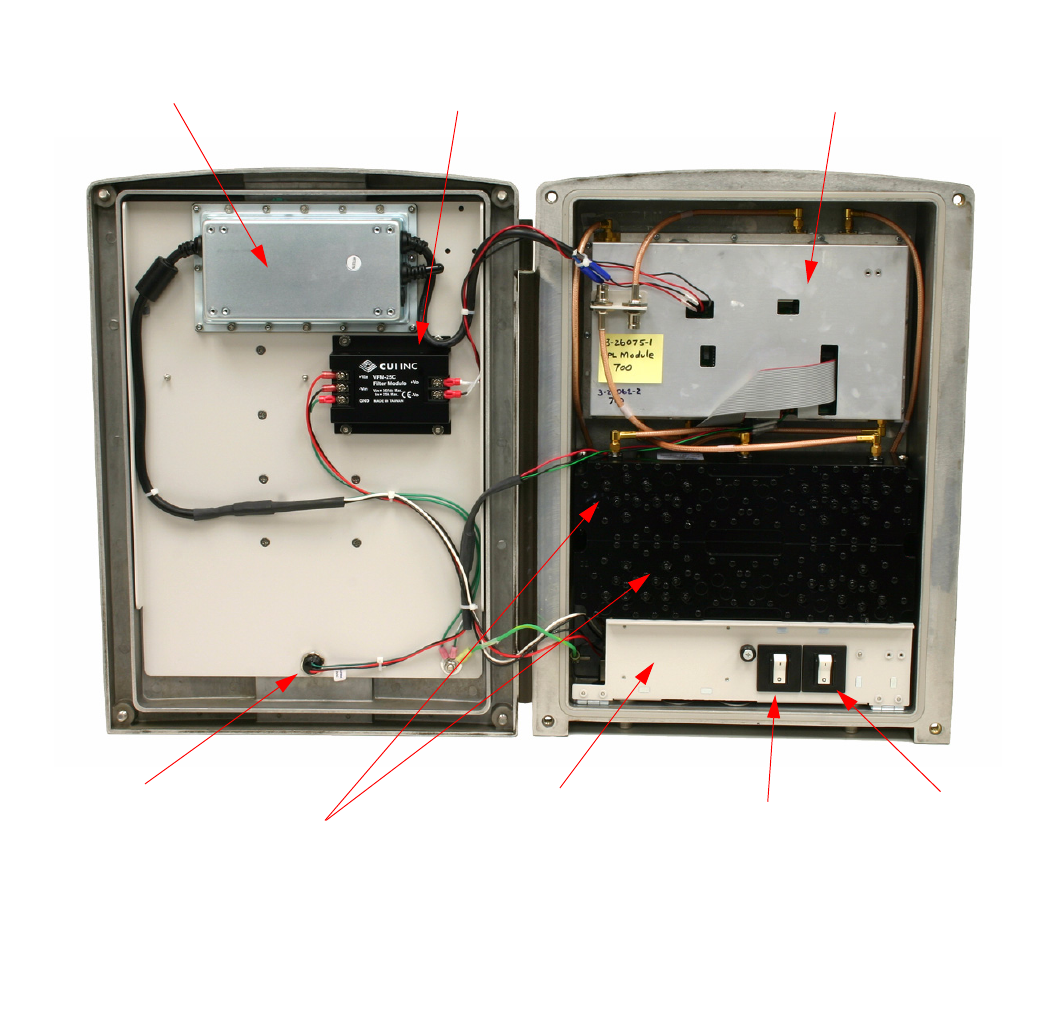
Front Door
Alarm Status LED Duplexers AC
On/Off
Switch
Backup DC Power
On/Off
Switch
Alarm Form-C
contact terminals
and Backup DC
Power terminals
on back of this
drop down plate
Figure 1: SBII+ booster system in a typical clam-shell cabinet enclosure.
(800 MHz unit shown as an example)

Bird Technologies Manual 7-9598-2.1(Rough Draft) 10/17/16 Page 8
included as part of the overall system installation.
Because of its modular design the completed
booster system can be housed in a variety of cabi-
net designs. The most common cabinet enclosure
used for the system is a clam shell type using con-
vectional cooling. This cabinet style is used in illus-
trations throughout this manual as an example.
The module is powered by a DC power supply
assembly. A front view of the booster with the door
open is shown in Figure 1. Specifications for the
signal booster are listed in Table 1.
Class B SB Module
The Class B SB module contains and shields both
the uplink and downlink signal amplification paths.
The maximum gain for each path is 80 dB and a
maximum output power of 2 Watts is typical. Out-
put power is limited by an Output Level Control
(OLC) so as not to exceed the 5 Watt ERP FCC
specification or not to exceed the user output
power limit setting. The customer can configure the
module via an Ethernet connection and a software
user interface (GUI). The GUI can be used to alter
the gain of either or both signal paths, monitor sys-
tem performance metrics, vary network and SNMP
notification settings.
UNPACKING
It is important to report any visible damage to the
carrier immediately. It is the customer's responsibil-
ity to file damage claims with the carrier within a
short period of time after delivery (1 to 5 days).
Care should be taken when removing the unit from
the packing box to avoid damage to external heat-
sink fins.
Parameter Specification
Frequency Range
UHF
700 MHz
800 MHz
Dual Band
450 - 470 and 470 - 512 MHz
764 - 805 MHZ (US) or 764 - 806 MHz (Canada)
806 - 861 MHz (US) or 806 - 869 MHz (Canada)
758 - 861 Mhz (US) or 764 - 869 MHz (Canada)
Gain Range 30 dB - 80 dB
Gain Adjustment 0.5 dB steps
Output Power
Max Set-point Range
Adjustment
OLC Active Range
Output Power Limit Accuracy
21 - 33 dBm
0.5 dB steps
0 - 30 dB
+/- 1 dB
3rd Order Output Intercept Point +55 dBm min, with no attenuation (out of PA)
AC Input Power 100 - 240 VAC; 50 - 60 Hz
DC Backup Voltage +20 to +27 VDC (+24 VDC nominal)
Operating Temperature Range -30°C to +50°C
Sample Port (inside unit) 30 dB
Alarm
Form-C Contacts
Tri-Color LED (located on front door)
SNMP V3.0
SMTP (email notification)
Input - Output Connectors N (F)
RF Sample Connector BNC (F) (internal only)
Table 1: Specifications.
Bird Technologies Manual 7-9598-2.1(Rough Draft) 10/17/16 Page 9
INSTALLATION
The following sections discuss general consider-
ations for installing the booster. All work should be
performed by qualified personal in accordance with
local codes.
Location
The layout of the signal distribution system will be
the prime factor in determining the mounting loca-
tion of the booster. However, safety and service-
ability are also key considerations. The unit should
be located where it cannot be tampered with by the
general public, yet is easily accessible to service
personnel. Also consider the weight of the unit and
the possibility for injury if the unit should become
detached from its mounting surfaces for any rea-
son.
Although signal boosters can operate for years
without being attended to, the unit will need to be
accessed by service personnel with troubleshoot-
ing equipment, such as digital multimeters and
spectrum analyzer or a laptop computer from time
to time. The location of the power source will also
have a bearing on the mounting location. SBII+
uses external heat sinks and needs to be mounted
where there can be an unobstructed air flow over
the heat sinks fins. The SBII+ cabinet will stay
warm during normal operation so in the interest of
equipment longevity, avoid locations that carry hot
exhaust air or are continually hot.
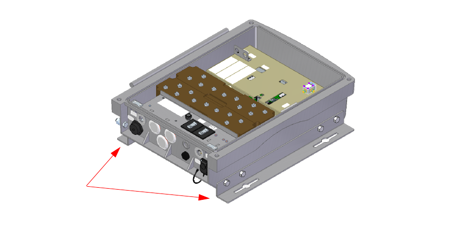
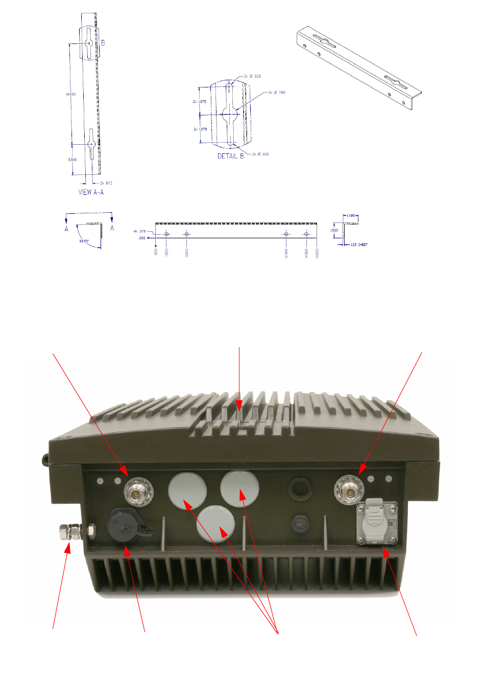
Mounting
Figure 2 shows the mounting scheme for the cabi-
net. Brackets are attached to the sides of the cabi-
net and the unit is then mounted to the wall using
3/8” (10 mm) diameter steel bolts (not supplied).
We recommend flat washers and a lock washer
under the head of the bolt. Nut and bolt mounting is
preferred to the use of lag bolts whenever possible.
Use backer blocks where necessary to spread the
force over a larger surface area. In areas of known
seismic activity, additional devices such as tether
lines may be necessary. The mounting hole dimen-
sions of the mounting brackets are shown in Fig-
ure 3.
Because Bird Technologies cannot anticipate all
the possible mounting locations and structure
types where these devices will be located, we rec-
ommend consulting local building inspectors, engi-
neering consultants or architects for advice on how
to properly mount objects of this type, size and
weight in your particular situation. It is the cus-
tomer’s responsibility to make sure these devices
are mounted safely and in compliance with local
building codes.
CONNECTIONS
All cabling connections to the booster should be
made and checked for correctness prior to power-
ing up the system. Connections are made through
conduit ports on the bottom of the cabinet as
shown in Figure 4.
Figure 2: Mounting plates attached to the cabinet.
Mounting
Brackets
Bird Technologies Manual 7-9598-2.1(Rough Draft) 10/17/16 Page 10
DL Out
UL IN
UL Out
DL In
Fiber Optic
Connector
Enet
Connector
Openings for
Conduits
Ground
Lug
Status
LED
Figure 4: Bottom view of booster.
Figure 3: Mounting bracket hole dimensions.
Bird Technologies Manual 7-9598-2.1(Rough Draft) 10/17/16 Page 11
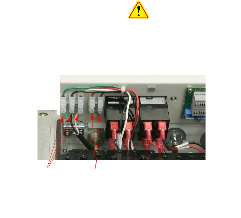
AC Line
Signal Booster II+ is designed to be hard-wired to
100 - 240 single phase AC lines at 50 - 60 Hz.
Bring the AC line into the cabinet through a conduit
opening on the bottom of the enclosure. Connect
the AC line to the terminal strip located behind the
flip-up panel and to the right of the On/Off switches.
Refer to the photo shown in Figure 5. The output
side of the switch is connected to the input of the
power supply assembly. Use conduit for running
the AC wiring into the SB II+ and #14 gauge or
larger conductors.
Backup DC Power
SB II+ may be run on a DC power source that can
supply 20 to 27 volts DC (24 VDC nominal). Screw
terminals are provided for this connection as
shown in figure 5). Bring the DC backup voltage
into the cabinet through a conduit opening on the
bottom of the enclosure. Connect the DC lines to
the terminal strip located behind the flip-up panel
and to the right of the On/Off switches. Use #16 or
#18 gauge wire for this connection.
The power system in SB II+ automatically switches
to this backup DC input when the AC supply fails
for any reason including a power outage or inten-
tional disconnection. It is not necessary that this
connection be made for normal operation on the
AC line.
RF Connections
All RF cabling connections to the booster should
be checked for correctness prior to powering up the
system. N(F) bulkhead connectors are provided on
the bottom of the cabinet for connection to the sig-
nal distribution system. Be sure that the correct
branch of the distribution system is connected to its
corresponding Uplink/Downlink connector or the
system will not work properly. Using high-quality
connectors with gold center pins is advised. Flexi-
ble jumper cables made of high-quality coax are
also acceptable for connecting to rigid cable sec-
tions.
CAUTION: The maximum RF input
power level for the SBII+ is -20 dBm.
Stronger input signals will cause the
unit to exceed it’s IM specifications.
Static Input signals stronger than -10
dBm may physically damage the unit.
AC Line
connections
here
Backup DC
connections
here
Figure 5: AC and DC power connections to the SBII+ cabinet.

Bird Technologies Manual 7-9598-2.1(Rough Draft) 10/17/16 Page 12
PRE-RF CONNECTION TESTS
Antenna isolation between the uplink and downlink
branches should be measured before connecting
the signal booster to the antenna system. This step
is necessary to insure that no conditions exist that
could possibly damage the signal booster and
should not be skipped for even the most thoroughly
designed system.
The booster is factory preset to 50 dB
gain and should only be reset to a
higher value after determining the
safe maximum gain based on antenna
isolation.
Test Equipment
The following equipment is required in order to per-
form the pre-installation measurements.
1) Signal generator for the frequencies of interest
capable of a 0 dBm output level. Modulation is
not necessary.
2) Spectrum analyzer that covers the frequencies
of interest and is capable of observing signal
levels down to -100 dBm or better.
3) Double shielded coaxial test cables made from
RG142, RG55 or RG223 coaxial cable.
Antenna Isolation
Just like the feedback squeal that can occur when
the microphone and speaker get too close to each
other in a public address system, a signal booster
can start to self oscillate. This can occur when the
isolation between the input antenna or signal
source and the output distribution system does not
exceed the signal boosters gain by at least 15 dB.
Oscillation will reduce the effectiveness of the sys-
tem and may possibly damage the power amplifier
stages.
In general, if one or both antenna ports are con-
nected to sections of radiating coaxial cable (lossy
cable) the isolation will be more than adequate
because of the high coupling loss values that are
encountered with this type of cable. When a net-
work of antennas are used for the input and output,
this problem is much more likely. Isolation values
are relatively easy to measure with a spectrum
analyzer and signal generator.
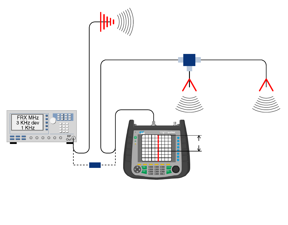
Procedure for Measuring Antenna Isolation
1) Set the signal generator for a 0 dBm output
level at the center frequency of one of the signal
boosters passbands.
2) Set the spectrum analyzer for the same center
frequency and a sweep width equal to or just
slightly greater than the passband chosen in
step one.
3) Connect the test leads of the signal generator
and the spectrum analyzer together using a
female barrel connector, see Figure 6. Observe
the signal on the analyzer and adjust the input
attenuator of the spectrum analyzer for a signal
level that just reaches the 0 dBm level at the top
of the graticule.
4) Referring to figure 6, connect the generator test
lead to one side of the signal distribution system
(external antenna) and the spectrum analyzer
lead to the other (internal distribution system)
and observe the signal level. The difference
between this observed level and 0 dBm is the
isolation between the sections. If the signal is
too weak to observe, the spectrum analyzer's
bandwidth may have to be narrowed and its
input attenuation reduced. Record the isolation
value for future reference. The isolation value
measured should exceed the signal boost-
ers gain figure by at least 15 dB.
5) Repeat step 4 again with the signal generator
set at the passband edges in order to see if the
isolation is remaining relatively constant over
the complete width of the passband.
6) Repeat the isolation measurements if neces-
sary at other system passbands to determine
the overall minimum isolation value for the sys-
tem. Physical modification of the antenna sys-
tem maybe required in order to reach an
acceptable minimum value.
RF EXPOSURE
To comply with FCC RF exposure compliance
requirements, a separation distance of at least
32.5 cm (for UHF), 23 cm (for 700 MHz PS), 27 cm
(for 800 MHz PS), or 22 cm (for 800 MHz CRMS)
must be maintained between the Donor antenna of
this equipment and all persons. To comply with
FCC RF exposure compliance requirements, a
separation distance of at least 32.5 cm (for UHF),
NOTE
Bird Technologies Manual 7-9598-2.1(Rough Draft) 10/17/16 Page 13
20 cm (for 700 MHz PS), 21 cm (for 800 MHz PS),
or 27 cm (for 800 MHz CRMS) must be maintained
between the DAS antenna of this equipment and
all persons. This equipment must not be co-located
or operating in conjunction with any other antenna
or transmitter.
To comply with IC RF exposure compliance
requirements, a separation distance of at least
39.4 cm (for UHF), 30.5 cm (for 700 MHz), 36.1 cm
(for 800 MHz) must be maintained between the
Donor and DAS antennas of this equipment and all
persons.
EXPOSITION RF
Pour conformer aux exigences d'exposition de
FCC RF, une distance de séparation d'au moins
32.5 cm (pour UHF), 23 cm (pour 700 MHz PS), 27
cm (pour 800 MHz PS), or 22 cm (pour 800 MHz
CRMS) doit être maintenue entre les Donor
antenne de cet équipement et toutes les per-
sonnes. Pour conformer aux exigences d'exposi-
tion de FCC RF, une distance de séparation d'au
moins 32.5 cm (UHF), 20 cm (pour 700 MHz PS),
21 cm (pour 800 MHz PS), or 27 cm (pour 800
MHz CRMS) doit être maintenue entre les DAS
antenne de cet équipement et toutes les per-
sonnes. Cet équipement ne doit pas être co-local-
isé ou exploités en conjonction avec toute autre
antenne ou transmetteur.
Pour conformer aux exigences d'exposition de IC
RF, une distance de séparation d'au moins 39.4 cm
(pour UHF), 30.5 cm (pour 700 MHz), 36.1 cm
(pour 800 MHz) doit être maintenue entre les
Donor et DAS antennes de cet équipement et
toutes les personnes.
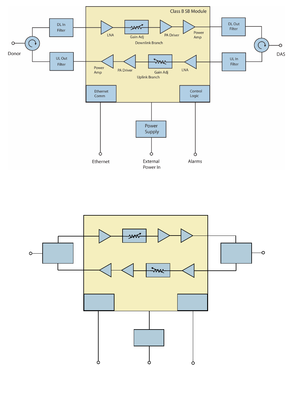
SIGNAL FLOW BLOCK DIAGRAM
Figure 7A and 7B is the signal flow block diagram
for the typical 700/800 or UHF SBII+ booster. The
block shown in the center of the drawing is the
Signal Generator
External
Antenna
(YAGI)
Spectrum Analyzer
Isolation (dB)
Zero Loss
Reference
Internal
Signal Distribution
System
(Omni-directional
Antennas)
Figure 6: Typical test equipment interconnection for measuring antenna isolation.
Bird Technologies Manual 7-9598-2.1(Rough Draft) 10/17/16 Page 14
Figure 7A: Signal flow block diagram of the typical UHF SBII+ Booster.
Figure 7B: Signal flow block diagram of the typical 700/800 SBII+ Booster.
Ethernet
Comm
Control
Logic
LNA Gain Adj PA Driver Power
Amp
LNA
Gain Adj
PA Driver
Power
Amp
Uplink Branch
Downlink Branch
Class B SB Module
Power
Supply
DAS
Donor
External
Power In
Ethernet Alarms
Duplexer
Duplexer
DLOut
ULIn
DLIn
ULOut
Bird Technologies Manual 7-9598-2.1(Rough Draft) 10/17/16 Page 15
Class B SB Module. The external passive filters
provide the isolation between the uplink and down-
link paths and are required to prevent oscillation.
The size of the external passive filters will deter-
mine the size of the enclosure or the amount of
rack space needed. The connections between the
module and the external passive filters would be
made with double shielded coaxial cable. The fil-
ters also insure that only signals in the desired
operational band are amplified and not those of
other radio services. Isolators may be used as
shown in the UHF block diagram to simplify the RF
connections to the two signal paths or appropri-
ately phased cables might also be used.
OPERATION
Power is applied to the booster by turning on the
AC and DC power switches located on the flip-up
panel as shown in figure 1. The status LED located
on the front door of the unit will illuminate indicating
that operational power is being applied.
Caution: RF ports must be termi-
nated before energizing booster.
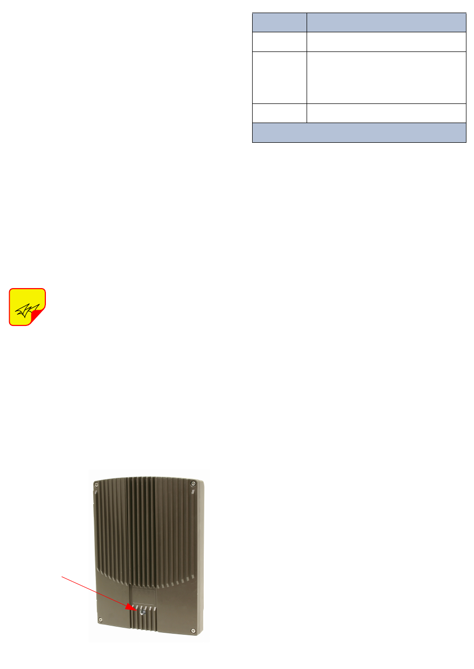
Status LED
The status LED is located on the front cover of the
unit as shown in Figure 8. This is a tri-color indica-
tor (red, yellow, green). Each color represents a dif-
ferent status as listed in Table 2.
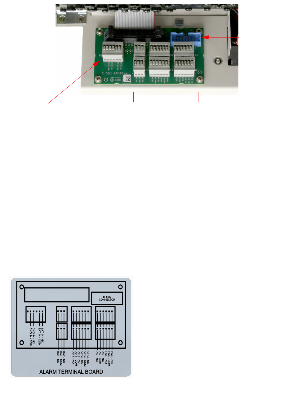
Alarm Form-C Contacts
ALARM Form-C relay contacts are located on the
back of the flip-up panel as shown in Figure 9.
These push-on style terminals are intended for
connection to the customer’s supervisory and data
acquisition system. Both normally open and nor-
mally closed contacts are available for each of five
alarm functions.
The normal condition for the SBII+ is power
applied, no alarms occurring, and the booster
operating as usual with the front door status LED
colored green. Under these normal conditions
there will be continuity between the Com and NC
alarm contacts and no continuity between the COM
and NO alarm contacts. When an alarm condition
occurs the status LED on the front door will turn
red and the appropriate form-C contacts will
change state. When alarming there will be continu-
ity between the COM and NO alarm contacts and
no continuity between the COM and NC alarm con-
tacts. The alarm terminals are push-on type for
ease of connection. Route the alarm wires through
one of the access holes in the bottom of the cabi-
net, strip about 3/16” of insulation from the end of
each wire and insert into the appropriate terminal.
To remove a wire push down on the tab and pull
out the wire. Use #20 or #22 gauge insulated wire
for alarm connections.
NFPA Compliant
The SBII+ signal booster is designed to be compli-
ant with the national public safety in-building codes
issued in the International Fire Code and the
National Fire Protection Association. The booster
accomplishes compliance when used in conjunc-
tion with an appropriate battery backup unit. An
optional battery backup unit is available from Bird
Technologies, model number 6160-H/E-24-NG.
Detailed installation and operating instructions for
the battery backup unit are included with the
backup unit when it ships from the factory.
NOTE
Figure 8: Status LED.
Status
LED
Color Status
Red System has a critical error.
Ye l l o w
System has an error - Warning: Per-
formance may be impaired. Example
- Loss of AC and system is running
on DC backup power.
Green System is running normally.
Table 2: Status LED.
Bird Technologies Manual 7-9598-2.1(Rough Draft) 10/17/16 Page 16
The NFPA system consists of the SBII+ signal
booster unit as well as the optional battery backup
unit. An NFPA compliant signal booster system is
designed to easily interface to fire alarm panels.
Five alarms are provided including SB Failure,
Loss of AC Power, Low Battery Capacity, Charge
Fail, and Antenna Malfunction. These five alarm
functions are available at the terminal contacts
shown in figure 9. Figure 10 is a close up view of
the terminal identification sticker attached to the
inside of the front door for customer convenience.
The terminals provide a common access point to
the alarm signal relay contacts. Available alarm
functions include;
SB Failure - this is a summed alarm that is active
when any number of fault conditions arise within
the booster unit such as when an over current or
high temperature event occurs.
Loss of AC Power - indicates that AC power to the
booster unit has failed.
Low Battery Capacity - the source of this alarm is
the battery backup unit and it indicates that the bat-
tery backup voltage level has dropped significantly.
Charge Fail - the source of this alarm is the battery
backup unit and it indicates failure of the battery
charger. If the battery charger looses AC power
this alarm will be active. It will also indicate when
the batteries will not properly charge.
Antenna Malfunction - indicates there is a loss of
cable connection integrity between the signal
booster unit and the remote antenna line sensor. In
order to detect an antenna malfunction an antenna
line sensor must be installed as close to the Donor
antenna as possible. This sensor allows the
Antenna Line Monitoring Unit inside the booster
cabinet to verify the continuity of the antenna line.
Refer to Figure 11. The sensor is waterproofed but
the connections to both the antenna and the
antenna feedline should be sealed to prevent water
entry. We recommend that the connections be
tightly and completely wrapped with rubber splicing
Figure 9: Alarm Form-C contacts.
Alternate alarm
terminal plug
Input terminal for alarms
sourced in the Battery
backup unit.
Alarm Form-C terminals
Figure 10: Alarm terminal identification sticker.
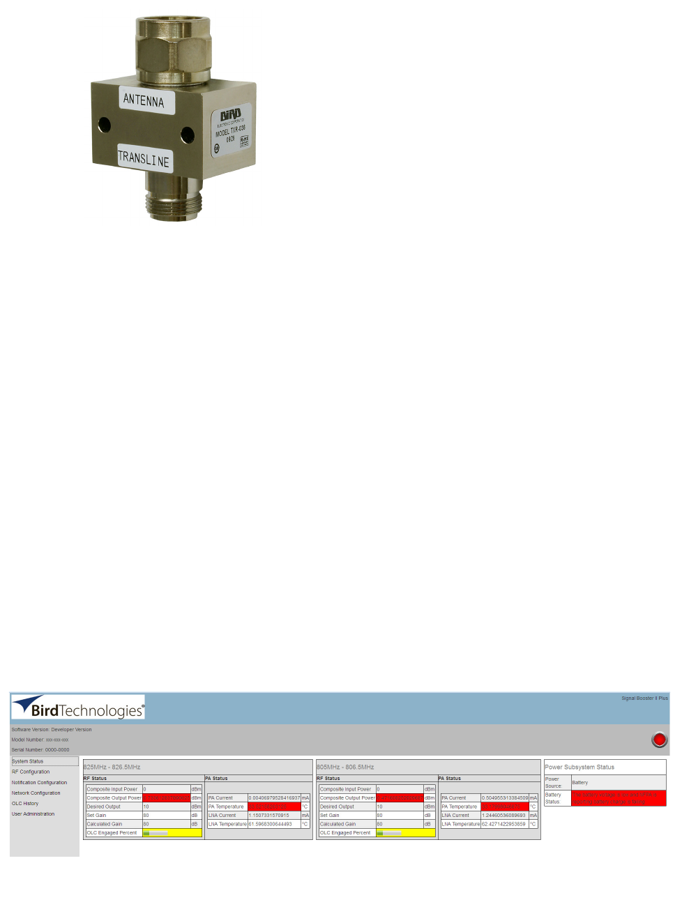
Bird Technologies Manual 7-9598-2.1(Rough Draft) 10/17/16 Page 17
tape.Connect the port that is labeled “antenna” on
the sensor to your donor antenna and the port that
is labeled “transline” to the antenna feedline cable
coming from the signal booster.
All five of the alarms use “supervising” alarm cir-
cuits. A supervised circuit includes technology that
will detect open or shorted circuits regardless of
the alarm status. This is accomplished by using
EOL (end-of-line) resistors at the alarm terminal
strip in the signal booster cabinet. The value of the
EOL resistors is a function of the alarm panel so
you should consult the manual for the alarm panel
when you are determining the resistor value.
COMMUNICATING WITH THE BOOSTER
The booster provides Ethernet connectivity that
allows user interaction via a web based user inter-
face (GUI). Communications will require connect-
ing your laptop computer to the Enet connector
located on the bottom of the unit as shown in figure
4. A standard Ethernet crossover cable is used to
make the connection between your laptop com-
puter and the booster cabinet.
System Status Submenu
Once your laptop computer is properly connected
to the signal booster a system summary submenu
screen will be displayed as shown Figure 12. The
top banner of this submenu screen shows the cur-
rent software version, model number, and serial
number of the booster. The front door status LED is
shown as an icon to the right of the banner and will
be updated in real time.
On the left-hand side of the page are a list of the
major submenus available to the user including
System Status, RF Configuration, Notification Con-
figuration, Network Configuration, OLC History,
and User Administration. Place your cursor over a
particular submenu heading and left click to make
a selection. Each major submenu page contains a
group of related functions.
The center of the System Status submenu screen
is divided into three graphical boxes. Identical
boxes for the Uplink and downlink branches and a
smaller box for power subsystem status. The uplink
and downlink boxes have their passband displayed
on the top border of the box. Both RF Status values
and Power Amplifier status values are displayed in
a column format. The values displayed are updated
in real time. The OLC Engaged Percent is shown at
the bottom of the RF Status column as a bar graph
display. The light bar represents an average of
OLC gain reduction and ideally there should be lit-
tle or no light bar activity. OLC (output level control)
is meant to reduce gain for transient episodes of
very strong signals. However, when OLC is active,
gain is reduced for all signals being passed by that
Figure 11: The remote antenna line sensor.
(part # TXR-036).
Figure 12: System Summary submenu screen.
Bird Technologies Manual 7-9598-2.1(Rough Draft) 10/17/16 Page 18
booster branch and that reduction may compro-
mise communications for weaker signals in the
passband.
If a large portion of the bar graph is lit more than
occasionally, it is advised that the gain of that
branch be reduced or re-orient the antenna for bet-
ter isolation.
The power Subsystem Status reports on the cur-
rent power source operating the booster, either AC
or Battery Backup. In addition, battery status infor-
mation is displayed. This information is supplied by
the battery backup unit.
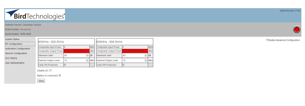
RF Configuration Submenu
The RF Configuration submenu screen is shown in
Figure 13. Like the system status screen it is bro-
ken into two identical graphical boxes, one for the
uplink branch and one for the downlink branch. The
user is allowed to adjust the maximum gain and the
desired output level. The maximum gain is adjust-
able from 0 to 80 dB and the desired gain is adjust-
able from -50 to 30 dBm.
In addition to the branch adjustments this submenu
screen will also allow the user to enable or disable
AC power operation. This is accomplished by click-
ing on the box next to the label “Disable/Enable
AC”. Note that any changes made on this submenu
screen will not become active until the user clicks
on the SAVE button. If a battery backup system is
connected to the booster the user should place a
check mark in the appropriate battery is connected
box. Please note that if there is not a battery
backup connected to the booster and the AC oper-
ation is disabled, then on air signals will not pass
through the booster in either branch.
On the right side of the submenu screen under the
Status LED icon there is a check box for turning on
advanced configuration items. Currently this
includes OLC adjustments for Hold Time and
Decay Time. OLC Hold Time is adjustable from 0.1
to 5 seconds and determines the amount of time
that OLC will be applied (once activated by a
strong input signal) before OLC decay begins. OLC
decay begins after the user specified hold time is
expired. Decay Time can be adjusted between 0.1
to 1 seconds. Decay time will determine how long it
takes for the applied OLC to fade from on to off.
Notification Configuration Submenu
This submenu allows the user to define how alarm
and status notifications are passed onto the cus-
tomer using an SNMP format. Simple Network
Management Protocol (SNMP) is an Internet-stan-
dard protocol for managing devices on IP net-
works. The SNMP feature is designed to provide
reliable internet notification of an alarm occurrence
or a change in operational status in the booster. In
order to configure the booster to send SNMP mes-
sages (called traps) to a destination device, such
as your computer, the following values need to be
entered into the booster; System location, the IP
address of the destination computer, Authentica-
tion type, User name, Password, and Encryption
type, and the Encryption passphrase. To enter
these values into the booster click on the ADD
SERVER button shown on the Notification sub-
menu screen. Each time the button is selected an
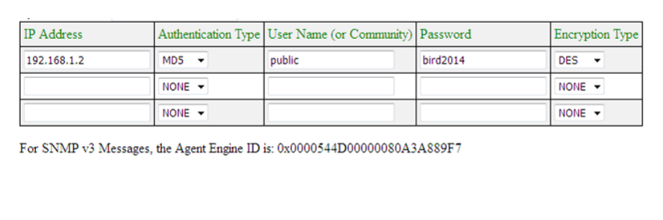
entry row will be created. An example of the SNMP
configuration table is shown in Figure 14.
The System location is a user defined string which
will be returned with every trap that is generated
and can assist the user in identifying which unit is
sending the trap message. Destination IP
Figure 13: RF Configuration submenu screen.
Bird Technologies Manual 7-9598-2.1(Rough Draft) 10/17/16 Page 19
addresses that are entered into the table should be
the IP addresses of the computers that you want
the traps to be sent to. These destination comput-
ers must have SNMP manager software installed
and running in order to receive the messages.
SNMP manager software installation into the desti-
nation computers is the customers responsibility.
Consult with your IT specialist for assistance.
Authentication type is used to verify that the person
receiving the trap is the person the trap is intended
for. Authentication type choices are NONE, MD5,
or SHA, with SHA being the strongest encryption
type. When using authentication and/or encryption
the User Name is the name of the person to
receive the trap. If not, this is the community name
of the trap receiver. The Password is a string used
to encrypt and authenticate the user. It is only used
when authentication and/or encryption types are
enabled. The Encryption type is used to protect the
contents of the message from unauthorized receiv-
ers. Encryption type choices are NONE, DES, or
AES, with AES being the strongest supported
encryption type.
The Agent ID is a value that uniquely identifies the
agent sending the traps. The agent is software
which runs on the device being monitored and in
this case is the signal booster. The SNMP man-
ager software receives the traps and can be run on
your computer or another server on your network.
For traps that use encryption and/or authentication
the manager needs to be configured to receive
traps from the specified agent ID. This number is
shown underneath the table, refer to figure 14.
Whenever values in the SNMP Configuration table
are changed you must click on the SAVE button to
initiate the changes.
INITIAL SNMP SETUP
When the booster is installed the SNMP feature
should be setup for proper communications. There
are several steps required for proper setup of the
SNMP feature as discussed below.
1) Connect a laptop directly to the booster. The
booster is shipped from the factory setup for
static IP addressing and with a default IP
address of “192.168.1.1”. The factory default
subnet mask is “255.255.255.0”. Change the
factory default IP address of the booster to one
provided by your IT department.
2) Use the Network Configuration submenu to
setup the DHCP as either active or inactive.
When DHCP is inactive the booster will be
using a static IP and the user must enter values
for IP address, netmask, and gateway. Make
sure you consult with your IT department
regarding setting DCHP active or inactive.
3) Use the SNMP Configuration table to enter the
destination device addresses. These are
addresses where the SNMP feature will send
trap messages whenever a qualifying event
takes place.
4) Setup the SNMP format using the SNMP Con-
figuration table. Items that need to be config-
ured include Authentication Type, User Name,
Password, and Encryption Type. Consult with
your IT specialist for assistance.
5) Load the SNMP manager software into the des-
tination computer and configure the manager so
that it will be able to receive the SNMP traps.
6) Download MIB files from the Bird Technologies
website (www.birdrf.com) and load the MIB files
Figure 14: SNMP configuration table.
Bird Technologies Manual 7-9598-2.1(Rough Draft) 10/17/16 Page 20
into your SNMP manager software. The MIB
files allow the SNMP manager software to sort
out the trap messages into an understandable
message format.
The signal booster supports several SNMP Config-
uration validation checks which help ensure the
configuration is setup in a logical format. The vali-
dation checks include;
A) If encryption is enabled but authentication is not
enabled a popup window will appear stating that
you must enable authentication when encryp-
tion is enabled.
B) If Authentication and/or Encryption is enabled
and a password is entered which is < 8 charac-
ters long an error message will be displayed.
C) If an IP address is entered but a User Name is
not entered a popup warning will appear but the
changes will be submitted.
D) If a User name is entered but an IP address is
not entered a popup warning will appear but the
changes will be submitted.
SNMP MANAGER EXAMPLE
SNMP manager software is designed to provide a
GUI style interface for the user so that traps sent
from the booster can be received and displayed for
viewing. The SNMP manager software chosen and
used by the customer is up to the customers dis-
cretion and as such may not exactly match the
example shown in this discussion. SNMP manager
software packages will need to be properly config-
ured in order to successfully receive messages
from the booster. Refer to the SNMP configuration
setup discussed earlier in this manual and ask your
IT specialists for assistance.
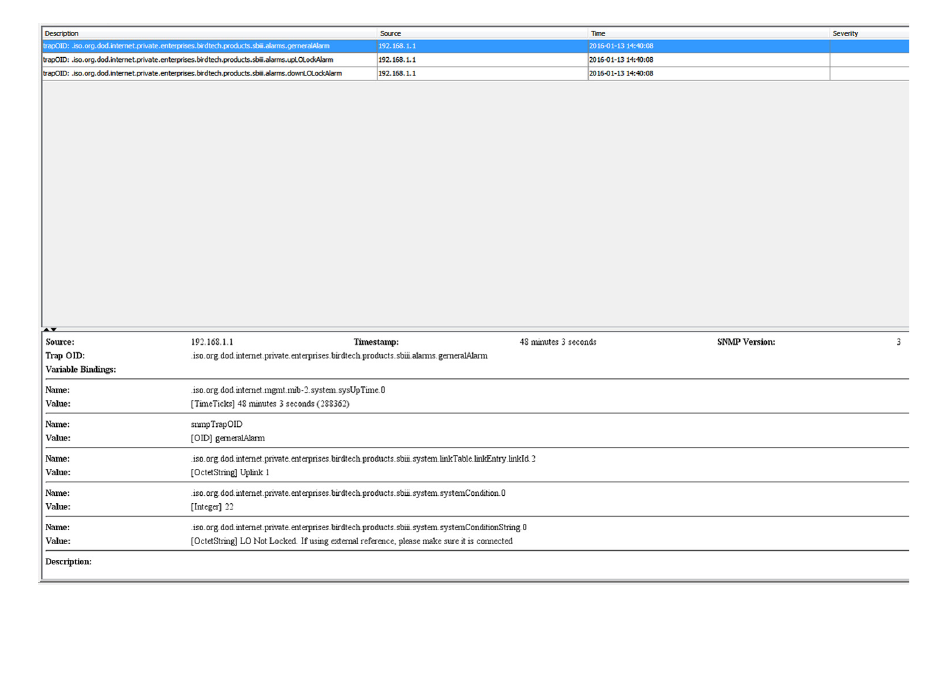
When a qualifying event occurs in the booster a
trap is formulated and sent to the destination com-
puter. A typical trap is shown in Figure 15. In the
example shown the trap messages are shown at
the top of the screen display. Three trap messages
have been received by this manager from a signal
booster. In this particular SNMP manager software
Figure 15: SNMP Manager example.
Bird Technologies Manual 7-9598-2.1(Rough Draft) 10/17/16 Page 21
package if a trap message is selected the details of
that message are displayed in the lower portion of
the screen. The details show the raw message as it
was received by the manager while the upper box
shows the message after it has been interpreted by
the MIB files.
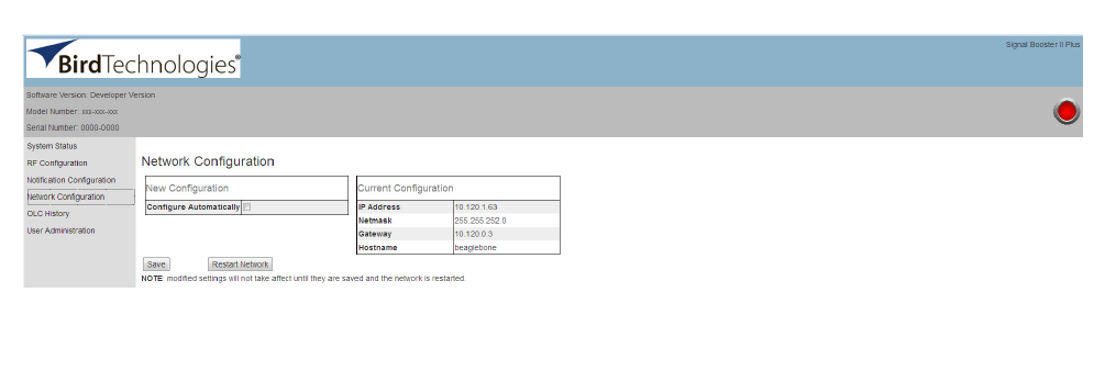
Network Configuration Submenu
Values for IP Address, Netmask, the Gateway and
MAC Address are displayed on the network config-
uration submenu screen. Refer to Figure 16.
The network configuration page allows the user to
enable or disable DCHP. This is accomplished by
placing a check mark in the box next to the label
“Configure Automatically”. The Dynamic Host Con-
trol Protocol (DHCP) is a standardized networking
protocol used on IP networks for dynamically dis-
tributing network configuration parameters, such as
IP addresses for interfaces and services. With
DHCP, computers request IP addresses and net-
working parameters automatically from a DHCP
server, reducing the need for a network administra-
tor or a user to configure these settings manually.
The DCHP (Dynamic Host Configuration Protocol)
is either active or inactive. When DCHP is active
the values for IP address, netmask, and gateway
are set to zero. When the DCHP is inactive (default
setting from the factory) the IP address, netmask,
and gateway values can be modified by the user by
typing the desired values into the associated box
and pressing the save button. The customer should
consult with their IT department to determine
whether DCHP should be active or inactive.
OLC History Submenu
This screen displays an OLC Datalog which is the
OLC data over the past 30 days for both uplink and
downlink branches of the system. This is a rolling
30 day log with day 31 overlapping day 1 and so
forth. Day zero represents the current day while
day one represents yesterday and so on. The
logged data is stored in non-volatile memory and
will not be erased when the unit is powered down.
The average OLC attenuation used when the OLC
was active is given both for individual days and
over the entire past 30 days. The percentage of
time the OLC was active is also given for both indi-
vidual days and over the past 30 days. This
archived information will permit the creation of a
user signal profile to facilitate optimum system con-
figuration and performance.
This archive feature will allow you to see if there
are transient episodes of strong signals perhaps
desensing other channels being amplified by the
booster.
User Administration Submenu
The User Administration submenu allows pass-
word protected access to the booster. The boxes
on this page are interactive. To make changes click
inside the box and a cursor will appear. The user is
queried for a User Name and User Password. The
default user name is “admin” and the default
password is “admin”. It is recommended that once
the booster system is installed approved users with
unique passwords are loaded into the system and
the default admin user/password is deleted.
Once the correct user name and password are
entered then a menu box for creating a new user
will be presented. To create a new user enter the
Figure 16: Network Configuration submenu screen.
Bird Technologies Manual 7-9598-2.1(Rough Draft) 10/17/16 Page 22
new user name and associated password. Confirm
the new password by entering it again and then
press the Create User button. Make sure you write
down the new user name and password for safe
keeping. A menu box for deleting a user is also pre-
sented. To delete a user enter their user name in
the box and click on the Delete User button.
MAINTENANCE AND REPAIR
Signal boosters manufactured by Bird Technolo-
gies can perform for years with little maintenance
and repair. However, if the amplifiers are subjected
to excessively high signal levels, power surges or
lightning strikes, failures may occur. The following
procedures may be followed for detecting a mal-
functioning unit or as part of a periodic mainte-
nance program.
1) The heatsink area should be cleared of dust
and debris.
2) Inspect the unit to see that the front door Status
LED is lit (remove any dust or debris that may
obscure the LED). This will verify that operating
power is flowing properly. Check all hardware
for tightness.
3) Compare system performance to initial perfor-
mance levels measured when the system was
first installed. Or measure the gain at any con-
venient frequency in the working frequency
band to verify that the performance is still within
specifications.

Bird Technologies Manual 7-9598-2.1(Rough Draft) 10/17/16 Page 23
Return Loss vs. VSWR
Return Loss VSWR
30 1.06
25 1.11
20 1.20
19 1.25
18 1.28
17 1.33
16 1.37
15 1.43
14 1.50
13 1.57
12 1.67
11 1.78
10 1.92
92.10
Watts to dBm
Watts dBm
300 54.8
250 54.0
200 53.0
150 51.8
100 50.0
75 48.8
50 47.0
25 44.0
20 43.0
15 41.8
10 40.0
537.0
436.0
334.8
233.0
130.0
dBm = 10log P/1mW
Where P = power (Watt)
Insertion Loss
Input Power (Watts)
50 75 100 125 150 200 250 300
325 38 50 63 75 100 125 150
2.5 28 42 56 70 84 112 141 169
232 47 63 79 95 126 158 189
1.5 35 53 71 88 106 142 177 212
140 60 79 99 119 159 199 238
.5 45 67 89 111 134 178 223 267
Output Power (Watts)
Insertion Loss
Free Space Loss
Distance (miles)
.25 .50 .75 12510 15
150 68 74 78 80 86 94 100 104
220 71 77 81 83 89 97 103 107
460 78 84 87 90 96 104 110 113
860 83 89 93 95 101 109 115 119
940 84 90 94 96 102 110 116 120
1920 90 96 100 102 108 116 122 126
Free Space Loss (dB)
Free space loss = 36.6 + 20log D + 20log F
Where D = distance in miles and F = frequency in MHz
Frequency (MHz)

Bird Technologies Manual 7-9598-2.1(Rough Draft) 10/17/16 Page 24
8625 Industrial Parkway, Angola, NY 14006 Tel: 716-549-4700 Fax: 716-549-4772 sales@birdrf.com www.bird-technologies.com