Bird Technologies Group 5PI618850 BI-DIRECTIONAL SIGNAL BOOSTER User Manual 61 88 50 V4 less block
Bird Technologies Group BI-DIRECTIONAL SIGNAL BOOSTER 61 88 50 V4 less block
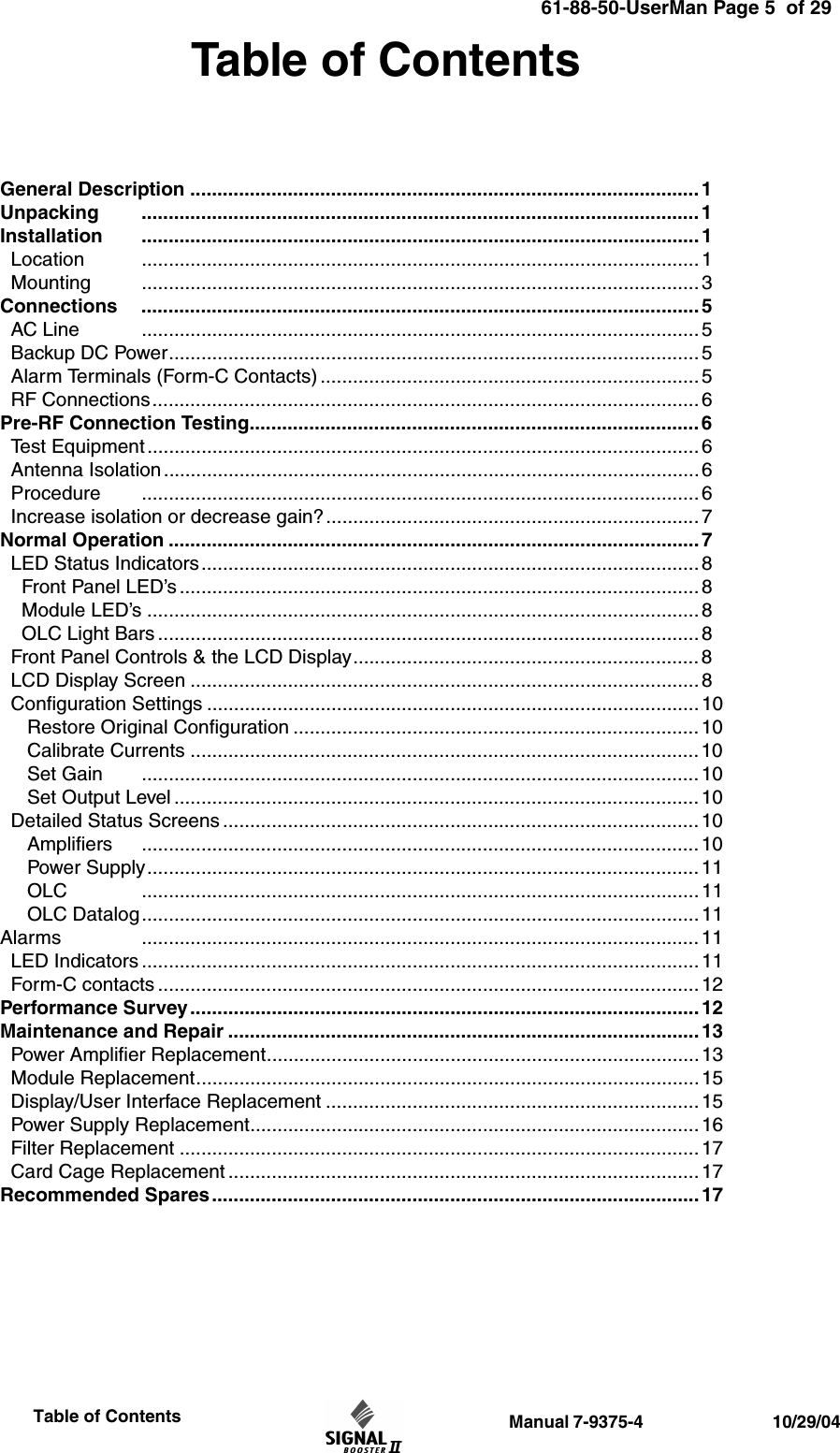
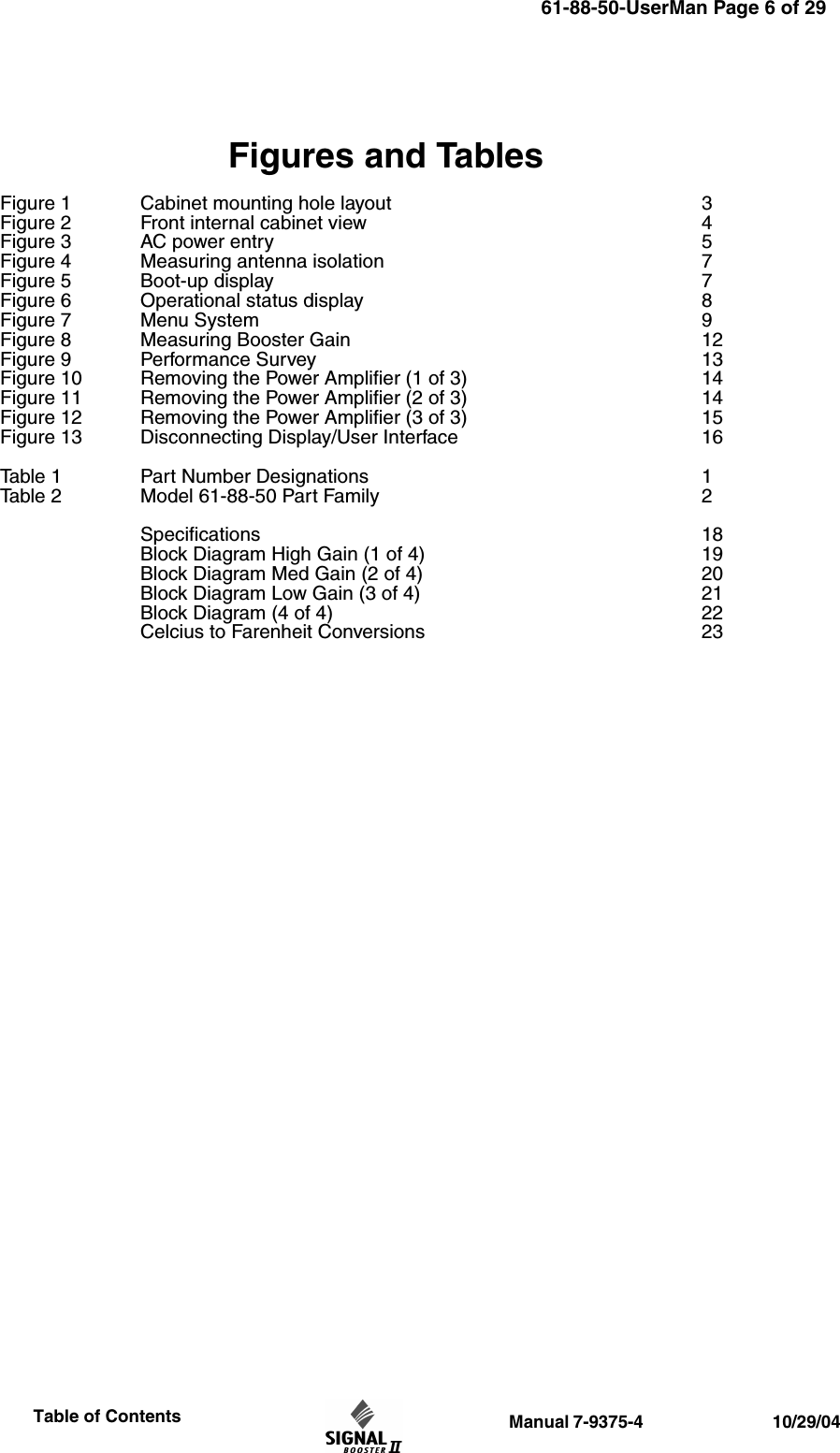
Contents
- 1. users manual 1 of 2
- 2. users manual 2 of 2
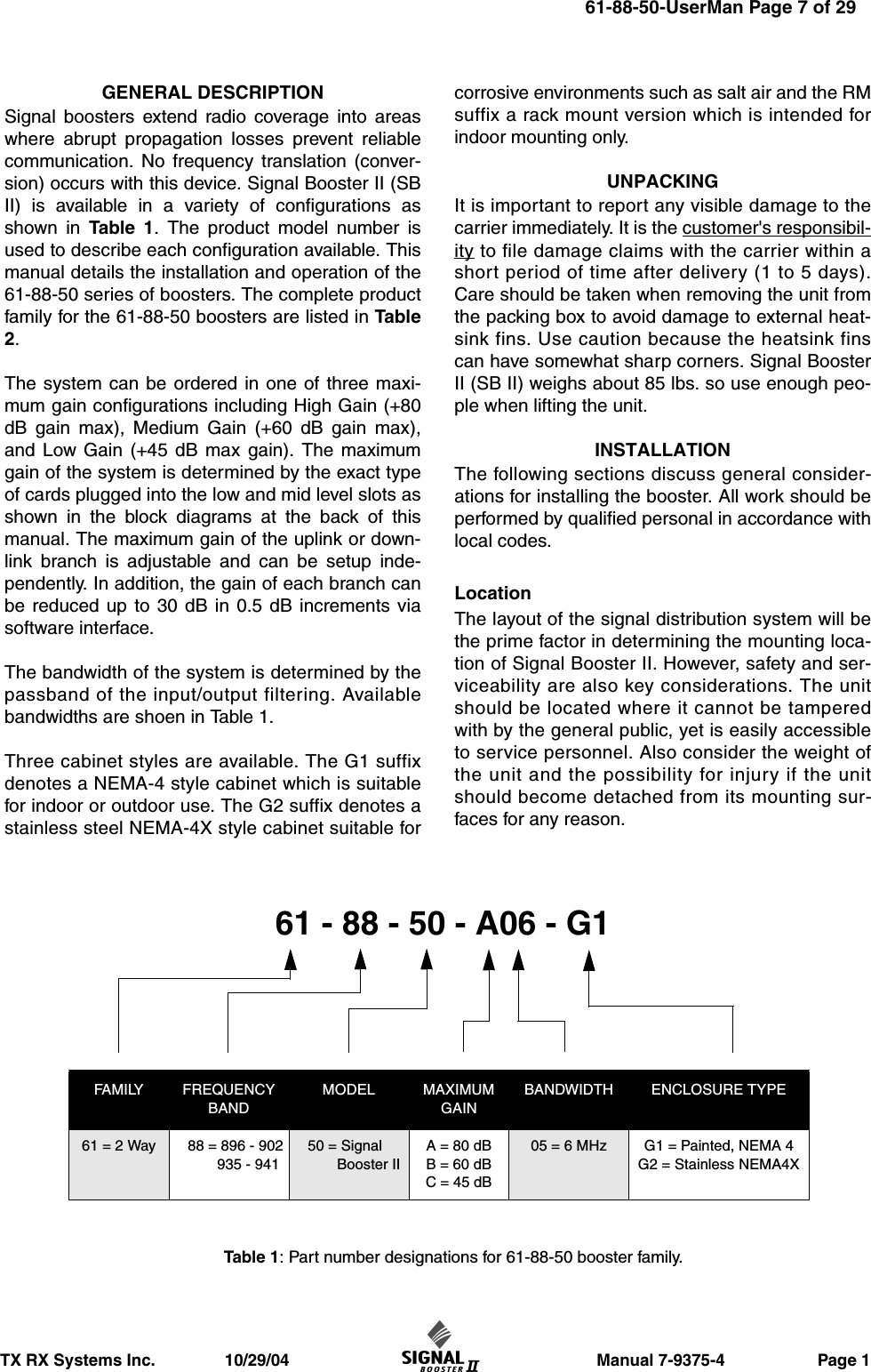
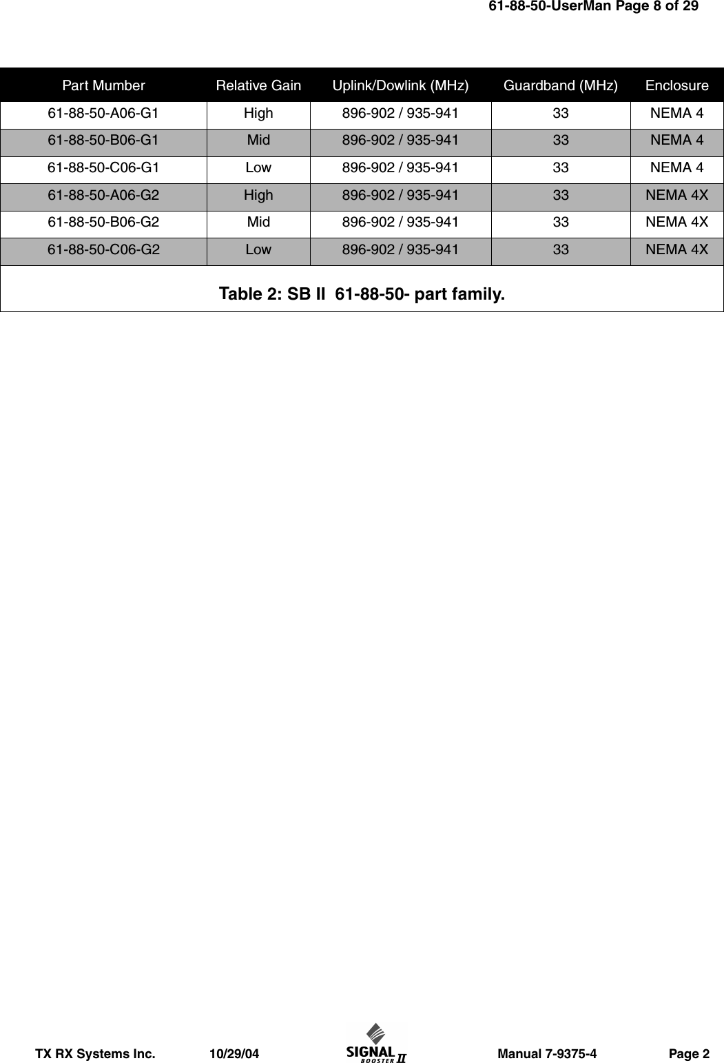
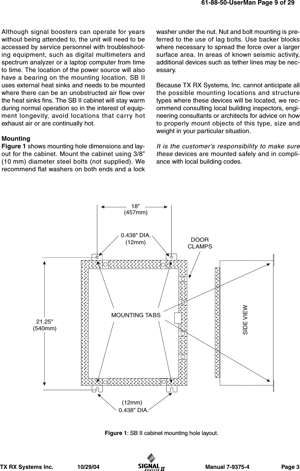
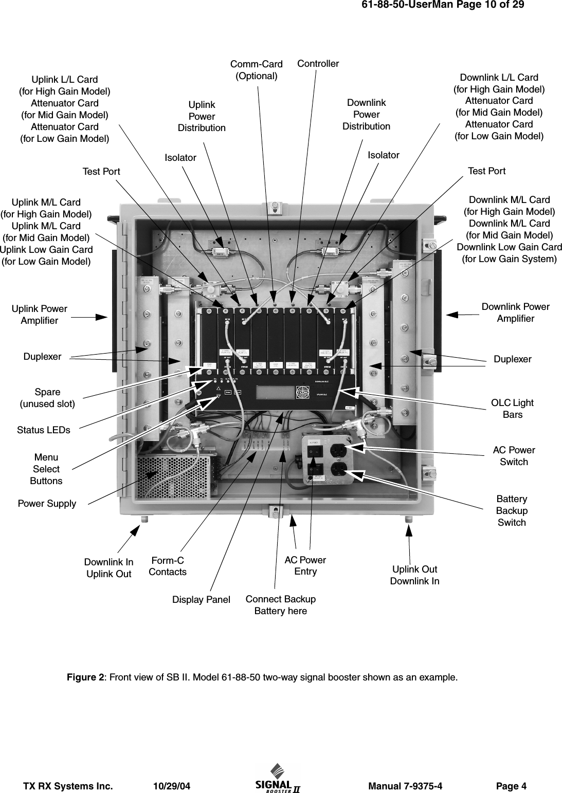
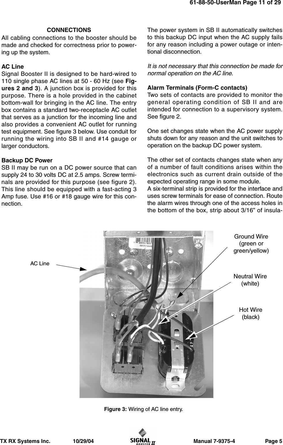
users manual 1 of 2