Bird Technologies Group 61170A Channelized Signal Booster User Manual
Bird Technologies Group Channelized Signal Booster
User Manual

YOU'RE HEARD, LOUD AND CLEAR.
8625 Industrial Parkway, Angola, NY 14006 Tel: 716-549-4700 Fax: 716-549-4772 sales@birdrf.com www.bird-technologies.com
Installation and Operation Manual for
the SBIII Channelized Signal Booster
Model 611-70A
Manual Part Number
7-9469

Warranty
This warranty applies for one year from shipping date.
TX RX Systems Inc. warrants its products to be free from defect in material and workmanship at the time of shipment.
Our obligation under warranty is limited to replacement or repair, at our option, of any such products that shall have
been defective at the time of manufacture. TX RX Systems Inc. reserves the right to replace with merchandise of
equal performance although not identical in every way to that originally sold. TX RX Systems Inc. is not liable for dam-
age caused by lightning or other natural disasters. No product will be accepted for repair or replacement without our
prior written approval. The purchaser must prepay all shipping charges on returned products. TX RX Systems Inc.
shall in no event be liable for consequential damages, installation costs or expense of any nature resulting from the
purchase or use of products, whether or not they are used in accordance with instructions. This warranty is in lieu of all
other warranties, either expressed or implied, including any implied warranty or merchantability of fitness. No repre-
sentative is authorized to assume for TX RX Systems Inc. any other liability or warranty than set forth above in con-
nection with our products or services.
TERMS AND CONDITIONS OF SALE
PRICES AND TERMS:
Prices are FOB seller’s plant in Angola, NY domestic packaging only, and are subject to change without notice. Fed-
eral, State and local sales or excise taxes are not included in prices. When Net 30 terms are applicable, payment is
due within 30 days of invoice date. All orders are subject to a $100.00 net minimum.
QUOTATIONS:
Only written quotations are valid.
ACCEPTANCE OF ORDERS:
Acceptance of orders is valid only when so acknowledged in writing by the seller.
SHIPPING:
Unless otherwise agreed at the time the order is placed, seller reserves the right to make partial shipments for which
payment shall be made in accordance with seller’s stated terms. Shipments are made with transportation charges col-
lect unless otherwise specified by the buyer. Seller’s best judgement will be used in routing, except that buyer’s routing
is used where practicable. The seller is not responsible for selection of most economical or timeliest routing.
CLAIMS:
All claims for damage or loss in transit must be made promptly by the buyer against the carrier. All claims for shortages
must be made within 30 days after date of shipment of material from the seller’s plant.
SPECIFICATION CHANGES OR MODIFICATIONS:
All designs and specifications of seller’s products are subject to change without notice provided the changes or modifi-
cations do not affect performance.
RETURN MATERIAL:
Product or material may be returned for credit only after written authorization from the seller, as to which seller shall
have sole discretion. In the event of such authorization, credit given shall not exceed 80 percent of the original pur-
chase. In no case will Seller authorize return of material more than 90 days after shipment from Seller’s plant. Credit
for returned material is issued by the Seller only to the original purchaser.
ORDER CANCELLATION OR ALTERATION:
Cancellation or alteration of acknowledged orders by the buyer will be accepted only on terms that protect the seller
against loss.
NON WARRANTY REPAIRS AND RETURN WORK:
Consult seller’s plant for pricing. Buyer must prepay all transportation charges to seller’s plant. Standard shipping pol-
icy set forth above shall apply with respect to return shipment from TX RX Systems Inc. to buyer.
DISCLAIMER
Product part numbering in photographs and drawings is accurate at time of printing. Part number labels on TX RX
products supersede part numbers given within this manual. Information is subject to change without notice.
Bird Technologies Group TX RX Systems Inc.
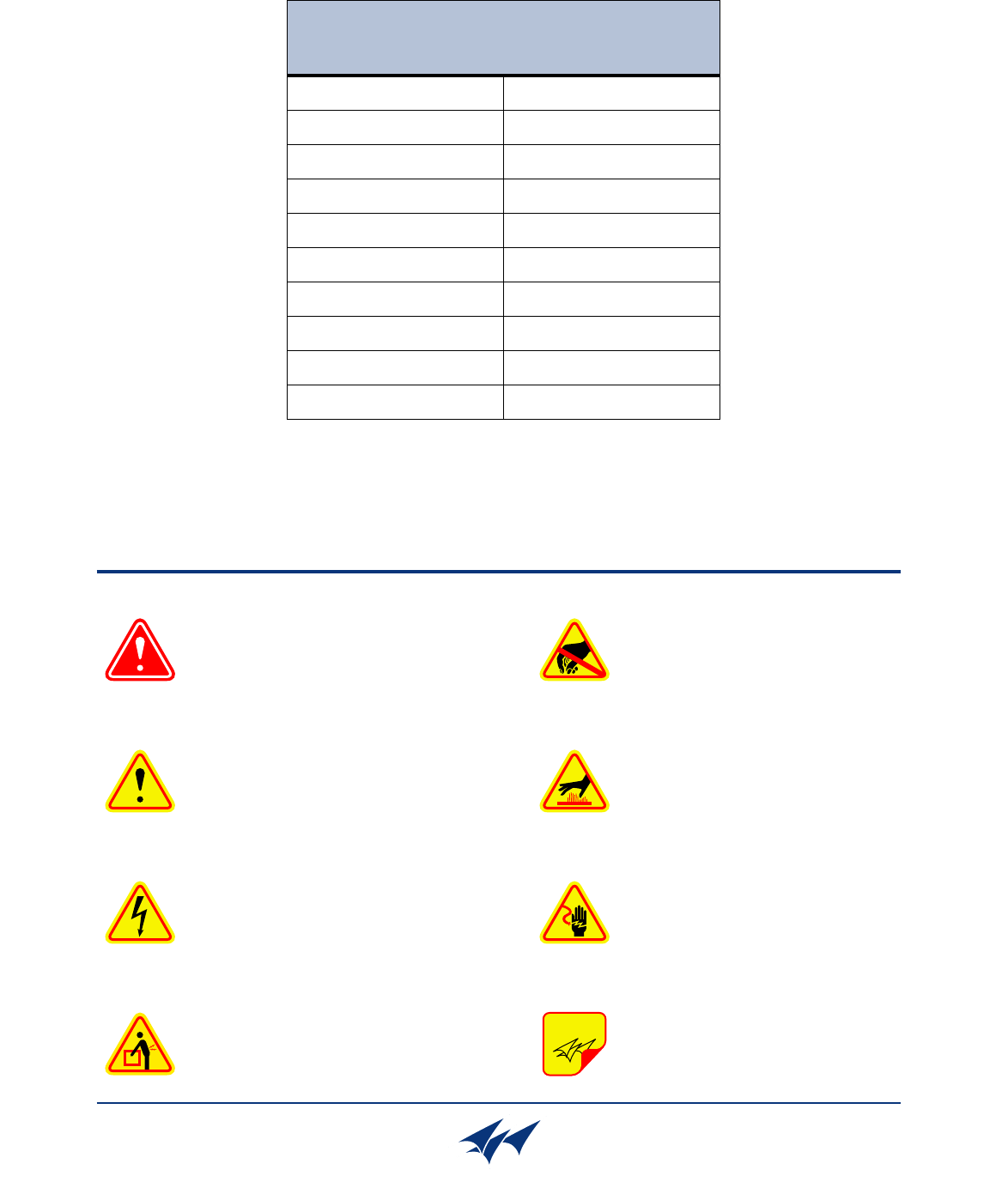
Symbols Commonly Used
WARNING
ESD Electrostatic Discharge
Hot Surface
Electrical Shock Hazard
Important Information
CAUTION or ATTENTION
High Voltage
Heavy Lifting
Bird Technologies Group TX RX Systems Inc.
NOTE
Manual Part Number 7-9469
Copyright © 2010 TX RX Systems, Inc.
First Printing: March 2009
Version Number Version Date
1 03/30/09
1.1 06/10/09
1.2 07/31/09
1.3 (RD) 07/31/09
1.4 (RD) 10/23/09
1.5 (RD) 10/28/09
1.6 (RD) 11/18/09
1.7 02/08/10

Contact Information
Changes to this Manual
Bird Technologies Group TX RX Systems Inc.
Sales Support at 716-217-3113
Customer Service at 716-217-3144
Technical Publications at 716-549-4700 extension 5019
We have made every effort to ensure this manual is accurate. If you discover any
errors, or if you have suggestions for improving this manual, please send your
comments to our Angola, New York facility to the attention of the Technical Publications
Department. This manual may be periodically updated. When inquiring about updates to
this manual refer to the manual part number and revision number on the revision page
following the front cover.
Table of Contents Manual 7-9469-1.7 02/08/10
Table of Contents
Overview............................................................................................................... 1
Down / Up Conversion......................................................................................... 1
Unpacking ............................................................................................................ 2
Installation............................................................................................................ 2
Location ............................................................................................................. 2
Installing the Booster .......................................................................................... 2
Connections........................................................................................................ 3
Antenna Isolation ............................................................................................... 3
Required Equipment ......................................................................................... 3
Measurement Procedure .................................................................................. 3
RF Exposure ........................................................................................................ 4
Functional Block Diagram Discussion .............................................................. 4
Downlink / Uplink Input Signals ........................................................................... 4
Downlink / Uplink Output Signals ........................................................................ 4
Channel Module .................................................................................................. 5
Operation.............................................................................................................. 5
Module LED’s ..................................................................................................... 5
Module Configuration.......................................................................................... 7
Command Buttons ............................................................................................ 9
Message Bars ................................................................................................... 9
Display / Interface Areas................................................................................... 9
Settings ........................................................................................................... 9
Filters ............................................................................................................. 9
Information ..................................................................................................... 9
Data ............................................................................................................... 9
Status............................................................................................................. 9
Additional Interactive Pages ........................................................................... 12
Admin........................................................................................................... 12
System ......................................................................................................... 12
Figures and Tables
Figure 1: The Down / Up Converter Process ....................................................... 1
Figure 2: Measuring Antenna Isolation................................................................. 4
Figure 3: Functional Block Diagram ..................................................................... 5
Figure 4A: Booster Cabinet Front View................................................................ 6
Figure 4B: Booster Cabinet Rear View ................................................................ 6
Figure 5: Enter Your Password ............................................................................ 7
Figure 6: Web-Page Interface Screen .................................................................. 8
Figure 7: Selecting a Module................................................................................ 9
Figure 8: Design Filter Interactive Display.......................................................... 12
Table 1: Specifications .......................................................................................... 1
Table 2: Channel Module Indicator LED’s............................................................. 7
Table 3: Connection Status Messages ............................................................... 10
Table 4: System Status Messages.......................................................... 10 and 11

Table of Contents Manual 7-9469-1.7 02/08/10
Appendixes
Appendix A: Front Panel Ethernet Connectivity .................................................13
Ethernet Connectivity ..........................................................................................13
Direct Connection ..............................................................................................13
Required Equipment ........................................................................................13
Procedure ........................................................................................................13
Networked Connection ......................................................................................14
Required Equipment ........................................................................................14
Procedure ........................................................................................................16
Appendix B: Changing Your Service Computers IP Address.............................17
For Class A Unintentional Radiators
This equipment has been tested and found to comply with the limits for a Class A digital device, pur-
suant to Part 15 of the FCC rules. These limits are designed to provide resonable protection against
harmful interference when the equipment is operated in a commercial environment. This equipment
generates, uses, and can radiate radio frequency energy and, if not installed and used in accordance
with the instruction manual, may cause harmful interference to radio communications. Operation of
this equipment in a residential area is likely to cause harmful interference in which the user will be
required to correct the interference at his own expense.
WARNING: Changes or modifications which are not expressly approved by
TXRX Systems Inc. could void the user’s authority to operate the equipment.
ATTENTION: This device complies with Part 15 of the FCC rules. Operation is subject
to the following two conditions: (1) this device may not cause harmful interference and
(2) this device must accept any interference received, including interference that may
cause undesired operation.
TX RX Systems Inc. Manual 7-9469-1.7 02/08/10 Page 1
OVERVIEW
Signal boosters extend radio coverage into areas
where abrupt propagation losses prevent reliable
communication. The system receives an RF signal,
raises its power level, and couples it to an antenna
so that it can be re-radiated. The TXRX model 611-
70A channelized signal booster is designed to
operate in the 450 to 512 MHz range. The system
is based on a module design with each module
capable of handling one uplink and one downlink
channel simultaneously. The size of the system
can be tailored to the customers needs by increas-
ing or decreasing the number of modules used.
Each module is bi-directional with one downlink
and one uplink signal branch. Each of the two
branches in a module are independently tunable to
their required pass frequency via software inter-
face. Specifications for the 611-70A family of chan-
nelized signal boosters are listed in Table1.
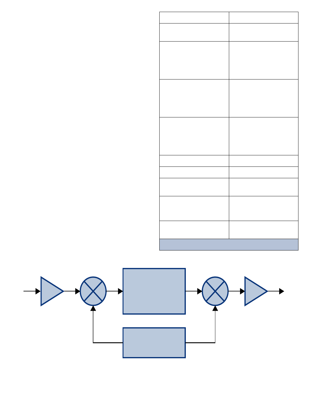
Down / Up Conversion
A channelized signal booster has much in common
with a superheterodyne (superhet) receiver. The
incoming signal is converted to a lower frequency
so that single channel selectivity can be obtained.
It is then filtered. Unlike the superhet receiver how-
ever, the signal is not demodulated. Instead, it is
up-converted back to its original frequency where it
is further amplified to reach a useful power level.
Intermediate
Frequency
Signal
Processing
1st Mixer 2nd Mixer
RF OutRF In
Local
Oscillator
Figure 1: The down converter / up converter process.
Frequency Range 450 - 512 MHz
Number of Carriers
per Channel
1 Uplink
1 Downlink
Nominal Passband Gain
Downlink
Uplink High Power
Uplink Low Power
120 dB
120 dB
100 dB
Channel Bandwidth
Standard 25 KHz;
can be programmed to
meet group delay require-
ments
(User Selectable)
Rated Power
Downlink
Uplink High Power
Uplink Low Power
+ 39 dBm ERP
+ 39 dBm ERP
+18 dBm ERP
Maximum Input Level -40 dBm
RF In/Out Impedance 50 Ohms
Alarms Form-C Contacts
Module LED’s
Power
90 - 250 VAC, 50/60 Hz
or
28 VDC (+/- 5%)
Operating Temperature
Range -30°C to +60°C
Table 1: Specifications
TX RX Systems Inc. Manual 7-9469-1.7 02/08/10 Page 2
Figure 1 shows a simplified block diagram that
illustrates the down/up conversion principle. An
incoming signal at (Freq IN) is amplified and
applied to the first mixer along with a signal from a
local oscillator (Freq LO). A third signal at an inter-
mediate frequency (Freq IF) is produced as a result
of the mixing. The intermediate frequency is given
by the following relationship:
(1) Freq IF = Freq IN - Freq LO
The IF signal from the mixer then passes through
digital filtering with single channel bandwidth
before being amplified and passed on to the sec-
ond mixer. The second mixer also receives the
same local oscillator signal (Freq LO). The result is
a mixing product frequency at the output of mixer
2. The output frequency (Freq OUT) is given by the
following relationship:
(2) Freq OUT = Freq IF + Freq LO
Substituting equation (1) for the “Freq IF” term in
equation (2) allows the “Freq LO” terms to be can-
celed yielding:
(3) Freq Out = Freq IN
The implication of equation (3) is that the frequency
stability of the signal that is processed by this type
of signal booster is not affected by the frequency
stability of the signal booster itself. Frequency sta-
bility depends only on the stability of the signal
source producing the signal to be boosted. A shift
in the LO frequency will cause the center of the fil-
ter bandwidth to move with respect to the signal.
For very narrow filter widths, the channel modules
LO may be locked to a high stability 10 MHz refer-
ence.
UNPACKING
It is important to report any visible damage to the
carrier immediately. It is the customers responsibil-
ity to file damage claims with the carrier within a
short period of time (1 to 5 days). Care should be
taken when removing the unit from the packing box
to avoid damage to the unit.
INSTALLATION
The following sub-sections of the manual discuss
general considerations for installing the booster. All
work should be performed by qualified personnel
and in accordance with local codes.
Location
The layout of the signal distribution system will be
the prime factor in determining the mounting loca-
tion of this unit. However, safety and serviceability
are also key considerations. The unit should be
located where it can not be tampered with by the
general public, yet is easily accessible to service
personnel. Also, consider the weight of the unit and
the possibility for injury if it should become
detached from its mounting for any reason.
The booster needs to be installed such that there
can be unobstructed air flow around the equip-
ment. Insure that the ventilation fans at the rear of
the module cabinet are unobstructed. The various
subassemblies within the module cabinet will stay
warm during normal operation so in the interest of
equipment longevity, avoid installation locations
that carry hot exhaust air or are continually hot.
Installing the Booster
The channelized booster system is shipped to the
customer in sections which must be assembled
into the rack before use. The sections which must
be installed in the rack for a standard system
include the module cabinet and filters. High-power
systems may also require the installation of a
hybrid combiner assembly. To install the channel-
ized booster into the rack perform the following
steps.
1) Install the filter assemblies at the bottom of the
rack using the supplied mounting screws. Face
the cable connectors towards the back of the
rack.
2) Install the module cabinet in the rack with the
supplied screws. Place the module cabinet
above the filters. Leave enough room above the
module cabinet to install a second cabinet if
required.
3) For high powered systems install the hybrid
combiner assembly in the rack using the sup-
plied mounting screws. For convenience its
best to place the combiner in the middle of the
rack between the filters and the module cabinet.
4) Interconnect the sections with the supplied
cables. The cable ends are tagged at the fac-
tory before shipment to help you make the cor-
rect interconnections.
TX RX Systems Inc. Manual 7-9469-1.7 02/08/10 Page 3
Connections
All RF cabling connections to the booster should
be made and checked for correctness prior to pow-
ering up the system. Connectors are available from
the filter assemblies for connection to the signal
distribution system. Make sure the correct branch
of the distribution system is connected to its corre-
sponding uplink/downlink connector or the system
will not work properly. Using high quality connec-
tors with gold center pins is advised. Flexible
jumper cables made of high quality coax are also
acceptable for connecting to rigid cable sections.
The booster is designed to be plugged into a single
phase AC line (90 - 250 VAC at 50/60 Hz) or a + 28
Volt DC source. A connector will be available at the
back panel of the module cabinet for connecting
either the AC or DC source voltage. At the time of
manufacture the equipment will be configured for
either AC or DC operation as per the customers
request and only one of the connectors, AC or DC,
will be available on the back panel. Additionally,
the AC connector has a 5 Amp fuse for protection.
Antenna Isolation
Antenna isolation between uplink and downlink
should be measured before connecting the signal
booster to the antenna system. This step is neces-
sary to insure that no conditions exist that could
possibly damage the signal booster and should not
be skipped for even the most thoroughly designed
system.
Just like the feedback squeal that can occur when
the microphone and speaker get too close together
in a public address system, a signal booster can
start to self oscillate. This can occur when the iso-
lation between the Uplink and Downlink antennas
does not exceed the signal boosters gain by at
least 15 dB. Oscillation will reduce the effective-
ness of the system and may possibly damage
amplifier stages. Isolation values are relatively
easy to measure with a spectrum analyzer and sig-
nal generator.
REQUIRED EQUIPMENT
The following equipment is required in order to per-
form the antenna isolation measurements.
1) Signal generator for the frequencies of interest
capable of a 0 dBm output level. Modulation is
not necessary.
2) Bird Technologies “Signal Hawk” spectrum ana-
lyzer which will cover the frequencies of interest
and is capable of observing signal levels down
to -100 dBm or better.
3) Double shielded coaxial test cables made from
RG142, RG55 or RG223 coaxial cable.
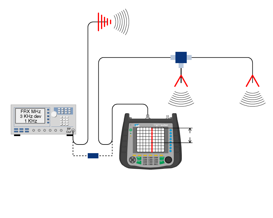
MEASUREMENT PROCEDURE
To measure the antenna isolation perform the fol-
lowing in a step-by-step fashion.
1) Set the signal generator for a 0 dBm output level
at the center frequency of the boosters pass-
band.
2) Set the spectrum analyzer for the same center
frequency and a sweep width equal to or just
slightly greater than the passband chosen ear-
lier in step 1.
3) Temporarily connect the test leads of the signal
generator and spectrum analyzer together
using a female barrel connector, see Figure 2.
Observe the signal on the analyzer and adjust
the input attenuator of the spectrum analyzer
for a signal level that just reaches the 0 dBm
level at the top of the graticule.
4) Referring to Figure 2, connect the generator
test lead to one side of the antenna system and
the spectrum analyzer to the other then observe
the signal level. The difference between the
observed level and 0 dBm is the isolation
between the sections. If the signal is too weak
to observe, the spectrum analyzer’s bandwidth
may have to be narrowed and it’s input attenua-
tion reduced. The isolation value measured
should exceed the signal booster’s gain figure
by at least 15 dB.
5) Repeat step 4 again with the signal generator
set at the passband edges in order to see if the
isolation is remaining relatively constant over
the complete width of the passband.
6) Repeat the isolation measurements if necessary
at other system passbands to determine the
overall minimum isolation value for the system.
Physical modification of the antenna system
maybe required in order to reach an acceptable
minimum value.
TX RX Systems Inc. Manual 7-9469-1.7 02/08/10 Page 4
RF EXPOSURE
To comply with FCC RF exposure compliance
requirements, a separation distance of at least 100
cm must be maintained between the antenna of
this device and all persons. This device must not
be co-located or operating in conjunction with any
other antenna or transmitter.
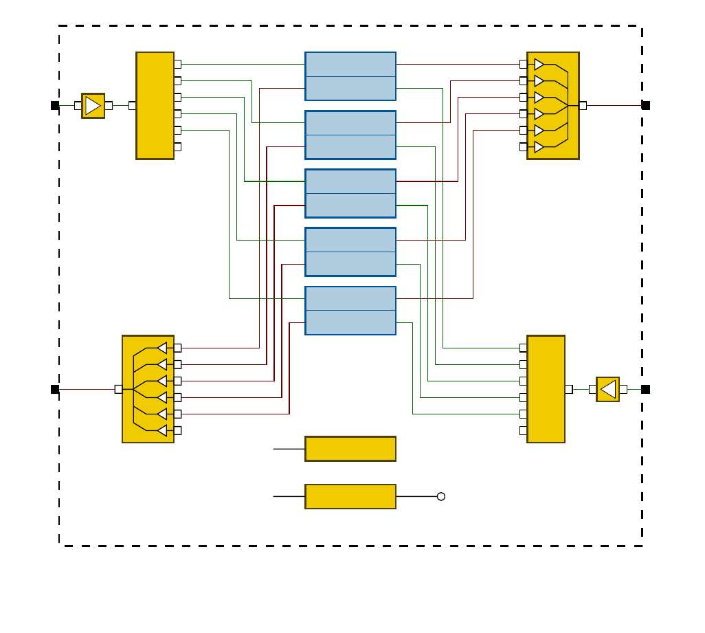
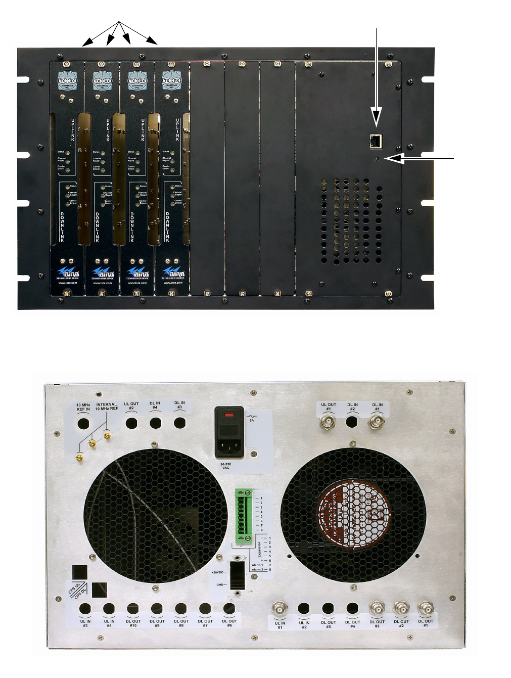
FUNCTIONAL BLOCK DIAGRAM
Figure 3 is the functional block diagram of the
standard channelized signal booster model 611-
70A. Figure 4A and 4B show the front and rear
views of the booster cabinet.
Downlink / Uplink Input Signals
Downlink and Uplink input signals are applied to a
distribution amplifier. This is an ultra-low noise high
linearity amplifier with a gain of 18.9 dB. Following
the distribution amp is a 6-way power divider which
is used to distribute the signal to individual channel
modules within the booster cabinet. Downlink sig-
nals are applied to the down converter board of a
downlink branch while uplink signals are applied to
the down converter board of an uplink branch.
Downlink / Uplink Output Signals
Downlink output signals leave the channel module
at the DL OUT connector and are applied to an
active combiner. The active combiner amplifies
and combines signals from multiple modules. Sig-
nals output from the active combiner are applied to
the filter assemblies. Uplink output signals leave
the channel module at the UL OUT connector and
are also applied to an active combiner. The active
combiner amplifies and combines signals from
multiple modules. Following the active combiner
are the filter assemblies.
The exact filter assemblies used in your channel-
ized booster system will depend upon the overall
communications system design and your particular
RF environment. A system level drawing will be
supplied with your booster which details the filter
assemblies used and their interconnections.
Signal Generator
External
Antenna
(YAGI)
Spectrum Analyzer
Isolation (dB)
Zero Loss
Reference
Internal
Signal Distribution
System
(Omni-directional
Antennas)
Figure 2: Typical test equipment interconnection for measuring antenna isolation.
TX RX Systems Inc. Manual 7-9469-1.7 02/08/10 Page 5
Channel Module
The channel modules are bi-directional with each
module containing one downlink branch and one
uplink branch. The branches are functionally identi-
cal because the same set of circuit boards are
used in each branch. The uplink and downlink
branches may be programmed to any frequency in
the appropriate band, 450-470, 470-491, or 491-
512 MHz. It is not recommended to program an
uplink and downlink to the same frequency or feed-
back may occur. Within the channel module, input
signals are down converted, digitized, and DSP fil-
tering is performed. Then the analog signal is rec-
reated and up converted to the original frequency.
OPERATION
Power is applied to the channelized booster by
plugging in the AC or DC power cord (depending
on how the system was configured for input
power). There is a Power-ON LED located on the
front of the unit (near the user interface connector)
which will illuminate when power is applied to the
cabinet. The ventilation fans at the rear of the cabi-
net will be continuously on when power is applied.
Module LED’s
There are six LED indicators on the front of each
channel module, 3 for the uplink branch and 3 for
the downlink branch. The function of each of these
indicator LED’s are listed in Table 2.
Downlink XXXX MHz
Uplink XXXX MHz
Downlink XXXX MHz
Uplink XXXX MHz
Downlink XXXX MHz
Uplink XXXX MHz
Downlink XXXX MHz
Uplink XXXX MHz
Downlink XXXX MHz
Uplink XXXX MHz
6-Way Power Divider
3-16676
6-Way Power Divider
3-16676
Active Combiner
3-22318
Distribution
Amp
3-22340
Distribution
Amp
3-22340
Control Module
Power Supply
To All
Channel
Modules
+28VDC to
Channel
Modules
Active Combiner
3-22318
From
Filters
To
Filters
To
Filters
From
Filters
Power
Source
Figure 3: Functional block diagram of the standard channelized signal booster.
Five channel system shown as an example.
TX RX Systems Inc. Manual 7-9469-1.7 02/08/10 Page 6
Figure 4B: Booster cabinet rear view.
Figure 4A: Booster cabinet front view (four channel system shown as an example).
User Interface Connector
Power ON
LED
Indicator
Modules
TX RX Systems Inc. Manual 7-9469-1.7 02/08/10 Page 7
Module Configuration
The channelized signal booster provides front
panel Ethernet connectivity that allows access to a
web-based interface for programming the individ-
ual modules. Programming will require connecting
your laptop computer to the User Interface connec-
tor on the front of the booster cabinet. Figure 4A
shows the interface connector (LAN). A standard
Ethernet crossover cable is used to make the con-
nection between your laptop and the booster cabi-
net. Refer to Appendix A at the back of this
manual for detailed instructions on how to properly
connect your computer to the LAN port of the
booster.
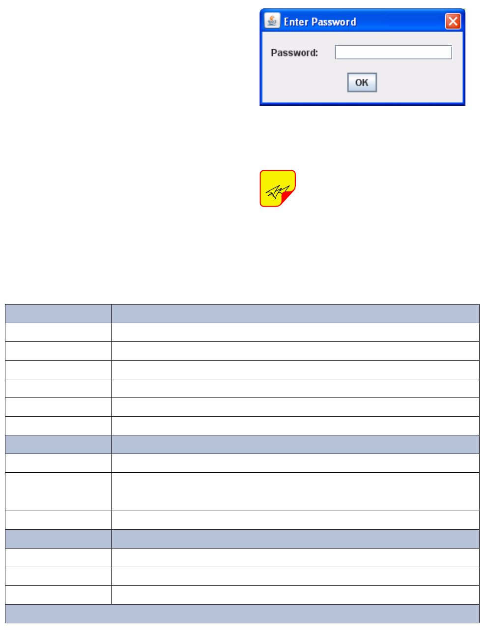
Once your laptop is properly connected to the sig-
nal booster, if password protection is enabled, the
password request box will appear in your web
browser as shown in Figure 5. Type in your pass-
word and press the OK button. The password box
will disappear and the web-based interface screen
will appear as shown in Figure 6.
Once your password has been
entered and validated a 15 minute
inactivity timer is started. If the user
does not make any changes to the
web page interface the system will re-
arm security once the inactivity timer
expires. The user will then need to re-
enter the password.
NOTE
Status LED
Green (flashing fast) Unit Identification (for several seconds only on command from User Interface)
Orange (slow flash) Unprogrammed unit (no settings set)
Off Unit disabled (no output from module)
Red (slow flash) External reference selected but is absent or not locked
Red (solid ON) Alarm of some kind (current or temp out of limits, LO not locked, filter not set)
Green (solid ON) all is OK
Channel Keyed
Slow Flash Unprogrammed unit (no settings set)
ON
Unit will transmit signal
if CTCSS and DCS disabled then signal present on input above carrier squelch threshold
Else if one is enabled then it means that the selected CTCSS or DCS code has been detected
OFF Unit will not transmit signal
Carrier Detect
Slow Flash Unprogrammed Unit (no settings set)
ON Signal present on input above carrier squelch threshold
OFF No signal present on input above carrier squelch threshold
Table 2: Channel Module Indicator LED’s
Figure 5: Enter your password.
TX RX Systems Inc. Manual 7-9469-1.7 02/08/10 Page 8
Password protection is disabled by default when
your system leaves the factory. To enable pass-
word protection for your system perform the follow-
ing steps;
1) Launch the web page interface in your web
browser.
2) Click the “Admin” tab at the top of the interface
screen (see figure 6).
3) Enter your password. Write your password
down somewhere for safe keeping in case you
forget it. If you do forget your password you will
need to contact Bird Technologies Group to
obtain a default password.
4) Click the submit button to apply the changes.
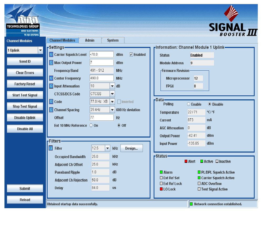
The web-based interface screen is divided into two
functional areas which include a row of command
buttons running down the left side of the screen as
well as display/interface areas on the right side of
the screen. The web-based interface is designed to
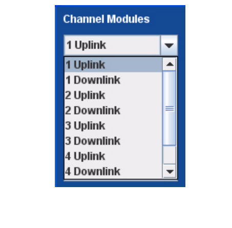
interact with one module at a time. The module
which has been selected for interaction appears in
the top of the drop down box in the upper left cor-
ner of the screen underneath the heading “Channel
Modules”. To change the selected module click on
the arrow to display the full drop down box, as
shown in Figure 7. Scroll down the list until the
desired module is highlighted and click on it.
Figure 6: The Web-Page Interface screen.
TX RX Systems Inc. Manual 7-9469-1.7 02/08/10 Page 9
COMMAND BUTTONS
Clicking on a command button (located on the
extreme left hand side of the screen) performs the
associated task immediately. The submit and
reload buttons in the bottom left corner allow any
changes you make to the display/interface boxes
to be downloaded to the booster. The submit and
reload buttons act like a trigger sending any
changes you made on the web-page interface
screen to the selected booster module, but only
after the button is pressed.
MESSAGE BARS
There are two message bars at the bottom of the
web-page screen. The rightmost message bar dis-
plays connection status messages and the leftmost
message bar displays system status messages.
The connection status messages reveal the rela-
tionship between the LAN interface and the control
board within the booster cabinet. Without a prop-
erly functioning connection you will not be able to
interface with the control board or individual mod-
ules. All of the possible connection status mes-
sages are listed in Table 3 along with a brief
description of what each message means. The
system status messages vary depending on what
aspect of the booster system you are interacting
with. All of the possible system status messages
are listed in Table 4.
DISPLAY/INTERFACE AREAS
The display/interface area of the web-based inter-
face is divided into five functional areas including;
Settings - this is a user interactive area where the
field engineer can program the operating charac-
teristics of the selected module. Each parameter in
the settings area can be changed by clicking in the
box and typing in the new values or by pointing at
an arrow to display a drop down box. Most of the
adjustable parameters have adjustment limitations
which can be displayed in a message box by click-
ing on the question mark symbol next to the
parameter. The parameters are self-explanatory.
Remember the changes you make are only appli-
cable to the selected channel module. After you
have made changes to the various parameters
press the “submit” command interface button
(lower left corner of the screen) in order to copy the
changes into the module itself.
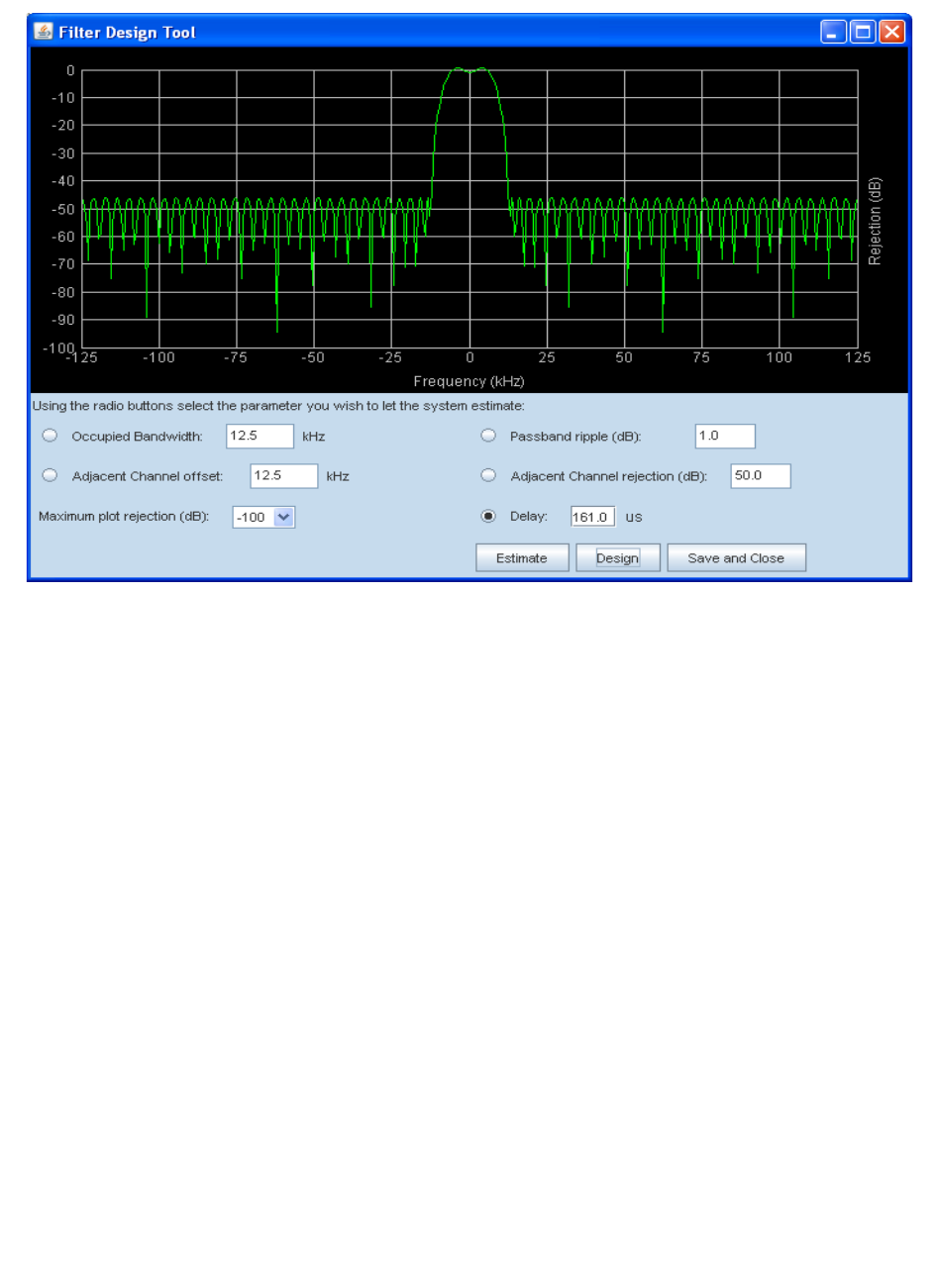
Filters - this area allows you to modify the charac-
teristics of the digital filtering used by the channel
module. Parameters that can be changed include
the occupied bandwidth, adjacent channel offset,
passband ripple, adjacent channel rejection, and
delay.
When the “Design Filter” button is pressed a cus-
tom design template will be displayed as shown in
Figure 8. Remember the changes you make are
only applicable to the selected channel module.
After you have made changes to the various
parameters press the “submit” command interface
button (lower left corner of the screen) in order to
copy the changes into the module itself.
Information - this area is non-interactive and is
used to display basic information about the
selected channel module.
Data - this area is also non-interactive and displays
detailed technical parameters. The polling function
can be changed between either enabled or dis-
abled. Click on the bubble next to the function to
change the polling status. In the example shown in
figure 6 the polling is currently disabled. To enable
polling you would point at the bubble next to the
enable label and right click.
Status - this area is used to give a quick overview
of eight channel module parameters. Each param-
eter can be in one of three states; alert, active or
inactive. Each state is color coded as shown in fig-
ure 6.
Figure 7: Selecting a module.

TX RX Systems Inc. Manual 7-9469-1.7 02/08/10 Page 10
Message Context
Ready to connect The Applet has finished loading and has not attempted to connect to the
control board.
Network connection established Upon successful connection to the control board.
Not connected The Applet either is not connected or has failed to connect to the control
board.
No network connection Unable to reconnect to the control board.
Table 3: Connection status messages.
Message Context
Obtained startup data successfully Connection to control board has been established and data and settings for
the active module uplink/downlink have been successfully obtained.
Failed to connect to booster Initial attempt to connect to the control board failed.
Network client restarting Reconnecting to the control board.
Network connection restarted Reconnected to the control board successfully.
The page was reloaded Successful reload of settings or data for a page (Admin, System, CPS)
Submitting network settings User clicked the “Submit” button to send the network settings to the control
board.
Failed to submit network settings An error occurred while sending network settings to the control board.
Network settings updated successfully The network settings have been sent and applied successfully.
Password settings updated successfully The password settings have been sent and applied successfully.
Failed to update password settings An error occurred while sending password settings to the control board.
Requesting device readings Requesting data from the control board for the active module (temperature,
current measurements, etc...)
Obtained device readings Obtained data successfully
Submitting system settings User clicked the “Submit” button to send the system settings to the control
board.
System settings submitted The system settings have been sent and applied successfully.
Failed to submit system settings An error occurred while sending system settings to the control board.
Data Sequencer : Error submitting query General communication message error.
Sending the factory reset command User clicked the “Factory Reset” button.
The factory reset command was sent The control board has restored factory default settings.
Sending the device ID command User clicked the “Send ID” button.
The device ID command was sent The control board has executed the “Send ID” command.
Sending the device clear errors command User clicked the “Clear Errors” button.
Table 4 (part 1): System status messages.

TX RX Systems Inc. Manual 7-9469-1.7 02/08/10 Page 11
Message Context
The device clear errors command was sent Errors have been cleared successfully.
Submitting the settings User clicked the “Submit” button on the channel modules page.
The settings have been submitted successfully The settings have been sent to the control board and saved successfully.
Reloading the admin values User clicked the “Reload” button on the admin page.
Reloading the system values User clicked the “Reload” button on the System page.
Reloading the CPS values User clicked the “Reload” button on the CPS page.
Starting the test signal with X deviation User clicked the “Start Test Signal” button.
Stopping the test signal User clicked the “Stop Test Signal” button.
Test signal started with X deviation The test signal has been started for the active channel module.
Test signal stopped The test signal was stopped.
Enabling module The user clicked the “Enable Uplink/Downlink” button.
Disabling module The user clicked the “Disable Uplink/Downlink” button.
Module enabled The module has been enabled successfully.
Module disabled The module has been disabled successfully.
Requesting startup data Polling channel module settings and data for the selected uplink/downlink.
Requesting device list Requesting a list of uplinks and downlinks from the control board.
The software failed to find any devices. Please
check your cables. No uplinks or downlinks have been found.
Obtained device list A device list has been gathered. initialization will continue.
Disabling all channel modules The user clicked the “Disable All” button.
Disable all modules command sent The command to disable all modules has been sent. Results will be dis-
played in a message box.
Failed to clear errors An error occurred while clearing errors.
Failed to restore factory settings An error occurred while restoring factory settings.
Failed to send device ID An error occurred while identifying a module uplink/downlink.
Failed to start the test signal An error occurred while starting the test signal.
Failed to stop the test signal An error occurred while stopping the test signal.
Failed to save settings An error occurred while saving settings.
Failed to acquire module list An error occurred while acquiring a list of uplink/downlinks.
Failed to enable module An error occurred while enabling a module uplink/downlink.
Failed to disable module An error occurred while disabling a module uplink/downlink.
Failed to load settings An error occurred while loading settings.
Error loading filter coefficients An error occurred while loading filter coefficients from a resource file.
Failed to acquire filter settings An error occurred while reading filter settings from a module uplink/down-
link.
Table 4 (part 2): System status messages.
TX RX Systems Inc. Manual 7-9469-1.7 02/08/10 Page 12
ADDITIONAL INTERACTIVE PAGES
In addition to interfacing with the individual channel
modules the web-based interface also provides
access to two additional areas of interaction includ-
ing Admin and System. Access to these additional
areas is through the tabs at the very top of the dis-
play/interactive area. When a tab is clicked the
page associated with that tab will be displayed and
you can interact with the functions.
Admin - the admin page allows the user to change
the boosters network settings and enable pass-
word protection for the web-based interface pro-
gram. The boxes on this page are interactive. To
make changes click inside the box and a cursor will
appear.
System - the system page lists the applet and con-
trol board software versions. A customer desig-
nated location name can be recorded and the
number of modules installed in the system is dis-
played. There is also a system logbook available
on this page.
Figure 8: The design filter interactive display screen.
TX RX Systems Inc. Manual 7-9469-1.7 02/08/10 Page 13
ETHERNET CONNECTIVITY
The front panel User Interface connector on the
booster provides for 10/100 BASE-T Ethernet con-
nection using the TCP-IP protocol. This product
feature allows access to a web-based interface for
programming the individual modules within the
booster. The web based interface requires a JAVA
runtime environment (version 1.6.0 or later) to be
installed on your laptop. The JAVA software can be
downloaded free of charge from the Sun Microsys-
tems website found at “http://java.com/en/down-
load/index.jsp”. The channelized booster is
shipped from the factory with a default IP address
of “192.168.1.1”.
Two connection schemes are discussed including
a direct connection from your laptop computer to
the booster front panel as well as connecting the
booster to a networked environment. A direct con-
nection (at the installation site) should be estab-
lished the first time you interface to the booster
using the fixed IP mentioned above. Once the ini-
tial communications are established the IP address
in the booster can be changed to permit a net-
worked connection (from a remote site such as
your office).
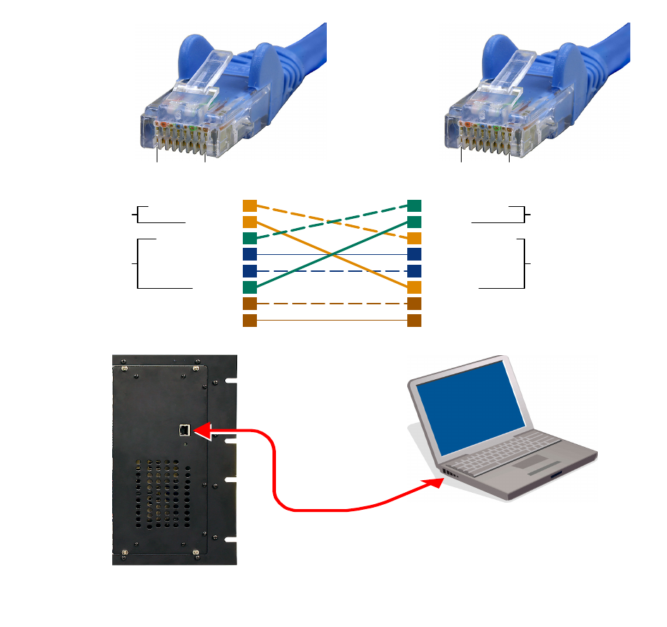
Direct Connection
Your initial connection to the booster system
should be a direct connection to the front panel
using an Ethernet crossover cable. Figure A1
shows the proper way to interconnect the equip-
ment as well as the pinout for a CAT-5 crossover
cable.
REQUIRED EQUIPMENT
Cat-5 Crossover Cable
Laptop Computer with a network interface card
installed. In addition, the JAVA run-time environ-
ment version 1.6.0 or later, and a web browser
such as Internet Explorer must also be installed on
the laptop.
PROCEDURE
To connect your laptop computer to the front panel
LAN port and access the web page interface, per-
form the following steps;
1) Insure the JAVA runtime environment software
is installed on your laptop.
2) Connect your laptop network port to the LAN
connector on the booster front panel using a
standard CAT-5 Crossover cable.
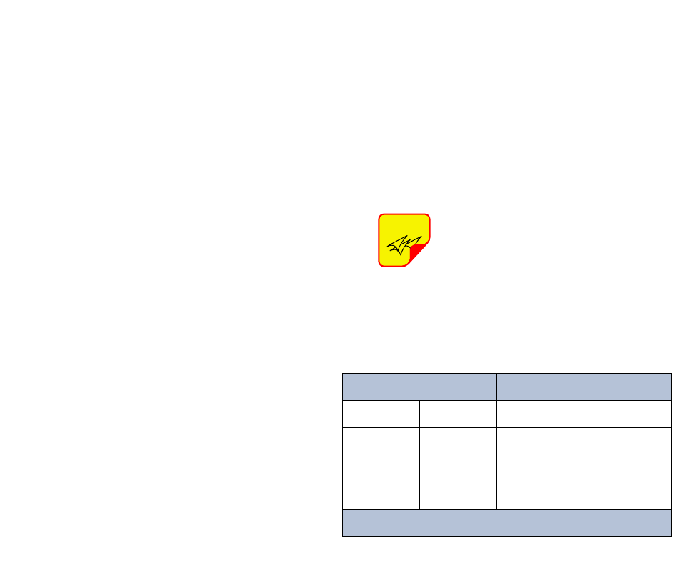
The front panel LAN connector
has two built-in bi-color status
LED’s which will aid you in estab-
lishing communications. The
meaning of each LED is shown in
Table A1.
3) The left-most (LINK) status LED built-in to the
LAN port connector should illuminate amber or
green indicating that a good physical connec-
tion is established between your computer and
the booster.
4) Insure that your laptop’s IP address is compati-
ble with the default address of the signal
booster system. This may require changes be
made to the Ethernet adaptor address on your
laptop (refer to Appendix B). Your laptop’s IP
address will need to be set to “192.168.1.2”
along with a subnet mask of “255.255.255.0”.
The right-most (ACTIVITY) status LED built-in
to the LAN port connector will turn amber or
green indicating good TCP-IP communications
are established between the laptop and the
booster.
NOTE
APPENDIX A
Front Panel Ethernet Connectivity
LINK LED (left side) ACTIVITY LED (right side)
Color Meaning Color Meaning
Off No Link Off No Activity
Amber 10 Mbps Amber Half-Duplex
Green 100 Mbps Green Full-Duplex
Table A1: LAN port status LED’s
TX RX Systems Inc. Manual 7-9469-1.7 02/08/10 Page 14
5) Launch your web browser software on the lap-
top.
6) In your web browsers address box type-in the
address of the booster “http://192.168.1.1” and
press the ENTER key. The web page interface
to the booster should appear in your laptop’s
browser window. When you launch the web
page you may notice that the JAVA applet will
load first.
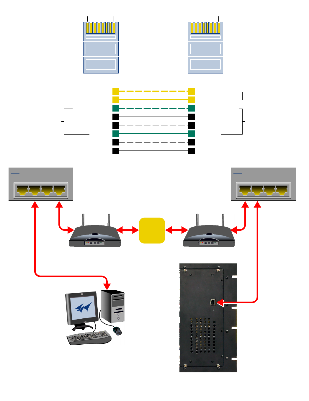
Networked Connection
Before attempting a networked connection to the
signal booster system consult with your IT support
personnel for information concerning the correct IP
address to use and any additional connectivity
issues such as firewalls. Once you have the correct
IP address you will need to direct connect to the
booster system as discussed in the earlier section
of this appendix and reconfigure the booster LAN
port with this new address. You can then connect
the signal booster system using a straight-through
CAT-5 cable to the networked environment and
interface to it from a remote computer. Figure A2
shows the proper way to interconnect the equip-
ment for a networked connection as well as the
pinout for a straight-thru CAT-5 cable.
REQUIRED EQUIPMENT
Cat-5 Straight-thru Cable
Laptop Computer with a network interface card
installed. In addition, the JAVA run-time environ-
1
4
7
6
3
5
8
2
1
4
7
6
3
5
8
2
Orange/White
Orange
Green/White
Blue
Blue/White
Green
Brown/White
Brown
Green/White
Green
Orange/White
Blue
Blue/White
Orange
Brown/White
Brown
T
ransmit (1 & 2)
Receive (3 & 6) Transmit (3 & 6)
Receive (1& 2)
Pins 4, 5, 7 and 8 are not used
Pin Pin
CAT-5 Cross-Over Cable
18 18
Figure A1: Direct connection to the booster using crossover cable.
TX RX Systems Inc. Manual 7-9469-1.7 02/08/10 Page 15
1
4
7
6
3
5
8
2
1
4
7
6
3
5
8
2
Orange/White
Orange
Green/White
Blue
Blue/White
Green
Brown/White
Brown
Orange/White
Orange
Green/White
Blue
Blue/White
Green
Brown/White
Brown
Transmit (1 & 2)
Receive (3 & 6) Transmit (3 & 6)
Receive (1& 2)
Pins 4, 5, 7 and 8 are not used
Pin Pin
1234
4 Port Ethernet Hub
1234
4 Port Ethernet Hub
CAT-5
Straight-Through
Cable
Modem/Router Modem/Router
Remote PC System
Internet
18 18
Figure A2: WAN connection to the booster using straight-through cable.

TX RX Systems Inc. Manual 7-9469-1.7 02/08/10 Page 16
ment version 1.6.0 or later, and a web browser
such as Internet Explorer must also be installed on
the laptop.
PROCEDURE
Before a networked connection can be established,
the booster LAN Port must be changed to an IP
address that’s compatible with your network. If you
are unsure how to determine this address check
with your IT support personnel. To connect the
booster LAN port to a networked environment and
access the web page interface, perform the follow-
ing steps;
1) Change the boosters LAN port IP address. To
do this, direct connect your laptop to the
booster as discussed in the earlier section of
this appendix titled “Direct Connection” and fol-
low steps 1 through 4.
2) Launch the configuration Applet in your web
browser.
3) Click the “Admin” tab at the top of the interface
display screen.
4) To be safe, take note of the settings currently
displayed.
5) Select the “User Static IP” radio button.
6) Enter the following settings provided by your
network administrator;
A) IP Address
B) Subnet Mask
C) Gateway Address
7) Click the “Submit” button to apply the changes.
8) Once the changes have been successfully
applied close your web browser.
9) Launch the configuration Applet in your web
browser using the newly entered IP address.
TX RX Systems Inc. Manual 7-9469-1.7 02/08/10 Page 17
When you initially direct connect your laptop ser-
vice computer to the booster it will be necessary to
change the computers IP address. The procedure
for doing this varies depending upon your operat-
ing system. As an example, this appendix illus-
trates how to make the change using the Microsoft
XP operating system. The procedure for other
operating systems will vary slightly from this exam-
ple. Consult with your IT support personnel if
needed. To change the IP address (assuming the
Microsoft XP operating system is being used) per-
form the following in a step-by-step fashion;
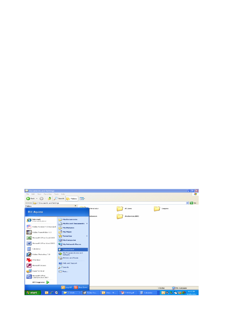
1) Select “Start” from the status menu.
2) Single click the “Control Panel” choice from the
“Start” pop-up menu as shown in Figure B1.
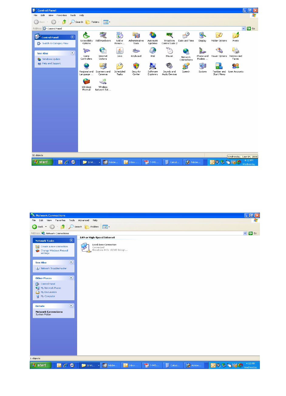
3) From the “Control Panel” icon selections double
click on the “Network Connections” icon. Refer
to Figure B2.
4) When the “Network Connections” folder opens
double click on the “Local Area Connection”
icon. See Figure B3.
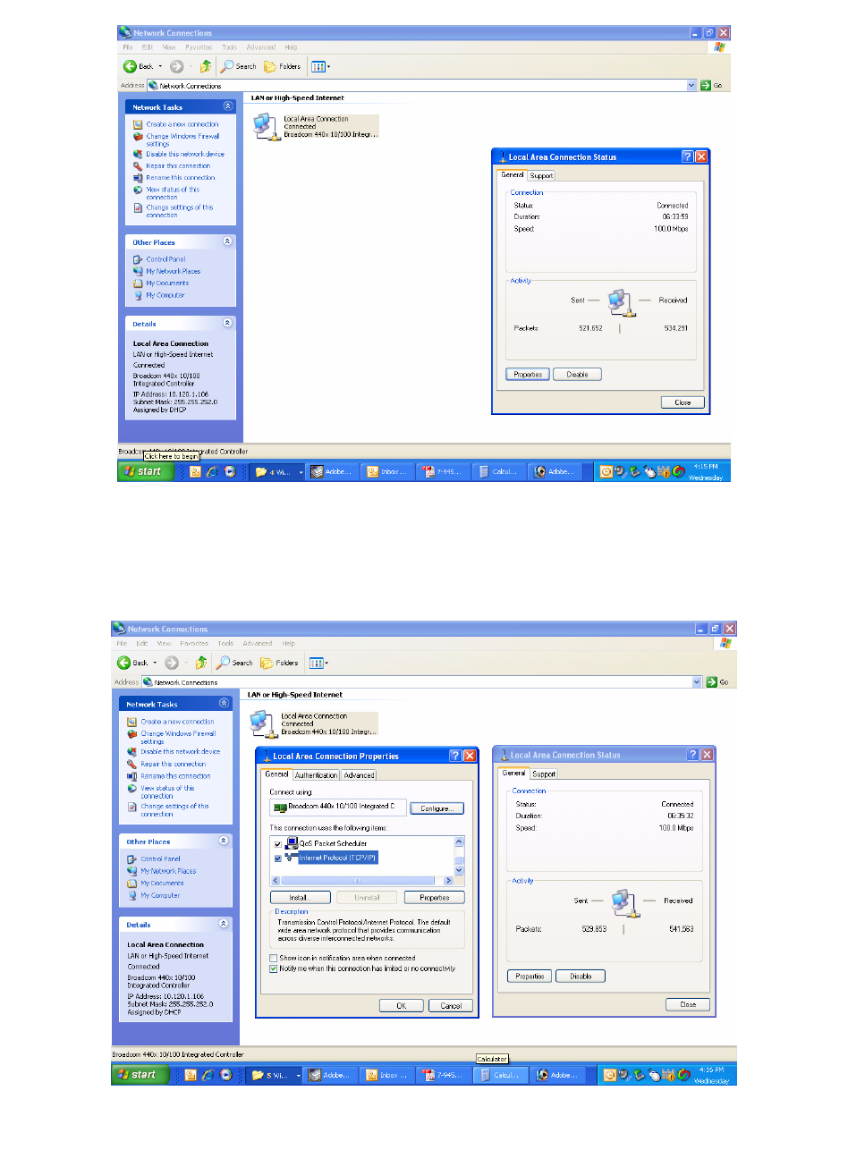
5) The “Local Area Connection Status” box will
open. Single click the “Properties” tab as shown
in Figure B4. Note: If you do not have the cable
connected between the service computer and
the booster front panel the “Local Area Connec-
tion Status” box will not open. Instead proceed
to step 6.
6) The “Local Area Connection Properties” box will
open. Use the arrow buttons to scroll down the
list until the “Internet Protocol (TCP/IP)” choice
is highlighted as shown in Figure B5. Click the
“Properties” tab at the right-center of the box.
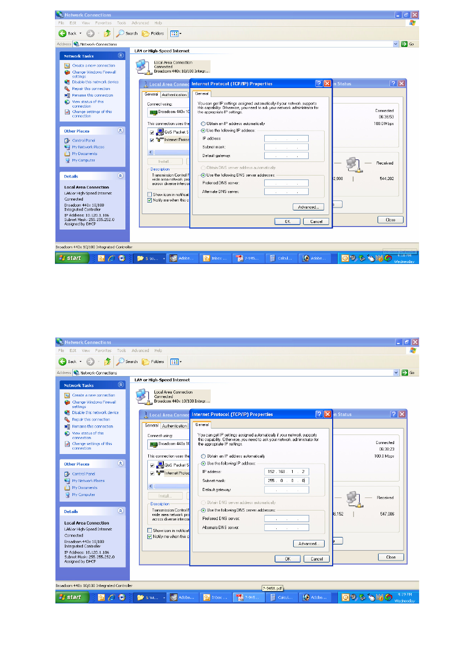
7) Select the “Use the following IP address” bub-
ble. Make sure the circle is filled-in. Refer to
Figure B6.
8) Enter the new IP address and subnet mask val-
ues as shown in Figure B7. To interface your
computer to the signal booster use an IP
address of “192.168.1.2” and a subnet mask of
“ 255.255.255.0”.
9) Click on the “OK” tab to initiate the changes.
This completes the procedure. Close any open
boxes.
APPENDIX B
Changing Your Service Computers IP Address
Figure B1: Choose the “Control panel” icon.
TX RX Systems Inc. Manual 7-9469-1.7 02/08/10 Page 18
Figure B2: Select the “Network Connections” icon.
Figure B3: Select the “Local Area Connection” icon.
TX RX Systems Inc. Manual 7-9469-1.7 02/08/10 Page 19
Figure B4: Select the “Properties” tab.
Figure B5: Make sure the “Internet Protocol (TCP/IP)” choice is highlighted. Then select “OK”.
TX RX Systems Inc. Manual 7-9469-1.7 02/08/10 Page 20
Figure B6: Select “Use the Following IP Address”.
Figure B7: Enter the new IP Address and Subnet mask Values.

TX RX Systems Inc. Manual 7-9469-1.7 02/08/10 Page 21
Return Loss vs. VSWR
Return Loss VSWR
30 1.06
25 1.11
20 1.20
19 1.25
18 1.28
17 1.33
16 1.37
15 1.43
14 1.50
13 1.57
12 1.67
11 1.78
10 1.92
92.10
Watts to dBm
Watts dBm
300 54.8
250 54.0
200 53.0
150 51.8
100 50.0
75 48.8
50 47.0
25 44.0
20 43.0
15 41.8
10 40.0
537.0
436.0
334.8
233.0
130.0
dBm = 10log P/1mW
Where P = power (Watt)
Insertion Loss
Input Power (Watts)
50 75 100 125 150 200 250 300
325 38 50 63 75 100 125 150
2.5 28 42 56 70 84 112 141 169
232 47 63 79 95 126 158 189
1.5 35 53 71 88 106 142 177 212
140 60 79 99 119 159 199 238
.5 45 67 89 111 134 178 223 267
Output Power (Watts)
Insertion Loss
Free Space Loss
Distance (miles)
.25 .50 .75 1 2 5 10 15
150 68 74 78 80 86 94 100 104
220 71 77 81 83 89 97 103 107
460 78 84 87 90 96 104 110 113
860 83 89 93 95 101 109 115 119
940 84 90 94 96 102 110 116 120
1920 90 96 100 102 108 116 122 126
Free Space Loss (dB)
Free space loss = 36.6 + 20log D + 20log F
Where D = distance in miles and F = frequency in MHz
Frequency (MHz)

TX RX Systems Inc. Manual 7-9469-1.7 02/08/10 Page 22
8625 Industrial Parkway, Angola, NY 14006 Tel: 716-549-4700 Fax: 716-549-4772 sales@birdrf.com www.bird-technologies.com