Bird Technologies Group 6138X SBIII Digital Signal Booster User Manual 9485S1 1 9 1
Bird Technologies Group SBIII Digital Signal Booster 9485S1 1 9 1
User Manual

TX RX Systems Inc. Manual 7-9485-1.9.1 10/26/17 Page 1
YOU'RE HEARD, LOUD AND CLEAR.
8625 Industrial Parkway, Angola, NY 14006 Tel: 716-549-4700 Fax: 716-549-4772 sales@birdrf.com www.bird-technologies.com
Installation and Operation Manual for
the SBIII Digital Signal Booster
Model 6138X
Manual Part Number
7-9485
DIGITAL TECHNOLOGY
WARNING: This is NOT a consumer device. It is designed for installation by FCC Lic-
ensees and Qualified Installers. You must have an FCC license or express consent
of an FCC Licensee to operate this device. This booster can be configured as either a
Class A or Class B signal booster. If configured as a Class B signal booster (as defined
in 47 CFR 90.219), you MUST register this signal booster online at www.fcc.gov/signal-
booster/registration. Unauthorized use may result in significant forfeiture penalties,
including penalties in excess of $100,000 for each continuing violation.
WARNING: This is NOT a CONSUMER device. It is designed for installation by an
installer approved by an ISED licensee. You MUST have an ISED LICENCE or the
express consent of an ISED licensee to operate this device.
AVERTISSEMENT: Ce n'est PAS un appareil CONSOMMATEUR. Il est conçu pour être
installé par un installateur agréé par un détenteur de licence ISED. Vous DEVEZ avoir
une LICENCE ISED ou le consentement exprès d'un détenteur de licence ISED pour
utiliser cet appareil.

TX RX Systems Inc. Manual 7-9485-1.9.1 10/26/17 Page 2
Warranty
This warranty applies for one year from shipping date.
TX RX Systems Inc. warrants its products to be free from defect in material and workmanship at the time of shipment.
Our obligation under warranty is limited to replacement or repair, at our option, of any such products that shall have
been defective at the time of manufacture. TX RX Systems Inc. reserves the right to replace with merchandise of
equal performance although not identical in every way to that originally sold. TX RX Systems Inc. is not liable for dam-
age caused by lightning or other natural disasters. No product will be accepted for repair or replacement without our
prior written approval. The purchaser must prepay all shipping charges on returned products. TX RX Systems Inc.
shall in no event be liable for consequential damages, installation costs or expense of any nature resulting from the
purchase or use of products, whether or not they are used in accordance with instructions. This warranty is in lieu of all
other warranties, either expressed or implied, including any implied warranty or merchantability of fitness. No repre-
sentative is authorized to assume for TX RX Systems Inc. any other liability or warranty than set forth above in con-
nection with our products or services.
TERMS AND CONDITIONS OF SALE
PRICES AND TERMS:
Prices are FOB seller’s plant in Angola, NY domestic packaging only, and are subject to change without notice. Fed-
eral, State and local sales or excise taxes are not included in prices. When Net 30 terms are applicable, payment is
due within 30 days of invoice date. All orders are subject to a $100.00 net minimum.
QUOTATIONS:
Only written quotations are valid.
ACCEPTANCE OF ORDERS:
Acceptance of orders is valid only when so acknowledged in writing by the seller.
SHIPPING:
Unless otherwise agreed at the time the order is placed, seller reserves the right to make partial shipments for which
payment shall be made in accordance with seller’s stated terms. Shipments are made with transportation charges col-
lect unless otherwise specified by the buyer. Seller’s best judgement will be used in routing, except that buyer’s routing
is used where practicable. The seller is not responsible for selection of most economical or timeliest routing.
CLAIMS:
All claims for damage or loss in transit must be made promptly by the buyer against the carrier. All claims for shortages
must be made within 30 days after date of shipment of material from the seller’s plant.
SPECIFICATION CHANGES OR MODIFICATIONS:
All designs and specifications of seller’s products are subject to change without notice provided the changes or modifi-
cations do not affect performance.
RETURN MATERIAL:
Product or material may be returned for credit only after written authorization from the seller, as to which seller shall
have sole discretion. In the event of such authorization, credit given shall not exceed 80 percent of the original pur-
chase. In no case will Seller authorize return of material more than 90 days after shipment from Seller’s plant. Credit
for returned material is issued by the Seller only to the original purchaser.
ORDER CANCELLATION OR ALTERATION:
Cancellation or alteration of acknowledged orders by the buyer will be accepted only on terms that protect the seller
against loss.
NON WARRANTY REPAIRS AND RETURN WORK:
Consult seller’s plant for pricing. Buyer must prepay all transportation charges to seller’s plant. Standard shipping pol-
icy set forth above shall apply with respect to return shipment from TX RX Systems Inc. to buyer.
DISCLAIMER
Product part numbering in photographs and drawings is accurate at time of printing. Part number labels on TX RX
products supersede part numbers given within this manual. Information is subject to change without notice.
Bird Technologies Group TX RX Systems Inc.
TX RX Systems Inc. Manual 7-9485-1.9.1 10/26/17 Page 3
Symbols Commonly Used
WARNING
ESD Electrostatic Discharge
Hot Surface
Electrical Shock Hazard
Important Information
CAUTION or ATTENTION
High Voltage
Heavy Lifting
Bird Technologies Group TX RX Systems Inc.
NOTE
Manual Part Number 7-9485
Copyright © 2017 TX RX Systems, Inc.
First Printing: May 2011
Version Number Version Date
1 05/16/11
1.4 07/25/11
1.6 09/02/11
1.7 09/12/11
1.8 09/16/11
1.9 09/26/17
1.9.1 10/26/17

TX RX Systems Inc. Manual 7-9485-1.9.1 10/26/17 Page 4
Table of Contents
Overview .............................................................................................................. 7
Down / Up Conversion ........................................................................................ 8
Unpacking............................................................................................................ 9
Installation ........................................................................................................... 9
Location ............................................................................................................. 9
Mounting ............................................................................................................ 9
Connections ....................................................................................................... 9
Antenna Isolation ............................................................................................. 10
Required Equipment....................................................................................... 11
Measurement Procedure ................................................................................ 11
RF Exposure (Exposition RF) ......................................................................... 12
Signal Flow Block Diagram ............................................................................. 12
Uplink and Downlink Input Signals.................................................................... 12
Channel Module................................................................................................ 14
Uplink and Downlink Output Signals ................................................................. 15
Operation ........................................................................................................... 15
Subassembly LED’s ........................................................................................ 15
Communicating With The Booster .................................................................. 15
System Summary Submenu ............................................................................. 15
Control Panel Submenu .................................................................................... 16
Filters Tab ....................................................................................................... 16
Filter Detail Tab............................................................................................... 17
Design Button................................................................................................ 18
Status Area ................................................................................................... 18
Link Tab .......................................................................................................... 19
Command Buttons........................................................................................ 19
Link and Settings Area ................................................................................. 20
Status Area................................................................................................... 20
System Tab ...................................................................................................... 21
Oscillation Detection....................................................................................... 22
Class B Enable ............................................................................................... 22
Network Configuration Submenu ...................................................................... 22
User Administration Submenu .......................................................................... 23
SNMP Configuration Submenu ......................................................................... 23
Initial SNMP Setup.......................................................................................... 24
SNMP Manager Example................................................................................ 25
Creating an alarm for testing purposes ......................................................... 25
TX RX Systems Inc. Manual 7-9485-1.9.1 10/26/17 Page 5
Figures and Tables
Figure 1: The Down / Up Converter Process .......................................................9
Figure 2: Cabinet Mounting ...............................................................................10
Figure 3: Measuring Antenna Isolation ...............................................................11
Figure 4: Signal Flow Block Diagram..................................................................12
Figure 5: Booster Cabinet Front View.................................................................13
Figure 6: Enet Connector....................................................................................15
Figure 7: System Summary Submenu................................................................16
Figure 8: The Filter Summary Tab ......................................................................17
Figure 9: Class A Limit Exceeded Warning Message.........................................17
Figure 10: Filter Detail Tab..................................................................................18
Figure 11: Invalid Filter Settings Warning Message............................................18
Figure 12: The Design Filter Display...................................................................19
Figure 13: The Link Tab ......................................................................................20
Figure 14: The System Tab.................................................................................21
Figure 15: Starting Class B Operation Message ................................................22
Figure 16: Network Configuration Message........................................................22
Figure 17: User Administration Submenu...........................................................23
Figure 18: SNMP Configuration Submenu..........................................................24
Figure 19: SNMP Manager Example ..................................................................25
Table 1: Model number nomenclature...................................................................7
Table 2: Specifications ..........................................................................................8
Table 3: Subassembly LED Descriptions ............................................................14
Appendixes
Appendix A: Front Panel Ethernet Connectivity .................................................27
Ethernet Connectivity...........................................................................................27
Direct Connection ..............................................................................................27
Required Equipment ........................................................................................27
Procedure ........................................................................................................27
Networked Connection.......................................................................................28
Required Equipment ........................................................................................29
Procedure ........................................................................................................30
Appendix B: Changing Your Service Computers IP Address .............................31

TX RX Systems Inc. Manual 7-9485-1.9.1 10/26/17 Page 6
For Class A Unintentional Radiators
This equipment has been tested and found to comply with the limits for a Class A digital device, pursuant to Part
15 of the FCC rules. These limits are designed to provide reasonable protection against harmful interference
when the equipment is operated in a commercial environment. This equipment generates, uses, and can radiate
radio frequency energy and, if not installed and used in accordance with the instruction manual, may cause harm-
ful interference to radio communications. Operation of this equipment in a residential area is likely to cause harm-
ful interference in which the user will be required to correct the interference at his own expense.
Pour Classe-A Radiateurs Involontaires
Cet équipement a été testé et jugé conforme avec les limites de la Classe-A des appareils numériques, suivants
à la Partie 15 des règlements de la FCC. Ces limites sont conçues pour fournir une protection raisonnable contre
les interférences dangereuses lorsque l'équipement est utilisé dans un environnement commercial. Cet équipe-
ment génère, utilise et peut émettre des fréquences radio et, s'il n'est pas installé et utilisé conformément aux
instructions du manuel, ceci peut causer des interférences dangereuses aux communications radio. Le fonction-
nement de cet équipement dans une zone résidentielle est susceptible de causer des interférences mauvaises
dans lequel l'utilisateur sera tenu pour responsable de corriger l'interférence à sa propre discrétion.
WARNING: Changes or modifications which are not expressly approved by TXRX Systems
Inc. could void the user’s authority to operate the equipment.
AVERTISSEMENT: Les changements ou modifications qui ne sont pas approuvés par
TXRX Systems Inc. pourrait annuler l'autorité de l'utilisateur de faire fonctionner l'équipement.
ATTENTION: This device complies with Part 15 of the FCC rules. Operation is subject to the following
two conditions: (1) this device may not cause harmful interference and (2) this device must accept any
interference received, including interference that may cause undesired operation.
ATTENTION : Cet appareil est conforme à la Partie 15 des règlements de la FCC. L'opération doit se
conformer aux deux conditions suivantes: (1) cet appareil ne peut causer d'interférences nuisibles et
(2) cet appareil doit accepter toute interférence reçue, y compris les interférences qui peuvent provo-
quer un fonctionnement indésirable.

TX RX Systems Inc. Manual 7-9485-1.9.1 10/26/17 Page 7
OVERVIEW
Signal boosters extend radio coverage into areas
where abrupt propagation losses prevent reliable
communication. The system receives an RF signal,
raises its power level, and couples it to an antenna
so that it can be re-radiated. The TXRX model
6138X family of channelized signal boosters is
designed to operate in either the 700 or 800 MHz
range. Dual band models are available that include
both 700 and 800 MHz systems in the same enclo-
sure box. The system is based on a module design
with each module capable of handling 14 or 30 car-
riers in the uplink and downlink direction. The sig-
nal booster is available in a variety of
configurations as shown in Table 1. The product
model number is used to describe each configura-
tion available. Model number nomenclature is
described in table 1.
The size of the system can be tailored to the cus-
tomers needs by increasing or decreasing the
number of carriers used. Each module is bi-direc-
tional with one downlink and one uplink signal
branch. Each of the two branches in a module are
independently tunable to their required pass fre-
quencies via software interface. System specifica-
6138X-XX-YY-UD-Z-Options (nomenclature breakdown)
6138X Designates product as 700 - 800 MHz channelized signal booster
XX
Designates operating frequency band
9A = 806 - 869 MHz
3B = 763 - 805 MHz
3G = 763 - 869 MHz
YY
Designates how many modules used and number of filters available
A = 1 module with 14 filters
B = 1 module with 30 filters
AA = 2 modules with 14 filters each
BB = 2 modules with 30 filters each
AB = 1 module (700 MHz) with 14 filters and 1 module (800 MHz) with 30 filters
BA = 1 module (700 MHz) with 30 filters and 1 module (800 MHz) with 14 filters
UD
Designates the type of output for the uplink and downlink
HH = high power uplink and downlink
HL = high power uplink and low power downlink
LH = low power uplink and high power downlink
LL = low power for both uplink and downlink
FH = fiber output uplink and high power downlink
FL = fiber output uplink and low power downlink
HF = high power uplink and fiber output downlink
LF = low power uplink and fiber output downlink
FF = fiber uplink and fiber downlink
Z
Designates mounting style
RM = 19” rack mount
G1 = Painted enclosure
G2 = Stainless steel enclosure
Options
Designates the options that have been added
Blank = no options added
N = NFPA compliant (National Fire Protection Association)
P = 10 MHz high precision reference
D = -48 VDC
Q = Fiber input downlink only
R = Fiber input uplink only
S = Fiber input downlink and uplink
Table 1: Model number nomenclature.

TX RX Systems Inc. Manual 7-9485-1.9.1 10/26/17 Page 8
tions for the 6138X family of channelized signal
boosters are listed in Table 2.
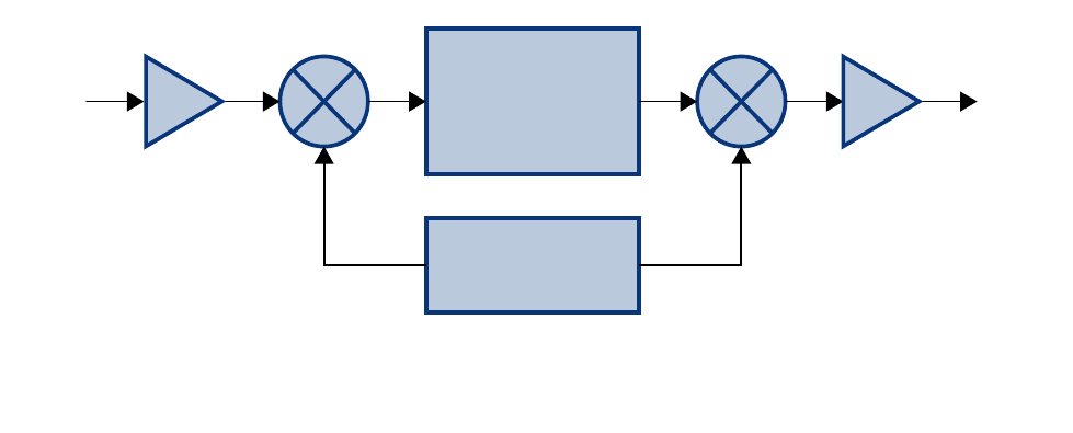
Down / Up Conversion
A channelized signal booster has much in common
with a superheterodyne (superhet) receiver. The
incoming signal is converted to a lower frequency
so that single channel selectivity can be obtained.
It is then filtered. Unlike the superhet receiver how-
ever, the signal is not demodulated. Instead, it is
up-converted back to its original frequency where it
is further amplified to reach a useful power level.
Figure 1 shows a simplified block diagram that
illustrates the down/up conversion principle. An
incoming signal at (Freq IN) is amplified and
applied to the first mixer along with a signal from a
local oscillator (Freq LO). A third signal at an inter-
mediate frequency (Freq IF) is produced as a result
of the mixing. The intermediate frequency is given
by the following relationship:
(1) Freq IF = Freq IN - Freq LO
The IF signal from the mixer then passes through
digital filtering with single channel bandwidth
before being amplified and passed on to the sec-
ond mixer. The second mixer also receives the
same local oscillator signal (Freq LO). The result is
a mixing product frequency at the output of mixer 2.
The output frequency (Freq OUT) is given by the
following relationship:
(2) Freq OUT = Freq IF + Freq LO
Substituting equation (1) for the “Freq IF” term in
equation (2) allows the “Freq LO” terms to be can-
celed yielding:
(3) Freq Out = Freq IN
Frequency Range (MHz)
763 - 775 and 793 - 805 (units sold in USA)
806 - 824 and 851 - 869 (units sold in USA)
764 - 776 and 794 - 806 (units sold in Canada)
806 - 824 and 851 - 869 (units sold in Canada)
Number of Carriers per Module
Low Density Model
High Density Model
14 uplink and downlink
30 uplink and downlink
Gain
Low Power Version
High Power Version
80 dB (min)
95 dB (min)
Maximum RF Bandwidth
700 MHz module
800 MHz module
12 MHz
15 MHz
Output Level
Low Power
High Power
-30 to 10 dBm composite
-15 to 32 dBm composite
Maximum Continuous Input Level Operational: -20 dBm
Static w/o damage: -10dBm
RF In/Out Impedance 50 Ohms
Alarms Form-C Contacts
Power
90 - 250 VAC, 50/60 Hz
or
- 48 VDC
Operating Temperature Range -30°C to +60°C
95% RH (non-condensing)
Table 2: Specifications.
TX RX Systems Inc. Manual 7-9485-1.9.1 10/26/17 Page 9
The implication of equation (3) is that the frequency
stability of the signal that is processed by this type
of signal booster is not affected by the frequency
stability of the signal booster itself. Frequency sta-
bility depends only on the stability of the signal
source producing the signal to be boosted. A shift
in the LO frequency will cause the center of the fil-
ter bandwidth to move with respect to the signal.
For very narrow filter widths, the channel modules
LO may be locked to a high stability 10 MHz refer-
ence.
UNPACKING
It is important to report any visible damage to the
shipping company immediately. It is the customers
responsibility to file damage claims with the ship-
ping company within a short period of time (1 to 5
days). Care should be taken when removing the
unit from the packing box to avoid damage to the
unit.
INSTALLATION
The following sub-sections of the manual discuss
general considerations for installing the booster. All
work should be performed by qualified personnel
and in accordance with local codes.
Location
The layout of the signal distribution system will be
the prime factor in determining the mounting loca-
tion of this unit. However, safety and serviceability
are also key considerations. The unit should be
located where it can not be tampered with by the
general public, yet is easily accessible to service
personnel. Also, consider the weight of the unit and
the possibility for injury if it should become
detached from its mounting for any reason.
The booster needs to be installed such that there
can be unobstructed air flow around the equip-
ment. Insure that the heat sink fins are unob-
structed. The various subassemblies within the
equipment cabinet will stay warm during normal
operation so in the interest of equipment longevity,
avoid installation locations that carry hot exhaust
air or are continually hot.
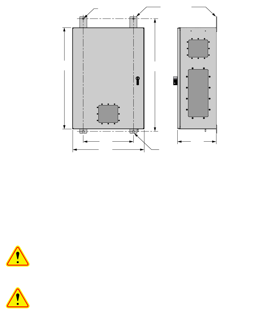
Mounting
Figure 2 shows the mounting hole dimensions and
layout for the cabinet. Mount the cabinet using 3/8”
(10 MM) diameter steel bolts (not supplied). We
recommend flat washers on both ends and a lock
washer under the nut. Nut and bolt mounting is
preferred to the use of lag bolts. Use backer blocks
where necessary to spread the force over a larger
area. In areas of known seismic activity, additional
devices such as tether lines may be necessary.
Because Bird Technologies cannot anticipate all of
the possible mounting locations and the structure
types where these devices will be located, we rec-
ommend consulting local building inspectors, engi-
neering consultants or architects for advice on how
to properly mount objects of this type, size and
weight in your particular situation. It is the custom-
ers responsibility to make sure that these devices
are mounted safely and in compliance with building
codes.
Connections
All RF cabling connections to the booster should
be made and checked for correctness prior to pow-
ering up the system. N(f) bulkhead connectors are
available at the top of the booster enclosure box for
connection to the system antennas. Make sure the
Intermediate
Frequency
Signal
Processing
1st Mixer 2nd Mixer
RF OutRF In
Local
Oscillator
Figure 1: The down converter / up converter process.
TX RX Systems Inc. Manual 7-9485-1.9.1 10/26/17 Page 10
correct branch of the antenna system is connected
to its corresponding uplink/downlink connector or
the system will not work properly. Using high qual-
ity connectors with gold center pins is advised.
Flexible jumper cables made of high quality coax
are also acceptable for connecting to rigid cable
sections.
Caution: The ERP (effective radi-
ated power) from the booster sys-
tem must not exceed +37 dBm (5
Watts) in order to remain compliant
with FCC regulations.
Caution: The maximum continu-
ous input power level for this
booster is -20 dBm. Stronger input
signals will cause the unit to exceed
it’s IM specifications. Static input
signals greater than -10 dBm may
damage the unit.
Models of the booster are available for either AC or
DC operation. Based on the model number (see
table 1) the booster is designed to be plugged into
either a single phase AC line (110 VAC at 50/60
Hz) or a - 48 Volt DC source. A connector is avail-
able at the top of the equipment box for connecting
the AC or DC source voltage.
Antenna Isolation
Antenna isolation between uplink and downlink
should be measured before connecting the signal
booster to the antenna system. This step is neces-
sary to insure that no conditions exist that could
possibly damage the signal booster and should not
be skipped for even the most thoroughly designed
system.
Just like the feedback squeal that can occur when
the microphone and speaker get too close together
in a public address system, a signal booster can
start to self oscillate. This can occur when the iso-
lation between the Uplink and Downlink antennas
does not exceed the signal boosters gain by at
least 15 dB. Oscillation will reduce the effective-
ness of the system and may possibly damage
amplifier stages. Isolation values are relatively
easy to measure with a spectrum analyzer and sig-
nal generator.
0.44 Dia
(2 places)
0.44 wide slot (2 places)
33.2430.00
14.00 10.8
20.00
Mounting Tabs
(4 Places)
Figure 2: Cabinet mounting hole layout.
TX RX Systems Inc. Manual 7-9485-1.9.1 10/26/17 Page 11
REQUIRED EQUIPMENT
The following equipment is required in order to per-
form the antenna isolation measurements.
1) Signal generator for the frequencies of interest
capable of a 0 dBm output level. Modulation is
not necessary.
2) Bird Technologies “Signal Hawk” spectrum ana-
lyzer which will cover the frequencies of interest
and is capable of observing signal levels down
to -100 dBm or better.
3) Double shielded coaxial test cables made from
RG142, RG55 or RG223 coaxial cable.
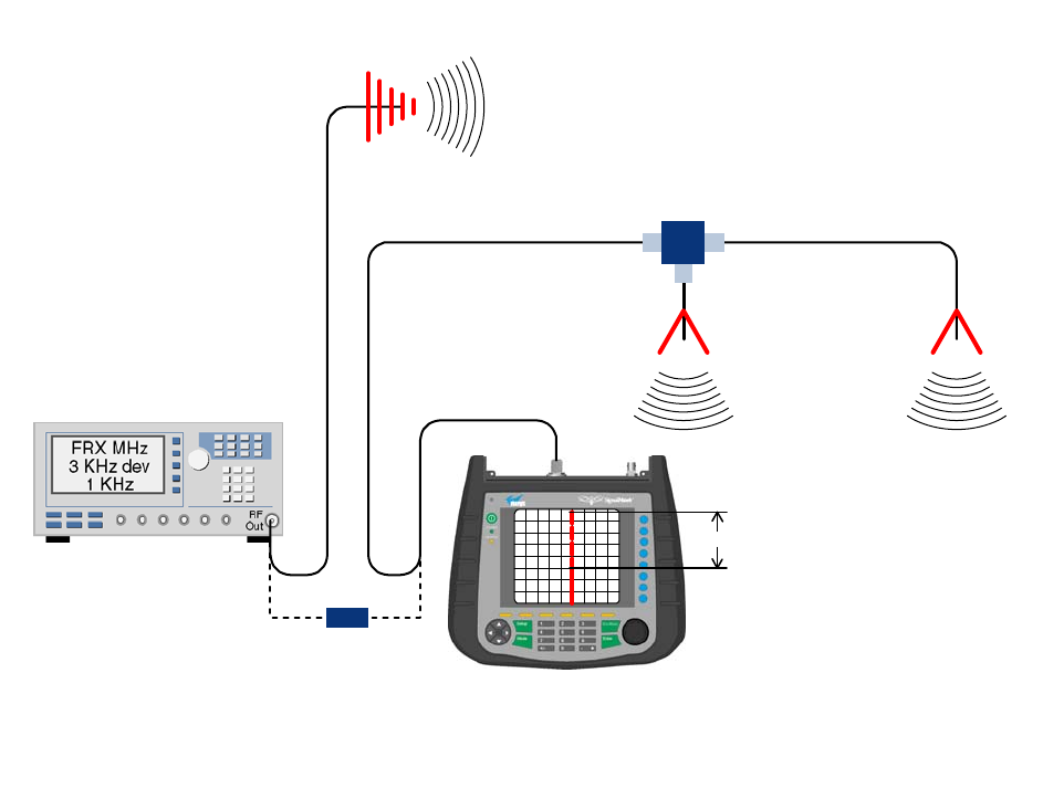
MEASUREMENT PROCEDURE
To measure the antenna isolation perform the fol-
lowing in a step-by-step fashion.
1) Set the signal generator for a 0 dBm output level
at the center frequency of the boosters pass-
band.
2) Set the spectrum analyzer for the same center
frequency and a sweep width equal to or just
slightly greater than the passband chosen ear-
lier in step 1.
3) Temporarily connect the test leads of the signal
generator and spectrum analyzer together
using a female barrel connector, see Figure 3.
Observe the signal on the analyzer and adjust
the input attenuator of the spectrum analyzer for
a signal level that just reaches the 0 dBm level
at the top of the graticule.
4) Referring to figure 3, connect the generator test
lead to one side of the antenna system and the
spectrum analyzer to the other then observe the
signal level. The difference between the
observed level and 0 dBm is the isolation
between the sections. If the signal is too weak
to observe, the spectrum analyzer’s bandwidth
may have to be narrowed and it’s input attenua-
tion reduced. The isolation value measured
Signal Generator
External
Antenna
(YAGI)
Spectrum Analyzer
Isolation (dB)
Zero Loss
Reference
Internal
Signal Distribution
System
(Omni-directional
Antennas)
Figure 3: Typical test equipment interconnection for measuring antenna isolation.
TX RX Systems Inc. Manual 7-9485-1.9.1 10/26/17 Page 12
should exceed the signal booster’s gain figure
by at least 15 dB.
5) Repeat step 4 again with the signal generator
set at the passband edges in order to see if the
isolation is remaining relatively constant over
the complete width of the passband.
6) Repeat the isolation measurements if neces-
sary at other system passbands to determine
the overall minimum isolation value for the sys-
tem. Physical modification of the antenna sys-
tem maybe required in order to reach an
acceptable minimum value.
RF EXPOSURE
To comply with FCC RF exposure compliance
requirements, a separation distance of at least 69
cm must be maintained between the antennas of
this device and all persons. To comply with IC RF
exposure compliance requirements, a separation
distance of at least 100 cm must be maintained
between the antennas of this device and all per-
sons. This device must not be co-located or operat-
ing in conjunction with any other antenna or
transmitter.
EXPOSITION RF
Pour conformer aux exigences d'exposition de
FCC RF, une distance de séparation d'au moins 69
cm doit être maintenue entre les antennes de cet
appareil et toutes les personnes. Pour conformer
aux exigences d'exposition de IC RF, une distance
de séparation d'au moins 100 cm doit être main-
tenue entre les antennes de cet appareil et toutes
les personnes. Cet appareil ne doit pas être co-
localisé ou exploités en conjonction avec toute
autre antenne ou transmetteur.
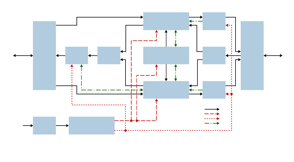
SIGNAL FLOW BLOCK DIAGRAM
Figure 4 is the signal flow block diagram of the
standard channelized signal booster model 6138X.
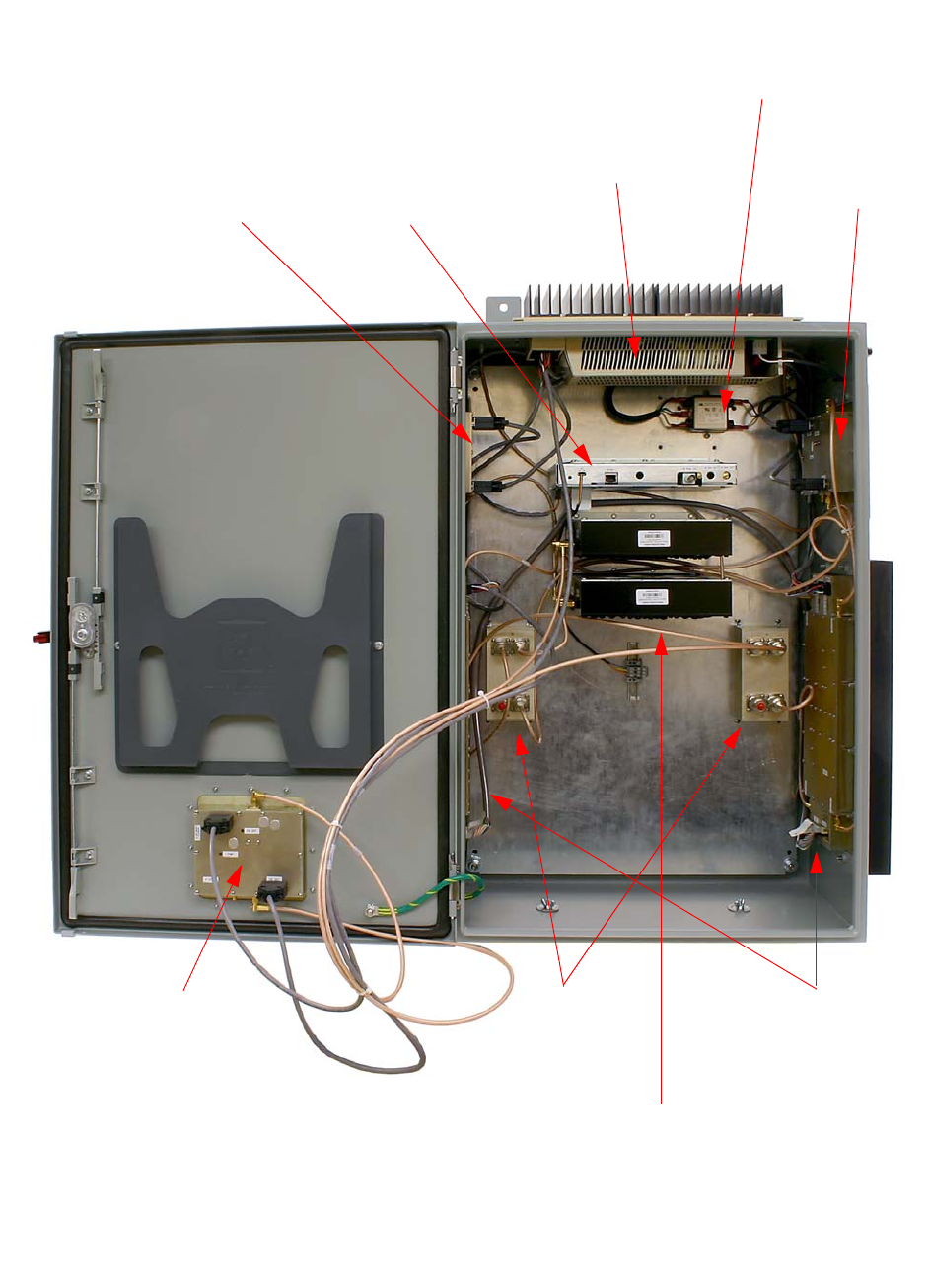
Figure 5 shows the front view of the booster cabi-
net. The channel modules are bi-directional with
each module containing one downlink branch and
one uplink branch. The branches are functionally
identical because the same circuit board designs
are used in each branch. The uplink and downlink
branches may be programmed to any frequency in
the appropriate band.
Uplink and Downlink Input Signals
Uplink input signals (794 - 806 and 806 - 824) are
picked up by the DAS antenna and applied to the
triplexer. The uplink input signals pass through the
triplexer and are fed into a directional coupler
Channel Module
3-23350-1
Channel Module
3-23368-1
Control Module
3-23360-1
Hybrid
Coupler
3-5688
Hybrid
Coupler
3-5688
Power
Amp
3-23665
Power
Amp
3-23665
Power
Amp
3-23665
Line
Filter
8-23887
Triplexer
8-23088
Triplexer
8-23088
Donor
Antenna
AC
In
DAS
Antenna
Power Supply Module
+28VDC & +6VDC Output
3-23912
RF Connections
+6V Power
+28V Power
Communications
Figure 4: Signal flow block diagram of the channelized signal booster.
Dual band high power model shown as an example.
TX RX Systems Inc. Manual 7-9485-1.9.1 10/26/17 Page 13
Figure 5: Front view of the booster.
Power
Amplifier
Channel
Module
Triplexers
Power
Amplifier
Power
Amplifier
Control
Board
Line
Filter
Power
Supply
Directional
Coupler

TX RX Systems Inc. Manual 7-9485-1.9.1 10/26/17 Page 14
where they are distributed to the uplink input port of
both the 700 and 800 MHz channel modules.
Downlink input signals (764 - 776 and 851 - 869)
are picked up by the Donor antenna and applied to
the triplexer. The downlink input signals pass
through the triplexer and exit at either the 700 or
800 MHz output port. The 700 and 800 MHz down-
link inputs signals are then applied to the downlink
inputs of the respective 700 and 800 MHz channel
modules.
Channel Module
The uplink input signals and the downlink input sig-
nals are applied to a down-converter board when
they enter the channel module. Within the channel
module input signals are down converted, digitized,
and DSP filtering is performed. There are two
Location Label Possible
States Causes Action
to take
Bottom of channel module DL/UL PWR Green solid FPGA successfully loaded None
Bottom of channel module DL/UL PWR Off Issue with board Return to factory
Bottom of channel module DL/UL COM Red flashes Exchanging data with con-
trol board None
Bottom of channel module DL/UL COM Red solid Exchanging data with con-
trol board None
Bottom of channel module DL/UL COM Off No data exchanging None
Bottom of channel module DL/UL COM
Always Off and it
is expected to
flash
No data exchanging Check cabling; return con-
trol board to factory
Bottom of channel module DL/UL DAC Red solid DAC overflow Lower output power setting
Bottom of channel module DL/UL DAC Off DAC normal operation None
Bottom of channel module DL/UL ADC Red solid ADC overflow Increase down converter
attenuation
Bottom of channel module DL/UL ADC Off ADC normal operation None
Control board Ctrl LED Off no power, no bootloader,
no program Return to factory
Control board Ctrl LED Orange bootloader installed, no
program
return to factory or perform
field update
Control board Ctrl LED Red Control board detected a
fault
Address fault condition.
Contact factory
Control board Ctrl LED Green solid Control board normal oper-
ation None
Power Amplifier PWR Green solid 6 VDC supply to Amplifier
is OK None
Power Amplifier PWR Off No supply voltage check power supply and
cabling
Power Amplifier PA OFF Off Power Amp normal opera-
tion None
Power Amplifier PA OFF Red solid Over current, over temp Amp shut down, contact
factory
Table 3: Subassembly LED descriptions.
TX RX Systems Inc. Manual 7-9485-1.9.1 10/26/17 Page 15
styles of Channel modules available, a 14 channel
version and a 30 channel version. After DSP filter-
ing the analog signal is recreated and up converted
with an up-converter board to the original fre-
quency before being output from the channel mod-
ule at the downlink and uplink output ports.
Up converter boards are available in two different
styles including low level and high level. If the sig-
nal booster is a high-power model then a low level
up converter board is used in the channel module.
If the booster is a low power model then high level
up converter boards are used. Signal booster mod-
els that have the fiber-optic option installed in them
have enhanced down-converter boards that are
capable of dealing with the low level signals from
the optical conversion.
Uplink and Downlink Output Signals
Uplink and Downlink output signals leave the chan-
nel module at the UL OUT and DL OUT connectors
respectively. The 700 and 800 MHz uplink output
signals are combined with a directional coupler
then passed on to a power amplifier stage. The
output of the power amplifier is passed through a
triplexer then radiated from the donor antenna.
Note: When the booster is operated at the maxi-
mum uplink output power level the gain of the
donor antenna should be limited to +10 dBi.
Downlink output signals leave the channel module
and are applied to a power amplifier stage. The
output of the power amplifier is passed through a
triplexer then radiated from the DAS antenna. Note:
When the booster is operated at the maximum
downlink output power level the gain of the DAS
antenna should be limited to -4 dBi.
OPERATION
Power is applied to the channelized booster by
plugging in the AC or DC power cord (depending
on how the system was configured for input
power).
Subassembly LED’s
LED’s are located on several of the subassemblies
within the Booster cabinet. The function of each of
these indicator LED’s are listed in Table 3.
COMMUNICATING WITH THE BOOSTER
The booster provides Ethernet connectivity that
allows access to a web-based user interface for
communicating with the control board, program-
ming the individual channels, checking system sta-
tus, etc. Communications will require connecting
your laptop computer to the Enet connector on the
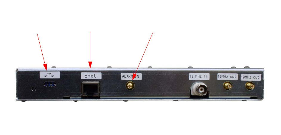
control board. Figure 6 shows the connector. A
standard Ethernet crossover cable is used to make
the connection between your laptop computer and
the booster cabinet. Refer to Appendix A at the
back of this manual for detailed instructions on how
to properly connect your laptop computer to the
Enet port of the booster.
System Summary Submenu
Once your laptop computer is properly connected
to the signal booster the web-based user interface
screen will appear as shown in Figure 7. This is
the System Summary page which shows the IP
and MAC address of the control module. On the
Figure 6: Enet connector on the control board.
Summed Alarm
Green = Normal
Red = Alarm
Enet
Connector
Fiber Optic Module
connects here
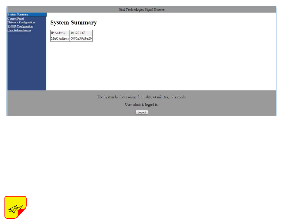
TX RX Systems Inc. Manual 7-9485-1.9.1 10/26/17 Page 16
left-hand side of the page are a list of the major
submenus available to the user including System
Summary, Control Panel (see note below), Network
Configuration, SNMP Configuration, and User
Administration.
When the web-based user interface
first comes up, the Control Panel sub-
menu choice will not be displayed.
The user needs to go to the User
Administration submenu and type in
the default user name (admin) and
default user password (admin). After
the login function is performed the
Control Panel submenu choice will
appear.
Place your cursor over a particular submenu head-
ing and left click to make a selection. Each major
submenu page contains a group of related func-
tions. Without entering your user password the
user will only be allowed to view the pages how-
ever and will not be able to make changes without
entering a password. After entering a valid pass-
word via the Admin submenu the pages will switch
from read only to fully interactive and the user can
begin making selections and changes if desired.
Control Panel Submenu
The Control Panel submenu gives the user the abil-
ity to interface with and adjust the RF parameters
of the booster. Four tabs are available on the Con-
trol Panel Page including FILTERS, FILTER
DETAIL, LINK, and SYSTEM. When selected each
tab presents a new screen and each screen con-
tains groups of related functions. Selection is made
by placing your cursor over the tab and performing
a left click.
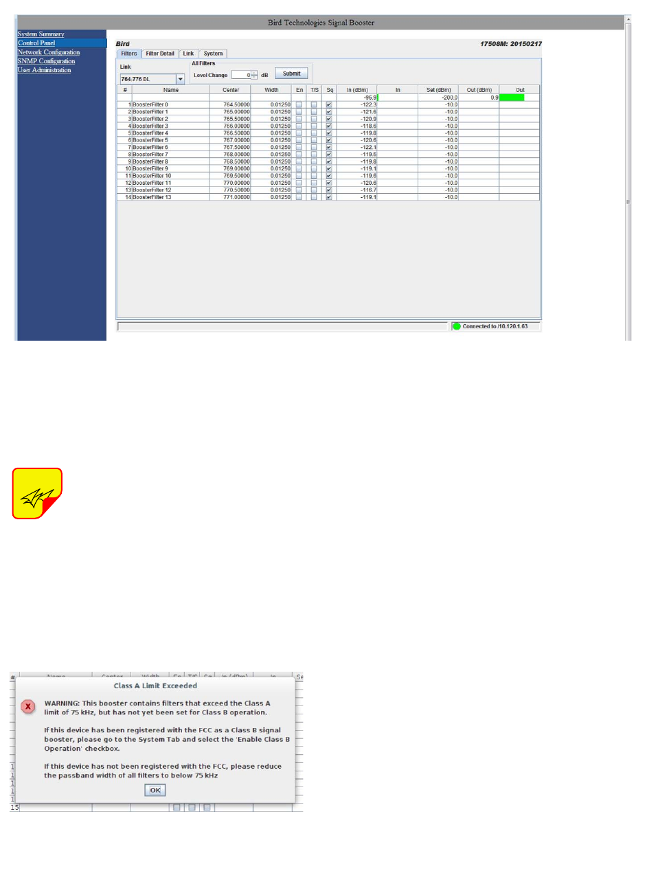
FILTERS TAB
The Filters page gives an overview of all the filters
associated with each branch in the booster system.
Refer to Figure 8. The link drop-down box allows
you to select which branch you want to overview.
Press the down arrow button and highlight the
desired branch. Each filter is accorded one row in
the display. The first row of displayed data is used
to provide a summation of the input and output
power for the branch. The parameters displayed for
each filter include; Center Frequency, Bandwidth,
Channel Enabled, Test Signal, Squelch, the Input
Signal Level as both a numeric value and a bar
graph, Maximum Allowed Output Level, and Output
Signal Level as both a numeric value and a bar
graph. Changes to the filters are made from the Fil-
ter Detail page.
The enable, test signal, and squelch boxes are
interactive on this display. Place a check mark in
the box when you want the function selected. Place
your mouse cursor over the box and left click. A
check mark placed in the box for enable, test sig-
nal, or squelch indicates that function is turned on
while no check mark indicates the function is
turned off. The All Filters area at the top of the
page allows the user to adjust the Maximum Out-
put Level of all the filters in a branch simulta-
NOTE
Figure 7: System Summary Submenu.
TX RX Systems Inc. Manual 7-9485-1.9.1 10/26/17 Page 17
neously. Use the up or down arrow to set the level
change amount then press the submit button.
On start-up, the booster validates the
widths of programmed filters. If any
are configured wider than 75 KHz and
the booster is set to Class A mode an
error message as shown in Figure 9
will appear. The offending filter or fil-
ters must be corrected or the booster must be
switched to Class B mode. Refer to the System tab
discussion later in this manual for instructions on
switching from Class A to Class B mode of opera-
tion.
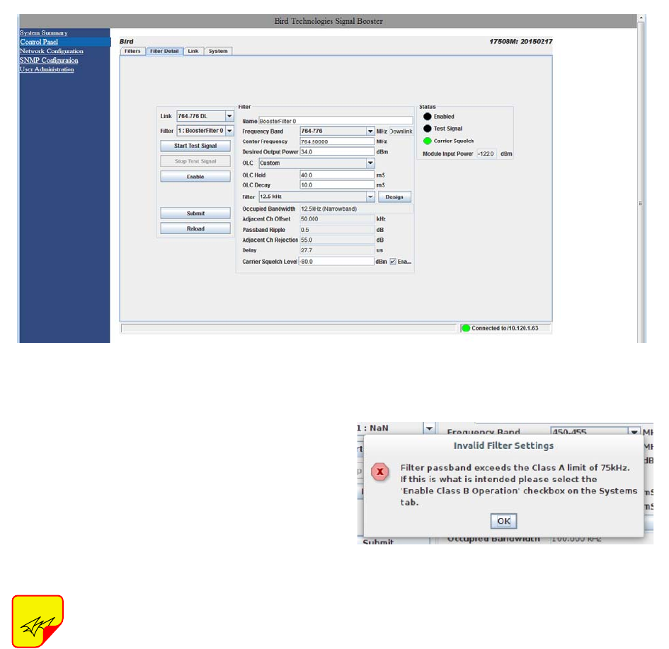
FILTER DETAIL TAB
The Filter Detail page is divided into three func-
tional areas. The first area includes a pair of drop
down boxes along with a row of command buttons
running down the left side of the screen. The sec-
ond area is a filter details area in the middle of the
screen. The third is a status area on the right side
of the screen as shown in Figure 10. Once you
have interactive access to the Filter Detail page
you can begin programming the individual filters
that you want the booster to pass in the uplink and
downlink direction.
The Filter Detail page is designed to interact with
one filter at a time. To program individual filters you
must select the branch and the filter of interest
using the Link and Filter boxes on the left side of
the screen. Once the filter has been selected for
interaction a label can be assigned to the filter by
typing into the name box. Three groups of charac-
teristics need to be defined including frequency
band, OLC, and filter specifics. Frequency band is
selected from a drop down list. Center Frequency
and Desired Output Power level must be entered
by the user by clicking in the box and typing in the
desired value. Likewise OLC style is determined
with a drop down box. The two choices are Custom
and APCO 25 Phase 2. OLC Hold time and OLC
Decay time must be entered by the user.
NOTE
Figure 8: The Filter Summary Tab.
Figure 9: Class A limit exceeded warning message.
TX RX Systems Inc. Manual 7-9485-1.9.1 10/26/17 Page 18
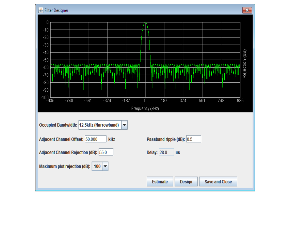
Filter specifics are selected from a drop down list
that includes Custom, 12.5 KHz, 25 KHz, 12.5 KHz
Low Delay, and XML File. Four parameters are
customer adjustable including Occupied Band-
width, Adjacent Channel Offset, Passband Ripple,
and Adjacent Channel Rejection. Delay time is cal-
culated by the software. The four adjustable
parameters are setup using the Design Filter tool,
see the following section of this manual for details.
If a filter passband is selected that
exceeds the Class A limit of 75 KHz
and Class B operation is not selected
(see discussion in System tab section
of this manual) then a warning mes-
sage will appear as shown in Figure
11. You must set the booster to the
Class B mode of operation if you have
any filter with a passband greater than
75 KHz.
Design Button
When the Design Filter button is pressed a custom
design template will be displayed as shown in Fig-
ure 12. Boxes for the four required filter parameters
mentioned earlier are shown along with a graphical
representation of the filter’s response curve. Enter
into the four boxes the parameters you want. Click
on the Estimate button at the bottom of the screen
and the software will calculate the Delay time for
you. Press the Design button to design the filter.
The rejection scale of the display can be changed
by making a selection from the “maximum plot
rejection” drop down list. Choices include -10, -50,
and -100 dB scale. When the display is to your sat-
isfaction and does not violate any parameter
ranges press the Save and Close button to exit
back to the filter detail screen then load the design
into the selected filter by pressing the Submit but-
ton on the filter detail page.
Status Area
The status area of the Filter Detail page uses sta-
tus indicators to let the user know whether the
channel is enabled, if the test signal is on, and if
the carrier squelch is on. When the status indicator
NOTE
Figure 10: Filter Detail Tab.
Figure 11: Invalid filter settings warning message.
TX RX Systems Inc. Manual 7-9485-1.9.1 10/26/17 Page 19
is illuminated the feature is on and when it is dark
the feature is off. The Carrier Squelch status indi-
cator will be green if the channel is squelched. The
Carrier Squelch status indicator will stay dark if
there is no squelching even if the Carrier Squelch
radio button is set to enabled. A test signal can be
generated for any channel within the system or
every channel simultaneously.
The output power box displays the output power for
the channel module. This value should be close but
not necessarily exactly the same as the “Desired
Output Level” discussed earlier. The box showing
output power is only displayed if the filter is giving
an output power. If the filter is not enabled or there
is no signal present then there would be no value
to display.
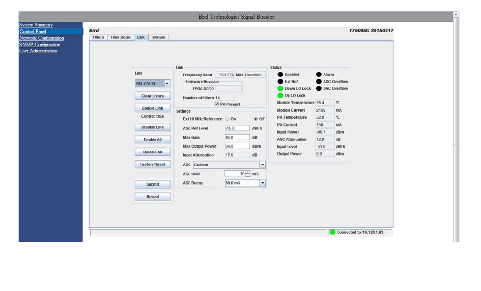
LINK TAB
The link page is divided into three functional areas
including a row of command buttons running down
the left side of the screen, a link and a settings
area in the middle of the screen, and finally a sta-
tus area on the right side of the screen as shown in
Figure 13. The link page is designed to interact
with one branch of a module at a time. The branch
that is selected for interaction is determined by the
Link box on the upper left of the screen. To change
the branch that you are going to interact with click
on the arrow to display the full drop down box.
Scroll down the list until the desired branch is high-
lighted and click on it. The data displayed in the link
area of the display screen will now be for the
selected branch.
Command Buttons
Clicking on a command button (located on the
extreme left-hand side of the page) performs the
associated task immediately. The Submit and
Reload buttons in the bottom left corner allow any
changes you make to the display/interface boxes to
be downloaded to the booster. The Submit and
Reload buttons act like a trigger sending any
changes you made in the interface boxes to the
Figure 12: The design filter interactive display screen.
TX RX Systems Inc. Manual 7-9485-1.9.1 10/26/17 Page 20
channel module as well as updating any displayed
data from the module, but only after the button is
pressed. Individual branches or all branches can
be enabled or disabled using the enable/disable
buttons. After an alarm condition is corrected the
alarm can be cleared by selecting the clear errors
button. Selecting the factory reset button will return
the system to the factory default settings.
Link and Settings Area
The link portion of the area displays status informa-
tion for the branch. The Settings area is a user
interactive area where the field engineer can pro-
gram the operating characteristics of the selected
branch. Each parameter in the settings area can be
changed by clicking in the box and typing in the
new values or by pointing at an arrow to display a
drop down box. Most of the adjustable parameters
have adjustment limitations as applicable.
The parameters include turning on/off the use of an
external 10 MHz reference signal when an external
reference is available. If an external reference is
not available then leave this feature off and the sys-
tem will operate from the internal 10 MHz signal.
The AGC Reference Level should be set to the cal-
ibration value which is -15 dBFS. The ADC refer-
ence level can be adjusted when excessively
strong input signals are present. The Maximum
Output Power is the desired output power level
from the booster for the selected branch. The Max
Gain allows the user to determine the maximum
operating gain of the booster. This can be adjusted
based on your antenna isolation.
The changes you make in the Settings area are
only applicable to the selected branch. After you
have made changes to the various parameters
press the Submit command interface button (lower
left corner of the screen) in order to copy the
changes into the channel module itself.
Status Area
The status area of the link page lets the user know
the status of the channel module and power ampli-
fier if a power amplifier is used in the system
design. The status for seven parameters are con-
veyed by the status indicator next to the parameter
name. When the status indicator is green it indi-
cates that the parameter is on and when it is black
it indicates the parameter is off. In the case of the
Alarm (Summed Alarm), ADC Overflow, and DAC
Overflow, the status indicator will turn red during a
fault condition.
Figure 13: The Link Tab.
TX RX Systems Inc. Manual 7-9485-1.9.1 10/26/17 Page 21
When the Summed Alarm indicator is
red, if the cursor is placed over the
indicator, a message tab will appear
briefly describing the reason for the
alarm condition.
Seven additional parameters are displayed with
numerical values. The first group of parameters
include; Enabled which indicates whether the
branch is on or off, Ext Ref which indicates whether
the system is running on an external or internal 10
MHz clock signal, and Down and Up LO Lock
which indicate if the down converter and up con-
verter local oscillators are synchronized to their
respective RF signals. The second group of param-
eters using a status indicator will be black under
normal conditions and will turn red to indicate a
fault. The Alarm indicator is a summed alarm and
will activate when either the module or power
amplifier temperature/current exceeds their nor-
mal range. Also, the Form-C contacts inside the
cabinet will change states. ADC or DAC Overflow
indicator shows that the input power to the branch
is too high.
If a fault occurs, press the clear errors
button on the left side of the page. If
the error reappears right away then
trouble shooting will need to take
place.
The first four numerical parameters are real-time
indications of the module and power amplifier tem-
perature/current values. AGC Attenuation updates
in real-time and provides an indication of what the
AGC is doing. Input Power is a summation of all the
input signals to the branch. Output power also
updates in real-time and indicates the composite
power output for the branch.
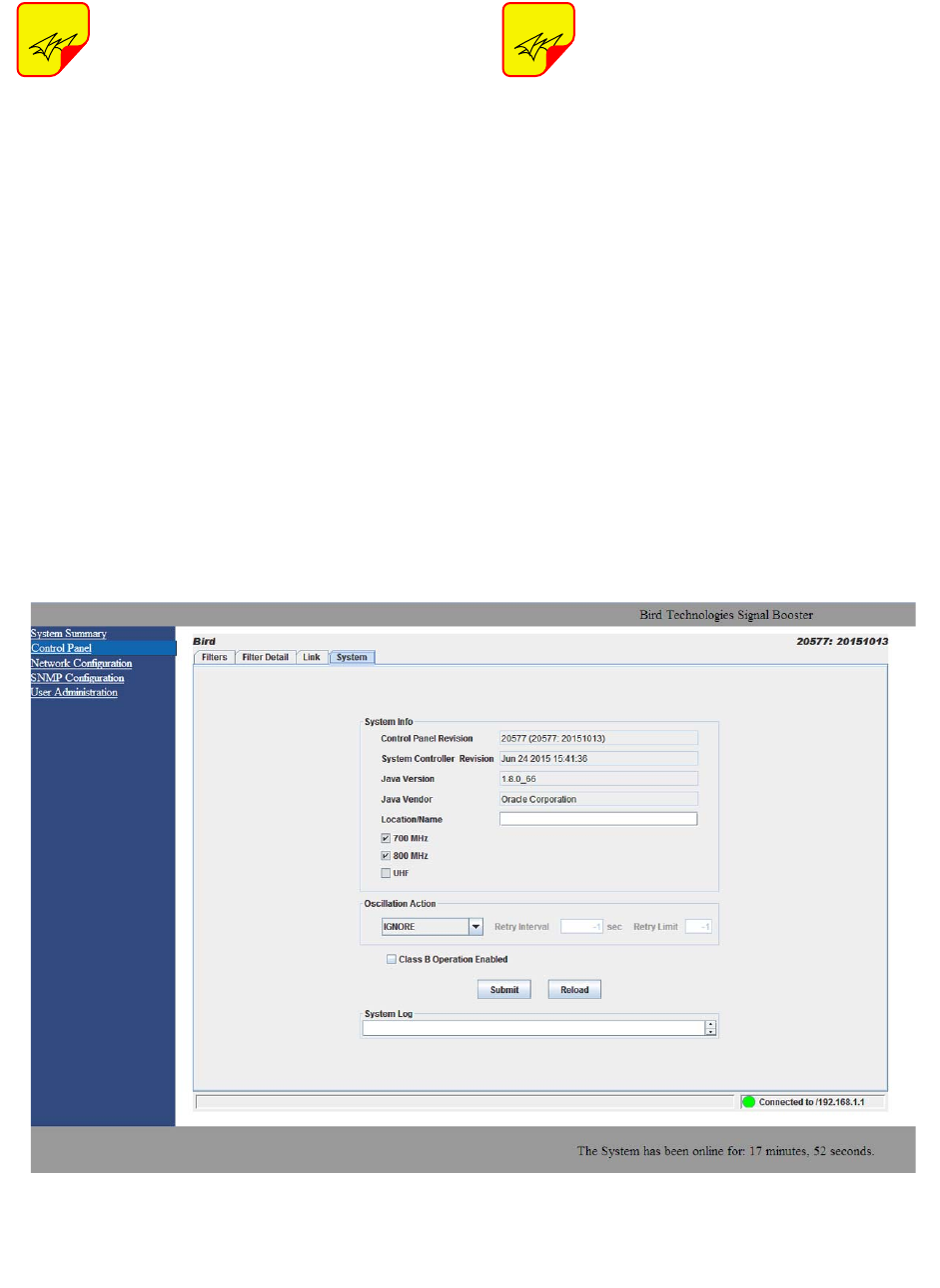
SYSTEM TAB
The system tab lists the control board software ver-
sions. A customer-designated location name can
be recorded and is useful in situations where multi-
ple boosters are used in the overall system design.
There is also a system logbook available on the
bottom of this page for use by field engineers when
working on the system. Refer to Figure 14.
NOTE
NOTE
Figure 14: The System Tab.
TX RX Systems Inc. Manual 7-9485-1.9.1 10/26/17 Page 22
Oscillation Detection
This feature shuts off the output signals from the
booster for both the uplink and downlink whenever
an oscillation condition is detected. Oscillation
detection occurs whenever port to port isolation
falls down to 25 dB or less. For normal operation
the port to port isolation needs to be at least 10 dB
greater than the gain of the booster. There are four
modes of operation for the Oscillation Detection
feature including Ignore, Alarm, Shutdown, and
Shutdown/Retry.
In the Ignore mode the booster will ignore oscilla-
tion events. In the Alarm mode the booster will gen-
erate an alarm notification by illuminating (RED)
the alarm button on the Link Tab and illuminating
(RED) an LED indicator on the control module. The
Shutdown mode is the same as Alarm mode
except the booster shuts off the output signals in
both the uplink and downlink direction. The shut-
down continues until the filters are re-enabled and
the alarm is reset. The Shutdown/Retry mode is
the same as the Shutdown mode except the
booster will retry operation the number of times
specified by the user. This is called the retry limit
which is entered into the associated box on the
System Page. How long the booster waits between
each retry attempt is determined by the retry inter-
val. After the retry limit is reached, if the booster is
still experiencing an oscillation condition, the
booster will enter the regular shutdown mode. The
Shutdown/ Retry mode is useful in situations where
brief transient overdrive signals are occurring.
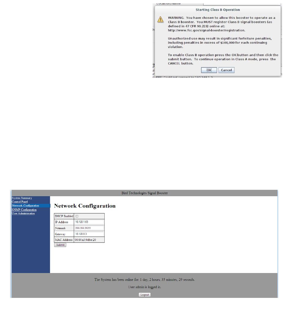
Class B Enable
In order to operate the booster with a filter pass-
band greater than 75 KHz the booster MUST be
configured as a Class B booster and the customer
must register the booster online with the FCC.
Class B operation is enabled by checking the box
labeled “Enable Class B Operation”. When the box
is checked a warning message will be displayed as
shown in Figure 15 reminding the user to register
the booster with the FCC.
Network Configuration Submenu
Values for IP Address, Netmask, the Gateway and
MAC Address are displayed on the network config-
uration page. Refer to Figure 16.
The network configuration page allows the user to
enable or disable DCHP. The Dynamic Host Con-
trol Protocol (DHCP) is a standardized networking
protocol used on IP networks for dynamically dis-
Figure 16: Network Configuration Submenu.
Figure 15: Starting Class B operation message.
TX RX Systems Inc. Manual 7-9485-1.9.1 10/26/17 Page 23
tributing network configuration parameters, such as
IP addresses for interfaces and services. With
DHCP, computers request IP addresses and net-
working parameters automatically from a DHCP
server, reducing the need for a network administra-
tor or a user to configure these settings manually.
The DCHP (Dynamic Host Configuration Protocol)
is either active or inactive. When DCHP is active
the values for IP address, netmask, and gateway
are set to zero. When the DCHP is inactive (default
setting from the factory) the IP address, netmask,
and gateway values can be modified by the user by
typing the desired values into the associated box
and pressing the submit button. The customer
should consult with their IT department to deter-
mine whether DCHP should be active or inactive.
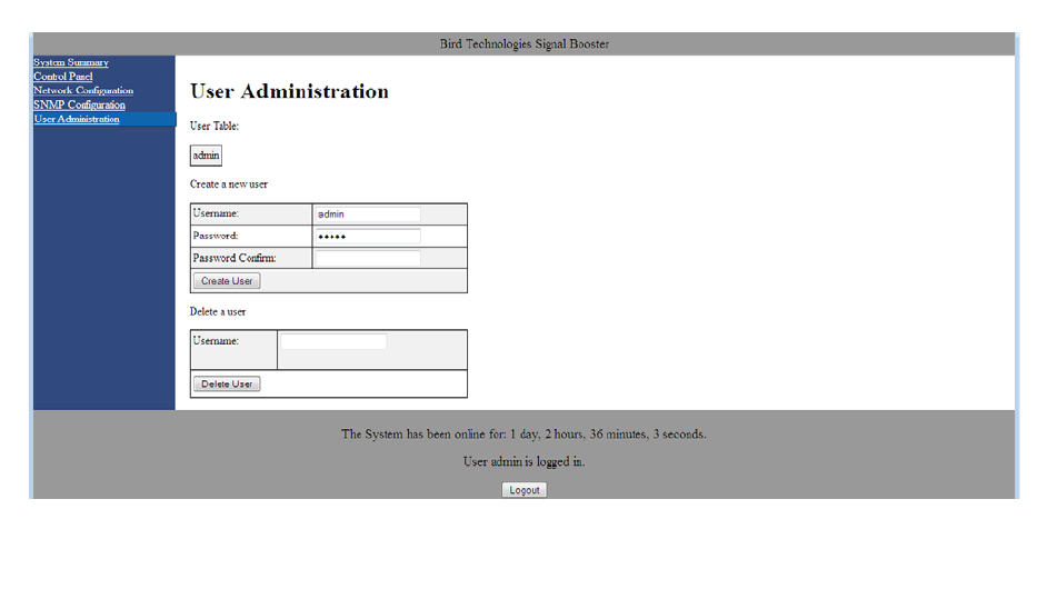
User Administration Submenu
The User Administration submenu allows pass-
word protected access to the booster. The boxes
on this page are interactive. To make changes click
inside the box and a cursor will appear. Refer to
Figure 17. The user is queried for a User Name
and User Password. The default user name is
“admin” and the default password is “admin”. It is
recommended that once the booster system is
installed approved users with unique passwords
are loaded into the system and the default admin
user/password is deleted.
Once the correct user name and password are
entered then a menu box for creating a new user
will be presented. To create a new user enter the
new user name and associated password. Confirm
the new password by entering it again and then
press the Create User button. Make sure you write
down the new user name and password for safe
keeping. A menu box for deleting a user is also pre-
sented. To delete a user enter their user name in
the box and click on the Delete User button.
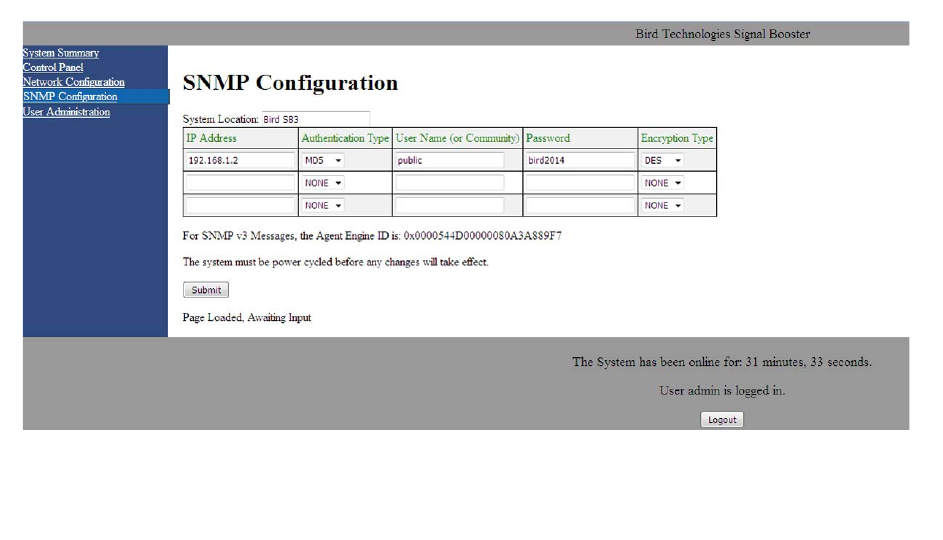
SNMP Configuration Submenu
Simple Network Management Protocol (SNMP) is
an Internet-standard protocol for managing devices
on IP networks. The SNMP feature is designed to
provide reliable internet notification of an alarm
occurrence or a change in operational status in the
booster. In order to configure the booster to send
SNMP messages (called traps) to a destination
device, such as your computer, the following values
need to be entered into the booster; System loca-
tion, the IP address of the destination computer,
Authentication type, User name, Password, and
Encryption type, and the Encryption passphrase.
Figure 18 shows the SNMP Configuration display.
The System location is a user defined string which
will be returned with every trap that is generated
and can assist the user in identifying which unit is
sending the trap message. The three destination IP
addresses that are entered into the table should be
Figure 17: User Administration Submenu.
TX RX Systems Inc. Manual 7-9485-1.9.1 10/26/17 Page 24
the IP addresses of the computers that you want
the traps to be sent to. These destination comput-
ers must have SNMP manager software installed
and running in order to receive the messages.
SNMP manager software installation into the desti-
nation computers is the customers responsibility.
Consult with your IT specialist for assistance.
Authentication type is used to verify that the person
receiving the trap is the person the trap is intended
for. Authentication type choices are NONE, MD5,
or SHA, with SHA being the strongest encryption
type. When using authentication and/or encryption
the User Name is the name of the person to
receive the trap. If not, this is the community name
of the trap receiver. The Password is a string used
to encrypt and authenticate the user. It is only used
when authentication and/or encryption types are
enabled. The Encryption type is used to protect the
contents of the message from unauthorized receiv-
ers. Encryption type choices are NONE, DES, or
AES, with AES being the strongest supported
encryption type.
The Agent ID is a value that uniquely identifies the
agent sending the traps. The agent is software
which runs on the device being monitored and in
this case is the signal booster. The SNMP man-
ager software receives the traps and can be run on
your computer or another server on your network.
For traps that use encryption and/or authentication
the manager needs to be configured to receive
traps from the specified agent ID. This number is
shown on the SNMP submenu page underneath
the table, refer to figure 18.
Whenever values in the SNMP Configuration
screen are changed you must click on the submit
button to save the changes.
INITIAL SNMP SETUP
When the booster is installed the SNMP feature
should be setup for proper communications. There
are several steps required for proper setup of the
SNMP feature as discussed below.
1) Connect a laptop directly to the booster. Refer
to Appendix A for detailed instructions on how
to make a direct connection. The booster is
shipped from the factory setup for static IP
addressing and with a default IP address of
“192.168.1.1”. The factory default subnet mask
is “255.255.255.0”. Change the factory default
IP address of the booster to one provided by
your IT department.
2) Use the Network Configuration to setup the
DHCP as either active or inactive. When DHCP
is inactive the deck will be using a static IP and
the user must enter values for IP address, net-
mask, and gateway. Make sure you consult with
Figure 18: SNMP Configuration Submenu.
TX RX Systems Inc. Manual 7-9485-1.9.1 10/26/17 Page 25
your IT department regarding setting DCHP
active or inactive.
3) Use the SNMP Configuration submenu page to
enter up to three destination device addresses.
These are addresses where the SNMP feature
will send trap messages whenever a qualifying
event takes place. Qualifying events include the
following;
A) Down Converter LO Lock Fail
B) UP Converter LO Lock Fail
C) ADC Overflow
D) DAC Overflow
E) General Alarm - over current, over temp,
and oscillation.
4) Setup the SNMP format using the SNMP Con-
figuration submenu page. Items that need to be
configured include Authentication Type, User
Name, Password, and Encryption Type. Consult
with your IT specialist for assistance.
5) Load the SNMP manager software into the des-
tination computer and configure the manager so
that it will be able to receive the SNMP traps.
6) Download MIB files from the Bird Technologies
website (www.birdrf.com) and load the MIB files
into your SNMP manager software. The MIB
files allow the SNMP manager software to sort
out the trap messages into an understandable
message format.
The signal booster supports several SNMP Config-
uration validation checks which help ensure the
configuration is setup in a logical format. The vali-
dation checks include;
A) If encryption is enabled but authentication is not
enabled a popup window will appear stating that
you must enable authentication when encryp-
tion is enabled.
B) If Authentication and/or Encryption is enabled
and a password is entered which is < 8 charac-
ters long an error message will be displayed.
C) If an IP address is entered but a User Name is
not entered a popup warning will appear but the
changes will be submitted.
D) If a User name is entered but an IP address is
not entered a popup warning will appear but the
changes will be submitted.
SNMP MANAGER EXAMPLE
SNMP manager software is designed to provide a
GUI style interface for the user so that traps sent
from the booster can be received and displayed for
viewing. The SNMP manager software chosen and
used by the customer is up to the customers dis-
cretion and as such may not exactly match the
example shown in this discussion. SNMP manager
software packages will need to be properly config-
ured in order to successfully receive messages
from the booster. Refer to the SNMP configuration
setup discussed earlier in this manual and ask your
IT specialists for assistance.
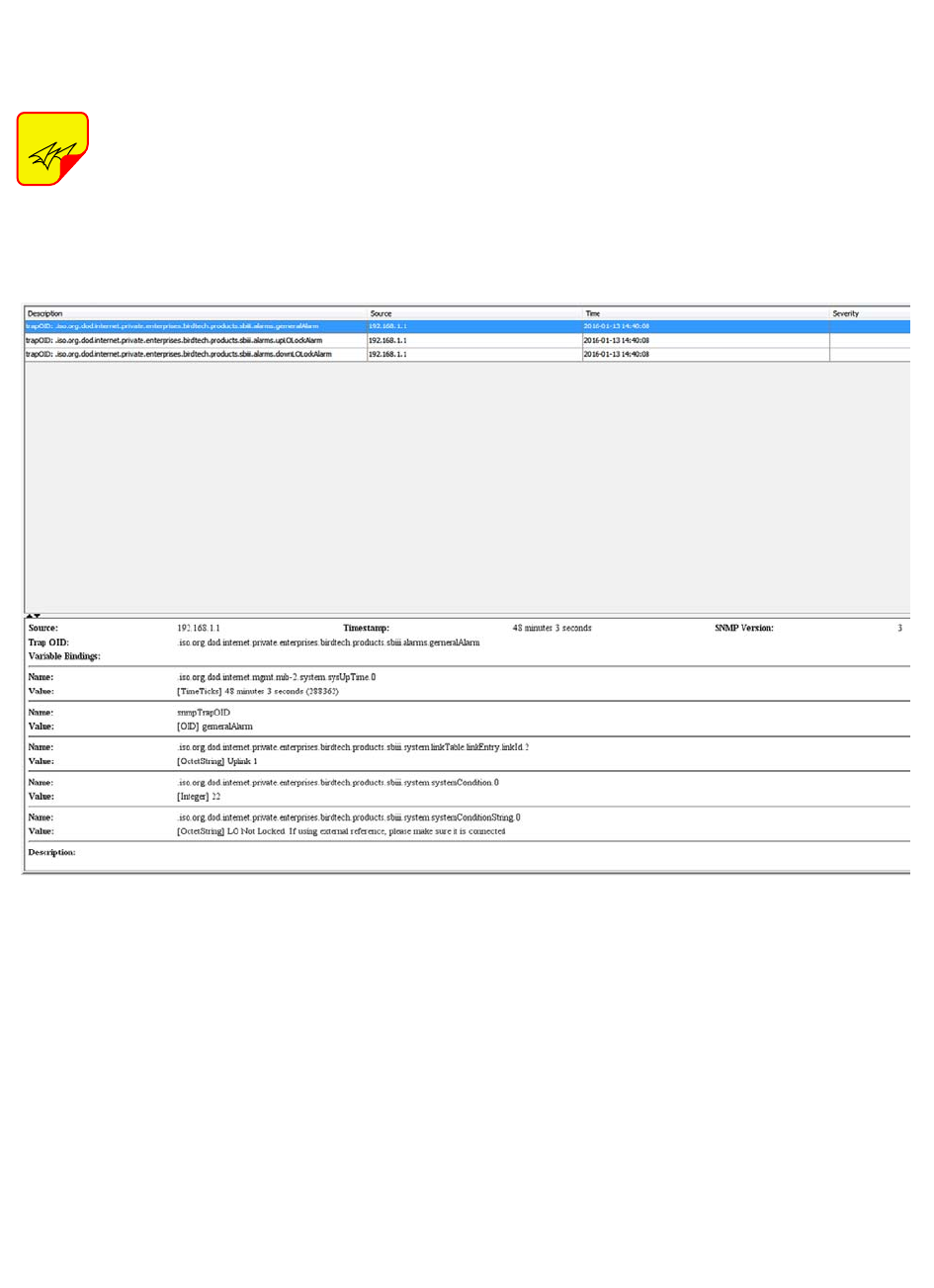
When a qualifying event occurs in the booster a
trap is formulated and sent to the destination com-
puter. A typical trap is shown in Figure 19. In the
example shown the trap messages are shown at
the top of the screen display. Three trap messages
have been received by this manager from a signal
booster. In this particular SNMP manager software
package if a trap message is selected the details of
that message are displayed in the lower portion of
the screen. The details show the raw message as it
was received by the manager while the upper box
shows the message after it has been interpreted by
the MIB files.
Creating an Alarm for Testing Purposes
In the example shown in figure 19 an alarm condi-
tion was generated in the booster in order to create
the trap messages shown. The booster was told to
generate its oscillator clock signals using an exter-
nal reference source but no external source was
connected to the booster. This is a quick and easy
way to create a temporary alarm for testing pur-
poses. This is accomplished via the Link Page dis-
cussed earlier in the manual. Select the ON radio
button labeled EXT 10 MHz Reference then click
the Submit button. Do not connect a signal source
to the external osc port on the control module. This
will cause the downlink and uplink oscillators in the
channel to shutdown and the booster will enter an
alarm condition. Please note that on-air signals will
be interrupted during this time. To clear the alarm
select the OFF radio button then click the Submit
TX RX Systems Inc. Manual 7-9485-1.9.1 10/26/17 Page 26
button and finally the Clear Errors button. This will
take the booster out of the alarm condition and
return it to normal operation.
IMPORTANT: The SNMP feature may
not send traps when the web page is
operational. It may hold the trap mes-
sages until the web page interface is
closed at which point it will then send
the traps to the destination comput-
ers.
NOTE
Figure 19: SNMP manager example.
TX RX Systems Inc. Manual 7-9485-1.9.1 10/26/17 Page 27
ETHERNET CONNECTIVITY
The front panel User Interface connector on the
booster provides for 10/100 BASE-T Ethernet con-
nection using the TCP-IP protocol. This product
feature allows access to a web-based interface for
programming the individual modules within the
booster. The web based interface requires a JAVA
runtime environment (version 1.6.0 or later) to be
installed on your laptop. The JAVA software can be
downloaded free of charge from the Sun Microsys-
tems website found at “http://java.com/en/down-
load/index.jsp”. The channelized booster is
shipped from the factory with a default IP address
of “192.168.1.1”.
Two connection schemes are discussed including a
direct connection from your laptop computer to the
booster front panel as well as connecting the
booster to a networked environment. A direct con-
nection (at the installation site) should be estab-
lished the first time you interface to the booster
using the fixed IP mentioned above. Once the initial
communications are established the IP address in
the booster can be changed to permit a networked
connection (from a remote site such as your office).
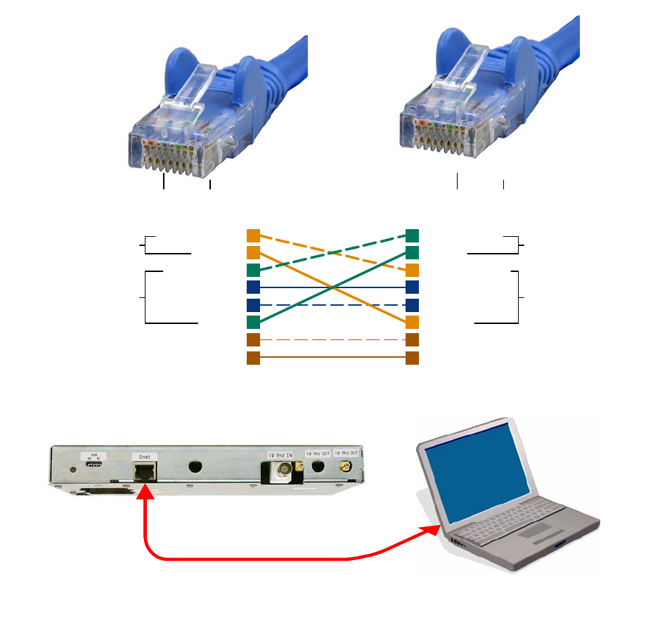
Direct Connection
Your initial connection to the booster system should
be a direct connection to the front panel using an
Ethernet crossover cable. Figure A1 shows the
proper way to interconnect the equipment as well
as the pinout for a CAT-5 crossover cable.
REQUIRED EQUIPMENT
Cat-5 Crossover Cable
Laptop Computer with a network interface card
installed. In addition, the JAVA run-time environ-
ment version 1.6.0 or later, and a web browser
such as Internet Explorer must also be installed on
the laptop.
PROCEDURE
To connect your laptop computer to the front panel
LAN port and access the web page interface, per-
form the following steps;
1) Insure the JAVA runtime environment software is
installed on your laptop.
2) Connect your laptop network port to the LAN
connector on the booster front panel using a
standard CAT-5 Crossover cable.
The front panel LAN connector
has two built-in bi-color status
LED’s which will aid you in estab-
lishing communications. The
meaning of each LED is shown in
Table A1.
3) The left-most (LINK) status LED built-in to the
LAN port connector should illuminate amber or
green indicating that a good physical connec-
tion is established between your computer and
the booster.
4) Insure that your laptop’s IP address is compati-
ble with the default address of the signal
booster system. This may require changes be
made to the Ethernet adaptor address on your
laptop (refer to Appendix B). Your laptop’s IP
address will need to be set to “192.168.1.2”
along with a subnet mask of “255.255.255.0”.
The right-most (ACTIVITY) status LED built-in
to the LAN port connector will turn amber or
green indicating good TCP-IP communications
are established between the laptop and the
booster.
5) Launch your web browser software on the lap-
top.
NOTE
APPENDIX A
Front Panel Ethernet Connectivity
LINK LED (left side) ACTIVITY LED (right side)
Color Meaning Color Meaning
Off No Link Off No Activity
Amber 10 Mbps Amber Half-Duplex
Green 100 Mbps Green Full-Duplex
Table A1: LAN port status LED’s
TX RX Systems Inc. Manual 7-9485-1.9.1 10/26/17 Page 28
6) In your web browsers address box type-in the
address of the booster “http://192.168.1.1” and
press the ENTER key. The web page interface
to the booster should appear in your laptop’s
browser window. When you launch the web
page you may notice that the JAVA applet will
load first.
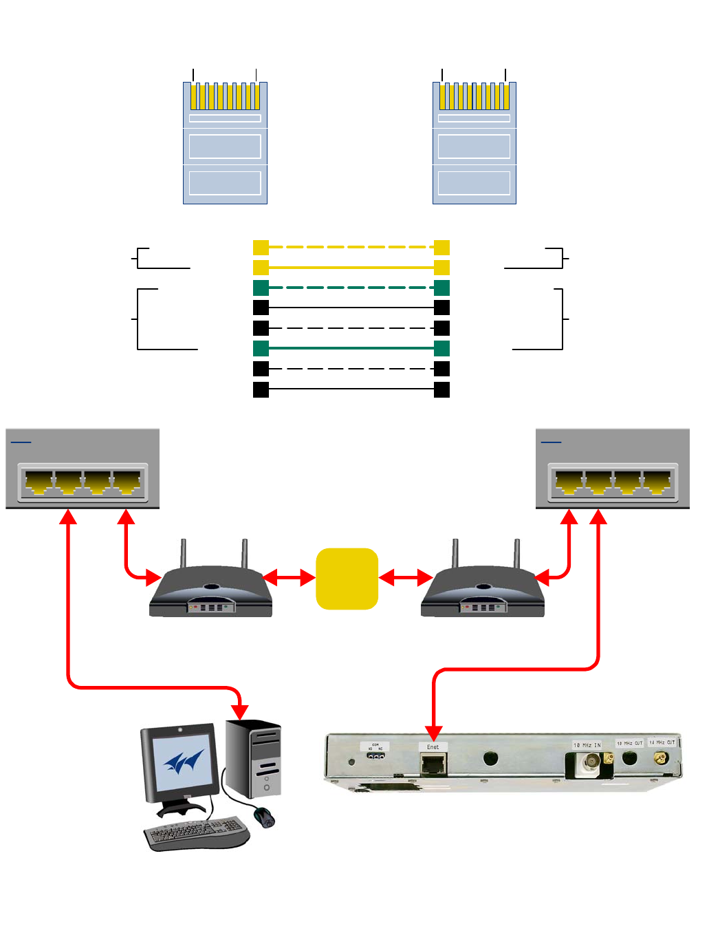
Networked Connection
Before attempting a networked connection to the
signal booster system consult with your IT support
personnel for information concerning the correct IP
address to use and any additional connectivity
issues such as firewalls. Once you have the correct
IP address you will need to direct connect to the
booster system as discussed in the earlier section
of this appendix and reconfigure the booster LAN
port with this new address. You can then connect
the signal booster system using a straight-through
CAT-5 cable to the networked environment and
interface to it from a remote computer. Figure A2
shows the proper way to interconnect the equip-
ment for a networked connection as well as the
pinout for a straight-thru CAT-5 cable.
REQUIRED EQUIPMENT
Cat-5 Straight-thru Cable
Laptop Computer with a network interface card
installed. In addition, the JAVA run-time environ-
ment version 1.6.0 or later, and a web browser
such as Internet Explorer must also be installed on
the laptop.
1
4
7
6
3
5
8
2
1
4
7
6
3
5
8
2
Orange/White
Orange
Green/White
Blue
Blue/White
Green
Brown/White
Brown
Green/White
Green
Orange/White
Blue
Blue/White
Orange
Brown/White
Brown
Transmit (1 & 2)
Receive (3 & 6) Transmit (3 & 6)
Receive (1& 2)
Pins 4, 5, 7 and 8 are not used
Pin Pin
CAT-5 Cross-Over Cable
18 18
Figure A1: Direct connection to the booster using crossover cable.
TX RX Systems Inc. Manual 7-9485-1.9.1 10/26/17 Page 29
1
4
7
6
3
5
8
2
1
4
7
6
3
5
8
2
Orange/White
Orange
Green/White
Blue
Blue/White
Green
Brown/White
Brown
Orange/White
Orange
Green/White
Blue
Blue/White
Green
Brown/White
Brown
Transmit (1 & 2)
Receive (3 & 6) Transmit (3 & 6)
Receive (1& 2)
Pins 4, 5, 7 and 8 are not used
Pin Pin
1234
4 Port Ethernet Hub
1234
4 Port Ethernet Hub
CAT-5
Straight-Through
Cable
Modem/Router Modem/Router
Remote PC System
Internet
18 18
Figure A2: WAN connection to the booster using straight-through cable.

TX RX Systems Inc. Manual 7-9485-1.9.1 10/26/17 Page 30
PROCEDURE
Before a networked connection can be established,
the booster LAN Port must be changed to an IP
address that’s compatible with your network. If you
are unsure how to determine this address check
with your IT support personnel. To connect the
booster LAN port to a networked environment and
access the web page interface, perform the follow-
ing steps;
1) Change the boosters LAN port IP address. To
do this, direct connect your laptop to the
booster as discussed in the earlier section of
this appendix titled “Direct Connection” and fol-
low steps 1 through 4.
2) Launch the configuration Applet in your web
browser.
3) Click the “Admin” tab at the top of the interface
display screen.
4) To be safe, take note of the settings currently
displayed.
5) Select the “User Static IP” radio button.
6) Enter the following settings provided by your
network administrator;
A) IP Address
B) Subnet Mask
C) Gateway Address
7) Click the “Submit” button to apply the changes.
8) Once the changes have been successfully
applied close your web browser.
9) Launch the configuration Applet in your web
browser using the newly entered IP address.
TX RX Systems Inc. Manual 7-9485-1.9.1 10/26/17 Page 31
When you initially direct connect your laptop ser-
vice computer to the booster it will be necessary to
change the computers IP address. The procedure
for doing this varies depending upon your operat-
ing system. As an example, this appendix illus-
trates how to make the change using the Microsoft
XP operating system. The procedure for other
operating systems will vary slightly from this exam-
ple. Consult with your IT support personnel if
needed. To change the IP address (assuming the
Microsoft XP operating system is being used) per-
form the following in a step-by-step fashion;
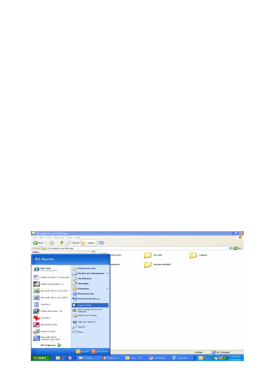
1) Select “Start” from the status menu.
2) Single click the “Control Panel” choice from the
“Start” pop-up menu as shown in Figure B1.
3) From the “Control Panel” icon selections double
click on the “Network Connections” icon. Refer
to Figure B2.
4) When the “Network Connections” folder opens
double click on the “Local Area Connection”
icon. See Figure B3.
5) The “Local Area Connection Status” box will
open. Single click the “Properties” tab as shown
in Figure B4. Note: If you do not have the cable
connected between the service computer and
the booster front panel the “Local Area Connec-
tion Status” box will not open. Instead proceed
to step 6.
6) The “Local Area Connection Properties” box will
open. Use the arrow buttons to scroll down the
list until the “Internet Protocol (TCP/IP)” choice
is highlighted as shown in Figure B5. Click the
“Properties” tab at the right-center of the box.
7) Select the “Use the following IP address” bub-
ble. Make sure the circle is filled-in. Refer to
Figure B6.
8) Enter the new IP address and subnet mask val-
ues as shown in Figure B7. To interface your
computer to the signal booster use an IP
address of “192.168.1.2” and a subnet mask of
“ 255.255.255.0”.
9) Click on the “OK” tab to initiate the changes.
This completes the procedure. Close any open
boxes.
APPENDIX B
Changing Your Service Computers IP Address
Figure B1: Choose the “Control panel” icon.
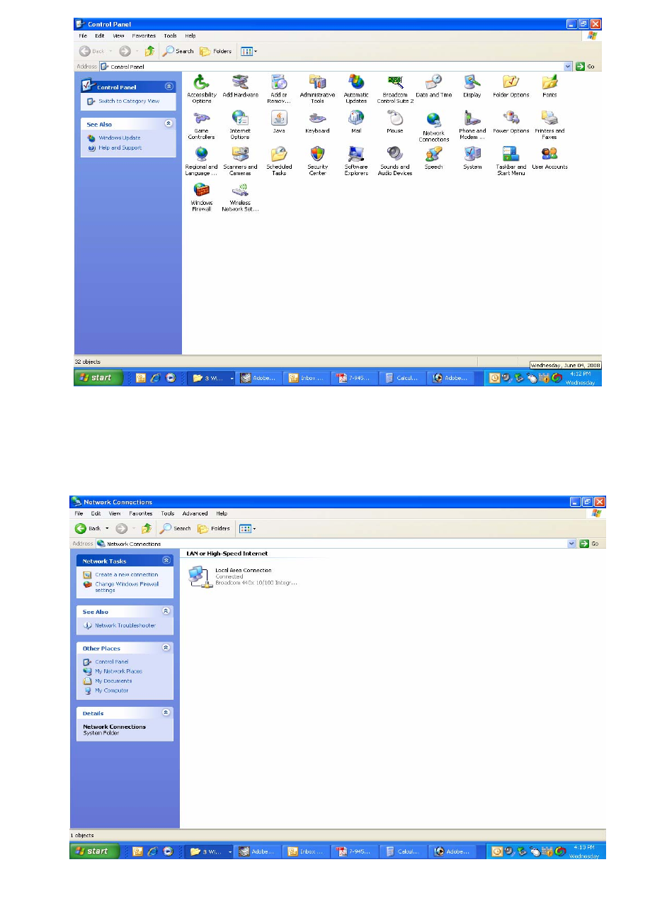
TX RX Systems Inc. Manual 7-9485-1.9.1 10/26/17 Page 32
Figure B2: Select the “Network Connections” icon.
Figure B3: Select the “Local Area Connection” icon.
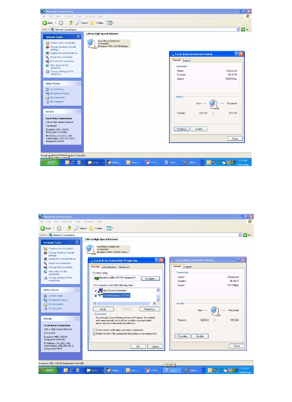
TX RX Systems Inc. Manual 7-9485-1.9.1 10/26/17 Page 33
Figure B4: Select the “Properties” tab.
Figure B5: Make sure the “Internet Protocol (TCP/IP)” choice is highlighted. Then select “OK”.
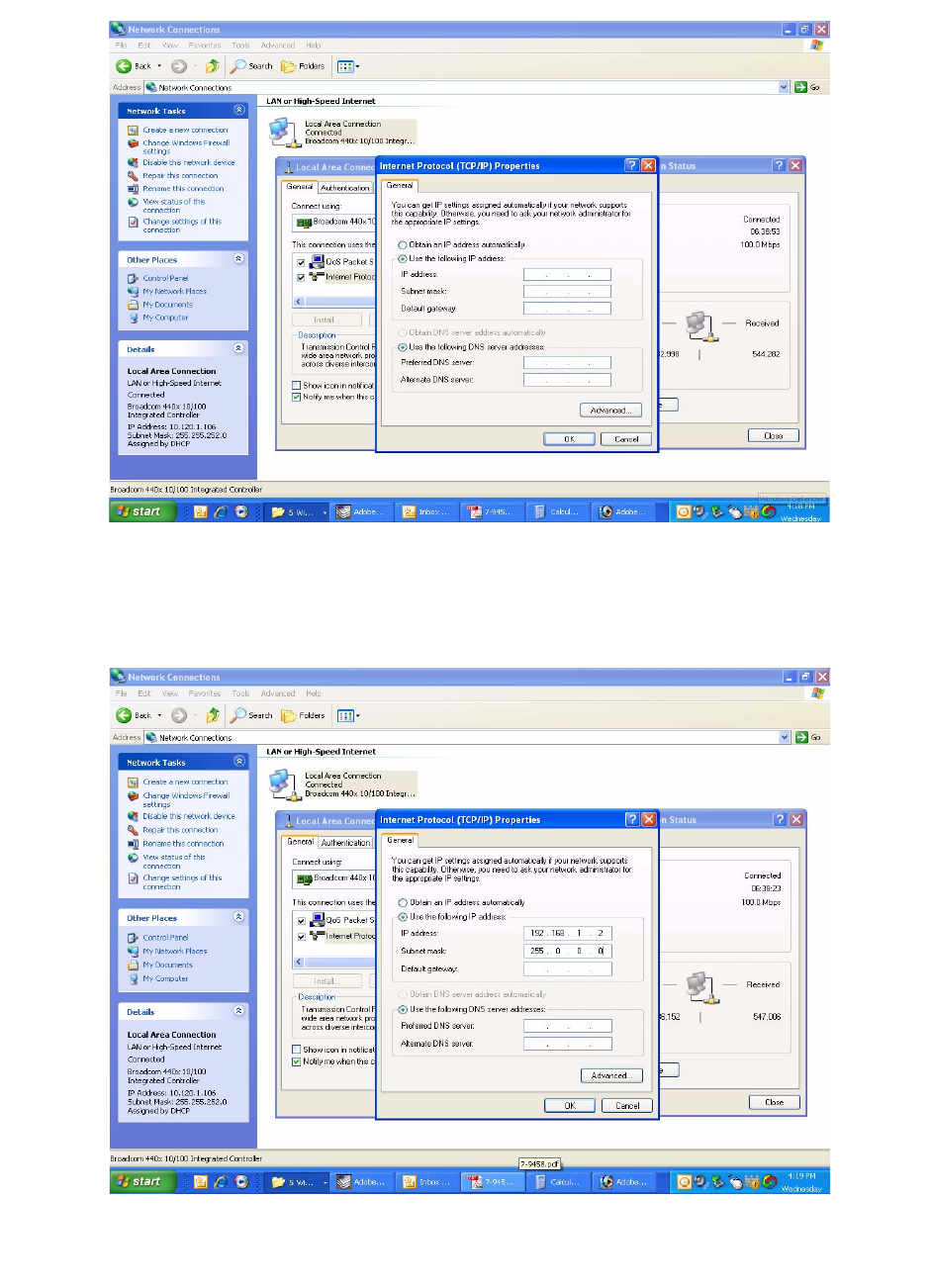
TX RX Systems Inc. Manual 7-9485-1.9.1 10/26/17 Page 34
Figure B6: Select “Use the Following IP Address”.
Figure B7: Enter the new IP Address and Subnet mask Values.

TX RX Systems Inc. Manual 7-9485-1.9.1 10/26/17 Page 35
Return Loss vs. VSWR
Return Loss VSWR
30 1.06
25 1.11
20 1.20
19 1.25
18 1.28
17 1.33
16 1.37
15 1.43
14 1.50
13 1.57
12 1.67
11 1.78
10 1.92
92.10
Watts to dBm
Watts dBm
300 54.8
250 54.0
200 53.0
150 51.8
100 50.0
75 48.8
50 47.0
25 44.0
20 43.0
15 41.8
10 40.0
537.0
436.0
334.8
233.0
130.0
dBm = 10log P/1mW
Where P = power (Watt)
Insertion Loss
Input Power (Watts)
50 75 100 125 150 200 250 300
325 38 50 63 75 100 125 150
2.5 28 42 56 70 84 112 141 169
232 47 63 79 95 126 158 189
1.5 35 53 71 88 106 142 177 212
140 60 79 99 119 159 199 238
.5 45 67 89 111 134 178 223 267
Output Power (Watts)
Insertion Loss
Free Space Loss
Distance (miles)
.25 .50 .75 12510 15
150 68 74 78 80 86 94 100 104
220 71 77 81 83 89 97 103 107
460 78 84 87 90 96 104 110 113
860 83 89 93 95 101 109 115 119
940 84 90 94 96 102 110 116 120
1920 90 96 100 102 108 116 122 126
Free Space Loss (dB)
Free space loss = 36.6 + 20log D + 20log F
Where D = distance in miles and F = frequency in MHz
Frequency (MHz)

TX RX Systems Inc. Manual 7-9485-1.9.1 10/26/17 Page 36
8625 Industrial Parkway, Angola, NY 14006 Tel: 716-549-4700 Fax: 716-549-4772 sales@birdrf.com www.bird-technologies.com