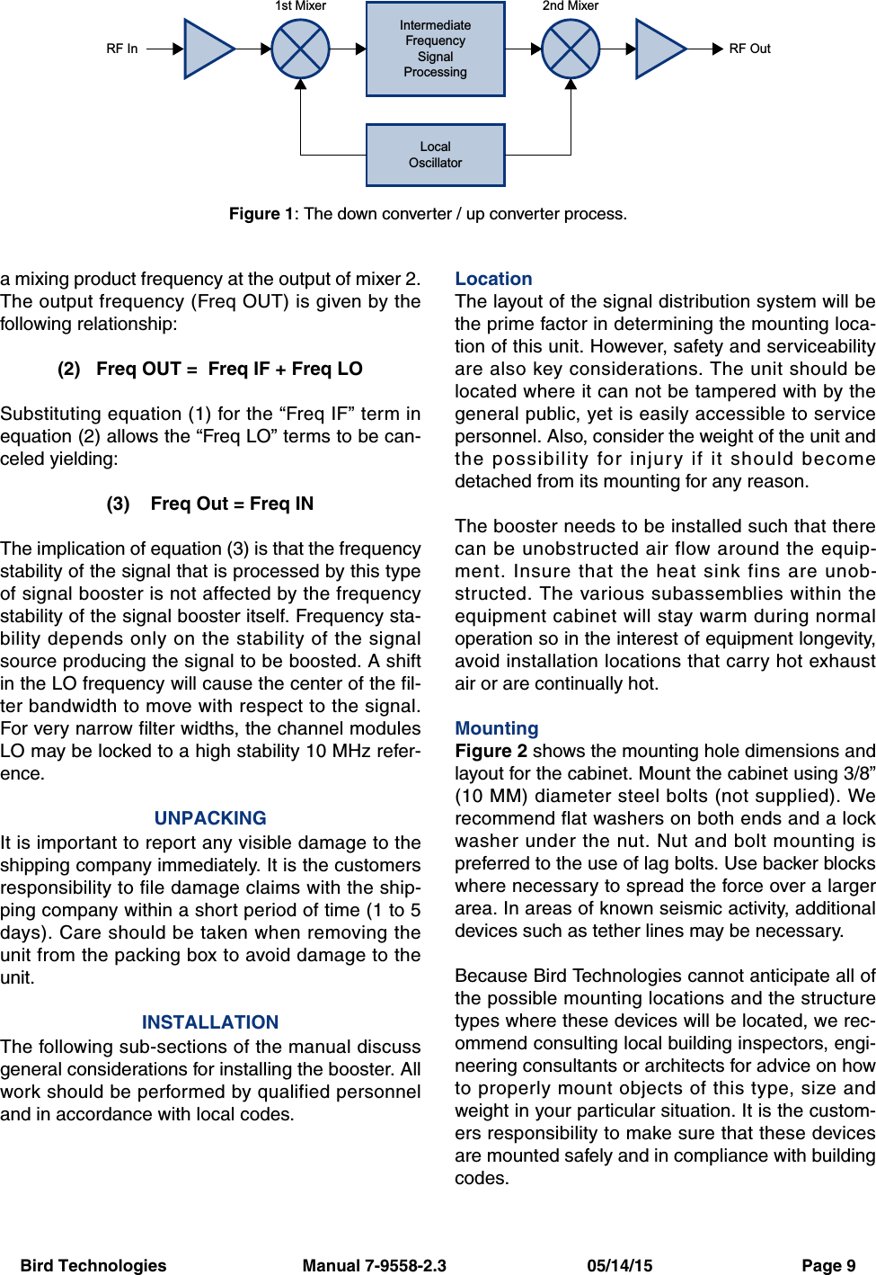
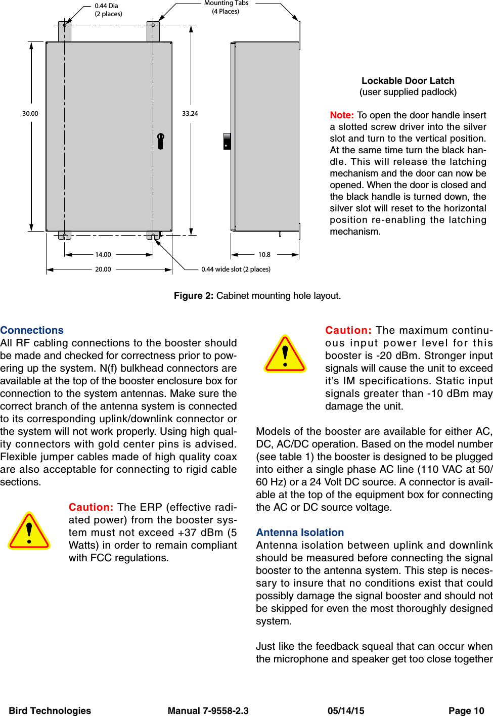
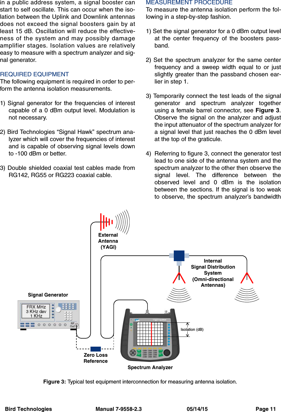
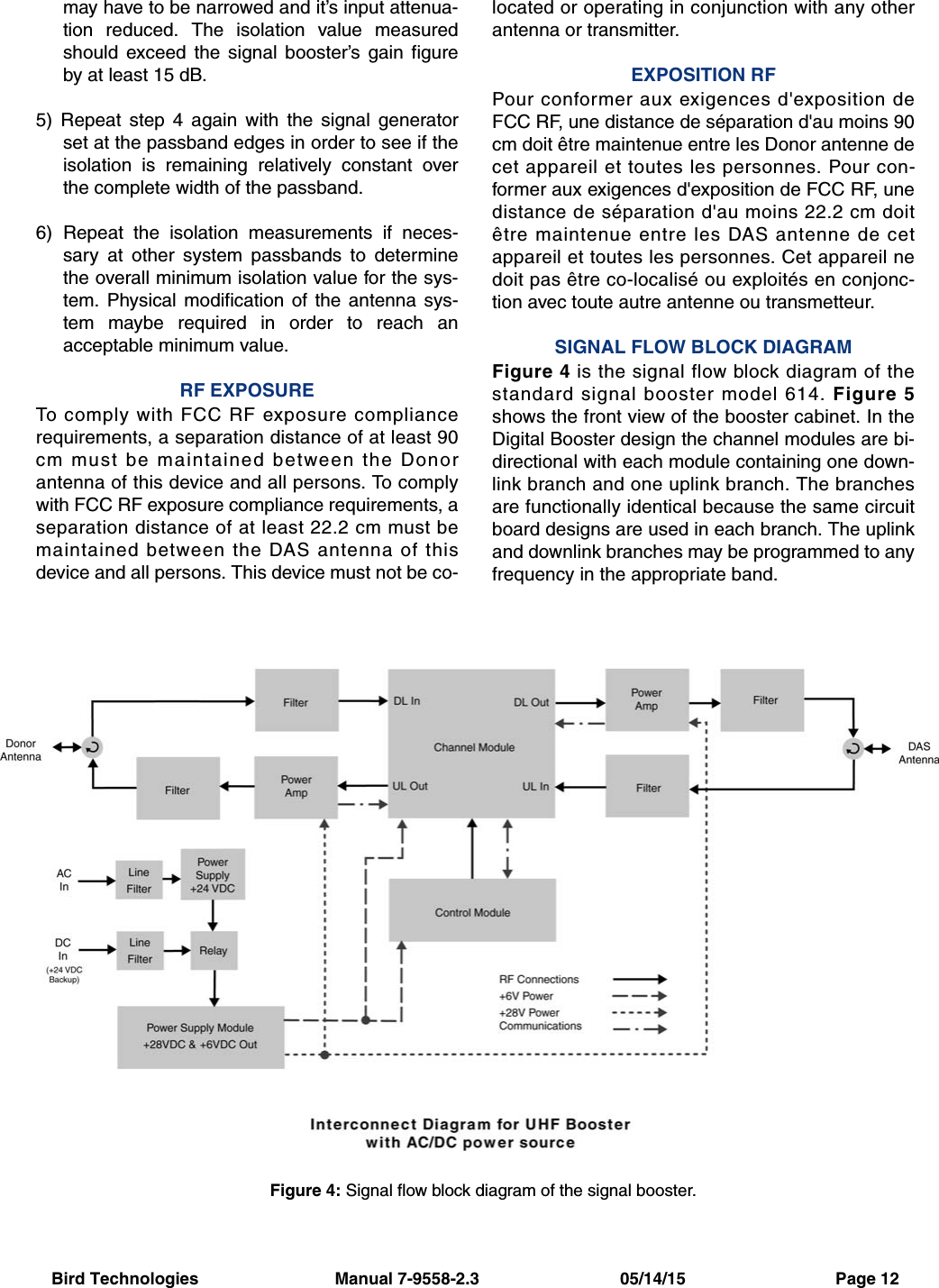
Bird Technologies Group 61470 UHF Digital Signal Booster User Manual 9558S1 2 3

Bird Technologies Group UHF Digital Signal Booster 9558S1 2 3

Manual Rev6

Bird Technologies                             Manual 7-9558-2.3                              05/14/15                                Page 18625 Industrial Parkway, Angola, NY 14006    Tel: 716-549-4700    Fax: 716-549-4772    sales@birdrf.com    www.bird-technologies.com Installation and Operation Manual forthe SBIII Digital Signal BoosterModel 614Manual Part Number7-9558-2.3DIGITAL TECHNOLOGYWARNING: This is NOT a consumer device. It is designed for installation byFCC Licensees and Qualified Installers. You must have an FCC license orexpress consent of an FCC Licensee to operate this device. This booster canbe configured as either a Class A or Class B signal booster. If configured as aClass B signal booster (as defined in 47 CFR 90.219), you MUST registerthis signal booster online at www.fcc.gov/signal-booster/registration. Unau-thorized use may result in significant forfeiture penalties, including penaltiesin excess of $100,000 for each continuing violation.
Bird Technologies                             Manual 7-9558-2.3                              05/14/15                                Page 2WarrantyThis warranty applies for five years fr  om shippi  ng date  TX RX Systems Inc. warrants its products to be free from defect in material and workmanship at the time of shipment.Our obligation under warranty is limited to replacement or repair, at our option, of any such products that shall havebeen defective at the time of manufacture. TX RX Systems Inc. reserves the right to replace with merchandise ofequal performance although not identical in every way to that originally sold. TX RX Systems Inc. is not liable for dam-age caused by lightning or other natural disasters. No product will be accepted for repair or replacement without ourprior written approval. The purchaser must prepay all shipping charges on returned products. TX RX Systems Inc.shall in no event be liable for consequential damages, installation costs or expense of any nature resulting from thepurchase or use of products, whether or not they are used in accordance with instructions. This warranty is in lieu of allother warranties, either expressed or implied, including any implied warranty or merchantability of fitness. No repre-sentative is authorized to assume for TX RX Systems Inc. any other liability or warranty than set forth above in con-nection with our products or services.TERMS AND CONDITIONS OF SALE PRICES AND TERMS:Prices are FOB seller’s plant in Angola, NY domestic packaging only, and are subject to change without notice. Fed-eral, State and local sales or excise taxes are not included in prices. When Net 30 terms are applicable, payment isdue within 30 days of invoice date. All orders are subject to a $100.00 net minimum.QUOTATIONS:Only written quotations are valid.ACCEPTANCE OF ORDERS:Acceptance of orders is valid only when so acknowledged in writing by the seller.SHIPPING:Unless otherwise agreed at the time the order is placed, seller reserves the right to make partial shipments for whichpayment shall be made in accordance with seller’s stated terms. Shipments are made with transportation charges col-lect unless otherwise specified by the buyer. Seller’s best judgement will be used in routing, except that buyer’s routingis used where practicable. The seller is not responsible for selection of most economical or timeliest routing.CLAIMS:All claims for damage or loss in transit must be made promptly by the buyer against the carrier. All claims for shortagesmust be made within 30 days after date of shipment of material from the seller’s plant.SPECIFICATION CHANGES OR MODIFICATIONS:All designs and specifications of seller’s products are subject to change without notice provided the changes or modifi-cations do not affect performance.RETURN MATERIAL:Product or material may be returned for credit only after written authorization from the seller, as to which seller shallhave sole discretion. In the event of such authorization, credit given shall not exceed 80 percent of the original pur-chase. In no case will Seller authorize return of material more than 90 days after shipment from Seller’s plant. Creditfor returned material is issued by the Seller only to the original purchaser.ORDER CANCELLATION OR ALTERATION:Cancellation or alteration of acknowledged orders by the buyer will be accepted only on terms that protect the selleragainst loss.NON WARRANTY REPAIRS AND RETURN WORK:Consult seller’s plant for pricing. Buyer must prepay all transportation charges to seller’s plant. Standard shipping pol-icy set forth above shall apply with respect to return shipment from TX RX Systems Inc. to buyer.DISCLAIMER Product part numbering in photographs and drawings is accurate at time of printing. Part number labels on TX RXproducts supersede part numbers given within this manual. Information is subject to change without notice.
Bird Technologies                             Manual 7-9558-2.3                              05/14/15                                Page 3Symbols Commonly UsedNOTEVIDEOWARNING !!!CAUTION or ATTENTIONImportant InformationTraining Video AvailableHeavy LiftingHigh VoltageHot SurfaceESD  Electrostatic DischargeElectrial Shock HazardSafety Glasses RequiredManual Part Number 7-9558Copyright © 2015 Bird TechnologiesFirst Printing: June 2014Version Number Version Date1 06/16/141.1 07/14/141.2 09/23/141.3 11/13/142.0 02/23/152.1 04/07/152.2 04/29/152.3 05/14/15
Bird Technologies                             Manual 7-9558-2.3                              05/14/15                                Page 4Table of ContentsOverview ...............................................................................................................7  Down / Up Conversion.........................................................................................8Unpacking ............................................................................................................9Installation ............................................................................................................9   Location  .............................................................................................................9   Mounting .............................................................................................................9   Connections......................................................................................................10Antenna Isolation  .............................................................................................10  Required Equipment .......................................................................................11  Measurement Procedure.................................................................................11RF Exposure (Exposition RF)  ..........................................................................12Signal Flow Block Diagram ..............................................................................12  Uplink and Downlink Input Signals.....................................................................13  Channel Module.................................................................................................13  Uplink and Downlink Output Signals..................................................................15System Setup .....................................................................................................15Operation ............................................................................................................15  Alarm Form-C Contacts .....................................................................................16  NFPA Compliant Signal Booster........................................................................16 Communicating with the Signal Booster........................................................17  System Summary Submenu ..............................................................................17  Control Panel Submenu.....................................................................................17  Filters Tab ..........................................................................................................18  Filter Detail Tab .................................................................................................18    Design Button ..................................................................................................19    Status Area ......................................................................................................20  Link Tab .............................................................................................................20  Command Buttons ..........................................................................................21  Link and Settings Area ....................................................................................21  Status Area .....................................................................................................21FFT Tab ............................................................................................................22System Tab .......................................................................................................22  Oscillation Detection........................................................................................23  Class B Enable................................................................................................23Network Configuration Submenu ......................................................................24User Administration Submenu...........................................................................25SNMP Configuration Submenu .........................................................................25  Initial Setup .....................................................................................................25  Trap Receiver GUI ..........................................................................................26Maintenance and Repair....................................................................................27  Power Amplifier Replacement............................................................................27  Channel Module Replacement ..........................................................................28  Control Module Replacement ............................................................................28  Power Supply Replacement ..............................................................................29
Bird Technologies                             Manual 7-9558-2.3                              05/14/15                                Page 5Figures and TablesFigure 1: The Down / Up Converter Process .......................................................9Figure 2: Cabinet Mounting  ...............................................................................10Figure 3: Measuring Antenna Isolation ...............................................................11Figure 4: Signal Flow Block Diagram..................................................................12Figure 5: Booster Cabinet Front View.................................................................13Figure 6: On/Off Circuit Breakers .......................................................................15Figure 7: Alarm Form-C Contacts.......................................................................15Figure 8: Enet Connector....................................................................................16Figure 9: System Summary Page.......................................................................17Figure 10: Filters Page .......................................................................................18Figure 11: Class A Limit Exceeded Warning Message.......................................18Figure 12: Filter Detail Page ...............................................................................19Figure 13: Invalid Filter Settings Warning Message ...........................................19Figure 14: Design Filter Interactive Display ........................................................20Figure 15: Link Page...........................................................................................21Figure 16: FFT Page...........................................................................................22Figure 17: System Page .....................................................................................23Figure 18: Starting Class B Operation Message ................................................23Figure 19: Network Configuration Display ..........................................................24Figure 20: The Admin Page................................................................................24Figure 21: SNMP Configuration Display .............................................................25Figure 22: Trap Receiver GUI Interface ..............................................................26Figure 23: Trap Details........................................................................................26Figure 24: Removing the Power Amplifier...........................................................27Figure 25: Removing the Channel Module .........................................................28Figure 26: Removing the Power Supply..............................................................29Table 1: Model number nomenclature...................................................................7Table 2: Specifications ..........................................................................................8Table 3: Subassembly LED Descriptions ............................................................14Table 4: Integer Fault Definitions.........................................................................26AppendixesAppendix A: Front Panel Ethernet Connectivity .................................................30Ethernet Connectivity ..........................................................................................30  Direct Connection ..............................................................................................30    Required Equipment ........................................................................................30    Procedure ........................................................................................................30  Networked Connection ......................................................................................31    Required Equipment ........................................................................................31    Procedure ........................................................................................................33Appendix B: Changing Your Service Computers IP Address.............................34
Bird Technologies                             Manual 7-9558-2.3                              05/14/15                                Page 6For Class A or Class B Unintentional RadiatorsThis equipment has been tested and found to comply with the limits for a Class A or Class B digital device, pursuant toPart 15 of the FCC rules. These limits are designed to provide reasonable protection against harmful interference whenthe equipment is operated in a commercial environment. This equipment generates, uses, and can radiate radio fre-quency energy and, if not installed and used in accordance with the instruction manual, may cause harmful interferenceto radio communications. Operation of this equipment in a residential area is likely to cause harmful interference inwhich the user will be required to correct the interference at his own expense.Pour Classe-A ou Classe-B Radiateurs InvolontairesCet équipement a été testé et jugé conforme avec les limites de la Classe-A ou Classe-B des appareils numériques,suivants à la Partie 15 des règlements de la FCC. Ces limites sont conçues pour fournir une protection raisonnable con-tre les interférences dangereuses lorsque l'équipement est utilisé dans un environnement commercial. Cet équipementgénère, utilise et peut émettre des fréquences radio et, s'il n'est pas installé et utilisé conformément aux instructions dumanuel, ceci peut causer des interférences dangereuses aux communications radio. Le fonctionnement de cet équipe-ment dans une zone résidentielle est susceptible de causer des interférences mauvaises dans lequel l'utilisateur seratenu pour responsable de corriger l'interférence à sa propre discrétion.WARNING: Changes or modifications which are not expressly approved by Bird Technologiescould void the user’s authority to operate the equipment.AVERTISSEMENT: Les changements ou modifications qui ne sont pas approuvés par Bird Tech-nologies pourrait annuler l'autorité de l'utilisateur de faire fonctionner l'équipement.ATTENTION: This device complies with Part 15 of the FCC rules. Operation is subject to the following twoconditions: (1) this device may not cause harmful interference and (2) this device must accept any interfer-ence received, including interference that may cause undesired operation.ATTENTION: Cet appareil est conforme à la Partie 15 des règlements de la FCC. L'opération doit se con-former aux deux conditions suivantes: (1) cet appareil ne peut causer d'interférences nuisibles et (2) cetappareil doit accepter toute interférence reçue, y compris les interférences qui peuvent provoquer un fonc-tionnement indésirable.
Bird Technologies                             Manual 7-9558-2.3                              05/14/15                                Page 7OVERVIEWSignal boosters extend radio coverage into areaswhere abrupt propagation losses prevent reliablecommunication. The system receives an RF signal,raises its power level, and couples it to an antennaso that it can be re-radiated. The Bird Technologies614 family of signal boosters is designed to oper-ate in either the 450 - 470 MHz range or the 470 -488 MHz range. The system is based on a moduledesign with each module capable of handling 14 or30 filters in the uplink and downlink direction. Thesignal booster is available in a variety of configura-tions as shown in Table 1. The product model num-ber is used to describe each configurationavailable. Model number nomenclature isdescribed in table 1.The size of the system can be tailored to the cus-tomers needs by increasing or decreasing thenumber of filters used. Each module is bi-direc-tional with one downlink and one uplink signalbranch. Each of the two branches in a module areindependently tunable to their required pass fre-quencies via software interface. The booster uses614-XX-YY-UD-Z-P-Options (nomenclature breakdown)614 Product Description UHF Digital Signal BoosterXXDesignates operating frequency band70 = 450 - 470 MHz70A = 470 - 488 MHzYYDesignates how many modules used and number of filters availableA = 1 module with 14 filtersB = 1 module with 30 filtersAA = 2 modules with 14 filters eachBB = 2 modules with 30 filters eachAB = 1 module with 14 filters and 1 module with 30 filtersBA = 1 module with 30 filters and 1 module with 14 filtersUDDesignates the type of output for the uplink and downlinkHH = high power uplink and downlinkHL = high power uplink and low power downlinkLH = low power uplink and high power downlinkLL = low power for both uplink and downlinkFH = fiber output uplink and high power downlinkFL = fiber output uplink and low power downlinkHF = high power uplink and fiber output downlinkLF = low power uplink and fiber output downlinkDP = dual port head-endDPR = dual port remote-endZDesignates mounting styleG1 = Grey SteelG2 = StainlessN = NFPA / Red SteelPPower OptionsB = AC with DC backup (standard)D = DC only (24 VDC option)A = AC only (option)OptionsDesignates the options that have been addedBlank = no options addedP = 10 MHz high precision reference Table 1: Model number nomenclature.
Bird Technologies                             Manual 7-9558-2.3                              05/14/15                                Page 8digital processing techniques to provide a widerange of filter choices to the end user. It is possibleto program digital filters as narrow as 5 KHz and aswide as 1.5 MHz centered at any frequency withinthe licensed range.The SBIII Digital Signal Booster is capable of oper-ating as either a Class A booster (no filters greaterthan 75 KHz passband width) or as a Class Bbooster (having filters with a greater than 75 KHzpassband width). The boosters operating class (Aor B) is user determined via configuration. Class Boperation must be enabled by the customer andthe customer is responsible for registering abooster operated as Class B with the FCC. Systemspecifications for the 614 family of signal boostersare listed in Table 2.Down / Up ConversionA signal booster has much in common with asuperheterodyne (superhet) receiver. The incom-ing signal is converted to a lower frequency so thatsingle channel selectivity can be obtained. It is thenfiltered. Unlike the superhet receiver however, thesignal is not demodulated. Instead, it is up-con-verted back to its original frequency where it is fur-ther amplified to reach a useful power level.Figure 1 shows a simplified block diagram thatillustrates the down/up conversion principle. Anincoming signal at (Freq IN) is amplified andapplied to the first mixer along with a signal from alocal oscillator (Freq LO). A third signal at an inter-mediate frequency (Freq IF) is produced as a resultof the mixing. The intermediate frequency is givenby the following relationship:(1)   Freq IF =  Freq IN - Freq LOThe IF signal from the mixer then passes throughdigital filtering with single channel bandwidthbefore being amplified and passed on to the sec-ond mixer. The second mixer also receives thesame local oscillator signal (Freq LO). The result isParameter SpecificationFrequency Range (MHz) 450 - 470 MHz  ;  470 - 488 MHzNumber of Carriers per ModuleLow Density ModelHigh Density Model14 uplink and downlink30 uplink and downlinkGainLow Power VersionHigh Power Version80 dB (max)95 dB (max)Maximum RF Bandwidth450 - 470 MHz module470 - 488 MHz module3 MHz1.5 MHzOutput LevelLow PowerHigh Power22 dBm composite (max)34 dBm composite (max)Maximum Continuous Input Level Operational: -20 dBmStatic w/o damage: -10dBmRF In/Out Impedance 50 OhmsAlarms Form-C Contacts and SNMP v3Power 90 - 250 VAC, 50/60 Hzwith +24 VDC back-upOperating Temperature Range -30°C to +60°C95% RH (non-condensing)Table 2: Specifications for the UHF SBIII system.
Bird Technologies                             Manual 7-9558-2.3                              05/14/15                                Page 9a mixing product frequency at the output of mixer 2.The output frequency (Freq OUT) is given by thefollowing relationship:(2)   Freq OUT =  Freq IF + Freq LOSubstituting equation (1) for the “Freq IF” term inequation (2) allows the “Freq LO” terms to be can-celed yielding:(3)    Freq Out = Freq INThe implication of equation (3) is that the frequencystability of the signal that is processed by this typeof signal booster is not affected by the frequencystability of the signal booster itself. Frequency sta-bility depends only on the stability of the signalsource producing the signal to be boosted. A shiftin the LO frequency will cause the center of the fil-ter bandwidth to move with respect to the signal.For very narrow filter widths, the channel modulesLO may be locked to a high stability 10 MHz refer-ence.UNPACKINGIt is important to report any visible damage to theshipping company immediately. It is the customersresponsibility to file damage claims with the ship-ping company within a short period of time (1 to 5days). Care should be taken when removing theunit from the packing box to avoid damage to theunit.INSTALLATIONThe following sub-sections of the manual discussgeneral considerations for installing the booster. Allwork should be performed by qualified personneland in accordance with local codes.LocationThe layout of the signal distribution system will bethe prime factor in determining the mounting loca-tion of this unit. However, safety and serviceabilityare also key considerations. The unit should belocated where it can not be tampered with by thegeneral public, yet is easily accessible to servicepersonnel. Also, consider the weight of the unit andthe possibility for injury if it should becomedetached from its mounting for any reason.The booster needs to be installed such that therecan be unobstructed air flow around the equip-ment. Insure that the heat sink fins are unob-structed. The various subassemblies within theequipment cabinet will stay warm during normaloperation so in the interest of equipment longevity,avoid installation locations that carry hot exhaustair or are continually hot.MountingFigure 2 shows the mounting hole dimensions andlayout for the cabinet. Mount the cabinet using 3/8”(10 MM) diameter steel bolts (not supplied). Werecommend flat washers on both ends and a lockwasher under the nut. Nut and bolt mounting ispreferred to the use of lag bolts. Use backer blockswhere necessary to spread the force over a largerarea. In areas of known seismic activity, additionaldevices such as tether lines may be necessary.Because Bird Technologies cannot anticipate all ofthe possible mounting locations and the structuretypes where these devices will be located, we rec-ommend consulting local building inspectors, engi-neering consultants or architects for advice on howto properly mount objects of this type, size andweight in your particular situation. It is the custom-ers responsibility to make sure that these devicesare mounted safely and in compliance with buildingcodes.IntermediateFrequencySignalProcessing1st Mixer 2nd MixerRF OutRF InLocalOscillatorFigure 1: The down converter / up converter process.
Bird Technologies                             Manual 7-9558-2.3                              05/14/15                                Page 10ConnectionsAll RF cabling connections to the booster shouldbe made and checked for correctness prior to pow-ering up the system. N(f) bulkhead connectors areavailable at the top of the booster enclosure box forconnection to the system antennas. Make sure thecorrect branch of the antenna system is connectedto its corresponding uplink/downlink connector orthe system will not work properly. Using high qual-ity connectors with gold center pins is advised.Flexible jumper cables made of high quality coaxare also acceptable for connecting to rigid cablesections.Caution: The ERP (effective radi-ated power) from the booster sys-tem must not exceed +37 dBm (5Watts) in order to remain compliantwith FCC regulations.Caution: The maximum continu-ous input power level for thisbooster is -20 dBm. Stronger inputsignals will cause the unit to exceedit’s IM specifications. Static inputsignals greater than -10 dBm maydamage the unit.Models of the booster are available for either AC,DC, AC/DC operation. Based on the model number(see table 1) the booster is designed to be pluggedinto either a single phase AC line (110 VAC at 50/60 Hz) or a 24 Volt DC source. A connector is avail-able at the top of the equipment box for connectingthe AC or DC source voltage.Antenna IsolationAntenna isolation between uplink and downlinkshould be measured before connecting the signalbooster to the antenna system. This step is neces-sary to insure that no conditions exist that couldpossibly damage the signal booster and should notbe skipped for even the most thoroughly designedsystem.Just like the feedback squeal that can occur whenthe microphone and speaker get too close together0.44 Dia(2 places)0.44 wide slot (2 places)33.2430.0014.00 10.820.00Mounting Tabs(4 Places)Figure 2: Cabinet mounting hole layout.Lockable Door Latch(user supplied padlock)Note: To open the door handle inserta slotted screw driver into the silverslot and turn to the vertical position.At the same time turn the black han-dle. This will release the latchingmechanism and the door can now beopened. When the door is closed andthe black handle is turned down, thesilver slot will reset to the horizontalposition re-enabling the latchingmechanism.
Bird Technologies                             Manual 7-9558-2.3                              05/14/15                                Page 11in a public address system, a signal booster canstart to self oscillate. This can occur when the iso-lation between the Uplink and Downlink antennasdoes not exceed the signal boosters gain by atleast 15 dB. Oscillation will reduce the effective-ness of the system and may possibly damageamplifier stages. Isolation values are relativelyeasy to measure with a spectrum analyzer and sig-nal generator.REQUIRED EQUIPMENTThe following equipment is required in order to per-form the antenna isolation measurements.1) Signal generator for the frequencies of interestcapable of a 0 dBm output level. Modulation isnot necessary.2) Bird Technologies “Signal Hawk” spectrum ana-lyzer which will cover the frequencies of interestand is capable of observing signal levels downto -100 dBm or better.3) Double shielded coaxial test cables made fromRG142, RG55 or RG223 coaxial cable.MEASUREMENT PROCEDURETo measure the antenna isolation perform the fol-lowing in a step-by-step fashion.1) Set the signal generator for a 0 dBm output levelat the center frequency of the boosters pass-band.2) Set the spectrum analyzer for the same centerfrequency and a sweep width equal to or justslightly greater than the passband chosen ear-lier in step 1.3) Temporarily connect the test leads of the signalgenerator and spectrum analyzer togetherusing a female barrel connector, see Figure 3.Observe the signal on the analyzer and adjustthe input attenuator of the spectrum analyzer fora signal level that just reaches the 0 dBm levelat the top of the graticule.4) Referring to figure 3, connect the generator testlead to one side of the antenna system and thespectrum analyzer to the other then observe thesignal level. The difference between theobserved level and 0 dBm is the isolationbetween the sections. If the signal is too weakto observe, the spectrum analyzer’s bandwidthSignal GeneratorExternalAntenna(YAGI)Spectrum AnalyzerIsolation (dB)Zero LossReferenceInternalSignal DistributionSystem(Omni-directionalAntennas)Figure 3: Typical test equipment interconnection for measuring antenna isolation.
Bird Technologies                             Manual 7-9558-2.3                              05/14/15                                Page 12may have to be narrowed and it’s input attenua-tion reduced. The isolation value measuredshould exceed the signal booster’s gain figureby at least 15 dB.5) Repeat step 4 again with the signal generatorset at the passband edges in order to see if theisolation is remaining relatively constant overthe complete width of the passband.6) Repeat the isolation measurements if neces-sary at other system passbands to determinethe overall minimum isolation value for the sys-tem. Physical modification of the antenna sys-tem maybe required in order to reach anacceptable minimum value.RF EXPOSURETo comply with FCC RF exposure compliancerequirements, a separation distance of at least 90cm must be maintained between the Donorantenna of this device and all persons. To complywith FCC RF exposure compliance requirements, aseparation distance of at least 22.2 cm must bemaintained between the DAS antenna of thisdevice and all persons. This device must not be co-located or operating in conjunction with any otherantenna or transmitter.EXPOSITION RFPour conformer aux exigences d'exposition deFCC RF, une distance de séparation d'au moins 90cm doit être maintenue entre les Donor antenne decet appareil et toutes les personnes. Pour con-former aux exigences d'exposition de FCC RF, unedistance de séparation d'au moins 22.2 cm doitêtre maintenue entre les DAS antenne de cetappareil et toutes les personnes. Cet appareil nedoit pas être co-localisé ou exploités en conjonc-tion avec toute autre antenne ou transmetteur.SIGNAL FLOW BLOCK DIAGRAMFigure 4 is the signal flow block diagram of thestandard signal booster model 614. Figure 5shows the front view of the booster cabinet. In theDigital Booster design the channel modules are bi-directional with each module containing one down-link branch and one uplink branch. The branchesare functionally identical because the same circuitboard designs are used in each branch. The uplinkand downlink branches may be programmed to anyfrequency in the appropriate band.Figure 4: Signal flow block diagram of the signal booster.
Bird Technologies                             Manual 7-9558-2.3                              05/14/15                                Page 13Uplink and Downlink Input SignalsUplink input signals are picked up by the DASantenna and are passed through an isolator beforebeing applied to a bandpass filter. The signals passthrough the filter and are fed into the uplink inputport of the channel module. Downlink input signalsare picked up by the Donor antenna and arepassed through an isolator before being applied toa bandpass filter. The signals pass through the fil-ter and are applied to the downlink input port of thechannel module.Channel ModuleThe uplink input signals and the downlink input sig-nals are applied to a down-converter board whenthey enter the channel module. Within the channelmodule input signals are down converted, digitized,and DSP filtering is performed. There are twostyles of Channel modules available, a 14 filter ver-Figure 5: Front view of the booster.Channel ModuleControlBoardPowerSupplyFilters PowerAmplifierCirculatorCirculatorLineFiltersCircuitBreakers
Bird Technologies                             Manual 7-9558-2.3                              05/14/15                                Page 14sion and a 30 filter version. After DSP filtering theanalog signal is recreated and up converted withan up-converter board to the original frequencybefore being output from the channel module at thedownlink and uplink output ports.Up converter boards are available in two differentstyles including low level and high level. If the sig-nal booster is a high-power model then a low levelup converter board is used in the channel module.If the booster is a low power model then high levelup converter boards are used. Signal booster mod-els that have the fiber-optic option installed in themhave enhanced down-converter boards that arecapable of dealing with the low level signals fromthe optical conversion.Location Label PossibleStates Causes Actionto takeBottom of channel module DL/UL PWR Green solid FPGA successfully loaded NoneBottom of channel module DL/UL PWR Off Issue with board Return to factoryBottom of channel module DL/UL COM Red flashes Exchanging data with con-trol board NoneBottom of channel module DL/UL COM Red solid Exchanging data with con-trol board NoneBottom of channel module DL/UL COM Off No data exchanging NoneBottom of channel module DL/UL COMAlways Off and it is expected to flashNo data exchanging Check cabling; return con-trol board to factoryBottom of channel module DL/UL DAC Red solid DAC overflow Lower output power settingBottom of channel module DL/UL DAC Off DAC normal operation NoneBottom of channel module DL/UL ADC Red solid ADC overflow Increase down converter attenuationBottom of channel module DL/UL ADC Off ADC normal operation NoneControl board Ctrl LED Off no power, no bootloader, no program Return to factoryControl board Ctrl LED Orange bootloader installed, no programreturn to factory or perform field updateControl board Ctrl LED Red Control board detected a faultAddress fault condition. Contact factoryControl board Ctrl LED Green solid Control board normal oper-ation NonePower Amplifier PWR Green solid 6 VDC supply to Amplifier is OK NonePower Amplifier PWR Off No supply voltage check power supply and cablingPower Amplifier PA OFF Off Power Amp normal opera-tion NonePower Amplifier PA OFF Red solid Over current, over temp Amp shut down, contact factoryTable 3: Subassembly LED descriptions.
Bird Technologies                             Manual 7-9558-2.3                              05/14/15                                Page 15Uplink and Downlink Output SignalsUplink output signals leave the channel module atthe UL OUT port. The signals are then passed onto a power amplifier stage. The output of the poweramplifier is passed through a filter then radiatedfrom the donor antenna. Note: When the booster isoperated at the maximum uplink output power level(+37 dBm) the gain of the donor antenna should belimited to 0 dBi.Downlink output signals leave the channel moduleat the DL OUT port. The signals are then passedon to a power amplifier stage. The output of thepower amplifier is passed through a filter then radi-ated from the DAS antenna. Note: When thebooster is operated at the maximum downlink out-put power level (+37 dBm) the gain of the DASantenna should be limited to 0 dBi. We recommendthe use of a Ceiling Mount DAS Antenna from Frac-tal Antenna Systems inc. part # UACM.SYSTEM SETUPThe filter bandwidths can be programmed up to 3MHz wide occupied bandwidth as long as operat-ing in Class B mode. If in Class A mode the occu-pied filter bandwidth is limited to 75 KHz.Typically the filter bandwidth is usually kept small,such as one of the predefined bandwidths of 12.5KHz, 25 KHz, or 12.5 KHz low delay. In areaswhere group delay is a concern the filter rejectionbandwidths or rejection amount can be modifiedusing the filter design tool.When programming a filter for wide-band it is important to note that the fil-ter cannot be programmed wider thanthe hardware filter being used in thebooster design (typically 1.5 MHz forthe 470-488 range and 3 MHz for the450-470 range).When the booster is shipped from the factory it isprogrammed in a generic fashion as follows; thefirst wideband filter will be set to 500 KHz abovethe lowest frequency in the band, the second wide-band filter will be set to the center frequency of theband, and the third wideband filter will be set to 500KHz below the highest frequency in the band. All ofthese filters will be set up as 12.5 KHz low delay fil-ters. Changes to this initial setup are the cus-tomer’s responsibility. If you need help withprogramming your frequencies please contact yoursales representative at Bird Technologies.OPERATIONPower is applied to the digital booster by pluggingin the AC or DC power cord (depending on how thesystem was configured for input power), then turn-ing the circuit breakers inside the cabinet to the ONposition. The breakers are ganged so they functionas a 2-pole switch, see Figure 6.NOTEFigure 6: On/Off Circuit breakers.Figure 7: Alarm Form-C Contacts.
Bird Technologies                             Manual 7-9558-2.3                              05/14/15                                Page 16When the unit is powered ON there are LED’slocated on several of the subassemblies within thecabinet that will become illuminated to indicate theON condition. The function of each of these indica-tor LED’s are listed in Table 3.Alarm Form-C ContactsThe ALARM Form-C relay contacts are located onthe back panel of the unit as shown in Figure 7.These screw terminals are intended for connectionto the customer’s supervisory and data acquisitionsystem. Both normally open and normally closedcontacts are available. The system will alarm whenan over current or high temperature event occurs ina channel module or power amplifier. Also, a DACoverflow condition can cause the alarm contacts tochange state.NFPA Compliant Signal BoosterThe NFPA style booster system is designed to becompliant with the national public safety in-buildingcodes issued in the International Fire Code (IFC2009) and the National Fire Protection Association(NFPA-72 2009). The booster system accom-plishes compliance when used in conjunction withan appropriate battery backup unit. An optionalbattery backup unit is available from Bird Technolo-gies, model number 6160-H-48-NG. Detailedinstallation and operating instructions for the bat-tery backup unit are included with the backup unitwhen it ships from the factory.The system consists of a signal booster unit as wellas the optional battery backup unit which can pro-vide up to 24 hours of emergency battery operationfor the booster. The NFPA compliant signal boosteris designed to easily interface to fire alarm panels.Five alarms are provided which are accessiblethrough a convenient terminal block location. Theterminal block provides a common access point tothe alarm signal relay contacts. Available alarmfunctions include;SB Failure - this is a summed alarm that is activewhen any number of fault conditions arise withinthe booster unit such as when an over current orhigh temperature event occurs in a channel moduleor power amplifier. Also, a DAC overflow conditioncan cause the alarm contact to change state.Loss of AC Power - active when the boosterswitches from operating on the AC power supply tooperating on the DC battery backup voltage.Low Battery Capacity - the source of this alarm isthe battery backup unit and it indicates that the bat-tery backup voltage level has dropped significantly.The optional battery backup unit is capable of pro-viding at least 24 hours of continuous backuppower for the booster.Charge Fail - the source of this alarm is the batterybackup unit and it indicates failure of the batterycharger. If the battery charger looses AC powerthis alarm will be active. It will also indicate whenthe battery will not properly charge.Antenna Malfunction - indicates there is a loss ofcable connection integrity between the signalbooster unit and the remote antenna line sensor.The alarm terminal strip uses screw terminals forease of connection. Route the alarm wires throughone of the access holes in the bottom of the box,strip about 3/16” of insulation from each end,loosen the screw terminal, insert and retighten.Use #20 or #22 gauge insulated wire.All five of the alarms use “supervising” alarm cir-cuits. A supervised circuit includes technology thatwill detect open or shorted circuits regardless ofFigure 8: Enet connector on the control board.EnetConnector
Bird Technologies                             Manual 7-9558-2.3                              05/14/15                                Page 17the alarm status. This is accomplished by usingEOL (end-of-line) resistors at the alarm terminalstrip in the signal booster cabinet. The value of theEOL resistors is a function of the alarm panel soyou should consult the manual for the alarm panelwhen you are determining the resistor value.COMMUNICATING WITH THE BOOSTERThe booster provides Ethernet connectivity thatallows access to a web-based user interface forcommunicating with the control board, program-ming the individual filters, checking system status,etc. Communications will require connecting yourlaptop computer to the Enet connector on the con-trol board. Figure 8 shows the connector. A stan-dard Ethernet crossover cable is used to make theconnection between your laptop computer and thebooster cabinet. Refer to Appendix A at the backof this manual for detailed instructions on how toproperly connect your laptop computer to the Enetport of the booster.System Summary SubmenuOnce your laptop computer is properly connectedto the signal booster the web-based user interfacescreen will appear as shown in Figure 9 This is theSystem Summary page which shows the IP andMAC address of the control module. On the left-hand side of the screen are a list of the major sub-menus available to the user including System Sum-mary, Control Panel, Network Configuration, SNMPConfiguration, and User Administration. When the webpage first comes up,the Control Panel menu choice willnot be displayed. The user needs togo to the User Administration Pageand type in the default user name(admin) and default user password(admin). After this login function isperformed the Control Page menuchoice will appear.Place your cursor over a particular menu headingand left click to make a selection. Each submenupage contains a group of related functions. Withpassword protection enabled the user will only beallowed to view the pages, however the user willnot be able to make changes without entering apassword. After entering a valid password via theAdmin submenu the pages will switch from read-only to fully interactive.Password protection is disabled bydefault when your system leaves thefactory. To enable password protec-tion for your system refer to theADMIN submenu page for specificinstructions.Control Panel SubmenuThe Control Panel submenu gives the user the abil-ity to interface with and adjust the RF parametersof the booster. Five tabs are available on the Con-trol Panel Page including FILTERS, FILTERDETAIL, LINK, FFT, and SYSTEM. Each page con-NOTENOTEFigure 9: System Summary page.
Bird Technologies                             Manual 7-9558-2.3                              05/14/15                                Page 18tains a group of related user functions. Each tab ofthe Control Panel presents a new screen. Selectionis made by placing your cursor over the tab andperforming a left click.FILTERS TABThe Filters page gives an overview of all the filtersassociated with each branch in the booster system.Refer to Figure 10. The link drop-down box allowsyou to select which branch you want to overview.Press the down arrow button and highlight thedesired branch. Each filter is accorded one row inthe display. The first row of displayed data is usedto provide a summation of the input and outputpower for the branch. The parameters displayed foreach filter include; Center frequency, Bandwidth,Channel enabled, Test signal, Squelch, Input signallevel as both a numeric value and a bar graph,Maximum allowed output level, and Output signallevel as both a numeric value and a bar graph.Changes to the filters are made from the FilterDetail page.A check mark in the box for enable, test signal, andsquelch indicates that function is turned on whileno check mark indicates the function is turned off.The All Filters area at the top of the page allowsthe user to adjust the Maximum Output Level of allthe filters in a branch simultaneously. Use the up ordown arrow to set the level change amount thenpress the submit button.On start-up, the booster validates thewidths of programmed filters. If anyare configured wider than 75 KHz andthe booster is set to Class A mode anerror message as shown in Figure 11will appear. The offending filter or filters must becorrected or the booster must be switched to ClassB mode. Refer to the System Page discussion laterin this manual for instructions on switching fromClass A to Class B mode of operation.FILTER DETAIL TABThe Filter Detail page is divided into three func-tional areas which includes two drop down boxesand a row of command buttons running down theleft side of the screen, a filter details area in themiddle of the screen, and a status area on the rightside of the screen as shown in Figure 12. OnceNOTEFigure 10: Filters page.Figure 11: Class A limit exceeded warning message.
Bird Technologies                             Manual 7-9558-2.3                              05/14/15                                Page 19you have interactive access to the Filter Detailpage you can begin programming the individual fil-ters that you want the booster to pass in the uplinkand downlink directions.The Filter Detail page is designed to interact withone filter at a time. To program individual filters youmust select the branch and the filter of interestusing the Link and Filter boxes on the left side ofthe screen. Once the filter has been selected forinteraction a label can be assigned to the filter bytyping into the name box. Three groups of charac-teristics need to be defined including frequencyband, OLC, and filter. Frequency band is selectedfrom a drop down list. Center Frequency andDesired Output Power must be entered by the userby clicking in the box and typing in the desiredvalue. Likewise OLC style is determined with adrop down box. The two choices are Custom andAPCO 25 Phase 2. OLC Hold time and OLC Decaytime must be entered by the user.Filter specifics are selected from a drop down listthat includes Custom, 12.5 KHz, 25 KHz, 12.5 KHzLow Delay, and XML File. Four parameters arecustomer adjustable including Occupied Band-width, Adjacent Channel Offset, Passband Ripple,and Adjacent Channel Rejection. Delay time is cal-culated by the software. The four adjustableparameters are setup using the Design tool, seethe following section of this manual for details.If a filter passband is selected thatexceeds the Class A limit of 75 KHZand Class B operation is not selected(see discussion in System Page sec-tion of this manual) then a warningmessage will appear as shown in Fig-ure 13 You MUST set the booster tothe Class B mode of operation if youhave any filter with a passbandgreater than 75 KHz.Design ButtonWhen the Design Filter button is pressed a customdesign template will be displayed as shown in Fig-ure 14. Boxes for the four required filter parametersmentioned earlier are shown along with a graphicalrepresentation of the filter’s response curve. Enterinto the four boxes the parameters you want. ClickNOTEFigure 12: Filter Detail page.Figure 13: Invalid filter settings warning message.
Bird Technologies                             Manual 7-9558-2.3                              05/14/15                                Page 20on the Estimate button at the bottom of the screenand the software will calculate the Delay time foryou. Press the Design button to design the filter.The rejection scale of the display can be changedby making a selection from the “maximum plotrejection” drop down list. Choices include -10, -50,and -100 dB scale. When the display is to your sat-isfaction and does not violate any parameterranges press the Save and Close button to exitback to the filters page then load the design intothe selected filter by pressing the Submit button.Status AreaThe status area of the Filter Detail page uses sta-tus indicators to let the user know whether thechannel is enabled, if the test signal is on, and ifthe carrier squelch is on. When the status indicatoris illuminated the feature is on and when it is darkthe feature is off. The Carrier Squelch status indi-cator will be green if the channel is squelched. TheCarrier Squelch status indicator will stay dark ifthere is no squelching even if the Carrier Squelchradio button is set to enabled. A test signal can begenerated for any channel within the system orevery channel simultaneously. The output powerbox displays the output power for the channel mod-ule. This value should be close but not necessarilyexactly the same as the “Desired Output Level” dis-cussed earlier. The box showing output power isonly displayed if the filter is giving an output power.If the filter is not enabled or there is no signalpresent then there would be no value to display.LINK TABThe link page is divided into four functional areasincluding a row of command buttons running downthe left side of the screen, a link and settings areain the middle of the screen, and a status area onthe right side of the screen as shown in Figure 15.The link page is designed to interact with onebranch of a module at a time. The branch that isselected for interaction is determined by the Linkbox on the upper left of the screen. To change thebranch that you are going to interact with click onthe arrow to display the full drop down box. Scrolldown the list until the desired branch is highlightedand click on it. The data displayed in the link areaof the display screen will now be for the selectedbranch.Figure 14: The design filter interactive display screen.
Bird Technologies                             Manual 7-9558-2.3                              05/14/15                                Page 21Command ButtonsClicking on a command button (located on theextreme left-hand side of the filters page) performsthe associated task immediately. The Submit andReload buttons in the bottom left corner allow anychanges you make to the display/interface boxes tobe downloaded to the booster. The Submit andReload buttons act like a trigger sending anychanges you made in the interface boxes to thechannel module as well as updating any displayeddata from the module, but only after the button ispressed. Individual branches or all branches canbe enabled or disabled using the enable/disablebuttons.Link and Settings AreaThe link portion of the area displays status informa-tion for the branch. The Settings area is a userinteractive area where the field engineer can pro-gram the operating characteristics of the selectedbranch. Each parameter in the settings area can bechanged by clicking in the box and typing in thenew values or by pointing at an arrow to display adrop down box. Most of the adjustable parametershave adjustment limitations as applicable.The parameters include turning on/off the use of anexternal 10 MHz reference signal when an externalreference is available. If an external reference isnot available then leave this feature off and the sys-tem will operate from the internal 10 MHz signal.The AGC Reference Level should be set to the cal-ibration value which is -15 dBFS. The ADC refer-ence level can be adjusted when excessivelystrong input signals are present. The MaximumOutput Power is the desired output power levelfrom the booster for the selected branch. The MaxGain allows the user to determine the maximumoperating gain of the booster. This can be adjustedbased on your antenna isolation.The changes you make in the Settings area areonly applicable to the selected branch. After youhave made changes to the various parameterspress the Submit command interface button (lowerleft corner of the screen) in order to copy thechanges into the channel module itself.Status AreaThe status area of the link page lets the user knowthe status of the channel module and power ampli-fier if a power amplifier is used in the systemdesign. The status for seven parameters are con-veyed by the status indicator next to the parametername. When the status indicator is green it indi-cates that the parameter is on and when it is blackit indicates the parameter is off. In the case of theAlarm (Summed Alarm), ADC Overflow, and DACFigure 15: The Link page.
Bird Technologies                             Manual 7-9558-2.3                              05/14/15                                Page 22overflow, the status indicator will turn red during afault condition.When the Summed Alarm indicator isred, if the cursor is placed over theindicator, a message tab will appearbriefly describing the reason for thealarm condition.Seven additional parameters are displayed withnumerical values. The first group of parametersusing a status indicator include; Enabled whichindicates whether the branch is on or off, Ext Refwhich indicates whether the system is running onan external or internal 10 MHz clock signal, andDown and Up LO Lock which indicate if the downconverter and up converter local oscillators aresynchronized to their respective RF signals. Thesecond group of parameters using a status indica-tor will be black under normal conditions and willturn red to indicate a fault. The Alarm indicator is asummed alarm and will activate when either themodule or power amplifier temperature/currentexceeds their normal range. Also, the Form-C con-tacts inside the cabinet will change states. ADC orDAC Overflow indicator shows that the input powerto the branch is too high.The first four numerical parameters are real-timeindications of the module and power amplifier tem-perature/current values. AGC Attenuation updatesin real-time and provides an indication of what theAGC is doing. Input Power is a summation of all theinput signals to the branch. Output power alsoupdates in real-time and indicates the compositepower output for the branch. If a fault occurs, pressthe Clear Errors button on the left side of thescreen. If the error reappears right away then trou-bleshooting will need to take place.FFT TABA Fast Fourier Transform feature is built into thesystem software. This feature allows the user theability to display the output spectrum of the boosterin an amplitude versus frequency display. Pressingthe FFT tab will display the FFT screen as shownin Figure 16. The FFT screen allows the user tolook at one link at a time. All of the signals input oroutput from that link of the channel module can bedisplayed. Also, any filters that are enabled can beshown (see white waveform in example).SYSTEM TABThe system tab lists the control board software ver-sions. A customer-designated location name canbe recorded and is useful in situations where multi-ple boosters are used in the overall system design.There is also a system logbook available on thebottom of this page for use by field engineers whenworking on the system. Refer to Figure 17.NOTEFigure 16: The FFT page.
Bird Technologies                             Manual 7-9558-2.3                              05/14/15                                Page 23Oscillation DetectionThis feature shuts off the output signals from thebooster for both the uplink and downlink wheneveran oscillation condition is detected. Oscillationdetection occurs whenever port to port isolationfalls down to 25 dB or less. For normal operationthe port to port isolation needs to be at least 10 dBgreater than the gain of the booster. There are fourmodes of operation for the Oscillation Detectionfeature including Ignore, Alarm, Shutdown, andShutdown/Retry.In the Ignore mode the booster will ignore oscilla-tion events. In the Alarm mode the booster will gen-erate a alarm notification by illuminating (turn RED)the alarm button on the Link Tab and illuminating(turn RED) an LED indicator on the control module.The Shutdown mode is the same as Alarm modeexcept the booster shuts off the output signals inboth the uplink and downlink direction. The shut-down continues until the filters are re-enabled andthe alarm is reset. The Shutdown/Retry mode isthe same as the Shutdown mode except thebooster will retry operation the number of timesspecified by the user. This is called the retry limitwhich is entered into the associated box on theSystem Page. How long the booster waits betweeneach retry attempt is determined by the retry inter-val. After the retry limit is reached, if the booster istill experiencing an oscillation condition, thebooster will enter the regular shutdown mode. TheShutdown/ Retry mode is useful in situations wherebrief transient overdrive signals are occurring.Class B EnableIn order to operate the booster with a filter pass-band greater than 75 KHz the booster MUST beconfigured as a Class B booster and the customermust register the booster online with the FCC.Class B operation is enabled by checking the boxlabeled “Enable Class B Operation”. When the boxis checked a warning message will be displayed asshown in Figure 18 reminding the user to registerthe booster with the FCC.Figure 17: The System page.Figure 18: Starting Class B operation message.
Bird Technologies                             Manual 7-9558-2.3                              05/14/15                                Page 24Network Configuration SubmenuValues for IP Address, Netmask, the Gateway andMAC Address are displayed on the network config-uration page. Refer to Figure 19. The network configuration page allows the user toenable or disable DCHP. The Dynamic Host Con-trol Protocol (DHCP) is a standardized networkingprotocol used on IP networks for dynamically dis-tributing network configuration parameters, such asIP addresses for interfaces and services. WithDHCP, computers request IP addresses and net-working parameters automatically from a DHCPserver, reducing the need for a network administra-tor or a user to configure these settings manually.The DCHP (Dynamic Host Configuration Protocol)is either active or inactive. When DCHP is activethe values for IP address, netmask, and gatewayare set to zero. When the DCHP is inactive (defaultsetting from the factory) the IP address, netmask,and gateway values can be modified by the user bytyping the desired values into the associated boxand pressing the submit button. The customershould consult with their IT department to deter-mine whether DCHP should be active or inactive.Figure 19: The Network Configuration display.Figure 20: The Admin Page.
Bird Technologies                             Manual 7-9558-2.3                              05/14/15                                Page 25User Administration SubmenuThe User Administration submenu allows the userto enable password protection for the web-basedinterface program. The boxes on this page areinteractive. To make changes click inside the boxand a cursor will appear. Refer to Figure 20. Theuser is queried for a User Name and Password.The default user name is “admin” and the defaultpassword is “admin”. Once the correct user nameand password are entered then a menu box for cre-ating a new user will be presented. To create a newuser enter the new user name and associatedpassword. Confirm the new password by entering itagain and then press the Submit button. Make sureyou write down the new user name and passwordfor safe keeping.SNMP Configuration SubmenuThe SNMP feature is designed to provide reliableinternet notification of an alarm occurrence or achange in operational status of the TTA system.Simple Network Management Protocol (SNMP) isan Internet-standard protocol for managing deviceson IP networks. In order to configure the booster asan SNMP device the following values need to beentered; the IP address, Authentication type, Username (this field must have a value or traps will notbe sent), Password, Encryption type, and theEncryption passphrase. Figure 21 shows theSNMP Configuration display.The three destination IP addresses that areentered into the table should be the IP addressesof the computers that you want the traps to be sentto. The destination computer must have trapreceiver software installed and running. The trapreceiver software is available for download.Authentication type can be either none or MD5.The User Name field must have a value enteredwith the associated user name password optional.Encryption type can be either none or MD5 withthe associated encryption passphrase as optional.Whenever values in the SNMP Configurationscreen are changed you must click on the submitbutton to save the changes.INITIAL SETUPWhen the TTA system is installed the SNMP fea-ture should be setup for proper communications.There are several steps required for proper setupof the SNMP feature as listed below.1) Connect a laptop directly to the TTA deck. Referto Appendix A for detailed instructions on howto make a direct connection. The TTA deck isshipped from the factory setup for static IPaddressing with a default IP address of“192.168.1.1” and the factory default subnetmask is “255.255.255.0”. Change the factorydefault IP address of the TTA deck to one pro-vided by your IT department.Figure 21: SNMP Configuration Page.
Bird Technologies                             Manual 7-9558-2.3                              05/14/15                                Page 262) Use the Network Configuration to setup theDHCP as either active or inactive. When DHCPis inactive the deck will be using a static IP andthe user must enter values for IP address, net-mask, and gateway. Make sure you consult withyour IT department regarding setting DCHPactive or inactive.3) Use the SNMP Configuration to enter up tothree destination device addresses. These areaddresses where the SNMP feature will sendtraps whenever a qualifying event takes place.Qualifying events are listed in the section of thismanual under the title Trap Receiver GUI.4) Load trap receiver software into the destinationSNMP computer/manager(s), so it will be ableto decipher the SNMP traps. The trap receiversoftware (called a MIB file) will be supplied byBird Technologies as a downloadable file.TRAP RECEIVER GUIThe trap receiver software (MIB file) provides aGUI interface for the user so that traps sent fromthe TTA deck can be received and displayed forviewing. The trap receiver software must be down-loaded from Bird Technologies and installed onyour computer (destination computer). The soft-ware must be running on your machine in order toreceive and display traps from the TTA deck. TheGUI interface is shown in Figure 22.The SNMP feature does not sendtraps when the web page is opera-tional.When a qualifying event occurs in the system atrap message is formulated and sent to the desti-nation computer, Typical trap messages are shownin figure 19. To interpret the meaning of the trapmessage it must be examined in detail for an inte-ger value which is imbedded in the message. Dou-ble clicking on the message will allow you to seethe imbedded details. When a trap message isdouble clicked a details window will be presentedas shown in Figure 23. The details window will dis-play the integer in the value column of the VariableBindings table. The definition of what the integermeans is listed in Table 4. Closing the Trap Detailswindow will return the user to the Trap ReceiverGUI.NOTEFigure 23: Trap details.IntegerValueFigure 22: Trap Receiver GUI interface.Integer Fault DescriptionValue TBDValue TBDValue TBDTable 4: Integer fault definitions.
Bird Technologies                             Manual 7-9558-2.3                              05/14/15                                Page 27MAINTENANCE AND REPAIRSignals boosters manufactured by Bird Technolo-gies can perform for years with little maintenanceand repair. However, if the amplifiers are subjectedto excessively high signal levels, power surges orlightning strikes, failures may occur. The followingprocedures may be followed for detecting a mal-functioning subassembly or as part of a periodicmaintenance program.1) Heatsink areas should be clear of dust anddebris.2) Inspect the unit to see that all LED indicatorsare illuminated correctly. Check all hardwareand cable connections for tightness.3) Compare system performance to initial perfor-mance levels measured when the system wasinstalled.Power Amplifier ReplacementThe SBIII power amplifiers are field replaceable.Follow the steps listed below in sequential order.The required tools are a 3/32” hex head driver.1) Turn off power to the signal booster.2) Disconnect the 28 VDC power cable.3) Disconnect the COM cable.4) Disconnect the RF In cable.5) Disconnect the RF Out cable.6) Remove the 12 hold down screws (3/32” hexhead) that hold the power amplifier assembly tothe cabinet. The screw heads are accessiblefrom the heatsink side of the assembly. Refer toFigure 24.7) Remove the assembly by puling it away fromthe cabinet.8) To install the replacement amplifier reversesteps 7 thru 2. When replacing the RF cablesdo not overtighten the SMA connectors. Theyshould be tightened just slightly more than handtight or to the specification of 7 in/lbs. Theamplifier assembly comes with an O-ring gasketwhich must press up against the outside of thecabinet firmly and squarely in order to provide acorrect moisture seal.Figure 24: Remove mounting screws to detach power amp from cabinet.Remove ScrewsRemove ScrewsRemoveScrewsRemoveScrews
Bird Technologies                             Manual 7-9558-2.3                              05/14/15                                Page 28Channel Module ReplacementThe SBIII channel module is field replaceable. Fol-low the steps listed below in sequential order. Therequired tools are a 5/32” hex head driver.1) Turn off power to the signal booster.2) Disconnect the 6 VDC power cable. The powerinput cable is located at the top of the modulenext to the LED indicators.3) Disconnect the COM cable. The COM cable islocated at the top of the module next to the LEDindicators. There may be one or two COMcables depending on the boosters configura-tion. It is important to re-attach the correct COMcable to the correct plug so it is a good idea tomark the cables as you remove them from themodule so as to avoid confusion later during re-installation.4) Remove the control cable. The control cable islocated at the bottom of the module and has awhite plastic pull tab on it. 5) Disconnect the downlink and uplink RF cables.6) Remove the 12 hold down screws (5/32” hexhead) that hold the channel module assemblyto the cabinet. The screw heads are accessiblefrom the heatsink side of the assembly. Refer toFigure 25.7) Remove the assembly by pulling it away fromthe cabinet.8) To install the replacement channel modulereverse steps 7 through 2. When replacing theRF cables do not overtighten the SMA connec-tors. They should be tightened just slightly morethan hand tight or to the specification of 7 in/lbs.The channel module assembly comes with anO-ring gasket which must press up against theoutside of the cabinet firmly and squarely inorder to provide a correct moisture seal.Control Module ReplacementThe SBIII Control Module is field replaceable. Fol-low the steps listed below in sequential order. Therequired tools are a 5/16” nut driver, a #2 Phillipsscrewdriver, and a small flat blade screwdriver(jewelers screwdriver).1) Turn off power to the signal booster.Figure 25: Remove mounting screws to detach channel module from cabinet.Remove ScrewsRemove ScrewsRemoveScrewsRemoveScrews
Bird Technologies                             Manual 7-9558-2.3                              05/14/15                                Page 292) Disconnect the 6 VDC power connector on thelower left side of the module.3) Disconnect the control cable (one for eachchannel module). The control cable is located atthe lower left side of the control module and hasa white plastic pull tab on it. 4) Disconnect (3) Form-C control lines from thetop of the module. The lines are connected to aterminal strip on the control module. The termi-nal screws can be accessed through a slot onthe front of the control module. Use a small flatblade screw driver (jewelers screwdriver).6) The control module is held in place with eithermounting bolts or Phillips screws. Use a 5/16”nut driver to remove mounting bolts or a #2 Phil-lips screwdriver to remove mounting screws. Liftthe module up and out of the cabinet.7) Reverse steps 6 through 2 to install the newcontrol module assembly.Power Supply ReplacementThe SBIII Control Module is field replaceable. Fol-low the steps listed below in sequential order. Therequired tools are a 5/32” hex head driver.1) Turn off power to the signal booster.2) Disconnect the AC plug on the right side of thesupply.3) Disconnect the three (6 Volt) DC Output plugson the left side of the supply. 4) Disconnect the three (28 Volt) DC Output plugson the left side of the supply. 5) Remove the 12 hold down screws (5/32” hexhead) that hold the power supply assembly tothe cabinet. The screw heads are accessiblefrom the heatsink side of the assembly. Refer toFigure 26.6) Remove the assembly by puling it away fromthe cabinet.7) To install the replacement power supply reversesteps 6 through 2. The power supply assemblycomes with an O-ring gasket which must pressup against the outside of the cabinet firmly andsquarely in order to provide a correct moistureseal.Figure 26: Remove mounting screws to detach power supply from cabinet.Remove ScrewsRemove ScrewsRemoveScrewsRemoveScrews
Bird Technologies                             Manual 7-9558-2.3                              05/14/15                                Page 30ETHERNET CONNECTIVITYThe front panel User Interface connector on thebooster provides for 10/100 BASE-T Ethernet con-nection using the TCP-IP protocol. This productfeature allows access to a web-based interface forprogramming the individual modules within thebooster. The web based interface requires a JAVAruntime environment (version 1.6.0 or later) to beinstalled on your laptop. The JAVA software can bedownloaded free of charge from the Sun Microsys-tems website found at “http://java.com/en/down-load/index.jsp”. The booster is shipped from thefactory with a default IP address of “192.168.1.1”.Two connection schemes are discussed including adirect connection from your laptop computer to thebooster front panel as well as connecting thebooster to a networked environment. A direct con-nection (at the installation site) should be estab-lished the first time you interface to the boosterusing the fixed IP mentioned above. Once the initialcommunications are established the IP address inthe booster can be changed to permit a networkedconnection (from a remote site such as your office).Direct ConnectionYour initial connection to the booster system shouldbe a direct connection to the front panel using anEthernet crossover cable. Figure A1 shows theproper way to interconnect the equipment as wellas the pinout for a CAT-5 crossover cable. REQUIRED EQUIPMENTCat-5 Crossover CableLaptop Computer with a network interface cardinstalled. In addition, the JAVA run-time environ-ment version 1.6.0 or later, and a web browsersuch as Internet Explorer must also be installed onthe laptop.PROCEDURETo connect your laptop computer to the front panelLAN port and access the web page interface, per-form the following steps;1) Insure the JAVA runtime environment software isinstalled on your laptop.2) Connect your laptop network port to the LANconnector on the booster front panel using astandard CAT-5 Crossover cable.The front panel LAN connectorhas two built-in bi-color statusLED’s which will aid you in estab-lishing communications. Themeaning of each LED is shown inTable A1.3) The left-most (LINK) status LED built-in to theLAN port connector should illuminate amber orgreen indicating that a good physical connec-tion is established between your computer andthe booster.4) Insure that your laptop’s IP address is compati-ble with the default address of the signalbooster system. This may require changes bemade to the Ethernet adaptor address on yourlaptop (refer to Appendix B). Your laptop’s IPaddress will need to be set to “192.168.1.2”along with a subnet mask of “255.255.255.0”.The right-most (ACTIVITY) status LED built-into the LAN port connector will turn amber orgreen indicating good TCP-IP communicationsare established between the laptop and thebooster.5) Launch your web browser software on the lap-top.NOTEAPPENDIX AFront Panel Ethernet ConnectivityLINK LED (left side) ACTIVITY LED (right side)Color Meaning Color MeaningOff No Link Off No ActivityAmber 10 Mbps Amber Half-DuplexGreen 100 Mbps Green Full-DuplexTable A1: LAN port status LED’s
Bird Technologies                             Manual 7-9558-2.3                              05/14/15                                Page 316) In your web browsers address box type-in theaddress of the booster “http://192.168.1.1” andpress the ENTER key. The web page interfaceto the booster should appear in your laptop’sbrowser window. When you launch the webpage you may notice that the JAVA applet willload first.Networked ConnectionBefore attempting a networked connection to thesignal booster system consult with your IT supportpersonnel for information concerning the correct IPaddress to use and any additional connectivityissues such as firewalls. Once you have the correctIP address you will need to direct connect to thebooster system as discussed in the earlier sectionof this appendix and reconfigure the booster LANport with this new address. You can then connectthe signal booster system using a straight-throughCAT-5 cable to the networked environment andinterface to it from a remote computer. Figure A2shows the proper way to interconnect the equip-ment for a networked connection as well as thepinout for a straight-thru CAT-5 cable.REQUIRED EQUIPMENTCat-5 Straight-thru CableLaptop Computer with a network interface cardinstalled. In addition, the JAVA run-time environ-ment version 1.6.0 or later, and a web browsersuch as Internet Explorer must also be installed onthe laptop.1476358214763582Orange/WhiteOrangeGreen/WhiteBlueBlue/WhiteGreenBrown/WhiteBrownGreen/WhiteGreenOrange/WhiteBlueBlue/WhiteOrangeBrown/WhiteBrownTransmit (1 & 2)Receive (3 & 6) Transmit (3 & 6)Receive (1& 2)Pins 4, 5, 7 and 8 are not usedPin PinCAT-5 Cross-Over Cable18 18Figure A1: Direct connection to the booster using crossover cable.
Bird Technologies                             Manual 7-9558-2.3                              05/14/15                                Page 321476358214763582Orange/WhiteOrangeGreen/WhiteBlueBlue/WhiteGreenBrown/WhiteBrownOrange/WhiteOrangeGreen/WhiteBlueBlue/WhiteGreenBrown/WhiteBrownTransmit (1 & 2)Receive (3 & 6) Transmit (3 & 6)Receive (1& 2)Pins 4, 5, 7 and 8 are not usedPin Pin12344 Port Ethernet Hub12344 Port Ethernet HubCAT-5Straight-ThroughCableModem/Router Modem/RouterRemote PC SystemInternet18 18Figure A2: WAN connection to the booster using straight-through cable.
Bird Technologies                             Manual 7-9558-2.3                              05/14/15                                Page 33PROCEDUREBefore a networked connection can be established,the booster LAN Port must be changed to an IPaddress that’s compatible with your network. If youare unsure how to determine this address checkwith your IT support personnel. To connect thebooster LAN port to a networked environment andaccess the web page interface, perform the follow-ing steps;1) Change the boosters LAN port IP address. Todo this, direct connect your laptop to thebooster as discussed in the earlier section ofthis appendix titled “Direct Connection” and fol-low steps 1 through 4.2) Launch the configuration Applet in your webbrowser.3) Click the “Admin” tab at the top of the interfacedisplay screen.4) To be safe, take note of the settings currentlydisplayed.5) Select the “User Static IP” radio button.6) Enter the following settings provided by yournetwork administrator;A)  IP AddressB)  Subnet MaskC)  Gateway Address7) Click the “Submit” button to apply the changes.8) Once the changes have been successfullyapplied close your web browser.9) Launch the configuration Applet in your webbrowser using the newly entered IP address.
Bird Technologies                             Manual 7-9558-2.3                              05/14/15                                Page 34When you initially direct connect your laptop ser-vice computer to the booster it will be necessary tochange the computers IP address. The procedurefor doing this varies depending upon your operat-ing system. As an example, this appendix illus-trates how to make the change using the MicrosoftXP operating system. The procedure for otheroperating systems will vary slightly from this exam-ple. Consult with your IT support personnel ifneeded. To change the IP address (assuming theMicrosoft XP operating system is being used) per-form the following in a step-by-step fashion;1) Select “Start” from the status menu.2) Single click the “Control Panel” choice from the“Start” pop-up menu as shown in Figure B1.3) From the “Control Panel” icon selections doubleclick on the “Network Connections” icon. Referto Figure B2.4) When the “Network Connections” folder opensdouble click on the “Local Area Connection”icon. See Figure B3.5) The “Local Area Connection Status” box willopen. Single click the “Properties” tab as shownin Figure B4. Note: If you do not have the cableconnected between the service computer andthe booster front panel the “Local Area Connec-tion Status” box will not open. Instead proceedto step 6.6) The “Local Area Connection Properties” box willopen. Use the arrow buttons to scroll down thelist until the “Internet Protocol (TCP/IP)” choiceis highlighted as shown in Figure B5. Click the“Properties” tab at the right-center of the box.7) Select the “Use the following IP address” bub-ble. Make sure the circle is filled-in. Refer toFigure B6.8) Enter the new IP address and subnet mask val-ues as shown in Figure B7. To interface yourcomputer to the signal booster use an IPaddress of “192.168.1.2” and a subnet mask of“ 255.255.255.0”.9) Click on the “OK” tab to initiate the changes.This completes the procedure. Close any openboxes.APPENDIX BChanging Your Service Computers IP AddressFigure B1: Choose the “Control panel” icon.
Bird Technologies                             Manual 7-9558-2.3                              05/14/15                                Page 35Figure B2: Select the “Network Connections” icon.Figure B3: Select the “Local Area Connection” icon.
Bird Technologies                             Manual 7-9558-2.3                              05/14/15                                Page 36Figure B4: Select the “Properties” tab.Figure B5: Make sure the “Internet Protocol (TCP/IP)” choice is highlighted. Then select “OK”.
Bird Technologies                             Manual 7-9558-2.3                              05/14/15                                Page 37Figure B6: Select “Use the Following IP Address”.Figure B7: Enter the new IP Address and Subnet mask Values.
Bird Technologies                             Manual 7-9558-2.3                              05/14/15                                Page 38CELCIUS FAHRENHEIT105 221.0104 219.2103 217.4102 215.6101 213.8100 212.099 210.298 208.497 206.696 204.895 203.094 201.293 199.492 197.691 195.890 194.089 192.288 190.487 188.686 186.885 185.084 183.283 181.482 179.681 177.880 176.079 174.278 172.477 170.676 168.875 167.074 165.273 163.472 161.671 159.870 158.069 156.268 154.467 152.666 150.865 149.064 147.263 145.462 143.661 141.860 140.059 138.258 136.457 134.656 132.855 131.054 129.253 127.452 125.651 123.850 122.049 120.248 118.447 116.646 114.845 113.044 111.243 109.442 107.641 105.840 104.039 102.238 100.437 98.636 96.835 95.034 93.233 91.432 89.631 87.830 86.029 84.228 82.4CELCIUS FAHRENHEIT27 80.626 78.825 77.024 75.223 73.422 71.621 69.820 68.019 66.218 64.417 62.616 60.815 59.014 57.213 55.412 53.611 51.810 50.0948.28 46.4744.66 42.8541.04 39.2337.42 35.6133.80 32.0-1 30.2-2 28.4-3 26.6-4 24.8-5 23.0-6 21.2-7 19.4-8 17.6-9 15.8-10 14.0-11 12.2CELCIUS FAHRENHEIT-12 10.4-13 8.6-14 6.8-15 5.0-16 3.2-17 1.4-18 -0.4-19 -2.2-20 -4.0-21 -5.8-22 -7.6-23 -9.4-24 -11.2-25 -13.0-26 -14.8-27 -16.6-28 -18.4-29 -20.2-30 -22.0-31 -23.8-32 -25.6-33 -27.4-34 -29.2-35 -31.0-36 -32.8-37 -34.6-38 -36.4-39 -38.2-40 -40.0-41 -41.8-42 -43.6-43 -45.4-44 -47.2-45 -49.0-46 -50.8-47 -52.6-48 -54.4-49 -56.2-50 -58.0CELCIUS FAHRENHEITCelsius to Fahrenheit Conversion Table
Bird Technologies                             Manual 7-9558-2.3                              05/14/15                                Page 39Return Loss vs. VSWRReturn Loss VSWR30 1.0625 1.1120 1.2019 1.2518 1.2817 1.3316 1.3715 1.4314 1.5013 1.5712 1.6711 1.7810 1.9292.10Watts to dBmWatts dBm300 54.8250 54.0200 53.0150 51.8100 50.075 48.850 47.025 44.020 43.015 41.810 40.0537.0436.0334.8233.0130.0dBm = 10log P/1mWWhere P = power (Watt)Insertion LossInput Power (Watts)50 75 100 125 150 200 250 300325 38 50 63 75 100 125 1502.5 28 42 56 70 84 112 141 169232 47 63 79 95 126 158 1891.5 35 53 71 88 106 142 177 212140 60 79 99 119 159 199 238.5 45 67 89 111 134 178 223 267Output Power (Watts)Insertion LossFree Space LossDistance (miles).25 .50 .75 12510 15150 68 74 78 80 86 94 100 104220 71 77 81 83 89 97 103 107460 78 84 87 90 96 104 110 113860 83 89 93 95 101 109 115 119940 84 90 94 96 102 110 116 1201920 90 96 100 102 108 116 122 126Free Space Loss (dB)Free space loss = 36.6 + 20log D + 20log FWhere D = distance in miles and F = frequency in MHzFrequency (MHz)
Bird Technologies                             Manual 7-9558-2.3                              05/14/15                                Page 408625 Industrial Parkway, Angola, NY 14006    Tel: 716-549-4700    Fax: 716-549-4772    sales@birdrf.com    www.bird-technologies.com

Navigation menu