BitRage orporated CR45-A-53 Point to Point Fixed UNII Transmitter User Manual CR45A UR
BitRage Incorporated Point to Point Fixed UNII Transmitter CR45A UR
UserManual.wiki
>
BitRage orporated
>
CR45-A-53 User Manual
>
Manual
Contents
1.
Manual
2.
Install Guide
Manual
Navigation menu
Upload a User Manual
Namespaces
Wiki Guide
HTML
PDF
Info
Views
User Manual
Discussion / Help
Navigation
![xxxx, Ver. 0.01 2-1 Section 1. Product Description [BitRage company, introductory info] Symbols Used In This Guide A note (icon1:) within this guide provides supplemental information that may be useful in procedures or may indicate an exception or anomaly. A caution (icon2:) indicates a condition or a risk factor that could disrupt normal operations or create difficulty with data reception or output. A warning (icon3) indicates danger a situation that could cause bodily injury or death. Note: This guide is intended for use by professional installation personnel Before you work on any equipment, be aware of the hazards involved with electrical circuitry and be familiar with standard practices for preventing accidents.. CR45-A Overview [add photograph of CR45-A] Figure 1-1. The CR45-A](https://usermanual.wiki/BitRage-orporated/CR45-A-53.Manual/User-Guide-146912-Page-3.png)
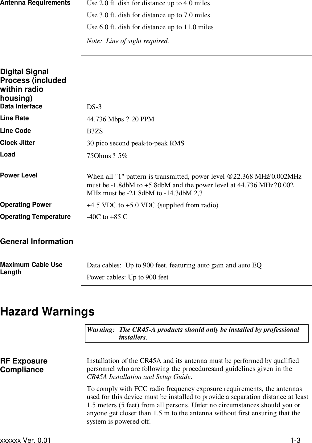
![Troubleshooting xxxx, Ver 0.01 2–2 The CR45-A radio system provides full duplex data communication at full-time 45 Mbps rate, operating in the UNII bands [range needed?]. Under FCC rules, users are not required to be licensed to operate a system, as long as the radio meets the maximum allowable EIRP limits. CR45-A radio has been designed uniquely without a special modulation scheme to provide clear channel. While this radio can manage the transmission of the packet based DS-3 signal, its ability to manage the constant stream of DS-3 signal allows the transportation of most complex signals. Because the radio was designed without complex modulation technology to meet the unlicensed spectrum, data is transported accurately and efficiently. To provide installation ease and minimal maintenance, antenna alignment is the only required procedure. All other adjustments are done automatically. Product Specifications Wireless Digital Transceiver RF system 5.8 GHz Operation Full-duplex Operating Frequency 5.775 GHz TX and 5.301 GHz RX 5.301 GHz TX and 5.775 GHz RX Data Interface Baseband DS-3 Data Modulation Scheme none Connectors 75 ohm female BNC (Data In, Data Out) Type N female (antenna) 4-pin twist lock (DC power) Regulatory Compliance FCC Part 15, Subpart E Operating Temperature Range -40C to +80C Power Requirement 15 VDC to 27 VDC @ 0.85 Amps Operating Range 11 miles Physical Dimensions 7.50 in. wide, 8.5 in. high, 2 in. deep (width includes mounting ears)](https://usermanual.wiki/BitRage-orporated/CR45-A-53.Manual/User-Guide-146912-Page-4.png)
![xxxx, Ver. 0.01 2-1 Section 2 . Troubleshooting Connectors and Indicators The cable connectors and status indicators on the CR45-A are shown in Figure 2-1 and described as follows: [insert illustration here] Figure 2-1. CR45-A Connectors and Indicators ?Antenna connector Type N female 50 Ohm Use up to 3.0 ft cable ? Data In connector BNC female 75 Ohm Use RG 59 cable up to 900 feet Note: Automatic Gain and Automatic EQ circuits are built-in ? Data Out connector BNC female 75 Ohm Use RG 59 cable up to 900 feet Note: Automatic Gain and Automatic EQ circuits are built-in ? Power connector 4-pin female twist lock 2 pins are assigned to receive the DC operating voltage 2 pins are assigned to send the status data signal to the remote monitoring unit ? Numeric display Used during the alignment process. Maximum value is displayed when antenna is in the ideal position. ? RX LED On when data is being received ? TX LED On when data is being transmitted ? Power display On when DC operating power is present in the radio](https://usermanual.wiki/BitRage-orporated/CR45-A-53.Manual/User-Guide-146912-Page-7.png)