BitRage orporated CR45-A-53 Point to Point Fixed UNII Transmitter User Manual CR45ig
BitRage Incorporated Point to Point Fixed UNII Transmitter CR45ig
UserManual.wiki
>
BitRage orporated
>
CR45-A-53 User Manual
>
Install Guide
Contents
1.
Manual
2.
Install Guide
Install Guide
Navigation menu
Upload a User Manual
Namespaces
Wiki Guide
HTML
PDF
Info
Views
User Manual
Discussion / Help
Navigation
![xxxx, Ver. 0.01 1-1 Section 1. Product Description Introduction [BitRage company, introductory info] Symbols Used In This Guide A note (icon1:) within this guide provides supplemental information that may be useful in procedures or may indicate an exception or anomaly. A caution (icon2:) indicates a condition or a risk factor that could disrupt normal operations or create difficulty with data reception or output. A warning (icon3) indicates danger a situation that could cause bodily injury or death. Note: This guide is intended for use by professional installation personnel Before you work on any equipment, be aware of the hazards involved with electrical circuitry and be familiar with standard practices for preventing accidents.. CR45-A Overview [add photograph of CR45-A] Figure 1-1. The CR45-A](https://usermanual.wiki/BitRage-orporated/CR45-A-53.Install-Guide/User-Guide-146942-Page-3.png)
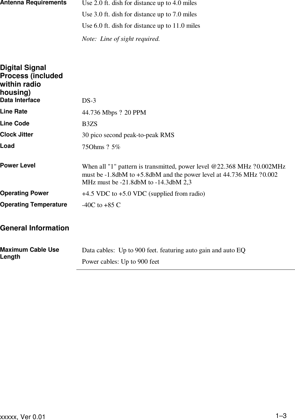
![Product Description xxxx, Ver 0.01 1–2 The CR45-A radio system provides full duplex data communication at full-time 45 Mbps rate, operating in the UNII bands [range needed?]. Under FCC rules, users are not required to be licensed to operate a system, as long as the radio meets the maximum allowable EIRP limits. CR45-A radio has been designed uniquely without a special modulation scheme to provide clear channel. While this radio can manage the transmission of the packet based DS-3 signal, its ability to manage the constant stream of DS-3 signal allows the transportation of most complex signals. Because the radio was designed without complex modulation technology to meet the unlicensed spectrum, data is transported accurately and efficiently. To provide installation ease and minimal maintenance, antenna alignment is the only required procedure. All other adjustments are done automatically. Product Specifications Wireless Digital Transceiver RF system 5.8 GHz Operation Full-duplex Operating Frequency 5.775 GHz TX and 5.301 GHz RX 5.301 GHz TX and 5.775 GHz RX Data Interface Baseband DS-3 Data Modulation Scheme none Connectors 75 ohm female BNC (Data In, Data Out) Type N female (antenna) 4-pin twist lock (DC power) Regulatory Compliance FCC Part 15, Subpart E Operating Temperature Range -40C to +80C Power Requirement 15 VDC to 27 VDC @ 0.85 Amps Operating Range 11 miles Physical Dimensions 7.50 in. wide, 8.5 in. high, 2 in. deep (width includes mounting ears)](https://usermanual.wiki/BitRage-orporated/CR45-A-53.Install-Guide/User-Guide-146942-Page-4.png)
![Product Description xxxx, Ver 0.01 1–4Connectors and Indicators The cable connectors and status indicators on the CR45-A are shown in Figure 1-2 and described as follows: [insert illustration here] Figure 1-2. CR45-A Connectors and Indicators ?Antenna connector Type N female 50 Ohm Use up to 3.0 ft cable ? Data In connector BNC female 75 Ohm Use RG 59 cable up to 900 feet Note: Automatic Gain and Automatic EQ circuits are built-in ? Data Out connector BNC female 75 Ohm Use RG 59 cable up to 900 feet Note: Automatic Gain and Automatic EQ circuits are built-in ? Power connector 4-pin female twist lock 2 pins are assigned to receive the DC operating voltage 2 pins are assigned to send the status data signal to the remote monitoring unit ? Numeric display Used during the alignment process. Maximum value is displayed when antenna is in the ideal position. ? RX LED On when data is being received ? TX LED On when data is being transmitted ? Power display On when DC operating power is present in the radio](https://usermanual.wiki/BitRage-orporated/CR45-A-53.Install-Guide/User-Guide-146942-Page-6.png)
![xxxx, Ver. 0.01 2-1 Section 2 . Installing the Equipment [Overview info] Basic Safety Guidelines The following general guidelines should always be followed when installing or doing maintenance work on any electrical or radio equipment ??Do not locate the transceiver near overhead power lines or other electric light or power circuits, or where it can come into contact with such circuits. ??Never defeat the ground conductor or operate the equipment in the absence of a suitably installed ground conductor. Contact the appropriate electrical inspection authority or an electrician if you are uncertain that a suitable grounding is available. ??Do not work on the system or connect or disconnect cables during periods of lightning activity. ??Disconnect all power and external cables before moving a chassis. ??Do not work alone if potentially hazardous conditions exist. ??Always verify that power has been disconnected from a circuit; never assume it has been. ??Do not perform any action that creates a potential hazard to people or makes the equipment unsafe. ??Carefully examine your work area for possible hazards such as moist floors, ungrounded power extension cables, and missing safety fuses. Warning: This equipment contains an energy hazard. Disconnect the system before servicing.](https://usermanual.wiki/BitRage-orporated/CR45-A-53.Install-Guide/User-Guide-146942-Page-7.png)
![Installing the Equipment xxxxx, Ver 0.01 1–3Additional Responsibilities In addition to meeting these requirements, the antenna system installer is responsible for installing antennas so that they comply with FCC RF exposure requirements. The FCC RF exposure requirements at a given location are based on the sum total of contributions from all radio sources. For BitRage antennas placed in close proximity to other transmitters, installers must ensure that MPE guidelines in 1.1307 of the FCC Rules can still be met, after including the contribution from the new antenna. Further information and guidance is available in FCC Bulletin OET 65, www.fcc.gov/oet/rfsafety. Persons operating the equipment must ensure that it does not cause interference. Specifications must be followed for any special cables (for example, shielded cables) that are required for the unit to meet the EMC standards to which compliance is declared. The user must not make any modifications to the unit, unless expressly approved by the party responsible for compliance. Failure to comply with this rule could void the user's authority to operate the equipment. Installation Checklist [to be added] Installation and Verification Procedures After the antenna dish has been installed, follow these procedures to connect radio: 1. Attach the radio on a permanent position within the reach of the R.F. cable that connects between the radio and antenna. 2. Connect the R.F. cable between the radio and antenna. 3. Route the RX, TX, and POWER cables from the radio to the termination point. 4. Connect the RX, TX, and POWER cables to the radio. 5. Secure the POWER SUPPLY unit at a desired location. Do not connect the AC cable at this time. 6. Connect the RX, TX, and POWER cables to the POWER SUPPLY unit. 7. Connect the I/O data cables between the application device and POWER SUPPLY unit. Application devices must generate and accept the DS-3 specified signals.](https://usermanual.wiki/BitRage-orporated/CR45-A-53.Install-Guide/User-Guide-146942-Page-9.png)