Bittium Wireless DT40ISAP Integrated Service Access Point User Manual ISAP User Guide ENU
Bittium Wireless Ltd. Integrated Service Access Point ISAP User Guide ENU
Contents
- 1. 08 user guide
- 2. 08 user manual
- 3. 08 ISAP User Guide
- 4. 08 User Guide
08 ISAP User Guide

Integrated Service Access Point
Page 1
User Guide
of 30
Copyright © BMW AG / Integrated Service Access Point
Version 1.0/ March 08
Integrated Service Access Point
Product Description
User Guide
Version: 1.0
Date: February 08

Integrated Service Access Point
Page 2
User Guide
of 30
Copyright © BMW AG / Integrated Service Access Point
Version 1.0/ March 08
Table of Contents
1
Introduction................................................................................................................... 4
1.1
Welcome........................................................................................................................................... 4
1.2
Safety notes ..................................................................................................................................... 5
1.2.1
General safety warnings....................................................................................................... 5
1.2.2
Important warnings for use of device.................................................................................. 5
1.3
About this document....................................................................................................................... 6
1.4
Regulatory information.................................................................................................................... 7
1.5
Delivery content............................................................................................................................... 7
2
Technical Data............................................................................................................... 9
3
Components ................................................................................................................ 10
3.1
Access Point ..................................................................................................................................10
3.1.1
LED functions......................................................................................................................11
3.1.2
Antenna connectors ...........................................................................................................12
3.1.3
Reset button........................................................................................................................12
3.1.4
LAN connector....................................................................................................................12
3.1.5
USB connector....................................................................................................................12
3.1.6
AC connector ......................................................................................................................13
3.2
Antennas ........................................................................................................................................13
3.3
Mounting plate and installation kit ...............................................................................................14
3.4
Accessories....................................................................................................................................14
3.4.1
Power cord .......................................................................................................................... 14
3.4.2
LAN cable............................................................................................................................14
4
Unpacking and Installation........................................................................................... 15
4.1
Unpacking instructions.................................................................................................................. 15
4.2
Installation location........................................................................................................................15
4.3
Mounting instructions ...................................................................................................................16
4.3.1
Fixing mounting plate.........................................................................................................17
4.3.2
Placing ISAP on mounting plate........................................................................................18
4.3.3
Connecting cables.............................................................................................................. 20
4.3.4
Removing ISAP from mounting plate................................................................................20
5
Registration, Configuration and Operation .................................................................. 21
5.1
Registration of ISAP ......................................................................................................................21
5.1.1
Automatic registration........................................................................................................ 21
5.1.2
Manual registration.............................................................................................................21
5.2
Configuration and operation .........................................................................................................21
5.2.1
Configuration ......................................................................................................................21
5.2.2
Channel scanning ............................................................................................................... 21
6
Maintenance................................................................................................................ 23
6.1
Status information .........................................................................................................................23
6.2
Cleaning ISAP ................................................................................................................................23
6.3
Cable state .....................................................................................................................................23
6.4
Replacing a defective cable ..........................................................................................................23
6.5
Replacing antennas .......................................................................................................................23
6.6
Reset to factory settings...............................................................................................................24

Integrated Service Access Point
Page 3
User Guide
of 30
Copyright © BMW AG / Integrated Service Access Point
Version 1.0/ March 08
6.7
Replacing ISAP for maintenance purposes................................................................................. 25
7
Troubleshooting .......................................................................................................... 26
8
Terms and Abbreviations............................................................................................. 28
9
References................................................................................................................... 29
10
List of Figures .............................................................................................................. 30
Integrated Service Access Point
Page 4
User Guide
of 30
Copyright © BMW AG / Integrated Service Access Point
Version 1.0/ March 08
1 Introduction
1.1 Welcome
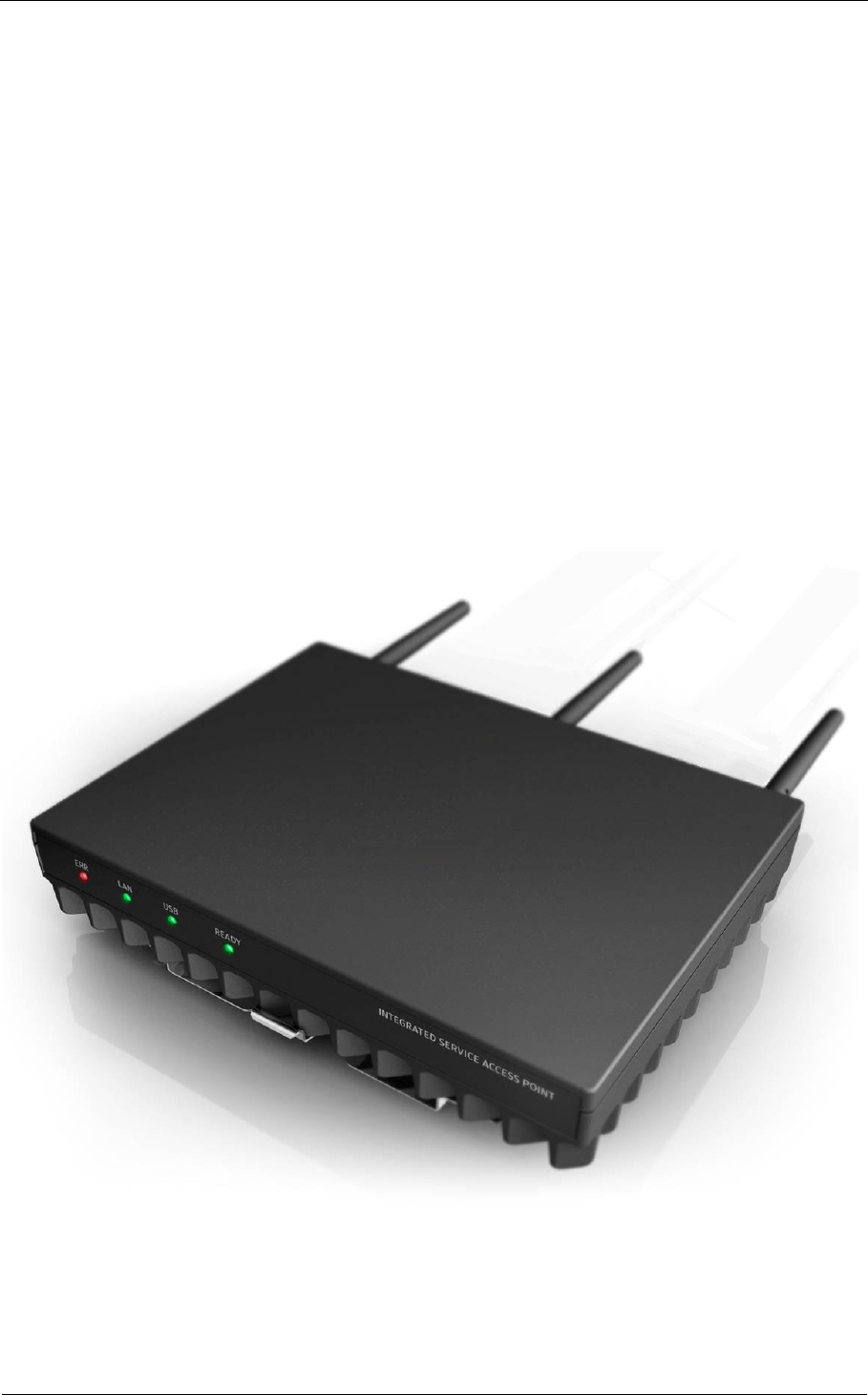
The Integrated Service Access Point (ISAP) is a wireless communication device developed by EB
(Elektrobit Corporation) and optimized for BMW ITOOLS application. The Integrated Service Access
Point is referred as “ISAP” later on in this User Guide.
The ISAP operates at 2.4GHz and 5GHz WLAN band frequencies. It is designed to operate in the
802.11n WLAN mode. The ISAP is a device utilizing latest technologies not necessarily familiar to all
users. Therefore it is strongly recommended that this guide be read through carefully. Before
operating the ISAP, the safety notes described in the following chapters must be understood and
followed.
The main advantages of ISAP are:
• Very high wireless performance compared to older standards (802.11abg)
• Robust design with high reliability
• Easy administration via Workshop System Management (WSM)
• AC power feed
• Diagnostics for wireless traffic
• Supports remote firmware downloads
Figure 1-1: Integrated Service Access Point (ISAP)
Integrated Service Access Point
Page 5
User Guide
of 30
Copyright © BMW AG / Integrated Service Access Point
Version 1.0/ March 08
1.2 Safety notes
This part introduces the different signs that will be used all along this user guide and the important
warnings to remember at all times when using the device.
1.2.1 General safety warnings
Danger!
Means that by not following the instruction there is a possibility of death and/or serious
injury.
Warning!
Means that by not following the instruction there is a possibility of serious injury and/or
damage in ISAP and/or surrounded materials.
Attention!
Means that not following the instruction can cause damages to the device or data.
Info!
Tips and hints for easier operation.
1.2.2 Important warnings for use of device
Please pay careful attention to the following remarks.
Danger!
Do not use damaged equipment and/or accessories such as damaged power cord.
Danger!
Do not use any other accessories than those provided with the device. The use of any
other parts will cause danger and void the warranty.
Danger!
Never try to open the device. By trying to open the device you will be exposed to a risk
of death or injury.
Danger!
Do not use this product during thunderstorm, floods and other dangerous climate
events susceptible to cause serious harm to persons.
Danger!
Never operate ISAP near open fuel tanks. There is a risk of fire or explosion.
Warning!
Read this user guide carefully before mounting, installing and operating the device.
Warning!
Do not use extension cord for power cable, use only the power cable delivered with the
device.
i

Integrated Service Access Point
Page 6
User Guide
of 30
Copyright © BMW AG / Integrated Service Access Point
Version 1.0/ March 08
Warning!
Never unplug equipment from the electrical outlet by holding the cord only, always
disconnect the cable by applying force directly to the plug.
Warning!
Ensure sufficient air cooling when installing ISAP.
Warning!
Do not apply any forces with any tools to the antenna connectors’ threads when
connecting or disconnection the antennas. The antennas shall be connected and fixed
by hand only.
Warning!
Do not operate the device in any other environmental conditions than it is designed for.
Warning!
Do not open the housing of the ISAP. There are no serviceable parts inside!
1.3 About this document
This document provides instructions regarding the installation, the set up and the operation of the
device.
• Chapter one gives general information regarding the product safety and legal notifications. It
is very important that this chapter is read carefully before operating ISAP.
• Chapter two provides information on technical details and environmental restrictions of the
access point.
• Chapter three describes in detail the components delivered with the ISAP.
• Chapter four presents all needed steps in order to install the access point.
• Chapter five gives hints on registration, configuration and operation of the ISAP.
• Chapter six covers maintenance.
• Chapter seven is a troubleshooting guide in case of unexpected behavior.
Integrated Service Access Point
Page 7
User Guide
of 30
Copyright © BMW AG / Integrated Service Access Point
Version 1.0/ March 08
1.4 Regulatory information
Regulatory Information
Product Name:
ISAP
Product Type:
IP40 version
Further Description: As described in this document
meets the requirements for EMC and Electrical Safety according to
CE-Directives 1999/5/EC, Radio and Telecommunications Terminal Equipment (R&TTE)
2004/108/EC, Electromagnetic Compatibility (EMC)
2006/95/EC, Low Voltage Directive (LVD)
2002/95/EC, Restriction of Hazardous Substances Directive (RoHS)
2002/96/EC, Waste Electrical and Electronic Equipment (WEEE), Note 1)
UL listed E319085
Note 1) Waste Electrical and Electronic Equipment (WEEE) Directive 2002/96/EC
This product complies with the WEEE Directive (2002/96/EC) marking
requirements. The affixed product label (see beside) indicates that you must not
discard this electronic product in domestic household waste. This mark on the
product, the packaging or the relevant documentation indicates that this product
may not be treated as ordinary household garbage. Please contact first level support
on how to organize disposal at your country.
FCC Statement: This equipment has been tested and found to comply with the limits for a Class B
digital device, pursuant to Part 15 of the FCC Rules. These limits are designed to provide reasonable
protection against harmful interference in a residential installation. This equipment generates, uses
and can radiate radio frequency energy and, if not installed and used in accordance with the
instructions, may cause harmful interference to radio communications. However, there is no
guarantee that interference will not occur in a particular installation. If this equipment does cause
harmful interference to radio or television reception, which can be determined by turning the
equipment off and on, the user is encouraged to try to correct the interference by one or more of the
following measures:
• Reorient or relocate the receiving antenna.
• Increase the separation between the equipment and receiver.
• Connect the equipment into an outlet on a circuit different from that to which the receiver is
connected.
• Consult the dealer or an experienced radio/TV technician for help.
This device complies with Part 15 of the FCC Rules and with RSS-210 of Industry Canada. Operation
is subject to the following two conditions:
(1) This device may not cause harmful interference, and
(2) This device must accept any interference received, including interference that may cause
undesired operation.
This Class B digital apparatus complies with Canadian ICES-003.
Cet appareil numérique de la classe B est conforme à la norme NMB-003 du Canada.
Integrated Service Access Point
Page 8
User Guide
of 30
Copyright © BMW AG / Integrated Service Access Point
Version 1.0/ March 08
Warning!
Changes or modifications made to this equipment not expressly approved by
manufacturer may void the authorization to operate this equipment.
1.5 Delivery content
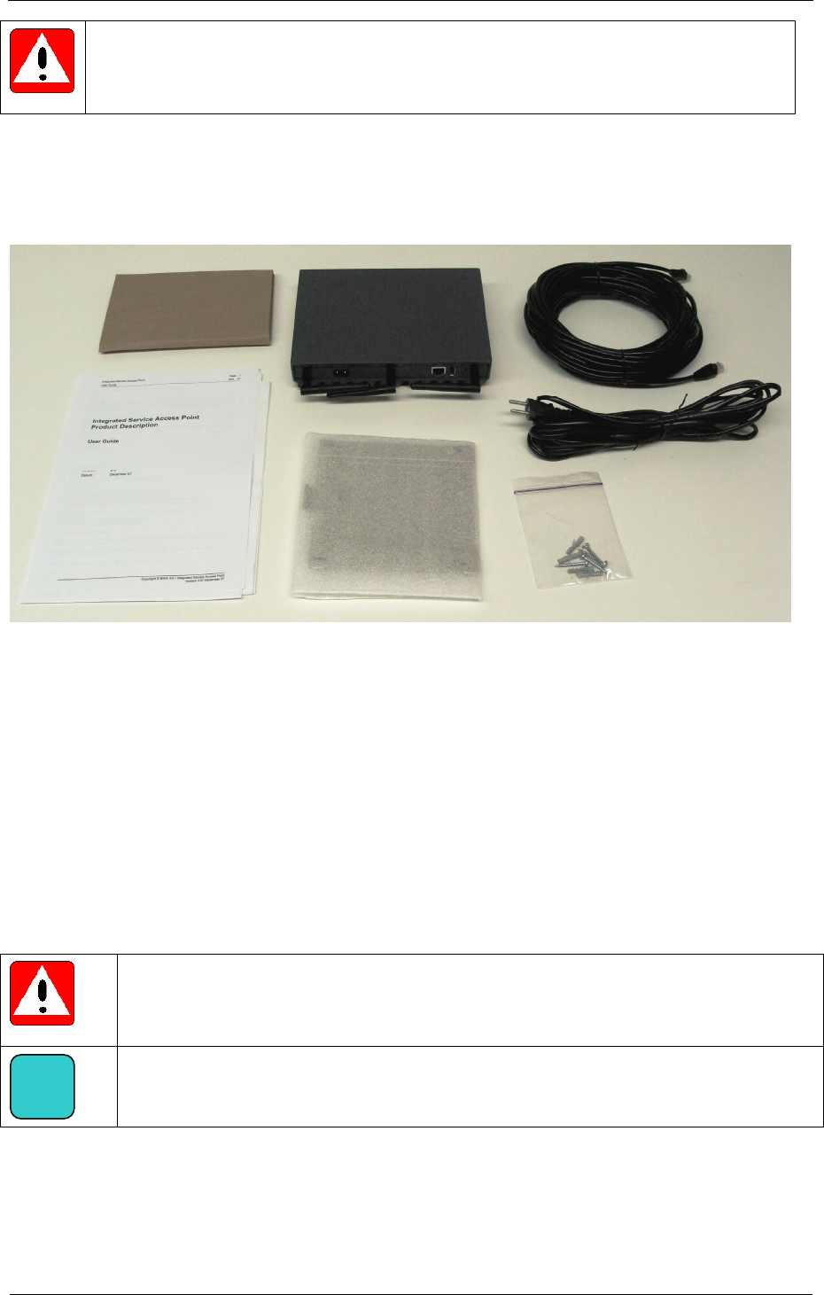
It is highly recommended that the package content be checked immediately after receiving it. The
package contains the following items:
Figure 1-2: Delivery content
1. ISAP with attached Antennas
2. 20m Ethernet cable (Cat5e)
3. 4.5m power cable (country specific)
4. Printed documentation and certificates
5. Documentation CD
6. Mounting plate
7. Wall mounting kit
Attention!
If any of the parts listed above is missing or damaged, please contact first level help
desk immediately.
Info!
Read section 2 & 3 for further technical details about ISAP components
i
5
4
2
3
6 7
1

Integrated Service Access Point
Page 9
User Guide
of 30
Copyright © BMW AG / Integrated Service Access Point
Version 1.0/ March 08
2 Technical Data
Name
Integrated Service Access Point, ISAP
Functionality
Wireless communication device for industrial applications
Physical dimensions
Approximately 220 x 170 x 36 mm, without antennas
Weight
Approximately 1.5 kg
Environmental protection
IP40
Operating temperature range
-10...+50 °C
Operating altitude range
0…3048 m
Power feed
100…240 VAC, 50…60 Hz, 0.2A max., class II (reinforced insulation)
Wireless standards supported
IEEE 802.11b, 802.11g, 802.11a, 802.11n Draft 2
Frequency range
2.400..2.4835 GHz
5.150..5.350 GHz, 5.470..5.725 GHz, 5.725..5.825 GHz
Occupied channel bandwidth
According to the IEEE 802.11n Draft 2
Data rates supported
802.11b: 1Mbit/s, 2, 5.5 & 11Mbit/s
802.11g & 802.11a: 6Mbit/s, 9, 12, 18, 24, 36, 48 & 54 Mbit/s
802.11n 20MHz BW: 1 Nss: 65(72.2)Mbps max.
2 Nss: 130(144.444)Mbit/s max.
802.11n 40MHz BW: 1 Nss: 135(150)Mbit/s max.
2 Nss: 270(300)Mbit/s max.
RF transmission power (ERP)
+5...+18 dBm, Settable in 1 dB steps
RF antenna interfaces
Three Antennas, MIMO
Receiver sensitivity in
specified operating
temperature range
802.11b: -92 dBm (1 Mbit/s), -89, -86, -84 dBm (11 Mbit/s)
802.11g: -90 dBm (6 Mbit/s), -88, -86, -84,
-81, -78,-73, -70 dBm (54 Mbit/s)
802.11a: -90 dBm (6 Mbit/s), -88, -86, -84,
-81, -78, -73, -70 dBm (54 Mbit/s)
802.11n: HT20 -68.8 dBm (300 Mbit/s), HT40 -65.8 (300 Mbit/s)
Security
WEP, WPA, WPA2, 802.1x, EAP-(T)TLS
Ethernet interface
802.3ab, 10/100/1000 Base-T
Ethernet routing / networking
DHCP Client, NAT Router, VLAN Support, Multi BSSID, Roaming
SSH server, NTP client
USB interface
USB 2.0
Device management
HTTP- with user authentication, remote update for device settin
g
s
and firmware
CLI (Command Line Interface) throu
g
h SSH session
Connectors
RF Antenna Connectors: 3* SMA-RP
Ethernet Connector: RJ45
Power Feed: IEC-C8
LED indicators
READY, LAN, USB, ERR
Performance
Up to 150 Mbit/s TCP pa
y
load throu
g
hput
Technical platform
Processor: Atheros AR7161
Wireless LAN : Atheros AR9160, AR9106
Memories : 512Mb SDRAM, 64Mb FLASH
LAN interface: Based on Marvell Alaska 88E1111 Phy transceiver
Certificates
UL E314312, CE, CB-Report
For other national approvals, see certification list
Important Note
National restrictions on frequencies, power levels and operatin
g
modes ma
y
appl
y
Integrated Service Access Point
Page 10
User Guide
of 30
Copyright © BMW AG / Integrated Service Access Point
Version 1.0/ March 08
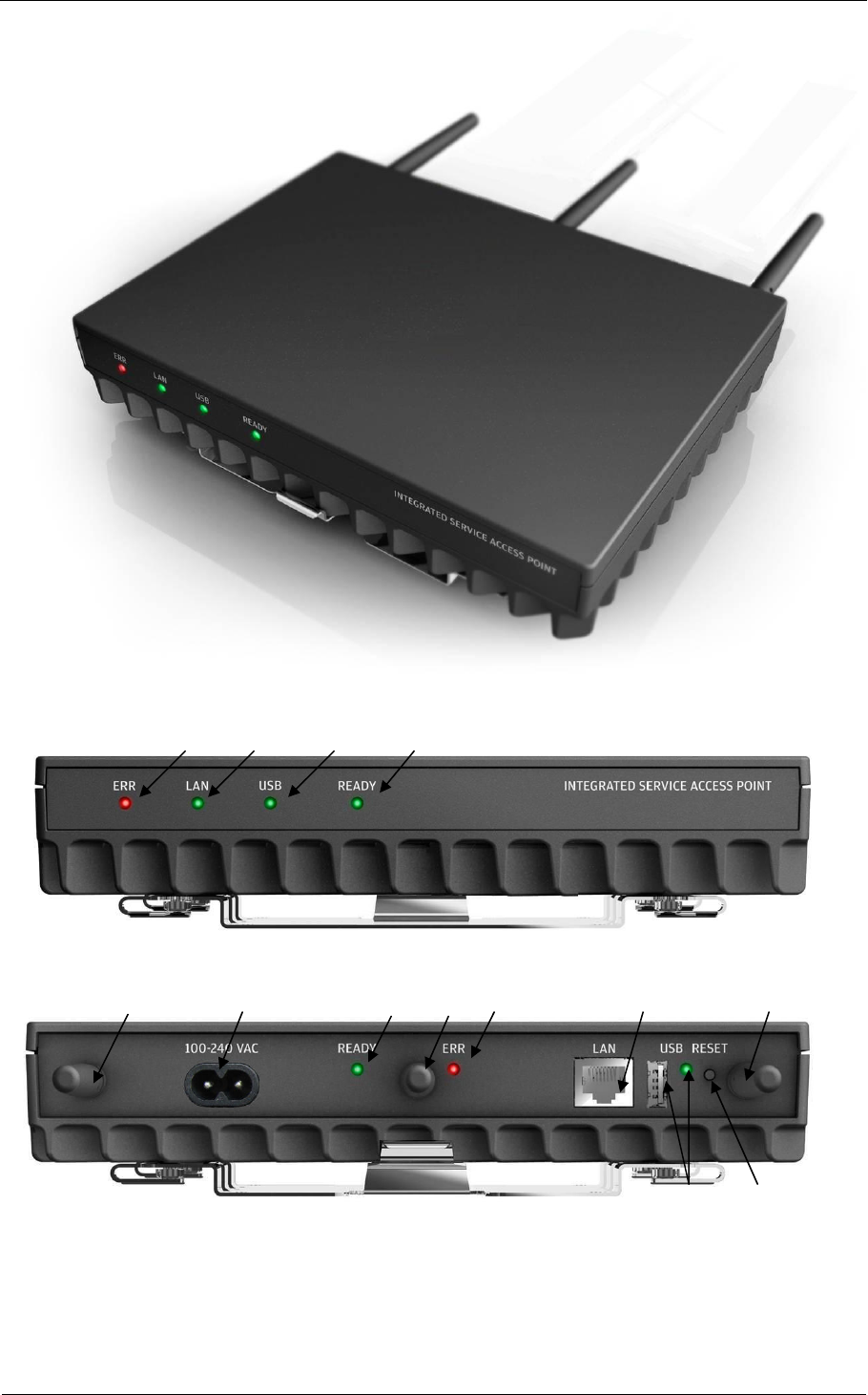
3 Components
3.1 Access Point
Figure 3-1: Integrated Service Access Point
Figure 3-2: ISAP front view and markings
Figure 3-3: ISAP connectors’ side and markings
Description of connectors and LEDs:
1. ERR LED 5. RESET switch
2. LAN LED 6. AC connector
3. USB connector and LED 7. LAN connector
4. READY LED 8. Antenna connectors
4 3 1 2
6
8 4 8 1
7
2
3 5
8

Integrated Service Access Point
Page 11
User Guide
of 30
Copyright © BMW AG / Integrated Service Access Point
Version 1.0/ March 08
3.1.1 LED functions
Four LEDs are located on both side of the device, on the front side and on the connectors’ side. Note
that the LAN led at the connectors’ side is integrated into the LAN connector.
Start-up: note that there are three kinds of errors indicated during start-up:
a) The LAN connection is broken or not connected: the LAN led will remain unlit.
b) The registration of ISAP with Workshop System Management (WSM) has not been able to
start: the READY led will stay yellow, which should alert the user.
c) The registration of ISAP with Workshop System Management (WSM) started, but a problem
occurred during the connection to WSM: the YELLOW READY led will blink, which should
alert the user to check the status of Workshop System Management (WSM).
Table 3-1: LED names and functions
LED Name Status of LED Description Trigger
No light: the ISAP is not
powered
Yellow: the ISAP is switched
on and the power up process
is ongoing
Power applied, power cable
connected to AC feed
Yellow flashing: the
registration on Workshop
System Management (WSM)
is ongoing
ISAP Registration process
started
Green: the ISAP is operational Device powered, LAN active,
ISAP registered and WLAN
activated
READY
Green flashing: the firmware
upgrade procedure is ongoing
Upgrade process started
No light: LAN is not
operational
LAN
Green: LAN is linked up Ethernet cable physically and
successfully connected to ISAP
No light: no USB device
connected
USB
Green light: USB device
connected
USB device connected to ISAP
No light: no errors detected Built-in self-test (BIST) passed
successfully
ERR
Red: an error or warning is
pending, details are available
in WSM
BIST failed due to high
temperature, voltage warning or
services down
Integrated Service Access Point
Page 12
User Guide
of 30
Copyright © BMW AG / Integrated Service Access Point
Version 1.0/ March 08
3.1.2 Antenna connectors
The ISAP has three sub-miniature version A (SMA) male reverse-polarity antenna connectors for
three external antennas. All three antennas must be connected for correct ISAP operation and
performance. The antennas need to be properly attached.
Warning!
No dust or dirt should get into the connectors.
Info!
It is highly recommended to keep the antennas connected in all situations, as they will
provide needed protection against dust and dirt.
Info!
The ISAP is delivered with mounted antennas. The user would need to replace the
antennas only for maintenance purpose when necessary.
Warning!
Do not apply any forces with any tools to the antenna connectors’ threads when
connecting or disconnection the antennas. The antennas shall be connected and fixed
by hand only.
3.1.3 Reset button
The reset button is a push button, which allows user to reset the ISAP configuration to factory
settings. Resetting the configuration factory parameters is necessary when moving the ISAP to a new
location, or for ITOOLS fault analysis and recovery purposes of ISAP maintenance. Please refer to
chapter 5.6 for details on how to restore the factory settings by using reset button.
Info!
Please reset ISAP only if first level support instructs you to do so. There will be
additional steps to be done by you in order to transfer ISAP configuration from server
ISIS each time you reset ISAP.
3.1.4 LAN connector
ISAP utilizes Ethernet networking topology to connect to the backbone. The connector is RJ45 type
and enables 10/100/1000 Mbit connections. The LAN connector LED will lit green in order to indicate
connection of LAN cable.
3.1.5 USB connector
There is one Type A USB connector located on the ISAP connector panel (see Figure 3-3).
The USB connector is planned to be used for connecting ITOOLS extension to the infrastructure. The
USB connector’s protecting rubber cover should be kept on unless the USB connector is connected
to ITOOLS extension equipment. This prevents dust and dirt to get into the connector.
Warning!
The USB connector shall not be used for anything else than specified ITOOLS
extension devices. Details will be provided by BMW AG as soon as they will be
available.
i
i
i
Integrated Service Access Point
Page 13
User Guide
of 30
Copyright © BMW AG / Integrated Service Access Point
Version 1.0/ March 08
3.1.6 AC connector
The connector used for ISAP is an IEC60320-C8 power plug. The power supply module is integrated
into the ISAP and can be connected to mains voltages of 100…240 VAC, 50…60Hz with the power
cable provided.
Danger!
Do not use any other power cord than the one delivered with the device. The use of any
other cord will cause danger and void the warranty.
Warning!
Do not use extension cord for power cable, use only the power cable delivered with the
device.
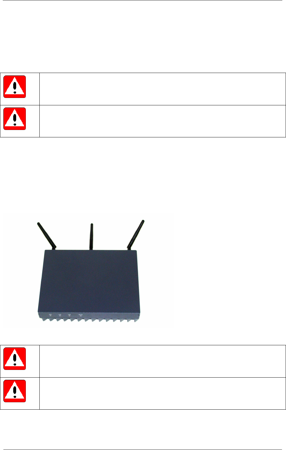
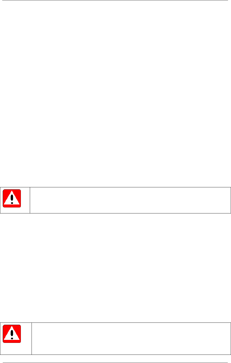
3.2 Antennas
ISAP includes external WLAN Tri-band small diameter antennas, which cover frequencies from 2.4 to
6 GHz. Omni-directional patterns with gain in upper frequencies give optimal coverage for workshop
environment. The antenna has a gain of 2.1 dBi at 2.45 GHz and 2.5 dBi at 5.875 GHz. The antennas
should be placed so that they are pointing all into different directions. The performance of ISAP is
maximized when antennas create as different (i.e. non-correlating) spatial streams as possible. See
Figure 3-4 below for example how to point antennas.
Figure 3-4: Example of antenna directions
Warning!
Do not push the antennas to the angles which the flexible joint doesn’t easily allow.
Otherwise you might break the joints.
Warning!
Use only the antennas which are delivered with the device – changes to antenna
configuration void operating permission and certificates.
Integrated Service Access Point
Page 14
User Guide
of 30
Copyright © BMW AG / Integrated Service Access Point
Version 1.0/ March 08
3.3 Mounting plate and installation kit
A metal mounting plate is delivered with the ISAP. It enables mounting the ISAP vertically on a wall,
made from concrete. Always use the delivered mounting plate for fixing the ISAP. It is designed to
enable efficient cooling of the ISAP and proper mounting and holding. The installation kit includes the
required screws and dowels for fixing the mounting plate on the wall.
3.4 Accessories
3.4.1 Power cord
A 4.5 meter long power cord is delivered with the ISAP, with improved resistance to media normally
found in the workshop environment. Depending on the AC wall adapters used in each country, one or
more of the cables is supplied with each ISAP
Danger!
Do not use any other power cord than the one provided with the device. The use of any
other cord will result in danger and void the warranty. In some countries using a
different power cord than the one supplied may also void ISAP type approvals.
Warning!
Do not use any extension cord, use only the power cable delivered with the device.
Warning!
Never unplug equipment from the electrical outlet by holding the cord only, always
disconnect the cord by applying force directly to the plug.
3.4.2 LAN cable
A 20 meter long LAN cable is delivered with the ISAP. This is a Cat5e shielded cable with RJ45
connectors on both ends.
Warning!
Do not use any extension cables, use only the LAN cable delivered with the device. In
some countries using a different LAN cable than the one supplied may also void ISAP
type approvals.

Integrated Service Access Point
Page 15
User Guide
of 30
Copyright © BMW AG / Integrated Service Access Point
Version 1.0/ March 08
4 Unpacking and Installation
Warning!
Only installation by a professional is allowed.
4.1 Unpacking instructions
The ISAP delivery box is made of carton which can be recycled through standard process used for
carton materials. However, the box has been approved with logistical experts and should be kept in
safe in case there will be need to send ISAP back to another location or to repair.
The content is packed in two separate spaces. The ISAP main device is packed directly inside the
package with two carton parts which hold it in correct place. The other material can be found from the
internal carton box below ISAP main device.
1. Open and remove the first outside cover carton box
2. Open the second cover carton box and lift up the ISAP main device
3. Open the internal box which include all the other delivery content
4. Check that the delivery content is according to chapter 0
4.2 Installation location
If there were no problems with previous the Access Point in Workshop, it is a good idea to consider
mounting the ISAP to the place where the previous generation Access Point has been mounted
before. For best performance the following notes should be considered and mounting locations
should be selected based on given hints:
1. The mounting location should be selected so that it is central for assumed ITOOLS
operations:
o Mount the ISAP near to the place where wireless networks will be mostly used
o Allow a line of sight contact between the ISAP and the workplace where ITOOLS will
be used
o Installing ISAP high on the wall typically allows best radio coverage and optimum
operation, minimum height of 2 meters is recommended
2. Select the mounting location so that it is free from unnecessary obstacles, or removing
obstacles nearby ISAP installation location
o Obstacles, such as metal surfaces in desks, filing cabinets, bookshelves, and
wastebaskets close to the ISAP may degrade the performance
3. Mounting location distance from the Workshop LAN backbone (ISIS)
o ISAP is connected to ISIS backbone with a 20 meters Ethernet cable
o ISAP mounting point shall be selected so that the supplied 20 meters cable can
connect the ISAP to the ISIS backbone without any cable extension. The Ethernet
connection cable should be installed and fixed in a way that cable does not cause
Integrated Service Access Point
Page 16
User Guide
of 30
Copyright © BMW AG / Integrated Service Access Point
Version 1.0/ March 08
problems for workshop operations. The cable should be fixed at a safe distance from
any moving tools, vehicles, etc. In order to connect the ISAP to the ISIS, please use
the ISIS Gigabit switch or Layer-2-switch. If you use a router instead, make sure that
it is configured correctly. For detailed information please refer to the special
information on workshop cabling and installation provided by your market.
o Observe local regulations regarding cable installation!
4. The distance to other operational wireless networks should be maximized.
5. Interference from other wireless networks may be eliminated or reduced by:
o Changing the channel of ISAP operation by using Workshop System Management
(WSM) or changing the operational channels of surrounding wireless networks. You
should consider using the built-in Channel Scanning feature of the ISAP. This feature
will help you to detect other wireless networks in surrounding environment and will
help you to select an appropriate channel to minimize disturbances and interferences
from other transmitters. Please refer to Chapter 5.2 for more details on Channel
Scanning.
o Adjusting the power levels of other wireless networks nearby. Please check with your
IT responsible person on the preconditions of WLAN operation.
4.3 Mounting instructions
Warning!
Do not use any other mounting equipment than those provided with the device. Using
other mounting equipment may cause damage to the device, personnel or surrounding
environment.
Warning!
The total weight of the ISAP is almost 2 kg. The wall must be made from appropriate
material to be able to handle the weight of the ISAP through the four mounting screws.
Integrated Service Access Point
Page 17
User Guide
of 30
Copyright © BMW AG / Integrated Service Access Point
Version 1.0/ March 08
4.3.1 Fixing mounting plate
Before fixing the mounting plate, ensure that there are no electrical lines or water lines in the wall at
that location.
• ISAP mounting plate is fixed with
4 screws, delivered as part of ISAP
fixing kit
• ISAP can be mounted on a wall
made from concrete or stone
• Using the delivered plastic dowels
is mandatory
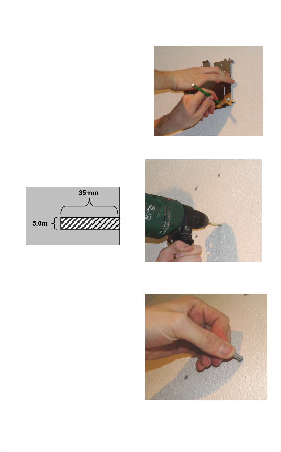
1. Mark the holes placement with the
help of mounting plate, as illustrated in
Figure 4-1. Note the installation
direction.
Figure 4-1: Example of hole marking
2. Drill four 5 mm diameter and 35 mm
deep holes in to the wall, as illustrated
in Figure 4-2
Figure 4-2: Drilling holes
3. Insert the 4 dowels into the holes.
Figure 4-3: Inserting dowels
Integrated Service Access Point
Page 18
User Guide
of 30
Copyright © BMW AG / Integrated Service Access Point
Version 1.0/ March 08
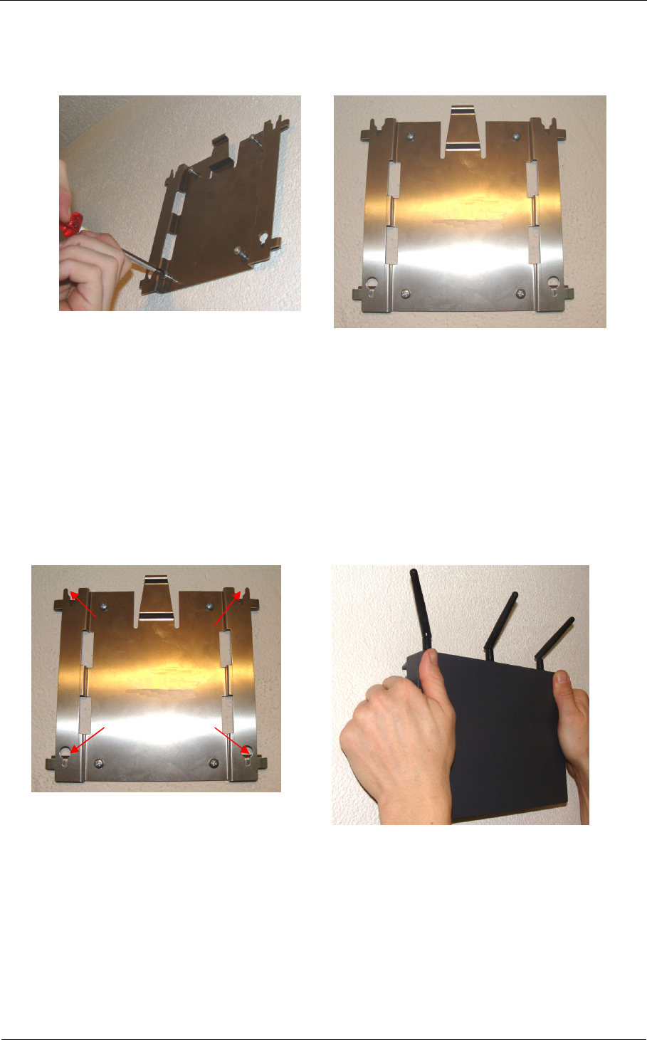
4. Fix the mounting plate with four screws as in Figure 4-4. The locking mechanism must point
upwards as in Figure 4-5.
Figure 4-4: Fixing the plate
Figure 4-5: Example of finished fixed plate
4.3.2 Placing ISAP on mounting plate
1. Place the ISAP on the mounting plate. The screws at the cooling fins of the ISAP should go
into the openings on the mounting plate, see Figure 4-6 below. Place the ISAP horizontally,
antennas must point up, like in Figure 4-7.
Figure 4-6: Openings for ISAP
Figure 4-7: Placing on ISAP horizontally
Integrated Service Access Point
Page 19
User Guide
of 30
Copyright © BMW AG / Integrated Service Access Point
Version 1.0/ March 08
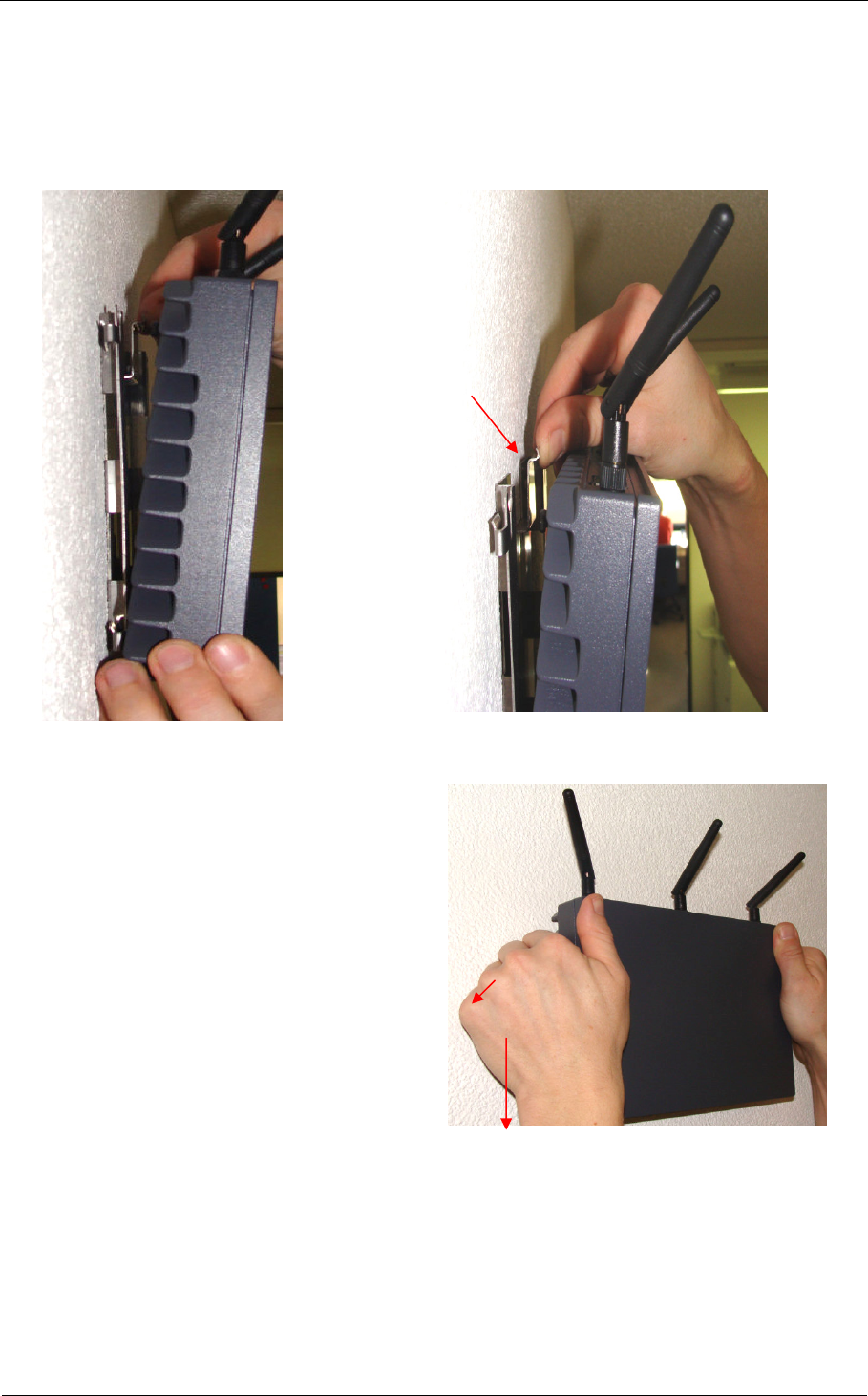
2. Place the ISAP first from below, Figure 4-8. The ISAP will be locked by the locking
mechanism (Figure 4-9) at the mounting plate .
Figure 4-8: Place on first from below
Figure 4-9: Locking mechanism
3. Push the entire ISAP towards the wall
so that the locking mechanism in the
mounting plate moves backwards,
allowing the ISAP to reach also the
upper openings of the mounting plate.
Simultaneously push the ISAP to the
wall and tire down until the locking
mechanism locks clicks and locks the
ISAP. Figure 4-10.
Figure 4-10: Pushing and locking
Integrated Service Access Point
Page 20
User Guide
of 30
Copyright © BMW AG / Integrated Service Access Point
Version 1.0/ March 08
4. Try to lift the ISAP upwards and make
sure that the locking mechanism is
fully visible, and the ISAP has gone
under the locking edge. Figure 4-11.
Figure 4-11: Example of fixed plate
4.3.3 Connecting cables
1. Fix the power cable and LAN cables
on the wall and connect into the ISAP.
Do not leave cables hanging, but
make proper fixings into the wall or
ceiling. Set the antennas like in the
Figure 4-12.
Figure 4-12: Example of fixed ISAP
4.3.4 Removing ISAP from mounting plate
In order to remove ISAP from Mounting plate e.g.
for maintenance reason, do the following:
1. Disconnect all cables
2. Push the locking mechanism inside, see
Figure 4-13
3. Simultaneously lift the ISAP upwards
until it releases itself from the mounting
plate
Figure 4-13: Unlocking ISAP

Integrated Service Access Point
Page 21
User Guide
of 30
Copyright © BMW AG / Integrated Service Access Point
Version 1.0/ March 08
5 Registration, Configuration and Operation
5.1 Registration of ISAP
Every ISAP must be registered before the wireless operation is possible. This chapter provides an
overview of ISAP registration.
5.1.1 Automatic registration
Most of the workshops have live connection to BMW AG backend systems. In this normal use case,
the registration of the ISAP is done automatically through Workshop System Management (WSM)
within the first start-up. For further information please refer to the WSM User Guide [1].
5.1.2 Manual registration
In case the workshop does not have a live connection to the workshop database, the registration of
ISAP must be done manually through a registration fax. For further information please refer to the
WSM User Guide [1].
5.2 Configuration and operation
5.2.1 Configuration
The ISAP is configured through Workshop System Management (WSM) software. Please refer to the
WSM User Guide [1] for details on how to configure the ISAP.
5.2.2 Channel scanning
In the workshops there might be no professional site survey available during initial ITOOLS
installation. Therefore the existing other WLAN band activities and users are not necessary known. In
many cases this is not assumed to be a problem, as workshop is normally relatively well controlled
environment. Additional to the disturbances from the workshop there can potentially be other WLAN
Networks from uncontrollable environments close to the workshop, i.e. from other companies. These
devices might be causing disturbances to ITOOLS Wireless Network operation.
Due to these issues it is highly beneficial that ITOOLS operation is adjusted based on the
environment radio operating conditions. Optimally selected radio frequency channel will improve the
ITOOLS operation quality, performance, and service availability.
Channel Scanning introduces a possibility to analyze the installation environment for potential
problems during configuration and also later on- one of causes for problems is the use of shared radio
channels, and the fact that other surrounding networks may change they operation without notifying
for ITOOLS administration. For this reason ISAP is able to provide information about channel
allocation.
Channel Scanning can be activated through Workshop System Management (WSM), in order to get
the channel scan information from ISAP.
Info!
In Workshop System Management (WSM) channel scanning is referred to as the
Channel Wizard. It can be started via the Device Details tab in WSM.
Caution!
Normal operation of the ISAP is deactivated for the channel scan.
i

Integrated Service Access Point
Page 22
User Guide
of 30
Copyright © BMW AG / Integrated Service Access Point
Version 1.0/ March 08
The Channel Scan operation is based on reporting all Radio Frequency (RF) signal strength values for
the least used channels, taking into account the other surrounding networks. As a result channel scan
will deliver one recommended channel in 2.4 GHz band as well as one recommended channel in the 5
GHz band. It will also deliver some least used channels for each of the two bands. For more details on
using channel scanning please refer to the WSM User Guide [1].
Integrated Service Access Point
Page 23
User Guide
of 30
Copyright © BMW AG / Integrated Service Access Point
Version 1.0/ March 08
6 Maintenance
6.1 Status information
The status information of the ISAP can be seen in the Workshop System Management (WSM)
graphical user interface. More information about the queries of the ISAP status is available in the
WSM User Guide [1].
6.2 Cleaning ISAP
The ISAP is not designed to be in direct contact with dust, dirt or other generally harmful substances.
The media found in workshops, such as oils, acids and cleaners are especially dangerous when
applied directly to the ISAP. In addition, the vapors of such substances are harmful, an adequate air
circulation is recommended. Due to these restrictions, it is highly recommended that the ISAP and
the nearby environment of the ISAP are kept clean of substances mentioned above.
Use only a moist cloth to clean the device. Do not use petroleum based substances or solvents as this
may cause corrosion of the surface of the ISAP.
6.3 Cable state
There are two cables delivered with the ISAP: the LAN cable and the power cable. It is recommended
that the user periodically check the condition of these cables. A simple visual check is adequate. The
cable shall not have any visible cut or scratches. If any damage is visible, the broken cable must be
replaced with a new one.
Danger!
Be careful when checking the power cable. The cable must be disconnected from the
power outlet prior to the checking to avoid the risk of an electric shock.
6.4 Replacing a defective cable
Replacement parts can be ordered through the first level helpdesk. Disconnect the ISAP from power
outlet before replacing a defective cable.
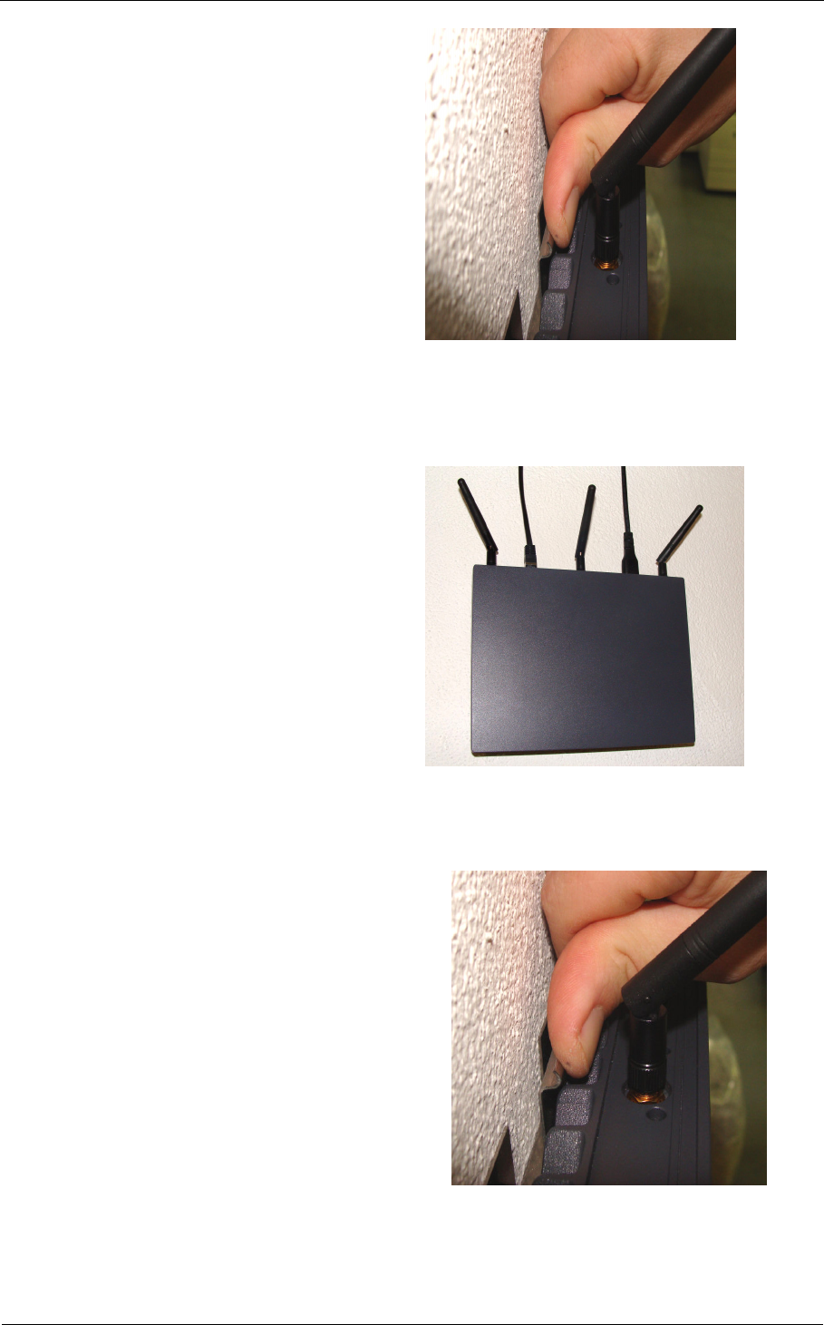
6.5 Replacing antennas
The antennas might be replaced for maintenance purposes. The replacement of the antennas might
be ordered through first level helpdesk. To replace an antenna, proceed with the following steps:
1. Unplug the ISAP power cable
2. Unscrew the antenna(s)
3. Attach the new antenna(s) by hand
Warning!
Do not use any tools when attaching or detaching antennas. Applying an excessively
high momentum force may destroy the connectors. Fixing the antennas by hand is
sufficient.
Integrated Service Access Point
Page 24
User Guide
of 30
Copyright © BMW AG / Integrated Service Access Point
Version 1.0/ March 08
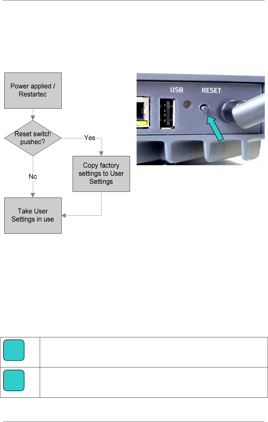
6.6 Reset to factory settings
A reset to factory settings can be issued by the user with external hardware operation as described
below. The user configuration file will be overwritten with the factory default values. A new
configuration with Workshop System Management (WSM) will be necessary. Please refer to the
WSM User Guide [1] for more information about the configuration of ISAP. Please reset the ISAP only
if first level supports tells you to do so.
Figure 6-1: Reset to factory settings
Figure 6-2: Reset button
Follow these steps to reset the ISAP to the factory settings:
1.
Preferred: unplug the power cable, wait 5 seconds, reattach the power cable.
Alternative: if the ISAP is operational, push the reset button (see Figure 6-2) for at least
2 seconds, this will also reboot the ISAP.
2. Push the Reset button (see Figure 6-2) again and hold it down approximately 40 seconds
until ALL the LEDs of the ISAP flash several times.
3. The flashing of all LEDs indicates that the ISAP is set back to factory settings. Release the
reset button now.
Info!
After resetting to factory settings, the ISAP must be configured initially again through
Workshop System Management (WSM).
Info!
In case the READY LED did not switch over to constant yellow, the reset to factory
settings has failed; please try again.
i
i

Integrated Service Access Point
Page 25
User Guide
of 30
Copyright © BMW AG / Integrated Service Access Point
Version 1.0/ March 08
6.7 Replacing ISAP for maintenance purposes
• Remove the defective ISAP as described in chapter 4.3.4.
• Install the new ISAP device as described in chapters 4.3.2 and 4.3.3.
• In case you plan to use same location for reinstalling ISAP, you may leave the mounting plate
installed on the wall.

Integrated Service Access Point
Page 26
User Guide
of 30
Copyright © BMW AG / Integrated Service Access Point
Version 1.0/ March 08
7 Troubleshooting
Warning!
Do not open the housing of the ISAP. There are no serviceable parts inside!
Problem description Solution
Nothing happens even when
the power cord is connected.
Please check that the power outlet connection has 100…240VAC
connected and that all fuses / circuit breakers are intact.
The READY led stays YELLOW
after startup for a very long
time.
Is the LAN led green?
If not, then check the LAN cable connection.
If yes, then wait 10 minutes, if READY led doesn’t start flashing or
turns to green, contact first level support.
Note: When started in cold temperatures, it is normal that the start-
up procedure takes longer.
The READY LED is flashing
yellow for a very long time.
There is problem with the registration process to WSM, please
check the LAN connection and the check the status of WSM.
The wireless network is no
longer functional.
Check the status of the ISAP from the WSM User Interface. Reboot
the ISAP by disconnecting and reconnecting the power cord.
Check the status of other ITOOLS. Is their wireless communication
functional?
The wireless network
connection is not stable.
Try and run the Channel Wizard at WSM to optimize the used
channel.
ERR LED is on There is a problem in ISAP, please check ISAP Status from WSM
user interface, see WSM User Guide [1]
READY LED is flashing green. ISAP is performing a Firmware update, do not disconnect the
power because ISAP will restart itself after update is finished
ISAP is not responding Please check the ISAP status from the WSM user interface, see
WSM User Guide [1]. Is radar detected? If not please try rebooting
the ISAP by reattaching the power cable. If the problem is not
solved please contact support.
“Temperature warning” at
WSM ISAP Status
Check operating conditions of ISAP. Make sure that the ambient
temperature around ISAP is not exceeding +50 °C. Contact support
if the warning doesn’t disappear.
“Services not running” at WSM
ISAP Status
Please reboot ISAP, by re-attaching the power cable. Check that all
services at WSM are running, see WSM User Guide [1]. Contact
support in case the warning doesn’t disappear.
“Hardware failure” at WSM
ISAP Status
Please contact support.
“Interface problem” at WSM
ISAP Status
Check validity of ISAP settings in WSM user interface, see WSM
User Guide [1].

Integrated Service Access Point
Page 27
User Guide
of 30
Copyright © BMW AG / Integrated Service Access Point
Version 1.0/ March 08
“Radar detected” at WSM
ISAP Status
You are using the 5GHz band, radar has been detected and
selection of new channel is ongoing. Please wait 2 minutes until the
new channel has been selected and the ISAP is allowed to operate
further.

Integrated Service Access Point
Page 28
User Guide
of 30
Copyright © BMW AG / Integrated Service Access Point
Version 1.0/ March 08
8 Terms and Abbreviations
Abbreviation Name
BIST Build In Self Test
CLI Command Line Interface
EMC Electro Magnetic Compatibility
ICOM Integrated Communication Optical Module
IEEE Institute of Electrical and Electronics Engineers
IMIB Integrated Measurement Interface Box
ISAP Integrated Service Access Point
ISID Integrated Service Information Display
LAN Local Area Network
LED Light Emitting Diode
MAC-Address Media Access Control – Address = Hardware address
R&TTE Radio and Telecommunications Terminal Equipment Directive
ROHS Restriction of Hazardous Substances Directive
USB Universal Serial Bus; for linking a computer to external devices
VAC Volt Alternating Current
VGA Video Graphics Array is a graphical computer standard
WEEE Waste Electric and Electronic Equipment
WLAN Wireless Local Area Network
WSM Workshop System Management
Nss Number of Spatial Streams

Integrated Service Access Point
Page 29
User Guide
of 30
Copyright © BMW AG / Integrated Service Access Point
Version 1.0/ March 08
9 References
# "Title", Author, Place, Year
[1] “WSM User Guide”, BMW, February 2008

Integrated Service Access Point
Page 30
User Guide
of 30
Copyright © BMW AG / Integrated Service Access Point
Version 1.0/ March 08
10 List of Figures
Figure 1-1: Integrated Service Access Point (ISAP)................................................................................... 4
Figure 1-2: Delivery content......................................................................................................................... 8
Figure 3-1: Integrated Service Access Point ............................................................................................10
Figure 3-2: ISAP front view and markings.................................................................................................10
Figure 3-3: ISAP connectors’ side and markings .....................................................................................10
Figure 3-4: Example of antenna directions ...............................................................................................13
Figure 4-1: Example of hole marking.........................................................................................................17
Figure 4-2: Drilling holes ............................................................................................................................17
Figure 4-3: Inserting dowels.......................................................................................................................17
Figure 4-4: Fixing the plate ........................................................................................................................18
Figure 4-5: Example of finished fixed plate...............................................................................................18
Figure 4-6: Openings for ISAP...................................................................................................................18
Figure 4-7: Placing on ISAP horizontally...................................................................................................18
Figure 4-8: Place on first from below ........................................................................................................19
Figure 4-9: Locking mechanism ................................................................................................................19
Figure 4-10: Pushing and locking..............................................................................................................19
Figure 4-11: Example of fixed plate...........................................................................................................20
Figure 4-12: Example of fixed ISAP...........................................................................................................20
Figure 4-13: Unlocking ISAP......................................................................................................................20
Figure 6-1: Reset to factory settings.........................................................................................................24
Figure 6-2: Reset button ............................................................................................................................24