Bixolon Receipt Printer Srp 270 Users Manual 270_SVC_Rev_3_02
srp270 54f11dc6-14b4-41e3-8d3b-3e06395c9d51 BIXOLON Printer SRP-270 User Guide |
2015-02-02
: Bixolon Bixolon-Receipt-Printer-Srp-270-Users-Manual-481623 bixolon-receipt-printer-srp-270-users-manual-481623 bixolon pdf
Open the PDF directly: View PDF ![]() .
.
Page Count: 85
- 1. Precaution Segment
- 1-1 Safety Precautions
- 1-2 Servicing Precaution
- 1-3 Precaution for Electrostatically Sensitive Devices (ESDs)
- 2. Installation and Operation
- 3. Product Specifications
- 3-1 Appearance
- 3-2 General Specifications
- 3-3 Printer Mecha Specifications
- 3-3-1 Printer Mecha Specification
- 3-3-2 Character Specification
- 3-3-3 Printer (SMP-710/SMP-710N) Pin Description
- 3-3-4 Printer Head Specification
- 3-3-5 Printer Head Thermistor Specification
- 3-3-6 Feed & Carriage Motor Specification
- 3-3-7 Auto cutter specification
- 3-3-8 Paper Specification
- 3-3-9 Ribbon Cassette Specification
- 3-3-10 Other Component Specification
- 3-4 SMPS Specifications
- 3-5 Interface Specifications
- 3-6 Cash Drawer Specifications
- 4. Hardware
- 5. Disassembly and Assembly
- 5-1 General Precautions on Disassembly
- 5-2 Plate Bottom
- 5-3 Cover Assy (SRP-270D Type)
- 5-4 Cover Assy (SRP-270A & SRP-270C Type)
- 5-5 Case Upper Assy (SRP-270A & SRP-270C Type)
- 5-6 Case Upper Assy (SRP-270D Type)
- 5-7 Printer Assy (SRP-270A & SRP-270C Type)
- 5-8 Printer Assy (SRP-270D Type)
- 5-9 Auto Cutter Assy
- 5-10 Main PCB
- 5-11 Interface Board Assy
- 6. Alignment and Adjustments
- 7. Troubleshooting
- 8. Appendix (Spec of SMP-710/710N)
- 8-1 Specifications
- 8-1-1 Printing specifications
- 8-1-2 Character specifications
- 8-1-3 Paper specifications
- 8-1-4 Ribbon Cassette specifications
- 8-1-5 Environmental specifications
- 8-1-6 Reliability
- 8-1-7 Main Unit specifications
- 8-1-8 Electrical specifications
- 8-1-9 Mechanisms specifications
- 8-1-10 Principle of Movement
- 8-2 Handling the Printer
- 8-3 Maintenance
- 8-4 Lubricants and Adhesive Application
- 8-5 Tools, Lubricants and Adhesives
- 8-6 Repair
- 8-7 Disassembly
- 8-8 Assembly
- 8-1 Specifications
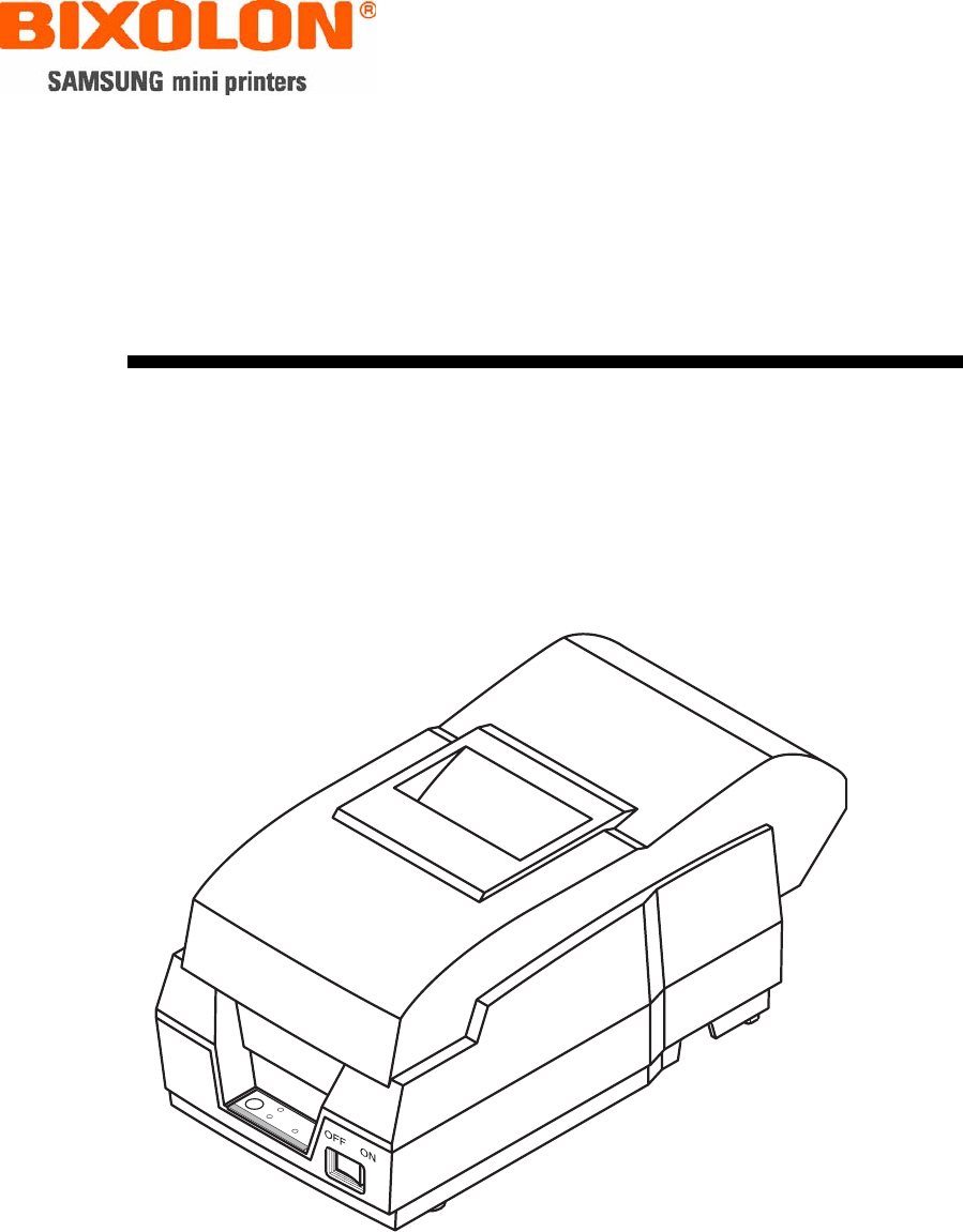
Service Manual
SRP-270
Impact Printer
Rev. 3.02
http://www.samsungminiprinters.com

Rev. 3.02 - 2 -
SRP-270
■ Table of Contents
1. Precaution Segment....................................................................................................................................6
1-1 Safety Precautions...................................................................................................................................6
1-2 Servicing Precaution................................................................................................................................7
1-3 Precaution for Electrostatically Sensitive Devices (ESDs) ......................................................................8
2. Installation and Operation ..........................................................................................................................9
2-1 Installation................................................................................................................................................9
2-1-1 AC Adapter Installation .....................................................................................................................9
2-1-2 Interface Cable Installation ...............................................................................................................9
2-1-3 Cash Drawer Cable Installation ........................................................................................................ 9
2-1-4 Ribbon Cartridge Installation.............................................................................................................9
2-1-5 Paper Roll Installation .....................................................................................................................10
2-2 Operation ...............................................................................................................................................11
2-2-1 Setting the DIP switches .................................................................................................................11
2-2-2 Setting the DIP switch (RS-232C Serial Interface) .........................................................................11
2-2-3 Setting the DIP switch (IEEE1284 Parallel, USB Interface) ...........................................................12
2-2-4 Hexadecimal Dumping....................................................................................................................13
2-2-5 The self Test Mode .........................................................................................................................13
3. Product Specifications..............................................................................................................................16
3-1 Appearance............................................................................................................................................16
3-1-1 Printer Dimensions (mm) ................................................................................................................16
3-1-2 AC Adapter Dimensions (mm) ........................................................................................................16
3-1-3 Feature Locations ...........................................................................................................................17
3-2 General Specifications...........................................................................................................................18
3-3 Printer Mecha Specifications .................................................................................................................18
3-3-1 Printer Mecha Specification ............................................................................................................18
3-3-2 Character Specification...................................................................................................................19
3-3-3 Printer (SMP-710/SMP-710N) Pin Description...............................................................................19
3-3-4 Printer Head Specification ..............................................................................................................20
3-3-5 Printer Head Thermistor Specification ............................................................................................20
3-3-6 Feed & Carriage Motor Specification..............................................................................................20
3-3-7 Auto cutter specification..................................................................................................................20
3-3-8 Paper Specification .........................................................................................................................20
3-3-9 Ribbon Cassette Specification........................................................................................................21
3-3-10 Other Component Specification....................................................................................................21
3-4 SMPS Specifications .............................................................................................................................21
3-4-1 SMPS (Switching Mode Power Supply) Specification .................................................................... 21
3-4-2 SMPS Output Connector ................................................................................................................21
3-5 Interface Specifications..........................................................................................................................22
3-5-1 RS-232C Serial Interface................................................................................................................22
3-5-2 RS-485 Serial Interface................................................................................................................... 24
3-5-3 IEEE1284 Parallel Interface............................................................................................................25
3-5-4 USB2.0 Interface.............................................................................................................................27
3-6 Cash Drawer Specifications...................................................................................................................28
3-6-1 Cash Drawer Cable......................................................................................................................... 28
3-6-2 Cable Connection ...........................................................................................................................28

Rev. 3.02 - 3 -
SRP-270
4. Hardware ....................................................................................................................................................29
4-1 Wiring Diagram ......................................................................................................................................29
4-2 Block Diagram........................................................................................................................................30
4-3 Special Circuit Descriptions ...................................................................................................................31
4-3-1 Power Circuit...................................................................................................................................31
4-3-2 RESET Circuit.................................................................................................................................32
4-3-3 Cash Drawer Circuits ......................................................................................................................33
4-3-4 I/F PBA Detect Block Diagram........................................................................................................ 34
4-3-5 RS-232C Communication Block Diagram.......................................................................................35
4-3-6 RS-485 Communication Block Diagram .........................................................................................36
4-3-7 Parallel Communication Block Diagram .........................................................................................37
4-3-8 USB Communication Block Diagram ..............................................................................................37
4-3-9 DIP Switch Circuit ...........................................................................................................................38
5. Disassembly and Assembly .....................................................................................................................39
5-1 General Precautions on Disassembly....................................................................................................39
5-2 Plate Bottom ..........................................................................................................................................39
5-3 Cover Assy (SRP-270D Type)...............................................................................................................40
5-4 Cover Assy (SRP-270A & SRP-270C Type) .........................................................................................40
5-5 Case Upper Assy (SRP-270A & SRP-270C Type)................................................................................41
5-6 Case Upper Assy (SRP-270D Type) .....................................................................................................42
5-7 Printer Assy (SRP-270A & SRP-270C Type) ........................................................................................42
5-8 Printer Assy (SRP-270D Type)..............................................................................................................43
5-9 Auto Cutter Assy....................................................................................................................................43
5-10 Main PCB.............................................................................................................................................44
5-11 Interface Board Assy ...........................................................................................................................44
6. Alignment and Adjustments.....................................................................................................................45
6-1 Printer Adjustment .................................................................................................................................45
7. Troubleshooting ........................................................................................................................................46
7-1 Power Problem ......................................................................................................................................46
7-2 System Problem.....................................................................................................................................46
7-3 Printer Problem......................................................................................................................................46
7-4 Cash Drawer Problem ...........................................................................................................................46
7-5 DIP S/W Problem...................................................................................................................................46
7-6 RS232 Problem......................................................................................................................................46
7-7 RS485 Problem......................................................................................................................................46
7-8 IEEE 1284 Problem ...............................................................................................................................47
7-9 USB Problem .........................................................................................................................................47
8. Appendix (Spec of SMP-710/710N) ..........................................................................................................48
8-1 Specifications.........................................................................................................................................48
8-1-1 Printing specifications .....................................................................................................................48
8-1-2 Character specifications..................................................................................................................49
8-1-3 Paper specifications........................................................................................................................50
8-1-4 Ribbon Cassette specifications.......................................................................................................50
8-1-4 Ribbon Cassette specifications.......................................................................................................51
8-1-5 Environmental specifications ..........................................................................................................51
8-1-6 Reliability.........................................................................................................................................52
8-1-7 Main Unit specifications ..................................................................................................................52
8-1-8 Electrical specifications...................................................................................................................53
8-1-9 Mechanisms specifications ............................................................................................................. 53
8-1-10 Principle of Movement ..................................................................................................................54

Rev. 3.02 - 4 -
SRP-270
8-2 Handling the Printer ...............................................................................................................................61
8-2-1 Precautions on Printer Handling .....................................................................................................61
8-2-2 Paper Setting Procedures (Insertion/Removal) ..............................................................................62
8-2-3 Ribbon Cassette Installation ...........................................................................................................64
8-3 Maintenance ..........................................................................................................................................65
8-3-1 Cleaning ..........................................................................................................................................65
8-3-2 Inspection........................................................................................................................................65
8-4 Lubricants and Adhesive Application.....................................................................................................66
8-4-1 Lubricant Requirements..................................................................................................................66
8-4-2 Lubricant Types ..............................................................................................................................66
8-4-3 Lubrication Points ...........................................................................................................................66
8-4-4 Adhesive Application Requirements ...............................................................................................66
8-4-5 Adhesive types................................................................................................................................66
8-4-6 Adhesive Application Points............................................................................................................66
8-5 Tools, Lubricants and Adhesives........................................................................................................... 67
8-5-1 List of Tools.....................................................................................................................................67
8-5-2 List of Lubricants and Adhesives ....................................................................................................67
8-6 Repair ....................................................................................................................................................67
8-6-1 Repair Levels ..................................................................................................................................67
8-6-2 Repair Procedures ..........................................................................................................................67
8-6-3 Repair Guidelines ...........................................................................................................................68
8-6-4 Assignment Connector Pin .............................................................................................................73
8-7 Disassembly...........................................................................................................................................74
8-8 Assembly ...............................................................................................................................................74
8-8-1 Sub-assemblies ..............................................................................................................................75
8-8-2 Main-assemblies .............................................................................................................................78
8-8-3 Adjustment ......................................................................................................................................85

Rev. 3.02 - 5 -
SRP-270
■ About
About this Manual
This Service Manual describes how to perform hardware service maintenance for the BIXOLON SRP-270
Receipt Printer.
Notes
Notes may appear anywhere in the manual. They draw your attention to additional information about the item.
Precaution symbols
Indicates a Safety Precaution that applies to this part component.
Indicates the part or component is an electro-statically sensitive device. Use caution when handling
these parts.
Copyright
ⓒ 2008 by BIXOLON Co., Ltd. All right reserved.
This Manual may not, in whole or in part, be copied, photocopied, reproduced, translated or converted to any
electronic or machine readable from without prior written permission or BIXOLON Co., Ltd.
■ Overview of this Receipt Printer
This System Receipt Printer is a microprocessor-based system, using a 16 bit-microprocessor.
This Service Manual provides the technical information for many individual component systems, circuits and
gives an analysis of the operations performed by the circuits. If you need more technical information, please
contact our service branch or R&D center. Schematics and specifications provide the needed information for
the accurate troubleshooting.
All information in this manual is subject to change without prior notice. Therefore, you must check the
correspondence of your manual with your machine. No part of this manual may be copied or reproduced in
any form or by any means, without the prior written consent of BIXOLON Co., Ltd.

Rev. 3.02 - 6 -
SRP-270
1. Precaution Segment
Follow these safety, servicing and ESD precautions to prevent damage and to protect against potential
hazards such as electrical shock.
1-1 Safety Precautions
1. Be sure that all of the built-in protective devices are replaced. Restore any missing protective shields.
2. When reinstalling the chassis and its assemblies, be sure to restore all protective devices, including
nonmetallic control knobs and compartment covers.
3. Make sure that there are no cabinet openings through which people - particularly children - might
insert fingers and contact dangerous voltages. Such openings include excessively wide cabinet
ventilation slots and improperly fitted covers and drawers.
4. Leakage Current Hot Check:
WARING: Do not use an isolation transformer during this test.
Use a leakage-current tester or a metering system that complies with American National Standards
Institute (ANSI C101.1, Leakage Current for Applications), and Underwriters Laboratories (UL Publications
UL1410, 59.7)
With the unit completely reassembled, plug the AC line cord directly into a 100VAC or 240VAC outlet of the
Adaptor.
With the unit’s AC switch first in the ON position and then OFF, measure the current between a
known Earth ground (metal water pipe, conduit, etc.) and all exposed metal part, including: metal cabinet,
frame, and screw-heads and printer. The current measure should not exceed 0.1 milliamp. Reverse the
power-plug prong in the AC outlet and repeat the test.
5. Design Alteration Warning:
Never alter or add to the mechanical or electrical design of the Receipt Printer. Unauthorized alterations
might create a safety hazard. Also any design changes or additions will void the manufacture’s warranty.
6. Components, parts and wiring that appear to have overhead or that are otherwise damaged should be
replaced with parts that meet the original specifications. Always determine the cause of damaged or
overheating and correct any potential hazards.
7. Observe the original lead dress, especially near the following areas: sharp edges, and especially the AC
and high voltage supplies. Always inspect for pinched, out-of-place, or frayed wiring.
Do not change the spacing between components and the printed circuit board. Check the AC power cord
for damage. Make sure that leads and components do not touch thermally hot parts.
8. Product Safety Notice:
Some electrical and mechanical parts have special safety-related characteristics, which might not be
obvious from visual inspection. These safety features and the protection they give might be lost if the
replacement component differs from the original-even if the replacement is rated for higher voltage,
wattage, etc.
Components that are critical for safety are indicated in the circuit diagram by shading,
( )or ( ). Use replacement components that have the same ratings, especially for flame resistance
and dielectric strength specifications. A replacement part that does not have the same safety
characteristics as the original might create shock, fire or other hazards.

Rev. 3.02 - 7 -
SRP-270
1-2 Servicing Precaution
WARNING 1: First read the Safety Precaution section of this manual. If some unforeseen
circumstance creates a conflict between the servicing and safety precautions,
always follow the safety precaution.
WARNING 2: An electrolytic capacitor installed with the wrong polarity might explode.
1. Always unplug the unit’s AC power cord from the AC power source or the Power Switch off before
attempting to:
(a) Remove or reinstall any component or assembly,
(b) Disconnect an electrical plug or connector,
(c) Connect a test component in parallel with an electrolytic capacitor.
2. Some components are raised above the printed circuit board for safety.
An insulation tube or tape is sometime used. The internal wiring is sometimes clamped to prevent contact
with thermally hot components. Reinstall all such elements to their original position.
3. After servicing, always check that the screws, components and wiring have been correctly reinstalled.
Make sure that the portion around the serviced part has not been damaged.
4. Check the insulation between the blades of the AC plug and accessible conductive parts.
(example: metal panels and input terminals).
5. Insulation Checking Procedure:
Disconnect the power cord from the AC source and turn the power switch ON. Connect an insulation
resistance meter (500V) to the blades of the AC plug. The insulation resistance between each blade of the
AC plug and accessible conductive parts (see above) should be greater than 1 mega-ohm.
6. Never defeat any of the B+ voltage interlock. Do not apply AC power to the unit (or any of its assemblies)
unless all solid-state heat sinks are correctly installed.
7. Always connect an instrument’s ground lead to the instrument chassis ground before connecting the
positive lead; always remove the instrument’s ground lead last.

Rev. 3.02 - 8 -
SRP-270
1-3 Precaution for Electrostatically Sensitive Devices (ESDs)
1. Some semiconductor (solid state) devices are easily damaged by static electricity. Such components are
called Electrostatically Sensitive Devices (ESDs); examples include integrated circuits and some field-
effect transistors. The following techniques will reduce the occurrence of component damaged caused by
static electricity.
2. Immediately before handling any semiconductor components or assemblies, drain the electrostatic charge
from your body by touching a known earth ground. Alternatively, wear a discharging wrist-strap device.
(Be sure to remove it prior to applying power-this is an Electric shock precaution.)
3. After removing an ESD-equipped assembly, place it on a conductive surface such as aluminum foil to
prevent accumulation of electrostatic charge.
4. Do not use freon-propelled chemical. These can generate electrical charges that damage ESDs.
5. Use only a grounded-tip soldering iron when soldering or unsoldering ESDs.
6. Use only an anti-static solder removal device. Many solder removal devices are not rated as anti-static;
these can accumulate sufficient electrical charge to damage ESDs.
7. Do not remove a replacement ESD from its protective package until you are ready to install it.
Most replacement ESDs are packaged with leads that are electrically shorted together by conductive foam,
aluminum foil or other conductive materials.
8. Immediately before removing the protective material from the leads of a replacement ESD, touch the
protective material to the device will be installed.
9. Minimize body motions when handling unpacked replacement ESDs. Motions such as brushing clothes
together, or lifting a foot from a carpeted floor can generate enough static electricity to damaged an ESD.
Rev. 3.02 - 9 -
SRP-270
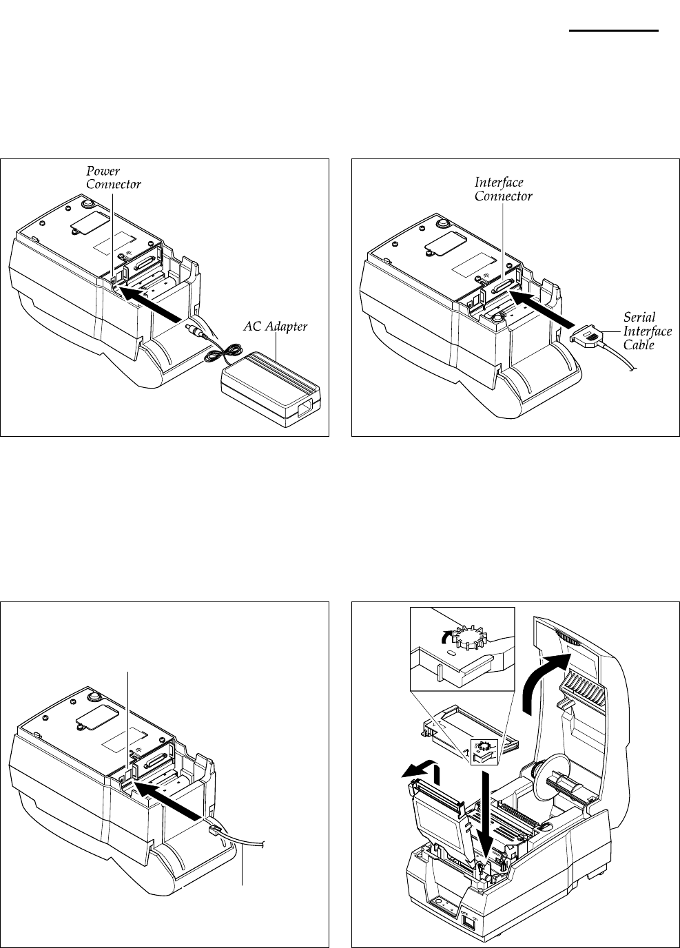
2. Installation and Operation
2-1 Installation
2-1-1 AC Adapter Installation 2-1-2 Interface Cable Installation
1. Mack sure the printer is turned off with the “Off”
side of the switch is pressed down.
2. Check the label on the AC Adapter to make sure the
voltage required by the AC Adapter matches that of the
electrical outlet.
3. Plug the DC cord connector into the power jack on the
printer.
4. Plug the AC Adapter power cord into the wall outlet.
2-1-3 Cash Drawer Cable Installation
1. Turn off the printer, host ECR and Computer.
2. Plug RS-232, RS-485, USB or Parallel Cable
connector into the I/F connector on the printer.
3. Tighten the screws on both sides of the connector.
4. Turn on the printer, host ECR and Computer.
2-1-4 Ribbon Cartridge Installation
1. Turn the printer off.
2. Plug the Cash Drawer cable connector into the
connector on the printer. (To remove the Cash Drawer
cable, press the clip on the connector, grasp the
connector and pull it out.)
3. Secure the Shield Wire on the bottom of the printer.\
1. Before inserting the ribbon cartridge, turn the Knob.
2. Insert the ribbon cartridge. Pay particular attention to
the placement of the ribbon behind the Print Head.
3. After inserting the ribbon cartridge, turn the knob
clockwise again to make sure the ribbon moves freely
in the cartridge.
Cash Drawer Connector
Cash Drawer Cable
Rev. 3.02 - 10 -
SRP-270
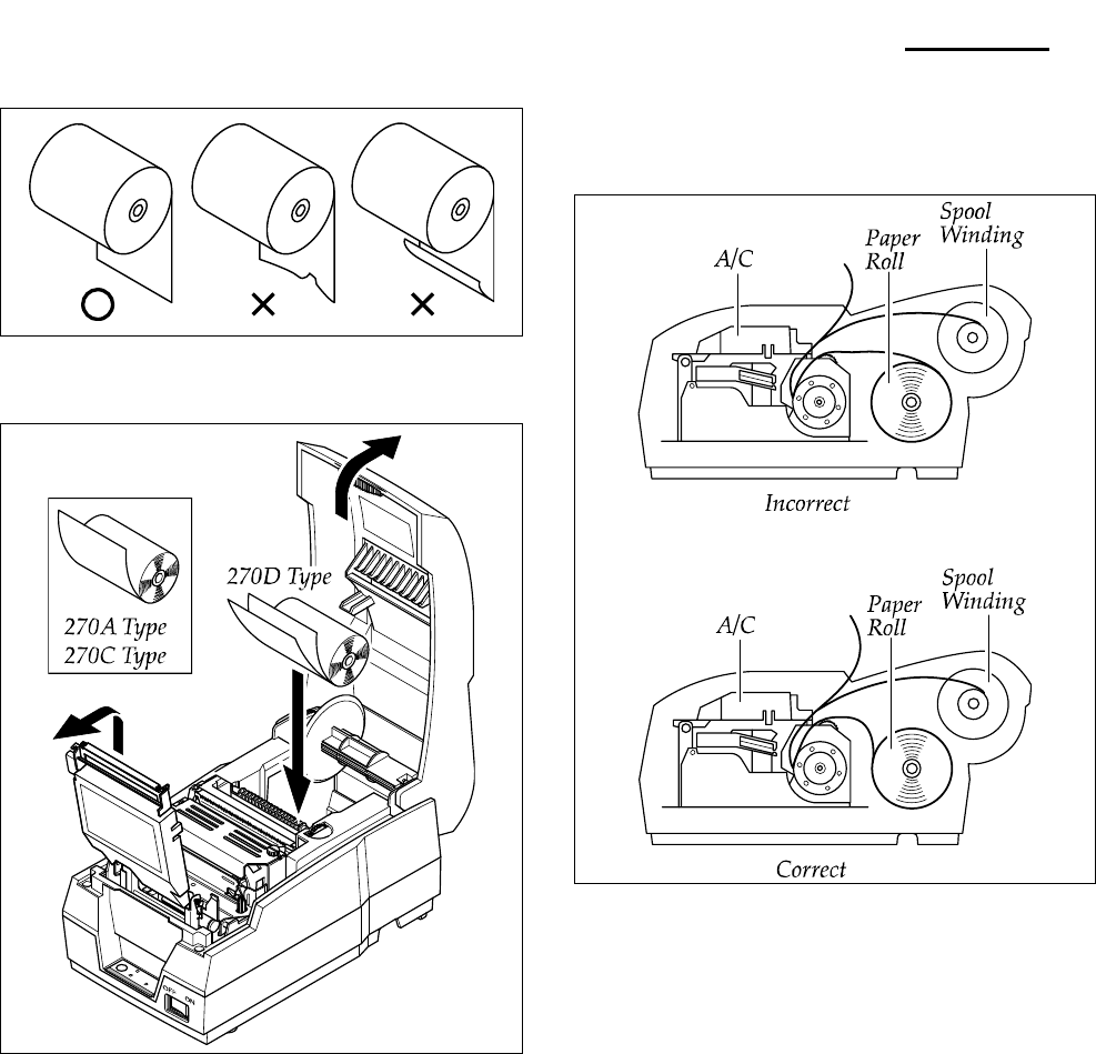
2-1-5 Paper Roll Installation
1. Using a new roll paper, unroll the paper and cut the end
as shown.
2. In case of Model 270C/D, open Auto Cutter on the
power ON.
3. Auto feeding one paper.
4. Put first paper into Auto Cutter, set second paper rolling
Spool Winding to Lower Case.
5. Setting Auto Cutter, then put first paper to the middle of
guide for cover Printer and pull it out close cover.
6. If the paper is loose, wind the Rewind Spindle to tighten
the paper.
7. Release the holder after fitting the Roll Paper Core onto
the Holder. Make sure to load the paper roll so that it
rotates in the correct direction.
Rev. 3.02 - 11 -
SRP-270
2-2 Operation
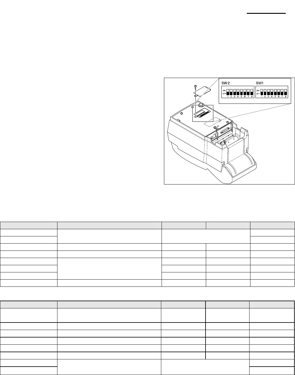
2-2-1 Setting the DIP switches
The DIP switches are located on the bottom of the printer. The DIP switches are used to set the printer to perform various
functions. Follow these when changing DIP switches setting :
1. Turn the printer power switch off.
2. Remove the screw on the bottom of the printer and
open the bracket.
3. Flip the DIP switches using tweezers or another narrow-
ended tool. Switches are on when up and off when off
down.
4. The new setting takes effect when you turn on the
printer.
※ Note : Always change DIP switch settings only when the
printer is turned off. Change made with the power
on have no effect and then on again.
2-2-2 Setting the DIP switch (RS-232C Serial Interface)
• DIP Switch 1
SW FUNCTION ON OFF DEFAULT
1 OFF
2 Emulation Selection Refer to the following Table 1 OFF
3 Auto-Cutter Enable Disable OFF
4 FONT SPACE 2 3 OFF
5 -
6 -
7
Function for Service Engineer
OFF
8 Korean Type Selection Unified Complete OFF
• DIP Switch 2
SW FUNCTION ON OFF DEFAULT
1 Auto Line Feed Always
Enabled
Always
Disabled OFF
2 Hexadecimal dump YES NO OFF
3 Hand Shaking XON/OFF DTR/DSR OFF
4 Word length 7 bits 8 bits OFF
5 Parity check Enable Disable OFF
6 Parity selection EVEN ODD OFF
7 OFF
8 Baud Rate selection Refer to the following Table 2 OFF
NOTE※
When the word length is 7 bits, you can not parity check OFF status.
Rev. 3.02 - 12 -
SRP-270
2-2-3 Setting the DIP switch (IEEE1284 Parallel, USB Interface)
• DIP Switch 1
SW FUNCTION ON OFF DEFAULT
1 OFF
2 Emulation Selection Refer to the following Table 1 OFF
3 Auto-Cutter Enable Disable OFF
4 FONT SPACE 2 3 OFF
5 -
6 -
7
Function for Service Engineer
OFF
8 Korean Type Selection Unified Complete OFF
• DIP Switch 2
SW FUNCTION ON OFF DEFAULT
1 Auto Line Feed Always
Enabled
Always
Disabled OFF
2 Hex Dump YES NO OFF
3 Reserved - - OFF
4 Reserved - - OFF
5 Reserved - - OFF
6 Reserved - - OFF
7 Reserved - - OFF
8 Reserved - - OFF
• Table 1 – Emulation Selection
SW – 1 SW – 2 MODE
OFF OFF Epson
OFF ON Citizen
ON OFF Star
• Table 2 – Baud rate (bps) Selection
Transmission speed SW – 7 SW – 8
19200 baud ON ON
2400 baud OFF ON
4800 baud ON OFF
9600 baud OFF OFF

Rev. 3.02 - 13 -
SRP-270
2-2-4 Hexadecimal Dumping
This feature allows experienced users to see exactly what data is coming to the printer. This can be useful in
finding software problems. When you turn on the hexadecimal dump function, the printer prints all commands
and data in hexadecimal format along with a guide section the help you find specification commands.
To use hexadecimal dump mode, please follow these steps:
1. After you make sure that the printer is off.
2. Set DIP-switch 2-2to ON.
3. Turn on the printer, and then the printer enters the hexadecimal dump mode.
4. Run any software program to send data to the printer. The printer will print all the codes it receives in a
two-column format. The first column contains the hexadecimal codes and the second column gives the
ASCII characters corresponding to the codes.
1B 21 00 1B 26 02 40 40 . ! . . & . @ @
02 0D 1B 44 OA 14 1E 28 ...D...(
00 01 0A 41 OD 42 OA 43 . . . A . B . C .
Note 1 : A period(.)is printed for each code that no ASCII equivalent.
Note 2 : During the hex dump all the commands except DLE EOT and DLE ENQ are disabled.
5. When the printing finishes, turn off the printer, and change DIP-switch 2-2 to OFF.
6. Turn on the printer and then the hexadecimal mode is off.
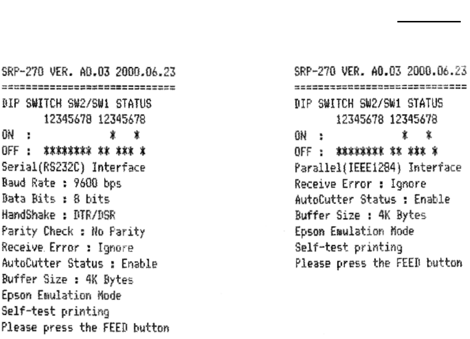
2-2-5 The self Test Mode
The self-test checks whether the printer has any problem. If the printer does not function properly, contact
your dealer. The self-test checks the following.
1. Make sure paper roll has been installed properly.
2. Turn on the printer power while holding down the FEED button so that the self-test begins.
3. The self-test prints the current printer status, which provides the control ROM version and the DIP switch
setting.
4. After printing the current printer status self-test printing will print the following and pause.
(The PAPER OUT and ERROR LED’s light blinks.)
Please press the button
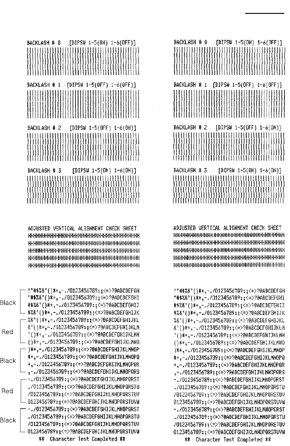
5. Press the FEED button to continue printing. The printer prints a pattern using the built-in character set.
6. The character test sheet to be printed is that four lines are printed as BLACK color and the next four lines
are printed as RED color in turn. Total 20 character lines will be printed.
7. The self-test automatically ends and cuts the paper after printing the following.
** Character Test Completed **
8. Back-Lash printing is possible when the DIP switch 1-7 is ON, or the printing is skipped when the DIP
switch 1-7 is OFF.
9. The printer is ready to receive data as soon as it completes the self-test.
Rev. 3.02 - 14 -
SRP-270
(A) Serial Self-Test Sheet (B) Parallel Self-Test Sheet
Rev. 3.02 - 15 -
SRP-270
(A) Serial Self-Test Sheet (B) Parallel Self-Test Sheet
Rev. 3.02 - 16 -
SRP-270
3. Product Specifications
3-1 Appearance
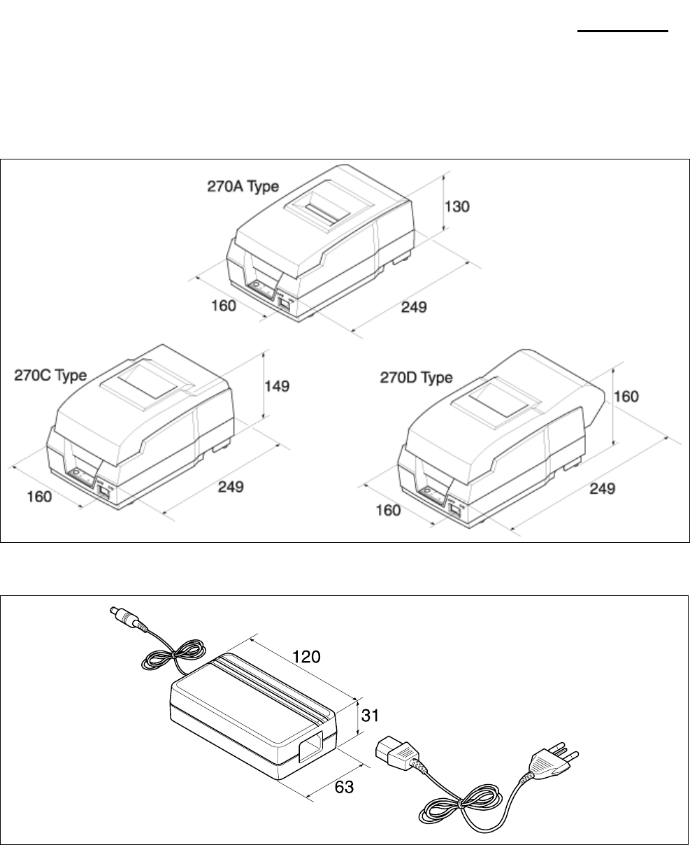
3-1-1 Printer Dimensions (mm)
Figure 3-1 Printer Dimension
3-1-2 AC Adapter Dimensions (mm)
Figure 3-2 Adapter Dimension
Rev. 3.02 - 17 -
SRP-270
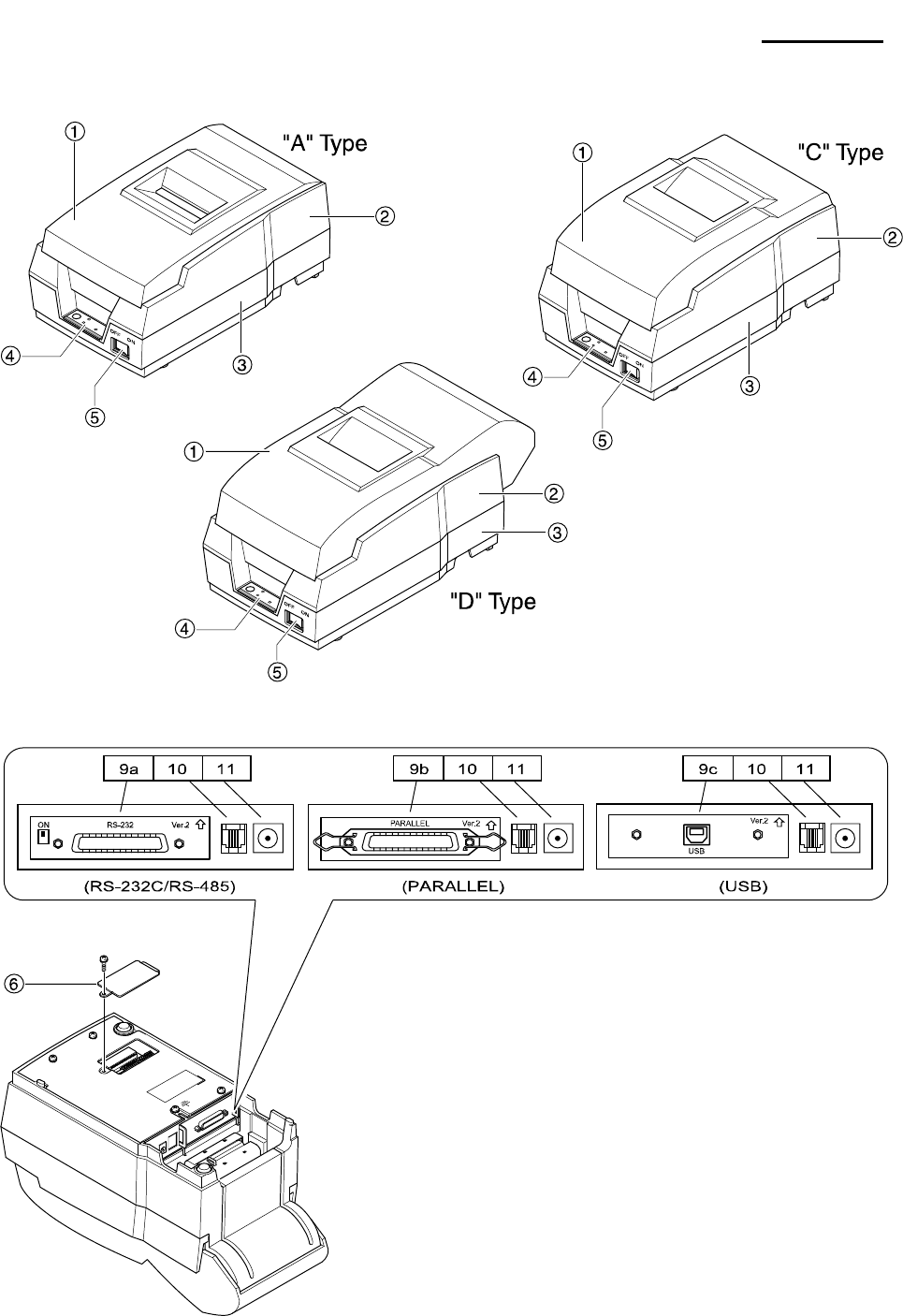
3-1-3 Feature Locations
Figure 3-3 Feature Location
1. Cover, A/C/D
2. Case-Upper, A/C/D
3. Case-Lower, A/C/D
4. Label-Control
5. Power Switch
6. Bracket DIP Switch
9a.RS-232C/RS-485 (Serial I/F Connector)
9b.IEEE-1284(Parallel I/F Connector)
9c.USB(USB I/F Connector)
10. Drawer Kick-Out Connector
11. DC Power Jack

Rev. 3.02 - 18 -
SRP-270
3-2 General Specifications
Item Description Remark
Product
• SRP-270 : RS-232 Serial Communication
• SRP-270S : RS-485 Serial Communication
• SRP-270P : IEEE1284 Parallel Communication
• SRP-270U : USB Communication
Processor • MITSUBISHI M16C/62 Group M30622 SFP (16 Bit)
Internal RAM Size : 3K Byte External ROM Version
Memory • EPROM : 1Mbits (M27C010)
• SRAM : 256Kbits (KM62256)
Interface Serial
(RS-232C / RS-485)
• Flow Control :
1) DTR / DSR (H/W Flow Control)
2) XON / XOFF (S/W Flow Control)
• Baud Rate : 1200 / 2400 / 4800 / 9600 Bps
• Receive Buffer : 4 Kbytes
• Connector : DB25P Female (I/F PBA Side)
The Flow Control, Baud
Rate, Stop Bit and Parity
are determined by DIP
S/W position.
Interface Parallel
• Mode :
1) Forward Mode : Compatibility Mode
2) Reverse Mode : Nibble / Byte Mode
• Connector : Self-Powered
USB
• Transfer Type : BULK
• Speed : 12 Mbps (Full-Speed)
• Power : Self-Powered
Printer • Printing Method : 9pins Impact Serial Dot
• Printing Speed : 4.6 Line/Sec
Auto Cutter • Type : Guillotine
• Cutting Method : 1 Point Partial Cutting
Power Consumption • Approx. 24W
AC Adapter • Input : AC 100V ~ 240V, 50Hz/60Hz
• Output : DC 24V±5%, 1.5A
Environment
Condition
• Temperature : 0℃ ~ 40℃
• Humidity : 30% ~ 80% RH
Weight • 3.2 Kg (A Type) / 3.5 Kg (C Type) / 3.6 Kg (D Type)
• 2.2 Kg (A Type) / 2.5 Kg (C Type) / 2.6 Kg (D Type)
Packing
Unpacking
Dimensions(mm)
• A Type : 160 X 249 X 130
• C Type : 160 X 249 X 149
• D Type : 160 X 249 X 160
Reliability
• Head: 300 million dots
• Printer: 18 million lines (MCBF)
• Auto Cutter: 1 million cuts
3-3 Printer Mecha Specifications
3-3-1 Printer Mecha Specification
Item Description Remark
Model • SMP-710/SMP-710N
Print Method • Serial Impact Dot Matrix type (9-Pin Dot)
Printing Direction • Bi-Direction
Printing Speed • 4.6 Lines / Sec (9 x 7 Font 40 Columns)
Printing Resolution • 160(W) x 144(L) DPI
Paper Feeding • Performed by Step Motor
Paper • Rolled Paper : W 76±0.5 x Max ø 83mm
Supply Voltage • 24V ± 10% : Step Motor, Head
• 5V ± 10% : Home Sensor, Motor Driver IC
Connector • 30P (Dot Head, Sensor Signal, Motor Control and Power Input)
• LIFE : Approx.20 Million Print Lines
Head Life • Approx. 300 million Dots / Wire
Weight • Under 650g (Excluding Ribbon Cassette, Auto Cutter)

Rev. 3.02 - 19 -
SRP-270
3-3-2 Character Specification
Item Description Remark
H 0.3175 mm
Dot Interval V 0.3528 mm
Font Type ASCII Chinese
Print Font 9 x 9 7 x 9 16 x 16
Printing Columns 33 40 -
Character Size (mm) 3.2 x 1.7 3.2 x 1.4 5.7 x 3.0
Column Interval (mm) 2.13 1.59 3.19
Line Interval 1/6“ 1/6“ 1/3“
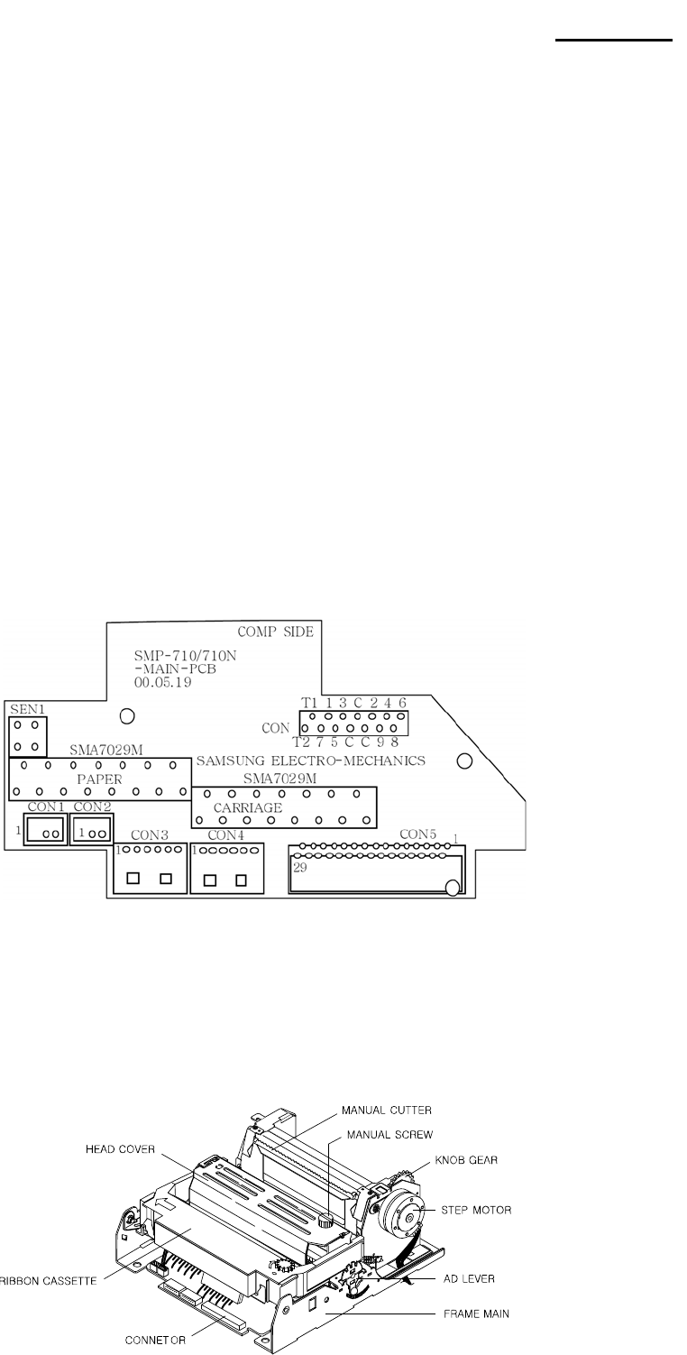
3-3-3 Printer (SMP-710/SMP-710N) Pin Description
Pin No. Pin Name Descriptions
1 Printer Head Head #6
2 Printer Head Head #8
3 Printer Head Head #4
4 Printer Head Head #9
5 Printer Head Head #2
6 +24Vdc The Voltage for Driving Print Heads
7 +24Vdc The Voltage for Driving Print Heads
8 +24Vdc The Voltage for Driving Print Heads
9 Print Head Head #3
10 Printer Head Head #5
11 Printer Head Head #1
12 Printer Head Head #7
13 Thermistor Thermistor Output Value in Printer Head
14
15
16
17
GND -
18 Carriage Motor ON/OFF Control Driving voltage or Holding Voltage Of Carriage Motor
19 Carriage Motor A Phase A of the Carriage Motor
20 Carriage Motor B Phase B of the Carriage Motor
21 Vcc (+5 Vdc) -
22 Vcc -
23 Feed Motor ON/OFF Control, Driving Voltage or Holding Voltage of Feed Motor
24 Feed Moter A Phase A of the Feed Motor
25 Feed Moter B Phase B of the Feed Motor
26 H/S Output -
27 P/E Output -
28 +24 Vdc The Voltage for Driving Motors
29 +24 Vdc The Voltage for Driving Motors
30 Sol- -

Rev. 3.02 - 20 -
SRP-270
3-3-4 Printer Head Specification
Item Description Remark
Model • DH400-G10
Specification • Type: Ballistic Type (Free Fight)
• Number of Wire: 9Pin
Solenoid Coil
• Resistance: 10W ± 15%
• Inductance: 4.5mH ± 15% (Open Circuit)
• Temperature Rate: 155 Deg.C
• Insulation Resistance: 10MW
Driver Circuit
• Type: constant Voltage
• voltage: 24VDC ± 5% (Normal ) (At Printer Head)
• Current: 1.3 A
• Pulse: 330μ Sec (Head On Time)
• Fly Back Voltage: 48VDC (Min)
Performance
• Platen Gap: 0.51 ± 0.1 mm
• Max Frequency: 1500 Hz
• Forms Capability: Original + 2 Copies
Temperature • Max Operating Temp: 65°C
• Max Transient Temp: 140°C (For 5 Minutes)
3-3-5 Printer Head Thermistor Specification
Item Description Remark
Type • LP310-1J (Tama Elec. Co., Ltd) or
Correspond to it correspond to it
Any thermistor which
correspond to it
Electronic
Characteristics
• Resistance R25: 17.3 KW (At 25°C)
• B Value: 3950K ± 2
Max Operating Limit • Operating Temp: 120°C ~ 150°C
• Time Constant: Max 30 sec (In the air)
Rx Formula • RX = R25 x Exp {B x (1/TX -1/T25) ]} T : Absolute Temperature
3-3-6 Feed & Carriage Motor Specification
Item Description Remark
Model • PM42S-048-SYM4 (NMB Electronic Co., Ltd)
Voltage • 24 VDC ± 10%
Current • 500 mA / Phase (Peak)
Resistance • 10 W
Step Angle • 7.5°
Pull Out Torque • 1200 PPS 200 g/cm
3-3-7 Auto cutter specification
Item Description Remark
Model • ORC-RUG80-2 (OHYANERIKI MFG. Co., Ltd)
Type • Guillotine Type
Motor • DC Brush Motor Fk-180SH-12280 Mabuchi Motor
Voltage • 24VDC ± 10%
Current • 400 mA (Average), 1.6 A (Peak)
3-3-8 Paper Specification
Item Description Remark
Paper Type • Roll Paper
Paper Roll Width • W76 ± 0.5 mm (2.99” ± 0.00200”)
Paper Roll Diameter • Max x ø 83mm (3.26”)
Normal Paper
• Thickness: 1 Sheet 0.06~0.085mm
(0.0028 ~ 0.0034”)
• Weight: 52.3 ~64 g/m2 (0.115 ~ 0.1411 lb)
Rev. 3.02 - 21 -
SRP-270
3-3-9 Ribbon Cassette Specification
Item Description Remark
Standard • ERC-38 (Black / Red)
Color • Black & Red
Size • 13 mm (W) x 6 mm (L)
Life
• ERC-38 (B/P): 1,500,000 Characters (Black)
750,000 Character (Red)
(Continuous Printing 7 x 9 Font / ASCII / 25 )℃
3-3-10 Other Component Specification
Item Description Remark
Paper End Sensor • Reflection Type Micro Switch
Paper Roll Near End
Sensor • Micro Switch Factory option
3-4 SMPS Specifications
3-4-1 SMPS (Switching Mode Power Supply) Specification
Item Description Remark
Input Voltage • 100VAC ~ 240VAC
Input Current • 1.5A (Max)
Line Regulation • +24V ± 1%
Load Regulation • +24V ± 5%
Ripple Noise • Peak 300mV
O.C.P • 2.3A ~ 2.5A (Over Current Protect)
3-4-2 SMPS Output Connector
Pin Number Signal Name
1 +24 VDC
2 GND
Power Connector
Rev. 3.02 - 22 -
SRP-270
3-5 Interface Specifications
3-5-1 RS-232C Serial Interface
3-5-1(a) Specification
Item Description Remark
Data Transmission • Serial
Synchronization • Asynchronous
HandShaking
(Flow Control)
• H/W : DTR / DSR
• S/W : XON / XOFF
XON: ASC Code 11h
XOFF: ASC Code 13h
Signal Level • Logic”1” (MARK) : -3V ~ -15V
• Logic”0” (SPACE) : +3V ~ +15V
Baud Rate • 19200 / 2400 / 4800 / 9600 Bps
Data Word Length • 7 Bit / 8 Bit
Parity • None / Even / Odd
Connector • DB25P Female (I/F PBA)
Table 3-14 RS-232C Specification
※ Note: The HandShaking (Flow Control) / Data Word Length / Baud Rate / Parity functions depend
on the DIP Switch settings. Refer to the User’s Manual.
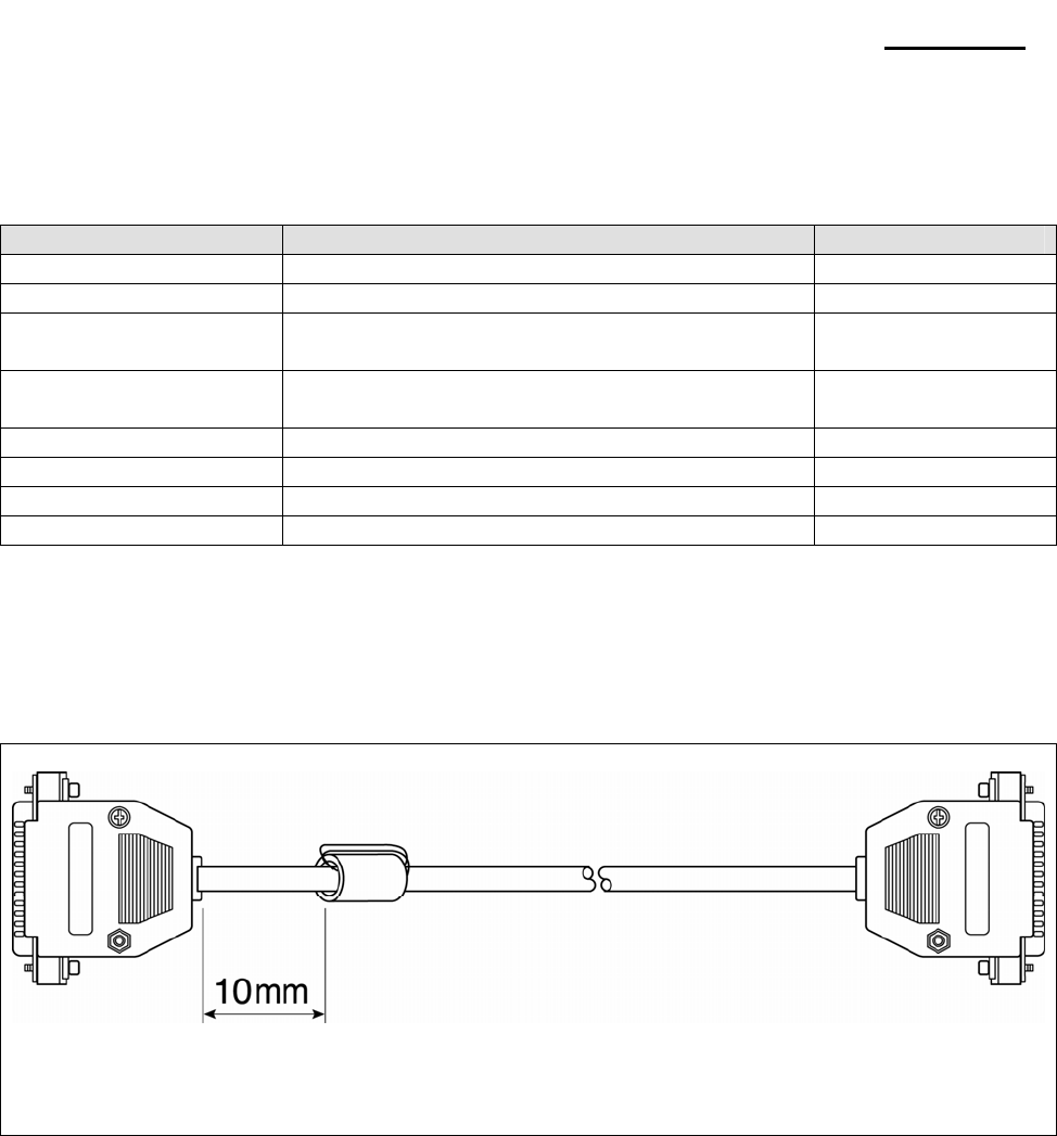
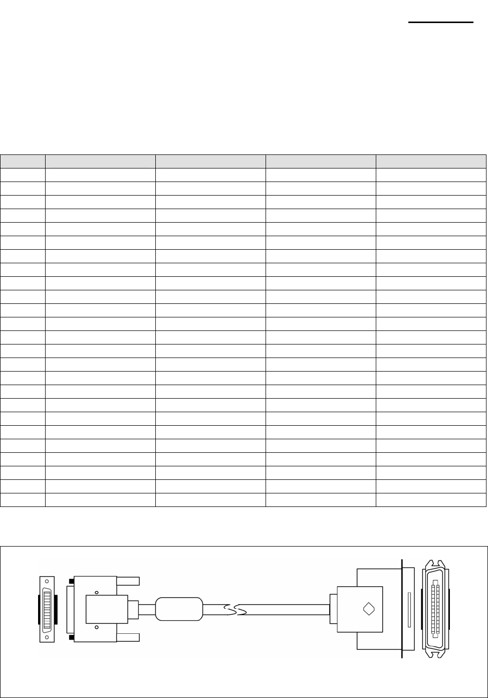
3-5-1(b) RS-232C I/F Cable
Printer Side: D-SUB25P-Male
Ferrite Core : 1 Turn (OP-118E : 18.2 x 12.5 x 25.5)
CONN : User Spec
In Case PC : D-SUB25P-Female or
D-SUB9P-Female
Figure 3-6 RS-232C Cable
Rev. 3.02 - 23 -
SRP-270
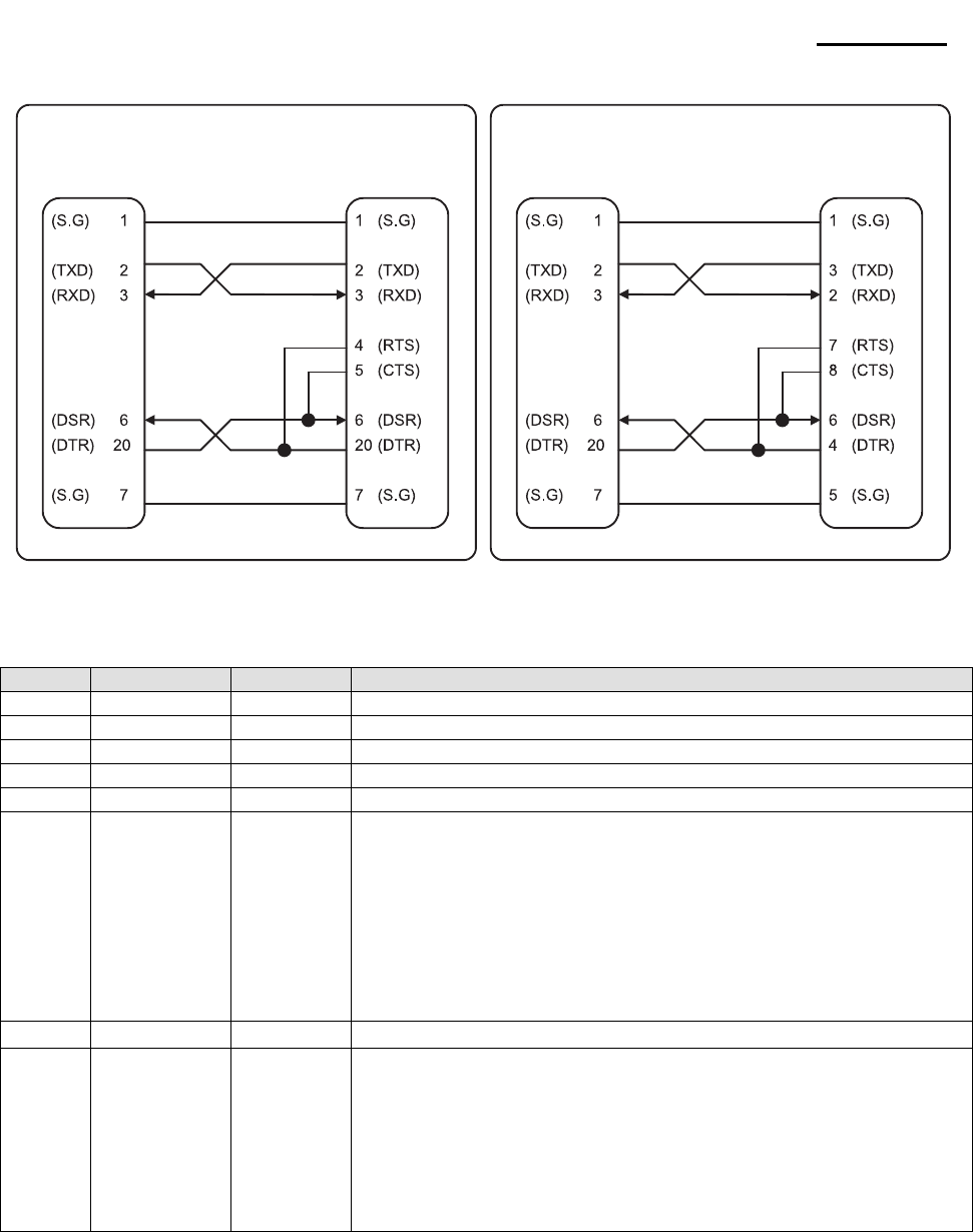
3-5-1(c) Cable Connection
Figure 3-7 RS-232C Cable Connection
3-5-1(d) Signal Description
Pin No. Signal name Direction Function
1 FG - Frame Ground
2 TxD Output Transmit Data
3 RxD Input Receive Data
4 RTS Output Ready To Send
5 CTS Input Clear To Send
6 DSR Input
This signal indicates whether the host computer can receive data.
(H/W flow control)
1) MARK(Logic1) : The host can receive a data.
2) SPACE(Logic0) : The host can not receive a data.
3) The printer transmits a data to the host, after confirming
this signal.
4) When XON/XOFF flow control is selected, the printer does
not check this signal.
7 SG -
Signal Ground
20 DTR Output
This signal indicates whether the printer is busy. (H/W flow control)
1) MARK(Logic1) : The printer is busy.
2) SPACE(Logic0) : The printer is not busy.
3) The host transmits a data to the printer, after confirming
this signal.
4) When XON/XOFF flow control is selected, the host does not
check this signal.
Table 3-15 RS-232C Pin Description
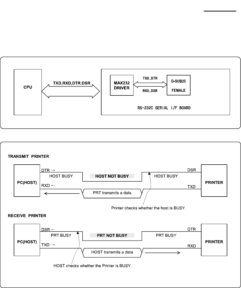
3-5-1(e) H/W Flow Control
When DTR/DSR flow control is select, before transmitting a data, the Printer checks whether the host is
BUSY or not. If the host is BUSY, the Printer does not transmit a data to the host. If the host is not BUSY, the
Printer transmits a data to the Host. The host is the same. Refer to the Interface Part of Chapter 4-3 Special
Circuit Diagrams.
PRINTER
SIDE (25P)
HOST
SIDE (25P)
PRINTER
SIDE (25P)
HOST
SIDE (9P)
Rev. 3.02 - 24 -
SRP-270
3-5-1(f) S/W Flow Control
When XON/XOFF flow control is selected, the printer transmits XON(ACSII 11h) or XOFF(ASCII 13h) signal
through the TXD line. If the Printer is BUSY, the Printer transmits XOFF(ASCII 13h) to host through the TXD
line. Then the host recognize that the Printer is BUSY. So, the host does not transmit a data to the Printer. If
the Printer is released from BUSY, the Printer transmits XON(ASCII 11h) to host through the TXD line. Then
the host recognize that the Printer is not BUSY. And the host transmit a data to the Printer.
※ Note : Refer to the Operation Manual about XON/XOFF flow control.
3-5-2 RS-485 Serial Interface
3-5-2(a) Specification
Item Description Remark
Data Transmission • Serial
Synchronization • Asynchronous
HandShaking
(Flow Control)
• H/W : DTR / CTS (Same as DSR)
• S/W : XON / XOFF
XON: ASC Code 11h
XOFF: ASC Code 13h
Signal Level • Logic”1” : SD1-SD2 ≥ 0.2V, RD1-RD2 ≥ 0.2V
• Logic”0” : SD1-SD2 ≤ 0.2V, RD1-RD2 ≤ 0.2V
Baud Rate • 19200 / 2400 / 4800 / 9600 Bps
Data Word Length • 7 Bit / 8 Bit
Parity • None / Even / Odd
Connector • DB25P Female (I/F PBA)
Table 3-16 RS-485 Specification
※ Note : The HandShaking (Flow Control) / Data Word Length / Baud Rate / Parity functions depend
on the DIP Switch settings. Refer to the User’s Manual.
3-5-2(b) RS-232C I/F Cable
Same as the appearance of RS-232C Cable
3-5-2(c) Cable Connection
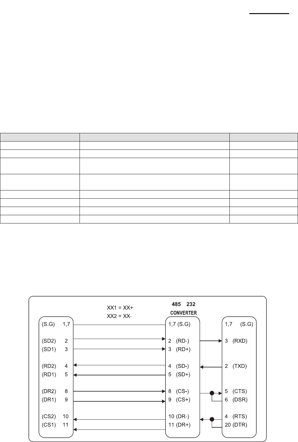
Figure 3-8 RS-485 Cable Connection
PRINTER
SIDE
HOST
SIDE
Rev. 3.02 - 25 -
SRP-270
3-5-2(d) Signal Description
Pin No. Signal name Direction Function
1 Frame GND - Frame Ground
2 SD2 Output
3 SD1 Output
Send Data
”H” : SD1 > SD2 , “L” : SD1 < SD2
4 RD2 Input
5 RD1 Input
Receive Data
”H” : RD1 > RD2 (RD1-RD2 ≥ 0.2V)
“L” : RD1 < RD2 (RD1-RD2 ≤ 0.2V)
7 SGND - Signal Ground
8
9
DR2
DR1 Output
When DTR/DSR is selected, this signal indicates whether the printer is
BUSY or READY. (H/W flow control)
1) DR1 > DR2 (H) : The printer is BUSY.
2) DR1 < DR2 (H) : The printer is READY.
3) The host computer transmits a data to the host,
after confirming this signal.
10
11
CS2
CS1 Input
When DTR/DSR is selected, this signal indicates whether the host
computer is BUSY or READY. (H/W flow control)
1) CS1 > CS2 (H) : The host computer is BUSY.
2) CS1 < CS2 (H) : The host computer is READY.
3) The printer transmits a data to the host, after confirming this signal.
Table 3-17 RS-485 Pin Description
※ Note : BUSY condition and other information refer to the User’s Manual.
※ Note : This format is used when the UART for RS-232C is connected to the RS-485 driver.
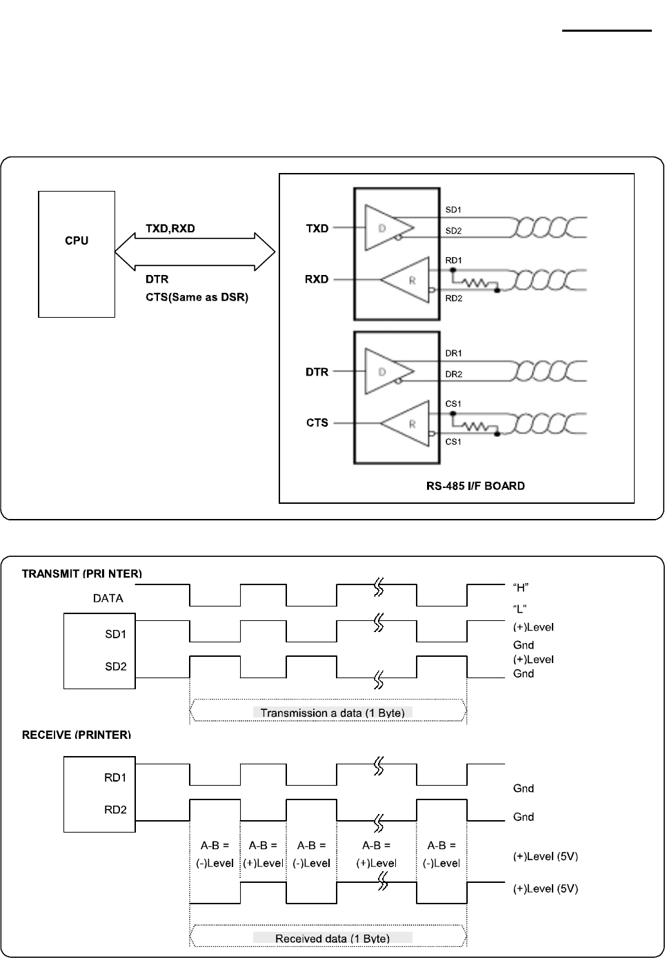
3-5-2(e) H/W Flow Control
When DR1,2/CR1,2 flow control is select, before transmitting a data, the Printer checks whether the host is
BUSY or not. If the host is BUSY, the Printer does not transmit a data to the host. If the host is not BUSY, the
Printer transmits a data to the Host. The host is the same. Refer to the Interface Part of Chapter 4-3 Special
Circuit Diagrams.
3-5-2(f) S/W Flow Control
When XON/XOFF flow control is selected, the printer transmits XON(ACSII 11h) or XOFF(ASCII 13h) signal
through the TXD line. If the Printer is BUSY, the Printer transmits XOFF(ASCII 13h) to host through the TXD
line. Then the host recognize that the Printer is BUSY. So, the host does not transmit a data to the Printer. If
the Printer is released from BUSY, the Printer transmits XON(ASCII 11h) to host through the TXD line. Then
the host recognize that the Printer is not BUSY. And the host transmit a data to the Printer.
※ Note : Refer to the Operation Manual about XON/XOFF flow control.
3-5-3 IEEE1284 Parallel Interface
Bidirectional parallel interface : in accordance with the IEEE1284 Nibble/Byte mode.
3-5-3(a) Forward Mode Specification (Compatibility mode)
Data transmission from host computer to printer : Centronics compatiable
Item Description Remark
Data Transmission • 8-bit Parallel
Synchronization • External supplied nStrobe signals
HandShaking • nACK and Busy signals
Signal Level • TTL compatiable
Connector • Centronics 36P
Table 3-18 IEEE1284 Specification
Rev. 3.02 - 26 -
SRP-270
3-5-3(b) Reverse Mode Specification (Nibble / Byte mode)
Data transmission from the printer to the host computer.
The STATUS data transmission from the printer to the host computer is accomplished in the Nibble or Byte
mode. This mode allows data transmission from the asynchronous printer under the control of the host
computer. Data transmission in the Nibble mode are made via the existing control lines in units of for bits
(Nibble). In the Byte mode, data transmission in accomplished by making the 8-bit data lines bidirectional.
Neither mode can operate at the same time as the compatibility mode, so switching is always required.
3-5-3(c) Signal Specification (Compatibility/Nibble/Byte mode)
Pin No. Source Compatibility Mode Nibble Mode Byte Mode
1 Host nStrobe HostClk HostClk
2 Host / Printer Data 0 (LSB) - Data 0 (LSB)
3 Host / Printer Data 1 - Data 1
4 Host / Printer Data 2 - Data 2
5 Host / Printer Data 3 - Data 3
6 Host / Printer Data 4 - Data 4
7 Host / Printer Data 5 - Data 5
8 Host / Printer Data 6 - Data 6
9 Host / Printer Data 7 (MSB) - Data 7 (MSB)
10 Printer nAck PtrClk PtrClk
11 Printer Busy PtrBusy/Data3,7 PtrBusy
12 Printer Perror AckDataReq /Data2,6 AckDataReq
13 Printer Select Xflag/Data1,5 Xflag
14 Host nAutoFeed HostBusy HostBusy
15 NC ND ND
16 GND GND GND
17 FG FG FG
18 Printer Logic-H Logic-H Logic-H
19~30 GND GND GND
31 Host nlnit nInit nlnit
32 Printer nFault nDataAvail /Data0,4 nDataAvail
33 GND ND ND
34 Printer DK_Status ND ND
35 Printer +5V ND ND
36 Host nSelectln 1284-Active 1284-Active
Table 3-19 IEEE1284 Pin Description
3-5-3(c) IEEE1284 I/F Cable
Host
Side
Printer Centronics
Side 36P
Figure 3-9 IEEE1284 Cable

Rev. 3.02 - 27 -
SRP-270
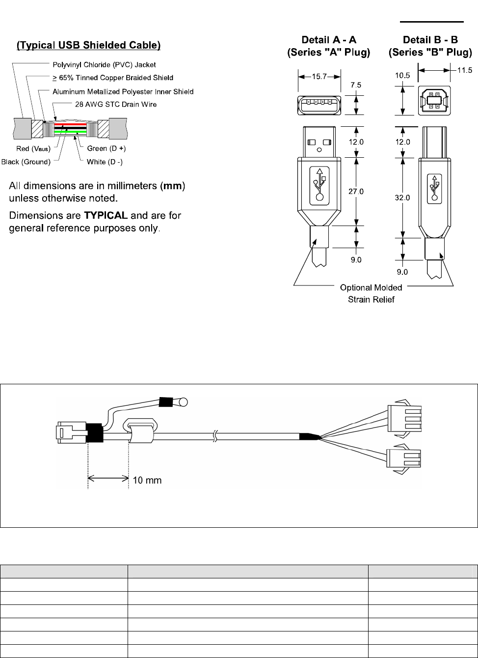
3-5-4 USB2.0 Interface
SRP-270 support the USB (Universal Serial Bus) Serial Communication.
3-5-4(a) Specification
Item Description Remark
Transfer Type • BULK
Data Signal • Bi-direction, Half-Duplex
• Differential Signal Pair (D+ / D-)
Data Format • NRZI Format
• Zero Bit Stuffing after 6 ones
Transceiver
• Differential Receive Sensitivity : 200[mV]
• Differential common Mode Range : 0.8 ~ 2.5[V]
• Single-End Receiver Threshold : 0.8 ~ 2.0[V]
Speed • 12 Mbps
Power • Self-Powered
Cable & Connector • Cable : 5m / 2m
• Connector : B Type
Other • Support USB SPEC V1.1
Table 3-20 USB Specification
3-5-4(b) Signal Description
Pin No. Signal Name Assignment(Color) Function
Shell Shield Drain Wire Frame Ground
1 VBUS Red Host Power : DC5[V] / 500[mA]
2 D- White Differential Data Line
3 D+ Green Differential Data Line
4 GND Black Signal Ground
Table 3-21 USB Pin Description
3-5-4(c) USB I/F Cable
Figure 3-10 USB A-B Type Cable
Rev. 3.02 - 28 -
SRP-270
3-6 Cash Drawer Specifications
3-6-1 Cash Drawer Cable
Ferrite Core : 1 turn (OP-18E : 18.2 x 12.5 x 25.5)
Figure 3-12 Cash Drawer Cable
3-6-2 Cable Connection
Pin No. Description Direction
1 Frame GND -
2 Cash Drawer Driver Signal #1 Output
3 Drawer Open / Close Signal Input
4 +24V -
5 Cash Drawer Driver Signal #2 Output
6 Signal GND -
Table 3-23 Cash Drawer Cable Connection
※Note : +24V is always output through pin 4 during power on.
Rev. 3.02 - 29 -
SRP-270
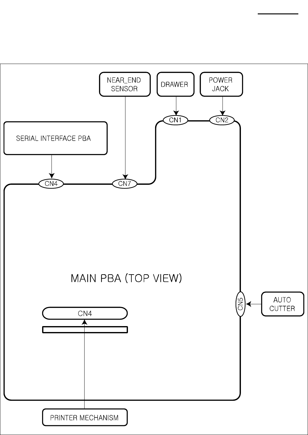
4. Hardware
4-1 Wiring Diagram
[Figure 4-1 Board Wiring Diagram]
Rev. 3.02 - 30 -
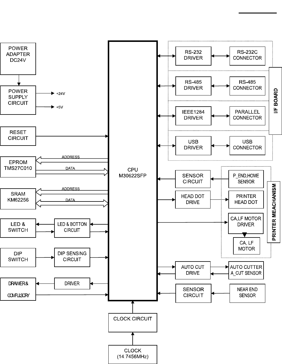
SRP-270
4-2 Block Diagram
[Figure 4-2 Block Diagram]
Rev. 3.02 - 31 -
SRP-270
4-3 Special Circuit Descriptions
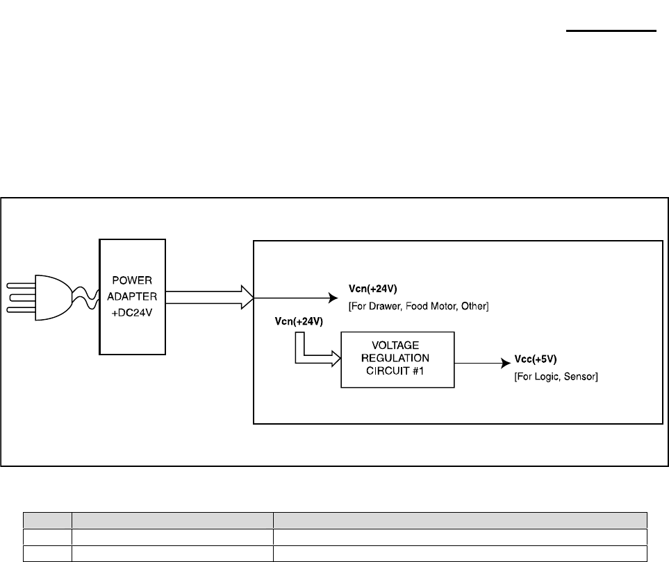
4-3-1 Power Circuit
This system is operated under 110Vac or 230Vac. The power circuit supplies the three differential DC voltage
sources.
[Figure 4-3 Power Block Diagram]
1) Drawer Driving and Feed, Auto Cutter Motor Voltage : +24Vdc
+24VDC is supplied from SMPS. This Voltage is smoothed by capacitors (C1,6,39).
This voltage is used as a Printer Head, Printer Motor, Cash Drawer Solenoid Driving voltage and a source
voltage of the +5V voltage sources.
2) Logic IC Driving Voltage: +5V
+5Vdc Logic driving voltage is produced by the step-down dc-dc converter U1(34063A). That is, U1 produces
rectangular wave. This makes D2 (EK04) and L6 store energy. The voltage is smoothed by C8 (470uF) and
then +5Vdc Logic voltage is produced.
No. VOLTAGE DESCRIPTION
1 +24VDC Cash Drawer Solenoid Driving / Step Motor Voltage
2 +5VDC Logic IC Driving Voltage / Sensor
Rev. 3.02 - 32 -
SRP-270
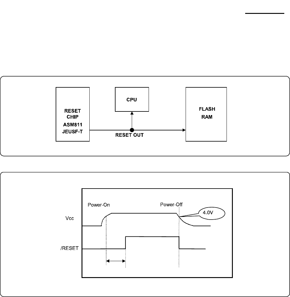
4-3-2 RESET Circuit
Reset signal is a signal in order to start-up CPU under Power-on. Reset circuit uses a reset ICTL7705ACD
(U5). When +5Vdc is fallen under 4.3Vdc by Power-off, reset signal prohibits the system from misoperating
by lowering down to 0V.
[Figure 4-4 Reset Block Diagram]
[Figure 4-5 Reset Waveform]
5ms
Rev. 3.02 - 33 -
SRP-270
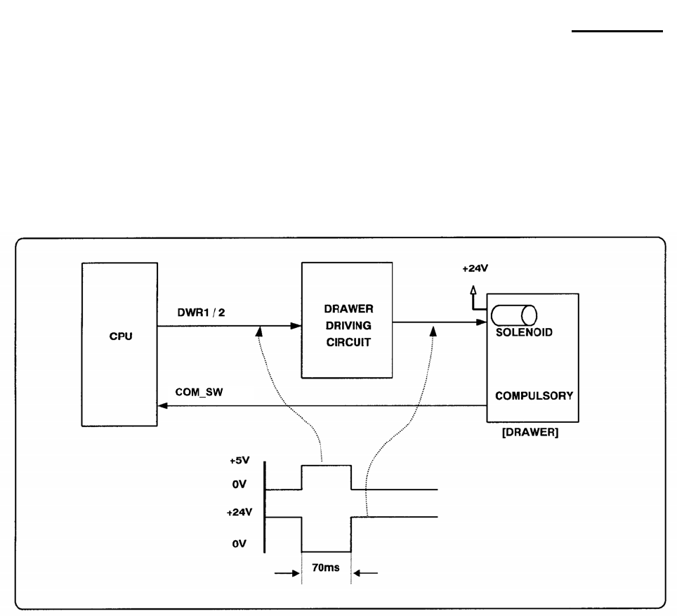
4-3-3 Cash Drawer Circuits
The circuit is used for opening cash drawer and driven by the Q8 (STA471). When its state is high level
signal, Q8 (STA471) drive the solenoid to open the cash drawer. As an optional item, we provide sensor
switch (we call it a compulsory switch) which checks the drawer whether it is opened or not. This sensor
switch turns on for the drawer open condition, and turns off for the other.
Caution: make sure that the Cash Drawer solenoid resistance is more than 20Ω.※
[Figure 4-6 Cash Drawer Block Diagram]

Rev. 3.02 - 34 -
SRP-270
4-3-4 I/F PBA Detect Block Diagram
When the printer is ON, the printer checks what kind of the I/F PBA is installed. After detection, the CPU
specify the I/O port properly. The following is the method of I/F PBA detection.
First, The CPU sends a “I/F Sel “ signal (P7.3) to I/F PBA. The I/F PBA has the three return Signal
(DIPC1~C3).
The CPU recognize the I/F PBA by the value of the three return signal.
I/F PBA DIP_C1 DIP_C2 DIP_C3
RS-232C L L H
RS-485 L H L
IEEE1284 H L L
USB2.0 H H L
No Connection L L L
Rev. 3.02 - 35 -
SRP-270
4-3-5 RS-232C Communication Block Diagram
The CPU is used for serial communication.
And also RS-232C Driver (MAX232), is used to serial communication.
Show following block diagram.
[Figure 4-8 RS-232C Communication Block Diagram]
[Figure 4-9 RS-232C Communication Waveform]
M30622SFP
Rev. 3.02 - 36 -
SRP-270
4-3-6 RS-485 Communication Block Diagram
The CPU is used for serial communication.
And also RS-485 Driver (MAX488), is used to serial communication.
Show following block diagram.
[Figure 4-10 RS-485 Communication Block Diagram]
[Figure 4-11 RS-485 Communication Waveform]
M30622SFP
Rev. 3.02 - 37 -
SRP-270
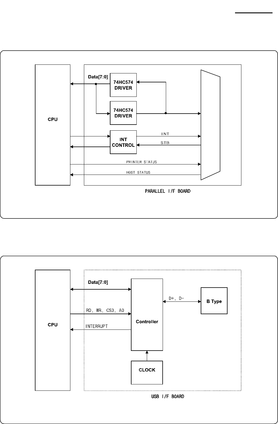
4-3-7 Parallel Communication Block Diagram
The printer support the bidirectional Parallel Interface with Centronics, Nibble, Byte Mode.
The Centronics is Forward and the Nibble, Byte are reverse Mode.
[Figure 4-10 IEEE1284 Communication Block Diagram]
4-3-8 USB Communication Block Diagram
The printer support the USB (Universal Serial Bus). The transfer type of the printer is the BULK.
[Figure 4-11 USB2.0 Communication Block Diagram]
M30622SFP
M30622SFP
USBN9602
48[MHz]
Rev. 3.02 - 38 -
SRP-270
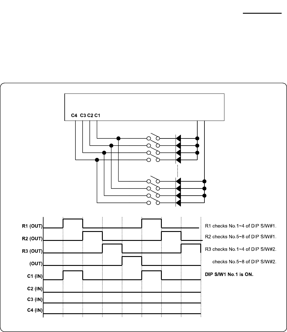
4-3-9 DIP Switch Circuit
The key Board Circuit consist of the scan signal of 4 lines and the return signal of 4-line. The CPU sends
repeatedly and continuously the scan data R1, 2, 3, 5 through P10.0~10.2, P1.1. The DIP S/W information
input in the return signal if the specific DIP S/W is ON Status during the given time. The CPU reads the data
through C1~C4 and analyzes what DIP S/W is ON and performs the selected function.
[Figure 4-12 DIP Switch Block Diagram]
M30622SFP
R1~R3,R5
DIODE(MMBD6050L)
R5 R5

Rev. 3.02 - 39 -
SRP-270
5. Disassembly and Assembly
5-1 General Precautions on Disassembly
This chapter describes the Disassembly and Reassembly procedures for the Printer of SRP-270 Series.
This Printer contains electronically sensitive device. Use caution when handling any component.
Whenever servicing the machine, you must perform as follows:
1. Disconnect the DC power jack of Adapter from the Printer before Disassembling.
2. Use a flat and clean surface.
3. Replace only with authorized components.
4. Do not force to remove plastic-material components.
5. Make sure all components are in their proper position.
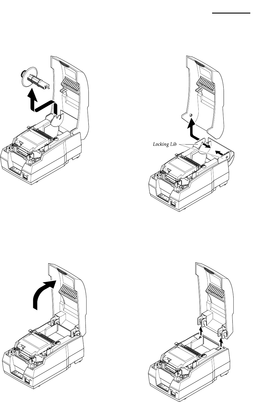
5-2 Plate Bottom
1. Remove four screws securing the Plate Bottom.
Separate the Plate Bottom from the Lower Case.
3. Unplug Auto Cutter wire and FPC Cable from
the Main PCB.
2. If you want to remove the PCB Cover, remove
screw securing, as shown below.
Rev. 3.02 - 40 -
SRP-270
5-3 Cover Assy (SRP-270D Type)
1. Open the Cover Assy and take out the Spool
Winding, as shown below.
2. Push the locking lib to the direction of arrow
and remove the Cover Assy, as shown below.
5-4 Cover Assy (SRP-270A & SRP-270C Type)
1. Open the Cover Assy. 2. Pull the Cover Assy upward and remove it.
Rev. 3.02 - 41 -
SRP-270
5-5 Case Upper Assy (SRP-270A & SRP-270C Type)
1. Open the cover Assy. 3. Separate the Case Upper from the Case
Lower.
2. Remove four screws.

Rev. 3.02 - 42 -
SRP-270
5-6 Case Upper Assy (SRP-270D Type)
1. Push the locking lib to the direction of arrow and
remove the Cover Assy, as shown below.
2. Remove four screws securing the Case Upper.
Separate the Case Upper from the Case Lower.
5-7 Printer Assy (SRP-270A & SRP-270C Type)
1. Before you disassembly the Printer
Assy, you should remove :
- Plate Bottom (see Chapter 4-2)
- Cover Assy (see Chapter 4-3 & 4-4)
- Case Upper Assy (see Chapter 4-6)
2. Remove two screws securing the Printer Assy.
Separate the Printer Assy from the Case Lower.

Rev. 3.02 - 43 -
SRP-270
5-8 Printer Assy (SRP-270D Type)
1. Before you disassembly the Printer Assy, you
should remove :
- Plate Bottom (see Chapter 4-2)
- Cover Assy (see Chapter 4-3 & 4-4)
- Case Upper Assy (see Chapter 4-6)
2. Remove the Spool Gear and Belt, as shown
below.(SRP-270D Type)
3. Remove two screws securing the Printer Assy.
Separate the Printer Assy from the Case Lower.
5-9 Auto Cutter Assy
1. Before you disassembly the Auto Cutter Assy, you
should remove :
- Plate Bottom (see Chapter 4-2)
- Cover Assy (see Chapter 4-3 & 4-4)
- Case Upper Assy (see Chapter 4-6)
- Printer Assy (see Chapter 4-7 & 4-8)
2. Remove two screws securing the Auto Cutter
Assy. Separate the Auto Cutter Assy from the
Printer Assy, as shown below.
3. Before you reassembly the Auto Cutter Assy,
you should set up the Belt and Hinge.
Rev. 3.02 - 44 -
SRP-270
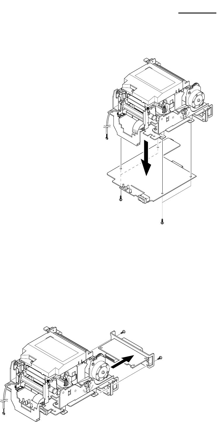
5-10 Main PCB
1. Before you disassembly the Main PCB,
you should remove :
- Plate Bottom (see Chapter 4-2)
- Cover Assy (see Chapter 4-3 & 4-4)
- Case Upper Assy (see Chapter 4-6)
- Printer Assy (see Chapter 4-7 & 4-8)
2. Remove four screws securing the Main PCB.
Separate the Main PCB from the Main Frame.
5-11 Interface Board Assy
1. Before you disassembly the Interface Board Assy, you should remove :
- Plate Bottom (see Chapter 4-2)
- Cover Assy (see Chapter 4-3 & 4-4)
- Case Upper Assy (see Chapter 4-6)
- Printer Assy (see Chapter 4-7& 4-8)
2. Remove two screws and take out the Interface Board Assy, as shown below.

Rev. 3.02 - 45 -
SRP-270
6. Alignment and Adjustments
6-1 Printer Adjustment
When assembling this printer, be sure to refer to the required adjustment procedure.
To ensure normal operation of the printer after disassembly or replacement of a Component for maintenance
or repair. Be sure to perform along to the required method.
* Adjustment of Head gap
Adjustment
Step Description Points in Adjustment
1
2
3
4
• Rotate Gear lst Reduction to move the Head unit
to L side.
• Insert the thickness gauge between Head unit and
Platen, then rotate the Ad.
Level L and adjust the gap.
• Move the Head unit then check if the proper
gap from R side center has been achieved.
• If Head gap is not proper, adjust Head gap by
rotating Ad.Lever R.
- Appropriate gap: 0.50~0.60mm
- In order to make the gap narrow
(wide), turn Ad.
Lever to mark ’-(+)’
- If gap is not correct, repeat once
more.
(Replacement of Head unit)
Follow below steps for replacing Head unit
1. Loosen the Ribbon frame
2. Disassemble the Head unit from the Head Carriage and take out the Head FPC from the connector of
PCB Assy.
4. Replace the Head unit and assemble, according to the order of sub Aassy-1
5. After assembling, adjust the gap as above “Adjustment” indicates.
6. Assemble the Ribbon Frame.

Rev. 3.02 - 46 -
SRP-270
7. Troubleshooting
7-1 Power Problem
• Check the Power Out on SMPS.
• Check the Fuse.
• Check the related Pattern.
• Check the IC34063.
7-2 System Problem
• Check the Reset part (IC & Pattern)
• Check the Clock on FS741 (14.7456MHz)
• Check the Adr/Data line Pattern
7-3 Printer Problem
• Check the Feed Motor Signal on CPU
• Check the Feed Motor Block on PCB (STA471, Step Motor Connection)
• Check the Carriage Motor Signal on CPU
• Check the Carriage Motor Block on PCB (STA471, Step Motor Connection)
• Check the Ribbon Select Signal on 74HCT574 (U22)
• Check the Ribbon Block on PCB (STA471, Connection)
• Check the Auto Cutter Signal on 74HCT574 (U22)
• Check the Auto Cutter Block on PCB (TA8428K, Connection)
• Check the Near-End, Home Sensing Signal on Main PBA.
• Check the Sensing Block. (Sensor, Harness)
• Check the Head Trigger Signal, Head Signal on CPU.
• Check Dot Printing Block on Main PBA. (STA471, 74HCT05, Connection)
7-4 Cash Drawer Problem
• Check the Drawer Connector & Harness.
• Check the Drawer Signals on 74HCT574.
• Check the Drawer Block on Main PBA (STA471, Connection).
7-5 DIP S/W Problem
• Check the Output Signal (DIP R1~4)
• Check the Diode.
• Check the Input Signal (DIP C1~C4)
• Check the related Circuit & Pattern
7-6 RS232 Problem
• Check the connection of the RS-232C CONN and Other side.
• Check the I/F Cable whether it is open or short.
• Check the Txd, Rxd Pin on CPU.
• Check the MAX232 Driving Chip and related Circuit on I/F PBA.
• Check the connection of the H/W handshaking Line and Other side (DTR/DSR)
7-7 RS485 Problem
• Check the connection of the RS-485 Connector and Other side.
• Check the I/F Cable whether it is open or short.
• Check the TXD, RXD Pin on CPU.
• Check the MAX488 Driving Chip and related Circuit on I/F PBA.
• Check the connection of the H/W handshaking Line and Other side (DR1,2/CS1,2)
• Check the Voltage Level of each Line.

Rev. 3.02 - 47 -
SRP-270
7-8 IEEE 1284 Problem
• Check the Control Line (CS3, WR, RD).
• Check the 1284 Control Line and Status Line.
• Check the Signal of ICs (U3, U6, U5)
• Check the related Circuit and Pattern on I/F PBA.
• Check the 1284 Control, Status Data Line.
7-9 USB Problem
• Check the Control Line & Signal. (CS3, RD, WR, INT)
• Check the Data Line & Signal.
• Check the Connector (34P)
• Check the Clock (48MHz)
• Check the related Circuit and Pattern on I/F PBA & Main PBA.
• Check the D+ whether it is Pull up to V3.3.
• Check the USB Cable whether it is open or short.
Rev. 3.02 - 48 -
SRP-270
8. Appendix (Spec of SMP-710/710N)
8-1 Specifications
8-1-1 Printing specifications
Item Description
Printing method serial impart dot-matrix
Head wire configuration 9-pin serial type
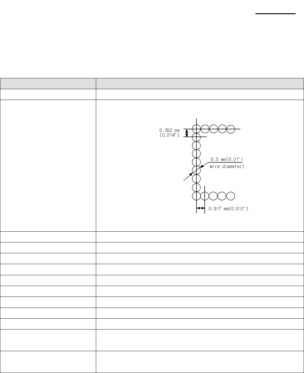
Dot pitch 0.352mm(1/72")
Dot wire diameter 0.3mm(0.01")
Printing direction Bidirectional with logic seeking
Printing width 63.5mm(2.5")
Line feed 4.233mm(1/6") (default setting)
Paper feed method Friction feed
Paper feed speed Approximately 6.2 inches/second (during continuous paper feeding)
Characters per line See the table on the next page
Characters per inch See the table on the next page
Total dot count
(horizontal direction)
7×9 font (400 half-dot positions per line)
9×9 font (400 half-dot positions per line)
Print speed Approximately 4.6 lines/second (40 columns, 16cpi)
Approximately 8.4 lines/second (16 columns, 16cpi)
NOTE: If the print duty ratio is too high, the operation of the print※ head is stopped by the duty limit.
In such circumstances, the print speeds shown above cannot be guaranteed.
cpi=characters per inch.
Rev. 3.02 - 49 -
SRP-270
8-1-2 Character specifications
8-1-2-1 Character sets
Item Description
Alphanumeric 95
International 32
Graphics 128×7 pages
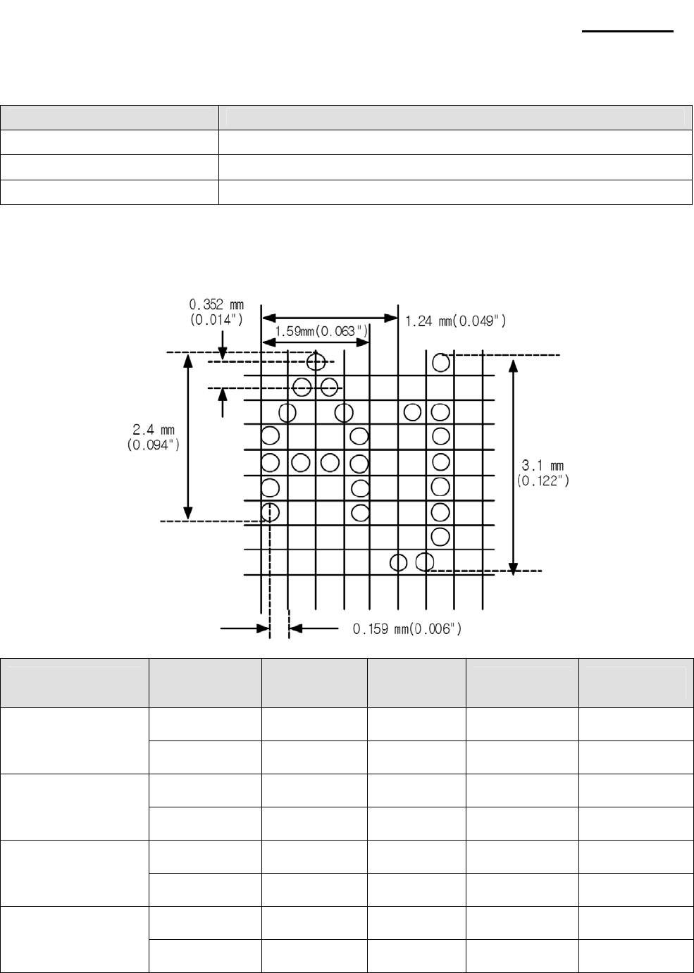
8-1-2-2 Character structure
* 7×9 with 400 half-dot positions per line.
* 9×9 with 400 half-dot positions per line.
Character structure
Horizontal × Vertical
Character
structure
Character Set
Character
Dimensions
W x H
Dot spacing
Between
Characters
Characters Per
Line (cpi)
Characters Per
Inch (cpi)
ANK 1.2×3.1 mm
(.047×.122") 3 half dots 40 16
7 × 9
Graphics 1.7×3.1 mm
(.070××.122") 0 40 16
ANK 1.6×3.1 mm
(.063×.122") 3 half dots 33 13.3
9 × 9
Graphics 2.0×3.1 mm
(.079×.122") 0 33 13.3
ANK 1.2×3.1 mm
(.047×.122") 2half dots 42 17.8
7 × 9
Graphics 1.6×3.1 mm
(.063×.122") 0 42 17.8
ANK 1.6×3.1 mm
(.063×.122") 2half dots 35 14.5
9 × 9
Graphics 1.9×3.1 mm
(.075×.122") 0 35 14.5
NOTE: The default font is 7×9; the dot spacing between characters is either 3 half dots or 2 half ※
dots, depending on programming.
Rev. 3.02 - 50 -
SRP-270
8-1-3 Paper specifications
Item Description
Paper types Paper roll: Platen paper or pressure-sensitive paper
Paper roll width 76±0.5mm (2.99±0.20")
Paper roll maximum diameter Ø83mm(3.27")
Paper roll core Unless there is an optional near-end detector, you cannot use a paper roll
with the core and paper glued together.
Normal paper Thickness: 1 sheet: 0.06 to 0.085 mm(.0024 to.0034")
Weight: 52.3 to64g/m2(13.9 to 171b) (45 to 55kg/1000 sheets/1091×788)
Pressure-sensitive paper
Original sheet + up to 1 copy sheet
1 sheet thickness: 0.05 to 0.08mm(.0020to.0031")
Total thickness: 0.2mm(.0078")or less
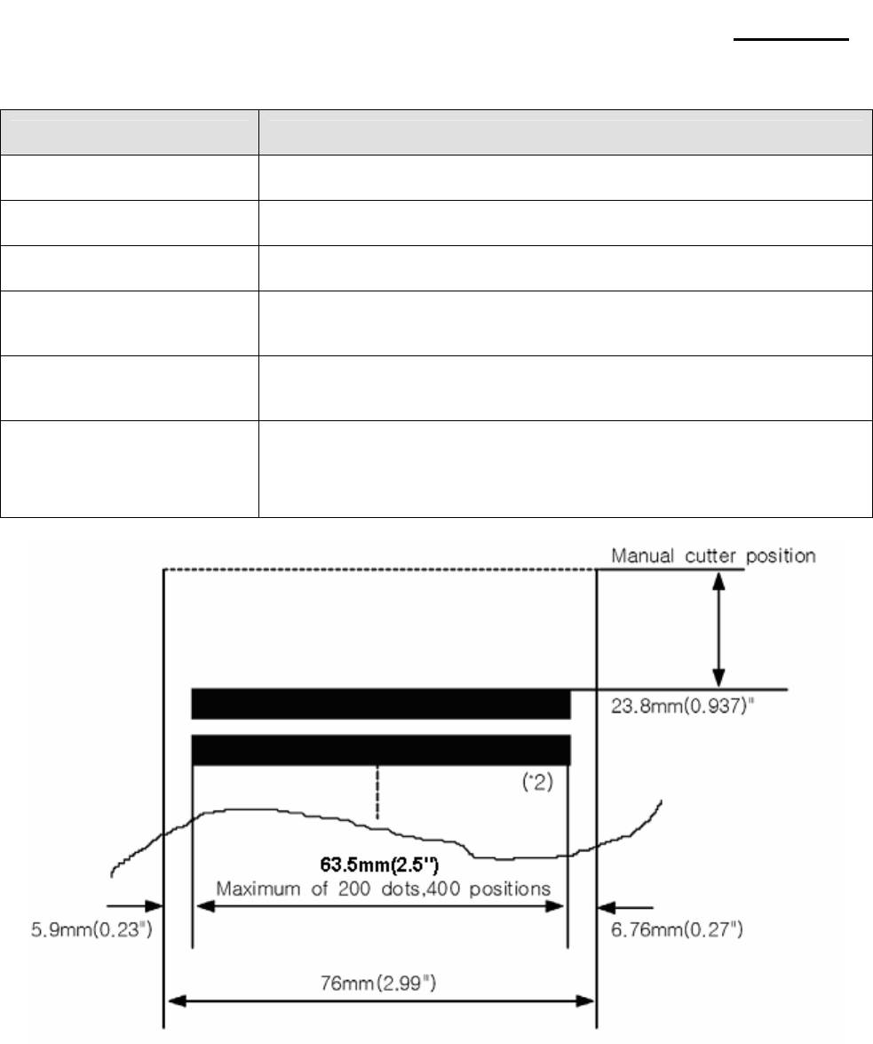
(*1) This dimension shows the distance from the manual cutter to the print position.
(*2) Values for the printing area are calculated (between dot centers) with the wire diameter{0.29mm(.011")}
Rev. 3.02 - 51 -
SRP-270
8-1-4 Ribbon Cassette specifications
Compatible Model Color Ribbon life ("1)
ERC-38 (B) Black 3 million characters {with continuous printing at 25 (77°F)}℃
ERC-38 (B/R) Black and Red Black: 1.5million characters {with continuous printing at 25 (77°F)}℃
Red: 750,000 characters {with continuous printing at 25 (77°F)}℃
("1) Ribbon life is based on the following conditions:
Character font: 7×9 font (with descenders)
Print pattern: ASCII 96-character rolling pattern. See the specification published by SMP-710/710N
for the print pattern example.
NOTE: Malfunctions and other problems may occur if a ribbon cassette other than the specified ※
one is used.
8-1-5 Environmental specifications
Item Description
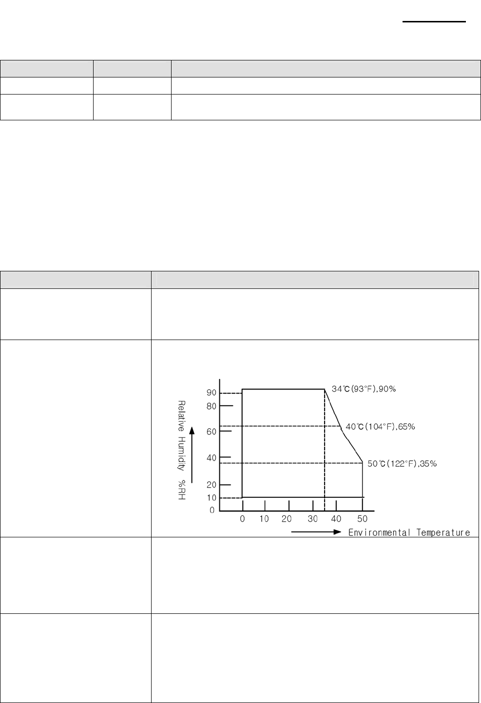
Temperature
Operating: 0°to 40 (32°to 1℃04°F)
At 34 (93°F)or higher, there are humidity restrictions;℃
See the figure below.
Storage: -5°to 50 (℃23°to 122°F), except paper and ribbon
Humidity
Operating: 30% to 80% RH(non-condensing)
Storage: 10% to 90% RH(non-condensing),except paper and ribbon
Vibration resistance
* When packed
Frequency: 5 to 55Hz
Acceleration: 5G
Sweep: 10 minutes (half cycle)
Duration: 1 hour
Directions: x, y and z
Impact resistance
* When packed
Package: SMP-710/710N standard package
Height: 60cm(23.62")
Directions: 1 corner, 3 edges, and 6 surfaces
* When unpacked
Height: 5cm(1.97")
Directions: Lift one edge and release it(for all 4 edges)

Rev. 3.02 - 52 -
SRP-270
8-1-6 Reliability
Item Description
MCBF This is an average failure interval based on failures relating to wear out and random failures up
to the life of 18 million lines.
8-1-7 Main Unit specifications
Item Description
Type 4-phase, 48-polarity, PM-type stepping motor
Drive voltage 24 VDC±10%
Winding resistance 10Ω±1Ω at 25 (77°F), per phase℃
Paper
Feed
Motor
Current consumption Average: 400mA at 24 VDC, 25 (77°F), 570mA maximum℃
Type 4-phase, 48-polarity, PM-type stepping motor
Drive voltage 24 VDC±10%
Winding resistance 10Ω±1Ω at 25 (77°F), per phase℃
Carriage
Motor
Current consumption Peak: 1.5 A in maximum
Average: 400mA at 24 VDC, 25 (77°F), 570mA maximum℃
Number of solenoids 9
Winding resistance 9.5Ω±10% at 25 (77°F), per phase℃
Print
Head
Unit Drive voltage 24 VDC±10%
Type Photo sensor
Voltage 5 VDC±5%
Home
Position
Sensor Output level LOW when the carriage home position is detected.
Rev. 3.02 - 53 -
SRP-270
8-1-8 Electrical specifications
8-1-8-1 The explanations of the circuit operations
1) Head Carriage Step Motor
- It rotates and moves the Dot Head by using the several gears and synchronous belt
- Print Speed : 4.6 Line/Sec
- This step motor is control by constant current method.
So, current flows two red line of step motor is Max.560㎃
- This step motor is control by SMA7029M (Recommended)
2) Paper Feed Step Motor
- It is used when the paper is fed.
- The characteristics of step motor is as same as head carriage step motor
3) Home Sensor
- It detects the head position
- It decides the start point of printing
4) Solenoid
- It plays part in exchanging printing color (red → black)
5) Head
-It plays part in printing a character (Axiohn Co.)
8-1-8-2 Circuit Block Diagram
8-1-9 Mechanisms specifications
This printer consists of 5 mechanisms;
Head feeding Mechanism. Printing Mechanism. Paper Feeding Mechanism. Detector Mechanism, Ribbon
Mechanism. How is the external view of SMP-710/710N Impact dot matrix printer as shown. For details on the
operating principles and handling of each of the mechanisms, refer to "Principle of Movement" in section 8-1-
10 and "Handling, Maintenance and Repair" in 8-2.
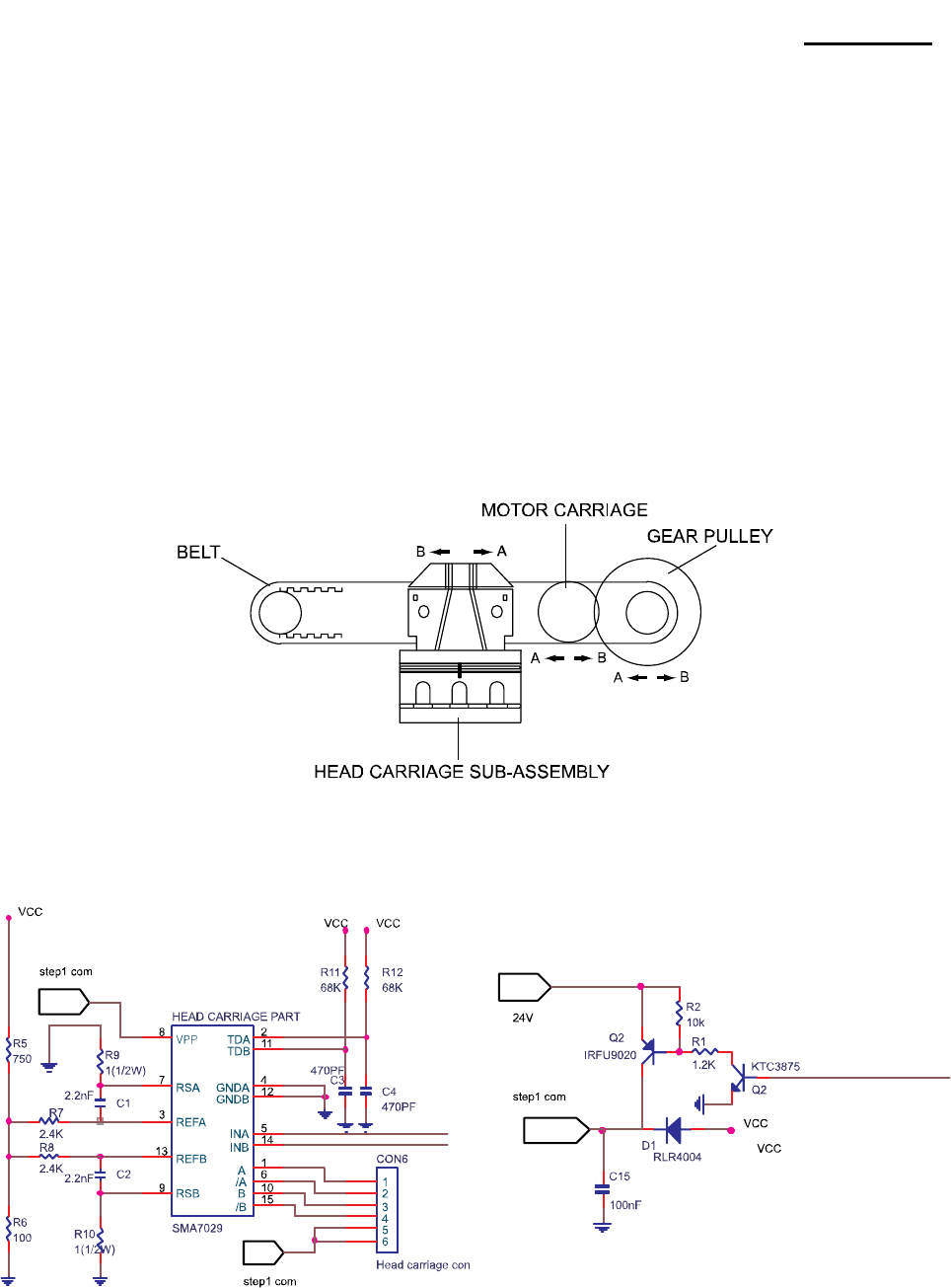
Rev. 3.02 - 54 -
SRP-270
8-1-10 Principle of Movement
8-1-10-1 Head Feeding Mechanism
This printer is using DC24V PM Type Stepping motor.
As shown in figure the motor section consists of the motor. Motor speed control IC, motor drive/brake circuit
and motor speed interface.
When the carriage motor is driven and the carriage motor gear is moved in the direction of arrow B(forward
rotation), the rotational power is conveyed to the belt drive pulley, then the belt. Next the carriage sub
assembly, which is fixed to the belt, moved in the direction of arrow B.
When the carriage motor gear is rotated in the direction of arrow A (reverse rotation), the carriage sub
assembly is moved in the direction of arrow A.
Rev. 3.02 - 55 -
SRP-270
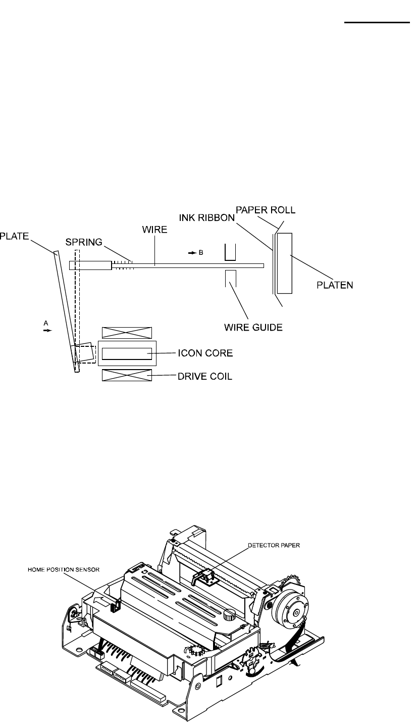
8-1-10-2 Printing Mechanism
When the specified print head drive pulse is input to the drive coil, the iron core is magnetized, and the
actuating plate is pulled in the direction of arrow A.
This action pushed the wire toward the platen, When the wire strike s the ink ribbon and paper against the
platen(*), a single dot is printed.
When the energizing of the drive coil is completed, the wire and actuating plate are re turned to the standby
position by the wire return spring and actuating plate spring.
(*)The "platen" is the portion of the base paper feed Assy being struck by the wires during printing.
8-1-10-3 Detection Mechanism
The detection mechanism unit consists of the home position detection, paper detection.
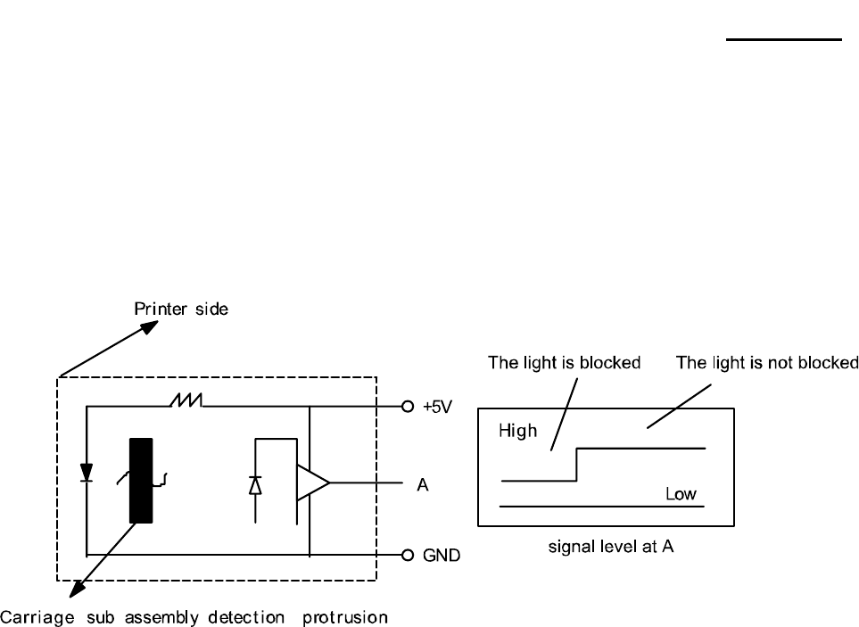
Rev. 3.02 - 56 -
SRP-270
8-1-10-4 Home Position Detection Mechanism
The home position detection mechanism consists of the detection protrusion at the left side of the carriage
sub assembly and the sensor sub assembly at the left side of the base frame. It determines the home
position, identifies the carriage position, and detects carriage sub assembly operation errors.
The sensor sub assembly consists of an LED and photo transistor. When the carriage sub assembly moves,
the detection protrusion passes between the LED and photo transistor and blocks the optical axis of the
photo transistor, changing the output level of the photo transistor.
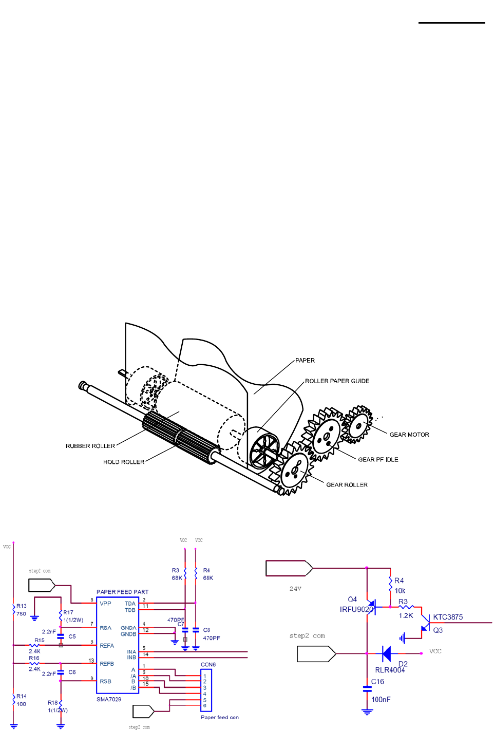
Rev. 3.02 - 57 -
SRP-270
8-1-10-5 Paper Feeding
Paper feeding is performed by conveying the paper feed motor` s rotational power from the paper feed motor
gear through the paper feed reduction gear, paper feed gear, and paper fed roller.
Since the paper feed roller and paper hold roller are pressed together, paper advances to the top of the
paper feed frame assembly because of the friction between the rubber of the paper feed roller and the paper
hold roller.
As shown in Figure, Paper feeding mechanism consists of Rubber Roller Hold Roller Assy, Step Motor, Gear
Step M/T idle, Gear MF and Gear M/F Idle The paper feeding operation can be selected by controlling the
Step Motor. For detail explanations of paper feeding operation, refer to "SPECIFICAT10NS
for SMP-710/710N".
Paper feeding is made as follows; As Step Motor set turning by electric signal, Gear Rubber Roller comes
into turning, passing Gear Step M/T Idle for Shaft Roller is pressed to rubber Roller by Spring Roller, Paper is
feed by friction A min. Pitch is 1/144".
Under condition Step Motor stops, turning Gear MF to direction of arrow or to 1, he contrary, and can feed or
back feed as paper wants.
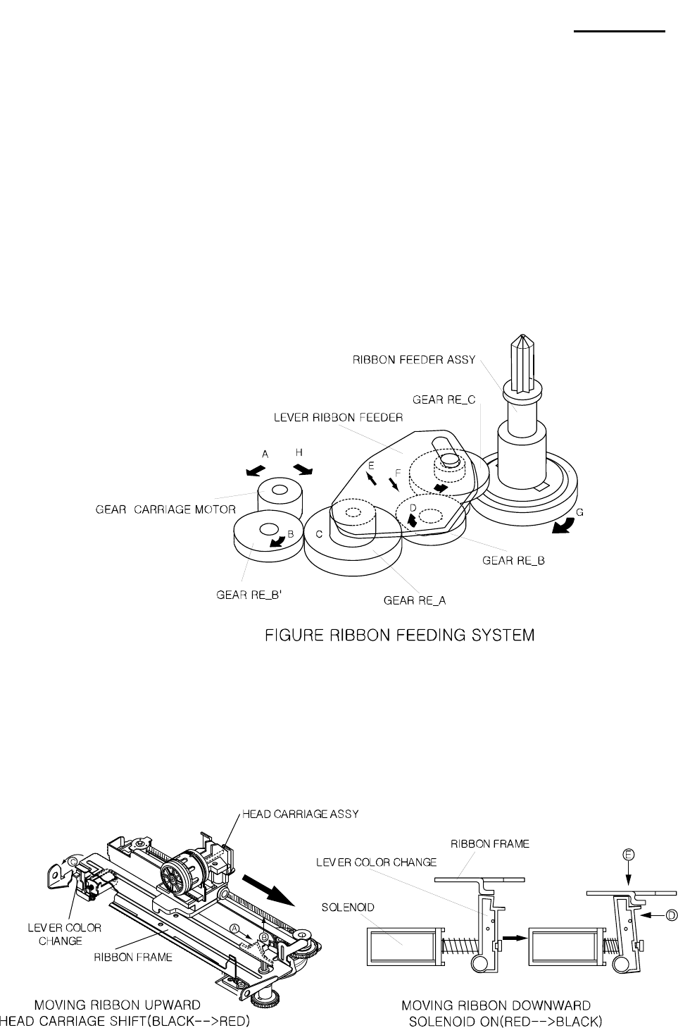
Rev. 3.02 - 58 -
SRP-270
8-1-10-6 Ribbon feeding
When the carriage motor rot ate s counter clockwise and the carriage motor gear rotates in the direction of
arrow A, the Gear Reduction B' Gear Reduction A Gear Reduction B, rotate in the directions of arrows B,
and C, B' respectively.
This causes the Lever Ribbon Feeder Assy to move in the direction of arrow E, rotating round the Gear
Reduction A shaft in the center, until the Gear Reduction B goes in with the Gear Reduction C.
Since the Gear Reduction C and the ribbon feeder are always engage d, the ribbon feeder rotates in the
direction of arrow G.
When the carriage motor rotates in the reverse direction and the carriage motor gear rotates in the direction
of arrow H, the Lever Ribbon Feeder Assy moves in the direction of arrow F, disengaging the Gear reduction
B from the Gear Reduction C.
Therefore, the ribbon feeder Assy rotates in the direction of arrow G only when the carriage motor rotates
counterclockwise.
Then the ribbon feed and ribbon hold rollers in the ribbon cassette, which are engaged with the ribbon feeder
Assy, rotate and the ribbon is feed.
* Operation of Color change
Color change system consists of Ribbon feeding Mechanism in section 8-1-10-6 and Ribbon Shifting
Mechanism.
Shifting Mechanism on Ribbon consisted of Head carriage Assy, Ribbon Frame, Lever color change,
solenoid Assy as shows in figure.

Rev. 3.02 - 59 -
SRP-270
* Ribbon shifting operation
Ribbon shifting action is as follows.
As the Carriage Motor rotates clockwise, Head carriage Assy moves from left to right. When you'd like to
change from red color to black color you should shift Head carriage Assy as shows in figure timing chart.
Delivers to Gear HF-1, and turns to direction of arrow wit Lead Cam.
At this moment, if not energized in Solenoid, Solenoid Lever and Shift cachet are not moved, and so Shift
Cam does not turn, and Ribbon Frame is not in Shift Up/Down.
As Solenoid moves energized, Solenoid lever goes down and turns Shift Cam which snatches with moving
Shift cachet under stop. Shift Cam, along Top/Bottom makes to Shift Up/Down of Ribbon Frame and printing
color is printed by Black/Red. Moving Shifting is up to energization and control of Solenoid.
[ Description of Timing chart.1 ]
14Step(28T)①
- Head carriage step motor moves left(14step) after covering the home sensor
- The maximum distance of head tip to move left is 18step, so we can make room for moving space of
4step, exactly 1.2696 mm
This area is consisted of 3 region②
(Accelerating area of left side[30T] + constant speed area[6T] + vertical alignment adjustable time[3T])
400T (printing area, when printing 40 characters of 7×9 font, space between one character and③
another one is 3T)
421T(printing area + decelerating area of right side[24T])④
- Printing area includes part of right side area
24Step ⑤- Paper feeding area
24T ⑥- Distance until outing of head pin when printing from right to left
400T ⑦- Printing area
436T ⑧- Printing area + decelerating area of right side
The start position of head carria⑨ge tip
On uncovering of home sensor⑩
When outing the first head pin⑪
When paper is feed⑫
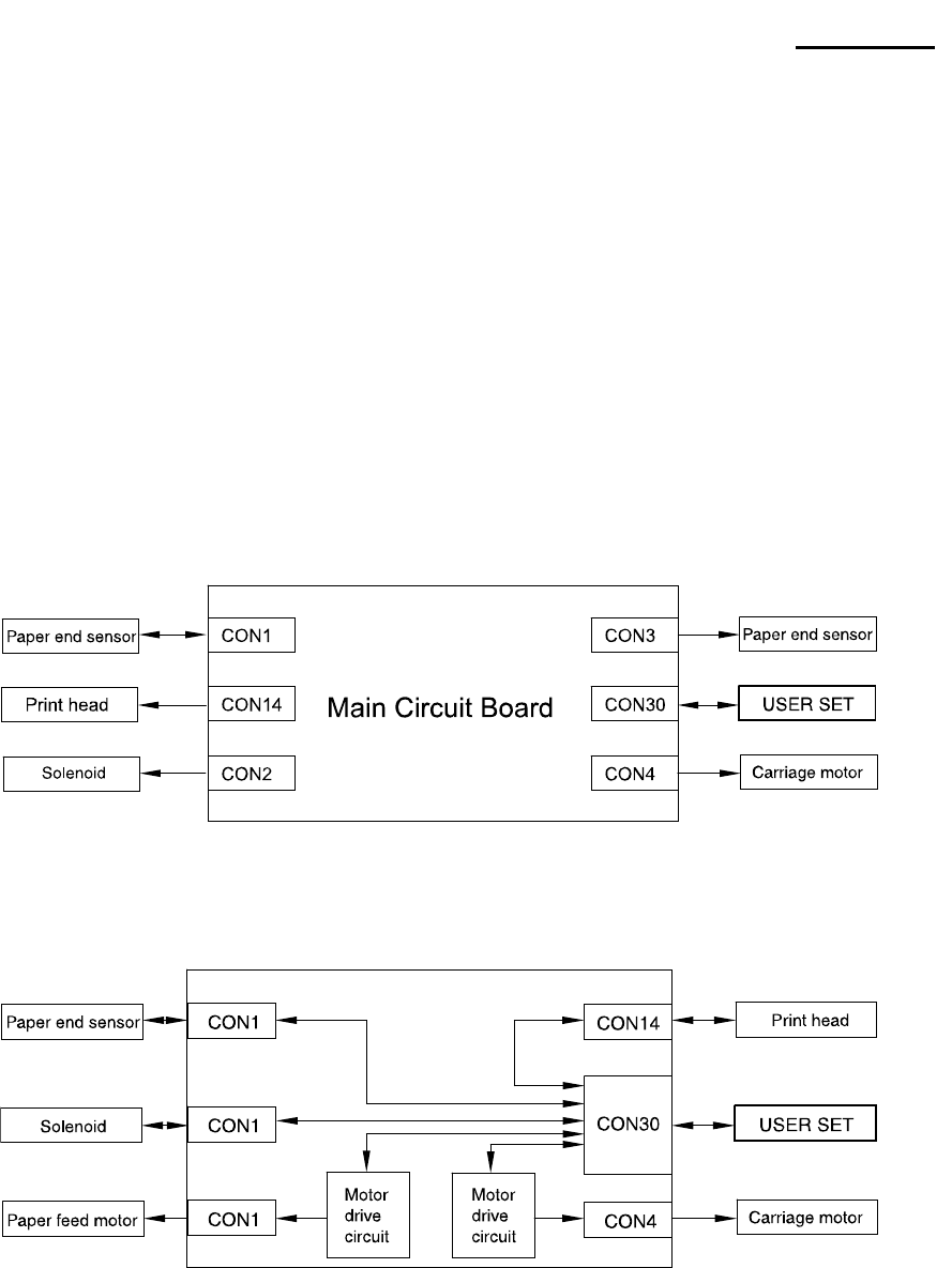
Rev. 3.02 - 60 -
SRP-270
[ Description of Timing chart.2 ]
When head carriage step motor stops(left →⑬ left)
The start position of head carriage step motor from right to left⑭
When fir⑮st outing of head pin from right to left
When last outing of head pin from right to left and when starting line feedⓐ
When ending of printing from fight to leftⓑ
The start position of second printing from left to rightⓒ
Solenoid on time(unlocking coloⓓr-change printing) : 24ms
When head carriage tip covers the home sensorⓔ (after printing from right to left)
* Electrical Circuit Operation Principles (Hardware Configuration)
[ Component connection diagram ]
The electrical circuitry of the printer consists of the main circuit board and the interface circuit boards.
The figure below is a component connection diagram of the electrical circuitry.
[ Circuit board block diagram ]
The figure below illustrates the circuit block diagram for the printer.
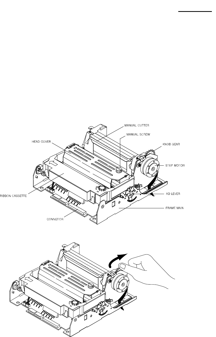
Rev. 3.02 - 61 -
SRP-270
8-2 Handling the Printer
8-2-1 Precautions on Printer Handling
8-2-1-1 Precautions on transport
1) When trans porting this printer. It’s proper handling method is to support both side of Frame main with
both hands.
2) When trans porting this printer. never grasp it by Ribbon cassette case, PCB Connector , and Solenoid
Assy or other such parts.
3) Never expose the printer to impact by dropping or striking it.
4) Take special care that no foreign matter contacts the PCB at the bottom of the printer.
8-2-1-2 Precautions on storage
1) Avoid storage in locations exposed to excessive dirt or dust, direct sunlight or excessive moisture.
2) In case of long- term storage, place the printer into a polyethylene bag after wrapping it in anti- rust paper,
then store it in a dry location.
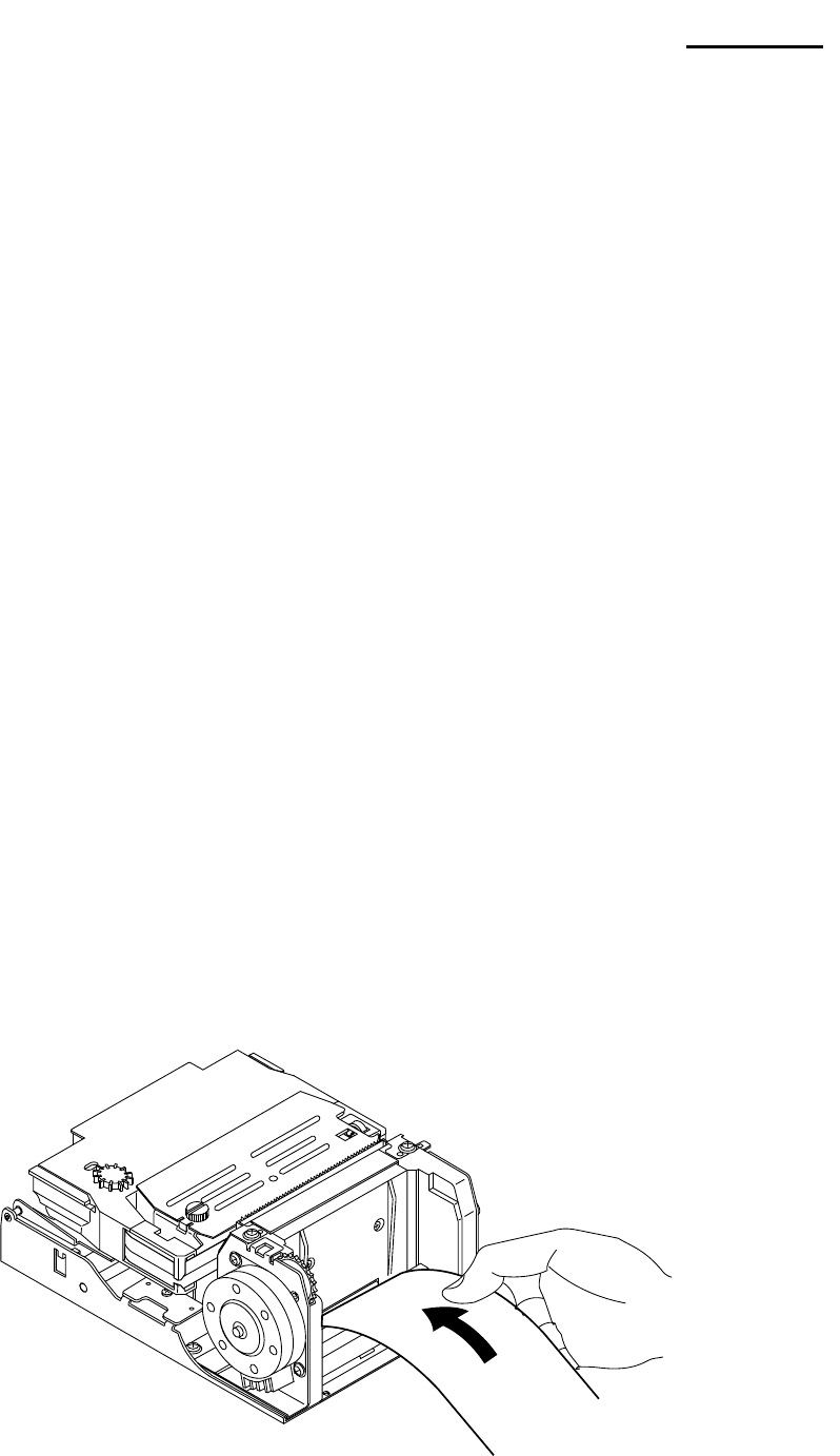
Rev. 3.02 - 62 -
SRP-270
8-2-1-3 Precautions on use
1) Since this printer employs magnetic substance (Motor, Solenoid), avoid using it in locations exposed to
excessive iron filings, dirt, dust or other foreign particles.
2) Never perform a printing operation without the paper and ribbon installed.
3) The printer must be installed on a level surface.
4) When installing this printer, be sure to us e a buffer of rubber or other similar material between the
mounting brackets of the printer and the printer itself (to prevent vibrations caused by printing or paper
feeding and to avoid increased reverberations)
5) For the mounting holes of the printer, be sure to us e the round or oblong holes.
6) Because the PCB is at the bottom of the printer, take care that there is no contact between its parts and
mounting base and that no foreign matter contacts the board.
7) If end mark on Rolled paper appears. Replace the Rolled paper.
8-2-2 Paper Setting Procedures (Insertion/Removal)
Make sure to always use only the paper types prescribed in the SMP- 710/710N Specifications.
8-2-2-1 Inserting Rolled Paper
1) As shown in figure, cut straight the leading edge of rolled paper.
2) After the leading edge of paper goes through Paper Guide, slide the paper until it reaches the Rubber
Roller and Hold Roller.
3) In order to pas s the leading edge of paper between Rubber Roller and Hold Roller, rotate Gear Knob in
the arrow direction.
NOTE: Never perform paper insertion without carefully following the above precautions, because ※
such handling may result in defective paper feeding or paper jams.
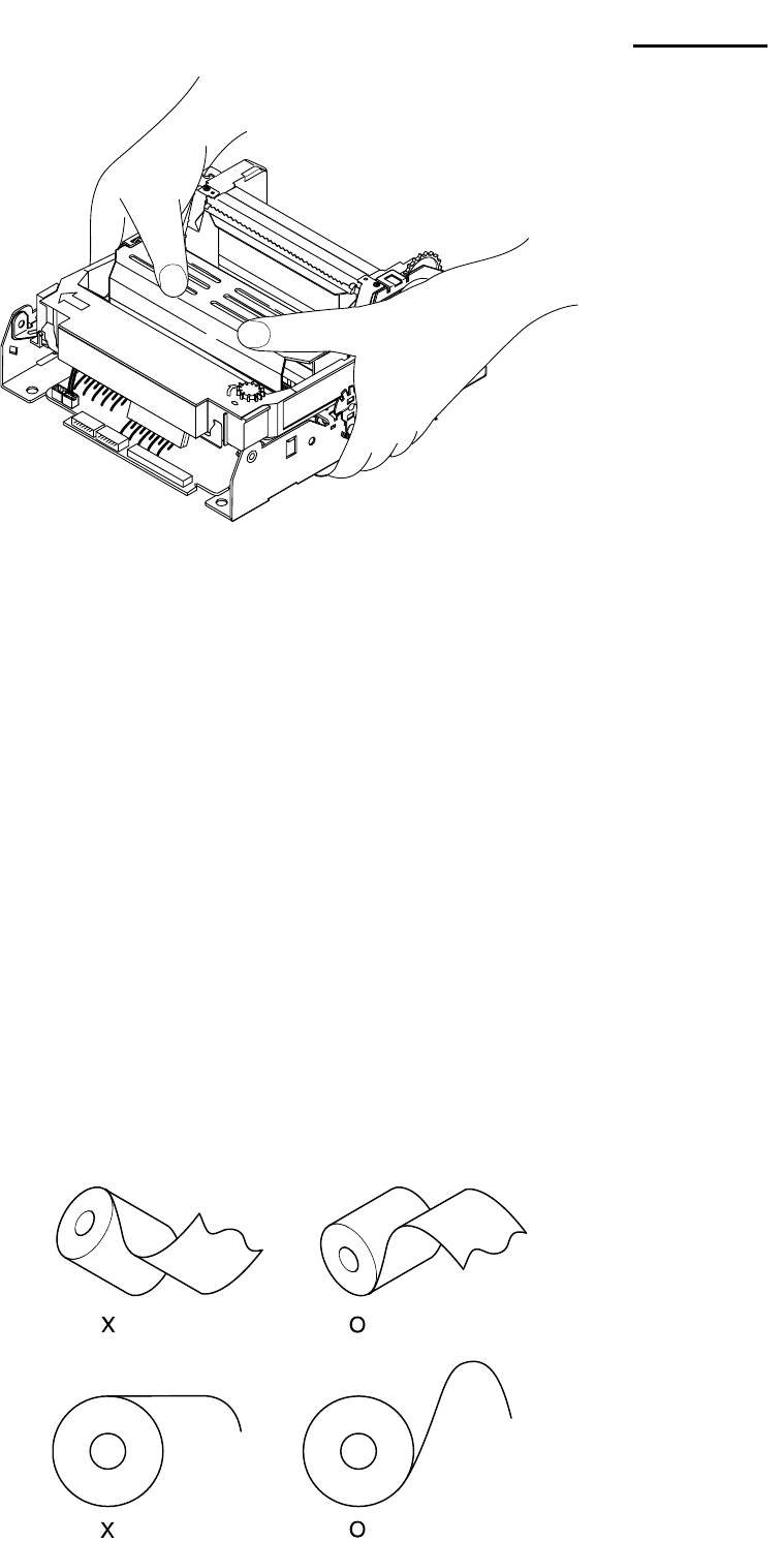
Rev. 3.02 - 63 -
SRP-270
8-2-2-2 Precautions on Paper Insertion
1) After cutting the edge of paper straight as shown in figure insert the paper.
Which is described on next figure.
2) Insert the paper straight into the paper entrance section.
3) The end of the paper which is crinkled and bended, should not be inserted.
4) Make sure that the rolled paper tape is ripped off and discarded before inserting into the printer.
8-2-2-3 Precautions on paper removal
Cut the paper behind Bas e Paper Feed Assy.
8-2-2-4 Paper removal must be performed using one of the four method below
* Remove method by manual
1) Back feed the paper by rotating Gear Knob to contrary arrow direction manually and remove the paper.
2) After Feed the paper by rotating Gear Knob to arrow direction cutting paper in backside Base Paper
Feed Assy, and remove the paper.
* Remove method by automatically
1) Back feed the paper by using electrical operation (by paper back-feed button), then remove the paper.
2) After cutting paper in backside paper guide Assy, feed the paper by using electrical operation (by paper
back feed button), then remove the paper.
NOTE: Never perform paper removal without carefully following the above precautions , because ※
such handling may result in defective paper feeding or paper Jams.

Rev. 3.02 - 64 -
SRP-270
8-2-3 Ribbon Cassette Installation
The Ribbon Cassette use must conform to the standards prescribed in the Specifications.
Never use non-standard types, because such use may result in such trouble as the malfunction of printing
quality.
8-2-3-1 Ribbon Cassette Installation
Procedure for installing the Ribbon Cassette as shown figure.
1) By finger, turn the ribbon feeding roller of the Ribbon Cassette in the arrow direction to tighten up slack in
the ribbon.
2) Bet the Ribbon Cassette onto the Ribbon Frame, then push the Ribbon Cassette down.
3) After setting is done, turn the ribbon feeding roller by finger again in the arrow direction, and check that the
ribbon is not bent.
8-2-3-2 Removing the Ribbon Cassette
Grip the left side of Ribbon Cassette, and raise slowly the Cassette then raise right direction and lift/remove
Ribbon Printer.

Rev. 3.02 - 65 -
SRP-270
8-3 Maintenance
To ensure the maintenance of this printer at its initial performance level throughout a long product life as well
as preventing potential troubles, be sure to perform maintenance and management according to the points
described in the following subsections.
8-3-1 Cleaning
Eliminating dirt or strains
1) Wipe off the soiled sections using alcohol or benzene.
2) Eliminating dust, scraps, and other foreign particles.
3) Use a vacuum cleaner to carefully draw out all foreign particles from every part of the printer.
NOTE※
1) Never use thinner, tricholyene nor ketone solvents as such use may deteriorate or damage the plastic
parts.
2) Check the lubricant (each cleaned section and perform remaining lubrication as required.
(See subsection 8-4-3, "Lubrication points")
8-3-2 Inspection
The maintenance and check-up procedures for this printer are grouped into two types.
1) Daily checks that can be easily performed by the operator of the printer during the course of daily work.
2) Periodic checks that can be performed only by persons having a through understanding of the printer
mechanisms. These maintenance and check procedures should be implemented according to the
technical level of the person conducting them.
8-3-2-1 Daily check
The printer and printer operation are checked to see if the printer is being operated in the proper manner and
always being maintained in optimum condition. If any unsatisfactory points are discovered. They should be
replaced.
1) Check that the Ribbon Cassette is securely installed in the ribbon unit,
2) Check that the Ribbon Cassette in use conforms to the Specifications. (ERC-38 or compatible)
3) Check the ribbon for bending, twisting or damage.
Replace the Ribbon Cassette if it is affecting print quality.
4) Check that the paper in use conforms to that described in the Specifications.
8-3-2-2 Periodic check
After every 6 months, the printer parts should be checked for wear. (cleanliness, deformation, remaining
lubrication, installation status, etc,) If any unsatisfactory points are discovered, they should be replaced.
1) Check the printer interior for adhesion of paper dust or scraps. Dust, and other foreign particles, cleaning
out any adhered particles with a vacuum cleaner (paying special attention to dirt in the vicinity of the
detectors.)
2) Check all the springs for deformation, replacing any deformed springs.
3) Check the gap between Head unit and Platen Assy. If there is a malfunction, perform repair according to
section Disassembly & Assembly.
4) Check the lubricant and adhesive status of all applications points, applying lubricant or adhesive as
required according to section 8-4 Lubricants and Adhesive Application.
5) Check if printing, paper feeding, ribbon feeding and ribbon shifting are normal. If not, perform repair
according to subsection 8-6-3 Repair guidelines.
6) Observe all of the functions and check for malfunctions due to wear or deformation of parts, paper jam. etc.
If there is a malfunction, perform repair according to subsection 8-6-3 Repair gulde71nes.

Rev. 3.02 - 66 -
SRP-270
8-4 Lubricants and Adhesive Application
Lubrication and application adhesive plays an important role in maintaining this printer at its initial
performance level, throughout a long product life as well as preventing potential troubles. Make sure to apply
the specified lubricants or adhesive in the appropriate amounts at the specified intervals.
8-4-1 Lubricant Requirements
Before applying the lubricants during an assembly or disassembly procedure, be sure to first thoroughly
clean the part to be lubricated. For details on lubrication.
* Lubrication Classes
Concerning the lubrication interval, lubrication should be performed periodically according to the lubrication
classes described below. If lubrication becomes deficient due to cleaning, disassembly or parts replacement,
be sure to lubricate the required part regardless of the lubrication interval.
A: Lubrication every 6 months.
B: Lubrication after on overhaul or every 1 million lines
8-4-2 Lubricant Types
The type of oil used greatly influences performance and durability, and special attention is required to its low
temperature characteristic. Consequently, the oils to be used with this printer are specified by us on the basis
of the result of the thorough analyses of technical data for many types of oils and various experiments.
2 types of oils to be used with this printer are HG-31S, G 948P.
8-4-3 Lubrication Points
No No Lubrication Point Oil type
1
2
3
4
5
6
7
8
Outer periphery of shaft hold roller
Contact point between cam of head carriage and ribbon frame
Contact point between shaft ribbon frame and lever cold change
Contact point between spring ribbon feeder and ribbon feeder
Outer periphery of shaft head carriage
Contact point between solenoid plunger and spring solenoid
Outer periphery of all gears
Outer periphery of shaft head guide
HG-31S
HG-31S
HG-31S
HG-31S
HG-31S
G948P
HG-31S
HG-31S
* Precautions on lubrication
Never apply lubricant to Gear Ratchet or outer periphery of Rubber Roller.
If lubricant has accidentally been applied to these parts, clean them with alcohol.
8-4-4 Adhesive Application Requirements
To prevent from screws getting loose by various vibration while transporting the printer, adhesive should be
applied after tightening screws. When performing disassembly or parts replacement.
8-4-5 Adhesive types
The adhesive type for use with this printer : Screw lock
8-4-6 Adhesive Application Points
No Adhesive Application Point Adhesive Type
12 Volume resistance adjustment of main PCB Screw lock

Rev. 3.02 - 67 -
SRP-270
8-5 Tools, Lubricants and Adhesives
8-5-1 List of Tools
No Tool Designation Availability
1
2
3
4
5
6
7
8
9
10
11
Brush #1
Brush #2
Cleaning brush
Screwdriver (+) No.2
Tweezers
Round pliers
Diagonal cutting nipper
Electric Soldering iron
Thickness gauge
ET holder #2.5
ET holder #3
O
O
O
O
O
O
O
O
O
O
O
8-5-2 List of Lubricants and Adhesives
Item Oil Grease Adhesive
Description CALTEX REGAL R/D #68, 948P HG-31S Screw lock
8-6 Repair
In Consideration of the level of expertise required for implementation of after-service and repair procedures
for this printer, such procedures have been grouped into two rankings: Level A and Level B.
The person in charge of repair, therefore, should perform the repair procedures appropriate to the class and
to his/her own level of expertise.
8-6-1 Repair Levels
1) Level A: Requires general knowledge and technical skills regarding the operating principles and
construction of the printer, but does not require previous repair experience.
2) Level B: Requires full knowledge and technical skills regarding the operating principles and construction of
the printer as well as previous repair experience.
8-6-2 Repair Procedures
In the case a problem occurs, check its symptoms and status .clarify the source of the problem with
reference to subsection 8-6-3 Repair guidelines, then repair the damaged area Note that the tables of
subsection 8-6-3 Repair Guidelines, consist of the 5 items listed below, enabling troubleshooting and repair
to be performed with speed and efficiency with minimum error.
1) Phenomenon: Check the symptoms of the trouble.
2) Condition: Compare the trouble status of problem with the description of this column and locate the
matching status.
3) Cause: This column lists the potential causes on the basis of the trouble status, allowing the location of
the trouble to be checked. It also lists the repair level for each cause, so be sure to refer to this column
before attempting repair.
4) Check point and Method: In correspondence to the cause, this column lists what parts to check as well as
the checking procedure to be used. Be sure to inspect the check-points according to the method described
here.
5) Repair Method: Repair the trouble area according to the description in this column. If the identical
phenomenon and condition remain unchanged after performing the repair, check another item of the
"CAUSE" column then perform the pertinent repair.

Rev. 3.02 - 68 -
SRP-270
8-6-3 Repair Guidelines
Phenomenon Condition Cause Level Check point & Method Repair Method
①Defective
power input to
motor
B ·Check the input
power
·Check the input
voltage (24V±2V)
between the
motor terminals
of the connector
using a tester or
oscilloscope
·Inspect and repair
the power
supply circuit
②Defective
motor drive
signal
B ·Check input signal
·Check if the signal
is being input
to the motor drive
terminal of the
connector using
an oscilloscope
·Replace the
drive signal
generating
circuit
③Damaged
or Improper
connection
between
motor terminals
of the
connector
B ·Check the conductivity
between the
pertinent terminals
·Replace the main
circuit board Assy
if there is no
conductivity
·If improperly
connected,
reconnect
the pertinent
leads in the proper
manner
④Defective
motor
B ·Apply 24V to the
leads of the
motor then check
the rotation
(red: + black: -)
·Replace the
motor, if it
does not rotate
1. Motor
does not
rotate
Motor does not
rotate despite
printing
command
has been given
⑤Occurrence
of paper jam
A ·Check the deformation
of Head pin guide or
platen paper guide
·Replace Head
pin guide or platen
paper guide if they
are deformed or
destroyed
Head FPC①
is disconnected
from it
connection
B ·Check if the head FPC
is properly inserted
into its connector
·If not, securely
reinsert the head
FPC
Broken ②
common
lead in head
FPC
B ·Check the conductivity
between the common
lead of head FPC and
other terminals
(20Ω±10%)
·Replace the
head unit, if
there is no
conductivity
Common ③
lead between
the head FPC
and connector
is broken
A ·Check the conductivity
of the common
lead section
·Check the voltage
(28V±2V)
·Replace the main
circuit board Assy
if there is no
conductivity or 28V
2. No dot
printing
is performed
Motor rotates
normally but no
dot printing is
performed
Defective④
timing detector
sub Assy
B ·Observe by
oscilloscope
to check if a timing
signal is being
generated
·Replace the timing
detector sub Assy,
if no timing signal is
being generated

Rev. 3.02 - 69 -
SRP-270
Phenomenon Condition Cause Level Check point & Method Repair Method
Defective ⑤
input charge
pulse
B ·Observe by
oscilloscope
to check if the input
charge pulse is within
rated values
·Pulse rating:
For voltage and pulse
width refer to the
specifications for
SMP-710/710N
·If input pulse is
not generated or
if such pulse is
outside rated values
repair the driving
control circuit
2. No dot
printing
is performed
Motor rotates
normally but no
dot printing is
performed
Positional⑥
relations-hip
between
head and
the platen
B ·Check if the gap
between the Platen
and the tip of
head is correct
correct value :
0.51±0.1mm
·If incorrect, perform
repair according
to "Adjustment"
Damaged①
lead in head
FPC
B ·Check the conductivity
between the pertinent
common lead of the
head FPC and other
terminal
·If there is no
conductivity,
replace the head
Lead ②
breakage
between
connector and
FPC terminals
B ·Check the conductivity
between the pertinent
terminals
·Replace the main
circuit board Assy if
these is no
conductivity
Damaged ③
lead of a dot
driving coil
B ·To check if the
resistive value of the
pertinent dot driving
coil is within rated
values, measure the
resistance of the
terminal between
connectors Rated
value : 20Ω±10%
·If the resistance is
outside rated
values, replace the
head
Defective ④
timing detector
sub Assy
B See cause of phenomenon 2④
3. Missing
of Head dots
Only specific
dots are never
printed
Defective ⑤
input charge
pulse
B See cause of phenomenon 2⑤
Defective ①
contact of the
Head FPC
A See cause of phenomenon 3①
Malfunction ②
of the Head
unit
B ·Check if paper dust is
caught in the tips of
the head pin
·If the paper dust is
caught, remove it
Defect③ive
Timing detector
Assy
B See cause of phenomenon 2④
4. Missing of
Dot Head
All of date are
not printed
Defective ④
input charge
pulse
B See cause of phenomenon 2⑤

Rev. 3.02 - 70 -
SRP-270
Phenomenon Condition Cause Level Check point & Method Repair Method
Wear or ①
damage of
Lead Cam or
the gear
A ·Check the teeth of
each gear and of the
Lead Cam for wear
and damage
·If worn or damaged,
replace the
defective gear or
the Lead Cam
5.
Intermittently
defective
character
width
Intermittent
changes in
character width
Defective ②
input charge
pulse
B
See cause of phenomenon 2⑤
Defective①
R·L reset
detector sub
Assy
B ·Use an oscilloscope to
check if a signal is
generated from of the
R(L) reset detector
sub Assy by rotating
the Lead Cam
·Replace the R(L)
reset detector sub
Assy if no signal is
generated
6. Motor
rotation does
it stop
Defective ②
motor drive
signal
B See cause of phenomenon 1②
(Check input signal stop high)⇒
Defective ①
paper supply
A ·Check the width,
length and thickness
of the paper
·Check the paper
feeding path
·Use the standard
paper
·Repair each supply
mechanism so that
paper supply is
smooth
·Check the end part
of paper
Detect in ②
step motor
B ·Apply 24V to motor
and check to turn
·Substitute if motor is
not in turning
In proper ③
connection or
damage of
terminal
connector in
step motor, or
cutting of wise
or damaged
connected part
B ·Check flow of
electricity between
Pertinent terminal
·In case of no flow of
electricity,
substitute Assy for
main circular
·In case of no
connection, try to
connect with
leading
·In case of cutting
wire or damaged,
substitute step
motor
Occurrence ④
of paper jam
A See cause of phenomenon 1⑤
Wear or ⑤
damage of the
teeth of the
gears
B ·Check the gear for
wear or damage
·If there is wear or
damage, replace
the pertinent gear
Wear of the ⑥
Rubber Roller
B ·Check the surface of
the Rubber Roller for
wear
·If the Rubber Roller
is worn, replace it
Deformation ⑦
of the spring
Roller
B ·Check if the Shaft
Roller has become
deformed
·If deformed, replace
it with a new spring
The Shaft ⑧
Roller rotates
malfunction
B ·Check to be
something in Gear
and to be well touched
·If deformed, replace
the pertinent Shaft
Roller
7. Paper is
not feed
All Printing is
done at one
line without the
paper being
feed
Turning ⑨
direction of
Gear
B ·Check to be
something in gear and
to be well touched
·Remove dusts
removed wire

Rev. 3.02 - 71 -
SRP-270
Phenomenon Condition Cause Level Check point & Method Repair Method
Defective ①
paper supply
A See cause of phenomenon 1①
Deformation ②
of the Spring
Roller
B See cause of phenomenon 1⑦
Wear of the ③
Rubber Roller
B See cause of phenomenon 1⑥
The Shaft ④
Roller rotates
malfunction
B See cause of phenomenon 1⑧
Wear or ⑤
damage of the
teeth of the
gears
B See cause of phenomenon 1⑤
Deformation ⑥
of the Platen
Paper Guide
710
B ·Check if Platen Paper
Guide has become
deformed
·If deformed, replace
it with a new platen
Paper Guide
8. Uneven
paper
feeding pitch
Uneven line
spacing of the
printed paper
Bad turning ⑦
of gear
A See cause of phenomenon 1⑨
The ratchet ①
of Ribbon
Cassette is
damaged or
worn out
A ·Check whether the
ratchet of Ribbon
Cassette is damage or
worn out
·Replace it if
damaged or worn
out
9. Ribbon
mechanism
does not
function
Despite normal
operation of
the printing
mechanism,
the ribbon not
feed Wear or ②
damage of the
teeth of the
gears
A ·Check ribbon feed
Assy and gear
reduction a, b, c for
wear of damage
·If there is wear or
damage, replace it
Other ①
substances
may exist in
paper passing
track
B ·Check if other
substance may exist
in paper passing track
·Clean out any
particles with a
vacuum cleaner
10. Defective
paper
insertion
When the
paper is
inserted, it
jams or does
not come out to
the exit Method of ②
paper insertion
A ·Check if paper is
inserted according to
the method described
·Always insert the
paper according to
the method
described
Betraying ①
from damage
or transforming
of spring
solenoid
B ·Check betraying or
damage, transform of
spring solenoid
·Substitute with new
spring or reconnect
it
·In case of damage
or transform of it,
substitute by new
spring
② B ·Check betraying from
spring shift clutch and
damage and
transform of it
·Substitute with new
spring or reconnect
with it in case of
betraying
·In case of damage
or transform of it,
substitute by new
spring
11. No
working on
ribbon
shifting
No working of
ribbon shifting
in spite of
normally
moving printing
Attrition or ③
damage of shift
cam shift
·Measure exterior
diameter of spring
shift clutch and check
with eyes
·In case of attrition or
damage, substitute
them

Rev. 3.02 - 72 -
SRP-270
Phenomenon Condition Cause Level Check point & Method Repair Method
Entry of ①
solenoid is cut
B ·Measure resistant
value between
terminal of solenoid
resistance: Some
70±10% (25 )℃
·In case cutting
substitute solenoid
12. No
working of
Solenoid
Gear tooth ②
cam, ratchet
and ribbon
frame get
dusted or
altered
A ·Check with eyes
transforming or
dusting in gear tooth,
cam, ratchet, and
ribbon frame
·Substitute dust to
take out or part
Transforming ①
or damage of
spring shift
clutch
B See cause of phenomenon ②12
Attrition or ②
damage of shift
cam, shift
ratchet
B See cause of phenomenon 12③
Transform or ③
damage of
ribbon frame
B ·Measure size of the
part moving cam of
ribbon frame,
measure horizontal
degree and check with
eyes
·In case of transform
or damage of ribbon
frame, substitute
them
Betray of ④
ribbon papers
A ·Check with eyes
ribbon paper in ribbon
frame
·Set ribbon paper fit
ably with ribbon
frame
13. No
working of
ribbon
rotating
Volume of ⑤
ribbon
A ·Different with each
other of color and rate
of ribbon
·Ribbon substitute
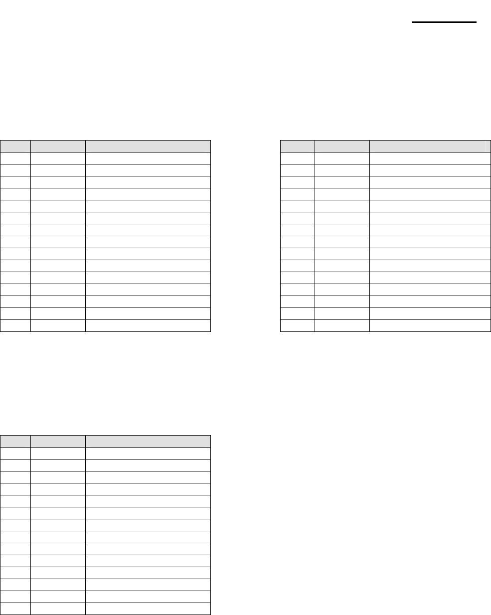
Rev. 3.02 - 73 -
SRP-270
8-6-4 Assignment Connector Pin
8-6-4-1 Connector 30pin
* Connector: Head, head carriage/paper feed step motor, solenoid P/E sensor, control
* Model: 1.0mm FFC cable
Mechanism side: 403-030-099-061
[Taiwan TACK co.]
P/N In or Out Description P/N In or Out Description
1 Output head #6 16 Output ground
2 Output head #8 17 Output ground
3 Output head #4 18 Input head carriage control sig
4 Output head #9 19 Output CA
5 Output head #2 20 Output CB
6 Input head com 24V 21 Input Vcc(5V)
7 Input head com 24V 22 Input Vcc(5V)
8 Input head com 24V 23 Input paper feed control sig
9 Output head #3 24 Output PA
10 Output head #5 25 Output PB
11 Output head #1 26 Output home send output
12 Output head #7 27 Output paper end output
13 Output thermistor 28 Input 24V
14 Output ground 29 Input sol +(24V)
15 Output ground 30 Output sol -
8-6-4-2 Connector 14pin
* Connector: Head control
* Model: Mechanism side : GF120-14S-Ls
[LG cable co.]
P/N In or Out Description
1 Output thermistor (-)
2 Input thermistor (+)
3 Output head #7
4 Output head #1
5 Output head #5
6 Output head #3
7 Input com(24V)
8 Input com(24V)
9 Input com(24V)
10 Output head #2
11 Output head #9
12 Output head #4
13 Output head #8
14 Output head #6

Rev. 3.02 - 74 -
SRP-270
8-7 Disassembly
To disassemble this printer, perform the assembly procedures described in section 8-8 Assembly in the
reverse sequence. First, the main assembly blocks are disassembled and divided into the sub-assembly
blocks, then each of the individual blocks is disassembled.
Disassembling printer components beyond the example shown in exploded view of SMP-710/710N at the
PPL may result in damage to the printer and its functions, so you are advised not to do so.
8-8 Assembly
The assembly process is divided into the sub-assembly and main assembly procedures. First, assemble the
sub- assembly, then proceed to assembling the main assemblies.
Perform assembly while referring to component shapes and mounting positions shown in exploded view.
The '*' symbol in the "Assembly Step" column indicates the need for a (Check) or (Adjustment). The
(Adjustment) process is explained in section 8-9. Even if only a small amount of disassembly has been
performed, confirm the presence/absence of the pertinent adjustment point during assembly.
Circled numbers in the "Assembly Step" column indicate that lubrication is required during assembly of the
component and that such lubrication will be difficult unless performed during assembly.
Details on the application of lubricants or adhesives, including point that require application after total
assembly of the printer, are described in section 8-4 Lubrication and Adhesive Application perform such
application while referring to exploded view.
All small parts are represented by abbreviations as listed in the table below.
* List of abbreviations for small parts
Abbreviation Explanation
WBH Washer faced Binding Head Screw
PH Pan Head machine screw
WPH Washer faced Pin Head Screw
T/T PH Pan Head Taptite screw
T/P PH Pan Head Tapping Screw
PW Plain washer
WW Wave Washer
PSW Poly slide washer with slit
SP Spring pin
RE Retaining ring type-E
PP Parallel pin
FS Franged Screw
Rev. 3.02 - 75 -
SRP-270
8-8-1 Sub-assemblies
8-8-1-1 Carriage Head Assy
Name of Parts Method and Procedure Drawings
BE①RIN G FE (2ea)
CARRIAGE HEAD②
1. At first, set the BERIN G FE①
to be inserted into the shaft of JIG.
* Notice: The direction of insert
is to locate frange downward.
2. And then, set a CARRIAGE HEAD②
to be inserted into the shaft of JIG.
3. Next , set other BERIN G FE① to be
inserted into the shaft of JIG.
* Notice: The direction of insert is to
locate frange upward.
4. Lastly, insert two BERIN G FE① in
the CARRIAGE HEAD② by pushing
the handler of Lever Press.
< Check Point>
Check improper insertion of BERIN①
G FE and fraction of CARRIAGE ②
HEAD.
8-8-1-2 Lever Ribbon Feed Assy
Name of Parts Method and Procedure Drawings
SHAFT REDUCTION ①
“B”
LEVER RIBON FEED②
GEAR REDUCTION ③
“B”
WAVE WASHER④
E⑤-RING (ø2.5)
1. At first, Grease SHAFT on the ①②
LEVER RIBBON FEED with HG-
31S.
2. And then, Assemble ④WAVE
WASHER and Grease WAVE ④
WASHER.
3. Last, assemble GEAR ③
REDUCTION “B” and E⑤-RING
(ø2.5).
8-8-1-3 Ribbon Feeder Assy
Name of Parts Method and Procedure Drawings
SPRING RIBBON ①
FEEDER
RIBBON FEEDER②
GEAR R③IBBON
FEEDER
1. Grease SPRING RIBBON ①
FEEDER with HG-31S and insert
that into RIBBON FEEDER.②
2. And then, insert GEAR RIBBON ③
FEEDER to fit the section of hook.
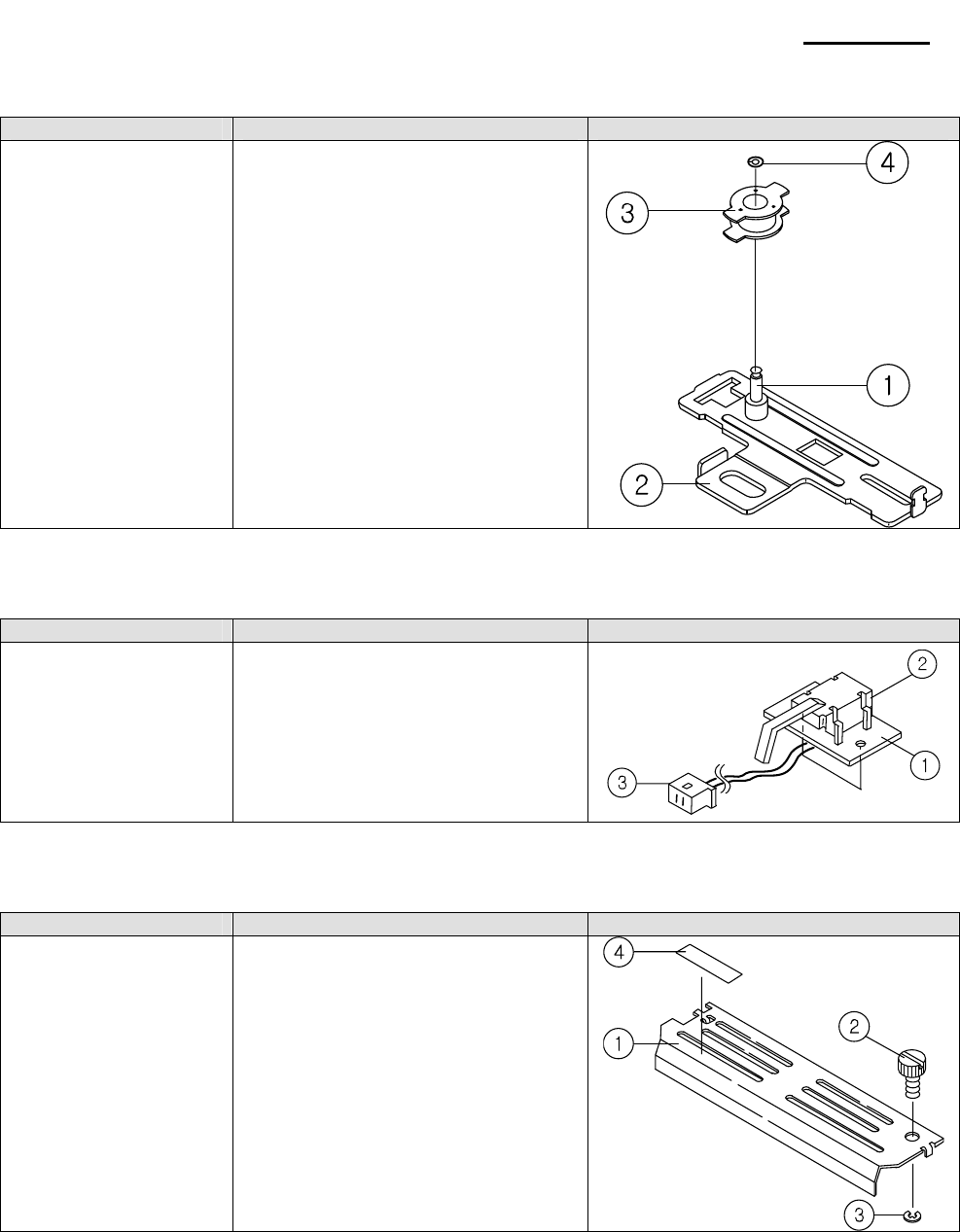
Rev. 3.02 - 76 -
SRP-270
8-8-1-4 Lever Tension Belt C Assy
Name of Parts Method and Procedure Drawings
SHAFT PUL①LEY
LEVER TENSION ②
BELT
PULLEY③
WASHER ④
(2.6*5.0*0.5)
1. At first, grease SHAFT PULLEY①
with HG-31S.
2. Next insert PULLEY and then ③
assemble WASHER (2.6*5.0*0.5).④
<Check Point>
Check PULLEY to rotate smoothly.③
8-8-1-5 Sub PCB Assy
Name of Parts Method and Procedure Drawings
SUB PCB①
SWITCH LEVER②
WIRE ASSY③
1. Insert SWITCH LEVER to fit the ②
hole of SUB PCB.①
2. And then, solder the land on the
SUB PCB bottom side and attach ①
the WIRE ASSY on the land A, G.③
<Check Point>
After soldering, check the frozen lead
and short.
8-8-1-6 Cover Head Assy
Name of Parts Method and Procedure Drawings
COVER HEAD①
SCREW MANUAL②
E③-RING (ø2.5)
CAUTION LABEL④
1. Insert the SCREW MANUAL into ②
the right side hole of COVER ①
HEAD.
2. And then, assemble E③-RING onto
the starting point of a spiral during
adhering closely to the COVER ①
HEAD.
3. Paste the CAUTION LABEL on ④
the right bottom side.

Rev. 3.02 - 77 -
SRP-270
8-8-1-7 Bracket PF “R” Assy
Name of Parts Method and Procedure Drawings
①BRACKET P/F “R”
②GEAR PF IDLE
③GEAR KNOB
④GEAR KNOB IDLE
⑤WASHER (1.6*3*0.3)
1. At first, grease the small shaft of
BRACKET P/F “R” with EM①-501.
Next, insert GEAR PF IDLE, ②
GEAR KNOB, and GEAR ③④
KNOB IDLE. Lastly, assemble
WASHER.⑤
2. Grease the outer diameter of gear
with EM-501.
<Check Point>
Check GEAR KNOB to rotate ③
smoothly.
8-8-1-8 Platen Assy
Name of Parts Method and Procedure Drawings
①PLATEN PLATE
②TAPE D/F
③PLATEN
1. Paste the TAPE D/F onto the ②
PLATEN PLATE and set the sub ①
Assy into the rectangular hole of the
exclusive JIG.
2. Set the PLATEN to fit the groove ③
of JIG and paste by pushing.
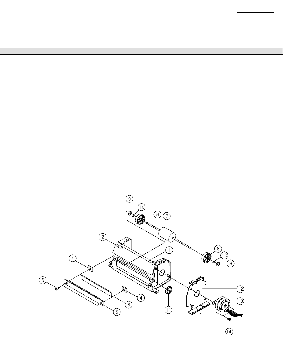
Rev. 3.02 - 78 -
SRP-270
8-8-2 Main-assemblies
8-8-2-1 Base Paper Feed Assy - #1
Name of Parts Method and Procedure
①BASE PAPER FEED
②SHAFT TAKE UP
③TAPE CUSION
④RUBBER PLATE (2EA)
⑤PLATEN ASSY
⑥SCREW SPECIAL (M2.6*7.5, 2EA)
⑦SHAFT RUBBER ROLLER
⑧ROLLER PAPER GUIDE (2EA)
⑨BEARING (2EA)
⑩E-RING (ø3, 2EA)
⑪GEAR ROLLER
⑫BRACKET PF R ASSY
⑬STEP MOTOR PF
⑭SCREW TAPPING (M3*6, 2EA)
1. At first, set BASE PAPER FEED in the JIG. Next, insert ①
SHAFT TAKE UP into the hole. ②Lastly, press it by Lever
Press.
2. Set TAPE CUSION to fit rectangular hole of BASE ③①
PAPER FEED and then, insert RUBBER PLATE in both ④
side.
3. Insert PLATEN ASSY into the rectangular hole and then, ⑤
tighten two SCREW SPECIAL.⑥
4. Make BASE PAPER FEED st①and(right side), and then,
insert two ROLLER PAPER GUIDE and BEARING to fit ⑧⑨
SHAFT RUBBER ROLLER in both side one by one. Next, ⑦
fix the Sub Assy into the back face of BASE PAPER FEED ①
and fit two E⑩-RING into the groove each other.
5. Set GEAR ROLLER on⑪to right side shaft of BASE ①
PAPER FEED and then set BRACKET PF R ASSY.⑫
6. Insert STEP MOTOR PF into the rectangular hole of ⑬
BRACKET PF and drag backward. Next, tighten two
SCREW TAPPING on BRACKET PF R ASSY.⑭⑫
<Check Point>
Check ROLLER to rotate smoothly.
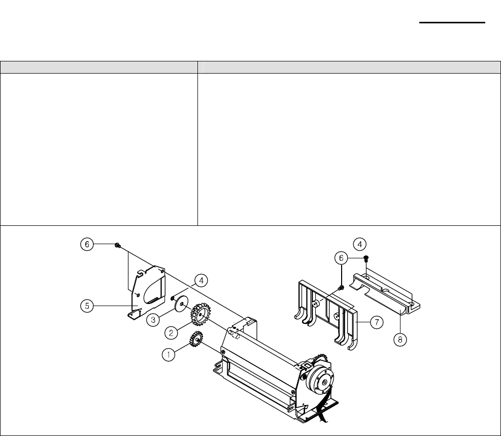
Rev. 3.02 - 79 -
SRP-270
8-8-2-2 Base Paper Feed Assy - #2
Name of Parts Method and Procedure
①GEAR TAPE UP
②GEAR TU PULLEY
③WASHER BELT GUIDE
④WASHER (2.6*5*0.5)
⑤BRACKET PF L
⑥SCREW TAPPING (M3*6, 6EA)
⑦GUIDE PAPER A
⑧GUIDE PAPER B
1. Make BASE PAPER FEED stand (left side), and then, insert
GEAR TAPE UP to fit SHFAT(D①-CUT) (long side is
downward). Next, grease SHFAT and teeth of GEAR with HG-
31S.
2. Set GEAR TU ②PULLEY onto SHAFT and insert WASHER ③
BELT GUIDE. Next fix with WASHER.④
3. Set BRACKET PF L onto BASE PAPE⑤R FEED boss, and
then, tighten two SCREW TAPPING.⑥
4. Rotate BASE PAPER FEED and set GUIDE PAPER A to ⑦
the back face, and then, tighten two SCREW TAPPING step ⑥
by step.
5. Make BASE PAPER FEED stand and set GUIDE PAPER B ⑧
to it, and then, tighten two SCRE⑥W TAPPING step by step.
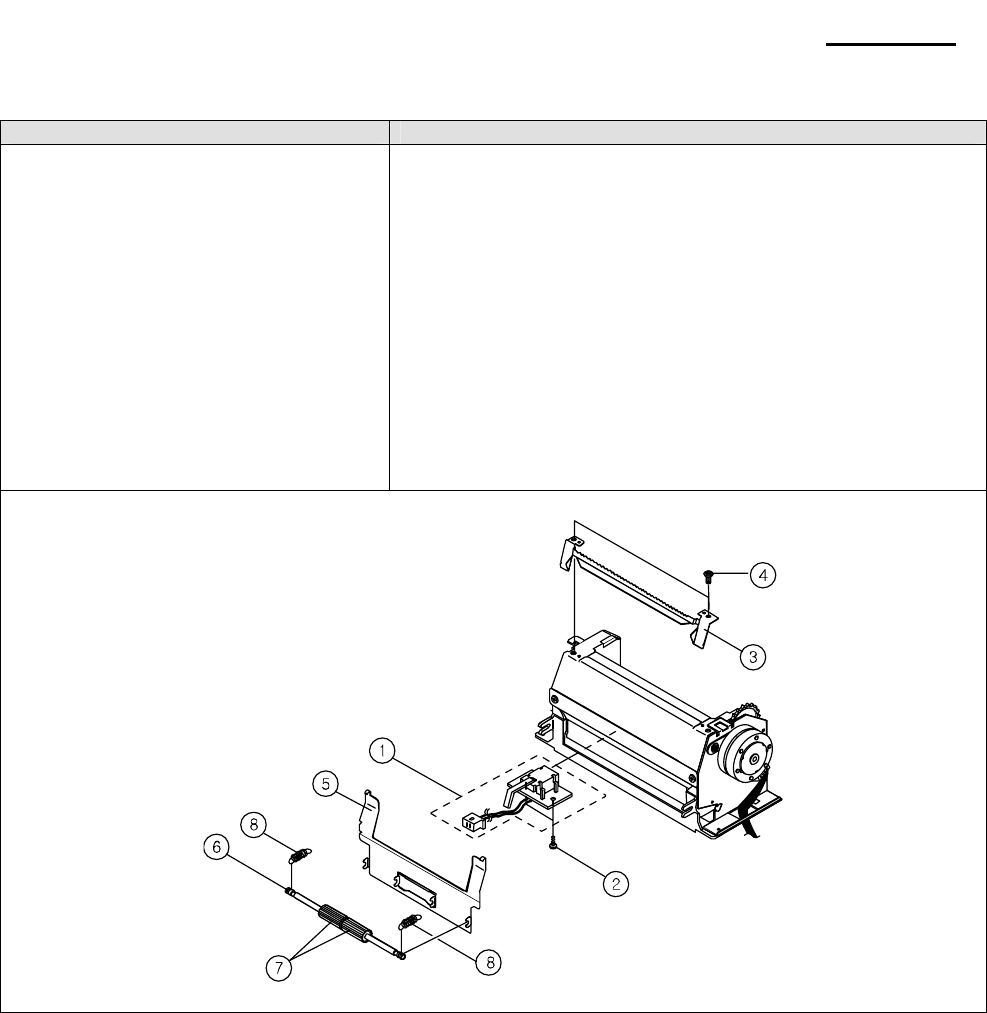
Rev. 3.02 - 80 -
SRP-270
8-8-2-3 Base Paper Feed Assy - #3
Name of Parts Method and Procedure
①SUB PCB ASSY
②SCREW TAPPING (M2*3, 2EA)
③MANUAL CUTTER
④SCREW (M3*6, 2EA)
⑤PLATEN PAPER GUIDE
⑥SHAFT HOLE ROLLER
⑦HOLE ROLLER (2EA)
⑧SPRING HOLD ROLLER (2EA)
1. Set SUB PCB ASSY to fit the hole in the bottom face of ①
BASE PAPER FEED and tighten two SCREW TAPPING.②
2. Set the MANUAL CUTTER to the boss on the BASE ③
PAPER FEED and tighten two SCREW.④
3. Hook PLATEN PAPER GUIDE on the manual cutter in the ⑤
front face of BASE PAPER FEED.
4. Grease section of SHAFT HOLE ROLLER mounted HOLE ⑥
ROLLER and insert two HOLE ROLLER⑦. Next, set SHAFT
to the each groove of BASE PAPER FEED as fitting HOLD
ROLLER into PPG.
5. Hook two SPRING HOLD ROLLER⑧ on the both side of
BASE PAPER FEED.
<Check Point>
Check the location of PLATEN PAPER GUIDE, status of
hooking, coming off.

Rev. 3.02 - 81 -
SRP-270
8-8-2-4 Main assembling - #1
Name of Parts Method and Procedure
①FRAME MAIN C/K ASSY-4
②SERIAL NO. TAG
③TAPE INSULATION
④LEVER COLOR CHANGE
⑤SOLENOID ASSY
⑥SPRING SOLENOID
⑦SCREW MACHINE (M2*3)
⑧GEAR PULLEY ASSY
WASHER (ø2.6*5*0.5)⑨
LEVER TENTION BELT ASSY⑩
SCREW (M3*4)⑪
1. Set FRAME MAIN C/K ASSY①-4 on the JIG.
2. Paste SERIAL NO. TAG in the right side and TAPE ②③
INSULATION on the bending line in the bottom face.
3. Grease SHAFT(6 point) with HG-31S.
4. Insert LEVER COLOR CHANGE④ into SHAFT in the left
bottom side and fit WASHER(2.6*8*0.5).
5. Turn SOLENOID ASSY ⑤and SPRING SOLENOID⑥
downward and insert it into the hole of LEVER C/C and M/F
side step by step. Next, tighten ⑦SCREW MACHINE.
6. Insert GEAR ⑧PULLEY ASSY and then, fit WASHER⑨.
7. Insert LEVER TENTION BELT ASSY ⑩to the hole and then,
tighten SCREW⑪ two-third.
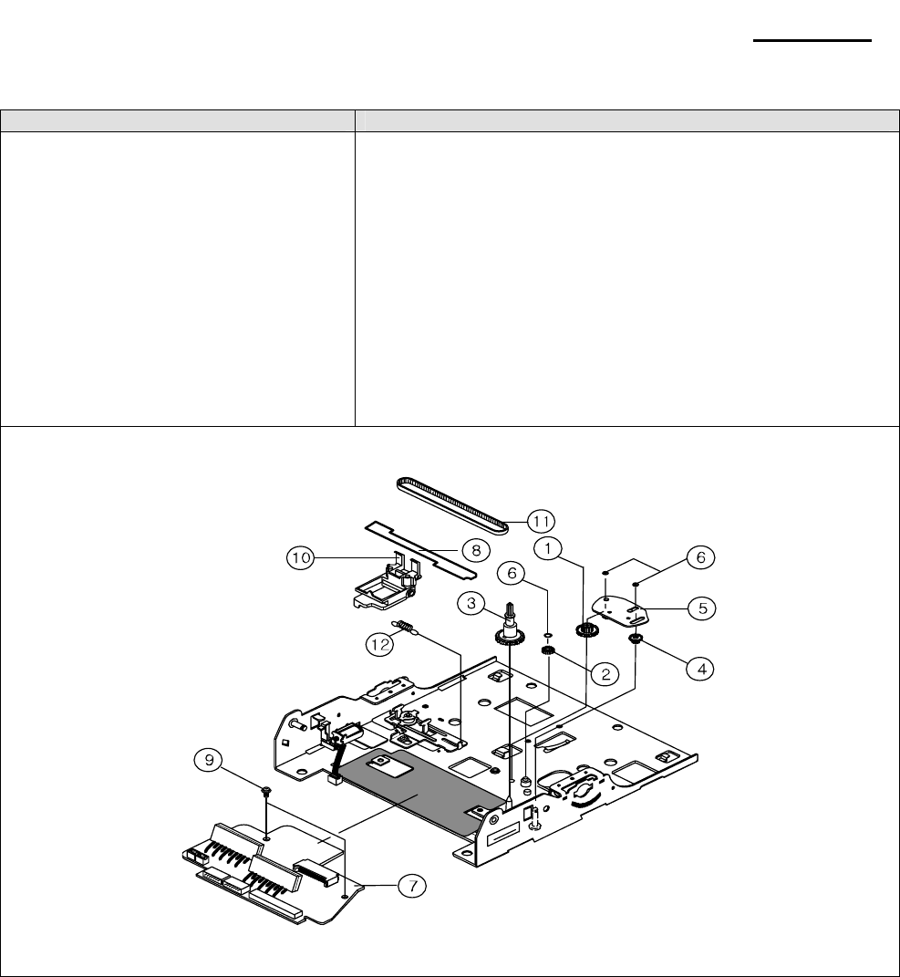
Rev. 3.02 - 82 -
SRP-270
8-8-2-5 Main assembling - #2
Name of Parts Method and Procedure
①GEAR REDUCTION A
②GEAR REDUCTION B
③RIBBON FEEDER ASSY
④GEAR REDUCTION “C”
⑤LEVER RIBBON FEED ASSY
⑥WASHER (ø 2.6*5*0.5, 2EA)
⑦MAIN PCB ASSY
⑧FPC CONNECTOR
⑨SCREW MACHINE (M3*4)
⑩CARRIAGE HEAD ASSY
⑪BELT SYNCHRONUOS
⑫SPRING LEVER TENSION BELT
1. Set FRAME MAIN on the JIG.
2. Set ①GEAR REDUCTION A, GEAR REDUCTION B②,
RIBBON FEEDER ASSY ③and GEAR REDUCTION "C"④
onto SHAFT sequentially. Grease teeth and upper face of
RIBBON FEED ASSY.
3. Insert LEVER RIBBON FEED ASSY ⑤and WASHER⑥.
4. Attach FPC CONNECTOR to⑧ MAIN PCB A⑦SSY. Next,
plug SOLENOID WIRE (block) in connecter 2p. And then, set
it to M/F and tighten two SCREW MACHINE⑨.
5. Insert BELT SYNCHRONUOS into ⑪CARRIAGE HEAD ⑩
ASSY, and then, belt up round PULLEY and GEAR PULLEY.
6. Hoot SPRING LEVER TENSION BELT⑫.
<Check Point>
Check the tear of FPC.
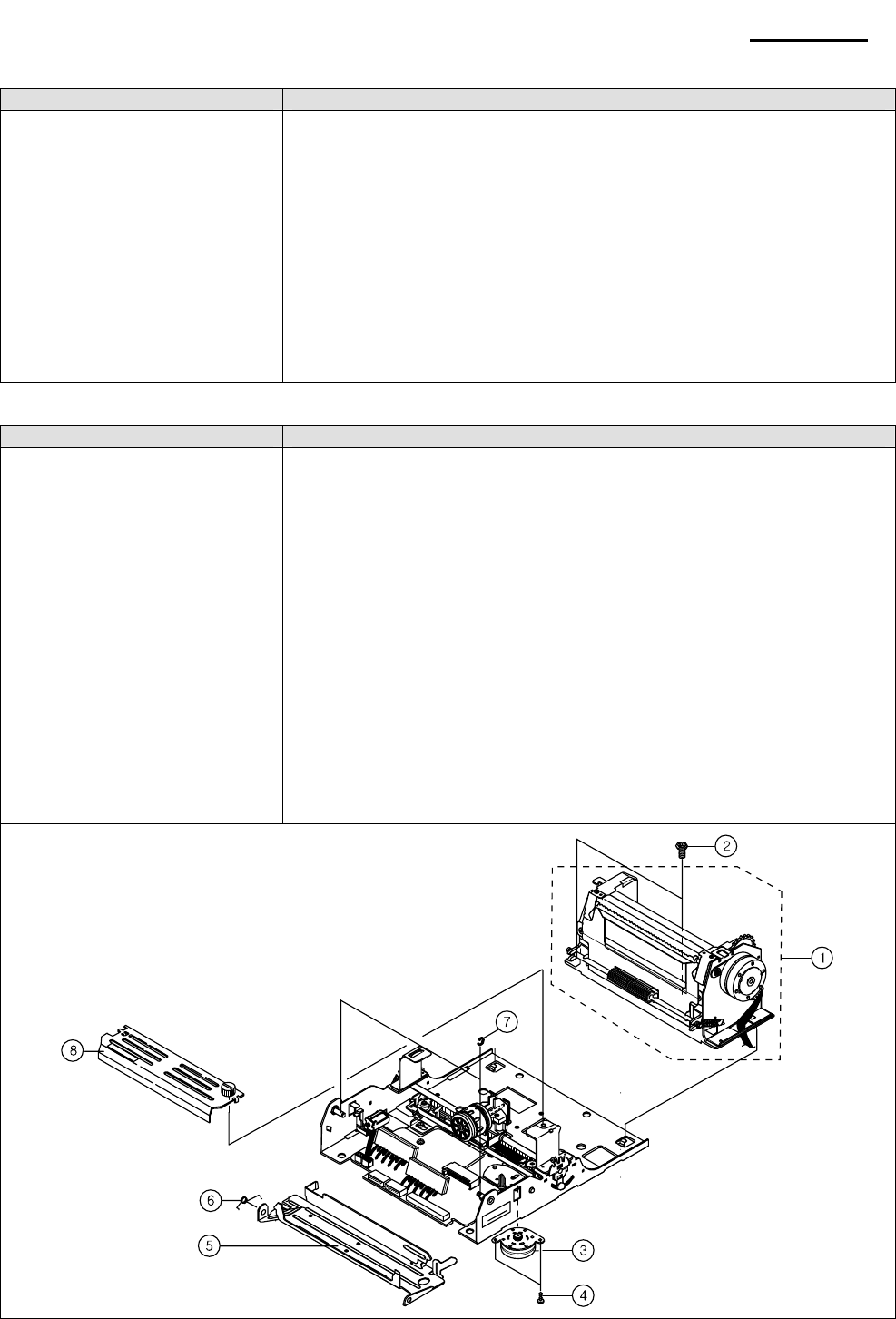
Rev. 3.02 - 83 -
SRP-270
8-8-2-6 Main assembling - #3
Name of Parts Method and Procedure
①AD LEVER
②SHAFT HEAD GUIDE
③SHAFT HEAD CARRIAGE
④E-RING (ø 3)
⑤HEAD PRINT
⑥SCREW (M3*10, 2EA)
⑦BRACKET HEAD COVER “L”
⑧BRACKET HEAD COVER “R”
⑨SCREW MACHINE
(M2.6*3, 2EA)
1. Set FRAME MAIN on the JIG.
2. Insert AD LEVER ①in the left side and then, turn to the downward.
Next insert the other AD LEVER into ①SHAFT HEAD GUIDE ②and
insert the Sub Assy into F/M from right to left and then, turn AD LEVER
downward.
3. Insert SHAFT HEAD CARRIAGE ③from left to right and fit E④-RING
in the left side.
4. Insert FPC into HEAD PRINT ⑤and set HEAD Assy to CARRIAGE
HEAD, and then tighten two SCREW⑥.
5. Tighten the screw mounted to LEVER TENTION BELT ASSY
completely.
6. Fit ⑦BRACKET HEAD COVER "L" and BRACKET HEAD COVER ⑧
"R" to both boss and then tighten two SCREW MACHINE⑨.
8-8-2-7 Main assembling - #4
Name of Parts Method and Procedure
①BASE PAPER FEED ASSY
②SCREW MACHINE
(M3*6, 3EA)
③STEP MOTOR H/F
④SCREW (M3*4, 2EA)
⑤RIBBON FRAME
⑥SPRING RIBBON FRAME
⑦E-RING (ø3, 3EA)
⑧HEAD COVER ASSY
1. Set FRAME MAIN on the JIG.
2. Put BASE PAPER FEED ASSY① wire into the rectangular hole and
drag it. Next, set BASE PAPER FEED ASSY and tighten three ①
SCREW MACHINE②.
3. Turn up FRAME MAIN and then set STEP MOTOR H/F③ to the hole.
Next, tighten two SCREW④.
4. Insert SUB PCB, STEP MOTOR P/F, STEP MOTOR H/F WIRE to the
connecters of MAIN PCB ASSY sequentially, and then alignment and
fix the WIRE ASSY by pressing the hooks.
5. Grease on the CARRIAGE HEAD, SHAFT RIBBON FRAME and
SHAFT HEAD CARRIAGE with HG-31S.
6. Hook SPRING RIBBON FRAME ⑥on the RIBBON FRAME and ⑤
insert the other side on the left side of SHAFT. Next, insert RIBBON
FRAME onto right side of SHAFT and insert the other side of RIBBON
FRAME onto SHAFT. Lastly, hook the spring (For more detail refer
next page.)
7. Tighten three E⑦-RING. And assemble HEAD COVER ASSY⑧.
<Check Point> Check the setting position of RIBBON FRAME and jam.
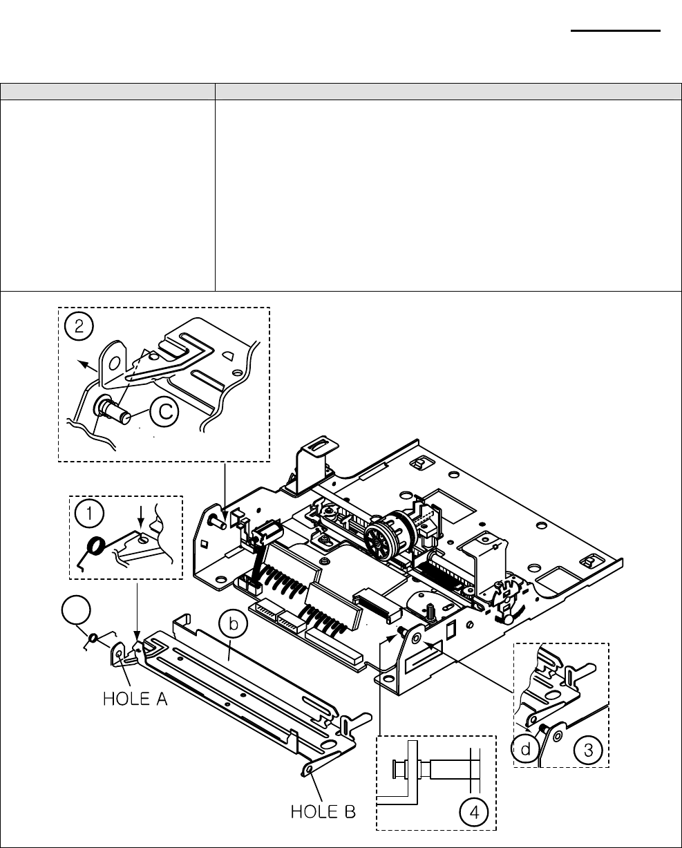
Rev. 3.02 - 84 -
SRP-270
8-8-2-8 Main assembling - #5
Name of Parts Method and Procedure
①RIBBON FRAME
②SPRING RIBBON FRAME
③E-RING (ø3, 3EA)
1. Insert ⓐSPRING RIBBON FRAME into the hole in left side of
ⓑRIBBON FRAME to ward arrow on shows in Fig. 1 detail.
2. Set SPRING RIBBON FRAME ⓐonto the SHAFTⓒ and then, move
the RIBBON FRAME toward arrow.
3. Next, insert RIBBON FRAME onto SHAFTⓓ toward arrow an shows in
Fig. 3.
4. And then, insert the other hole A of RIBBON FRAME onto SHAFT ⓒ
and then, adjust the position of RIBBON FRAME to the center as
shows in Fig. 4.
5. Firs t E-RING to SHAFT ⓒand two E-RING to SHAFTⓓ.
6. Check RIBBON FRAME to move smoothly as operating it up and
down.
a
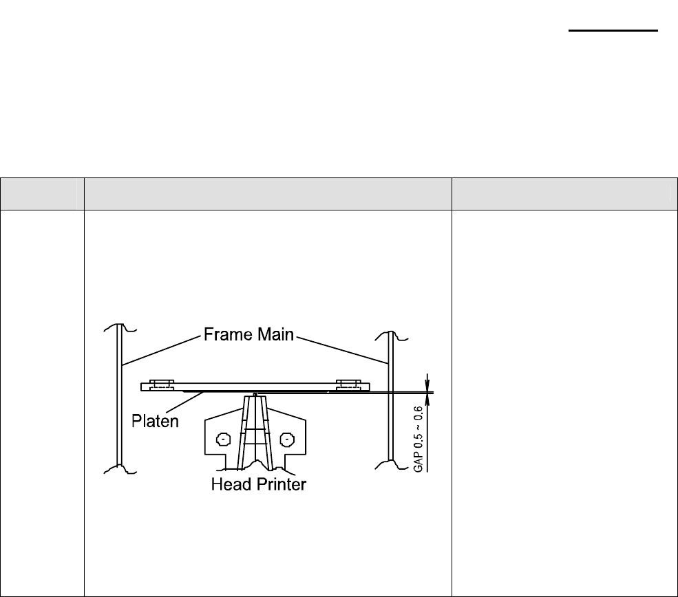
Rev. 3.02 - 85 -
SRP-270
8-8-3 Adjustment
When assembling this printer, be sure to refer to the required adjustment procedure.
To ensure normal operation of the printer after disassembly or replacement of a Component for maintenance
or repair. Be sure to perform along to the required method.
* Adjustment of Head gap
Adjustment
Step Description Points in Adjustment
1
2
3
4
• Rotate Gear lst Reduction to move the Head unit
to L side.
• Insert the thickness gauge between Head unit and
Platen, then rotate the Ad.
Level L and adjust the gap.
• Move the Head unit then check if the proper
gap from R side center has been achieved.
• If Head gap is not proper, adjust Head gap by
rotating Ad.Lever R.
- Appropriate gap: 0.50~0.60mm
- In order to make the gap narrow
(wide), turn Ad.
Lever to mark ’-(+)’
- If gap is not correct, repeat once
more.
(Replacement of Head unit)
Follow below steps for replacing Head unit
1. Loosen the Ribbon frame
2. Disassemble the Head unit from the Head Carriage and take out the Head FPC from the connector of
PCB Assy.
4. Replace the Head unit and assemble, according to the order of sub Aassy-1
5. After assembling, adjust the gap as above “Adjustment” indicates.
6. Assemble the Ribbon Frame.
