2720 Manual
2014-04-30
: Bk 2720 Manual 2720_manual en-us manuals s
Open the PDF directly: View PDF ![]() .
.
Page Count: 13
H(Pf;IEA'#.
lnstruction
Manual
Model
2710
Pen-type
Digital
Multimeter ((
Limited Three Year
Warrantv
B*KPrecrsionwarrantstolSeoilqrnalpurchaserlhat tsproductandthecomponentpartstherecf
,w bejreefromdefecis
n
workmansh
p
anc xrater als for
a
penod
of three
years
from
the
date of
ourcnase
3*(PrecrsonwrtJ.wthoutcharge
-eparorreprace
at t'soptron.defectrveproductorcomDonentlans
Returneccrod!ai
m,,cr 6a:.^^mnrniF^ nr, nrnnf nf 'no d.fo r rno f^rm : a2laq ro-ornr
s rq'vu e vv'P r
T-
cntarr
Na"ari\ :o re'aEe
^:-e
u S A. r1ts
proouct
mJst be
reg
stereo
bv
corpletr"g and
ra lrrg:l.e
e"c oseo
rara-:.
:ardtcB-KPrecrson
103'1
SegovraCrrcle
Placentra,CA92BT0withinfifteen('1
5rdaysfromproof cf
purcnase
Exclusions
: This
warranty does not
apply
in
the
event of misuse or abuse of the
product
or as result of
unautho-
rized alternations or repairs. lt is vold if
the serial
number is altered, defaced or removed.
3+KPrecrsronsrraii notbe labefor;nvconsequentraldamages.includingwithout rmrtatron\larnagesresLtrngfrom
css
of use
Sornestatesdonotaliowlmrtatronofincrdentalorccnsequentraidamages solheabovelimitatronorexclusronmay-or
appry
ro
_vou.
-qrs
JVariartv
l'!es
.
ou soecrfic
''gnls
a1d
you
:ray
lave
othe.'gnts
ruricn
vary'rom slate-io-state
Date
Purchased
INTRODUCTION
1-1
Unpacking
and Inspection
Upon removing your
new
Digital
Multimeter
from
its
packing
,
you
should
have
the followrng
items
1 Digital
Multimeter.
2. Test lead
(one
black).
3 Test
probe
set
4.
Operations
manual.
5 Test
CIip
(black)
6 Carrying
case
1-2
Meter
Safety
Terms
as Marked
on
Equipment
I nfrerufloN - Refer
to
manual
tr DoUBLE
TNSULATION
-- prorection
Ctass
I
?' DANGER
- Risk :f eieclrtc
shcck
irirCClS n -lls:rlai-a
,4 :i'is s,q'cc rctcates
ltiz"= catia.ai'/ at:ther nicrrat cr s 'o,r'a
---_- Aattery.
.1
-3
Front Panel
reier lc i'qure ' ard ta
ite'c,lcwinE
iuncered 3iepS
ic
fantiiarize
rcurself
'
::rt':,s )'c :a.'aa'c(,
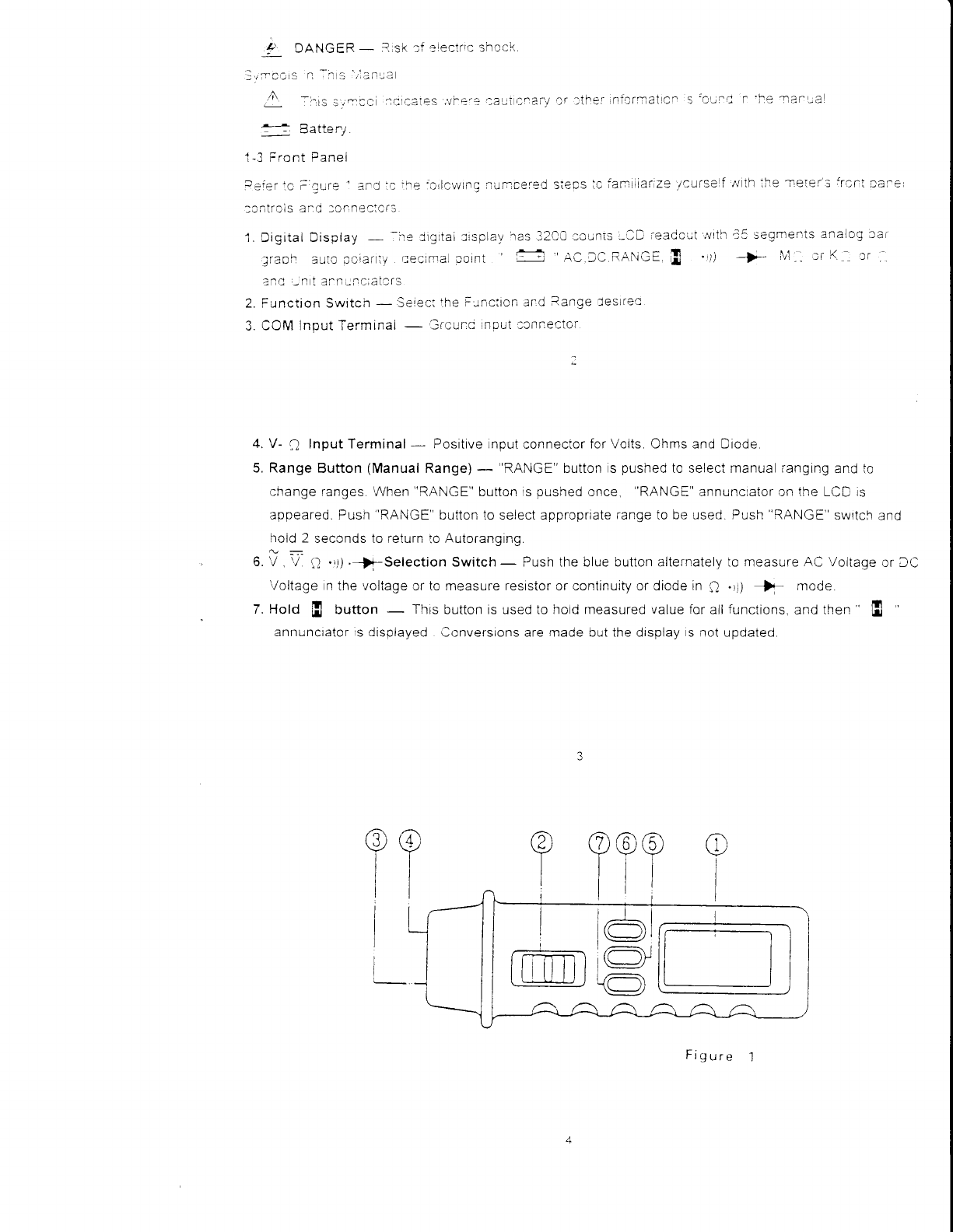
1. Digital Display
- -:e:igrtai
:rsplav
ras
32C0.cLinis,lD
readc;t,vrth
;raof. aiio ocrani'v
recimal coint ! t- AC
DC
RANGE E '))
?ad -n t ai-n;ncratcrs
2. Function Switch
- Serecl
lhe
i.lnc:icn ar:d
Range ieslrec
3.
COM lnput Termin3l
- !66;i1c npul .cnnector
a -)'e
rar!aL
lrth ihe -nete
j-'3
frcni
Dare
i5 segments
analog
:rai
1,1 :, I :'
4. V-
n Input Terminal
- Positive rnput
connector
for Volts. Ohms and Diode
5. Range
Button
(Manual
Range)
- RANGE button s
pushed
to select manual
i-angrng
and to
change ranges
\/Vhen
"RANGE"
button rs
pushed
once, 'RANGE"
annunciator on the LCD rs
apoeared. Push
"RANGE"
button io select appropriate
range
to
be used. Push
"RANGE"
swrtch
and
hold 2 seconds to
return
to
Autoranging.
Q-
6. V ,
\/ Q .rt)
'-)i-Selection Switch
- Push the blue button alternately to measure
AC Voltage
or f C
'/oltage
n
the
voltage
lr to measure
resrstor
or continuity or diode
in
Q .
rl F mode
7. Hold fi button - This
button is used to hoid measured
value for
all
functions.
and
then
' fi
annuncrator
s
disorayed ,lonversions
are maoe out the drsplay s
not
upoated.
?? ??
?
I
[r--=n
I-ILqJJ
Figure
SPECIFICATIONS
2-'1 General
Specifications
Thrs nstrument
has
been
desrgned
n acccrdance rvrth
r-lL
1241
and
tEl oLtbitcation li;10
Pt l .
as. .l
Safety Requtrements for
Erectrrcal
ier:rpment
for measrrement 'loutrcl
and labratory
,tse Ttts e,,,el
tt
satety .an nly
be
JUaranted
,vi-rtie
ihe
irmlts
of 22 are
--bserved
Display
:
The
Lrqurd crystal
Display
tLCD)
wrth a nrarrmunr readrng
cf 3200 ancj 65:egmenrs Dar
gra pn
Polarity lndication
:
Aulomiatrc poslttve
rmplred negative inotcateo
Overrange
lndication
: 'OL'cr ',OL'
Low Battery
Indication : f-i 'is displayed,,vhen the baitery voltage
droos Deicw operattng
\/oitage
Sampling :
2 times t
sec
for
digrt l2lmes/ sec
ior
anaiog
bargraph
Auto Power
Off : Approx 10 minutes
2-2 Environmental
Conditions :
lndoor
use.
Maximum
Altitude
: 2000
meter
Installation
Category
: IEC
'1
010 600V
Cat II 300V,
Pollution
Degree
:
2
Operating
Ambient
: 0
i, to 50
r ,
0 to 80%
R n
Storage
Temperature
:
'20
r to
60
il 0 to
B0%
R H
Temperature
Coefficient
: 0
15 x
(SpecAcc'y)/
1, <
Power
Requirements
: IEC 1.R03
AM4 or
AAA stze
1
Battery
Life
: Alkaline
800 hours
Cat ilt
when
battery
removed
from
rneter
1B r-
or
,28r,
.5Yx2
Dimensions
(W
x H x D) :42mm x 145mm
x24mm
Accessories
: Battery
(rrrstalled) and operators
malrual
2-3
Electrical
Specifications
Accuracy
is i (%reading
+
numberof
digits)
at23i' 51 ,
ress
than
80
% R H
(1)
DC
Votts
Accuracy
(0
7% + 26911 600V
DC
or
600V
rms
Range Res
olLrtio
rr Accuracy Ove
l)
r(
:JV
30v
:10(rV
ti00v
I
rrrV
It.lfftv
ltlotltr
1V
(17?,,rJg
t 5dgtt
(1
7',;,rdg
' 5dgltr
4(lFlz t0 i;(l(Ji
lz
lri l(i
liUil
(2)
AC
Volts
^
Frequency
Response
.
4Otlz 30Ullz
fr,rr .1V
ilangc
lllput
ltnpedance
: i[)lr4
1r
l Iuss
tilal ]001,f:
Tiic
teatltrtg vvtll trc
a irltle
rollrrrg
alrlrroxrralely
2 5 r;oLrrrts
over 2il0V
(3)
Resistance
Voltage:13Vapprox
-For04V-
08V
Overload
Protection
:
600V
DC/AC
rms
max
continuity
: BLiilt-in
buzzer
sound
when
resislance
rs ress
approximaterv
than
20r)
(5)
Auto Power
Off
The
nreter
will
aulomalically
shut
itself
off
after
approximately
1o
minutes
aiter power
on The
meter
can
be
turned
back
on
by
pushing
'RANGE'
kev
bunon
er voltage
rotecti<_r
rr
Resolution Overloa
cl
Protection
6tl0V
Dtl
or
(i0(lV
rrls
' (3u,,lrdg
+ 5cjgt)
Open
circuit
(4)
Diode
Check
and
Continuity
Range Resolution Accuracy Max.
Test
C
urrent Max.
Open
Circuit
Voltage
+i* 1mV (1.5%rdg
+
5dgt) I 5MA 33V
10
OPERATION
--rs asir!reiil'as Je-al :es qned
ifrd
.-sie! t, acc:,r,latce,vttf
lFC
P'.-]bircattcn
.Cr0 Sateti =.a,:.,
--
.ier:s'ci F:ecir:r
c lvleasL-rtng
ipcarai'.rs.
anC
"as been
suppitec n
a safe:cncttior-
Ilrs,nsir..rcir:-
lan:a :cnialrs
;';me iicTraitan
and uarai.,q
wnjcn ave
'.c
ze'c:ic,,^tec
cv
:ie -)sa.,.a
aasrr--
:a._.
aaata,ttae
anc
io -elatr:te aslr!rieai n.iale -:roilicr
I ,-, Preparation
and Caution
before
Measurement.
I , 3eicre measuT:ne.: /vari-;r ,tD
.cr 3t east !C seconds
2 ',rr'hen
lhe iur-cticn
switch se ector
rs
:ranged ,iLrrirg
,'neasuren'ent
be sure
ac so tnl'r aftei
r-.Tno,.r
r-l
ihe :est
eads
irom
ihe equrpment.
3 lf
lhe equlprnent
ls
.:sed near
rcise
3ener-ating
eeuipment be aware
lhat
Cisplav rna,r
beccme
-.rnstallie
cr ndicate
arEe
:rrors
'r 1\ lvlaxrrnum
ratec'roltage
ic --adh
icr
voitage
rneasurements
terminals
rs
60C\,,AC,DC
CAT -i
3-2 Voltage
Measurements
i Connect
the red
test
probe
to the
'V 1l
'input
terminal
and
ihe other
(black)
test lead
to
the
"COlvj
terminal.
2 Set
the
function
switch to V -V position
3 Push
the
blue kev
to the ACt/
or
DCV function
4 Connect
ihe iest
probe
and
lead
to
the device
to be measured
A WARNING
iO AVOID
=LECTRiCAL
SHOCK HAZARD
OR DAMAGE
TO
\,1FTER.
DO NOT
A
' ATTEMPT
io lv'lEASURE
vOLTAGE
THAT
MIcHT
EXCEED
600 voLT DC
oR 600
VOLT
AC DO
NOT
APPLY
MORE THAN
600 DC
OR AC
RMS
BETWEEN
THE
] COfulMON
]NPUT
TERMINAL
AND
EARTH
GRoUND
12
NOTICE
UNSTABLE
DISPLAY
MAY
OCCUR
ESPECIALLY
AT
3OOmV RANGE.
EVEN THOUGH YoU
DON'T PUT
TESTED
LEADS
INTO
INPUT
TERMINALS
IN THIS
CASE
IF
AN
ERRONEOUS
READING
IS
SUSPECTED
SHORT
THE
'V-!:]
'TERMINAL
AND THE COM'TERI\4INAL
AND
MAKE
SURE THE
ZERO
DISPLAY
3-3 Resistance
Measurement
1 Connect
the red
test
probe
to the
"V-
il "
terminal
and
the other
(black)
test Iead
to the
"COM"
terminal
2 Set
the function switch
to
":) .r))
.
-)i- position
and
push
the
blue
key
to select resistance
function
3. For
correct reading,
ensure
that
the device
being tested
contains no
voltage.
4 Connect
the test leaos
across
the resistor
to be measureo
In
order
to ensure the
best accuracy
.n
measurement
of low resistance
.
short
the test leads
before measurement
and memory
the
test
probe
resistance
in
mind This
necessary
to
subtract for
the
resistance
of the
test leads
themselves
13
3-4 Contrnuity
Check
by Buzzer
I l:nrecl::e:ec:esi 3r:oe';:l'? ',' ':err'-irai
and:he
liier blacK
iesi
ead
:c:l.rz
?)it1 :a,* --_
2.
Set the funcitcn
swiicit'o
'__:.rl
-|-" ccsitjon
ar,d:ush
fhe
olue xey
ic;eiect
tCntinlrl,i,r-r..i
,-
I 'l:nnec: .he :esl
ataae
iac eaa
:a :i-e
t;Ta!
I :o
ae
-reas!r:a -l'.e
aaz72t,vr
I
sclnd ,r
il.e
i?s;sia.
.:j
:f ine : rcirt :'.eaSLi--oa
s c,r'/ef
tl-ar-
2i
3-5
Diode
Check
1 Sei ihe iuncttcr-:
slvrtch
at ' , ..r) -)*- Dcsttlcn,
and
oush
ihe ciue
<ey
io Seieci
JicCe
iuncl;cn
2.
Ccnnect clacr
iesi eac
io 'Cli\rj,'
ierrninai
anC red
crobe
io ,,i_
,:.,rncut
iermrnal
3. Connect
test
orobe and
leac
io
the
diode
normailv
the forward
rroitage
drop cf good
srlicon
orode:s
5nc\'vn ce|'veen 'lCC\r
io 30Ct,' f il'e diooe
..]nder
test rs
oefective.
't0C' ,sncri :rrcuiti
:r 'ljL,
inon-,tcnductancer
is
dispra,vec
Re'''erse
:heck
:f dicCe
if
the
riode
!ncer
iest is
defeclive
"!C0"
or
cther,ralue
afe io
oe displayec.
.A
4.1 MAINTENANCE
REPLACEMENT
7\
wnnrulruc
TO REDUC:
RISK
OF ELECTRIC
SFIOCK
DISCONNECT
TEST
LEADS
BEFORE
OPENING
CASE
1. Test lead
Assembly : Part No. TL
9 Max 1KV
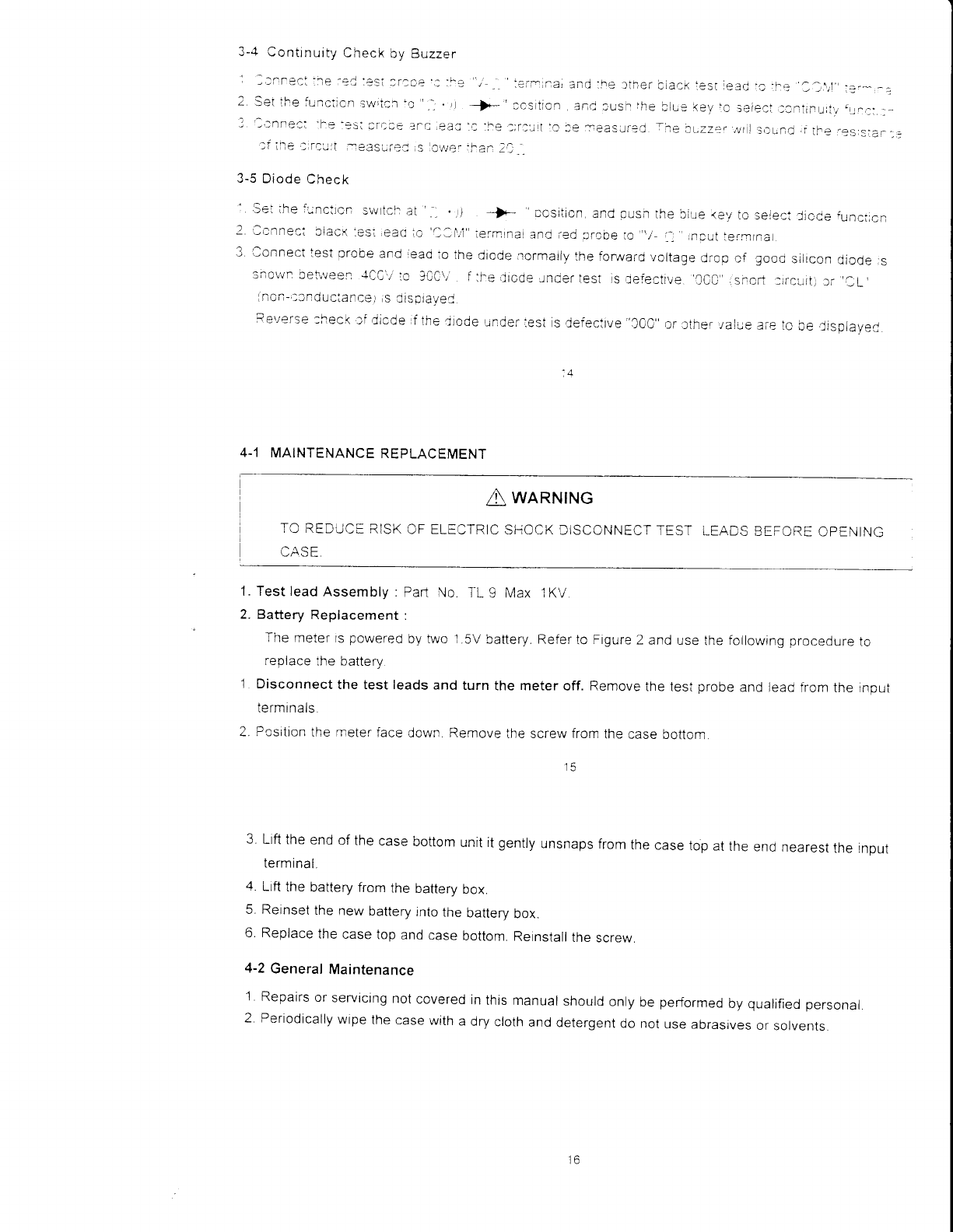
2. Battery Replacement :
The meter ts
powered
by two 1.5V
battery. Refer
to Figure
2 and use
the
foilowrng procedure
to
replace
the battery
1 Disconnect the test leads
and turn the meter off. Remove
the test
nrobe and leacl frnm
the inpul
Iermlnals.
2. Pcsition
the meterface
down Remove
the screwfrom the
case bottom.
3 Ltft
the
end
of
the
case
bottom
unit it
gently
unsnaps
from
the
case
top
at
the
end
nearest
the rnpul
terminal
4 Lrft
the
battery
from
the
battery
box.
5. Reinset
the
new
battery
jnto
the
battery
box.
6. Replace
the
case
top
and
case
bottom.
Reinstall
the
screw.
4-2
General
Maintenance
1 Repairs
or
servicing
not
covered
in
thrs manual
should
only
be
performed
by
qualified
personal
2 Periodically
wipe
the
case
with
a
dry
cloth
and
detergent
do not
use abrasrves
or
solvents
15
?;::.'='
Figrr-r 2
Service
lnformation
Ine
orcduct
rn
the
origrnal
Oackagrng
wrth
proof
of
curcnase
to
tne ilelow
performance
prcblem
anc retuTn
any
leads..onnectors
anc
accesso|es
thai
Warranty
Service
:
please
rerurn
address
Clearly
state
n writtng
ihe
yOLl
are ,S,ng
rvrtn
Ine
devrCe
Non-Warranty
Service
: Please
i'eturn
ihe
proouct
rn the
oflgrnal
packaging
to
the
below
address
ctearly
state
rn
wrrtrnq
the
performance
orcblem and
return
any
eads
.onnectors
and
aicessories
that
you
are
using
wjth
the
'levlce'customersnctonooenacccuntmustincludepayrnent
ntheformof
arnoneyorderorcredrtcard.Fcrthe
most
current
repair
charges
contact
the factory
before
shrpping
the
product.
Return
allmerchandrse
lo
B'KPrecrsion
ivrth pre-pard
shioprng.
The flat-rate
reoaircnarge
rncludes
rerurn
shrpp ng
io
ocations
nNorth
Amerjca
Forovernrghtshrpmentsandnon-NorthAmercashrpprngfeescontact
B+K
P
rects
ro n.
Include
with
the
instrument
your
complete
return
shipping
address.
contact
name,
pnone
number
and
description
of
problem.
H(FBEA'ffiIU
P/N
: 480-797-9-001
Printed
in Taiwan
Instruction
Manual C€
INTRODUCTION
1-1
Unpacking
and
Inspection
Jcon
removing your
new
current
transducer
rr'.fr
it's packing
,you
should
have
the
:.'rlc,,r,ing
items:
'. lurrent
Transducer
.
2. nstruction
manual.
1-2
Meter
Safety
Terms
as Marked
on
Equipment.
MODEL
CH-,IOO
CI.AMP
HEAD
FOR
PEN-STYLE
DMM
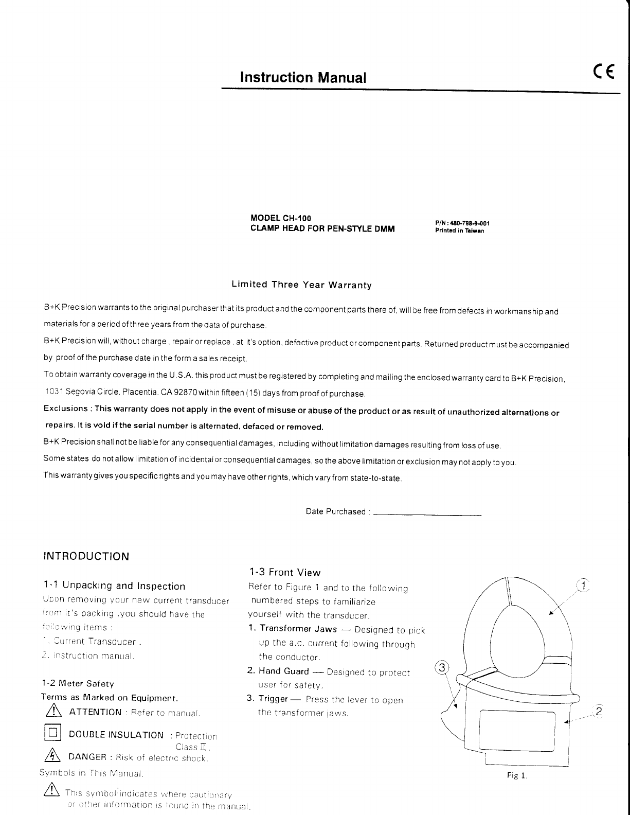
1-3
Front
View
Refer
to Figure
1
and
to
the
following
numbered
steps
to familiarize
yourself
with
the transducer.
1.
Transformer
Jaws - Designed
to pick
up
the
a.c.
current
following
through
the
conductor.
2. Hand
Guard
- Designed
to protect
user
for
safety.
3. Trigger- Press
the lever
to open
tf e
t"ansf
orrer law
s.
P/N
:480.798-9.001
Printrd in Taiwan
Limited Three year Warranty
B+K Precision warrants
to the
original
purchaserthat
its
product
and
the
component
parts
there
of, will
be free
from
defects
in
workmanshro
and
materials for
a
period
of three
years
from
the data
of
purchase.
B+K
Precision
will,
without
charge
.
repair
or
replace
. at it's
option,
defective
product
or component
parts.
Returned
product
must
be accompanred
by proof
of the
purchase
date in
the form
a sales receipt.
To
obtain warranty
coverage in
the
U.S.A. this
product
must
be registered
by completing
and matling
the
enclosed
warranty
card
to B+K
precision,
1
03 1
Segovia circle,
Placentia
cA g28T0
within
fift
een
(
1
5) days from
proof
of
purchase.
Exclusions
: This warranty
does not
apply in
the
event
of misuse
or
abuse
of
the
product
or as result
of unauthorized
alternations
or
repairs.
lt is vold
if
the serial
number is
alternated,
defaced
or removed.
B+KPrecisionshallnotbeliableforanyconsequentialdamages,
includingwithoutlimitationdamagesresultingfromlossof
use.
Somestatesdonotallowlimitationofincidentalorconsequentialdamages,sotheabovelimitationorexciusionmaynotapplytoyou.
This
warranty
gives you
specific
rights
and
you
may
have
other rights,
which
vary from
state-to-state.
Date Purchased
A nrrervroN
: Ref
er ro nranual
lnl oorr,-E
TNSULATToN
:
protection
DANGER
Ltd5: I
electrrc
shock
Symbols
in
This
:Risk
oi
lvlanual. Fig
l.
LJr
tliteT tillormatton
rs
ioLtnd]lt
il-e nt;lnual.
1-4
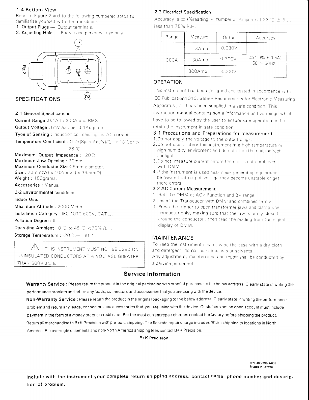
Bottom View
Bef er to
Figure
2 and
to the
f
ollcwing numbered
steps
famrliarize
yourself
with
the transducer.
1. Output Plugs
- Output
terminals.
2. Adjusting
Hole
- For service
personnel
Lrse only.
/-}
?
2-3 Electriacl
Specification
Accuracy is | (%reading
- number
of Ampere)
at 23 C j r
le.s.s
than
759l"
R.H.
Rang
ell easu
re Output Accu
ra
cy
300A
3Amp 0.030v
+
(1.9o/o
+
O 5A)
50
- 50Hz l
3OAmp 0.300v
300Amp 3.000v
OPERATION
This instrument
has
been
designed
and tested
rn
accordance,uvrth
IEC Pubiicationl
Ol O, Saf
ety
ReqLrrrements
for
Electronic
MeasurrnQ
Apparatus,
and has
been
supplied
rn
a safe
conditron. This
rnstruction
rnanual
contarns
sonte inf
ormation and
\r'/arnings,,r/hritll
have
to be
followed
by the user
lo ensure
safe operation
and
tcr
retain
the
instrunrent
in
sate conditron.
3-1 Precautions and Preparations
for measurement
'l
. Do not
apply
the
voltage
to the oUtput
DluCs
2.Do not
use
or store
this
rn:strument
in
a
h.th
temperature
or
hiqh
humidity
envrroment
and
do
not
stor. the
unit
indirect
sunlrgnl.
3.Do not nrea.sure
current
before
the Ltnit
s
nct
conrbirred
With
DMM.
4.lf
the
instrument
is
used
near
noise generatrf
,t.qutoment
be aware
that
output
vcltage
nrav
becorne urrstable
or
ger:
more
errors.
3-2 AC Current
Measurement
1.
Set the DMM at ACV tlnction
and 3\i
ranoe.
2. lnsert
the
Transducer
with DMM and
combined
firrrlv.
3. Press
the trigger
to open
translormer
ja,,rrs
and r;lamp
,ne
conductor
only, makinq
Srtre that
the
la\,v
rs
frrmlv
closerj
around
the conductor,
then
r..ad the
readinq
fronr
the dtqrtal
display
of DMM.
MAINTENANCE
To
keep
the
instrument
clean,
,wipe
the case
with
a
dry c oth
and
detergent,
do not
use
abrasr,;es
or
solvents.
Any adjustment,
maintenance
and
r-.parr
shall be
conducied
bv
a
service
personnel.
T
IO
cu
rre
n
l.
.:
18
Cor
SPECIFICATIONS
2-1 General
Specifications
Current Range :0. i A to 3O0A a.c.
RMS
Output
Voltage
:1 mV
a.c.
per
0.
1
Arnp
a.c.
Type
of Sensing : Induction
coil
sensing f
or
AC
Temperature
Coefficient :
O,2x(Spec
Acc'yii'C
28'C
Maximum
Output lmpedance
:12A?
Maximum
Jaw Opening
:
3Omm
Maximum
Conductor
Size:29mm
d ameter.
Size: 72mm{W)
x 1O2mm(L)
r 36mm(D)
Weight
: 1
50grams.
Accessories:Manual.
2-2 Environmental
conditions
Indoor
Use.
Maximum
Altitude :
2OO0
Meter
Installation
Category:lEC
1010
60CV, CATtr
Pollution
Degree
:-n.
OperatingAmbient:
0 L ro dE C . /boo F.--j
Storage
Temperature
: 20 'C-- 60 Cl
THIS INSTRUMENT
IV]UST []CT
3E
USED
ON
JI.I]NSULATED
CONDUCTORS AT A VOLTAGE
GREATER
ilAN 6OOV
aadc.
Service lnformation
Warranty Service : Please
return the
product
jn
the original
packaging
with
proof
of
purchase
to
the
below
address
Clearly
state
in writing
the
performance problem
and
return
any
leads,
connectors
and accessories
that
you
are using with the
device.
Non-Warranty Service :
Please
return
the
product
in the originalpackaging to the below address.
Clearly
state in
writing
the
performance
problem
and
return
any
leads,
connectors
and accessories
that
you
are using
with
the device.
Customers
not
on
open
account
must include
payment
in
the
form of a
money order
or
credit card. For the most
current
repair
charges contact
the
factory
before
shipping
the
product.
Return all
merchandise to B+K
Precision
with
pre-paid
shipping. The
flat-rate
repair
charge includes
return
shipping
to
locations in North
Ameflca.
For overnight shipments
and
non-North Ameilca shipping
fees
contact
B+K
Precision.
B+K
Precision
Include
with
the instrument
your
complete
return
shipping
address,
tion
of problem.
PA.l:
48G-797-9-@1
Prinad ia Taiwm
number
and
descrip-
contact name.
ohone
E(PBES#.
C€
Instruction
Manual
MODEL
TP.3OB
MULTIMETER
TEMPERATURE
ADAPTER
Limited Three Year Warranty
B+K
Precis
ion
wa rrants to the
orig inal
pu
rch
aser that its
prod
uct
and the
compo nent
pa
rts there
of
,
will
be free from
defects
rn workma
ns
hrp
a
nd
materials for
a
period
of three
years
from the data
of
purchase.
B+KPrecisionwill,withoutcharge,repairorreplace,at
it'soption,defeciiveproductorcomponentparts.Returnedproductmustbeaccompanied
by
proofofthe
purchase
date in
the
form
a sales receipt.
To obtain
warranty coverage in
the U. S.A.
this
product
must
be regrstered
by completing
and
mailing
the
enclosed
warranty
card to B+K
precrsron.
1031
SegoviaCircle,Placentia,CA92ST0withinfifteen(15)
daysfromproof
of
purchase.
Exclusions : This warranty
does not apply in
the event
of misuse
or
abuse
of the
product
or as result
of unauthorized
alternations
or
repairs.
lt is vold if
the serial number
is alternated,
defaced
or removed.
B+KPrectsionshallnotbeliableforanyconsequentialdamages,includingwithoutlimitationdamagesresultingfromlossof
use.
Somestatesdonotallowlimitationofincidentalorconsequentialdamages.sotheabovelimitationorexclusionmaynotapplytoyou.
This
wa rranty
g
ives
you
specific rights
a nd
you
may
h ave
other nghts,
wh ich
vary from
state-to-state.
INTRODUCTION
1-1 Unpacking
and
lnsPection
Upon
removing
your
new
Thermocouple
Module
from its
packing,
you
should
have the following
ltems.
1 Tharmaaar rnla nl^.1' rla
2 K{ype BeadThermocouple.
1 Onoreinr'c menr rll
1-2 Meter safety
Terms
as Marked on
EquiPment.
A ATTENTIoN Refer to
manual
Ftt anrreRv
Symbols
ln
This Manual.
a This
symbol
indicates
where
cautionary
or other
information
is
found
in the
manual.
1
-3
F ront
Pa nel
Referto Figure
1
and
the
following
numbered
steps to familiarize
yourself
with the
meter's f ront
panel
controls
and
connectors
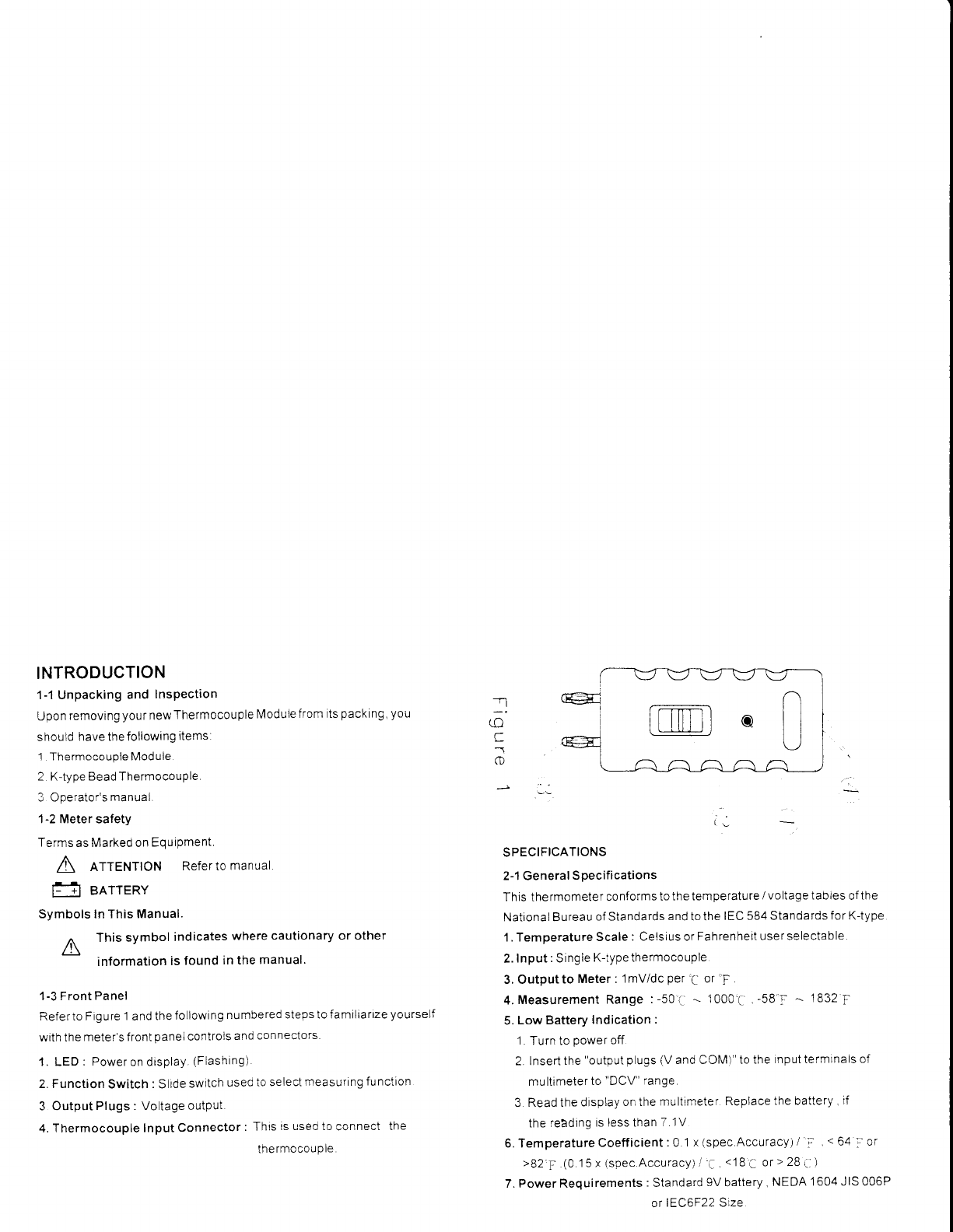
1. LED:
Poweron
display
(Flashing)
2. Function
Switch
:
Slide
switch
used
to select
measuring
functton
3 Output
Plugs : Voltage
output.
4. Thermocouple
Input
Connector
: This
is used to
connect
the
tne
rmocou
p
le.
IL
SPECIFICATIONS
2-1 General
Soecifications
This thermometer
conforms to
the temperature
/ voltage tables
of
the
National Bureau
of
Standards
and
to the
IEC
584 Standards
for K{ype
1. Temoerature
Scale
: Celsius or
Fahrenheit
user selectable.
2.
Input
:
Single
K-type thermocouple
3. Output
to Meter :
1mV/dc
per
C
or
'F
4.
Measurement
Range
:-50'a
- 1000'C
,
-58
1 - 1832
F
5.
Low Battery
Indication
:
1.
Turn to
power
off.
2. lnsert
the
"output
plugs (V
and COM)" to
the
input terminals
of
multimeter
to
"DCV"
range.
3 Read the
display
on the
multimeter
Replace
the battery .
if
the
readrng
is less than
7.1V
6.TemperatureCoefficient
:
0.1
x
(spec.Accuracy) / i, t 64
a
or
>82'F.(0.15x
(spec.Accuracy)/'a,
<18
; ort
28,,-
)
7. Power Requirements
:
Standard
9V
battery
,
NEDA
1604 JIS 006P
]
(o
C
o
or
lEC6F22
Size
8.
Battery
Life:
Alkaline 30C
hours
9. Dimensions
: 122mm(L)x
46mm1W)
x
30mmlDr
'l0.
Weight
(including battery)
:
1
.14
grns
11. Accessories
:
K
-
type bead thermocoup
e battery ilnsialied),
operator's
manual.
2-2
Environmental Conditions
'1
. Indoor Use.
2 Operating
Ambient:
O% to
80920 R H i0
to
35
,.'
i 0''6
to 70%
(35to50')RH
3. Storage
Temperature
:
-20
,- - 60
,'-
C
to E0o,'6 R.H. with baitery
removed from
meter
2-3
Electrical
Specifications
Measurement
Range Accuracy Input
Protection
-50,'
'- -20
_- (2.]o./c
rdg
+ 2:.
60Vdc & 24Vrms
:(2.04/"rg+4r)
-19i-
- 350i' 1O 59/ordg
+ 2 '-.
1
-Jf --ooz.' r0S%rdg+4F)
351. --
500i (2
aohrdg
+
l' i
663
r: -- 932 (2.0o/ordg+4;)
501'r'
--
1000'i -
i2.gah
rdg
+
2';1
933
I -' 1832'l (29o'6rdg+4:1
Thermocouple
Characterrstics
K-Type
Thermocouple
50BK bead
thermocouple
Temperature
Range:
-40
" to
2A4, l4A r: to 399.2'|
).
Toferances:
- (.2.2';
or075%tfrom
0:'b2A4 .. ::
14.0For075%)
from 32
| to
399 2 ::
: (,2.2'i,
or ?.Aok\
from
-40
- to 0
a i4.0
T or 0.75%)
from -40
I to 32'ii
Wire Length
:
1m,
wrth
miniature
plug.
Teflon
tape
tnsulated.
3-2 Temperature Measurements
1.
Connect
lhe olug
ofthe thermocoupie
to the connector
cf ihe
thermometer
Seiect
the
'-
i J iunction
desired.
lnsert
the
'Output
PIugs
t/
and COful
,' to lhe nput termlnals
iV
anC
COM)
cf
Multimeter
Obsen.,e
the
procer
pclar';tv
rf reading'rvill
be
Inaccu rate.
4 Set the
l\,4ultimetelio
"DC
;."rV
or
V" range
5.
Use the
sensing
point
of
thermoccuple
lo measure the sunace
to be
i'neasu
red.
6 Read the
stable
reading
7.
"Warning'
. Do not
rneasure
rhe sudace
that the
potential
exceeds
60V d.c.
or
24V
r.m.s.
MAINTENANCE
A ro AVorD
ELEcTRTcAL
sHocK
REMovE TEST
THERMo-
COUPLE
BEFORE
OPENING
THE
COVER,
4-1 General
Maintenance
1
.
To keep the
instrument
clean,wipe
the case
with a dry cloth
and
detergent,
do
not use abraslves
or solvents
2 Any adrusiment
matntenancs
2n6
1sp3rr
shatl
be by a sktlled
person
about temperature
technology
To maintatn a thermocouole
tn
good
condition ,
shall
observe
the
following
itemes
- Avoid
excess
bendrno
- Don't
overheat
the
thermocouoie.
- Avoid
chemical
reactions
that can damage
the
thermocouple
4-2
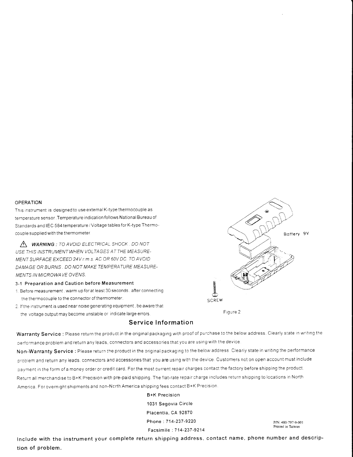
Battery
Replacemenl
The
meter
is
powered
by
a alkaline
9V battery
Referto
Figure
2 and use
the
forlowing
orocedure
to
reolace the
battery
.l
. Disconnect
the
output
plugs
and turn
the meter
off.
Remove the
con-
nector
of
the thermocouple
from connector
of the
meter'
2.
Positio
n the
meter
face down.
Remove
the screw
f rom the bottom
3. Remove
the bottom
case
4 Carefullydisconnectthe
battery
from bottom case
5 Replace
with a
new 9V
battery and
reinstallthe bottom
case
and screw
3
OPER,ATION
This
nstrumeni
is designed
to
use externalK{ype
thermocouple
as
temDerature
sensor
.Temperature
indication
follows
National Bureau of
Sta
ndards and
IEC 584 temperature
/ Voltage
tables
for K-type Thermo-
couple
supplied
with the thermometer
A SARNING
: To AVCTD ELECTR:]A:-
sHccK Do Nor
USE
THIS
INSTRIJMENT
WHEN
VOI-TAGES
AT THE MFASURE-
MENT SURFACE
EXCEED
24V
T.M.S,
AC OR 6OV DC.
TO
AVCID
DAMAGE
OR BURIVS
. DA NAT
MAKE TEMFERATURE
MEASURE-
MENTS
IN MICROWAVE
OYF/VS,
3-1
Preparation
and
Caution before
Measurement
1 Before
measurement
. warm
up for at least 30
seconds . after connecting
tne thermocouple
to
the connector
of thermometer.
2 lf tne
rnstrument is used
near
noise
generating
equipment.
be
aware that
the
voltage output may
become
unstable
or
indicate large errors.
EotlerY 9V
Service Information
Warranty
Service
: Please
return
the
product
in the original
packaging
with
proof
of
purchase
to the below address. Clearly
state
1n wrrtrng the
oerforrrance
problem
and
return any
leads,
connectors and accessories that
you
are
using
with
the device
Non-Warranty
Service
: Please
return the
product
in the orrgrnaipackagrng
to
the belo$'address
Cleariy state
in writing the
Derformance
proclemandreturnanyleads.connectorsandaccessoriesthat
youareusingwiththedevice.Customersnotcnopenaccountmustinclude
pavirrent
in
the
f
orm of
a money
order or
credii
card. For the most
current
repair
charges
contact the
factory
bef ore shipprng
the
product.
Return allmerchandrse
to
B+K
Precision
with
pre-paid
shipping The
flat-rate
repaircharge
includes
return
shipping to
locations
n North
America.
For
overnight
shioments
and
non-Ncrth
America
shipprng fees contact
B+K
Precision.
B+K Precision
1031
Segovia
Circle
Placentia, CA
92870
Phone :714-237-9220
Facsimile
:
7 1 4-237
-921
4
Include
with the instrument
your complete return
shipping address. contact name,
tion of problem.
E
/E-.
Figure
2
P/l,l: 480 797-9-001
Printed in Taiwm
phone
number and descri
p-
