5492B Bench Digital Multimeter Manual
2014-04-30
: Bk 5492B Manual 5492B_manual en-us manuals s
Open the PDF directly: View PDF ![]() .
.
Page Count: 111 [warning: Documents this large are best viewed by clicking the View PDF Link!]
Model: 5492B, 5492BGPIB
5 ½ Bench Digital Multimeter
USER MANUAL
2
Safety Notice
As described in the International Electrotechnical Commission (IEC) Standard IEC 664, digital
multimeter measuring circuits (e.g., B&K Models 5492B) and the USB terminal are Installation
Category II (CAT II). All other instruments’ signal terminals are Installation Category I and must
not be connected to mains.
This equipment is a POLLUTION DEGREE 2, INDOOR USE product.
Safety Summary
The following safety precautions apply to both operating and maintenance personnel and
must be observed during all phases of operation, service, and repair of this instrument.
Before applying power, follow the installation instructions and become familiar with the
operating instructions for this instrument.
GROUND THE INSTRUMENT
To minimize shock hazard, the instrument chassis and cabinet must be connected to an
electrical ground. This instrument is grounded through the ground conductor of the
supplied, three-conductor ac power cable. The power cable must be plugged into an
approved three-conductor electrical outlet. Do not alter the ground connection. Without the
protective ground connection, all accessible conductive parts (including control knobs) can
render an electric shock. The power jack and mating plug of the power cable meet IEC
safety standards.
DO NOT OPERATE IN AN EXPLOSIVE ATMOSPHERE
Do not operate the instrument in the presence of flammable gases or fumes. Operation of
any electrical instrument in such an environment constitutes a definite safety hazard.
KEEP AWAY FROM LIVE CIRCUITS
Instrument covers must not be removed by operating personnel. Component replacement
and internal adjustments must be made by qualified maintenance personnel. Disconnect the
power cord before removing the instrument covers and replacing components. Under certain
conditions, even with the power cable removed, dangerous voltages may exist. To avoid
injuries, always disconnect power and discharge circuits before touching them.
DO NOT SERVICE OR ADJUST ALONE
Do not attempt any internal service or adjustment unless another person, capable of
rendering first aid and resuscitation, is present.
DO NOT SUBSTITUTE PARTS OR MODIFY THE INSTRUMENT
3
Do not install substitute parts or perform any unauthorized modifications to this instrument.
Return the instrument to B&K Precision for service and repair to ensure that safety features
are maintained.
WARNINGS AND CAUTIONS
WARNING and CAUTION statements, such as the following examples, denote a hazard
and appear throughout this manual. Follow all instructions contained in these statements.
A WARNING statement calls attention to an operating procedure, practice, or condition,
which, if not followed correctly, could result in injury or death to personnel.
A CAUTION statement calls attention to an operating procedure, practice, or condition,
which, if not followed correctly, could result in damage to or destruction of parts or the
entire product.
WARNING:
Do not alter the ground connection. Without the protective ground
connection, all accessible conductive parts (including control knobs) can
render an electric shock. The power jack and mating plug of the power cable
meet IEC safety standards.
WARNING:
To avoid electrical shock hazard, disconnect power cord before removing
covers. Refer servicing to qualified personnel.
CAUTION:
Before connecting the line cord to the AC mains, check the rear panel AC line
voltage indicator. Applying a line voltage other than the indicated voltage can
destroy the AC line fuses. For continued fire protection, replace fuses only
with those of the specified voltage and current ratings.
CAUTION:
This product uses components which can be damaged by electro-static
discharge (ESD). To avoid damage, be sure to follow proper procedures for
handling, storing and transporting parts and subassemblies which contain
ESD-sensitive components.

4
SAFETY SYMBOL
This symbol serves as a warning to users of the input safety ratings. Refer to the
operating instructions for details.
Electrical Shock hazard.
Chassis ground symbol.
CAT I
(1000V)
IEC Measurement Category I.
Inputs may be connected to
mains (up to 300 VAC) under
Category II overvoltage conditions.
CAT II
(300V)
IEC Measurement Category II.
Compliance Statements
Disposal of Old Electrical & Electronic Equipment (Applicable in the European
Union and other European countries with separate collection systems)
This product is subject to Directive 2002/96/EC of the European
Parliament and the Council of the European Union on waste
electrical and electronic equipment (WEEE) , and in jurisdictions
adopting that Directive, is marked as being put on the market after
August 13, 2005, and should not be disposed of as unsorted
municipal waste. Please utilize your local WEEE collection facilities
in the disposition of this product and otherwise observe all applicable
requirements.
.
5
CE Declaration of Conformity
The 5492B and 5492BGPIB meets the requirements of 2006/95/EC Low Voltage Directive and
2004/108/EC Electromagnet Compatibility Directive.
Low Voltage Directive
- EN61010-1: 2001 (2nd edition)
Safety requirements for electrical equipment for measurement, control, and
laboratory use.
EMC Directive
- EN 61326-1:2006
- EN 61326-2-2: 2006
Electrical equipment for measurement, control, and laboratory use.
6
Table of Contents
Chapter 1 General Information ..................................................................................................... 9
1.1 Feature Overview ............................................................................................................... 9
1.2 Input Power and Fuse Requirements ................................................................................. 9
1.3 Package Contents ............................................................................................................ 11
Chapter 2 Overview ........................................................................................................................ 12
2.1 Front Panel Overview ....................................................................................................... 12
2.2 Screen Display ................................................................................................................. 14
2.3 Front Panel Menu Options ................................................................................................ 14
2.4 Front Panel Menu Overview ............................................................................................. 16
2.5 Rear Panel Summary ....................................................................................................... 17
2.6 Power up .......................................................................................................................... 18
2.6.1 Power Line Connection .................................................................................................... 18
2.6.2 Power-up Sequence ......................................................................................................... 18
2.6.3 High Energy Circuit Safety Precautions ........................................................................... 19
2.6.4 Power-on Defaults ............................................................................................................ 19
2.6.5 Warm-up time ................................................................................................................... 21
Chapter 3 Basic Measurements .................................................................................................. 22
3.1 Overview .......................................................................................................................... 22
3.2 Measuring Voltage ............................................................................................................ 22
3.2.1 Connections ...................................................................................................................... 22
3.2.2 Crest factor ....................................................................................................................... 24
3.3 Measuring Current ............................................................................................................ 24
3.3.1 Connections ...................................................................................................................... 24
3.3.2 Front Panel Fuse Replacement ........................................................................................ 25
3.4 Measuring Resistance ...................................................................................................... 26
3.4.1 Connections ...................................................................................................................... 26
3.4.2 Shielding ........................................................................................................................... 27
3.5 Measuring Frequency and Period ..................................................................................... 28
3.5.1 Trigger Level and Measurement Errors ............................................................................ 28
3.5.2 Gate Time ......................................................................................................................... 28
3.5.3 Connections ...................................................................................................................... 28
3.6 Measuring Continuity ........................................................................................................ 29
3.6.1 Connections ...................................................................................................................... 29
3.6.2 Threshold resistance level ................................................................................................ 30
3.7 Testing Diode ................................................................................................................... 30
3.7.1 Connections ...................................................................................................................... 30
3.7.2 Current Range .................................................................................................................. 31
3.8 Math Functions ................................................................................................................. 32
7
3.8.1 mX+b................................................................................................................................. 32
3.8.2 Percent .............................................................................................................................. 33
3.8.3 dB Calculation ................................................................................................................... 34
3.8.4 dBm Calculation ................................................................................................................ 35
Chapter 4 Measurement Options .............................................................................................. 37
4.1 Measurement configuration .............................................................................................. 37
4.1.1 Range ............................................................................................................................... 37
4.1.2 Filter .................................................................................................................................. 38
4.1.3 Relative ............................................................................................................................. 39
4.1.4 Rate .................................................................................................................................. 40
4.2 Trigger Operations ............................................................................................................ 41
4.2.1 Trigger Model .................................................................................................................... 41
4.2.2 EXT Trig & VM Comp ....................................................................................................... 44
4.3 Buffer Operations ............................................................................................................. 44
4.3.1 Store Reading ................................................................................................................... 45
4.3.2 Recall Readings ................................................................................................................ 46
4.3.3 Buffer Statistics ................................................................................................................. 47
4.4 Limit Operations ............................................................................................................... 47
4.4.1 Enabling limits ................................................................................................................... 48
4.4.2 Setting Limit Values .......................................................................................................... 48
4.4.3 Configure Limit Beep ........................................................................................................ 49
4.5 System Operations ........................................................................................................... 49
4.5.1 Beeper Control .................................................................................................................. 50
4.5.2 Save Settings .................................................................................................................... 50
4.5.3 Restore Settings ............................................................................................................... 51
4.5.4 Display Control ................................................................................................................. 51
4.5.5 Key Sound ........................................................................................................................ 52
4.5.6 Self-test ............................................................................................................................. 52
4.5.7 Calibration ......................................................................................................................... 53
Chapter 5 Remote Operation....................................................................................................... 54
5.1 Selecting an Interface ....................................................................................................... 54
5.1.1 USB (Virtual COM) Interface ............................................................................................ 54
5.1.2 RS-232 Serial Interface .................................................................................................... 55
5.1.3 GPIB Interface (model 5492BGPIB only) ......................................................................... 55
5.2 USB & RS-232 Interface Operation .................................................................................. 56
5.2.1 RS-232 Connection .......................................................................................................... 56
5.2.2 Sending and receiving data .............................................................................................. 57
5.2.3 Selecting Baud Rate ......................................................................................................... 57
5.2.4 Selecting Parity Mode ....................................................................................................... 57
5.2.5 Selecting Terminal Character ........................................................................................... 58
5.2.6 Selecting Echoing ............................................................................................................. 58
5.2.7 Software Protocol ............................................................................................................. 59
8
5.3 GPIB Interface operation (model 5492BGPIB only) .......................................................... 60
5.3.1 GPIB Connection .............................................................................................................. 60
5.3.2 GPIB Interface Capability ................................................................................................. 61
5.3.3 GPIB Addressing .............................................................................................................. 61
5.4 Data Format ..................................................................................................................... 61
Chapter 6 SCPI Command Reference ....................................................................................... 62
6.1 Command Structure ......................................................................................................... 62
6.2 Command Syntax ............................................................................................................. 63
6.2.1 Commands and command parameters ............................................................................ 63
6.2.2 Short-form Rules ............................................................................................................... 64
6.2.3 Basic Rules of Command Structure ................................................................................. 65
6.2.4 Multiple Command Rules ................................................................................................. 65
6.2.5 Command Path Rules ...................................................................................................... 65
6.3 Command Reference ....................................................................................................... 66
6.3.1 Measurement Commands ................................................................................................ 66
6.3.2 DISPlay subsystem........................................................................................................... 70
6.3.3 CALCulate Subsystem ..................................................................................................... 70
6.3.4 SENSe subsystem command ........................................................................................... 79
6.3.5 SYSTem Subsystem ......................................................................................................... 92
6.3.6 UNIT Subsystem ............................................................................................................... 94
6.3.7 TRIGger Subsystem ......................................................................................................... 97
6.3.8 Common Commands ........................................................................................................ 99
Chapter 7 Troubleshooting Guide .......................................................................................... 100
7.1 Frequently Asked Questions ........................................................................................... 100
7.2 Error Messages .............................................................................................................. 101
Chapter 8 Specifications ............................................................................................................. 102
8.1 Technical Specifications ................................................................................................. 102
SERVICE INFORMATION ............................................................................................................ 110
LIMITED THREE-YEAR WARRANTY ..................................................................................... 110
General information
9
Chapter 1 General Information
This chapter is outlined as follows:
1.1 Feature Overview
1.2 Input Power and Fuse Requirements
1.3 Package Contents
1.1 Feature Overview
5492B is a 5½ digital multimeter with high accuracy, stability and speed. It has a 0.01% DC voltage
basic accuracy, 0.03% basic resistance accuracy and broad ranges that can measure:
- DC voltage up to 1000 V
- AC (RMS) voltage up to 750 V, or about 1000 V Peak
- DC current up to 12 A
- AC (RMS) current up to 12 A
- Two and four-wire resistance up to 120 MΩ
- Frequency from 5 Hz to 1 MHz
1.2 Input Power and Fuse Requirements
The 5492B digital multimeter can operate on 110 V or 220 V with +/- 10% tolerance at 60 Hz or 50 Hz
with +/- 5% tolerance respectively. Before powering the instrument, please check for correct power
input setup that corresponds to the line voltage to be used for operation. Note the label in the rear label,
as shown below:
AC Input
FUSE
~110 V / 60 Hz
T1AL, 250 V
~220 V / 50 Hz
T500mAL, 250 V
There are two items to check for:
1. Check that the correct fuse is placed inside the fuse box. Referring to the above table, use a 1
A fuse for 110 V/ 60 Hz operation, and 500 mA fuse for 220 V/50 Hz operation.
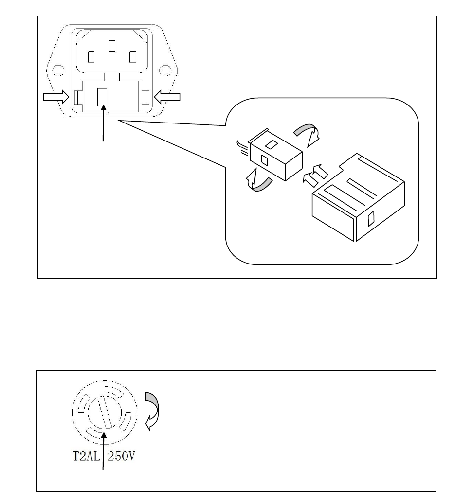
2. Check the fuse holder position. There is a voltage indicator window on the front face of the fuse
box that indicates the selected line voltage. To change or select the appropriate line voltage,
remove the fuse box and pull out and rotate the fuse holder, as illustrated below:
General information
10
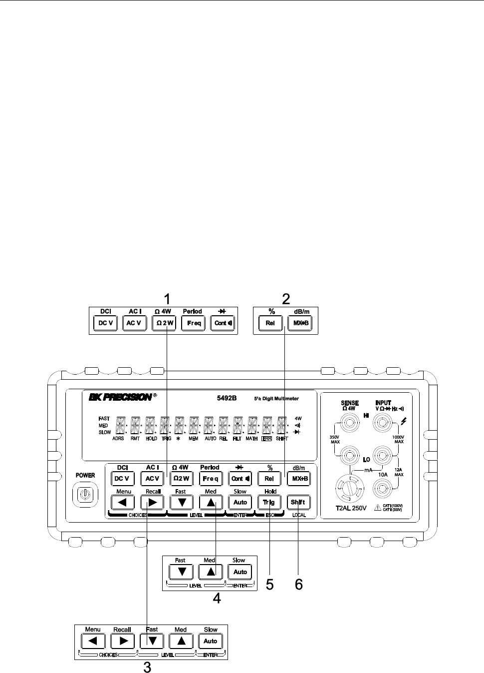
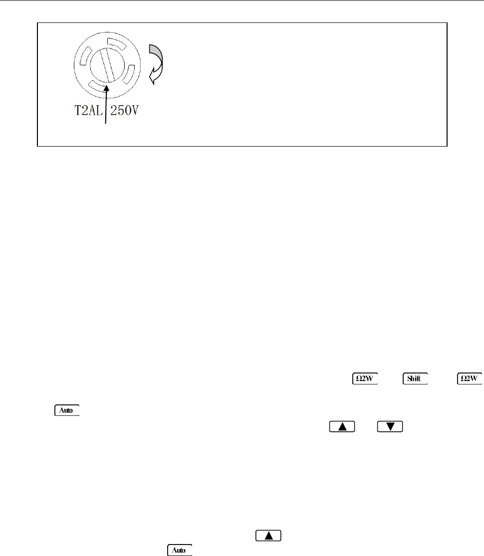
There is a second fuse with a fuse holder located in the front panel of the multimeter. This is an over
current protection fuse for the low current measurement input. It is rated for a T2AL, 250 V fuse. To
remove and replace this fuse, see the illustration below:
There is a third fuse located inside the instrument which protects the 12 A input terminal if current
exceeds the maximum rating. It is a 6 x 32 mm 250V, 20 A fast acting high energy ceramic fuse.
Fuse Box
110
To remove, use a flat head screw driver or a coin to
insert into the slid and turn counter-clockwise to
open. Similarly to put back the fuse box, push the
box down and turn clockwise.
Voltage Indicator Window
Fuse Holder
Fuse Box
110
110
220
Press both sides indicated by the arrows and pull to
remove fuse box.

General information
11
1.3 Package Contents
Please inspect the instrument mechanically and electrically upon receiving it. Unpack all items from
the shipping carton, and check for any obvious signs of physical damage that may have occurred
during transportation. Report any damage to the shipping agent immediately. Save the original
packing carton for possible future reshipment. Every meter is shipped with the following contents:
- 5492B/5492BGPIB 5½ digit multimeter
- TL35B Test Leads (one set)
- AC Power cord
- Spare fuses
- User Manual
- USB Cable
- Certificate of Calibration and Test Report
Verify that all items above are included in the shipping container. If anything is missing, please
contact B&K Precision.
Overview
12
Chapter 2 Overview
This chapter is outlined as follows:
2.1 Front Panel Overview
2.2 Screen Display
2.3 Front Panel Menu Options
2.4 Front Panel Menu Overview
2.5 Rear Panel Summary
2.6 Power up
2.1 Front Panel Overview
The front panel of the B&K 5492B is shown in Figure 2-1. This figure includes some important
abbreviated information that should be reviewed before operating the instrument.
Figure 1 - Front Panel View
Overview
13
1. Measurement function keys
Select measurement function: DC voltage and current, AC voltage and current, 2-wire and 4-wire
resistance, frequency, period, continuity and diode test.
2. Math function keys
Select math function: mX+b, %, dB, dBm and Rel.
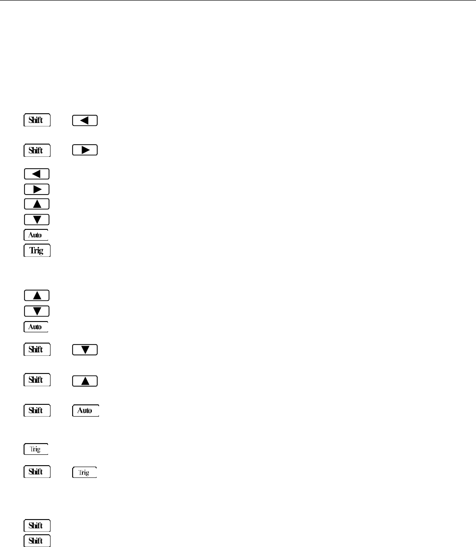
3. Menu operation keys
→ Open/Close menu
→ Recall the menu performed last
Move through selections within menu level, sub-menu level or parameter level
Move through selections within menu level, sub-menu level or parameter level.
Move up a level.
Move down a level.
(ENTER) Save the changes made on “parameter” level, and return to the “sub-menu” level.
(ESC) Cancel the changes made on “parameter” level, and return to the “sub-menu”
level.
4. Range and measurement speed keys
Select a higher range and disable auto ranging.
Select a lower range and disable auto ranging.
Toggle between auto ranging and manual ranging.
→ Set measurement speed to Fast.
→ Set measurement speed to Medium.
→ Set measurement speed to Slow.
5. Trig/Hold Key
Trigger a measurement from the front panel.
→ Hold a stable reading on the display when selected numbers of samples are
within the selected tolerance.
6. Shift/Local keys
Used to access shifted keys (labels are in blue).
(LOCAL) Exit remote operation and set back to local operation.

Overview
14
2.2 Screen Display
Figure 2-2 Display Annunciators
* (asterisk) Instrument is ready to store readings (when in system menu) /
Reading is being stored (when in measurement mode)
(Diode) Instrument is in diode testing function
(Speaker) Beeper on for continuity testing function
4W Multimeter is in 4-wire resistance measurement mode.
ADRS Multimeter is addressed to listen or talk over the GPIB interface
AUTO Auto ranging enabled
ERR Hardware or remote control error detected
FAST Fast reading rate
FILT Digital filter enabled
HOLD Reading HOLD is enabled
MATH A math operation is enabled (mX+b, %, dB, dBm).
MED Medium reading rate
MEM Turns on when reading memory is enabled
REL Relative reading displayed
RMT Multimeter is in remote mode
SHIFT Accessing shifted keys
SLOW Slow reading rate
TRIG Multimeter is waiting for a trigger (manual, bus, or external trigger).
2.3 Front Panel Menu Options
A : MEASurement MENU
1:CONTINUITY → 2:FILTER → 3:FILT TYPE → 4:FILT COUNT
1. CONTINUITY Select the continuity beeper threshold: 1 Ω to 1000 Ω
2. FILTER Enable or disable FILTER function.
3. FILT TYPE Select the type of filter.
Select MOVNG AV (Moving Average) or REPEAT (Repeating Average).
4. FILT COUNT Set the number of readings to be filtered or averaged.
B : MATH MENU
1:SET M → 2:SET B → 3:PERCENT → 4:dB REF → 5:dBm REF → 6:LIMIT TEST → 7:HIGH LIMIT
→ 8:LOW LIMITT→ 9:LIMIT BEEP
1. SET M Set the scale factor M for MX+B function.
2. SET B Set the offset factor B for MX+B function.

Overview
15
3. PERCENT Set the reference value for PERCENT function.
4. dB REF Set the dB reference voltage value.
5. dBm REF Set the dBm reference impedance value.
6. LIMIT TEST Enable or disable the limit testing.
7. HIGH LIMIT Set the high limit for limit testing.
8. LOW LIMIT Set the low limit for limit testing.
9. LIMIT BEEP Set the beep mode for limit testing. Select from: NEVER, HI, IN, LO, OUT.
C : TRIGger MENU
1:TRIG MODE → 2:TRIG DELAY
1. TRIG MODE Select the trigger source.
Select IMM (Immediate), MAN (Manual), BUS, or EXT (External) trigger
source.
2. TRIG DELAY Select AUTO or MANUal trigger delay mode. Selecting manual will allow
you to specify a time interval which is inserted before a measurement.
D : SYStem MENU
1:RDGS STORE → 2:RDGS COUNT → 3:SAVED RDGS → 4:BEEP →5:SAVE CNFG
→ 6:LOAD CNFG → 7:DISPLAY → 8:KEY SOUND → 9:TEST
1. RDGS STORE Enable or disable reading memory.
2. RDGS COUNT Set the number of readings to be saved (2 to 512).
3. SAVED RDGS Recall readings stored in memory.
4. BEEP Enable or disable the beeper function
5. SAVE CNFG Save the present configuration as one of the 10 user’s settings.
6. LOAD CNFG Restore factory or one of the 10 user’s settings
7. DISPLAY Enable or disable the front panel display.
8. KEY SOUND Enable or disable the key sound when you press a key.
9. TEST Perform a complete self-test.
E : Input / Output MENU
1:GPIB ADDR → 2:INTERFACE → 3:BAUD RATE→ 4:PARITY→ 5:TX TERM→ 6:RETURN
1. GPIB ADDR Set the GPIB bus address. (0 to 31)
2. INTERFACE Select between GPIB and USB/RS232 as the remote control interface.
3. BAUD RATE Select the baud rate for USB/RS232C operation.
Select from: 115.2K, 57.6K, 38.4K, 19.2K, 9600,4800, 2400.
4. PARITY Select the parity mode for USB/RS232C operation.
Select from: NONE, EVEN, ODD.
5. TX TERM Select the terminal character for USB/RS232C communication.
Selection from: LF, CR, LFCR
6. RETURN Enable or disable echoing command strings.
F : CALibration MENU (This function is not available)
1:SECURED → 3:CAL DATE → 4:CAL COUNT
Overview
16
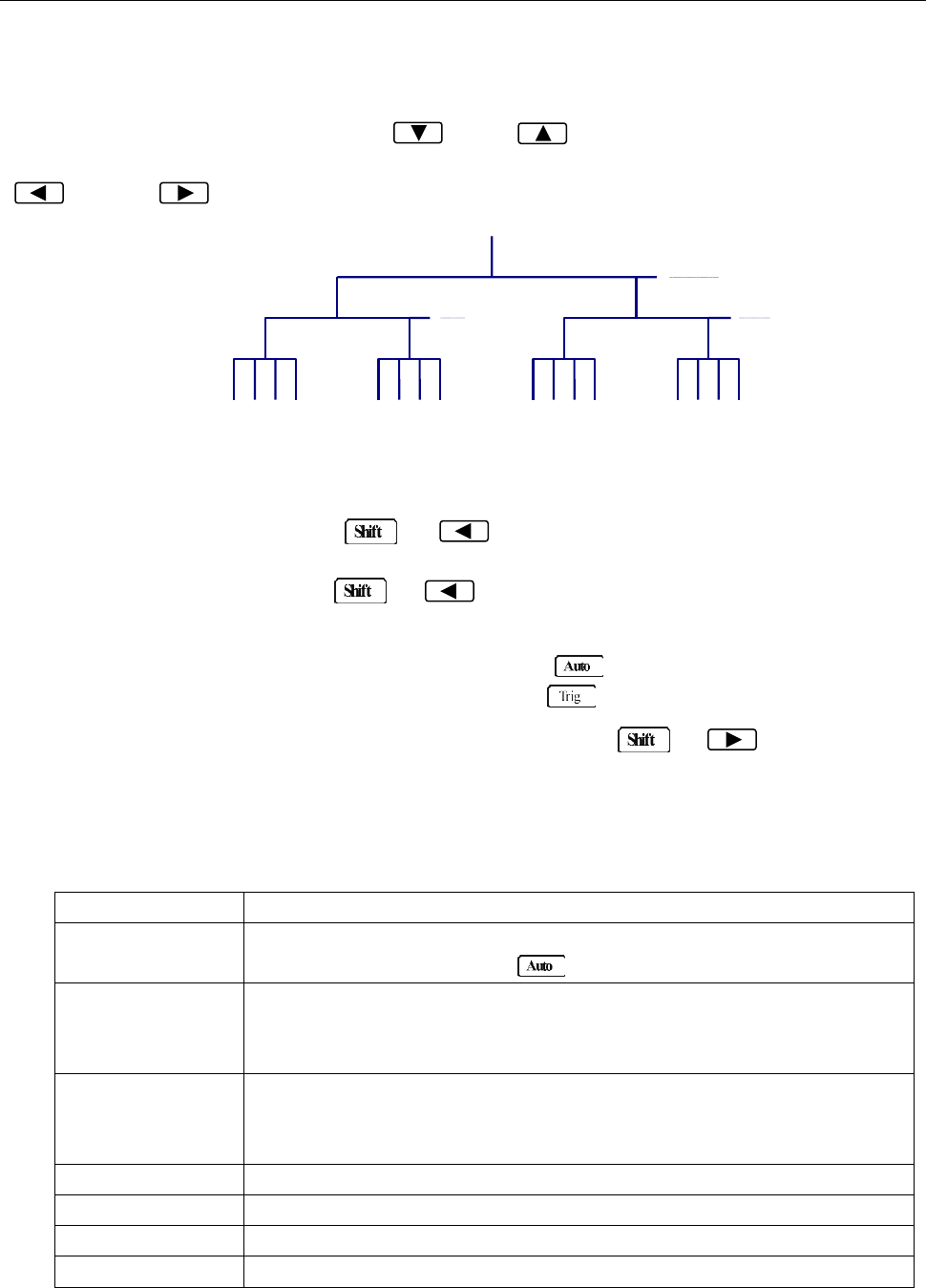
2.4 Front Panel Menu Overview
The menu is organized in a top-down tree structure with three levels (menus, submenus and parameters)
as shown in Figure 2-3. You can use down ( ) or up ( ) keys to browse through the menu tree
from one level to another. Each of the three levels has several choices which you can view by using left
( ) or right ( ) keys.
Figure 2-3 Menu Tree
- To turn on the menu, press → (Menu).
- To turn off the menu, press → (Menu), or press any of the function or math keys
on the top row of front panel keys (i.e. DC V, Freq, etc.).
- To confirm a change on the “parameter” level, press (ENTER).
- To cancel a change on the “parameter” level, press (ESC).
- To recall the last menu command that was executed, press → (Recall)
The messages displayed during menu operation are listed in the following Table 2-1.
Table 2-1 Messages Displayed During Menu Operation
MESSAGES
DESCRIPTION
CHANGE SAVED
The change made on the “parameter” level is saved. This message will
be displayed after you press (ENTER) to save the changes.
TOO SMALL
The value you specified on the “parameter” level is too small for the
selected command. The minimum value allowed is displayed for you to
edit.
TOO LARGE
The value you specified on the “parameter” level is too large for the
selected command. The maximum value allowed is displayed for you to
edit.
FILE SAVING
System configuration file is being saved.
FILE LOADING
System configuration file is being restored.
SAVE SUCCEED
System configuration file is successfully saved.
LOAD SUCCEED
System configuration file is successfully restored.
Menus
Submenus
Parameters
Overview
17
Note: If you press on the “menu” level, nothing will happen because it is at the top
menu level of already. Likewise, if you press on the “parameter” level, nothing will
happen because it is at the lowest menu level.
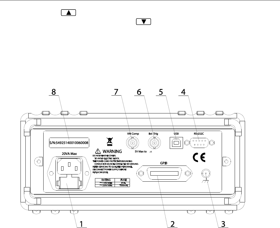
2.5 Rear Panel Summary
The rear panel of BK 5492B is shown in Figure 2-4. This section includes important information that
should be reviewed before operating the instrument.
Figure 2-4 Rear Panel
1. Power line fuse holder
The multimeters can be configured for line voltage of 110/220 V ± 10 % AC at line frequency of 50/60
Hz ± 5%.
Power line fuse is used for instrument protection. (220 V/500 mA or 110 V/1 A)
Note: Please use the same-type of fuse as it is in the fuse holder. To verify and replace the
fuse, remove the power cable and pull out the fuse holder. See section 1.2 for
details.
2. (optional) GPIB (IEEE-488) interface (model 5492BGPIB)
3. Chassis ground screw terminal
4. RS-232 (Serial) interface
5. USB interface
6. External Trigger BNC input terminal
7. VM Comp (Voltmeter complete) BNC output terminal
8. Serial number label

Overview
18
2.6 Power up
2.6.1 Power Line Connection
CAUTION: Operating the instrument on an incorrect line voltage may cause damage to the
instrument, possibly voiding the warranty.
BEFORE connecting the 5492B multimeter to a power line, please check that the correct fuse is
in place, and the fuse box inside the fuse holder is adjusted correctly. See section 1.2 for
details.
Follow the procedure below to connect the 5492B to line power and turn on the instrument.
1. Check the line voltage and be sure it is within the acceptable range of the meter BEFORE
connecting into the AC input in the rear panel of the instrument. Applying an incorrect voltage
may cause damage to the instrument and void its warranty.
2. Check the fuse box position inside the fuse holder to make sure it is in the correct position that
corresponds to the line voltage the unit will be connected to. The fuse holder will have a selected
voltage label on the front to indicate the selected voltage tab for operation. Change the fuse box
position to change between 110 and 220. If you’re not sure, see section 1.2 for details.
3. Check that the correct line fuse is properly inserted into the fuse box. The fuse rating between
110V and 220V operation is different. Refer to section 1.2 for details.
4. Before plugging in the power cord, make sure that the front panel power switch is in the off (out)
position.
5. Connect the female end of the supplied power cord to the AC input on the rear panel. Connect the
other end of the power cord to a grounded AC outlet.
WARNING: The power cord supplied with the Model 5492B contains a separate ground wire for
use with grounded outlets. When proper connections are made, instrument chassis
is connected to power line ground through the ground wire in the power cord. Failure
to use a grounded outlet may result in personal injury or death due to electric shock.
6. Turn on the instrument by pressing the front panel power switch.
2.6.2 Power-up Sequence
On power-up, the multimeter performs self-tests on its EPROM and RAM and lights all segments and
annunciators for about 1 second. If a failure is detected, the instrument momentarily displays an error
message and the ERR annunciator will turn on.
If the instrument passes self-tests, the firmware version and the model number will display momentarily
before it is ready for use.

Overview
19
2.6.3 High Energy Circuit Safety Precautions
To optimize safety when measuring voltage in high energy distribution circuits, read and use the
directions in the following warning.
WARNIG: Dangerous arcs of an explosive nature in a high energy circuit can cause severe
personal injury or death. If the multimeter is connected to a high energy circuit
when set to a current range, low resistance range, or any other low impedance
range, the circuit is virtually shorted. Dangerous arcing can result even when the
multimeter is set to a voltage range if the minimum voltage spacing is reduced in the
external connections.
When making measurements in high energy circuits, use test leads and accessories that meet the
following requirements:
Test leads and accessories must be fully insulated and adhere to proper ANSI IEC CAT ratings.
Do not use test leads or accessories that decrease voltage spacing. This diminishes arc
protection and creates a hazardous condition.
WARNING: The maximum common-mode voltage (voltage between INPUT LO and the chassis
ground) is 500 V peak. Exceeding this value may cause a breakdown in insulation,
creating a shock hazard.
2.6.4 Power-on Defaults
The multimeter uses the factory default settings for the power-on settings.
All the procedures in this manual assume factory default settings, therefore reset the instrument to the
factory settings when following the step-by-step procedures in later sections. Table 2-2 lists the factory
default settings.

Overview
20
Table 2-2 Factory Default Settings
Setting
Factory Default
Autozero
Buffer
Continuity
Beeper
Digits
Rate
Threshold
Current(AC and DC)
Digits(AC)
Digits(DC)
Filter
Count
Mode
Range
Relative
Value
Rate(AC)
Rate(DC)
Diode test
Digits
Range
Rate
Frequency and Period
Digits
Range
Relative
Value
Rate
Function
GPIB
Address
Language
Limits
Beeper
High limit
Low limit
mX+b
Scale factor
Offset
Percent
Reference
On
No effect
On
4 1/2
Fast(0.1 PLC)
10 Ω
5 1/2
5 1/2
On
5
Moving average
Auto
Off
0.0
Medium(10PLC)
Medium( 1 PLC)
5 1/2
1 mA
Medium(1 PLC)
5 1/2
12 V
Off
0.0
Slow(1 sec)
DCV
No effect
8
SCPI
Off
ON
+1
-1
Off
1.0
0.0
Off
1.0

Overview
21
Table 2-2 Factory Default Settings (cont.)
Resistance(2-wire and 4-wire)
Digits
Filter
Count
Mode
Range
Relative
Value
Rate
RS-232(USB)
Baud
Triggers
Continuous
Delay
Source
Voltage(AC and DC)
dB reference
dBm reference
Digits(AC)
Digits(DC)
Filter
Count
Mode
Range
Relative
Value
Rate(AC)
Rate(DC)
5 1/2
On
5
Moving average
Auto
Off
0.0
Medium(1 PLC)
On
9600
On
Auto
Immediate
No effect
75 Ω
5 1/2
5 1/2
On
5
Moving average
Auto
Off
0.0
Medium(10PLC)
Medium( 1PLC)
2.6.5 Warm-up time
The 5492B is ready for use after power-up sequence (boot and self test) is completed. However, to
achieve specified accuracy and stability, allow the instrument to warm up for half an hour. If the
instrument has been subjected to extreme temperatures, allow additional time for internal temperature to
stabilize
Basic Measurements
22
Chapter 3 Basic Measurements
This chapter is outlined as follows:
3.1 Overview
3.2 Measuring Voltage
3.3 Measuring Current
3.4 Measuring Resistance
3.5 Measuring Frequency and Period
3.6 Measuring Continuity
3.7 Testing Diode
3.8 Math Functions
3.1 Overview
The front panel has two rows of keys to select various functions and operations. Most keys have a
shifted function printed in blue above the key. To perform a shifted function, press (the Shift
annunciator will turn on). Then, press the key that has the desired label above it. For example, to select
the AC current function, press then press (AC I).
If you accidentally press , just press it again to turn off the Shift annunciator.
3.2 Measuring Voltage
Voltage ranges: 120 mV, 1.2 V, 12 V, 120 V, 1000 V (750 VAC)
Maximum resolution: 1 μV (on 120 mV range)
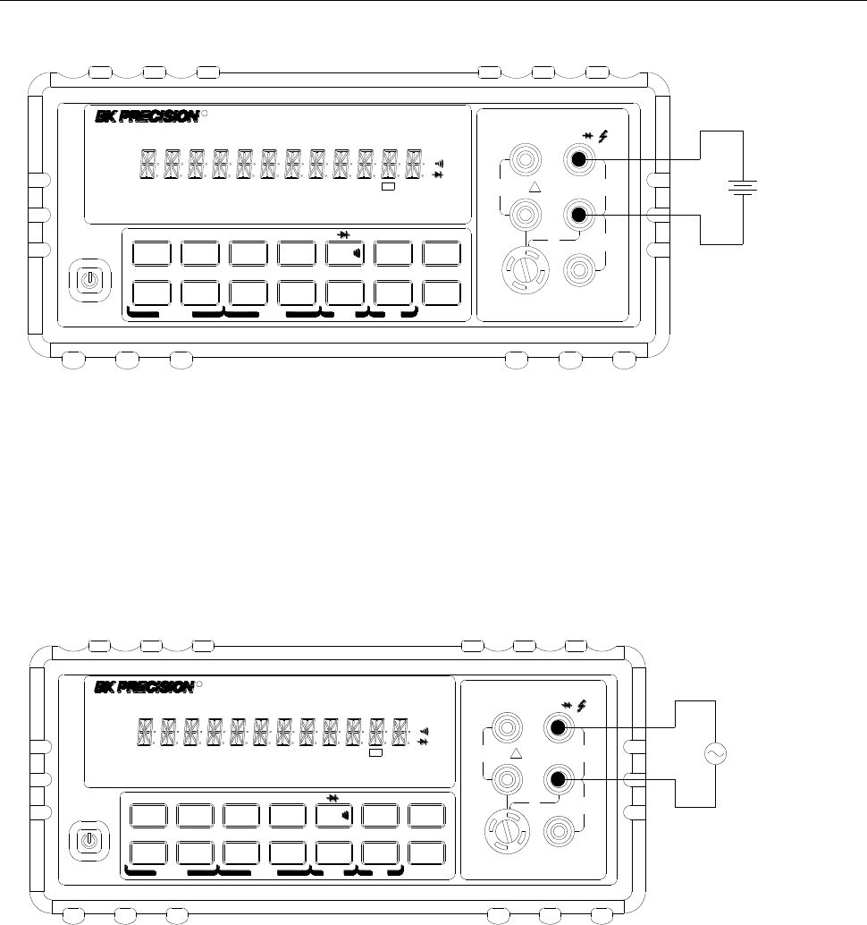
3.2.1 Connections
Assuming the multimeter is under factory default conditions, the basic procedure for measuring voltage
is as follows:
1. Connect test leads to INPUT HI and LO terminals.
2. Select DC or AC voltage measurement by pressing or respectively.
3. Press to toggle between auto and manual ranging. Notice the AUTO annunciator is
displayed with auto ranging. For manual range, use the RANGE and keys to select
the appropriate range for measurement.
4. Connect test leads to the sources as shown in Figure 3-1.
CAUTION: Do not apply more than 1000 V peak to the input or it will damage the instrument.
5. If the “OVR.FLW” message is displayed, press the up key to select a higher range until a
normal reading is displayed (or press key for auto ranging). Use the lowest possible range for
the best resolution. The measured reading is displayed.
Basic Measurements
23
DC Voltage
Source
▲
▲
▲
▲
DC V AC V 2W Freq
Aut o Tri g
MX+B
Shi f t
Cont Rel
¦¸
Period dB/m
FastMenu Recall Med Slow Hold
CHOICES LEVEL ENTER ESC LOCAL
%
IDC IAC 4W
Ω
FAST
MED
SLOW
ADRS RMT HOLD TRIG *MEM AUTO REL FILT MATH SHIFT
4W
ERR
POWER
T2AL 250V
SENSE
VΩ
LO
HI
!
10A
CATⅡ(300V)
CATⅠ(1000V)
350V
MAX
1000V
MAX
12A
MAX
mA 12A
INPUT
R5
5492B 12
/Digit Multimeter
Input Resistance = 10 MΩ on 1000 V and 120 V ranges;
> 10 GΩ on 12 V, 1.2 V and 120 mV ranges
CAUTION: Maximum Input = 1010 V peak
1000V
MAX AC Voltage
Source
▲
▲
▲
▲
DC V AC V 2W Freq
Aut o Tri g
MX+B
Shi f t
Cont Rel
¦¸
Period dB/m
FastMenu Recall Med Slow Hold
CHOICES LEVEL ENTER ESC LOCAL
%
IDC IAC 4W
Ω
FAST
MED
SLOW
ADRS RMT HOLD TRIG *MEM AUTO REL FILT MATH SHIFT
4W
ERR
POWER
T2AL 250V
SENSE
Ω4W VΩ
LO
HI
!
10A
350V
MAX
12A
MAX
mA 12A
INPUT
CATⅡ(300V)
CATⅠ(1000V)
R5
5492B 12
/Digit Multimeter
Input Impedance = 1 MΩ,100 pF
CAUTION: Maximum Input = 750 V RMS or 1000 V peak
Figure 3-1 DC and AC Voltage Measurement Connections
Basic Measurements
24
3.2.2 Crest factor
AC voltage and current accuracies are affected by the crest factor of the waveform, the ratio of the peak
value to the RMS value. Table 3-1 lists the fundamental frequencies at which the corresponding crest
factor must be taken into account for accuracy calculations.
Table 3-1 Crest Factor Limitations
Crest Factor
Fundamental Frequency
2
3
4-5
50 kHz
3 kHz
1 kHz
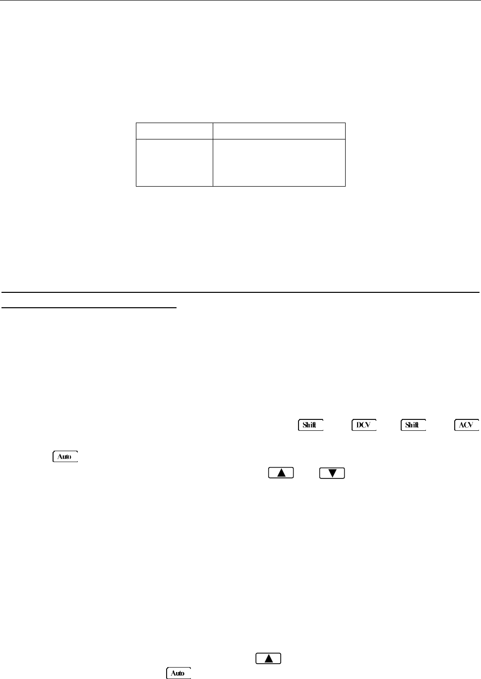
3.3 Measuring Current
Current ranges: 12 mA, 120 mA (DCI only, not available for ACI), 1.2 A, 12 A
Maximum resolution: 100 nA (on 12 mA range)
Note: Auto range is only available for 12 mA and 120 mA (DCI only) ranges. For 1.2 A and 12 A
range, manual range must be used.
3.3.1 Connections
Assuming the multimeter is under factory default conditions, the basic procedure for measuring current
is as follows:
1. Connect test leads to INPUT LO and SENSE LO terminals
2. Select DCI or ACI measurement function by pressing → or →
respectively.
3. Press to toggle between auto and manual ranging. Notice the AUTO annunciator is displayed
with auto ranging. For manual range, use the RANGE and keys to select a
measurement range consistent with expected current.
Auto range is only available for 12 mA and 120 mA (DCI only) ranges. Manual range must be
used for 1.2 A and 12 A ranges.
Therefore, it is recommended to use manual range when measuring current greater than 1 A with
1.2 A or 12 A range.
4. Connect test leads to the source as shown in Figure 3-2:
CAUTION: Do not apply more than 2 A between INPUT LO and SENSE LO terminals or the
protective fuse on the front panel will blow. Use the 10 A terminal for measuring
current above 1 A. See Figure 3-2 for details.
5. If the “OVR.FLW” message is displayed, press up key to select a higher range until a normal
reading is displayed (or press key for auto ranging). Use the lowest possible range for the
best resolution. Note that auto ranging is only available for 12 mA and 120 mA (DCI only) ranges.
Basic Measurements
25
CATⅡ(300V)
CATⅠ(1000V) 1000V
MAX
Current Source
▲
▲
▲
▲
DC V AC V 2W Fr eq
Aut o Tri g
MX+B
Shi f t
Cont Rel
¦¸
Period dB/m
FastMenu Recall Med Slow Hold
CHOICES LEVEL ENTER ESC LOCAL
%
IDC IAC 4W
Ω
FAST
MED
SLOW
ADRS RMT HOLD TRIG *MEM AUTO REL FILT MATH SHIFT
4W
ERR
POWER
T2AL 250V
SENSE
Ω4W VΩ
HI
!
10A
CATⅡ(300V)
350V
MAX
12A
MAX
mA 12A
INPUT
R5
5492B 12
/Digit Multimeter
For low current measurement: INPUT LO and SENSE LO terminals are used.
CAUTION: Maximum input = 1 A DC or RMS
1000V
MAX
12A
MAX
12A Current Source
▲
▲
▲
▲
DC V AC V 2W Freq
Aut o Tri g
MX+B
Shi f t
Cont Rel
¦¸
Period dB/m
FastMenu Recall Med Slow Hold
CHOICES LEVEL ENTER ESC LOCAL
%
IDC IAC 4W
Ω
FAST
MED
SLOW
ADRS RMT HOLD TRIG *MEM AUTO REL FILT MATH SHIFT
4W
ERR
POWER
T2AL 250V
SENSE
Ω4W VΩ
LO
HI
!
10A
CATⅡ(300V)
CATⅠ(1000V)
350V
MAX
mA
INPUT
R5
5492B 12
/Digit Multimeter
For 1 A or higher current measurement: 10 A and INPUT LO terminals are used.
CAUTION: Maximum Input = 12 A DC or RMS
Note: Auto range is not available for 1.2 A and 12 A ranges
Figure 3-2 DC and AC Current Measurements
3.3.2 Front Panel Fuse Replacement
WARNING: Make sure the instrument is disconnected from the power line and other equipment
before replacing the fuse.
1. Turn off the power and disconnect the power line and test leads.
2. From the front panel, use a screwdriver to rotate the fuse holder several turns counter-clockwise.
Take the fuse carrier out of the socket.
3. Remove the fuse and replace it with the same type (T2AL, 250 V, 5×20mm)
CAUTION: Do not use a fuse with a higher current rating than specified or instrument damage
may occur. If the instrument repeatedly blows fuses, try to find out the reason
before replacing the fuse.
Basic Measurements
26
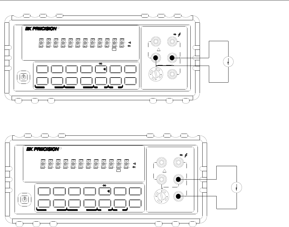
3.4 Measuring Resistance
Resistance measurement range: 120 Ω, 1.2 kΩ, 12 kΩ, 120 kΩ, 1.2 MΩ, 12 MΩ, 120 MΩ
Maximum resolution: 1 mΩ (on 120 Ω range)
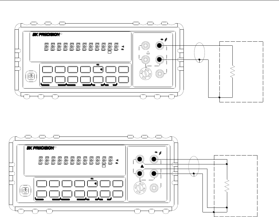
3.4.1 Connections
Assuming the multimeter is under factory default conditions, the basic procedure for measuring
resistance is as follows:
1. Connect test leads to the multimeter as follows:
A: For Ω2-wire, connect the test leads to INPUT HI and LO.
B: For Ω4-wire, connect the test leads to INPUT HI and LO, and SENSE Ω 4W HI and LO. Kelvin
test probes are recommended for this setup.
2. Select Ω 2-wire or Ω 4-wire measurement function by pressing or →
respectively.
3. Press to toggle between auto and manual ranging. Notice the AUTO annunciator is
displayed with auto ranging. For manual range, use the RANGE and keys to select a
measurement range.
4. Connect test leads to the resistance as shown in Figure 3-3:
CAUTION: Do not apply more than 1000 V peak between INPUT HI and LO or it will damage the
instrument
5. If the “OVR.FLW” message is displayed, press up key to select a higher range until a normal
reading is displayed (or press key for auto ranging). Use the lowest possible range for the
best resolution.
6. The measured reading is displayed.
Fuse Box
110
To remove, use a flat head screw driver or a coin to
insert into the slid and turn counter-clockwise to
open. Similarly to put back the fuse box, push the
box down and turn clockwise.
Basic Measurements
27
Shielded
Coble
Optional
Shield
Resistance
Under Test
▲
▲
▲
▲
DC V AC V 2W Freq
Aut o Tri g
MX+B
Shi f t
Cont Rel
¦¸
Period dB/m
FastMenu Recall Med Slow Hold
CHOICES LEVEL ENTER ESC LOCAL
%
IDC IAC 4W
Ω
FAST
MED
SLOW
ADRS RMT HOLD TRIG *MEM AUTO REL FILT MATH SHIFT
4W
ERR
POWER
T2AL 250V
SENSE
Ω4W VΩ
LO
HI
!
10A
CATⅡ(300V)
CATⅠ(1000V)
350V
MAX
1000V
MAX
12A
MAX
mA 12A
INPUT
R5
5492B 12
/Digit Multimeter
Note: Source current flows from the INPUT HI to INPUT LO terminals
T2AL 250V
SENSE
Ω4W VΩ
LO
HI
!
10A
CATⅡ(300V)
CATⅠ(1000V)
350V
MAX
1000V
MAX
12A
MAX
mA 12A
INPUT
Shielded
Coble
Optional
Shield
Resistance
Under Test
▲
▲
▲
▲
DC V AC V 2W Freq
Aut o Tr i g
MX+B
Shi f t
Cont Rel
¦¸
Period dB/m
FastMenu Recall Med Slow Hold
CHOICES LEVEL ENTER ESC LOCAL
%
IDC IAC 4W
Ω
FAST
MED
SLOW
ADRS RMT HOLD TRIG *MEM AUTO REL FILT MATH SHIFT
4W
ERR
POWER
R5
5492B 12
/Digit Multimeter
Note: Source current flows from the INPUT HI to INPUT LO terminals
Figure 3-3 Two- and Four- wire Resistance Measurements
3.4.2 Shielding
To achieve a stable accurate reading, it helps to shield resistances greater than 100 kΩ. Place the
resistance in a shielded enclosure and connect the shield to the INPUT LO terminal of the instrument
electrically.

Basic Measurements
28
3.5 Measuring Frequency and Period
Frequency measurement range: 5 Hz to 1 MHz.
Period measurement range: 0.2 s to 1 μs.
Input signal range: 120 mV AC to 750 V AC RMS.
The instrument uses the volts input terminals (INPUT HI and INPUT LO) to measure frequency and
period. The AC voltage range can be changed with the RANGE and keys. However, the
signal voltage must be greater than 10% of the full-scale range.
Note: Auto ranging is not available for frequency and period measurement function.
3.5.1 Trigger Level and Measurement Errors
Frequency and Period apply a zero-crossing trigger, meaning that a count is taken when the signal
crosses the zero level.
The multimeter uses an interactive counting technique to measure frequency and period. This method
generates constant measurement resolution for any input frequency. All frequency counters are
subject to errors when measuring low voltage, low frequency signals. Both internal noise and external
noise are also critical when measuring low voltage, low frequency signals. Measurement errors will
also occur if you attempt to measure the frequency (or period) of an input following a dc offset voltage
change. You must allow the multimeter’s DC input blocking capacitor to fully settle before making
frequency measurements.
3.5.2 Gate Time
Gate time is the amount of time the multimeter uses to sample frequency or period readings. For model
5492B, all RATE settings (Fast, Med and Slow) yield a gate time of one second.
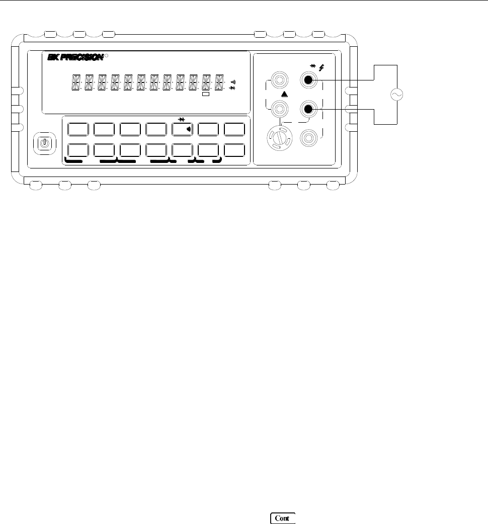
3.5.3 Connections
Assuming the multimeter is under factory default conditions, the basic procedure for measuring
frequency or period is as follows:
1. Connect test leads to INPUT HI and LO terminals.
2. Select frequency or period measurement functions by pressing or →
respectively.
3. Connect test leads to the source as shown in Figure 3-4:
CAUTION: Do not exceed 1000 V peak between INPUT HI and INPUT LO or instrument damage
may occur.
4. The measured reading is displayed.
Basic Measurements
29
T2AL 250V
SENSE
Ω4W VΩ
LO
HI
!
10A
CATⅡ(300V)
CATⅠ(1000V)
350V
MAX
1000V
MAX
12A
MAX
mA 12A
INPUT
AC Voltage
Source
▲
▲
▲
▲
DC V AC V 2W Freq
Aut o Tri g
MX+B
Shi f t
Cont Rel
¦¸
Period dB/m
FastMenu Recall Med Slow Hold
CHOICES LEVEL ENTER ESC LOCAL
%
IDC IAC 4W
Ω
FAST
MED
SLOW
ADRS RMT HOLD TRIG *MEM AUTO REL FILT MATH SHIFT
4W
ERR
POWER
R5
5492B 12
/Digit Multimeter
Input Impedance = 1 MΩ in parallel with <100 pF
CAUTION: Maximum Input = 750 RMS, or 1000 V Peak
Figure 3-4 Frequency and Period Measurements
3.6 Measuring Continuity
The multimeter uses the 1 kΩ range to measure circuit continuity. A threshold resistance level (1 Ω to
1000 Ω) should be set. The factory default value is 10 Ω. The multimeter alerts you with a beep when a
reading is below the set level.
Note: Continuity function defaults to FAST (0.1 PLC) rate and cannot be changed.
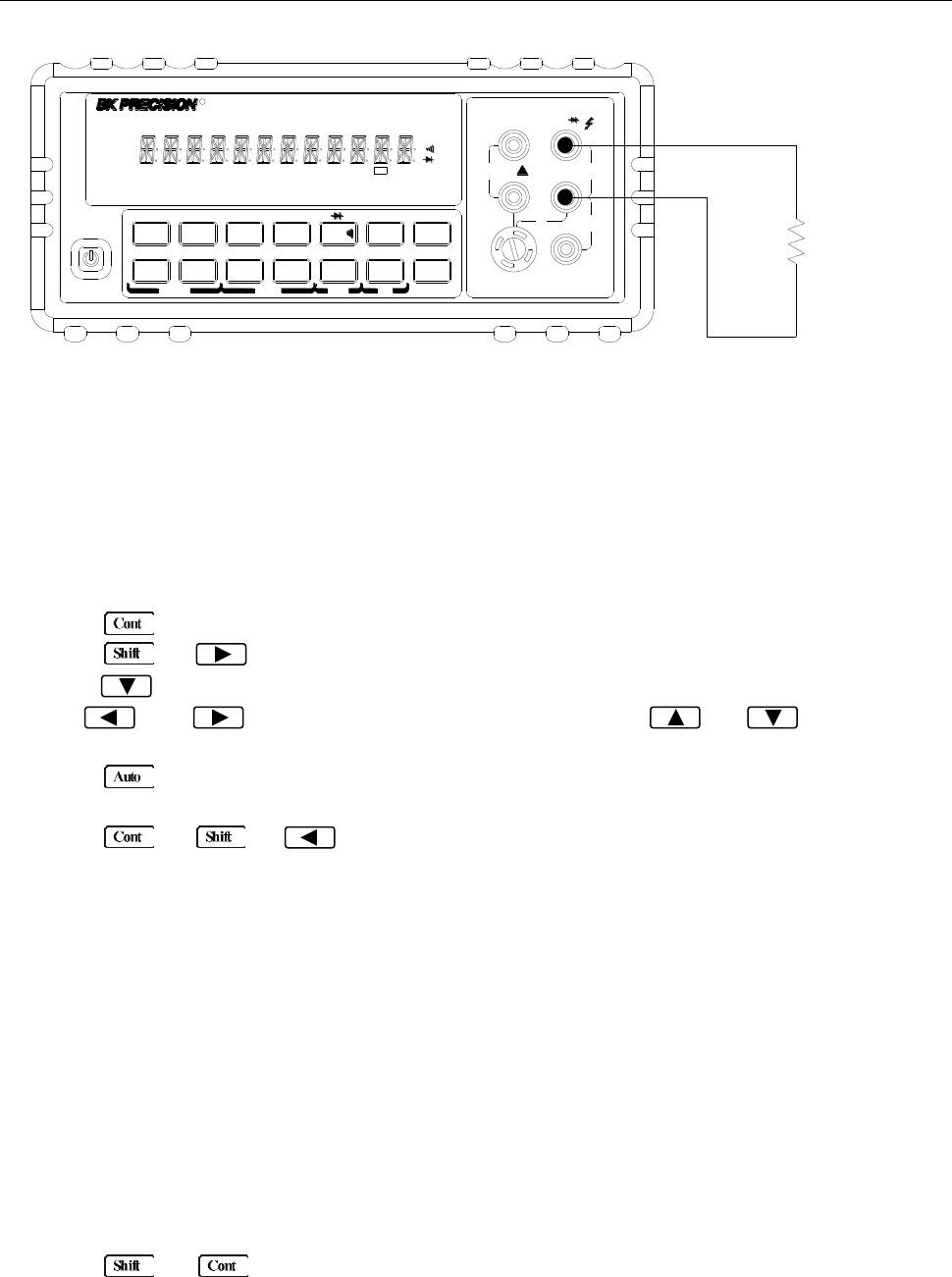
3.6.1 Connections
Assuming the multimeter is under factory default conditions, the basic procedure for continuity testing is
as follows:
1. Connect test leads to the INPUT HI and LO terminals.
2. Select Continuity measurement function by pressing .
3. Connect test leads to the resistance under test as shown in Figure 3-5.
4. The measured reading is displayed.
Basic Measurements
30
T2AL 250V
SENSE
Ω4W VΩ
LO
HI
!
10A
CATⅡ(300V)
CATⅠ(1000V)
350V
MAX
1000V
MAX
12A
MAX
mA 12A
INPUT
Resistance
Under Test
▲
▲
▲
▲
DC V AC V 2W Freq
Aut o Tri g
MX+B
Shi f t
Cont Rel
¦¸
Period dB/m
FastMenu Recall Med Slow Hold
CHOICES LEVEL ENTER ESC LOCAL
%
IDC IAC 4W
Ω
FAST
MED
SLOW
ADRS RMT HOLD TRIG *MEM AUTO REL FILT MATH SHIFT
4W
ERR
POWER
R5
5492B 12
/Digit Multimeter
Note: Source current flows from the INPUT HI to INPUT LO terminals.
Figure 3-5 Continuity Measurement
3.6.2 Threshold resistance level
You can define a threshold resistance from 1 Ω to 1000 Ω. Factory default value is 10 Ω. Follow the steps
below to define the resistance level:
1. Press for Continuity Measurement.
2. Press → to enter the submenu level, “1: CONTINUITY” will be displayed.
3. Press to enter the parameter level, the current LEVEL value will be displayed.
4. Use and keys to change the cursor position and use and keys to
increment or decrement the digits respectively. Enter a value from 1 to 1000.
5. Press (ENTER) to confirm your setting. Message “CHANGE SAVED” will be displayed for a
moment.
6. Press or → to exit the menu and return to the continuity measurement.
3.7 Testing Diode
The multimeter can also be used to measure the forward voltage drop of general-purpose diodes and
zener diodes. A current range (1 mA, 100 μA, or 10 μA) can be selected for diode measurement.
Note: Diode testing defaults to MED (1 PLC) rate and cannot be changed.
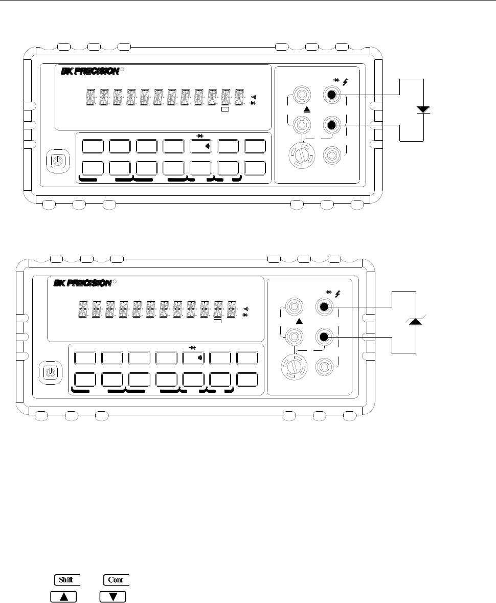
3.7.1 Connections
Assuming the multimeter is under factory default conditions, the basic procedure for diode testing is as
follows:
1. Connect test leads to INPUT HI and LO terminals.
2. Press → for diode measurement function.
3. Connect test leads to the diode under test as shown in Figure 3-6.
4. Take a reading from the display.
Basic Measurements
31
T2AL 250V
SENSE
Ω4W VΩ
LO
HI
!
10A
CATⅡ(300V)
CATⅠ(1000V)
350V
MAX
1000V
MAX
12A
MAX
mA 12A
INPUT
Diode
▲
▲
▲
▲
DC V AC V 2W Freq
Aut o Tri g
MX+B
Shi f t
Cont Rel
¦¸
Period dB/m
FastMenu Recall Med Slow Hold
CHOICES LEVEL ENTER ESC LOCAL
%
IDC IAC 4W
Ω
FAST
MED
SLOW
ADRS RMT HOLD TRIG *MEM AUTO REL FILT MATH SHIFT
4W
ERR
POWER
R5
5492B 12
/Digit Multimeter
T2AL 250V
SENSE
Ω4W VΩ
LO
HI
!
10A
CATⅡ(300V)
CATⅠ(1000V)
350V
MAX
1000V
MAX
12A
MAX
mA 12A
INPUT
Zener
diode
▲
▲
▲
▲
DC V AC V 2W Freq
Aut o Tri g
MX+B
Shi f t
Cont Rel
¦¸
Period dB/m
FastMenu Recall Med Slow Hold
CHOICES LEVEL ENTER ESC LOCAL
%
IDC IAC 4W
Ω
FAST
MED
SLOW
ADRS RMT HOLD TRIG *MEM AUTO REL FILT MATH SHIFT
4W
ERR
POWER
R5
5492B 12
/Digit Multimeter
Note: Source current flows from the INPUT HI to INPUT LO terminals
Figure 3-6 Diode Measurement
3.7.2 Current Range
You can set the test current range from the front panel. The choices are 1 mA, 100 μA, and 10 μA. The
factory default current range is 1 mA. To set the test current, follow the steps below:
1. Press → for diode measurement function
2. Using and keys to scroll through the three test current selections.
The diode test function measures voltage on the 3V range for the 1 mA test current and the 10 V range
for the 100 μA and 10 μA ranges. If a reading is more than 10V, the multimeter will display the
“OVR.FLW” message.
Basic Measurements
32
3.8 Math Functions
The multimeter math operations are divided into four categories:
mX+b and percent
dB and dBm calculations
Statistics of buffered readings
Limit testing
The first two categories are discussed here in this section, while buffered reading statistics and reading
limit testing are described in the next chapter, “Measurement Options”.
Notes: Once math is enabled for a function, the mX+b and percentage calculations will take
effect across function changes.
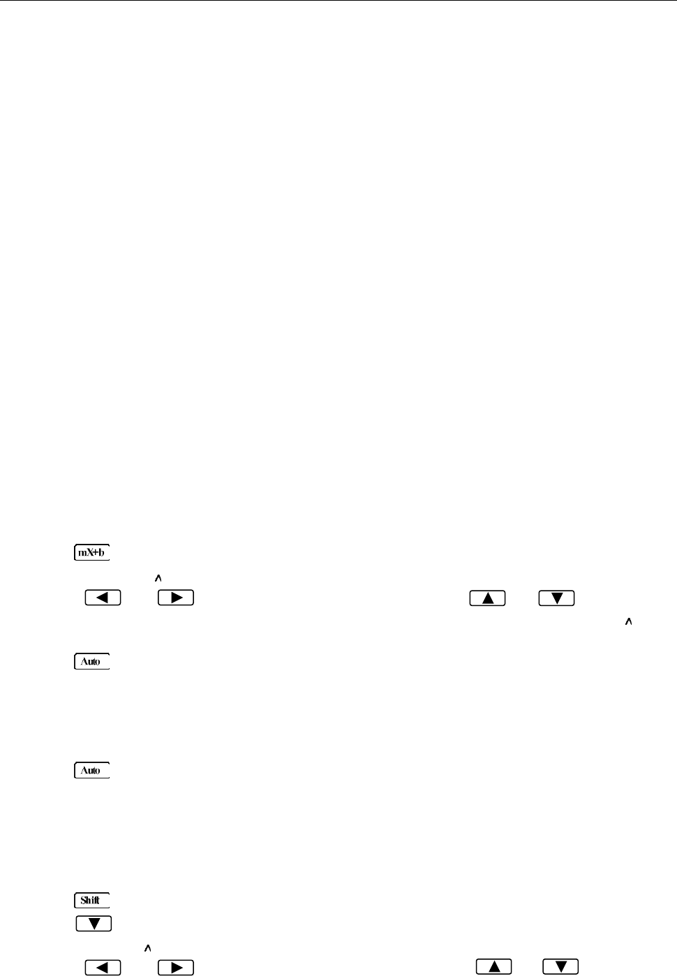
3.8.1 mX+b
This math operation lets you manipulate normal display readings (X) mathematically according to the
following calculation:
Y = mX + b
Where: X is the normally display actual reading
m and b are user-entered constants for scale factor and offset respectively
Y is the displayed result
To configure the mX+b calculation, perform the following steps:
1. Press for mX+b math operation and the present scale factor M will be displayed:
M: +1.00000
2. Use the and keys to select the cursor position and use and keys to
increment or decrement the selected digits respectively. When the cursor position selects “ ”, the
up and down arrow keys can be used to move the decimal place left or right of its current position.
3. Press (ENTER) to confirm the M value and the message “CHANGE SAVED” will be displayed
for a moment and then the present B value will be displayed. “m” is the default unit and represents
milli (10-3).
B: +0.00000 m
4. Enter a value using the arrow keys, similar to step 2 above.
5. Press (ENTER) to confirm the B value, “CHANGE SAVED” will be displayed.
6. The multimeter then returns back to the main display and will now show the results of the mX+B
calculation. The right of the display will show MXB.
If you want to change the M and B parameter values after enabling the math function at any time, you
can also do the following:
1. Press → , “1: SET M” will be displayed (Submenu level).
2. Press key to enter the parameter level and the present scale factor M will be displayed:
M: +1.00000 .
3. Use the and keys to select the cursor position and use and keys to
Basic Measurements
33
increment or decrement the digits respectively. When the cursor position selects “ ”, the up and
down arrow keys can be used to move the decimal place left or right of its current position.
4. Press (ENTER) to confirm the M value and the message “CHANGE SAVED” will be displayed
for a moment and then multimeter returns back to the submenu level. Press (ESC) to cancel
the M value input, and the multimeter will return back to the submenu level without changing the M
value.
5. Press , “2: SET B” will be displayed (Submenu level).
6. Press key to enter the parameter level and the present offset factor B will be displayed:
B: +00.0000 m.
7. Use the and keys to select the cursor position and use and keys to
increment or decrement the digits respectively. Enter a value using the arrow keys.
8. Press (ENTER) to confirm the B value. The message “CHANGE SAVED” will be displayed for
a moment and then the multimeter will return back to the submenu level. Press (ESC) to
cancel the B value input, and the multimeter will return back to the submenu level without changing
the B value.
9. Press → to exit the menu operation and return back to the mX+b calculated display.
3.8.2 Percent
When selecting the percent calculation function, a reference value must be specified. The displayed
reading will be expressed as the percent deviation from the reference value. The percentage calculation
is performed as follows:
Where: Input is the normally display actual reading
Reference is the user-entered constant
Percent is the displayed result
To configure the percent calculation, perform the following steps:
1. Press → for percent math operation and the reference value will display as:
REF: +1.00000
2. Use the and keys to select the cursor position and use and keys to
increment or decrement the digits respectively. When the cursor position selects “ ”, the up and
down arrow keys can be used to move the decimal place left or right of its current position.
3. Press (ENTER) to confirm the reference value. The message “CHANGE SAVED” will be
displayed for a moment.
4. The multimeter will display the result of the percent calculation.
If you want to change the parameter values when the percent math function is enabled, you can also do
the following:
1. Press → to enter the submenu level, “3: PERCENT” will be displayed.
2. Press to enter the parameter level, and the reference value will be displayed:
REF: +1.00000 .
3. Use the and keys to select the cursor position and use and keys to
increment or decrement the digits. Enter a value. When the cursor position selects “ ”, the up and
Basic Measurements
34
down arrow keys can be used to move the decimal place left or right of its current position.
4. Press (ENTER) to confirm the reference value, “CHANGE SAVED” will be displayed for a
moment, and the multimeter will return to the submenu level. Press (ESC) to cancel the
reference value input, and the multimeter will go back to the submenu level without changing the
reference value.
5. Press → key to exit the menu and return to the percent math operation.
The multimeter will display measurement result of the percent calculation. If the value of “Input” is larger
than that of “Reference”, displayed result will be positive. Contrarily, it will be negative if the value of
“Input” is smaller than that of “Reference”.
3.8.3 dB Calculation
The 5492B can express AC and DC voltages in dB units. The relationship between dB and voltage is
defined by the following equation:
Where: VIN is the DC or AC input signal
VREF is the specified voltage reference level
The instrument will read 0dB when the reference voltage level is applied to the input.
If a relative value is in effect when dB is selected, this relative value will be converted to dB value before
REL is applied. If REL is applied after dB function has been selected, dB reading will have REL applied
to it directly.
To set the reference voltage, perform the following steps:
1. Press + for dB math operation and the reference value is displayed:
REF: +0.00000
2. Use and keys to select cursor position and use and keys to increment
or decrement the digits respectively. Enter a value.
3. Press (ENTER) to confirm the reference voltage, and the message “CHANGE SAVED” will be
displayed for a moment. The multimeter will then return back to the measurement status.
4. Now the multimeter will display the result of the dB calculation.
If you want to change the parameter values when dB function is in effect, you can do the following:
1. Press → to enter the command level, “4: dB REF“ will be displayed.
2. Press to enter the parameter level, and the reference value will be displayed:
REF: +1.00000 .
3. Use and keys to select cursor position and use and keys to increment
or decrement the digits respectively. Enter a value and units prefix.
4. Press (ENTER) to confirm the reference value, the message “CHANGE SAVED” will be
displayed for a moment, and the multimeter will return to the submenu level. Press (ESC) to
cancel the reference value input, and the multimeter will return back to the submenu level without
Basic Measurements
35
changing the reference value.
5. Press → key to exit the menu and return to the dB math operation.
Notes: The dB calculation takes the absolute value of the ratio VIN/VREF. The largest negative
value of dB is -160 dB. This will accommodate a ratio of VIN = 1 µV, VREF = 1000 V.
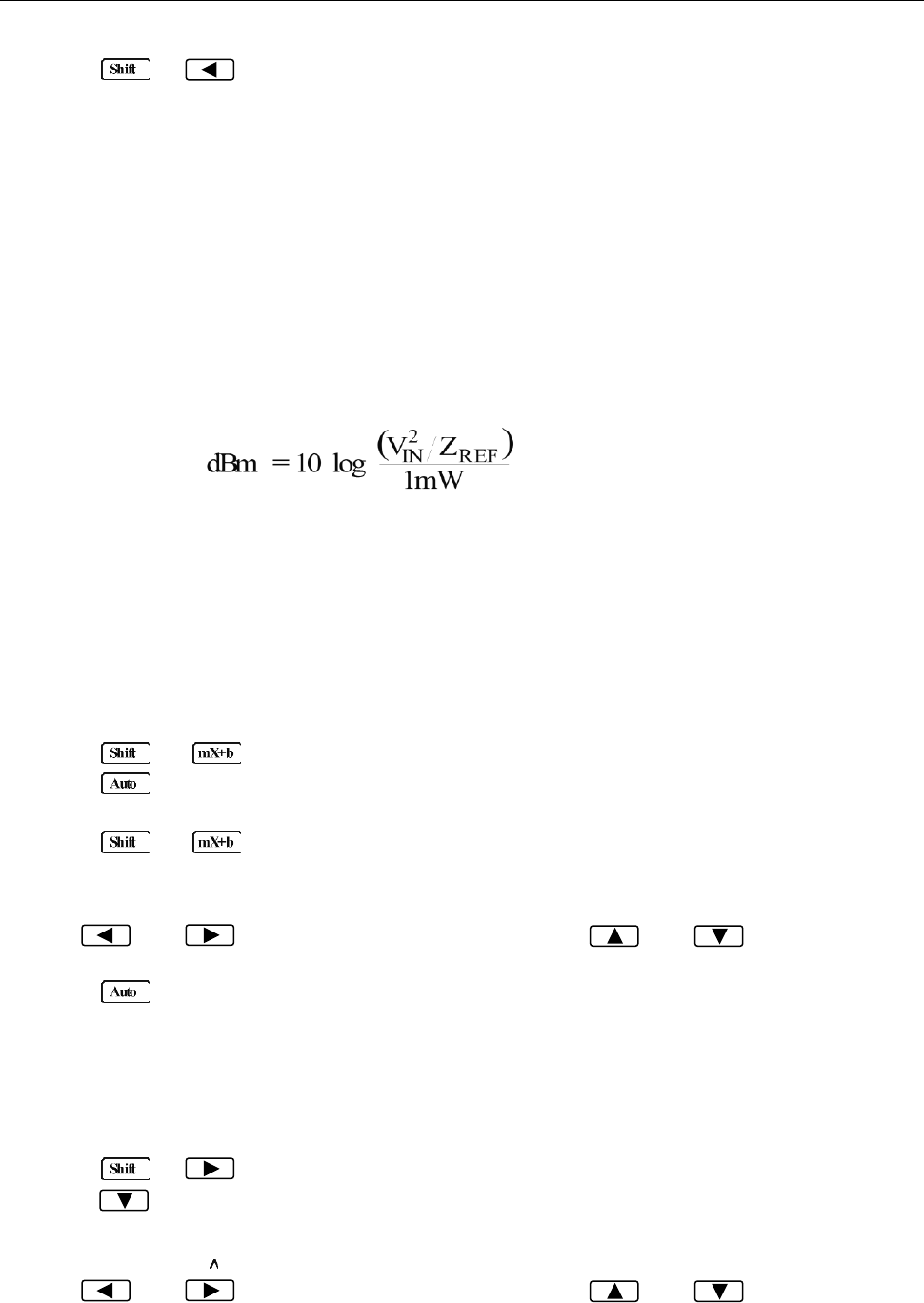
3.8.4 dBm Calculation
dBm is defined as decibels above or below a 1 mW reference. With a user-programmable reference
impedance, B&K 5492B reads 0 dBm when the voltage needed to dissipate 1mW through the reference
impedance is applied. The relationship between dBm, reference impedance, and the voltage is defined
by the following equation:
Where: VIN is the DC or AC input signal voltage value.
ZREF is the specified reference impedance.
If a relative value is in effect when dBm is selected, the relative value will be converted to dBm value
before REL is applied. If REL is applied after dBm has been selected, dBm calculation will have REL
applied to it directly.
To set the reference impedance, perform the following steps:
1. Press → , the voltage reference value for dB math function will be displayed.
2. Press (ENTER) to confirm the voltage reference value, now you have selected the dB math
function.
3. Press → again, and the impedance reference value for dBm math function will be
displayed:
REF: 0075 Ω
4. Use and keys to select cursor position and use and keys to increment
or decrement the digits respectively. Enter a value from 1 Ω to 9999 Ω.
5. Press (ENTER) to confirm the reference impedance, and the message “CHANGE SAVED”
will be displayed for a moment. The multimeter will then return back to the measurement status.
6. Now the meter will display the result of the dBm calculation.
If you want to change the impedance reference value after the dBm function is enabled, you can also do
the following:
1. Press → to enter the command level, “5: dBm REF” will be displayed.
2. Press to enter the parameter level, and the current impedance reference value will be
displayed:
REF: +1.0000
3. Use and keys to select cursor position and use and keys to increment
or decrement the digits respectively. Enter a value from 1 Ω to 9999 Ω.
Basic Measurements
36
4. Press (ENTER) to confirm the reference value, and the message “CHANGE SAVED” will be
displayed for a moment, then the multimeter will return to the submenu level. Press (ESC) to
cancel the reference value input, and the multimeter will return back to the submenu level without
changing the reference value.
5. Press → key to exit the menu and return to the dB math operation.
NOTE: The reference impedance and input impedance mentioned in this chapter are
completely different. Input impedance is inherent in the instrument and cannot be
changed via foregoing methods.
dBm is valid for both positive and negative DC voltage.
The mX+b and percent math operations are applied after the dBm or dB math
calculations. For example, if mX+b is selected with m=10 and b=0, the display will
read 10.000 MXB for a 1 VDC signal. If dBm is selected with (ZREF = 50 Ω), the display
will read 130 MXB.

Measurement Options
37
Chapter 4 Measurement Options
This chapter is outlined as follows:
4.1 Measurement configuration
4.2 Trigger Operations
4.3 Buffer Operations
4.4 Limit Operations
4.5 System Operations
4.1 Measurement configuration
4.1.1 Range
You can let the multimeter automatically select the range using auto ranging or you can select a fixed
range using manual ranging. Auto ranging is convenient because the multimeter automatically selects
the appropriate range for each measurement. However, you can use manual ranging for faster
measurements since the multimeter will not have to determine which range to use for each
measurement. The digital multimeter returns back to auto ranging when power has been off or after a
remote interface reset. Note that auto ranging is not available for some measurement functions and
ranges.
Manual ranging
To select a range, simply press or key. The instrument changes one range per key press.
The selected range is displayed momentarily before showing the measured readings.
If the instrument displays the “OVR.FLW” message on a particular range, select a higher range until an
in-range reading is displayed. Use the lowest range possible without causing an overflow to ensure best
accuracy and resolution.
Autoranging
To enable auto range, press key. The AUTO annunciator turns on when autoranging is selected.
While selected, the instrument automatically chooses the best range to measure the applied signal.
Note that up-ranging occurs at 100% of the range, while down-ranging occurs at 10 % of normal range.
To cancel auto range, press or or key. Pressing to cancel auto range will
leave the instrument in its present range.
The key has no effect on the continuity and diode test functions.
Measurement Options
38
4.1.2 Filter
FILTER lets you set the filter response to stabilize noisy measurements. The multimeter uses a digital
filter. The displayed, stored and transmitted readings are simply an average of a number of reading
conversions (from 1 to 100).
Perform the following steps to select a filter:
1. Press → to enter the menu on the menu level, “A: MEAS MENU” will be displayed.
2. Press to move down to the submenu level within the MEAS MENU, “1: CONTINUITY” will be
displayed.
3. Use or key to move across to the Filter option on the submenu level, “2: FILTER” will
be displayed.
4. Press to move down a level to the filter parameter choice.
5. Using or to turn ON or OFF the filter.
6. Press (ENTER) to confirm the selection. The message “CHANGE SAVED” will be displayed to
show that the change is now in effect. The multimeter automatically exits the parameter level and
moves up a level to the submenu level.
7. Use to move across to the filter type option on the submenu level, “3: FILT TYPE” will be
displayed.
8. Press to move down a level to the filter type parameter choice.
9. Use or to select MOVNG AV (Moving average) or REPEAT filter type.
10. Press (ENTER) to confirm the selection. The message “CHANGE SAVED” will be displayed to
show that the change is now in effect. The multimeter automatically exits the parameter level and
moves up a level to the submenu level.
11. Use to move across to the filter count option on the submenu level, “4: FILT COUNT” will be
displayed.
12. Press to move down a level to edit the filter count parameter.
13. Use and keys to select cursor position and use and keys to increment or
decrement the digits respectively. Enter a filter count from 1 to 100.
14. Press (ENTER) to confirm the count value. The message “CHANGE SAVED” will be displayed
to show that the change is now in effect. The meter automatically exits the parameter level and
moves up a level to the submenu level.
15. Press → key to exit from the menu and return to the measurement status.
16. The FILT annunciator will display when the filter function is ON.
NOTE: The filter cannot be set for frequency, period, continuity and diode test functions.
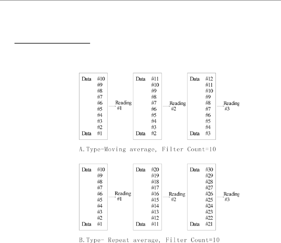
Filter Types
A. Moving Average (MOVNG AV)
The Moving average filter uses a first-in, first-out stack. When the stack becomes full, the measurement
conversions are averaged, yielding a reading. For each subsequent conversion placed into the stack,
Measurement Options
39
the oldest conversion is discarded, and the stack is re-averaged, yielding a new reading. See Figure 4-1
below.
B. Repeat Average (REPEAT)
For the repeating average filter, the stack is filled and the conversions are averaged to yield a reading.
The stack is then cleared and the process starts over as shown in Figure 4-1.
Figure 4-1 Moving average and repeating average filters
Response Time
The filter parameters have speed and accuracy tradeoffs for the time needed to display, store, or output
a filtered reading.
4.1.3 Relative
The relative operation can be used to null offsets or subtract a baseline reading from present and future
readings. When relative function is enabled, the multimeter uses the present reading as a relative value.
Subsequent readings will be the difference between the actual input value and the relative value.
You can define a relative value for each function. Once a relative value is set for a measurement function,
the value is the same for all ranges. For example, if 2 V is set as a relative value on the 12 V range, the
relative is also 2 V on the 1000 V, 120 V, 1.2 V or 120 mV ranges.
Additionally, when you perform a zero correction for DCV, Ω2 or Ω4 measurements by enabling REL, the

Measurement Options
40
displayed offset becomes the reference value. Subtracting the offset from the actual input, the display
will be as follows:
Displayed reading = Actual Input – Reference
Selecting a range that cannot accommodate the relative value does not cause an overflow condition, but
it also does not increase the maximum allowable input for that range. For example: on the 1.2 V range,
the meter still overflows for a 1.4 V input.
To set a REL value, press when the display shows the value you want as the relative value. The
REL annunciator will display. To disable REL, Press again.
You can also input a REL value manually using the mX+b function. Set M for 1 and B for any value you
want. Please refer to Chapter 3 for details about mX+b function.
4.1.4 Rate
The RATE operation sets the integration time of the A/D converter, the period of time the input signal is
measured. The integration time affects the usable digits, the amount of reading noise, as well as the
reading rate of the instrument. The integration time is specified in parameters based on a number of
power line cycles (NPLC), where 1 PLC for 50 Hz is 20 msec.
In general, the fastest integration time (FAST (0.1 PLC) set from the front panel or remote interface)
results in increased reading noise and fewer usable digits, while the slowest integration time (10 PLC)
provides the best common-mode and normal-mode rejection. In-between settings are a compromise
between speed and noise.
The RATE parameters are explained as follows:
Fast
FAST sets integration time to 0.1 PLC. Use FAST if speed is of primary importance, however it is at the
expense of increased reading noise and fewer usable digits.
Medium
Medium sets integration time to 1 PLC. Use Medium when a compromise between noise performance
and speed is acceptable.
Slow
Slow sets integration time to 10 PLC. SLOW provides better noise performance at the expense of speed.
For the AC functions (ACV, ACI), Rate setting determines the bandwidth setting as below:
Fast 500 Hz~100 kHz
Medium 50 Hz~100 kHz
Slow 5 Hz~100 kHz
Note: The integration time can be set for any measurement function except frequency, period,
continuity (FAST) and diode test (MEDium). For frequency and period, it is the equivalent
of the gate time, 1 sec.
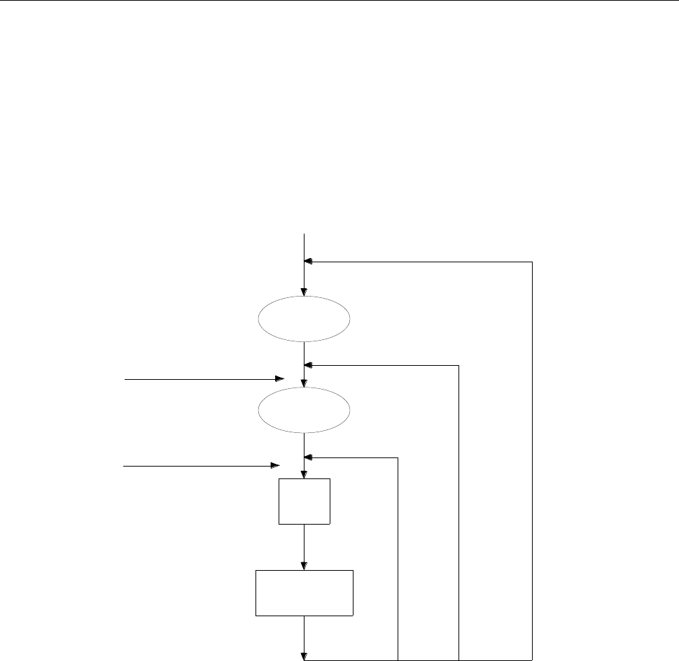
Measurement Options
41
4.2 Trigger Operations
The multimeter’s triggering system allows you to generate triggers either manually, automatically, or
externally for taking multiple readings per trigger. The following discusses front panel triggering,
programmable trigger delay, and the reading hold feature.
4.2.1 Trigger Model
The flowchart below (Figure 4-2) summarizes the triggering process of the instrument.
count≠
1
Trigger
1
≠
count
sample
MAN
BUS
IMMediate
Trigger source
Initiate Triggering
INITiate
READ?
MEASure?
sample
Measurement
Delay
Wait for
Trigger
Idle
state
Figure 4-2 Trigger model
Idle
The instrument is considered to be in the idle state whenever it is not performing any measurement.
Wait for Trigger
The control source holds up operation until the programmable event occurs and is detected. See
description below for trigger sources:
Immediate
With this trigger source, event detection happens immediately.
External
Event detection happens when either of the following takes place:
Measurement Options
42
1. A bus trigger (*TRG) command is received via remote control.
2. The front panel key is pressed (The meter must be in local mode first).
Trigger Source
The trigger source can be set from the front panel trigger menu. Users can select either IMM, MAN,
BUS, or EXT. Description of each are as follows:
IMM: Immediate. Event detection happens immediately and will continue making
measurement continuously.
MAN: Manual. Even detection happens when the front panel key is pressed. (The unit
must already be in local mode first).
BUS: Event detection happens with a bus trigger (*TRG) command is received via remote control.
EXT: Event detection happens when an external trigger signal is sent to the EXT TRIG input
terminal in the rear panel of the instrument.
To set or change the trigger source, do the following:
1. Press → to enter the menu on the menu level, “A: MEAS MENU” will be displayed.
2. Use or key to move across to the TRIG MENU on the menu level, “C: TRIG MENU” will
be displayed.
3. Press to move down to the command level within the TRIG MENU, “1: TRIG MODE” will be
displayed.
4. Press to move down a level to select the trigger source.
5. Use or to select IMM, MAN, BUS, or EXT trigger source.
6. Press (ENTER) to confirm the selection. The message “CHANGE SAVED” will be displayed to
show that the change is now in effect. The meter will then exit the parameter level and move up a
level to the command level.
7. Press → key to exit from the menu and return to the measurement display.
Delay
A programmable delay is available after event detection. It can be set manually or automatically. With
Auto delay, the meter selects a delay based on the function and range. The AUTO delay settings are
listed in Table 4-1 below.
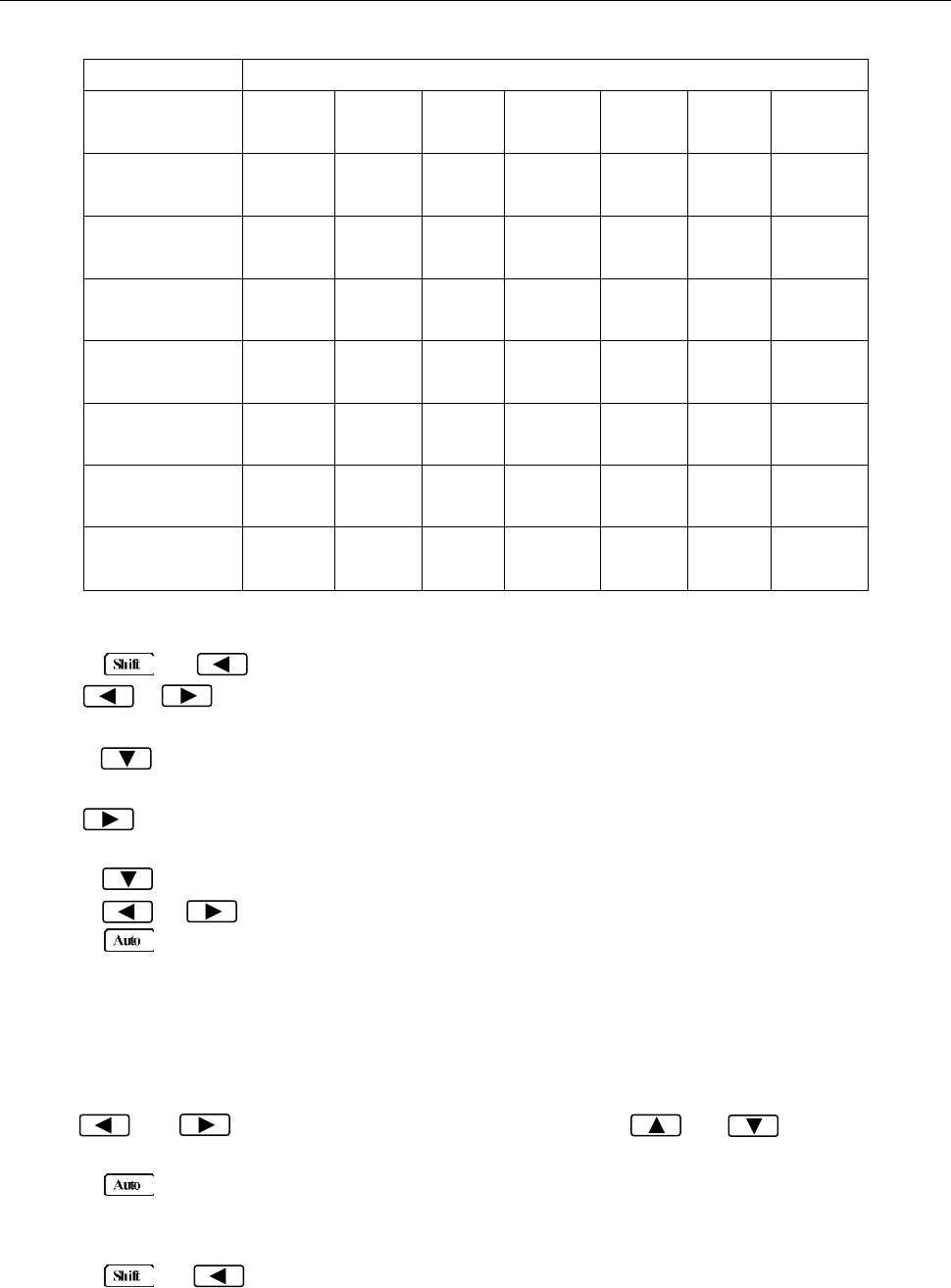
Measurement Options
43
Table 4-1 Auto delay settings
Function
Range and Delay
DCV
120mV
1ms
1.2V
1ms
12V
1ms
120V
5ms
1000V
5ms
ACV
120mV
400ms
1.2V
400ms
12V
400ms
120V
400ms
750V
400ms
FREQ
120mV
1ms
1.2V
1ms
12V
1ms
120V
1ms
750V
1ms
DCI
12mA
2ms
120mA
2ms
1.2A
2ms
12A
2ms
ACI
12mA
400ms
1.2A
400ms
12A
400ms
Ω2W, Ω4W
120Ω
3ms
1.2kΩ
3ms
12kΩ
13ms
120kΩ
25ms
1.2MΩ
100ms
12MΩ
150ms
120MΩ
250ms
Continuity
1kΩ
3ms
Diode testing
1mA
1ms
100uA
1ms
10uA
1ms
To set the delay manually, follow the below steps:
8. Press → to enter the menu on the menu level, “A: MEAS MENU” will be displayed.
9. Use or key to move across to the TRIG MENU on the menu level, “C: TRIG MENU” will
be displayed.
10. Press to move down to the command level within the TRIG MENU, “1: TRIG MODE” will be
displayed.
11. Use to move across to the TRIG DELAY command on the command level, “2: TRIG DELAY”
will be displayed.
12. Press to move down a level to set the type of delay mode.
13. Using or to select AUTO or MANU (Manual) delay mode.
14. Press (ENTER) to confirm the choice. The message “CHANGE SAVED” will be displayed to
show that the change is now in effect. If AUTO mode is selected, the multimeter will exit the
parameter level and move up a level to the command level.
15. If MANU mode is selected, a delay time will need to be specified. The screen will display like below
to show the current manual trigger delay value:
DELAY: 0000mS
16. Use and keys to choose a numerical place and use and keys to increment
or decrement the digits. Enter a value for delay time (0 to 6000 ms).
17. Press (ENTER) to confirm the delay time. The message “CHANGE SAVED” will be displayed
to show that the change is now in effect. The multimeter will automatically exit the parameter level
and move up a level to the command level.
18. Press → key to exit from the menu and return to the measurement display.
Note: Changing the trigger delay to MANU (Manual) on any function changes the same for all
other functions.
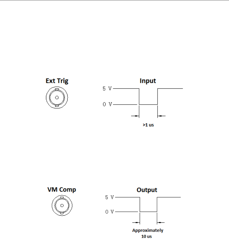
Measurement Options
44
4.2.2 EXT Trig & VM Comp
The rear panel of the instrument has two BNC terminals: Ext Trig and VM Comp. This section
describes the functionality of these two terminals.
Ext Trig
This is the external trigger input terminal. When trigger mode is set to EXT, this terminal can be used as
the source for triggering a measurement. Input a negative pulse into this terminal to trigger the
instrument. The pulse width must be greater than 1 μs. An example is illustrated in Figure 4-3 below.
Figure 4-3 Trigger model
VM Comp
This is the voltmeter complete output terminal. When the instrument completes its present measurement,
a voltmeter complete output signal will output from this terminal as shown in Figure 4-4 below. Voltmeter
complete and external trigger implement standard hardware handshaking between measurement and
switching devices.
Figure 4-4 VM Comp model
4.3 Buffer Operations
The 5492B has an internal buffer to store 2 to 512 readings. In addition, the buffer includes statistical
information based on the stored readings such as the minimum reading, maximum reading, average
based on the stored readings, and standard deviation of the stored readings (See section “4.3.3
Buffer Statistics” for details).
The buffer fills up with the requested number of readings and then stops. Readings are then placed
into the buffer and can be read back via front panel or remote operation. Buffered data is overwritten
each time the reading store function is turned enabled (ON) and initiated. The data is volatile; it is not
Measurement Options
45
saved through a power cycle.
Note: Readings will not include the function (i.e. VDC, VAC, Frequency, etc.) or the unit of
measurement (i.e. V, A, Hz, Ω, etc.) selected prior to storing into the buffer.
4.3.1 Store Reading
Select a measurement function and any math operations first, then connect the test leads to the signal
under test. Setup the reading speed (FAST, MED, SLOW), then use the following procedure to store
readings:
1. Press → to enter the menu on the menu level, “A: MEAS MENU” will be displayed.
2. Use or key to move across to the SYS MENU on the menu level, “D: SYS MENU” will
be displayed.
3. Press to move down to the command level within the SYS MENU, “1: RDGS STORE” will be
displayed.
4. Press to move down a level to set RDGS STORE function.
5. Use or key to set reading store function to ON or OFF.
6. Press (ENTER) to confirm the ON/OFF selection. The message “CHANGE SAVED” will be
displayed to show that the change is now in effect. The meter will automatically exit the parameter
level and move up a level to the command level.
7. At this time, a “*” annunciator will light up on the display (This may not light up if the number of
readings to store has not been specified or if it is 000. Continue to the next step to set this up).
This indicates that the instrument is ready to store readings into the buffer. If the user decides to
turn it off at this moment, do not exit the menu system. Instead, follow step 5-7 again, with reading
store function set to OFF in step 6.
8. Use to move across to the RDGS COUNT command on the command level, “2: RDGS
COUNT” will be displayed.
9. Press to move down a level to edit the number of readings to store into buffer.
10. Use and keys to choose a numerical place and use and keys to increment
or decrement the digits. Enter a number between 2 to 512.
11. Press (ENTER) to confirm the number of readings to store. The message “CHANGE SAVED”
will be displayed to show that the change is now in effect. The multimeter will exit the parameter
level and move up a level to the command level.
12. If you did not see a “*” indicator on display in step 7, you will see it now after the number of readings
for RDGS COUNT parameter has been set to a number (2 to 512).
13. Press → key to exit from the menu, and readings will immediately start storing into
the buffer.
14. Notice the “*” annunciator is still lid. At this point, it will stay lid until the specified number of
readings are stored into the buffer. During this time, do not push any keys to interrupt the
instrument from storing readings into the buffer.
Note: When the instrument completes the storage of readings into the buffer, the reading store
function (1: RDGS STORE) parameter within the system menu will automatically set back to OFF.
To store readings again, go into the system menu and set this parameter back to ON.
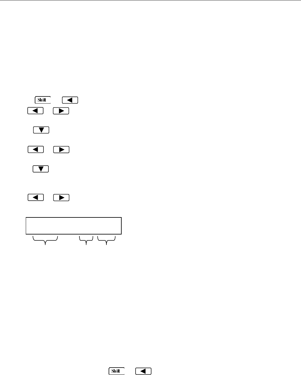
Measurement Options
46
Warning: Readings inside the buffer are volatile. Therefore do not power off the instrument or
data will be lost. Additionally, each time the store reading function is enabled and initialized,
previously stored data in the buffer will be overwritten.
4.3.2 Recall Readings
Use the following steps to recall the stored readings and their statistical information (minimum, maximum,
average, and standard deviation):
1. Press → to enter the menu on the menu level, “A: MEAS MENU” will be displayed.
2. Use or key to move across to the SYS MENU on the menu level, “D: SYS MENU” will
be displayed.
3. Press to move down to the command level within the SYS MENU, “1: RDGS STORE” will be
displayed.
4. Use or key to move across to the SAVED RDGS command, “3: SAVED RDGS” will be
displayed.
5. Press to move down a level to view the stored readings. “MEM” annunciator will turn on to
indicate the instrument accessing buffer memory. If no readings are stored, a “BUFFER EMPTY”
message will be displayed for a few seconds.
6. Use or key to navigate through the readings. The display may look like any of the
following when browsing through all the stored readings:
7. Use the function keys or press → to exit from the menu and return to measurement
mode.
Warning: Readings inside the buffer are volatile. Therefore do not power off the instrument or
data will be lost. Additionally, each time the store reading function is enabled and initialized,
previously stored data in the buffer will be overwritten.
1.234 m:005
Reading
Unit
Prefix
Reading # or type of
statistical information
Reading: Stored reading value
Unit Prefix: The unit prefix that applies
to the Reading. This can be m (10-3), u
(10-6), n (10-9), or blank.
Reading # or type of statistical
information: Indicates the reading # or
count that corresponds to the Reading.
This can be any number from 001 – 512.
Additionally, this can display the type of
statistical information in which the
Reading corresponds with. This can be
MAX, MIN, AVG, or STD (See section
“4.3.3 Buffer Statistics” for details).

Measurement Options
47
4.3.3 Buffer Statistics
In addition to measured readings that can be stored into the internal buffer, four other statistical
information of the stored readings are also kept inside the buffer. They are: MAX, MIN, AVG, STD.
MAX and MIN
The MAX and MIN refer to the maximum and minimum value of the readings stored in the buffer
respectively.
For example, suppose the buffer contains the following five readings: 1.234, 2.345, 3.456, 4.567, 5.678.
MAX = 5.678
MIN = 1.234
AVR
AVR stands for average. The AVR value is the mean(average) of the buffered readings. The equation
used to calculate this is:
Where: is a stored reading
is the number of stored readings
For example, suppose the buffer contains the following five readings: 1.234, 2.345, 3.456, 4.567, 5.678.
AVG = 3.456
STD
The STD value is the standard deviation of the buffered readings. The equation used to calculate the
standard deviation is:
Where: is a stored reading
is the number of stored readings
4.4 Limit Operations
Limit operations set and control the values that determine the HI / IN / LO status of subsequent
measurements. Limits can be applied to all measurement functions except continuity. The limit test is
performed after mX+b and percent math operations. Unit prefixes are applied before the limit test, for
example:
Low Limit = -1.0, High Limit = 1.0
A 150mV reading becomes 0.15V (IN).
Low Limit = -1.0, High Limit = 1.0
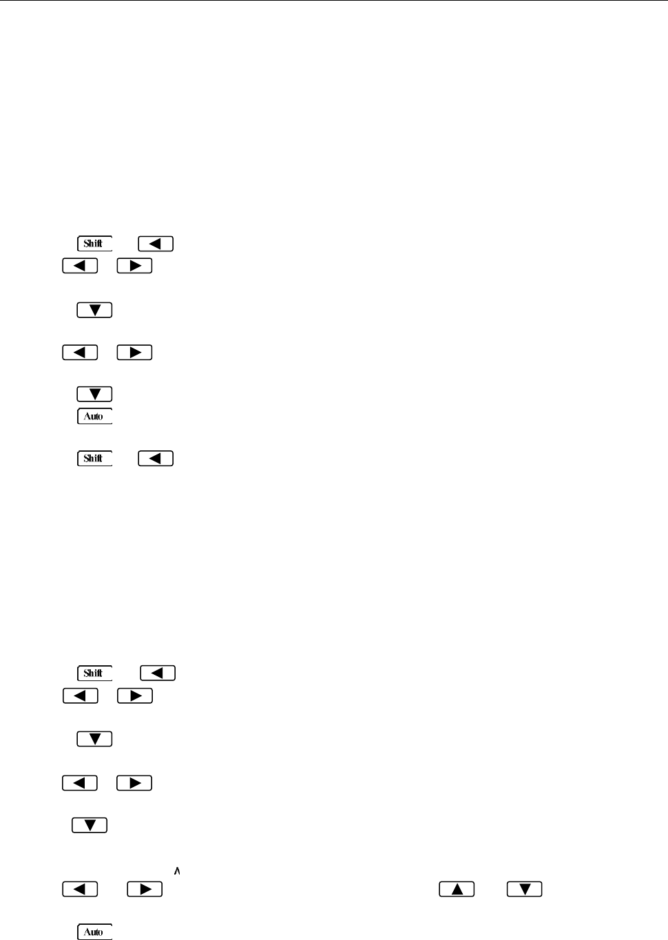
Measurement Options
48
A 0.6kΩ reading becomes 600Ω (HI).
When the reading is within the configured limit range specified by low and high limits, “IN” will be shown
after measured display. If it is higher than the limit range, “HI” will be shown after the measured display.
Similarly, if it is lower than the limit range, “LO” will be shown. You can configure the multimeter to beep
or not when readings are outside of the limit range.
4.4.1 Enabling limits
Use the following procedure to turn on the limit operation:
1. Press → to enter the menu on the menu level, “A: MEAS MENU” will be displayed.
2. Use or key to move across to the MATH MENU on the menu level, “B: MATH MENU”
will be displayed.
3. Press to move down to the command level within the MATH MENU, “1: SET M” will be
displayed.
4. Use or key to move across to the LIMIT TEST command, “6: LIMIT TEST” will be
displayed.
5. Press to move down a level to set LIMIT TEST function to ON.
6. Press (ENTER) to confirm the set of LIMIT TEST function. The message “CHANGE SAVED”
will be displayed to show that the change is now in effect.
7. Press → key to exit from the menu.
8. When the multimeter returns to the measurement display, the HI/IN/LO status will be displayed
along with the reading. If the reading is within the range specified by the high and low limits
(configured in the next section), it will show “IN”. If higher than the range, it will show “HI”. If lower
than the range, it will show “LO”.
4.4.2 Setting Limit Values
Follow the below steps to configure high and low limits for limit operation:
1. Press → to enter the menu on the menu level, “A: MEAS MENU” will be displayed.
2. Use or key to move across to the MATH MENU on the menu level, “B: MATH MENU”
will be displayed.
3. Press to move down to the command level within the MATH MENU, “1: SET M” will be
displayed.
4. Use or key to move across to the HIGH LIMIT command, “7: HIGH LIMIT” will be
displayed.
5. Press to move down a level to input the high limit value. The current high limit value will be
displayed:
HI: +1.00000
6. Use and keys to choose a numerical place and use and keys to increment
or decrement the digits. Enter a high limit value.
7. Press (ENTER) to confirm the value of high limit. The message “CHANGE SAVED” will be
displayed to show that the change is now in effect.
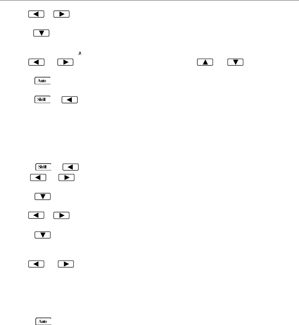
Measurement Options
49
8. Use or key to move across to the LOW LIMIT command, “8: LOW LIMIT” will be
displayed.
9. Press to move down a level to input the low limit value. The current low limit value will be
displayed:
LO: -1.00000
10. Use and keys to choose a numerical place and use and keys to increment
or decrement the digits. Enter a low limit value.
11. Press (ENTER) to confirm the value of low limit. The message “CHANGE SAVED” will be
displayed to show that the change is now in effect.
12. Press → key to exit from the menu.
4.4.3 Configure Limit Beep
Users can configure the multimeter to make a beep sound upon specified conditions when using limit
operation. Follow the below steps to configure:
1. Press → to enter the menu on the menu level, “A: MEAS MENU” will be displayed.
2. Use or key to move across to the MATH MENU on the menu level, “B: MATH MENU”
will be displayed.
3. Press to move down to the command level within the MATH MENU, “1: SET M” will be
displayed.
4. Use or key to move across to the LIMIT BEEP command, “9: LIMIT BEEP” will be
displayed.
5. Press to move down a level to select the condition in which the meter should make a beep
sound when using limit operation. The display should show “ALARM:” with the current selection
blinking.
6. Use and keys to choose between one of the following:
NEVER: Never beep regardless of the limit status (HI, LO, IN).
HI: Beep only when the reading is HI (Reading is above the high limit).
IN: Beep only when the reading is within the range specified by high and low limits.
LO: Beep only when the reading is LO (Reading is below the low limit).
OUT: Beep only when the reading is HI or LO.
7. Press (ENTER) to confirm the value of high limit. The message “CHANGE SAVED” will be
displayed to show that the change is now in effect.
4.5 System Operations
There are some system settings that can be configured on the 5492B multimeter, which include beeper
control, saving and restoring instrument settings, front panel display control, key sound control, self-test,
and calibration. The following sections will describe in details each of these settings.
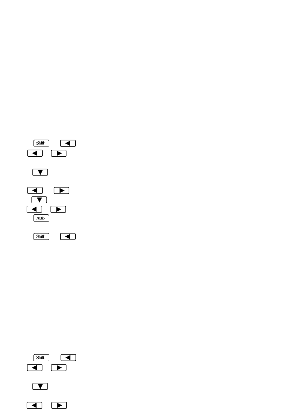
Measurement Options
50
4.5.1 Beeper Control
Under default settings, the multimeter will emit a beep tone whenever certain conditions are met. This
beep can be disabled by the user.
- When you disable the beeper, the multimeter will not emit a tone when:
1. A limit is exceeded in a limit test
- Disabling the beeper has no effect on the tone generated when:
1. An internal error is generated.
2. The continuity threshold is exceeded.
3. A front panel key is pressed (This is controlled by KEY SOUND CONTROL setting).
- The beeper state is stored in non-volatile memory and does not change when power has been off or
after a reset.
Use the following steps to change the beeper’s state:
1. Press → to enter the menu on the menu level, “A: MEAS MENU” will be displayed.
2. Use or key to move across to the SYS MENU on the menu level, “D: SYS MENU” will
be displayed.
3. Press to move down to the command level within the SYS MENU, “1: RDGS STORE” will be
displayed.
4. Use or key to move across to the BEEP command, “4: BEEP” will be displayed.
5. Press to move down a level to set the beeper control.
6. Use or key to select ON or OFF.
7. Press (ENTER) to confirm the beeper control. The message “CHANGE SAVED” will be
displayed to show that the change is now in effect.
8. Press → key to exit from the menu.
4.5.2 Save Settings
The 5492B allows user to save up to 10 instrument settings. These settings are saved as files in
non-volatile memory (10 files: FILE-0 – FILE-9). Files will not be lost when the instrument is powered
off. These settings can be restored at any time after power on. The settings that can be stored in
each file are the same settings listed under the default settings. Refer to section “2.6.4 Power-on
Defaults” for details.
To save settings, first setup the instrument with the settings you want to save. Then, follow the steps
below:
1. Press → to enter the menu on the menu level, “A: MEAS MENU” will be displayed.
2. Use or key to move across to the SYS MENU on the menu level, “D: SYS MENU” will
be displayed.
3. Press to move down to the command level within the SYS MENU, “1: RDGS STORE” will be
displayed.
4. Use or key to move across to the SAVE CNFG command, “5: SAVE CNFG” will be
displayed.
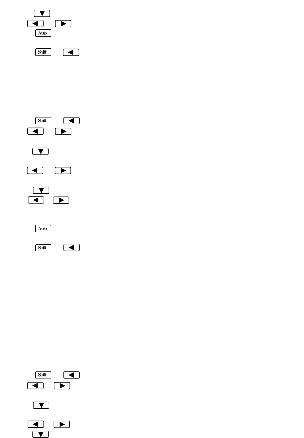
Measurement Options
51
5. Press to move down a level to select a file to save.
6. Use or key to select a file from FILE-0 to FILE-9.
7. Press (ENTER) to save the present setting to the selected file. The message “FILE SAVING”
will display when saving is in progress. Once completed, “SAVE SUCCEED” will be displayed.
8. Press → key to exit from the menu.
4.5.3 Restore Settings
To recall previously saved settings (stored in FILE-0 to FILE-9), or to restore factory default settings,
follow the below steps:
1. Press → to enter the menu on the menu level, “A: MEAS MENU” will be displayed.
2. Use or key to move across to the SYS MENU on the menu level, “D: SYS MENU” will
be displayed.
3. Press to move down to the command level within the SYS MENU, “1: RDGS STORE” will be
displayed.
4. Use or key to move across to the LOAD CNFG command, “6: LOAD CNFG” will be
displayed.
5. Press to move down a level to select a file to restore.
6. Use or key to select “FACT” to restore factory default settings. To restore user saved
settings, select one of the “FILE-#” locations that contain the settings you want to restore (FILE-0 to
FILE-9).
7. Press (ENTER) to restore the selected setting. The message “FILE LOADING” and “LOAD
SUCCEED” will be displayed.
8. Press → key to exit from the menu.
4.5.4 Display Control
To speed up measurement rate for remote control, the 5492B allows the user to turn off the front panel
display.
When the front panel display is turned off, readings are not sent to the display. Some annunciators will
still stay lid. Front panel operation is unaffected by turning off the display.
The display will be enabled again after a power on/off or after a remote interface reset.
To control the display settings, follow the below steps:
1. Press → to enter the menu on the menu level, “A: MEAS MENU” will be displayed.
2. Use or key to move across to the SYS MENU on the menu level, “D: SYS MENU” will
be displayed.
3. Press to move down to the command level within the SYS MENU, “1: RDGS STORE” will be
displayed.
4. Use or key to move across to the DISPLAY command, “7: DISPLAY” will be displayed.
5. Press to move down a level to set the display control.
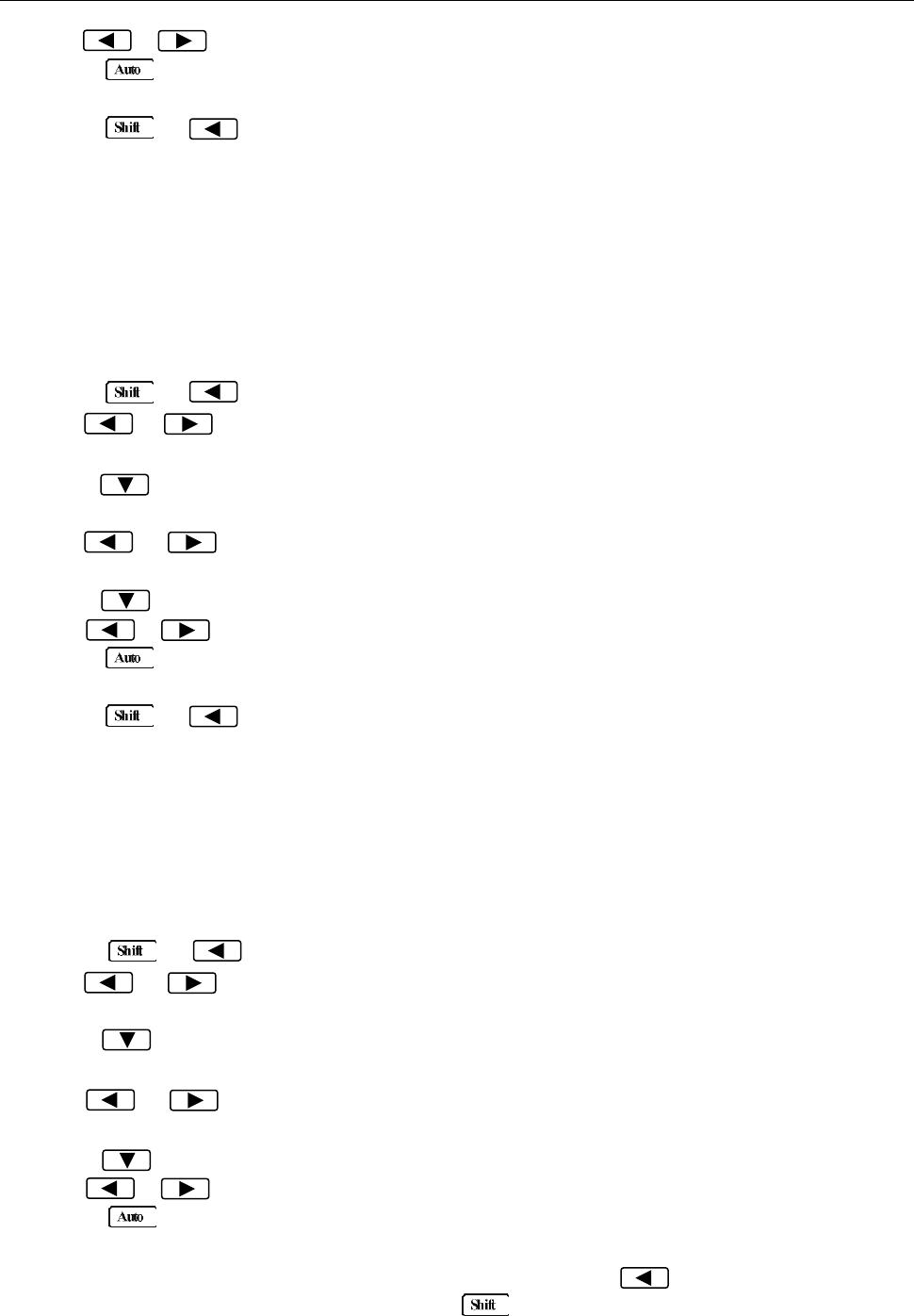
Measurement Options
52
6. Use or key to select ON or OFF for the front panel display.
7. Press (ENTER) to confirm the selection. The message “CHANGE SAVED” will be displayed
to show that the change is now in effect.
8. Press → key to exit from the menu.
4.5.5 Key Sound
The multimeter by default is shipped with beep sound enabled when keys are pressed. This can be set
to ON or OFF by the user.
Follow the steps below to set the key sound settings:
1. Press → to enter the menu on the menu level, “A: MEAS MENU” will be displayed.
2. Use or key to move across to the SYS MENU on the menu level, “D: SYS MENU” will
be displayed.
3. Press to move down to the command level within the SYS MENU, “1: RDGS STORE” will be
displayed.
4. Use or key to move across to the KEY SOUND command, “8: KEY SOUND” will be
displayed.
5. Press to move down a level to enable or disable the key sound.
6. Use or key to turn ON or turn OFF the key sound.
7. Press (ENTER) to confirm the selection. The message “CHANGE SAVED” will be displayed
to show that the change is now in effect.
8. Press → key to exit from the menu.
4.5.6 Self-test
The multimeter has a built-in self-test routine that is processed during an initial power up of the
instrument. Additionally, two other self-test routines can be run from the front panel. To do this, follow
the below steps:
1. Press → to enter the menu on the menu level, “A: MEAS MENU” will be displayed.
2. Use or key to move across to the SYS MENU on the menu level, “D: SYS MENU” will
be displayed.
3. Press to move down to the command level within the SYS MENU, “1: RDGS STORE” will be
displayed.
4. Use or key to move across to the KEY SOUND command, “9: TEST” will be
displayed.
5. Press to move down a level to select the self-test to run.
6. Use or key to select “KEY” (tests the keys) or “BUILT-IN” self-test.
7. Press (ENTER) to confirm the selection.
If “KEY” is selected, it will initially display a message “NO KEY PRESS”. At this point, pressing
any keys will display the key’s function. For example, pressing will display “LEFT PRESS”
message. To exit the key self-test. Press button. After it displays “SHIFT PRESS”

Measurement Options
53
message, it will return to the parameter level for selecting self-test.
If “BUILT-IN” is selected, the unit will run an internal self-test. This will take approximately 10-15
seconds. After completion, the message “TEST PASS” will display if no errors occur during the
self-test.
8. Press → key to exit from the menu.
4.5.7 Calibration
B&K Precision recommends a calibration period of once a year.
Note: To prevent corruption of the calibration data stored in non-volatile memory of the
instrument, only authorized service center or qualified individuals may proceed with
calibrating the instrument.
Please contact B&K Precision for information about instrument calibration.

Remote Operation
54
Chapter 5 Remote Operation
This chapter is outlined as follows:
5.1 Selecting an Interface
5.2 USB & RS-232 Interface Operation
5.3 GPIB Interface operation
5.4 Data Format
The 5492B supports remote control over the USB (virtual com), RS-232, and GPIB interface located in
the rear panel. You can use only one interface at a time. Standard Commands for Programmable
Instruments (SCPI) is supported by these interfaces (unless otherwise noted), however they use
different hardware configurations and communication protocols.
5.1 Selecting an Interface
The 5492B supports the following interfaces for remote communication:
USB (virtual COM) device interface
RS-232 interface
GPIB bus interface (optional) (model 5492BGPIB)
You can only use one interface at a time for remote communication. USB & RS232 interfaces are
selected as the default factory setting. You can select the interface from the front panel menu system.
The interface selection is stored in non-volatile memory and does not change from a power on/off or
instrument reset.
5.1.1 USB (Virtual COM) Interface
The USB device interface on this instrument is a USB virtual COM. After installing the appropriate USB
drivers, the instrument will be recognized and assigned to a COM port automatically by the PC as if it’s a
RS-232 serial interface. Aside from installing drivers, the setup and operation is the same as RS-232
serial interface, which is described in details in the following sections.
Installing USB Driver
To install the USB driver, visit www.bkprecision.com and go to the product page to download the driver.
The drivers are managed and updated by a third-party, so check B&K Precision’s website for the latest
version.
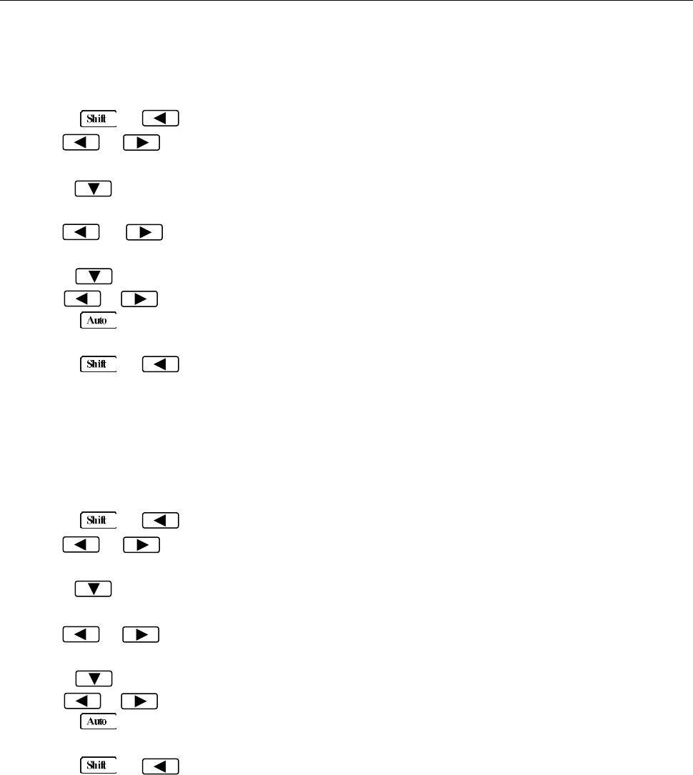
Remote Operation
55
5.1.2 RS-232 Serial Interface
Perform the following steps to select the USB and RS-232 interface for remote communication:
1. Press → to enter the menu on the menu level, “A: MEAS MENU” will be displayed.
2. Use or key to move across to the I/O MENU on the menu level, “E: I/O MENU” will be
displayed.
3. Press to move down to the command level within the I/O MENU, “1: GPIB ADDR” will be
displayed.
4. Use or key to move across to the INTERFACE command, “2: INTERFACE” will be
displayed.
5. Press to move down a level to select an interface.
6. Use or key to select “USB.RS232” option as the interface.
7. Press (ENTER) to confirm the selection. The message “CHANGE SAVED” will be displayed
to show that the change is now in effect.
8. Press → key to exit from the menu.
5.1.3 GPIB Interface (model 5492BGPIB only)
Note: GPIB interface is only available on model 5492BGPIB.
Perform the following steps to select the GPIB interface for remote communication:
1. Press → to enter the menu on the menu level, “A: MEAS MENU” will be displayed.
2. Use or key to move across to the I/O MENU on the menu level, “E: I/O MENU” will be
displayed.
3. Press to move down to the command level within the I/O MENU, “1: GPIB ADDR” will be
displayed.
4. Use or key to move across to the INTERFACE command, “2: INTERFACE” will be
displayed.
5. Press to move down a level to select an interface.
6. Use or key to select “GPIB” option as the interface.
7. Press (ENTER) to confirm the selection. The message “CHANGE SAVED” will be displayed
to show that the change is now in effect.
8. Press → key to exit from the menu.
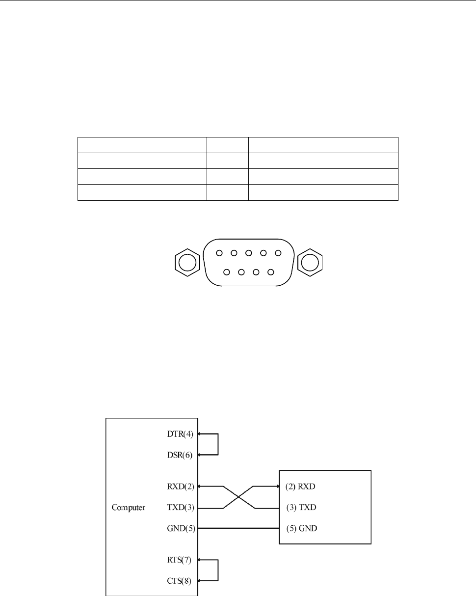
Remote Operation
56
5.2 USB & RS-232 Interface Operation
5.2.1 RS-232 Connection
The RS-232 interface on this instrument uses a 9-pin DB9 connector. The pin outs are defined below in
Table 5-1:
Table 5-1 RS-232 Pin Out
Function
Code
9 Pin Connector Pin Number
Transmitted Data
TXD
3
Received Data
RXD
2
Signal Ground Common
GND
5
Figure 5-1 shows the rear panel connector for the RS232 interface.
Figure 5-1 Rear Panel RS232 Interface
Note: To interface with a serial port on a computer with the RS232 interface, use a NULL
MODEM or CROSS OVER serial DB-9 female to female cable. Do NOT use a straight-through
serial DB-9 cable. To check that you have the correct cable, probe pin 2 on one end and pin 3 on
the other and vice versa to check continuity.
Below is a pin connection diagram between 5492B and a computer (Figure 5-2):
Figure 5-2 RS-232 Connection Sketch
Note: Pin 4 and 6, pin 7 and 8 are shorted respectively at the end of the controller.
Remote Operation
57
5.2.2 Sending and receiving data
The multimeter uses the following settings for USB(virtual com) and RS-232 interface:
Data bits: 8
Stop bit: 1
Parity: None, Even, Odd (selectable from menu)
Flowcontrol: None
Termination character: LF (Line Feed; 0x0A; \n), CR (Carriage Return; 0x0D; \r), or LFCR (Line
Feed and Carriage Return) (Selectable from menu)
5.2.3 Selecting Baud Rate
The multimeter supports the following baudrates: 115200 (115.2K), 57600 (57.6K), 38400 (38.4K),
19200 (19.2K), 9600, 4800, 2400
Note: Factory default baud rate is 9600. Although baudrates 115200 (115.2K) and 57600
(57.6K) are selectable, B&K Precision does not recommend using them for fast repetitive remote
communication as instability and chances of transmission error may increase.
Perform the following steps to select a baud rate:
1. Press → to enter the menu on the menu level, “A: MEAS MENU” will be displayed.
2. Use or key to move across to the I/O MENU on the menu level, “E: I/O MENU” will be
displayed.
3. Press to move down to the command level within the I/O MENU, “1: GPIB ADDR” will be
displayed.
4. Use or key to move across to the BAUD RATE command, “3: BAUD RATE” will be
displayed.
5. Press to move down a level to set the baud rate.
6. Use or key to select a baud rate. Available options are: 115.2K, 57.6K, 38.4K, 19.2K,
9600, 4800, 2400.
7. Press (ENTER) to confirm the selection. The message “CHANGE SAVED” will be displayed
to show that the change is now in effect.
8. Press → key to exit from the menu.
5.2.4 Selecting Parity Mode
The multimeter supports the following parity: NONE, EVEN, ODD.
Perform the following steps to select a Parity mode:
1. Press → to enter the menu on the menu level, “A: MEAS MENU” will be displayed.
2. Use or key to move across to the I/O MENU on the menu level, “E: I/O MENU” will be
displayed.
Remote Operation
58
3. Press to move down to the command level within the I/O MENU, “1: GPIB ADDR” will be
displayed.
4. Use or key to move across to the PARITY command, “4: PARITY” will be displayed.
5. Press to move down a level to set the parity mode.
6. Use or key to select a parity mode. Available options are: NONE, EVEN, ODD.
7. Press (ENTER) to confirm the selection. The message “CHANGE SAVED” will be displayed
to show that the change is now in effect.
8. Press → key to exit from the menu.
5.2.5 Selecting Terminal Character
There are three selectable configurations for terminal characters: LF, CR, LFCR (Asserts both LF and
CR character)
Perform the following steps to select the terminal characters:
1. Press → to enter the menu on the menu level, “A: MEAS MENU” will be displayed.
2. Use or key to move across to the I/O MENU on the menu level, “E: I/O MENU” will be
displayed.
3. Press to move down to the command level within the I/O MENU, “1: GPIB ADDR” will be
displayed.
4. Use or key to move across to the terminal character command, “5: TX TERM” will be
displayed.
5. Press to move down a level to set the terminal character.
6. Use or key to select a terminal character. Available options are: LF, CR, LFCR.
7. Press (ENTER) to confirm the selection. The message “CHANGE SAVED” will be displayed
to show that the change is now in effect.
8. Press → key to exit from the menu.
5.2.6 Selecting Echoing
The instrument allows you to enable or disable echoing. Echoing allows the instrument to respond or
echo back the command string that was sent to the instrument. For example, sending the command
string “*IDN?” will return both “*IDN?” and the query string “5492B Digital Multimeter, Version#, serial#”.
This can be used as a software handshake to verify that the instrument has received the command string
correctly.
Note: This function is for USB (virtual com) and RS-232 interface only.
Perform the following steps to enable or disable echoing.
1. Press → to enter the menu on the menu level, “A: MEAS MENU” will be displayed.
2. Use or key to move across to the I/O MENU on the menu level, “E: I/O MENU” will be
displayed.
Remote Operation
59
3. Press to move down to the command level within the I/O MENU, “1: GPIB ADDR” will be
displayed.
4. Use or key to move across the menu to display “6: RETURN”.
5. Press to move down a level to set the return on or off.
6. Use or key to select ON or OFF to enable or disable echoing respectively.
7. Press (ENTER) to confirm the selection. The message “CHANGE SAVED” will be displayed
to show that the change is now in effect.
8. Press → key to exit from the menu.
5.2.7 Software Protocol
Since the hardware handshaking lines CTS and RTS are not used by the 5492B, the multimeter can be
setup to use the character return (echoing) function as a software handshake to decrease data losses
and errors during communication. Please refer to the content below before remote programming.
1. For remote commands syntax and format, refer to the next chapter for details.
2. The controller (interfacing software or application) transmits the command using ASCII code with
<LF>, <CR> or <LF><CR> as the termination character. The multimeter executes the command
after the termination character is received.
3. The character received by the multimeter will be sent back to the controller again. The controller will
not send the next character until the last returned character is received correctly from the multimeter.
If the controller fails to receive the character sent back by the multimeter, it could be any of the
reasons listed below:
- The serial interface is not connected correctly.
- Check if the RS232 function is enabled. Check that the same baud rate is configured on both
the instrument and the controller.
- When the multimeter is busy with executing a bus command, it will not accept any character
from the serial interface at the same time. So the character sent by controller will be ignored. In
order to make sure the whole command is sent and received correctly, the character without a
return character (if echoing is enabled) should be sent again by the controller.
4. The multimeter only sends information under the following two conditions. The first is when a
character is received normally; the multimeter will send the character back as a response when
return function (echoing) is ON. The second is when a query command is received; the multimeter
will send the query response information.
5. A query response is sent out in ASCII code and includes terminal character.
6. For some commands that will take a long time to execute, for example reset command, the
controller should keep waiting to avoid the next command from being lost when the multimeter
executes it.
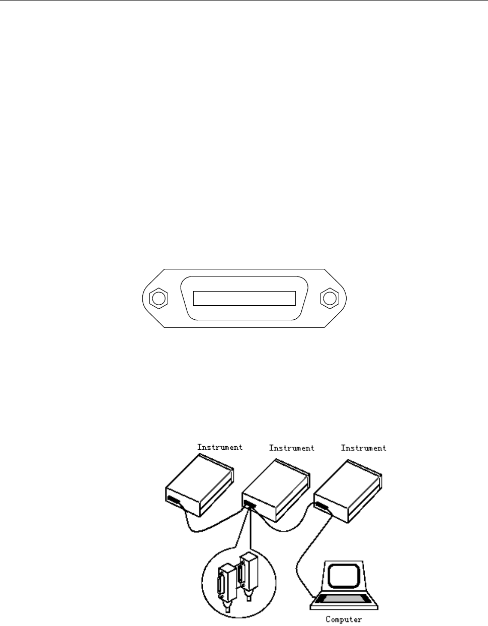
Remote Operation
60
5.3 GPIB Interface operation (model 5492BGPIB only)
5.3.1 GPIB Connection
When configuring a GPIB system, the following restrictions must be adhered to.
The total length of cable in one bus system must be less than or equal to two meters times the
number of devices connected on the bus (the GPIB controller counts as one device) and the
total length of cable must not exceed 20 meters.
A maximum of 15 devices can be connected on one bus system.
There are no restrictions on how the cables are connected together. However, it is
recommended that no more than four piggyback connectors be stacked together on any one
device. The resulting structure could exert enough force on the connector mounting to damage
it.
Figure 5-3 shows the GPIB interface on the rear panel of the 5492BGPIB.
Figure 5-3 Rear Panel GPIB Interface
To allow many parallel connections to one instrument, stack the connector. Two screws are located on
each connector to ensure that connections remain secure. Figure 5-4 shows a typical GPIB system
interconnection.
Figure 5-4 Typical GPIB System Interconnection
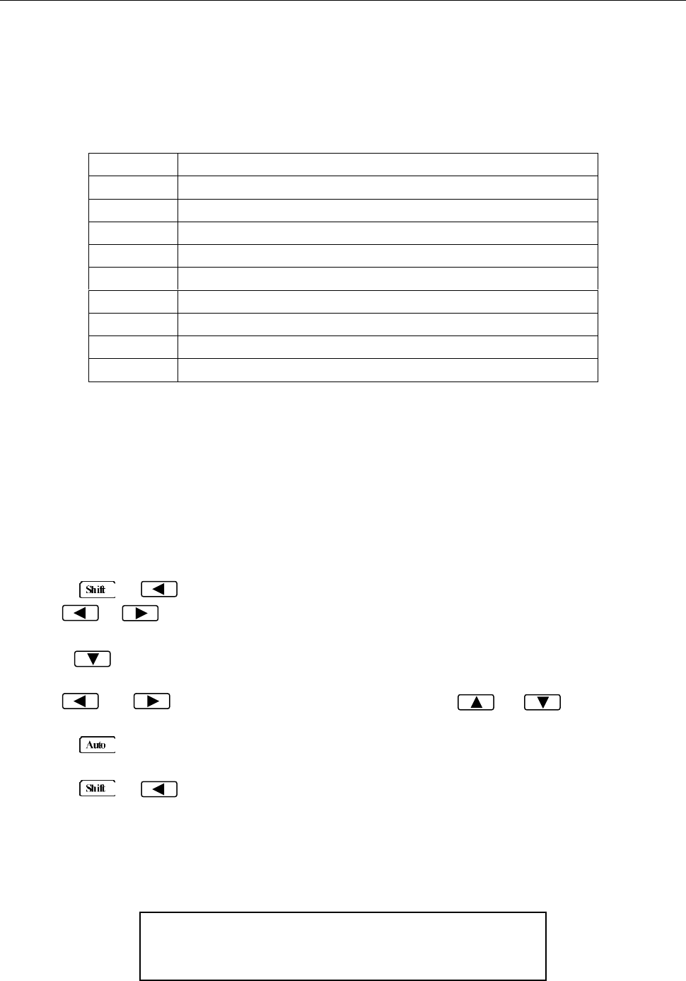
Remote Operation
61
5.3.2 GPIB Interface Capability
Table 5-3 lists the multimeter’s GPIB capabilities and functions. These functions provide the mean for an
instrument to receive, process, and transmit commands, data, and status over the GPIB bus.
Table 5-3 GPIB interface Capability
Code
Function
SH1
Complete Source Handshake capability
AH1
Complete Acceptor Handshake capability
T5
Basic Talker; Talk-Only; Unaddressed if MLA; no serial poll.
L4
Basic Listener; Unaddressed if MTA; no Listen Only.
RL1
Remote/Local capability
DC1
Device Clear capability
DT1
Device Trigger capability
C0
No controller capability
E1
Drivers are open-collector
5.3.3 GPIB Addressing
The factory default setting for the GPIB address is 8. You can set the address to a value of 0 to 31 and
the address is saved in the non-volatile memory. Do not assign the same address to another device or
a controller that are on the same GPIB bus system.
Follow the below steps to change the GPIB address:
1. Press → to enter the menu on the menu level, “A: MEAS MENU” will be displayed.
2. Use or key to move across the I/O MENU on the menu level, “E: I/O MENU” will be
displayed.
3. Press to move down to the command level within the I/O MENU, “1: GPIB ADDR” will be
displayed.
4. Use and keys to choose a numerical place and use and keys to increment
or decrement the digits. Enter a value for the GPIB address (0 to 31).
5. Press (ENTER) to confirm the address. The message “CHANGE SAVED” will be displayed to
show that the change is now in effect.
6. Press → key to exit from the menu.
5.4 Data Format
5492BGPIB outputs the measurement results using the ASCII character string format via the GPIB bus.
The data format is described in the following Figure 5-5.
SD.DDDDDDESDDD<NL>
S: +/- E: exponent sign (“+”is omitted)
D: number 0 to 9 <NL>: New Line; Termination character
Figure 5-5 Data Format
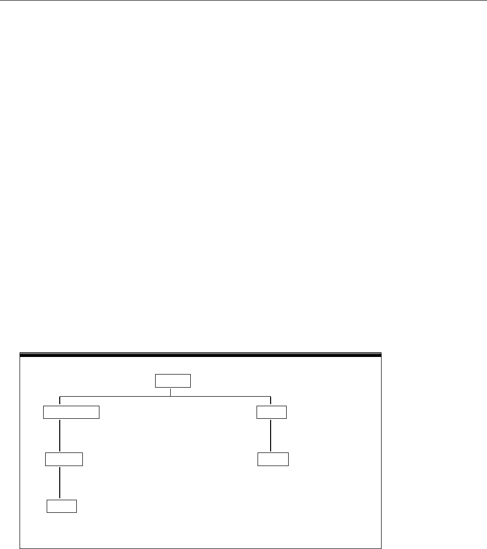
SCPI Command Reference
62
Chapter 6 SCPI Command Reference
This chapter is outlined as follows:
6.1 Command Structure
6.2 Command Syntax
6.3 Command Reference
6.1 Command Structure
The remote commands are divided into two types: Common commands and SCPI commands. The
common commands are defined in IEEE std. 488.2-1987, and these commands are common for all
devices. Not all commands are supported by the 5492B, and some commands are not supported by the
GPIB interface for the 5492BGPIB. Please look through the command syntax thoroughly before
programming. The SCPI commands are used to control most of the 5492B functions. They can be
represented as a tree structured with three levels deep. (The highest level commands are called the
subsystem commands in this manual.) The lower level commands are part of subsystem commands and
a colon (:) is used to separate the higher level commands and the lower level commands. See Figure 6-1
as an example.
SENSe
RESistance HOLD
RANGe STATe
SENS:RES:RANG 1k SENS:HOLD:STAT ON
AUTO
SENS:RES:RANG:AUTO ON
Figure 6-1 Command Tree Example

SCPI Command Reference
63
6.2 Command Syntax
6.2.1 Commands and command parameters
Common commands and SCPI commands may or may not use a parameter. The following are some
examples:
*RST No parameter used
:FORMat <name> Parameter<name> required
:IMMediate No parameter used
For commands that use a parameter, include a space in between the command and the parameter.
- Brackets [ ]: Some command words are enclosed in brackets. These brackets are used to denote
an optional command word that does not need to be included in the program message. For
example:
:RANGe[:UPPer] <n>
These brackets indicate that :UPPer is optional and does not have to be used. Thus, the above
command can be sent in one of the two ways below:
:RANGe <n>
or :RANGe:UPPer <n>
NOTICE: When using optional command words in your program, do not include the
brackets.
- Angel brackets <>: Angle brackets are used to denote a parameter type. Do not include the
brackets in the program message. For example:
:HOLD:STATe <b>
The <b> indicates that a Boolean-type parameter is required. Thus, to enable the HOLD feature,
you must send the command with ON or 1 parameter as below:
:HOLD:STATe ON
or :HOLD:STATe 1
- Parameter types: The following are some of the more common parameter types:
<b> Boolean: Used to enable or disable an instrument operation. “0” or “OFF” disables the
operation and “1” or “ON” enables the operation. Example:
:CURRent:AC:RANGe:AUTO ON Enable autoranging
<name> Name parameter: Select a parameter name from a listed group. Example:

SCPI Command Reference
64
<name> = MOVing
REPeat
:RESistance:AVERage:TCONtrol MOVing
<NRf> Numeric Representation format: This parameter is a number that can be expressed as
an integer (e.g., 6), a real number (e.g., 25.3) or an exponent (e.g., 5.6E2). Example:
:MMFactor 5
<n> Numeric value: A numeric value parameter can consist of a NRf number or one of the
following name parameters: DEFault, MINimum, MAXimum. When DEFault
parameter is used, the instrument is programmed to the *RST default value. When
the MINimum parameter is used, the instrument is programmed to the lowest
allowable value. When the MAXimum parameter is used, the instrument is
programmed to the largest allowable value. Examples:
[:SENSe[1]]:CURRent[:DC]:NPLCycles 1
[:SENSe[1]]:CURRent[:DC]:NPLCycles DEFault
[:SENSe[1]]:CURRent[:DC]:NPLCycles MINimum
[:SENSe[1]]:CURRent[:DC]:NPLCycles MAXimum
6.2.2 Short-form Rules
Use the following rules to determine the short-form version of any SCPI command:
- If the length of the command word is four letters or less, no short form version exists. Example:
:AUTO = :AUTO
- These rules apply to command words that exceed four letters, with some exceptions.
- If the fourth letter of the command word is a vowel, delete it and all the letters after it. Example:
:immediate = :imm
- Rule exception – The short form version of the following command uses only the first two letters of
the word.
:TCouple = :tc
- If the fourth letter of the command word is a consonant, retain it but drop all the letters after it.
Example:
:FORMat = :FORM
- If the command contains a question mark (?; query) or a non-optional number included in the
command word, you must include it in the short-form version. Example:
:delay? = :del?
- Command words or characters that are enclosed in brackets ([ ]) are optional and need not be
included in the program message.

SCPI Command Reference
65
6.2.3 Basic Rules of Command Structure
- Commands are not case sensitive.
For example:
FUNC:VOLT:DC = func:volt:dc = Func:Volt:Dc
- Spaces (︺ is used to indicate a space) must not be placed before and/or after the colon (:).
For example:
(wrong) FUNC
︺
:
︺
VOLT:DC
(right) FUNC:VOLT:DC
- The command can be completely spelled out or in abbreviated type. (In the following description,
short form will be printed in upper case.)
For example:
FUNCTION: VOLTAGE:DC = FUNC: VOLT:DC
- The command header should be followed by a question mark (?) to generate a query for that
command.
For example:
FUNC?
6.2.4 Multiple Command Rules
The semicolon (;) can be used as a separator to execute multiple commands on a single line. The
multiple command rules are as follows.
- Commands at the same level and in the same subsystem command group can be separated by a
semicolon (;) on a multiple command line.
For example:
CALCulate3:LIMit[1]:STATe <b>;STATe?
- To restart commands from the highest level, a semicolon (;) must be used as the separator, and
then a leading colon (:), which shows that the restarted command is a command at the top of the
command tree.
For example:
:CALCulate[1]:FORMat?;:CALCulate[1]:KMATh:MMFactor <NRf>
- The common commands can restart only after a semicolon on a multiple command line.
For example,
CALCulate3:LIMit[1]:STATe <b>;*IDN?
6.2.5 Command Path Rules
- Each new program message must begin with the root command, unless it is optional (e.g.,
[:SENSe]). If the root is optional, simply treat a command word on the next level as the root.
- The colon at the beginning of a program message is optional and need not be used. Example:
:DISPlay:ENABle <b> = DISPlay:ENABle <b>
- When the path pointer detects a colon(;), it moves down to the next command level.

SCPI Command Reference
66
- When the path pointer detects a colon (:) after a semicolon (;), it resets back to the root level.
- The path pointer can only move down. It cannot be moved up a level. Executing a command at a
higher level requires that you start over at the root command.
6.3 Command Reference
The following are the subsystem commands:
DISPlay
CALCulate
SENSe
SYStem
UNIT
TRIGger
The supported common commands are:
*RST
*TRG
*IDN?
6.3.1 Measurement Commands
The measurement commands described in this section are used to acquire readings. These commands
are summarized in Table 6-1 below.
Table 6-1 Signal Oriented Measurement Command Summary
Command
Function Description
MEASure:<function>?
:CONFigure:<function>
:FETCh?
:READ?
Perform an :ABORt, :CONFigure:<function>, and :READ?
Configure instrument to the selected measurement function.
Request the latest reading.
Perform an :ABORt, :INITiate, and a :FETCh?

SCPI Command Reference
67
MEASure command
Command syntax:
:MEASure:<function>?
Command parameter :
<function> = VOLTage:DC DC voltage
VOLTage:AC AC voltage
CURRent:DC DC current
CURRent:AC AC current
RESistance 2-wire resistor
FRESistance 4-wire resistor
FREQuency Frequency
PERiod Period
DIODe Diode testing
CONTinuity Continuity test
Return String:
Returns a measured reading.
Description:
This command combines all of the other signal oriented measurement commands to perform a “one
time” measurement and acquire the reading.
When this command is sent, the following commands execute in order:
:ABORt
:CONFigure:<function>
:READ?
When :ABORt is executed, if continuous initiation is disabled, the instrument goes into the idle
state. If continuous initiation is enabled, the operation re-starts at the beginning of the Trigger
Model.
When :CONFigure is executed, the instrument goes the selected measurement mode.
When :READ? is executed, another :ABORt is performed, then an :INITiate, and finally a FETCh? to
acquire the reading.

SCPI Command Reference
68
CONFigure Command
Command syntax:
:CONFigure:<function>
Command parameter :
<function> = VOLTage:DC DC voltage
VOLTage:AC AC voltage
CURRent:DC DC current
CURRent:AC AC current
RESistance 2-wire resistor
FRESistance 4-wire resistor
FREQuency Frequency
PERiod Period
DIODe Diode testing
CONTinuity Continuity test
Query:
:CONFigure? Query the selected function.
Return String Example:
volt:dc
Description:
This command configures the instrument for subsequent measurements on the specified function. It
places the instrument in the selected measurement mode. You then use the :READ? command to
trigger a measurement and acquire a reading.
When this command is sent, the multimeter will be configured as follows:
- The function specified by this command is selected.
- All controls related to the selected function are defaulted to the *RST values.
- Continuous initiation is disabled.
- The control source of the Trigger Model is set to Immediate.
- The delay of the Trigger Model is set to zero.
- All math calculations are disabled.
- Buffer operation is disabled. A storage operation currently in process will be aborted.
- Autozero is set to the *RST default value.
This command is automatically asserted when the :MEASure? Command is sent.

SCPI Command Reference
69
FETCh Command
Command syntax:
:FETCh?
Description:
This query command is used to obtain the lastest post-processed reading. This command does
not affect the configuration of the instrument.
This command does not trigger a measurement. The command simply requests the last available
reading. It will continue to return the same reading until there is a new reading.
This command will be automatically asserted when :READ? or :MEASure? command is sent.
Continuous initiation must be enabled or an error will occur when sending this command.
READ Command
Command syntax:
:READ?
Description:
When this command is sent, the following commands execute in order:
:ABORt
:INITiate
:FETCh?
When :ABORt is executed, if continuous initiation is disabled, the instrument goes into the idle state.
If continuous initiation is enabled, the operation re-starts at the beginning of the Trigger Model.
If the instrument is in the idle state, :INITiate takes the instrument out of the idle state. If continuous
initiation is enabled (:INITiate:CONTinuous ON), then the :INITiate command generates an error
and ignores the command.
See the :FETCh? command for more details. Note that an “Init ignored” error will not cancel the
execution of the :FETCh? command.
NOTE: You cannot use the :READ? command if there are readings stored in the buffer
(error -225, out of memory). Clear the buffer before using :READ?

SCPI Command Reference
70
6.3.2 DISPlay subsystem
The DISPlay subsystem commands are mainly used to control the display of the multimeter and are
summarized in Table 6-2.
Table 6-2 DISPlay Subsystem Commands Summary
Command
Function Description
:DISPlay
:ENABle <b>
:ENABle?
Enable or disable front panel display
Query state of the display
:ENABle <b>
Command syntax:
:DISPlay:ENABle <b>
Command Parameter:
<b> = 0 or OFF Disable front panel display
1 or ON Enable front panel display
Query:
:ENABle? Query state of the display
Return String:
1 or 0
Description:
This command is used to enable or disable front panel display circuitry. When disabled, the
instrument operates at a higher speed. While disabled, the display will be frozen. All front panel
controls except LOCAL are disabled. Normal display operation can be resumed by using :ENABle
command or pressing LOCAL key to enable the display.
6.3.3 CALCulate Subsystem
The commands in this subsystem are used to configure and control the calculate subsystems and are
summarized in Table 6-3.
Table 6-3 CALCulate Command Summary
Command
Function Description
Default
Parameter
:CALCulate[1]
:FORMat <name>
:FORMat?
:KMATh
:MMFactor <NRf>
:MMFactor?
Subsystem to control CALC1 (MX+B and % MATH)
Select math format (NONE,MXB,PERCent)
Query math format.
Path to configure math calculations:
Set “m” factor for mx+b (-100e6 to 100e6)
Query “m” factor
NONE
1

SCPI Command Reference
71
:MBFactor <NRf>
:MBFactor?
:PERCent <NRf>
:ACQuire
:PERCent?
:STATe <b>
:STATe?
:DATA?
:CALCulate2
:TRACe
:CLEar
:POINTS <NRf>
:POINTS?
:DATA?
:FORMat <name>
:FORMat?
:STATe <b>
:STATe?
:DATA?
:CALCulate3
:LIMit[1]
:UPPer <n>
:UPPer?
:LOWer <n>
:LOWer?
:STATe <b>
:STATe?
:FAIL?
Set “b” factor for mx+b (-100e6 to 100e6)
Query “b” factor
Set target value for PERCent calculation(-100e6 ~100e6)
Use input signal as target value.
Query percent
Enable or disable KMATh calculation
Query state of KMATh calculation
Read result of KMATh calculation
Subsystem to control CALC2 (Buffer operation)
Clear readings in the buffer.
Specify the size of buffer (2 to 512)
Query buffer size.
Read all readings in the buffer. (GPIB not supported)
Select type of statistical calculation for readback
Query the type of statistical calculation for readback
Enable or disable store reading
Query state of store reading function
Read statistical calculated result
Subsystem to control CALC3 (Limit test operation):
Set upper limit (-100e6 to 100e6).
Query upper limit.
Set lower limit (-100e6 to 100e6).
Query lower limit
Enable or disable limit test
Query state of limit test
Query test result (1=pass, 0=fail)
0
1
NONE
1
-1
OFF

SCPI Command Reference
72
:CALCulate[1] Subsystem
Use this subsystem for commands to configure and control MXB and percent math calculations.
:FORMat <name>
Command syntax:
:CALCulate[1]:FORMat <name>
Command Parameter:
<name> = NONE No calculations
MXB MX+B math calculation
PERCent Percent math calculation
Query:
:FORMat? Query programmed math format
Return String:
NONE, MXB, or PERC
Description:
This command is used to specify the format for the CALC1 math calculations. With NONE
selected, no CALC1 calculation is performed. With MXB or PERCent selected and enabled, the
result of the calculation is displayed. The calculated reading is refreshed every time the instrument
takes a reading.
:KMATh Commands
:MMFactor <NRf>
Command syntax:
:CALCulate[1]:KMATh:MMFactor <NRf>
Command Parameter:
<NRf> = -100e6 to 100e6 Specify “m” factor.
Query:
:MMFactor? Query “m” factor.
Return String:
The value of m in <NRf> format
Description:
This command is used to define the “m” factor for the mx+b calculation.
:MBFactor <NRf>
Command syntax:
:CALCulate[1]:KMATh:MBFactor <NRf>
Command Parameter:
<NRf> = -100e6 to 100e6 Specify “b” factor.

SCPI Command Reference
73
Query:
:MBFactor? Query “b” factor
Return String:
The value of b in <NRf> format
Description:
This command is used to define the “b” factor for the mx+b calculation.
:PERCent <NRf>
Command syntax:
:CALCulate[1]:KMATh:PERCent <NRf>
Command Parameter:
<NRf> = -1e6 to1e6 Specify target value.
Query:
:PERCent? Query percent target value
Description:
This command is used to specify the target value for the percent calculation.
:ACQuire
Command syntax:
: CALCulate[1]:KMATh:PERCent:ACQuire
Description:
This action command is used to acquire the current reading and use it as the target value for the
PERCent calculation.
:STATe <b>
Command syntax:
:CALCulate[1]:STATe <b>
Command Parameter:
<b> = 0 or OFF Disable CALC1 calculation.
1 or ON Enable CALC1 calculation.
Query:
:STATe? Query state (ON or OFF) of CALC1.
Return String:
1 or 0

SCPI Command Reference
74
Description:
This command is used to enable or disable the CALC1 calculation. When enabled, each instrument
reading will reflect the selected calculation.
:DATA?
Command syntax:
:CALCulate[1]:DATA?
Return String:
Math calculated measurement in <NRf> format
Description:
This query command is used to read the result of the CALC1 calculation. If CALC1 is disabled or
NONE is selected, the measured reading without the math calculations will be returned.
:CALCulate2 Subsystem
Use this subsystem for commands to configure and control buffer operations.
:TRACe Command
:CLEar
Command syntax:
:CALCulate2:TRACe:CLEar
Description:
This action command is used to clear the readings in the buffer. If the buffer is not cleared, a
subsequent store will overwrite the previous readings. If the subsequent store is aborted before the
buffer becomes full, you could end up with some readings that were previously stored in the buffer.
Note: For USB(virtual com) and RS-232 interface, this command must be used before a
subsequent store can process. You will know that the display will not have “*” lid up until the
buffer is cleared, even if store reading function is enabled with “:CALC2:STAT 1” command.
:POINTS <NRf>
Command syntax:
:CALCulate2:TRACe:POINTS <NRf>
Command Parameter:
<NRf> = 2 to 512 Specify buffer size.
Query:
:POINTS? Query buffer size.
Description:
This command is used to specify the buffer size, which in turn sets the number of readings to store.

SCPI Command Reference
75
:DATA?
Command syntax:
:CALCulate2:TRACe:DATA?
Return String Format:
If no readings are in buffer: Empty
If 5 readings are in buffer:
<reading><sp><unit>:<LF>
<reading><sp><unit>:<LF>
<reading><sp><unit>:<LF>
<reading><sp><unit>:<LF>
<reading><sp><unit>:<LF>
Note: Using GPIB interface, the Return String Format will be different than above in that
<LF> character will not follow after every reading. For example, for 2 readings, the
format will be:
<reading><sp><unit>:<reading><sp><unit>:
Where:
<reading> - This is the stored reading and consists of 8 characters, which includes decimal.
If the reading does not take up 8 characters, the unused characters become spaces.
For example: If the stored reading is 11.0016, the return string is: _ 11.0016
If the stored reading is 0.326, the return string is: _ _ _0.326
(where _ is a space)
<sp> - This is a space character.
<unit> - This is the unit notation that corresponds to the <reading>.
It can be m (10-3), u(10-6), or n(10-9).
If the <reading> does not require a unit notation, this becomes a <sp>.
For example: 1.234 VDC does not require a unit notation.
<LF> - Linefeed character (0x0A, \n)
Description:
When this command is sent, all the readings stored in the buffer are sent to the computer. If there
are no readings in the buffer, it will return with the string “Empty”.

SCPI Command Reference
76
:FORMat <name>
Command syntax:
:CALCulate2:FORMat <name>
Command Parameter:
<name> = NONE No calculation
MAXimum Largest reading in buffer
MINimum Lowest reading in buffer
MEAN Mean (average) value of readings in buffer
SEDViation Standard deviation of readings in buffer
Query:
:FORMat? Query programmed math format.
Return String:
NONE, MEAN, SEDV, MAX, or MIN
Description:
This command is used to specify which statistical calculations to recall (using “:CALC2:DATA?”
command) from the stored readings in the buffer. If NONE is selected or if the buffer is empty,
using “:CALC2:DATA?” command will return the current measured reading on the display.
:STATe <b>
Command syntax:
:CALCulate2:STATe <b>
Command Parameter:
<b> = 0 or OFF Disable store reading
1 or ON Enable store reading
Query:
:STATe? Query state (ON or OFF) of store reading function
Return String:
1 or 0
Description:
This command is used to enable or disable store reading. It is equivalent to setting “RDGS
STORE” to ON from the front panel menu. When enabled, readings on the display will immediately
begin storing into the buffer if the meter is already in measurement mode.
For USB/RS-232 Interface: To store reading subsequently with this command, the buffer must be
cleared prior to sending this command using the “:CALC2:TRAC:CLE” command.

SCPI Command Reference
77
:DATA?
Command syntax:
:CALCulate2:DATA?
Return String:
<reading><sp>
where
<reading> - This is the stored reading and consists of 8 characters, which includes decimal.
If the reading does not take up 8 characters, the unused characters become spaces.
For example: If the stored reading is 11.0016, the return string is: _ 11.0016
If the stored reading is 0.326, the return string is: _ _ _0.326
(where _ is a space)
<sp> - This is a space character.
Description:
This query command will return a statistical calculation result based on the stored readings inside
the buffer. It can be either the Maximum reading, minimum reading, the average of the stored
readings, or the standard deviation based on the stored readings. The “:CALC2:FORM” command
is used to select which calculation result to return after this query.
:CALCulate3 Subsystem
These commands are used to configure and control the limit test.
:LIMit[1]:UPPer <n> Specify upper limit
:LIMit[1]:LOWer <n> Specify lower limit
Command syntax:
:CALCulate3:LIMit[1]:UPPer <n>
:CALCulate3:LIMit[1]:LOWer <n>
Command Parameter:
<n> = -100e6 to 100e6 Specify limit value
Query:
:UPPer? Query upper limit
:LOWer? Query lower limit
Return String:
<n>
where
<n> - Specified limit value.

SCPI Command Reference
78
Description:
This command is used to specify the upper and lower limit for limit testing. The actual limit depends
on which measurement function is currently selected. For example, a limit value of 1 is 1V for the
voltage measurement functions (DCV or ACV), 1A for the current measurement functions (DCI or
ACI), 1 Ω on the resistance measurement function (2-wire or 4-wire). A limit value is not range
sensitive. For example, a limit of 1 for DCV is 1 V on all measurement ranges.
:STATe <b>
Command syntax:
:CALCulate3:LIMit[1]:STATe <b>
Command Parameter:
<b> = 0 or OFF Disable limit test
1 or ON Enable limit test
Query:
:STATe? Query state (on or off) of limit test
Return String:
1 or 0
Description:
This command is used to enable or disable the limit test function. When enabled, the limit test will be
active.
:FAIL?
Command syntax:
:CALCulate3:LIMit[1]:FAIL?
Description:
This command is used to read the results of the limit test
0 = Limit test failed
1 = Limit test passed
The response message (0 or 1) only tells you if a limit test has passed or failed. In the case of 0
(failed), it does not tell you which limit (upper or lower) has failed.

SCPI Command Reference
79
6.3.4 SENSe subsystem command
This SENSe subsystem is used to configure and control the 5492B measurement functions and are
summarized in Table 6-4 below.
Table 6-4 SENSe Command Summary
Command
Function Description
Default
[:SENSe[1]]
:FUNCtion<name>
:FUNCtion?
:DATA?
Select measurement function: ‘VOLTage:AC’,
‘VOLTage:DC’, ‘RESistance’, ‘FRESistance’,
‘CURRent:AC’, ‘CURRent:DC’, ‘FREQuency’,
‘PERiod’, ‘DIODe’, ‘CONTinuity’.
Query function.
Output the latest reading
VOLT:DC
:CURRent:AC
:NPLCycles <n>
:NPLCycles?
:RANGe
[:UPPer] <n>
[:UPPer]?
:AUTO <b>
:AUTO?
:REFerence <n>
:STATe <b>
:STATe?
:ACQuire
:REFerence?
:AVERage
:TCONtrol <name>
:TCONtrol?
:COUNt <n>
:COUNt?
:STATe <b>
:STATe?
Path to configure AC current
Set A/D integration rate (Line cycle; 0.1 to 10)
Query line cycle integration rate
Path to configure measurement ranges
Select range
Query range
Enable or disable auto range
Query auto range
Specify reference (-10 to 10)
Enable or disable reference
Query state of reference
Use input signal as reference
Query reference value
Path to configure and control the filter
Select filter type(MOVing or REPeat)
Query filter type
Specify filter count (1 to 100)
Query filter count
Enable or disable filter
Query state of digital filter
1
10
ON
0
OFF
5
OFF

SCPI Command Reference
80
Table 6-4 SENSe Command Summary (cont.)
Command
Function Description
Default
:CURRent:DC
:NPLCycles <n>
:NPLCycles?
:RANGe
[:UPPer] <n>
[:UPPer]?
:AUTO <b>
:AUTO?
:REFerence <n>
:STATe <b>
:STATe?
:ACQuire
:REFerence?
:AVERage
:TCONtrol <name>
:TCONtrol?
:COUNt <n>
:COUNt?
:STATe <b>
:STATe?
Path to configure DC current
Set integration rate(line cycles; 0.1 to 10)
Query line cycle integration rate
Path to configure measurement range
Select range (0 to 10)
Query range
Enable or disable auto range
Query auto range
Specify reference (-10 to 10)
Enable or disable reference
Query state of reference
Use input signal as reference
Query reference value
Path to configure and control the filter
Select filter type (MOVing or REPeat)
Query filter type
Specify filter count (1 to 100)
Query filter count
Enable or disable filter
Query state of digital filter
1
10
ON
0
OFF
5
OFF
:VOLTage:AC
:NPLCycles <n>
:NPLCycles?
:RANGe
[:UPPer] <n>
[:UPPer]?
:AUTO <b>
:AUTO?
:REFerence <n>
:STATe <b>
:STATe?
:ACQuire
:REFerence?
:AVERage
:TCONtrol <name>
:TCONtrol?
:COUNt <n>
:COUNt?
:STATe <b>
:STATe?
Path to configure AC voltage
Set integration rate (line cycles; 0.1 to 10)
Query line cycle integration rate
Path to set measurement range
Select range
Query range
Enable or disable auto range
Query auto range
specify reference (-757.5 to 757.5)
Enable or disable reference
Query state of reference
Use input signal as reference
Query reference value
Path to configure and control the filter
Select filter type: MOVing or REPeat
Query filter type
Specify filter count (1 to 100)
Query filter count
Enable or disable filter
Query state of digital filter
1
750
ON
0
OFF
5
OFF

SCPI Command Reference
81
Table 6-4 SENSe Command Summary (cont.)
Command
Function Description
Default
:VOLTage:DC
:NPLCycles <n>
:NPLCycles?
:RANGe
[:UPPer] <n>
[:UPPer]?
:AUTO <b>
:AUTO?
:REFerence <n>
:STATe <b>
:STATe?
:ACQuire
:REFerence?
:AVERage
:TCONtrol <name>
:TCONtrol?
:COUNt <n>
:COUNt?
:STATe <b>
:STATe?
Path to configure DC voltage
Set integration rate (line cycle; 0.1 to 10)
Query line cycle integration rate
Path to configure measurement range
Select range
Query range
Enable or disable auto range
Query auto range
Specify reference (-1010 to 1010)
Enable or disable reference
Query state of reference (0,1)
Use input signal as reference.
Query reference value
Path to configure and control the filter
Select filter type (MOVing, REPeat)
Query filter type
Specify filter count (1 to 100)
Query filter count
Enable or disable filter
Query state of digital filter
1
1000
ON
0
OFF
5
OFF
:RESistance
:NPLCycles <n>
:NPLCycles?
:RANGe
[:UPPer] <n>
[:UPPer]?
:AUTO <b>
:AUTO?
:REFerence <n>
:STATe <b>
:STATe?
:ACQuire
:REFerence?
:AVERage
:TCONtrol <name>
:TCONtrol?
:COUNt <n>
:COUNt?
:STATe <b>
:STATe?
Path to configure 2-wire resistance
Set integration rate (line cycles: 0.1 to 10)
Query line cycle integration rate
Path to configure measurement range
Select range
Query range
Enable or disable auto range
Query auto range
Specify reference (0 to 120e6)
Enable or disable reference
Query state of reference
Use input signal as reference
Query reference value
Path to configure and control filter
Select filter type (MOVing, REPeat)
Query filter type
Specify filter count (1 to 100)
Query filter count
Enable or disable filter
Query state of digital filter
1
100e6
ON
0
OFF
5
OFF

SCPI Command Reference
82
Table 6-4 SENSe Command Summary (cont.)
Command
Function description
Default
:FRESistance
:NPLCycles <n>
:NPLCycles?
:RANGe
[:UPPer] <n〉
[:UPPer]?
:AUTO <b>
:AUTO?
:REFerence <n>
:STATe <b>
:STATe?
:ACQuire
:REFerence?
:AVERage
:TCONtrol <name>
:TCONtrol?
:COUNt <n>
:COUNt?
:STATe <b>
:STATe?
Path to configure 4-wire resistance
Set integration rate (line cycle: 0.1 to 10)
Query line cycle integration rate
Path to configure measurement range
Select range
Query range
Enable or disable auto range
Query auto range
Specify reference (0 to 1201e6)
Enable or disable reference
Query state of reference
Use input signal as reference
Query reference value
Path to configure and control filter
Select filter type (MOVing, REPeat)
Query filter type
Specify filter count (1 to 100)
Query filter count
Enable or disable filter
Query state of digital filter
1
100e6
ON
0
OFF
5
OFF
:FREQuency
:THReshold
:VOLTage
:RANGe <n>
:RANGe?
:REFerence <n>
:STATe <b>
:STATe?
:ACQuire
:REFerence?
Path to configure frequency
Path to select the threshold voltage range:
Select threshold range
Query threshold range
Specify reference (0 to 1.5e7)
Enable or disable reference
Query state of reference
Use input signal as reference
Query reference value
10
0
OFF
:PERiod
:THReshold
:VOLTage
:RANGe <n>
:RANGe?
:REFerence <n>
:STATe <b>
:STATe?
:ACQuire
:REFerence?
Path to configure period
Path to select the threshold voltage range:
Select threshold range
Query threshold range
Specify reference (0 to 1)
Enable or disable reference
Query state of reference
Use input signal as reference
Query reference value
10
0
OFF

SCPI Command Reference
83
Table 6-4 SENSe Command Summary (cont.)
Command
Function description
Default
:DIODe
:CURRent
:RANGe
[:UPPer] <NRf>
[:UPPer]?
Path to configure diode test
Path to select range
Select range
Query range
1e-3
:CONTinuity
:THReshold <NRf>
:THReshold?
Path to configure continuity test
Specify threshold resistance (1 to 1000)
Query threshold resistance
10
:[SENSe[1]] Subsystem
:FUNCtion <name>
Command syntax:
[:SENSe[1]]:FUNCtion <name>
Command Parameter:
<name> = VOLTage:AC Select AC Voltage
VOLTage:DC Select DC Voltage
CURRent:AC Select AC Current
CURRent:DC Select DC Current
RESistance Select 2-wire Resistance
FRESistance Select 4-wire Resistance
FREQuency Select Frequency
PERiod Select Period
DIODe Select Diode Testing
CONTinuity Select Continuity Testing
Query:
:FUNCtion? Query currently programmed function
Description:
This command is used to select the measurement function of the instrument.
Each measurement function “remembers” its own unique setup configuration, such as range and
speed. This eliminates the need to re-program setup conditions every time you switch from one
function to another.

SCPI Command Reference
84
:DATA?
Command syntax:
[:SENSe[1]]:DATA?
Description:
This query command is used to read the latest instrument reading. It returns the display reading or
a reading with REL enabled. For example, if a reference value of 1.0 is established, the reading
returned by this command is the measured reading minus 1.0. Calculated (MATH) readings
cannot be read with this command (See the CALCulate subsystem for information on how to read
math calculations). The reading is returned in exponent form. For example, a 10V DC reading
will be displayed as: +1.000000E+01.
Notice that the measurement function is not included in the response message. Thus, you may
want to perform a function query after a reading query to verify which function this reading reflects.
NPLCycles Command
The NPLCycles command is a subset to current, voltage, and resistance measurement commands, of
which are part of the SENSe subsystem. The below lists out all the command syntax for setting
NPLCycles for different measurement functions.
: NPLCycles <n>
Command Syntax:
[:SENSe[1]]:CURRent:AC:NPLCycles <n>
[:SENSe[1]]:CURRent:DC:NPLCycles <n>
[:SENSe[1]]:VOLTage:AC:NPLCycles <n>
[:SENSe[1]]:VOLTage:DC:NPLCycles <n>
[:SENSe[1]]:RESistance:NPLCycles <n>
[:SENSe[1]]:FRESistance:NPLCycles <n>
Command Parameter:
<n> = 0.1 to 10 Set power line cycles per integration
DEFault 1
MINimum 0.1
MAXimum 10
Query:
:NPLCycles? Query programmed NPLC value
Description:
The integration period (measurement speed) for the basic measurement functions (except

SCPI Command Reference
85
Frequency and Period) is set using this :NPLCycles command. NPLC (Number of Power Line
Cycles) expresses the integration period by basing it on the power line frequency. For example, for
a PLC of 1, the integration period in seconds would be1/60 (for 60Hz line power) or 16.67 ms.
Note: Set the measurement function first before setting or querying the NPLC. All the
command syntax listed will set or query the same NPLC value.
RANGe Command
The RANGe command is a subset to current, voltage, and resistance measurement commands, of
which are part of the SENSe subsystem. The below lists out all the command syntax for setting RANGe
for different measurement functions.
:RANGe:[UPPer] <n>
Command syntax:
[:SENSe[1]]:CURRent:AC:RANGe[:UPPer] <n>
[:SENSe[1]]:CURRent:DC:RANGe[:UPPer] <n>
[:SENSe[1]]:VOLTage:AC:RANGe[:UPPer] <n>
[:SENSe[1]]:VOLTage:DC:RANGe[:UPPer] <n>
[:SENSe[1]]:RESistance:RANGe[:UPPer] <n>
[:SENSe[1]]:FRESistance:RANGe[:UPPer] <n>
Command Parameter:
<n> = 0.01 (12 mA), 0.1 (120 mA), 1 (1.2 mA), 10 (12 A) For DCI
0.01 (12 mA), 1 (1.2 mA), 10 (12 A) For ACI
0.1 (120 mV), 1 (1.2 V), 10 (12 V), 100 (120 V), 750 (750 V) For ACV
0.1 (120 mV), 1 (1.2 V), 10 (12 V), 100 (120 V), 1000 (1000 V) For DCV
100 (120 Ω), 1000 (1.2 KΩ), 10000 (12 KΩ), 100000 (120 KΩ),
1000000 (1.2 MΩ), 10000000 (12 MΩ), 100000000 (120 MΩ) For Ω2/Ω4 Wire
DEFault 10 (12 A range: ACI and DCI)
750 (750 V range: ACV)
1000 (1000 V range: DCV)
100e6 (120 MΩ range: Ω2/Ω4 Wire)
MINimum 0 (All functions)
MAXimum Same as DEFault
Query:
:RANGe[:UPPer]? Query measurement range of the currently selected function.
Description:
This command is used to manually select the measurement range for the specified measurement
function.

SCPI Command Reference
86
Note: All the command syntax listed will set or query the same range value, which will be
determined by the measurement function currently selected on the instrument. Therefore, set
the measurement function first before setting or querying the range.
:AUTO <b>
Command syntax:
[:SENSe[1]]:CURRent:AC:RANGe:AUTO <b>
[:SENSe[1]]:CURRent:DC:RANGe:AUTO <b>
[:SENSe[1]]:VOLTage:AC:RANGe:AUTO <b>
[:SENSe[1]]:VOLTage:DC:RANGe:AUTO <b>
[:SENSe[1]]:RESistance:RANGe:AUTO <b>
[:SENSe[1]]:FRESistance:RANGe:AUTO <b>
Command parameter:
<b> = 1 or ON Enable auto range
0 or OFF Disable auto range
Query:
:AUTO? Query auto range (ON or OFF)
Return String:
1 or 0
Description:
These commands are used to control auto ranging. With auto ranging enabled, the instrument
automatically goes into the most sensitive range (based on the input) to perform the measurement.
The auto range command (:RANGe:AUTO) is coupled to the command that manually selects the
measurement range (:RANGe <n>). When auto range is enabled, the parameter value
for :RANGe <n> changes to the automatically selected range value. There, when auto range is
disabled, the instrument remains at the automatically selected range. When a valid :RANGe <n>
command is sent, auto ranging disables.
Note: Autoranging is not available for some current AC and DC ranges.
REFerence Command
The REFerence command is a subset to current, voltage, resistance, frequency, and period
measurement commands, of which are part of the SENSe subsystem. The below lists out all the
command syntax for setting REFerence for different measurement functions.

SCPI Command Reference
87
:REFerence <n>
Command syntax:
[:SENSe[1]]:CURRent:AC:REFerence <n> Specify reference for ACI
[:SENSe[1]]:CURRent:DC:REFerence <n> Specify reference for DCI
[:SENSe[1]]:VOLTage:AC:REFerence <n> Specify reference for ACV
[:SENSe[1]]:VOLTage:DC:REFerence <n> Specify reference for DCV
[:SENSe[1]]:RESistance:REFerence <n> Specify reference for Ω2
[:SENSe[1]]:FRESistance:REFerence <n> Specify reference for Ω4
[:SENSe[1]]:FREQuency:REFerence <n> Specify reference for FREQ
[:SENSe[1]]:PERiod:REFerence <n> Specify reference for PER
Command parameter:
<n> = -12 to 12 Reference for ACI and DCI
-757.5 to 757.5 Reference for ACV
-1010 to 1010 Reference for DCV
0 to 120e6 Reference for Ω2 or Ω4
0 to 1.5e7 Reference for FREQ
0 to 1 Reference for PER
Query:
:REFerence? Query reference for relative function
Return String:
Returns reference value in exponent form. For example, 1010 = 1.010000e+003
Description:
These commands are used to establish a reference value for the specified function. When reference
is enabled (:REFerence:STATe), the result will be the difference between the input signal and the
reference value:
Reading = Input signal – Reference
From the front panel, reference is called relative (REL).
The :REFerence <n> command is coupled to the :ACQuire command. The last command sent
(:REFerence <n> or :ACQuire) establishes the reference. When a reference is set using
the :REFerence <n> command, the REFerence? Query command returns the programmed value.
Conversely, when a reference is set using the :ACQuiry command, the :REFerence? Query
command returns the acquired reference value.
:STATe <b>
Command syntax:
[:SENSe[1]]:CURRent:AC:REFerence:STATe <b> Control reference for ACI
[:SENSe[1]]:CURRent[:DC]:REFerence:STATe <b> Control reference for DCI
[:SENSe[1]]:VOLTage:AC:REFerence:STATe <b> Control reference for ACV
[:SENSe[1]]:VOLTage[:DC]:REFerence:STATe <b> Control reference for DCV
[:SENSe[1]]:RESistance:REFerence:STATe <b> Control reference for Ω2

SCPI Command Reference
88
[:SENSe[1]]:FRESistance:REFerence:STATe <b> Control reference for Ω4
[:SENSe[1]]:FREQuency:REFerence:STATe <b> Control reference for FREQ
[:SENSe[1]]:PERiod:REFerence:STATe <b> Control reference for PER
Command parameter:
<b> = 1 or ON Enable reference
0 or OFF Disable reference
Query:
:STATe? Query state of reference.
Return String:
1 or 0
Description:
This command is used to enable or disable reference mode for the specified measurement function.
When enabled, the displayed reading will include the programmed reference value. When
disabled, the displayed reading will not include the reference value.
:ACQuire
Command syntax:
[:SENSe[1]]:CURRent:AC:REFerence:ACQuire Acquire reference for ACI
[:SENSe[1]]:CURRent[:DC]:REFerence:ACQuire Acquire reference for DCI
[:SENSe[1]]:VOLTage:AC:REFerence:ACQuire Acquire reference for ACV
[:SENSe[1]]:VOLTage[:DC]:REFerence:ACQuire Acquire reference for DCV
[:SENSe[1]]:RESistance:REFerence:ACQuire Acquire reference for Ω2
[:SENSe[1]]:FRESistance:REFerence:ACQuire Acquire reference for Ω4
[:SENSe[1]]:FREQuency:REFerence:ACQuire Acquire reference for FREQ
[:SENSe[1]]:PERiod:REFerence:ACQuire Acquire reference for PER
Description:
When this command is sent, the measurement input signal is acquired and becomes the reference
value. This command is typically used to zero the display. For example, if the instrument is
displaying a 1 μV offset, sending this command and enabling reference zeroes the display.
This command is functional only if the instrument is on the specified measurement function.
Sending this command while in any other function causes an error. Also, if the latest reading is
overflowed or a reading has not been triggered, an error occurs when this command is sent.
AVERage Command
The AVERage command is a subset to current, voltage, and resistance measurement commands, of
which are part of the SENSe subsystem. The below lists out all the command syntax for setting
AVERage for different measurement functions.

SCPI Command Reference
89
:STATe <b>
Command syntax:
[:SENSe[1]]:CURRent:AC:AVERage:STATe <b>
[:SENSe[1]]:CURRent:DC:AVERage:STATe <b>
[:SENSe[1]]:VOLTage:AC:AVERage:STATe <b>
[:SENSe[1]]:VOLTage:DC:AVERage:STATe <b>
[:SENSe[1]]:RESistance:AVERage:STATe <b>
[:SENSe[1]]:FRESistance:AVERage:STATe <b>
Command parameter:
<b> = 1 or ON Enable the digital filter
0 or OFF Disable the digital filter
Query:
:STATe? Query state of digital filter
Return String:
1 or 0
Description:
These commands are used to enable or disable the digital filter for the current measurement
function. When enabled, readings will be filtered according to how the filter is configured.
:TCONtrol <name>
Command syntax:
:CURRent:AC:AVERage:TCONtrol <name>
:CURRent:DC:AVERage:TCONtrol <name>
:VOLTage:AC:AVERage:TCONtrol <name>
:VOLTage:DC:AVERage:TCONtrol <name>
:RESistance:AVERage:TCONtrol <name>
:FRESistance:AVERage:TCONtrol <name>
Command parameter:
<name> = REPeat Select repeating filter
MOVing Select moving filter
Query:
:TCONtrol? Query filter type
Return String
REP or MOV
Description:
These commands are used to select the type of averaging filter for the specified function.

SCPI Command Reference
90
:COUNt <n>
Command syntax:
[:SENSe[1]]:CURRent:AC:AVERage:COUNt <n>
[:SENSe[1]]:CURRent:DC:AVERage:COUNt <n>
[:SENSe[1]]:VOLTage:AC:AVERage:COUNt <n>
[:SENSe[1]]:VOLTage:DC:AVERage:COUNt <n>
[:SENSe[1]]:RESistance:AVERage:COUNt <n>
[:SENSe[1]]:FRESistance:AVERage:COUNt <n>
Command parameter:
<n> = 1 to 100 Specify filter count
MIMimum 1
MAXimum 100
Query:
:COUNt? Query filter count
Description:
These commands are used to specify the filter count. In general, the filter count is the number of
readings that are acquired and stored in the filter buffer for the averaging calculation. The larger the
filter count, the more filtering that is performed.
THReshold Command
Use these commands to set the maximum range input (signal level) for frequency and period
measurements.
:RANGe <n>
Command syntax:
[:SENSe[1]]:FREQuency:THReshold:VOLTage:RANGe <n> Set voltage threshold range.
[:SENSe[1]]:PERiod:THReshold:VOLTage:RANGe <n> Set voltage threshold range.
Command parameter:
<n> = 0.1 (120 mV), 1 (1.2 V), 10 (12 V), 100 (120 V), 750 (750 V)
Specify signal levels in volts (voltage threshold)
Query:
:RANGe? Query maximum signal level.
Return String:
0.1, 1, 10, 100, or 750
Description:
This command is used to set the current or voltage threshold range for frequency and period

SCPI Command Reference
91
measurements.
DIODe Command
:RANGe[:UPPer] <NRf>
Command syntax:
[:SENSe[1]]:DIODe:CURRent:RANGe[:UPPer] <NRf> Specify current range for diode test
Command parameter:
<NRf> = 1 (1 mA) Specify diode test current to 1 mA
10 (10 μA) Specify diode test current to 10 μA
100 (100 μA) Specify diode test current to 100 μA
Query:
[UPPer]? Query selected range
Description:
There are three current ranges available for the diode test: 10 μA range, 100 μA and 1 mA range.
Range is selected by using this command to specify one of the above current range for the diode
under test. Be sure to set the instrument for diode measurement function prior to using this
command because it will set or query the range for the current measurement function instead.
CONTinuity Command
:THReshold <n>
Command Syntax:
[:SENSe[1]]:CONTinuity:THReshold <NRf>
Command parameter:
<NRf> = 1 to 1000 Specify threshold in ohms
Query:
:THReshold? Query threshold resistance
Description:
This command is used to specify the threshold resistance for the continuity test. Continuity occurs
when the measurement is less than or equal to the specified threshold level.

SCPI Command Reference
92
6.3.5 SYSTem Subsystem
The SYSTem subsystem contains miscellaneous commands that are summarized in Table 6-5
Table 6-5 SYSTem Command Summary
Command
Function Description
Default
:SYSTem
:PRESET
:AZERo
:STATe <b>
:STATe?
:BEEPer
[:STATe] <b>
[:STATe]?
:LOCal
Return to system defaults
Path to set up autozero
Enable or disable autozero
Query autozero
Path to control beeper
Enable or disable beeper
Query state of beeper
Take multimeter out of remote state and restore front panel
operation
ON
ON
:PRESET
Command Syntax:
:SYSTem:PRESET
Description:
This command returns the instrument to factory defaults states.
:AZERo
:STATe <b>
Command Syntax:
:SYSTem:AZERo:STATe <b>
Command parameter:
<b> = 1 or ON Enable autozero
0 or OFF Disable autozero
Query:
:STATe? Query state of autozero.
Return String:
1 or 0
Description:
This command is used to enable or disable autozero. When enabled, accuracy is optimized. When
disabled, speed is increased at the expense of accuracy.
Note: Before you can enable or disable autozero, the multimeter must first be in the idle
state.

SCPI Command Reference
93
:BEEPer Command
[:STATe] <b>
Command Syntax:
:SYSTem:BEEPer[:STATe] <b>
Command Parameter:
<b> = 1 or ON Enable beeper
0 or OFF Disable beeper
Query:
[:STATe]? Query state of beeper
Return String:
1 or 0
Description:
This command is used to enable or disable the beeper for limit tests.
:LOCal
Command syntax:
:SYSTem:LOCal
Description:
This command is used to take instrument out of the remote state and enable front panel operation.

SCPI Command Reference
94
6.3.6 UNIT Subsystem
The UNIT subsystem is used to configure and control the measurement units for ACV and DCV,
summarized in Table 6-6.
Table 6-6 UNIT Command Summary
Command
Function description
Default
:UNIT
:VOLTage
:AC <name>
:DB
:REFerence <n>
:REFerence?
:DBM
:IMPedance <n>
:IMPedance?
:AC?
:DC <name>
:DB
:REFerence <n>
:REFerence?
:DBM
:IMPedance <n>
:IMPedance?
:DC?
Path to configure voltage unit
Select ACV measurement units (V, DB or DBM)
Path to set DB reference voltage
Specify reference in volts (1e-7 to 1000)
Query DB reference
Path to set DBM reference impedance
Specify reference impedance (1 to 9999)
Query DBM reference impedance
Query ACV units
Select DCV measurement units(V, DB, DBM)
Path to set DB reference voltage:
Specify reference in volts (0 to 1000)
Query DB reference voltage
Path to set DBM reference impedance:
Specify reference impedance(1e-7 to 1000)
Query DBM reference impedance
Query DCV units
V
1
75
V
1
75
:VOLTage:AC <name>
Command Syntax:
:UNIT:VOLTage:AC <name>
Command parameter:
<name> = V AC voltage measurement units
DB dB AC voltage measurement units
DBM dBm AC voltage measurement units
Query:
:VOLTage:AC? Query AC voltage units
Returned String:
V, DB, or DBM
Description:
The command is used to select the units for ACV measurement. With volt (V) unit selected, normal
AC voltage measurement are made. With DB unit selected, AC dB voltage measurements are
performed. With DBM units selected, AC dBm voltage measurements are made.

SCPI Command Reference
95
:DB:REFerence <n>
Command Syntax:
:UNIT:VOLTage:AC:DB:REFerence <n>
Command Parameter:
<n> = 1e-7 to 1000 Specify reference voltage
Query:
:DB:REFerence? Query reference voltage
Description:
This command is used to specify the dB reference level. When DB unit is selected, ACV dB
measurements are made using the specified reference voltage.
The reference level is specified in volts and is not range dependent. For example: a dB reference
level of 1 is 1 V on all ACV measurement ranges.
:DBM:IMPedance <n>
Command Syntax:
:UNIT:VOLTage:AC:DBM:IMPedance <n>
Command parameter:
<n> = 1 to 9999 Specify reference impedance
Query:
:DBM:IMPedance? Query reference impedance.
Description:
This command is used to specify the dBm reference impedance level. When dBm unit is selected,
ACV dBm measurements are made using the specified reference impedance.
The reference impedance is specified in ohms and is not range dependent. For Example: a dBm
reference level of 500 is 500 on all ACV measurement ranges.
:VOLTage:DC <name>
Command Syntax:
:UNIT:VOLTage:DC <name>
Command Parameter:
<name> = V DC voltage measurement units
DB dB DC voltage measurement units
DBM dBm DC voltage measurement units
Query:
:VOLTage:DC? Query DC voltage units

SCPI Command Reference
96
Description:
The command is used to select the units for DCV measurement. With volt (V) unit selected, normal
AC voltage measurement are made. With DB unit selected, DC dB voltage measurements are
performed. With DBM units selected, DC dBm voltage measurements are made.
:DB:REFerence <n>
Command Syntax:
:UNIT:VOLTage:DC:DB:REFerence <n>
Command parameter:
<n> = 1e-7 to 1000 Specify reference voltage in volts
Query:
:DB:REFerence? Query reference voltage
Description:
This command is used to specify the dB reference level. When DB unit is selected, DCV dB
measurements are made using the specified reference voltage.
The reference level is specified in volts and is not range dependent. For example: a dB reference
level of 1 is 1 V on all DCV measurement ranges.
:DBM:IMPedance <n>
Command Syntax:
:UNIT:VOLTage:DC:DBM:IMPedance <n>
Command Parameter:
<n> = 1 to 9999 Specify reference impedance
Query:
:DBM:IMPedance? Query reference impedance
Description:
This command is used to specify the dBm reference impedance level. When dBm unit is selected,
DCV dBm measurements are made using the specified reference impedance.
The reference impedance is specified in ohms and is not range dependent. For Example: a dBm
reference level of 500 is 500 on all DCV measurement ranges.

SCPI Command Reference
97
6.3.7 TRIGger Subsystem
The Trigger subsystem is made up of a series of commands to configure the Trigger model. These
commands and subsystems are summarized in Table 6-7
Table 6-7 TRIGger Command Summary
Command
Function Description
Default
:INITiate
[:IMMediate]
:CONTinuous <b>
:CONTinuous?
:ABORt
:TRIGger
:SOURce <name>
:SOURce?
:DELay <n>
:AUTO <b>
:AUTO?
Subsystem command path
Initiate one trigger cycle.
Enable or disable continuous initiation.
Query continuous initiation.
Reset trigger system
Select control source
Query control source
Set delay time
Enable or disable auto delay
Query state of delay
IMMediate
0
OFF
:INITiate
[:IMMediate]
Command Syntax:
:INITiate[:IMMediate]
Description:
This command takes the instrument out of the idle state. After all programmed operations are
completed, the instrument returns to the idle state if continuous initiation is disabled (see next
command).
:CONTinuous <b>
Command Syntax:
:INITiate:CONTinuous <b> Control continuous initiation
Command parameter:
<b> = 0 or OFF Disable continuous initiation
1 or ON Enable continuous initiation
Query:
:CONTinuous? Query continuous initiation
Return String:
1 or 0
Description:
When continuous initiation is selected (ON), the instrument is taken out of the idle state. At the end

SCPI Command Reference
98
of all programmed operations, the instrument will return to the top of the trigger model.
NOTE: With continuous initiation enabled (ON), you cannot use the :READ? Command.
:ABORt
Command Syntax:
:ABORt
Description:
When this command is sent, the multimeter aborts operation and returns to the top of the Trigger
Model.
:TRIGger
This subsystem is used for to configure trigger mode and trigger delay
:SOURce <name>
Command Syntax:
TRIGger:SOURce <name>
Command parameter:
<name> = IMMediate Internal trigger
BUS Trigger via USB/RS-232 or GPIB interface
MANual Press in the front panel for Trigger
EXTernal Trigger from external signal connected to EXT TRIG terminal
Query:
:SOURce? Query trigger source
Return String:
IMM, BUS, MAN, or EXT
Description:
This command is used to select the trigger source.
:DELay <n>
Command Syntax:
:TRIGger:DELay <n>
Command parameter:
<n> = 0 to 6000 Specify delay in milliseconds
Description:
This command is used to set the delay time for trigger delay. It takes into effect only if auto delay is
disabled.

SCPI Command Reference
99
:AUTO <b>
Command Syntax:
:TRIGger:DELay:AUTO <b>
Command parameter:
<b> = 1 or ON Enable auto delay
0 or OFF Disable auto delay
Query:
:AUTO? Query delay state
Return String:
1 or 0
Description:
This command is used for enable or disable trigger auto delay. If disabled, the trigger will delay
based on the delay time configured with “:TRIGger:DELay” command.
6.3.8 Common Commands
Common commands can be used in instruments that are SCPI-compliant. The common commands
available for the 5492B are described below:
*RST
Command Syntax:
*RST
Description:
Resets the instrument.
*TRG
Command Syntax:
*TRG
Description:
Sends a bug trigger to the instrument. Use this if trigger source is set to BUS.
*IDN?
Query Syntax:
*IDN?
Query return:
<product>,<version>,<sn number>
Example: 5492B Digital Multimeter, Ver1.0.00.00.01,123A45678
Description: Query the identification of the instrument.

Troubleshooting Guide
100
Chapter 7 Troubleshooting Guide
7.1 Frequently Asked Questions
Front Panel Operation
1. How do I exit the menu system?
- Press any of the top row of keys (i.e. DCV, ACV, etc.) or press Shift + Left Arrow key.
2. How do I see the data stored inside the buffer after running store reading function?
- Press Shift + Left Arrow key to enter the menu and use the Left or Right Arrow keys
until display shows D: SYS MENU.
- Press the Down Arrow key once, then use Left or Right Arrow keys again to 3: SAVED
RDGS.
- Press the Down Arrow key once more and you will see the stored readings. Use Left
or Right Arrow key to browse through all stored readings.
3. I cannot read AC or DC current.
- You might not be connecting to the correct inputs. For low current measurements (< 1
A), connect SENSE LO and INPUT LO terminals. For high current measurements (1
to 12 A), connect INPUT LO and 10 A terminals.
- Auto range is only available for low current measurements ( 12 mA and 120 mA(DCI)
ranges only). If you are measuring current outside of these two ranges, use the Up
Arrow key to manually select a higher current range.
- If you have connected SENSE LO and INPUT LO terminals with a current above 2 A,
the front panel protection fuse may have been blown already. Check the fuse and
replace it if necessary. See “3.3.2 Front Panel Fuse Replacement” for details.
4. How do I calibrate the instrument?
- Please contact B&K Precision for details.
5. How do I turn off the beep sound after every key presses?
- Press Shift + Left Arrow to go into the menu. Use the Left or Right Arrow keys until
display shows D: SYS MENU.
- Press the Down Arrow key once, then use Left or Right Arrow keys again to 8: KEY
SOUND.
- Press the Down Arrow key once more and the display will show SOUND: OFF. Use
Left or Right Arrow key to change it to ON.
- Press Auto to save the setting, and the key sound will now be disabled.
Remote Operation
1. How do I extract stored buffer readings over GPIB interface?
- Currently the command used for recalling buffer readings is only available for USB and
RS-232 interfaces.
2. I have connected the USB cable from the instrument to the computer, but it is not
working.
- The USB interface is a virtual COM. You first need to install the drivers, which can be
downloaded at www.bkprecision.com .

Troubleshooting Guide
101
- After drivers are installed, the USB connection will become a virtual com port, which is
like a serial com port for RS-232 communication.
- Generally, Windows® will automatically assign a com port number after USB drivers
are installed. To verify this, go to Device Manager and select “Port & LPT” in the list.
You will see your device and its com port # listed in ( ).
3. I have connected the RS-232C port into a serial port on my computer, but it’s not working.
- First, check that you have the correct cable. You will need a cross over or null modem
serial DB-9 female to female cable to communicate over RS-232.
- Check the Baud Rate and Parity settings on the instrument as well as the interfacing
software/application. They must match.
4. How come every command I send gets read back in the incoming buffer?
- This is the command echoing function and can be used as a software handshake. To
disable this, go to the menu system under E: I/O MENU, select 6: RETURN, and set it
to OFF. Press Auto to save the setting. Now, command echoing will be disabled.
7.2 Error Messages
Below is a table of errors and their descriptions that may be prompted during operation or a self test of
the multimeter.
Number
Description
ERR:-100
ERR:-200
ERR:-201
ERR:-210
ERR:-211
ERR:-220
ERR:-221
ERR:-230
ERR:-231
ERR:-240
ERR:-241
ERR:-250
ERR:-251
ERR:-260
ERR:-300
ERR:-301
ERR:-303
Ram self check failed
DCV Calibrate Data is lost
DCV Short Data is lost
ACV Calibrate Data is lost
ACV Short Data is lost
DCI Calibrate Data is lost
DCI open Data is lost.
ACI Calibrate Data is lost
ACI short data is lost
R2 Calibrate Data is lost
R2 short Data is lost
R4 Calibrate Data is lost
R4 short data is lost
Eeprom cannot Write.
Adc No Unk
Adc No End
Adc No Count

Specifications
102
Chapter 8 Specifications
8.1 Technical Specifications
Specifications Assumptions
One year calibration cycle.
Operating temperature between 18°C to 28°C
Accuracy is expressed as: ±(% of reading + % of range ) after a 30 minute warm up and valid
for 10 PLC (slow)
Temperature Coefficient: add ± [0.1% × (the applicable accuracy)/ °C] for 0°C to 18°C and 28°C
to 40°C;
Relative Humidity: Up to 80% for 0°C to 28°C (75% RH for 10 MΩ and above ranges of
resistance measurement). Up to 70 for 28°C to 40°C.
Displayed Readings and Reading rates
Full Scale displayed reading
Slow
Med
Fast
119,999
119,999
11,999
Reading rates on front panel (Reading/sec, Approximate)
Measurement Function
Slow
Med
Fast
DCV
4
16
57
DCA
4
16
57
ACV
3
4
25
ACA
3
4
25
2-Wire Ω (Ranges below 120 kΩ )
4
16
57
2-Wire Ω (120 kΩ range and above)
4
16
25
4-Wire Ω (Ranges below 120 kΩ)
3
10
33
4-Wire Ω (120 kΩ range and above)
3
10
20
Freq
1
————
————
Period
1
————
————
Diode
————
16
————
Continuity
————
————
57

Specifications
103
DC CHARACTERISTICS
CONDITIONS: SLOW or MED with filter count of 10
DC Voltage
Resolution, Full Scale reading and Accuracy ± (% of reading + % of range), 23 °C ± 5 °C
Rate
Range
Resolution
Typical
Input
Impedance
Accuracy
(1 year)
Full Scale
Reading
Slow
120.000 mV
1.20000 V
12.0000 V
120.000 V
1000.00 V
1 μV
10 μV
100 μV
1 mV
10 mV
>10G
>10G
>10G
10M ±1%
10M ±1%
0.02+0.008 (1)
0.01+0.004 (1)
0.01+0.004
0.01+0.004
0.01+0.004
119.999
1.19999
11.9999
119.999
1010.00 (2)
Med
120.000 mV
1.20000 V
12.0000 V
120.000 V
1000.00 V
1 μV
10 μV
100 μV
1 mV
10 mV
>10G
>10G
>10G
10M ±1%
10M ±1%
0.02+0.015 (1)
0.01+0.008 (1)
0.01+0.008
0.01+0.008
0.01+0.008
119.999
1.19999
11.9999
119.999
1010.00 (2)
Fast
120.00 mV
1.2000 V
12.000 V
120.00 V
1000.0 V
10 μV
100 μV
1 mV
10 mV
100 mV
>10G
>10G
>10G
10M ±1%
10M ±1%
0.02+0.040 (1)
0.02+0.020 (1)
0.02+0.020
0.02+0.020
0.02+0.020
119.99
1.1999
11.999
119.99
1010.0 (2)
(1) under REL status
(2) 1% over-range (1010 V) is readable at 1000 V range
Maximum input voltage: 1000VDC or peak ac for all ranges.

Specifications
104
DC Current
Rate
Range
Resolution
Full Scale
Reading
Accuracy
(1 year)
Burden Voltage(1)
& Shunt Resistor
Slow
12.0000mA
120.000mA
1.20000 A
12.0000 A (3)
0.1 μA
1 μA
10μA
100μA
11.9999
119.999
1.19999
11.9999
0.05+0.008 (2)
0.05+0.004 (2)
0.10+0.004
0.25+0.004
<0.15 V / 10.1 Ω
<1.5 V / 10.1 Ω
<0.3 V / 0.1 Ω
<0.15 V / 10 mΩ
Med
12.0000mA
120.000mA
1.20000 A
12.0000 A (3)
0.1 μA
1 μA
10μA
100μA
11.9999
119.999
1.19999
11.9999
0.05+0.015 (2)
0.05+0.008 (2)
0.10+0.008
0.25+0.008
<0.15 V / 10.1 Ω
<1.5 V / 10.1 Ω
<0.3 V / 0.1 Ω
<0.15 V / 10 mΩ
Fast
12.000mA
120.00mA
1.2000 A
12.000 A (3)
1 μA
10μA
100μA
1 mA
11.999
119.99
1.1999
11.999
0.10+0.02 (2)
0.10+0.02 (2)
0.10+0.02
0.25+0.02
<0.15 V / 10.1 Ω
<1.5 V / 10.1 Ω
<0.3 V / 0.1 Ω
<0.15 V / 10 mΩ
(1) Typical voltage across the input terminals at full scale reading.
(2) Use REL function
(3) In 12A range,>10-12 A is readable for 20 seconds maximum
TRUE RMS AC CHARACTERISTICS
AC Voltage
Resolution and Full Scale Reading
Range
Resolution
Full Scale Reading
Slow & Med
Fast
Slow & Med
Fast
120.000 mV
1.20000 V
12.0000 V
120.000 V
750.00 V
1 μV
10 μV
100μV
1 mV
10 mV
10 μV
100 μV
1 mV
10 mV
100 mV
119,999
1.19999
11.9999
119.999
757.50(1)
119.99
1.1999
11.999
119.99
757.5(1)
(1) 1% over- range (757.5V) is readable at 750 V range.
Accuracy
Rate
Range
Accuracy (1 year) ± (% of reading + % of range), 23°C ±5°C (1)
10~20 Hz
20~50 Hz
50~20 kHz
20~50 kHz
50~100 kHz
Slow
120.000 mV
1.20000 V
12.0000 V
120.000 V
750.00 V
1.50+0.100
1.50+0.100
1.50+0.100
1.50+0.100
1.50+0.100
0.50+0.100
0.50+0.100
0.50+0.100
0.50+0.100
0.50+0.100
0.10+0.100
0.10+0.100
0.10+0.100
0.10+0.100
0.10+0.100
0.30+0.150
0.30+0.100
0.30+0.100
0.30+0.100
0.30+0.100 (2)
1.0+0.150
1.0+0.100
1.0+0.100
1.0+0.100
1.0+0.100 (1)

Specifications
105
Med
120.000 mV
1.20000 V
12.0000 V
120.000 V
750.00 V
1.50+0.200
1.50+0.150
1.50+0.150
1.50+0.150
1.50+0.150
0.50+0.200
0.50+0.150
0.50+0.150
0.50+0.150
0.50+0.150
0.10+0.200
0.10+0.150
0.10+0.150
0.10+0.150
0.10+0.150
0.30+0.300
0.30+0.200
0.30+0.200
0.30+0.200
0.30+0.200 (2)
1.0+0.300
1.0+0.200
1.0+0.200
1.0+0.200
1.0+0.200 (1)
Fast
120.00 mV
1.2000 V
12.000 V
120.00 V
750.0 V
1.50+0.30
1.50+0.20
1.50+0.20
1.50+0.20
1.50+0.20
0.20+0.15
0.20+0.10
0.20+0.10
0.20+0.10
0.20+0.10
0.50+0.15
0.50+0.10
0.50+0.10
0.50+0.10
0.50+0.10 (2)
1.5+0.15
1.5+0.10
1.5+0.10
1.5+0.10
1.5+0.10 (1)
Max. crest factor: 3.0 at full scale
(1) Specifications are for sine wave inputs >5% of the range
(2) ≤ 3×10⁷ Volt-Hz at 750 VAC range
Maximum input voltage: 750 Vrms
≤3×10⁷ Volt-Hz for all ranges
Input impedance: 1 MΩ±2% in parallel with capacitance <100 pF
Maximum DCV: 500V for all AC ranges
AC Current (True RMS, AC Coupling)
Resolution and Full Scale Reading
Rate
Range
Resolution
Full Scale
Reading
Burden Voltage(1)
& Shunt Resistor
Slow
12.0000mA
1.20000 A
12.0000 A(2)
0.1 μA
10 μA
100 μA
11.9999
1.19999
11.9999
<0.15 V / 10.1 Ω
<0.3 V / 0.1 Ω
<0.15 V / 10 mΩ
Med
12.0000mA
1.20000 A
12.0000 A(2)
0.1 μA
10 μA
100 μA
11.9999
1.19999
11.9999
<0.15 V / 10.1 Ω
<0.3 V / 0.1 Ω
<0.15 V / 10 mΩ
Fast
12.000mA
1.2000 A
12.000 A(2)
1 μA
10 μA
1 mA
11.999
1.1999
11.999
<0.15 V / 10.1 Ω
<0.3 V / 0.1 Ω
<0.15 V / 10 mΩ
(1) Typical voltage across the input terminals at full scale reading.
In 12A range,>10-12 A AC is readable for 20 seconds maximum
Accuracy
Rate
Range
Accuracy (1 year) ± (% of reading + % of range),
23°C ±5°C (1)
10~20 Hz
20~50 Hz
50~2 kHz
2~10 kHz
Slow
12.0000 mA
1.20000 A
12.0000 A
1.0+0.080
1.0+0.080
1.0+0.080
0.50+0.080
0.50+0.080
0.50+0.080
0.25+0.080
0.25+0.080
0.25+0.080
2.0+0.080
2.0+0.080
2.0+0.080

Specifications
106
Med
12.0000 mA
1.20000 A
12.0000 A
1.0+0.150
1.0+0.150
1.0+0.150
0.50+0.150
0.50+0.150
0.50+0.150
0.25+0.150
0.25+0.150
0.25+0.150
2.0+0.150
2.0+0.150
2.0+0.150
Fast
12.000 mA
1.2000 A
12.000 A
1.0+0.20
1.0+0.20
1.0+0.20
0.5+0.10
0.5+0.10
0.5+0.10
3.0+0.10
3.0+0.10
3.0+0.10
Max. crest factor: 3.0 at full scale
(1) Specifications are for sine wave inputs >5% of the range
Maximum Input and Overload Current Protection: 2A/ 250V fuse.
Resistance (2-Wire and 4-Wire)
Accuracy ± (% of reading + % of range), 23°C ±5°C
Rate
Range(1)
Resolution
Full Scale
Reading
Test Current
Accuracy
(1 year)
Slow
120.000 Ω
1.20000 kΩ
12.0000 kΩ
120.000 kΩ
1.20000 MΩ
12.0000 MΩ
120.000 MΩ
1 mΩ
10 mΩ
100 mΩ
1 Ω
10 Ω
100 Ω
1 kΩ
119.999
1.19999
11.9999
119.999
1.19999
11.9999
119.999
1 mA
1 mA
100 μA
10 μA
10 μA
7.0/(10M+Rx) μA
7.0/(10M+Rx) μA
0.05 +0.008 (2)
0.03 +0.004 (2)
0.03 +0.004 (2)
0.03 +0.004
0.03 +0.004
0.10 +0.004
0.50 +0.008
Med
120.000 Ω
1.20000 kΩ
12.0000 kΩ
120.000 kΩ
1.20000 MΩ
12.0000 MΩ
120.000 MΩ
1 mΩ
10 mΩ
100 mΩ
1 Ω
10 Ω
100 Ω
1 kΩ
119.999
1.19999
11.9999
119.999
1.19999
11.9999
119.999
1 mA
1 mA
100 μA
10 μA
10 μA
7.0/(10M+Rx) μA
7.0/(10M+Rx) μA
0.05 +0.015 (2)
0.03 +0.008 (2)
0.03 +0.008 (2)
0.03 +0.008
0.03 +0.008
0.10 +0.008
0.50 +0.015
Fast
120.000 Ω
1.20000 kΩ
12.0000 kΩ
120.000 kΩ
1.20000 MΩ
12.0000 MΩ
120.000 MΩ
10 mΩ
100 mΩ
1 Ω
10 Ω
100 Ω
1 kΩ
10 kΩ
119.99
1.1999
11.999
119.99
1.1999
11.999
119.99
1 mA
1 mA
100 μA
10 μA
10 μA
7.0/(10M+Rx) μA
7.0/(10M+Rx) μA
0.05 +0.02 (2)
0.03 +0.02 (2)
0.03 +0.02 (2)
0.03 +0.02
0.05 +0.02
0.10 +0.02
0.50 +0.02
(1) In order to eliminate the noise interference, which might be induced to the test leads, it is
recommended to use a shielded test cable for measuring resistance above 120 kΩ.
(2) Using REL function
Note: Rx is the measured resistance value.

Specifications
107
Maximum Input Protection: 1000VDC or 750VAC for all ranges.
Open circuit voltage: Maximum voltage is 13.3 VDC for 120 Ω, 1.2 kΩ, 12 Ω, 12 MΩ and 120 MΩ
ranges.
Maximum voltage is 7 VDC for 120 kΩ and 1.2M ranges.
Continuity
Accuracy ± (% of reading + % of range), 23°C ±5°C
Rate
Range
Resolution
Full Scale
Reading
Test Current
Accuracy
(1 year)
Fast
1 kΩ
100 mΩ
999.9
1 mA
0.10+0.020
Maximum Input Protection: 1000VDC or 750VAC for all ranges.
Open circuit voltage: <13.3 VDC
Test Current: Approximately 1 mA DC
Threshold resistance: From 1 Ω to 1000 Ω, default of power on is 10 Ω
Diode
Accuracy ± (% of reading + % of range), 23°C ±5°C
Rate
Range
Resolution
Full Scale
Reading
Test Current
Accuracy
(1 year)
Med
3.0000 V
10.0000 V
10.0000 V
100 μV
100 μV
100 μV
2.9999
10.0000
10.0000
1 mA
100 μA
10 μA
0.030+0.020
0.030+0.020
0.030+0.020
Maximum Input Protection: 1000VDC or 750VAC for all ranges.

Specifications
108
FREQUENCY AND PERIOD CHARACTERISTICS
CONDITIONS: SLOW RATE (GATE TIME 1 Sec)
Frequency
Accuracy: ± (% of Reading)
ACV
Range
Frequency
Range
Gate
Time
Resolutio
n
Full Scale
Reading
Accuracy(2)
Input
Sensitivity
(Sine Wave)
100 mV
to
750 V
5 ~ 10 Hz
10 ~ 100Hz
100 ~ 100 kHz
100 k ~ 1 MHz (1)
1 s
(Slow)
10 μHz
100 μHz
1 mHz
1 Hz
9.99999
99.9999
999.999
999.999
0.05
0.01
0.005
0.005
200 mVrms
40 mVrms
40 mVrms
100 mVrms
(1) If testing frequency is greater than 1MHz, it will be displayed but no specified accuracy is
guaranteed.
(2) Specified accuracy at input >5 % of range.
Period
ACV
Range
Period Range
Gate
Time
Resolution
Full
Scale
Reading
Accuracy(2)
Input
Sensitivity
(Sine Wave)
100 mV
to
750 V
1 ~ 10 μs (1)
10 μs ~ 10 ms
10 ms ~ 100 ms
100 ms ~ 200 ms
1 s
(Slow)
0.01 ns
0.1 ns
0.1 μs
1 μs
9.99999
9.99999
99.9999
199.999
0.005
0.005
0.01
0.05
100 mVrms
40 mVrms
40 mVrms
200 mVrms
(1) If testing frequency is greater than 1MHz, it will be displayed but no specified accuracy is
guaranteed.
(2) Specified accuracy at input >5 % of range.
Maximum Crest factor: 3.0 at full scale
Maximum input voltage: 750Vrms
≤3×10⁷ Volt-Hz for all ranges
Input impedance: 1 MΩ ± 2% in parallel with capacitance <100pF
Maximum DCV: 500 V for all AC ranges
Triggering and MemoryTrigger Delay: 0 to 6000ms (1 ms step size)
Memory: 512 readings can be stored
Math Functions
Rel, Max/Min/Average/StdDev (for stored readings), dB, dBm, Limit Test, % and mX+b
dBm Reference Resistance: 1 Ω to 9999 Ω (1Ω step size)

Specifications
109
Standard Programming Languages
SCPI (Standard Commands for Programmable Instruments)
Remote Interface
(optional) GPIB (model 5492BGPIB only), USB and RS-232C
General Specifications
AC Input: 110/220V ± 10%
AC Input Frequency: 50/60Hz ±5%
Power Consumption: ≤ 20 VA
Operating Environment: 0 °C to 40 °C, ≤90 %RH
Storage Environment: -40 °C to 70 °C
Dimensions (W×H×D): 225 mm x 100 mm x 355 mm
Net Weight: Approx. 2.5 kg
Warranty Period: 3 years
* Specifications are subject to change without notice.
To ensure the most current version of this manual, please download the current version here:
http://www.bkprecision.com/search/5492B
For current up-to-date product information, please visit www.bkprecision.com

SERVICE INFORMATION
Warranty Service: Please go the support and service section on our website www.bkprecision.com to obtain a RMA #.
Return the product in the original packaging with proof of purchase to the address below. Clearly state on the RMA
the performance problem and return any leads, probes, connectors and accessories that you are using with the device.
Non-Warranty Service: Please go the support and service section on our website www.bkprecision.com to obtain a RMA
#. Return the product in the original packaging to the address below. Clearly state on the RMA the performance
problem and return any leads, probes, connectors and accessories that you are using with the device. Customers not on
an open account must include payment in the form of a money order or credit card. For the most current repair charges
please refer to the service and support section on our website.
Return all merchandise to B&K Precision Corp. with pre-paid shipping. The flat-rate repair charge for Non-Warranty
Service does not include return shipping. Return shipping to locations in North America is included for Warranty
Service. For overnight shipments and non-North American shipping fees please contact B&K Precision Corp.
B&K Precision Corp.
22820 Savi Ranch Parkway
Yorba Linda, CA 92887
www.bkprecision.com
714-921-9095
Include with the returned instrument your complete return shipping address, contact name, phone number and
description of problem.
LIMITED THREE-YEAR WARRANTY
B&K Precision Corp. warrants to the original purchaser that its products and the component parts thereof, will be free from defects in
workmanship and materials for a period of three year from date of purchase.
B&K Precision Corp. will, without charge, repair or replace, at its option, defective product or component parts. Returned product must be
accompanied by proof of the purchase date in the form of a sales receipt.
To help us better serve you, please complete the warranty registration for your new instrument via our website at www.bkprecision.com.
Exclusions: This warranty does not apply in the event of misuse or abuse of the product or as a result of unauthorized alterations
or repairs. The warranty is void if the serial number is altered, defaced or removed.
B&K Precision Corp. shall not be liable for any consequential damages, including without limitation damages resulting from loss of use.
Some states do not allow limitations of incidental or consequential damages. So the above limitation or exclusion may not apply to you.
This warranty gives you specific rights and you may have other rights, which vary from state-to-state.
B&K Precision Corp.
22820 Savi Ranch Parkway
Yorba Linda, CA 92887
www.bkprecision.com
714-921-9095