111 636 Manual
2014-04-30
: Bk 636 Manual 636_manual en-us manuals s
Open the PDF directly: View PDF ![]() .
.
Page Count: 2
OPERATING INSTRUCTIONS
636
INFRARED THERMOMETER
WITH LASER SIGHTING
INTRODUCTION
This instrument is a portable easy to use 3½digit,
compact-sized digital infrared thermometer with laser
sighting designed for simple one hand operation. Meter
comes with Backlit LCD display, Auto-Hold function and
auto power down (10 seconds approx.) after releasing
Trigger to extend battery life.
SAFETY INFORMATION
It is recommended that you read the safety and operation
instructions before using the infrared thermometer.
CAUTION
• Do not use the unit near any device which generates
strong electromagnetic radiation or near a static
electrical charge, as these may cause errors.
• Do not use the unit where it may be exposed to
corrosive or explosive gases. The unit may be dam-
aged, or explosion may occur.
• Do not keep or use this unit in an environment where
it will be directly illuminated by sunshine, or where it
will be exposed to high temperatures, high humidity or
condensation. If you do, it may be deformed, its
insulation may be damaged, or it may no longer
function according to specification.
• Do not point the lens at the sun or at any other source
of strong light. If you do, the sensor may be damaged.
• Do not contact the lens against the object whose
temperature is to be measured, or get it dirty, allow it
to be scratched, or allow any foreign material to
adhere to it. Doing so may cause errors.
• Do not touch or hold by the front case. Temperature
reading can be affected by heat from hand.
• Do not place the meter on or around hot objects (70°C/
158°F). It may cause damage to the case.
• If the meter is exposed to significant changes in
ambient temperature (hot to cold or cold to hot). Allow
20 minutes for temperature stabilization, before tak-
ing measurement.
• Condensation may form on the lens when going from
a cold to hot environment-wait 10 minutes for conden
sation to dissipate before taking measurements.
• This unit is not constructed to be water proof or
dustproof, so do not use it in a very dusty environment
or in one where it will get wet.
SPECIFICATIONS
GENERAL
Display:
3½ digit liquid crystal display (LCD) with maximum
reading of 1999
Low battery indication: the " " is displayed when
the battery voltage drops below the operating level
Measurement rate: 0.25 second, nominal.
Operating Environment: 32°F to 122°F (0°C to 50°C)
at < 70% R.H.
Storage Temperature:
-4°F to 140°F (-20°C to 60°C) , 0 to 80% R.H. with
battery removed from meter
Auto power off: 10 seconds.
Standby consuming current: <5µA
Battery: Standard 9V battery (NEDA 1604, IEC 6F22
006P)
Battery Life: 9 hours (continuity) typical
(contain Laser and Backlit)
Dimensions(HxWxD): 5.8x4.1x1.65"(148 x 105 x
42mm).
Weight: approx. 157g (including battery.)
Laser Specifications
Laser safety classification of Class 2
Wave Length: Red (630~670nm).
Power out: <1mW, class 2 laser product.
DANGER
Pressing the Trigger turns the laser beam on and off.
Exercise extreme care and do not allow the laser beam
to enter your eye or those of any other person or animal.
• Do not look directly into the laser light from the optical
system.
• When measuring the temperature of an object which
has a mirror finish, be careful not to allow the laser
light beam to be reflected off the surface into your eyes
or those of another person.
• Do not allow the laser light beam to impinge upon any
gas which can explode.
EMC/RFI
Readings may be affected if the unit is operated within a
radio frequency electromagnetic field strength of approxi-
mately 9 volts per meter, but the performance of the
instrument will not be permanently affected.
®
ELECTRICAL
Temperature Range: -22°F to 1022°F / -30°C to 550°C
Display Resolution: 1°F, 0.5/1°C (Auto)
Accuracy:
±(4°F/2°C) for -22°F to 212°F, -30°C to 100°C
±(2% reading) for 213°F to 1022°F, 101°C to 550°C
Temperature Coefficient: ±0.2% of reading or ±0.36°F/
0.2°C, whichever is greater, change in accuracy per °F/
°C change in ambient operating temperature above 82.4°F/
28°C or below 64.4°F/18°C.
Response Time: 0.25 second
Spectral Response: 6 to 14µm nominal
Adjustable emissivity (εε
εε
ε): 0.1 to 1.0
Detection Element: Thermopile
Optical Lens: Fresnel Lens
Sighting: 1-beam laser marker <1mW (class 2)
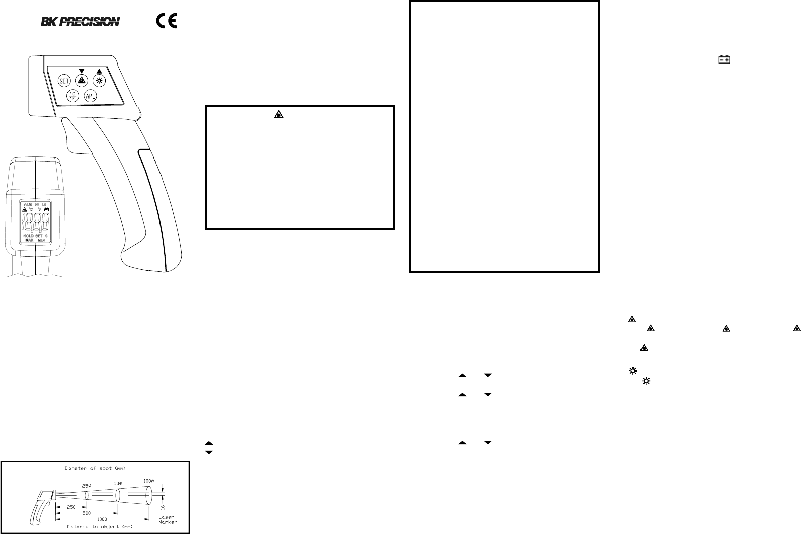
Field of View: 100mmØ at 1000mm (3.9"Ø at 39.0")
Spot size increases with distance from the probe tip as shown
(Spot Diameter measured at 90 % Energy)
OPERATING INSTRUCTIONS
Trigger
Pull the trigger to turn on the meter for measuring
temperature. Releasing trigger to stop measuring tem-
perature and automatically hold the display
reading, the meter power down automatically after 10
seconds.
Button function:
1. Set button
SET MODE & Numeric input key
"SET" annunciator appears when a numerical value can be
set ( during setting of ε, ALM Hi and ALM Lo).
key: The numerical value is increased.
key: The numerical value is reduced.
If either of these numerical value keys is held down, the
numerical value changes rapidly in the appropriate
direction.
The data will store in nonvolatile storage region while
after completing settings. In this mode the automatic power
-off feature is disable.
2. " " button
Press " " button to on the " " annunciator. If " "
annunciator is on, press trigger and the laser beam will turn
on and " " annunciator will blink. Releasing trigger to turn
off the laser beam.
3. " " button
Use " " button to select turn on or off the Back-Light
function.
4. °C/°F button
Readings are displayed in either degrees Celsius(°C) or
degrees Fahrenheit(°F). When the thermometer is turned
on. To change the temperature scale by pressing °C/°F
button .
5. APO button
It will auto power off for about 10 seconds.
Press "APO" button to disable . Auto Power-Off function
that HOLD indication disappears and press again to enable
APO function.
Press SET button switches the mode around the cycle ε !
ALM Hi ! ALM Lo ! MAX ! MIN ! HOLD.
HOLD :Releasing the trigger to stop measurement of
temperature, the HOLD indication appears,
and the measured temperature is held.
ε:The thermal emissivity of the object set using
the and keys. (refer to Table 1)
ALM Hi :The upper limit alarm temperature is set using
the and keys. When the measured
temperature is exceeded the Hi setpoint, the
beeper emits a discontinuous pulse tone and
"ALM Hi" is displayed.
ALM Lo :The lower limit alarm temperature is set using
the and keys. When the measured
temperature is below the Lo setpoint, the beeper
emits a continuous pulse tone and "ALM Lo"
is displayed.
MAX :The maximum temperature during measure-
ment is displayed.
MIN :The minimum temperature during measure-
ment is displayed.
MEASUREMENT CONSIDERATIONS
1. Theory of Measurement
Every object emits infrared energy in accordance with its
temperature. By measuring the amount of this radiant
energy, it is possible to determine the temperature of the
emitting object.
2. About Infrared
Infrared radiation is a form of light (electromagnectic
radiation), and has the property that it passes easily
through air while it is easily absorbed by solid matter.
With an emission thermometer which operates by detect-
ing infrared radiation accurate measurement is possible,
irrespective of the air temperature or the measurement
distance.
3. Emission Thermometer Structure
Infrared radiation which has been emitted from the object
is focused upon an infrared radiation sensor, via an optical
system. This includes a lens which is transparent to
infrared radiation. And 5.3µm cut off filter. The output
signal from the infrared radiation sensor is input to an
electronic circuit along with the output signal from a
standard tempeature sensor (Thermopile).
4. Emissivity
All objects emit invisible infrared energy. The amount of
energy emitted is proportional to the object's temperature
and its ability to emit IR energy. This ability, called
emissivity, is based upon the material that the object is
OPERATION
1.Take the protective cap off and then pull the trigger to
turn on the meter.
2.Point the lens at the object whose temperature is to be
measured.
3.Pull the trigger. Measurement is performed as long as
trigger is kept.
4.Referring to the spot size figure ,aim the laser beam at
the object whose temperature is to be measured.
5.Put the cap on to extend life of the sensor and to avoid
danger caused by wrong way to use laser.
NOTE: Although the field of measurement (or Field of View)
and the spot almost coincide, actually the field of
measurement corresponds to the diameter for 90%
optical response. The object whose temperature is
to be measured needs to be larger than the mea-
surement diameter (spot of size) by an adequate
margin at least 1.5 to 2 times larger.
made of and its surface finish. Emissivity values range
from 0.10 for a very reflective object to 1.00 for a black
body. Factory set emissivity value of 0.95, which cover
90% of typical applications.
5. If the surface to the measured is covered by frost or other
material, clean it to expose the surface.
6. If the surface to be measured is highly reflective, apply
masking tape or matt finish black paint to the surface.
7. If the meter seems to be giving incorrect readings check
the front cone. There may be condensation or debris
obstructing the sensor; clean per instructions in the
maintenance section.
Please Attention
"
#
For your convenience, we suggest you contact your BK
PRECISION distributor, who may be authorized to make
repairs or can refer you to the nearest service contractor.
If warranty cannot be obtained locally, please send the unit
to BK PRECISION Service Department, 22820 Savi
Ranch Parkway Yorba Linda, CA 92887, properly pack-
aged to avoid damage in shipment.
BK PRECISION Test Instruments only warrants prod-
ucts sold in the U.S.A. and its overseas territories. In other
countries each distributor warrants the BK PRECISION
products which it sells.
CUSTOMER SUPPORT 1-800-462-9832
Precision offers courteous, professional technical support
before and after the sale of their test instruments. The
following services are typical of those available from our
toll-free telephone number:
• Technical advice on the use of your instrument.
• Technical advice on special applications of your
instrument.
• Technical advice on selecting the best instrument for a
given task.
• Instrument for information on optional accessories for
your instrument.
• Information on instrument repair and recalibration
services.
• Replacement parts ordering.
• Information on other BK PRECISION instruments.
• Requests for a new BK PRECISION catalog.
• The name of your nearest BK PRECISION distributor.
Call toll-free 1-800-462-9832
Monday through Friday, 8:00 A.M. to 5:00 P.M.
Pacific Standard Time
22820 Savi Ranch Parkway Yorba Linda, CA 92887
© 2005 BK PRECISION
481-544-9-001 Printed in Taiwan
®
LIMITED ONE YEAR WARRANTY
BK PRECISION warrants to the original purchaser that
its product, and the component parts thereof, will be free
from defects in workmanship and materials for a period of
one year from the date of purchase.
BK PRECISION will, without charge, repair or replace,
at its option, defective product or component parts upon
delivery to an authorized BK PRECISION service con-
tractor or to the factory service department, accompanied by
proof of the purchase date in the form of a sales receipt.
Exclusions: This warranty does not apply in the event of
misuse or abuse of the product or as a result of unauthorized
alterations or repairs. It is void if the serial number is altered
, defaced or removed.
BK PRECISION shall not be liable for any consequential
damages, including without limitation damages resulting
from loss of use. Some states do not allow limitation of
incidental or consequential damages, so the above limitation
or exclusion may not apply to you.
This warranty gives you specific rights and you may have
other rights which vary from state-to-state.
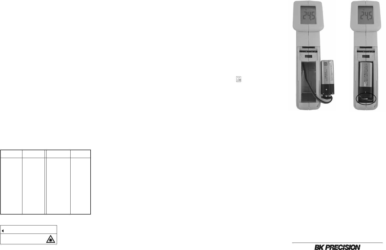
MAINTENANCE
Battery Replacement
1. Power is supplied by a 9 volt "transistor" battery. (NEDA
1604, IEC 6F22).
2. Pull off battery cover " ".
3. Remove the battery cover by gently sliding it towards the
bottom of the meter.
4. Remove and disconnect the old battery from the meter and
replace with a new unit. Wind the excess lead length and
put the top of battery beneath the battery chamber. Install
the battery and put the battery cover.
Cleaning
Periodically wipe the case with a damp cloth and deter-
gent, do not use abrasives or solvents.
LASER RADIATION - DO NOT STARE INTO BEAM
POWER OUT: < 1mW
WAVE LENGTH: RED (630-670nm)
LASER SAFETY CLASSIFICATION OF CLASS 2
EN 60825-1:1994/A11:1996/A2:2001
AVOID EXPOSURE
Laser radiation is emitted
from the APERTURE
CAUTION
(Table 1)
Asphalt 0.90 to 0.98 Cloth (black) 0.98
Concrete 0.94 Human skin 0.98
Cement 0.96 Lather 0.75 to 0.80
Sand 0.90 Charcoal (powder) 0.96
Earth 0.92 to 0.96 Lacquer 0.80 to 0.95
Water 0.92 to 0.96 Lacquer (matt) 0.97
Ice 0.96 to 0.98 Rubber (black) 0.94
Snow 0.83 Plastic 0.85 to 0.95
Glass 0.90 to 0.95 Timber 0.90
Ceramic 0.90 to 0.94 Paper 0.70 to 0.94
Marble 0.94
chromium oxides
0.81
Plaster 0.80 to 0.90 Copper oxides 0.78
Mortar 0.89 to 0.91 lron oxides 0.78 to 0.82
Brick (red) 0.93 to 0.96 Textiles 0.90
Substance Thermal Substance Thermal
emissivity emissivity
