Bk Cat17 User Manual
2017-01-19
User Manual: Bk Bk-Cat17 BK-Cat17_ pdf s
Open the PDF directly: View PDF ![]() .
.
Page Count: 76
- 00-Front-Cover
- 01-About-2017-v2
- 02-Power Supplies_BK_Cat17
- 03-Loads-2017-v1
- 04-Oscilloscopes_Cat17
- 05-Component Testers_BK_Cat17
- 06-Battery Testers_Cat17
- 07-Signal Generators_BK_Cat17
- 08-Spectrum_Analyzers_BK_Cat17
- 09-Multimeters_BK_Cat17
- 10-Electrical Testers_Cat17
- 11-Freq Counter & Device Prog_Cat17
- 12-Video Cable & Environmental_Cat17
- 13-Accessories_Cat17
- 14-Index-v2
- 15-Inside back cover_Cat17
- 16-Back-Cover
Product Catalog
Power Source & Sink
Signal Generation & Analysis
Component Testing

A Message from the President
It’s hard to imagine that B&K Precision has been serving the electronics industry for 65 years
now. From modest beginnings in a TV repair shop in Chicago, to today’s modern
manufacturing facilities in Taiwan, France, and China; R&D and marketing oices in the US,
Israel, and Romania; and distributors in over 50 countries, B&K has continued to innovate,
strengthen, and expand its product oerings.
Today’s electronic engineers and students may not recall the era of cathode ray tubes, but our
company started by making products to test, repair, and even rejuvenate CRT’s, extending the
life-span of TV sets. With broad changes in technology over the past six decades, we’ve
continued to develop diverse test and measurement solutions, including our DC & AC power
supplies, DC electronic loads, LCR meters, oscilloscopes and signal generators.
Many technical schools and universities around the world use our instruments, particularly our
function and arbitrary waveform generators, multimeters and oscilloscopes, to teach students
about fundamental and advanced electronics. Our commitment to education has led us to the
creation of a program that rewards enterprising schools and students with free test equipment.
As we look forward to the future with our global team of dedicated employees, we are
committed to continuing our work of developing new, exciting and dependable test equipment
to serve your ever changing testing needs.
"We are commited to
continuing our work of
developing new, exciting
and dependable
equipment to serve your
testing needs."
About B&K Precision
Sincerely
Victor Tolan
President and CEO
Introduction
For more than 60 years B&K Precision has
provided test and measurement solutions
to customers from wide-ranging fields
including research and development,
product design, industrial maintenance,
electronic field service, production line
testing, and the educational community,
among others. Universities and technical
schools worldwide have made our
instruments standard equipment in their
training programs.
Since 1951, the B&K Precision name has
represented quality, consistency, and value.
We take pride in supplying outstanding
products and excellent service at fair prices.
Full certification by the International
Organization for Standardization (ISO
9001:2008) reflects our commitment to
quality. Our mission is to maintain the
standards that have built our reputation,
develop new products to meet advancing
needs, and continue providing the products
and service our customers have come to
trust.
B&K oers a wide range of power test and
general purpose instruments. Our core
products include power supplies and DC elec-
tronic loads, battery testers, signal generators
(especially function and arbitrary generators),
component testers, oscilloscopes, spectrum
analyzers, and multimeters. We provide a full
complement of device programmers, video
and cable testers, electrical and battery
testers, and environmental testers. We also
supply a comprehensive array of probes,
leads, adapters, and additional accessories
that make testing easier.
We stand behind every product we ship.
Our warranties are valid worldwide, and
we provide global service and support to
guarantee your satisfaction. A growing
number of our instruments come with a
standard 3-year warranty, covering parts
and labor.
Our in-house technicians work directly with
you to provide any necessary calibrations or
repairs, ensuring optimum performance.
History
B&K Precision helped pioneer the electronic
testing industry, and like so many early
electronics firms, B&K started in a garage.
By 1948, when Americans had begun buying
televisions in large numbers, Chicago
entrepreneur Carl Korn and his partner Philip
Ban responded to the need for
maintenance of oen-unreliable sets.
Frustrated by a lack of equipment to easily
test television components, Ban and Korn
began making their own testing devices and
opened Central Television Service Company.
They soon had a thriving business selling
CRT rejuvenators and vacuum tube testers
to other television service shops. By 1951,
Korn had developed what would become B&K
Precision into a company that had branched
out into other areas of electronic testing and
measurement. B&K engineers broke new
ground, earning several patents in the field
of television test equipment, and rapidly
pushed the company to become a worldwide
leader in electronic measurement.

Power Supplies
Subheading
1
www.bkprecision.com
Global network of partner companies
B&K Headquarters
Yorba Linda,
California, USA
B&K Brasil
Sao Paolo, Brazil
Sefram
St. Etienne,
France
B&K R&D Center
Cluj, Romania
Itech
Nanjing, China
B+K Taiwan
Taipei, Taiwan
Dynamics Circuit
Singapore
B&K Precision group member Independent service center Service center location
In 1961, Carl Korn placed B&K Precision
under an umbrella corporation, Dynascan,
comprising a variety of electronics firms.
One of those companies, Cobra Electronics,
came to dominate the Citizen’s Band (CB)
radio phenomenon. Choosing to focus on
radios, Korn sold B&K Precision. Through an
ensuing series of ownership transitions B&K
continued to produce high-quality test and
measurement products.
In 1996, engineer Victor Tolan, headed up a
new ownership team for B&K Precision that
launched a greatly expanded product line.
The company also expanded upon its
American base to better serve international
customers. Company headquarters moved
to southern California to provide improved
service to Asia. In 2004, B&K expanded its
presence in Europe through the acquisition
of Sefram Instruments to better meet
customer needs in the region. With the
acquisition of Motech Industries’ instrument
division in 2011, we strengthened our
expertise in programmable linear and high
power switching power supplies.
B&K Precision has come a long way from its
days in Carl Korn’s garage, but holds fast to
the business ideals of innovation, flexibility,
and solid customer service that has guided
the company from its humble beginnings in
America, while reaching out to embrace the
rapidly expanding global marketplace. We
now provide service and support on four
continents, and our design team draws upon
resources in places as wide-ranging as
Romania, Israel, and Taiwan.
Americas – B&K Precision
Our headquarters in Yorba Linda, California
house most of our administrative and
executive functions including research and
design, customer service and repair, and sales
and marketing. The California warehouse
ships to North, Central, and South America,
and our service center provides our
customers with live, one-on-one support.
Our B&K Brasil oice supports our
expanding customer base in Brazil and other
South American countries.
Europe – Sefram
Our European customers have become
most familiar with B&K through our Sefram
subsidiary. Sefram’s oices in St. Etienne,
France currently support customers in
Europe, the Middle East, and Africa.
Asia – BK Taiwan, BK China and Itech
Our BK Taiwan and Itech plants primarily
design and manufacture programmable
power supplies and DC loads, and together
with the BK China oice provide distribution,
sales and service support for that region.
Engineers in China also know us through our
Itech brand. The independent service center
in Singapore services customers in Singapore,
Malaysia, Vietnam, and Indonesia.
Our distribution partners
An extensive network of independent
distributors oers B&K Precision products
around the globe. Visit our website to find
your local authorized distributor, and even
view available inventory from participating
distributors. You can buy in confidence,
knowing that all our products carry B&K’s
warranty, and worldwide service and
support.
As B&K Precision keeps growing, we continue
to uphold the standards we set more than a
half-century ago even as we find new answers
to our customers’ needs. Whether you require
measuring devices for a new venture; test
equipment to ensure standards adherence;
technology for teaching budding young
scientists—or instruments for test and
measurement challenges that depend on
quality and accuracy, B&K Precision
Corporation has solutions.
2
Video Library
View product overviews, demonstrations,
and application videos in English, Spanish
and Portuguese.
For an indepth and most up-to-date product information, support, news and more, visit www.bkprecision.com
Knowledge Base
Search and find answers to frequently
asked questions, plus a wealth of resources:
how-to guides, technical notes and
other articles.
Product Applications
Browse all of our supported product
and mobile applications.
3
www.bkprecision.com
CONTENTS
4 Power Supplies
6 ATE System & Application-Specific
11 General Purpose, Programmable
17 Basic & Education, Non-Programmable
19 AC Sources / Power Meters
22 DC Electronic Loads
24 Modular
26 Stand-Alone Programmable
29 Basic
30 Oscilloscopes
32 DSO/MSO
35 DSO
36 Handheld
37 Economy and Analog
38 Component Testers
40 Bench LCR
42 Handheld LCR
43 Handheld Capacitance, IC, ESR, Logic
44 DC Resistance
45 Battery Testers
45 Overview, Battery Analyzers
47 Frequency Response Analyzer
48 Signal Generators
51 True Arbitrary & Function Arbitrary
54 Digital (DDS)
55 Pulse
56 Analog
57 Spectrum Analyzers
60 Multimeters
65 Electrical Testers
66 Device Programmers & Counters
67 Video & Cable / Environmental Testers
69 Accessories (probes, leads, adapters)
72 Index
4
POWER SUPPLIES
Clean and reliable power

5
www.bkprecision.com
Power Supplies
Table of Contents
Category / Subcategory Page
ATE System & Application-Specific Power Supplies
ATE and LED 6 - 7
ATE and Solar 8 - 9
ATE and Automotive 10
General Purpose Programmable Power Supplies
Single Output 14 -16
Triple Output 11
Dual and Multi-Range 12 -13
Basic & Education Non-Programmable Power Supplies
Single Output 17
Triple Output 18
Multi-Range 18
Battery Eliminators and CV Power Supplies 18
AC Sources & Power Meters
Programmable AC Sources 19
Power Meters 20
Non-Programmable AC Sources 21
Power supply guide
Introduction to dierent power
supply types and the technology
behind them, plus related
terms, specications and
usage examples.
Visit “Applications” page at
bkprecision.com
Finding the right power supply
B&K Precision's power supply families cover basic to high
performance, 30 W to 5100 W, single or multiple outputs,
programmable and non-programmable, linear, switching, mixed
mode, multi range (auto), dual range, as well as support for all
industry standard computer interfaces such as USB, GPIB,
and LAN.
Power Supplies
ATE System Power & LED
6
*All models except for high voltage models 9184B and
9185B
9170B/9180B Series Programmable Dual-Range DC Power Supplies
Output rating No. of
outputs
Load regulation Ripple and noise*
normal mode
Programming/
readback resolution Model
Low Range High Range Voltage Current Voltage Current Voltage Current
0-10 V, 0-10 A 0-20 V, 0-5 A 1≤ 0.01 %+1 mV ≤ 0.01 %+250 uA ≤ 0.35 mVrms/≤ 3 mVpp ≤ 2 mA rms < 1 mV < 1 mA 9171B
0-35 V, 0-3 A 0-70 V, 0-1.5 A 1≤ 0.01 %+1 mV ≤ 0.01 %+250 uA ≤ 0.5 mVrms/≤ 5 mVpp ≤ 2 mA rms < 2 mV < 0.1 mA 9172B
0-10 V, 0-10 A 0-20 V, 0-5 A 2≤ 0.01 %+1 mV ≤ 0.01 %+250 uA ≤ 0.35 mVrms/≤ 3 mVpp ≤ 2 mA rms < 1 mV < 1 mA 9173B
0-35 V, 0-3 A 0-70 V, 0-1.5 A 2≤ 0.01 %+1 mV ≤ 0.01 %+250 uA ≤ 0.5 mVrms/≤ 5 mVpp ≤ 2 mA rms < 2 mV < 0.1 mA 9174B
0-18 V, 0-8 A 0-36 V, 0-4 A 1≤ 0.01 %+1 mV ≤ 0.01 %+250 uA ≤ 0.35 mVrms/≤ 3 mVpp ≤ 2 mA rms < 1 mV < 1 mA 9181B
0-10 V, 0-20 A 0-20 V, 0-10 A 1≤ 0.01 %+1 mV ≤ 0.01 %+250 uA ≤ 0.35 mVrms/≤ 3 mVpp ≤ 2 mA rms < 1 mV < 1 mA 9182B
0-35 V, 0-6 A 0-70 V, 0-3 A 1≤ 0.01 %+1 mV ≤ 0.01 %+250 uA ≤ 0.5 mVrms/≤ 5 mVpp ≤ 2 mA rms < 2 mV < 0.2 mA 9183B
0-100 V, 0-2 A 0-200 V, 0-1 A 1≤ 0.01 %+1 mV ≤ 0.01 %+250 uA ≤ 1.5 mVrms/≤ 15 mVpp ≤ 2 mA rms < 10 mV < 0.1 mA 9184B
0-400 V, 0-0.5 A 0-600 V, 0-0.35 A 1≤ 0.01 %+1 mV ≤ 0.01 %+250 uA ≤ 4.5 mVrms/≤ 45 mVpp ≤ 2 mA rms < 10 mV < 0.01 mA 9185B
*Ripple and noise (20 Hz - 20 MHz)
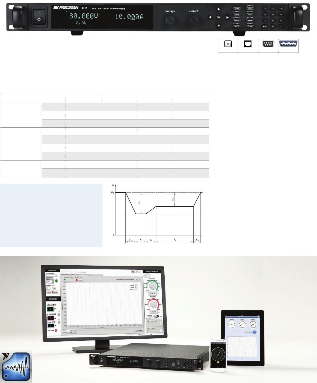
The 9170B/9180B Series programmable DC
power supplies oer industry leading
performance, designed to meet the most
demanding applications in R&D, design
verification and production test. All 9 models
deliver clean, stable and precise output
power due to the supplies’ exceptionally low
ripple and noise, low temperature coeicient,
excellent regulation and fast transient
response time characteristics. Additionally,
the 9170B/9180B Series oers unique features
not typically found in other power sources on
the market, such as versatile LED test modes,
modular interface card slots, automatic range
selection, and an optional 8-bit bidirectional
digital I/O interface.
Features & Benefits
Single and dual output models with up
to 210 W output power
Exceptionally low ripple and noise
(e.g. 0.35 mVrms/3 mVpp for model 9171B)
Fast transient response time of
< 50 us most models
Fast command processing time, less than
10 ms
Dual range output with automatic
range selection*
Programmable voltage and current
slew rates
Front and rear panel output
Remote sense terminals
List mode for executing up to 10 stored
test sequences with a maximum of 150
steps in total
Store and recall up to 10 power settings
Overvoltage/overcurrent/
overtemperature protection
(OVP/OCP/OTP) and key-lock function
Application soware providing remote
control capability included
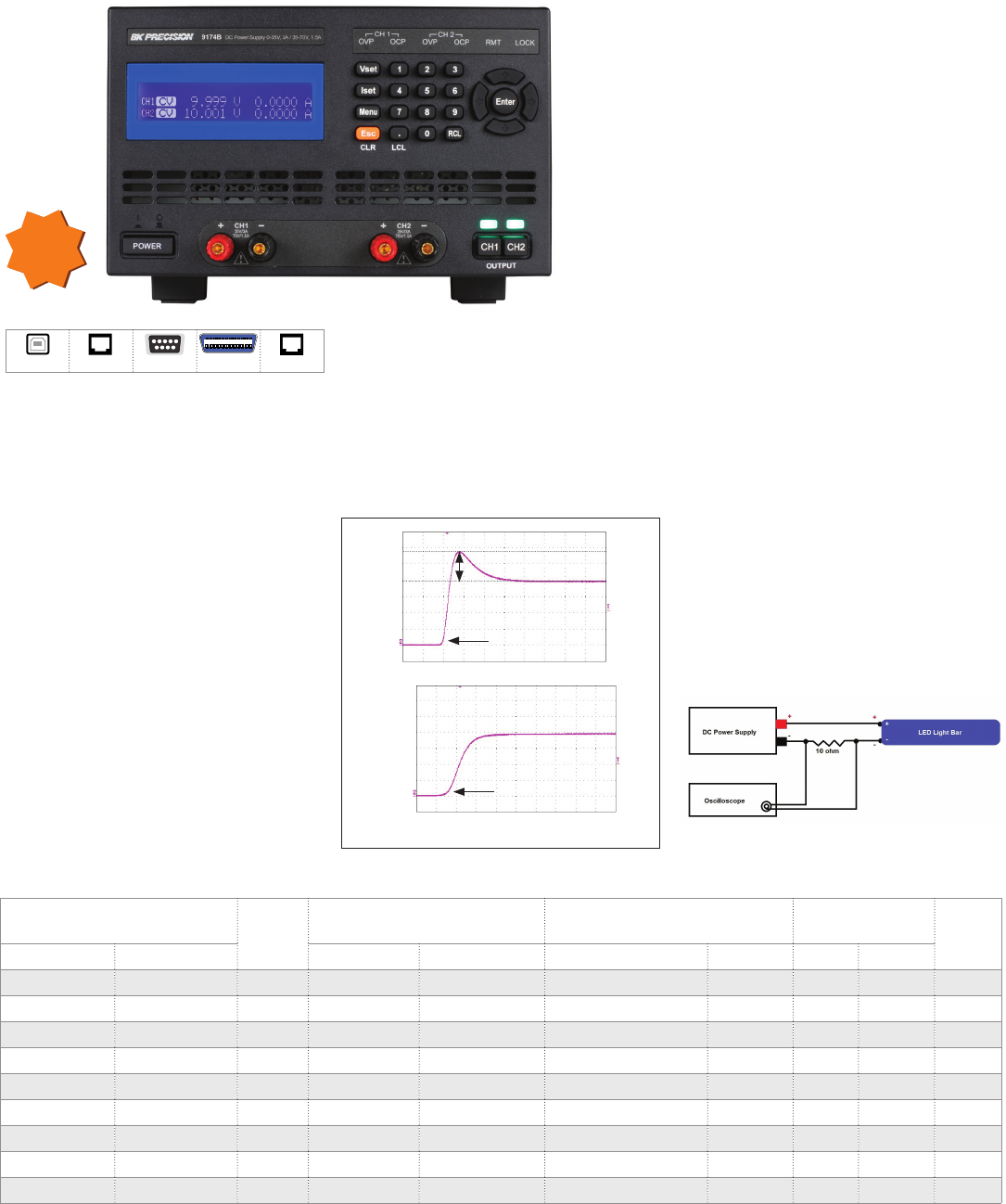
LED mode
With LED mode active, inrush current will be
eliminated or minimized to protect the UUT.
Inrush current
Output ON
LED mode OFF
Output ON
LED mode ON
Current ow during power up with LED mode enabled Example LED test setup
NEW
Model 9174B
USB LAN* RS232* GPIB* RS485*
* optional
7
www.bkprecision.com
Power Supplies
ATE System Power
The B&K Precision XLN Series are compact,
programmable, single-output DC power
supplies, suitable for a wide range of
applications. Comparable supplies from
other manufacturers primarily address the
ATE market only, while the XLN Series are
designed for both benchtop users and
system integrators.
For benchtop applications, these power
supplies oer built-in voltage and current
meters displaying setting and output values
concurrently, as well as an intuitive user
interface with full keypad and rotary knob.
Standard USB & RS485 and optional GPIB &
LAN interfaces combined with fast average
Features & Benefits
Compact, high density, 1U package
USB interface (standard) and GPIB/LAN
(optional)
External analog programming interface
List mode for executing up to 150 step test
sequences from instrument memory
Fast command processing time < 50 ms
Programmable voltage and current slew
rate allow for "so starting" of loads
Easy to configure master/slave mode for
series or parallel connection up to 4 units
Extensive protection features: OVP,
OCP, OPP, and key-lock function
100 - 240 V universal AC input with power
factor corrections
Control up 31 power supplies from one
PC via RS485 interface
Features High current
XLN models
High voltage
XLN models
Auxiliary output 5 V / 1 A -
Master/Slave
operation Parallel/
Series Parallel Only
Display
resolution 1 mV/1 mA 10 mV/1 mA
Analog
programming √ √
Analog
monitoring - √
Specifications XLN3640 XLN6024 XLN8018 XLN10014 XLN15010 XLN30052 XLN60026
GPIB & LAN version XLN3640-GL XLN6024-GL XLN8018-GL XLN10014-GL XLN15010-GL XLN30052-GL XLN60026-GL
Output voltage 0-36 V 0-60 V 0-80 V 0-100 V 5 -150 V 5 - 300 V 5 - 600 V
Output current 0-40 A 0-24 A 0-18 A 0-14.4 A 0.04 - 10.4 A 0.02 - 5.2 A 0.01 - 2.6 A
Load
regulation
Voltage ≤ 8 mV ≤ 8 mV ≤ 10 mV ≤ 12 mV ≤ 17 mV ≤ 32 mV ≤ 62 mV
Current ≤ 8 mA ≤ 7 mA ≤ 6.5 mA ≤ 6 mA ≤ 0.1% + 30 mA ≤ 0.1% + 15.6 mA ≤ 0.1% + 7.8 mA
Programming
accuracy
Voltage 0.05% + 10 mV 0.05% + 15 mV 0.05% + 20 mV 0.05% + 25 mV 0.05% + 75 mV 0.05% + 150 mV 0.05% + 300 mV
Current 0.05% + 10 mA 0.05% + 18 mA 0.05% + 7 mA 0.05% + 6 mA 0.1% + 30 mA 0.1% + 15.6 mA 0.1% + 7.8 mA
Ripple and
noise
Voltage ≤ 5 mVrms/
≤ 60 mVpp ≤ 6 mVrms/
≤ 70 mVpp ≤ 7 mVrms/
≤ 80 mVpp ≤ 8 mVrms/
≤ 80 mVpp ≤ 10 mVrms/
≤ 100 mVpp ≤ 25 mVrms/
≤ 150 mVpp ≤ 50 mVrms/
≤ 300 mVpp
Current ≤ 90 mA ≤ 70 mA ≤ 50 mA ≤ 40 mA ≤ 15 mA ≤ 10 mA ≤ 5 mA
command processing times of less than
50 ms make the XLN Series ideal for ATE
applications. The XLN Series support SCPI
IEEE488.2 and come with LabVIEW™
drivers and application soware.
XLN Series Family of High Density System Power Supplies
pwrApp for iPad, iPhone & iPod touch
The GPIB/LAN interface also provides a
built-in web server. This allows users to
configure, control, or monitor the basic
settings of the power supply from a remote
computer using a web browser.
Voltage and current values can also be
programmed through the analog interface by
applying a voltage or current source. High
voltage models also provide additional
monitoring functions such as output voltage/
current montoring and indicators for
regulation mode (CC or CV) and fault alarms.
Generate, save, and load program lists. View
output characteristic curves and export data to a le.
* optional
USB LAN* GPIB*
High current High voltage
Power Supplies
ATE System Power & Solar
8
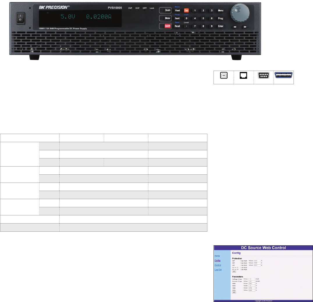
PVS Series High Power Programmable DC Power Supplies
The PVS Series delivers programmable output power up to 5.1 kW and is well suited for bench
use, ATE systems integration, R&D, design verification, production test, and high voltage
testing. The low-noise characteristic of the PVS Series makes these instruments particularly
ideal for motor inverter testing. When operated with the optional SAS soware, these power
supplies can be used for solar array testing applications.
Model PVS60085 PVS60085MR PVS10005
Output ratings
Voltage 600 V 1000 V
Current 8.5 A 5 A
Power 5100 W 3000 W 5000 W
Load regulation Voltage 60 mV 100 mV
Current 8.5 mA 5 mA
Ripple & noise
(20 Hz to 20 MHz)
Voltage ≤ 100 mVrms / ≤ 500 mVpp ≤ 100 mVrms / ≤ 600 mVpp
Current 15 mA 10 mA
Programming
accuracy
Voltage 400 mV 700 mV
Current 0.03% + 3.5 mA 0.03% + 2 mA
Dimensions (W x H x D) 420 mm x 88 mm x 532 mm
Weight 14.6 kg
Model PVS60085MR is a multi-ranging supply allowing any combination of the rated voltage and current up to the
maximum output power of 3000 W.
Features & Benefits
Compact, high power density, 2U package
Convenient single-phase AC input
configuration
Fast transient response time of ≤ 0.5 ms
Standard USB (virtual COM), RS232,
GPIB and LAN interfaces supporting SCPI
commands
External analog programming and
monitoring interface
Extensive protection features: OVP, OCP,
OPP, OTP, foldback protection mode, and
key-lock function
Application software
PC soware is provided for front panel emulation, generating and executing test sequences or
logging measurement data without the need to write source code.
Save and load list files to/from the power supply’s internal memory.
Create an unlimited number of external list files to be executed from PC memory. Save and
recall list files to/from the PC.
Log voltage, current, and power values as well as time stamp, CV/CC, and output status.
Remote monitoring on iOS, Android, or Windows 8 compatible tablets or smart phones via
NI Data Dashboard for LabVIEW apps. Quickly develop a custom dashboard consisting of
one (smart phone) or several (tablet) indicators, charts, or gauges to monitor your
power supply.
Web server interface
The PVS Series models provide a built-in web
server that allows users to configure, control,
or monitor the basic settings of the power
supply from a remote computer using a
web browser.
USB LAN RS232 GPIB
9
www.bkprecision.com
Power Supplies
ATE System Power & Solar
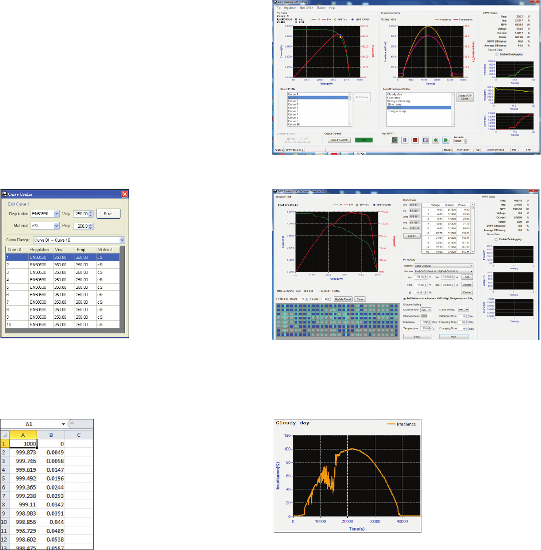
Features
Test to EN50530, Sandia, and NB/T32004 standards
Monitors and logs real-time voltage, current, power, MPPT
eiciency, and average MPPT eiciency
Simulate I-V curve under dierent weather conditions during a day
User-definable irradiance profile
Generate a custom I-V curve with up to 4,096 data points
Shadow I-V curve simulation
Comprehensive built-in list of defined I-V curves of PV modules
from various manufacturers for simulation
Solar Array Simulation (SAS) Soware Option
Solar inverter designers need to verify their inverter is capable of delivering the maximum power available from solar modules. The I-V curve
of solar cells can be influenced by various weather conditions such as a cloudy day. Combined with the SAS application soware, PVS users
can easily simulate the I-V curve of dierent arrays under various irradiance conditions while measuring and validating the eectiveness of the
inverter’s MPPT algorithm. The PVS power supply outputs points on the I-V curve in 1 ms intervals to test the inverter’s MPPT eiciency.
Generate an I-V curve manually via
a 4,096-point voltage and current
table with Notepad or MS Excel
and load it in the soware.
Use any of the soware’s
built-in irradiance profiles or
generate your own
point-by-point irradiance
profile.
Create shadow I-V curves by specifying shadowed cells of PV module
and setting cloud direction, change time, and other parameters to
simulate shadow and cloudy dynamic conditions.
Automatically generate the I-V curve of solar array in the soware by
specifying the regulation standard, material type of the solar array,
maximum voltage point (Vmp), and maximum power point (Pmp).
Shadow I-V curve simulationI-V curve generation to regulation standards
User-defined I-V curve Built-in irradiance profiles
Power Supplies
ATE System Power & Automotive
10
9115 Series 1200 W Multi-Range DC Power Supplies
Any 9115 Series model can replace several supplies on your bench or in your rack. Unlike conventional supplies with fixed output ratings, these
multi-range power supplies automatically recalculate voltage and current limits for each setting, providing full output power in any Volt/Amp
combination within the rated voltage and current limits.
Model 9115 9115-AT 9116 9117
Output ratings
Voltage 80 V 150 V 80 V
Current 60 A 30 A 120 A
Power 1200 W 3000 W
Load
regulation
Voltage 0.01 % + 5 mV 0.05 % + 30 mV
Current 0.1 % + 10 mA 0.1 % + 30 mA
Ripple
(20 Hz - 20 MHz)
Voltage ≤ 60 mVpp ≤ 80 mVpp
Current 100 mArms 40 mArms 120 mArms
Programming/
Readback
accuracy
Voltage 0.02 % + 30 mV 0.05 % + 30 mV
Current 0.1 % + 60 mA 0.2 % + 30 mA 0.2 % + 120 mA
Model 9115-AT automotive test functions
The 9115-AT provides automotive power
test waveforms compliant to DIN 40839 and
ISO 16750-2 standards that can simulate
common test conditions for electrical and
electronic devices installed in automobiles.
Motor startup curve test
Features & Benefits
Multi-range operation
Compact, high density, 1U rackmount
form factor (2U for 9117)
High programming and
readback resolution
Adjustable voltage slope
(rise and fall times)
Sequence programming (internal list
mode for models 9115, 9115-AT, and 9116)
Standard USB (USBTMC-compliant),
RS232, GPIB, RS485, and LAN (9117 only)
interfaces supporting SCPI commands for
remote control
Analog interface with control and
monitoring functions
Overvoltage protection (OVP), overpower
protection (OPP), overtemperature
protection (OTP), and key-lock function
B&K Precision’s application soware for selected power supplies
integrate with National Instrument’s NI Data Dashboard for
LabVIEW, allowing you to remotely monitor your power supply on
iOS, Android, or Windows 8 compatible tablets or smartphones.
This app enables users to quickly develop a custom dashboard
consisting of one or several indicators, charts, or gauges.
Supports NI Data
Dashboard for
LabVIEW
* 9117 only
USB LAN* RS232 GPIB
11
www.bkprecision.com
Power Supplies
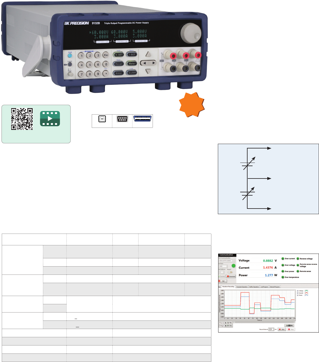
General Purpose - Triple Output
Features & Benefits
Three independent, fully programmable
and electrically isolated outputs
Tracking mode to adjust voltage and
current settings for all channels
simultaneously
Connect any two or all three channels in
series or parallel to produce higher
voltages or currents
Low noise, linear regulation
Standard USB (USBTMC-compliant),
RS232, & GPIB interfaces (9130B Series)
Communicate via USB interface using
the included USB to TTL serial adapter
(9129B)
Overvoltage protection (OVP) and
overtemperature protection (OTP)
Bipolar output configuration
-
+
+VDC
-VDC
Channel 1
Channel 2
O VDC
Model 9129B 9130B 9131B 9132B
Output ratings
Ch1 &
Ch2 30 V, 3 A 30 V, 3 A 30 V, 6 A 60 V, 3 A
Ch3 5 V, 3 A 5 V, 3 A 5 V, 3 A 5 V, 3 A
Power 195 W 195 W 375 W 375 W
Ripple and noise
Voltage ≤ 5 mVp-p / 1 mVrms ≤ 1 mVrms
Current ≤ 6 mArms ≤ 3 mArms ≤ 5 mArms (ch1/ch2)
≤ 4 mArms (ch3) ≤ 4 mArms
Programming
resolution
Voltage 10 mV / 1 mA 1 mV / 1 mA
Current
Load regulation CV < 0.02% + 4 mV ≤0.01% + 3 mV
CC < 0.2% + 3 mA ≤0.1% + 3 mA
Remote interface USB Adapter USB (USBTMC), RS232, GPIB
Memory locations 29 36
Remote sense -- √
Output timer -- √
PC software is provided for front panel emulation,
generating and executing test sequences or logging
measurement data without the need to write source
code.
The independent and isolated outputs can be
used to create positive and negative outputs
between channels 1 and 2. This feature is useful
for powering bipolar circuits and devices.
9129B & 9130B Series Triple Output DC Power Supplies
These triple output linear programmable DC power supplies feature isolated outputs that
can be adjusted independently or combined in series or parallel to output higher voltage or
current. Additionally, these supplies can operate in tracking mode with user-configurable
ratios between channels.
Scan QR code to watch
9130B Series overview video
Application software
Users can control the power supplies using SCPI command or via the provided application
soware, which supports test sequence generation and logging.
9130B Series only
USB RS232 GPIB
NEW
Power Supplies
General Purpose - Dual & Multi-Range
12
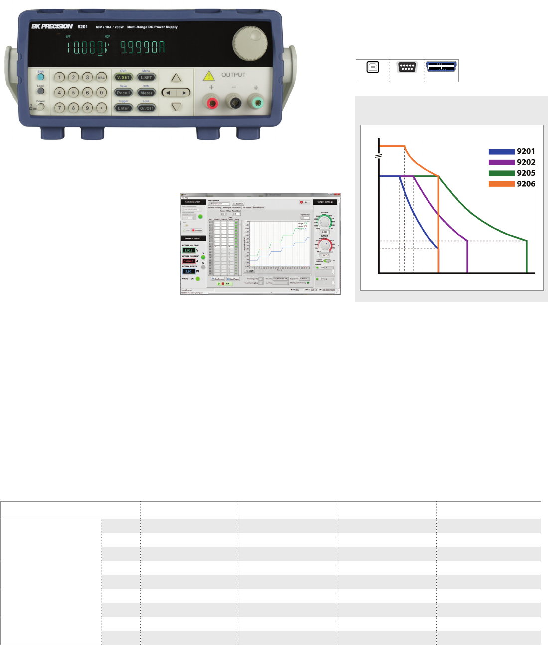
Model 9201 9202 9205 9206
Output ratings
Voltage 60 V 60 V 60 V 150 V
Current 10 A 15 A 25 A 10 A
Power 200 W 360 W 600 W 600 W
Load regulation Voltage ≤ 0.01%+5 mV ≤ 0.01%+8 mV ≤ 0.01%+15 mV ≤ 0.01%+15 mV
Current ≤ 0.05%+4 mA ≤ 0.05%+6 mA ≤ 0.1%+10 mA ≤ 0.05%+10 mA
Ripple and noise
(20 Hz - 20 MHz)
Voltage ≤ 8 mVpp ≤ 15 mVpp ≤ 20 mVpp ≤ 50 mVpp
Current ≤ 6 mArms ≤ 8 mArms ≤ 15 mArms ≤15 mArms
Programming/readback
accuracy
Voltage ≤ 0.03%+5 mV ≤ 0.03%+5 mV ≤ 0.03%+5 mV ≤ 0.03%+20 mV
Current ≤ 0.1%+10 mA ≤ 0.1%+15 mA ≤ 0.1%+25 mA ≤ 0.1%+25 mA
Any 9200 Series model can replace several
supplies on your bench or in your rack.
Unlike conventional supplies with fixed
output ratings, these multi-range power
supplies automatically recalculate voltage
and current limits for each setting, providing
full output power in any Volt/Amp
combination within the rated voltage and
current limits.
9200 Series Multi-Range Programmable DC Power Supplies
Features & Benefits
Multi-range operation
High programming and
readback resolution
List mode programming
Standard USB, RS232, and GPIB interfaces
for remote control
Remote sense
Overvoltage protection (OVP), overcurrent
protection (OCP), and overtemperature
protection (OTP)
Multi-range operation
Traditional power supplies with rectangular
output characteristics are only able to deliver
maximum output power at one voltage/
current point. The multi-ranging 9200 Series
provides greater flexibility over traditional
power supplies by extending operating areas.
For example, the 9206 can operate at 150
V/4 A, 60 V/10 A, or any other point on the
maximum power curve. These wide ranges
of voltage and current allow users to replace
multiple traditional power supplies on a
bench or system rack.
Application software
PC soware is provided for front panel
emulation, generating and executing test
sequences or logging measurement data
without the need to write source code.
Log voltage, current, and power values
as well as timestamp, CV/CC mode, and
output status
Save and load list files to and from the
power supply’s internal memory or a PC
Remote monitoring on iOS, Android,
or Windows 8 compatible tablets or
smartphones via NI Data
03.3 A 6 A 10 A 15 A 20 A
Current
Voltage
150 A
60 A
24 V
20 A
600 W 600 W
360 W
200 W
9200 Series
output characteristics
USB RS232 GPIB
13
www.bkprecision.com
Power Supplies
General Purpose - Dual & Multi-Range
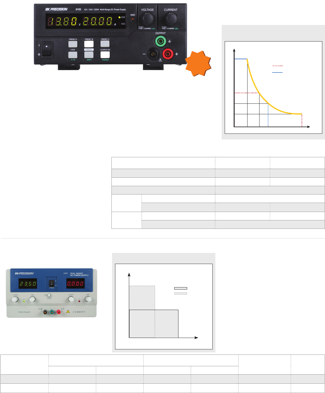
9103 & 9104 Multi-Range DC Power Supplies
1737 & 1747 Dual-Range DC Power Supplies
Features & Benefits
Low ripple and noise
Excellent regulation
Constant voltage (CV) and constant
current (CC) operation
Two 4-digit LED displays provide good
visibility in bright or low light
RS232 interface
Automatic recall of last settings on
power up
Power (W) Voltage (V) Current (A) Ripple & Noise Model
Range 1 Range 2 Range 1 Range 2
90 / 120 0 -30 0 - 60 0 - 3 0 - 2 1 mVrms 1737
350 / 300 0 -35 0 - 60 0 - 10 0 - 5 1 mVrms 1747
Features & Benefits
Multi-ranging operation
Rotary encoder control for precise voltage
and current setting
Save up to 3 user-defined voltage and
current presets for quick recall
Output On/O control
This family of eicient and compact DC power
supplies oers multi-ranging capabilities,
allowing the user to provide higher voltage
or higher current compared to conventional
power supplies of the same power rating.
By providing expanded operational ranges
of voltage and current, users can save both
money and space by replacing several power
supplies with one multi-range power supply.
Model 1747
Model 9103 / 9104
output characteristics
Current
Voltage
84V
42V
32V
16V
3.8A 7.6A 10A 20A
9103
9104
320 W Maximum
Power Curve
0
Model 9103 9104
Variable output voltage 0 – 42 V 0 – 84 V
Variable output current 0 – 20 A 0 – 10 A
Max power 320 W
Ripple and
noise
Voltage ≤80 mVpp / ≤8 mVrms
Current ≤200 mA ≤50 mA
Voltage
regulation
Load (0-100% rated current) ≤120 mV ≤100 mV
Line (90-264 VAC variation) ≤10 mV
NEW
Step and ramp programming function
Analog remote control function
USB interface
Remote sense terminal
Output on-o switch and control panel
lock button for safer operation
Overvoltage, overtemperature, overload,
and short circuit protection
1747 Operating range
0 5 10
60
35
Current (A)
Voltage (V)
Range 1
Range 2
Power Supplies
General Purpose - Single Output
14
Features & Benefits
16 user programmable preset outputs
Controllable output On/O switch
Communicate via USB interface using the
included USB to TTL serial adapter
10 mV/10 mA display resolution
Bright VFD display
Closed case calibration for simple,
uninterrupted operation low ripple
and noise
Excellent temperature stability
Serial interface cable and remote control
soware included
OVP, OCP, and OTP protection
Programmable DC Supplies
Models 1785B, 1786B, 1787B, and 1788 are
programmable DC power supplies oering a
new level of "ease-of-use" and
programmability in a low-cost package.
Power (W) Voltage (V) Current (A) Interface Weight Dimensions (W x H x D) Model
90 0-18 0-5
USB* 5 kg 214.5 x 88.2 x 354.6 mm
1785B
96 0-32 0-3 1786B
108 0-72 0-1.5 1787B
192 0-32 0-6 1788
Power (W) Voltage (V) Current (A) Ripple & noise
(mVpp) Weight Dimensions
(W x H x D) Model
300 1-60 0-5
50 2.4 kg 200 x 90 x 208 mm
1685B
360 1-36 0-10 1687B
360 1-18 0-20 1688B
900 1-60 0-15 100
3.2 kg 200 x 90 x 275 mm
1902B*
960 1-16 0-60 50 1900B*
960 1-32 0-30 1901B*
Models 1685B, 1687B, 1688B, 1900B, 1901B
and 1902B are laboratory grade switching DC
power supplies with high current output in a
small, lightweight form factor. They provide
various configurations of high output voltage
or high output current and feature rotary
encoder control knobs, which make setting
voltage and current fast and precise. Dual
action push buttons allow the user to set both
coarse and fine, voltage and current levels.
Features & Benefits
Automatic CV (constant voltage)/ CC
(constant current) crossover operation
Lightweight and compact
Rotary encoder control for precise
voltage and current setting
Save up to 3 user-defined voltage and
current presets for quick recall
Analog remote control function
Remote sensing terminal (model 1900B)
Overvoltage, overtemperature, and
overload protection
USB interface with PC soware for
remote control and external timed
programming
1685B Series & 1900B Series Switching DC Power Supplies
*USB to TTL serial adapter
USB
* Order model 190x-220 V for 220 V AC input conguration
15
www.bkprecision.com
Power Supplies
General Purpose - Single Output
The 9120A and 9150 Series are high
performance linear-regulated programmable
DC power supplies that provide excellent
performance and features not found in other
power supplies of the same price category.
These power supplies are designed for
applications in design verification,
production testing, or university labs where
the user requires clean, reliable power
combined with high resolution/accuracy and
a fast transient response time.
Features & Benefits
Very low ripple and noise due to
linear regulation
Excellent display resolution
Fast transient response time
(<150 s all models)
Programmable via USB using SCPI
compatible command set
List mode operation for
increased throughput
Intelligent fan speed control for
quiet operation
For bench use or rack mountable
Closed case calibration
Built-in 5 1/2 digit DVM and milliohm
meter supporting 4 wire measurements.
Application software
The included application soware supports
front panel emulation and allows users to
generate simple test sequences without the
need to write source code.
Software test sequence setup
Power (W) Voltage (V) Current (A) Load regulation Ripple & noise Weight Dimensions Model
86.4 0-72 V 0-1.2 A <0.01% +2 mV
<0.05% +0.3 mA < 5 mVpp
9 kg
214.5 x 88.2 x 354.6 mm
9124
96 0-32 V 0-3 A <0.01% + 2 mV
<0.05% +1 mA
< 4 mVpp 9120A
100 0-20 V 0-5 A < 3 mVpp 9121A
150 0-60 V 0-2.5 A <0.01%+ 2 mV
<0.05% +0.5 mA < 5 mVpp
9.6 kg
9122A
150 0-30 V 0-5 A <0.01%+ 2 mV
<0.05% +1.5 mA < 4 mVpp 9123A
540 0-20 V 0-27 A <0.01% +1 mV
<0.1% +5 mA 0.005% + 3 mVpp 29 kg 429 x 88.2 x 458.9 mm
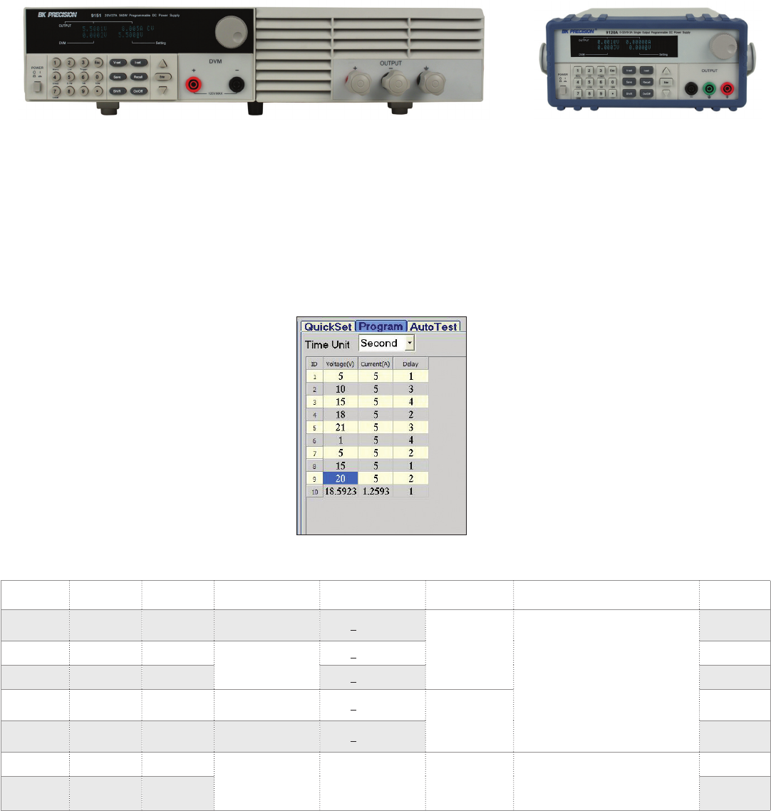
9151
540 0-30 V 0-18 A 9152
Model 9151 Model 9120A
9120A & 9150A Series Programmable Power Supplies
The series’ digital port oers a variety of
configurations. The port provides Digital Input,
external Trigger and Remote Inhibit (RI)
functionality. The RI mode can be used for
turning several power supplies On/O
simultaneously.
Power Supplies
General Purpose - Single Output
16
Features & Benefits
RS232 interface standard
Application soware providing data
logging capability
Output on/o button
Over voltage protection
Constant voltage and constant current
(current limiting) operation
Large easy-to-read LCD displays
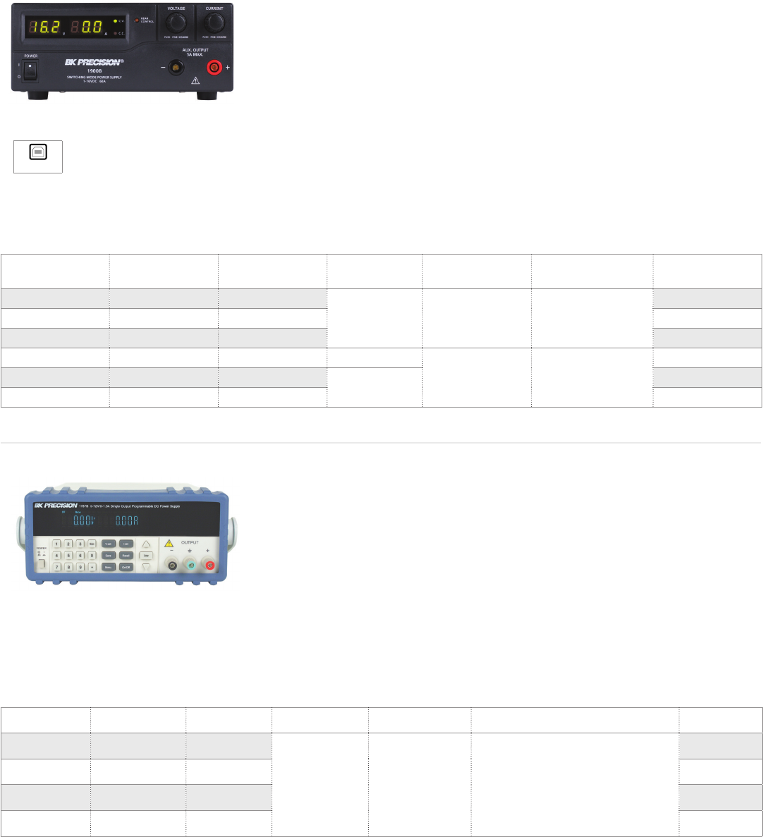
The 1696, 1697, and 1698 DC switching mode
programmable power supplies generate
200 W of output power at a lower cost than
traditional linear power supplies.
The RS232 interface allows you to remotely
control the power supply or program a
sequence of dierent voltages and current
limits that can be used in an automated
test application.
Power (W) Voltage (V) Current (A) Interface Display (meter) Ripple & noise
(mVrms) Weight Dimensions (W x H x D) Model
27 30 0-0.9 RS232 Dual 4-digit LED 14 kg 140 x 158 x 318 mm 1739
198 1-60 0-3.3
RS232,
RS485*
4-digit display
ammeter,
voltmeter, and
power meter
25 mVpp 3 kg 193 x 98 x 215 mm
1698
200 1-20 10 1696
200 1-40 0-5 1697
The B&K Precision model 1739 is a high
resolution, low current DC power source that
exhibits excellent regulation and low
ripple characteristics. This power supply
is well suited for electrical and electronics
applications requiring precise levels of low
current including 4-20 mA current loop
testing and calibration.
Features & Benefits
Low current ripple and noise
(<0.4 mArms)
Low 1 mA settable current limit with
0.1 mA resolution
Output on/o button
LED indication for CV and CC modes
Automatic recall of saved voltage and
current settings upon power up
RS232 interface
Power-on self test
1739 30V/1A Low Current High Resolution DC Power Supply
*via optional RS232 to RS485 adapter
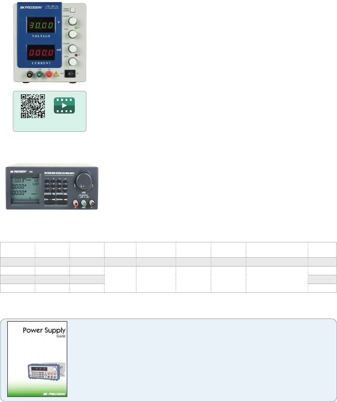
1696 Series Programmable DC Switching Power Supplies
Introduction to dierent power supply types and the technology behind them,
plus related terms, specifications and usage examples.
For more guides and applications, visit: bkprecision.com/product-applications
Power Supply Guide
Scan QR code to watch
1739 overview video
17
www.bkprecision.com
Power Supplies
Basic & Education
Power
(W) Voltage (V) Current (A) Display (meter) Number of
outputs Type Weight Dimensions
(W x H x D) Model
12 W 3.3 V/4.5 V/6 V/7.5 V/
9 V/12 V (fixed) 1 A None
1
Battery eliminator 0.4 kg 88.9 x 50.8 x 139.7 mm 1513
30 W 0-30 V 0-1 A Dual Analog CV/CC mode supply 3.6 kg 140 x 158 x 318 mm 1710A*
36 W 3.3 V/4.5 V/6 V/7.5 V/
9 V/12 V (fixed) 3 A None Battery eliminator 0.4 kg 88.9 x 50.8 x 139.7 mm 1514
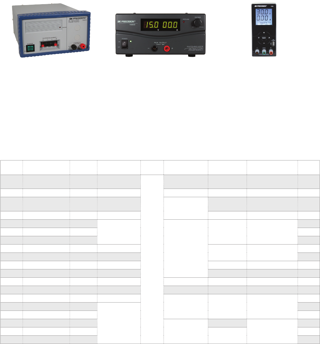
55 W 13.8 V (Fixed) 4 A None 2.65 kg 92 x 160 x 170 mm 1680
90 W 0-18 V 0-5 A
Dual 3-digit LED
CV/CC mode supply
7.4 kg 115 x 205 x 270 mm
1621A
90 W 0-60 V 0-1.5 A 1623A
90 W 0-30 V 0-3 A 1627A
90 W 0-30 V 0-3 A Dual Analog 4.7 kg 140 x 158 x 318 mm 1730A*
90 W 0-30 V 0-3 A Dual 4-digit LED 1735A*
108 W 1-36 V 0-3 A 3-digit display 2 kg 70 x 150 x 250 mm 1550
120 W 0-60 V 0-2 A Dual 4-digit LED 5.4 kg 140 x 158 x 318 mm 1715A*
166 W 13.8 V (Fixed) 12 A None Battery eliminator 6.75 kg 124 x 216 x 292 mm 1682A
168 W 14 V 12 A @ 14 V Dual Analog CV mode supply 5.45 kg 124 x 216 x 292 mm 1686A
200 W 1-20 V 0-10 A Dual 3-digit LED
CV/CC mode supply 3 kg 203 x 114 x 274 mm
1665
200 W 1-40 V 0-5 A
Dual 3-digit LED
1666
198 W 1-60 V 0-3.3 A 1667
600 W 3-15 V 40 A
CV mode supply
3.5 kg
220 x 110 x 300 mm
1692
900 W 1-15 V 60 A 5.8 kg 1693
900 W 30 V 30 A 1694
*CuL
CV/CC Power Supplies
Constant voltage/constant current (CV/CC)
power supplies are one of the most popular
types of power supplies. These supplies allow
users to adjust both the voltage and current.
Similar to constant voltage mode where the
set voltage is maintained, when in constant
current mode, the power supply will
maintain the set current regardless of the
load’s resistance.
CV Power Supplies
Constant voltage (CV) power supplies allow
users to adjust the voltage and are usually
supplied with a meter to show the set voltage.
Some CV supplies also include meters to
monitor the current such as the 1686A. The
supply’s behavior is to maintain the set
voltage regardless of the load’s resistance.
Battery Eliminators
These power supplies provide a fixed voltage
output and are intended to replace a battery.
They are inexpensive and handy for anyone
who needs to work on battery-operated
equipment without having to find the
required batteries.

Power Supplies
Basic & Education
18
Max.
Power
Max.
Voltage
Max.
Current Display (meter) Number of
outputs Type Weight Dimensions
(W x H x D) Model
44 W 24 V (A&B),
5 V (Fixed)
0.5 A (A&B),
4 A (Fixed) Dual analog
3Triple output
CV/CC supply
4.8 kg 298 x 114 x 264 mm
1651A
44 W 24 V (A&B),
5 V (Fixed)
0.5 A (A&B),
4 A (Fixed) Dual 3-digit LED 1652
98 W
30 V,
12 V (Fixed),
5 V (Fixed)
3 A, 0.5 A, 0.5 A Dual 3-digit LCD 4.5 kg 216 x 124 x 242 mm 1670A*
152 W 30 V (A&B), 6.5 V 2 A (A&B), 5 A Dual 4-digit LED 10 kg 267 x 145 x 381 mm 1760A*
100 W 60 V 5 A Dual 4-digit LED 1Multi-ranging
CV/CC supply
2.65 kg 88 x 175 x 282 mm 9110
180 W 60 V 8 A 3.5 kg 9111
158 W
30 V,
12 V (Fixed),
5 V (Fixed)
5 A, 0.5 A, 0.5 A Dual 3-digit LCD
3Triple output
CV/CC supply
6.5 kg 216 x 124 x 242 mm 1671A
207 W 0-32 V (A&B),
5 V (Fixed)
0-3 A (A&B),
3 A (Fixed) Quad 3-digit LED 5.7 kg 230 x 170 x 310 mm 1672*
242 W 35 V (A&B), 6.5 V 3 A (A&B), 5 A Dual 4-digit LED 10 kg 267 x 145 x 381 mm 1761*
266 W 60 V (A&B), 6.5 V 2 A (A&B), 5 A 1762
399 W 0-32 V (A&B),
5 V (Fixed)
0-6 A (A&B),
3 A (Fixed) Quad 3-digit LED 9.0 kg 230 x 170 x 310 mm 1673
Multi-Range DC Power Supplies
Models 9110 and 9111 are a new type of
power supply. Unlike conventional power
supplies with fixed output ratings, they
automatically recalculate voltage and current
limits for each setting, providing any Volt/
Amp combination within the rated power
Triple Output DC Power Supplies
The 1651A and 1652 triple output DC power
supplies oer two variable 0 - 24 V/ 0 – 500 mA
outputs, and one fixed 5 V/ 0 – 4 A output in a
compact package.
The 1760A, 1761, and 1762 triple output DC
power supplies oer three independent
outputs with two 4-digit LED displays and
10 mV/1 mA resolution.
Quad Display Triple Output DC
Power Supplies
The 1672 and 1673 are quad display triple
output DC power supplies that provide two
variable outputs and one fixed output.
Output rating up to 180 W within 60 V/
8 A (9111) or 100 W within 60 V/ 5 A (9110)
Digitally controlled, multi-ranging output
10 mV/1 mA resolution over the full range
*CuL approved
Series and parallel tracking
LED indicator for CV and CC mode
19
www.bkprecision.com
Power Supplies
Programmable AC Sources
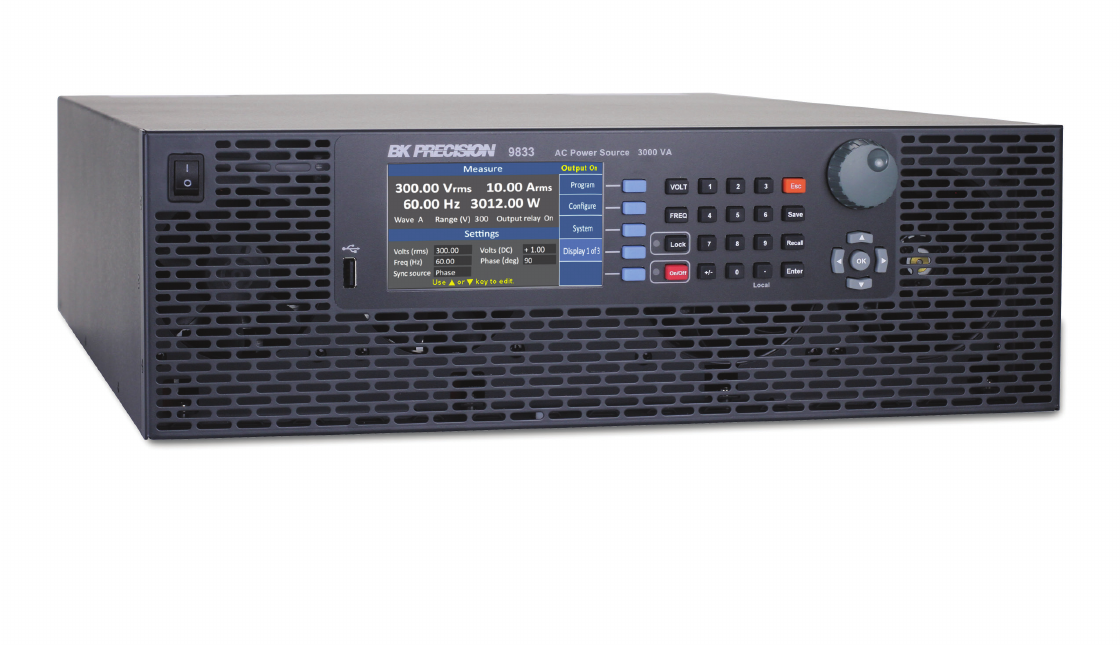
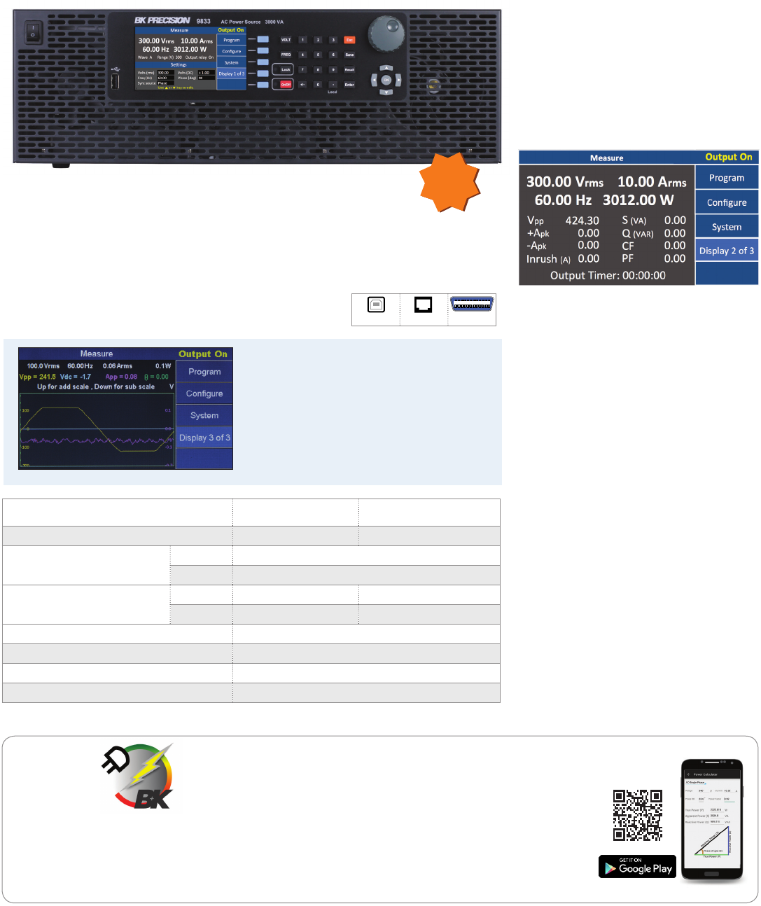
9830 Series Programmable AC Power Source
The 9830 Series are low distortion, single-phase AC power sources delivering a maximum of
3000 VA, 300 Vrms, 30 Arms / 97.5 Apk with the output frequency adjustable from 45 Hz – 1200
Hz. Housed in a compact 3U form factor, the AC source is capable of generating both AC, DC, and
AC+DC output. Measurement display
Features & Benefits
Measurements: Vrms, Arms, Vdc, +Apk,
-Apk, inrush current, frequency, power
factor, apparent power, reactive power,
true power, and crest factor
All measurements can be displayed
simultaneously on a large and bright 4.3”
color LCD
Applications
• Pre-compliance testing according to
IEC61000-3-2
• Evaluating transformers, TRIACs, SCRs,
and passive components
• Simulating common power grid faults
and disturbances
Model 9832 9833
Max power 2000 VA 3000 VA
Max voltage (rms) AC 150 V / 300 V
DC ±212 V / ±424 V
Max current (rms) 0 – 150 V 20 A 30 A
0 – 300 V 10 A 15 A
Frequency range 45 – 1200 Hz
Load regulation ≤ 0.1 % FS (resistive load)
Total harmonic distortion (THD) ≤ 0.5 % at 45 - 400 Hz (resistive load)
Remote interface USB (USBTMC-compliant), GPIB, and LAN
NEW
ElectriKit
Key Features
Calculate DC power and single- or three-phase AC true power,
reactive power, and apparent power
Delta-wye transformation calculator
AWG size calculator to determine wire diameter,
cross-sectional area, and resistance
Voltage drop calculator
Ampacity table for insulated conductors per NEC Table 310.16
A helpful tool for electricians,
technicians, engineers, students,
hobbyists and anyone dealing
with electrical power.
USB (USBTMC) LAN GPIB
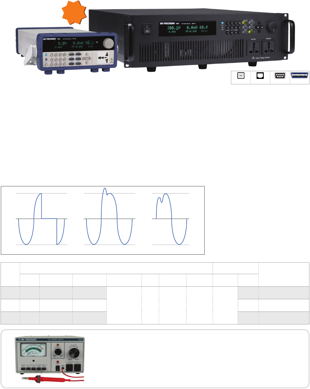
Clipped Sine Wave
Power line disturbance simulation
functions using STEP, LIST, and
Pulse modes
Adjustable phase angle control
Analog input control with a maximum
bandwidth of 1.2 kHz
Save setups and waveform data to USB
flash drive
4 built-in predefined harmonic
distortion waveforms
Generate custom arbitrary waveforms
on a PC then download and execute
waveforms from the power supply 's
internal memory
List mode with 10 user-defined programs
with up to 100 programmable steps each
Digital I/O port for external triggering,
action completed indicator, failure status
indicator, and remote inhibit
Comprehensive protection modes
including OVP, OCP, OTP, fan failure, and
key lock
Power Supplies
Power Meter
20
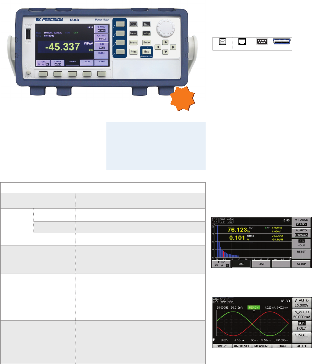
Features & Benefits
4.3-inch color TFT LCD
Simultaneously measure and display up
to 12 AC and DC parameters
Front panel USB host port for data storage
to a USB flash drive
Standard USB (USBTMC), RS232, and
LAN interfaces
Integration function with automatic range
switching for measuring electric energy
External current sensor interface for
measurements above 20 A
Total harmonic distortion (THD) and
harmonic measurements up to the 50th
harmonic with the ability to display
individual harmonic components
Key Specifications
Basic voltage and
current accuracy ±(0.1% of reading + 0.2% of range)
Measurement
range
Voltage 0 - 600 Vrms
Current 0 - 20 Arms
Input bandwidth DC, 0.5 Hz – 100 kHz
Measurements
Voltage, Current, Active power, Reactive power,
Apparent power, Power factor, Phase dierence, Frequency,
V Max/V Min, A Max/A Min, Crest factor, Integration, Harmonic
distortion factor, Total harmonic, distortion (THD)
Voltage and current accuracy
DC: ±(0.1% of reading+0.2% of range)
0.5 Hz ≤ f < 45 Hz: ±(0.1% of reading+0.2% of range)
45 Hz ≤ f < 66 Hz: ±(0.1% of reading+0.2% of range)
66 Hz ≤ f < 1 kHz: ±(0.1% of reading+0.2% of range)
1 kHz ≤ f < 10 kHz: (0.1% of reading+0.2% of range)
±(0.07xf)% of reading+0.3% of range)
10 kHz ≤ f < 100 kHz: ±(0.5% of reading+0.5% of range)
±[{0.04×(f-10)}% of reading]
Active power accuracy
DC: ±(0.1% of reading+0.2% of range)
0.5 Hz ≤ f < 45 Hz: ±(0.3% of reading+0.2% of range)
45 Hz ≤ f < 66 Hz: ±(0.1% of reading+0.1% of range)
66 Hz ≤ f < 1 kHz: ±(0.2% of reading+0.2% of range)
1 kHz ≤ f < 10 kHz: ±(0.1% of reading+0.3% of range)
±[{0.067×(f-1)}% of reading]
10 kHz ≤ f < 100 kHz: ±(0.5% of reading+0.5% of range)
±[{0.09×(f-10)}% of reading]
Applications
Measure power, electric energy bought or
sold back to the power grid, standby power,
and harmonics of motors, uninterruptable
power supplies, battery chargers,
appliances, and consumer electronics.
Harmonic histogram
The parameters of each harmonic measured can be
displayed in a bar chart.
Harmonic measurement
The power meter can display the waveform based
on sampling data for quick analysis of measurement
results.
NEW
5335B Power Meter
The 5335B is a compact, single-phase AC
power meter for measuring and analyzing
energy consumption and power quality up to
600 Vrms, 20 Arms, and bandwidth of 100 kHz.
USB LAN RS232 GPIB
21
www.bkprecision.com
Power Supplies
AC Sources
Model
AC Output AC Input Dimensions
(W x H x D)
Max
power Max current
(rms) Max current
(peak) Total harmonic
distortion Crest
factor Line
regulation Load
regulation Voltage Max
current
9801 300 VA 3 A (0-150 V),
1.5 A (0-300 V) 12 A (0-150 V),
6 A (0-300 V)
≤ 0.5% at
45-400 Hz
(resistive load) ≥ 4 0.1% max
for a ±10%
line change
≤ 0.5% FS
(resistive
load)
110/220
VAC ±10%
30 A 214.5 x 88.2 x 453.5 mm
9803 750 VA 6 A (0-150 V),
3 A (0-300 V) 24 A (0-150 V),
12 A (0-300 V) 15 A 439 × 131.4 × 535.7 mm
9805 1500 VA 12 A (0-150 V),
6 A (0-300 V) 48 A (0-150 V),
24 A (0-300 V) 8 A 439 × 131.4 × 535.7 mm
Power line disturbance (PLD) simulator
The PLD simulator is an extended feature of list mode that provides the user with more control
over the disturbance insertion into the waveform. This can be useful for evaluating a product’s
immunity performance. For instance, a user could produce common waveform disturbances
like surge, sag, spikes, and dropouts at user-defined locations on the waveform.
PLD waveforms
1653A & 1655A AC Power Supplies
The 1653A and 1655A variable isolated AC power
supplies are great for testing AC line voltage
variations or any given product requiring
AC power.
Variable isolated 0 to 150 VAC
2 A (1653A) and 3 A (1655A) continuous output
Features & Benefits
0 to 300 V, low distortion AC power source
with models delivering a maximum of
1500 VA, 12 Arms / 48 A peak
Output frequency adjustable
from 45 Hz – 500 Hz
Select 150 V / 300 V autoranging or 300 V
range operation for continuous sweep
from 0 - 300 V
Displays Vrms, Irms, Ipeak, frequency, PF,
apparent power, true power, and elapsed
output time
Adjustable phase angle control
Programmable voltage and frequency
limit settings
Power line disturbance simulation function
Standard USB, RS232, and LAN interfaces
supporting SCPI commands for
remote control
Standard GPIB interface (9803 & 9805)
Additional features (1655A only)
Built-in soldering iron
temperature control
Expanded leakage scale
Circuit breaker overload protection
9800 Series Programmable AC Power Sources
The 9800 Series is both a programmable AC source and measurement tool. These fully
programmable linear AC sources deliver a maximum of 1500 VA through the universal line
output terminals on the front and the output connector on the rear. The output can be varied
from 0 to 300 V with 0.1 V programming resolution. The output frequency can also be adjusted
from 45 Hz to 500 Hz with start and stop phase angle from 0 to 360 degrees. The bright VFD
display shows Vrms, Irms, Ipeak, frequency, power factor (PF), apparent power, true power, and
elapsed output time.
NEW
USB LAN RS232 GPIB*
* 9803 and 9805 only
22
DC ELECTRONIC LOADS
Unique solutions for DC power testing

23
www.bkprecision.com
DC Electronic Loads
Selection Table
Category Basic Value Performance
Model / Series 8540 8500 8600 SDL MDL
Channel Single Channel Multi Channel
Products in this Category 1 4 6 3 8 6 7 modules
Power Range 150 W 300 - 600 W 1200 - 5000 W 150 - 250 W 750 - 6000 W 4 kW - 8 kW 200 - 600 W(1)
Channels 1 1 1 1 1 1 1 - 16(1)
Settings
CV, CC, CR √√√√√√√
CW √√√√√√
CZ √
Limits
Max Current √√√√√√
Max Voltage √√√√√√
Max Power √√√√√√
Protection
OVP, OCP √√√√√√√
OPP, OTP √√√√√√
Reverse Voltage √√√√√√
Oscillation Detection/Prevention √
Features
List Mode √ √ √√√√√√
Remote Sense √√√√√√
Master / Slave Mode √
Voltage-on (Von) Latch √√√√ √
External Analog Control & Monitor √ √ √ (2) √
Adjustable Slew Rate √ √ √√
Trigger
Manual √√√√√√
Bus √√√√√√
External √√√√√√
Timer √ √ √√
Hold √
Built-in Tests
Short Operation √√√√√√√
Battery Discharge √√√√
CR LED √ √
Remote Interface
USB √√√√√√
RS232 √√√√√√
GPIB √ √ √√
LAN √√
Soware
Front Panel Emulation √√√√√√
NI Certified LabVIEW Drivers √√√√√√
NI Data Dashboard √ √ √√
√ √ Must have rmware version 1.60 or above
(1) Up to 4800 W max power with fully populated MDL001 with MDL002 mainframe extension. Up to 16 channels when using dual input modules
(2) Only the SDL Series oers an analog interface that is isolated
24
DC Electronic Loads
Modular - MDL Series
The MDL Series consists of a mainframe and
seven dierent modules ranging in power
from 200 W to 600 W. Using a modular,
multi-channel design, the electronic load
provides you with the flexibility to test a wide
range of applications from multi-output DC
power supplies to batteries, fuel cells, and
photovoltaics. The mainframe has four slots
and can be configured with any assortment of
the modules up to 2400 W (up to 4800 W with
mainframe extension).
The high-performance electronic load
modules of the MDL Series are capable
of operating in CC (constant current), CV
(constant voltage), CR (constant resistance),
CW (constant power), and CZ (constant
impedance) mode.
For remote communication, the electronic
load provides LAN, USBTMC-compliant USB,
RS232, and GPIB standard interfaces that
support SCPI command protocol.
Features & Benefits
Power range up to 2400 W
Voltage range up to 500 V
Current range up to 120 A
CC, CV, CR, CW, and CZ modes
Adjustable slew rate in CC mode
Removable modules for easy system
configurability
Bright VFD display for both mainframe
and modules
Transient mode up to 25 kHz
List mode up to 100 kHz
Measurement speed up to 50 kHz
101 memory areas to save/recall
setting parameters
Remote sensing
LAN, GPIB, USBTMC-compliant USB,
and RS232 interfaces with SCPI
protocol support
OVP/OCP/OPP/OTP protection
LRV (Local Reverse Voltage) and RRV
(Remote Reverse Voltage) protection
Transient operation enables the module to
periodically switch between two load levels
to test a power supply's regulation and
transient characteristic.
A
T
Slew Rate
High Level
Low Level
List mode lets you generate more complex
sequences of input changes with several
dierent levels.
Transient operation
List mode
Power Input voltage Input current No. of channels CC mode accuracy CV mode accuracy Model
Low range High range Low range High range Low range High range
200 W 80 V 0-4 0-40 1
+(0.05% +
0.05 % F.S.)
+(0.05% +
0.05 % F.S.) +(0.05% +
0.02 % F.S.)
+(0.05% +
0.025 % F.S.)
MDL200
*250 W / 50 W Ch1 80 V/
Ch2 80 V
0-3 A 0-20 A
2
MDL252
*300 W / 300 W 0-4.5 0-45 A +(0.05% +
0.02 % F.S.) MDL302
300 W 500 V 0-3 A 0-20 A
1+(0.05% +
0.025 % F.S.)
MDL305
400 W 80 V 0-6 A 0-60 A MDL400
500 W 500 V 0-3 A 0-30 A MDL505
600 W 80 V 0-12 A 0-120 A +(0.05%+
0.1 % F.S.)
+(0.05%+
0.1 % F.S.) MDL600
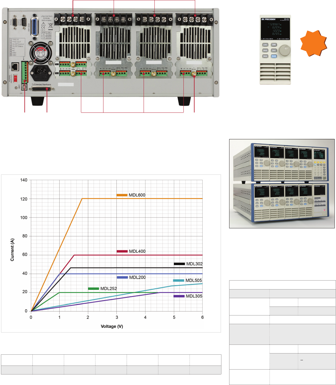
MDL Series Modular Programmable DC Electronic Loads
* The MDL252 and MDL302 are dual-channel modules. MDL252 users can allocate 250 W to either channel up to 300 W total (e.g. 50 W/250 W, 250 W/50 W, 150 W/150 W).
MDL302 users can allocate 300 W to either channel up to 600 W total (e.g. 300 W/300 W).
Adjustable slew rate
In constant current mode, users can control
the rate or slope of the change in current in a
transient response test. Set the slew rate
to as slow as 0.0001 A/µs or as fast as 2.5 A/
µs depending on the module and selected
current range.
25
www.bkprecision.com
DC Electronic Loads
Modular -MDL Series
MDL302 Dual-Channel Module
The MDL302 can support a full 300 W on each
input channel with a voltage and current
operating range up to 80 V/45 A, or 600 W
combined, oering the industry’s highest
power dual-channel DC load module.
Key Specifications
Input voltage 0 – 80 V
Input current Low 0 – 4.5 A
High 0 – 45 A
Input power 300 W (CH1) / 300 W (CH2)
Transient
operation
(CC mode)
Up to 25 kHz
CC mode
(low range)
Resolution 1 mV
Accuracy + (0.05 % +
0.025 % F.S.)
Protection
modes OVP/OCP/OPP/OTP
NEW
Install up to 8 MDL302 modules into the MDL
Series mainframe with extension for a total of
16 x 300 W channels. The load modules can
be used independently or synchronized and
paralleled for increased current and power.
Mainframe
extension
connector
Mainframe
trigger I/O and
synchronization
on/o control
MDL200 MDL252 MDL302 MDL305 MDL400 MDL505 MDL600
1 V 1 V 1.4 V 4.5 V 1.5 V 5.4 V 1.8 V
Low Voltage Operation
The MDL series can operate at low voltages for applications such as fuel cell and
solar cell testing.
Typical minimum operating voltage at full scale current:
Load input terminals
Module remote sense, digital I/O, and analog
current control terminal
Module current
monitoring
terminal
DC Electronic Loads
Stand-Alone Programmable
26
Special Applications
The 8600 Series provides a built-in battery
test mode to measure the ampere-hour
(Ah) characteristic of a battery and a
unique CR-LED mode to simulate the
loading behavior of a typical LED.
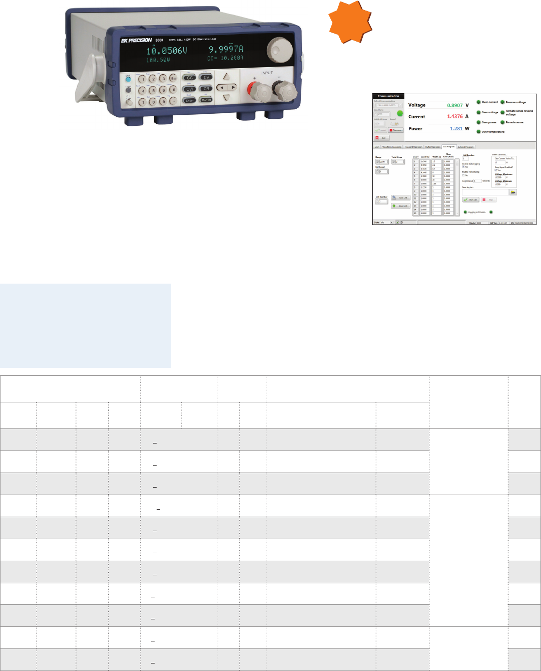
8600 Series Programmable DC Electronic Loads
Features & Benefits
CC/CV/CR/CW operating modes
Measurement speed up to 50 kHz
Remote sense function
Transient mode up to 25 kHz in CC mode
List mode function
Adjustable slew rate in CC mode
Store and recall up to 100 setups
Standard RS232, USBTMC, and GPIB
interfaces supporting SCPI commands for
remote control
Analog current control and monitoring
OVP/OCP/OPP/OTP and reverse
voltage protection
Input ratings CC mode
accuracy
CC mode
resolution
Transient mode
(CC mode) Dimensions Model
Voltage
(High)
Current
(Low)
Current
(High) Power Low High Low High T1 & T2 Accuracy
120 V 3 A 30 A 150 W +(0.05 + 0.05%FS) 0.1
mA
1
mA 20µs - 3600 s / Resolution: 10 µs 5µs + 100 ppm
218 x 90 x 387 mm
(2U half-rack)
8600
120 V 6 A 60 A 250 W +(0.05 + 0.05%FS) 0.1
mA
1
mA 20µs - 3600 s / Resolution: 10 µs 5µs + 100 ppm 8601
500 V 3 A 15 A 200 W +(0.05 + 0.05%FS) 0.1
mA
1
mA 20µs - 3600 s / Resolution: 10 µs 5µs + 100 ppm 8602
120 V 12 A 120 A 750 W +(0.1 + 0.1%FS) 1
mA
10
mA 20µs - 3600 s / Resolution: 10 µs 5µs + 100 ppm
439 x 133.3 x 580 mm
(3U)
8610
500 V 3 A 30 A 750 W +(0.05 + 0.05%FS) 0.1
mA
1
mA 20µs - 3600 s / Resolution: 10 µs 5µs + 100 ppm 8612
120 V 24 A 240 A 1500 W +(0.05 + 0.05%FS) 1
mA
10
mA 20µs - 3600 s / Resolution: 10 µs 5µs + 100 ppm 8614
500 V 6 A 60 A 1200 W +(0.05 + 0.05%FS) 0.1
mA
1
mA 20µs - 3600 s / Resolution: 10 µs 5µs + 100 ppm 8616
120 V 48 A 480 A 3000 W +(0.025 + 0.05%FS) 1
mA
10
mA 20µs - 3600 s / Resolution: 10 µs 5µs + 100 ppm 8620
500 V 10 A 100 A 2500 W +(0.025 + 0.05%FS) 1
mA
10
mA 20µs - 3600 s / Resolution: 10 µs 5µs + 100 ppm 8622
120 V 60 A 600 A 4500 W +(0.025 + 0.05%FS) 1
mA
10
mA 20µs - 3600 s / Resolution: 10 µs 5µs + 100 ppm 439 x 266 x 590 mm
(6U)
8624
120 V 72 A 720 A 6000 W +(0.025 + 0.05%FS) 1
mA
10
mA 20µs - 3600 s / Resolution: 10 µs 5µs + 100 ppm 8625
The 8600 Series programmable DC electronic
loads provide the performance of modular
system DC electronic loads in a compact
benchtop form factor. With fast transient
operation speeds up to 25 kHz, and high
16-bit measurement resolution and accuracy,
these DC loads can be used for testing and
evaluating a variety of DC sources such as DC
power supplies, DC-DC converters, batteries,
battery chargers, and photovoltaic arrays.
Log voltage, current, and power values
with timestamp
Run transient operation and list mode
programs remotely
Create an unlimited number of external
list files to be executed from PC memory
Remote monitoring on iOS, Android
or Windows 8 compatible tablets or
smartphones via NI Data Dashboard for
LabVIEW apps
Application software
NEW
27
www.bkprecision.com
DC Electronic Loads
Stand-Alone Programmable
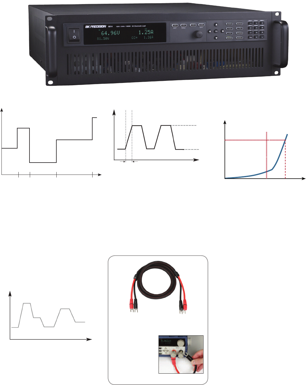
Length: 2 m
Current: 60 A
Gauge: 8 AWG
Material: Flexible
Silicon jacket
High current test lead accessory
Model TLPWR1
Transient operation
Transient operation enables the module to
periodically switch between two load levels.
A power supply's regulation and transient
characteristic can be evaluated by monitoring
the supply's output voltage under varying
combinations of load levels, frequency, duty
cycle, and slew rate. Transient operation can
simulate these conditions.
A
T
Slew Rate
High Level
Low Level
List mode lets you generate more complex
sequences of input changes with several
dierent levels. Up to 7 groups of list files can
be saved. Each list can contain up to 84 steps
with a minimum width time of 20 µs per step.
T
List mode
A
The 8600 Series can execute multiple test
sequences in automatic test mode. Up to
100 dierent sequences can be linked to
run steps of various operating modes and
loading conditions. Each sequence can also
be programmed with upper and lower limit
Pass/Fall criteria. When applied in production
testing, you can easily judge whether the test
parameters of your devices are within the
specification limits and adjust your process
according to the Pass/Fail verdict.
pass
pass
pass
fail
CC 1 A
CW 0.5 W
CV 3 V
CR 2 Ω
1 s 0.5 s 1.5 s 2.5 s
Automatic test mode
Vd = Forward voltage of the LED
Rd = LED's operating resistance
Vo = Operating voltage across the LED
Io = Operating current across the LED
Use the load's unique CR-LED operating mode
to test LED drivers. This function allows users
to configure the LED's operating resistance
and forward voltage along with the voltage
range (same as CR operation) to simulate the
loading behavior of typical LEDs.
CR-LED mode
Figure - LED I-V Curve
R d
Io
I
V d V o V

DC Electronic Loads
Stand-Alone Programmable, High Power Density
28
SDL Series Programmable DC Electronic Loads
The SDL Series high power/high voltage DC
electronic loads oer the industry’s highest
power density (8 kW in 5U form factor)
without sacrificing performance. The DC
electronic loads can operate in constant
current (CC), constant voltage (CV), constant
resistance (CR), and constant power (CW)
mode, and provide arbitrary and pulse
generator capabilities, analog control,
and standard LAN, GPIB, USB, and RS232
interfaces for remote communication.
Features & Benefits
0.05% CC mode readback accuracy
Intelligent PWM fan speed control reduces
unnecessary fan noise and optimizes
heat management
16-bit voltage and current
measurement system
Built in arbitrary and pulse generator for
continuous, pulsed, and toggled
transient operation
Highest power density of 1.6 kW per 1U
rack space
Isolated analog control interface
Flexible ranging options: High and Low,
Manual or Auto
Programmable slew rise and fall time
Fast 50 µs transient time in CC mode and
500 µs in CV mode
Remote inhibit and dry contact
fault output
So-start functionality
Simple closed-case calibration
Master/slave capability to increase
current by paralleling multiple units with
the same voltage rating
Standard LAN, GPIB, USB, and RS232
interface supporting SCPI commands for
remote control
Special applications
The SDL Series oers a wide operating
voltage range up to 1000 V making it ideal for
hybrid, plug-in hybrid, and battery electric
vehicle (HEV/PHEV/BEV) test applications.
Using the built-in arbitrary generator, the
DC loads are suitable for DC power bus
simulation required for immunity testing.
NEW
Specifications 4 kW 8 kW
Models SDL-600-150 SDL-800-75 SDL-1000-25 SDL-600-300 SDL-800-150 SDL-1000-50
Voltage 600 V 800 V 1000 V 600 V 800 V 1000 V
Current 150 A 75 A 25 A 300 A 150 A 50 A
CC Mode
Range Low 0-15 A 0-7.5 A 0-2.5 A 0-30 A 0-15 A 0-5 A
High 0-150 A 0-75 A 0-25 A 0-300 A 0-150 A 0-50 A
Resolution Low 0.9375 mA 0.04688 mA 0.1563 mA 1.875 mA 0.9375 mA 0.3125 mA
High 9.375 mA 4.688 mA 1.563 mA 18.75 mA 9.375 mA 3.125 mA
Programming and readback accuracy 0.05%+0.15 A 0.05%+0.075 A 0.05%+0.025 A 0.05%+0.3 A 0.05%+0.15 A 0.05%+0.05 A
CV Mode
Range Low 0-60 V 0-80 V 0-100 V 0-60 V 0-80 V 0-100 V
High 0-600 V 0-800 V 0-1000 V 0-600 V 0-800 V 0-1000 V
Resolution Low 3.75 mV 5 mV 6.25 mV 3.75 mV 5mV 6.25 mV
High 37.5 mV 50 mV 62.5 mV 37.5 mV 50 mV 62.5 mV
Programming and readback accuracy 0.05%+0.6 V 0.05%+0.8 V 0.05%+1 V 0.05%+0.6 V 0.05%+0.8 V 0.05%+1 V
Transition time Slow 0.5 ms - 511.9 ms
Fast 0.5 ms - 51.19 ms
Form factor 3U 5U
Weight 21 kg 33 kg
Comprehensive protection
Oscillation detection and protection
Undervoltage lockout for battery
discharging and anti-saturation protection
Ability to select system response
bandwidth: Select Fast for maximum
transient response speed or Slow for
maximum stability
Cross mode and cross range function to
turn o input when a switch in operating
mode or range occurs
Pulse power capability with
overpower protection
Built-in hardware protection: overvoltage,
overcurrent, overpower, overtemperature,
reverse voltage, remote sense fault,
unregulated state, and undervoltage
lockout protection
User-defined overcurrent (OCP),
overvoltage (OVP), and
overpower (OPP) protection
29
www.bkprecision.com
DC Electronic Loads
Stand-Alone Programmable /Basic
Features & Benefits
Constant current (CC), resistance (CR),
voltage (CV), and power (CP) operation
Low minimum operating voltage of < 0.1
V and minimum input resistance of 5 mΩ
(model 8518) allow the load to sink high
current at low voltages, required for fuel
and solar cell applications.
Built-in transient generator
Short circuit test
Overcurrent/overvoltage/overpower/
overtemperature protection
RS232 & USB to TTL serial converter cable
and application soware included
List mode operation for
increased throughput
Battery testing mode to provide Ah rating
of battery (cut o voltage level
is adjustable)
Flexible triggering: create trigger events
by front panel keystroke, back panel TTL
signal, or soware
Remote voltage sensing to compensate
for the eect of voltage drop in wires
Features & Benefits
Operates between 0-60 VDC, 1 mA-30 A
(150 W maximum)
Constant voltage (CV), constant
current(CC), and constant resistance
(CR) operation
Very compact and lightweight
Two current ranges: 3 A (1 mA resolution)
and 30 A (10 mA resolution)
Overcurrent and overvoltage protection
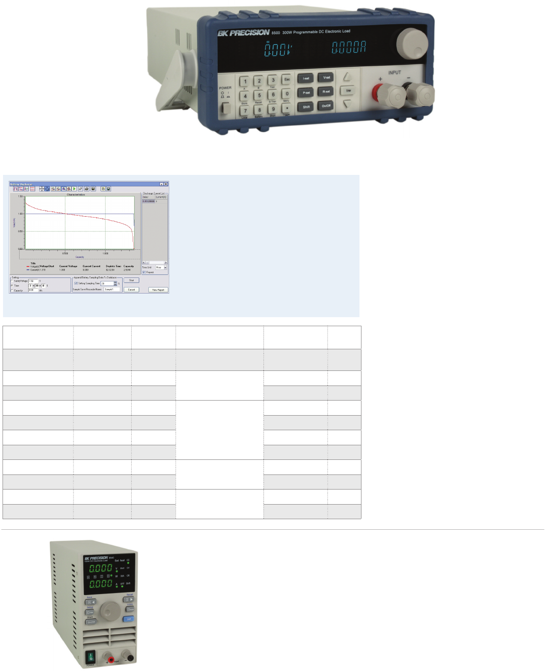
8500 Series Programmable DC Electronic Loads
The 8540 DC electronic load is a compact,
economically priced instrument that can
reliably test a 5 V power supply to 30 A and do
it continuously.
The 8540’s performance is comparable to
most stand-alone bench DC loads, yet it does
the job at half the price and takes up half the
space on your bench.
Operation voltage Rated current Max power Dimensions Weight Model
0.1 V-60 V 30 A 150 W 88 x 175 x 282 mm 2.7 kg 8540
0.1 V-120 V 30 A 300 W 215 x 88 x 355 mm 5.2 kg 8500
0.1 V-500 V 15 A 300 W 5.2 kg 8502
0.1 V-120 V 120 A 600 W
429 x 88 x 355 mm
14 kg 8510
0.1 V-500 V 30 A 600 W 14 kg 8512
0.1 V-120 V 240 A 1200 W 14 kg 8514
0.1 V-60 V 240 A 1200 W 14 kg 8518
0.1 V-120 V 240 A 2400 W 429 x 88 x 355 mm 30 kg 8520
0.1 V-500 V 120 A 2400 W 30 kg 8522
0.1 V-60 V 240 A 5000 W 444 x 357 x 539 mm 67 kg 8524
0.1 V-500 V 120 A 5000 W 67 kg 8526
150 W DC Electronic Load
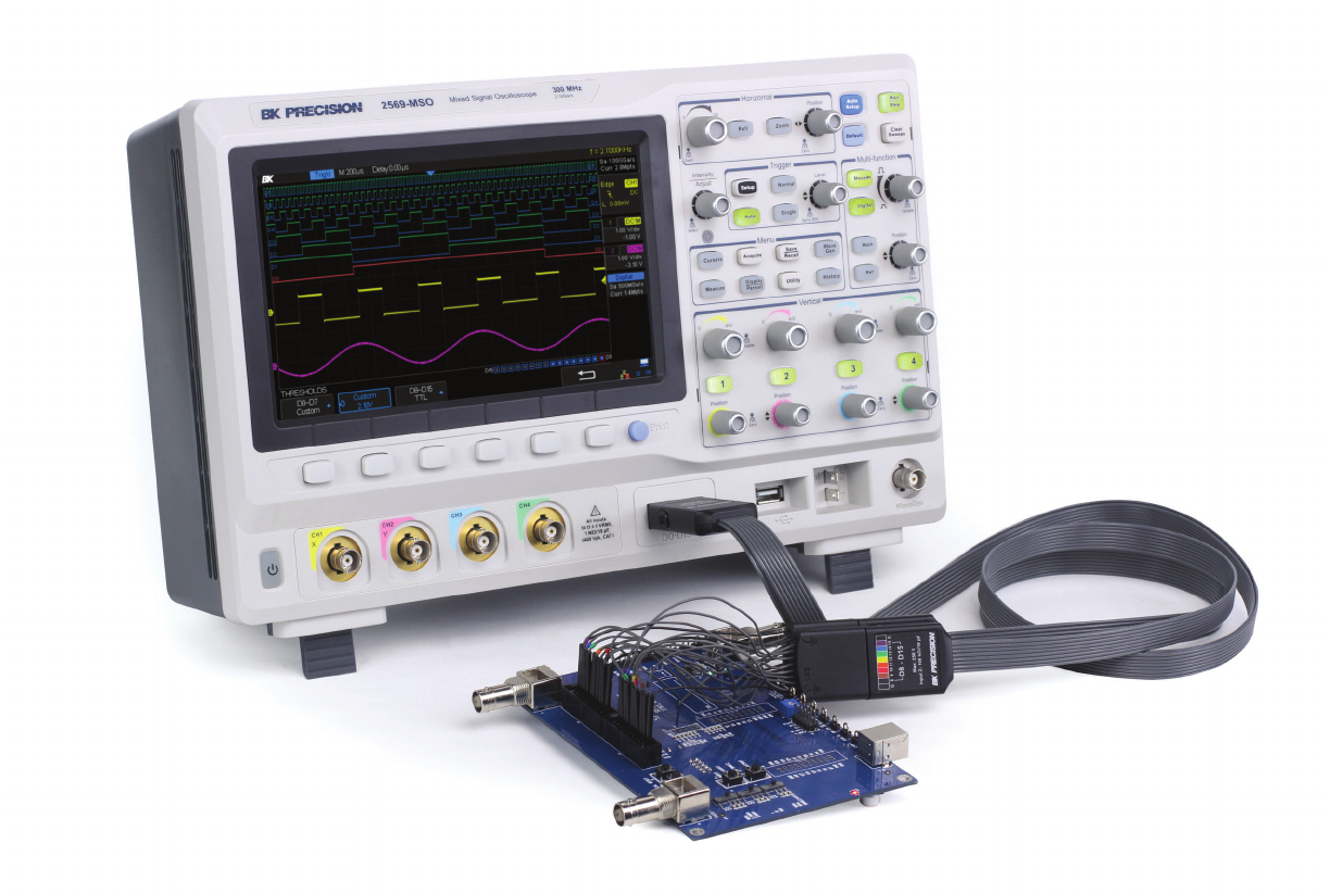
Application software
The included Application Soware supports
front panel emulation of the load and
includes a battery test application which
provides Ah rating of a battery and
adjustable ending voltage levels (safety
voltage).
An example of battery discharge characteristics of
an AA alkaline battery.
OSCILLOSCOPES
Signal analysis made easy
30

www.bkprecision.com
Oscilloscopes
Selection Guide
Digital Storage Oscilloscopes
Bandwidth Sample
rate Channels
Max
memory
depth
PC interface
USB
host
port
Color
display Key features Model Page
100 MHz 1 GSa/s 240 kpts USB device,
LAN √7"
Portable economy oscilloscope
for education and design labs on limited
budgets, special education mode
2190E 37
70 - 200 MHz 1 GSa/s 214 Mpts
USB device,
LAN, GPIB
(optional)
√8" Deep memory up to 14 Mpts, standard
arbitrary waveform generator 2540C Series 34
70 - 300 MHz 2 GSa/s 2 or 4 24 kpts USB device,
LAN √7" High bandwidth and sample rate,
4-channel acquisition (select models) 2550 Series 35
70 - 300 MHz 2 GSa/s 2 or 4 140
Mpts
USB device,
LAN, GPIB
(optional)
√8"
High-performance oscilloscopes with
serial protocol analysis for mixed-signal
and embedded design work (standard
on -MSO models), 16 digital input chan-
nels, high waveform update rate up to
140,000 wfms/s
2560 Series
32
&
33
60 - 100 MHz 1 GSa/s 22 Mpts Mini USB
device √5.7"
Handheld, floating measurement
capabilities, isolated channels for safe
measurements in industrial settings
(models 2515 and 2516)
2510 Series 36
Bandwidth Sweep modes Max sweep rate Delayed dual /
sweep timebase Component tester Counter Model Page
30 MHz Main, X-Y 0.1 µs/div - - - 2120C
37
30 MHz Main, X-Y 0.1 µs/div - - √ 2121C
30 MHz Main, Mix, Delay, X-Y 0.1 µs/div √ √ - 2125C
60 MHz Main, Mix, Delay, X-Y 0.1 µs/div √ √ - 2160C
Analog Oscilloscopes
For users who prefer analog to digital, B&K Precision oers 30 MHz and 60 MHz analog oscilloscopes with simple controls and real-time
waveform display.
31
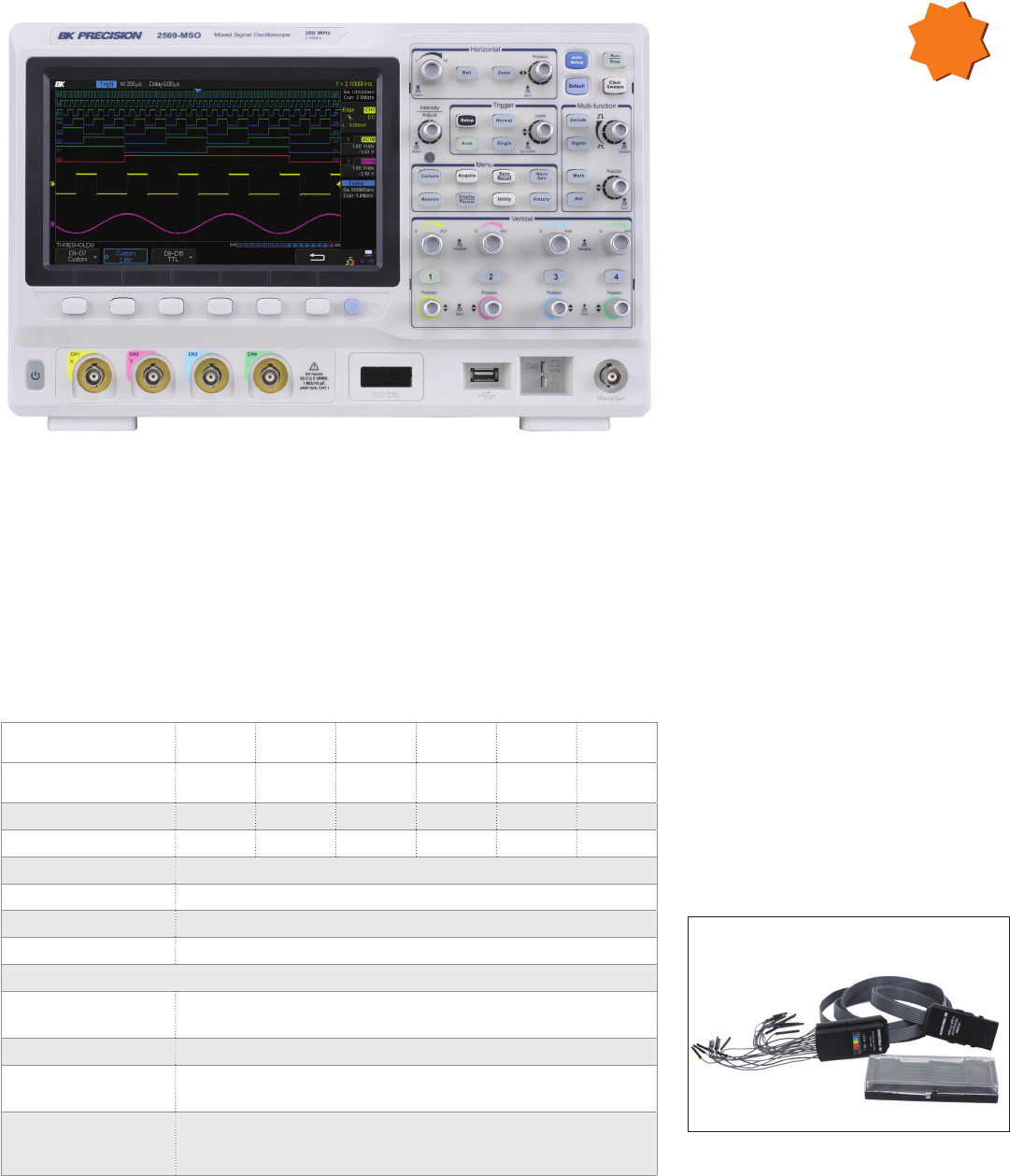
Oscilloscopes
DSO/MSO
2560 Series Digital Storage and Mixed Signal Oscilloscopes
The 2560 Series includes Digital Signal Oscilloscopes (DSO) and Mixed Signal Oscilloscopes
(MSO) from 70 MHz to 300 MHz in 2- and 4-channel configurations. Each model oers 2 GSa/s
sample rate, high waveform update rate up to 140,000 waveforms per second, and a
maximum memory depth of 140 Mpts. In addition, these instruments provide a large 8” color
display with 256 levels of intensity grading, which allow these units to capture and display
more details of a signal for analysis. MSO models include a digital logic probe and
digital soware enabled on the oscilloscope, which provides serial bus triggering and
decoding capabilities for I2C, SPI, UART, RS232, CAN, and LIN protocols.
DSO Model 2563 2565 2566 2567 2568 2569
MSO Model 2563-MSO 2565-MSO 2566-MSO 2567-MSO 2568-MSO 2569-MSO
Bandwidth 70 MHz 100 MHz 200 MHz 200 MHz 300 MHz 300 MHz
Channels 4 4 2 4 2 4
Sample rate 2 GSa/s
Max record length 140 Mpts
Waveform update rate 140,000 wfms/s
PC connectivity Standard LAN (supports SCPI) and USB device port (USBTMC compliant)
Available Upgrades
16-channel
digital logic probe* √
Logic analyzer* √
Serial bus decode
and analysis package** √
25 MHz function/
arbitrary
waveform generator √
Features & Benefits
Bandwidth up to 300 MHz
2 GSa/s sample rate
4-channel acquisition (on select models)
16 digital channels with 500 MSa/s
sampling rate (enabled with MSO option)
Large 8” widescreen display with 256-level
intensity grading and color
temperature display
Waveform capture rate up to 140,000
wfm/s (normal mode), and 500,000 wfm/s
(sequence mode)
Record length up to 140 Mpts
High speed hardware-based pass/fail
testing function
50 Ω input coupling
Segmented acquisition history waveform
record function (record length up to
80,000 frames)
Trigger types: Edge, Slope, Pulse, Video,
Window, Runt, Interval, DropOut, Pattern
Serial bus triggering and decoding
supporting I2C, SPI, UART, RS232, CAN,
and LIN protocols (option)
FFT including seven other math functions:
Addition, Subtraction, Multiplication,
Division, Integration, Dierential, and
Square Root
37 automatic measurements supporting
statistics, gating, math, history, and
reference measurements
Soware provided for remote PC control
Built-in Logic Analyzer (option)
Built-in AWG (option)
*Standard on MSO model. **Supporting I2C, SPI, UART, RS232, CAN, and LIN Protocols.
NEW
16-channel logic probe and logic analyzer function
included with MSO models.
32
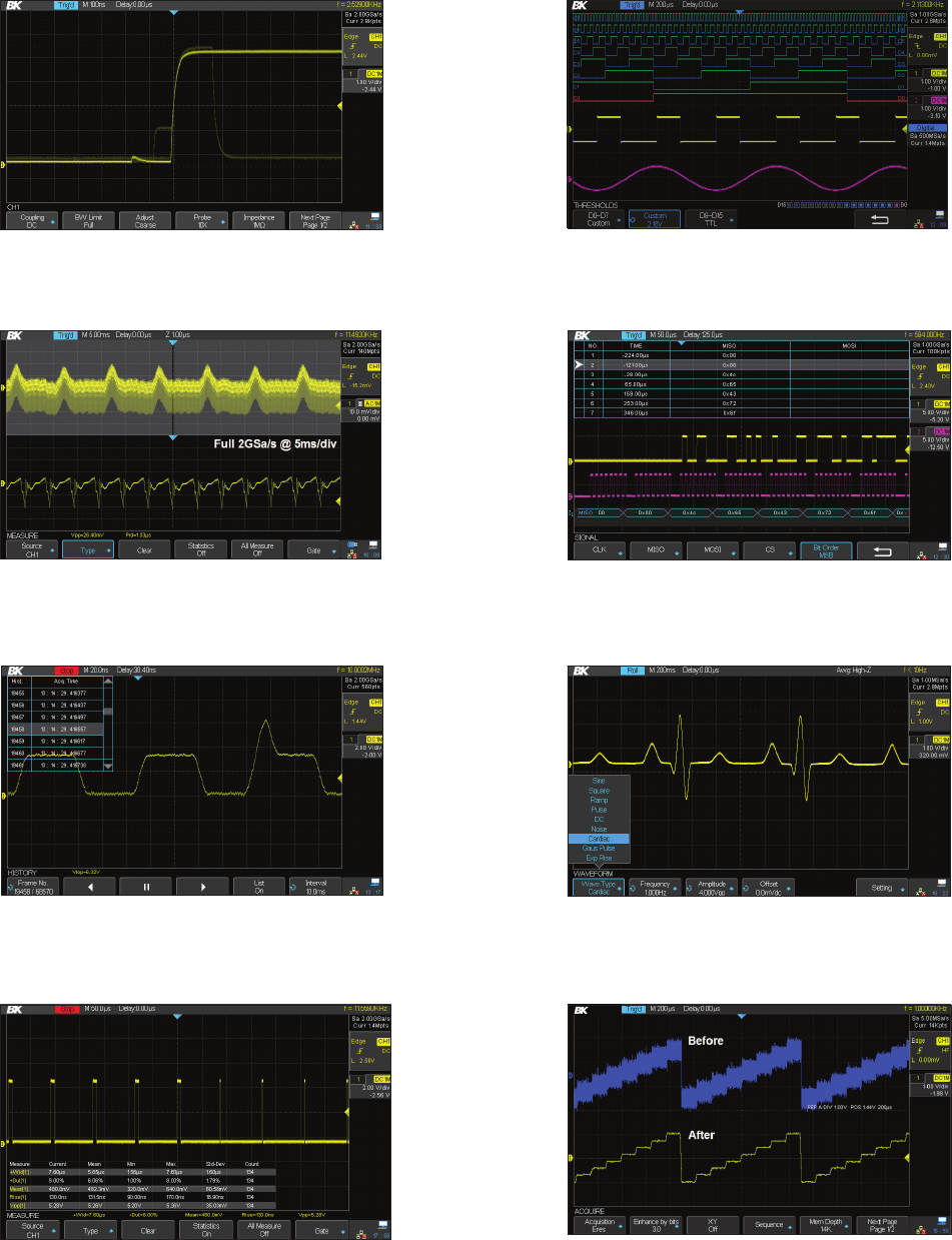
www.bkprecision.com
Oscilloscopes
DSO/MSO
Fast waveform capture rate
The 2560 Series delivers up to 140,000 wfms/s update rate to help you detect
infrequent anomalies and glitches more quickly.
Eres (Enhanced Resolution) mode
Eres mode can improve the SNR eectively, without the dependence on the
periodicity of the signal and stable triggering.
Record length up to 140 Mpts
Using hardware-based Zoom technologies with record lengths of 140 Mpts, users
are able to capture more of their signal with higher sampling rates and quickly
zoom into the event of interest.
History and segmented acquisition (Sequence) mode
Use the instrument’s History and Sequence function to record and play back
waveforms to nd anomalies and quickly locate the source of the problem via
cursor or measurement parameters.
Comprehensive statistical functions
Parametric statistical functions are available for displaying ve parameters of any
measurement: current value, mean value, minimum value, maximum value, and
standard deviation.
Logic analyzer
4 analog channels plus 16 digital channels enable users to acquire and trigger on
the waveforms, and then analyze the pattern simultaneously with one instrument.
Serial bus decoding
Displays the decoding through the events list. Bus protocol information can be
quickly and intuitively displayed in table form.
25 MHz function/arbitrary waveform generator
Take advantage of the generator’s 10 built-in waveforms or generate up to 4 of
your own arbitrary waveforms via waveform editing software.
33
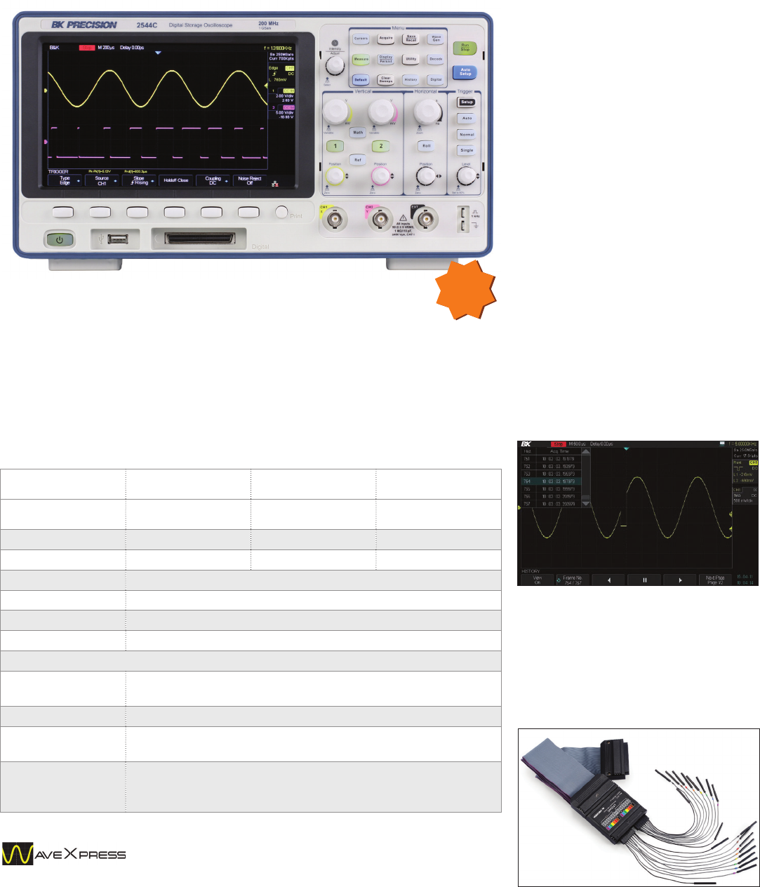
Oscilloscopes
DSO/MSO
2540C Series Digital Storage and Mixed Signal Oscilloscopes
Features & Benefits
Bandwidth up to 200 MHz
Deep waveform memory up to 14 Mpts
25 MHz built-in arbitrary waveform
generator (AWG)
37 automatic measurements
FFT plus three additional math functions
Built-in context sensitive help system
For educators - ability to disable the Auto
set button
PC soware that lets you remotely control
the oscilloscope and capture, save, and
analyze waveform data
Front panel USB port for convenient
storing and recalling of waveform data,
setups, and screenshots on a USB
flash drive
LAN interface enables users to capture
screenshots from any standard
web browser
Seamlessly load waveforms from the
oscilloscope into the WaveXpress
waveform editing soware
History and Segmented Acquisition Mode
Use the instrument’s History and Sequence
function to record and play back waveforms
to find anomalies and quickly locate
the source of the problem via cursor or
measurement parameters.
The B&K Precision 2540C Series dual channel digital storage oscilloscopes deliver performance
and value, all in one portable solution. Maximize productivity using extensive features such as
digital filtering, waveform recorder, pass/fail limit testing, and automatic measurements. These
oscilloscopes oer powerful tools in a small aordable package with bandwidth up to 200 MHz,
1 GSa/s sample rate, and deep memory up to 14 Mpts. All models come standard with a built-in
25 MHz function/arbitrary waveform generator.
DSO Model 2540C 2542C 2544C
MSO Model 2540C-MSO 2542C-MSO 2544C-MSO
Bandwidth 70 MHz 100 MHz 200 MHz
Channels 222
Sample rate 1 GSa/s
Max record length 14 Mpts
Waveform update rate 60,000 wfms/s
PC connectivity Standard LAN (supports SCPI) and USB device port (USBTMC compliant)
Available Upgrades
16-channel
digital logic probe* √
Logic analyzer* √
Serial bus decode
and analysis package** √
25 MHz function/
arbitrary
waveform generator Standard
NEW
*Standard on MSO model. **Supporting I2C, SPI, UART, RS232, CAN, and LIN Protocols.
16-channel logic probe and logic analyzer function
included with MSO models.
34
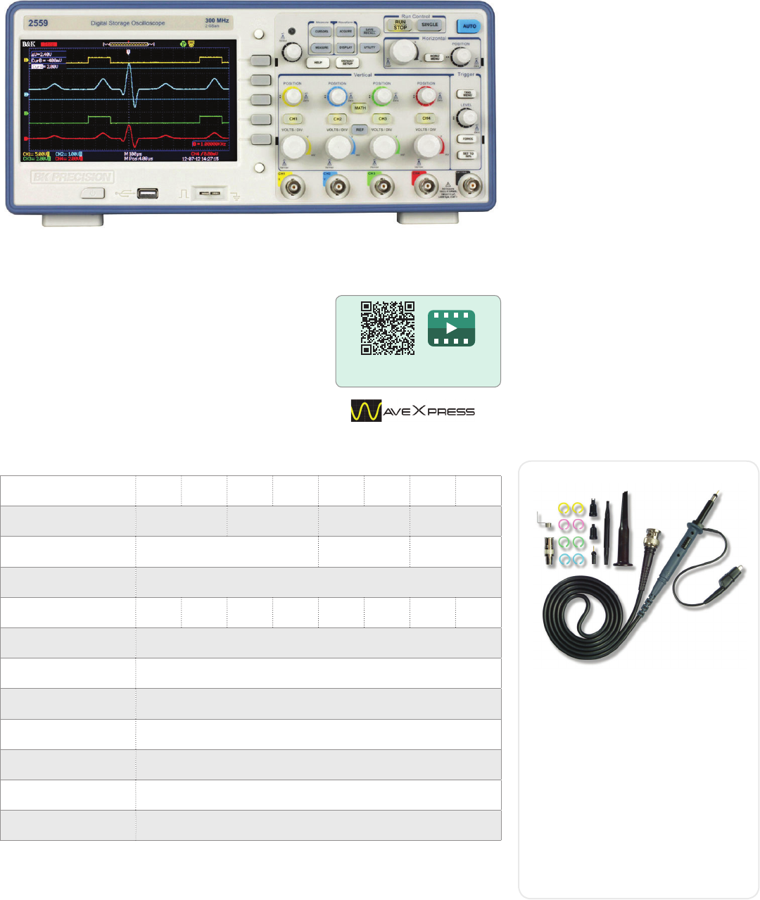
www.bkprecision.com
Oscilloscopes
DSO
The 2550 Series Digital Storage Oscilloscopes provide
high performance and value in 2-channel and 4-channel
configurations. With bandwidths from 70 MHz to 300 MHz
and 2 GSa/s sample rates, these oscilloscopes oer 24
kpts/Ch waveform memory, 32 automatic measurements,
advanced triggering capabilities, math function, PC
connectivity via LAN and USB. The 2550 is engineered for
best visibility. The 7" TFT display oers a significantly larger
viewing area than typical economy oscilloscopes (5.7").
2550 Series Digital Storage Oscilloscopes
Features & Benefits
Bandwidth up to 300 MHz
2 GSa/s sample rate
4-Channel acquisition (on select models)
Large 7" widescreen color display
FFT including four additional math
functions: Add, Subtract, Multiply,
and Divide
32 automatic measurements
USB host port for remote PC control
Front panel USB device port for saving
and recalling waveform setups, data, and
screenshots on a USB flash drive
50 Ω input coupling
PC control through EasyScope soware
Advance tools include digital filters with
adjustable limits, pass/fail testing and
waveform recorder mode
Multi language user interface and context
sensitive help
Seamlessly load waveforms from the
oscilloscope to WaveXpress waveform
editing soware and send them to
arbitrary waveform generators
Scan QR code to watch
2550 Series overview video
Specifications 2552 2553 2554 2555 2556 2557 2558 2559
Bandwidth 70 MHz 100 MHz 200 MHz 300 MHz
Included probes PR150 (150 MHz) PR250 (250 MHz) PR500 (500 MHz)
Real time sample rate 2 GSa/s (interleaved), 1 GSa/s (per channel)
Channels 24242424
Display 7” widescreen Color LCD
Memory depth 24 kpts max. (interleaved, single CH operation), 12 kpts (each channel)
I/O Interface USB host port, USB device port, LAN
Vertical resolution 8 bits
Vertical sensitivity 2 mV – 5 V/div
Weight 4.3 kg
Dimensions (W x H x D) 336 x 118 x 152 mm
Avoid limiting the bandwidth of your
measurement system. All 2550 series
models come standard with high
bandwidth, slimline passive probes (one
per channel) to help you get the most out
of your scope
Features
Snap-locking sprung hook
Easily replaceable tip
Large accessory set
Meets IEC 61010-031 CATII
RoHS compliant
High bandwidth passive oscilloscope probes
PR150B/250B/500B
35
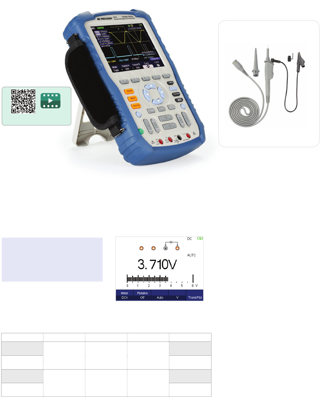
Oscilloscopes
Handheld
2510 Series Handheld Digital Storage Oscilloscopes
The 2510 Series handheld digital storage oscilloscopes provide floating measurement
and recorder capabilities with a built-in digital multimeter (DMM), all in one portable and
lightweight package. These versatile 60 MHz and 100 MHz bandwidth scopes oer 1 GSa/s
sample rates, 2 Mpts waveform memory, 32 automatic measurements, and multiple recording
functions to capture transient or long-term signal behavior.
Features & Benefits
60 MHz (2511/2515) and 100 MHz
(2512/2516) bandwidth
1 GSa/s sample rate
Deep waveform memory up to 2 Mpts
Built-in 6000-count DMM with dedicated
terminals for current measurement
Scope and meter trend plot functions for
data logging
Bright 5.7” color display
Compact and lightweight – 1.54 kg
FFT including four additional math
functions: Add, Subtract, Multiply,
and Divide
32 automatic measurements
USB host port for saving and recalling
waveform setups, data, and screenshots
on a USB flash drive
Soware provided for remote PC control
Multi-language user interface
Up to four hours of continuous
battery operation
Advanced tools include digital filters with
adjustable limits, scope and waveform
recorder mode. The scope recorder
function oers users 7 Mpts record length
on a single channel or 3.5 Mpts on dual
channels.
Safety rated high bandwidth
oscilloscope probes included
Probe Model PR250SA for 2515/2516
Scan QR code to watch
2510 Series overview video
Applications
The 2510 Series handheld oscilloscopes
are ideal for industrial applications, power
systems, electronics design, and field test
and service.
Speed up troubleshooting with the built-in
6000-count multimeter. Measurement functions
include AC/DC voltage and current, resistance,
capacitance, diode, and tcontinuity test.
Built-in Digital Multimeter
Bandwidth Channels CAT rating Typical applications Model
60 MHz
2 non-isolated 300 V CAT II General
electronics
2511
100 MHz 2512
60 MHz
2 fully isolated 1,000 V CAT II,
600 V CAT III Power electronics
and industrial
2515
100 MHz 2516
36
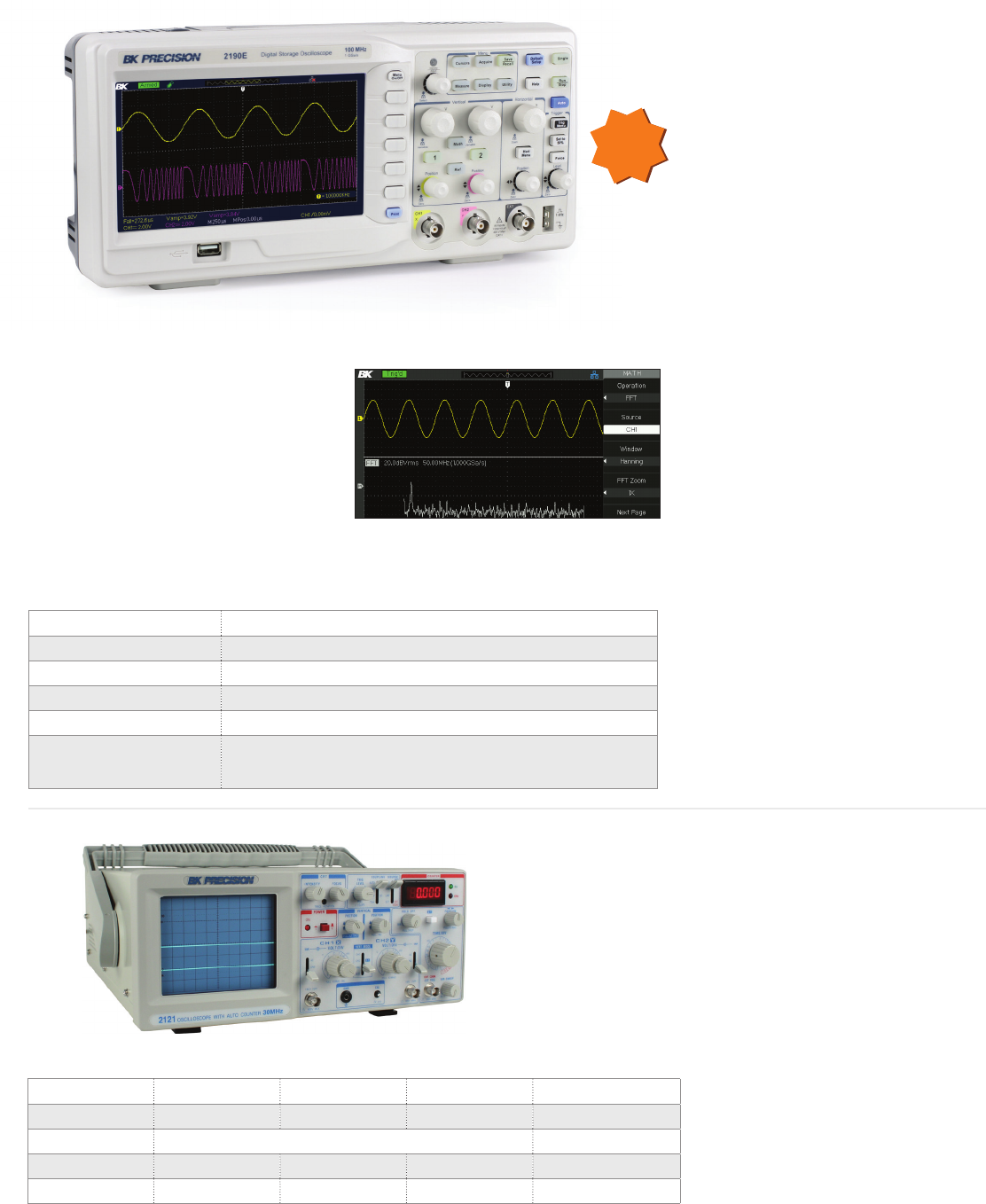
www.bkprecision.com
Oscilloscopes
Economy & Analog
Features & Benefits
100 MHz bandwidth, 1 GSa/s sample rate
Large, 7” widescreen color display oers
a significantly larger viewing area than
typical economy oscilloscopes (5.7”)
32 automatic measurements
FFT plus four additional math functions
Versatile triggering capabilities including
pulse width, line-selectable video, slope,
and alternating trigger
Advanced tools include digital filter with
adjustable limits, pass/fail testing, and
waveform recorder mode
12 dierent language user interfaces and
context sensitive help
Special EDU mode allows educators to
disable Auto set button, Measure menu,
and Cursors menu
PC soware that lets you remotely control
the digital storage oscilloscope and
capture, save, and analyze waveform data
Front panel USB host port for saving and
recalling waveform setups, data, and
screen shots from the oscilloscope onto a
USB flash drive
LAN and USBTMC compliant USB device
port supporting SCPI commands for
remote PC control
The 2190E oscilloscope combines
performance and value all in one portable
solution. With a large, high-resolution
display, standard LAN and USBTMC-
compatible USB interface, advanced
triggering capabilities, and extensive features
such as digital filtering, waveform
recorder and 32 automatic measurements,
this oscilloscope oers powerful tools in a
small aordable package.
2190E 100 MHz, 1 GSa/s, 2-Ch Digital Storage Oscilloscope
Specifications 2190E
Bandwidth 100 MHz
Sample Rate 1 GSa/s
Memory 40 kpts
Display 7” widescreen color LCD with 800 x 480 resolution
I/O Front panel USB host port supporting USB flash drives and optional
USB-to-GPIB adapter, LAN, and USB (USBTMC-compliant) device port
for connection to PC, Pass/Fail output
B&K Precision's 212x Series are dual trace oscilloscopes that oer
high performance at a low price. Most competitors' entry level
oscilloscopes have a 20 MHz bandwidth, while B&K Precision's
212x Series have a bandwidth of 30-60 MHz.
Common Features & Benefits
Dual or single trace operation
5 mV/div sensitivity
Calibrated 23-step time base with
X10 magnifier
Video sync trigger
Alternate/chop sweep
Sum and dierence capability
Specifications 2120C 2121C 2125C 2160C
Bandwidth 30 MHz 30 MHz 30 MHz 60 MHz
Sweep Time 0.1 µs/div - 2 s/div 20 ns/div - 5 s/div
Component Tester - - √ √
Counter - √ - -
Analog Oscilloscopes
B&K Precision oers a wide selection of analog oscilloscopes.
From entry-level to high performance, these oscilloscopes provide
many features at a low cost.
Powerful measurement functions
Display and measure the input signal's frequency
spectrum. Select one of the 4 FFT windows:
Rectangular, Hanning, Hamming and Blackman.
Use cursors to measure the spectral component's
magnitude and frequency.
NEW
37

COMPONENT TESTERS
Troubleshoot with confidence
38
Component Testers
Selection Guide
B&K Precision oers a wide range of component testers that can measure and identify values of capacitors, resistors, inductors, diodes, ICs, and
transistors. Major applications are component sorting or circuit troubleshooting.
LCR Meters are versatile instruments as they can measure most common passive components used in electronic circuitry. Capacitance meters
on the other hand are dedicated to testing capacitors only, and typically oer a wider capacitance measurement range. Our transistor testers
and ESR meters can be invaluable tools when testing and troubleshooting components “in-circuit”, while logic probes are always used in-circuit.
IC Testers are used to identify and test certain analog and digital ICs.
Category Description Max range Basic accuracy Model Page
LCR, bench
500 kHz LCR Meter 150 kH / 150 mF / 100 MΩ 0.05% 894 40
1 MHz LCR Meter 150 kH / 150 mF / 100 MΩ 0.05% 895 40
300 kHz LCR Meter 150 kH / 80 mF / 20 MΩ 0.1% 891 41
200 kHz LCR Meter 31.83 kH / 15.91 mF / 20 MΩ 0.1% 889B 41
LCR, handheld
LCR Meter 200 H / 20 mF / 20 MΩ 1% 875B 42
1 kHz LCR Meter 1 kH / 20 mF / 10 MΩ 0.5% 878B 42
10 kHz LCR Meter 1 kH / 20 mF / 10 MΩ 0.5% 879B 42
10 kHz LCR Meter 31.83 kH / 15.91 mF / 20 MΩ 0.2% 885 42
100 kHz LCR Meter 1 kH / 20 mF / 10 MΩ 0.1% 880 42
100 kHz LCR Meter 31.83 kH / 15.91 mF / 20 MΩ 0.2% 886 42
Capacitance
Compact Capacitance Meter 20 mF 0.5% 810C 43
Dual Display Capacitance Meter 50 mF 0.5% 890C 43
Dual Display Capacitance Meter 200 mF 0.5% 830C 43
Component tester Component Tester 20 mF/ 20 MΩ 0.5% 815 43
IC Linear IC Tester --- --- 570A 43
Digital IC Tester --- --- 575A 43
ESR In-Circuit ESR Tester 2200 µF --- 881 43
Logic probes
Digital Logic Probe 20 MHz --- DP 21 43
Digital Logic Probe 50 MHz --- DP 52 43
Logic Pulser Probe 400 Hz --- DP 31A 43
DC resistance
meter
DC resistance meter 20 kΩ 0.05% 2840 44
DC resistance meter 100 MΩ 0.01% 2841 44
Introduction to the benefits of LCR meters and the theory behind the
measurements, plus related terms and example applications.
For more guides and applications, visit: bkprecision.com/product-applications
LCR Meter Guide
39
www.bkprecision.com
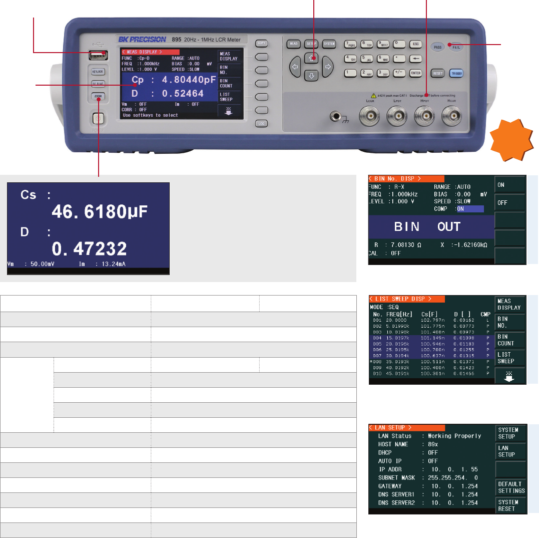
Component Testers
Bench LCR
894 & 895 Performance LCR Meters
The 894 and 895 are high accuracy and high precision bench LCR meters capable of measuring inductance, capacitance, and resistance with
a basic accuracy of 0.05% over a frequency of up to 1 MHz. These meters feature a vivid 4.3-inch TFT LCD with five convenient display modes,
auto level control (ALC), cable length compensation (1/2/4 m), and bin sorting comparator. For accurate measurements, these performance LCR
meters provide Open, Short, and Load corrections.
Use the built-in sweep function to conveniently
display, analyze and store primary and secondary
parameters of a component at up to 201 frequencies.
Zoom display mode
With a touch of a button, users can enlarge
the display for easy viewing from a distance.
The voltage and current across the DUT are
also monitored in this display mode.
Use the BIN comparator function to sort components
in up to 10 bin locations.
Integrate your LCR meter into an automated test
system and control it from a PC using SCPI commands
via the RS232, USB, LAN, or GPIB interface.
Model 895
USB host port
Connect your USB flash drive to
conveniently save data logs, settings,
and screenshots.
Variable test signals
The instrument provides settable voltage
levels from 5 mVrms to 2 Vrms to evaluate
your DUT.
Intuitive user interface
Easily change test parameters using
the menu-driven front panel keypad.
4.3" TFT
color
display
Pass/Fail
LED
indicators
Model 894 895
Measurement parameters L, C, R, G, X, Z, Y, B, G, θ, Q, D, DCR
Basic accuracy 0.05%
DCR measurement range 0.01 Ω - 100 MΩ
Test signal
Frequency range 20 Hz - 500 kHz 20 Hz - 1 MHz
Frequency accuracy 0.01%
AC level range 5 mVrms - 2 Vrms / 50 µArms - 20 mArms (adjustable)
DC bias 0 V - +5V / 0 mA - +25 mA
Output impedance 30 Ω, 50 Ω, or 100 Ω
Selectable measurement speeds 13 ms (Fast), 90 ms (Med), 370 ms (Slow)
Auto level control (ALC) √
Cable length compensation √
Handler interface √
Remote interface RS232, USB (USBTMC), LAN, and GPIB (895 Only)
Dimensions 369 x 108 x 408 mm
Weight 5 kg
NEW
BIN comparatorList sweep
Remote PC control
40
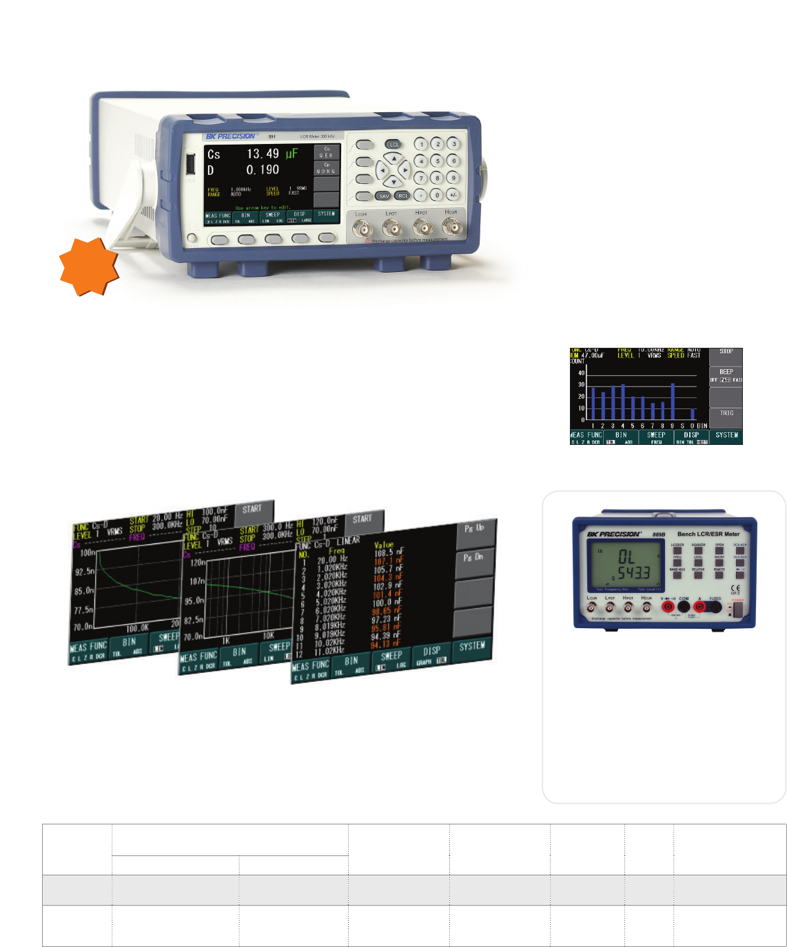
Component Testers
Bench LCR
Specifications Test signal Inductance
measurable
range
Capacitance
measurable
range
Resistance
measurable
range
Weight Dimensions
(W x H x D)
Frequency Level
891 20 Hz - 300 kHz 0.5 Vrms & 1 Vrms
selectable 0.05 uH - 150 kH 0.06 pF - 80 mF 0.1 Ω - 20 MΩ 3.4 kg 258 × 113 × 381 mm
889B 100 Hz, 120 Hz, 1 kHz,
10 kHz, 100 kHz, 200 kHz
1 Vrms, 0.25 Vrms,
50 mVrms,
1 VDC (DCR only 0.079 uH - 31.83 kH 0.079 pF - 15.91 mF 0.1 Ω - 20 MΩ 4.5 kg 220 x 300 x 150 mm
Features (model 891)
Measurement parameters: L, C, R, Z, G, B,
Y, D, Q, θ, DCR
0.05% best impedance accuracy
Fully adjustable test frequency from 20 Hz
to 300 kHz with 4-digit resolution
Adjustable measurement speed for
fasreadout or better accuracy
Save/recall up to 100 setups
(10 internal) including 1000
measurements and screenshots
Standard USB (Virtual COM), GPIB, and
LAN interface for remote control
BIN sorting function
891 300 kHz Bench LCR Meter
The 891 is a compact, precise, and versatile LCR meter capable of measuring inductors,
capacitors, and resistors at DC or from 20 Hz to 300 kHz, at both low and high impedance
ranges. A large color display with all important parameters and measurements visible on one
screen makes this meter easy to operate. A standard USB, GPIB and LAN interface enhances
your productivity. The outstanding performance of the 891 makes it an invaluable tool in
production, quality control and R&D.
Linear and logarithmic sweep function
Characterize components up to 300 kHz using a 300-point linear or logarithmic sweep.
Measured values for each frequency point can be read directly on the display. Sweep results
can be displayed on a graph or table and then saved to a USB flash drive or read out through
the remote interface.
NEW
Features & Benefits
Measurement parameters: ACV, DCV, Z,L,
C, DCR, ESR, D, Q, and Ø
Diode and continuity measurements
Measures DCV to 600 V and ACV to
600 Vrms at 40 Hz to 1 kHz
Virtual COM USB interface
889B 200 kHz Bench LCR Meter
Quickly sort components with 9 primary
BINs, 1 secondary BIN, and 1 out BIN
41
www.bkprecision.com
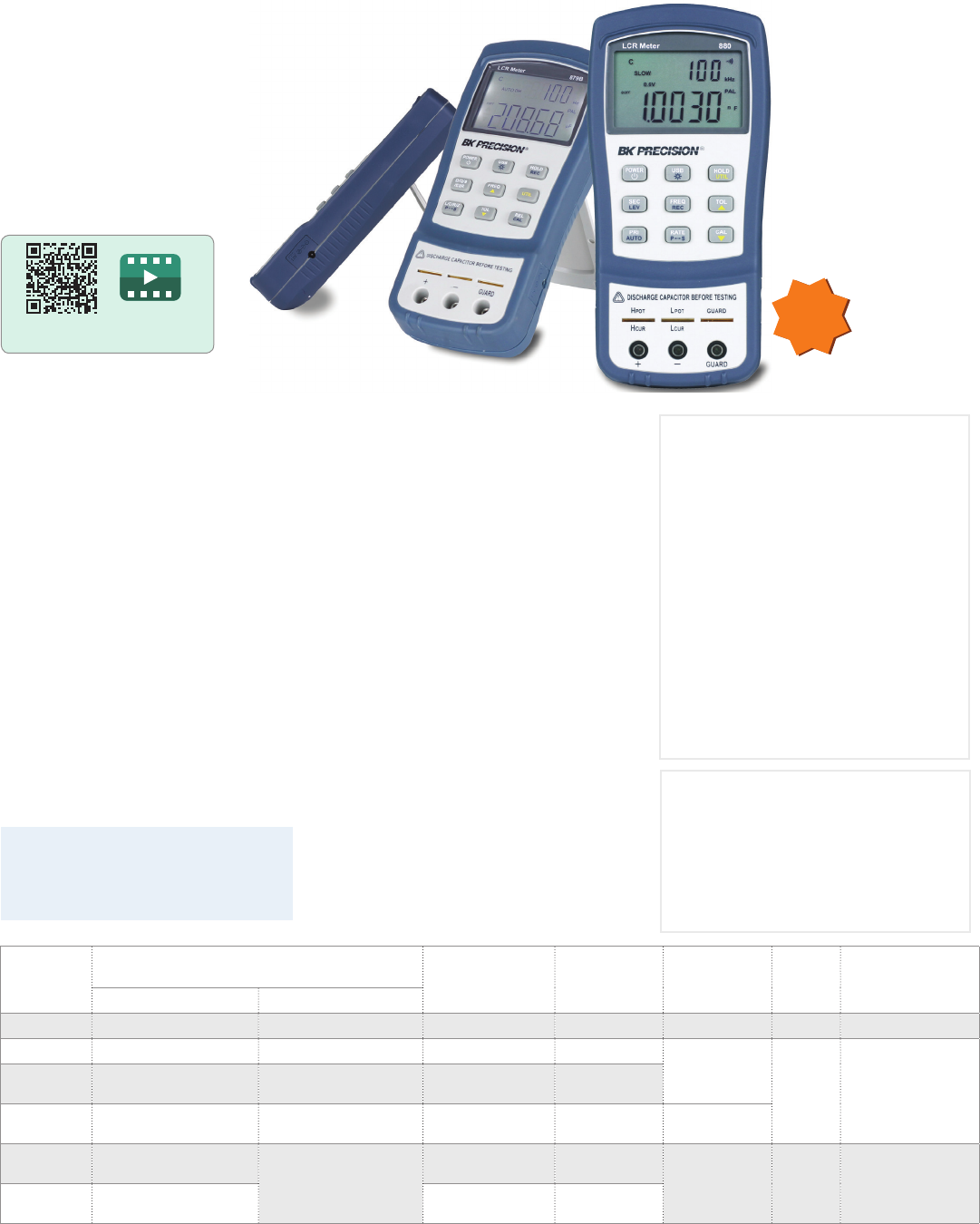
Component Testers
Handheld LCR
Specifications Test signal Inductance
measurable
range
Capacitance
measurable
range
Resistance
measurable
range
Weight Dimensions
(W x H x D)
Frequency Level
875B 120 Hz, 1 kHz Approximately 0.5 Vrms 20 uH - 200 H 20 pF - 20 mF 0.2 Ω - 20 MΩ 400 g 88 x 177 x 40 mm
878B 120 Hz, 1 kHz Approximately 0.6 Vrms 40 uH - 1000 H 40 pF -20 mF
0.04 Ω - 10 MΩ
330 g 90 x 190 x 41 mm
879B 100 Hz, 120 Hz, 1 kHz.
10 kHz Approximately 0.6 Vrms 4 uH - 1000 H 4 pF -20 mF
880 100 Hz, 120 Hz, 1 kHz.
10 kHz, 100 kHz 0.3 Vrms, 0.6 Vrms,
1 Vrms, 1 VDC 0.4 uH - 1000 H 0.4 pF -20 mF 0.04 Ω - 10 MΩ
885 100 Hz, 120 Hz, 1 kHz,
10 kHz 1 Vrms, 0.25 Vrms,
50 mVrms,
1 VDC (DCR only)
1.592 uH - 31.83 kH 0.795 pF -
15.92 mF 0.1 Ω - 20 MΩ 470 g 86 x 175 x48 mm
886 100 Hz, 120 Hz, 1 kHz,
10 kHz, 100 kHz 0.159 uH - 31.83 kH 0.795 pF -
15.92 mF
Features & Benefits
40,000 counts resolution on primary
and 10,000 counts resolution on
secondary display
L, C, R, and Z (879B & 880 only) primary
measurements
Automatic calculation of secondary
parameters D, Q, θ, ESR (θ/ESR for 879B &
880 only), and DCR (880 only)
Accuracy up to 0.1% and selectable test
frequencies up to 100 kHz (880 only)
Fast auto range design for rapid, easy
component measurements
Auto detect mode for automatic
component type identification and
measurement type selection (880 only)
Backlit display (879B & 880 only)
Data Hold and Min/Max/Average recording
USB (Virtual COM) interface
SCPI compliant commands for remote
communication
The 878B, 879B, and 880 40,000-count
handheld LCR meters measure inductance,
capacitance, and resistance quickly and
precisely. The 879B and 880 also measures
impedance, θ, DCR, and ESR.
Additionally, the 880 oers capabilities
typically only found in bench LCR meters
such as a 4-terminal configuration, basic
measurement accuracy up to 0.1%, test
frequencies up to 100 kHz, selectable test
signal levels, and measurement rate.
Fast auto ranging and quick measurement
configuration such as measurement
parameter and test frequency selection make
these meters very simple to operate.
Features & Benefits
Measurement parameters: Z, L, C, DCR,
ESR, D, Q, and Ø
Test conditions: 100 Hz, 120 Hz, 1 kHz,
10 kHz, 100 kHz (model 886), 1 Vrms,
0.25 Vrms, 0.05 Vrms
0.2% basic accuracy
Dual LCD display
SMD surface mount tweezer
probe included
Features & Benefits
Measures D (dissipation factor)
Zero adjustment knob
NEW
Scan QR code to watch
How to use an LCR meter video
Model 875B is a manual range, hand-held
20,000 count LCR meter that is reliable and
easy to use.
Models 885 & 886 are 10,000-count
handheld meters equipped with 4-wire
terminal connections to facilitate more
accurate measurements.
878B, 879B and 880 40,000-count Dual Display LCR Meters
Applications
• Passive components trouble shooting
• Quality control (component sorting)
42
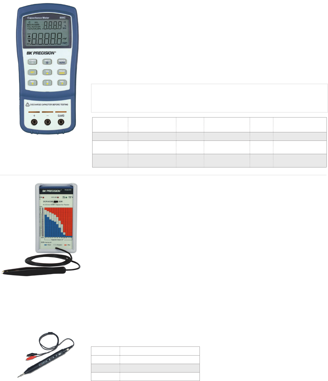
Component Testers
Handheld Capacitance, IC, ESR, Logic
The 810C is a compact manual ranging capacitance meter, designed for accurate, cost-eective
measurements of capacitive components. It features fused direct-plug-in test sockets, test lead jacks,
and a zero adjustment knob to "zero" test lead capacitance.
The 830C and 890C are 11,000-count handheld
capacitance meters that measure capacitance up to
200 mF and 50 mF respectively. Straightforward to
operate, these meters make measurements quickly
and simplify the capacitance sorting process. Unlike
other handheld instruments such as LCR meters that
make measurements using an AC signal with a specific
test frequency, these meters measure capacitance by
applying a constant current that briefly charges, then
discharges the connected capacitor.
Features & Benefits
0.5% basic accuracy
Measure capacitance up to 200 mF
(50 mF for 890C) right LCD backlight
Fast auto ranging design for rapid, easy
component measurements
USB (Virtual COM) interface
SCPI compliant commands for
remote communication
Soware for data logging and front panel
emulation available as free download
830C & 890C Dual Display Handheld Capacitance Meters
Specifications Special
Features Test Level Measurable Range Weight Dimensions
(W x H x D)
810C Manual range dial <3.5 V 20 pF - 20 mF 200 g 70 x 151 x 38 mm
890C Sorting function,
tolerance function <3 V 100 pF - 50 mF 350 g 190 x 90 x 41 mm
830C Sorting function,
tolerance function <3 V 100 pF - 200 mF 350 g 190 x 90 x 41 mm
570A & 575A IC Testers
The 570A interfaces with analog ICs and the 575A
with digital ICs. Both versions emulate passive
circuitry around the IC under test to ensure that
a comprehensive test takes place. The units
automatically sense the functionality of the
device to be tested and display a list of possible
equivalents for replacement.
The 881 is a portable In-Circuit ESR Meter that
measures the equivalent series resistance of
electrolytic capacitors in or out of circuit and can also
be used to measure low value non-inductive resistors.
In-circuit measurements are dependent on the circuit
design of the capacitor being measured.
Features & Benefits
Measures ESR with a range of 0.1 to 30 Ω
Measures DCR with a range of 0.1 to 30 Ω
15 mVp-p output test voltage (will not turn
on any solid-state devices)
Includes a one-handed tweezer test probe
Model 890C
Model 881
Model DP 21
815 Component Tester
The 815 is a handy meter measuring capacitance
up to 20 mF and resistance up to 20 MΩ and can
also test transistors, diodes, SCRs, LEDs,
and batteries.
Logic Probes
For use with TTL and CMOS circuits and ICs
Model Description
DP 21 20 MHz Digital Logic Probe
DP 52 50 MHz Digital Pulser Probe
DP 31A 400 Hz Digital Pulser Probe
Features & Benefits
Transistor leakage test
Diode and SCR test
LED test
Battery test
881 In-Circuit ESR & DCR Capacitor Tester
Features & Benefits
Auto identification mode
Conditional/unconditional loop
testing mode
Displays diagnostic information down to
individual component pins
43
www.bkprecision.com
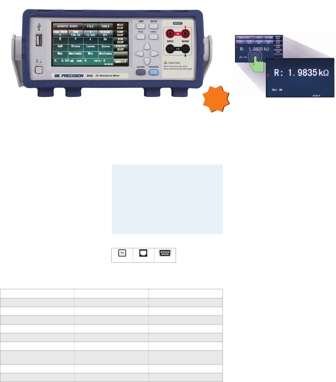
Component Testers
DC Resistance
Features
4.3-inch color touch screen
One touch full screen measurement view
Simultaneous display of two dierent
measurements (2841 only)
Four-terminal Kelvin type test
leads included
Temperature measurement with
correction (2841 only)
Low power test mode to protect DUT
Manual or Auto ranging
User selectable speed options
Maximum sample rate: 50 samples
per second
Oset voltage compensation (OVC)
Zero correction (0 ADJ)
Δ% mode for quickly determining the
percent dierence between components
Bin-sorting with Statistical functions
Comparator and pass/fail alarming
beeper function
Memory for 30 groups of parameters
Screen capture to USB drive
Automatically update operation soware
through USB
Power line filtering to eliminate the
influence of the power noise on
the instrument
Trigger delay
Handler interface
Standard RS232 and USBTMC interface
LAN interface (2841 only)
2840 Series DC Resistance Meters
The 2840 Series DC resistance meters feature
high accuracy and resolution. Both meters
are ideally suited for measuring contact
resistance of relays, switches, interconnects,
PCB traces, bonds, and cables. The 2841 adds
extended range, accuracy and temperature
measurement for evaluating coils, motor
windings, transformers, actuators and
conductive materials. The 2840 is
economically priced to meet the need of
applications where extended range and
temperature correction are not required.
Large color touch screen with user-friendly
interface provides intuitive operation. Using
the soware keypad of the touch screen,
users can easily set various functions
and values.
Handler interface with high-speed
measurement capabilities enable the 2840
Series to be used for evaluating and bin
sorting of large component quantities.
NEW
Model 2840 2841
Measurement range 1 µΩ - 20 kΩ 0.1 µΩ - 110 MΩ
Basic accuracy 0.05% 0.01%
Measurement resolution 1 µΩ 0.1 µΩ
Displayed measurements 11 or 2
Measurement functions* R and LPR R, R-T, T, LPR, LPR-T
Ranges 4 + Auto 11 + Auto
Temperature measurements
(TC and △t) -- √
Bins 310
Remote interface RS232, USB (USBTMC) LAN, RS232, USB (USBTMC)
*R – Resistance, LPR – Low Power Resistance, T - Temperature
Applications
Both meters are ideally suited for measuring
contact resistance of relays, switches,
interconnects, PCB traces, bonds, and cables.
The 2841 adds extended range, accuracy and
temperature measurement for evaluating
coils, motor windings, transformers,
actuators and conductive materials.
Touch screen to zoom or enter values
USB LAN* RS232
*2841 only
44
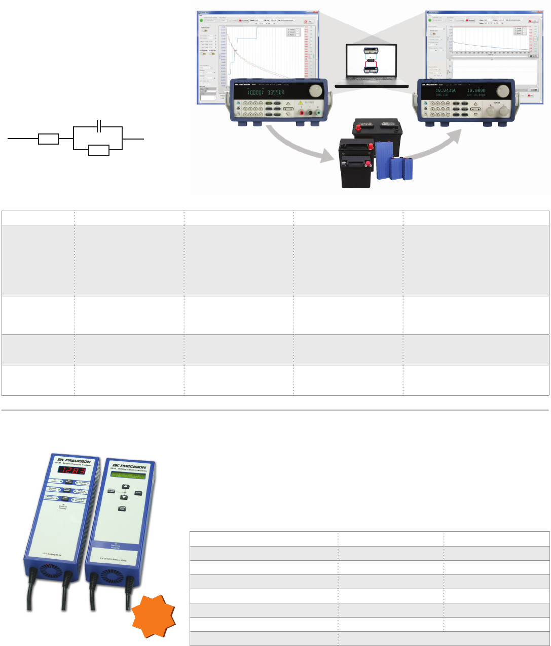
Battery Test
Overview, Handheld Battery Analyzers
600B & 601B Handheld Battery Capacity Analyzers
The 600B and 601B Handheld Battery Capacity Analyzers address the need to test and maintain
sealed lead acid (SLA) batteries used in backup power UPS, emergency lighting, fire alarms,
security systems, and many other electrical systems. By quickly characterizing a battery’s
response to a load resistance, these meters display the remaining battery capacity as an
indicator of the battery’s health.
Model 600B 601B
Supported SLA battery voltages 12 V 6 V & 12 V
Ah range 7, 12, 24, 42, 65, & 100 5 - 100 in 1 Ah steps
No load (open circuit) voltage accuracy ±2 counts ±(0.2% + 1 count)
Internal resistance -- ✓
Load voltage -- ✓
Dimensions (W x H x D) 74 x 265.1 x 54 mm 74 x 265.1 x 58 mm
Weight 1.2 kg
Battery Test Solutions
B&K Precision oers a wide array of internal
resistance/impedance based battery test
solutions including handheld and benchtop
units for field environments, labs, quality
control, and production use, as well as
frequency response analyzers for complex
AC impedance data analysis and charge/
discharge systems.
Battery charge/discharge solution with sequencing and data logging
Charge Discharge
Power Supply DC Electronic
Load
Model 9200/9115 & 8600/SDL Series 600B & 601B BA6010 & BA6011 FRA8000
Test method Charge / Discharge
Charge and discharge
battery while logging results
DC Resistance
Measure open and loaded
battery voltage
AC Impedance
Uses a 1 kHz fixed frequency
AC signal to calculate battery
impedance
EIS (electrochemical impedance
spectroscopy)
Stimulate the battery with a low-level
sinusoidal AC current at a particular
frequency and then measure both
the stimulating AC current and the
resultant AC voltage. Repeat for various
frequencies.
Result V/I plots with calculated
amp-hours (Ah) or C-rate
Calculates internal
resistance and displays
remaining capacity of
lead-acid battery in %
Real-time display of voltage,
impedance, phase angle and
capacitance
Real-time display of voltage, current
and impedance. Generates Nyquist and
Bode plots to identify specific battery
model elements.
Advantages Measures actual capacity of
a battery directly Quick, easy and repeatable
measurement
Fast measurement speed.
Ability to measure battery
capacitance.
Provides large amount of data and
detailed information about individual
battery model elements
Disadvantages Time consuming Ignores battery capacitance,
resistive battery model
elements lumped together
Individual battery model
elements seen as one
impedance value Requires complex data analysis
Model of simplied Randles cell
RS
Cdl
Rct
NEW
45
www.bkprecision.com
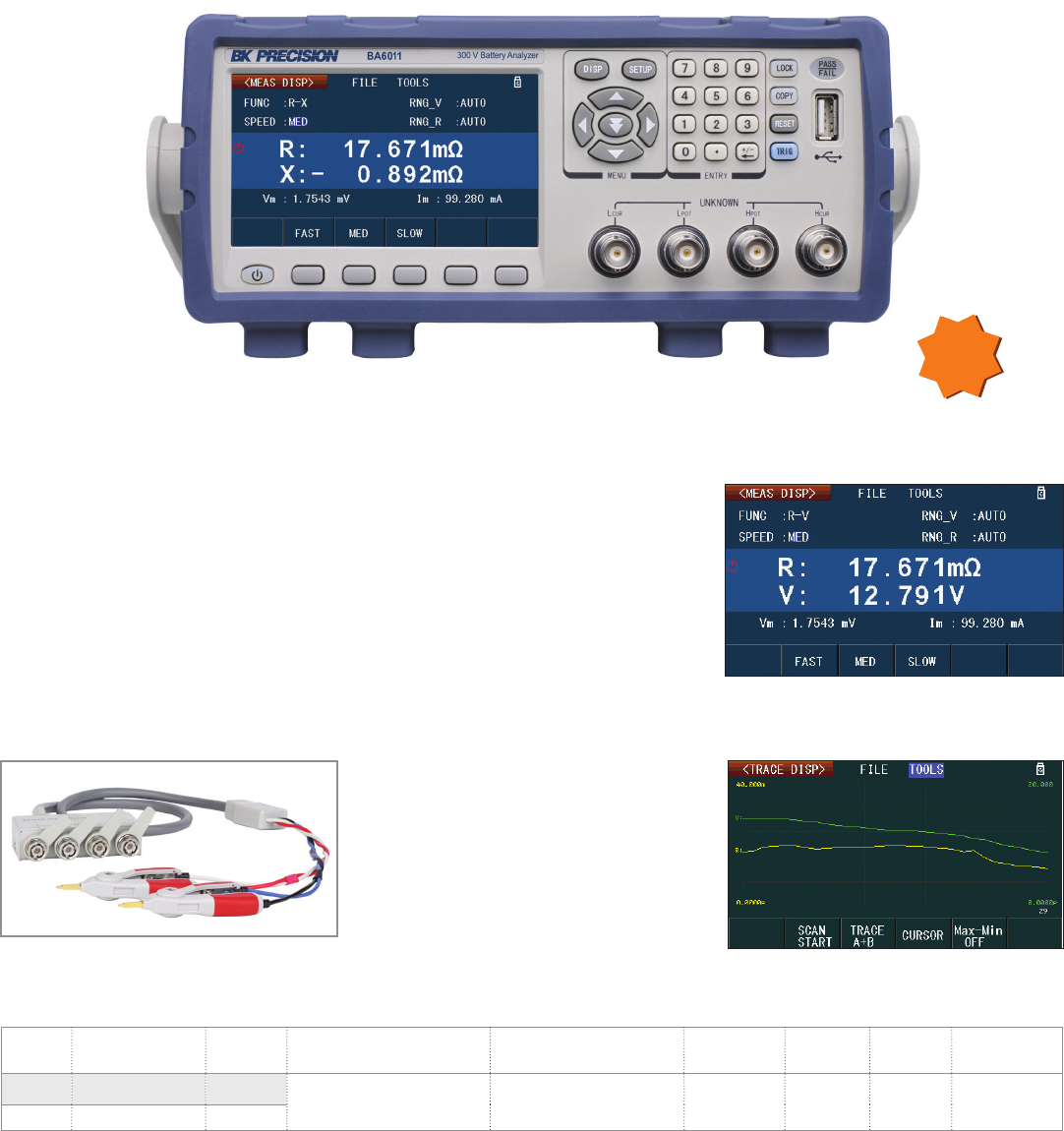
Battery Test
Battery Analyzers
BA6010 Series Battery Analyzers
The BA6010 Series Battery Analyzers use a
1 kHz AC constant current source to measure
the battery’s impedance expressed by
11 dierent measurement functions. With
a basic voltage and impedance accuracy
of 0.1% and micro-ohm resolution, these
instruments are well-suited for analyzing
a wide range of battery types and
configurations in the lab, quality control and
manufacturing environments.
Features & Benefits
4.3 inch color LCD display
Graphing display of voltage and resistance
with on-screen measurement tools
4-wire test fixture with monitoring for Hi
drive open, Low drive open, and
both open
Compare and sort using 10 bins with
statistical evaluations
Δ% mode for quickly determining the
percent dierence between batteries
Pass/Fail indicator with audible tone
Fast test speed up to 50 measurements
per second
Handler interface
Internal and external file storage
Model Input voltage Input
range
Measurement functions
(displayed) Test signal Basic accuracy
impedance
Impedance
resolution
Voltage
resolution Remote interface
BA6010 100 uV to 60 V 6 V / 60 V R, R-V, V, R-Q, L-Q, L-R, R-X, C-D,
Z-Q, Z-R and R-C Sine wave (1 kHz ±0.2 Hz) 0.1% 1 µΩ 100 µV RS232, USB
BA6011 100 uV to 300 V 30 V / 300 V
Dual Display
Data logging
NEW
TLKB1 - Kelvin test lead
46
Battery Test
Frequency Response Analyzer
FRA8000 Frequency Response Analyzer
In combination with a DC electronic load, the FRA8000
can be used to perform electrochemical impedance
spectroscopy (EIS) measurements for analysis of:
Primary and secondary batteries
Super capacitors and fuel cells
Corrosion and surface treatments
Features & Benefits
Compatible with any DC load that has a
programmable analog input to measure
high-voltage or high-power battery packs
High selectivity two stage receiver
architecture for high noise immunity
Simultaneous V/I measurement to ensure
exact impedance and phase information
Auto gain control and flexible ranges
for measuring small signals in noisy
environments with micro-ohm sensitivity
Adjustable sampling interval
USB, GPIB, and LAN connectivity
DDS sinewave generation yielding
frequency errors less than 0.02 Hz
Signal overload protection
Analysis Software Features
Nyquist, Bode, and V/I graphs
Real-time display of impedance
measurements and operating conditions
Frequency sweeps with adjustable
amplitude in log/linear form
Automatic or manual scaling and shiing
of screen plots for optimum viewing
Advanced marker functions
User-friendly control panel with auto-gain,
auto-sample, and logging capabilities
Nyquist diagram
AC source
Programmable frequency range 0.1 Hz - 20 kHz
Frequency resolution 0.01 Hz
Amplitude Up to 20% of DC bias setting or 1 Vrms
Amplitude resolution 5 mVpp
Distortion < 0.2%
DC bias
source
Range 10 mV – 10 V
Resolution 10 mV
Accuracy 0.1% ± 50 mV
Output impedance 50 Ω
Analyzer/
measurement unit
Range Auto
Sensitivity 1 µV
Dynamic range 120 dB
Sample Interval: 10 ms - 10 s
Phase accuracy 1°
Basic amplitude accuracy +/-2% 0.1 Hz – 9.99 Hz,
+/- 0.5% 10 Hz – 9999 Hz,
+/-1% 10 kHz – 20 kHz
NEW
The FRA stimulates the battery via the DC load’s analog programming input with a small sinewave signal at a
specic frequency, measures the battery's voltage and current response and calculates the complex impedance.
The FRA measurement unit is capable of extracting very small signals from noisy waveforms and compare their
gain and phase. The stimulus signal is swept from frequencies as low as 0.1 Hz to the desired
maximum frequency.
EIS diagram
V/I plot
Ext. analog prog
Current sense Voltage sense
Hall eect
USB/LAN
Log/Analyze
Input
DC Electronic Load
Frequency Response Analyzer
47
www.bkprecision.com
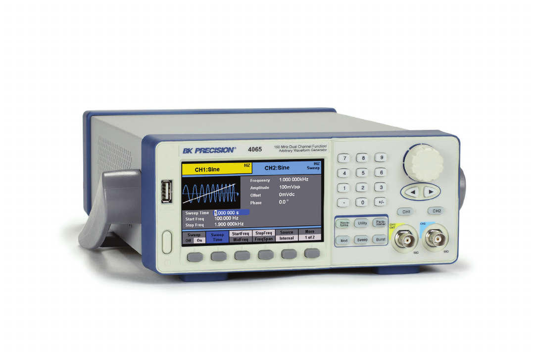
SIGNAL GENERATORS
Stimulus signals for design and test
48

Signal Generators
Selection Guide
Type Frequency
range
Number
of
channels
Arbitrary Modulation Output
range
(into 50 Ω)
Interface Special
features Model Page
Waveform
length
Sample
rate
Vertical
resolution AM / FM Other
Performance
Arbitrary &
Function
Generator*
1 uHz-30 MHz 11 Mpts 200 MSa/s 14 bit int/ext FSK 10 mV-10 Vpp USB marker 4075B 51
1 uHz-30 MHz 21 Mpts 200 MSa/s 14 bit int/ext FSK 10 mV-10 Vpp USB marker 4078B 51
1 uHz-50 MHz 14 Mpts 200 MSa/s 14 bit int/ext FSK 10 mV-10 Vpp USB, GPIB
marker,
summing input
4076B 51
1 uHz-50 MHz 24 Mpts 200 MSa/s 14 bit int/ext FSK 10 mV-10 Vpp USB, GPIB 4079B 51
1 uHz-80 MHz 116 Mpts 200 MSa/s 14 bit int/ext FSK 10 mV-10 Vpp USB, GPIB 4077B 51
1 uHz-80 MHz 216 Mpts 200 MSa/s 14 bit int/ext FSK 10 mV-10 Vpp USB, GPIB 4080B 51
Basic
Arbitrary &
Function
Generator**
1 uHz-10 MHz 216 kpts 150 MSa/s 14 bit int/ext ASK, FSK, PM, PSK,
DSB-AM, PWM 2 mVpp-10 Vpp USB, LAN,
GPIB option
counter, color
display 4053B 53
0.01 Hz-20 MHz 11 kpts 50 MSa/s 12 bit int/ext -10 mV-10 Vpp USB counter 4045B 53
0.01 Hz-25 MHz 216 kpts 125 MSa/s 14 bit int/ext FSK, PM, PWM 10 mV-10 Vpp USB counter 4047B 53
1 uHz-30 MHz 216 kpts 150 MSa/s 14 bit int/ext
ASK, FSK, PM, PSK,
DSB-AM, PWM 2 mVpp-10 Vpp
USB, GPIB
option
counter, color
display
4054B 53
1 uHz-60 MHz 216 kpts 150 MSa/s 14 bit int/ext 4055B 53
1 uHz-80 MHz 216 kpts 500 MSa/s 14 bit int/ext
USB, GPIB
option
counter,
color display
4063 52
1 uHz-120 MHz 216 kpts 500 MSa/s 14 bit int/ext 4064 52
1 uHz-160 MHz 216 kpts 500 MSa/s 14 bit int/ext 4065 52
Note: All generators produce basic function generator waveforms sine, square, triangle, TTL/CMOS and ramp/pulse and complex waveforms including noise, sin(x)/x, exponential and Gaussian
* = True AWG capable of generating almost any waveform combined with full function generator functionality (two in one)
** = Primarily DDS function generators with basic Arb. capability in terms of memory space, vertical resolution, and maximum output frequency
Arbitrary/Function Generators
Type Frequency
range
Waveforms Modulation Sweep Burst Output range
(into 50 Ω) Interface Special
features Model Page
Basic *) Other AM/FM Other lin/log
Digital (DDS)
1 Hz-5 MHz √ - - - - - 10 mV-10 Vpp - - 4005DDS 54
0.1 Hz-7 MHz √ - - - √ - 10 mV-10 Vpp - - 4007B 54
0.1 Hz-12 MHz √ - - - √ - 10 mV-10 Vpp - - 4013B 54
0.01 Hz-12 MHz √ - int/ext - √ - 10 mV-10 Vpp USB counter 4014B 54
0.01 Hz-20 MHz √ - int/ext - √ √ 10 mV-10 Vpp USB counter 4040B 54
Analog
0.2 Hz-2 MHz √ - - - - - 100 mV-10 Vpp - - 4010A 56
0.5 Hz-4 MHz √ - - - √ - 100 mV-10 Vpp - - 4001A 56
0.5 Hz-4 MHz √ - - - √ - 100 mV-10 Vpp -counter 4003A 56
0.5 Hz-5 MHz √ - - - - 100 mV-10 Vpp - - 4011A 56
0.5 Hz-5 MHz √ - - - √ - 100 mV-10 Vpp - - 4012A 56
0.1 Hz-10 MHz √ - - - √ - 100 mV-10 Vpp - - 4017A 56
0.2 Hz-20 MHz √ - int/ext - √ √ 100 mV-10 Vpp -counter 4040A 56
Function Generators
Note: *) basic waveforms include sine, square, triangle, TTL/CMOS and ramp/pulse
Type Frequency range Transition time Width Delay Number of outputs Model Page
Analog 0.1 Hz-10 MHz 12 ns 50 ns - 50 ms 0 - 2 µs 14030 56
Digital 0.1 Hz-50 MHz 6 ns - 100 ms 10 ns - 10 s 0 - 10 s 14033 55
0.1 Hz-50 MHz 6 ns - 100 ms 10 ns - 10 s 0 - 10 s 24034 55
Type Frequency range Waveforms Modulation Output range Model Page
Sine Square AM
Audio 20 Hz-150 kHz √ √ - 0-1.2 Vpp 3001 56
Signal 0.1 Hz-10 MHz √ √ - 0-4.5 Vpp (no load)(sine), 5 Vpp (no load)(square) 3003 56
100 kHz-150 MHz √ - int/ext 100 mVrms max. 2005B 56
Pulse Generators
Other Signal Sources
49
www.bkprecision.com
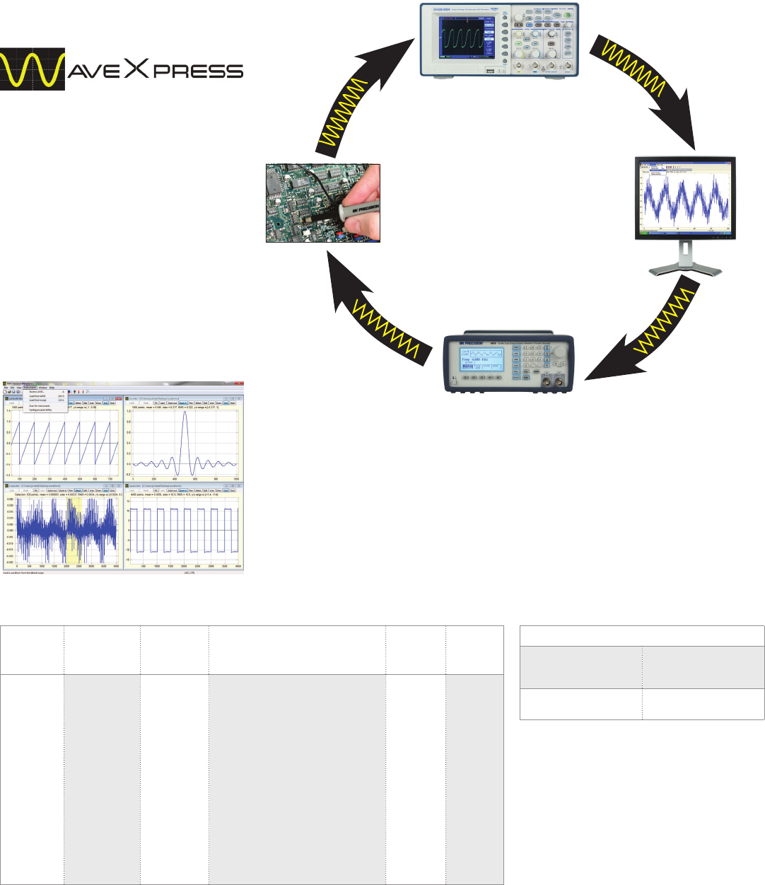
Signal Generators
WaveXpress Soware
Signal Generators
WaveXpress Soware
WaveXpress is a comprehensive stand-alone
application with several transformation
options, allowing users to easily create
complex waveforms. Modify a waveform
downloaded from a scope or construct a new
waveform using powerful and intuitive
editing tools. Quickly download them to
your AWG and begin testing your circuits
and systems moments later. The WaveXpress
program can also be used for general-purpose
waveform editing without requiring any
instruments to be connected to the computer.
Features & Benefits
Import waveforms from B&K scopes, AWGs, or load them from CSV or text files
Autoscan function automatically detects instruments connected via RS232, USB, or GPIB
Generate waveforms from scratch with drawing and editing tools.
Insert commonly used waveforms and dierent types of noise
Numerous transformations for changing a waveform. User-defined transformations can be
added in the python programming language
Multi-language support: additional languages can be added by the user
Fast zooming and panning with mouse
Dialog settings are remembered for faster repetitive work
Undo/redo functions allow quick experimentation
Waveforms Filters Noise Transformations
Supported
file
formats
Supported
interfaces
Sine
Square
Triangle
Sawtooth
Pulse
Sinc
Noise
Exponential
Rise/Decay
Savitzky-Golay
smoothing
Low-pass
Band-pass
High-pass
Notch
Beta
Chi Square
Exponential
F
Gamma
Laplace
Lognormal
Logistic
Normal
Rayleigh
Uniform
Weibull
Linear (ax + b)
Gaussian noise
Clip
Resample
Convert to DC (max, min, average, or RMS)
Signum
Absolute value
Sort ordinates
Reverse ordinates (mirror about vertical axis)
Dierentiate
Integrate
Make positive
Normalize amplitude to unity
Zero amplitude
Negate (mirror about horizontal axis) CSV,
ASCII,
proprietary BKW file
CSV, ASCII,
proprietary
BKW file
RS232/USB/
GPIB
Download Information:
www.bkprecision.com/WaveXpress
System requirements:
Windows XP or later
NI-VISA Run-Time Engine*
*Download from the NI website link below:
http://joule.ni.com/nidu/cds/view/p/id/1606/lang/en
Supported Instruments
Oscilloscopes 2540C (-MSO) Series,
2550 Series, 2560
Series
AWGs 4045B, 4047B,
4075B - 4080B Series
GENERATE
Waveform creation capabilities
VALIDATE
CAPTURE
EDIT
50
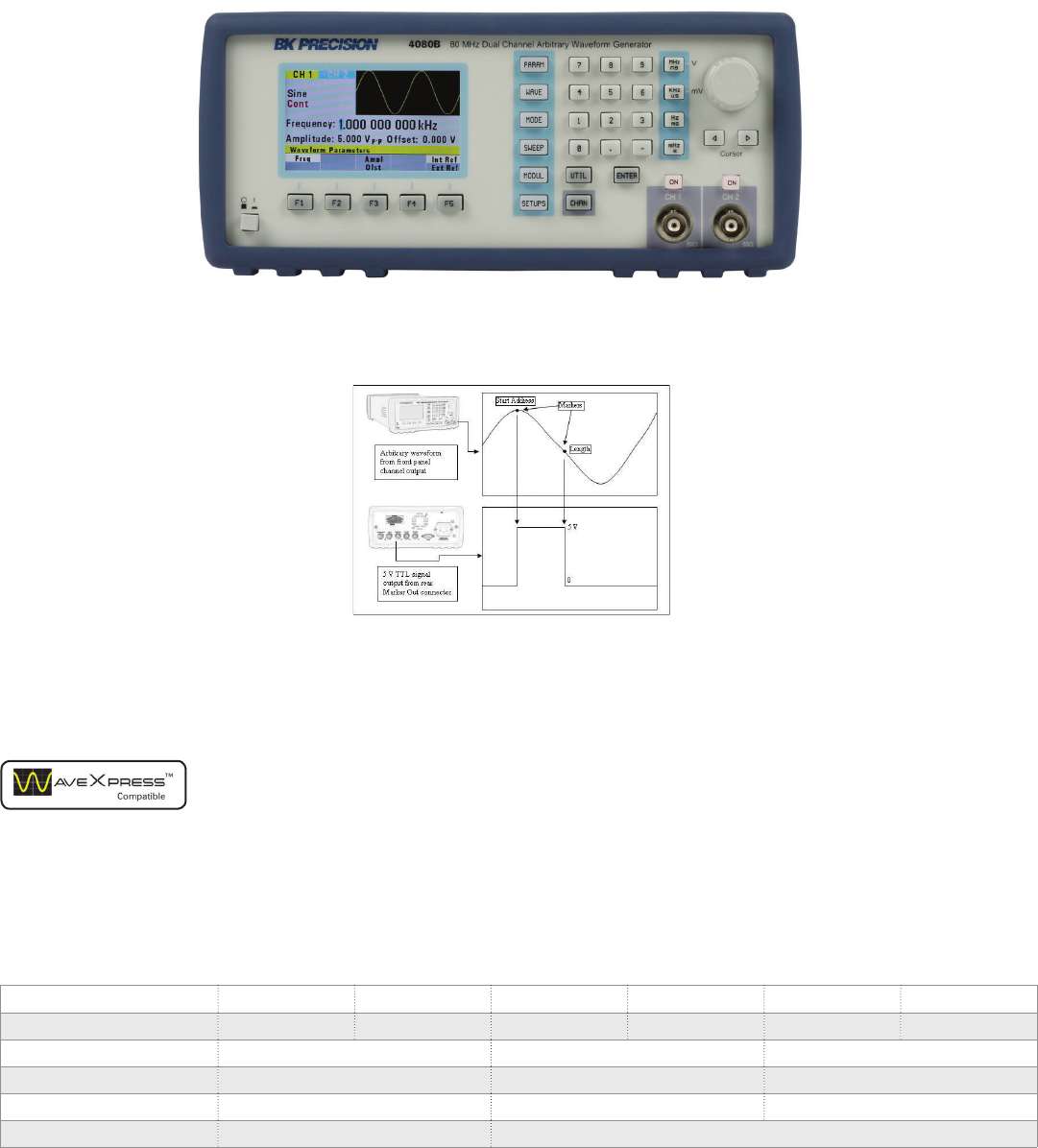
Signal Generators
True AWG
Dual architecture design
These generators combine the benefits of
DDS (direct digital synthesis) and true AWG
(arbitrary waveform generator) architectures
without the limitations of either. Standard
waveforms such as sine, square, and triangle
are generated with a DDS chip, delivering
great frequency resolution at a low cost.
Custom arbitrary waveform generation is
implemented with a true point-by-point
design, oering improved signal integrity
by producing significantly less jitter and
distortion compared to a DDS-only
architecture.
4075B Series Arbitrary/Function Waveform Generators
Model 4075B 4078B 4076B 4079B 4077B 4080B
Channels 121212
Sine frequency range 1 µHz – 30 MHz 1 µHz – 50 MHz 1 µHz – 80 MHz
Square frequency range 1 µHz – 30 MHz 1 µHz – 50 MHz 1 µHz – 60 MHz
Arbitrary waveform length 1 Mpts 4 Mpts 16 Mpts
Remote interface USBTMC USBTMC and GPIB
Programmable markers
The 4075B Series provides fully
programmable markers that allow you to
generate a positive TTL level output signal at
the points specified by address in memory
and length up to 4000 points.
Features & Benefits
14-bit, 200 MSa/s, 16 Mpts arbitrary
waveform generator
Linear and logarithmic sweep
AM/FM/FSK modulation
Output ON/OFF button
Gate and burst mode
Fully programmable markers
Store/recall up to 50 instrument settings
SCPI-compliant command set
Short circuit protection on output
Flexible memory management
The 4075B Series gives users more freedom
by allowing the flash memory to be allocated
via start address and length parameter set-
ups. For instance, a model 4080B user could
generate one large 16M-point waveform or
up to 49 dierent waveform setups totaling
16 Mpts in one memory bank. Up to eight
non-volatile memory banks are available to
store arbitrary waveforms with 14-bit vertical
resolution.
51
www.bkprecision.com
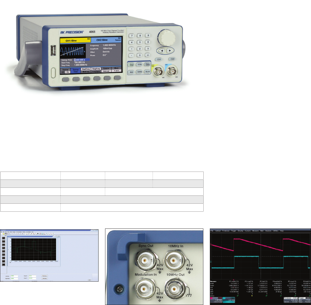
Signal Generators
Function Generators/AWG
Generate waveforms with ease
The provided waveform editing soware can
be used to create point-by-point arbitrary
waveforms via freehand or waveform
math functions.
Advanced pulse generator
The 4060 Series can generate pulses with
minimum rise/fall times of 6 ns and maximum
rise/fall times of 6 seconds.
4060 Series Dual Channel Function/Arbitrary Waveform Generators
The 4060 Series Dual Channel Function/Arbitrary Waveform Generators are capable of
generating stable and precise sine, square, triangle, pulse, and arbitrary waveforms. With an
easy-to-read color display and intuitive user interface with numeric keypad, these instruments
oer plenty of features including linear/logarithmic sweep, built-in counter, extensive
modulation and triggering capabilities, a continuously variable DC oset, and a high
performance 14-bit, 500 MSa/s arbitrary waveform generator.
Model 4063 4064 4065
Sine frequency range 1 µHz – 80 MHz 1 µHz – 120 MHz 1 µHz – 160 MHz
Square frequency range 1 µHz – 40 MHz 1 µHz – 50 MHz
Weight 2.8 kg
Dimensions (W x H x D) 261 x 105 x 344 mm
Synchronization and external triggering
Use the external 10 MHz clock input and
output to synchronize your signals to a
master time base.
Features & Benefits
14-bit, 500 MSa/s, 512k point arbitrary
waveform generator
Two independent channels with one
button synchronization
Large 4.3-inch LCD color display
Linear and logarithmic sweep
AM/DSB-AM/ASK/FM/FSK/PM/PWM
modulation functions
Variable DC oset
Highly adjustable pulse duty cycle from
0.0001% to 99.9999%
Internal/external triggering
Gate and burst mode
36 built-in predefined arbitrary waveforms
Store/recall up to 10 instrument settings
and 32 user-defined arbitrary waveforms
Built-in counter
USB device port (USBTMC-compliant) with
front panel USB host port
GPIB connectivity with optional
USB-to-GPIB adapter (model AK40G)
Short circuit output protection
LabVIEW drivers available
52
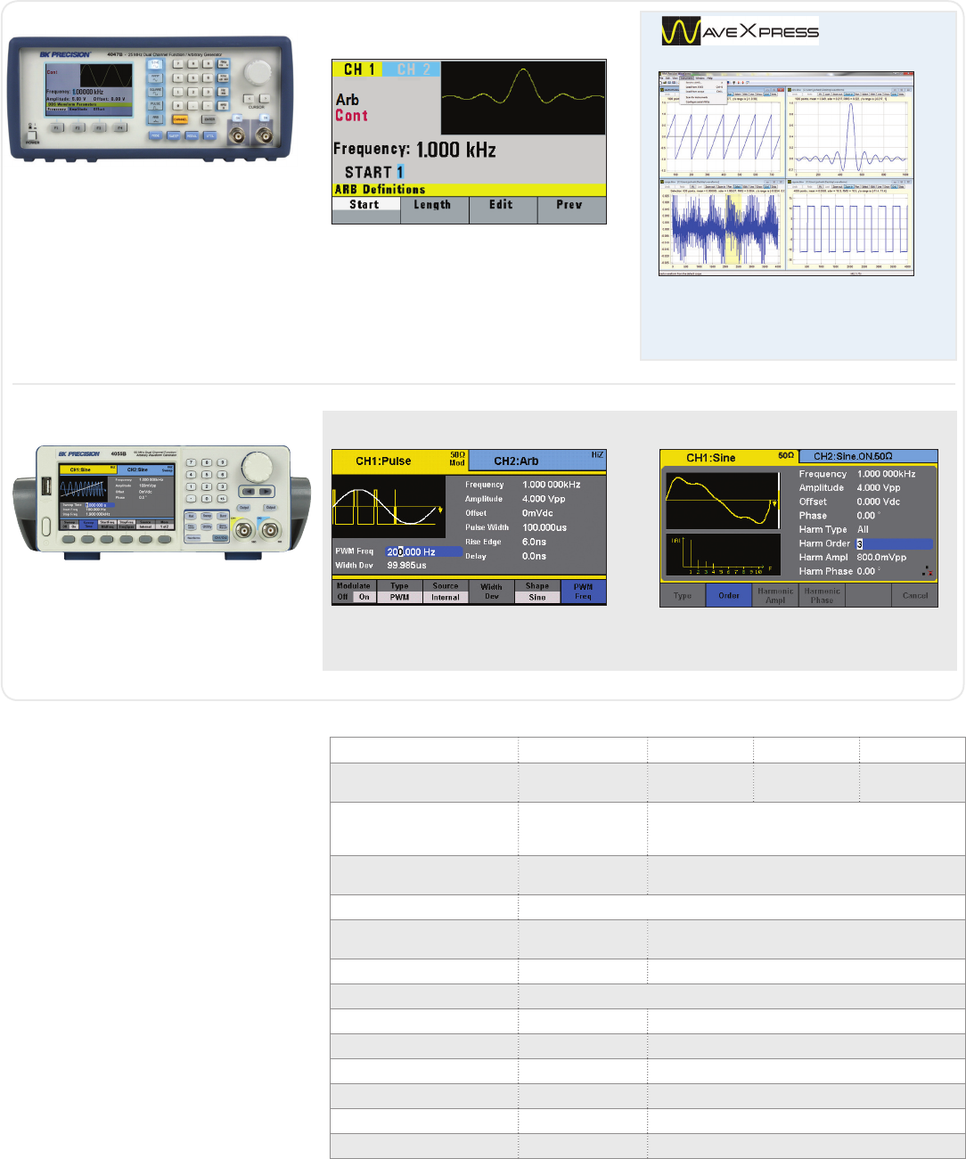
Signal Generators
Function Generators/AWG
Dual-Channel Function/Arbitrary Waveform Generators
The 4047B is a versatile dual-channel
25 MHz function generator with arbitrary
waveform capability. It features a true
point-by-point AWG (arbitrary waveform
generator) architecture to produce accurate
and precise arbitrary waveforms combined
with a DDS architecture oering easy-to-use
conventional function generator capabilities.
Model 4047B 4053B 4054B 4055B
Sine & Square
frequency range 0.01 Hz - 25 MHz 1 µHz - 10 MHz 1 µHz - 30 MHz 1 µHz - 60 MHz
Amplitude 0 - 10 Vpp into 50
ohms for entire
frequency range
0 - 10 Vpp into 50 ohms, ≤ 10 MHz
0 - 5 Vpp into 50 ohms, >10 MHz
Modulation AM, FM, FSK, PM,
PWM AM, DSB-AM, FM, PM, ASK, FSK, PSK, PWM
Vertical resolution 14 bit
AWG architecture True point-by-
point AWG DDS-based AWG
Sample rate 125 MSa/s 150 MSa/s
Arbitrary waveform length 16 kpts
Built-in arbitrary waveforms 9196
Dedicated waveform keys √ -
Channel tracking - √
Harmonics generator - √
Ext 10 MHz reference I/O - √
Remote interface USB (Virtual COM) LAN, USB device (USBTMC), USB host interface
Front panel arbitrary waveform generation
From the front panel, waveforms can be
dened from scratch by entering data
point-by-point or by loading and modifying
predened waveforms.
Waveform editing software
Use WaveXpress to easily generate, edit, and upload
custom arbitrary waveforms to the generator via the
remote interface. Generate waveforms in the software
by importing a text le or dene via freehand, point
draw, and waveform math functions.
Common Features
4.3” color LCD display
Two fully independent channels with
individual output On/O buttons
Synchronize the phase of both channels
with the push of a button
Low-jitter square wave generation for
simulating reliable clock signals,
generating triggers, or validating serial
data buses
Linear and logarithmic sweep
Variable DC oset
Adjustable duty cycle
Internal/external triggering
Gate and burst mode
Built-in frequency counter
The 4050B Series dual-channel function/
arbitrary waveform generators are capable
of providing stable and precise sine, square,
triangle, pulse, and arbitrary waveforms up
to 60 MHz, using a DDS-based architecture.
Wide variety of modulation schemes
These instruments are capable of many dierent
types of modulation for various applications.
Harmonics generator function
Generate up to 10 harmonics with independent
amplitude and phase settings.
4047B
4050B Series
53
www.bkprecision.com
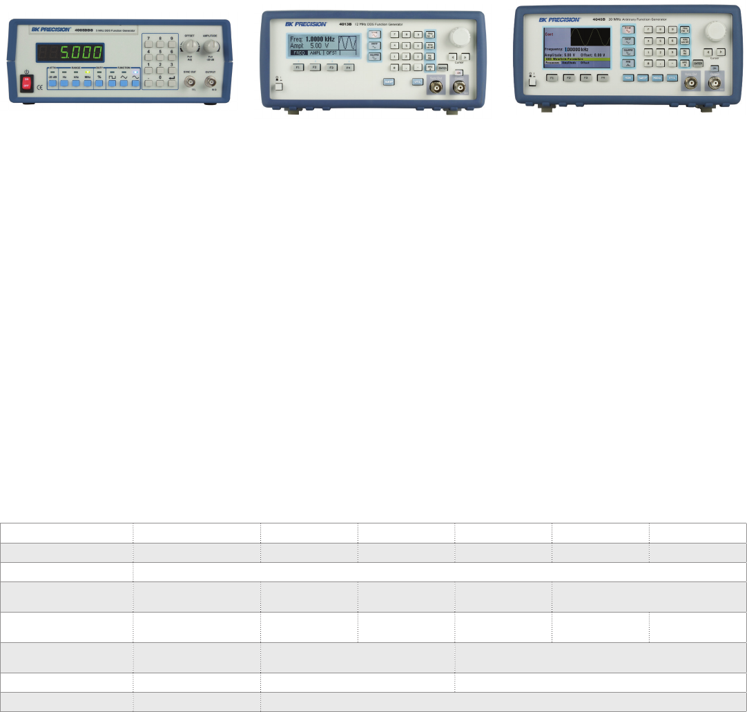
Signal Generators
Digital (DDS) Function Generators
The 4005DDS is a versatile 5 MHz function
generator using a DDS (direct digital
synthesis) design. This model is great for
education and other applications that need
basic waveform generation.
Specifications 4005DDS 4007B 4013B 4014B 4040B 4045B
Frequency (sine & square) 1 Hz - 5 MHz 0.1 Hz - 7 MHz 0.1 Hz - 12 MHz 0.01 Hz - 12 MHz 0.01 Hz - 20 MHz 0.01 Hz – 20 MHz
Output range (into 50 Ω) 10 mV - 10 Vpp
Flatness ±0.3 dB to 1 MHz,
±1 dB to 5 MHz ±1 dB to 7 MHz ±1 dB to 12 MHz ±0.5 dB to 1 MHz,
±1 dB to 12 MHz ±0.5 dB to 1 MHz,
±1 dB to 20 MHz
Arbitrary waveform
generator -- -- -- -- -- 0.01 Hz – 20 MHz
Variable duty cycle 20% - 80% to 3 MHz
for square 20% - 80% to 1 MHz
for square 20% - 80% to 2 MHz for square,
1% - 99% in 1% steps for triangle
Weight 2.3 kg 2 kg 2.5 kg
Dimensions (W x H x D) 279.4 x 101.6 x 297.2 mm 213 x 88 x 210 mm
Features & Benefits
Sine, square, and triangle waveforms up
to 5 MHz
Numeric keypad for quick input
of frequency
Adjustable DC oset
Adjustable duty cycle
Front panel push button and pull knob
can attenuate output by up to 40 dB
Model 4005DDS
The 4007B, 4013B, 4014B, 4040B, and 4045B
DDS function generators are capable of
generating stable and precise waveforms. All
models provide variable output amplitudes
from 0 to 10 Vpp into 50 Ω and a continuously
variable DC oset to inject signals into circuits
at the correct bias level. Standard features
include an intuitive menu-driven front panel
keypad, rotary control knob, adjustable duty
cycle, and comprehensive short circuit and
overvoltage output protection.
Common Features
Sine, square, and triangle waveforms
Bright LCD display with waveform preview
Linear and logarithmic sweep
Store and recall instrument settings
Output On/O button
Additional Features (4014B/4040B/4045B)
AM/FM modulation
Low-jitter square wave generation for
simulating reliable clock signals,
generating triggers, or validating serial
data buses
Internal/external triggering
Gate and burst mode (4040B)
Built-in counter
USB interface and SCPI-compliant
command set
Remote control application
soware provided
Arbitrary waveform generation (4045B)
Model 4013B Model 4045B
54
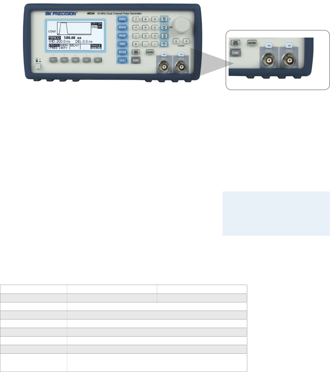
Signal Generators
Performance Pulse
Dual-Channel Model 4034
Users can save cost and bench space with two
independent channel outputs. Both channels
oer full functionality and all parameters
such as pulse width and transition time can
be set individually. The channels can also be
synchronized with the push of a button.
Applications
• Automatic Test Equipment (ATE)
• Avionics and radar testing
• Switching power supply testing
• Characterization of active components
4033 & 4034 50 MHz Programmable Pulse Generators
The 4033 and 4034 are high performance
programmable pulse generators ideal for
testing digital systems and circuits based on
TTL, CMOS, or ECL technologies. Both
instruments generate clean and accurate
pulses at up to 6 digits resolution with a
repetition rate up to 50 MHz, variable pulse
widths from 10 ns to 10 s, and pulse delays
from 0 ns to 10 s. Output levels are
adjustable from -10 V to +10 V, with pulse
amplitudes settable from 0.1 Vpp to 10 Vpp
into a 50 Ω load.
All parameters, modes, and functions are
programmable via the front panel or remote
control commands. Additionally, the pulse
generators provide selectable
complementary pulse and double pulse
generation in continuous, triggered, gated,
and counted burst modes.
Features & Benefits
Repetition rate of 0.1 Hz to 50 MHz
Flexible trigger modes: Continuous,
Triggered (internal, external, manual),
Gated Burst and External Width
Pulse width programmable from 10 ns
to 10 s
Transition times (rise and fall times)
variable from 6 ns to 100 ms
Programmable delay and double pulse
Predefined amplitude levels for ECL,
TTL, and CMOS signals
Store up to 99 dierent test setups with
auto retention of last power down setup
Pulse amplitudes up to 10 Vpp into
50 Ω output
Programmable via GPIB and RS232
SCPI compatible
Specifications 4033 4034
Channels 1 2
Frequency 0.1 Hz to 50 MHz
Period 40 ns to 10 s (25 MHz to 0.1 Hz repetition rate)
Width 10 ns to (Period – 10 ns)
Delay 0 ns to (Period – Width – 10 ns)
Duty Cycle 1% - 99%
Amplitude 0.1 V to 10 Vpp into 50 Ω load (20 Vpp max into open circuit)
Transition Times <6 ns to 100 ms variable. Leading and trailing edges settable separately and limited
to 20:1 ratio between settings into one of the following ranges: 5 ns-100 ns; 50 ns-1.0
us; 500 ns-10 us; 5.0 us-100 us; 50 us-1.0 ms; 500 us-10 ms, 5 ms – 100 ms
Æ
55
www.bkprecision.com
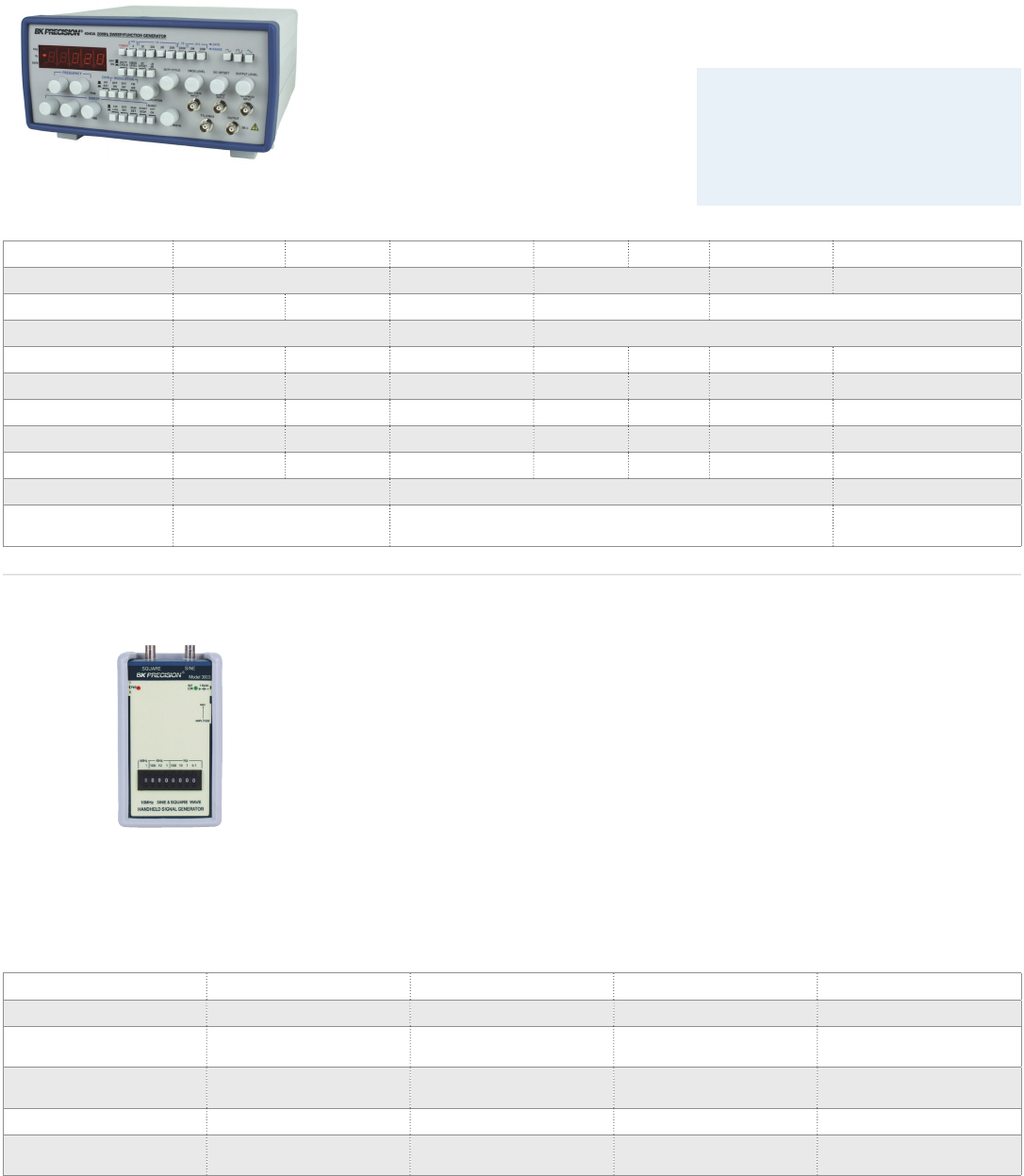
Signal Generators
Analog & Handheld
Common Features & Benefits
Variable output: 10 Vpp into 50 Ω
(includes a 20 dB attenuator)
TTL/CMOS output
Adjustable DC oset
Sine/square/triangle/ramp/pulse outputs
Specifications 4001A 4003A 4010A 4011A 4012A 4017A 4040A
Frequency range (sine) 0.5 Hz - 3 MHz 0.2 Hz - 2 MHz 0.5 Hz - 5 MHz 0.1 Hz - 10 MHz 0.2 Hz - 20 MHz
Frequency resolution -- 5 digits -- 4 digits 5 digits
Distortion <2%, 1 Hz - 100 kHz 4% typical at 1 kHz ≤3% typical at 1 kHz
VCG -- √ √ √ √ √ √
AM/FM modulation -- -- -- -- -- -- √
Linera/Log Sweep -- -- -- -- √-- √
Burst -- -- -- -- -- -- √
Counter -- up to 20 MHz -- -- -- -- up to 30 MHz
Weight 2.5 kg 1.8 kg 2 kg
Dimensions
(W x H x D) 275 x 90 x 300 mm 298 x 114 x 264 mm 298 x 140 x 264 mm
10 MHz Pulse Generator with 4-digit
LED Display
The 4030 pulse generator supplies positive
and negative 0.5-5 V pulses into 50 Ω at up
to 10 MHz pulse repetition frequency (pulse
periods from 100 ns to 100 ms). Pulse widths
are continuously variable between 50 ns and
50 ms and the pulses have rise and fall times
of 12 ns.
150 MHz RF Signal Generator
The 2005B supplies sine wave outputs from
100 kHz to 150 MHz (harmonics usable to
450 MHz) at up to 100 mV (RMS). An external
crystal can be plugged in for precise
frequency control. The output is provided via
a BNC female connector.
20 Hz-150 kHz Sine/Square Wave
Audio Generator
The 3001 generates low-distortion sine waves
at 46 discrete frequencies. Frequency
accuracy is 3% from 20 Hz to 100 kHz. The
unit is powered by a 9 V battery.
10 MHz Handheld Sine & Square Wave
Signal Generator
The 3003 generates up to 10 MHz sine
(adjustable amplitude from 0 to 4.5 Vpp,
no load) and TTL square waves using
DDS technology in steps of 0.1 Hz. Output
frequency accuracy is 0.02%. The sine and
square waves are available simultaneously
from separate BNC female connectors. A 9 V
battery supplies power or an external 6-9 VDC
adapter can be used.
Specifications 3001 3003 4030 2005B
Frequency Range 20 Hz - 150 kHz 0.1 Hz - 10 MHz 0.1 Hz - 10 MHz 100 kHz - 150 MHz
Output
Voltage > 1.2 V rms at max
setting(no load) 0 to 4.5 Vpp (no load) (sine)
5 Vpp (no load) (square) 1 - 10 V up to 100 mVrms
Output
Impedance 600 Ω 50 Ω 50 Ω 50 Ω - 200 Ω
Weight 200 g 0.9 kg 2.5 kg 2.5 kg
Dimensions
(W x H x D) 82 x 150 x 21 mm 97 x 145 x 38 mm 26.2 x 11.2 x 31.5 mm 250 x 150 x 130 mm
Model 4040A
Analog Function Generators
These analog function generators oer familiar controls, stable output, and reliable operation
at budget-saving price points. While DDS generators have eclipsed analog generators at the
high end, these analog generators are the workhorses of industry, education, and hobbyists.
Model 3003
Models 4011A and 4012A are popular 5 MHz
generators for general bench and lab use with
an ideal mixture of features at a compelling
price. The 4012A is identical to the 4011A, but
with a sweep function added.
56
SPECTRUM ANALYZERS
Essential tools for RF measurements
57
www.bkprecision.com
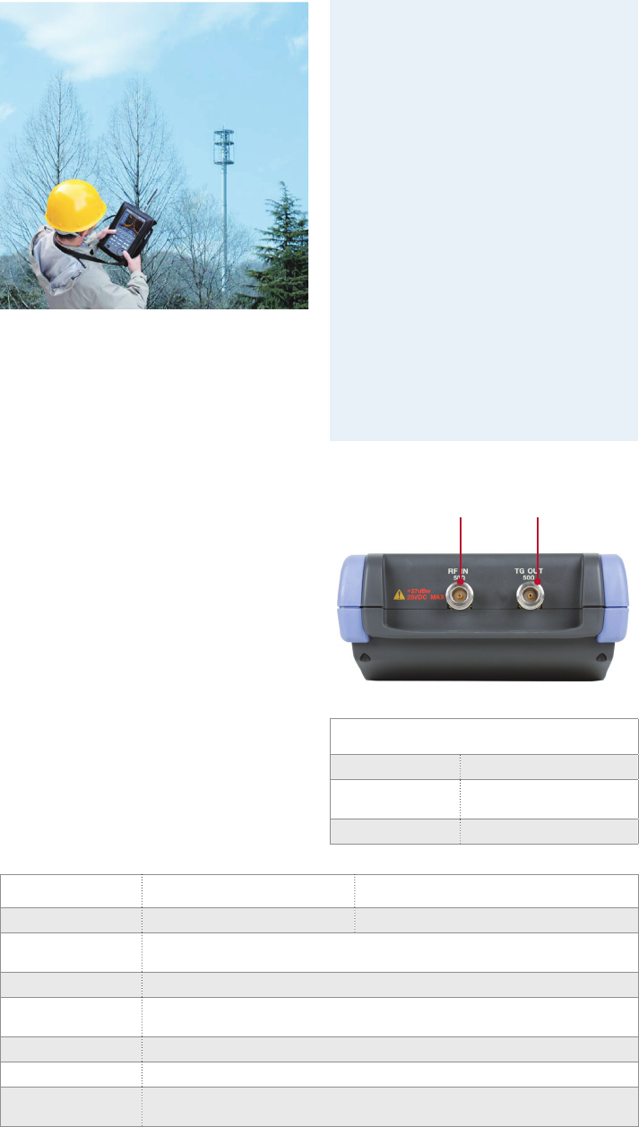
Spectrum Analyzers
Handheld Spectrum Analyzers
The 2650A series handheld spectrum
analyzers are compact, lightweight, and
cost-eective instruments for quick and
precise signal investigations. At a weight
of only 1.8 kg, the 2650A series are by far
the lightest full-featured spectrum analyzer
available, yet they deliver performance and
features comparable to full-size bench
spectrum analyzers and can operate up to
4 hours on a single battery.
With their ease of use, measurement
flexibility, and unmatched portability, the
2650A series analyzers are indispensable
tools for engineers and technicians who
conduct field measurements in the 50 kHz to
8.5 GHz range.
Applications
• Installation, maintenance, and
troubleshooting of wireless communication
systems such as W-CDMA/CDMA, GSM,
WLAN, WiMAX and Bluetooth
• Detection of signal interference and
undesired emissions
• TV and broadcasting
• Antenna alignment
• Electric field strength measurement with
dipole antennas optimized for typical
frequencies used in wireless systems
• Magnetic field strength measurement with
magnetic field probe (PR 26M)
• Frequency response measurements of
passive components such as RF cables,
filters, and attenuators using the built-in
tracking generator (2652A)
Features & Benefits
Frequency range from 50 kHz – 8.5 GHz
Truly portable spectrum analyzer
weighing only 1.8 kg including the battery
Impressive 4 hour battery life;
easy-to-replace rechargeable
Lithium-Ion battery
USB interface for PC connectivity
Intuitive PC soware for remote
control and documentation of
measurement results
Conveniently store measurement results
and screenshots in bitmap format to USB
flash drive (USB host interface)
Large easy-to-read color display
Measurement functions: channel /
adjacent channel power, occupied
bandwidth, electric and magnetic
field strength
Convenient Auto Tune function
automatically sets center frequency to the
maximum signal within full span and
optimum settings for RBW, VBW and
sweep time
External trigger for zero span
measurements
SCPI-like remote control commands
Superb performance improves
your productivity
Advanced synthesizer-based design
enables the 2650A series to provide you
with an accurate and detailed picture of
the spectrum you are investigating
Fast sweep speed (minimum 10 ms) to
help locate and identify elusive, transient
interference signals
DANL (displayed average noise level)
of -127 dBm
Single sideband phase noise – 90 dBc @
100 kHz oset
Tracking generator specifications (2652A)
Frequency range 5 MHz - 3.3 GHz
Output level -10 dBm ± 1 dB @ 1
GHz (output level is fixed)
Output flatness ±1.5 dB
Specifications 2650A/2652A 2658A
Frequency range 50 kHz - 3.3 GHz 50 kHz - 8.5 GHz
Resolution
bandwidth 3 kHz to 3 MHz (1-3 sequence) and AUTO
SSB phase noise -90 dBc/Hz (typical) @100 kHz oset
Average noise level -127 dBm (typical) @ CF : 1 GHz, RBW : 3 kHz, VBW : 100 Hz, Ref. level < - 40 dBm
(preamp automatically ON)
Input VSWR < 2.0
Weight approx. 1.8 kg (including battery)
Dimensions
(W x H x D) 162 x 71 x 265 mm
Input
(spectrum analyzer)
Output
(tracking generator)
58
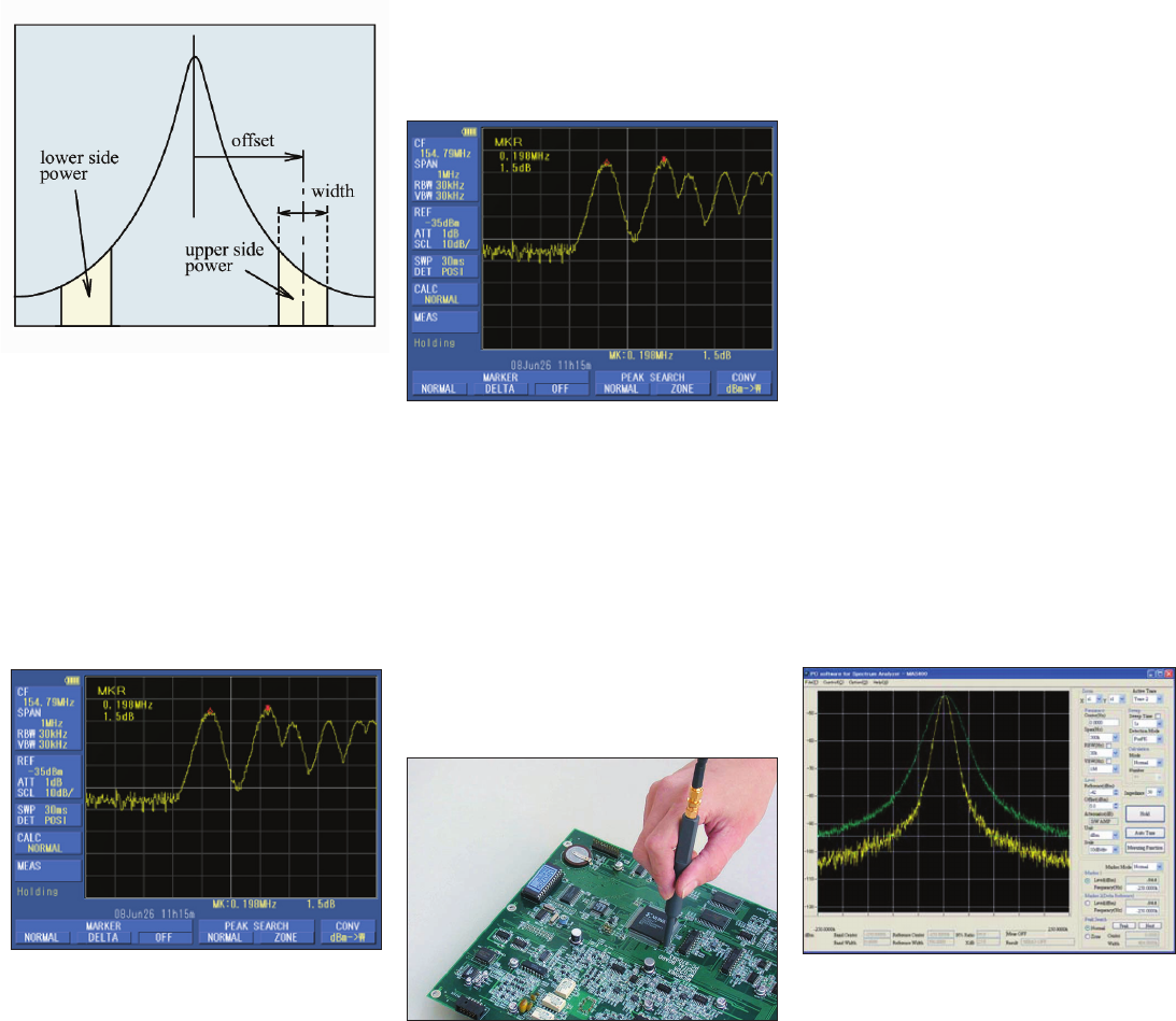
Spectrum Analyzers
Handheld Spectrum Analyzers
Channel Power Measurement
Allows you to measure the total power or
noise power in a user-specified bandwidth.
Adjacent Channel Power
Measures the ratio of power leakage (from the
wanted signal) into adjacent channels. Center
frequency, adjacent channel bandwidth, and
oset between main carrier and adjacent
channels can be set.
Electric Field Strength Measurement
An optional dipole antenna (models M401
thru M406) that connects to the RF input
enables the measurement of electric field
strength. Users can choose from 6 antennas
based on the frequency range
under investigation.
Combined with the MAX HOLD function and a
10 ms sweep time, the M404 dipole antenna
is capable of measuring the electric field
strength of Bluetooth systems and systems
using direct sequence spread spectrum/
frequency hopping modulation techniques.
Easy Operation
The 2650A series are straightforward to
operate and provide many functions to
facilitate quick and easy measurements:
Smart one button "Auto Tune" function
which automatically scans the full
frequency range, detects and centers the
maximum signal, and configures optimum
values for RBW, VBW, sweep time and
reference level
Input attenuator and internal preamp are
set automatically to optimal values
200 setups of reference spectrum
measurements can be stored and recalled
from either internal memory or USB
flash drive
PC Software for Simple and Flexible
Documentation of your Measurements
The 2650A series includes easy-to-use
soware for documentation and further
analysis of your measurements. Connect the
analyzer via USB cable to your PC, configure
the analyzer remotely, then download
measurement data and instrument settings
for storage and further analysis.
Continuously sweep and transfer trace
data to the PC
Capture 1001 trace data points (twice the
number of display dot) and store the data
in CSV format
Save the screen to a bitmap file
Magnetic Field Strength Measurement
Using a magnetic field probe (optional PR
26M), the 2650A series is capable of accurately
measuring the magnetic field distribution on
a PCB (printed circuit board) or IC (integrated
circuit) over a wide frequency range of 10 MHz
to 3 GHz. Since the probe's compensation
data is already preloaded into the analyzer,
the magnetic field strength is displayed
directly in dBµA/m.
Marker Function
Two dierent modes are available for marker
measurements:
Normal marker mode measures the
frequency and level of the marked point
Delta marker mode measures the
frequency and level dierences between
the two markers (see image below)
59
www.bkprecision.com
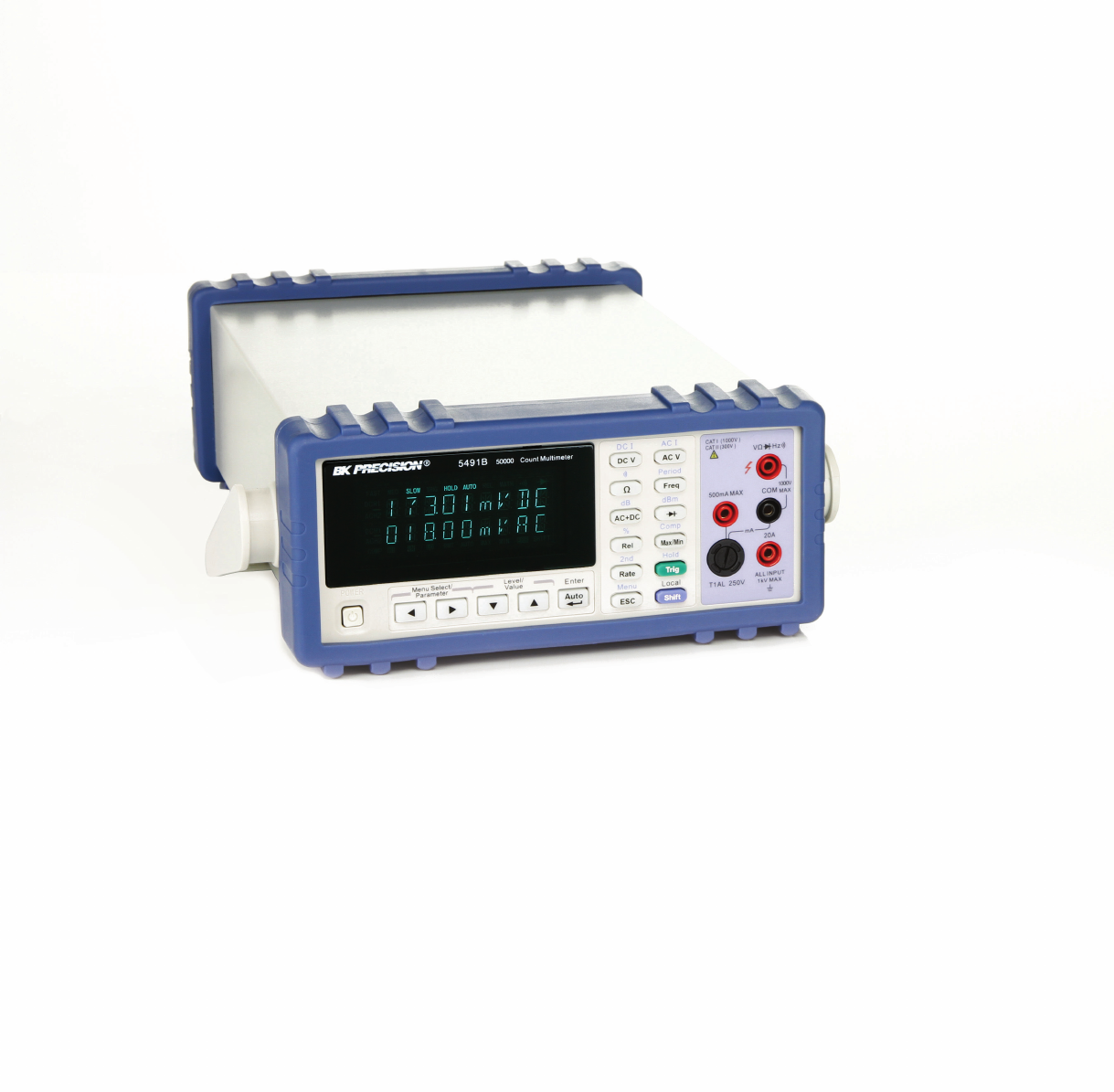
MULTIMETERS
Accurate and reliable measurements
60

Multimeters
Selection Guide
Display Counts
DCV Accuracy (%)
Analog Bar Graph
Auto/Manual Ranging
Manual Ranging
True RMS
Min/Max Hold
Peak Hold
Data Hold
Capacitance
Frequency
Logic Level
Transistor Gain (hfe)
Temperature
Relative Mode
dBm Measurement
Diode Test
Continuity Test
Max. Current Range (Amps)
Battery Life (Hours)
Auto Power off
PC Interface
Model
Page
20,000 0.03 √ √ √ √ √ √ √ √ √ 20 N/A N/A √2831E 62
50,000 0.02 √ √ √ √ √ √ √ √ √ 20 N/A N/A √5491B 62
120,000 0.01 √ √ √ √ √ √ √ √ √ 12 N/A N/A √5492B 62
2,000 1.2 √ √ √ 10 200 √ √ 2703C 63
2,000 1.2 √ √ √ √ √ 10 200 2408 64
2,000 0.8 √ √ √√√√√ √√ 10 150 √2704C 63
2,000 0.8 √√√ √√√√√ √√ 10 150 √2707B 63
2,000 0.5 √ √ √ √ √ √ √ 0.2 150 √ √ 2706B 63
2,000 0.5 √ √ √ 20 250 √ √ 2860A 64
3,200 1.2 √ √ √ √ √ 10 500 √2407A 64
3,400 1 √ √ √ √ √ √ 10 150 √ √ 2708B 63
4,000 1 √ √ √ √ 10 200 √ √ 2705B 63
4,000 0.5 √ √√√√√√ √√ 20 500 √ √ 388B 64
4,000 0.1 √√ √√√√√ √√ √√ 20 500 √ √ 390A 64
6,600 0.5 √ √ √ √ √ √ √ √ 10 150 √ √ 2709B 63
20,000 0.05 √ √ √ √ √ √ √ 20 500 √ √ 391A 64
40,000 0.1 √√ √√√√√√ √√ 10 150 √ √ 2712 63
60,000 0.08 √√ √√√√√√ √√ √√ 20 500 √ √ 393 64
2,000 N/A √ √ √ 600 1,000 √312B 64
2,000 0.5 √ √ √ √ 1,000 300 330B 64
4,000 0.5 √√ √√√√√√ √ √√2,000 100 √367A 64
4,000 0.5 √√ √√√√√√ √ √√1,000 100 √369B 64
10,000 1 √ √ √ √ √ 600 50 √313A 64
10,000 1 √ √ √ √ √ 100 45 √316 64
BenchClamp Meters Handheld
B&K Precision provides an extensive selection of multimeters. Our multimeters come in bench-top size for the engineering lab and handheld
size for portable use. For electricians, we oer a series of current clamp meters to measure high current and voltage with reliability and safety.
61
www.bkprecision.com
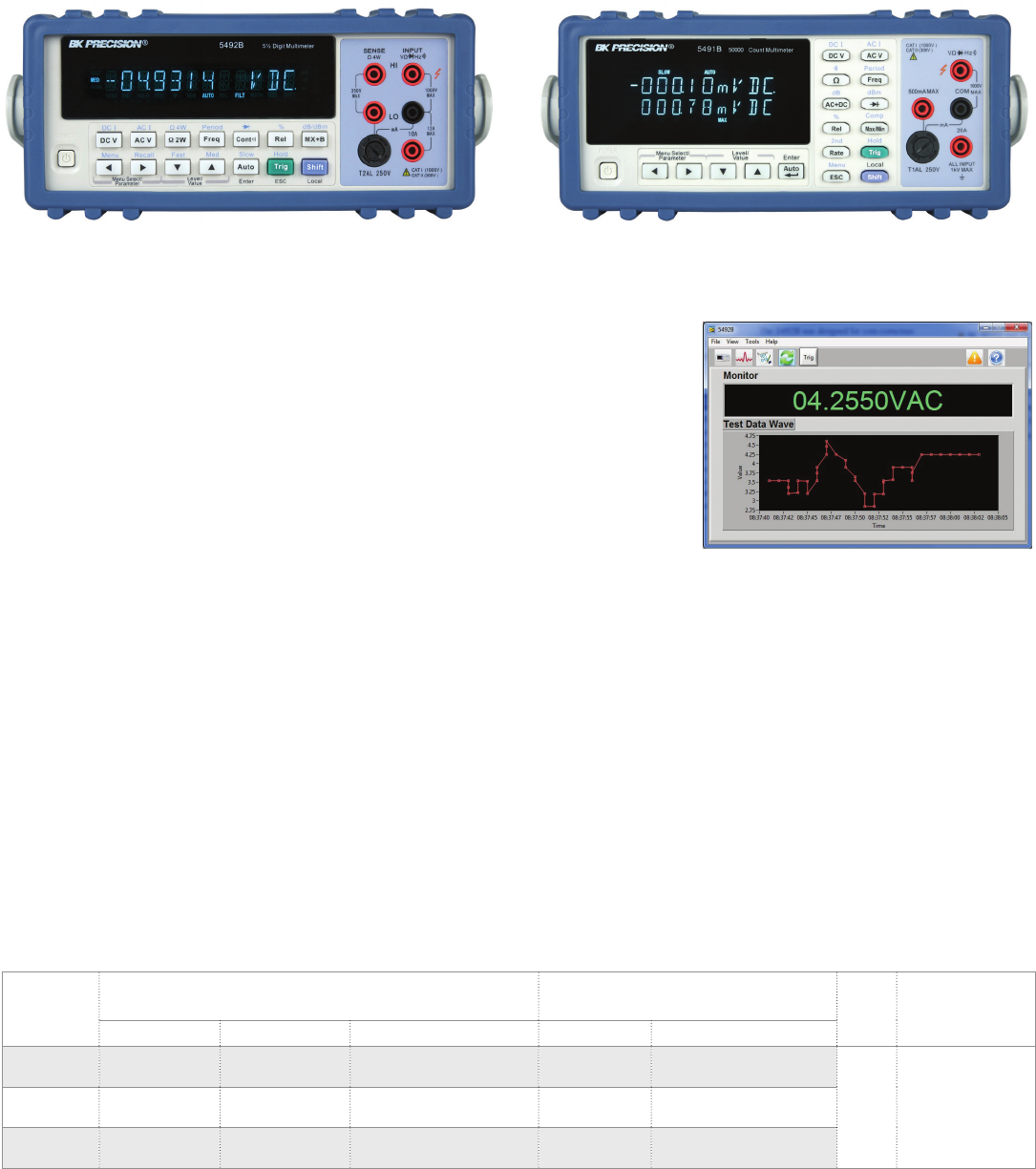
Multimeters
Bench DMM's
Features and Benefits
5½-digit, 120,000-count display resolution
0.01% basic VDC accuracy
Advanced triggering options such as
external, bus and event trigger
Two and four-wire resistance
measurement up to 120 MΩ
Limit mode for Pass/Fail testing
Built-in math functions: Rel, Max/Min,
dBm, dB, %, limits, Mx+B
CAT I (1000 V) / CAT II (300 V) protection
USB (Virtual Com), RS232 and
GPIB (option) interface
SCPI compatible
Features and Benefits
Up to 50,000 count display resolution
Basic VDC accuracy of 0.02% for the
5491B and 0.03% for the 2831E
Dual display to indicate two
measurements simultaneously
AC + DC True RMS
Up to 25 readings per second
measurement rate
Built-in math functions: Rel, Max/Min,
dBm, dB, %, Hold, Compare
CATI (1000 V)/CATII (300 V) protection
USB and RS232 (5491B only) interface
SCPI compatible
Specifications DC volts AC Volts Weight Dimensions
(W x H x D)
Ranges Resolution Basic accuracy Ranges Basic accuracy
2831E 200m V, 2 V, 20 V,
200 V, 1000 V
10 uV, 100 uV, 1 mV,
10 mV, 100 mV 0.03%(reading)+0.06%(range) 200 mV, 2 V, 20 V,
200 V, 750 V
0.4%(reading)+0.05%(range)
at 50-20 kHz, 2 V range
2.5 kg 225 ×100 × 355 mm5491B 500 mV, 5 V, 50 V,
500 V, 1000 V
10 uV, 100 uV, 1 mV,
10 mV, 100 mV
0.02%(read-
ing)+0.008%(range)
500 mV, 5 V, 50 V,
500 V, 750 V
0.35%(reading)+0.02%(range)
at 50-20 kHz, 5 V range
5492B 120 mV, 1.2 V, 12 V,
120 V, 1000 V
1 uV, 10 uV, 100 uV,
1 mV, 10 mV
0.01%(read-
ing)+0.004%(range)
120 mV, 1.2 V, 12
V, 120 V, 750 V
0.1%(reading)+0.1%(range) at
50 -20 kHz
5492B 5½-digit Multimeter
Model 5492B is a versatile 5½-digit,
120,000-count bench multimeter suitable for
applications in education, service, repair, and
manufacturing. This multimeter oers
powerful features not commonly found in
other 5½-digit DMMs such as advanced
triggering, buer storage operation, and a
GPIB interface option.
2831E 4 ½-digit and 5491B
50,000-count Multimeter
Bench Multimeters 2831E and 5491B provide
accurate and reliable measurements for
everyday use. These instruments measure
volts, ohms, and amps with great accuracy
and stability. Additionally, these meters
enhance productivity with built-in math
functions and USB connectivity for
remote controllability.
PC Connectivity (all models)
Programmable via USB, RS232, and GPIB
(5492BGPIB only) interface using industry
standard SCPI commands, these multimeters
can be remotely controlled and configured
from a PC. The multimeter can also be
remotely controlled using application
soware (via USB & RS232), which supports
front panel emulation and data logging of
measurement results.
62
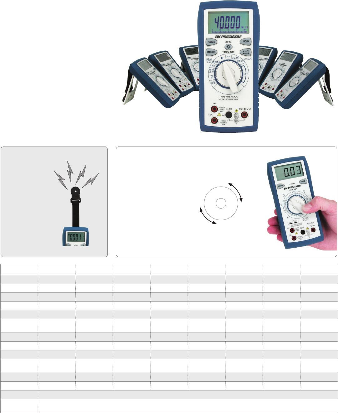
Multimeters
Handheld DMM's
Common Features & Benefits
DC voltage measurement up to 1000 V
AC voltage measurement up to 750 V
DC current measurement up to 10 A
Diode and continuity test
Drop resistant case
Magnetic hanging strap
Magnetic Hanging Strap
The ergonomic design allows
both le and right handed
users to rotate the knob while
holding the meter in one hand.
While one hand keeps the probe
on the circuit, the other hand
changes the meter’s function.
This speeds up troubleshoot-
ing because you don’t have to
locate the probe point in the
circuit again.
This convenient
feature lets you
hang your DMM
on any magnetic
metallic surface,
freeing up your
hands for
troubleshooting.
Specifications 2703C 2704C 2705B 2706B 2707B 2708B 2709B 2712
Ranging Manual Manual Auto/Manual Manual Manual Auto/Manual Auto/Manual Auto/Manual
True RMS - - - - AC AC AC AC + DC
Current 10 A DC 10 A AC/DC 10 A AC/DC 200 mA AC/DC 10 A AC/DC 10 A AC/DC 10 A AC/DC 10 A AC/DC
Capacitance -to 20 uF -to 20 mF to 20 uF -to 66 mF to 40 uF
Transistor test - √ - - √ - - -
Frequency
counter -to 20 MHz -to 40 kHz to 20 MHz -to 66 MHz to 500 kHz
Temperature ---√----
Logic probe - √ - - √ - - -
Backlight LCD - - - √ - - √ √
Analog bar
graph - - - - - √ - √
Battery test √-------
Auto power o √ - √ √ - √ √ √
Weight 283 g
Dimensions
(W x H x D) 78 x 163 x 42 mm
Single-handed Operation
B&K Precision’s 2700 Tool Kit® Series
These meters are excellent for most jobs
that require flexibility, accuracy, and speed.
Value-packed features make these meters a
must for everyone’s “Tool Kit®”.
63
www.bkprecision.com
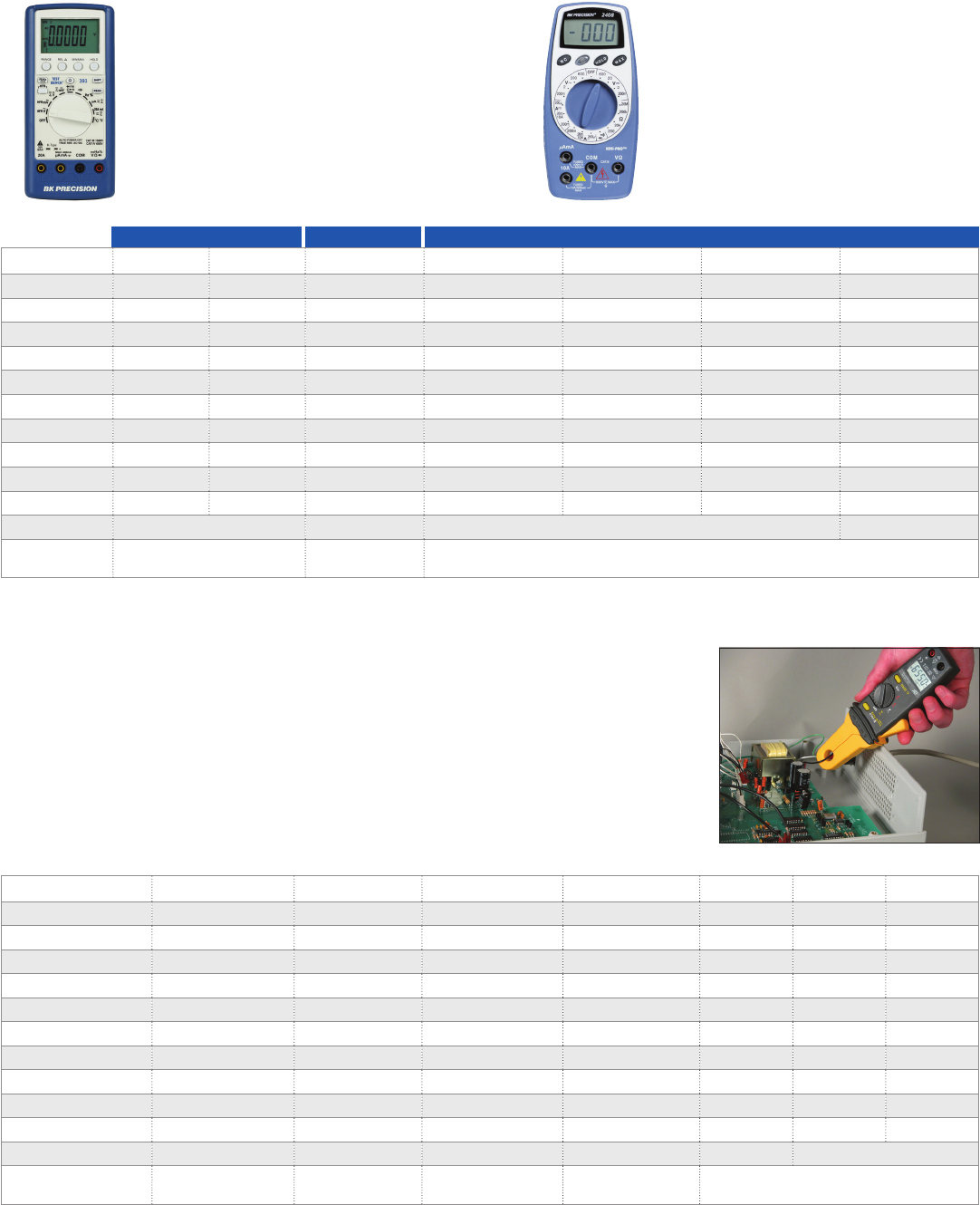
Multimeters
Digital Handheld & Clamp-on
The Mini-Pro® Series oers the hobbyist a
good choice for performing 90% of most
basic electrical measurements such as
DC/AC voltage, DC current, and
resistance. Compact in size and low in
cost, these meters are great to have in
every toolbox and field service kit.
The Test Bench® Series are high
performance and value-priced, portable
multimeters, oering more features for the
dollar than other multimeters. These meters
measure resistance, capacitance, frequency,
and temperature. This series also includes a
logic indicator and component test function.
Specifications 2408 2407A 2860A 388B 390A 391A 393
Display counts 2,000 3,200 2,000 4,000 4,000 20,000 60,000
Basic DC accuracy 1.2% 1.2% 0.5% 0.5% 0.1% 0.05% 0.08%
Ranging Manual Auto Manual Manual Auto/Manual Manual Auto/Manual
Current 10 A 10 A 20 A 20 A 20 A 20 A 20 A
USB - - - - √ - √
Bar graph - √ - - √ - √
Auto Power O - √ √ √ √ √ √
Continuity √ √ √ √ √ √ √
Data hold √ √ - √ √ √ √
Max. hold √ - - - √ - √
Weight 206 g 353 g 320 g 400 g
Dimension
(W x H x D) 57 x 143 x 35 mm 89 x 175 x 38 mm 89 x 198 x 40 mm
Clamp-on Meters
B&K Precision oers a variety of current
clamps from small to large, for safe
non-invasive current measurements. These
meters also measure voltage and resistance.
Some models even support frequency and
capacitance measurements, and include
special features such as recording capabilities
of minimum and maximum values, peak
values, and diode testing.
Common Features & Benefits
AC voltage and current measurements
Resistance measurements
Audible continuity
Data hold
Low battery indicator
Overload protection
CE mark
Mini-Pro® Survivor® Test Bench®
Specifications 316 312B 313A 330B 350B 369B 367A
Display counts/digits 10,000 2,000 10,000 2,000 A 3,200 4,000 4,000
True RMS - - - - - √ √
AC current 100 A 600 A 600 A 1,000 A 1,000 A 1,000 A 2,000 A
DC current 100 A -600 A - - 1,000 A 2,000 A
AC voltage 600 V 600 V 600 V 750 V 750 V 750 V 750 V
DC voltage 600 V -600 V 1,000 V 1,000 V 1,000 V 1,000 V
Resistance 10 kΩ 200 Ω 1,000 Ω 2,000 MΩ 30 MΩ 40 MΩ 40 MΩ
Frequency - - - - √ √ √
Continuity √ √ √ √ √ √ √
Capacitance - - - - - √ √
Weight 180 g 210 g 220 g 482 g 482 g 482 g
Dimensions 70 x 202 x 34 mm 50 x 187 x 29 mm 70 x 192 x 34 mm 91 x 274 x 43 mm 91 x 274 x 43 mm
64
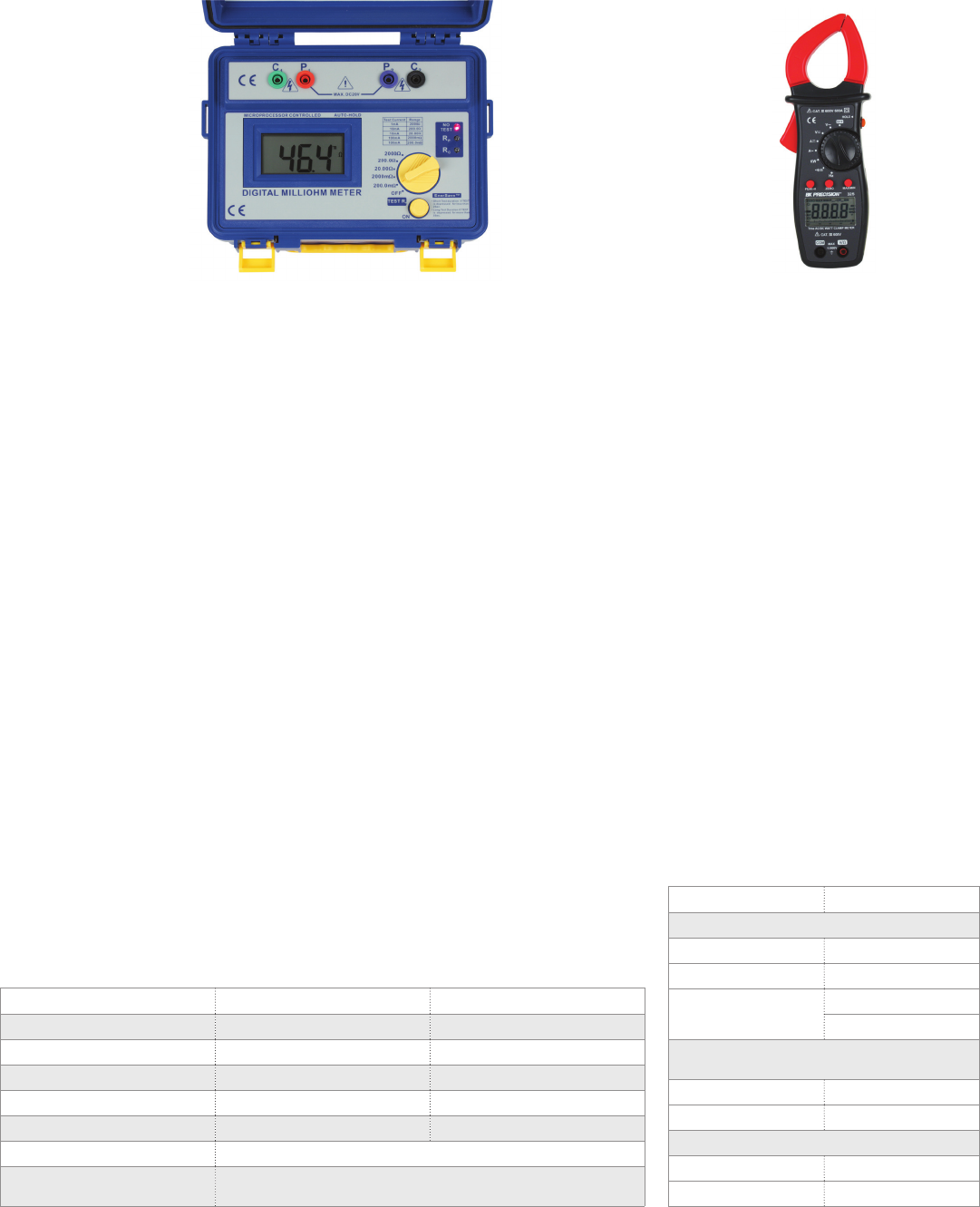
Electrical Testers
302 Phase and Motor
Rotation Meter
The 302 is a 3-phase presence and rotation
meter combined with a 3-phase motor
rotation tester. It provides the quickest and
easiest means for servicing and repairing
3-phase systems and 3-phase
rotating machinery.
307A & 308A Insulation Tester
The battery-powered insulation testers
models 307A and 308A are intended
primarily for periodic testing of industrial
motors, transformers, electrical wiring, and
cable insulation. Low readings may point
to insulation deterioration that can indicate
impending failure.
Features & Benefits
Selectable 250 V, 500 V, or 1000 V
insulation test
Low resistance test
Extra rugged integral carrying case
Live circuit indicator warns of
safety hazard
IEC / 61010-1 CAT III 600V / CE
325 True RMS AC/DC Power
Clamp Meter
The 325 AC/DC true RMS power clamp meter
provides safe, non-invasive measurements of
up to 400 kW, 400 A AC, and measures up to
600 V AC/DC utilizing the pair of standard
test leads. The lightweight, portable,
battery-powered clamp meter measures
parameters needed to troubleshoot
residential and small commercial electrical
systems such as ACV, DCV, ACA, DCA, Ω, W,
frequency and continuity.
Features & Benefits
3 ¾ digit backlit LCD display
Auto range
Auto power o
Data hold
High speed digital bargraph
Jaw opening (35 mm)
IEC / 61010 CAT III 600 V / CE
Specifications 307A 308A
Type Analog Digital
Output voltage 1,000 VDC 1,000 VDC
Maximum current 1.3 mA 1.2 mA
Resistance range 0-400 MΩ 0-2,000 MΩ
Center scale 1 MΩ, 2 MΩ, 4 MΩ Does not apply
Weight 925 g with batteries
Dimensions
(W x H x D) 180 x 220 x 90 mm
309 Digital Earth Resistance Meter
The 309 digital earth resistance meter (also
known as an earth ground meter) is a small,
compact, battery-powered, professional
meter that is easy-to-use and invaluable
to electricians and contractors who need
to ensure the "ground" quality and
eectiveness of buildings, structures,
equipment or electrical systems. A good earth
ground is required for new buildings
or structures needing to pass required
electrical codes. Older buildings can lose a
good eective earth ground connection over
time or aer being struck by lightning.
310 Digital Milli-ohm Meter
The 310 digital milli-ohm meter is used to
ensure continuity and integrity of a wire,
cable, conduit, or any electrical connection.
The 310 has a display resolution of 100 µΩ
and include a professional 4-wire Kelvin test
lead set to ensure accurate readings. The
heavy duty case comes with a convenient
shoulder strap and has a rubber seal to make
the unit water resistant.
Specifications 325
DC current
Range 400 A, 600 A
Resolution 0.1 A, 1 A
Accuracy 1.5% + 5 digits
2% + 5 digits
AC current (True RMS : From 10% to
100% of range)
Range 400 A, 600 A
Resolution 0.1 A, 1 A
Accuracy
40 Hz- 65 Hz 2.0% + 5 digits
65 Hz - 1 kHz 3.0% + 8 digits
Model 310 Model 325
65
www.bkprecision.com
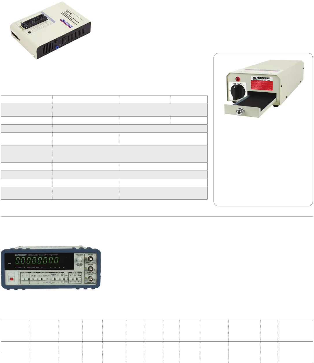
Device-Programmers & Counters
66
Universal device programmers are powerful,
versatile, and simple to use. Our programmers
are the ideal solution for programming new
chips as well as copying chips for backup or
repair purposes.
We oer on-going program soware updates
that extend device libraries and provide
continuous improvements for both models
844USB and 866C programmers. Whether you
are working with PLCC, SOIC, TSOP, DIP, TQFP,
SSOP, PSOP or QFP packaging, we provide an
extensive line of socket adapters that will work
in conjunction with our programmers.
Common Features & Benefits (EPROM)
Extensive device libraries
Fast and high performance
Powerful program soware
Supports Windows® 10
Deluxe EPROM Eraser
The model 851 is a heavy duty EPROM
eraser that can simultaneously erase up
to 40 twenty-four pin EPROM chips. It is
constructed of an all-metal case, and is
designed with a chip drawer that protects
the user from UV radiation exposure. The
drawer is lined with conductive foam to
prevent electrostatic damage to the chips.
A 30-minute timer is provided to control
timing of UV exposure.
844USB, 866C & 867 EPROM Programmers
Specifications 844USB 866C 867C
Devices supported EPROM, EEPROM/Flash, Serial EPROM, Microcontroller,
PLD and Bi-Polar PROM (Bi-Polar PROMs 866C, & 867C)
Device libraries over 32,900 over 88,000 over 90,000
Interface USB 2.0 / USB 1.1 compatible
Programming socket DIL40 pin ZIF socket,
ISP for in-circuit programming DIL48 pin ZIF socket,
ISP for in-circuit programming
Buer features Erase, Random Data Fill, Fill Block, Copy Block, Move Block, Swap Block,
Buer Print, Find Text, Replace Text, GoTo Address,
Checksum Calculator, 8 bit & 16 bit View Modes
I.C. tester No Yes
Power requirements 100-240 VAC, 47-63 Hz
Weight 500 g 0.9 kg
Dimensions
(W x H x D) 95 x 35 x 160 mm 140 x 56 x 195 mm
Windows® is a registered trademark of Microsoft Corporation in the United States and other countries.
Model 867C
1823A & 1856D Counters
The 1823A and 1856D are reciprocal 2.4 GHz and 3.5 GHz universal frequency counters that are
microprocessor controlled. Their LED displays can provide up to nine digits of resolution using an external
time base with a 10 s gate time. The high accuracy, sensitivity and versatility of these counters make them
an extremely valuable instrument to scientists, engineers, experimenters, and communications technicians
for a broad spectrum of laboratory and service applications.
Features and Benefits
±1 ppm Time base stability
Trigger level function (1823A only)
Frequency ratio measurement function
(1823A only)
Time interval measurement function (1823A only)
Specifications Range
Frequency,
Totalize,
Period
Time
Base
Stability
Best
Resolution
No. of
Digits
Display
Hold
Low
Pass
Filter
Remote
Interface
Time Interval
Measurement
Frequency
Ratio
Measurement
Weight Dimensions
(W x H x D)
1823A 0.1 Hz - 2.4 GHz
ñ1ppm 1 nHz 9 à à RS232
√ √
2.5 kg 239 x 89 x 269 mm
1856D 0.1 Hz - 3.5 GHz - -
RPM measurement function
(1856D only)
External frequency standard input
Bright LED display
Attenuator
RS232C Interface
Model 1823A
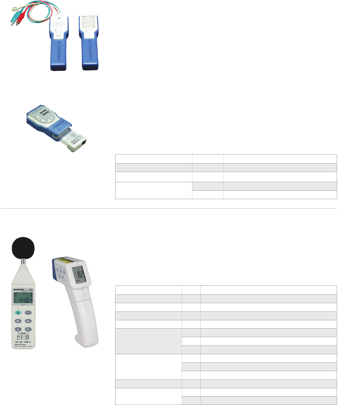
67
www.bkprecision.com
Video & Cable / Environmental Testers
1211E & 1257 NTSC Generators
Models 1211E and 1257 are handheld models that provide standard test patterns used to test
picture quality. These patterns include NTSC color bars, crosshatch, dot, staircase, circle,
center cross, windows, and a full range of color raster patterns.
262 Tone Generator & Cable Tracer Kit
The 262 kit comprises two handheld, battery-powered instruments designed to perform a
variety of tests on unenergized telephone lines or LAN cables. The tone generator has alligator
clips and a standard RJ11 plug, allowing the tone generator to be connected to stripped wires,
terminal panels, wall plates, or modular single line jacks. The cable tracer can trace the signal
from the tone generator signals through dry wall, wood, and many other non-metal surfaces to
help identify wires and their location without piercing the insulation.
231A Deluxe Multi-network Cable Tester
The 231A can easily read the correct pin configuration of 10BaseT cable (category 5), 100Ba-
seTx, 10Base2 cable (coax) and RJ45/RJ11 modular cables, 356A, TIA 568A, TIA 568B and Token
Ring cables by comparing one transmitting end to the corresponding receiving end. With the
remote kit, it can test cables installed far away either on wall plate or patch panel up to 1000
away. It is easy to verify the cable continuity, open, short, and cross connect, featuring auto or
manual scan for pin-out indicators.
Category Model Description
Network cable testers 231A Deluxe multi-network cable tester
Tone generator & cable tracer 262 Tone generator & cable tracer kit
NTSC Generators 1211E Handheld NTSC generator with audio output
1257 Portable NTSC generator with RF output
Model 262
Model 231A
Model 636Model 732A
Category Model Description
Air velocity meter 731A Anemometer with wand probe
Digital carbon monoxide meter 627 Carbon monoxide (CO) meter
Digital infrared thermometer 636 Non-contact infrared thermometer with laser pointer
Digital light meter 615 Light meter
Digital thermo-hygrometer
625 Thermo-hygrometer
720 Humidity/temp meter w/dual input
725 Datalogging humidity/temp meter w/dual input
Digital thermometer
630 Dual K-type thermometer
710 Temperature meter, dual input
715 Datalogging temperature meter, dual input
Sound level calibrator CAL73 Standard acoustic calibrator (94 dB, 1 kHz sine wave)
Sound level meter 732A Digital sound level meter with RS 232 capability
735 Datalogging digital sound level meter w/RS232 soware & cable
732A & 735 Sound Level meters
Two handheld meters that measure sound level from 30 to 130 dB with both A and C frequency
weighting. Both meters meet IEC 651 type II standards.
Digital Infrared Thermometer
Compact, handheld infrared digital thermometers with laser pointer and adjustable emissivity
designed for simple one-hand operation. These meters make non-contact temperature
measurements and display the values in both ºF and ºC.
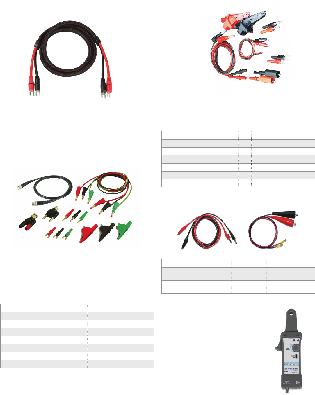
General Accessories
Power Supply & Oscilloscope Probes
CP62 300 kHz AC/DC Oscilloscope
Current Clamp Probe
The CP62 current probe allows a general purpose
oscilloscope to display AC and DC current signals up to
100 A Peak (70 A RMS). The CP62 current probe can also
make AC and DC measurements with a multimeter by using
the recommended accessory TL62 (BNC-to-banana)
plug adapter.
Description Qty. IEC rating Max current
Retractile lead, 100 cm *3 600 V CAT II 36 A
6/4mm spade lug adapter *3 33 Vdc/ 70 Vac 36 A
BNC cable assembly, 100 cm 1500 Vrms 3 A
BNC female to double banana plugs 1500 Vrms 3 A
Banana plug adapter *3 33 Vdc/ 70 Vac 36 A
BNC male to double binding posts 1500 Vrms 3 A
Insulated alligator clip *3 600 V CAT IV 36 A
*Colors: Black, red & green
High capacity retractable sheath silicone jacketed leads
Extra-large insulated alligator clips
Black, red and green components
Storage case
TLPWR1 High Current Premium Test Lead Accessory
High quality red and black cable with externally braided wrap with large
fork-type spade connectors for connecting to high current power supplies
or DC loads.
Length: 2 m
Rated current: 60 A
Gauge: 8 AWG
Connector inner diameter: 8 mm (approximate)
Connector outer width: 15 mm (approximate)
Wire material: flexible silicon jacket
Description Qty. IEC Rating Max current
Retractile leads, 120cm *2 600 V CAT II 25 A
6/4mm Spade lug adapters *2 33 VDC/ 70 VAC 36 A
Standard alligator clips *2 300 V CAT I 3 A
4mm Banana plug adapters *2 33 VDC/ 70 VAC 36 A
Insulated alligator clips *3 600 V CAT IV 36 A
Sense lead pair, 1 m *1 33 VDC/ 70 VAC 3 A
TLPS Power Supply Accessory Kit
This accessory kit combines safety and functionality. A must have for anyone who
uses a power supply, this kit is ideal for use with power supplies in educational,
service and maintenance, and manufacturing applications.
Carrying Cases
*Colors: Black & Red
TL 5A & TL 30 Power Supply Leads
Description Qty. IEC rating Max current Model
Leads, 4 mm banana plug
leads, 100 cm *2 33 VDC/ 70 VAC 5 A TL 5A
Cables, #10 lug to battery
clip, 75 cm *2 33 VDC/ 70 VAC 30 A TL 30
TL 5A TL 30
50 mA to 100 Apk
DC to 300 kHz
Medium and large insulated alligator clips
Black and red components
Sense lead included
CC545 General Purpose Power Supply Accessory Kit
This kit provides everything needed to put a bench power supply to work. The kit
includes 3 high capacity test leads with retractile sleeve plugs. Rated at 600 V
CAT II and 36 A, the leads provide safe connection to either standard or sheathed
jacks while its silicone jacket wire stays flexible under all conditions.
*Colors: Black & Red
68
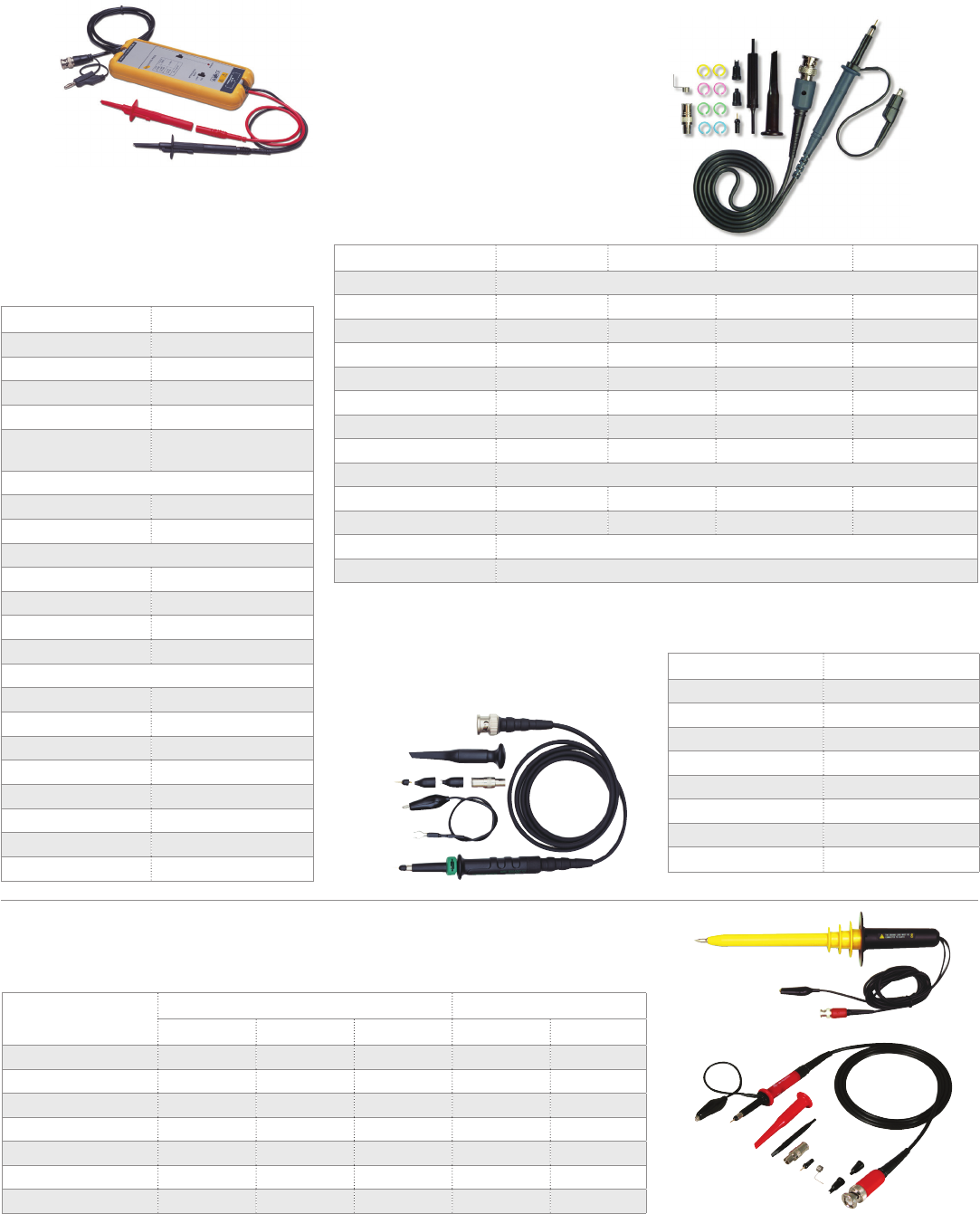
www.bkprecision.com
General Accessories
Oscilloscope Probes
Applications
Switching power supply designs
Motor drive design
Electronic ballast design
Specifications PR-60
Bandwidth 25 MHz (-3 dB)
Attenuation ratio x10/x100
Accuracy ±2%
Rise time 14 ns
Input impedance 4 MΩ/10 pF each side
to ground
Input voltage
Max. dierential ±700 V (DC+Peak AC)
Max. common mode ±700 V (DC+Peak AC)
Output voltage
Max. amplitude ±7 V (into 2 kΩ load)
Oset (Typical) ≤±5 mV, -10°to 40° C
Noise (Typical) 1.5 to 2 mV
Source impedance 1 Ω @ 1 kHz 8 Ω @ 1 MHz
CMRR
50Hz 86 dB
20kHz 66 dB
200kHz 56 dB
Probes Sprung hooks (B/R)
Length of input lines 45 cm
Operating temperature 14° to 104°F (-10° to 40°C)
Power requirements 4 x AA batteries
Certification IEC61010-1 CATIII
General Purpose Passive Probes
This full line of probes increases the versatility of your oscilloscope with both fixed and switchable attenuation.
Each probe includes a full accessory kit with a sprung hook, replacement tip and BNC adapter. All models are
compliant to IEC61010-031.
Specifications Passive probes High voltage (passive)
PR 33A PR 37 AG PR 37AR PR 100A PR-55
Bandwidth (MHz) 15/90 6/150 6/150 250 50
Attenuation x1/x10 x1/x10/REF x1/x10/REF x100 x1000
Input impedance R(MΩ) 1/10 1/10 1/10 100 100
Capacitance (pF) 46/16 100/15 100/15 6.5 1
Voltage (VDC+AC max) 600 600 600 1,200 10,000
Compensation (pF) 10-35 10-35 10-35 10-35 10-30
Cable length 1.2 m 1.2 m 1.2 m 1.2 m 2.0 m
Model PR-55
Model PR 37AR
PR 32A RF Detector Probe Specifications PR 32 A
Bandwidth 100 kHz - 950 MHz
Accuracy ±3 dB
Voltage 200 V
HF voltage 50 Ve
Actuating Voltage 250 mV
Input capacitance 5 pF
Cable length 1.2 m
Body color Black
Specifications PR150B PR250B PR500B PR2000B
Type 5 mm Passive Voltage
Bandwidth 17/150 MHz 250 MHz 500 MHz 200 MHz
Attenuation 1x/10x 10x 10x 100x
Input impedance 1/10 MΩ 10 MΩ 10 MΩ 100 MΩ
Input capacitance ≈45/12 pF ≈12 pF ≈10 pF ≈5 pF
Rise time 20/2.3 ns 1.4 ns 0.7 ns 1.8 ns
IEC rating 300 V CAT II 300 V CAT II 300 V CAT II 2,000 V CAT I
Compensation 10−30 pF 10−30 pF 6–22 pF 10−30 pF
Cable length 1.2 m
Attenuation accuracy - - - 6%
Voltage coeicient (VCR) - - - ≤30 ppm/V
Operating temperature 0° to +50° C
Humidity 85% RH or less (at 35° C)
PR-60 Active
Dierential Probe
Allows for safe and accurate floating measurements
with your standard analog or digital oscilloscope.
Passive Oscilloscope Probes
High bandwidth, high impedance 10x passive voltage
probe with 10 MΩ input impedance. All probes are
RoHS (2002/95/EC) compliant.
69
General Accessories
Signal Interconnect Kits
Description Qty. Frequency
range Max. VSWR
BNC cable assembly, 100 cm 2DC - 1 GHz 1.20:1 @ 1 GHz
BNC feed-thru terminator, 2 W 1DC - 1 GHz 1.20:1 @ 1 GHz
BNC tee, female-male-female 1DC - 4 GHz N/A
BNC female to double banana plugs 2N/A N/A
BNC female to N type male 1DC - 4 GHz 1.30:1 @ 4 GHz
BNC female to N type female 1DC - 4 GHz 1.30:1 @ 4 GHz
BNC attenuator, 20 dB (10x) 2 W 1DC - 4 GHz 1.25:1 @ 4 GHz
TLFG Function Generator Accessory Kit
The kit provides convenience and functionality to get a user up and running quickly.
The kit eliminates the time consuming start-up task of collecting cables and adapters.
Description Qty. Frequency
range Max. VSWR
BNC cable assembly, 120 cm 2DC - 1 GHz 1.20:1 @ 1 GHz
BNC (f) breakout w/miniature
alligator clips 1DC - 1 GHz N/A
BNC (f) breakout w/Ø.031 sockets 1DC - 1 GHz N/A
MiniFlex IC clips, black & red pair *2 N/A N/A
MicroFlex IC Clips, black & red pair *2 N/A N/A
BNC tee, female-male-female 1DC - 4 GHz N/A
BNC female to N type male 1DC - 4 GHz 1.30:1 @ 4 GHz
Description Qty.
Universal adapters 6
BNC male adapters 2
BNC female adapters 2
F male adapter 1
F female adapter 1
N Type male adapters 2
N Type female adapters 2
RCA male adapter 1
RCA female adapter 1
SMA male adapter 1
SMA female adapter 1
TNC male adapters 2
TNC female adapters 2
UHF male adapters 2
UHF female adapters 2
Mini-UHF male adapter 1
Mini-UHF female adapter 1
Convenient interconnection kit
BNC, TNC, N, SMA, RCA, F, SMA &
Mini-UHF connectors
Tarnish resistant nickel finish
Gold plated center contacts
Zippered storage case
12-piece kit
BNC & N type 50 Ω connectors
Gold plated center contacts
Storage case
Description Qty. Frequency
range Max. VSWR
BNC tee female-male-female 1DC - 4 GHz N/A
N type female-female 1DC - 8 GHz 1.30:1 @ 8 GHz
N type male-male 1DC - 8 GHz 1.30:1 @ 8 GHz
N type tee female-male-female 1DC - 8 GHz N/A
BNC female to N type male 1DC - 4 GHz 1.30:1 @ 4 GHz
BNC male to N type female 1DC - 4 GHz 1.30:1 @ 4 GHz
BNC female-female 1DC - 4 GHz 1.30:1 @ 4 GHz
BNC male-male 1DC - 4 GHz 1.30:1 @ 4 GHz
BNC female to N type female 1DC - 4 GHz 1.30:1 @ 4 GHz
BNC Tee female-female-female 1DC - 4 GHz N/A
N type tee female-female-female 1DC - 8 GHz N/A
N type right-angle male-female 1DC - 8 GHz 1.35:1 @ 8 GHz
CT 2701 General Purpose Universal Coaxial Adapter Kit
This kit provides a convenient solution for most interconnection needs. The
included 6 universal adapters allows assembly of hundreds of dierent
configurations: male-to-male, female-to-female, male-to-female, in-series and
between-series for BNC, TNC, N-Type, F, RCA, SMA, UHF and Mini-UHF.
CC 510 General Purpose Function Generator Kit
This kit provides a range of BNC and N Type coaxial interconnection for basic
function / arbitrary waveform generators use. All components feature standard
BNC or N Type interfaces with 50 Ω impedance and gold plated center contacts
to ensure accurate repeatable measurements. The kit is provided in a convenient
foam lined storage case for easy selection and use.
*black & red pair
CC500 General Purpose BNC &
N Type Adapter Kit
This general purpose BNC & N type adapter
kit provides a comprehensive range of
in-series and between-series BNC and N
type coaxial adapters for basic RF testing
and troubleshooting needs.
70
www.bkprecision.com
General Accessories
Multimeters
Specifications PR 28A
Attenuation x1000
Voltage (AC) 20 kV
Voltage (DC) 40 kV
Bandwidth 60 Hz
Input impedance 1000 MΩ
Accuracy (AC & DC) ±3%
Cable length 1.2 m
Description TL-50B
4 mm straight to
right-angle
silicone leads, 1.5 m
1000 V CAT III 12 A
Probe bodies w/Ø2
mm tip 1000 V CAT III 36 A
Pincer style clips 1000 V CAT III 6 A
Alligator clips 300 V CAT I 3 A
Spade lug adapters 42 V
(1000 V) -36 A
Banana plug adapters 42 V
(1000 V) -36 A
Fully insulated
alligator clips 1000 V CAT III 20 A
TL 8 Surface Mount Tweezers
Two conductor leads
400 Vrms, 1 A
TL500B High Performance Bench DMM
Accessory Kit
Qty. Description Color
(4) Test lead 4 mm sheathed P-RaP
silicon 0.75, 100 cm
(2) black,
(2) red
(2) Spring tip MiniPRO - 4 mm jack (1) black,
(1) red
(1) Insulated BNC male
adapter - 4 mm safety jacks -
(2) Adapter - 4 mm banana plug
to jack
(1) black,
(1) red
(2) MiniFlex clip - 4 mm
jack-silicon 0.40, 10 cm
(1) black,
(1) red
(2) Adapter 6 mm spade
4 mm jack
(1) black,
(1) red
(2) Lead MiniPRO-J-PVC 0.40, 10 cm (1) black,
(1) red
(1) Tweezer test lead
set- 4 mm P, w/PVC pouch -
TL37 Red and Black CAT III 1000 V (CAT IV
600 V) Test Leads
Right angled sheathed banana replacement 10A test
leads for digital multimeters. With tip cap on, they are
rated to CAT III 1000V, CAT IV 600V, with tip cap o, they
are CAT II 1000V.
Description TL 130B
4 mm straight to
right-angle
silicone leads, 1.5 m
1000 V CAT III 12 A
Probe bodies w/Ø2mm
tip 1000 V CAT III 36 A
Alligator style clips 1000 V CAT III 20 A
Alligator clips 300 V CAT I 3 A
Specifications CP 3
(Accuracy specified at 18° to 28°C)
Current range 2 A to 400 A, DC or AC
Frequency Response (AC) 50 Hz - 400 Hz
Accuracy ±(2% reading + 2 A)
Input resistance 10 kΩ min.
Maximum conductor size 30 mm
Power requirement 9 V battery, NEDA 1604
Battery life 100 hr typical
Operating temperature 0° to 40°C, <70% RH
Storage temperature -20° to + 70°C, <80% RH
PR 28A 40 kV High Voltage DMM Probe
For voltage measurements above the specifications of
general purpose probes.
This kit of accessories was assembled to facilitate
requirements by high-performance bench digital
multimeters (DMMs) users. All the most popular
accessories in one kit. The kit oers MiniProbe test
probe, with spring-loaded tips for fine probing;
MiniPRO and MiniFlex test clips for small and micro
connections; and for those larger test points, both
spade lug and banana plug adapters, two pairs of test
leads for 4-wire measurements or calibration hookups,
an insulated BNC male to sheathed banana jack
adapter, and an insulated SMD tweezer set for
surface-mount component testing.
Silicone jacketed test lead wire
MiniProbe w/spring loaded stainless steel tips
Packaged in plastic case
RoHS (2002/95/EC)
IEC61010-2-031 compliant
Silicone lead wire length (1.5 m)
Tri-fold velcro pouch
TL 130B General Purpose DMM Kit
If you need only one basic accessory kit for your meter,
this is the one. Attach probes or clips to the sheath
plug to complete your test. So, flexible silicone leads
make movement easy. Kit is voltage and current rated
for electronic or electrical applications.
IEC61010-031 compliant
Silicone lead wire length (1.5 m)
Tri-fold velcro pouch
TL-50B Maxi-Pro DMM Kit
Complete accessory kit for all your testing
needs. Includes so, flexible silicone lead wire
for easy movement.
CP3 DC/AC Current Clamp
Converts any DMM to a current clamp
Measures current without disconnecting circuit
under test
Measures to 400 A DC or AC
Outputs 1 mV per Amp, operates on 2 V range
of any DMM
71
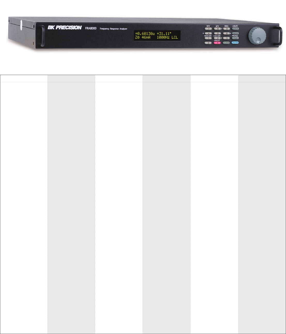
72
231A .......................... 67
262 ............................ 67
307A .......................... 65
308A .......................... 65
312B .................... 61,64
313A ..................... 61,64
316 ............................ 64
325 ............................ 65
367A ..................... 61,64
369B .................... 61,64
388B .................... 61,64
390A ..................... 61,64
391A ..................... 61,64
392 ............................ 64
393 ............................ 64
570A ..................... 39,43
575A ..................... 39,43
600B ......................... 45
601B ......................... 45
615 ............................ 67
625 ............................ 67
627 ............................ 67
630 ............................ 67
636 ............................ 67
710 ............................ 67
715 ............................ 67
720 ............................ 67
725 ............................ 67
731A .......................... 67
732A .......................... 67
735 ............................ 67
810C .................... 39,43
815 ............................ 43
830C .................... 39,43
844USB ..................... 66
866C ......................... 66
867C ......................... 66
875B .................... 39,42
878B .................... 39,42
879B .................... 39,42
880 ............................ 42
881 ............................ 43
885 ............................ 42
886 ............................ 42
889B .................... 39,41
890C .................... 39,43
891 ............................ 41
894 ............................ 40
895 ............................ 40
1211E ........................ 67
1257 .......................... 67
1513 .......................... 18
1514 .......................... 18
1550 .......................... 17
1621A ........................ 17
1623A ........................ 17
1627A ........................ 17
1651A ........................ 18
1652 .......................... 18
1653A ........................ 21
1655A ........................ 21
1665 .......................... 17
1666 .......................... 17
1667 .......................... 17
1670A ........................ 18
1671A ........................ 18
1672 .......................... 18
1673 .......................... 18
1680 .......................... 17
1682A ........................ 17
1685B ....................... 14
1686A ........................ 17
1687B ....................... 14
1688B ....................... 14
1692 .......................... 17
1693 .......................... 17
1694 .......................... 17
1696 .......................... 16
1697 .......................... 16
1698 .......................... 16
1710A ........................ 17
1715A ........................ 17
1730A ........................ 17
1735A ........................ 17
1737 .......................... 13
1739 .......................... 16
1747 .......................... 13
1760A ........................ 18
1761 .......................... 18
1762 .......................... 18
1785B ....................... 14
1786B ....................... 14
1787B ....................... 14
1788 .......................... 14
2120C .................. 31,37
2125C .................. 31,37
2160C .................. 31,37
2190E ................... 31,37
2407A ................... 61,64
2408 .......................... 64
2511 .......................... 36
2512 .......................... 36
2515 .......................... 36
2516 .......................... 36
2540C ............. 31,33-34
2544C ....................... 34
2550 .......................... 31
2552 ..................... 35,50
2553 ..................... 35,50
2554 ..................... 35,50
2555 ..................... 35,50
2556 ..................... 35,50
2557 ..................... 35,50
2558 ..................... 35,50
2559 ..................... 35,50
2560 .......................... 31
2563 .......................... 32
2565 .......................... 32
2566 .......................... 32
2567 .......................... 32
2568 .......................... 32
2569 .......................... 32
2650A ................... 58-59
2652A ........................ 58
2703C ....................... 12
2704C ....................... 12
2705B ....................... 12
2706B ....................... 21
2707B ....................... 21
2708B ....................... 21
2709B ....................... 19
2712 ..................... 61,63
2831E ........................ 19
840 .......................... 44
2841 ..................... 39,44
2860A ........................ 67
3001 ..................... 49,56
3003 ..................... 49,56
4001A ........................ 49
4003A ................... 49,56
4005DDS .............. 49,54
4007B .................. 49,54
4010A ................... 49,56
4011A ................... 49,56
4012A ................... 49,56
4013B .................. 49,54
4014B .................. 49,54
4017A ................... 49,56
4030 ..................... 49,56
4033 ..................... 49,52
4034 ..................... 49,52
4040A ................... 49,56
4040B ....................... 54
4045B .................. 50,54
4047B .................. 49,53
4053B .................. 49,53
4054B .................. 49,53
4055B .................. 49,53
4063 ..................... 49,52
4064 ..................... 49,52
4065 ..................... 49,52
4075B ....................... 49
4076B .................. 49,51
4077B .................. 49,51
4078B .................. 49,51
4079B ..................49, 51
4080B ..................49, 51
5335B ....................... 20
5491B ....................... 61
5492B ....................... 62
8500 ..................... 23,29
8502 .......................... 29
8510 .......................... 29
8512 .......................... 29
8514 .......................... 29
8518 .......................... 29
8520 .......................... 29
8522 .......................... 29
8524 .......................... 29
8526 .......................... 29
8540 ..................... 23,29
8600 ................ 23,26,45
8601 .......................... 26
8602 .......................... 26
8610 .......................... 26
8612 .......................... 26
8614 ..................... 26,27
8616 .......................... 26
9103 .......................... 13
9104 .......................... 13
9110 .......................... 18
9111 .......................... 18
9115 ..................... 10,45
9115-AT .................... 10
9116 .......................... 10
9117 .......................... 10
9120A ........................ 15
9121A ........................ 15
9122A ........................ 15
9123A ........................ 15
9124 .......................... 15
9129B ....................... 11
9130B ....................... 11
9131B ....................... 11
9132B ....................... 11
9151 .......................... 13
9152 .......................... 15
9171B ......................... 6
9172B ......................... 6
9173B ......................... 6
9174B ......................... 6
9181B ......................... 6
9182B ......................... 6
9183B ......................... 6
9184B ......................... 6
9201 .......................... 12
9202 .......................... 12
9205 .......................... 12
9206 .......................... 12
9801 .......................... 21
9803 .......................... 21
9805 .......................... 21
9832 .......................... 19
9833 .......................... 19
BA6010 ................ 45,46
BA6011 ................ 45,46
CAL73 ....................... 67
CC500 ....................... 70
CC510 ....................... 70
CC545 ....................... 68
CP3 ........................... 71
CP62 ......................... 68
CT2701 ..................... 70
DP21 ......................... 39
DP31A .................. 39,43
DP52 .................... 39,43
FRA8000 .............. 45,47
MDL200 ................ 24-25
MDL252 ................ 24-25
MDL302 ................ 24-25
MDL305 ................ 24-25
MDL400 ................ 24-25
MDL505 ................ 24-25
MDL600 ................ 24-25
PR100A ..................... 69
Index
PR 28A ...................... 71
PR 32 A ..................... 69
PR 33 A ..................... 69
PR 37 AG ................... 69
PR 37 AR ................... 69
PR-55 ........................ 69
PR-60 ........................ 69
PR150B ..................... 69
PR200B ..................... 69
PR250B ..................... 69
PR500B ..................... 69
PR2000B ................... 69
PVS10005 ................. 69
PVS60085 ................. 69
PVS60085MR ............ 69
SDL-1000-25 ............. 28
SDL-1000-50 ............. 28
SDL-600-150 ............. 28
SDL-600-300 ............. 28
SDL-800-75 ............... 28
TL 130B ..................... 71
TL 30 ......................... 68
TL 37 ......................... 71
TL 5A ......................... 68
TL-50B ...................... 71
TL500B ..................... 71
TLFG ......................... 70
TLPS ......................... 68
TLPWR1 .................... 68
XLN10014 ................... 7
XLN10014-GL .............. 7
XLN15010 ................... 7
XLN15010-GL .............. 7
XLN30052 ................... 7
XLN30052-GL .............. 7
XLN3640 ..................... 7
XLN3640-GL ................ 7
XLN60026 ................... 7
XLN60026-GL .............. 7
XLN6024 ..................... 7
XLN6024-GL ................ 7
XLN8018 ..................... 7
XLN8018-GL ................ 7
Model Model ModelModel Model ModelPage Page PagePage Page Page
Support & Service
At B&K Precision, we’re
committed to providing
excellent product support
and customer service to
both current and future
users of our products,
and strive to
continuously improve
our operations. We’re
regularly upgrading our
existing capabilities and
services, and adding new
methods of support to
meet the changing needs
of our valued customers.
Technical support
To help our customers determine quickly and
eiciently which instruments best fit their
application and budget, we provide
comprehensive and growing resources on our
website such as: data sheets, user manuals,
high resolution product images, selection
guides and tools, soware, videos,
application notes, product guides, and
“where to buy” information. If you can’t find
the information you are looking for using our
website, you can call us and talk to an
experienced engineer with in-depth
knowledge of our products who will be able
to discuss your application and requirements.
If you need help with an instrument you’ve
already purchased, we are here to assist you
with product setup, usage or troubleshooting.
You can find additional support by browsing
our knowledge base or you can contact
us directly via email or phone, which are
answered in a timely manner by a
qualified engineer.
Calibration and repair
Every new B&K Precision instrument comes
standard with a 1, 2, or 3-year warranty
against defects from the original date of
purchase. Our warranties are valid
worldwide, and we provide service and
support through our global network of part-
ner companies and dedicated service centers
to guarantee your satisfaction.
The following calibration and repair options
are currently available: NIST traceable
calibration with or without data, warranty
repair with a guaranteed turnaround time of
10 business days (excluding shipping time to/
from B&K Precision, Yorba Linda, CA, USA),
reasonably priced out-of-warranty instrument
repair with fixed prices, and pre-paid
calibration packages.
We make every attempt to support our
customers even long aer a product has been
discontinued. Our goal is to service and
repair B&K products up to 7 years aer their
obsolescence date, provided spare parts are
still available. In many cases, we provide user
manuals, calibration procedures, spare parts
and schematics for selected discontinued
products well beyond the 7-year period.
Connect with us via Facebook, Twitter,
YouTube or subscribe to our newsletter.
Visit our website for full support, service and calibration options.

22820 Savi Ranch Parkway, Yorba Linda, CA 92887
www.bkprecision.com
Copyright® B&K Precision Corporation 2017. All rights reserved.
Other company and product names may be trademarks of their respective owners.
Specifications and other information in this catalog subject to change without notice.
