Black Box Laser Pointer 1 2 And 4 Port Hardened Serial Servers Users Manual
1-, 2-, and 4-Port Hardened Serial Servers to the manual f28f718e-52ff-4c49-869b-6e85ec0342bf
2015-02-02
: Black-Box Black-Box-Black-Box-Laser-Pointer-1-2-And-4-Port-Hardened-Serial-Servers-Users-Manual-481932 black-box-black-box-laser-pointer-1-2-and-4-port-hardened-serial-servers-users-manual-481932 black-box pdf
Open the PDF directly: View PDF ![]() .
.
Page Count: 60

BL A C K B OX®
Connect serial RS-232/422/485 devices to Ethernet
networks, allowing the serial device to become a
node on the network.
Access the serial ports over a LAN/WAN using direct IP mode, virtual COM
port, or paired mode connections.
1-, 2-, and 4-Port Hardened Serial Servers
LES421A
LES422A
LES424A
Order toll-free in the U.S.: Call 877-877-BBOX (outside U.S. call 724-746-5500)
FREE technical support 24 hours a day, 7 days a week: Call 724-746-5500 or fax 724-746-0746
Mailing address: Black Box Corporation, 1000 Park Drive, Lawrence, PA 15055-1018
Web site: www.blackbox.com • E-mail: info@blackbox.com
Customer
Support
Information

724-746-5500 | blackbox.com
Page 2
724-746-5500 | blackbox.com
Trademarks Used in this Manual
We‘re here to help! If you have any questions about your application
or our products, contact Black Box Tech Support at 724-746-5500
or go to blackbox.com and click on “Talk to Black Box.”
You’ll be live with one of our technical experts in less than 30 seconds.
Trademarks Used in this Manual
Black Box and the Double Diamond logo are registered trademarks of BB Technologies, Inc.
Firefox is a registered trademark of Mozilla Foundation.
Internet Explorer, Windows, and Windows Vista are registered trademarks of Microsoft Corporation.
UL Is a registered trademark of Underwriters Laboratories.
Any other trademarks mentioned in this manual are acknowledged to be the property of the trademark owners.

724-746-5500 | blackbox.com
724-746-5500 | blackbox.com Page 3
FCC and IC RFI Statements
Federal Communications Commission and Industry Canada Radio Frequency Interference
Statements
This equipment generates, uses, and can radiate radio-frequency energy, and if not installed and used properly, that is, in strict
accordance with the manufacturer’s instructions, may cause inter ference to radio communication. It has been tested and found
to comply with the limits for a Class A computing device in accordance with the specifications in Subpart B of Part 15 of FCC
rules, which are designed to provide reasonable protection against such interference when the equipment is operated in a
commercial environment. Operation of this equipment in a residential area is likely to cause interference, in which case the user
at his own expense will be required to take whatever measures may be necessary to correct the interference.
Changes or modifications not expressly approved by the party responsible for compliance could void the user’s authority to
operate the equipment.
This digital apparatus does not exceed the Class A limits for radio noise emis sion from digital apparatus set out in the Radio
Interference Regulation of Industry Canada.
Le présent appareil numérique n’émet pas de bruits radioélectriques dépassant les limites applicables aux appareils numériques
de la classe A prescrites dans le Règlement sur le brouillage radioélectrique publié par Industrie Canada.
WARNING: EXPLOSION HAZARD—DO NOT DISCONNECT EQUIPMENT WHILE THE CIRCUIT IS LIVE OR UNLESS THE AREA IS
KNOWN TO BE FREE OF IGNITABLE CONCENTRATIONS.
SUITABLE FOR USE IN CLASS I, DIVISION 2, GROUPS A, B, C AND D HAZARDOUS LOCATIONS, OR NONHAZARDOUS
LOCATIONS ONLY.
WARNING: EXPLOSION HAZARD—SUBSTITUTION OF ANY COMPONENT MAY IMPAIR SUITABILITY FOR CLASS I, DIVISION 2.

724-746-5500 | blackbox.com
Page 4
724-746-5500 | blackbox.com
NOM Statement
Instrucciones de Seguridad
(Normas Oficiales Mexicanas Electrical Safety Statement)
1. Todas las instrucciones de seguridad y operación deberán ser leídas antes de que el aparato eléctrico sea operado.
2. Las instrucciones de seguridad y operación deberán ser guardadas para referencia futura.
3. Todas las advertencias en el aparato eléctrico y en sus instrucciones de operación deben ser respetadas.
4. Todas las instrucciones de operación y uso deben ser seguidas.
5. El aparato eléctrico no deberá ser usado cerca del agua—por ejemplo, cerca de la tina de baño, lavabo, sótano mojado o cerca
de una alberca, etc.
6. El aparato eléctrico debe ser usado únicamente con carritos o pedestales que sean recomendados por el fabricante.
7. El aparato eléctrico debe ser montado a la pared o al techo sólo como sea recomendado por el fabricante.
8. Servicio—El usuario no debe intentar dar servicio al equipo eléctrico más allá a lo descrito en las instrucciones de operación.
Todo otro servicio deberá ser referido a personal de servicio calificado.
9. El aparato eléctrico debe ser situado de tal manera que su posición no interfiera su uso. La colocación del aparato eléctrico
sobre una cama, sofá, alfombra o superficie similar puede bloquea la ventilación, no se debe colocar en libreros o gabinetes
que impidan el flujo de aire por los orificios de ventilación.
10. El equipo eléctrico deber ser situado fuera del alcance de fuentes de calor como radiadores, registros de calor, estufas u otros
aparatos (incluyendo amplificadores) que producen calor.
11. El aparato eléctrico deberá ser connectado a una fuente de poder sólo del tipo descrito en el instructivo de operación, o como
se indique en el aparato.
12. Precaución debe ser tomada de tal manera que la tierra fisica y la polarización del equipo no sea eliminada.
13. Los cables de la fuente de poder deben ser guiados de tal manera que no sean pisados ni pellizcados por objetos colocados
sobre o contra ellos, poniendo particular atención a los contactos y receptáculos donde salen del aparato.
14. El equipo eléctrico debe ser limpiado únicamente de acuerdo a las recomendaciones del fabricante.
15. En caso de existir, una antena externa deberá ser localizada lejos de las lineas de energia.
16. El cable de corriente deberá ser desconectado del cuando el equipo no sea usado por un largo periodo de tiempo.
17. Cuidado debe ser tomado de tal manera que objectos liquidos no sean derramados sobre la cubierta u orificios de ventilación.
18. Servicio por personal calificado deberá ser provisto cuando:
A: El cable de poder o el contacto ha sido dañado; u
B: Objectos han caído o líquido ha sido derramado dentro del aparato; o
C: El aparato ha sido expuesto a la lluvia; o
D: El aparato parece no operar normalmente o muestra un cambio en su desempeño; o
E: El aparato ha sido tirado o su cubierta ha sido dañada.

724-746-5500 | blackbox.com
724-746-5500 | blackbox.com Page 5
Table of Contents
Table of Contents
1. Specifications .........................................................................................................................................................................7
1.1 General ..........................................................................................................................................................................7
1.2 Serial Interface ...............................................................................................................................................................7
1.3 Network ........................................................................................................................................................................8
1.4 TCP/UDP Ports ...............................................................................................................................................................9
1.5 Dimensional Diagrams .................................................................................................................................................10
2. Overview ............................................................................................................................................................................. 12
2.1 Introduction ................................................................................................................................................................. 12
2.2 Features ....................................................................................................................................................................... 12
2.3 What’s Included .......................................................................................................................................................... 13
2.4 Hardware Description .................................................................................................................................................. 13
2.4.1 1-Port Hardened Serial Server ............................................................................................................................. 13
2.4.2 2-Port Hardened Serial Server ............................................................................................................................ 14
2.4.3 4-Port Hardened Serial Server ............................................................................................................................ 15
2.5 Configuration Software ............................................................................................................................................... 16
3. Installation and Initial Setup ................................................................................................................................................. 17
3.1 Connecting the Power Supply ..................................................................................................................................... 17
3.2 Connecting Hardened Serial Servers to Serial Devices ................................................................................................. 17
3.2.1 RS -232 ................................................................................................................................................................ 17
3.2.2 RS-422 ...............................................................................................................................................................18
3.2.3 RS-485 ...............................................................................................................................................................18
3.3 Connecting Hardened Serial Servers to the Network .................................................................................................. 18
3.4 Ethernet Passthrough Port ........................................................................................................................................... 18
3.5 Hardened Serial Server Configuration .......................................................................................................................... 19
3.5.1 Configuring via the Network using Hardened Serial Server Software ................................................................. 19
3.5.2 Configuring via the Network using a Browser .................................................................................................... 19
3.5.3 Configuring via a Serial Port Using Hardened Serial Server Software (Console Mode) .......................................20
3.6 Hardened Serial Server Operational Connections ........................................................................................................ 20
3.7 Installing and Starting Hardened Serial Server Software ..............................................................................................21
3.8 Discovering Hardened Serial Servers ............................................................................................................................22
4. Configuring the Hardened Serial Server ..............................................................................................................................23
4.1 Overview of the Hardened Serial Server Software .......................................................................................................23
4.1.1 Icons....................................................................................................................................................................23
4.1.2 Hardened Serial Server Information Table ...........................................................................................................24
4.1.3 Configuration Pane ............................................................................................................................................. 24
4.2 Logging In ...................................................................................................................................................................25
4.3 Navigating the Configuration Pages ............................................................................................................................25
4.4 Setting Up the Hardened Serial Server Name and Password .......................................................................................26
4.4.1 Changing the Hardened Serial Server’s Name ....................................................................................................26
4.4.2 Changing the Password ..................................................................................................................................... 26
4.5 Setting Up IP Addressing .............................................................................................................................................26
4.5.1 Setting Up Dynamic IP Addressing .....................................................................................................................27
4.5.2 Setting Up Static IP Addressing ..........................................................................................................................27
4.6 Setting Up Serial Ports ................................................................................................................................................. 28
4.7 Setting Up Port Network Parameters .......................................................................................................................... 28
4.7.1 TCP Configuration ...............................................................................................................................................28
4.7.2 UDP Configuration .............................................................................................................................................30

724-746-5500 | blackbox.com
Page 6
724-746-5500 | blackbox.com
Table of Contents
4.7.3 Setting Up Virtual COM (VCOM) Operation .......................................................................................................32
4.7.4 Setting Up Paired Mode Operation ....................................................................................................................32
4.8 Setting Up Advanced Network Settings ......................................................................................................................34
4.8.1 Configuring When Network Connections Will Be Forced Closed .......................................................................34
4.8.2 Configuring When Data Packets Are Sent .........................................................................................................35
4.9 Saving/Restoring the Configuration Settings ...............................................................................................................37
4.10 Adding Virtual COM Ports ...........................................................................................................................................38
4.11 Removing Virtual COM Ports.......................................................................................................................................39
5. Upgrading the Hardened Serial Server Firmware .................................................................................................................40
5.1 Downloading Firmware Files ........................................................................................................................................40
5.2 Uploading the Firmware to the Hardened Serial Server ............................................................................................... 41
6. Operation ............................................................................................................................................................................42
6.1 LED Indicators ..............................................................................................................................................................42
6.2 Reset Switch ................................................................................................................................................................45
6.2.1 Using the Reset Switch to Initiate a Hardware Reset ......................................................................................... 45
6.2.2 Using the Reset Switch to Enter Console Mode .................................................................................................45
6.2.3 Using the Reset Switch to Exit Console Mode ....................................................................................................45
6.2.4 Using the Reset Switch to Reload Factory Default Settings ................................................................................45
7. Diagnostics ..........................................................................................................................................................................46
7.1 Testing a Hardened Serial Server Connection ..............................................................................................................46
7.2 Testing a Virtual COM Port .......................................................................................................................................... 47
8. Listing/Descriptions of Hardened Serial Server Settings .......................................................................................................48
Appendix A. Default Server Settings .........................................................................................................................................54
Appendix B. Connector Pinouts ................................................................................................................................................55
B.1 DB9 M Connector ....................................................................................................................................................... 55
B.2 Terminal Block ............................................................................................................................................................. 55
B.3 Standard Ethernet Cable RJ-45 Pinout .......................................................................................................................56
724-746-5500 | blackbox.com
724-746-5500 | blackbox.com Page 7
Chapter 1: Specifications
1. Specifications
1.1 General
General Specifications
Certifications FCC Part 15, Class A, CE, NEMA TS2, UL® Class 1, Division 2, Groups A, B, C, and D
Compatible Operating
Systems
Windows® XP (32/64 bit), 2003 Server (32/64 bit), Windows Vista® (32/64 bit), 2008 Server (32/64 bit), Windows 7 (32/64 bit)
Configuration Options Via serial port using Hardened Serial Server Software, via network using Hardened Serial Server Software with an Ethernet connection
or a standard Web browser such as Internet Explorer® 7, 8, or 9, or Firefox® 3 or 4
Enclosure Rating: IP30;
Mounting: DIN rail mount (35 mm)
User Controls (1) Reset button
Connectors LES421A: (1) DB9 M, (1) 5-pin terminal block, (1) RJ-45, (1) 2-position pluggable terminal block for power;
LES422A: (2) DB9 M, (1) RJ-45, (1) 2-position pluggable terminal block for power;
LES424A: (4) DB9 M, (1) RJ-45, (1) 3-position pluggable terminal block and (1) locking barrel connector for power
Indicators LES421A: (4) LEDs: (1) Ready, (1) Serial, (1) Ethernet Link, (1) Ethernet Speed;
LES422A: (7) LEDs: (1) Ready, (2) Serial, (2) Ethernet Link, (2) Ethernet Speed;
LES424A: (9) LEDs: (1) Ready, (4) Serial, (2) Ethernet Link, (2) Ethernet Speed
Temperature Tolerance Operating: -40 to +176° F (-40 to +80° C);
Storage: -40 to +185° F (-40 to +85° C);
Maximum Ambient Surrounding Air Temperature: 176° F (80° C)
Operating Humidity 10 to 95%, noncondensing
Power LES421A, LES422A: 10 to 48 VDC (58 VDC max.), 4.0 watts max.;
LES424A: Locking barrel connector input: Voltage requirements: 10 to 30 VDC maximum, Class 2 grounded type supply only
NOTE: Coaxial power cable must be in accordance with Class 2 requirements in Article 725 of the NEC. The locking barrel connector
must not be used in a hazardous environment.
LES424A (continued): Consumption: 6.0 watts maximum;
Terminal blocks: Wire size: 28 to 16 AWG,
Wire Type: Copper wire only,
Tightening Torque: 5 kg-cm,
Wire Temperature Rating: 105° C minimum, sized for 60° C ampacity
NOTE: One conductor per terminal.
Size LES421A, LES422A: 1.2"H x 3.2"W x 4.7"D (3 x 8.1 x 11.9 cm);
LES424A: 1.8"H x 4.4"W x 6.8"D (4.6 x 12.2 x 17.1 cm)
1.2 Serial Interface
Serial Interface Specifications
Baud Rates 75, 150, 300, 600, 1200, 2400, 4800, 7200, 9600, 14400, 19200, 28800, 38400, 57600, 115200, 230400
Data Bits 5, 6, 7, 8
Flow Control None, RTS/CTS, X-ON, X-OFF
Mode Selection RS-232/422/485 software-selectable
Parity None, even, odd, mark, space
RS-232 Lines TXD, RXD, RTS, CTS, DTR, DSR, DCD, GND
RS-422 Lines TXDA(-), TXDB(+), RXDA(-), RXDB (+), GND
RS-485 (2-Wire) Data(-), Data(+), GND
RS-485 (4-Wire) TXDA(-), TXDB(+), RXDA(-), RXDB (+), GND
RS-422/485 Biasing Auto 1 K-ohm pullups and pulldowns
RS-422/485 Termination Termination with through hole (user supplied)
RS-485 Data Control Auto control via Data Multipoint Control Unit (MCU)
Stop Bits 1, 1.5, 2
724-746-5500 | blackbox.com
Page 8
724-746-5500 | blackbox.com
Chapter 1: Specifications
1.3 Network
Network Specifications
Character Count 0 to 65535
Client Connection At power-up or upon data arrival
Connection Modes Server, Client, VCOM, Paired
Delimiters Hex 1 : 01 to FF (begin buffering when hex 1 received);
Hex 2: 01 to FF (send serial data if delimiter hex 2 is set and received)
Diagnostics DIsplay PC IP, ping, text VCOM, save test config (text readable)
Memory Serial: 8 KB per port;
Network memory: 4 KB
Firmware Upgrade Via serial, Ethernet, or auto web search
IP Port Addresses 5300: heartbeat and configuration setting in TCP mode (i.e., Pair mode);
8888: LES424A update
Network
Communications
LAN: 10-/100-Mbps auto-detecting 10BASE-T and 100BASE-TX
Network Physical
Layer Standards
Ethernet: IEEE 802.3 autodetecting and auto MDI/MDI-X 10BASE-T and 100BASE-TX
Protocols Supported TCP, IPv4, UDP, ARP, HTTP 1.0, ICMP/PING, DHCP/BOOTP;
IP mode: Static, DHCP;
TCP/UDP: User-definable;
UDP: Unicast or multicast
Search Serial direct COM and Ethernet autosearch or specific IP
Timeouts Inter-character: 0 to 65535 ms;
Serial: 0 to 65535 ms;
Network: 0 to 65535 min;
Force transmit: 0 to 65535 ms;
Max. character count: 0 to 8192 bytes
724-746-5500 | blackbox.com
724-746-5500 | blackbox.com Page 9
Chapter 1: Specifications
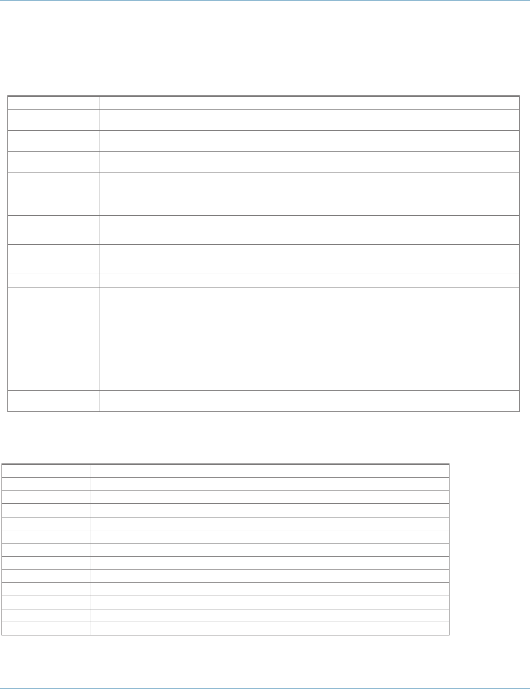
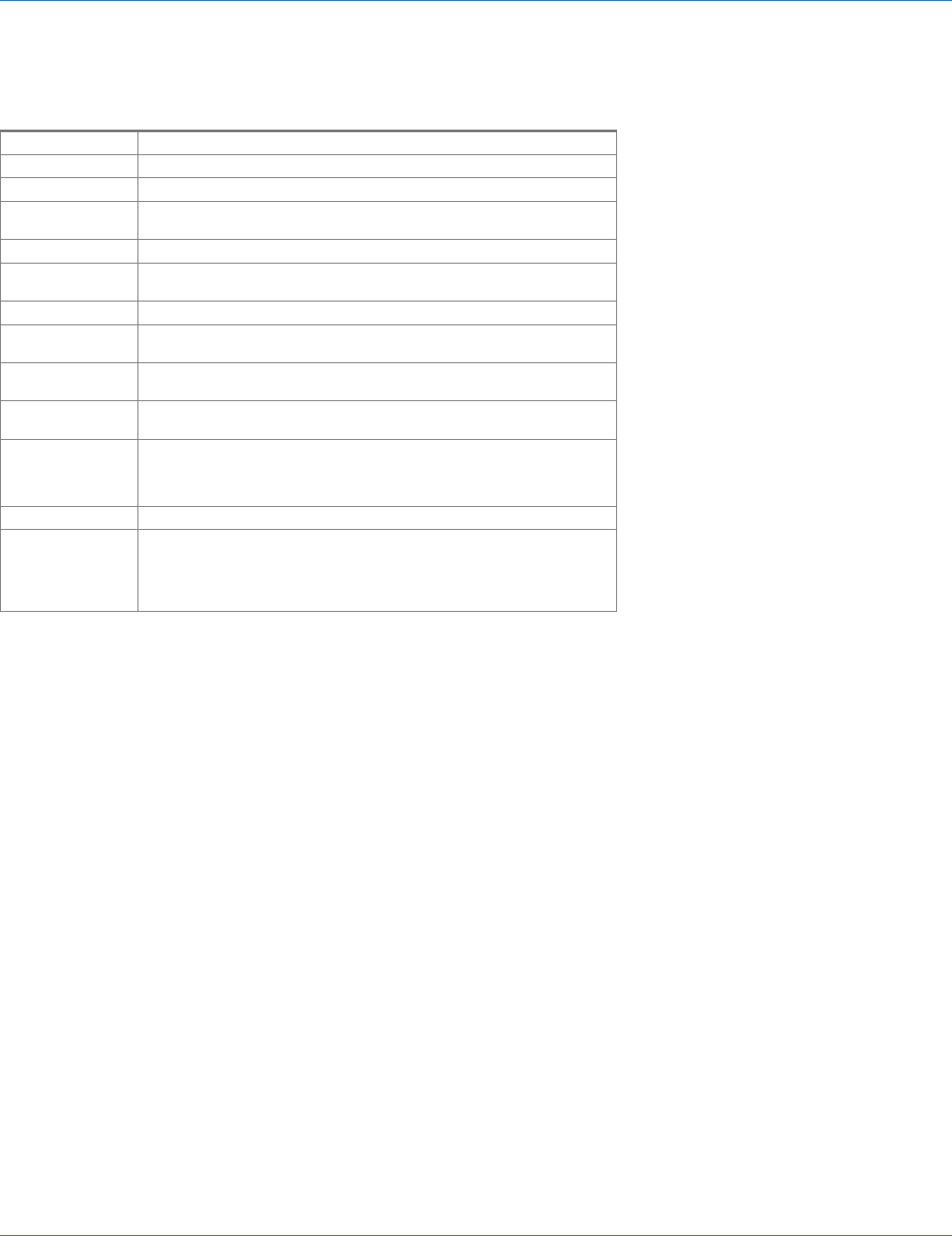
1.4 TCP/UDP Ports
Table 1-1. TCP/UDP ports.
Port Description Comments
80/tcp Always open for the Web server.
This port is used for configuration of the device using a web browser.
This port is always open no matter how you configure the device.
If you want to use this method to configure the device from outside of a firewall, then a firewall
must allow incoming connections to this port.
If you want to use this method to configure the device from the outside of a NAT, the NAT must be
configured to forward to this port.
771/tcp
This port is open when any serial
port is configured for VCOM
mode.
This port is used for communications with the VCOM device driver installed on the computer. This
port is open only if you configure any serial port for VCOM mode.
If you want to use VCOM from outside of a firewall, then you must allow incoming connections on
this port.
If you want to use VCOM from outside of a NAT, then you must forward to this port.
7000/tcp Always open for serial server
configuration over TCP.
This port is used for configuration and firmware upgrade of the device using the serial
server manager. This port is always open no matter how you configure the device.
If you want to configure the serial server from outside of a firewall using the serial server manager,
then the firewall must be configured to allow incoming connections on 7000/tcp and allow packets
addressed to 7000/udp to be received.
NOTE: Configuring over 7000/udp is not supported.
60000/tcp
This port is open when serial
port 1 is configured for paired-
mode server.
These ports are used to transfer handshake line state and break state in paired mode configuration.
These ports are open only if you configure the port for paired-mode server. Note that serial port 1
uses 60000/tcp, serial port 2 uses 60001/tcp, serial port 3 uses 60002/tcp, and serial port 4 uses
60003/tcp. If a port is not configured for paired-mode server, then the corresponding port is not
open.
If you want to connect to a paired-mode server from outside of a firewall, then you must allow
incoming connections on these ports.
If you want to connect to a paired-mode server from outside of a NAT, then you must forward to
these ports.
60001/tcp
This port is open when serial
port 2 is configured for paired-
mode server. Applies to LES422A
and LES424A only.
As above
60002/tcp
This port is open when serial
port 3 is configured for paired-
mode server. Applies to LES424A
only.
As above
60003/tcp
This port is open when serial
port 4 is configured for paired-
mode server. Applies to LES424A
only.
As above
68/udp This port is open when the
network mode is DHCP.
This port is used if you configure the device for DHCP mode (as opposed to Static IP). It is used to
communicate with the DHCP server.
This should only be used inside of a firewall or NAT.
7000/udp Always open for serial server
configuration over UDP.
These ports are used for configuration and firmware upgrade of the device using the serial server
manager. These ports are always open no matter how you configure the device.
If you want to configure the serial server from outside of a firewall using the serial server manager,
then the firewall must be configured to allow incoming connections on 7000/tcp and allow packets
addressed to 7000/udp to be received
8899/udp Always open for serial server
discovery.
This port is used for discovering serial servers. This port is always open no matter how you configure
the device.
NOTE: The device discovery only works on a local subnet. The port may not need to be configured
in a firewall or NAT.
Other User-specified ports.
Other TCP and UDP ports may be open, depending on what you specified for the device
configuration. THESE ARE THE PORTS SPECIFIED IN THE CONFIGURATION FILE.
If you want to use these other ports from outside of a firewall, then you must allow these ports.
If you want to use these other ports from outside of a NAT, then you must forward to these ports.
724-746-5500 | blackbox.com
Page 10
724-746-5500 | blackbox.com
Chapter 1: Specifications
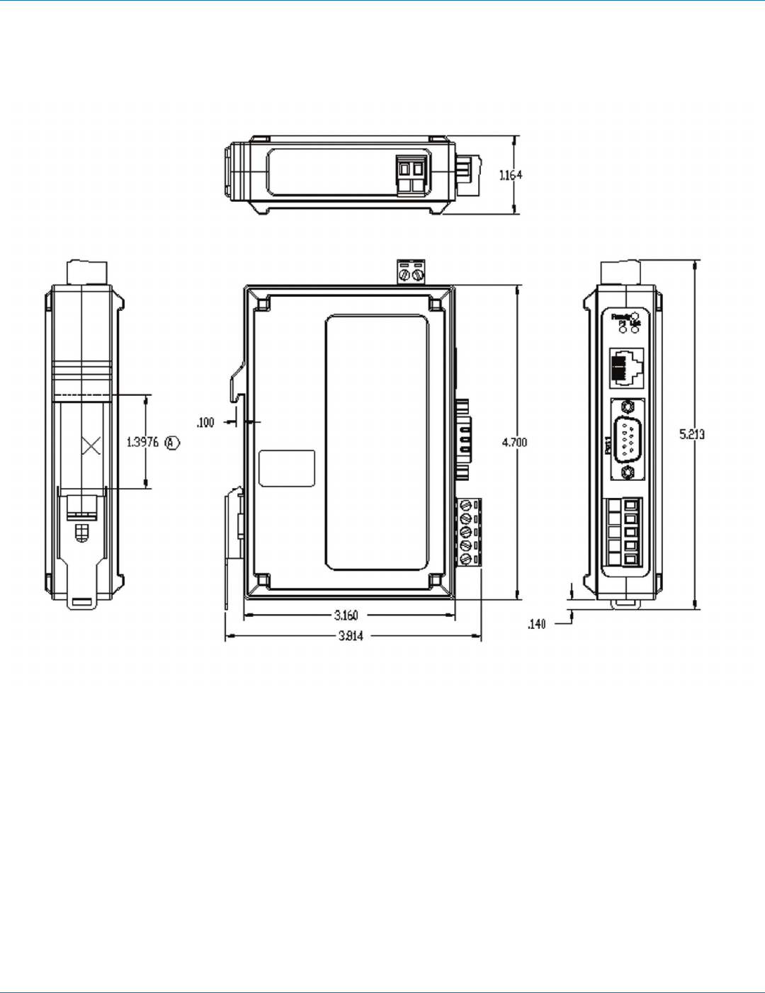
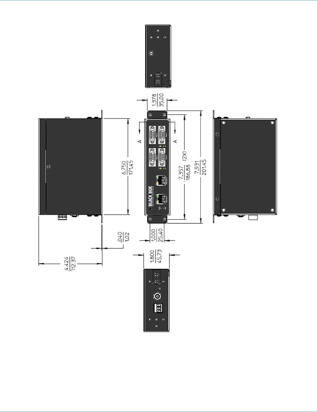
1.5 Dimensional Diagrams
Figure 1-1. Dimensional diagram of a LES421A or LES422A Hardened Serial Server (dimensions in inches).
724-746-5500 | blackbox.com
724-746-5500 | blackbox.com Page 11
Chapter 1: Specifications
Figure 1-2. Dimensional diagram of a LES424A Hardened Serial Server (dimensions in inches and millimeters).

724-746-5500 | blackbox.com
Page 12
724-746-5500 | blackbox.com
Chapter 2: Overview
2. Overview
2.1 Introduction
The 1-, 2-, and 4-Port Hardened Serial Servers connect serial devices (RS-232, RS-422, or RS-485) to Ethernet networks, allowing
the serial device to become a node on the network. The serial ports can be accessed over a LAN/WAN using Direct IP Mode,
Virtual COM Port, or Paired Mode connections. Hardened Serial Servers use 10BASE-T or 100BASE-TX copper network media.
All models also have an additional copper Ethernet pass-through port. Hardened Serial Servers are built for use in industrial
environments and feature heavy duty metal enclosures that are panel- and DIN-rail mountable. The product operates from a
range of DC power supply voltages and features pluggable terminal block power connectors. The LES424A also has a locking
barrel connector that facilitates redundant power sources.
Table 2-1. Available models.
Part Number Serial
Ports Serial Connectors Ethernet Media Ethernet
Connector 1 Ethernet
Connector 2 Power
LES421A 1
(1) DB9M and (1) 5-pin terminal block
NOTE: Use either the DB9 or the terminal
block connector, but not both at
the same time.
RJ-45 RJ-45 — (1) 2-wire terminal block
LES422A 2(2) DB9M RJ-45 RJ-45 — (1) 2-wire terminal block
LES424A 4(4) DB9M RJ-45 RJ-45 RJ-45 (1) 3-wire terminal block and (1) locking
barrel connector for redundant power
2.2 Features
• LES421A, LES422A: single Ethernet connector.
• LES424A: (2) Ethernet connectors (Ethernet passthrough ports).
• Multi-interface serial ports (RS-232, RS-422, RS-485).
• LES421A has DB9M and pluggable terminal block serial port connector options.
• LES422A and LES424A have DB9M serial port connectors.
• All serial ports are software selectable for RS-232, RS-422, or RS-485 2- and 4-wire communication.
• Configuration can be done via network or direct serial connection.
• Rugged metal case; DIN rail or panel mountable.
• Accepts DC power over a wide voltage range.
• LES424A has two power connections (pluggable terminal strip and locking barrel connector), which can be used for a
redundant power supply.
• Supports 10-/100-Mbps Ethernet with auto-selection.
• Configurable for TCP Client or Server, or UDP operation.
• Virtual COM port and Paired Mode capabilities.
• Upload firmware over the Ethernet port for future revisions/upgrades.
• Supports Windows XP (32/64 bit), 2003 Server (32/64 bit), Vista (32/64 bit), 2008 Server (32/64 bit), Windows 7 (32/64 bit).
• Configure Ethernet and serial port settings using Hardened Serial Server Software or built-in Web server.

724-746-5500 | blackbox.com
724-746-5500 | blackbox.com Page 13
Chapter 2: Overview
2.3 What‘s Included
Your package should include the following items. If anything is missing or damaged, contact Black Box Technical Support
at 724-746-5500 or info@blackbox.com.
LES421A or LES422A:
• 1- or 2-port Hardened Serial Server module.
• A printed quick start guide.
• This user manual in PDF format on CD-ROM
LES424A:
• 4-port Hardened Serial Server module.
• A printed quick start guide.
• This user manual in PDF format on CD-ROM
• (1) 3-position terminal block Phoenix connector
• (1) Panel mount kit: (2) brackets, (4) screws
• (1) DIN rail mounting kit: (1) DIN rail bracket, (3) screws
NOTE: To download this user manual, go to ftp://ftp.blackbox.com/anonymous/manuals/L/LES421A_2A_4A_USER_rev1.pdf or
visit the Black Box Web site (www.blackbox.com) and enter LES421A, LES422A, or LES424A in the search bar.
2.4 Hardware Description
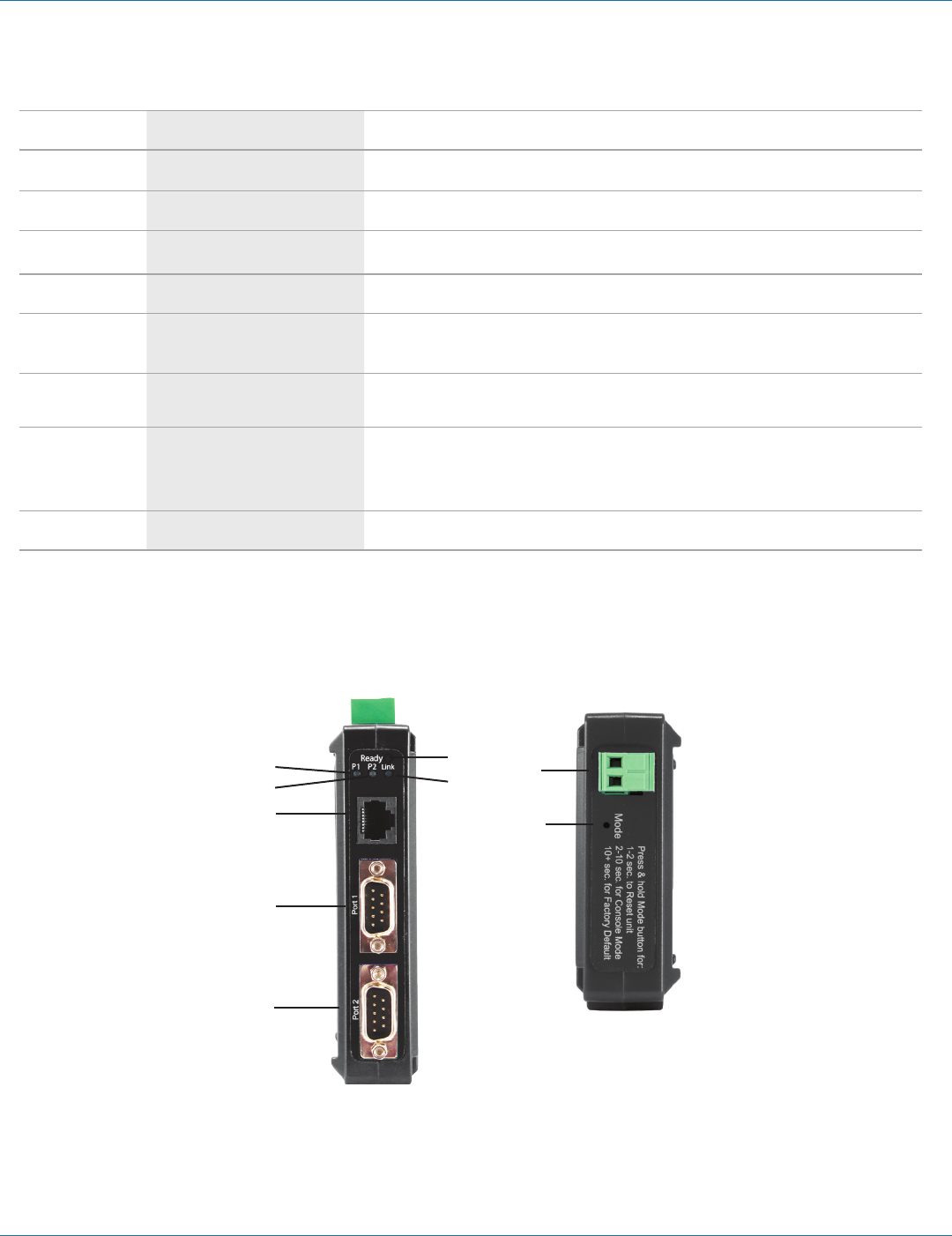
2.4.1 1-Port Hardened Serial Server (LES421A)
Figures 2-1 and 2-2 show the front and top panels of the LES421A. Table 2-2 describes its components.
5
1
2
3
7
6
8
4
Figures 2-1 and 2-2. LES421A front and top panels.
724-746-5500 | blackbox.com
Page 14
724-746-5500 | blackbox.com
Chapter 2: Overview
Table 2-2. LES421A components.
Number in Figure
2-1 or 2-2 Component Description
1(1) RJ-45 connector
Connects a standard Ethernet network drop using a straight-through RJ-45 male Ethernet cable.
2(1) 5-position terminal block connector
Connects to an RS-422 or RS-485 serial device when the DB9 M (RS-232) connector is disabled.
3(1) DB9 male connector
Connects to an RS-232 serial device when the 5-position terminal block (RS-422/RS-485) is disabled.
4(1) 2-wire terminal block connector
Removable 2-position terminal block with +, -, and chassis ground connections.
5(1) Serial Port LED
Flashes green when data is being transmitted or received on the serial port.
Lights steady green when the serial port is open.
6(1) Ethernet Link LED
Lights when a connection is made.
Flashes when there is data traffic on the Ethernet link.
7(1) Ready LED
Lights green continuously when the unit is initializing.
Flashes once per second when the system is operating correctly.
Off when something is wrong, for example, another device uses the same IP address.
8(1) Reset button
Used to initiate a hardware reset, enter console mode, or reload factory defaults.
2.4.2 2-Port Hardened Serial Server (LES422A)
Figures 2-3 and 2-4 show the front and top panels of the LES422A. Table 2-3 describes its components.
4
4
1
2
2
7
6
7
3
Figures 2-3 and 2-4. LES422A front and top panels.
724-746-5500 | blackbox.com
724-746-5500 | blackbox.com Page 15
Chapter 2: Overview
Table 2-3. LES422A components.
Number in Figure
2-3 or 2-4 Component Description
1(1) RJ-45 connector
Connects a standard Ethernet network drop using a straight-through RJ-45 male Ethernet cable.
2(2) DB9 male connectors
Connects to RS-232, RS-422, or RS-485 serial devices.
3(1) 2-wire terminal block connector
Removable 2-position terminal block with +, -, and chassis ground connections.
4(2) Serial Port LEDs
Flashes green when data is being transmitted or received on the serial port.
Lights steady green when the serial port is open.
5(1) Ethernet Link LED
Lights when a connection is made.
Flashes when there is data traffic on the Ethernet link.
6(1) Ready LED
Lights green continuously when the unit is initializing.
Flashes once per second when the system is operating correctly.
Off when something is wrong, for example, another device uses the same IP address.
7(1) Reset button
Used to initiate a hardware reset, enter console mode, or reload factory defaults.
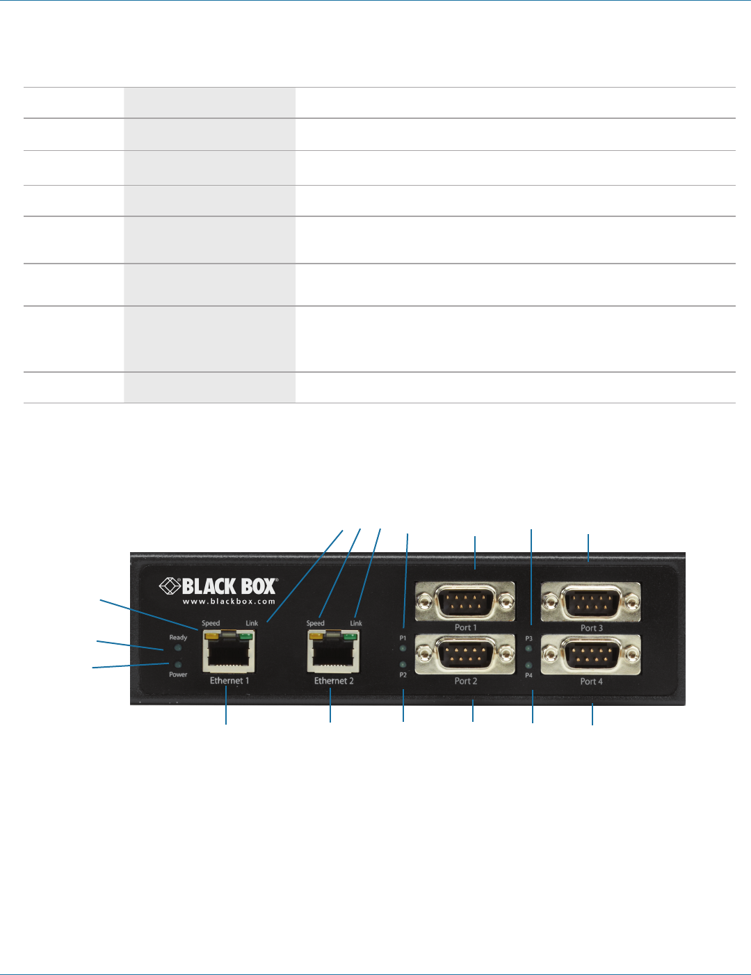
2.4.3 4-Port Hardened Serial Server (LES424A)
Figures 2-5 and 2-6 show the front and side panels of the LES424A. Table 2-4 describes its components.
7 7 5 6 5 6
3
2
1
4 3 4 5 6 5 6
Figure 2-5. LES424A front panel.
724-746-5500 | blackbox.com
Page 16
724-746-5500 | blackbox.com
Chapter 2: Overview
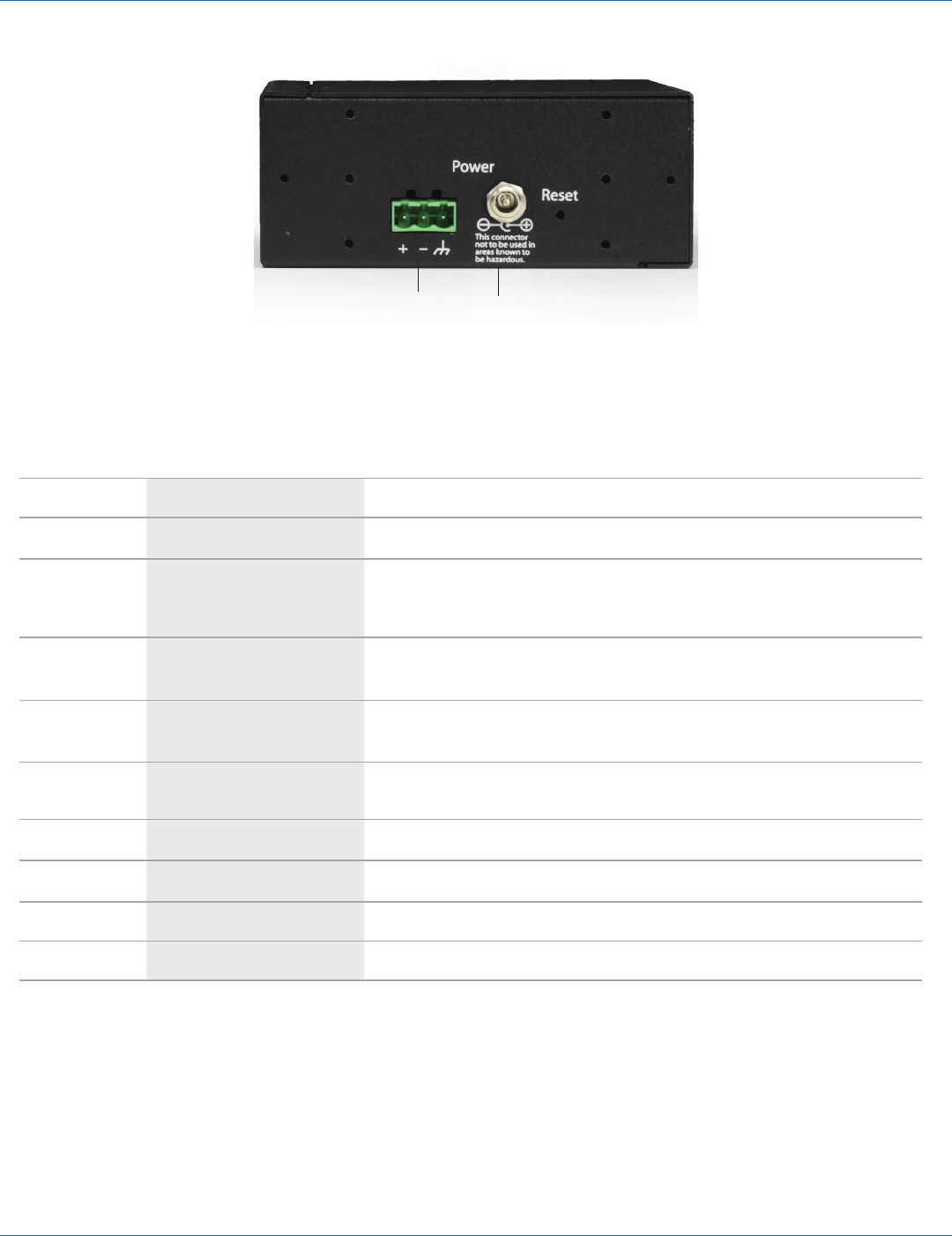
Figure 2-6. LES424A back panel.
Table 2-4. LES424A components.
Number in Figure
2-5 or 2-6 Component Description
1(1) Power LED
Lights when power to the unit is on.
2(1) Ready LED
Lights green continuously when the unit is initializing.
Flashes once per second when the system is operating correctly.
Off when something is wrong, for example, another device uses the same IP address.
3(2) Ethernet Speed LEDs
Lights green when the Ethernet connection is operating at 100 Mbps.
Off when the connection is operating at 10 Mbps.
4(2) Ethernet Link LEDs
Lights when a connection is made.
Flashes when there is data traffic on the Ethernet link.
5(4) Serial Port LEDs
Flashes green when data is being transmitted or received on the serial port.
Lights steady green when the serial port is open.
6(4) DB9 male connectors
Connects to RS-232, RS-422, or RS-485 serial devices.
7(2) RJ-45 connectors
Enable the server to act as an Ethernet switch.
8(1) 3-wire terminal block connector
Removable 3-position terminal block with +, -, and chassis ground connections.
9(1) Reset button
Used to initiate a hardware reset, enter console mode, or reload factory defaults.
2.5 Configuration Software
Manager configuration software enables you to find connected Hardened Serial Servers, configure them, upgrade Hardened Serial
Server firmware, and save/load configuration files. It features a graphical user interface (GUI) that is convenient and easy to use.
The software also makes it easy to add and remove virtual COM ports on your computer.
9
8
724-746-5500 | blackbox.com
724-746-5500 | blackbox.com Page 17
Chapter 3: Installation and Setup
3. Installation and Initial Setup
This section describes how to install the Hardened Serial Server and configure the device.
NOTE: In this section, devices to be connected to the Hardened Serial Server’s serial connections are simply referred to as the
“serial device.”
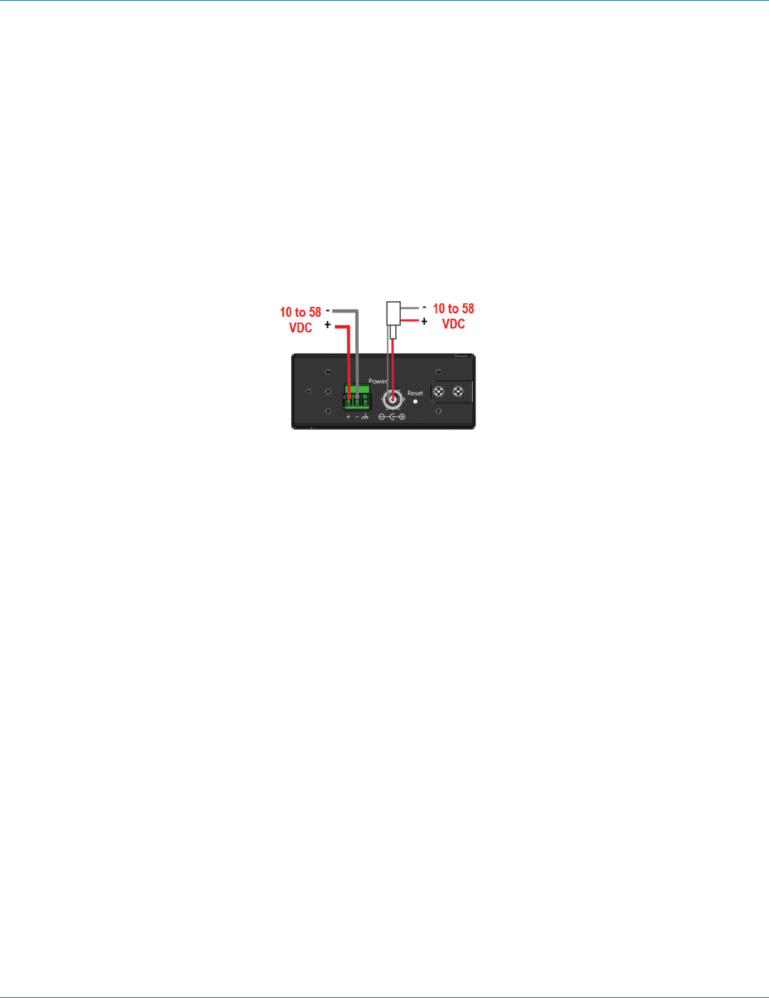
3.1 Connecting the Power Supply
Connect a DC power supply to the power terminals on the side of the Hardened Serial Server. Polarity of the wires is indicated
underneath each connector. Acceptable voltages are between 10 VDC and 58 VDC. The power supply must be capable of
supplying 4 watts for the LES421A or LES422A or 6 watts for the LES424A.
Figure 3-1. LES421A, LES422A, and LES424A power supply connections.
3.2 Connecting Hardened Serial Servers to Serial Devices
The Hardened Serial Servers can be connected to serial devices using RS-232, RS-422, RS-485 2-wire, or RS-485 4-wire
communication. LES422A and LES424A models use (2) or (4) DB9 M connectors. LES421A models use either (1) DB9 M connector
or (1) 5-position terminal strip.
3.2.1 RS-232
The 2- and 4-port models, along with the 1-port model when using its DB9M connector, support seven RS-232 signal lines (TD,
RD, DTR, DSR, RTS, CTS, DCD) plus Signal Ground.
The 1-port model, when using its 5-position pluggable terminal block, supports four signal lines (TD, RD, RTS, CTS) plus Signal
Ground.
NOTE: Only one connector (DB9M or 5-position terminal block) can be used on the LES421A.
Signals are single-ended and referenced to Signal Ground. Default communications parameters are 9600, 8, N, 1 (9600 baud,
8 data bits, no parity, 1 stop bit), and no flow control.
NOTE: The LES421A, LES422A, and LES424A are configured as DTEs. If they are connected to a computer or other DTE device,
use a null-modem (crossover) cable. If the serial device is configured as a DCE, use a straight-through cable.
724-746-5500 | blackbox.com
Page 18
724-746-5500 | blackbox.com
Chapter 3: Installation and Setup
3.2.2 RS-422
RS-422 connections support two signal pairs: TDA (-), TDB (+), RDA (-), RDB (+), and GND. The data lines are differential pairs
(A and B) in which the B line is positive relative to the A line in the idle (mark) state. In RS-422, the transmitter is always enabled.
Signal Ground provides a common mode reference for the signal lines.
3.2.3 RS-485
RS-485 connections support 2-wire or 4-wire operation. In RS-485 mode, the transmitter is only enabled when the Hardened
Serial Server is transmitting data on the line. This allows other devices to share the bus.
When configured for 4-wire operation, the connection supports two signal pairs: TDA (-), TDB (+), RDA (-), RDB (+), and GND.
This makes full-duplex operation possible. The data lines are differential pairs (A and B) in which the B line is positive relative to
the A line in the idle (mark) state. Signal Ground provides a common mode reference for the signal lines.
When configured for 2-wire operation, the connection supports one signal pair: Data A (-) and Data B (+). These lines transmit
and receive signals using half-duplex operation. The data lines are differential with the Data B line positive relative to Data A in the
idle (mark) state. Signal Ground provides a common mode reference for the signal lines.
NOTE: Refer to Appendix B for connector pinout information.
Serial device
Serial connection
Network
Figure 3-2. LES424A connections.
3.3 Connecting RS-232/422/485 Hardened Serial Servers to a Network
Ethernet Connection (10BASE-T/100BASE-TX)
When connecting a Hardened Serial Server equipped with a 10BASE-T/100BASE-TX network connection (RJ-45 connector) to an
Ethernet network, use a standard unshielded twisted-pair cable. When installing this equipment in industrial or other electrically
noisy environments, we strongly recommend that you use STP (shielded twisted pair) cable. The Hardened Serial Server has an
automatic MDI-X interface that will sense the pinout of the network interface and provide a crossover connection if required.
3.4 Ethernet Passthrough Port
4-Port Hardened Serial Servers (LES424A) are equipped with an additional RJ-45 network port, also known as a
passthrough port. This port can be used to connect additional Ethernet devices, such as a local workstation or second serial
server, to the network.
Network
Local Ethernet
device
Figure 3-3. Ethernet passthrough port (on LES424A only).
724-746-5500 | blackbox.com
724-746-5500 | blackbox.com Page 19
Chapter 3: Installation and Initial Setup
3.5 Hardened Serial Server Configuration
The Hardened Serial Servers can be configured using three methods:
• Via the network using Hardened Serial Server Software.
• Via the network using a Web browser.
• Via a serial port using Hardened Serial Server Software (Console Mode).
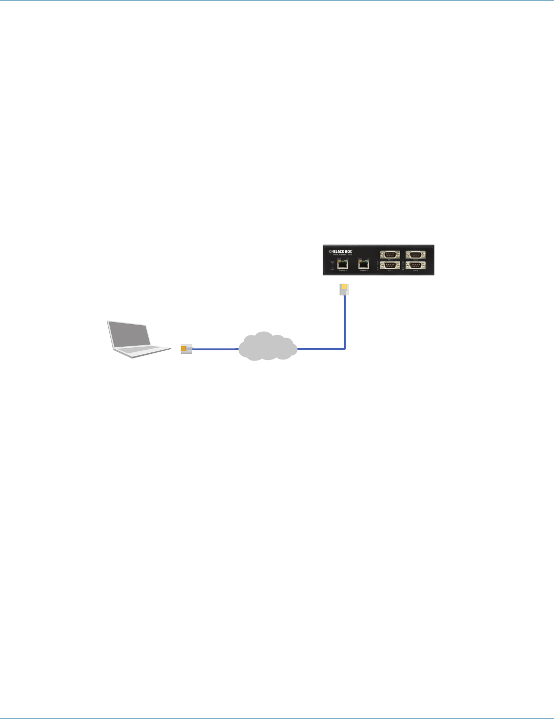
3.5.1 Configuring via the Network using Hardened Serial Server Software
Hardened Serial Servers can be configured over the network using Hardened Serial Server Software running on a networked PC.
Hardened Serial Server Software includes a discovery function that makes it possible to detect the Hardened Serial Server on the
network if you do not know its IP address. Once the Hardened Serial Server has been detected, you can use the Hardened Serial
Server Software to change its settings.
NOTE: For more information on how to use Hardened Serial Server Software to configure your Hardened Serial Server, refer to
Chapter 4: Configuring the Hardened Serial Server.
Network
Figure 3-4. Network setup.
3.5.2 Configuring via the Network using a Browser
Hardened Serial Servers can also be configured over the network using a standard internet browser, such as Internet Explorer® or
Firefox® running on a networked PC. To do so, you must know the IP address of the Hardened Serial Server. Your Hardened Serial
Server comes from the factory pre-configured to receive an IP address from a DHCP Server. If a DHCP server is not available, it will
default to 169.254.102.39.
NOTE: For more information on how to use Hardened Serial Server Software to configure your Hardened Serial Server, refer to
Chapter 4: Configuring the Hardened Serial Server.
724-746-5500 | blackbox.com
Page 20
724-746-5500 | blackbox.com
Chapter 3: Installation and Initial Setup
3.5.3 Configuring via a Serial Port using Hardened Serial Server Software (Console Mode)
Your Hardened Serial Server can be configured via any serial port, using Hardened Serial Server Software. To use this feature, a
serial port on the serial server must be connected to the serial port of a PC (using a null modem cable).
Figure 3-5. Console mode setup.
To configure the serial server, it must be put into Console Mode, using the Reset switch.
NOTE: Refer to Section 6.2 for information on how to use the Reset switch to enter Console Mode.
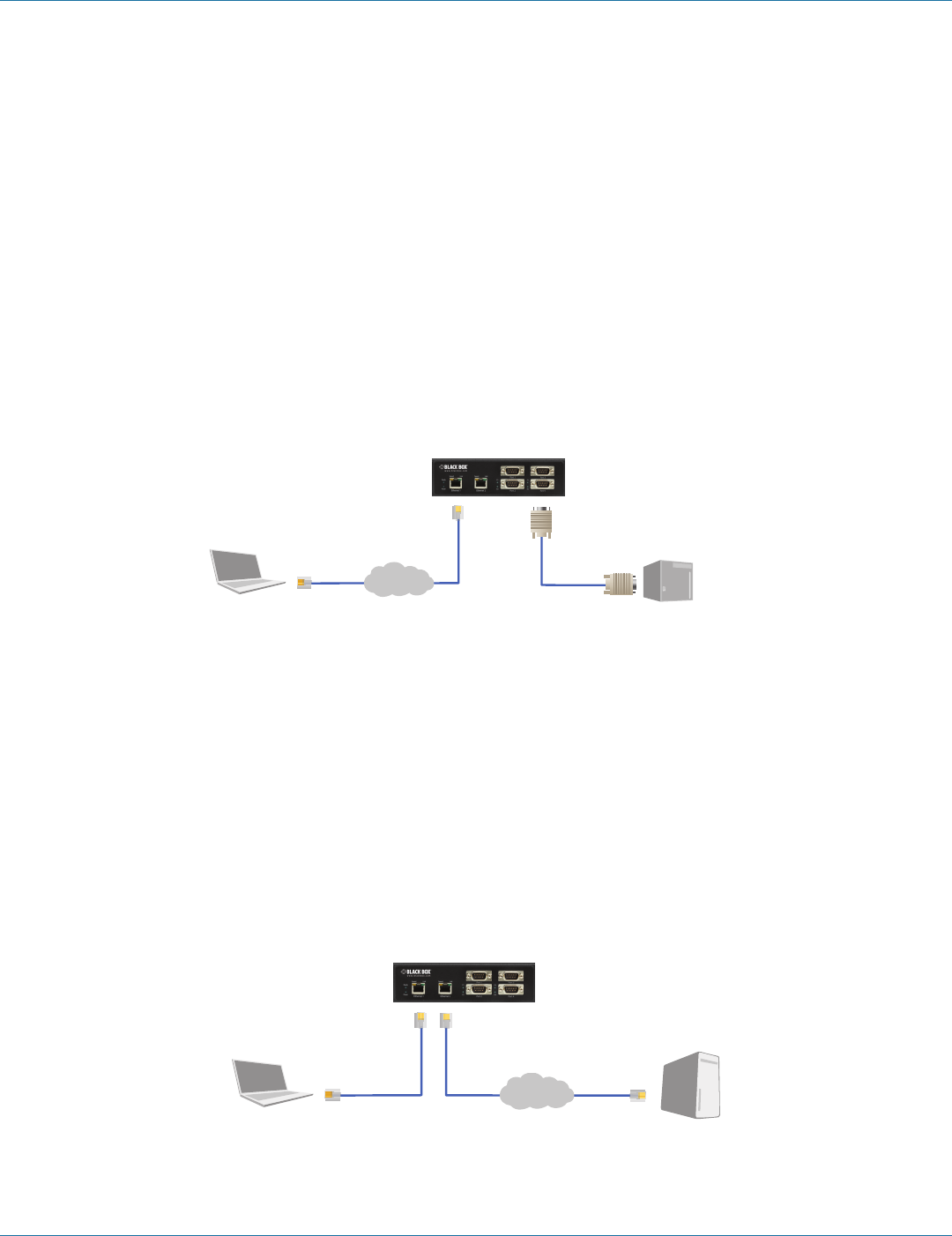
3.6 Hardened Serial Server Operational Connections
Hardened Serial Servers can operate in Direct IP, Virtual COM Port, and Paired Modes.
In Direct IP Mode, applications can use TCP/IP socket connections or UDP/IP datagrams to communicate with the COM ports on
the serial server. In this type of application, the serial server is configured as a TCP or UDP server. The socket program running on
the PC establishes a communication connection with the serial server. The data is sent directly to and from the serial port on the
server.
Network
Serial devices
Serial devices
Figure 3-6. Direct IP and Virtual COM port connection.
724-746-5500 | blackbox.com
724-746-5500 | blackbox.com Page 21
Chapter 3: Installation and Initial Setup
In Virtual COM Port Mode, the serial ports on the serial server appear to applications running on the host PC as if the serial ports
were physically located on the host PC. When a virtual COM port is configured on the PC (using Serial Server Software), a new
COM port appears in the Device Manager. Windows programs are able to interface to the virtual COM port using standard
Windows API calls. When a program on the PC opens the new COM port, it communicates directly with the remote serial device
connected to the serial server.
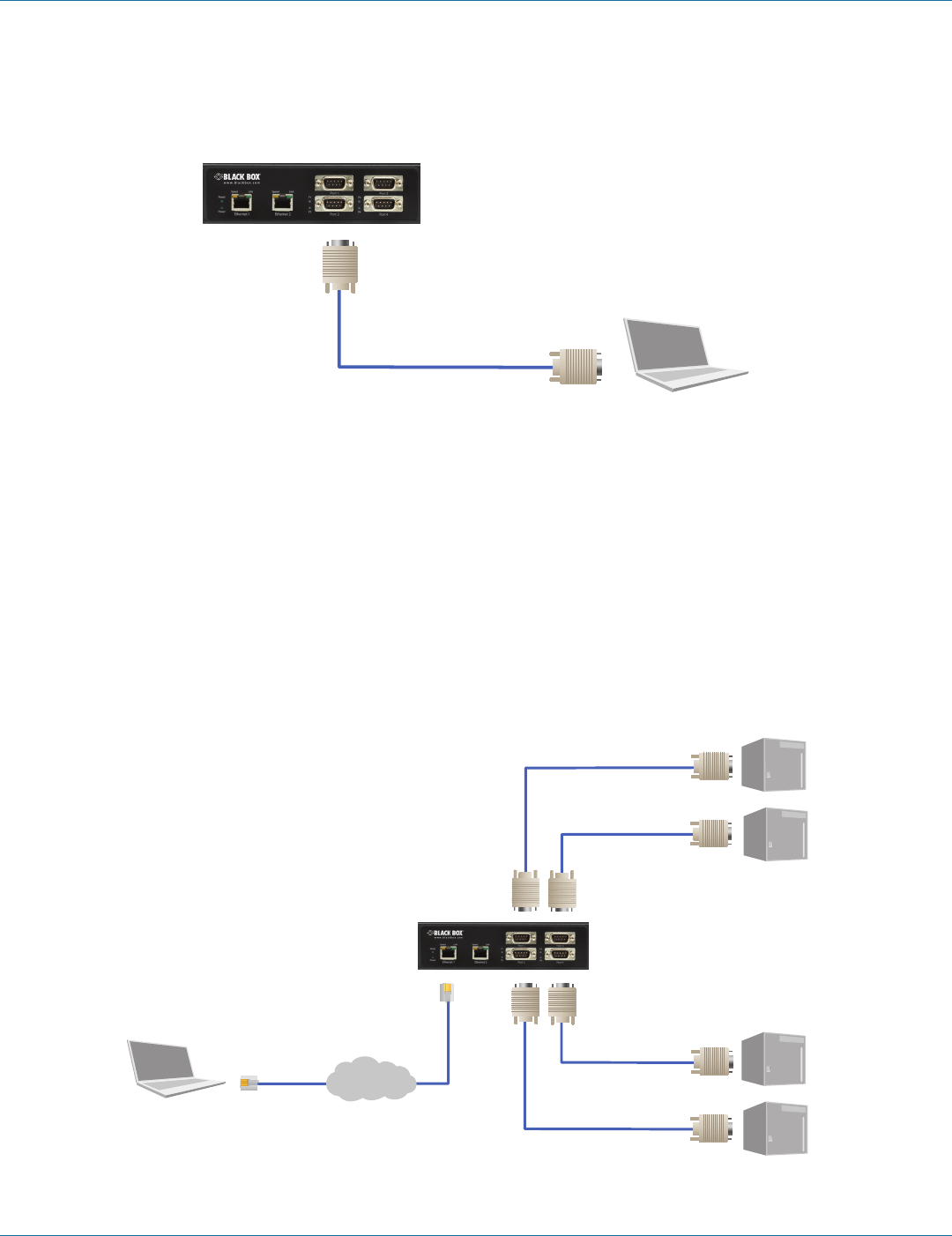
In Paired Mode, two Hardened Serial Servers are used to provide a virtual cable connection between two remote serial devices
using the Ethernet network. The end serial devices communicate data and handshake information directly, as if they were
physically connected in a point-to-point serial connection. Paired Mode devices are set up as shown in the following diagram and
configured using Hardened Serial Server Software or a web interface.
Network
Serial device Serial device
Figure 3-7. Paired mode setup.
3.7 Installing and Starting Hardened Serial Server Software
Hardened Serial Server Software is a Windows-based application used to configure Hardened Serial Servers. Install it on your PC
from the included CD. Installation should launch automatically when the CD is placed in the CD-ROM drive.
Follow the prompts to install the software.
Once the program is installed, go to the “Start > Programs” menu and run the program.
The Hardened Serial Server Software Discovery window appears.
Figure 3-8. Discovery window.

724-746-5500 | blackbox.com
Page 22
724-746-5500 | blackbox.com
Chapter 3: Installation and Initial Setup
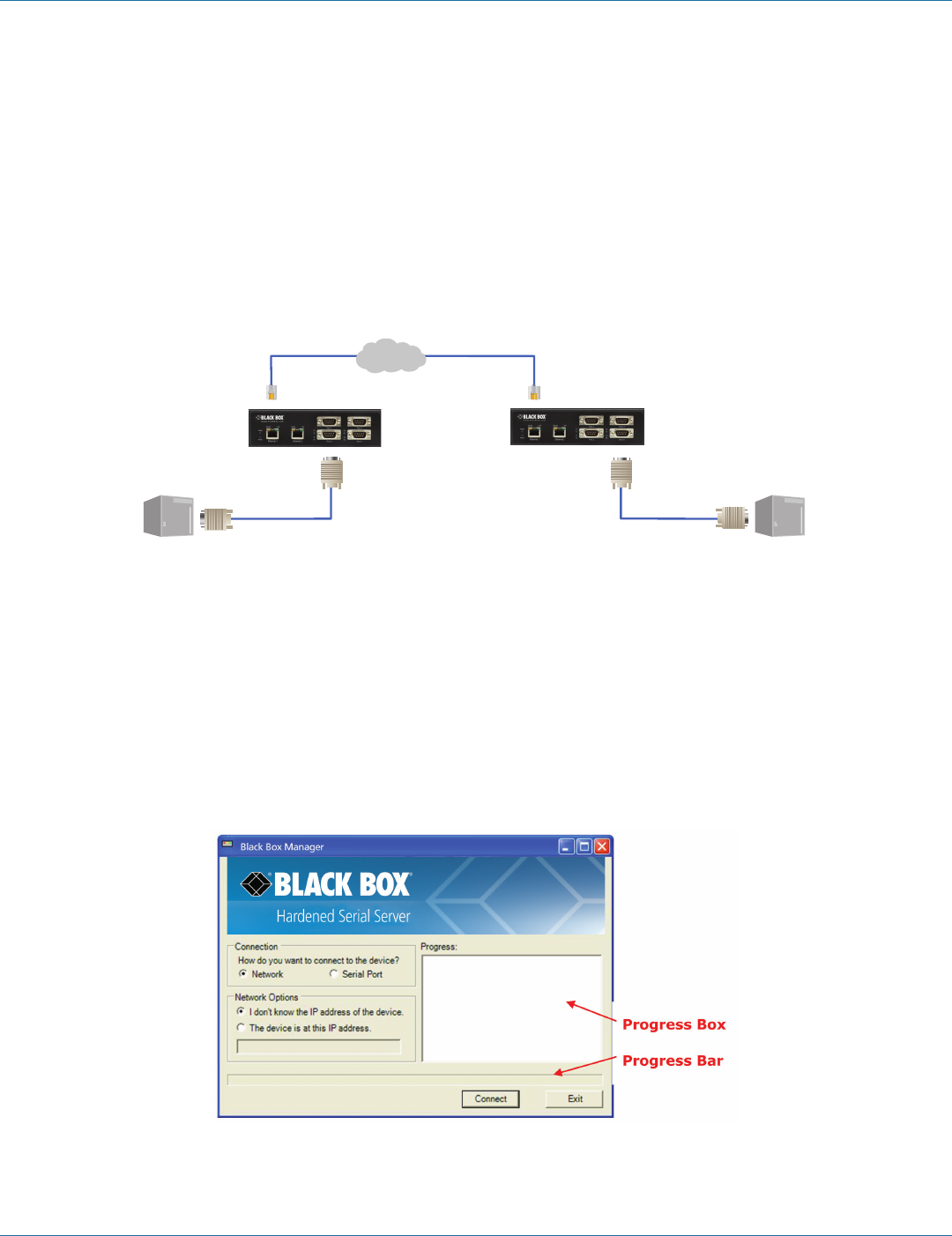
3.8 Discovering Hardened Serial Servers
If you are configuring the Hardened Serial Server via the network, select “Network”; if you are configuring it via the serial port,
select “Serial Port.”
If you already know the IP address of the Hardened Serial Server, click “The device is at this IP address”; if not, leave “I don’t
know the IP address of the device” selected.
Click “Connect.” The Progress text box and bar graph provide information to indicate whether serial servers are detected and
how far along the process is.
The text in the Progress box appears in various colors, depending on the message type.
Table 3-1. Progess box text colors.
Color Description
Black A step in the discovery process.
Dark Blue A device was not found.
Dark Green A device was found.
Dark Red An error occurred.
If one or more devices are found, the discovery window closes automatically and the Configuration window appears.
724-746-5500 | blackbox.com
724-746-5500 | blackbox.com Page 23
Chapter 4: Configuring the Hardened Serial Server
4. Configuring the Hardened Serial Server
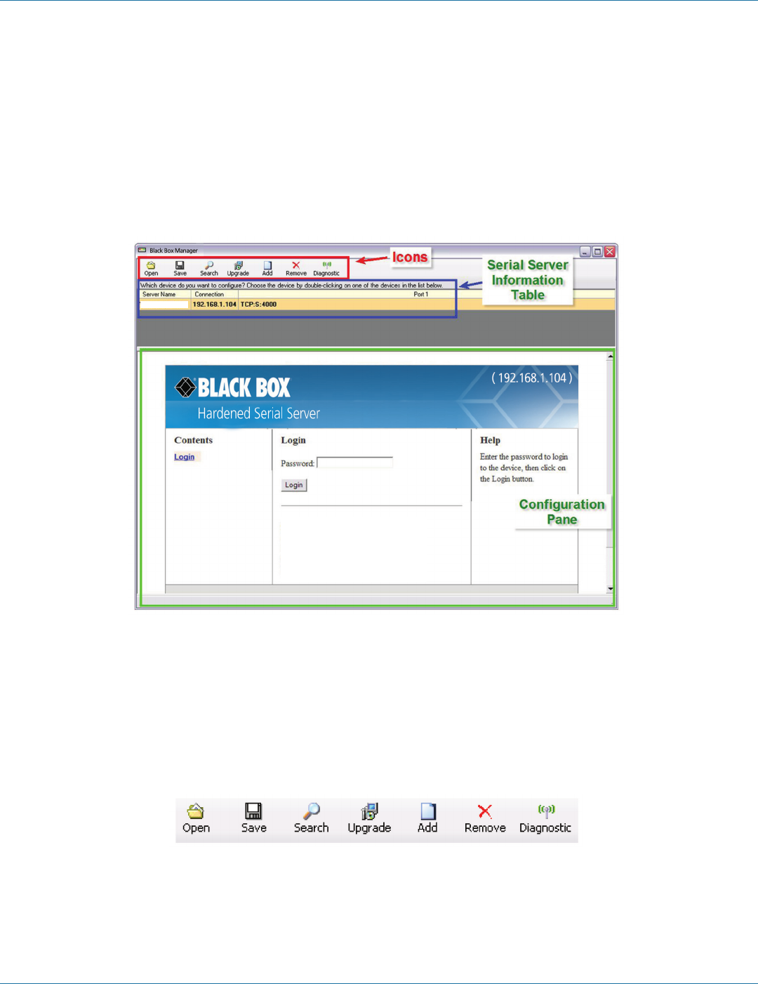
4.1 Overview of the Hardened Serial Server Software
The Hardened Serial Server Software configuration window includes three areas:
• Icons
• Hardened Serial Server information table
• Configuration pane
Figure 4-1. Hardened Serial Server Software Configuration window.
NOTE: The screen shots shown in this manual refer to the LES421A. Your screen will display the model name/number and serial
number of your device (LES421A, LES422A, or LES424A). All menus, functions and options shown on the screen shots in
this manual apply to your LES421A, LES422A, or LES424A device.
4.1.1 Icons
Figure 4-2. Configuration Window Icons.
• Open—Open a Hardened Serial Server configuration file.
• Save—Save the current Hardened Serial Server configuration to a file.
• Search—Initiate a search for Hardened Serial Servers.
Model: LES421A
Firmware Version: 1.6.0
Hardware Version: 0
MAC Address: 00:8C:10:13:29:E6
Link Status: 100BASE-T full duplex
LES421A
724-746-5500 | blackbox.com
Page 24
724-746-5500 | blackbox.com
Chapter 4: Configuring the Hardened Serial Server
• Upgrade—Upgrade the firmware in a Hardened Serial Server (see Chapter 5).
• Add—Add a Virtual COM Port to the host PC (see Section 4.10).
• Remove—Remove a Virtual COM Port from the host PC (see Section 4.11).
• Diagnostic—Perform Hardened Serial Server diagnostics (see Chapter 7).
4.1.2 Hardened Serial Server Information Table
The Hardened Serial Server information table contains information about all Hardened Serial Servers that have been discovered on
the network or serial ports.
Table 4-1. Serial server information table.
Server Name Connection Port 1 Port 2 Port 3 Port 4
LES421A 169.254.0.41 TCP:S:4000=COM5, in use — — —
LES422A 169.254.0.42 TCP: 5000 = COM6 TCP: 5001 = COM7 — —
LES424A 169.254.0.43 TCP: 6000 = COM8 TCP: 6001 = COM9 TCP: 6002 = COM10 TCP: 6003 = COM11
The table displays the following information for each Hardened Serial Server:
• Server Name—the name reported by the Hardened Serial Server.
• Connection—the IP address of the Hardened Serial Server.
• Port 1, Port 2, Port 3, and Port 4.
- Communications protocol assigned to the serial port (TCP, UDP, or Paired mode).
- Whether the port initiates connections (Client mode) or accepts connections (Server mode).
- TCP port number or UDP port number.
- The virtual COM port assignment on the local PC (if assigned).
- Whether the Hardened Serial Server's serial port is being used by anyone on the network.
The status of whether the Hardened Serial Server in use is updated periodically.
When a Hardened Serial Server's IP address is configured for a network that is not within the local network's range, the Hardened
Serial Server's information is displayed in a different color (yellow).
4.1.3 Configuration Pane
The configuration pane is essentially a Web browser.
LES421A
Figure 4-3. Configuration Pane.
724-746-5500 | blackbox.com
724-746-5500 | blackbox.com Page 25
Chapter 4: Configuring the Hardened Serial Server
It includes the following:
• Masthead with the name and IP address of the currently selected Hardened Serial Server.
• Contents sidebar (on the left side) containing hyperlinks to the following configuration pages:
- General
- Network
- Port x Serial (x = port number; each serial port connection is represented by a hyperlink)
- Port x Network (x = port number; each serial port connection is represented by a hyperlink)
- Save
- Login/Logout
• Configuration settings area in the middle of the pane where you can select the settings desired for operation of the Hardened
Serial Server.
• Help sidebar (on the right side) containing helpful descriptions, explanation, and suggestions for configuring the serial server.
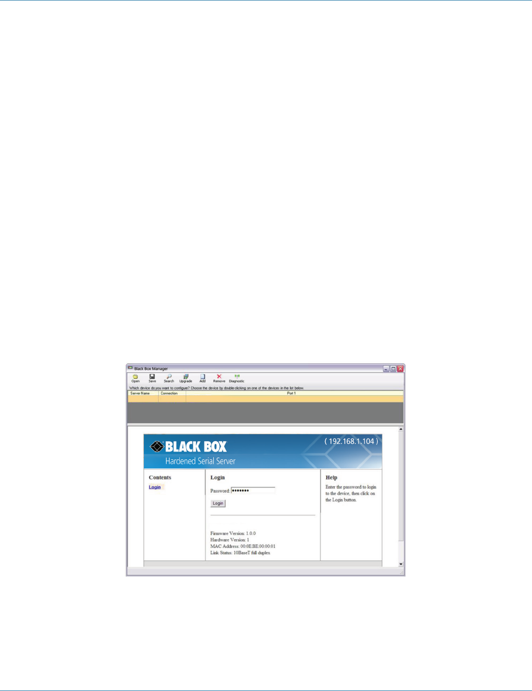
4.2 Logging In
You can log in to any Hardened Serial Server listed in the Server Information Table.
To log in:
1. Select the row associated with the desired Hardened Serial Server. The Login page appears.
2. Type the password into the Password box. The default password is blank.
Figure 4-4. Login page.
3. Click “Login.”
The “General Configuration” page appears.
724-746-5500 | blackbox.com
Page 26
724-746-5500 | blackbox.com
Chapter 4: Configuring the Hardened Serial Server
4.3 Navigating the Configuration Pages
There are two ways to move from page to page in the Hardened Serial Server Software: by clicking a specific link, or by clicking
“Next” or “Back” to move through the pages sequentially.
NOTE: Always remember to click “Save” before leaving a page to ensure your settings are saved.
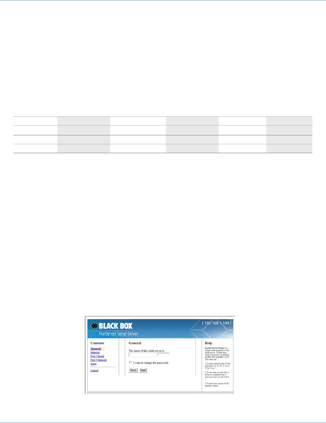
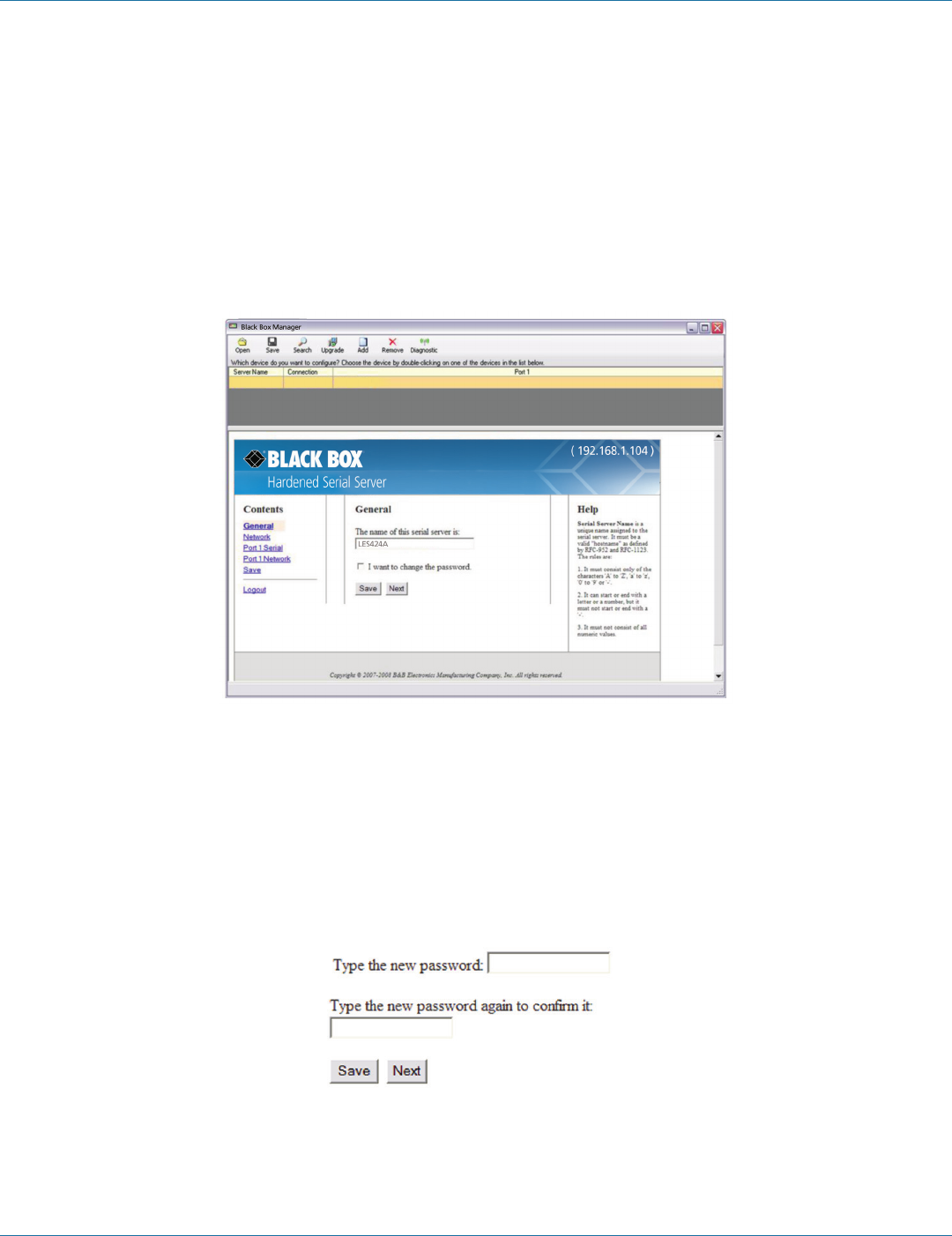
4.4 Setting Up the Hardened Serial Server Name and Password
On the General Configuration page you can do the following:
• Change the name of the Hardened Serial Server.
• Initiate a login password change.
Figure 4-5. General Configuration page.
4.4.1 Changing the Hardened Serial Server's Name
1. Type the new name into the “Hardened Serial Server Name” text box.
2. Click “Save.”
4.4.2 Changing the Password
1. Select the “I want to change the password” check box.
Two text boxes appear.
Figure 4-6. Changing the password.
2. Type the new password into both boxes.
3. Click “Save.”
724-746-5500 | blackbox.com
724-746-5500 | blackbox.com Page 27
Chapter 4: Configuring the Hardened Serial Server
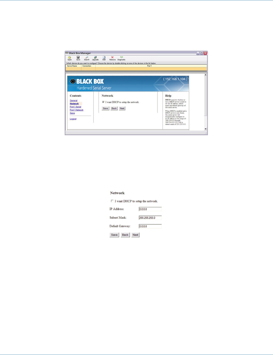
4.5 Setting Up IP Addressing
On the Network Configuration page, you can configure the Hardened Serial Server to use dynamic (DHCP) or static IP addressing
on the network.
Figure 4-7. Network Configuration page.
4.5.1 Setting Up Dynamic IP Addressing
1. Select the “I want to use DHCP to setup the network” check box.
4.5.2 Setting Up Static IP Addressing
1. Ensure the “I want to use DHCP to setup the network” box is unchecked.
Figure 4-8. IP Address settings.
2. Type the IP Address, Subnet Mask, and Default Gateway addresses in the appropriate boxes.
724-746-5500 | blackbox.com
Page 28
724-746-5500 | blackbox.com
Chapter 4: Configuring the Hardened Serial Server
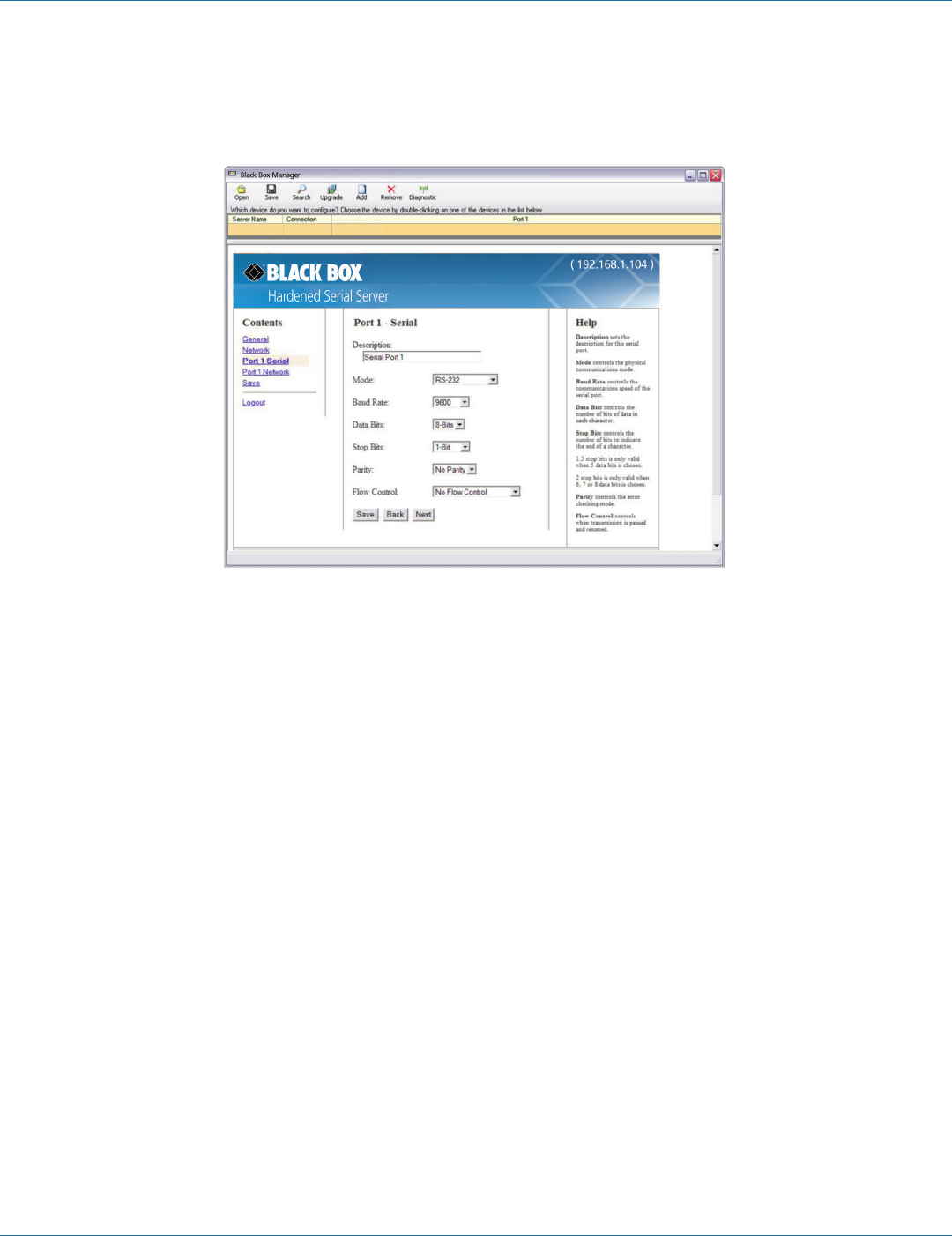
4.6 Setting Up Serial Ports
On the Serial Port Configuration page, you can configure the communications parameters of the current serial port. Parameters
include the port mode, baud rate, data bits, parity, stop bits, and type of flow control.
Figure 4-9. Serial Port Configuration page.
1. Mode—select the type of serial connection (RS-232, RS-422, RS-485 2-wire, or RS-485 4-wire) required by the serial device.
2. Baud Rate—select the Baud Rate (between 75 baud and 230,400 baud) required to communicate with the serial device.
3. Data Bits—select the number of Data Bits (5, 6, 7, or 8) required to communicate with the serial device.
4. Stop Bits—select the number of Stop Bits (1, 1.5, or 2) required to communicate with the serial device.
5. Parity—select the Parity setting (None, Even, Odd, Mark, or Space) required to communicate with the serial device.
6. Flow Control—select the Flow Control setting (None, RTS/CTS, or X-ON/X-OFF) required to communicate with the serial
device.
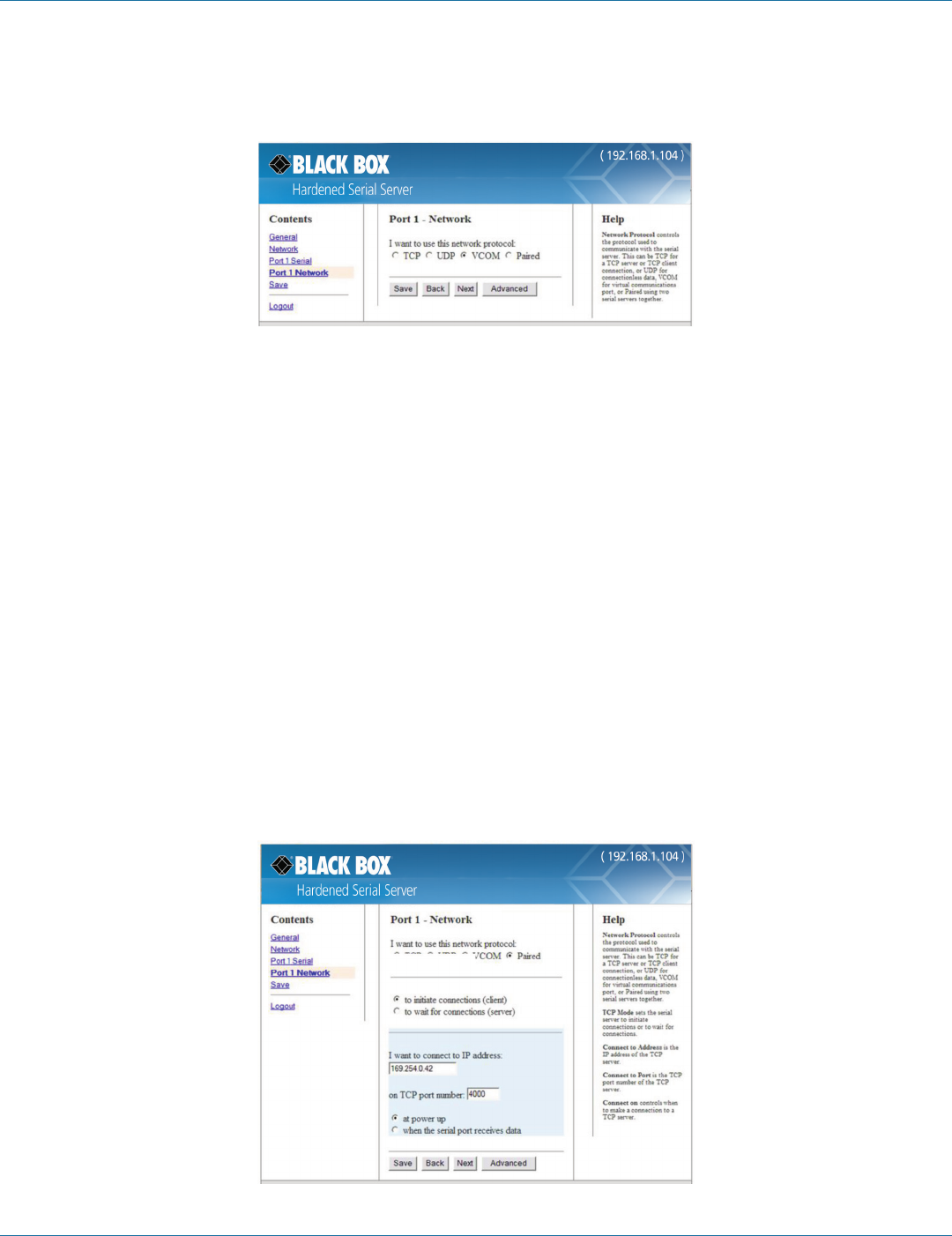
4.7 Setting Up Port Network Parameters
On the Port Network Parameters Configuration page, you can configure the port to use UDP, TCP, VCOM, or Paired protocols in
several different modes.
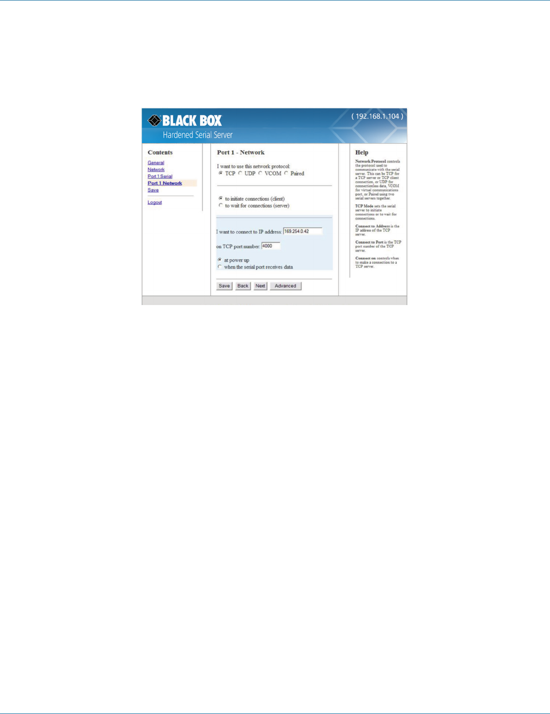
4.7.1 TCP Configuration
Transmission Control Protocol (TCP) provides reliable connection-oriented network communication with error checking. In TCP
mode, the Hardened Serial Server can be configured as a client or a server.
When you configure the Hardened Serial Server as a TCP client, it initiates a connection with a remote server on the network.
You must set up the IP address and port number of the remote server that you want the client (Hardened Serial Server) to
communicate with. You also select whether you want the Hardened Serial Server to connect at power up or only when it receives
data from the device connected to its serial port.
724-746-5500 | blackbox.com
724-746-5500 | blackbox.com Page 29
Chapter 4: Configuring the Hardened Serial Server
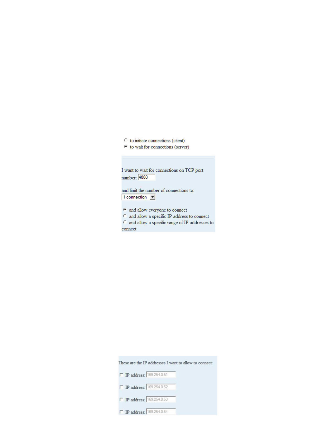
When the Hardened Serial Server is configured as a TCP server, it waits for an incoming connection request from another network
device. You must set up the TCP port number that the Hardened Serial Server will listen for incoming connections and set the
maximum number of simultaneous connections it will support (one for the LES421A, up to two for the LES422A, and up to four
for the LES424A). You can also set up the Hardened Serial Server to accept incoming connection requests only from certain IP
addresses or ranges of IP addresses.
Figure 4-10. TCP configuration.
Setting the Hardened Serial Server to operate as a TCP Client
1. Select “TCP” protocol.
2. Select “to initiate connections (client).”
3. Type the IP address into the “I want to connect to IP address:” box.
4. Type the TCP port number of the server into the “on TCP port number:” box.
5. Select:
• “at power up”—if you want the Hardened Serial Server to always be connected.
• “when the serial port receives data”—if you only want to establish a connection when there is data to be sent.
Setting the Hardened Serial Server to operate as a TCP Server
1. Select TCP protocol.
2. Select “to wait for connections (server).”
The configuration options change. The server IP address box disappears and the “number of connections” box appears.
3. Type the port number in the “I want to wait for connection on TCP port number:” box.
4. Select the maximum number of connections desired in the “and limit the number of connections to:” drop down box.

724-746-5500 | blackbox.com
Page 30
724-746-5500 | blackbox.com
Chapter 4: Configuring the Hardened Serial Server
Figure 4-11. TCP server settings.
4.7.2 UDP Configuration
UDP (User Datagram Protocol) enables applications using UDP socket programs to communicate with the serial ports on the
Hardened Serial Server. UDP protocol provides connectionless communications, which allows data to be broadcast to and received
from multiple nodes on a network.
In UDP mode, if you want to control which network node receives data, you must specify the IP address and UDP port the data
will be sent to. You can choose to send to:
• Nobody (Port only in receive mode)
• All nodes at a specific UDP port number. (This is a broadcast message.)
• Specific IP addresses and UDP port numbers. (This is a unicast message.)
• A range of IP addresses and UDP port numbers. (This is a unicast range.)
You can also configure the Hardened Serial Server to receive from nodes on the network using a similar list of configuration
options.
Figure 4-12. UDP configuration.

724-746-5500 | blackbox.com
724-746-5500 | blackbox.com Page 31
Chapter 4: Configuring the Hardened Serial Server
Setting the Hardened Serial Server to use UDP
1. Select UDP protocol.
Options are provided for sending and receiving data to and from:
• Nobody (one-way communication only).
• Everyone on a specific UDP port.
• Only specific IP addresses.
• Only a range of IP addresses.
Additional configuration fields appear depending on the options chosen.
2. Select the required “Send” options:
a. “nobody”—sends to nobody.
b. “everyone on a specific UDP port (send broadcast)”—sends to all UDP ports on the network (specified later).
c. “only specific IP addresses (send unicast)”—sends to specific network IP addresses (specified later).
d. “only a range of IP addresses (send unicast range)”—sends to all IP addresses within a specified range (specified later).
3. Configure the “Send IP addresses and port numbers:”
• If you selected: “everyone on a specific UDP port (send broadcast),” type the UDP port number into the “This is the UDP port I
want to send data to:” box.
• If you selected: “only specific IP addresses (send unicast),” type the IP addresses and port numbers into the “These are the IP
addresses I want to send data to:” text boxes.
• If you selected: “only a range of IP addresses (send unicast range),” type the ranges of IP addresses and port numbers into the
“These are the IP addresses I want to send data to:” text boxes.
4. Select the required “Receive” options:
a. “nobody”—receives from nobody
b. “everyone on a specific UDP port (receive broadcast)”—receives from all UDP ports on the network (specified later).
c. “only specific IP addresses (receive unicast)”—receives from specific network IP addresses (specified later).
d. “only a range of IP addresses (receive unicast range)”—receives from all IP addresses within a specified range (specified later).
5. Configure the “Receive IP addresses and port numbers:”
• If you selected: “everyone on a specific UDP port (receive broadcast),” type the UDP port number into the “This is the UDP port
I want to receive data from:” box.
• If you selected: “only specific IP addresses (receive unicast),” type the IP addresses and port numbers into the “These are the IP
addresses I want to receive data from:” text boxes.
• If you selected: “only a range of IP addresses (receive unicast range),” type the ranges of IP addresses and port numbers into
the “These are the IP addresses I want to receive data from:” text boxes.
6. Click “Save.”
724-746-5500 | blackbox.com
Page 32
724-746-5500 | blackbox.com
Chapter 4: Configuring the Hardened Serial Server
4.7.3 Setting Up Virtual COM (VCOM) Operation
When the Network Protocol is set to VCOM (Virtual COM Port), the Hardened Serial Server communicates over the network with
a PC, acting as a remote COM port for the computer.
Figure 4-13. VCOM configuration.
NOTE: Both the Hardened Serial Server and the computer must be configured for VCOM operation. To set up a virtual COM port
on the computer, refer to ”Adding Virtual COM Ports” (Section 4.10).
1. To enable VCOM operation, select “VCOM” protocol.
2. Click “Save.”
4.7.4 Setting Up Paired Mode Operation
Paired Mode enables two Hardened Serial Servers to operate across the network like a “wire replacement” between two serial
devices. (Paired Mode is also called serial tunneling.) Serial devices connected to serial servers on each end of the link can
communicate as it they were connected by a serial cable.
For Paired Mode to work one Hardened Serial Server must be configured “to initiate connections (client)” and the other must be
configured “to wait for connections (server).”
The Hardened Serial Server configured as the client initiates the connection. You must set up the IP address and port number of
the server that you want the client (Hardened Serial Server) to communicate with. You also select whether you want the
Hardened Serial Server to connect at power up or only when it receives data from the device connected to its serial port.
The Hardened Serial Server configured as a server waits for a connection to be initiated by the remote client. You must set up the
TCP port number on which it will listen for connections and set the maximum (up to four) number of simultaneous connections it
will accept. The maximum number of connections should be set to at least two (2) to allow the unit to recover if the connection is
terminated abnormally. You can filter the connections it will accept based on specific IP addresses or ranges of IP addresses that
you specify.
Figure 4-14. Paired Mode configuration.
724-746-5500 | blackbox.com
724-746-5500 | blackbox.com Page 33
Chapter 4: Configuring the Hardened Serial Server
Setting the Hardened Serial Server to operate in Paired Mode as a client
1. Select “Paired” protocol.
2. Select “to initiate connections (client).”
3. Type the IP address and TCP port numbers of the server in the appropriate text boxes.
4. Select:
• “at power up”—if you want the Hardened Serial Server to always be connected.
• “when the serial port receives data”—if you only want to establish a connection when there is data to be sent.
Setting the Hardened Serial Server to operate in Paired Mode as a server
1. Select “Paired” protocol.
2. Select “to wait for connections (server).”
Figure 4-15. Paired Mode settings.
3. Type the TCP port number to be used in the “I want to wait for connections on TCP port number” box.
4. Select the number of connections in the “and limit the number of connections to” drop down box.
5. Select:
• “and allow everyone to connect”—if you want any server to connect.
• “and allow a specific IP address to connect”—if you want to specify up to four IP addresses to be able to connect.
• ”and allow a specific range of IP addresses to connect”—if you want to specify a range of IP addresses that can connect.
6. If you selected:
• “and allow a specific IP address to connect,” in the area of the window that appears, select one or more IP address boxes and
type in the desired IP address.
Figure 4-16. IP addresses.
724-746-5500 | blackbox.com
Page 34
724-746-5500 | blackbox.com
Chapter 4: Configuring the Serial Server
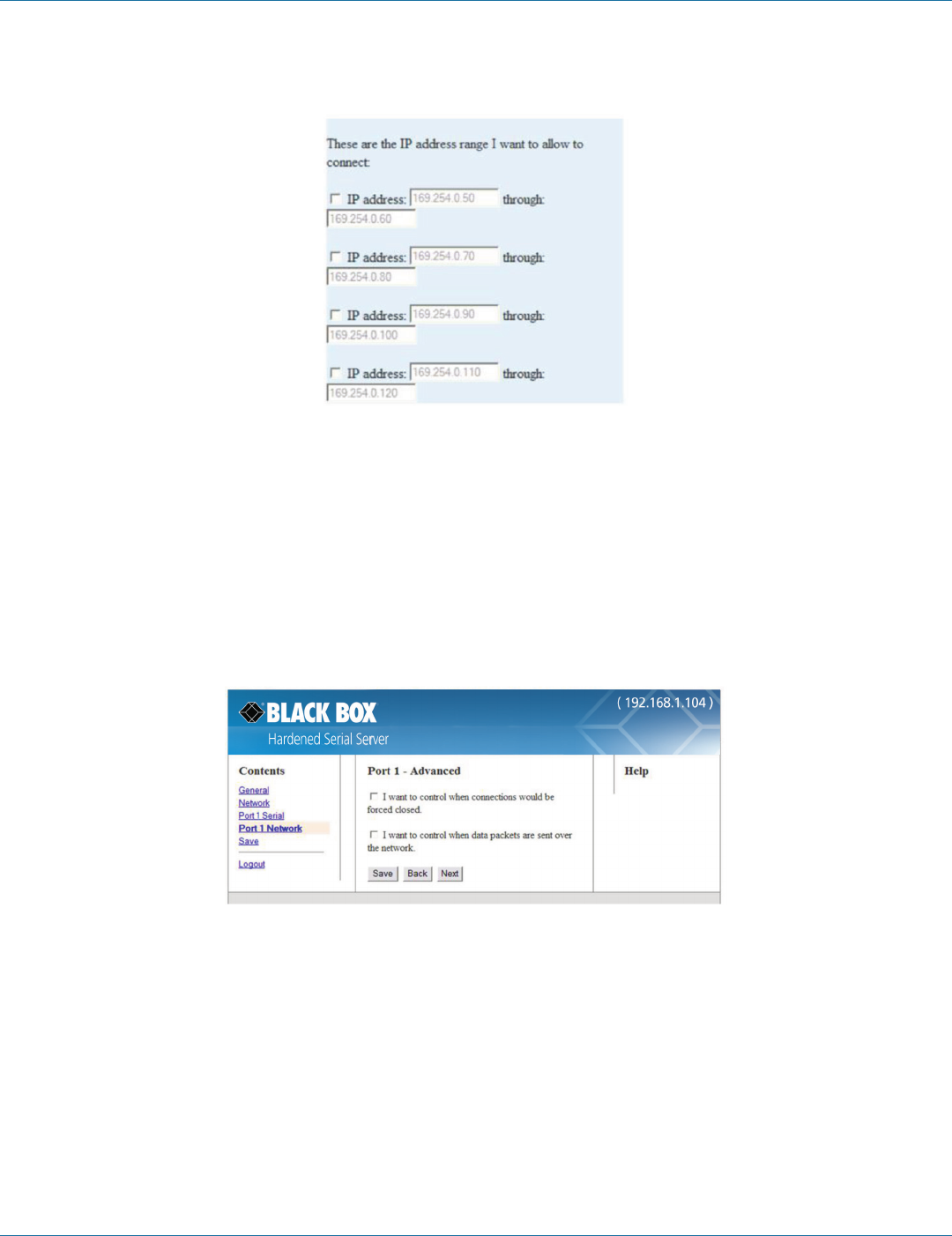
• “and allow a specific range of IP addresses to connect,” in the area of the window that appears, select an IP address box and
type in the IP addresses that specify the desired range.
Figure 4-17. IP address ranges.
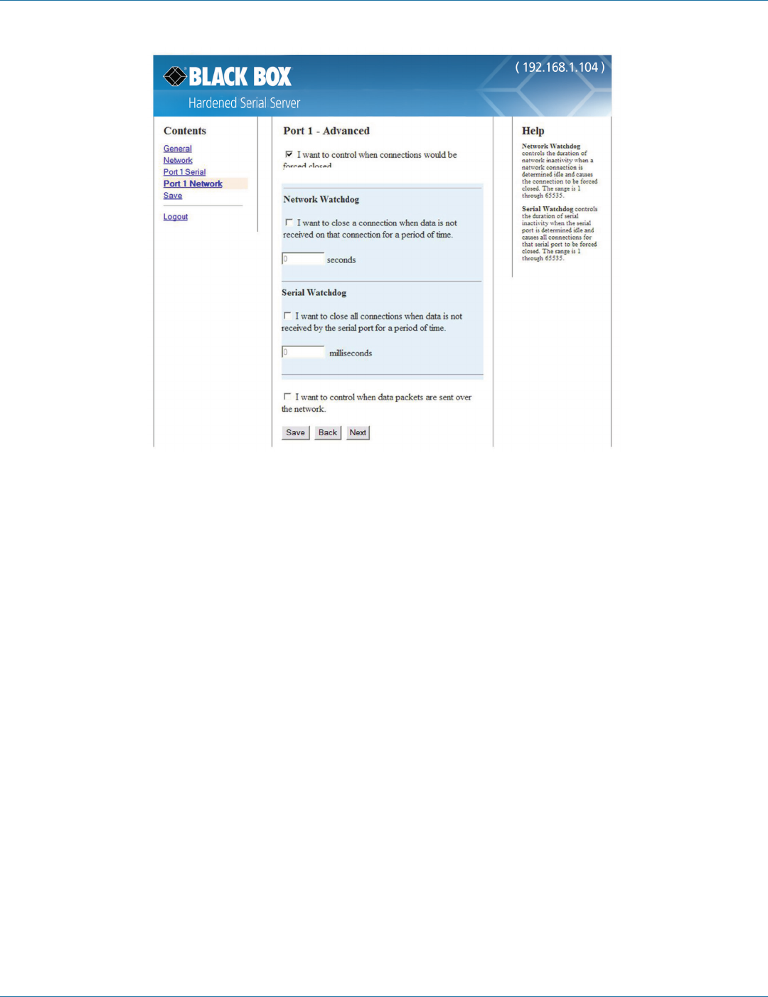
4.8 Setting Up Advanced Network Settings
On the “Advanced Network Settings” window, you can configure if network connections are automatically closed due to
inactivity and when serial data is forwarded to the network.
Data that is received by the serial port is normally buffered for a short period of time and then forwarded over the Ethernet to the
remote device. The Hardened Serial Server automatically optimizes the data buffering to reduce the network overhead and
minimize the data transmission latency. For most applications, the Hardened Serial Server will transmit data back and forth
seamlessly between the end devices. However, certain applications may require additional control over this process. In these cases,
the “Advanced Port Settings” can be used to fine-tune the Hardened Serial Server performance.
Figure 4-18. Advanced Network Settings Window with nothing selected.
4.8.1 Configuring When Network Connections will be Forced Closed
1. Select the “I want to control when connections would be forced closed” checkbox.
The “Network Watchdog” and “Serial Watchdog” configuration boxes appear.
724-746-5500 | blackbox.com
724-746-5500 | blackbox.com Page 35
Chapter 4: Configuring the Hardened Serial Server
Figure 4-19. Advanced configuration—forcing connections closed.
To close a network connection if no data is received from the network for a period of time:
1. Select the “I want to close a connection when data is not received on that connection for a period of time” checkbox.
2. Type the desired time period (in seconds) into the text box.
To close a connection if no data is received by the serial port for a period of time:
1. Select the “I want to close all connections when data is not received by the serial port for a period of time” checkbox.
2. Type the desired time period (in milliseconds) into the text box.
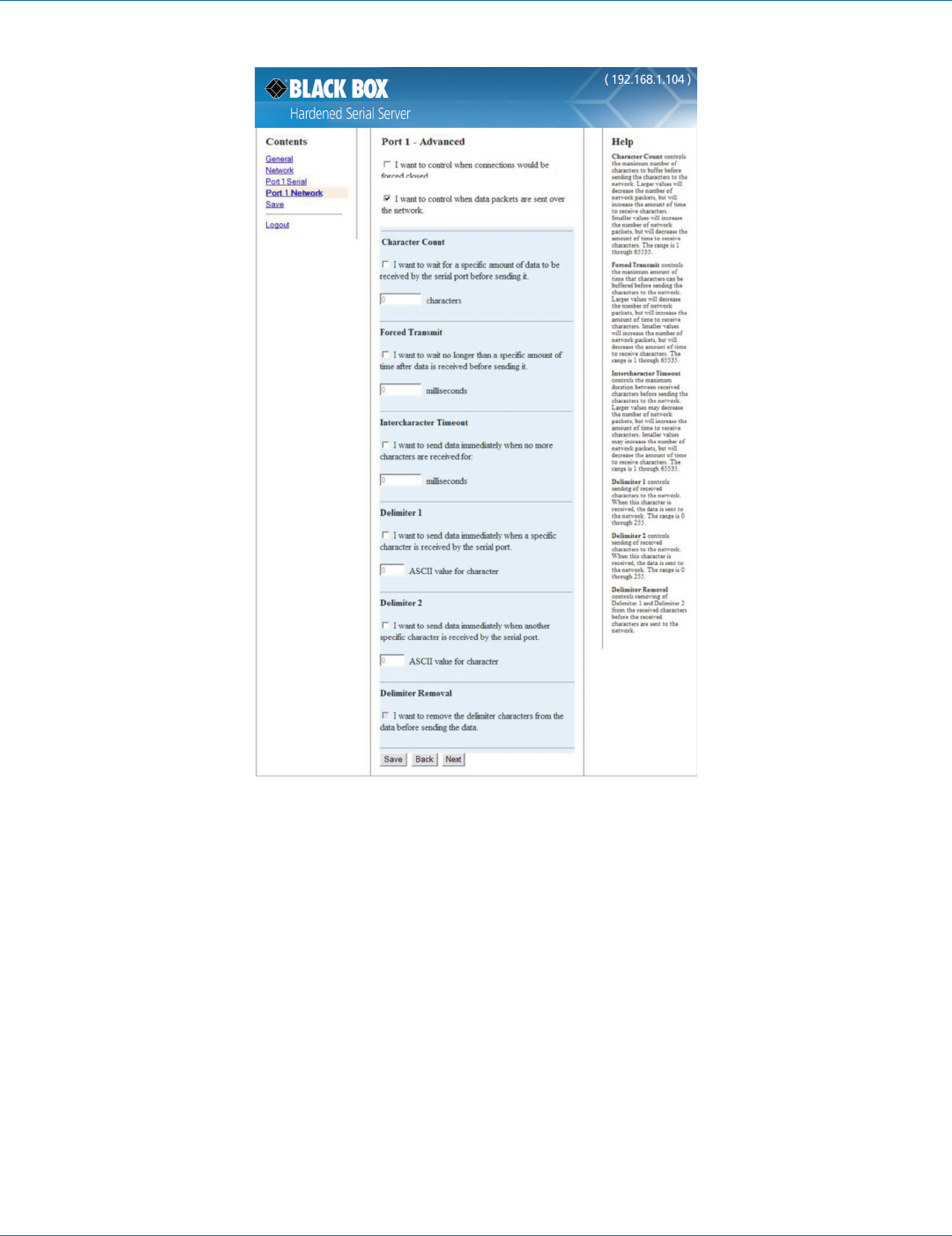
4.8.2 Configuring when Data Packets are Sent
1. Select the “I want to control when data packets are sent over the network” checkbox.
The “Character Count,” “Forced Transmit,” “Intercharacter Timeout,” “Delimiter 1,” “Delimiter 2,” and “Delimiter Removal”
configuration boxes appear.
724-746-5500 | blackbox.com
Page 36
724-746-5500 | blackbox.com
Chapter 4: Configuring the Hardened Serial Server
Figure 4-20. Advanced Configuration—Configuring when data packets are sent.

724-746-5500 | blackbox.com
724-746-5500 | blackbox.com Page 37
Chapter 4: Configuring the Hardened Serial Server
To wait until a specific amount of data is received on the serial port before sending it across the network:
1. Select “I want to wait for a specific amount of data to be received by the serial port before sending it” in the “Character
Count” box.
2. Type the desired number of characters into the text box.
To force the Hardened Serial Server to send all buffered data received on the serial port within a specified length of
time:
1. Select “I want to wait no longer than a specific amount of time after data is received before sending it” in the “Forced
Transmit” box.
2. Type the desired time period (in milliseconds) into the text box.
To force the Hardened Serial Server to send buffered data if another character is not received within a certain period
of time:
1. Select “I want to send data immediately when no more characters are received for” in the “Intercharacter Timeout” box.
2. Type the desired time period (in milliseconds) into the text box.
To force the Hardened Serial Server to start buffering data only when it receives a specified ASCII character on its
serial port:
1. Select “I want to send data immediately when a specific character is received by the serial port” in the “Delimiter 1” box.
2. Type the decimal value for the ASCII character into the text box. For instance, if you want to send data when a “$” is received,
enter “36” into the text box.
NOTE: If Delimiter 1 is selected, Delimiter 2 must also be used.
To force the Hardened Serial Server to send its buffered data when it receives a specified ASCII character on its serial
port:
1. Select “I want to send data immediately when another specific character is received by the serial port” in the “Delimiter 2”
box.
2. Type the decimal value for the ASCII character into the text box. For instance, if you want to send data when a “$” is received,
enter “36” into the text box.
To force the Hardened Serial Server to remove the delimiter characters from the received data when it sends it on to
the Ethernet network:
Select “I want to remove the delimiter characters from the data before sending the data.”
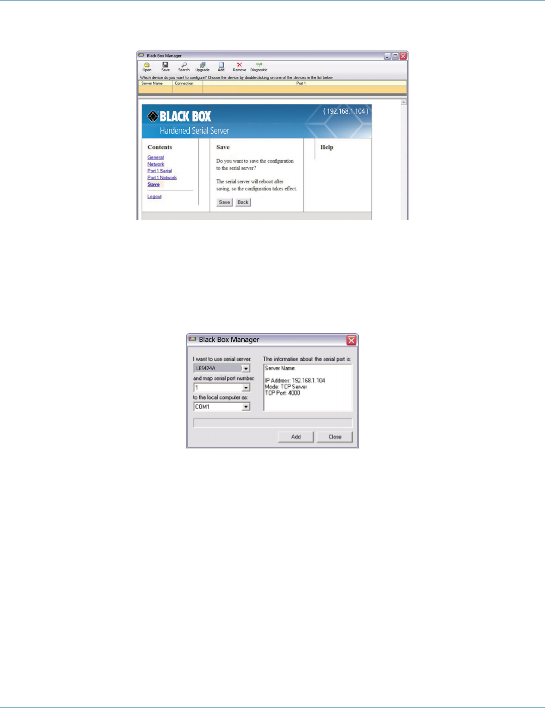
4.9 Saving/Restoring the Configuration Settings
When all configuration windows are complete, the “Save Configuration” page appears.
724-746-5500 | blackbox.com
Page 38
724-746-5500 | blackbox.com
Chapter 4: Configuring the Hardened Serial Server
Figure 4-21. Save Configuration page.
To save the configuration to the Hardened Serial Server, and re-boot it so that the configuration settings will take
effect:
1. Click “Save.”
4.10 Adding Virtual COM Ports
Clicking the “Add” icon (located at the top of the Hardened Serial Server Software Configuration window) opens the Add Virtual
COM Port dialog box.
Figure 4-22. Add Virtual COM Port dialog box.
Using the drop-down boxes, you can select the Hardened Serial Server you want to map the virtual COM port to, the number of
the serial port on the Hardened Serial Server, and the COM port on the local computer. The information box displays the server
name, its IP address, operating mode, and TCP port.
1. On the Hardened Serial Server Software window, click the “Add” icon.
The “Add Virtual COM Port” dialog box appears.
2. Select the Hardened Serial Server to which you want to map the virtual COM port.
3. Select the serial port number on the Hardened Serial Server.
4. Select the COM port number you want to use on the local computer.
5. Click the “Add” button.
724-746-5500 | blackbox.com
724-746-5500 | blackbox.com Page 39
Chapter 4: Configuring the Hardened Serial Server
When the process of adding the virtual COM port is complete (indicated by the progress bar), the “Serial port is successfully
installed” dialog box appears.
6. Click “OK.”
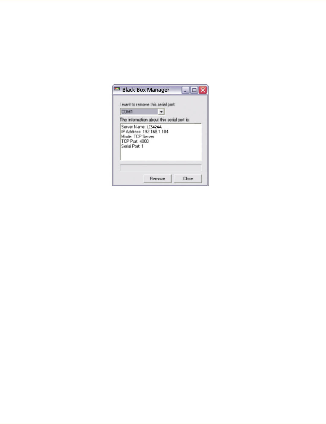
4.11 Removing Virtual COM Ports
Clicking the “Remove” icon (located at the top of the Hardened Serial Server Software Configuration window) opens the
“Remove Virtual COM Port” dialog box.
Figure 4-23. Remove Virtual COM Port dialog box.
Using the drop-down box, you can select the virtual COM port on the local computer. The information box displays the server
name, its IP address, operating mode, and TCP port.
1. Click the “Remove” icon.
The “Remove Virtual COM Port” dialog box appears.
2. Select the COM port number you want to remove from the local computer.
3. Click the “Remove” button.
When the process of removing the virtual COM port is complete (indicated by the progress bar), the “Serial port is successfully
deleted” dialog box appears.
4. Click “OK.”
724-746-5500 | blackbox.com
Page 40
724-746-5500 | blackbox.com
Chapter 5: Upgrading the Hardened Serial Server Firmware
5. Upgrading the Hardened Serial Server Firmware
Occasionally, updated firmware may become available for your Hardened Serial Server. The firmware can be upgraded using the
Hardened Serial Server Software. The following procedure describes the firmware updating process:
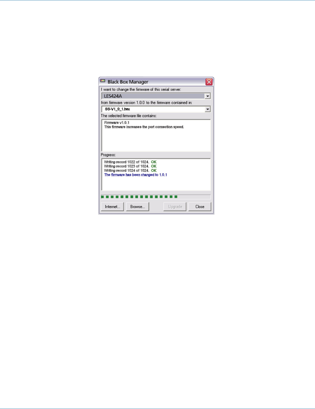
1. Click the “Upgrade” button to open the Firmware Upgrade window.
Figure 5-1. Firmware Upgrade dialog box.
The name of the currently selected Hardened Serial Server appears in the top drop down list. Other Hardened Serial Servers (that
have already been discovered) can be selected from the drop-down list, if desired.
The current firmware version of the selected Hardened Serial Server is shown in the text below the Hardened Serial Server name.
Information about the selected firmware file is shown in the third text box.
5.1 Downloading Firmware Files
The “Firmware File” list (second box) displays all firmware files in the firmware installation folder. Only firmware that is compatible
with the selected Hardened Serial Server is available in this list.
To download the latest firmware files from an FTP site on the Internet:
1. Click the “Internet” button at the bottom of the window.
The Hardened Serial Server Software connects to an FTP server on the Internet.
2. Click the “Check for Updates” button.
“Progress Bar” and “Progress Box” display information about and progress of the download.
To download the latest firmware files from a file:
1. Click the “Browse” button to open an “Open File” dialog box.
2. Browse to the drive and folder containing the firmware file.
3. Select and download the file to the local firmware folder.

724-746-5500 | blackbox.com
724-746-5500 | blackbox.com Page 41
Chapter 5: Upgrading the Hardened Serial Server Firmware
5.2 Uploading the Firmware to the Hardened Serial Server
1. In the “Hardened Serial Server Selection” drop-down list, select the Hardened Serial Server to be upgraded.
2. In the ”Firmware Description” drop-down list, select the firmware to upload to the Hardened Serial Server.
3. Click the “Upgrade” button.
“Progress Bar” and “Progress Box” provide information on the progress of the transfer.
4. In the “Firmware File” drop-down list, select the firmware file to upload to the Hardened Serial Server.
5. Click “Upgrade.”
The Progress box and Progress bar display information on the upgrading process.
6. When the upgrade process is complete, click “Close.”

724-746-5500 | blackbox.com
Page 42
724-746-5500 | blackbox.com
Chapter 6: Operation
6. Operation
6.1 LED Indicators
Hardened Serial Servers have LED indicators for Power, Serial Server Ready, Ethernet Speed and Link status, and Serial Port status.
Figures 6-1 through 6-3 show the location of the LEDs on the LES421A, LES422A, and LES424A servers.
2
3
1
4
Figure 6-1. Front and top panels of the LES421A.
Table 6-1. LEDs and switches on the LES421A serial server.
Number in Figure
6-1 LED Indicator Description
1(1) Serial Port LED (P1) The serial port has an associated LED. The Serial Port LED flashes (green) when data is being transmitted
or received on the serial ports. When the LED is illuminated, it indicates the serial port is open.
2(1) Ready LED
The Ready LED (green) illuminates continuously while the unit is initializing. It flashes once per second
when the system is operating correctly. If the LED is not flashing, it indicates that something is wrong
(e.g., another device on the network at the same IP address).
3(1) Ethernet Link LED
Lights when a connection is made.
Flashes when there is data traffic on the Ethernet link.
4(1) Reset switch A recessed momentary Reset switch is located on the side of the enclosure. To activate the switch,
insert a small plastic tool through the hole in the enclosure and press lightly.
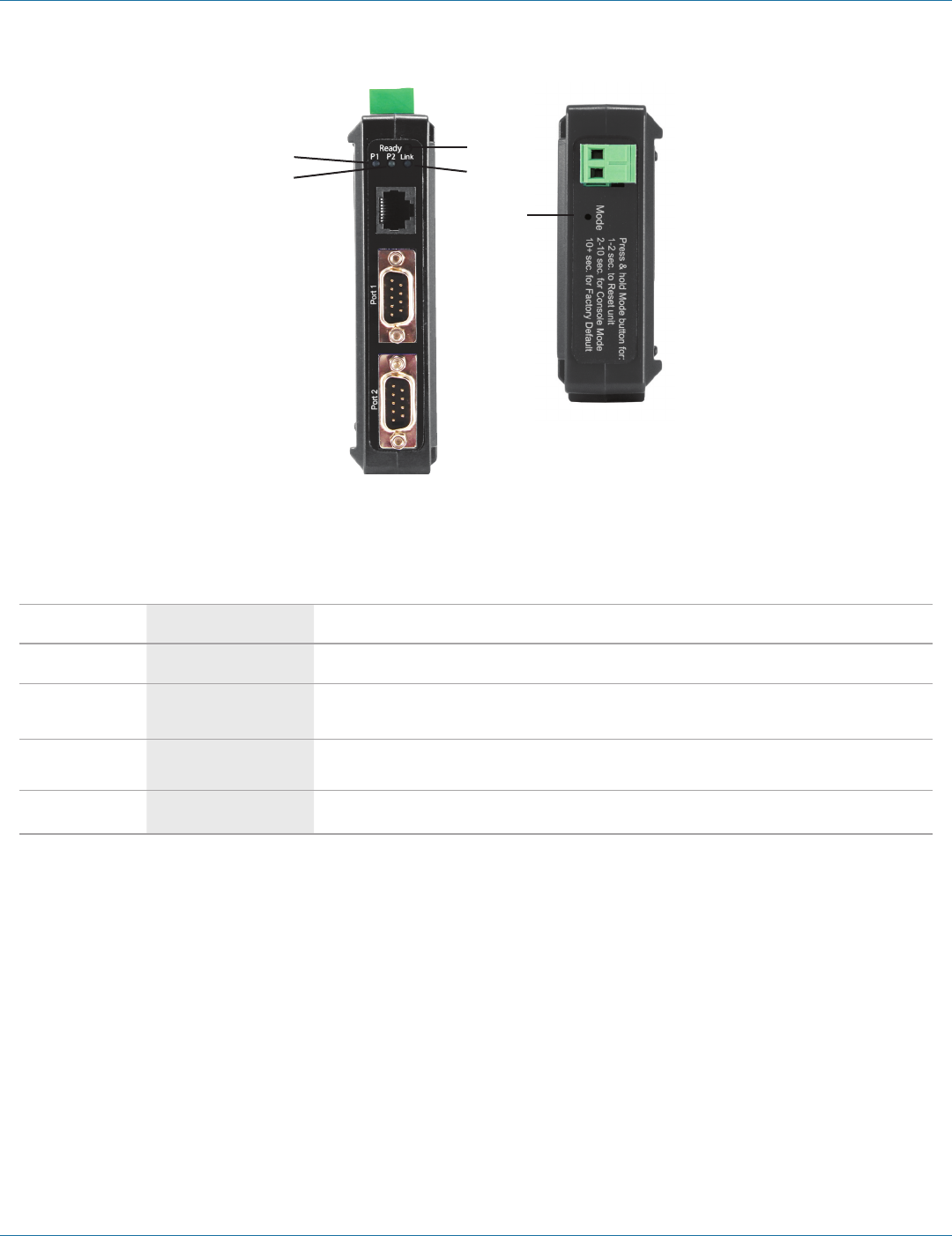
724-746-5500 | blackbox.com
724-746-5500 | blackbox.com Page 43
Chapter 6: Operation
1
1
2
3
4
Figure 6-2. Front panel of the LES422A.
Table 6-2. LEDs and switches on the LES422A serial server.
Number in Figure
6-2 LED Indicator Description
1(2) Serial Port LEDs (P1, P2) Each serial port has an associated LED. The Serial Port LED flashes (green) when data is being
transmitted or received on the serial ports. When the LED is illuminated, it indicates the serial port is open.
2(1) Ready LED
The Ready LED (green) illuminates continuously while the unit is initializing. It flashes once per second when the
system is operating correctly. If the LED is not flashing, it indicates that something is wrong (e.g., another device on
the network at the same IP address).
3(1) Ethernet Link LED
Lights when a connection is made.
Flashes when there is data traffic on the Ethernet link.
4(1) Reset switch A recessed momentary Reset switch is located on the side of the enclosure. To activate the switch, insert a small
plastic tool through the hole in the enclosure and press lightly.
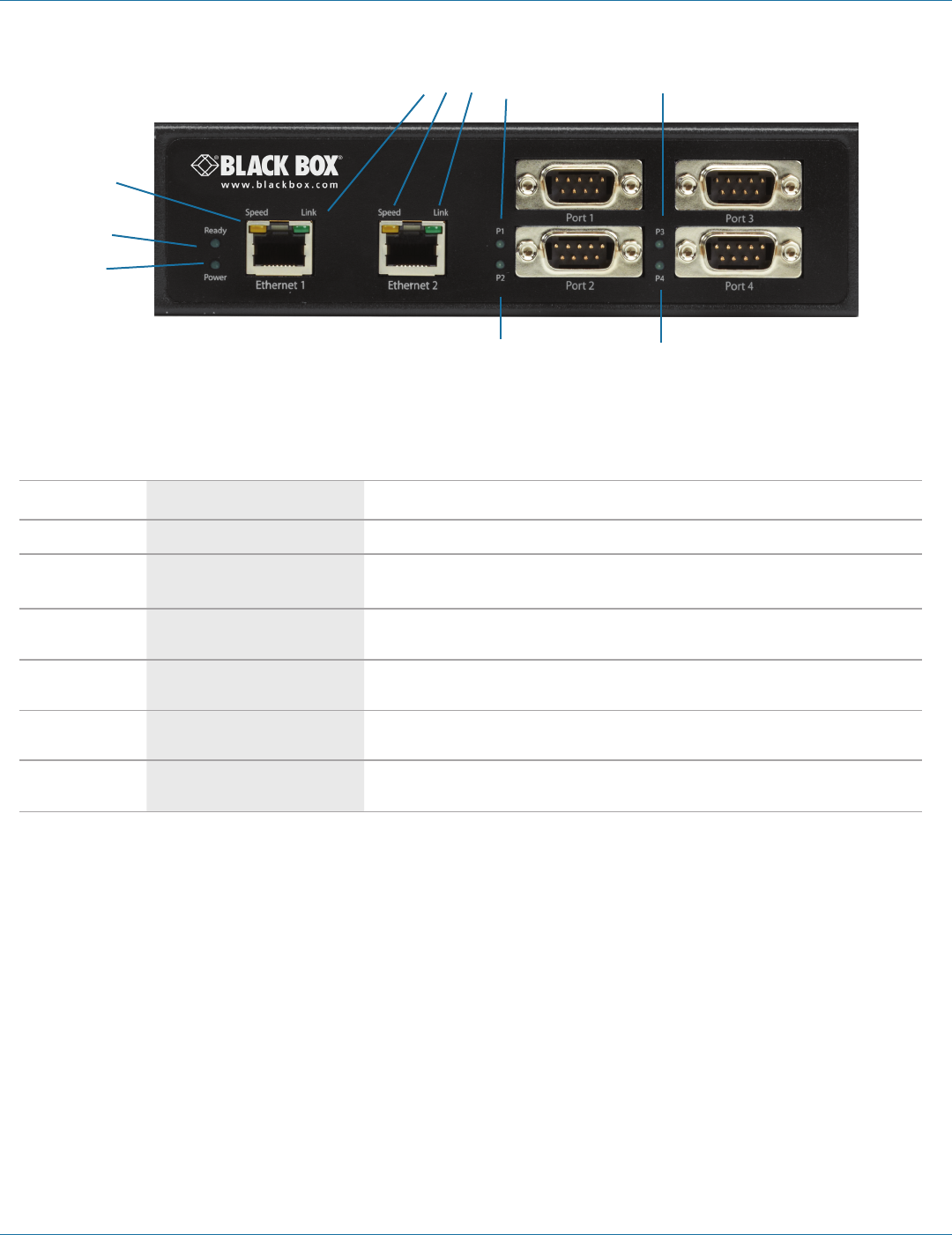
724-746-5500 | blackbox.com
Page 44
724-746-5500 | blackbox.com
Chapter 6: Operation
5 5
3
2
1
4 3 4 5 5
Figure 6-3. Front panel of the LES424A.
Table 6-3. LEDs on the LES424A serial server.
Number in Figure
6-3 LED Indicator Description
1(1) Power LED The Power LED illuminates when 10 to 58 VDC power is applied to either power connector.
2(1) Ready LED The Ready LED (green) illuminates continuously while the unit is initializing. It flashes once per second
when the system is operating correctly. If the LED is not flashing, it indicates that something is wrong
(e.g. another device on the network at the same IP address).
3(2) Ethernet Speed LEDs
Lights green when the Ethernet connection is operating at 100 Mbps.
Off when the connection is operating at 10 Mbps.
4(2) Ethernet Link LEDs
Lights when a connection is made.
Flashes when there is data traffic on the Ethernet link.
5 (4) Serial Port LEDs (P1, P2, P3, and P4) Each serial port has an associated LED. Serial Port LEDs flash (green) when data is being transmitted or
received on the serial ports. When the LED is illuminated, it indicates the serial port is open.
6(1) Reset switch A recessed momentary Reset switch is located on the side of the enclosure. To activate the switch,
insert a small plastic tool through the hole in the enclosure and press lightly.
NOTE: LEDs on the Hardened Serial Server are also used to indicate various Reset modes, as described in the following section.
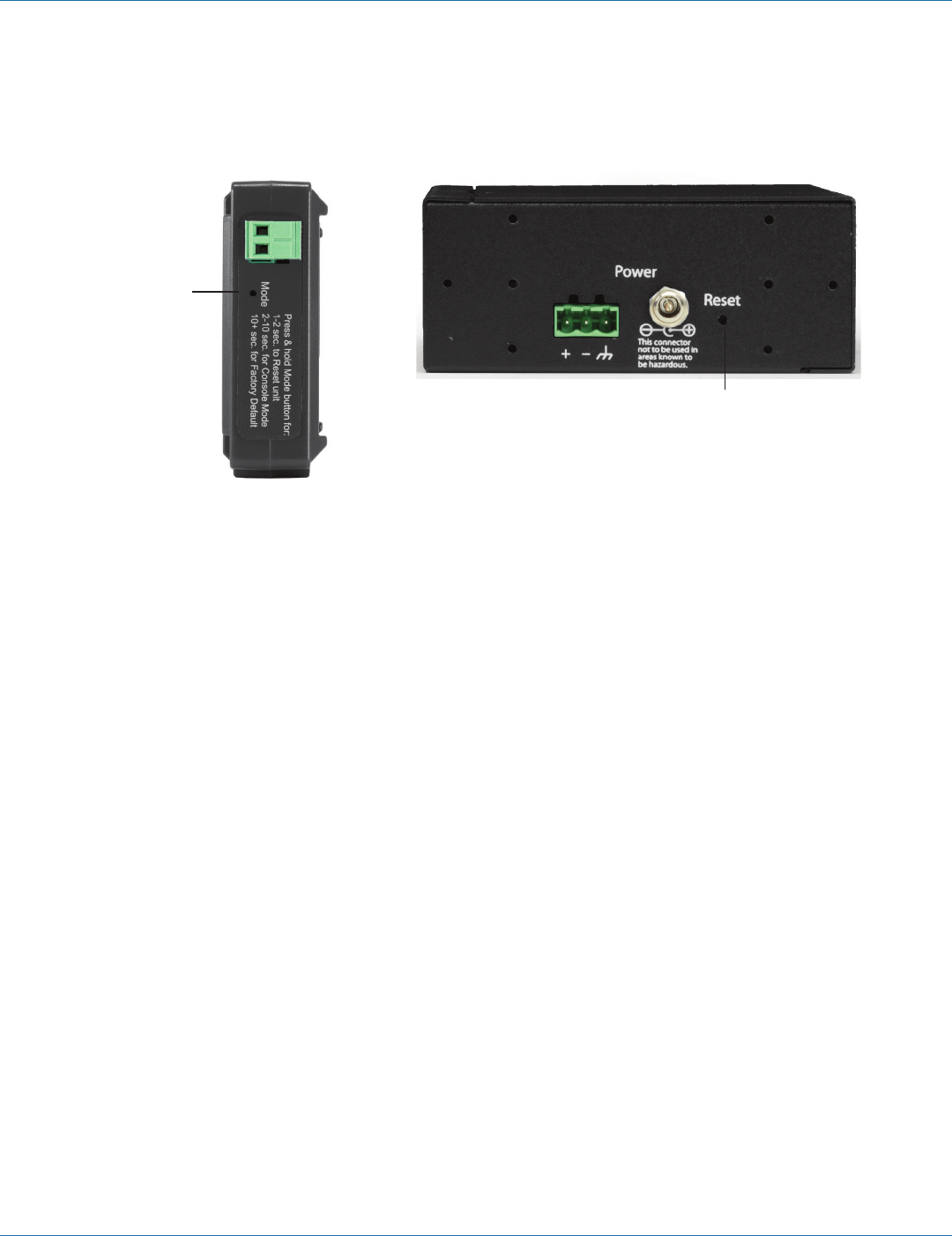
724-746-5500 | blackbox.com
724-746-5500 | blackbox.com Page 45
Chapter 6: Operation
6.2 Reset Switch
Figure 6-4 shows the location of the Reset switch on the LES421A, LES422A, and LES424A Hardened Serial Servers.
Reset Switch
Reset Switch
Figure 6-4. Left: top view of the LES421A or LES422A; Right: back view of the LES424A.
The Reset switch is used to:
• Initiate a hardware reset.
• Enter Console mode.
• Reload factory defaults.
6.2.1 Using the Reset Switch to Initiate a Hardware Reset
Hold the Reset switch in for 0 to 2 seconds. The P1 LED illuminates while the switch is being held in. Release the switch in less
than two seconds or the Hardened Serial Server will enter Console Mode.
6.2.2 Using the Reset Switch to Enter Console Mode
Hold the Reset switch for between two and ten seconds. The P1 LED illuminates for the first two seconds and the P1 LED goes
out, then the P2 LED illuminates until the Reset switch is released. Release the switch in less than 10 seconds or the Hardened
Serial Server will reset to factory default settings. The Hardened Serial Server will re-boot and enter Console Mode. LED P1 will be
on while the unit is in Console Mode.
6.2.3 Using the Reset Switch to Exit Console Mode
Press the Reset switch for less than two seconds, or remove power from the Hardened Serial Server, wait a few seconds, and turn
the power on again. The LEDs go back to their normal states when the device resumes normal operation.
6.2.4 Using the Reset Switch to Reload Factory Default Settings
Hold the Reset switch for more than ten seconds. The P1 LED illuminates for the first two seconds; then the P2 LED illuminates.
After 10 seconds the P1 and P2 LEDs will illuminate. When the switch is released, both the P1 and P2 LEDs will go out. The Ready
LED will flash quickly while the Hardened Serial Server re-initializes to factory default settings, and then the server will re-boot.
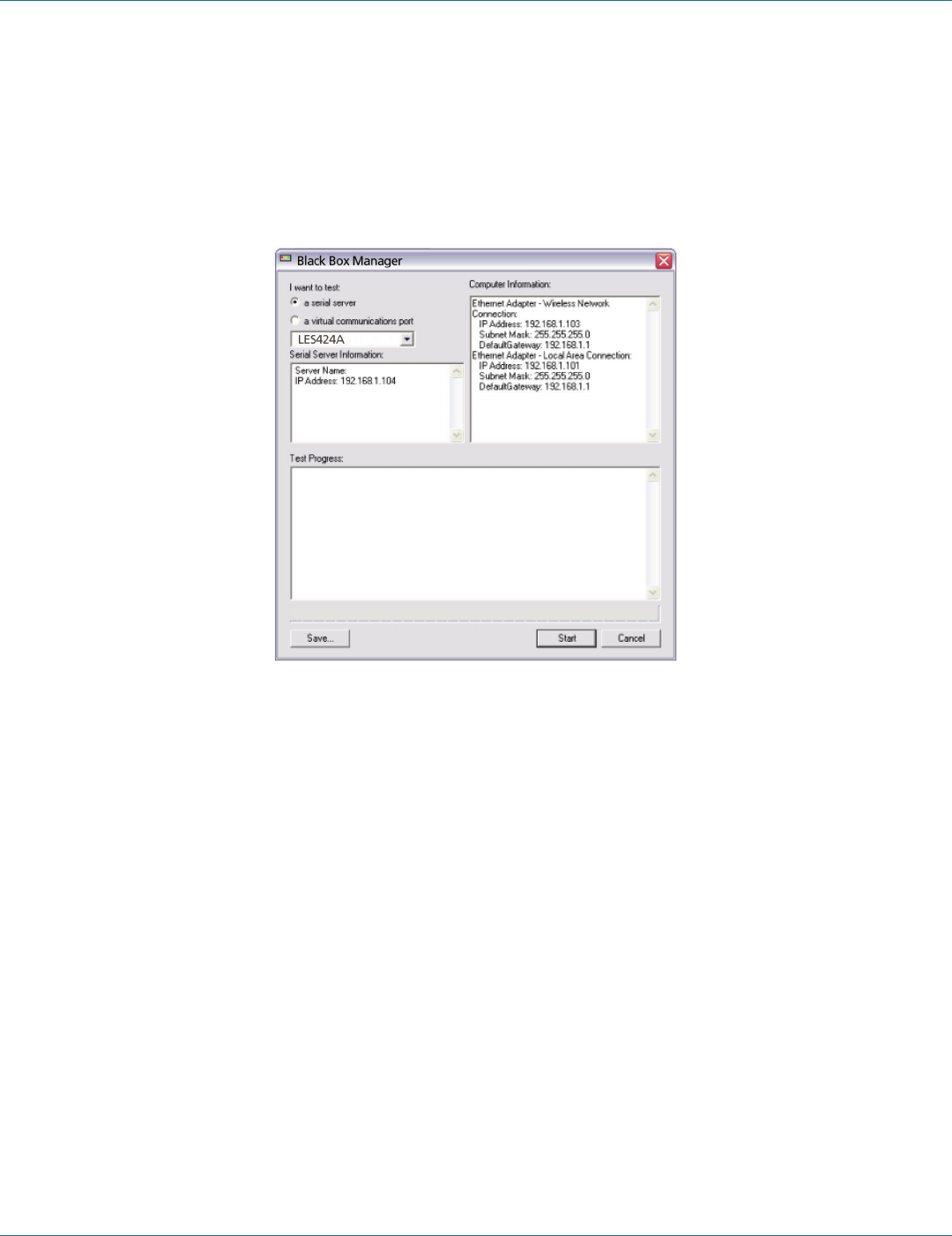
724-746-5500 | blackbox.com
Page 46
724-746-5500 | blackbox.com
Chapter 7: Diagnostics
7. Diagnostics
Clicking the “Diagnostics” icon opens the Diagnostics dialog box and enables you to check the operation of connected serial
servers and VCOM ports on the local computer.
The Computer Information box displays information about the type of network connections, the IP addresses, Subnet Masks, and
Default Gateways in use.
Figure 7-1. Diagnostics dialog box.
7.1 Testing a Hardened Serial Server Connection
1. Click the “Diagnostics” icon.
The “Diagnostics” dialog box appears.
2. Select the option: “a serial server”
3. In the drop-down box, select the specific serial server you want to check.
4. Click the “Start” button.
Information about the progress of the pinging process is displayed in the “Test Progress” box.
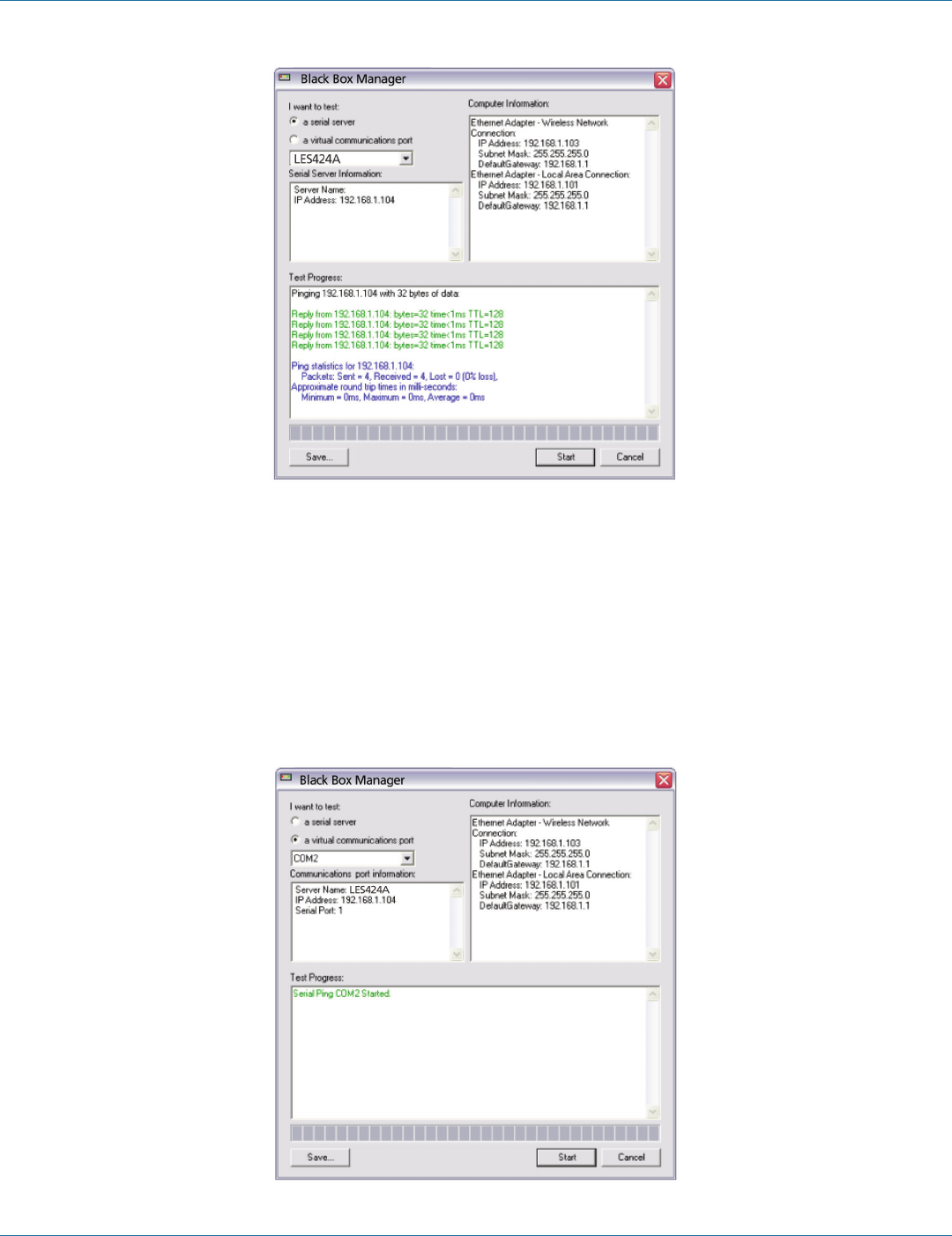
724-746-5500 | blackbox.com
724-746-5500 | blackbox.com Page 47
Chapter 7: Diagnostics
Figure 7-2. Testing a Hardened Serial Server Connection.
7.2 Testing a Virtual COM Port
1. Click the “Diagnostics” icon.
The “Diagnostics” dialog box appears.
2. Select the option: “a virtual communications port”
3. In the drop-down box, select the specific COM port you want to check.
4. Click the “Start” button.
Information about the progress of the pinging process is displayed in the “Test Progress” box.
Figure 7-3. Testing a VCOM port.

724-746-5500 | blackbox.com
Page 48
724-746-5500 | blackbox.com
Chapter 8: Listing/Descriptions of Hardened Serial Server Settings
8. Listing/Descriptions of Hardened Serial Server Settings
The following Hardened Serial Server properties are ordered alphabetically to assist you in finding the information you need.
Baud Rate is the communication speed of the link between the Hardened Serial Server and the device attached to its serial port.
Both devices must be configured to operate at the same baud rate. Baud rate values range from 75 to 230,400 Baud. (Refer to
Chapter 1 for specific baud rates that are supported.)
Character Count controls the maximum number of characters to buffer before sending the characters to the network. Larger
values decrease the number of network packets, but increase the amount of time to receive characters. Smaller values increase
the number of network packets, but decrease the amount of time to receive characters. The range is 1 through 65535.
Configuration files contain all of the configuration settings for the Hardened Serial Server. When the Hardened Serial Server
settings have been configured, you can save the settings using Hardened Serial Server Software. Existing configuration files can be
Opened (from Hardened Serial Server Software), which loads them into the Hardened Serial Server. This allows the same
configuration to be applied to multiple Hardened Serial Servers, or to reload a previously used configuration.
Data/Parity/Stop Bits. The number of Data bits, type of Parity, and number of Stop bits selected define the serial port
parameters at which the Hardened Serial Server will operate. These parameters must be configured to match the parameters set
on the serial device connected to the Hardened Serial Server's serial port.
• Data Bits controls the number of bits of data in each character. Options include 5, 6, 7, or 8 data bits.
• Parity controls the error-checking mode. Options are No Parity, Odd, Even, Mark, or Space.
• Stop Bits controls the number of bits to indicate the end of a character. Options include 1, 1.5, and 2. (1.5 bits is only valid
when 5 data bits is selected, which is rare. The 2 stop bits setting is only valid when 6, 7, or 8 data bits is selected.)
The Default Gateway address sets the default route to remote networks, enabling users to access the Hardened Serial Server
from outside the local network.
Delimiter 1, Delimiter 2, and Delimiter Removal. Delimiters and Delimiter Removal enable you to control how characters
received on a serial port are sent across the network. Delimiters are ASCII characters specified by the user when configuring the
Hardened Serial Server. The Hardened Serial Server takes action when it recognizes the specified character(s) on its serial port.
• Delimiter 1 is a start delimiter. The range of ASCII values is 0 through 255.
• Delimiter 2 is an end delimiter. The range of ASCII values is 0 through 255.
• Delimiter Removal controls removing of Delimiter 1 and Delimiter 2 from the received characters before the received
characters are sent to the network.
How Delimiters Work. When only Delimiter 2 (the end delimiter) is enabled, characters received by the serial port are
accumulated in a buffer. When the end delimiter is received on the serial port, the buffered characters, including the end
delimiter, are sent to the network. All characters received after the end delimiter are again buffered until another end delimiter
is received.
When both Delimiter 1 (start delimiter) and Delimiter 2 (end delimiter) are enabled, characters received by the serial port will be
discarded until the start delimiter character is detected on the serial port. The Hardened Serial Server then buffers the start
delimiter character and all subsequent characters received after it until the end delimiter is detected. When the end delimiter is
received, the buffered characters, including the start and end delimiters, are sent to the network.
When Delimiter Removal is enabled, the Hardened Serial Server removes the delimiter character(s) before sending the other
characters across the network.

724-746-5500 | blackbox.com
724-746-5500 | blackbox.com Page 49
Chapter 8: Listing/Descriptions of Hardened Serial Server Settings
Dynamic Host Configuration Protocol (DHCP) is a protocol used on special servers that supply IP addresses to network nodes
on request.
When DHCP is enabled on the Hardened Serial Server, on power up it sends a DHCP request to the DHCP server, which assigns a
dynamic IP address, subnet mask, and default gateway to the Hardened Serial Server.
When DHCP is disabled (static IP addressing), the IP Address, Subnet Mask and Default Gateway fields must be set manually by
entering the appropriate addresses in these fields. If you do not know what addresses to use in these fields, ask your network
administrator.
NOTES:
1. This product is factory-defaulted to the DHCP mode. Your network’s DHCP Server is expected to provide the IP address
assignment. If there is not a DHCP server on your network, the device will default to IP address 169.254.102.39.
2. A dynamic address assigned by the DHCP server may change if the server loses the Ethernet connection or power is removed.
If a device on the network that normally communicates with the Hardened Serial Server is configured to communicate with a
specific IP address of the Hardened Serial Server, and the IP address has been changed, the device will not be able to
communicate with the Hardened Serial Server.
The Firmware Version number (Vx.x.x) indicates the Hardened Serial Server's currently loaded firmware release. From time to
time new firmware is made available and can be uploaded into the serial server using Hardened Serial Server Software.
Flow Control determines the type of handshaking that is used to control sending and receiving of messages. Options include No
Flow Control, Hardware Flow Control (RTS/CTS) and Software Flow Control (X-ON/X-OFF). The Flow Control setting must match
the requirements of the serial device connected.
NOTE: Select No Flow Control when setting the port as RS-422 or RS-485 4-wire.
Forced Transmit controls the maximum amount of time that characters can be buffered before sending the characters to the
network. Larger values decrease the number of network packets, but increase the amount of time to receive characters. Smaller
values increase the number of network packets, but decrease the amount of time to receive characters. The range is 1 through
65535.
The Hardware Version number of the Hardened Serial Server hardware is displayed on the Login page of the Hardened Serial
Server Software.
Inter-character Timeout controls the maximum duration between received characters before sending the characters to the
network. Larger values may decrease the number of network packets, but increase the amount of time to receive characters.
Smaller values may increase the number of network packets, but decrease the amount of time to receive characters. The range is
1 through 65535.
IP Address. Software or hardware attempting to access the Hardened Serial Server via the network must know the IP Address of
the server. In DHCP mode (factory default), the serial server requests and receives a dynamic IP address from a DHCP server when
it first connects to the network. If there is not a DHCP Server on your network, this device will automatically default to IP Address
169.254.102.39. If the Hardened Serial Server is unable to connect to your network using this address, there are two methods to
manually configure the IP Address.
1. Method One: Change your PC Network to Match the Hardened Serial Server
a. Open the network connection on your PC.
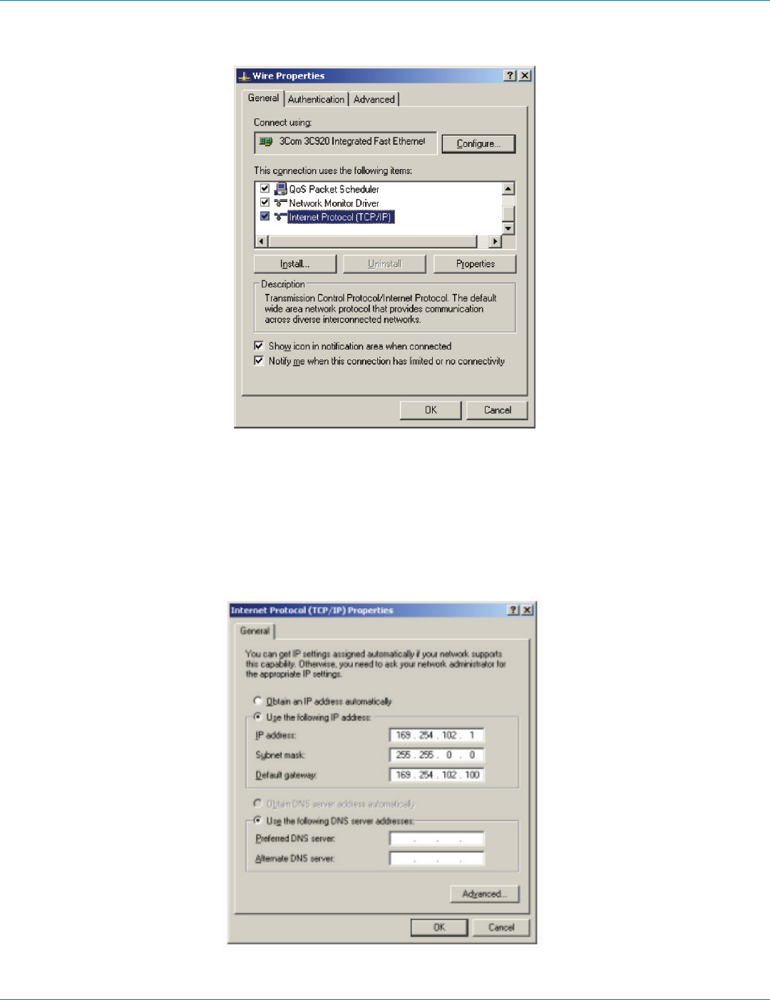
724-746-5500 | blackbox.com
Page 50
724-746-5500 | blackbox.com
Chapter 8: Listing/Descriptions of Hardened Serial Server Settings
Figure 8-1. Network IP properties.
b. Click “Internet Protocol (TCP/IP)” and then click “Properties.” Change the parameters to the following:
• IP Address = 169.254.102.1
• Subnet Mask = 255.255.255.0
• Default Gateway = 169.254.102.100
Figure 8-2. TCP/IP properties.

724-746-5500 | blackbox.com
724-746-5500 | blackbox.com Page 51
Chapter 8: Listing/Descriptions of Hardened Serial Server Settings
c. Use the Hardened Serial Server Software to search for, discover, and configure the unit.
2. Method Two: Change the Hardened Serial Server’s network setting to match your PC using Console mode.
a. Connect a null-modem serial cable (crossover cable) from any port on the Hardened Serial Server to an available COM port on
your PC.
b. Open Hardened Serial Server Software and connect to the COM port used in the previous step. Ensure the port is configured
to 115,200 baud, 8 data bits, and 1 stop bit.
c. Enter Console Mode. Press and hold the serial server’s reset switch for 2 to 10 seconds. The LED indicators will respond as
follows:
Table 8-1. Serial server information table.
Model Port 1 LED Port 2 LED Port 3 LED Port 4 LED Ready LED
1-Port OFF N/A N/A N/A ON
2-Port OFF ON N/A N/A OFF
4-Port OFF ON OFF OFF OFF
d. Release the Reset button. The Ready LED will flash twice per second for 5 seconds. This indicates that the serial server is
re-booting in Console Mode.
e. When the Hardened Serial Server has successfully restarted in Console Mode, the Ready LED will be off and the Port 1 LED will
be on.
f. Open the Hardened Serial Server Software and select “Serial Port” as the method to connect to the device.
g. After logging in, click “Network.”
h. De-select “I want DHCP to setup the Network.”
i. Re-configure the serial server’s network settings to an address within the range of your PC’s network setting.
For example, if your PC is configured to the following settings:
IP Address = 192.168.0.1
Network Mask = 255.255.255.0
Default Gateway = 192.168.0.100
Configure the Hardened Serial Server to:
IP Address = 192.168.0.50
Network Mask = 255.255.255.0
Default Gateway = 192.168.0.100
• Save the settings and remove power from the serial server.
• Apply power to the Hardened Serial Server.
• Open the Hardened Serial Server Software and select “Network” as the method to connect to the Hardened Serial Server.
Link Status of the currently selected Hardened Serial Server is shown on the Login page of Hardened Serial Server Software. Link
status indicates the type of Ethernet connection between the computer and Hardened Serial Server. It will either display 10BASE-T
or 100BASE-TX in full duplex or half duplex. Link status is dependent on the LAN, switches, and hubs used in the LAN topology.
The MAC Address is a hardware level address of the Hardened Serial Server that cannot be changed. It is assigned in the factory.
Every Ethernet device manufactured has its own unique MAC address. The MAC address of each serial server is printed on the
device's label. The MAC address of the currently selected serial server is also displayed on the Login page of Serial Server
Software.

724-746-5500 | blackbox.com
Page 52
724-746-5500 | blackbox.com
Chapter 8: Listing/Descriptions of Hardened Serial Server Settings
The model number of the currently selected Hardened Serial Server is displayed on the Login page of Serial Server Software.
Network Protocols available for use on Hardened Serial Servers (LES421A, LES422A, and LES424A) include TCP, UDP, VCOM,
and Paired Mode.
Network Watchdog controls the duration of network inactivity when a network connection is determined idle and causes the
connection to be forced closed. The range is 1 through 65535 milliseconds.
Paired Mode enables two Hardened Serial Servers to operate across the network like a “wire replacement” between two serial
devices. (Paired Mode is also called serial tunneling.) Serial devices connected to Hardened Serial Servers on each end of the link
can communicate as if they were connected by a serial cable.
• For Paired Mode to work, one Hardened Serial Server must be configured as a TCP server and the other as a TCP client.
• The Hardened Serial Server configured as the TCP client initiates connections. You must set up the IP address and port number
of the server that you want the client (Hardened Serial Server) to communicate with. You also select whether you want the
Hardened Serial Server to connect at power up or only when it receives data from the device connected to its serial port.
• The Hardened Serial Server configured as a TCP server waits for connections to be initiated by another network device. You
must set up the TCP port number on which it will listen for connections and set the maximum (one, up to two, or up to four)
number of simultaneous connections it will accept. You can filter the connections it will accept based on specific IP addresses or
ranges of IP addresses that you specify.
Password. When you first receive the LES421A, LES422A, or LES424A Hardened Serial Server from the factory, the password is
blank so that you can initially access the Hardened Serial Server without entering a value into this field. To ensure security, you
should create and save a password the first time you configure the serial server. After a password has been set up it must be
entered each time you login to Hardened Serial Server Software. The password is used to access the configuration pages from the
Hardened Serial Server Software Login page and can be changed from the General page.
Serial Interface Modes. Four serial interface modes of operation are:
• RS-232—Point-to-point serial communications connection used by PC COM ports and many other systems. Capable of baud
rates up to 115.2 kbaud over short distances (about 50 feet). Typically uses DB9 connectors, but a 5-screw terminal block can
also be used on LES421A serial servers.
• R S - 4 2 2 —Point-to-point communications using a transmit pair and a receive pair. RS-422 can operate at higher speeds and
longer distances than RS-232. Typically uses two shielded twisted pairs and screw terminals but DB9 connectors are used on
LES421A, LES422A, and LES424A serial servers.
• RS-485 2-wire—Similar speed and distance specifications as RS-422, but allows multidrop connections. Typically uses one
shielded twisted pair and screw terminals but DB9 connectors are used on LES421A, LES422A, and LES424A serial servers.
• RS-485 4-wire—Similar speed and distance specifications as RS-422 but allows full-duplex connections. Typically uses two
shielded twisted pairs and screw terminals but DB9 connectors are used on LES421A, LES422A, and LES424A serial servers.
Select the appropriate serial interface mode for the type of connection between the Hardened Serial Server’s serial port and the
device connected to it.
NOTE: Refer to Appendix B for connector and pinout details.
Hardened Serial Server Name is a unique name assigned to the serial server. It must be a valid hostname as defined by
RFC-952 and RFC-1123. The rules are:
• It must consist only of the characters “A” to “Z,” “a” to “z,” “0” to “9,” or “-”
• It can start or end with a letter or a number, but it must not start or end with a “-”
• It must not consist of all numeric values.
The Server Serial Port Number of the currently selected port is shown in this field. For more information, refer to the TCP/UDP
Ports table in Section 1.4, which shows the ports used for several modes of operation.

724-746-5500 | blackbox.com
724-746-5500 | blackbox.com Page 53
Chapter 8: Listing/Descriptions of Hardened Serial Server Settings
Serial Watchdog controls the duration of serial inactivity when the serial port is determined idle and causes all connections for
that serial port to be forced closed. The range is 1 through 65535 milliseconds.
The Subnet Mask specifies the network mask the Hardened Serial Server uses when on a subnetted network.
• For a Class A network (IP addresses 0.0.0.0 through 127.255.255.255), the default subnet mask is 255.0.0.0.
• For a Class B network (IP addresses 128.0.0.0 through 191.255.255.255), the default subnet mask is 255.255.0.0.
• For a Class C network (IP addresses 192.0.0.0 through 233.255.255.255), the default subnet mask is 255.255.255.0.
• For a Class D network (IP addresses 224.0.0.0 through 239.255.255.255) and Class E Networks (IP addresses 240.0.0.0 through
255.255.255.255), the subnet mask is ignored.
• LES421A, LES422A, and LES424A servers come from the factory with a default subnet mask value of: 255.255.255.0.
Transmission Control Protocol (TCP) provides reliable connection-oriented network communication with error checking. In TCP
mode the Hardened Serial Server can be configured as a client or a server.
TCP client. When the Hardened Serial Server is configured as a TCP client, it initiates connections with a server on the network.
You must set up the IP address and port number of the server that you want the client (serial server) to communicate with. You
also select whether the Hardened Serial Server is to connect at power up or only when it receives data from the device connected
to its serial port.
TCP server. When the Hardened Serial Server is configured as a TCP server it waits for connections to be initiated by another
network device. You must set up the TCP port number that it will listen to for connections and set the maximum (one, up to two,
or up to four) number of simultaneous connections it will accept. You can filter the connections it will accept based on specific IP
addresses or ranges of IP addresses that you specify.
User Datagram Protocol (UDP) enables applications using UDP socket programs to communicate with the serial ports on the
serial server. UDP protocol provides connectionless communications, which allows data to be broadcast to and received from
multiple nodes on a network. (Because it is a connectionless protocol, UDP does not guarantee the delivery of a datagram and
the datagram is only sent once.)
• In UDP mode, if you want to control what network node receives data, you must specify the IP address and UDP port the data
will be sent to. You can choose to send to:
- Nobody
- All nodes at a specific UDP port number. (This is called broadcast.)
- Specific IP addresses and UDP port numbers. (This is called unicast.)
- A range of IP addresses and UDP port numbers. (This is called unicast range.)
• You can also configure the Hardened Serial Server to receive from nodes on the network using the same list of configuration
options.
In VCOM (Virtual COM Port) mode the Hardened Serial Server communicates over the network with a PC, acting as a remote
COM port for the computer.
Both the Hardened Serial Server and the computer must be configured for VCOM operation. Virtual COM ports can be set up on
the PC using the Serial Server Software.

724-746-5500 | blackbox.com
Page 54
724-746-5500 | blackbox.com
Appendix A: Default Server Settings
Appendix A. Default Server Settings
Table A-1. Default server settings.
Setting Default Value
Server Name LES421A, LES422A, or LES424A
Serial Number Printed on side of unit.
Password Password field is blank from factory.
DHCP Enable
IP Address BASED ON DHCP SERVER
If a DHCP assignment is not available, the device will default to 169.254.102.39
Net Mask 255.255.255.0
Gateway 169.254.102.10 0
MAC Address Fixed—see bottom label
Firmware Version X.X.X (Current Version)
Hardware Version X.X (Current Version)
Port 1, 2, 3, 4
Serial port mode RS-232
Baud Rate 9600
Data bits 8
Parity None
Stop bits 1
Flow Control None
Protocol TCP
Serial timeout 0 seconds
TCP alive timeout 0 minutes
Connection Mode Server
Delimiter HEX 1 00
Delimiter HEX 2 00
Remove delimiters Disable
Force transmit 0 ms
Inter-character timer 0 ms
Character count 0
Max connection 1
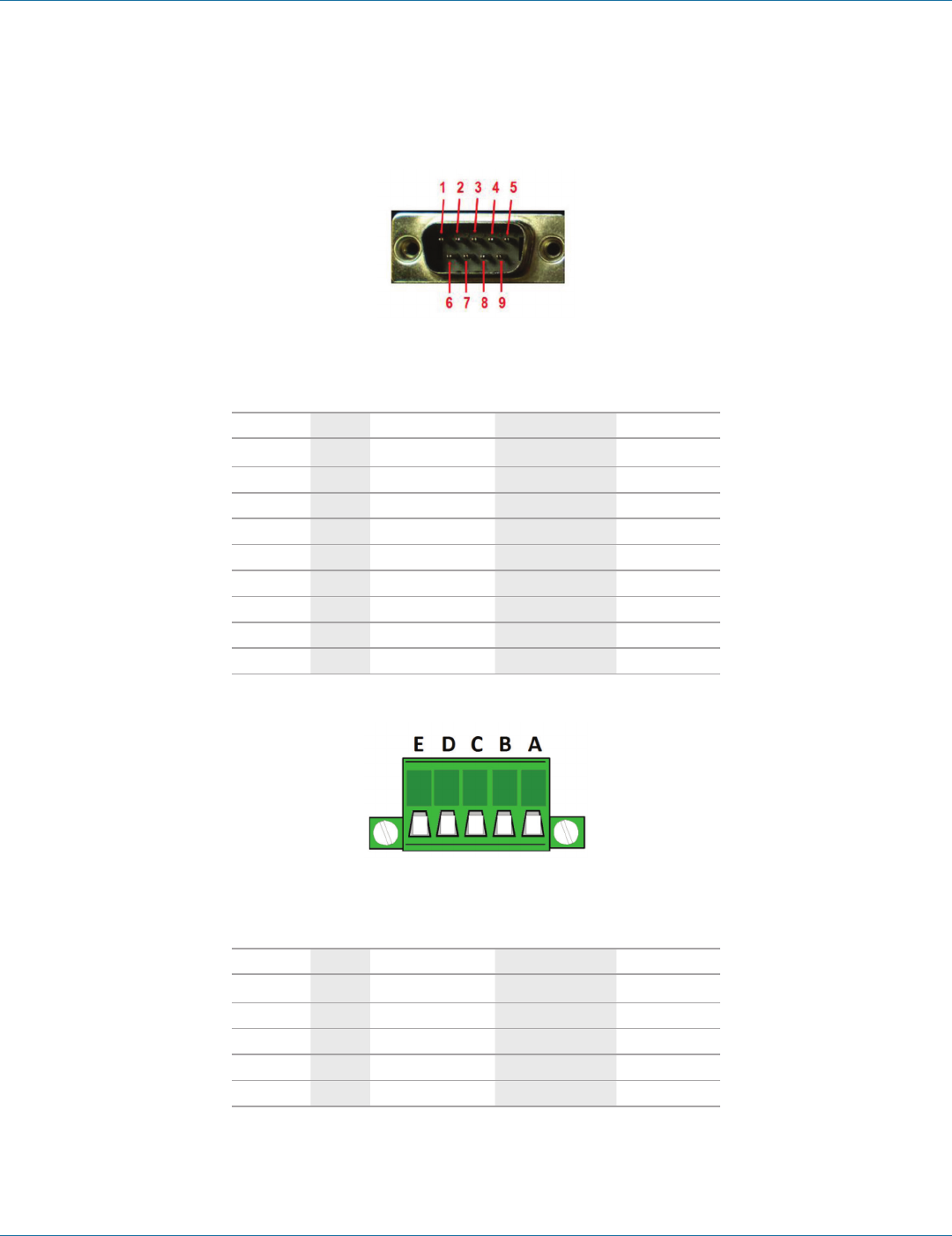
724-746-5500 | blackbox.com
724-746-5500 | blackbox.com Page 55
Appendix B: Connector Pinouts
Appendix B. Connector Pinouts
B.1 DB9 M Connector
Figure B-1. DB9 M connector.
Table B-1. DB9 M connector pinout.
DB9 M Pin RS-232 Direction (RS-232) RS-422/485 4-Wire RS-485 2-Wire
1DCD Input RDA (-) —
2RD Input RDB (+) —
3TD Output TDB (+) Data B (+)
4DTR Output TDA (-) Data A (-)
5GND —GND GND
6DSR Input — —
7 RTS Output — —
8CTS Input — —
9 — — — —
B.2 Terminal Block
Figure B-2. Terminal block connector.
Table B-2. Terminal block connector pinout.
Terminal RS-232 Direction (RS-232) RS-422 RS-485
A RTS Output TDA (-) Data A (-)
BTD Output TDB (+) Data B (+)
CCTS Input RDA (-) —
DRD Input RDB (+) —
EGND —GND GND
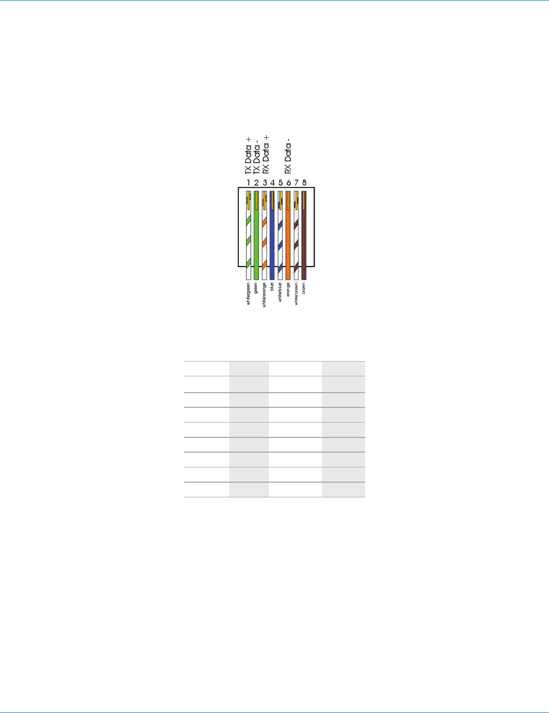
724-746-5500 | blackbox.com
Page 56
724-746-5500 | blackbox.com
Appendix B: Connector Pinouts
NOTES:
1. In the RS-422 mode, TX lines are outputs and RX lines are inputs. Connect the Hardened Serial Server TXB(+) line to the
RXB(+) line of the serial device, and the Hardened Serial Server TXA(-) to the RXA(-) of the serial device.
2. Ground is signal ground and provides a common mode reference for the RS-422 Receiver and Transmitters.
B.3 Standard Ethernet Cable RJ-45 Pinout
Figure B-3. RJ-45 Ethernet cable pinout.
Table B-3. RJ-45 cable pinout.
RJ-45 Pin Signal Wire Color RJ-45 Pin
1TX+ White-Green 1
2TX- Green 2
3RX+ White-Orange 3
4Not used Blue 4
5Not used White-Blue 5
6RX- Orange 6
7Not used White-Brown 7
8Not used Brown 8

724-746-5500 | blackbox.com
724-746-5500 | blackbox.com Page 57
NOTES

724-746-5500 | blackbox.com
Page 58
724-746-5500 | blackbox.com
NOTES

724-746-5500 | blackbox.com
724-746-5500 | blackbox.com Page 59
NOTES

724-746-5500 | blackbox.com
About Black Box
Black Box provides an extensive range of networking and infrastructure products. You’ll find everything from cabinets and racks
and power and surge protection products to media converters and Ethernet switches all supported by free, live 24/7 Tech support
available in 30 seconds or less.
© Copyright 2013. Black Box Corporation. All rights reserved. Black Box® and the Double Diamond logo are registered trademarks of BB Technologies, Inc.
Any third-party trademarks appearing in this manual are acknowledged to be the property of their respective owners.
BLACK BOX®
Black Box Tech Support: FREE! Live. 24/7.
Tech support the
way it should be.
Great tech support is just 30 seconds away at 724-746-5500 or blackbox.com.
LES421A user manual, version 2
