Black Box Compact T1 Mt850A Users Manual
MT850A to the manual 0b776daf-7014-42e1-b522-e3a77ee695aa
2015-02-02
: Black-Box Black-Box-Compact-T1-Mt850A-Users-Manual-482294 black-box-compact-t1-mt850a-users-manual-482294 black-box pdf
Open the PDF directly: View PDF ![]() .
.
Page Count: 592 [warning: Documents this large are best viewed by clicking the View PDF Link!]
- Compact T1 User Manual
- Preface
- Table of Contents
- 1 - Base Platform
- 2 - Physical Installation
- 3 - Electrical Installation and Cabling
- 4 - Configuration
- Setting up a CLI Connection
- System Information
- Basic System Setup
- Initial Setup
- Set Up Security
- Set Up a DS1/T1
- Set Up a DS0/Channel
- Set Up an Analog Port
- Set Up the Router Card
- Establish a Static Channel Connection
- Set Up a ISDN BRI Service
- Set Up the OCU-DP Card
- Set Up a V.35 Port
- Change the IP Address of the DS0 Management Channel
- Upgrade the Controller Software
- Upgrade the Router (IP or CMG) Software
- Quick Configuration Reload
- Setup of DS0 Management Channel
- 5 - CLI Commands
- Command Line Interface Help
- CLI Commands
- aco (Alarm Cut Off)
- add
- add (router) dns proxy
- add (router) remote
- add (router) snmp community
- add (router) snmp trap
- add (router) static dns host
- add (router) uploaduser
- add (router-lan) filter
- add (router-lan) secondary ip address
- add (router-lan) static
- add (router-wan) firewall
- add (router-wan) gre network
- add (router-wan) nat bypass
- add (router-wan) static
- add user
- alarms
- clear
- connect
- delete
- delete (router) dns proxy
- delete (router) remote
- delete (router) snmp community
- delete (router) snmp trap
- delete (router) static dns host
- delete (router) uploaduser
- delete (router-lan) filter
- delete (router-lan) secondary ip address
- delete (router-lan) static
- delete (router-wan) firewall
- delete (router-wan) gre network
- delete (router-wan) nat bypass
- delete (router-wan) static
- delete (router-wan) static ipx network
- delete user
- disconnect
- exit
- install
- load
- log
- ping
- rename (router)
- reset
- restore
- rtrping
- set
- set alarms
- set autoexit
- set (bri)
- set (bri) autoactivate
- set (bri) mode
- set (bri) pmsync
- set clock
- set date
- set (ds0)
- set (ds1)
- set ethernet ip address
- set (fxo)
- set (fxs5G)
- set id
- set ip gateway
- set ipds0
- set local
- set login auth
- set login support
- set ntp
- set (ocudp) baud
- set (ocudp) loopback
- set (ocudp) loopdetect
- set (ocudp) mvec
- set (ocudp) secondary
- set (ocudp) selftest
- set (ocudp) up/down
- set radius
- set (router) autologout
- set (router) cdr
- set (router) compander
- set (router) default
- set (router) dhcp
- set (router) dns
- set (router) enhanced security
- set (router) hookflash
- set (router) lmi
- set (router) lmi poll
- set (router) log
- set (router) login auth
- set (router) login prompt
- set (router) mgcp
- set (router) ntp
- set (router) password
- set (router) ppp auth
- set (router) ppp security
- set (router) priority tos
- set (router) proxy
- set (router) reboot
- set (router) rip
- set (router) snmp
- set (router) stp
- set (router) syslog
- set (router) voip
- set (router-lan) collision
- set (router-lan) filter forward
- set (router-lan) framing
- set (router-lan) gateway
- set (router-lan) ip address
- set (router-lan) ipx network
- set (router-lan) phy
- set (router-lan) rip
- set (router-lan) stp
- set (router-lan) up/down
- set (router-trunk) encapsulation
- set (router-trunk) multilink group
- set (router-trunk) up/down
- set (router-trunk) voice bandwidth limit
- set (router-voice) algorithm preference
- set (router-voice) cpd
- set (router-voice) default
- set (router-voice) down
- set (router-voice) dtmfrelay
- set (router-voice) echo cancellation
- set (router-voice) echo tail
- set (router-voice) endpoint prefix
- set (router-voice) endpoint suffix
- set (router-voice) log start
- set (router-voice) log stop
- set (router-voice) rxgain
- set (router-voice) silence
- set (router-voice) slash
- set (router-voice) tos
- set (router-voice) txgain
- set (router-voice) up
- set (router-wan) dlci
- set (router-wan) gre
- set (router-wan) ip
- set (router-wan) ip address
- set (router-wan) ipx
- set (router-wan) nat
- set (router-wan) other
- set (router-wan) ppp
- set (router-wan) rip
- set (router-wan) stp
- set (router-wan) trunk
- set (router-wan) up/down
- set screen
- set snmp
- set syslog
- set time
- set user
- set (v35)
- set (v54)
- set verification
- show
- show autoexit
- show (bri)
- show clock
- show connect
- show date
- show (ds0)
- show (ds1)
- show ethernet
- show (fxo)
- show (fxs5G)
- show impedance
- show id
- show ip
- show ipds0
- show local
- show login
- show ntp
- show (ocudp)
- show radius
- show (router)
- show (router) dhcp
- show (router) dns
- show (router) dns proxy
- show (router) lmi
- show (router) log
- show (router) mgcp
- show (router) mgcp algorithmname
- show (router) ntp
- show (router) ppp
- show (router) rip
- show (router) snmp
- show (router) stp
- show (router) syslog
- show (router) uploaduser
- show (router) voip
- show (router-lan)
- show (router-lan) collision
- show (router-lan) filter
- show (router-lan) static
- show (router-lan) stp
- show (router-voice)
- show (router-wan)
- show (router-wan) firewall
- show (router-wan) nat bypass
- show (router-wan) ppp
- show (router-wan) static ip address
- show (router-wan) static ip network
- show (router-wan) static ipx network
- show (router-wan) static mac address
- show (router-wan) static nat address
- show (router-wan) stp
- show (router-wan) trunk
- show screen
- show snmp
- show syslog
- show time
- show users
- show (v35)
- show (v54)
- show (wan)
- status
- status (bri)
- status clock
- status (ds0)
- status (ds1)
- status equipment
- status (fxo)
- status (fxs5G)
- status ipds0
- status (ocudp)
- status (ocudp) performance
- status (ocudp) performance history
- status (router)
- status (router) alarms
- status (router) channels
- status (router) dns
- status (router) events
- status (router) ip address table
- status (router) ip network table
- status (router) ipx network table
- status (router) ipx server table
- status (router) log
- status (router) mac address table
- status (router) mgcp
- status (router) performance
- status (router) stp
- status (router-lan)
- status (router-trunk)
- status (router-voice)
- status sessions
- status (v35)
- status (v54)
- store
- telnet
- 6 - T1 Controller Card
- 7 - FXO Voice Card
- 8 - FXS Voice Card
- 9 - ISDN BRI Card
- 10 - OCU-DP Card
- 11 - Power Supply
- 12 - Quad T1 Card
- 13 - Router (IP) Card
- 14 - Router (CMG) Card
- Overview
- Features
- Technical Specifications
- Controller Software Required
- Management
- Voice and Packet Interfaces
- Voice Processing and Mediation
- Connection Types (Media Flows)
- Routing and Policy Management
- Router Performance
- Advanced Capabilities
- TDM-Side Signaling
- Softswitch Call Control and Signaling
- Services Enabled (under Softswitch Control)
- Softswitch/Call Agent Interoperability
- Network Standards
- Power
- Regulatory Approvals
- Physical
- Card Configuration
- Connector Pinout
- Softswitch Interoperability Settings
- LEDs
- 15 - V.35/V.54 Cards
- 16 - Maintenance
- A - SNMP Interface
- B - Diagnostices & Troubleshooting
- Glossary
- Index
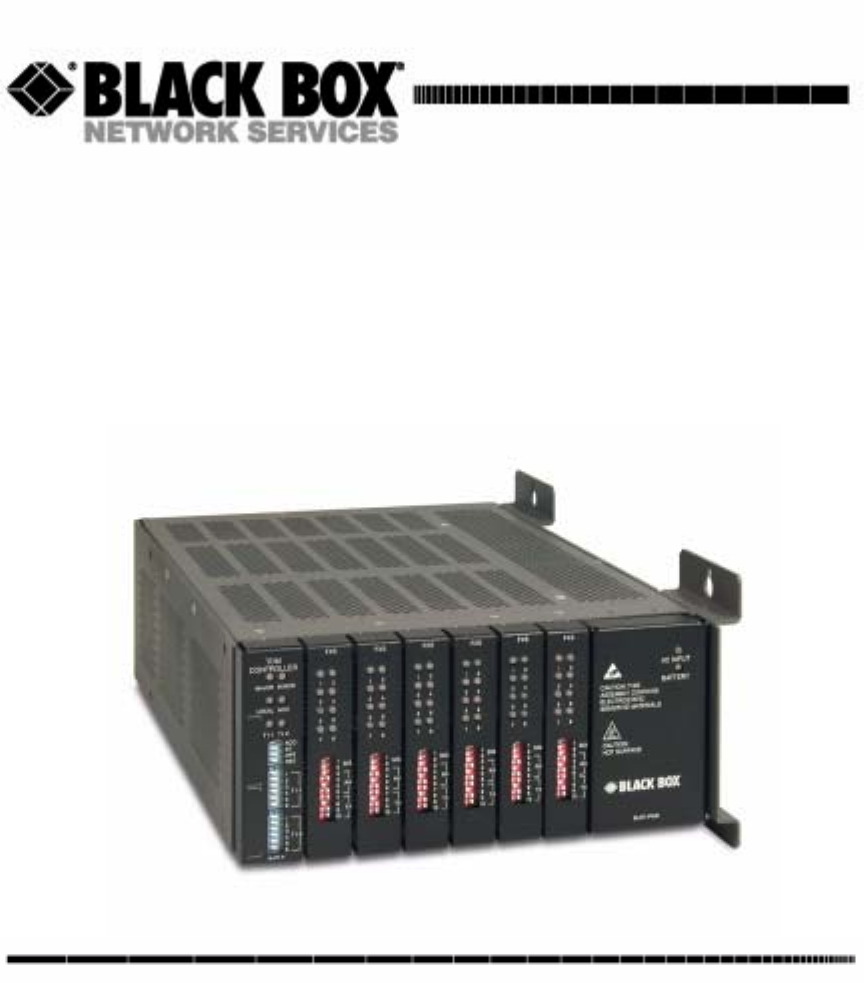
Compact T1
USER MANUAL
CUSTOMER
SUPPORT
INFORMATION
Order toll-free in the U.S.: Call 877-877-BBOX (outside the U.S. call 724-746-5500)
FREE technical support, 24 hours a day, 7 days a week: Call 724-746-5500 or fax 724-746-0746
Mail order: Black Box Corporation, 1000 Park Drive, Lawrence, PA 15055-1018
Web site: www.blackbox.com • E-mail: info@blackbox.com
MAY 2003
PRODUCT P/N MT850A
770-0110-AA

Supporting Software Version:
Controller 6.1
IP Router 1.6
CMG Router 2.0

PREFACE
Preface
Compliance
FCC Requirements for Telephone-Line Equipment
1. The Federal Communications Commission (FCC) has established rules which permit this device
to be directly connected to the telephone network with standardized jacks. This equipment should not
be used on party lines or coin lines.
2. If this device is malfunctioning, it may also be causing harm to the telephone network; this device
should be disconnected until the source of the problem can be determined and until the repair has been
made. If this is not done, the telephone company may temporarily disconnect service.
3. If you have problems with your telephone equipment after installing this device, disconnect this
device from the line to see if it is causing the problem. If it is, contact your supplier or an authorized
agent.
4. The telephone company may make changes in its technical operations and procedures. If any such
changes affect the compatibility or use of this device, the telephone company is required to give
adequate notice of the changes.
5. If the telephone company requests information on what equipment is connected to their lines,
inform them of:
a. The telephone number that this unit is connected to.
b. The ringer equivalence number.
c. The USOC jack required: RJ-11C.
d. The FCC registration number.
Items (b) and (d) can be found on the unit’s FCC label. The ringer equivalence number (REN) is
used to determine how many devices can be connected to your telephone line. In most
areas, the sum of the RENs of all devices on any one line should not exceed five (5.0). If
too many devices are attached, they may not ring properly.
6. In the event of an equipment malfunction, all repairs should be performed by your
supplier or an authorized agent. It is the responsibility of users requiring service to report
the need for service to the supplier or to an authorized agent.

iv Compact T1 - Release 6.1
Preface
Compliance
Certification Notice for Equipment Used in Canada
The Canadian Department of Communications label identifies certified equipment. This
certification means that the equipment meets certain telecommunications-network
protective, operation, and safety requirements. The Department does not guarantee the
equipment will operate to the user’s satisfaction.
Before installing this equipment, users should ensure that it is permissible to be connected to the
facilities of the local telecommunications company. The equipment must also be installed using an
acceptable method of connection. In some cases, the company’s inside wiring associated with a
single-line individual service may be extended by means of a certified connector assembly (extension
cord). The customer should be aware that compliance with the above conditions may not prevent
degradation of service in some situations.
Repairs to certified equipment should be made by an authorized Canadian maintenance facility—in
this case, your supplier. Any repairs or alterations made by the user to this equipment, or equipment
malfunctions, may give the telecommunications company cause to request the user to disconnect the
equipment.
Users should ensure for their own protection that the electrical ground connections of the power
utility, telephone lines, and internal metallic water pipe system, if present, are connected together.
This precaution may be particularly important in rural areas.
CAUTION! USERS SHOULD NOT ATTEMPT TO MAKE SUCH CONNECTIONS
THEMSELVES, BUT SHOULD CONTACT THE APPROPRIATE ELECTRIC INSPECTION
AUTHORITY, OR ELECTRICIAN, AS APPROPRIATE.
The LOAD NUMBER (LN) assigned to each terminal device denotes the percentage of the total load
to be connected to a telephone loop which is used by the device, to prevent overloading. The
termination on a loop may consist of any combination of devices, subject only to the requirement that
the total of the load numbers of all the devices does not exceed 100.

Compact T1 - Release 6.1 v
Preface
Compliance
Federal Communications Commission and Canadian
Department of Communications Radio Frequency
Interference Statements
This equipment generates, uses, and can radiate radio frequency energy and if not installed and used
properly, that is, in strict accordance with the manufacturer’s instructions, may cause interference to
radio communication. It has been tested and found to comply with the limits for a Class A computing
device in accordance with the specifications in Subpart B of Part 15 of FCC rules, which are designed
to provide reasonable protection against such interference when the equipment is operated in a
commercial environment. Operation of this equipment in a residential area is likely to cause
interference, in which case the user at his own expense will be required to take whatever measures
may be necessary to correct the interference.
Changes or modifications not expressly approved by the party responsible for compliance could void
the user’s authority to operate the equipment.
This digital apparatus does not exceed the Class A limits for radio noise emission from digital
apparatus set out in the Radio Interference Regulation of the Canadian Department of
Communications.
Le présent appareil numérique n’émet pas de bruits radioélectriques dépassant les limites
applicables aux appareils numériques de la classe A prescrites dans le Règlement sur le brouillage
radioélectrique publié par le ministère des Communications du Canada.

vi Compact T1 - Release 6.1
Preface
Compliance
Normas Oficiales Mexicanas (NOM) Electrical Safety
Statement Instrucciones de Seguridad
1. Todas las instrucciones de seguridad y operación deberán ser leídas antes de que el aparato
eléctrico sea operado.
2. Las instrucciones de seguridad y operación deberán ser guardadas para referencia futura.
3. Todas las advertencias en el aparato eléctrico y en sus instrucciones de operación deben ser
respetadas.
4. Todas las instrucciones de operación y uso deben ser seguidas.
5. El aparato eléctrico no deberá ser usado cerca del agua—por ejemplo, cerca de la tina de baño,
lavabo, sótano mojado o cerca de una alberca, etc.
6. El aparato eléctrico debe ser usado únicamente con carritos o pedestales que sean recomendados
por el fabricante.
7. El aparato eléctrico debe ser montado a la pared o al techo sólo como sea recomendado por el
fabricante.
8. Servicio—El usuario no debe intentar dar servicio al equipo eléctrico más allá a lo descrito en las
instrucciones de operación. Todo otro servicio deberá ser referido a personal de servicio calificado.
9. El aparato eléctrico debe ser situado de tal manera que su posición no interfiera su uso. La
colocación del aparato eléctrico sobre una cama, sofá, alfombra o superficie similar puede bloquea la
ventilación, no se debe colocar en libreros o gabinetes que impidan el flujo de aire por los orificios
de ventilación.
10. El equipo eléctrico deber ser situado fuera del alcance de fuentes de calor como radiadores,
registros de calor, estufas u otros aparatos (incluyendo amplificadores) que producen calor.
11. El aparato eléctrico deberá ser connectado a una fuente de poder sólo del tipo descrito en el
instructivo de operación, o como se indique en el aparato.
12. Precaución debe ser tomada de tal manera que la tierra fisica y la polarización del equipo no sea
eliminada.
13. Los cables de la fuente de poder deben ser guiados de tal manera que no sean pisados ni
pellizcados por objetos colocados sobre o contra ellos, poniendo particular atención a los contactos y
receptáculos donde salen del aparato.
14. El equipo eléctrico debe ser limpiado únicamente de acuerdo a las recomendaciones del
fabricante.
15. En caso de existir, una antena externa deberá ser localizada lejos de las lineas de energia.

Compact T1 - Release 6.1 vii
Preface
Compliance
16. El cable de corriente deberá ser desconectado del cuando el equipo no sea usado por un largo
periodo de tiempo.
17. Cuidado debe ser tomado de tal manera que objectos liquidos no sean derramados sobre la
cubierta u orificios de ventilación.
18. Servicio por personal calificado deberá ser provisto cuando:
A: El cable de poder o el contacto ha sido dañado; u
B: Objectos han caído o líquido ha sido derramado dentro del aparato; o
C: El aparato ha sido expuesto a la lluvia; o
D: El aparato parece no operar normalmente o muestra un cambio en su desempeño; o
E: El aparato ha sido tirado o su cubierta ha sido dañada.

viii Compact T1 - Release 6.1
Preface
Safety Information
Safety Information
CAUTION! ALWAYS USE CAUTION WHEN INSTALLING TELEPHONE LINES.
READ THE CAUTIONS BELOW FOR DETAILS ON SAFETY GUIDELINES TO PREVENT
INJURY.
lNever touch uninsulated telephone wires and terminals unless the
telephone line has been disconnected at the Network Interface (NI) as
voltage potentials as high as 300 VAC may be present across the transmit
and receive pairs
lOnly use No. 26 AWG or larger telecommunication line cord, to reduce
the risk of fire
lNever install telephone wiring during a lightning storm
lNever install telephone jacks in wet locations unless the jack is
specifically designed for wet locations
lRefer to the installation section of this manual for a safe and proper
installation procedure. All wiring external to this equipment should follow
the current provision of the National Electrical Code

Compact T1 - Release 6.1 ix
Preface
Notices
Notices
This manual contains important information and warnings that must be followed to
ensure safe operation of the equipment.
DANGER! A DANGER NOTICE INDICATES THE PRESENCE OF A HAZARD THAT
CAN OR WILL CAUSE DEATH OR SEVERE PERSONAL INJURY IF THE HAZARD IS
NOT AVOIDED.
CAUTION! A CAUTION NOTICE INDICATES THE POSSIBILITY OF
INTERRUPTING NETWORK SERVICE IF THE HAZARD IS NOT AVOIDED.
WARNING! A WARNING NOTICE INDICATES THE POSSIBILITY OF EQUIPMENT
DAMAGE IF THE HAZARD IS NOT AVOIDED.
NOTE: A Note indicates information to help you understand how to
perform a procedure or how the system works. Notes should be read before
performing the required action.

x Compact T1 - Release 6.1
Preface
Electrostatic Discharge (ESD) Precautions
Electrostatic Discharge (ESD) Precautions
ESD can damage processors, circuit cards, and other electronic components. Always
observe the following precautions before installing a system component.
1. Do not remove a component from its protective packaging until ready to
install.
2. Wear a wrist grounding strap and attach it to a metal part of the system unit
before handling components. If a wrist strap is not available, maintain contact
with the system unit throughout any procedure requiring ESD protection.
WARNING! INTEGRATED CIRCUITS (ICS) ARE EXTREMELY SUSCEPTIBLE TO
ELECTROSTATIC DISCHARGE. UNLESS YOU ARE A QUALIFIED SERVICE TECHNICIAN WHO
USES TOOLS AND TECHNIQUES THAT CONFORM TO ACCEPTED INDUSTRY PRACTICES, DO
NOT HANDLE ICS.
The ESD warning label appears on packages and storage bags
that contain static-sensitive products and components.

TABLE OF CONTENTS
Preface
Compliance . . . . . . . . . . . . . . . . . . . . . . . . . . . . . . . . . . . . . . . . . . . . . . . . . iii
FCC Requirements for Telephone-Line Equipment . . . . . . . . . . . . . . iii
Certification Notice for Equipment Used in Canada . . . . . . . . . . . . . iv
Federal Communications Commission and Canadian Department of
Communications Radio Frequency Interference Statements . . . . . v
Normas Oficiales Mexicanas (NOM) Electrical Safety Statement
Instrucciones de Seguridad . . . . . . . . . . . . . . . . . . . . . . . . . . . . . vi
Safety Information . . . . . . . . . . . . . . . . . . . . . . . . . . . . . . . . . . . . . . . . . . viii
Notices . . . . . . . . . . . . . . . . . . . . . . . . . . . . . . . . . . . . . . . . . . . . . . . . . . . . ix
Electrostatic Discharge (ESD) Precautions . . . . . . . . . . . . . . . . . . . . . . . . . x
1Base Platform
Overview. . . . . . . . . . . . . . . . . . . . . . . . . . . . . . . . . . . . . . . . . . . . . . . . . . 1-2
Features . . . . . . . . . . . . . . . . . . . . . . . . . . . . . . . . . . . . . . . . . . . . . . . . . . . 1-3
Dual T1 Controller . . . . . . . . . . . . . . . . . . . . . . . . . . . . . . . . . . . . . . . . . . 1-3
Power Supply . . . . . . . . . . . . . . . . . . . . . . . . . . . . . . . . . . . . . . . . . . . . . . 1-3
115 VAC/-48 VDC Power Supply/Charger. . . . . . . . . . . . . . . . . . . . 1-3
Service Cards. . . . . . . . . . . . . . . . . . . . . . . . . . . . . . . . . . . . . . . . . . . . . . . 1-4
FXS Service card . . . . . . . . . . . . . . . . . . . . . . . . . . . . . . . . . . . . . . . . 1-4
FXO Service card. . . . . . . . . . . . . . . . . . . . . . . . . . . . . . . . . . . . . . . . 1-4
ISDN BRI Service card . . . . . . . . . . . . . . . . . . . . . . . . . . . . . . . . . . . 1-4
OCU-DP Service card . . . . . . . . . . . . . . . . . . . . . . . . . . . . . . . . . . . . 1-4
Quad T1 Service card. . . . . . . . . . . . . . . . . . . . . . . . . . . . . . . . . . . . . 1-4
V.35 and V.35/54 Service cards. . . . . . . . . . . . . . . . . . . . . . . . . . . . . 1-5
IP Router Service card . . . . . . . . . . . . . . . . . . . . . . . . . . . . . . . . . . . . 1-5
CMG Router Service card . . . . . . . . . . . . . . . . . . . . . . . . . . . . . . . . . 1-5
Local and Remote Management . . . . . . . . . . . . . . . . . . . . . . . . . . . . . . . . 1-6
Technical Specifications . . . . . . . . . . . . . . . . . . . . . . . . . . . . . . . . . . . . . . 1-6
Platform Features. . . . . . . . . . . . . . . . . . . . . . . . . . . . . . . . . . . . . . . . 1-6
Basic System . . . . . . . . . . . . . . . . . . . . . . . . . . . . . . . . . . . . . . . . . . . 1-6
Table of Contents

xii Compact T1 - Release 6.1
Table of Contents
Management . . . . . . . . . . . . . . . . . . . . . . . . . . . . . . . . . . . . . . . . . . . .1-7
Management Ports. . . . . . . . . . . . . . . . . . . . . . . . . . . . . . . . . . . . . . . .1-7
Network Interface . . . . . . . . . . . . . . . . . . . . . . . . . . . . . . . . . . . . . . . .1-7
Network Standards . . . . . . . . . . . . . . . . . . . . . . . . . . . . . . . . . . . . . . .1-7
Clocking . . . . . . . . . . . . . . . . . . . . . . . . . . . . . . . . . . . . . . . . . . . . . . .1-7
Alarms. . . . . . . . . . . . . . . . . . . . . . . . . . . . . . . . . . . . . . . . . . . . . . . . . 1-7
Testing and Diagnostics . . . . . . . . . . . . . . . . . . . . . . . . . . . . . . . . . . .1-7
Power. . . . . . . . . . . . . . . . . . . . . . . . . . . . . . . . . . . . . . . . . . . . . . . . . .1-8
Rear Chassis Interfaces . . . . . . . . . . . . . . . . . . . . . . . . . . . . . . . . . . . .1-8
Regulatory Approvals . . . . . . . . . . . . . . . . . . . . . . . . . . . . . . . . . . . . .1-9
Physical Information . . . . . . . . . . . . . . . . . . . . . . . . . . . . . . . . . . . . . . 1-9
Chassis . . . . . . . . . . . . . . . . . . . . . . . . . . . . . . . . . . . . . . . . . . . . . . . . . . . 1-10
RS-232 Craft Port (Female DB-9) . . . . . . . . . . . . . . . . . . . . . . . . . .1-11
T1 and 10Base-T Ethernet . . . . . . . . . . . . . . . . . . . . . . . . . . . . . . . .1-12
2Physical Installation
Unpacking and Inspection . . . . . . . . . . . . . . . . . . . . . . . . . . . . . . . . . . . . .2-2
Installation Environment . . . . . . . . . . . . . . . . . . . . . . . . . . . . . . . . . . . . . .2-2
Assembly of Unit . . . . . . . . . . . . . . . . . . . . . . . . . . . . . . . . . . . . . . . . . . . . 2-3
Wall Mounting . . . . . . . . . . . . . . . . . . . . . . . . . . . . . . . . . . . . . . . . . . . . . .2-4
Rack Mounting (Optional Feature) . . . . . . . . . . . . . . . . . . . . . . . . . . . . . . 2-5
3Electrical Installation and Cabling
Compliant Installation . . . . . . . . . . . . . . . . . . . . . . . . . . . . . . . . . . . . . . . . 3-2
Ferrite Beads . . . . . . . . . . . . . . . . . . . . . . . . . . . . . . . . . . . . . . . . . . . .3-3
Chassis Connectors and Buttons . . . . . . . . . . . . . . . . . . . . . . . . . . . . . . . . 3-4
Interface Connectors. . . . . . . . . . . . . . . . . . . . . . . . . . . . . . . . . . . . . . . . . .3-4
Chassis Ground Connector . . . . . . . . . . . . . . . . . . . . . . . . . . . . . . . . . 3-5
Power Reset. . . . . . . . . . . . . . . . . . . . . . . . . . . . . . . . . . . . . . . . . . . . .3-6
Power Connections . . . . . . . . . . . . . . . . . . . . . . . . . . . . . . . . . . . . . . .3-6
External Alarm Connector . . . . . . . . . . . . . . . . . . . . . . . . . . . . . . . . . 3-8
25-Pair Telco Connectors . . . . . . . . . . . . . . . . . . . . . . . . . . . . . . . . . .3-9
RS-232 Craft Port (Female DB-9) . . . . . . . . . . . . . . . . . . . . . . . . . .3-11
T1 Connection Ports . . . . . . . . . . . . . . . . . . . . . . . . . . . . . . . . . . . . .3-12
10Base-T Ethernet . . . . . . . . . . . . . . . . . . . . . . . . . . . . . . . . . . . . . . 3-12

Compact T1 - Release 6.1 xiii
Table of Contents
4Configuration
Setting up a CLI Connection. . . . . . . . . . . . . . . . . . . . . . . . . . . . . . . . . . . 4-2
System Information. . . . . . . . . . . . . . . . . . . . . . . . . . . . . . . . . . . . . . . . . . 4-3
Basic System Setup. . . . . . . . . . . . . . . . . . . . . . . . . . . . . . . . . . . . . . . . . . 4-4
Initial Setup . . . . . . . . . . . . . . . . . . . . . . . . . . . . . . . . . . . . . . . . . . . . 4-4
Set Up Security . . . . . . . . . . . . . . . . . . . . . . . . . . . . . . . . . . . . . . . . . 4-5
Set Up a DS1/T1 . . . . . . . . . . . . . . . . . . . . . . . . . . . . . . . . . . . . . . . . 4-5
Set Up a DS0/Channel . . . . . . . . . . . . . . . . . . . . . . . . . . . . . . . . . . . . 4-6
Set Up an Analog Port . . . . . . . . . . . . . . . . . . . . . . . . . . . . . . . . . . . . 4-6
Set Up the Router Card . . . . . . . . . . . . . . . . . . . . . . . . . . . . . . . . . . . 4-7
Establish a Static Channel Connection . . . . . . . . . . . . . . . . . . . . . . . 4-8
Set Up a ISDN BRI Service. . . . . . . . . . . . . . . . . . . . . . . . . . . . . . . . 4-8
Set Up the OCU-DP Card . . . . . . . . . . . . . . . . . . . . . . . . . . . . . . . . . 4-9
Set Up a V.35 Port . . . . . . . . . . . . . . . . . . . . . . . . . . . . . . . . . . . . . . 4-10
Change the IP Address of the DS0 Management Channel . . . . . . . 4-10
Upgrade the Controller Software. . . . . . . . . . . . . . . . . . . . . . . . . . . 4-11
Upgrade the Router (IP or CMG) Software. . . . . . . . . . . . . . . . . . . 4-11
Quick Configuration Reload . . . . . . . . . . . . . . . . . . . . . . . . . . . . . . . . . . 4-12
Setup of DS0 Management Channel . . . . . . . . . . . . . . . . . . . . . . . . . . . . 4-15
Equipment Required . . . . . . . . . . . . . . . . . . . . . . . . . . . . . . . . . . . . 4-16
Application Overview . . . . . . . . . . . . . . . . . . . . . . . . . . . . . . . . . . . 4-16
Operation . . . . . . . . . . . . . . . . . . . . . . . . . . . . . . . . . . . . . . . . . . . . . 4-16
Provision DS0s for data and cross-connect to the outgoing T1. . . . 4-17
Configure the Router . . . . . . . . . . . . . . . . . . . . . . . . . . . . . . . . . . . . 4-17
Setup the Profile for Site A . . . . . . . . . . . . . . . . . . . . . . . . . . . . . . . 4-18
Setup the Profile for Site B . . . . . . . . . . . . . . . . . . . . . . . . . . . . . . . 4-18
Setup the Profile for Site C . . . . . . . . . . . . . . . . . . . . . . . . . . . . . . . 4-19
Remote Site A Configuration. . . . . . . . . . . . . . . . . . . . . . . . . . . . . . 4-19
Remote Site B Configuration. . . . . . . . . . . . . . . . . . . . . . . . . . . . . . 4-20
Remote Site C Configuration. . . . . . . . . . . . . . . . . . . . . . . . . . . . . . 4-21
Test. . . . . . . . . . . . . . . . . . . . . . . . . . . . . . . . . . . . . . . . . . . . . . . . . . 4-21

xiv Compact T1 - Release 6.1
Table of Contents
5CLI Commands
Command Line Interface Help. . . . . . . . . . . . . . . . . . . . . . . . . . . . . . . . . .5-2
? or help. . . . . . . . . . . . . . . . . . . . . . . . . . . . . . . . . . . . . . . . . . . . . . . .5-2
[TAB] usage for word or command completion. . . . . . . . . . . . . . . . .5-2
CLI Commands . . . . . . . . . . . . . . . . . . . . . . . . . . . . . . . . . . . . . . . . . . . . .5-4
aco (Alarm Cut Off) . . . . . . . . . . . . . . . . . . . . . . . . . . . . . . . . . . . . . . . . .5-5
add . . . . . . . . . . . . . . . . . . . . . . . . . . . . . . . . . . . . . . . . . . . . . . . . . . . . . . .5-6
add (router) dns proxy. . . . . . . . . . . . . . . . . . . . . . . . . . . . . . . . . . . . .5-7
add (router) remote . . . . . . . . . . . . . . . . . . . . . . . . . . . . . . . . . . . . . . . 5-7
add (router) snmp community. . . . . . . . . . . . . . . . . . . . . . . . . . . . . . .5-8
add (router) snmp trap. . . . . . . . . . . . . . . . . . . . . . . . . . . . . . . . . . . . .5-9
add (router) static dns host . . . . . . . . . . . . . . . . . . . . . . . . . . . . . . . .5-10
add (router) uploaduser . . . . . . . . . . . . . . . . . . . . . . . . . . . . . . . . . . .5-11
add (router-lan) filter. . . . . . . . . . . . . . . . . . . . . . . . . . . . . . . . . . . . .5-12
add (router-lan) secondary ip address . . . . . . . . . . . . . . . . . . . . . . . .5-15
add (router-lan) static . . . . . . . . . . . . . . . . . . . . . . . . . . . . . . . . . . . .5-16
add (router-wan) firewall . . . . . . . . . . . . . . . . . . . . . . . . . . . . . . . . .5-20
add (router-wan) gre network . . . . . . . . . . . . . . . . . . . . . . . . . . . . . .5-23
add (router-wan) nat bypass . . . . . . . . . . . . . . . . . . . . . . . . . . . . . . .5-24
add (router-wan) static . . . . . . . . . . . . . . . . . . . . . . . . . . . . . . . . . . .5-25
add user . . . . . . . . . . . . . . . . . . . . . . . . . . . . . . . . . . . . . . . . . . . . . . .5-29
alarms . . . . . . . . . . . . . . . . . . . . . . . . . . . . . . . . . . . . . . . . . . . . . . . . . . . 5-30
clear . . . . . . . . . . . . . . . . . . . . . . . . . . . . . . . . . . . . . . . . . . . . . . . . . . . . .5-31
clear (ds1) . . . . . . . . . . . . . . . . . . . . . . . . . . . . . . . . . . . . . . . . . . . . .5-32
clear log. . . . . . . . . . . . . . . . . . . . . . . . . . . . . . . . . . . . . . . . . . . . . . .5-32
clear (router) ip address table . . . . . . . . . . . . . . . . . . . . . . . . . . . . . .5-33
clear (router) log . . . . . . . . . . . . . . . . . . . . . . . . . . . . . . . . . . . . . . . .5-33
clear (router) mac address table . . . . . . . . . . . . . . . . . . . . . . . . . . . .5-34
clear (router) mgcp stats . . . . . . . . . . . . . . . . . . . . . . . . . . . . . . . . . .5-34
clear (router) performance. . . . . . . . . . . . . . . . . . . . . . . . . . . . . . . . .5-35
connect . . . . . . . . . . . . . . . . . . . . . . . . . . . . . . . . . . . . . . . . . . . . . . . . . . .5-36
connect (bri) [4:1 mode] . . . . . . . . . . . . . . . . . . . . . . . . . . . . . . . . . . 5-36
Channel Associated Signaling (CAS) Conversions . . . . . . . . . . . . .5-37
connect (router-trunk) (t1). . . . . . . . . . . . . . . . . . . . . . . . . . . . . . . . . 5-38

Compact T1 - Release 6.1 xv
Table of Contents
connect (card-trunk) (card-trunk). . . . . . . . . . . . . . . . . . . . . . . . . . . 5-39
connect (router-voice) (t1|fxs) . . . . . . . . . . . . . . . . . . . . . . . . . . . . . 5-40
delete . . . . . . . . . . . . . . . . . . . . . . . . . . . . . . . . . . . . . . . . . . . . . . . . . . . 5-41
delete (router) dns proxy . . . . . . . . . . . . . . . . . . . . . . . . . . . . . . . . . 5-42
delete (router) remote. . . . . . . . . . . . . . . . . . . . . . . . . . . . . . . . . . . . 5-42
delete (router) snmp community . . . . . . . . . . . . . . . . . . . . . . . . . . . 5-43
delete (router) snmp trap . . . . . . . . . . . . . . . . . . . . . . . . . . . . . . . . . 5-43
delete (router) static dns host . . . . . . . . . . . . . . . . . . . . . . . . . . . . . . 5-44
delete (router) uploaduser . . . . . . . . . . . . . . . . . . . . . . . . . . . . . . . . 5-44
delete (router-lan) filter . . . . . . . . . . . . . . . . . . . . . . . . . . . . . . . . . . 5-45
delete (router-lan) secondary ip address . . . . . . . . . . . . . . . . . . . . . 5-46
delete (router-lan) static . . . . . . . . . . . . . . . . . . . . . . . . . . . . . . . . . . 5-47
delete (router-wan) firewall . . . . . . . . . . . . . . . . . . . . . . . . . . . . . . . 5-50
delete (router-wan) gre network. . . . . . . . . . . . . . . . . . . . . . . . . . . . 5-51
delete (router-wan) nat bypass. . . . . . . . . . . . . . . . . . . . . . . . . . . . . 5-52
delete (router-wan) static . . . . . . . . . . . . . . . . . . . . . . . . . . . . . . . . . 5-53
delete (router-wan) static ipx network . . . . . . . . . . . . . . . . . . . . . . . 5-54
delete user . . . . . . . . . . . . . . . . . . . . . . . . . . . . . . . . . . . . . . . . . . . . 5-56
disconnect . . . . . . . . . . . . . . . . . . . . . . . . . . . . . . . . . . . . . . . . . . . . . . . . 5-57
disconnect. . . . . . . . . . . . . . . . . . . . . . . . . . . . . . . . . . . . . . . . . . . . . 5-57
exit . . . . . . . . . . . . . . . . . . . . . . . . . . . . . . . . . . . . . . . . . . . . . . . . . . . . . 5-57
install . . . . . . . . . . . . . . . . . . . . . . . . . . . . . . . . . . . . . . . . . . . . . . . . . . . 5-58
install (slot) router . . . . . . . . . . . . . . . . . . . . . . . . . . . . . . . . . . . . . . 5-58
load . . . . . . . . . . . . . . . . . . . . . . . . . . . . . . . . . . . . . . . . . . . . . . . . . . . . . 5-59
load tftp . . . . . . . . . . . . . . . . . . . . . . . . . . . . . . . . . . . . . . . . . . . . . . 5-59
load xmodem . . . . . . . . . . . . . . . . . . . . . . . . . . . . . . . . . . . . . . . . . . 5-60
log . . . . . . . . . . . . . . . . . . . . . . . . . . . . . . . . . . . . . . . . . . . . . . . . . . . . . . 5-61
ping . . . . . . . . . . . . . . . . . . . . . . . . . . . . . . . . . . . . . . . . . . . . . . . . . . . . . 5-62
print . . . . . . . . . . . . . . . . . . . . . . . . . . . . . . . . . . . . . . . . . . . . . . . . . . . . 5-63
print config. . . . . . . . . . . . . . . . . . . . . . . . . . . . . . . . . . . . . . . . . . . . 5-63
print help . . . . . . . . . . . . . . . . . . . . . . . . . . . . . . . . . . . . . . . . . . . . . 5-64
rename (router) . . . . . . . . . . . . . . . . . . . . . . . . . . . . . . . . . . . . . . . . . . . . 5-64
reset . . . . . . . . . . . . . . . . . . . . . . . . . . . . . . . . . . . . . . . . . . . . . . . . . . . . 5-65
reset . . . . . . . . . . . . . . . . . . . . . . . . . . . . . . . . . . . . . . . . . . . . . . . . . 5-65

xvi Compact T1 - Release 6.1
Table of Contents
reset (router) . . . . . . . . . . . . . . . . . . . . . . . . . . . . . . . . . . . . . . . . . . . 5-65
restore . . . . . . . . . . . . . . . . . . . . . . . . . . . . . . . . . . . . . . . . . . . . . . . . . . .5-66
restore defaults . . . . . . . . . . . . . . . . . . . . . . . . . . . . . . . . . . . . . . . . .5-66
rtrping . . . . . . . . . . . . . . . . . . . . . . . . . . . . . . . . . . . . . . . . . . . . . . . . . . .5-67
set . . . . . . . . . . . . . . . . . . . . . . . . . . . . . . . . . . . . . . . . . . . . . . . . . . . . . . .5-68
set alarms. . . . . . . . . . . . . . . . . . . . . . . . . . . . . . . . . . . . . . . . . . . . . .5-70
set autoexit. . . . . . . . . . . . . . . . . . . . . . . . . . . . . . . . . . . . . . . . . . . . .5-70
set (bri) . . . . . . . . . . . . . . . . . . . . . . . . . . . . . . . . . . . . . . . . . . . . . . .5-71
set (bri) autoactivate . . . . . . . . . . . . . . . . . . . . . . . . . . . . . . . . . . . . . 5-72
set (bri) mode . . . . . . . . . . . . . . . . . . . . . . . . . . . . . . . . . . . . . . . . . .5-72
set (bri) pmsync. . . . . . . . . . . . . . . . . . . . . . . . . . . . . . . . . . . . . . . . .5-73
set clock. . . . . . . . . . . . . . . . . . . . . . . . . . . . . . . . . . . . . . . . . . . . . . . 5-74
set date. . . . . . . . . . . . . . . . . . . . . . . . . . . . . . . . . . . . . . . . . . . . . . . .5-74
set (ds0) . . . . . . . . . . . . . . . . . . . . . . . . . . . . . . . . . . . . . . . . . . . . . . .5-75
set (ds1) . . . . . . . . . . . . . . . . . . . . . . . . . . . . . . . . . . . . . . . . . . . . . . .5-76
set ethernet ip address . . . . . . . . . . . . . . . . . . . . . . . . . . . . . . . . . . . .5-79
set (fxo) . . . . . . . . . . . . . . . . . . . . . . . . . . . . . . . . . . . . . . . . . . . . . . .5-79
set (fxs5G). . . . . . . . . . . . . . . . . . . . . . . . . . . . . . . . . . . . . . . . . . . . .5-80
set id . . . . . . . . . . . . . . . . . . . . . . . . . . . . . . . . . . . . . . . . . . . . . . . . .5-81
set ip gateway . . . . . . . . . . . . . . . . . . . . . . . . . . . . . . . . . . . . . . . . . .5-81
set ipds0. . . . . . . . . . . . . . . . . . . . . . . . . . . . . . . . . . . . . . . . . . . . . . .5-82
set local . . . . . . . . . . . . . . . . . . . . . . . . . . . . . . . . . . . . . . . . . . . . . . .5-83
set login auth . . . . . . . . . . . . . . . . . . . . . . . . . . . . . . . . . . . . . . . . . . .5-83
set login support . . . . . . . . . . . . . . . . . . . . . . . . . . . . . . . . . . . . . . . . 5-83
set ntp . . . . . . . . . . . . . . . . . . . . . . . . . . . . . . . . . . . . . . . . . . . . . . . .5-84
set (ocudp) baud . . . . . . . . . . . . . . . . . . . . . . . . . . . . . . . . . . . . . . . . 5-86
set (ocudp) loopback . . . . . . . . . . . . . . . . . . . . . . . . . . . . . . . . . . . . .5-87
set (ocudp) loopdetect . . . . . . . . . . . . . . . . . . . . . . . . . . . . . . . . . . . .5-88
set (ocudp) mvec . . . . . . . . . . . . . . . . . . . . . . . . . . . . . . . . . . . . . . . . 5-89
set (ocudp) secondary . . . . . . . . . . . . . . . . . . . . . . . . . . . . . . . . . . . .5-89
set (ocudp) selftest. . . . . . . . . . . . . . . . . . . . . . . . . . . . . . . . . . . . . . . 5-90
set (ocudp) up/down . . . . . . . . . . . . . . . . . . . . . . . . . . . . . . . . . . . . .5-90
set radius . . . . . . . . . . . . . . . . . . . . . . . . . . . . . . . . . . . . . . . . . . . . . .5-91

Compact T1 - Release 6.1 xvii
Table of Contents
set (router) autologout . . . . . . . . . . . . . . . . . . . . . . . . . . . . . . . . . . . 5-93
set (router) cdr . . . . . . . . . . . . . . . . . . . . . . . . . . . . . . . . . . . . . . . . . 5-94
set (router) compander . . . . . . . . . . . . . . . . . . . . . . . . . . . . . . . . . . . 5-94
set (router) default . . . . . . . . . . . . . . . . . . . . . . . . . . . . . . . . . . . . . . 5-95
set (router) dhcp . . . . . . . . . . . . . . . . . . . . . . . . . . . . . . . . . . . . . . . . 5-96
set (router) dns . . . . . . . . . . . . . . . . . . . . . . . . . . . . . . . . . . . . . . . . 5-101
set (router) enhanced security . . . . . . . . . . . . . . . . . . . . . . . . . . . . 5-103
set (router) hookflash . . . . . . . . . . . . . . . . . . . . . . . . . . . . . . . . . . . 5-103
set (router) lmi . . . . . . . . . . . . . . . . . . . . . . . . . . . . . . . . . . . . . . . . 5-104
set (router) lmi poll . . . . . . . . . . . . . . . . . . . . . . . . . . . . . . . . . . . . 5-104
set (router) log . . . . . . . . . . . . . . . . . . . . . . . . . . . . . . . . . . . . . . . . 5-105
set (router) login auth. . . . . . . . . . . . . . . . . . . . . . . . . . . . . . . . . . . 5-106
set (router) login prompt . . . . . . . . . . . . . . . . . . . . . . . . . . . . . . . . 5-107
set (router) mgcp . . . . . . . . . . . . . . . . . . . . . . . . . . . . . . . . . . . . . . 5-108
set (router) ntp . . . . . . . . . . . . . . . . . . . . . . . . . . . . . . . . . . . . . . . . 5-127
set (router) password . . . . . . . . . . . . . . . . . . . . . . . . . . . . . . . . . . . 5-129
set (router) ppp auth. . . . . . . . . . . . . . . . . . . . . . . . . . . . . . . . . . . . 5-130
set (router) ppp security . . . . . . . . . . . . . . . . . . . . . . . . . . . . . . . . . 5-132
set (router) priority tos . . . . . . . . . . . . . . . . . . . . . . . . . . . . . . . . . . 5-134
set (router) proxy . . . . . . . . . . . . . . . . . . . . . . . . . . . . . . . . . . . . . . 5-135
set (router) reboot. . . . . . . . . . . . . . . . . . . . . . . . . . . . . . . . . . . . . . 5-136
set (router) rip. . . . . . . . . . . . . . . . . . . . . . . . . . . . . . . . . . . . . . . . . 5-136
set (router) snmp . . . . . . . . . . . . . . . . . . . . . . . . . . . . . . . . . . . . . . 5-137
set (router) stp . . . . . . . . . . . . . . . . . . . . . . . . . . . . . . . . . . . . . . . . 5-139
set (router) syslog. . . . . . . . . . . . . . . . . . . . . . . . . . . . . . . . . . . . . . 5-142
set (router) voip . . . . . . . . . . . . . . . . . . . . . . . . . . . . . . . . . . . . . . . 5-144
set (router-lan) collision. . . . . . . . . . . . . . . . . . . . . . . . . . . . . . . . . 5-153
set (router-lan) filter forward . . . . . . . . . . . . . . . . . . . . . . . . . . . . . 5-155
set (router-lan) framing . . . . . . . . . . . . . . . . . . . . . . . . . . . . . . . . . 5-156
set (router-lan) gateway . . . . . . . . . . . . . . . . . . . . . . . . . . . . . . . . . 5-157
set (router-lan) ip address. . . . . . . . . . . . . . . . . . . . . . . . . . . . . . . . 5-158
set (router-lan) ipx network . . . . . . . . . . . . . . . . . . . . . . . . . . . . . . 5-159
set (router-lan) phy. . . . . . . . . . . . . . . . . . . . . . . . . . . . . . . . . . . . . 5-160

xviii Compact T1 - Release 6.1
Table of Contents
set (router-lan) rip . . . . . . . . . . . . . . . . . . . . . . . . . . . . . . . . . . . . . . 5-161
set (router-lan) stp . . . . . . . . . . . . . . . . . . . . . . . . . . . . . . . . . . . . . . 5-163
set (router-lan) up/down . . . . . . . . . . . . . . . . . . . . . . . . . . . . . . . . . 5-165
set (router-trunk) encapsulation . . . . . . . . . . . . . . . . . . . . . . . . . . . 5-166
set (router-trunk) multilink group . . . . . . . . . . . . . . . . . . . . . . . . . .5-166
set (router-trunk) up/down . . . . . . . . . . . . . . . . . . . . . . . . . . . . . . .5-167
set (router-trunk) voice bandwidth limit . . . . . . . . . . . . . . . . . . . . .5-168
set (router-voice) algorithm preference. . . . . . . . . . . . . . . . . . . . . . 5-169
set (router-voice) cpd . . . . . . . . . . . . . . . . . . . . . . . . . . . . . . . . . . . 5-170
set (router-voice) default. . . . . . . . . . . . . . . . . . . . . . . . . . . . . . . . .5-171
set (router-voice) down . . . . . . . . . . . . . . . . . . . . . . . . . . . . . . . . . .5-172
set (router-voice) dtmfrelay. . . . . . . . . . . . . . . . . . . . . . . . . . . . . . .5-173
set (router-voice) echo cancellation . . . . . . . . . . . . . . . . . . . . . . . .5-173
set (router-voice) echo tail. . . . . . . . . . . . . . . . . . . . . . . . . . . . . . . . 5-174
set (router-voice) endpoint prefix . . . . . . . . . . . . . . . . . . . . . . . . . . 5-175
set (router-voice) endpoint suffix . . . . . . . . . . . . . . . . . . . . . . . . . .5-176
set (router-voice) log start . . . . . . . . . . . . . . . . . . . . . . . . . . . . . . . . 5-177
set (router-voice) log stop . . . . . . . . . . . . . . . . . . . . . . . . . . . . . . . .5-177
set (router-voice) rxgain . . . . . . . . . . . . . . . . . . . . . . . . . . . . . . . . .5-178
set (router-voice) silence. . . . . . . . . . . . . . . . . . . . . . . . . . . . . . . . . 5-179
set (router-voice) slash . . . . . . . . . . . . . . . . . . . . . . . . . . . . . . . . . .5-180
set (router-voice) tos . . . . . . . . . . . . . . . . . . . . . . . . . . . . . . . . . . . .5-180
set (router-voice) txgain . . . . . . . . . . . . . . . . . . . . . . . . . . . . . . . . .5-181
set (router-voice) up . . . . . . . . . . . . . . . . . . . . . . . . . . . . . . . . . . . . 5-181
set (router-wan) dlci . . . . . . . . . . . . . . . . . . . . . . . . . . . . . . . . . . . . 5-182
set (router-wan) gre. . . . . . . . . . . . . . . . . . . . . . . . . . . . . . . . . . . . . 5-183
set (router-wan) ip. . . . . . . . . . . . . . . . . . . . . . . . . . . . . . . . . . . . . .5-185
set (router-wan) ip address . . . . . . . . . . . . . . . . . . . . . . . . . . . . . . . 5-185
set (router-wan) ipx. . . . . . . . . . . . . . . . . . . . . . . . . . . . . . . . . . . . .5-186
set (router-wan) nat . . . . . . . . . . . . . . . . . . . . . . . . . . . . . . . . . . . . .5-187
set (router-wan) other . . . . . . . . . . . . . . . . . . . . . . . . . . . . . . . . . . . 5-189
set (router-wan) ppp . . . . . . . . . . . . . . . . . . . . . . . . . . . . . . . . . . . .5-190
set (router-wan) rip . . . . . . . . . . . . . . . . . . . . . . . . . . . . . . . . . . . . .5-192
set (router-wan) stp . . . . . . . . . . . . . . . . . . . . . . . . . . . . . . . . . . . . .5-193

Compact T1 - Release 6.1 xix
Table of Contents
set (router-wan) trunk. . . . . . . . . . . . . . . . . . . . . . . . . . . . . . . . . . . 5-195
set (router-wan) up/down. . . . . . . . . . . . . . . . . . . . . . . . . . . . . . . . 5-195
set screen . . . . . . . . . . . . . . . . . . . . . . . . . . . . . . . . . . . . . . . . . . . . 5-196
set snmp . . . . . . . . . . . . . . . . . . . . . . . . . . . . . . . . . . . . . . . . . . . . . 5-197
set syslog . . . . . . . . . . . . . . . . . . . . . . . . . . . . . . . . . . . . . . . . . . . . 5-198
set time. . . . . . . . . . . . . . . . . . . . . . . . . . . . . . . . . . . . . . . . . . . . . . 5-200
set user . . . . . . . . . . . . . . . . . . . . . . . . . . . . . . . . . . . . . . . . . . . . . . 5-201
set (v35) . . . . . . . . . . . . . . . . . . . . . . . . . . . . . . . . . . . . . . . . . . . . . 5-202
set (v54) . . . . . . . . . . . . . . . . . . . . . . . . . . . . . . . . . . . . . . . . . . . . . 5-204
set verification . . . . . . . . . . . . . . . . . . . . . . . . . . . . . . . . . . . . . . . . 5-206
show . . . . . . . . . . . . . . . . . . . . . . . . . . . . . . . . . . . . . . . . . . . . . . . . . . . 5-207
show autoexit . . . . . . . . . . . . . . . . . . . . . . . . . . . . . . . . . . . . . . . . . 5-208
show (bri). . . . . . . . . . . . . . . . . . . . . . . . . . . . . . . . . . . . . . . . . . . . 5-208
show clock . . . . . . . . . . . . . . . . . . . . . . . . . . . . . . . . . . . . . . . . . . . 5-209
show connect . . . . . . . . . . . . . . . . . . . . . . . . . . . . . . . . . . . . . . . . . 5-209
show date . . . . . . . . . . . . . . . . . . . . . . . . . . . . . . . . . . . . . . . . . . . . 5-210
show (ds0) . . . . . . . . . . . . . . . . . . . . . . . . . . . . . . . . . . . . . . . . . . . 5-210
show (ds1) . . . . . . . . . . . . . . . . . . . . . . . . . . . . . . . . . . . . . . . . . . . 5-211
show ethernet . . . . . . . . . . . . . . . . . . . . . . . . . . . . . . . . . . . . . . . . . 5-212
show (fxo) . . . . . . . . . . . . . . . . . . . . . . . . . . . . . . . . . . . . . . . . . . . 5-212
show (fxs5G) . . . . . . . . . . . . . . . . . . . . . . . . . . . . . . . . . . . . . . . . . 5-213
show impedance. . . . . . . . . . . . . . . . . . . . . . . . . . . . . . . . . . . . . . . 5-214
show id. . . . . . . . . . . . . . . . . . . . . . . . . . . . . . . . . . . . . . . . . . . . . . 5-215
show ip. . . . . . . . . . . . . . . . . . . . . . . . . . . . . . . . . . . . . . . . . . . . . . 5-215
show ipds0 . . . . . . . . . . . . . . . . . . . . . . . . . . . . . . . . . . . . . . . . . . . 5-215
show local . . . . . . . . . . . . . . . . . . . . . . . . . . . . . . . . . . . . . . . . . . . 5-216
show login . . . . . . . . . . . . . . . . . . . . . . . . . . . . . . . . . . . . . . . . . . . 5-216
show ntp. . . . . . . . . . . . . . . . . . . . . . . . . . . . . . . . . . . . . . . . . . . . . 5-216
show (ocudp) . . . . . . . . . . . . . . . . . . . . . . . . . . . . . . . . . . . . . . . . . 5-217
show radius . . . . . . . . . . . . . . . . . . . . . . . . . . . . . . . . . . . . . . . . . . 5-217
show (router) . . . . . . . . . . . . . . . . . . . . . . . . . . . . . . . . . . . . . . . . . 5-218
show (router) dhcp . . . . . . . . . . . . . . . . . . . . . . . . . . . . . . . . . . . . . 5-220
show (router) dns . . . . . . . . . . . . . . . . . . . . . . . . . . . . . . . . . . . . . . 5-220
show (router) dns proxy. . . . . . . . . . . . . . . . . . . . . . . . . . . . . . . . . 5-221

xx Compact T1 - Release 6.1
Table of Contents
show (router) lmi. . . . . . . . . . . . . . . . . . . . . . . . . . . . . . . . . . . . . . .5-221
show (router) log . . . . . . . . . . . . . . . . . . . . . . . . . . . . . . . . . . . . . . .5-222
show (router) mgcp . . . . . . . . . . . . . . . . . . . . . . . . . . . . . . . . . . . . .5-223
show (router) mgcp algorithmname . . . . . . . . . . . . . . . . . . . . . . . .5-224
show (router) ntp. . . . . . . . . . . . . . . . . . . . . . . . . . . . . . . . . . . . . . . 5-225
show (router) ppp . . . . . . . . . . . . . . . . . . . . . . . . . . . . . . . . . . . . . .5-226
show (router) rip . . . . . . . . . . . . . . . . . . . . . . . . . . . . . . . . . . . . . . .5-227
show (router) snmp . . . . . . . . . . . . . . . . . . . . . . . . . . . . . . . . . . . . .5-227
show (router) stp . . . . . . . . . . . . . . . . . . . . . . . . . . . . . . . . . . . . . . .5-228
show (router) syslog . . . . . . . . . . . . . . . . . . . . . . . . . . . . . . . . . . . .5-228
show (router) uploaduser . . . . . . . . . . . . . . . . . . . . . . . . . . . . . . . . 5-229
show (router) voip . . . . . . . . . . . . . . . . . . . . . . . . . . . . . . . . . . . . .5-230
show (router-lan). . . . . . . . . . . . . . . . . . . . . . . . . . . . . . . . . . . . . . .5-231
show (router-lan) collision . . . . . . . . . . . . . . . . . . . . . . . . . . . . . . .5-233
show (router-lan) filter . . . . . . . . . . . . . . . . . . . . . . . . . . . . . . . . . .5-234
show (router-lan) static . . . . . . . . . . . . . . . . . . . . . . . . . . . . . . . . . .5-236
show (router-lan) stp . . . . . . . . . . . . . . . . . . . . . . . . . . . . . . . . . . . . 5-238
show (router-voice) . . . . . . . . . . . . . . . . . . . . . . . . . . . . . . . . . . . . .5-239
show (router-wan). . . . . . . . . . . . . . . . . . . . . . . . . . . . . . . . . . . . . . 5-240
show (router-wan) firewall . . . . . . . . . . . . . . . . . . . . . . . . . . . . . . .5-242
show (router-wan) nat bypass . . . . . . . . . . . . . . . . . . . . . . . . . . . . .5-242
show (router-wan) ppp . . . . . . . . . . . . . . . . . . . . . . . . . . . . . . . . . . 5-243
show (router-wan) static ip address. . . . . . . . . . . . . . . . . . . . . . . . .5-244
show (router-wan) static ip network . . . . . . . . . . . . . . . . . . . . . . . .5-244
show (router-wan) static ipx network . . . . . . . . . . . . . . . . . . . . . . . 5-245
show (router-wan) static mac address. . . . . . . . . . . . . . . . . . . . . . . 5-245
show (router-wan) static nat address. . . . . . . . . . . . . . . . . . . . . . . .5-246
show (router-wan) stp . . . . . . . . . . . . . . . . . . . . . . . . . . . . . . . . . . . 5-246
show (router-wan) trunk . . . . . . . . . . . . . . . . . . . . . . . . . . . . . . . . .5-247
show screen . . . . . . . . . . . . . . . . . . . . . . . . . . . . . . . . . . . . . . . . . . .5-247
show snmp. . . . . . . . . . . . . . . . . . . . . . . . . . . . . . . . . . . . . . . . . . . . 5-248
show syslog . . . . . . . . . . . . . . . . . . . . . . . . . . . . . . . . . . . . . . . . . . . 5-248
show time . . . . . . . . . . . . . . . . . . . . . . . . . . . . . . . . . . . . . . . . . . . .5-249
show users . . . . . . . . . . . . . . . . . . . . . . . . . . . . . . . . . . . . . . . . . . .5-249

Compact T1 - Release 6.1 xxi
Table of Contents
show (v35) . . . . . . . . . . . . . . . . . . . . . . . . . . . . . . . . . . . . . . . . . . . 5-250
show (v54) . . . . . . . . . . . . . . . . . . . . . . . . . . . . . . . . . . . . . . . . . . . 5-251
show (wan). . . . . . . . . . . . . . . . . . . . . . . . . . . . . . . . . . . . . . . . . . . 5-252
status . . . . . . . . . . . . . . . . . . . . . . . . . . . . . . . . . . . . . . . . . . . . . . . . . . . 5-253
status (bri) . . . . . . . . . . . . . . . . . . . . . . . . . . . . . . . . . . . . . . . . . . . 5-254
status clock. . . . . . . . . . . . . . . . . . . . . . . . . . . . . . . . . . . . . . . . . . . 5-255
status (ds0) . . . . . . . . . . . . . . . . . . . . . . . . . . . . . . . . . . . . . . . . . . . 5-256
status (ds1) . . . . . . . . . . . . . . . . . . . . . . . . . . . . . . . . . . . . . . . . . . . 5-257
status equipment. . . . . . . . . . . . . . . . . . . . . . . . . . . . . . . . . . . . . . . 5-258
status (fxo) . . . . . . . . . . . . . . . . . . . . . . . . . . . . . . . . . . . . . . . . . . . 5-260
status (fxs5G) . . . . . . . . . . . . . . . . . . . . . . . . . . . . . . . . . . . . . . . . . 5-261
status ipds0. . . . . . . . . . . . . . . . . . . . . . . . . . . . . . . . . . . . . . . . . . . 5-262
status (ocudp). . . . . . . . . . . . . . . . . . . . . . . . . . . . . . . . . . . . . . . . . 5-262
status (ocudp) performance . . . . . . . . . . . . . . . . . . . . . . . . . . . . . . 5-263
status (ocudp) performance history . . . . . . . . . . . . . . . . . . . . . . . . 5-264
status (router) . . . . . . . . . . . . . . . . . . . . . . . . . . . . . . . . . . . . . . . . . 5-265
status (router) alarms . . . . . . . . . . . . . . . . . . . . . . . . . . . . . . . . . . . 5-265
status (router) channels . . . . . . . . . . . . . . . . . . . . . . . . . . . . . . . . . 5-266
status (router) dns. . . . . . . . . . . . . . . . . . . . . . . . . . . . . . . . . . . . . . 5-267
status (router) events . . . . . . . . . . . . . . . . . . . . . . . . . . . . . . . . . . . 5-268
status (router) ip address table . . . . . . . . . . . . . . . . . . . . . . . . . . . . 5-269
status (router) ip network table . . . . . . . . . . . . . . . . . . . . . . . . . . . 5-270
status (router) ipx network table . . . . . . . . . . . . . . . . . . . . . . . . . . 5-271
status (router) ipx server table . . . . . . . . . . . . . . . . . . . . . . . . . . . . 5-272
status (router) log . . . . . . . . . . . . . . . . . . . . . . . . . . . . . . . . . . . . . . 5-273
status (router) mac address table . . . . . . . . . . . . . . . . . . . . . . . . . . 5-274
status (router) mgcp . . . . . . . . . . . . . . . . . . . . . . . . . . . . . . . . . . . . 5-275
status (router) performance . . . . . . . . . . . . . . . . . . . . . . . . . . . . . . 5-276
status (router) stp . . . . . . . . . . . . . . . . . . . . . . . . . . . . . . . . . . . . . . 5-277
status (router-lan). . . . . . . . . . . . . . . . . . . . . . . . . . . . . . . . . . . . . . 5-278
status (router-trunk) . . . . . . . . . . . . . . . . . . . . . . . . . . . . . . . . . . . . 5-279
status (router-voice) . . . . . . . . . . . . . . . . . . . . . . . . . . . . . . . . . . . . 5-280
status sessions . . . . . . . . . . . . . . . . . . . . . . . . . . . . . . . . . . . . . . . . 5-281
status (v35). . . . . . . . . . . . . . . . . . . . . . . . . . . . . . . . . . . . . . . . . . . 5-282

xxii Compact T1 - Release 6.1
Table of Contents
status (v54) . . . . . . . . . . . . . . . . . . . . . . . . . . . . . . . . . . . . . . . . . . .5-283
store . . . . . . . . . . . . . . . . . . . . . . . . . . . . . . . . . . . . . . . . . . . . . . . . . . . .5-284
telnet . . . . . . . . . . . . . . . . . . . . . . . . . . . . . . . . . . . . . . . . . . . . . . . . . . .5-285
telnet (router). . . . . . . . . . . . . . . . . . . . . . . . . . . . . . . . . . . . . . . . . .5-285
6T1 Controller Card
Overview . . . . . . . . . . . . . . . . . . . . . . . . . . . . . . . . . . . . . . . . . . . . . . . . . .6-2
Features. . . . . . . . . . . . . . . . . . . . . . . . . . . . . . . . . . . . . . . . . . . . . . . . . . . .6-3
Technical Specifications. . . . . . . . . . . . . . . . . . . . . . . . . . . . . . . . . . . . . . .6-4
Product Includes . . . . . . . . . . . . . . . . . . . . . . . . . . . . . . . . . . . . . . . . . 6-4
Advanced Features . . . . . . . . . . . . . . . . . . . . . . . . . . . . . . . . . . . . . . . 6-4
Management . . . . . . . . . . . . . . . . . . . . . . . . . . . . . . . . . . . . . . . . . . . .6-5
Network T1 Interface . . . . . . . . . . . . . . . . . . . . . . . . . . . . . . . . . . . . .6-5
Service Interfaces Supported. . . . . . . . . . . . . . . . . . . . . . . . . . . . . . . . 6-6
Network Standards . . . . . . . . . . . . . . . . . . . . . . . . . . . . . . . . . . . . . . .6-6
Clocking . . . . . . . . . . . . . . . . . . . . . . . . . . . . . . . . . . . . . . . . . . . . . . .6-6
Alarms. . . . . . . . . . . . . . . . . . . . . . . . . . . . . . . . . . . . . . . . . . . . . . . . . 6-6
Testing and Diagnostics . . . . . . . . . . . . . . . . . . . . . . . . . . . . . . . . . . .6-7
Power Consumption . . . . . . . . . . . . . . . . . . . . . . . . . . . . . . . . . . . . . . 6-7
Regulatory Approvals . . . . . . . . . . . . . . . . . . . . . . . . . . . . . . . . . . . . .6-7
Physical . . . . . . . . . . . . . . . . . . . . . . . . . . . . . . . . . . . . . . . . . . . . . . . . 6-7
Configuration . . . . . . . . . . . . . . . . . . . . . . . . . . . . . . . . . . . . . . . . . . . . . . . 6-8
CLI Commands . . . . . . . . . . . . . . . . . . . . . . . . . . . . . . . . . . . . . . . . . . 6-8
DIP Switch Settings . . . . . . . . . . . . . . . . . . . . . . . . . . . . . . . . . . . . . . 6-9
LEDs. . . . . . . . . . . . . . . . . . . . . . . . . . . . . . . . . . . . . . . . . . . . . . . . . . . . . 6-10
DS0 Management (IP over DS0) . . . . . . . . . . . . . . . . . . . . . . . . . . . . . . .6-11
TR-08 Mode 1 . . . . . . . . . . . . . . . . . . . . . . . . . . . . . . . . . . . . . . . . . . . . .6-12

Compact T1 - Release 6.1 xxiii
Table of Contents
7FXO Voice Card
Overview. . . . . . . . . . . . . . . . . . . . . . . . . . . . . . . . . . . . . . . . . . . . . . . . . . 7-2
Features . . . . . . . . . . . . . . . . . . . . . . . . . . . . . . . . . . . . . . . . . . . . . . . . . . . 7-3
Technical Specifications . . . . . . . . . . . . . . . . . . . . . . . . . . . . . . . . . . . . . . 7-3
Controller Software Required . . . . . . . . . . . . . . . . . . . . . . . . . . . . . . 7-3
FXO Transmission Performance . . . . . . . . . . . . . . . . . . . . . . . . . . . . 7-4
FXO Signaling Performance . . . . . . . . . . . . . . . . . . . . . . . . . . . . . . . 7-4
Regulatory Approvals . . . . . . . . . . . . . . . . . . . . . . . . . . . . . . . . . . . . 7-5
Physical . . . . . . . . . . . . . . . . . . . . . . . . . . . . . . . . . . . . . . . . . . . . . . . 7-5
Card Configuration . . . . . . . . . . . . . . . . . . . . . . . . . . . . . . . . . . . . . . . . . . 7-6
CLI Commands . . . . . . . . . . . . . . . . . . . . . . . . . . . . . . . . . . . . . . . . . 7-6
DIP Switch Settings . . . . . . . . . . . . . . . . . . . . . . . . . . . . . . . . . . . . . . 7-7
LEDs . . . . . . . . . . . . . . . . . . . . . . . . . . . . . . . . . . . . . . . . . . . . . . . . . . . . . 7-8
Channel Associated Signaling (CAS) Conversions . . . . . . . . . . . . . . . . . 7-9
8FXS Voice Card
Overview. . . . . . . . . . . . . . . . . . . . . . . . . . . . . . . . . . . . . . . . . . . . . . . . . . 8-2
Features . . . . . . . . . . . . . . . . . . . . . . . . . . . . . . . . . . . . . . . . . . . . . . . . . . . 8-3
Technical Specifications . . . . . . . . . . . . . . . . . . . . . . . . . . . . . . . . . . . . . . 8-4
Controller Software Required . . . . . . . . . . . . . . . . . . . . . . . . . . . . . . 8-4
FXS Transmission Performance . . . . . . . . . . . . . . . . . . . . . . . . . . . . 8-4
FXS Signaling Performance. . . . . . . . . . . . . . . . . . . . . . . . . . . . . . . . 8-5
Regulatory Approvals . . . . . . . . . . . . . . . . . . . . . . . . . . . . . . . . . . . . 8-6
Physical . . . . . . . . . . . . . . . . . . . . . . . . . . . . . . . . . . . . . . . . . . . . . . . 8-6
Card Configuration . . . . . . . . . . . . . . . . . . . . . . . . . . . . . . . . . . . . . . . . . . 8-7
CLI Commands . . . . . . . . . . . . . . . . . . . . . . . . . . . . . . . . . . . . . . . . . 8-7
DIP Switch Settings . . . . . . . . . . . . . . . . . . . . . . . . . . . . . . . . . . . . . . 8-8
LEDs . . . . . . . . . . . . . . . . . . . . . . . . . . . . . . . . . . . . . . . . . . . . . . . . . . . . . 8-9
Channel Associated Signaling (CAS) Conversions . . . . . . . . . . . . . . . . 8-10

xxiv Compact T1 - Release 6.1
Table of Contents
9ISDN BRI Card
Overview . . . . . . . . . . . . . . . . . . . . . . . . . . . . . . . . . . . . . . . . . . . . . . . . . .9-2
ISDN BRI . . . . . . . . . . . . . . . . . . . . . . . . . . . . . . . . . . . . . . . . . . . . . .9-2
3-DS0 BRITE Mode . . . . . . . . . . . . . . . . . . . . . . . . . . . . . . . . . . . . . .9-2
Features. . . . . . . . . . . . . . . . . . . . . . . . . . . . . . . . . . . . . . . . . . . . . . . . . . . .9-3
Technical Specifications. . . . . . . . . . . . . . . . . . . . . . . . . . . . . . . . . . . . . . .9-4
Controller Software Required . . . . . . . . . . . . . . . . . . . . . . . . . . . . . . .9-4
Product Includes . . . . . . . . . . . . . . . . . . . . . . . . . . . . . . . . . . . . . . . . . 9-4
Management . . . . . . . . . . . . . . . . . . . . . . . . . . . . . . . . . . . . . . . . . . . .9-4
Network Interface . . . . . . . . . . . . . . . . . . . . . . . . . . . . . . . . . . . . . . . .9-4
Network Standards . . . . . . . . . . . . . . . . . . . . . . . . . . . . . . . . . . . . . . .9-5
Clocking . . . . . . . . . . . . . . . . . . . . . . . . . . . . . . . . . . . . . . . . . . . . . . .9-5
Testing & Diagnostics. . . . . . . . . . . . . . . . . . . . . . . . . . . . . . . . . . . . .9-5
Product Supports . . . . . . . . . . . . . . . . . . . . . . . . . . . . . . . . . . . . . . . . . 9-5
Power. . . . . . . . . . . . . . . . . . . . . . . . . . . . . . . . . . . . . . . . . . . . . . . . . .9-5
Regulatory Approvals . . . . . . . . . . . . . . . . . . . . . . . . . . . . . . . . . . . . .9-6
Physical . . . . . . . . . . . . . . . . . . . . . . . . . . . . . . . . . . . . . . . . . . . . . . . . 9-6
Card Configuration . . . . . . . . . . . . . . . . . . . . . . . . . . . . . . . . . . . . . . . . . .9-7
CLI Commands . . . . . . . . . . . . . . . . . . . . . . . . . . . . . . . . . . . . . . . . . . 9-7
LEDs. . . . . . . . . . . . . . . . . . . . . . . . . . . . . . . . . . . . . . . . . . . . . . . . . . . . . . 9-8
Connector Pinouts . . . . . . . . . . . . . . . . . . . . . . . . . . . . . . . . . . . . . . . . . . .9-9
25-Pair Telco Connectors . . . . . . . . . . . . . . . . . . . . . . . . . . . . . . . . . .9-9
10 OCU-DP Card
Overview . . . . . . . . . . . . . . . . . . . . . . . . . . . . . . . . . . . . . . . . . . . . . . . . .10-2
Customer Premise Application . . . . . . . . . . . . . . . . . . . . . . . . . . . . .10-3
SS7 Backhaul Application . . . . . . . . . . . . . . . . . . . . . . . . . . . . . . . .10-4
Features. . . . . . . . . . . . . . . . . . . . . . . . . . . . . . . . . . . . . . . . . . . . . . . . . . .10-5
Technical Specifications. . . . . . . . . . . . . . . . . . . . . . . . . . . . . . . . . . . . . .10-6
Controller Software Required . . . . . . . . . . . . . . . . . . . . . . . . . . . . . .10-6
Service Interface . . . . . . . . . . . . . . . . . . . . . . . . . . . . . . . . . . . . . . . .10-6
Network Interface . . . . . . . . . . . . . . . . . . . . . . . . . . . . . . . . . . . . . . .10-6
Loopbacks . . . . . . . . . . . . . . . . . . . . . . . . . . . . . . . . . . . . . . . . . . . . .10-6
Clocking . . . . . . . . . . . . . . . . . . . . . . . . . . . . . . . . . . . . . . . . . . . . . .10-6
Power Consumption . . . . . . . . . . . . . . . . . . . . . . . . . . . . . . . . . . . . .10-7

Compact T1 - Release 6.1 xxv
Table of Contents
Regulatory Approvals . . . . . . . . . . . . . . . . . . . . . . . . . . . . . . . . . . . 10-7
Physical . . . . . . . . . . . . . . . . . . . . . . . . . . . . . . . . . . . . . . . . . . . . . . 10-7
Card Configuration . . . . . . . . . . . . . . . . . . . . . . . . . . . . . . . . . . . . . . . . . 10-8
CLI Commands . . . . . . . . . . . . . . . . . . . . . . . . . . . . . . . . . . . . . . . . 10-8
Basic Setup. . . . . . . . . . . . . . . . . . . . . . . . . . . . . . . . . . . . . . . . . . . . 10-9
LEDs . . . . . . . . . . . . . . . . . . . . . . . . . . . . . . . . . . . . . . . . . . . . . . . . . . . 10-10
Jumper Settings . . . . . . . . . . . . . . . . . . . . . . . . . . . . . . . . . . . . . . . . . . . 10-11
Alarms. . . . . . . . . . . . . . . . . . . . . . . . . . . . . . . . . . . . . . . . . . . . . . . . . . 10-12
Line Rates/Line Lengths . . . . . . . . . . . . . . . . . . . . . . . . . . . . . . . . . . . . 10-13
Connector Pinouts . . . . . . . . . . . . . . . . . . . . . . . . . . . . . . . . . . . . . . . . . 10-14
DDS RJ-48S. . . . . . . . . . . . . . . . . . . . . . . . . . . . . . . . . . . . . . . . . . 10-14
25-Pair Telco Connector . . . . . . . . . . . . . . . . . . . . . . . . . . . . . . . . 10-15
11 Power Supply
115 VAC/-48 VDC Power Supply/Charger . . . . . . . . . . . . . . . . . . . . . . 11-2
Features . . . . . . . . . . . . . . . . . . . . . . . . . . . . . . . . . . . . . . . . . . . . . . 11-2
Technical Specifications . . . . . . . . . . . . . . . . . . . . . . . . . . . . . . . . . . . . . 11-3
AC Electrical Input . . . . . . . . . . . . . . . . . . . . . . . . . . . . . . . . . . . . . 11-3
DC Electrical Input . . . . . . . . . . . . . . . . . . . . . . . . . . . . . . . . . . . . . 11-3
Electrical Output . . . . . . . . . . . . . . . . . . . . . . . . . . . . . . . . . . . . . . . 11-3
Battery Charger . . . . . . . . . . . . . . . . . . . . . . . . . . . . . . . . . . . . . . . . 11-3
Alarms . . . . . . . . . . . . . . . . . . . . . . . . . . . . . . . . . . . . . . . . . . . . . . . 11-3
Ringing Generators . . . . . . . . . . . . . . . . . . . . . . . . . . . . . . . . . . . . . 11-4
Regulatory Approvals . . . . . . . . . . . . . . . . . . . . . . . . . . . . . . . . . . . 11-4
Interface Connectors . . . . . . . . . . . . . . . . . . . . . . . . . . . . . . . . . . . . 11-5
Physical . . . . . . . . . . . . . . . . . . . . . . . . . . . . . . . . . . . . . . . . . . . . . . 11-5
Input Power . . . . . . . . . . . . . . . . . . . . . . . . . . . . . . . . . . . . . . . . . . . . . . . 11-5
115 VAC LEDs. . . . . . . . . . . . . . . . . . . . . . . . . . . . . . . . . . . . . . . . . . . . 11-6
Ringer Waveform Options . . . . . . . . . . . . . . . . . . . . . . . . . . . . . . . . . . . 11-7
Replacing a Power Supply . . . . . . . . . . . . . . . . . . . . . . . . . . . . . . . . . . 11-11

xxvi Compact T1 - Release 6.1
Table of Contents
12 Quad T1 Card
Overview . . . . . . . . . . . . . . . . . . . . . . . . . . . . . . . . . . . . . . . . . . . . . . . . .12-2
Features. . . . . . . . . . . . . . . . . . . . . . . . . . . . . . . . . . . . . . . . . . . . . . . . . . .12-3
Technical Specifications. . . . . . . . . . . . . . . . . . . . . . . . . . . . . . . . . . . . . .12-3
Controller Software Required . . . . . . . . . . . . . . . . . . . . . . . . . . . . . .12-3
T1 Interface . . . . . . . . . . . . . . . . . . . . . . . . . . . . . . . . . . . . . . . . . . . . 12-4
Network Interface . . . . . . . . . . . . . . . . . . . . . . . . . . . . . . . . . . . . . . .12-4
Network Standards . . . . . . . . . . . . . . . . . . . . . . . . . . . . . . . . . . . . . . 12-4
Clocking . . . . . . . . . . . . . . . . . . . . . . . . . . . . . . . . . . . . . . . . . . . . . .12-4
Alarms. . . . . . . . . . . . . . . . . . . . . . . . . . . . . . . . . . . . . . . . . . . . . . . .12-5
Testing and Diagnostics . . . . . . . . . . . . . . . . . . . . . . . . . . . . . . . . . .12-5
Power Consumption . . . . . . . . . . . . . . . . . . . . . . . . . . . . . . . . . . . . .12-5
Regulatory Approvals . . . . . . . . . . . . . . . . . . . . . . . . . . . . . . . . . . . .12-5
Physical . . . . . . . . . . . . . . . . . . . . . . . . . . . . . . . . . . . . . . . . . . . . . . . 12-5
Card Configuration. . . . . . . . . . . . . . . . . . . . . . . . . . . . . . . . . . . . . . . . . .12-6
CLI Commands . . . . . . . . . . . . . . . . . . . . . . . . . . . . . . . . . . . . . . . . .12-6
Jumper Settings . . . . . . . . . . . . . . . . . . . . . . . . . . . . . . . . . . . . . . . . . . . . 12-7
Connector Pinouts . . . . . . . . . . . . . . . . . . . . . . . . . . . . . . . . . . . . . . . . . .12-8
25-pin Telco Connector . . . . . . . . . . . . . . . . . . . . . . . . . . . . . . . . . .12-8
RJ-48 Connector . . . . . . . . . . . . . . . . . . . . . . . . . . . . . . . . . . . . . . .12-10
LEDs. . . . . . . . . . . . . . . . . . . . . . . . . . . . . . . . . . . . . . . . . . . . . . . . . . . . 12-11
Configuration Restrictions . . . . . . . . . . . . . . . . . . . . . . . . . . . . . . . . . . .12-12
13 Router (IP) Card
Overview . . . . . . . . . . . . . . . . . . . . . . . . . . . . . . . . . . . . . . . . . . . . . . . . .13-2
Features. . . . . . . . . . . . . . . . . . . . . . . . . . . . . . . . . . . . . . . . . . . . . . . . . . .13-3
Technical Specifications. . . . . . . . . . . . . . . . . . . . . . . . . . . . . . . . . . . . . .13-3
Controller Software Required . . . . . . . . . . . . . . . . . . . . . . . . . . . . . .13-3
Management . . . . . . . . . . . . . . . . . . . . . . . . . . . . . . . . . . . . . . . . . . .13-4
WAN Interface . . . . . . . . . . . . . . . . . . . . . . . . . . . . . . . . . . . . . . . . .13-4
LAN Interface . . . . . . . . . . . . . . . . . . . . . . . . . . . . . . . . . . . . . . . . . .13-4
Routing . . . . . . . . . . . . . . . . . . . . . . . . . . . . . . . . . . . . . . . . . . . . . . .13-4
Bridging. . . . . . . . . . . . . . . . . . . . . . . . . . . . . . . . . . . . . . . . . . . . . . .13-4
Router Performance. . . . . . . . . . . . . . . . . . . . . . . . . . . . . . . . . . . . . .13-4

Compact T1 - Release 6.1 xxvii
Table of Contents
Advanced Capabilities . . . . . . . . . . . . . . . . . . . . . . . . . . . . . . . . . . . 13-5
Frame Relay. . . . . . . . . . . . . . . . . . . . . . . . . . . . . . . . . . . . . . . . . . . 13-5
Filtering . . . . . . . . . . . . . . . . . . . . . . . . . . . . . . . . . . . . . . . . . . . . . . 13-5
Security . . . . . . . . . . . . . . . . . . . . . . . . . . . . . . . . . . . . . . . . . . . . . . 13-5
MIBs. . . . . . . . . . . . . . . . . . . . . . . . . . . . . . . . . . . . . . . . . . . . . . . . . 13-6
Clocking. . . . . . . . . . . . . . . . . . . . . . . . . . . . . . . . . . . . . . . . . . . . . . 13-6
Testing and Diagnostics. . . . . . . . . . . . . . . . . . . . . . . . . . . . . . . . . . 13-6
Power . . . . . . . . . . . . . . . . . . . . . . . . . . . . . . . . . . . . . . . . . . . . . . . . 13-6
Regulatory Approvals . . . . . . . . . . . . . . . . . . . . . . . . . . . . . . . . . . . 13-7
Physical . . . . . . . . . . . . . . . . . . . . . . . . . . . . . . . . . . . . . . . . . . . . . . 13-7
Card Configuration . . . . . . . . . . . . . . . . . . . . . . . . . . . . . . . . . . . . . . . . . 13-8
CLI Commands . . . . . . . . . . . . . . . . . . . . . . . . . . . . . . . . . . . . . . . . 13-8
Connector Pinouts . . . . . . . . . . . . . . . . . . . . . . . . . . . . . . . . . . . . . . . . . 13-16
Ethernet . . . . . . . . . . . . . . . . . . . . . . . . . . . . . . . . . . . . . . . . . . . . . 13-16
LEDs . . . . . . . . . . . . . . . . . . . . . . . . . . . . . . . . . . . . . . . . . . . . . . . . . . . 13-17
14 Router (CMG) Card
Overview. . . . . . . . . . . . . . . . . . . . . . . . . . . . . . . . . . . . . . . . . . . . . . . . . 14-2
Features . . . . . . . . . . . . . . . . . . . . . . . . . . . . . . . . . . . . . . . . . . . . . . . . . 14-3
Technical Specifications . . . . . . . . . . . . . . . . . . . . . . . . . . . . . . . . . . . . . 14-4
Controller Software Required . . . . . . . . . . . . . . . . . . . . . . . . . . . . . 14-4
Management. . . . . . . . . . . . . . . . . . . . . . . . . . . . . . . . . . . . . . . . . . . 14-4
Voice and Packet Interfaces. . . . . . . . . . . . . . . . . . . . . . . . . . . . . . . 14-4
Voice Processing and Mediation . . . . . . . . . . . . . . . . . . . . . . . . . . . 14-5
Connection Types (Media Flows) . . . . . . . . . . . . . . . . . . . . . . . . . . 14-5
Routing and Policy Management. . . . . . . . . . . . . . . . . . . . . . . . . . . 14-5
Router Performance . . . . . . . . . . . . . . . . . . . . . . . . . . . . . . . . . . . . . 14-6
Advanced Capabilities . . . . . . . . . . . . . . . . . . . . . . . . . . . . . . . . . . . 14-6
TDM-Side Signaling . . . . . . . . . . . . . . . . . . . . . . . . . . . . . . . . . . . . 14-6
Softswitch Call Control and Signaling. . . . . . . . . . . . . . . . . . . . . . . 14-6
Services Enabled (under Softswitch Control) . . . . . . . . . . . . . . . . . 14-6
Softswitch/Call Agent Interoperability . . . . . . . . . . . . . . . . . . . . . . 14-7
Network Standards. . . . . . . . . . . . . . . . . . . . . . . . . . . . . . . . . . . . . . 14-7
Power . . . . . . . . . . . . . . . . . . . . . . . . . . . . . . . . . . . . . . . . . . . . . . . . 14-7
Regulatory Approvals . . . . . . . . . . . . . . . . . . . . . . . . . . . . . . . . . . . 14-7

xxviii Compact T1 - Release 6.1
Table of Contents
Physical . . . . . . . . . . . . . . . . . . . . . . . . . . . . . . . . . . . . . . . . . . . . . . . 14-7
Card Configuration. . . . . . . . . . . . . . . . . . . . . . . . . . . . . . . . . . . . . . . . . .14-8
CLI Commands . . . . . . . . . . . . . . . . . . . . . . . . . . . . . . . . . . . . . . . . .14-8
Connector Pinout . . . . . . . . . . . . . . . . . . . . . . . . . . . . . . . . . . . . . . . . . . 14-20
Ethernet . . . . . . . . . . . . . . . . . . . . . . . . . . . . . . . . . . . . . . . . . . . . . .14-20
Softswitch Interoperability Settings . . . . . . . . . . . . . . . . . . . . . . . . . . . .14-21
BroadSoft™. . . . . . . . . . . . . . . . . . . . . . . . . . . . . . . . . . . . . . . . . . .14-21
LEDs. . . . . . . . . . . . . . . . . . . . . . . . . . . . . . . . . . . . . . . . . . . . . . . . . . . . 14-23
15 V.35/V.54 Cards
Overview . . . . . . . . . . . . . . . . . . . . . . . . . . . . . . . . . . . . . . . . . . . . . . . . .15-2
V.35 Service Card . . . . . . . . . . . . . . . . . . . . . . . . . . . . . . . . . . . . . . .15-2
V.35/54 Service Card . . . . . . . . . . . . . . . . . . . . . . . . . . . . . . . . . . . . 15-2
Features. . . . . . . . . . . . . . . . . . . . . . . . . . . . . . . . . . . . . . . . . . . . . . . . . . .15-3
Additional V.54 Features . . . . . . . . . . . . . . . . . . . . . . . . . . . . . . . . .15-3
Technical Specifications. . . . . . . . . . . . . . . . . . . . . . . . . . . . . . . . . . . . . .15-3
Controller Software Required . . . . . . . . . . . . . . . . . . . . . . . . . . . . . .15-3
Service Interface . . . . . . . . . . . . . . . . . . . . . . . . . . . . . . . . . . . . . . . .15-3
Network Interface . . . . . . . . . . . . . . . . . . . . . . . . . . . . . . . . . . . . . . .15-4
Clocking . . . . . . . . . . . . . . . . . . . . . . . . . . . . . . . . . . . . . . . . . . . . . .15-4
Testing and Diagnostics (V.35/54 card) . . . . . . . . . . . . . . . . . . . . . .15-4
Power. . . . . . . . . . . . . . . . . . . . . . . . . . . . . . . . . . . . . . . . . . . . . . . . .15-4
Regulatory Approvals . . . . . . . . . . . . . . . . . . . . . . . . . . . . . . . . . . . .15-4
Physical . . . . . . . . . . . . . . . . . . . . . . . . . . . . . . . . . . . . . . . . . . . . . . . 15-5
Accessories . . . . . . . . . . . . . . . . . . . . . . . . . . . . . . . . . . . . . . . . . . . .15-5
Card Configuration. . . . . . . . . . . . . . . . . . . . . . . . . . . . . . . . . . . . . . . . . .15-6
CLI Commands . . . . . . . . . . . . . . . . . . . . . . . . . . . . . . . . . . . . . . . . .15-6
LEDs. . . . . . . . . . . . . . . . . . . . . . . . . . . . . . . . . . . . . . . . . . . . . . . . . . . . . 15-7
Cables . . . . . . . . . . . . . . . . . . . . . . . . . . . . . . . . . . . . . . . . . . . . . . . . . . . . 15-8
Connector Pinouts . . . . . . . . . . . . . . . . . . . . . . . . . . . . . . . . . . . . . . . . . .15-9
V.35 DCE (DB-26) . . . . . . . . . . . . . . . . . . . . . . . . . . . . . . . . . . . . . .15-9

Compact T1 - Release 6.1 xxix
Table of Contents
16 Maintenance
Software Upgrade . . . . . . . . . . . . . . . . . . . . . . . . . . . . . . . . . . . . . . . . . . 16-2
Minimum Version Levels . . . . . . . . . . . . . . . . . . . . . . . . . . . . . . . . 16-2
Determining Boot Code Software Level . . . . . . . . . . . . . . . . . . . . . 16-2
Upgrading System and Router Software via TFTP . . . . . . . . . . . . . 16-3
Upgrading System and Router Software via TFTP using Proxy . . . 16-4
Upgrading Software Levels via X-Modem . . . . . . . . . . . . . . . . . . . 16-6
Backup Controller Configuration . . . . . . . . . . . . . . . . . . . . . . . . . . . . . . 16-7
Save Controller Configuration. . . . . . . . . . . . . . . . . . . . . . . . . . . . . 16-7
Load Controller Configuration. . . . . . . . . . . . . . . . . . . . . . . . . . . . . 16-8
Replace Controller Card . . . . . . . . . . . . . . . . . . . . . . . . . . . . . . . . . . . . . 16-9
Hot Swap Service Card . . . . . . . . . . . . . . . . . . . . . . . . . . . . . . . . . . . . . . 16-9
ASNMP Interface
Overview. . . . . . . . . . . . . . . . . . . . . . . . . . . . . . . . . . . . . . . . . . . . . . . . . . A-2
SNMP Basics. . . . . . . . . . . . . . . . . . . . . . . . . . . . . . . . . . . . . . . . . . . . . . . A-2
MIB Structure . . . . . . . . . . . . . . . . . . . . . . . . . . . . . . . . . . . . . . . . . . A-2
Enterprise MIB Support . . . . . . . . . . . . . . . . . . . . . . . . . . . . . . . . . . . . . . A-3
Router Enterprise MIB Support . . . . . . . . . . . . . . . . . . . . . . . . . . . . . . . . A-4
Public MIB Support . . . . . . . . . . . . . . . . . . . . . . . . . . . . . . . . . . . . . . . . . A-6
Router Public MIB Support. . . . . . . . . . . . . . . . . . . . . . . . . . . . . . . . . . . . A-7
SNMP Trap Reports . . . . . . . . . . . . . . . . . . . . . . . . . . . . . . . . . . . . . . . . . A-8
Standard Traps . . . . . . . . . . . . . . . . . . . . . . . . . . . . . . . . . . . . . . . . . . A-8
Enterprise Traps . . . . . . . . . . . . . . . . . . . . . . . . . . . . . . . . . . . . . . . . . A-9

xxx Compact T1 - Release 6.1
Table of Contents
BDiagnostices & Troubleshooting
Alarms . . . . . . . . . . . . . . . . . . . . . . . . . . . . . . . . . . . . . . . . . . . . . . . . . . . B-2
Test Alarm. . . . . . . . . . . . . . . . . . . . . . . . . . . . . . . . . . . . . . . . . . . . . B-2
Identify Alarm. . . . . . . . . . . . . . . . . . . . . . . . . . . . . . . . . . . . . . . . . . B-2
Clear Alarm. . . . . . . . . . . . . . . . . . . . . . . . . . . . . . . . . . . . . . . . . . . . B-4
Logs . . . . . . . . . . . . . . . . . . . . . . . . . . . . . . . . . . . . . . . . . . . . . . . . . . . . . B-5
Status and Performance . . . . . . . . . . . . . . . . . . . . . . . . . . . . . . . . . . . . . . B-6
Loopbacks Overview . . . . . . . . . . . . . . . . . . . . . . . . . . . . . . . . . . . . . . . . B-7
DS1 Loopbacks . . . . . . . . . . . . . . . . . . . . . . . . . . . . . . . . . . . . . . . . . B-8
V.35 Loopbacks . . . . . . . . . . . . . . . . . . . . . . . . . . . . . . . . . . . . . . . B-14
V.35/V.54 Loop. . . . . . . . . . . . . . . . . . . . . . . . . . . . . . . . . . . . . . . . B-18
V.54 Equipment Loopback . . . . . . . . . . . . . . . . . . . . . . . . . . . . . . . B-21
OCU-DP Loopbacks . . . . . . . . . . . . . . . . . . . . . . . . . . . . . . . . . . . . B-23
Router Diagnostics and Performance Tools. . . . . . . . . . . . . . . . . . . . . . B-27
Verification . . . . . . . . . . . . . . . . . . . . . . . . . . . . . . . . . . . . . . . . . . . B-28
Statistics . . . . . . . . . . . . . . . . . . . . . . . . . . . . . . . . . . . . . . . . . . . . . B-28
System Reports . . . . . . . . . . . . . . . . . . . . . . . . . . . . . . . . . . . . . . . . B-29
Glossary
Index


1-2 Compact T1 - Release 6.1
Base Platform
Overview
Overview
The Compact T1 Multi-service Delivery Terminal is the ideal solution for delivering
carrier-quality broadband voice and data services to small- and medium-sized
businesses. It enables ISPs, ILECs, MSOs, IXCs, CLECs, and wireless mobility
carriers to offer their customers a wide variety of voice and high-speed data services
using the most economical broadband transport. The Compact T1 defines a new class
of equipment that combines multi-network access and multi-service delivery into one
platform. The result is an extremely cost-effective, compact, flexible solution that
enables service providers to deliver business voice, IP, high-speed data, and private line
services using the most economical broadband access available over wireline and
wireless networks.
The modular Compact T1 platform supports the needs of service providers faced with
a changing array of network technologies, transport media, and customer service
interfaces. Its expandable architecture allows service providers to scale across service
types, network architectures, and bandwidth requirements to fit a dynamic service
delivery environment. Hot-swappable service cards provide the physical, electrical,
and logical connections for customer service demarcations, PBX interfaces, LAN to
WAN connectivity, and network access. Customer interface types include Routed
Ethernet, FXS, FXO/DPT, V.35, V.35/V.54, OCU-DP, ISDN BRI and T1. Any service
card can be placed in any of the six available slots. New revenue-generating services
can be added easily by installing a new card. In addition, the Customer Media Gateway
(CMG) Service Card enables the unit to provide a cost-effective migration path to
packet-based softswitching infrastructures using the MGCP protocol for both existing
TDM-based infrastructures and Greenfield VoIP applications.

Compact T1 - Release 6.1 1-3
Base Platform
Features
Features
lAllows any service connection or network access line to be deployed in any slot
lProvides integrated 18 T1 port digital cross-connect for service grooming and
restoration
lFlexibly provisions a broad variety of services within a single chassis occupying
just 2 rack units of equipment space:
-18 T1s, or 12 V.35 connections, or 24 OCU-DP terminations, or 12
synchronous RS-232 connections
-6 10/100Base-TX IP routers, or 24 10/100Base-TX Ethernet ports, or
asynchronous RS-232 remote management ports
l- 48 analog FXS or FXO lines, or 40 ISDN BRI channels
lSupplies integrated dual T1 CSU/DSUs and SNMP management on the
Controller
lSupport for VoIP services through the Customer Media Gateway (CMG) Service
Card
lEnables remote SNMP and Telnet provisioning, monitoring, and testing of
services and network conditions
lNEBS certified
Dual T1 Controller
The Controller manage all service cards installed in the unit and have an integrated
Dual T1 CSU/DSU functionality and an integrated 1/0 DS0 digital cross-connect for
service grooming.
Power Supply
115 VAC/-48 VDC Power Supply/Charger
Enables the Unit to be powered from either 115 VAC or -48 VDC sources, and includes
an integral battery charger and ringing generator.

1-4 Compact T1 - Release 6.1
Base Platform
Service Cards
Service Cards
All Service cards are hot-swapable and can be installed in any of the 6 service slots of
the chassis.
FXS Service card
The FXS service card is an 8 port Foreign Exchange Station line card. Delivers either
outside phone lines or on-premise customer business line services from T1 access
circuits.
FXO Service card
The FXO service card is an 8 port Foreign Exchange Office (FXO) or Dial Pulse
Termination (DPT) line card. Delivers high-density provisioning of Direct Inward
Dialing (DID) or FX0 telephone services from T1 access circuits.
ISDN BRI Service card
The ISDN Basic Rate Interface (BRI) service card is available in a Dual, Quad or Octal
port option. The ISDN BRI service delivery interfaces enable delivery of high-density,
standards based, ISDN BRI services of T1 access circuits.
OCU-DP Service card
The OCU-DP service card is available in a Single or Quad port option. The OCU-DP
interface service allows Digital Data Service (DDS) circuit terminations on the
Compact T1 platform. Provides the electrical and physical termination of a 4-wire DDS
baseband connection which interfaces with a remote CSU/DSU.
Quad T1 Service card
The 4 port T1 service card enables cost-effective provisioning and expansion of T1
bandwidth with full non-blocking digital cross-connection of all timeslots to any Adit
service card. This card requires an Adit system with an T1 Controller.

Compact T1 - Release 6.1 1-5
Base Platform
Service Cards
V.35 and V.35/54 Service cards
The Dual port V.35 interface service card provides connectivity to high-speed serial
synchronous Data Terminal Equipment (DTE) devices.
IP Router Service card
The Single port Router card that provides up to 60 DS0s of bandwidth or up to 24
WANS connections per Router card.
CMG Router Service card
The CMG Router card provides all IP Router card functions and features, along with
VoIP features.

1-6 Compact T1 - Release 6.1
Base Platform
Local and Remote Management
Local and Remote Management
The Controller cards have several local and remote management options available.
Front-panel LEDs quickly communicate alarm, system and line status. The cards can
be configured and managed locally through the RS-232 or Ethernet management
connections using a Command Line Interface (CLI).
A number of remote management options are available to reduce truck roll costs for
most maintenance and troubleshooting activities. The in-band DS0 management
channel on the controller delivers 64 Kbps remote access to the Compact T1 without
incurring additional facilities costs. Alternatively, as separate Ethernet facility can be
deployed to support out-of-band SNMP network management.
Technical Specifications
Platform Features
lWide selection of service cards
lHot-swapable service cards
lIntegrated 1:0 Digital Cross Connect Switching with 18 full T1s
Basic System
The basic configuration has the following:
lTwo T1 network interfaces
lMaximum capacity of 48 voice channels, on 6 eight-channel cards
l6 x universal service cards
lStatus and alarming LEDs

Compact T1 - Release 6.1 1-7
Base Platform
Technical Specifications
Management
lSNMP management over 10Base-T or dedicated DS0
lRemote management over T1 ESF Facility Data Link or dedicated DS0
Management Ports
lRS-232 Craft Port for connection through any VT100 terminal, PC, or modem for
remote management using Command Line Interface (CLI)
l10Base-T Ethernet Port for management of the Controller card
Network Interface
lT1
lFraming: SF (D4) or ESF
lLine code for T1: B8ZS and AMI
lFraming for T1: SF (D4) or ESF
Network Standards
lANSI/TIA T1.403 ESF FDL
Clocking
lT1 loop timing with hold-over
lInternal 4E Stratum clock with hold-over
Alarms
lExternal Alarm: 6-pin connector (rear), 1 input, 2 outputs for major/minor alarms
lT1: LOS, BPV, Yellow, LOF/AIS
Testing and Diagnostics
lT1 loop code
lV.54 loop codes, QRSS, 2047, 220-1, 215-1 test patterns

1-8 Compact T1 - Release 6.1
Base Platform
Technical Specifications
Power
lStandard 115VAC/-48VDC Power Supply/Charger features
-Power supply with integrated battery charger
-AC power: 90 to 130 VAC, 60 Hz
-DC power: -42 to -60 VDC @ 3.5 A max
-DC power: 24 VDC @ 6 A max
-Maximum power: 115 W
Rear Chassis Interfaces
l1 x RS-232 DB-9 female jack
l1 x 2 pin modular plug for AC or DC power feeds
(depending on power supply installed)
l1 x 2 pin modular plug for -48 V/Battery
(with 115V Power Supply installed)
l1 x 10/100Base-T Ethernet RJ-45 jack
l2 x RJ-48C jacks
l2 x 6 pin modular receptacle for alarm relay output
l2 x 25 pin Telco connectors
l2 x 3/16 inch threaded stud for grounding

Compact T1 - Release 6.1 1-9
Base Platform
Technical Specifications
Regulatory Approvals
USA
lUL60950
lFCC Part 15, Class A
lFCC Part 68
lNEBS Level 3 certified for type 2 and 4 equipment
GR-63-CORE, GR-1089-CORE
Canada
lCSA C22.2 No. 60950-00
lICES-003, Class A
lCS-03
Physical Information
lDimensions: 3.5 in. (H-2 RU) x 8.5 in. (W) x 12 in. (D)
8.9 cm (H) x 21.6 cm (W) x 30.5 cm (D)
lWeight: 7 lbs. (3.2 kg) base unit (with Power Supply and Controller)
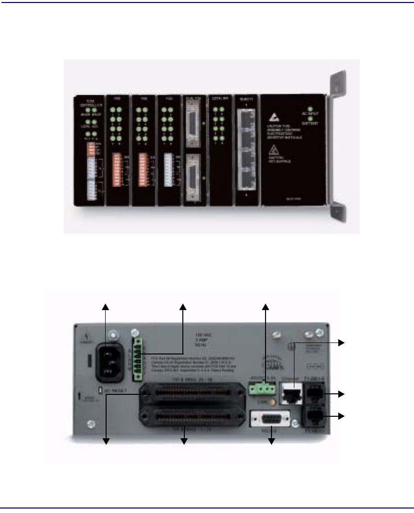
1-10 Compact T1 - Release 6.1
Base Platform
Chassis
Chassis
8.5 in (1/2 RU)
3.5 in
Service Card Slots
(2 RU)
Mounting
Bracket
10Base-T
Management
Port
-48 VDC/Battery
RS-232
2 T1/E1
Interfaces
on
Controller
Management
Port
Tip & Ring
Telco
Connector
(Lines 1-24)
Tip & Ring
Telco
Connector
(Lines 25-48)
Power SupplyController
Power Input
Alarm
Management
Port
Power Input
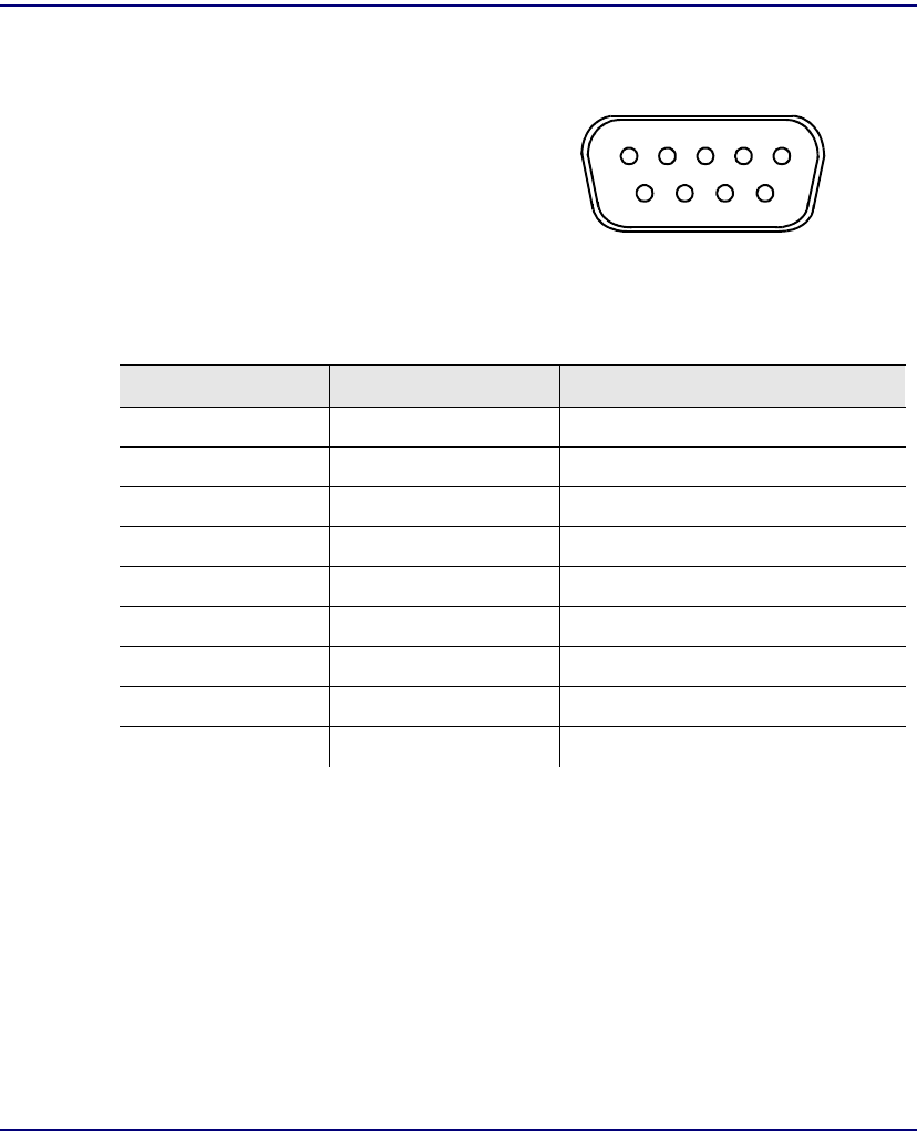
Compact T1 - Release 6.1 1-11
Base Platform
Chassis
RS-232 Craft Port (Female DB-9)
The RS-232 craft port connects via a
female DB-9 connector on the back of the
unit.
The pinouts are as follows:
Pin Number Direction Description
1 Outbound Carrier Detect
2 Outbound Receive Data
3 Inbound Transmit Data
4 Inbound Data Terminal Ready
5 Signal Ground
6 Outbound Data Set Ready
7 Inbound Request to Send
8 Outbound Clear to Send
9 Not Connected
15
69
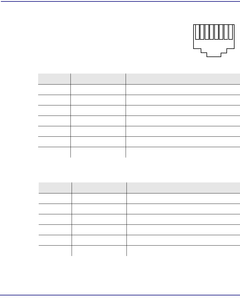
1-12 Compact T1 - Release 6.1
Base Platform
Chassis
T1 and 10Base-T Ethernet
The T1 and the 10Base-T Ethernet are female RJ-45 connectors
on the back of the unit.
The pinouts are as follows:
Ethernet (RJ-48C)
T1 (RJ-45)
Pin Name Description
1 Receive + Receive from network
2 Receive - Receive from network
3 Transmit + Transmit to network
4 N/C Not connected
5 N/C Not connected
6 Transmit - Transmit to network
7 - 8 N/C Not connected
Pin Name Description
1 Receive Ring Receive from DS1 network
2 Receive Tip Receive from DS1 network
3 N/C + Not connected
4 Transmit Ring To DS1 network
5 Transmit Tip To DS1 network
6 - 8 N/C Not connected
18


2-2 Compact T1 - Release 6.1
Physical Installation
Unpacking and Inspection
Unpacking and Inspection
WARNING! OBSERVE PRECAUTIONS FOR HANDLING ELECTROSTATIC
DEVICES.
1. Inspect containers for damage during shipment. Report any damage to the
freight carrier for possible insurance claims.
2. Compare packing list with office records. Report any discrepancies to the
office.
3. Open shipping containers, be careful not to damage contents.
4. Inspect contents and report any damage.
5. If equipment must be returned for any reason, carefully repack equipment in
the original shipping container with original packing materials if possible.
6. If equipment is to be installed later, replace equipment in original shipping
container and store in a safe place until ready to install.
Installation Environment
The environment in which you are installing the unit must meet the following
conditions:
lOperating temperature range: 32° to 104° F (0° to 40° C)
lStorage temperature range: -40° to 158° F (-40° to 70° C)
lCooling method is by free air convection, requires long axis of unit to be mounted
horizontally
lMaximum operating altitude: 10,000 ft. (3,048 m)
lMaximum non-operating altitude: 40,000 ft. (12,192 m)
lRelative humidity (non-condensing) range: 0 to 95%
For operation outside the defined environment requirements, the unit must be placed in
an environmentally controlled enclosure.
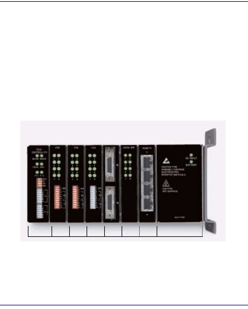
Compact T1 - Release 6.1 2-3
Physical Installation
Assembly of Unit
Assembly of Unit
The cards should be positioned in the chassis as follows:
Note: Slots are labeled on the top and the bottom of the chassis.
lPower Supply in the POWER Slot
lT1 Controller in Slot A
lService Cards can be in any slot 1 through 6.
Note: When an Unit is mounted to the wall, cards that use the front cable
connections should be loaded from Slot 6 to 1. This will minimize card access
issues due to cable interference.
lAlways install blank faceplates in any unused slots.
Service Card Slots
123456
APOWER
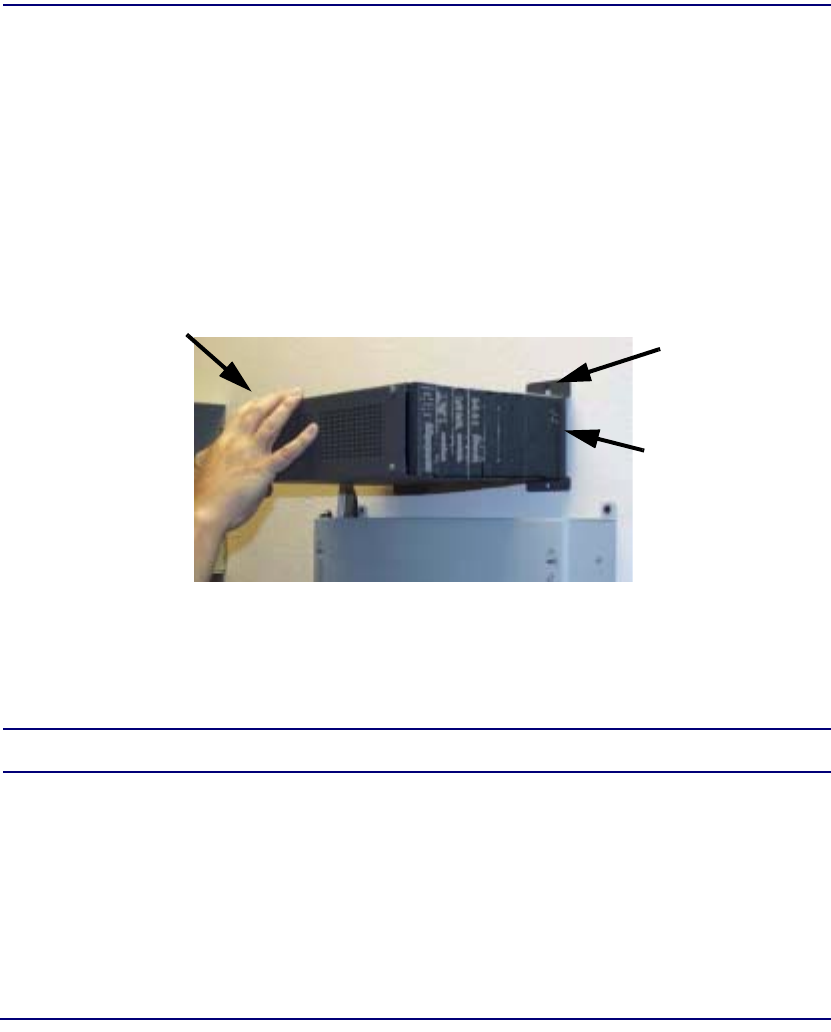
2-4 Compact T1 - Release 6.1
Physical Installation
Wall Mounting
Wall Mounting
Before beginning the mounting process, verify that the area meets the following
requirements:
lA stable environment, clean and free from extremes of temperature, shock,
vibration and EMI, that meets the all installation environment requirements, see
Installation Environment on page 2-2.
The Unit is delivered with a mounting bracket attached for quick and easy wall
mounting, as shown in the illustration above.
To install the unit to the wall, attach the unit using the four screws provided, one at each
bracket foot.
NOTE: Do not mount the Unit in any other orientation as show above.
Leave at least 3.5"
above and below
the Unit for
adequate ventilation
Mounting Bracket
Leave adequate clearance
at the back for access to
connectors
Leave at least 14" at
the front of the unit for
access to cards and
DIP switches
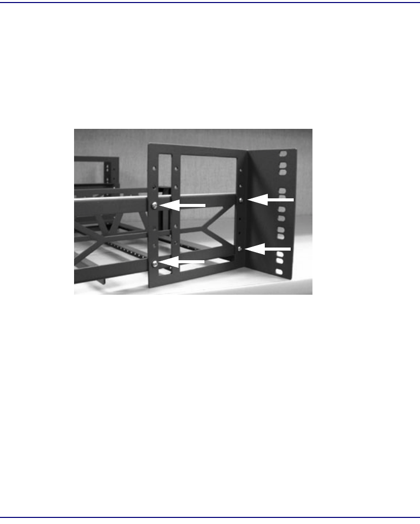
Compact T1 - Release 6.1 2-5
Physical Installation
Rack Mounting (Optional Feature)
Rack Mounting (Optional Feature)
Rack mounting kits are available for both 19 and 23 inch racks.
To rack mount the Unit, follow the instructions below:
1. Attach bracket ears to rack mounting bracket using four #8-32 x 3/16" screws
on each side.
Bracket Ear
Left Side View
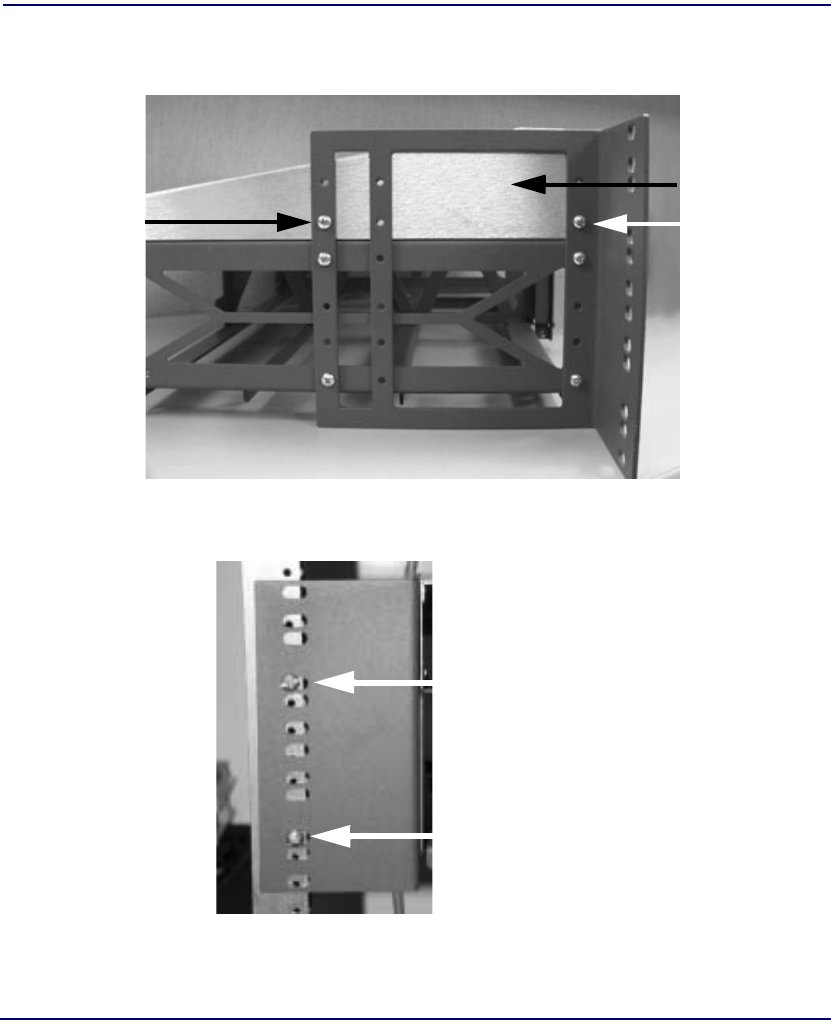
2-6 Compact T1 - Release 6.1
Physical Installation
Rack Mounting (Optional Feature)
2. Attach heat baffle to bracket ears using two #8-32 x 5/16" screws on each side.
3. Attach rack mounting bracket ears to rack using two #12-24 x 5/8" rack
mounting screws on each side.
Heat Baffle
Left Side View
Front View
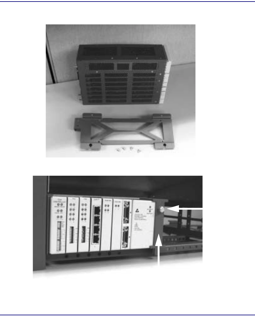
Compact T1 - Release 6.1 2-7
Physical Installation
Rack Mounting (Optional Feature)
4. Remove wall mount and screws from Unit.
5. Slide the Unit into rack mounting bracket.
6. Swing the front latch up to secure the Unit(s), and tighten thumbscrew.
Thumbscrew
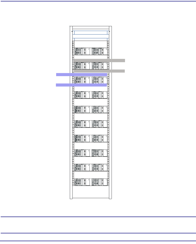
2-8 Compact T1 - Release 6.1
Physical Installation
Rack Mounting (Optional Feature)
As many as 20 Units can be mounted on a single 7 foot rack, as shown in the following
illustration (2 Adits are mounted side-by side and 10 high).
Compact T1 Chassis = 2 RUs (3.5 in) Spacing = 1 RU above and below for each unit.
NOTE: the mounting brackets are 7 inches high and will not allow units to
be mounted closer than recommended.
Compact T1 Chassis
occupies 2 RUs
1 RU free space
1 RU free space
1 RU free space
1 RU free space

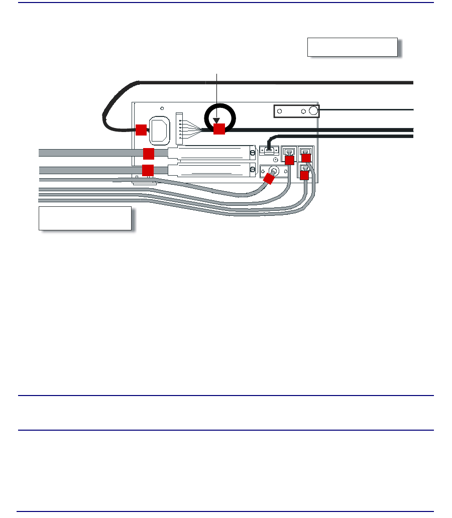
3-2 Compact T1 - Release 6.1
Electrical Installation and Cabling
Compliant Installation
Compliant Installation
1. Connect all of the signal cables as shown in the illustration above, and secure
them with a plastic tie. Dress the signal cables toward the left of the unit.
2. If using the 115V Power Supply, connect the -48 VDC battery power cable
3. Secure the ground lugs to the terminals using the nuts provided.
4. Secure the power cable and the ground cable with a plastic tie (not included).
Keep these cables separate from the signal cables.
5. Terminate each signal cable to its appropriate connector.
6. Secure the signal cables using the small holes along the bottom of the rack and
plastic ties (not included).
NOTE: It is important that the Signal Cables are secured separately from
the Power Cables, for proper equipment operation.
Power Cord
-48 VDC Battery Power
Alarm Wiring
Signal Cables
Power Cables
Grounding Cable
Ferrite Bead
with cable loop
RS-232 craft port
25-pair telco connector
25-pair telco connector
10Base-T Ethernet
T1/E1 connectors
Ferrite Beads
are in red

Compact T1 - Release 6.1 3-3
Electrical Installation and Cabling
Compliant Installation
Ferrite Beads
To be compliant with Part 15A of the FCC and for NEBS compliant facilities, the
following beads are included with each chassis, as well as additional ferrite bead(s)
with the Service cards listed below.
Ferrite Beads shipped with Adit chassis:
Service Card Cables that Require Additional Ferrite Beads:
For additional information on Ferrite beads and their installation on the unit, please
contact Customer Support.
Ferrite Provided Intended For
1 large (1) Power (AC or DC) cable
3 small (2) One on each T1 cable
(1) Ethernet (10Base-T) cable
Card Ferrites
Shipped
with Card
Intended For
ISDN BRI 2 large (1) 25-pair Telco cable (ISDN BRI card in slot 1-3 top
telco, 4-6 bottom)
(1) Alarm cable (requires a loop through the bead, see
drawing above)
OCU-DP 1 large Alarm cable (requires a loop through the bead, see
drawing above)
Quad T1 2 large T1 cables from front of Quad T1card
(1 bead can hold 1-4 cables) or,
(2) One on each 25-pair Telco cable
IP Router 1 small Ethernet Cable (from front of card)
CMG Router 1 small Ethernet Cable (from front of card)
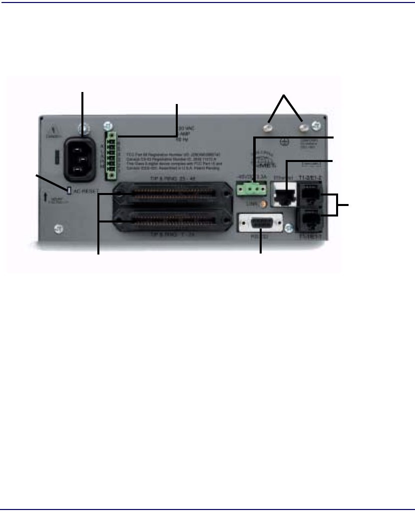
3-4 Compact T1 - Release 6.1
Electrical Installation and Cabling
Chassis Connectors and Buttons
Chassis Connectors and Buttons
The following illustrations show all connectors on the back of the unit.
Interface Connectors
The following are the Compact T1 chassis interface connectors:
lT1-1 and T1-2 line connection ports each equipped with standard
RJ-48C 8-pin connector jack
lRS-232 craft port connector
lTip and Ring Analog Interfaces equipped with standard 25-pair Telco
Connectors
l10Base-T Ethernet port to be connected to a remote management tool such as
Telnet or an SNMP-based Network Management System with an RJ-45 8-pin
connector jack
lExternal Alarm Connector
lGround Lugs
Ground Terminals
Alarms
AC Power Connector
-48V/Battery
Ethernet
T1-2
T1
RS-232 Craft Port25-Pair Telco Connectors
T1-1
[10Base-T]
Connectors
Reset
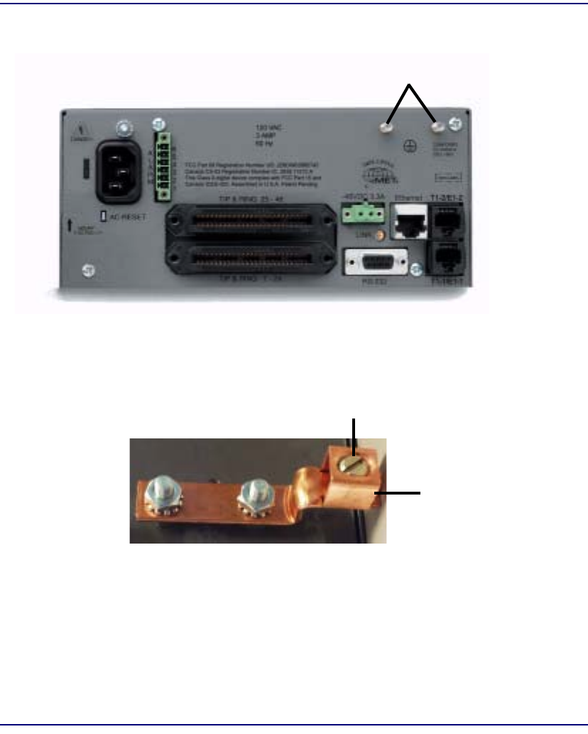
Compact T1 - Release 6.1 3-5
Electrical Installation and Cabling
Interface Connectors
Chassis Ground Connector
1. Route wire (#6 or #8 AWG copper) from building ground to lug on Unit.
2. Strip insulation off wire end, if necessary.
3. Loosen compression screw until opening is large enough to accept ground wire.
4. Insert ground wire into lug barrel, beneath compression plate and tighten
compression screw.
5. Attach ground lug to chassis
Ground Terminals
Ground Lug
Compression
Screw
Lug Barrel
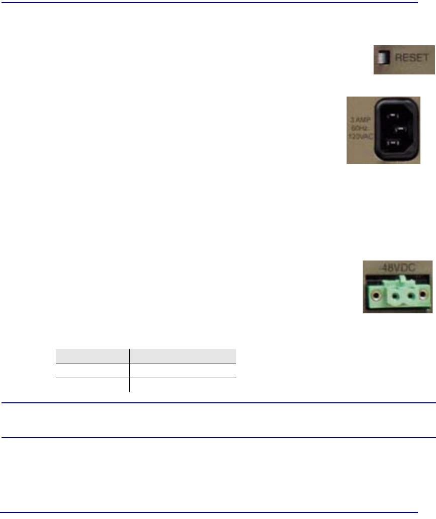
3-6 Compact T1 - Release 6.1
Electrical Installation and Cabling
Interface Connectors
Power Reset
This is a resetable circuit breaker. If at any time there is a short or power
surge on the incoming AC/DC line, the breaker will trip to protect the Power
supply from damage.
Power Connections
AC Power
The AC Power cord is a standard AC Power cord and is
provided with a 115 VAC Power Supply.
To connect the Power Cord:
1. Insert power cord (male-end) to AC power source.
2. Plug connector into the Unit.
3. A green light should appear on the DC Input LED on the front of the Power Supply.
-48V Battery
The -48 VDC input connector on the Unit is used for either direct
DC powering of the Unit or for a Battery Backup connection when
AC is used. There is no power cable provided for this connector,
however the connector is provided.
The pinouts are as follows:
WARNING! POSSIBLE SHOCK HAZARD EXISTS, PLEASE FOLLOW INSTRUCTIONS
CAREFULLY.
Pin # Description
1 (+) Battery return
2 (-) -48VDC
AC Power Connector
1(+) 2(-)
Connector
of Unit
on back
(male)
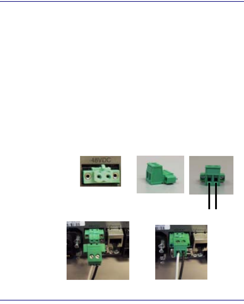
Compact T1 - Release 6.1 3-7
Electrical Installation and Cabling
Interface Connectors
To connect -48 VDC power:
1. Ensure that no power is present on the two wires to be connected.
2. Strip the two wires from the power source so that approximately 5/16 inch of
bare wire is exposed. 16 or 18 AWG insulated copper wire is recommended
for power connections.
3. Insert the Battery Return and DC wires into the appropriate square holes, one
at a time.
4. Tighten screws to clamp wires.
5. Ensure that no bare wire shows after the wires are installed.
6. Plug connector in the -48 VDC connector, as seen in the graphic and secure
with set screws.
7. Apply power to connector from -48 VDC power source.
8. Verify with voltmeter that voltage is correct and polarity is correct.
9. Plug connector in the -48 VDC connector, as seen in the graphic and secure
with set screws.
1(+) 2(-)
Connector
Provided connector (female)
of Unit
on back
(male)
Battery Return
1(+) -48 VDC
2(-)
Battery
Return (+) -48 VDC (-)

3-8 Compact T1 - Release 6.1
Electrical Installation and Cabling
Interface Connectors
External Alarm Connector
The external alarm 6-pin connector with one input pair (pins 5 and 6)
and two output pairs (pins 1 and 2 - major alarms; pins 3 and 4 - minor
alarms).
The pinouts are as follows:
Pin # Description Explanation
1 Major Alarm + The major alarm output is available for power supply or
major alarm failure alerting. The maximum voltage across
the contacts is 350 V, and the maximum current is 150 mA.
This alarm is closed when power is off.
2 Major Alarm -
3 Minor Alarm + The minor alarm output is available for power supply or
minor alarm failure alerting. The maximum voltage across
the contacts is 350 V, and the maximum current is 150 mA.
This alarm remains open when power is off.
4Minor Alarm -
5 Alarm In + The alarm inputs provide 5 VDC across the two contacts,
and generate an alarm when a short circuit is detected
between the contacts.
The alarm generated is a minor severity alarm.
6 Alarm In -
6
5
4
3
2
1
A
L
A
R
M

Compact T1 - Release 6.1 3-9
Electrical Installation and Cabling
Interface Connectors
25-Pair Telco Connectors
Tip and Ring Analog Interfaces equipped with standard 25-pair Telco Connectors
(female) for connection to key systems, fax machines, modems, and PBXs. These
interfaces are also used for ISDN BRI ports and are jumper selectable on the Quad T1
card.
Circuit connections are made at the 25-pair
telco connectors. A standard 25-pair
telephone cable with RJ-21X wiring and a
male D-type connector at the Unit end is
required.
The pinouts are as follows:
Pair Pin Location Function Color Code
126
1Tip Channel 1
Ring Channel 1 White/Blue
Blue/White
227
2Tip Channel 2
Ring Channel 2 White/Orange
Orange/White
328
3Tip Channel 3
Ring Channel 3 White/Green
Green/White
429
4Tip Channel 4
Ring Channel 4 White/Brown
Brown/White
530
5Tip Channel 5
Ring Channel 5 White/Slate
Slate/White
631
6Tip Channel 6
Ring Channel 6 Red/Blue
Blue/Red
732
7Tip Channel 7
Ring Channel 7 Red/Orange
Orange/Red
833
8Tip Channel 8
Ring Channel 8 Red/Green
Green/Red
934
9Tip Channel 9
Ring Channel 9 Red/Brown
Brown/Red
10 35
10 Tip Channel 10
Ring Channel 10 Red/Slate
Slate/Red
50
25
26
1

3-10 Compact T1 - Release 6.1
Electrical Installation and Cabling
Interface Connectors
Pair Pin Location Function Color Code
11 36
11 Tip Channel 11
Ring Channel 11 Black/Blue
Blue/Black
12 37
12 Tip Channel 12
Ring Channel 12 Black/Orange
Orange/Black
13 38
13 Tip Channel 13
Ring Channel 13 Black/Green
Green/Black
14 39
14 Tip Channel 14
Ring Channel 14 Black/Brown
Brown/Black
15 40
15 Tip Channel 15
Ring Channel 15 Black/Slate
Slate/Black
16 41
16 Tip Channel 16
Ring Channel 16 Yellow/Blue
Blue/Yellow
17 42
17 Tip Channel 17
Ring Channel 17 Yellow/Orange
Orange/Yellow
18 43
18 Tip Channel 18
Ring Channel 18 Yellow/Green
Green/Yellow
19 44
19 Tip Channel 19
Ring Channel 19 Yellow/Brown
Brown/Yellow
20 45
20 Tip Channel 20
Ring Channel 20 Yellow/Slate
Slate/Yellow
21 46
21 Tip Channel 21
Ring Channel 21 Violet/Blue
Blue/Violet
22 47
22 Tip Channel 22
Ring Channel 22 Violet/Orange
Orange/Violet
23 48
23 Tip Channel 23
Ring Channel 23 Violet/Green
Green/Violet
24 49
24 Tip Channel 24
Ring Channel 24 Violet/Brown
Brown/Violet
25 50
25 Reserved Violet/Slate
Slate/Violet
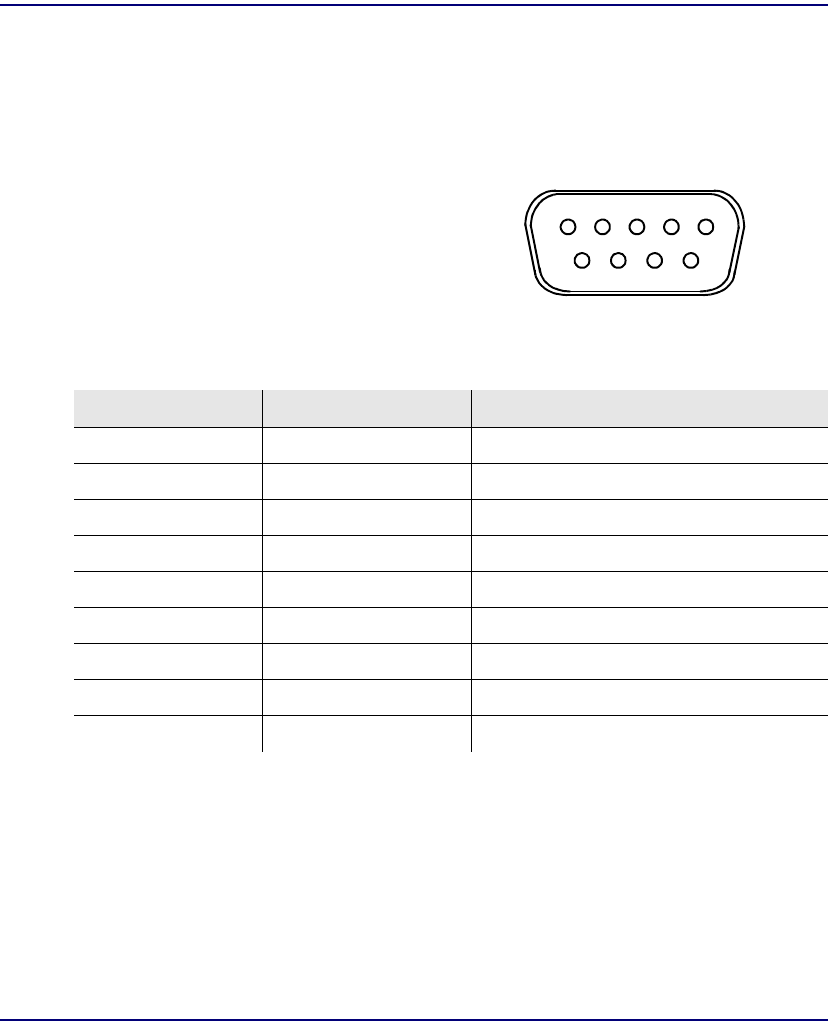
Compact T1 - Release 6.1 3-11
Electrical Installation and Cabling
Interface Connectors
RS-232 Craft Port (Female DB-9)
The RS-232 craft port connector (female) is for connection to an external PC or Hayes-
compatible modem for local or remote configuration, management, and performance
monitoring using the Command Line Interface (CLI).
The RS-232 craft port connects via a
female DB-9 connector on the Unit.
The pinouts are as follows:
Pin Number Direction Description
1 Outbound Carrier Detect
2 Outbound Receive Data
3 Inbound Transmit Data
4 Inbound Data Terminal Ready
5 N/A Signal Ground
6 Outbound Data Set Ready
7 Inbound Request to Send
8 Outbound Clear to Send
9 N/C Not connected
15
69
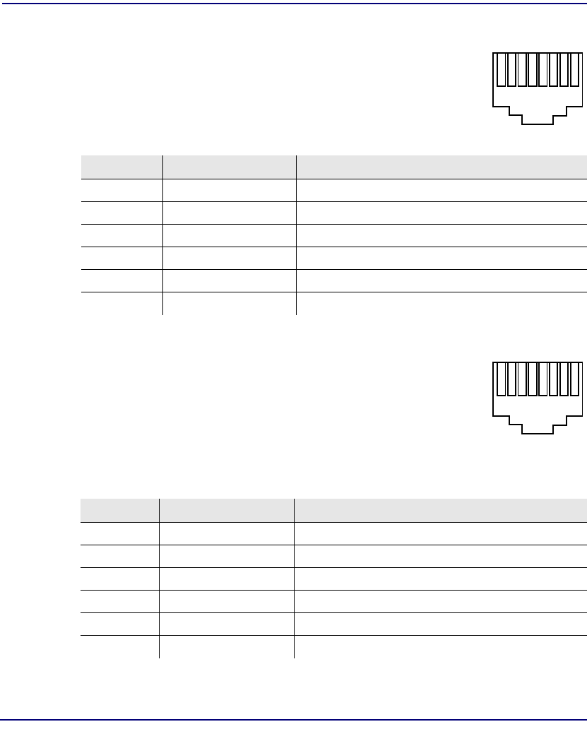
3-12 Compact T1 - Release 6.1
Electrical Installation and Cabling
Interface Connectors
T1 Connection Ports
The T1 connection ports are each equipped with a standard RJ-48C
(female) on the Unit.
The pinouts are as follows:
T1 (RJ-48C)
10Base-T Ethernet
The 10Base-T Ethernet (female) port to connect to a remote
management tool such as Telnet or an SNMP-based Network
Management System. Note a LINK LED on the back of the unit
displays green when the system has a good ethernet link.
The pinouts are as follows:
Ethernet (RJ-45)
Pin Name Description
1 Receive Ring Receive from DS1 network
2 Receive Tip Receive from DS1 network
3 N/C Not connected
4 Transmit Ring To DS1 network
5 Transmit Tip To DS1 network
6 -8 N/C Not connected
Pin Name Description
1 Receive + Receive from network
2 Receive - Receive from network
3 Transmit + Transmit to network
4 - 5 N/C Not connected
6 Transmit - Transmit to network
7 - 8 N/C Not connected
18
18

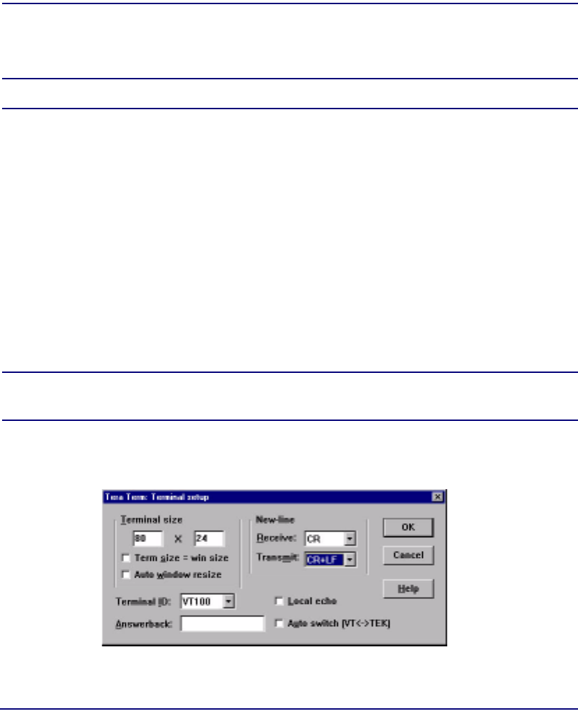
4-2 Compact T1 - Release 6.1
Configuration
Setting up a CLI Connection
Setting up a CLI Connection
NOTE: Default IP address of the Controller (T1) is 10.0.0.10.
To connect with CLI, set up the connection:
lIf connecting via the ethernet 10Base-T connection, use a Telnet TCP/IP
program to access the CLI. This requires an IP address of the Controller. The
Controllers are shipped with the IP address set to 10.0.0.10, if this address has
been changed and is not known, use Hyperterm to access the Controller and use
the CLI command show ip. If an IP address needs to be set use the CLI
command set ethernet ip address.
lIf connecting via RS-232, the port settings should be set to:
Bits per second: 9600 Data bits: 8
Parity: None Stop bits: 1
Flow control: None
lSet your Terminal Emulation to: VT100
NOTE: Note: When using Tera Term TCP/IP, CLI commands will not be
recognized until the following setup is completed.
lIn Tera Term go to Setup/Terminal.
lSet the New-line/Transmit value"CR+LF".
Local vs. Remote Configuration
lFor remote configuration via the CLI, use the set local off command.

Compact T1 - Release 6.1 4-3
Configuration
System Information
System Information
Once a management session has bee initiated (Telnet or Hyperterm) the system
information will be displayed similar to the following:
00:00:38 01/01/2002
Status Equipment:
BootCode Version: 1.22
CardType Status SW Vers CLEI
SLOT A T1x2 Present 6.0.0 SIC3DH0CAA
SLOT 1 FXS5Gx8 Not Present
SLOT 2 RTRx1 Present 1.41 NOT AVAIL
SLOT 3 FXS5Gx8 Present 1.06 NOT AVAIL
SLOT 4 CMGx1 Present 1.00 SIIX270DAA
SLOT 5 BRIx4 Not Present
SLOT 6 OCUDPx1 Present 1.01 SIIXA4DDAA
Alarms:
Time Date Severity Description
00:00:22 01/01/2002 Major 6:1-OCUDP Out of Service
00:00:21 01/01/2002 Major 6:1-OCUDP Loss of Signal
00:00:15 01/01/2002 Major 4:1-CMG Ethernet Link Down
00:00:15 01/01/2002 Major 2:1-RTR Ethernet Link Down
00:00:06 01/01/2002 Major A:2-DS1 Loss Of Signal
00:00:06 01/01/2002 Major A:1-DS1 Loss Of Signal
Total=6
Status Sessions:
Session User Login Port
* TELNET1 192.168.43.52
* indicates current session
Show Autoexit:
Autoexit is on; timeout is 20 minutes.
>

4-4 Compact T1 - Release 6.1
Configuration
Basic System Setup
Basic System Setup
Following is a quick reference to some of the common tasks in configuring the
Unit.
Initial Setup
Use the following commands for your initial setup, for further information see the
specific command listed in Chapter 5, CLI Commands .
Command Description
set local off Disables DIP switches.
set date {mm/dd/yyyy} Set the date used for event logging
set time {hh:mm:ss} Set the time used for event logging
set id {"id-name"} Set a system ID name
set clock1 {slot:port}
internal
Set the primary clock source
set clock2 {slot:port}
internal
Set the secondary clock source
set ethernet ip address
{ip-addr} {mask}
Set the ethernet IP address, in the
conventional IP address format
set ip gateway {ip-addr} Set the IP gateway, in the conventional IP
address format

Compact T1 - Release 6.1 4-5
Configuration
Basic System Setup
Set Up Security
Use the following commands to set up the security on the Unit. See the set user
command for details.
Set Up a DS1/T1
Use the following commands to set up a DS1. See the set (ds1) command for more
details.
Command Description
set user {"user-name"}
level {1-3}
Specify the user name and the security level
set user {"user-name"}
password
Set a password for the user
Command Description
set {ds1-addr} up Activate the port of the DS1 (slot:port)
set {ds1-addr} id
{"id-string"}
Set the identification string
set {ds1-addr} lbo {1 - 9} Set the line buildout value for the DS1
set {ds1-addr} linecode
{ami|b8zs}
Set the linecode for the DS1
set {ds1-addr} framing
{d4|esf|tr8afdl|tr8anofdl|
tr8b}
Set the framing option for the DS1
set {ds1-addr} loopdetect
{on|off}
Set the detection/reaction to CSU loopcodes

4-6 Compact T1 - Release 6.1
Configuration
Basic System Setup
Set Up a DS0/Channel
Use the following commands to set up a DS0. See the set (ds0) command for details.
Set Up an Analog Port
Use the following commands to set up an analog port.
Command Description
set {slot:port:channel} up Activate the channel
set {slot:port:channel} signal
{ls|gs|emw|emdw|emicpd|dpt}
Set the signaling option for the channel
set {slot:port:channel} type
{data|voice}
Set the channel type
Command Description
set {slot:port} up Activate the port. See set (ds1) command
for details
set {slot:port} signal
{dpt|gs|gsrb|gsw|gswrb|ls|
lscpd|lsrb}
Set the signaling option for the port. See the
set (fxs5G) or set (fxo) command for details
set {slot:port} rxgain {n} Set the receive gain/loss in dB. See the set
(fxs5G) or set (fxo) command for details
set {slot:port} txgain {n} Set the transmit gain/loss in dB. See the set
(fxs5G) or set (fxo) command for details

Compact T1 - Release 6.1 4-7
Configuration
Basic System Setup
Set Up the Router Card
The following is the basic setup, see the Adit Router User Manual or Quick Start
Guide for the following configuration setups:
lPPP Internet Connection and Public IP Address Routing
lFrame Relay Internet Connection and Public IP Address Routing
lInternet Connection using PPP, NAT/PAT and Firewall Filters
lInternet Connection using NAT and Static NAT Addresses
lPPP Internet Connection and Public IP Address Routing
lBack-to-Back with PPP
Command Description
set {ds0-addr} type data Confirm DS0 is set to type data.
ds0-addr = {slot:port:channel} of DS0
Example: set a:1:1-24 type data
connect {slot:port:trunk}
{slot:port:channel}
Cross-connect T1 to router card.
Example: connect a:1:1-24 6:1:1 (router in slot 6)
set {router-addr} proxy Disable/enable router proxy.
router-addr = {slot:port}| of router card.
Example: set 6:1 proxy disable.
set {slot:port} up Set Router LAN as In-Service.
Example: set 6:1 up
telnet {router_card-addr} Telnet to Router card.
router_card-addr = {slot} location of router card
Example: telnet 6 (if earlier than 3.0 release {slot:port}
must be used)
Local and Remote Profile Setup
reinitialize To enable any configuration changes, the card must be
reinitialized.

4-8 Compact T1 - Release 6.1
Configuration
Basic System Setup
Establish a Static Channel Connection
Use the following commands to establish a static channel connection.
Set Up a ISDN BRI Service
Use the following commands to set up a ISDN BRI Service. See the set (bri) command
for details.
Command Description
set {slot:port:channel} type
{voice|data}
Set the channel type for the channel you
want to map. See set (ds0) command for
details
set {slot:port:channel} signal
{emdw|emi|emicpd|emw|gs|ls|pl
ar|r2}
Set the signaling option for the channel you
want to map. See set (ds0) command for
details
connect {slot:port}
{slot:port}
Connect the channels. See the show connect
command for details
Command Description
set {slot:port} up Put the ISDN line In-Service
set {slot} mode
{lt3ds0|lt4to1tdm|nt3ds0}
Set the ISDN mode
set {slot:port} crv {1-768} Set the Call Reference Value.
set {slot:port} threshold
{day|hour} {es|ses}
Set the threshold for the IDSN lines
set {slot} pmsync
{adit|switch}
Set the source for performance monitoring
synchronization
set {slot:port} autoactivate
{on|off}
Only used in 4 to 1 mode. Establishes the D
channel when the FDL link can not be used

Compact T1 - Release 6.1 4-9
Configuration
Basic System Setup
Set Up the OCU-DP Card
The following is a basic setup for the OCU-DP card.
Command Description
set {ocudp-addr} baud
{2400|4800|9600|19200|38400|
56000*|64000}
Set the OCU-DP Baud rate.
Where ocudp-addr = {slot:port} of the
OCU-DP card to apply settings to
set {ocudp-addr} up Set the OCU-DP port 1 up
show {ocudp_card-addr} Show the OCU-DP card settings.
Where ocudp_card-addr = {slot} of the
OCU-DP card
disconnect a Disconnects all connections to slot a
(controller)
set {ds0-addr} type data Sets a DS0 data signaling type
connect {ds0-addr}
{ocudp-addr}
Connects DS0 (in previous step) to OCU-DP
port (in previous step)
show connect
(ocudp_card-addr}
Displays connect information for OCU-DP
card

4-10 Compact T1 - Release 6.1
Configuration
Basic System Setup
Set Up a V.35 Port
Use the following commands to set up a V.35 port. See the set (v35) command for
details.
Change the IP Address of the DS0 Management Channel
Use the following commands to change the IP over DS0 Management Channel for the
Unit.
Command Description
set {slot:port} cts
{cd|high|low|rts}
Set the Clear to Send operation mode
set {slot:port} data
{invert|normal}
Set the data mode
set {slot:port} clock
{source|external}
Set the clock mode
set {slot:port} speed
{56K|64K}
Set the speed
set {slot:port} txclkinv
{invert|normal}
Set the transmit clock inversion mode
set {slot:port} rxclkinv
{invert|normal}
Set the receive clock inversion mode
Command Description
set ipds0 down Set the DS0 management channel down
set ipds0 ip address
{ip-addr}
Set the DS0 management channel IP
address.
set ipds0 up Set the DS0 management channel up

Compact T1 - Release 6.1 4-11
Configuration
Basic System Setup
Upgrade the Controller Software
Use the following commands to determine the system software level, then upgrade the
software to the latest version.
Upgrade the Router (IP or CMG) Software
Use the following commands to determine the Router card software level, then upgrade
the software to the latest version.
Command Description
status equipment Determine the system software level. The
Slot A line (SW Vers) will display the
current software level
load tftp {ip-addr} {"file-
name"} (or load xmodem)
Load the new controller system software.
See the load tftp and load xmodem
command for more information. Note: must
have TFTP running in the background
Command Description
status equipment Determine the Router software level. The
Router Slot line (SW Vers) will display the
current software level
load {router-slot} tftp
{ip-addr} {"file-name"}
Load the new Router software to the Adit
Router card. See the load tftp command for
more information. Note: must have TFTP
running in the background
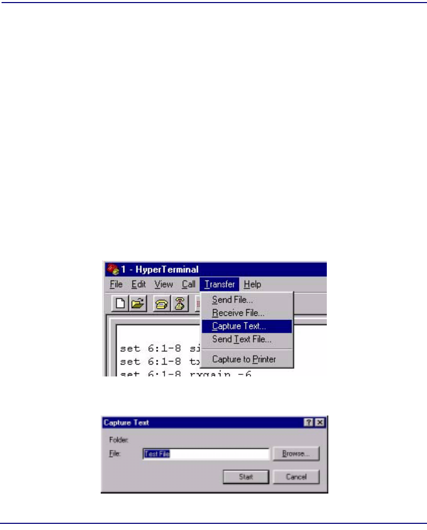
4-12 Compact T1 - Release 6.1
Configuration
Quick Configuration Reload
Quick Configuration Reload
The print config command can be used as a quick way to reload a configuration into
an Adit unit, in the event that the configuration has been lost due to software reload
problems or operator error.
The download of the file generated by the print config command can be done by direct
connect to the RS-232 port or via Telnet, BUT the upload from the PC back to the Adit
can only be done via direct RS-232 connection. The reason for this is that there will not
be an IP address in the Adit because it is at the factory default at this time.
The procedure described below is based on using Hyperterm.
Download Config File:
1. Connect to the unit using Hyperterm via the RS-232 port.
2. Type print config (do not hit [ENTER]).
3. Select Transfer/Capture Text... from the menu bar.
4. Name the file so that is can be accessed when needed.
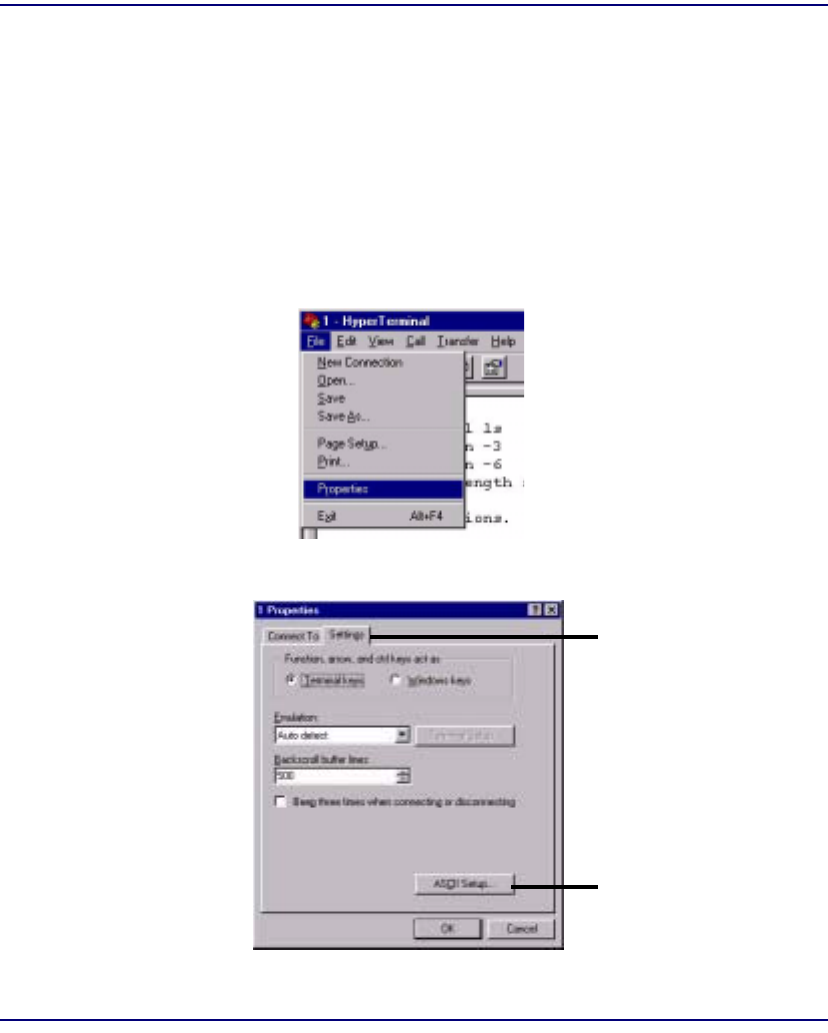
Compact T1 - Release 6.1 4-13
Configuration
Quick Configuration Reload
5. Select the [START] button, the window will close and the operator will be
returned to the Adit command line.
6. Press [ENTER] to download. Adit will generate an executable file of all
configurable commands and save it to the file location defined above.
7. The download is complete when the text has finished scrolling on the screen
and the Adit ID prompt displays again.
Load Config File Back to Unit:
1. Select File/Properties from the menu bar.
2. Select the Settings tab.
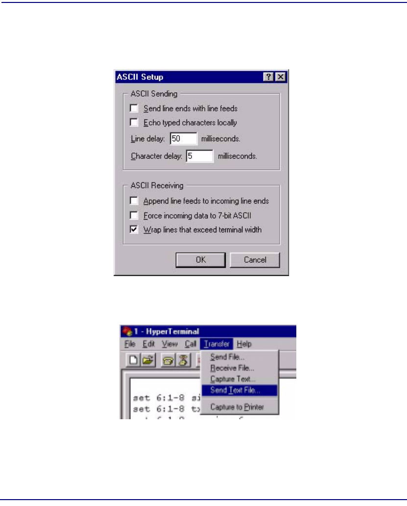
4-14 Compact T1 - Release 6.1
Configuration
Quick Configuration Reload
3. Select the ASCII Setup button.
4. Set the Line delay to 50 milliseconds and the Character delay to 5
milliseconds.
5. Select the [OK] button back to the Main HyperTerminal screen.
6. Select Transfer/Send Text File.. from the menu bar.
Hyperterm will now send the configuration to the Adit exactly as it was saved in
the Download Config File process.
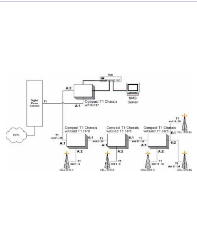
Compact T1 - Release 6.1 4-15
Configuration
Setup of DS0 Management Channel
Setup of DS0 Management Channel
The DS0 Management Channel provides SNMP management and remote access. The
IPDS0 feature allows for full Transmission Control Protocol/Internet Protocol
(TCP/IP) connectivity to remote Compact T1 and can be used for Simple Network
Management Protocol (SNMP) trap reporting and configuration, Trivial File Transfer
Protocol (TFTP) upgrades of Controllers and Service cards, and remote telnet access.
The following procedure will walk you through the basic setup of a DS0 Management
Channel.

4-16 Compact T1 - Release 6.1
Configuration
Setup of DS0 Management Channel
Equipment Required
lDCS
l(1) Collocated Router
This example uses a Compact T1 (version 2.0 or later) with an Compact T1
Router card (version 1.10 or later)
lRemote Compact T1 (1-24) Units (version 2.0 or later)
lPC
lCables, Ethernet, T1
Application Overview
lIPDS0 management provides a TCP/IP connection to an Compact T1
Controller via an unused DS0 on one of the DS1 ports in slot A. The DS0 is
connected to a Router on a Frame Relay circuit with a default Data Link
Connection Identifier (DLCI) number of 16. IP communication to the remote
Units is made via the Ethernet port of the Router card.
lRemote Units are daisy-chained to the central site and are also configured to
communicate with a Network Management Station (NMS) using SNMP.
lCentral site Compact T1 and IP Router card are configured to communicate
with the same NMP.
Operation
lCentral Site Compact T1 - Incoming DS0s for cell services are delivered on the
first T1 in slot A. The channels are then cross-connected to the second T1 span
on the Controller, along with IPDS0 connections from the Router card.
lCompact T1 at remote locations - Available DS0s are delivered on the first T1
in slot A, and the channels are either connected to the IPDS0 management
interface, the second T1 span of the Controller (for local cell services), or
passed on to the next Remote Unit on the first T1 span of the Quad T1 card in
slot 6. In the configuration for Site C, the 4 channels on the second T1 span in
slot A and 4 channels of the first and second T1 spans in slot 6 are connected
to cell sites.

Compact T1 - Release 6.1 4-17
Configuration
Setup of DS0 Management Channel
Provision DS0s for data and cross-connect to the
outgoing T1
Configure the Router
Command Description
disconnect a Disconnects all connections to slot a (controller)
set a:1:all type data Sets all DS0s on T1-1 to data signaling type
set a:2:all type data Sets all DS0s on T1-2 to data signaling type
connect a:1:1-4 a:2:1-4 Connects first four DS0s of T1-1 of the controller to
first four DS0s of T1-2.
connect a:1:6-9 a:2:6-9 Connects DS0s 6-9 of T1-1 of the controller to
DS0s 6-9 of T1-2.
connect a:1:11-14 a:2:11-14 Connects DS0s 11-14 of T1-1 of the controller to
DS0s 11-14 of T1-2.
connect a:1:15-19 a:2:16-19 Connects DS0s 16-19 of T1-1 of the controller to
DS0s 16-19 of T1-2.
connect a:1:21-24 a:2:21-24 Connects DS0s 21-24 of T1-1 of the controller to
DS0s 21-24 of T1-2.
Command Description
set 6 default Sets the Router in slot 6 to it’s default settings
add 6 snmp trap "public"
192.168.0.254 "LocalUnit"
Configure the Router card trap address
set 6:1 ip address
192.168.0.1 255.255.255.0
Configure the LAN IP address
set 6 lmi disable Disable PVC management for Frame Relay connections
connect a:2:5 6:1:1 Connect the timeslot to the WAN port.

4-18 Compact T1 - Release 6.1
Configuration
Setup of DS0 Management Channel
Setup the Profile for Site A
Setup the Profile for Site B
Command Description
rename 5 "RemoteUnit" "SITE-
A"
Configure the LAN IP address
set 6:1:1 encapsulation fr Specify the encapsulation for the profile
set 6 "SITE-A" trunk 1 Specify the trunk number for the profile
set 6 "SITE-A" dlci 16 Specify the DLCI number for the profile
set 6 "SITE-A" up Enable the profile
add 6 "SITE-A" static ip
network 192.168.1.101
255.255.255.255 1
Specify the IP address of the Compact T1 at the far end
Command Description
connect a:2:10 6:1:2 Connect the timeslot to the WAN port.
add 6 remote "SITE-B" Add another WAN profile named SITE-B
set 6:1:2 encapsulation fr Specify the encapsulation for the profile
set 6 "SITE-B" trunk 2 Specify the trunk number for the profile
set 6 "SITE-B" dlci 16 Specify the DLCI number for the profile
set 6 "SITE-B" up Enable the profile
add 6 "SITE-B" static ip
network 192.168.1.102
255.255.255.255 1
Specify the IP address of the Compact T1 at the far end

Compact T1 - Release 6.1 4-19
Configuration
Setup of DS0 Management Channel
Setup the Profile for Site C
Remote Site A Configuration
Command Description
connect a:2:15 6:1:3 Connect the timeslot to the WAN port.
add 6 remote "SITE-C" Add another WAN profile named SITE-C
set 6:1:3 encapsulation fr Specify the encapsulation for the profile
set 6 "SITE-C" trunk 3 Specify the trunk number for the profile
set 6 "SITE-C" dlci 16 Specify the DLCI number for the profile
set 6 "SITE-C" up Enable the profile
add 6 "SITE-C" static ip
network 192.168.1.103
255.255.255.255 1
Specify the IP address of the Compact T1 at the far end
set snmp nms 1 192.168.0.254 Set up SNMP Trap address for the Compact T1
Command Description
disconnect a Disconnects all connections to slot a (controller)
set a:1:all type data Sets all DS0s on T1-1 to data signaling type
set a:2:all type data Sets all DS0s on T1-2 to data signaling type
disconnect 6 Disconnects the router in slot 6
set 6:1:all type data Sets all DS0s on slot 6 to data signaling type
connect a:1:1-4 a:2:1-4 Connect channels to cell site
set ipds0 assign a:1:5 Assign channel to IPDS0 management channel
set ipds0 ip address
192.168.1.101 255.255.255.0
Configure IPDS0 ip address
set ipds0 up Enable IPDS0
set ipds0 navalarm off Suppress IPDS0 alarm
set snmp nms 1 192.168.0.254 Set up SNMP Trap address for the Compact T1

4-20 Compact T1 - Release 6.1
Configuration
Setup of DS0 Management Channel
Remote Site B Configuration
Command Description
disconnect a Disconnects all connections to slot a (controller)
set a:1:all type data Sets all DS0s on T1-1 to data signaling type
set a:2:all type data Sets all DS0s on T1-2 to data signaling type
disconnect 6 Disconnects the router in slot 6
set 6:1:all type data Sets all DS0s on slot 6 to data signaling type
connect a:1:6-9 a:2:1-4 Connect channels to cell site
connect a:1:11-24 6:1:11-24 Connect channels for outgoing T1 port
set ipds0 assign a:1:10 Assign channel to IPDS0 management channel
set ipds0 ip address
192.168.1.102 255.255.255.0
Configure IPDS0 ip address
set ipds0 up Enable IPDS0
set ipds0 navalarm off Suppress IPDS0 alarm
set snmp nms 1 192.168.0.254 Set up SNMP Trap address for the Compact T1

Compact T1 - Release 6.1 4-21
Configuration
Setup of DS0 Management Channel
Remote Site C Configuration
Test
After configuring all the Compact T1, verify connectivity to the NMS from each Unit.
> Ping 192.168.0.254
Response should be:
>192.168.0.254 is reachable
Command Description
disconnect a Disconnects all connections to slot a (controller)
set a:1:all type data Sets all DS0s on T1-1 to data signaling type
set a:2:all type data Sets all DS0s on T1-2 to data signaling type
disconnect 6 Disconnects the router in slot 6
set 6:1:all type data Sets all DS0s on slot 6 to data signaling type
connect a:1:11-14 a:2:1-4 Connect channels to cell site C
connect a:1:16-19 6:1:1-4 Connect channels to cell site D1
connect a:1:21-24 6:2:1-4 Connect channels to cell site D2
set ipds0 assign a:1:15 Assign channel to IPDS0 management channel
set ipds0 ip address
192.168.1.103 255.255.255.0
Configure IPDS0 ip address
set ipds0 up Enable IPDS0
set ipds0 navalarm off Suppress IPDS0 alarm
set snmp nms 1 192.168.0.254 Set up SNMP Trap address for the Compact T1

4-22 Compact T1 - Release 6.1
Configuration
Setup of DS0 Management Channel


5-2 Compact T1 - Release 6.1
CLI Commands
Command Line Interface Help
During a CLI session, help is available at any time.
? or help
Type a ? (or "help" before a command) at any time for quick command information
> add ?
add ..................... Create users or profiles
{rtr_card-addr} ...... Create profile, object or service on a router
{rtr_lan-addr} ....... Create object or service on the router LAN
user ................. Create user with manager level access.
NOTE: The scrolling feature, will always scroll through the command/
options in alphabetical order.
[TAB] usage for word or command completion
Use [TAB] for command word completion:
> sh [TAB]
> show
Use [TAB] to view command levels:
> [TAB] will scroll through the base commands
> aco [TAB]
> add [TAB]
> alarms [TAB]
> clear [TAB]
> connect [TAB]
> delete ... etc.

Compact T1 - Release 6.1 5-3
CLI Commands
Use [TAB] to view command options, add a space after the base command with the use of
the [TAB] feature, scroll through all available options for this command:
> set [TAB] will scroll through the set commands, with each <TAB>
> set alarms [TAB]
> set autoexit [TAB]
> set clock1 ... etc.
If another space is placed after the command and [TAB] is pressed again, the next
command level will display (if any):
> set snmp [TAB] will scroll through all the set SNMP options
> set snmp contact [TAB]
> set snmp getcom [TAB]
> set snmp location [TAB]
> set snmp name ... etc.

5-4 Compact T1 - Release 6.1
CLI Commands
CLI Commands
For maneuverability through these commands, all command names in blue or italics
are hyperlinked.
aco (Alarm Cut Off) ping
add print
alarms rename (router)
clear reset
connect restore
delete rtrping
disconnect set
exit show
install status
load store
log telnet

Compact T1 - Release 6.1 5-5
CLI Commands
aco (Alarm Cut Off)
aco (Alarm Cut Off)
Use the aco command to activate the Alarm Cut Off, which opens the alarm relay contacts on
the back of the unit.
Syntax: aco
Example: aco
ACO LED
To turn off ACO, all alarms must be cleared, or the operator can reset the controller, which will
set the ACO back to the default (off) state.
Off Normal mode. No alarms are being suppressed.
Yellow Alarm cutoff active. One or more active alarms suppressed.

5-6 Compact T1 - Release 6.1
CLI Commands
add
add
Use the add command to create users, interfaces, services or profiles.
See the following sections for detailed information on the following add commands
add (router) dns proxy
add (router) remote
add (router) snmp community
add (router) snmp trap
add (router) static dns host
add (router) uploaduser
add (router-lan) filter
add (router-lan) secondary ip address
add (router-lan) static
add (router-wan) firewall
add (router-wan) gre network
add (router-wan) nat bypass
add (router-wan) static
add user

Compact T1 - Release 6.1 5-7
CLI Commands
add
add (router) dns proxy
Use the add (router) dns proxy command to enable DNS proxy and add a remote DNS server
address to the specified Router card.
Syntax: add {rtr_card-addr} dns proxy {"domain-name"}
{ip-addr} {"profile-name"}
Example: add 2 dns proxy "Domain1" 192.168.100.245 "Texas"
Example will add a DNS proxy server "Domain1" with address
192.168.100.245 to the WAN named "Texas" on the Router in slot 2.
{rtr_card-addr}
The slot number (1-6) that contains the Router (IP or CMG) card.
{"domain-name"}
The domain name for the external DNS server. Name must be enclosed in quotes, with a
maximum length of 42 characters.
{ip-addr}
The IP address of the external DNS server, in the form of xxx.xxx.xxx.xxx, where xxx is
between 0-255.
{"profile-name"}
The profile name for the Router interface that is used to reach this destination. Name must
be enclosed in quotes, with a maximum length of 11 characters.
add (router) remote
Use the add (router) remote command to add a remote WAN profile to the WAN profile table
on the specified Router card.
Syntax: add {rtr_card-addr} remote {"profile-name"}
Example: add 6 remote "Texas"
The example will add a remote WAN named "Texas" to the WAN profile table
for the Router in slot 6.
{rtr_card-addr}
The slot number (1-6) that contains the Router (IP or CMG) card.
{"profile-name"}
The name of the remote WAN profile to add with a maximum length of 11 characters. This
name must be enclosed in quotes.

5-8 Compact T1 - Release 6.1
CLI Commands
add
add (router) snmp community
Use the add (router) snmp community command to add a SNMP community to an interface
on the specified Router card.
Syntax: add {rtr_card-addr} snmp community {both|read|write}
{"community-name"} {ip-addr}
Example: add 2 snmp community both "commune" 192.168.100.245
The example will allow the host 192.168.100.245 read/write access to the
Router card SNMP agent using the community name "commune". The Router is
located in slot 2.
{rtr_card-addr}
The slot number (1-6) that contains the Router (IP or CMG) card.
{both|read|write}
{"community-name"}
Name of the community to add with a maximum length of 10 characters. Must be enclosed
in quotes.
{ip-addr}
The IP address of the host that can access the SNMP agent via this community, in the form
of xxx.xxx.xxx.xxx, where xxx is between 0-255. The address "0.0.0.0" allows any host.
both Will set the community to be read/write
read Will set the community to be read-only
write Will set the community to be write-only

Compact T1 - Release 6.1 5-9
CLI Commands
add
add (router) snmp trap
Use the add (router) snmp trap command to specify a destination to send SNMP trap
messages for the specified Router card.
Syntax: add {rtr_card-addr} snmp trap
{"community-name"} {ip-addr} {"profile-name"}
Example: add 3 snmp trap "commune" 192.168.100.245 "RemoteAdit"
The example will add a trap destination of 192.168.100.245 on the interface
"RemoteAdit" and use the community name "commune" in the messages. The
Router is located in slot 3.
{rtr_card-addr}
The slot number (1-6) that contains the Router (IP or CMG) card.
{"community-name"}
The community name to use in each trap message, with a maximum of 10 characters.
{ip-addr}
The IP address of the destination trap to add, in the form of xxx.xxx.xxx.xxx, where xxx is
between 0-255.
{"profile-name"}
The profile name for the Router interface that is used to reach this destination. Maximum
of 11 characters and this name must be enclosed in quotes.

5-10 Compact T1 - Release 6.1
CLI Commands
add
add (router) static dns host
Use the add (router) static dns host command to add a static DNS host record for resolving a
domain name to an IP address if the DNS server cannot provide the information. The DNS
resolver will first attempt to resolve the name by querying the configured DNS servers. If this
does not yield the information, the DNS resolver will consult this list of static entries. This
command will fail if the DNS resolver is not enabled.
Syntax: add {rtr_card-addr} static dns host
{ip-addr} {"domain-name"}
Example: add 2 dns host 192.168.100.245 "myhost.some.net"
Example will add a static DNS host record with address 192.168.100.245 and
domain named "myhost.some.net" on the Router in slot 2.
{rtr_card-addr}
The slot number (1-6) that contains the Router (IP or CMG) card.
{ip-addr}
The IP address of the host, in the form of xxx.xxx.xxx.xxx, where xxx is between 0-255.
{"domain-name"}
The domain name of the host. Name must be enclosed in quotes, with a maximum length
of 41 characters.

Compact T1 - Release 6.1 5-11
CLI Commands
add
add (router) uploaduser
Use the add (router) uploaduser command to specify a host that is allowed to upload either
the configuration or software files to the specified Router card.
Syntax: add {rtr_card-addr} uploaduser {both|code|config}
{all|ip-addr} {"profile-name"}
Example: add 3 uploaduser code all "LosAngeles"
The example will allow any user to upload the code file from the Router
interface named "LosAngeles". The Router is located in slot 3.
{rtr_card-addr}
The slot number (1-6) that contains the Router (IP or CMG) card.
{both|code|config}
{all|ip-addr}
{"profile-name"}
The name of the remote WAN or LAN profile that can be used for the upload. This name
must be enclosed in quotes.
both Will allow user to upload both the code file and the configuration file
from the Router
code Will allow user to upload the code file from the Router
config Will allow user to upload the configuration file from the Router
all Will allow upload from anywhere
ip-addr The IP address to allow upload boot from. In the form of
xxx.xxx.xxx.xxx, where xxx is between 0-255

5-12 Compact T1 - Release 6.1
CLI Commands
add
add (router-lan) filter
Use the add (router-lan) filter commands to add filters to the specified LAN interface.
add (router-lan) filter address
Use the add (router-lan) filter address command to add an address filter to the table of
Layer 2 filters applied to the specified LAN interface.
Syntax: add {rtr_lan-addr} filter address {both|dest|source}
{mac-addr} {"filter-name"}
Example: add 2:1 filter address both 0x00e09700e9cd "Server1"
{rtr_lan-addr}
The Router (IP or CMG) address is in the form {slot:port} or {slot "profile-name"}.
{both|dest|source}
{mac-addr}
The MAC address to add to the learned address table for the LAN, in the form a
6-octet HEX value, 0xxxxxxxxxxxx. Please note that the MAC address is preceeded by a
0x.
{"filter-name"}
A symbolic name given to identify a filter rule. This name must be enclosed in quotes, with
a maximum of 8 characters.
slot The slot number (1-6) that contains the Router card.
port Port number.
"profile-name" The profile name for the Router interface. Name must be enclosed
in quotes, with a maximum length of 11 characters.
both Filter by both source and destination
dest Filter by destination only
source Filter by source only

Compact T1 - Release 6.1 5-13
CLI Commands
add
add (router-lan) filter custom
Use the add (router-lan) filter custom command to add a custom filter to the table of
Layer 2 filters applied to the specified LAN interface.
Syntax: add {rtr_lan-addr} filter custom {pkt-offset} {mask}
{match} {"filter-name"}
Example: add 2:1 filter custom 16 0xFFFF0000 0x45000000
"MyRule"
The example will add a custom layer-2 filter that will match all packets that
contain the hex value 4500 at the 16th octet past the MAC header.
{rtr_lan-addr}
The Router (IP or CMG) address is in the form {slot:port} or {slot "profile-name"}.
{pkt-offset}
This field will designate where within a packet (past the MAC header) the system is to
begin looking for a matching character string. The offset value range is 0 to 60 bytes. To
create a filter for the data in the MAC header, use the address and Protocol filters.
{mask}
The 32-bit mask to indicate which bits to compare to the match value starting at the offset
position. The mask is entered as a 32-bit hexadecimal value.
{match}
The 32-bit match value that is used to match the incoming packet. The match value is
entered as a 32-bit hexadecimal value.
{"filter-name"}
A symbolic name given to identify a filter rule. This name must be enclosed in quotes, with
a maximum of 8 characters.
slot Slot number (1-6) that contains the Router card.
port Port number.
"profile-name" The profile name for the Router interface. Name must be enclosed
in quotes, with a maximum length of 11 characters.

5-14 Compact T1 - Release 6.1
CLI Commands
add
add (router-lan) filter protocol
Use the add (router-lan) filter protocol command to add a protocol filter to the table of
Layer 2 filters applied to the specified LAN interface. Note that you only need to identify
either an Ethernet or IEEE value, but not both. The other should be entered as 0.
Syntax: add {rtr_lan-addr} filter protocol {ether-type}
{ieee-value} {"filter-name"}
Example: add 2:1 filter protocol 0x0807 0x0 "XNSrule"
The example will add a custom layer-2 filter that will match all XNS packets.
{rtr_lan-addr}
The Router (IP or CMG) address is in the form {slot:port} or {slot "profile-name"}.
{ether-type}
This assigned Ethernet value for this protocol. The ether-type is entered as a 16-bit
hexadecimal value, e.g. 0800 = IP and 0806 = ARP.
{ieee-value}
The assigned IEEE value for this protocol. The IEEE value is the same as the SDAP and
SSAP values in a SNAP packet. The match value is entered as a 8-bit hexadecimal value.
{"filter-name"}
A symbolic name given to identify a filter rule. This name must be enclosed in quotes, with
a maximum of 8 characters.
slot Slot number (1-6) that contains the Router card.
port Port number.
"profile-name" The profile name for the Router interface. Name must be enclosed
in quotes, with a maximum length of 11 characters.

Compact T1 - Release 6.1 5-15
CLI Commands
add
add (router-lan) secondary ip address
Use the add (router-lan) secondary ip address command to add a secondary IP address and
subnet to the specified LAN interface. The router will then be capable of routing between the
various subnets on the LAN interface or between any of the LAN subnets and any WAN subnet.
A maximum of 8 secondary IP addresses can be added to the LAN interface.
Syntax: add {rtr_lan-addr} secondary ip address
{ip-addr [mask]|ip-addr/bits}
Example: add 4:1 secondary ip address 192.168.1.1 255.255.255.0
The example will add a secondary IP address of 192.168.1.1 and a subnet mask
of 255.255.255.0.
To view the secondary IP addresses, use the show 4:1 command
{rtr_lan-addr}
The Router (IP or CMG) address is in the form {slot:port} or {slot "profile-name"}.
{ip-addr [mask]|ip-addr/bits}
slot The slot number (1-6) that contains the Router card.
port Port number.
"profile-name" The profile name for the Router interface. Name must be enclosed in
quotes, with a maximum length of 11 characters.
ip-addr The IP address of the Host to query, in the form of xxx.xxx.xxx.xxx,
where xxx is between 0-255.
mask The mask of the secondary IP address, in the form of
xxx.xxx.xxx.xxx, where xxx is between 0-255.
bits The subnet mask, specified as the number of ones bits in the mask
value. Range is between 1-32.

5-16 Compact T1 - Release 6.1
CLI Commands
add
add (router-lan) static
Use the add (router-lan) static commands to add static elements on the specified LAN
interface.
add (router-lan) static ip address
Use the add (router-lan) static ip address command to add a static IP address to the table
of learned addresses on the specified LAN interface. This command is typically used in
bridging.
Syntax: add {rtr_lan-addr} static ip address {"addr-name"}
{ip-addr}
Example: add 3:1 static ip address "JDoe" 195.168.201.140
{rtr_lan-addr}
The Router (IP or CMG) address is in the form {slot:port} or {slot "profile-name"}.
{"addr-name"}
A symbolic name for this static ip address. This name must be enclosed in quotes, with a
maximum of 8 characters.
{ip-addr}
The IP address of the learned address table for the LAN, in the form of xxx.xxx.xxx.xxx,
where xxx is between 0-255.
slot Slot number (1-6) that contains the Router card.
port Port number.
"profile-name" The profile name for the Router interface. Name must be enclosed
in quotes, with a maximum length of 11 characters.

Compact T1 - Release 6.1 5-17
CLI Commands
add
add (router-lan) static ip network
Use the add (router-lan) static ip network command to add a static IP network (route) to
the specified LAN interface.
Syntax: add {rtr_lan-addr} static ip network {ip-addr} {mask}
{next-hop-ip-addr} [metric]
Example: add 3:1 static ip network 195.168.201.0 255.255.255.0
194.120.20.15 3
The example will add a static route to 192.168.201.0, with mask 255.255.255.0
and the next hop at 194.120.20.15 and a metric of 3 to the local LAN interface
on the Router card in slot 3.
{rtr_lan-addr}
The Router (IP or CMG) address is in the form {slot:port} or {slot "profile-name"}.
{ip-addr}
The IP address of the static IP network to set, in the form of xxx.xxx.xxx.xxx, where xxx
is between 0-255.
{mask}
The mask of the static IP network, in the form of xxx.xxx.xxx.xxx, where xxx is between
0-255.
{next-hop-ip-addr}
The IP address of the next hop gateway for this route, in the form of xxx.xxx.xxx.xxx,
where xxx is between 0-255.
[metric]
Enter a numeric value indicating the distance from your local network to the destination
network. Although this value was originally measured by the number of gateways between
the two networks, the number may be modified, either higher or lower, to indicate a desired
priority. This field is only used on IP networks. Valid entries range from 1 to 15. (Please
note that a value of 1 usually indicates a direct network.).
slot Slot number (1-6) that contains the Router card.
port Port number.
"profile-name" The profile name for the Router interface. Name must be enclosed
in quotes, with a maximum length of 11 characters.

5-18 Compact T1 - Release 6.1
CLI Commands
add
add (router-lan) static ipx network
Use the add (router-lan) static ipx network command to add a static IPX network (route)
to the specified LAN interface.
Syntax: add {rtr_lan-addr} static ipx network {network} {hops}
{ticks} {next-hop-mac-addr}
Example: add 3:1 static ipx network 0x11 2 4 0x00e09700e9cd
The example will add a static IPX route to network 0x11, a hop count 2, a tick
count 4, a next hop Router at MAC address 00:e0:97:00:e9:cd.
{rtr_lan-addr}
The Router (IP or CMG) address is in the form {slot:port} or {slot "profile-name"}.
{network}
The IPX network number in HEX (0x...). This number must be preceeded by 0x.
{hops}
The numeric value (of hops) indicating the distance from your Local (LAN) network to the
destination network.
{ticks}
The distance between two networks as measured in time increments (1/18th of a second).
Like hops, ticks may be used to designate primary and secondary routes to the same
network.
{next-hop-mac-addr}
The MAC address of the next hop Router, in the form a 6-octet HEX value separated by
colons, xxxxxxxxxxxx. This number must be preceeded by 0x.
slot Slot number (1-6) that contains the Router card.
port Port number of the Router is 1.
"profile-name" The profile name for the Router interface. Name must be enclosed
in quotes, with a maximum length of 11 characters.

Compact T1 - Release 6.1 5-19
CLI Commands
add
add (router-lan) static mac address
Use the add (router-lan) static mac address command to add a static MAC address to the
table of learned addresses on the specified LAN interface. This command is typically used
in bridging.
Syntax: add {rtr_lan-addr} static mac address
{"network-name"} {mac-addr}
Example: add 3:1 static mac address "JDoe" 0x00e09700e9cd
The example will add a static MAC address, 00:e0:97:00:e9:cd named "JDoe",
to the tables for the LAN interface on the Router card in slot 3.
{rtr_lan-addr}
The Router (IP or CMG) address is in the form {slot:port} or {slot "profile-name"}.
{"network-name"}
A symbolic name given to identify this static MAC address. This name must be enclosed
in quotes, with a maximum of 7 characters.
{mac-addr}
The MAC address to add to the learned address table for the LAN, in the form a 6-octet
HEX value separated by colons, 0xxxxxxxxxxxxx. This number must be preceeded by 0x.
slot Slot number (1-6) that contains the Router card.
port Port number of the Router is 1.
"profile-name" The profile name for the Router interface. Name must be enclosed
in quotes, with a maximum length of 11 characters.

5-20 Compact T1 - Release 6.1
CLI Commands
add
add (router-wan) firewall
Use the add (router-wan) firewall command to add a firewall rule to a WAN.
Syntax: add {rtr_card-addr} {"wan-name"} firewall
{rule-number} {drop|pass} {incoming|inout|outgoing}
{alarm|log|nolog} {service} {dest-ip-addr/bits} {src-
ip-addr/bits}
Example: add 3 "LosAngeles" firewall 1 pass incoming nolog http
203.1.21.17/32 0.0.0.0/0
The example will add a firewall rule that allows HTTP (TCP port 80) access
from any outside host to an inside web server at 203.1.21.17 to the Router card
in slot 3.
{rtr_card-addr}
The slot number (1-6) that contains the Router (IP or CMG) card.
{"wan-name"}
The WAN interface to modify. The name must be enclosed in quotes.
{rule-number}
Firewall rules are processed in sequence until the first matching rule is found.
{drop|pass}
{incoming|inout|outgoing}
{alarm|log|nolog}
drop Do not allow the packet to be forwarded
pass Allow the packet to be forwarded
incoming Matches packets for sessions originated from an outside host
inout Matches packets for sessions originated from either an inside or outside
host
outgoing Matches packets for sessions originated from an inside host
alarm Add an entry to alarm log for packets that match this rule
log Add an entry to event log for packets that match this rule
nolog Do not add an entry to the logs for packets that match this rule

Compact T1 - Release 6.1 5-21
CLI Commands
add
{service}
finger Display information about users
ftp File Transfer Protocol
gopher Document search and retrieval
http World Wide Web
icmp Internet Control Message Protocol
nntp Network News Transfer
ping ICMP echo request/reply
pop3 Post Office Protocol Version 3
smtp Simple Mail Transfer
snmp Simple Network Management Protocol
tcp Transmission Control Protocol
port number (0 - 65535) or range
telnet User interface to remote unit
udp User Datagram Protocol
port number (0 - 65535) or range
wais Wide Area Information Services
protocol Enter a protocol number
{protocol-number}= number between 0-255
0= any protocol

5-22 Compact T1 - Release 6.1
CLI Commands
add
{dest-ip-addr/bits}
The destination IP Address and number of significant bits. The IP Address is in the form of
xxx.xxx.xxx.xxx, where xxx is between 0-255. The address "0.0.0.0/0" matches any
address.
{src-ip-addr/bits}
The destination IP address and number of significant bits. The address "0.0.0.0/0" matches
any address.
dest-ip-addr Enter the IP Address of the local device or network that this rule will
affect. If you enter the address of a local device, this rule will affect
only the session establishments of the local device and the
destination address entered in the Remote IP Address/Network field,
below. The IP Address is in the form of xxx.xxx.xxx.xxx, where xxx
is between 0-255.
bits Use this field to identify the number of bits, from left to right that
will be used to match the IP Address field within the data packet.
Range is between 1-32.
src-ip-addr Enter the IP Address of the local device or network that this rule will
affect. If you enter the address of a local device, this rule will affect
only the session establishments of the local device and the
destination address entered in the dest-ip-addr/bits command above.
The IP Address is in the form of xxx.xxx.xxx.xxx, where xxx is
between 0-255.
bits Use this field to identify the number of bits, from left to right that
will be used to match the IP Address field within the data packet.
Range is between 1-32.

Compact T1 - Release 6.1 5-23
CLI Commands
add
add (router-wan) gre network
Use the add (router-wan) gre network command to add a "by network" Generic Route
Encapsulation (GRE) tunnel to a WAN.
Syntax: add {rtr_card-addr} {"wan-name"} gre network
{ip-addr mask|ip-addr/bits} {metric}
{remote-ip-addr} {"tunnel-name"}
Example: add 3 "LosAngeles" gre network 10.0.0.0/8 3 2.2.2.2
"LATunnel"
The example will set the WAN interface named "LosAngeles" in slot 3 to pass
all packets destined for a host on subnet 10.0.0.0 through a GRE tunnel to
2.2.2.2.
Note: A set 3 "LosAngeles" gre ip by network command is required before
this command.
{rtr_card-addr}
The slot number (1-6) that contains the Router (IP or CMG) card.
{"wan-name"}
The WAN interface to modify. The name must be enclosed in quotes.
{ip-addr mask|ip-addr/bits}
{metric}
Enter a numeric value indicating the distance from your local network to the destination
network. Valid entries range from 1 to 15.
{remote-ip-addr}
The IP address of the far end of this tunnel, in the form of xxx.xxx.xxx.xxx, where xxx is
between 0-255.
{"tunnel-name"}
A symbolic name for this tunnel. Maximum of 12 characters and must be enclosed in
quotes.
ip-addr
mask The IP address and the subnet mask of the IP network to tunnel, each in the
form of xxx.xxx.xxx.xxx, where xxx is between 0-255.
bits Use this field to identify the number of bits, from left to right that will be
used to match the IP Address field within the data packet. Range is between
1-32.

5-24 Compact T1 - Release 6.1
CLI Commands
add
add (router-wan) nat bypass
Use the add (router-wan) nat bypass command to add subnets to the list of source addresses
that will not be subject to NAT translation when passing through a NAT enabled WAN
interface. This command applies to the IP Router only.
Syntax: add {rtr_card-addr} {"wan-name"} nat bypass
{ip-addr mask|ip-addr/bits}
Example:
The following example displays the configuration necessary to add two secondary IP
subnets to the LAN that do not get NAT translation performed on them when their packets
pass through the NAT on the WAN. In this example, packets leaving the "RemoteUnit"
WAN whose source IP address in the 10.0.0.0 subnet will be NAT translated to
211.103.55.1 before transmission. Packets leaving the "RemoteUnit" WAN whose source
IP address is in the 156.65.0.0 or 201.23.16.0 subnets will be transmitted unmodified.
set 1:1 ip address 10.0.0.1 255.0.0.0
add 1:1 secondary ip address 156.65.0.1 255.255.255.0
add 1:1 secondary ip address 201.23.16.1 255.255.255.0
set 1 "RemoteUnit" nat enable
set 1 "RemoteUnit" nat address 211.103.55.1 1
add 1 "RemoteUnit" nat bypass 156.65.0.0. 255.255.0.0
add 1 "RemoteUnit" nat bypass 201.23.16.0. 255.255.255.0
{rtr_card-addr}
The slot number (1-6) that contains the IP Router card.
{"wan-name"}
The WAN interface to modify. The name must be enclosed in quotes.
{ip-addr mask|ip-addr/bits}
ip-addr
mask The IP address and subnet mask or host to bypass the NAT translation, each
in the form of xxx.xxx.xxx.xxx, where xxx is between 0-255.
bits Use this field to identify the number of bits, from left to right that will be
used to match the IP Address field within the data packet. Range is between
1-32.

Compact T1 - Release 6.1 5-25
CLI Commands
add
add (router-wan) static
Use the add (router-wan) static commands to add static elements on the specified WAN
interface.
add (router-wan) static ip address
Use the add (router-wan) static ip address command to add a static IP address to the table
of learned addresses on the specified WAN interface. This command is typically used in
bridging.
Syntax: add {rtr_card-addr} {"wan-name"} static ip address
{"name"} {ip-addr}
Example: add 3 "LosAngeles" static ip address "Pasadena"
195.168.201.140
The example will add a static IP address, 192.168.201.140, named "Pasadena"
to the tables for the WAN interface named "LosAngeles" on the Router card in
slot 3.
{rtr_card-addr}
The slot number (1-6) that contains the Router (IP or CMG) card.
{"wan-name"}
The WAN interface to modify. The name must be enclosed in quotes.
{"name"}
A symbolic name to help remember the purpose of this entry. Maximum of 7 characters and
must be enclosed in quotes.
{ip-addr}
The IP address to add to the learned address table for the WAN, in the form of
xxx.xxx.xxx.xxx, where xxx is between 0-255.

5-26 Compact T1 - Release 6.1
CLI Commands
add
add (router-wan) static ip network
Use the add (router-wan) static ip network command to add a static IP network (route)
to the specified WAN interface.
Syntax: add {rtr_card-addr} {"wan-name"} static ip network
{ip-addr} {mask} {metric}
Example: add 3 "LosAngeles" static ip network 195.168.201.0
255.255.255.0 3
The example will add a static route to 195.168.201.0, with mask 255.255.255.0
and a metric of 3 to the WAN interface named "LosAngeles" on the Router card
in slot 3.
{rtr_card-addr}
The slot number (1-6) that contains the Router (IP or CMG) card.
{"wan-name"}
The WAN interface to modify. The name must be enclosed in quotes.
{ip-addr}
The IP address of the static IP network, in the form of xxx.xxx.xxx.xxx, where xxx is
between 0-255.
{mask}
The mask of the static IP network, in the form of xxx.xxx.xxx.xxx, where xxx is between
0-255.
{metric}
A numeric value indicating the distance from your local network to the destination network.
Valid entries range from 1 to 15. (Please note that a value of 1 usually indicates a direct
network).

Compact T1 - Release 6.1 5-27
CLI Commands
add
add (router-wan) static ipx network
Use the add (router-wan) static ipx network command to add a static IPX network (route)
to the specified WAN interface.
Syntax: add {rtr_card-addr} {"wan-name"} static ipx network
{network} {hops} {ticks}
Example: add 3 "LosAngeles" static ipx network 0x11 2 4
The example will add a static IPX Router to network 0x11, with a hop count of
2 and a tick count of 4 to the WAN interface named "LosAngeles" on the Router
card in slot 3.
{rtr_card-addr}
The slot number (1-6) that contains the Router (IP or CMG) card.
{"wan-name"}
The WAN interface to modify. The name must be enclosed in quotes.
{network}
The IPX network number in HEX (0x...)
{hops}
The numeric value (of hops) indicating the distance from your Local (LAN) network to the
destination network.
{ticks}
The distance between two networks as measured in time increments (1/18th of a second).
Like hops, ticks may be used to designate primary and secondary routes to the same
network. Although both the hops and ticks values are considered when determining routing
priority, for Novell networks, the tick value is considered first.

5-28 Compact T1 - Release 6.1
CLI Commands
add
add (router-wan) static mac address
Use the add (router-wan) static mac address command to add a static MAC address to
the table of learned addresses on the specified WAN interface. This command is typically
used in bridging.
Syntax: add {rtr_card-addr} {"wan-name"} static mac address
{"name"} {mac-addr}
Example: add 3 "LosAngeles" static mac address "JDoe"
x000e09700e9cd
The example will add a static MAC address, 00:e0:97:00:e9:cd named "JDoe"
to the tables for the WAN interface named "LosAngeles" on the Router card in
slot 3.
{rtr_card-addr}
The slot number (1-6) that contains the Router (IP or CMG) card.
{"wan-name"}
The WAN interface to modify. The name must be enclosed in quotes.
{"name"}
A symbolic name to help remember the purpose of this entry. This name is a maximum of
7 characters and must be enclosed in quotes.
{mac-addr}
The MAC address to add to the learned address table for the LAN, in the form a
6-octet HEX value, 0xxxxxxxxxxxx. Please note that the MAC address is preceeded by a
0x

Compact T1 - Release 6.1 5-29
CLI Commands
add
add (router-wan) static nat address
Use the add (router-wan) static nat address command to add a static NAT bi-directional
mapping to the specified WAN interface. This command will fail if NAT is not enabled, if
the NAT address specified is in the NAT pool, or if the local or NAT address is not unique
within the complete group of static NAT mappings.
NOTE: Up to 16 Static NAT addresses may be added.
Syntax: add {rtr_card-addr} {"wan-name"} static nat address
{local-ip-addr} {nat-ip-addr}
Example: add 3 "LosAngeles" static nat address 10.0.0.5
34.56.102.222
The example will add a static NAT mapping between local IP address 10.0.0.5
to the public IP address 34.56.102.222 on the WAN interface named
"LosAngeles" on the Router card in slot 3.
{rtr_card-addr}
The slot number (1-6) that contains the Router (IP or CMG) card.
{"wan-name"}
The WAN interface to modify. The name must be enclosed in quotes.
{local-ip-addr}
The IP address of the local IP host, in the form of xxx.xxx.xxx.xxx, where xxx is between
0-255.
{nat-ip-addr}
The NAT public IP address, in the form of xxx.xxx.xxx.xxx, where xxx is between 0-255.
add user
Use the add user command to create users with management level access (the highest level) with
no password. After adding a user, use the set user command to change the access level and set
the password for the new user. See also,set user, delete user.
Syntax: add user {"user-name"}
Example: add user "jsmith"
The example has added a new user named jsmith.
{"user-name"}
The user-name is the a user ID to add to the system. Text is a single word, with no blank
spaces and must be enclosed in quotes. Maximum of 10 characters.

5-30 Compact T1 - Release 6.1
CLI Commands
alarms
alarms
Use the alarms command to display the active alarms. Each alarm is related to a particular
address and has a severity category (major, minor, critical, alert). The report can be filtered by
port address and/or severity.
Syntax: alarms [slot|slot:port|slot:port:channel] [category]
[severity]
Example: alarms
Time Date Severity Description
07:35:45 01/04/2002 Major Test Major Alarm
07:35:21 01/04/2002 Minor Test Minor Alarm
07:34:57 01/04/2002 Critical Test Critical Alarm
00:00:20 01/01/2002 Major 5:1-RTR Ethernet Link Down
00:00:05 01/01/2002 Major A:2-DS1 Loss Of Signal
Total=10
[slot|slot:port|slot:port:channel]
[category]
[severity]
slot A for the controller card, or 1 - 6 for service cards.
port Port number.
channel Channel number
bri All BRI facility alarms
ds1 All DS1 facility alarms
env Environmental Alarms
equipment Equipment alarms not related to a DS1 interface
fxo All FX0 facility alarms
fxs All FXS facility alarms
rtr All Router facility alarms
v35 All V.35 facility alarms
alert Alert alarms (threshold crossing)
critical Critical alarms
info Information alarms
major Major alarms (service effecting)
minor Minor alarms (non-service affecting)


5-32 Compact T1 - Release 6.1
CLI Commands
clear
clear (ds1)
Use the clear (ds1) command to clear specified DS1 performance data.
Syntax: clear {ds1-addr} performance {setting}
Example: clear a:1 performance all
Clears all performance data on DS1 1 (port 1) on the Controller card (slot A).
{ds1-addr}
DS1 address in the format {slot:port}.
{setting}
clear log
Use the clear log command to clear the event log. This will clear the log without asking for
confirmation.
Syntax: clear log
slot A for the controller card, or 1-6 for service cards.
port Port number range or all.
all Clear all performance data
bes Clear bes (bursty errored seconds) performance data.
css Clear css (controlled slip seconds) performance data.
dm Clear dm (degraded minutes) performance data.
es Clear es (errored seconds) performance data.
lcv Clear lcv (line code violations) performance data.
les Clear les (line errored seconds) performance data.
pcv Clear pcv (path code violations) performance data.
sefs Clear sefs (severely errored frame seconds) performance data.
ses Clear ses (severely errored seconds) performance data.
uas Clear uas (unavailable seconds) performance data.

Compact T1 - Release 6.1 5-33
CLI Commands
clear
clear (router) ip address table
Use the clear (router) ip address table command to flush the learned entries from the IP
address table for the specified interface from the specified Router card.
Syntax: clear {rtr_card-addr} ip address table
["profile-name"]
Example: clear 2 ip address table
The example will clear all the entries on the IP address table.
{rtr_card-addr}
The slot number (1-6) that contains the Router (IP or CMG) card.
["profile-name"]
The name for the Router interface profile. This name must be enclosed in quotes, with a
maximum of 11 characters. Note: the profile-name is optional, if not specified the tables
for all interfaces will be cleared.
clear (router) log
Use the clear (router) log command to clear the CMG event log on the CMG card. This
command applies to the CMG Router card only.
Syntax: clear {cmg_card-addr} log
Example: clear 2 log
The example will clear the event log.
{cmg_card-addr}
The slot number (1-6) that contains the CMG card.

5-34 Compact T1 - Release 6.1
CLI Commands
clear
clear (router) mac address table
Use the clear (router) mac address table command to flush the learned entries from the MAC
address table for the specified interface from the specified Router card.
Syntax: clear {rtr_card-addr} mac address table
["profile-name"]
Example: clear 2 mac address table "LosAngeles"
The example will clear all the entries on the "LosAngeles" interface, MAC
address table.
{rtr_card-addr}
The slot number (1-6) that contains the Router (IP or CMG) card.
["profile-name"]
The name for the Router interface profile. This name must be enclosed in quotes, with a
maximum of 11 characters.
Note: the profile-name is optional, if not specified the tables for all interfaces will be
cleared.
clear (router) mgcp stats
Use the clear (router) mgcp stats command to set all MGCP (Media Gateway Call Protocol)
statistic counts to zero on the CMG card. This command applies to the CMG Router card only.
Syntax: clear {cmg_card-addr} mgcp stats
Example: clear 2 mgcp stats
The example will set all MGCP statistics counts to zero, on the CMG in slot 2.
{cmg_card-addr}
The slot number (1-6) that contains the CMG card.

Compact T1 - Release 6.1 5-35
CLI Commands
clear
clear (router) performance
Use the clear (router) performance command to clear the runtime statistics that are displayed
by the status (router) performance command. This command takes effect immediately.
Syntax: clear {rtr_card-addr} performance {all|lan|wan}
Example: clear 4 performance all
The example will clear all of the runtime statistics on the router card in slot 4.
{rtr_card-addr}
The slot number (1-6) that contains the Router (IP or CMG) card.
{all|lan|wan}
all Clear both LAN and WAN statistics
lan Clear the LAN statistics only.
wan Clear the WAN statistics only.

5-36 Compact T1 - Release 6.1
CLI Commands
connect
connect
Use the connect command to create two-way connections between any DS0 channels of the
service or controller cards.
Syntax: connect {slot:port|slot:port:channel}
{slot:port|slot:port:channel}
Use the disconnect command to delete connections.
Example: connect A:2:1-24 3:1
Connects all 24 channels on port address #2 (DS1) on the controller card
(slot A) to port address #1 V.35 in slot 3.
{slot:port|slot:port:channel}
connect (bri) [4:1 mode]
Use the connect (bri) command to create two-way connections between DS0 channels of a BRI
card and a controller card.
Syntax: connect {slot:port:channel|slot:port}
{slot:port:channel|slot:port}
Example: connect A:1:1 3:1 B1
connect A:1:2 3:1 B2
connect A:1:3 3:1 D
Where B1, B2 or D indicate how the DS0 will be used.
The B1 and B2 must be entered for each BRI port to be connected.
The D indicator applies to 4 BRI ports at a time. The groups are always ports 1-2 for a dual
card, ports 1-4 for quad and octal and ports 5-8 for octal cards.
In the 3rd command in the example above, the connect command will connect BRI D
channel for ports 1-4 (if an octal or quad card. Dual card, ports 1-2) to the DS0 specified
by a A:1:3. The user will NOT need to enter the D channel connection for ports 2-4 on the
BRI in slot 3.
In this case, connect A:1:4 3:2 d will fail.
Similarly connect A:1:4 3:5 d will connect BRI D channel for ports 5-8 to A:1:4.
slot A for the controller card, or 1 - 6 for service cards.
port Port number or range.
channel Channel number or range, for T1 ports.

Compact T1 - Release 6.1 5-37
CLI Commands
connect
Channel Associated Signaling (CAS) Conversions
Cross-connects are done at a DS0 level. The following rules need to be kept in mind while
performing cross-connects for the voice cards.
DPT = Dial Pulse Termination
EMDW = E&M Delayed Wink start
EMI = E&M Immediate start
EMICPD = E&M Immediate Start with Calling Party Disconnect
EMW = E&M Wink start
GS = Ground Start
GSRB = Ground Start with Reverse Battery
LS = Loop Start
LSCPD = Loop Start Calling Party Disconnect
LSRB = Loop Start with Reverse Battery
TR8LSGS = TR-08 Loop Start/Ground Start
VoIP = Voice over IP (CMG only)
* 5G Options
DS0 FXS Analog FXO Analog
LS/LSRB GS/GSRB GSW* LS GS DPT LSCPD
VoIP Port
LS Y N N N N N N
T1 DS0
LS YYNYNNY
GS Y Y N N Y N N
EMDW Y Y N N N N N
EMI Y N N N N Y N
EMICPD Y Y N N N N N
EMW Y Y N N N N N
TR8LSGS Y Y N N N N N

5-38 Compact T1 - Release 6.1
CLI Commands
connect
connect (router-trunk) (t1)
Use the connect (router-trunk) (t1) command to create two-way connections between the
Router port trunk connections and any DS0 channels of the service card or controller.
Syntax: connect {rtr_trunk-addr}
{slot:port|slot:port:channel}
Use the disconnect command to delete connections.
Example: connect A:2:1-12 5:1:1
Connects 12 channels on port address #2 (DS1) on the controller card (slot A)
to trunk 1 on the Router in slot 5.
{rtr_trunk-addr}
The Router (IP or CMG) trunk address is in the form {slot:port:trunk}.
{slot:port|slot:port:channel}
slot The slot number (1-6) that contains the Router (IP or CMG) card.
port Port number is 1.
trunk Trunk number for this port, 1-24.
slot A for the controller card, or 1-6 for service cards.
port Port number or range (port must be a T1).
channel Channel number or range, for T1 ports.

Compact T1 - Release 6.1 5-39
CLI Commands
connect
connect (card-trunk) (card-trunk)
Use the connect (card-trunk) (card-trunk) command for configuring card-to-card WAN
cross-connects between two Router cards or between a Router card and a V.35 card.
Syntax: connect {rtr_trunk-addr} {rtr_trunk-addr|v35-addr}
{ds0-number}
Use the disconnect command to delete connections.
Example: connect 3:1:2 4:1:3 12
Connects WAN trunk number 2 of a Router card in slot 3 to WAN trunk number
3 of a Router card in slot 4 using 12 DS0s.
Example: connect 3:1:2 5:1 12
Connects WAN trunk number 2 of a Router card in slot 3 to port 1 of V.35 card
in slot 5 using 12 DS0s.
{rtr_trunk-addr}
The Router (IP or CMG) trunk address is in the form {slot:port:trunk}.
{v35-addr}
The V.35 trunk address is in the form {slot:port}.
{ds0-number}
The number of DS0s to connect (1-60).
slot The slot number (1-6) that contains the Router card.
port Port number.
trunk Trunk number for this port, 1-24.
slot The slot number (1-6) that contains a V.35 card.
port Port number (1-2).

5-40 Compact T1 - Release 6.1
CLI Commands
connect
connect (router-voice) (t1|fxs)
Use the connect (router-voice) (t1|fxs) command to create two-way connections between the
CMG voice channels and DS0 channels of an FXS or T1 service card or controller T1. The
CMG only supports connections between CMG voice channels and FXS or T1 DS0s utilizing
loop start signaling.
Syntax: connect {cmg_voice-addr}
{slot:port|slot:port:channel}
Use the disconnect command to delete connections.
Example: connect A:2:1-12 5:1:1:1-12
Connects 12 channels on port address #2 (DS1) on the controller card (slot A)
to the first 12 voice channels on the CMG in slot 5.
{cmg_voice-addr}
In the form {slot:voip:port}
{slot:port|slot:port:channel}
slot The slot number (1-6) that contains the CMG card.
voip To designate VoIP 1:1 is used.
channel Channel number for the router is 1-48, range or all
slot A for the controller card, or 1 - 6 for service cards.
port Port number or range (port must be a T1).
channel Channel number or range, for T1 ports.

Compact T1 - Release 6.1 5-41
CLI Commands
delete
delete
Use the delete command to remove users, interfaces, services or profiles.
See the following sections for detailed information on the following delete commands
delete (router) dns proxy
delete (router) remote
delete (router) snmp community
delete (router) snmp trap
delete (router) static dns host
delete (router) uploaduser
delete (router-lan) filter
delete (router-lan) secondary ip address
delete (router-lan) static
delete (router-wan) firewall
delete (router-wan) gre network
delete (router-wan) nat bypass
delete (router-wan) static
delete user

5-42 Compact T1 - Release 6.1
CLI Commands
delete
delete (router) dns proxy
Use the delete (router) dns proxy command to remove a remote DNS server address from the
specified Router card. If this command is directed to delete the only a DNS proxy server address
then DNS proxy is disabled.
Syntax: delete {rtr_card-addr} dns proxy {ip-addr}
{"profile-name"}
Example: delete 2 dns proxy 192.168.100.245 "Texas"
The example will delete a DNS proxy server address of 192.168.100.245 from
the Router in slot 2.
{rtr_card-addr}
The slot number (1-6) that contains the Router (IP or CMG) card.
{ip-addr}
The IP address of the external DNS server, in the form of xxx.xxx.xxx.xxx, where xxx is
between 0-255.
{"profile-name"}
The profile name for the Router interface that is used to reach this destination. Name must
be enclosed in quotes, with a maximum length of 11 characters.
delete (router) remote
Use the delete (router) remote command to delete a remote WAN profile from the WAN
profile table on the specified Router card.
Syntax: delete {rtr_card-addr} remote {"profile-name"}
Example: delete 6 remote "Texas"
The example will delete a remote WAN named "Texas" from the WAN profile
table for the Router in slot 6.
{rtr_card-addr}
The slot number (1-6) that contains the Router (IP or CMG) card.
{"profile-name"}
The name of the remote WAN profile to delete. This name must be enclosed in quotes, with
a maximum of 12 characters.

Compact T1 - Release 6.1 5-43
CLI Commands
delete
delete (router) snmp community
Use the delete (router) snmp community command to delete an SNMP community entry on
the specified Router card.
Syntax: delete {rtr_card-addr} snmp community
{"community-name"} {ip-addr}
Example: delete 2 snmp community "commune" 192.168.100.245
The example will delete the previously added SNMP community named
"commune" from the Router in slot 2.
{rtr_card-addr}
The slot number (1-6) that contains the Router (IP or CMG) card.
{"community-name"}
The name of an existing community. This name must be enclosed in quotes, with a
maximum of 12 characters.
{ip-addr}
The IP address of the host that can access the SNMP agent via this community, in the form
of xxx.xxx.xxx.xxx, where xxx is between 0-255. The address "0.0.0.0" allows any host.
delete (router) snmp trap
Use the delete (router) snmp trap command to delete a trap destination from the specified
Router card.
Syntax: delete {rtr_card-addr} snmp trap
{"community-name"} {ip-addr}
Example: delete 2 snmp trap "commune" 192.168.100.245
The example will delete the previously added SNMP community named
"commune" from the Router in slot 2.
{rtr_card-addr}
The slot number (1-6) that contains the Router (IP or CMG) card.
{"community-name"}
The name of an existing community. This name must be enclosed in quotes, with a
maximum of 12 characters.
{ip-addr}
The IP address of the destination trap to delete, in the form of xxx.xxx.xxx.xxx, where xxx
is between 0-255.

5-44 Compact T1 - Release 6.1
CLI Commands
delete
delete (router) static dns host
Use the delete (router) static dns host command to delete a static DNS host record.
Syntax: delete {rtr_card-addr} static dns host
{ip-addr} {"domain-name"}
Example: delete 2 dns host 192.168.100.245 "myhost.some.net"
Example will delete a DNS host entry with address 192.168.100.245 and
domain named "myhost.come.net" on the Router in slot 2.
{rtr_card-addr}
The slot number (1-6) that contains the Router (IP or CMG) card.
{ip-addr}
The IP address of the host, in the form of xxx.xxx.xxx.xxx, where xxx is between 0-255.
{"domain-name"}
The domain name of the host. Name must be enclosed in quotes, with a maximum length
of 41 characters.
delete (router) uploaduser
Use the delete (router) uploaduser command to remove an existing host that is allowed to
upload either the configuration or software files to the specified Router card.
Syntax: delete {rtr_card-addr} uploaduser
{all|ip-addr} {"profile-name"}
Example: delete 3 uploaduser "LosAngeles"
The example will remove any user for upload of a code file from the Router
interface named "LosAngeles". The Router is located in slot 3.
{rtr_card-addr}
The slot number (1-6) that contains the Router (IP or CMG) card.
{all|ip-addr}
{"profile-name"}
The name of the remote WAN or LAN profile specified in the entry to be removed. This
name must be enclosed in quotes.
all Will delete all upload users.
ip-addr The IP address of the host, in the form of xxx.xxx.xxx.xxx, where xxx is
between 0-255.

Compact T1 - Release 6.1 5-45
CLI Commands
delete
delete (router-lan) filter
Use the delete (router-lan) filter command to delete a single filter rule from the table of Layer
2 filters applied to the specified LAN interface.
Syntax: delete {rtr_lan-addr} filter
{address|custom|protocol|all} ["filter-name"]
Example: delete 2:1 filter address "Server1"
This example will delete a previously created address filter names "Server1".
{rtr_lan-addr}
The Router (IP or CMG) address is in the form {slot:port} or {slot "profile-name"}.
{address|custom|protocol|all}
{"filter-name"}
A symbolic name given to identify a filter rule. This name must be enclosed in quotes, with
a maximum of 8 characters.
slot Slot number (1-6) that contains the Router card
port Port number of the Router is 1
"profile-name" The profile name for the Router interface. Name must be enclosed in
quotes, with a maximum length of 11 characters.
address A previously created address filter
custom A previously created custom filter
protocol A previously created protocol filter
all All filter rules. this options does not require a filter-name to follow

5-46 Compact T1 - Release 6.1
CLI Commands
delete
delete (router-lan) secondary ip address
Use the delete (router-lan) secondary ip address command to delete a secondary IP address
and subnet to the specified LAN interface.
Syntax: delete {rtr_lan-addr} secondary ip address
{ip-addr [mask]|ip-addr/bits}
Example: delete 4:1 secondary ip address 192.168.1.1
The example will delete a secondary IP address of 192.168.1.1.
{rtr_lan-addr}
The Router (IP or CMG) address is in the form {slot:port} or {slot "profile-name"}.
{ip-addr [mask]|ip-addr/bits}
slot The slot number (1-6) that contains the Router card
port Port number of the Router is 1
"profile-name" The profile name for the Router interface. Name must be enclosed in
quotes, with a maximum length of 11 characters
ip-addr The IP address of a current secondary IP address, in the form of
xxx.xxx.xxx.xxx, where xxx is between 0-255.
mask The mask of the secondary IP address, in the form of
xxx.xxx.xxx.xxx, where xxx is between 0-255
bits The subnet mask, specified as the number of ones bits in the mask
value. Range is between 1-32.

Compact T1 - Release 6.1 5-47
CLI Commands
delete
delete (router-lan) static
Use the delete (router-lan) static commands to delete static elements from the specified LAN
interface.
delete (router-lan) static ip address
Use the delete (router-lan) static ip address command to delete a static IP address entry
from the specified LAN interface.
Syntax: add {rtr_lan-addr} static ip address {ip-addr}
Example: add 3:1 static ip address 195.168.201.140
{rtr_lan-addr}
The Router (IP or CMG) address is in the form {slot:port} or {slot "profile-name"}.
{ip-addr}
The IP address of the learned address table for the LAN, in the form of xxx.xxx.xxx.xxx,
where xxx is between 0-255.
slot Slot number (1-6) that contains the Router card
port Port number of the Router is 1
"profile-name" The profile name for the Router interface. Name must be enclosed
in quotes, with a maximum length of 11 characters

5-48 Compact T1 - Release 6.1
CLI Commands
delete
delete (router-lan) static ip network
Use the delete (router-lan) static ip network command to delete a static IP network from
the specified LAN interface.
Syntax: delete {rtr_lan-addr} static ip network {ip-addr}
{mask} {next-hop-ip-addr}
Example: delete 3:1 static ip network 195.168.201.0
255.255.255.0 194.120.20.15
The example will delete the existing static IP network from the LAN interface
of the Router card in slot 3.
{rtr_lan-addr}
The Router (IP or CMG) address is in the form {slot:port} or {slot "profile-name"}.
{"profile-name"}
The IP address of the static IP network, in the form of xxx.xxx.xxx.xxx, where xxx is
between 0-255.
{ip-addr}
The IP address of the static IP network, in the form of xxx.xxx.xxx.xxx, where xxx is
between 0-255.
{mask}
The mask of the static IP network, in the form of xxx.xxx.xxx.xxx, where xxx is between
0-255.
{next-hop-ip-addr}
The IP address of the next hop gateway for this route, in the form of xxx.xxx.xxx.xxx,
where xxx is between 0-255.
slot Slot number (1-6) that contains the Router card.
port Port number of the Router is 1.
"profile-name" The profile name for the Router interface. Name must be enclosed
in quotes, with a maximum length of 11 characters.

Compact T1 - Release 6.1 5-49
CLI Commands
delete
delete (router-lan) static ipx network
Use the delete (router-lan) static ipx network command to delete a static IPX network
(route) to the specified LAN interface.
Syntax: delete {rtr_lan-addr} static ipx network {network}
{next-hop-ip-addr}
Example: delete 3:1 static ipx network 0x11 0x00e09700e9cd
The example will delete a static IPX route to network 0x11, using a next hop
Router at MAC address 00:e0:97:00:e9:cd, from the LAN interface on the
Router card in slot 3.
{rtr_lan-addr}
The Router (IP or CMG) address is in the form {slot:port} or {slot "profile-name"}.
{network}
The IPX network number in HEX (0x...).
{next-hop-ip-addr}
The MAC address of the next hop Router, in the form a 6-octet HEX value, in the form
0xxxxxxxxxxxxx. Please note the address is preceeded by 0x.
slot Slot number (1-6) that contains the Router card.
port Port number of the Router is 1.
"profile-name" The profile name for the Router interface. Name must be enclosed
in quotes, with a maximum length of 11 characters.

5-50 Compact T1 - Release 6.1
CLI Commands
delete
delete (router-lan) static mac address
Use the delete (router-lan) static mac address command to delete a static MAC address
entry to the specified LAN interface.
Syntax: delete {rtr_lan-addr} static mac address {mac-addr}
Example: delete 3:1 static mac address 0x00e09700e9cd
The example will delete a static MAC address, 00:e0:97:00:e9:cd, from the
LAN interface of the Router card in slot 5.
{rtr_lan-addr}
The Router (IP or CMG) address is in the form {slot:port} or {slot "profile-name"}.
{mac-addr}
The MAC address to add to the learned address table for the LAN, in the form a
6-octet HEX value, 0xxxxxxxxxxxx. Please note that the MAC address is preceeded by a
0x.
delete (router-wan) firewall
Use the delete (router-wan) firewall command to delete a firewall rule from a WAN.
Syntax: delete {rtr_card-addr} {"wan-name"} firewall
{all|rule-number}
Example: delete 3 "LosAngeles" firewall all
The example will remove all firewalls rules on the Router in slot 3, for the
profile "LosAngeles".
{rtr_card-addr}
The slot number (1-6) that contains the Router (IP or CMG) card.
{"wan-name"}
The WAN interface to modify. The name must be enclosed in quotes.
{all|rule-number}
slot The slot number (1-6) that contains the Router card
port Port number of the Router is 1
"profile-name" The profile name for the Router interface. Name must be enclosed in
quotes, with a maximum length of 11 characters
all Delete all firewall rules on this WAN
rule-number The specific firewall rule to delete

Compact T1 - Release 6.1 5-51
CLI Commands
delete
delete (router-wan) gre network
Use the delete (router-wan) gre network command to delete a "by network" GRE tunnel to a
WAN.
Syntax: delete {rtr_card-addr} {"wan-name"} gre network
{ip-addr mask|ip-addr/bits}
Example: delete 3 "LosAngeles" gre network 10.0.0.0/8
The example will delete the "LosAngeles" GRE tunnel on 10.0.0.0/8.
{rtr_card-addr}
The slot number (1-6) that contains the Router (IP or CMG) card.
{"wan-name"}
The WAN interface to modify. The name must be enclosed in quotes.
{ip-addr mask|ip-addr/bits}
ip-addr mask The IP address and the subnet mask of the IP network to tunnel, each
in the form of xxx.xxx.xxx.xxx, where xxx is between 0-255.
ip-addr The IP Address of the IP network to tunnel, in the form of
xxx.xxx.xxx.xxx, where xxx is between 0-255.
bits The subnet mask, specified as the number of ones bits in the mask
value. Range is between 1-32.

5-52 Compact T1 - Release 6.1
CLI Commands
delete
delete (router-wan) nat bypass
Use the delete (router-wan) nat bypass command to delete an IP subnet or host from the list
of the source addresses that will not be subject to NAT Translation when passing through a NAT
enabled WAN interface. This command applies to the IP Router only.
Syntax: delete {rtr_card-addr} {"wan-name"} nat bypass
{ip-addr}
Example: delete 1 "RemoteUnit" nat bypass 156.65.0.0
The example will delete the NAT bypass record for the IP Address 156.65.0.0
from the WAN interface named "RemoteUnit" on the router card in slot 1.
{rtr_card-addr}
The slot number (1-6) that contains the IP Router card.
{"wan-name"}
The WAN interface to modify. The name must be enclosed in quotes.
{ip-addr}
IP address or host to delete, in the form of xxx.xxx.xxx.xxx, where xxx is between 0-255.

Compact T1 - Release 6.1 5-53
CLI Commands
delete
delete (router-wan) static
Use the delete (router-wan) static commands to delete a static element from the WAN
interface.
delete (router-wan) static ip address
Use the delete (router-wan) static ip address command to delete a static IP address on the
specified WAN interface.
Syntax: delete {rtr_card-addr} {"wan-name"} static ip address
{ip-addr}
Example: delete 3 "LosAngeles" static ip address
195.168.201.140
The example will delete a static IP address, 192.168.201.140 from the WAN
interface named "LosAngeles" on the Router card in slot 3.
{rtr_card-addr}
The slot number (1-6) that contains the Router (IP or CMG) card.
{"wan-name"}
The WAN interface to modify. The name must be enclosed in quotes.
{ip-addr}
The IP address to delete from the WAN, in the form of xxx.xxx.xxx.xxx, where xxx is
between 0-255.

5-54 Compact T1 - Release 6.1
CLI Commands
delete
delete (router-wan) static ip network
Use the delete (router-wan) static ip network command to delete a static IP network from
the specified WAN interface.
Syntax: delete {rtr_card-addr} {"wan-name"} static ip network
{ip-addr} {mask}
Example: delete 3 "LosAngeles" static ip network 195.168.201.0
255.255.255.0
The example will delete a static IP network at 195.168.201.0, with mask
255.255.255.0 from the WAN "LosAngeles" on the Router card in slot 3.
{rtr_card-addr}
The slot number (1-6) that contains the Router (IP or CMG) card.
{"wan-name"}
The WAN interface to modify. The name must be enclosed in quotes.
{ip-addr}
IP address of the static IP network, in the form of xxx.xxx.xxx.xxx, where xxx is between
0-255.
{mask}
Mask of the static IP network, in the form of xxx.xxx.xxx.xxx, where xxx is between 0-255.
delete (router-wan) static ipx network
Use the delete (router-wan) static ipx network command to delete a static IPX network
(route) to the specified WAN interface.
Syntax: delete {rtr_card-addr} {"wan-name"} static ipx network
{network}
Example: delete 3 "LosAngeles" static ipx network 0x11
The example will delete a static IPX Router to network 0x11 to the WAN
"LosAngeles" on the Router card in slot 3.
{rtr_card-addr}
The slot number (1-6) that contains the Router (IP or CMG) card.
{"wan-name"}
The WAN interface to modify. The name must be enclosed in quotes.
{network}
The IPX network number in HEX (0x...)

Compact T1 - Release 6.1 5-55
CLI Commands
delete
delete (router-wan) static mac address
Use the delete (router-wan) static mac address command to delete a static MAC address
entry from the specified WAN interface.
Syntax: delete {rtr_card-addr} {"wan-name"} static mac address
{mac-addr}
Example: delete 3 "LosAngeles" static mac address
0x00e09700e9cd
The example will add a static MAC address, 00:e0:97:00:e9:cd to the WAN
"LosAngeles" on the Router card in slot 3.
{rtr_card-addr}
The slot number (1-6) that contains the Router (IP or CMG) card.
{"wan-name"}
The WAN interface to modify. The name must be enclosed in quotes.
{mac-addr}
The MAC address to add to the learned address table for the LAN, in the form
0xxxxxxxxxxxxx. Please note the address is preceeded by 0x.

5-56 Compact T1 - Release 6.1
CLI Commands
delete
delete (router-wan) static nat address
Use the delete (router-wan) static nat address command to delete a static NAT mapping
from the specified WAN interface.
Syntax: delete {rtr_card-addr} {"wan-name"} static nat address
{local-ip-addr} {nat-ip-addr}
Example: delete 3 "LosAngeles" static nat address 10.0.0.5
34.56.102.222
The example will delete a static NAT mapping between 10.0.0.5 and
34.56.102.222 on the WAN "LosAngeles" on the Router card in slot 3.
{rtr_card-addr}
The slot number (1-6) that contains the Router (IP or CMG) card.
{"wan-name"}
The WAN interface to modify. The name must be enclosed in quotes.
{local-ip-addr}
IP address of the local IP host, in the form of xxx.xxx.xxx.xxx, where xxx is between 0-255.
{nat-ip-addr}
The NAT public IP address, in the form of xxx.xxx.xxx.xxx, where xxx is between 0-255.
delete user
The delete user command will remover a user created by the add user command.
Syntax: delete user {"user-name"}
Example: delete user "jsmith"
{"user-name"}
The user-name is an existing user ID in the system. This name must be enclosed in quotes.

Compact T1 - Release 6.1 5-57
CLI Commands
disconnect
disconnect
disconnect
Remove a connection created using the connect command.
Syntax: disconnect
{slot|slot:port|slot:port:channel|slot:port:trunk}
Example: disconnect A:2:1-24 3:1
Disconnects all 24 channels on port address #2 (DS1) on the controller card (slot
A) to port address #1 V.35 in slot 3.
NOTE: The operator can remove connections for all of a slot {slot}, a port
within a slot {slot:port}, or for specific channel {slot:port:channel}
{slot|slot:port|slot:port:channel|slot:port:trunk}
exit
Use the exit command to log out of the Command Line Interface (CLI).
Syntax: exit
Example: > exit
slot A for the controller card, or 1 - 6 for service cards.
port Port number or range.
channel Channel number or range, for T1 ports.
trunk Trunk number for this port, 1-24.

5-58 Compact T1 - Release 6.1
CLI Commands
install
install
install (slot) router
The Compact T1 Controller card automatically creates a backup of the configuration of any
Router cards in their respective slot. If a Router is removed and replaced with a another Router
(same type) the backup of the configuration from the first occupying Router card is loaded onto
the replacing Router card. This command will stop this function and the replacing Router will
retain its configuration.
Syntax: install {slot} {cmg|router}
Example: install 5 router
{slot}
The slot number (1 - 6) of the card to download the software file to.
{cmg|router}
To replace a router card in slot 5 and retain its loaded configuration file:
1. Remove current router card in slot 5 of the system.
2. With the CLI command enter:
> install 5 router
ok
3. When an "ok" is displayed the replacement router card may be inserted into
slot 5.
cmg Install a CMG Router card.
router Install a IP Router card.

Compact T1 - Release 6.1 5-59
CLI Commands
load
load
load tftp
The load tftp command will download software via TFTP to the Controller or to the Router card
or country ring tones to the CMG router card (CMG only). Note: A TFTP server must be
running on the host system for this command to be successful.
Syntax: load [rtr_card-addr] tftp {ip-addr} {"file-name"}
Example: The following example will download the Controller software file
"tdm6_1_z_all.mgm" to the Controller via TFTP. At the prompt enter Software
Key or [Enter] to download non-keyed version.
> load tftp 192.168.43.52 "tdm6_1_z_all.mgm"
Filename: tdm6_1_z_all.mgm
Host IP Address: 192.168.43.52
Target IP Address: 192.168.3.194
’load tftp’ will be executed with the above parameters.
Download to Active controller:
Type ACTIVE Software Release Key, or Hit ’Enter’ for Non-Keyed
Load:
>>>
Example: load 5 tftp 172.26.100.25 "rt_1_20_all.mgm"
The example will download the Router software file "rtr_1_20_all.mgm" to a
Router card in slot 5 via TFTP. Note: see the above example, the load progress
will look the same.
Example: load 5 tftp 172.26.100.25 "brazil.tdb"
The example will download tones for Brazil to the CMG Router card in slot 5
via TFTP.
[rtr_card-addr]
The Router (IP or CMG) card slot number (1 - 6) to download the software file to.
Note: If no slot number is entered, the software is downloaded to the Controller.
{ip-addr}
The host IP address in the form of xxx.xxx.xxx.xxx, where xxx is a number from 0-255. If
not supplied the host IP address from the database will be used.
{"file-name"}
The software file to load including path. Must be enclosed with quotes.
The file-type of the downloading files must be .mgm for software and .tdb for country tones

5-60 Compact T1 - Release 6.1
CLI Commands
load
load xmodem
Use the load xmodem command to download software via Xmodem. This command is only
available with RS-232 connections. If you are using Telnet, see load tftp command.
Example: load xmodem
Download to Active controller using xmodem.
Type ACTIVE Software Release Key, or Hit ’Enter’ for Non-Keyed Load:
>>>
At the prompt enter Software Key or [Enter] to download non-keyed version.
load xmodem command will be executed
Do you really want to do this?
Enter Y at the prompt to continue, or N to cancel the download.
Y - the system will prompt you to select the appropriate local file. With the file selected, the
system will complete the download, reboot, and run the installation for flash upgrade. Screen
example following.
**** System Boot ****
XMODEM transfer started
Validating image(fast)..........................SUCCEEDED!
Erasing FLASH:..........................Finished Erasing FLASH!
Erasing FLASH:..........................Finished Erasing FLASH!
Programming Flash..........................SUCCEEDED!
In 5 seconds the system will boot from Flash
Press any key to stop boot . 5 . 4 . 3 . 2 . 1 . 0
Looking for valid application image in Flash...
Executing application image from Flash
Attached TCP/IP interface to cpm unit 0
Attaching interface lo0...done
ADIT startup

Compact T1 - Release 6.1 5-61
CLI Commands
log
log
log
Displays the event log. Where the optional variables used to narrow down the log displayed. The
log command without any options displays a full log.
Syntax: log [slot|slot:port] [category] [severity]
Example: log
Time Date Severity Description
00:00:15 01/01/2002 Major 4:1-CMG Ethernet Link Down
00:00:12 01/01/2002 Info 3-FXOx8 Card Detected
00:00:12 01/01/2002 Info 2-FXS5Gx8 Card Detected
00:00:06 01/01/2002 Major A:2-DS1 Loss Of Signal
00:00:05 01/01/2002 Info 4-CMGx1 Card Detected
00:00:02 01/01/2002 Info A-T1x2 Card Detected
00:00:02 01/01/2002 Info System Powerup
Total=7
[slot|slot:port|slot:port:channel]
[category]
[severity]
slot A for the controller card, or 1 - 6 for service cards
port Port number (not a range)
channel Channel number or range
bri All BRI facility events
ds1 All DS1 facility events
env Environmental events
equipment Equipment events not related to a DS1 interface
fxo All FX0 facility events
fxs All FXS facility events
rtr All Router or CMG facility events
v35 All V.35 facility events
alert Alert events (threshold crossing)
critical Critical events
info Information events
major Major events (service effecting)
minor Minor events (non-service affecting)

5-62 Compact T1 - Release 6.1
CLI Commands
ping
ping
ping
Use the ping command to perform a ping test from the Controller and report the result. If the
host is reachable, each individual response will be displayed.
Syntax: ping {ip-addr} [count] [length]
Example: ping 192.168.3.196 7 5000
Pinging 192.168.3.196 with 5000 bytes of data:
Reply from 192.168.3.196: bytes=5000 time=90ms
Reply from 192.168.3.196: bytes=5000 time=144ms
Reply from 192.168.3.196: bytes=5000 time=186ms
Reply from 192.168.3.196: bytes=5000 time=90ms
Reply from 192.168.3.196: bytes=5000 time=90ms
Reply from 192.168.3.196: bytes=5000 time=90ms
Reply from 192.168.3.196: bytes=5000 time=90ms
> ping 192.168.10.196 7 5000
PING 192.168.10.196: 5000 data bytes
no answer from 192.168.10.196
> ping 192.168.10.196 1
192.168.10.196 is alive
{ip-addr}
The host IP address of the device to query, in the form of xxx.xxx.xxx.xxx, where xxx is a
number from 0-255.
[count]
This optional parameter sets the number of pings to send. Range is 1 to 32, default is 5.
[length]
This optional parameter sets the number of bytes to send in the ICMP echo request payload.
Range is 0 to 8000, default is 56.

Compact T1 - Release 6.1 5-63
CLI Commands
print
print
Use the print command to display the help information or print the configuration file.
Syntax: print {config|help}
print config
Print the configuration file for the Compact T1. The operator may then save this to a text file,
which can be sent to another Compact T1 to automatically configure the system at the original
Compact T1.
Syntax: print config [rtr_card-addr]
[rtr_card-addr]
The slot number (1-6) that contains the Router (IP or CMG) card.
Example: print config 5
This example would produce a configuration file of the Router in slot 5.
Adit> print config 5
set verification off
-set 5 password view {password} is manual
-set 5 password config {password} is manual
-set 5 password admin {password} is manual
-set 5 enhanced security enable is manual
-set 5 password security {password} is manual
delete 5 remote "RemoteUnit"
set 5 stp enable
rename 5 "LocalUnit" "LocalAdit"
set 5:1 ip address 192.168.3.195 255.255.255.0
add 5:1 secondary ip address 192.168.3.194 255.255.255.0
set 5:1 up
set 5:1 collision threshold high 500
add 5 remote "RemoteAdit"
reset 5
Example: print config
This example would produce a configuration file of the Controller.
1. While in a Telnet session to an Compact T1 select Terminal/Start Logging.
2. Name the file.
3. Type the CLI command print config.
4. Select Terminal/Stop Logging.
See Load Controller Configuration on page 16-8 for instructions to reload configuration to

5-64 Compact T1 - Release 6.1
CLI Commands
rename (router)
Controller card.
print help
Print the complete help file to the screen.
Syntax: print help
Example: print help
This example would print the entire help text, which can be scrolled though with
Enter or Spacebar.
rename (router)
Use the rename (router) command to change the name of a local LAN or remote WAN profile
on the specified Router card. Profile names cannot contain spaces and must be unique on a
particular Router card.
Syntax: rename {rtr_card-addr} {"old-profile-name"}
{"new-profile-name"}
Example: rename 6 "Chicago" "Milwaukee"
This example will change the name of the WAN profile from "Chicago" to
"Milwaukee", for the Router in slot 6.
{rtr_card-addr}
The slot number (1-6) that contains the Router (IP or CMG) card.
{"old-profile-name"}
The current LAN or WAN profile name. This name must be enclosed in quotes.
{"new-profile-name"}
The new profile name of a LAN or WAN profile. This name has a maximum length of 11
characters, and must be enclosed in quotes.

Compact T1 - Release 6.1 5-65
CLI Commands
reset
reset
reset
Use the reset command to reboot the system.
Syntax: reset
Example: > reset
Do you really want to reset (y/n)? y
**** System Boot ****
reset (router)
Use the reset (router) command to reboot the Router. All new configuration since the last
reset will be in use.
Syntax: reset {rtr_card-addr}
Example: > reset 1
Do you really want to do this ? y
OK
The example will reboot the Router card in slot 1.
{rtr_card-addr}
The slot number (1-6) that contains the Router (IP or CMG) card.

5-66 Compact T1 - Release 6.1
CLI Commands
restore
restore
Use the restore command to restore system properties.
Note: to restore Router defaults see set (router) default.
restore defaults
Loads factory defaults for all settings. This command will not take effect until the system is
rebooted using the reset command.
Syntax: restore defaults
Example: restore defaults
For the restore default changes to take effect send a reset command.
Further configuration changes made before a reset will be lost.

Compact T1 - Release 6.1 5-67
CLI Commands
rtrping
rtrping
Use the rtrping command to request that the Router perform a ping test and report the result.
Syntax: rtrping {rtr_card-addr} {dest-ip-addr} [count] [count
length] [count length source-ip-addr]
Example: ping 4 192.168.100.97
> rtrping 4 192.168.100.97
Pinging 192.168.100.97 with 56 bytes of data:
Reply from 192.168.100.97: bytes=56 time<10ms
Reply from 192.168.100.97: bytes=56 time<10ms
Reply from 192.168.100.97: bytes=56 time<10ms
Reply from 192.168.100.97: bytes=56 time<10ms
Reply from 192.168.100.97: bytes=56 time<10ms
> rtrping 4 192.168.103.239
Pinging 192.168.103.239 with 56 bytes of data:
no answer from 192.168.103.239
{rtr_card-addr}
The slot number (1-6) that contains the Router (IP or CMG) card.
{dest-ip-addr}
The host IP address of the host to query, in the form of xxx.xxx.xxx.xxx, where xxx is a
number from 0-255.
[count]
This optional parameter sets the number of pings to send. Range is 1 to 32, default is 5.
[length]
This optional parameter sets the number of bytes to send in the ICMP echo request payload.
Range is 0 to 8000, default is 56.
{source-ip-addr}
Override the IP address that will be used as the source IP address in the ICMP echo request,
must be one of the router interface IP addresses. Default is to use the IP address of the
interface from which the ping is sent. The IP address, in the form of xxx.xxx.xxx.xxx,
where xxx is a number from 0-255.

5-68 Compact T1 - Release 6.1
CLI Commands
set
set
Continued on next page.
set alarms set (router) autologout
set autoexit set (router) cdr
set (bri) set (router) compander
set (bri) autoactivate set (router) default
set (bri) mode set (router) dhcp
set (bri) pmsync set (router) dns
set clock set (router) enhanced security
set date set (router) hookflash
set (ds0) set (router) lmi
set (ds1) set (router) lmi poll
set ethernet ip address set (router) log
set (fxo) set (router) login auth
set (fxs5G) set (router) login prompt
set id set (router) mgcp
set ip gateway set (router) ntp
set ipds0 set (router) password
set local set (router) ppp auth
set login auth set (router) ppp security
set login support set (router) priority tos
set ntp set (router) proxy
set (ocudp) baud set (router) reboot
set (ocudp) loopback set (router) rip
set (ocudp) loopdetect set (router) snmp
set (ocudp) mvec set (router) stp
set (ocudp) secondary set (router) syslog
set (ocudp) selftest set (router) voip
set (ocudp) up/down set (router-lan) collision
set radius set (router-lan) filter forward

Compact T1 - Release 6.1 5-69
CLI Commands
set
set (router-lan) framing set (router-voice) slash
set (router-lan) gateway set (router-voice) tos
set (router-lan) ip address set (router-voice) txgain
set (router-lan) ipx network set (router-voice) up
set (router-lan) phy set (router-wan) dlci
set (router-lan) rip set (router-wan) gre
set (router-lan) stp set (router-wan) ip
set (router-lan) up/down set (router-wan) ip address
set (router-trunk) encapsulation set (router-wan) ipx
set (router-trunk) multilink group set (router-wan) nat
set (router-trunk) up/down set (router-wan) other
set (router-trunk) voice bandwidth limit set (router-wan) ppp
set (router-voice) algorithm preference set (router-wan) rip
set (router-voice) cpd set (router-wan) stp
set (router-voice) default set (router-wan) trunk
set (router-voice) down set (router-wan) up/down
set (router-voice) dtmfrelay set screen
set (router-voice) echo cancellation set snmp
set (router-voice) echo tail set syslog
set (router-voice) endpoint prefix set time
set (router-voice) endpoint suffix set user
set (router-voice) log start set (v35)
set (router-voice) log stop set (v54)
set (router-voice) rxgain set verification
set (router-voice) silence

5-70 Compact T1 - Release 6.1
CLI Commands
set
set alarms
Use the set alarms command to manually set an alarm state for testing.
Syntax: set alarms {critical|major|minor} {off|on}
Example: set alarms critical on
The example set the alarm state of critical on.
{ciritical|major|minor}
{off|on}
set autoexit
Use the set autoexit to set the autoexit feature.
Syntax: set autoexit {off|on}
Example: set autoexit on
The example will enable the auto-exit feature.
{off|on}
critical Sets a critical alarm
major Sets a major alarm.
minor Sets a minor alarm.
off Disables the alarm state.
on Enable the alarm state.
off Turn off the automatic logout option.
on Enable the automatic exit option. Users will be automatically logged off
after 20 minutes of inactivity.

Compact T1 - Release 6.1 5-71
CLI Commands
set
set (bri)
Use the set (bri) command to setup the ISDN BRI card.
Syntax: set {bri-addr} {day|hour} {es|ses} {value}
Example: set 3:4 threshold day ses 30
To set the daily threshold to 30 Severely Errored Seconds on port 4 of a BRI card
in slot 3.
{bri-addr}
The {slot:port} address of the BRI card you want to apply the changes to.
{setting}
crv
Set the Call Reference Value, when the BRI is set to 4:1 mode (lt4to1tdm). The CRV
value is between 1-768.
down
Take the ISDN line Out-of-Service.
threshold
Set the defect thresholds for ISDN lines to one of the following:
up
Put the ISDN line In-Service.
slot A for the controller card, or 1 - 6 for service cards.
port Port number or range.
day Set the thresholds for the daily intervals.
es Set the threshold for Errored Seconds (ES)
ses Set the threshold for Severely Errored Seconds (SES)
hour Set the thresholds for hourly intervals.
es Same as above
ses Same as above
value range is 1 - 65535 seconds.

5-72 Compact T1 - Release 6.1
CLI Commands
set
set (bri) autoactivate
Use the set (bri) autoactivate command to set the auto-activate option for the card. This option
can only be enabled while in 4 to 1 TDM LT Mode.
This option is used to establish the D channel when the FDL link can not be used. If Auto-
activation is enabled, all commands initiated by the Switch and normally processed over the
FDL will be ignored, commands to control Loop Back or Corrupt CRC tests will also be
ignored. The Compact T1 will not be capable of reporting to the Switch any changes in the
ISDN line status, such as Loss of Signal, on an automatically activated line. Status changes and
alarms will be available through Compact T1 CLI.
Syntax: set {bri_card-addr} autoactivate {off|on}
Example: set 3 autoactivate on
To set the auto-activate on for the card in slot 3.
{bri_card-addr}
The slot number (1-6) that contains the BRI card.
{off|on}
set (bri) mode
Use the set (bri) mode command to set the mode for the ISDN BRI Service.
Syntax: set {bri_card-addr} mode {setting}
Example: set 4 mode nt3ds0
To set the BRI card in slot 4 to use 3 DS0 LUNT
{bri_card-addr}
The slot number (1-6) that contains the BRI card.
{setting}
off Turn off the automatic-activation feature.
on Enable the automatic-activation feature.
lt3ds0 Set BRI card mode to 3 DS0 LULT, used primarily for a subscriber line
lt4to1tdm Set the BRI card mode to 4 to 1 TDM LULT
nt3ds0 Set BRI card mode to 3 DS0 LUNT, used primarily for a central office
connection

Compact T1 - Release 6.1 5-73
CLI Commands
set
set (bri) pmsync
Use the set (bri) pmsync command to set the source for performance monitoring
synchronization.
Syntax: set {bri_card-addr} pmsync {internal|switch}
Example: set 4 pmsync internal
To set the performance monitoring source to internal for the BRI in slot 4.
{bri_card-addr}
The slot number (1-6) that contains the BRI card.
{internal|switch}
Set the operating mode to one of the following:
internal Set source to the internal to the system
switch Set source to the switch

5-74 Compact T1 - Release 6.1
CLI Commands
set
set clock
Use the set clock command to set the master transmit clock. The primary master clock source
may be used to clock each DS1 transmitter. The clock circuit automatically switches to the
secondary clock source if the primary clock fails.
Syntax: set {clock1|clock2} {source}
Example: set clock1 a:1
To set the primary master clock source to A:1.
Example: set clock2 1:2
To set the secondary master clock source to Quad T1 card in slot 1 source
selected.
{clock1}
Set primary master transmit clock source.
{clock2}
Set secondary master transmit clock source.
{source}
Set the clock source to one of the following:
set date
Use the set date command to set the date.
Syntax: set date {mm/dd/yyyy}
Example: set date 1/1/2001
The example will set the date to January 1, 20001.
{mm/dd/yyyy}
bri-addr Clock recovered from the BRI port on the BRI card (BRI card must be in
LUNT and 3DS0 mode)
ds1-addr Clock recovered from the DS1 receiver
internal Internal stratum 4E oscillator
mm Represents the month. Range is 1-12, single digits can be entered.
dd Represents the Day. Range is 1-31, single digits can be entered.
yyyy Represents the year. Range is 1999-2106.

Compact T1 - Release 6.1 5-75
CLI Commands
set
set (ds0)
Use the set (ds0) command to setup one or all DS0s in a DS1. The command specifies DS0 or
range of DS0s, and the setting to apply.
Syntax: set {ds0-addr} {setting}
Example: set 3:1:1-4 type voice
To set the traffic type to voice on channels 1 - 4 on port 1 of slot 3.
Example: set a:1:1-4 signal emi
To set the signal type to E&M immediate start for channels 1 - 4 on port 1 of slot
A.
{ds0-addr}
List of DS0 channels to apply setting to, in the form {slot:port:channel}.
{setting}
slot A for the controller card, or 1 - 6 for service cards.
port Port number or range.
channel Channel number or range.
signal
emdw E&M delayed wink start. Used for ANI/DNS
emi E&M immediate start with ringback (used for D3 PLAR and DPT)
emicpd E&M immediate start with calling party disconnect with ringback
emw E&M wink start
gs Ground start signaling
ls Loop start signaling
plar D4 PLAR (Private Line Automatic Ringdown) signaling.
type
data Set the DS0 up to carry data (clear channel)
voice Set the DS0 up to carry voice traffic (robbed-bit signaling)

5-76 Compact T1 - Release 6.1
CLI Commands
set
set (ds1)
Use the set (ds1) command to set up DS1 interfaces. The command specifies a range of
interfaces and the setting to apply.
Syntax: set {ds1-addr} {setting}
Example: set a:1 framing esf
To set DS1 1 (port 1) on the controller (slot A) to use ESF framing.
{ds1-addr}
DS1 address in the form {slot:port}.
{setting}
slot A for the controller card, or 1-6 for service cards.
port Port number range or all.
down Set the DS1 as Out-of-Service
up Set the DS1 as In-Service. Enables alarm reporting (and LED) for the
port specified
bpviolation Set the bipolar violation alarm threshold. Command only functional
when in TR-08 mode
none Remove bipolar violation alarm
tenneg4 Set bipolar violation alarm threshold to .0001
tenneg5 Set bipolar violation alarm threshold to .00001
tenneg6 Set bipolar violation alarm threshold to .000001
equipment Set equipment loopback on the DS1
Note: this feature is only available through Quad T1 cards. It is not
available on the controllers.
loopdown Disable equipment loopback on the DS1
loopup Enable equipment loopback on the DS1
fdl Set the Facilities Data Link (FDL) capabilities
none Disable FDL output messages
alm13 Enable TR-08 alarm 13 FDL messages
alm16 Enable TR-08 alarm 16 FDL messages
t1403 Enable T1.403 FDL performance messages

Compact T1 - Release 6.1 5-77
CLI Commands
set
framing Set the DS1 framing type to one of the following:
d4 To D4 Superframe (SF) framing
esf To Extended Superframe (ESF) framing
tr8afdl TR-08 A shelf framing with FDL
tr8anofdl TR-08 A shelf framing with no FDL
tr8b TR-08 B shelf framing
id Set the DS1 circuit identification string. This is the same as dsx1Circuit
Identifier from DS1 MIB transmission vendor’s identification. String
text must be enclosed in quotes.
Example: set {ds1-addr} id {"string"}
lbo Set the Line Build Out (LBO) to one of the following:
1 DSX-1 equalization for 0-133 feet (equivalent to CSU
attenuation for LBO of 0dB)
2DSX-1 equalization for 133-266 feet
3 DSX-1 equalization for 266-399 feet
4 DSX-1 equalization for 399-533 feet
5 DSX-1 equalization for 533-655 feet
6 CSU attenuation for LBO of -7.5dB
7 CSU attenuation for LBO of -15dB
8 CSU attenuation for LBO of -22.5dB
line Turn a line loopback to the DS1 interface on or off. If the line command
is not used, the default for line loopback is loopdown.
loopdown Disable the line loopback
loopup Enable a DS1 line loopback toward the DS1 drop
linecode Set the DS1 interface line coding to one of the following. If the linecode
command is not used, the default for linecode is B8ZS.
ami Alternate Mark Inversion line coding
b8zs Binary 8 Zero Substitution line coding.
loopdetect Enable detection of CSU loop code (10000 for loopup; 100 for
loopdown)

5-78 Compact T1 - Release 6.1
CLI Commands
set
on Enable detection
off Disable detection
payload Apply a payload loopback to the DS1 interface. If the payload
command is not used, the default for payload loopback is loopdown.
loopdown Disable the payload loopback
loopup Enable the payload loopback
threshold Set defect thresholds for a DS1. Defaults for all are 0.
day Set threshold for a daily interval
bes Bursty errored seconds range: 0 - 86400
css Controlled slip seconds range: 0 - 86400
dm Degraded minutes range: 0 - 1440
es Errored seconds range: 0 - 86400
lcv Line code violations range: 0 - 133401600
les Line errored seconds range: 0 - 86400
pcv Path code violations range: 0 - 133401600
sefs Severely errored frame seconds range: 0 - 86400
ses Severely errored seconds range: 0 - 86400
uas Unavailable seconds range: 0 - 86400
min15 Set threshold for a 15 minute interval
bes Bursty errored seconds range: 0 - 900
css Controlled slip seconds range: 0 - 900
dm Degraded minutes range: 0 - 15
es Errored seconds range: 0 - 900
lcv Line code violations range: 0 - 1389600
les Line errored seconds range: 0 - 900
pcv Path code violations range: 0 - 1389600
sefs Severely errored frame seconds range: 0 - 900
ses Severely errored seconds range: 0 - 900
uas Unavailable seconds range: 0 - 900

Compact T1 - Release 6.1 5-79
CLI Commands
set
set ethernet ip address
Use the set ethernet ip address command to set the Ethernet address for the Compact T1.
Syntax: set ethernet ip address {ip-addr} [mask]
Example: set ethernet ip address 172.26.100.25 255.255.255.0
Sets the Adit IP address to 172.26.100.25, and a subnet mask of 255.255.255.0.
{ip-addr}
Set the IP address for the Compact T1, using the form xxx.xxx.xxx.xxx, where xxx is a
number from 0 to 255.
[mask]
Set the subnet mask, using the form xxx.xxx.xxx.xxx, where xxx is a number from 0 to 255.
This is an optional setting.
set (fxo)
Use the set (fxo) command to setup one/all of the voice channels of an FXO card. The command
specifies the list of voice channels within that card, and the setting to apply.
Syntax: set {fxo-addr} {setting}
Example: set 2:1 signal ls
Set the FXO on slot 2, port 1 to signaling type loop start.
{fxo-addr}
List of voice channels to apply setting to, in the form {slot:port}.
{setting}
slot Slot number 1 - 6, location of the FXO card
port Port number or range
rxgain The receive level range is -9 to +7 (db). Available values are -9, -7, -6, -5,
-4, -3, -2, 0, 2, 3, 4, 5, 6, and 7
signal Set the DS0 signaling type
dpt Set the DS0 to Dial Pulse Terminate
gs Set the DS0 to Ground Start signaling
ls Set the DS0 to Loop Start signaling
lscpd Set the DS0 to Loop Start Calling Party Disconnect
txgain The transmit level range is -9 to +7 (db). Available values are -9, -7, -6,
-5, -4, -3, -2, 0, 2, 3, 4, 5, 6, and 7

5-80 Compact T1 - Release 6.1
CLI Commands
set
set (fxs5G)
Use the set (fxs5G) command to setup voice channels of an FXS 5G card. The command
specifies the list of voice channels, and the setting to apply.
Syntax: set {fxs5G-addr} {setting}
Example: set 3:1-8 impedance 19
Sets the impedance of the FXS 5G card, in slot 3, to 900 ohms +2.16µF
(µ-Law), see show impedance for the listing of index numbers.
{fxs5G-addr}
Voice channels to apply setting to, in the form of {slot:port}.
{setting}
slot Slot number 1 - 6, location of the FXS 5G card
port Port number or range
impedance Sets the line impedance (see the following chart). Default for the FXS
5G is index 19 (900 ohms +2.16µF µ-Law)
See show impedance command.
rxgain The Receive direction is Network to Analog, with a range of -12 to +6
(dB). Available in .25 dB increments.Default setting is -6
signal Set the DS0 signaling type
gs Set to Ground Start signaling
gsrb Set to Ground Start signaling with reverse battery
gsw Set to Ground Start Wink signaling
gswrb Set to Ground Start Wink signaling with reverse battery
ls Set to Loop Start signaling
lsrb Set to Loop Start signaling with reverse battery
txgain The Transmit direction is Analog to Network, with a range of -12 to +6
(dB). Available in .25 dB increments. Default setting is -3
winktime Set the wink time from 105 ms to 300 ms in 3 ms increments. Enter
value or type "Default" (135 ms). Setting the wink time for any channel
sets it for all channels on this card.

Compact T1 - Release 6.1 5-81
CLI Commands
set
set id
Use the set id command to the unit ID.
Syntax: set id {"id-name"}
Example: set id "ADIT600"
ADIT600>
{"id-name"}
The name must be unique with a maximum of 20 characters. Name must be enclosed in
quotes.
set ip gateway
Use the set ip gateway command to set the IP gateway address (also known as the default route)
for the Compact T1. The command specifies the numeric Internet Protocol (IP) address. The
new gateway address will not take effect until Controller is reset (reset command).
Syntax: set ip gateway {ip-addr}
Example: set ip gateway 192.168.100.1
{ip-addr}
Set the IP gateway address for the Compact T1, using the form xxx.xxx.xxx.xxx, where xxx
is a number from 0 to 255.

5-82 Compact T1 - Release 6.1
CLI Commands
set
set ipds0
Use the set ipds0 command to setup the DS0 management channel.
Note: the DS0 selected as the DS0 management channel can only reside on the Controller T1.
Syntax: set ipds0 {setting} [ds0-addr|ip-addr]
Example: set ipds0 assign a:1:24
The example sets the DS0 management channel to slot A (Controller), port 1,
channel 24.
{setting}
[ds0-addr|ip-addr]
In the form {slot:port:channel}.
assign Assign the DS0 as the IP management channel
delete Removes the IP over DS0 management channel (Default)
down Set the DS0 management channel down (Default)
ip address Set the DS0 management channel’s IP address and optional subnet mask
up Set the DS0 management channel up (enables)
slot A for the controller card
port Port number or range.
channel Channel number or ranges.
ip-addr Setup the DS0 management channel IP address and the optional subnet
mask, in the form of xxx.xxx.xxx.xxx, where xxx is between 0-255.

Compact T1 - Release 6.1 5-83
CLI Commands
set
set local
Use the set local command to enable or disable local DIP switch settings. The LOCAL LED
on the Controller, will display an green light indicator if Local is set to ON.
Syntax: set local {on|off}
Example: set local off
{on|off}
Note: set local will not effect the ACO, ST, OPT or RST switches on the controller.
set login auth
Use the set login auth command to set the authentication method for controller logins, with
local database or external RADIUS servers. When set to RADIUS the controller will try the
RADIUS servers first, if no servers reply to the request, the controller will use its local database
of users to authenticate the login. A set login authentication to RADIUS will fail without a
minimum of 1 RADIUS server configured.
Syntax: set login auth {local|radius}
Example: set login auth radius
The example will set the login authentication process to RADIUS.
{local|radius}
set login support
Use the set login support command to enable/disable the internal login accounts for Customer
Support personnel for the Controller and Router cards (IP or CMG).
Syntax: set login support {disable|enable}
Example: set login support disable
The example will prohibit logins via Customer Support passwords.
{disable|enable}
on To configure the Compact T1 using the DIP switches.
off To configure using the Command Line Interface (CLI).
local Authenticate user logins via the controller database (Default).
radius Authenticate user logins via the external RADIUS servers.
disable Prohibit logins via Customer Support passwords.
enable Allow logins via Customer Support passwords.

5-84 Compact T1 - Release 6.1
CLI Commands
set
set ntp
Use the set ntp commands to configure the Network Time Protocol functions.
set ntp disable
Use the set ntp disable command to disable Network Time Protocol (NTP) processing
(RFC 2030). The initial default for this processing is disabled.
Syntax: set ntp disable
Example: set ntp disable
The example will stop NTP processing on the Controller.
set ntp enable
Use the set ntp enable command to enable both Network Time Protocol (NTP) processing
(RFC 2030). The initial default for this processing is disabled.
Syntax: set ntp enable
Example: set ntp enable
The example will start NTP processing on the Controller.
set ntp poll
Use the set ntp poll command to specify the polling frequency when operating in unicast
polled mode. When the NTP server address is configured to a non-zero value this setting
will cause the Controller NTP client to issue a unicast NTP request to the configured NTP
server at this frequency.
Syntax: set ntp poll {seconds}
Example: set ntp poll 120
The example will poll the NTP server every 2 minutes.
{seconds}
The number of seconds between polls. Range is 16 - 1024 seconds, with a default of 16.

Compact T1 - Release 6.1 5-85
CLI Commands
set
set ntp server address
Use the set ntp server address command to specify the IP address of the NTP server.
Syntax: set ntp server address {ip-addr}
Example: set ntp server address 192.168.23.56
The example will the IP address to be used to access the NTP server to
192.168.23.56.
{ip-addr}
The IP address of the NTP server for unicast polling, in the form of xxx.xxx.xxx.xxx, where
xxx is between 0-255, or 0.0.0.0 for listening to broadcasts. The default is 0.0.0.0.
set ntp timezone
Use the set ntp timezone command to specify the timezone offset to GMT for this
controller.
Syntax: set ntp timezone {hour-offset} [minute-offset]
Example: set ntp timezone -5
The example will set the time zone offset to be -5:00 from GMT (Greenwich
Mean Time), which equates to Eastern Standard Time.
{hour-offset}
Offset from GMT in hours. Range is from -12 - 12, with a default of 0.
{minute-offset}
An optional parameter which sets the offset from GMT in minutes. Range is from 0 - 59,
with a default of 0. This is used for half hour time zones.

5-86 Compact T1 - Release 6.1
CLI Commands
set
set (ocudp) baud
Use the set (ocudp) baud command to configure the Baud Rate for OCU-DP ports.
Syntax: set {ocudp-addr} baud {rate}[sw56|sw56cp]
Example: set 3:2 baud 2400
Set the baud rate on port 2 to 2400, on the OCU-DP card in slot 3
{ocudp-addr}
The {slot:port} address of the OCU-DP card you want to apply the changes to.
{rate}
slot Slot number (1-6) where the OCU-DP is located
port Port number or range.
2400 Set OCU-DP baud rate to 2400
4800 Set OCU-DP baud rate to 4800
9600 Set OCU-DP baud rate to 9600
19200 Set OCU-DP baud rate to 19200
38400 Set OCU-DP baud rate to 38400
56000* Set OCU-DP baud rate to 56000 (Default)
sw56 Set to switched 56 service
sw56cp Set to switched 56 service with call progress capability. Sends
special call progress CMI codes to DSU.
64000 Set OCU-DP baud rate to 64000

Compact T1 - Release 6.1 5-87
CLI Commands
set
set (ocudp) loopback
Use the set (ocudp) loopback command to manually set OCU/CSU loopback tests.
Syntax: set {ocudp-addr} loopback {csu|ocu} {loopdown|loopup}
Example: set 3:2 loopback csu loopdown
{ocudp-addr}
The {slot:port} address of the OCU-DP card you want to apply the changes to.
{csu|ocu}
{loopdown|loopup}
slot Slot number (1-6) where the OCU-DP is located
port Port number or range.
csu Set CSU manual loopback tests
ocu Set OCU manual loopback tests
loopdown* Stop CSU/OCU manual loopback test (Default).
loopup Start CSU/OCU manual loopback test

5-88 Compact T1 - Release 6.1
CLI Commands
set
set (ocudp) loopdetect
Use the set (ocudp) loopdetect to configure the OCU non-latching/latching loopback code
detection.
Syntax: set {ocudp-addr} loopdetect {csu|dsu|ocu} {llb|nllb}
{disable|enable}
Example: set 3:2 loopdetect csu llb enable
{ocudp-addr}
The {slot:port} address of the OCU-DP card to apply the changes to.
{csu|dsu|ocu}
{llb|nllb}
{disable|enable}
slot Slot number (1-6) where the OCU-DP is located
port Port number or range.
csu Set CSU manual loop codes detection
dsu Set DSU manual loop codes detection
ocu Set OCU manual loop codes detection
llb Set up latching loopback detection
nllb Set up non-latching loopback detection
disable Disable loop detection
enable Enable loop detection

Compact T1 - Release 6.1 5-89
CLI Commands
set
set (ocudp) mvec
Use the set (ocudp) mvec to set Majority Vote Error Correction (MVEC).
Syntax: set {ocudp-addr} mvec {disable|enable}
Example: set 3:2 mvec enable
{ocudp-addr}
The {slot:port} address of the OCU-DP card you want to apply the changes to.
{disable|enable}
set (ocudp) secondary
Use the set (ocudp) secondary to configure the secondary channel service.
Syntax: set {ocudp-addr} secondary {disable|enable}
Example: set 3:2 secondary enable
{ocudp-addr}
The {slot:port} address of the OCU-DP card you want to apply the changes to.
{disable|enable}
slot Slot number (1-6) where the OCU-DP is located
port Port number or range.
disable* Disable the error correct (Default).
enable Enable the error correct
slot Slot number (1-6) where the OCU-DP is located
port Port number or range.
disable* Disable the secondary channel service (Default).
enable Enable the secondary channel service

5-90 Compact T1 - Release 6.1
CLI Commands
set
set (ocudp) selftest
Use the set (ocudp) selftest to initiate the OCU-DP card to perform a self test. This request will
display a message to wait 8 seconds before requesting selftest status with the status command.
Syntax: set {ocudp-addr} selftest
Example: set 3:2 selftest
{ocudp-addr}
The {slot:port} address of the OCU-DP card you want to apply the changes to.
set (ocudp) up/down
Use the set (ocudp) up/down to put the OCU-DP line In or Out-of-Service.
Syntax: set {ocudp-addr} {down|up}
Example: set 3:2 up
Set the OCU-DP card in slot 3, port 2 as In-Service.
{ocudp-addr}
The {slot:port} address of the OCU-DP card you want to apply the changes to.
{up|down}
slot Slot number (1-6) where the OCU-DP is located
port Port number or range.
slot Slot number (1-6) where the OCU-DP is located
port Port number or range.
down Set OCU-DP port as Out-of-Service
up Set OCU-DP port as In-Service

Compact T1 - Release 6.1 5-91
CLI Commands
set
set radius
set radius identifier
Use the set radius identifier command to enter an optional name that is used by the
RADIUS server to identify this controller, as per section 5.32 of RFC 2865. If configured,
the NAS0Identifier attribute is sent as part of the Access-Request.
Syntax: set radius identifier {"radius-id"}
Example: set radius identifier "Adit600-1"
The example will set the RADIUS identifier to "Adit600-1".
{radius-id}
A RADIUS identifier with a range of 0 - 63 characters, enclosed in quotes. If entered as an
empty string "", then no NAS-Identifier is sent. The default is an empty string and thus is
not sent in the Access-Request.
set radius retries
Use the set radius retries command to specify the maximum number of RADIUS request
attempts to send to each server before trying the next RADIUS server. Note: if none of the
configured RADIUS servers are able to respond the login authentication will wait a total
time of (number of servers x timeout x retries) seconds before attempting to authenticate
the login locally.
Syntax: set radius retries {number}
Example: set radius retries 2
The example will set the RADIUS retries to 2, which will try each RADIUS
server a max of 2 times.
{number}
The number of retries for each RADIUS servers. Range is 1-6, with a default of 3.

5-92 Compact T1 - Release 6.1
CLI Commands
set
set radius server address
Use the set radius server address command to specify the IP address of the external
RADIUS server to use for RADIUS login authentication. Up to 3 different RADIUS
servers can be configured, with queries sent to each in succession until one of them sends
a reply.
Syntax: set radius server {1|2|3} address {ip-addr} [port]
Example: set radius server 1 address 192.168.23.56
The example will set the IP address of RADIUS server 1 to 192.168.23.56.
{1|2|3}
The RADIUS server entry to modify.
{ip-addr}
Set the IP address of the RADIUS server, in the form xxx.xxx.xxx.xxx, where xxx is a
number from 0 to 255, or 0.0.0.0 to disable this entry. The default is 0.0.0.0 (unused).
Note: all 3 RADIUS servers cannot be set to 0.0.0.0 if any login auth settings are set to
RADIUS.
[port]
This is an optional parameter. UDP port to be used to send the RADIUS queries. Default is
1812.
set radius server secret
Use the set radius server secret command to specify shared secret that the controller
RADIUS client and the RADIUS server use to authenticate the RADIUS requests and
replies.
Syntax: set radius server {1|2|3} secret {"secret"}
Example: set radius server 1 address 192.168.23.56
The example will set the IP address of RADIUS server 1 to 192.168.23.56.
{1|2|3}
The RADIUS server entry to modify.
{secret}
An ASCII string with a range of 1 - 31 characters, enclosed in quotes. Default is an empty
string "".

Compact T1 - Release 6.1 5-93
CLI Commands
set
set radius timeout
Use the set radius timeout command to specify the maximum number of seconds to wait
for a reply after each RADIUS request before sending the next attempt. Note: if none of the
configured RADIUS servers are able to respond the login authentication will wait a total
time of (number of servers x timeout x retries) seconds before attempting to authenticate
the login locally.
Syntax: set radius timeout {seconds}
Example: set radius timeout 2
The example will wait 2 seconds for each RADIUS reply.
{seconds}
The number of seconds to wait for a reply after each request before the next attempt. Range
is 1 - 6, with a default of 3 seconds.
set (router) autologout
Use the set (router) autologout command to set the period of time of inactivity after which the
user will be automatically logged-out of a Telnet session.
Syntax: set {rtr_card-addr} autologout {minutes}
Example: set 3 autologout 0
The example will disable the auto-logout timer in the Router in slot 3.
{rtr_card-addr}
The slot number (1-6) that contains the Router (IP or CMG) card.
{minutes}
The minutes of inactivity before auto-logout occurs. Range is 0-255. An entry of "0" will
disable the auto-logout timer.

5-94 Compact T1 - Release 6.1
CLI Commands
set
set (router) cdr
Use the set (router) cdr command to enable or disable Call Detail Recording (CDR) for the
specified CMG card. Call Detail records can be viewed using the show (router) log command.
This command applies to the CMG Router card only.
Syntax: set {cmg_card-addr} cdr {disable|enable}
Example: set 1 cdr enable
The example will enable Call Detail Recording for the CMG card in slot 1.
{cmg_card-addr}
The slot number (1-6) that contains the CMG card.
{disable|enable}
set (router) compander
Use the set (router) compander command to set the companding algorithm to use with the
PCM (G.711) voice stream to/from the TDM side of a connection. The default companding
algorithm is mu-law. The companding algorithm chosen for the CMG must match the
companding used on the associated TDM-side connected interface channel, i.e. FXS ports and/
or T1 channels. This command applies to the CMG Router card only.
Syntax: set {cmg_card-addr} compander {alaw|mulaw}
Example: set 1 compander alaw
The example will set the compander algorithm to alaw on the CMG Router in
slot 1.
{cmg_card-addr}
The slot number (1-6) that contains the CMG Router card.
{alaw|mulaw}
disable Disable Call Detail Recording.
enable Enable Call Detail Recording.
alaw The companding algorithm used in Europe and elsewhere.
mulaw The companding algorithm used in North America.

Compact T1 - Release 6.1 5-95
CLI Commands
set
set (router) default
Use the set (router) default command to reset the Router card to its default configuration
settings. This command will cause the Router card to perform a reboot.
Syntax: set {rtr_card-addr} default
Example: set 3 default
Do you really want to do this ? y
OK
The example will reset the Router in slot 3 to its defaults.
{rtr_card-addr}
The slot number (1-6) that contains the Router (IP or CMG) card.

5-96 Compact T1 - Release 6.1
CLI Commands
set
set (router) dhcp
Use the set (router) dhcp commands to configure the DHCP functions.
set (router) dhcp disable
Use the set (router) dhcp disable command to disable both DHCP server and DHCP relay
functionality for the specified Router card.
Syntax: set {rtr_card-addr} dhcp disable
Example: set 3 dhcp disable
The example will set the Router in slot 3 to disable DHCP.
{rtr_card-addr}
The slot number (1-6) that contains the Router (IP or CMG) card.
set (router) dhcp relay server
Use the set (router) dhcp relay server command to enable a DHCP relay and assign a
DHCP server address for the specified Router card.
Syntax: set {rtr_card-addr} dhcp relay server
{server-number} {ip-addr} {"profile-name"}
Example: set 3 dhcp relay server 1 134.200.3.45 "remotewan"
The example will set the Router in slot 3 to enable DHCP relay server 1 at IP
address 134.200.3.45 on WAN "remotewan".
{rtr_card-addr}
The slot number (1-6) that contains the Router (IP or CMG) card.
{server-number}
The server number (1 or 2) to specify.
{ip-addr}
The IP address of the server to relay to, in the form of xxx.xxx.xxx.xxx, where xxx is
between 0-255.
{"profile-name"}
The profile name for the Router interface that is used to reach this destination. This name
must be enclosed in quotes, with a maximum of 11 characters.

Compact T1 - Release 6.1 5-97
CLI Commands
set
set (router) dhcp server dnsserver
Use the set (router) dhcp server dnsserver command to set the IP address of up to 4 DNS
servers that the DHCP server will inform the clients of.
Syntax: set {rtr_card-addr} dhcp server dnsserver {number}
{ip-addr}
Example: set 5 dhcp server dnsserver 4 122.104.33.220
The example will set the 4th DNS server address for the DHCP server on the
Router card in slot 5 to 122.104.33.220
{rtr_card-addr}
The slot number (1-6) that contains the Router (IP or CMG) card.
{number}
The DNS server entry, 1-4.
{ip-addr}
The address of the DNS server, in the form of xxx.xxx.xxx.xxx, where xxx is between
0-255.
set (router) dhcp server domain
Use the set (router) dhcp server domain command to select the domain name to provide
to DHCP clients.
Syntax: set {rtr_card-addr} dhcp server domain
{"domain-name"}
Example: set 5 dhcp server domain "carrieraccess.com"
The example sets the domain name to "carrieraccess.com" in the DHCP server
on the Router in slot 5.
{rtr_card-addr}
The slot number (1-6) that contains the Router (IP or CMG) card.
{"domain-name"}
The domain name, with a maximum of 43 characters. Name must be enclosed in quotes.

5-98 Compact T1 - Release 6.1
CLI Commands
set
set (router) dhcp server duration
Use the set (router) dhcp server duration command to set the lease duration that the
DHCP server applies to client assignments.
Syntax: set {rtr_card-addr} dhcp server duration
{hours:minutes}
Example: set 5 dhcp server duration 3:45
The example set the lease duration for the DHCP server on the Router in slot 5
to 3 hours and 45 minutes.
{rtr_card-addr}
The slot number (1-6) that contains the Router (IP or CMG) card.
{hours:minutes}
The lease duration in hours and minutes, in the form of HH:MM.
HH = 1-999, MM = 1-60.
set (router) dhcp server netbios nameserver
Use the set (router) dhcp server netbios nameserver command to set the NetBIOS Name
Server (NBNS - RFC 1001/1002) that the DHCP server provides to clients.
Syntax: set {rtr_card-addr} dhcp server netbios nameserver
{1|2} {ip-addr}
Example: set 5 dhcp server netbios nameserver 1 192.168.100.80
Note: DHCP server must first be enabled with the "startaddr" command. See set
(router) dhcp server startaddr on page 5-100.
{rtr_card-addr}
The slot number (1-6) that contains the Router (IP or CMG) card.
{1|2}
The NetBIOS Name Server entry.
{ip-addr}
The NBNS IP address, in the form of xxx.xxx.xxx.xxx, where xxx is between 0-255.

Compact T1 - Release 6.1 5-99
CLI Commands
set
set (router) dhcp server netbios nodetype
Use the set (router) dhcp server netbios nodetype command to set the NetBIOS node
type (see RFC 1001/1002) that the DHCP server provides to clients.
Syntax: set {rtr_card-addr} dhcp server netbios nodetype
{type-number}
Example: set 5 dhcp server netbios nodetype 1
The example will set the NetBIOS node type to B-node.
Note: DHCP server must first be enabled with the "startaddr" command. See set
(router) dhcp server startaddr on page 5-100.
{rtr_card-addr}
The slot number (1-6) that contains the Router (IP or CMG) card.
{type-number}
The value is specified as a single octet that identifies the client type.
set (router) dhcp server netbios scope
Use the set (router) dhcp server netbios scope command to set the NetBIOS scope value
(see RFC 1001/1002) that the DHCP server provides to clients.
Syntax: set {rtr_card-addr} dhcp server netbios scope {scope-
name}
Example: set 5 dhcp server netbios scope "Accounting"
Note: DHCP server must first be enabled with the "startaddr" command. See set
(router) dhcp server startaddr on page 5-100.
{rtr_card-addr}
The slot number (1-6) that contains the Router (IP or CMG) card.
{scope-name}
The Scope is a DHCP option that represents a grouping of computers on a subnet using the
same NetBIOS name. Enter up to 41 alphanumeric characters for the scope-name, enclosed
in quotes.
1B-node 4M-node
2P-node 8H-node

5-100 Compact T1 - Release 6.1
CLI Commands
set
set (router) dhcp server startaddr
Use the set (router) dhcp server startaddr command to enable the DHCP server on the
specified Router card.
Syntax: set {rtr_card-addr} dhcp server startaddr
{ip-addr} {count}
Example: set 4 dhcp server startaddr 134.200.3.1 254
The example will set the Router in slot 4 to enable the DHCP server with 254
address pool starting at 134.200.3.1.
{rtr_card-addr}
The slot number (1-6) that contains the Router (IP or CMG) card.
{ip-addr}
The starting address of the client address pool, in the form of xxx.xxx.xxx.xxx, where xxx
is between 0-255.
{count}
The number of IP addresses in the client address pool (1-254).

Compact T1 - Release 6.1 5-101
CLI Commands
set
set (router) dns
Use the set (router) dns commands to set Domain Name Server (DNS) options.
set (router) dns domain
Use the set (router) dns domain command to set the default domain that the DNS resolver
will add to any name queries that are not fully qualified.
Syntax: set {rtr_card-addr} dns domain {domain-name"}
Example: set 3 dns domain "mycompany.com"
The example will set the default domain to "mycompany.com" for the Router in
slot 3.
{rtr_card-addr}
The slot number (1-6) that contains the Router (IP or CMG) card.
{"domain-name"}
The domain name, with a maximum of 43 characters. Name must be enclosed in quotes.
set (router) dns name
Use the set (router) dns name command to set the Router card host name.
Syntax: set {rtr_card-addr} dns name {"host-name"}
Example: set 3 dns name "Adit25"
The example will set the Router card host name to "Adit25" for the Router in
slot 3.
{rtr_card-addr}
The slot number (1-6) that contains the Router (IP or CMG) card.
{"host-name"}
The host name for the Router card. This name must be enclosed in quotes, with a maximum
of 15 characters.

5-102 Compact T1 - Release 6.1
CLI Commands
set
set (router) dns resolver
Use the set (router) dns resolver command to enable/disable use of DNS resolver to
convert domain names to IP addresses. The DNS server address must be set before the DNS
resolver can be enabled.
Syntax: set {rtr_card-addr} dns resolver {disable|enable}
Example: set 3 dns resolver disable
The example will disable the DNS resolver for the Router in slot 3.
{rtr_card-addr}
The slot number (1-6) that contains the Router (IP or CMG) card.
{disable|enable}
set (router) dns server
Use the set (router) dns server command to configure the IP address of DNS servers.
Syntax: set {rtr_card-addr} dns server {1|2} {ip-addr}
Example: set 3 dns server 1 10.10.10.0
The example will set the IP address of the DNS server number 1 to 10.10.10.0
for the Router in slot 3.
{rtr_card-addr}
The slot number (1-6) that contains the Router (IP or CMG) card.
{1|2}
Define the DNS server.
{ip-addr}
The IP address, in the form of xxx.xxx.xxx.xxx, where xxx is between 0-255.
disable Disable DNS resolver
enable Enable DNS resolver
1Setup IP address of DNS server 1
2Setup IP address of DNS server 2

Compact T1 - Release 6.1 5-103
CLI Commands
set
set (router) enhanced security
Use the set (router) enhanced security command to enable or disable enhanced login security
on the Router. When enabled the user will not receive any login prompt or other output until the
security password is typed. The security password is set via the set (router) password command.
Syntax: set {rtr_card-addr} enhanced security
{disable|enable}
Example: set 5 enhanced security enable
The example will enable the enhanced security on the Router card in slot 5.
Note: A set 5 password security "password" command must be completed
before the enhanced security can be enabled.
See, set (router) password on page 5-129
{rtr_card-addr}
The slot number (1-6) that contains the Router (IP or CMG) card.
{disable|enable}
set (router) hookflash
Use the set (router) hookflash command to specify the flash maximum time in milliseconds.
This is the time beyond which a disconnect, rather than a hookflash event, is declared. Flash
event processing may be turned off by setting this parameter to zero. This command applies to
the CMG Router card only.
Syntax: set {cmg_card-addr} hookflash {milliseconds}
Example: set 5 hookflash 500
The example will set the hookflash to 500 milliseconds (half a second) on the
CMG card in slot 5.
{cmg_card-addr}
The slot number (1-6) that contains the CMG card.
{milliseconds}
Maximum flash length, between 500 and 1500 milliseconds, or 0. Default is 1500
milliseconds.
disable Disable enhanced login security
enable Enable enhanced login security

5-104 Compact T1 - Release 6.1
CLI Commands
set
set (router) lmi
Use the set (router) lmi command to specify the Local Management Interface (LMI) protocol
to use for the specified Router card.
Syntax: set {rtr_card-addr} lmi {annexd|disable|lmi}
Example: set 5 lmi annexd
The example will configure LMI on the Router card in slot 5 to
Annex D.
{rtr_card-addr}
The slot number (1-6) that contains the Router (IP or CMG) card.
{annexd|disable|lmi}
set (router) lmi poll
Use the set (router) lmi poll command to specify the Local Management Interface (LMI) for
the specified Router card.
Syntax: set {rtr_card-addr} lmi poll {counter|interval}
{value}
Example: set 5 lmi poll counter 15
The example will configure LMI poll count to 15, on the Router card in slot 5.
{rtr_card-addr}
The slot number (1-6) that contains the Router (IP or CMG) card.
{counter|interval}
annexd Set LMI to Annex D.
disable Disable LMI on the Router.
lmi Set LMI to LMI rev1 (DLCI 1023)
counter Set the LMI count.
{value} = count of how many link status enquiries can go
un-responded before the link is declared down. Range is 0-255.
interval Set LMI period
{value} = LMI period. Range is between 0-255 seconds.

Compact T1 - Release 6.1 5-105
CLI Commands
set
set (router) log
Use the set (router) log command to set whether the CMG text log will continuously add new
log entries by over-writing the oldest entries, or will stop adding new log entries after the log is
full. Entering this command will cause the log to be cleared. This command applies to the CMG
Router card only.
Syntax: set {cmg_card-addr} log {first|last} [detail]
Example: set 5 log last detail
The example will set the log to add new entries and display the log in detail on
the Router card in slot 5.
{cmg_card-addr}
The slot number (1-6) that contains the CMG card.
{first|last}
[detail]
Will display the log entries in greater detail, which will cause less entries to fit in the log.
first Stop adding new entries when log is full (Default)
last Always add new entries, overwrite old entries.

5-106 Compact T1 - Release 6.1
CLI Commands
set
set (router) login auth
Use the set (router) login auth command to specify how login authentication for this router
should be performed. The router supports a configuration setting for each router card to
determine how the router card logins are to be authenticated, as per one of the following choices:
authenticate router logins from the router card local database (default), authenticate router
logins by having the controller send a RADIUS access-request message to the controller’s
RADIUS servers, or authenticate router logins identically to controller logins. The last choice
will cause the router logins to be authenticated either via RADIUS or the controller’s database
of users and passwords, as configured for the controller. This configuration is done with
Controller CLI only (no menu support). This command applies to the IP Router card only.
Syntax: set {rtr_card-addr} login auth
{controller|local|radius}
Example: set 5 login auth controller
The example will set the Router in slot 5 to have logins authenticated by the
Controller.
{rtr_card-addr}
The slot number (1-6) that contains the IP Router card.
{controller|local|radius}
controller Use the Controller login authentication.
local Authenticate user logins via the router database (Default).
radius Authenticate user logins via the Controller’s RADIUS servers.

Compact T1 - Release 6.1 5-107
CLI Commands
set
set (router) login prompt
Use the set (router) login prompt command to enable or disable the suppression of the Router
login prompt for a user that telnets in from the Controller CLI. The user level of the current
Controller user will be passed to the Router card at the time the telnet starts. This configuration
allows a single login and authentication at the controller to apply to Router telnet sessions as
well as the usual Controller CLI. This command applies to the IP Router card only.
Syntax: set {rtr_card-addr} login prompt {disable|enable}
Example: set 5 login prompt disable
The example will set disable the login prompt to users that telnet to the Router
in slot 5 from the Controller CLI.
{rtr_card-addr}
The slot number (1-6) that contains the IP Router card.
{disable|enable}
disable Do not present a login prompt to the user that telnets to the Router via
Controller CLI.
enable Present a login prompt to the user that telnets to the Router via Controller
CLI (Default).

5-108 Compact T1 - Release 6.1
CLI Commands
set
set (router) mgcp
Use the set (router) mgcp command to setup Media Gateway Call Protocol (MGCP)
parameters. This command applies to the CMG Router card only.
set (router) mgcp addressformat
The set (router) mgcp addressformat is an interoperability command. It is used to remove
or put square brackets around IP Addresses in transmitted MGCP commands. The standard
convention and default setting is to have the brackets. The CMG is capable of receiving
either format regardless of this setting. This command applies to the CMG Router card
only.
Syntax: set {cmg_card-addr} mgcp addressformat
{brackets|nobrackets}
Example: set 1 mgcp addressformat nobrackets
The example will remove brackets from around IP addresses in MGCP
commands issued by the CMG card in slot 1.
{cmg_card-addr}
The slot number (1-6) that contains the CMG card.
{brackets|nobrackets}
brackets MGCP will place brackets around IP addresses (Default)
nobrackets MGCP will not place brackets around IP addresses

Compact T1 - Release 6.1 5-109
CLI Commands
set
set (router) mgcp algorithmname
The set (router) mgcp algorithmname is an interoperability command to configure non-
default MGCP designations for voice coding algorithms supported by the CMG. MGCP
algorithm names are used in the "a:" attribute in the Local Connection Options (L:)
parameter line of a CRCX or MDCX command. The CMG will ignore the case of
characters in algorithm names received in MGCP commands from a call agent. Default
algorithm names are taken or derived from standard encoding names registered at IANA,
as specified at www.iana.org, the RTP section. This command takes effect immediately and
applies to the CMG Router card only.
The default MGCP algorithm names are given in column 2 below.
NOTE: The G.729 feature is protected by a software key. Until an appropriate
key is entered to enable this feature it will not be usable. The command, however,
will still succeed to allow for pre-configuration. For additional information on how to
purchase this feature, contact Customer Service.
Syntax: set {cmg_card-addr} mgcp algorithmname {setting}
{"algorithm-name"}
Example: set 1 mgcp algorithmname g711mu "Gxxx"
The example will set the mgcp algorithm coding to G.711 for mu-law and name
it "Gxxx", for the CMG card in slot 1.
{cmg_card-addr}
The slot number (1-6) that contains the CMG card.
{setting}
Enter one of the following: g711mu, g711a, g726_16, g726_24, g726_32, g726_40, g729a.
{"algorithm-name"}
The MGCP algorithm name for the CMG card. This name must be enclosed in quotes, with
a maximum of 16 characters.
Algorithm CMG Algorithm ID MGCP Algorithm Name
g711 mu-law g711mu PCMU
g711 A-law g711a PCMA
g729A g729a G729A
g726-16 kb/s g726_16 g726-16
g726-24 kb/s g726_24 g726-24
g726-32 kb/s g726_32 g726-32
g726-40 kb/s g726_40 g726-40

5-110 Compact T1 - Release 6.1
CLI Commands
set
set (router) mgcp callagent address
Use the set (router) mgcp callagent address command to initialize the address (notified
entry) used by MGCP to send commands to the call agent. The address may be given in the
form of an IPv4 address or as a domain name. The domain name form can only be used if
DNS has been enabled. This command applies to the CMG Router card only.
Syntax: set {cmg_card-addr} mgcp callagent address
{ip-addr|"domain-name"}
Example: set 1 mgcp callagent address "callagent.com"
The example will set the domain-name to be used by MGCP to access the call
agent to "callagent.com" for the CMG card in slot 1.
{cmg_card-addr}
The slot number (1-6) that contains the CMG card.
{ip-addr|"domain-name"}
set (router) mgcp callagent filter
Use the set (router) mgcp callagent filter command to prevent the CMG from accepting
MGCP messages from call agents except those that have been explicitly configured via the
set (router) mgcp callagent address or set (router) mgcp callagent secondary address
command. This command takes effect immediately.
Syntax: set {cmg_card-addr} mgcp callagent filter
{disable|enable}
Example: set 1 mgcp callagent filter enable
The example will set the CMG in slot 1 to ignore MGCP from non-configured
IP addresses.
{cmg_card-addr}
The slot number (1-6) that contains the CMG card.
{disable|enable}
ip-addr The default IP address for MGCP to send command to call agent. In
the form of xxx.xxx.xxx.xxx, where xxx is between 0-255.
domain-name The default domain name for MGCP to send commands to call agent.
Name has a maximum of 43 characters, enclosed in quotes.
disable Accept MGCP messages from all IP addresses.
enable Ignore MGCP messages from IP addresses that are not those of the
configured call agents.

Compact T1 - Release 6.1 5-111
CLI Commands
set
set (router) mgcp callagent port
Use the set (router) mgcp callagent port command to initialize the UDP port (notified
entity port) to be used by MGCP to send commands to the call agent.
Note: the MGCP specification RFC2705 suggests a port number of 2727 for the call agent.
This is the default that the CMG uses to communicate with a call agent. However, many
MGCP implementations use the port 2427, making it the same as the usual MGCP port of
a gateway. If one is having trouble reaching the call agent, one should probably try
configuring the port to 2727. This command applies to the CMG Router card only.
Syntax: set {cmg_card-addr} mgcp callagent port
{port-number}
Example: set 1 mgcp callagent port 2427
The example will set the port number to be used by MGCP to access the call
agent to 2427 for the CMG card slot 1.
{cmg_card-addr}
The slot number (1-6) that contains the CMG card.
{port-number}
Port number for MGCP on the call agent. Range is from 0 to 65535. Default 2727.

5-112 Compact T1 - Release 6.1
CLI Commands
set
set (router) mgcp callagent secondary address
Use the set (router) mgcp callagent address command for configuring a secondary call
agent address that will be tried if the primary call agent does not reply to the notifications.
The secondary call agent address will function in the same fashion as would multiple IP
addresses returned in a domain name query. See RFC 2705 for a detailed discussion of how
multiple call agents are handled by MGCP gateways. The address may be given in the form
of an IPv4 address or as a domain name. The domain name form can only be used if DNS
has been enabled. This command takes effect after the card had been reset.
Syntax: set {cmg_card-addr} mgcp callagent secondary address
{ip-addr|"domain-name"}
Example: set 1 mgcp callagent secondary address
"callagent.carrieraccess.com"
The example will set the secondary domain-name to be used by MGCP to access
the callagent to "callagent.carrieraccess.com" for the CMG card in slot 1
{cmg_card-addr}
The slot number (1-6) that contains the CMG Router card.
{ip-addr|"domain-name"}
ip-addr The secondary call agent IP address for MGCP to send commands to.
In the form of xxx.xxx.xxx.xxx, where xxx is between 0-255.
domain-name Secondary call agent domain-name for MGCP to send command to.
The name must be enclosed in quotes.

Compact T1 - Release 6.1 5-113
CLI Commands
set
set (router) mgcp callagent secondary port
Use the set (router) mgcp callagent port command for configuring the port number for
the secondary call agent that will be tried if the primary call agent does not reply to the
notifications. This command takes effect after the card has been reset.
Syntax: set {cmg_card-addr} mgcp callagent secondary port
{port-num}
Example: set 1 mgcp callagent secondary port 5000
The example will set the port number to be used by the MGCP to access the
secondary call agent to 5000 for the CMG card in slot 1.
{cmg_card-addr}
The slot number (1-6) that contains the CMG Router card.
{port-num}
Default port number for MGCP on the secondary call agent. Range from 0 to 65535, with
a default of 2727.
set (router) mgcp default
Use the set (router) mgcp default command to set all configurable MGCP options to their
default values. This command applies to the CMG Router card only.
Syntax: set {cmg_card-addr} mgcp default
Example: set 1 mgcp default
The example will set the MGCP to default values CMG card in slot 1.
{cmg_card-addr}
The slot number (1-6) that contains the CMG card.

5-114 Compact T1 - Release 6.1
CLI Commands
set
set (router) mgcp dialstring format
The set (router) mgcp dialstring format is an interoperability command to specify the
reporting format of dialed digit strings in the Observed Events parameter of MGCP NTFY
messages. Either the individual digits are separated by commas or not. The default, which
is the recommended usage, is to separate digits with commas. This command applies to the
CMG Router card only. Note: The set (router) mgcp package default command also affects
the dialstring format. See description below.
Syntax: set {cmg_card-addr} mgcp dialstring format
{commas|nocommas}
Example: set 1 mgcp dialstring format commas
The example will set the MGCP dialstring format to separate the digits with
commas, for the CMG in slot 1.
{cmg_card-addr}
The slot number (1-6) that contains the CMG card.
{commas|nocommas}
commas Insert commas between digit events (Default)
nocommas Do not insert commas between digit events

Compact T1 - Release 6.1 5-115
CLI Commands
set
set (router) mgcp down
Use the set (router) mgcp down command to disable MGCP processing. Incoming MGCP
messages from any call agent will be ignored, and endpoint activity will not cause any
outgoing MGCP messages to be sent, nor any events to be accumulated. This is the default
mode when the CMG is initially provisioned. If MGCP is configured as down when a reset
or power cycle occurs, the call agent will NOT be notified when the reset or power cycle is
complete.
The options for this command allow the invoker of the command to specify how the call
agent is to treat active voice channels as they go out of service. The default ("now") is an
immediate termination of service on each provisioned ("up") voice channel, whether active
(on a call) or not. The call agent will be informed of the shutdown via an RSIP message
for each voice channel with the "forced" restart method. If the "graceful" or "timeout"
option is used, the call agent will be informed of the desire to shut down each active voice
channel via an RSIP message with "graceful" restart method, and each inactive channel
with the "forced" restart method. After a call has cleared or the timeout period has expired
on an active voice channel, a final RSIP will be sent, using the "forced" restart method.This
command applies to the CMG Router card only.
Syntax: set {cmg_card-addr} mgcp down [graceful|now|timeout]
[time]
Example: set 1 mgcp down graceful
The example will shut down MGCP for the CMG card in slot 1. Inform the call
agent as each channel’s call ends.
{cmg_card-addr}
The slot number (1-6) that contains the CMG card.
[graceful|now|timeout]
graceful Wait for current calls to end before placing endpoint Out-of-Service
now Disconnect any existing calls immediately (Default)
timeout Wait a defined time (see time below) before taking endpoint out of
service, disconnect any remaining calls. No new calls established
during waiting period
[time] Number of seconds to wait before taking endpoints Out-
of-Service. Default time is 60 seconds.

5-116 Compact T1 - Release 6.1
CLI Commands
set
set (router) mgcp gatewayid
Use the set (router) mgcp gatewayid command to set the gateway name or IP address to
be used in MGCP command header lines and the SDP. By default, the gateway ID that will
be used is the domain name of the CMG if DNS is enabled or the IP address of the LAN or
WAN interface used to communicate with the call agent. The user may set an explicit name
or address by entering it in the command. The domain name form can only be used if DNS
has been enabled. This command applies to the CMG Router card only.
Syntax: set {cmg_card-addr} mgcp gatewayid
{default|ip-addr|"domain-name"}
Example: set 1 mgcp gatewayid "gateway1.carrieraccess.com"
The example will set the gateway ID to "gateway1.carrieraccess.com" for the
CMG card in slot 1.
{cmg_card-addr}
The slot number (1-6) that contains the CMG card.
{default|ip-addr|"domain-name"}
default Use the DNS domain name or the IP address configured for the WAN
or LAN interface
ip-addr Use the IP address for the gateway ID in the MGCP header. In the
form of xxx.xxx.xxx.xxx, where xxx is between 0-255.
domain-name Use the name for the gateway ID in the MGCP header. Name has a
maximum of 43 characters and is enclosed in quotes.

Compact T1 - Release 6.1 5-117
CLI Commands
set
set (router) mgcp keepalive
Use the set (router) mgcp keepalive command to configure a keep-alive timer that will
cause the CMG to resend RSIP restart messages on expiration. When enabled, this
countdown timer is reset every time an MGCP message is received from the call agent. On
expiration, the CMG will react by starting periodic transmission of a wildcard RSIP restart
MGCP message to each of the configured call agents until it is acknowledged. This
command takes effect immediately.
Syntax: set {cmg_card-addr} mgcp keepalive {disablements}
Example: set 1 mgcp keepalive 5
The example will set the MGCP keep-alive timer to 5 minutes for the CMG in
slot 1.
{cmg_card-addr}
The slot number (1-6) that contains the CMG card.
{disablements}
disable Disables the MGCP keep-alive timer. Default is disable.
minutes The number of minutes for the countdown timer. Range is 0 - 255,
where 0 will also disable the timer.

5-118 Compact T1 - Release 6.1
CLI Commands
set
set (router) mgcp package default
The set (router) mgcp package default is an interoperability command to set the default
signal/event package to be used for the IETF version of MGCP. The default for this default
is the DTMF (D) package. In the NCS version of MGCP, the default package is always the
Line (L) package. This parameter does not apply to the NCS version of MGCP, whose
default package is always the Line (L) package. For whichever package is made the
default, the package name is not required in the softswitch-to-gateway MGCP parameter
lines R, S, or T. In the gateway-to-softswitch O (observed events) parameter line, if the
default package is set to DTMF(D), no package name is prepended to reported dialstring or
digit events. In all other cases for observed events O, the package name is prepended (i.e.
the L and G package names are always prepended in observed events). This command
applies to the CMG Router card only.
Syntax: set {cmg_card-addr} mgcp package default {d|g|l}
Example: set 1 mgcp package default g
The example will set the MGCP General package the default signal/event
package, for the CMG card in slot 1.
{cmg_card-addr}
The slot number (1-6) that contains the CMG card.
{d|g|l}
dMake the DTMF (D) package the default
gMake the General (G) package the default
lMake the Line (L) package the default

Compact T1 - Release 6.1 5-119
CLI Commands
set
set (router) mgcp parsemode
The set (router) mgcp parsemode is an interoperability command to set the strictness with
which incoming MGCP messages are parsed. If parsemode is set to lenient, then some
incoming messages which may contain protocol errors for the configured protocol version,
or contain requests to perform unavailable functions, may not produce an error response, if
the message can be interpreted correctly, and/or if the requested unavailable function is
unimportant to the desired operation. The verbose option behaves the same as the lenient,
except that log entries are added to record the fact that it occurred. The strict option
enforces all protocol requirements and function availability by means of an error return
code. The default parse mode is lenient. This is done to account for certain softswitch
implementations which do not strictly adhere to the protocol spec, or for which certain
services would not work if a particular request for an unavailable benign function were to
be rejected. Use of "lenient" parsemode can lead to "mysterious" problems if there is a
serious protocol mismatch between the call agent and CMG. It is recommended that the
parsemode be set to "strict" or "verbose" when one is attempting to determine why
softswitch-CMG communications do not seem to allow CMG voice calls to be made or
services to be activated. This command applies to the CMG Router card only.
Syntax: set {cmg_card-addr} mgcp parsemode
{lenient|strict|verbose}
Example: set 1 mgcp parsemode strict
The example will set the MGCP parsemode for incoming messages to strict, for
the CMG card in slot 1.
{cmg_card-addr}
The slot number (1-6) that contains the CMG card.
{lenient|strict|verbose}
lenient Do not return an error response in benign situations (Default)
strict Return an error response for all protocol errors or requests for unavailable
functions
verbose Do not return an error response in benign situations, but log the event

5-120 Compact T1 - Release 6.1
CLI Commands
set
set (router) mgcp piggyback
The set (router) mgcp piggyback is a interoperability command to set allow or disallow
of the sending of more than one MGCP command in the same message. Some call agents
support piggybacking, and some do not. The gateway will always support the processing
of received piggybacked commands. The default, for greatest interoperability is to disable
the sending of piggybacked commands. Enabling of piggybacking can improve MGCP
throughput and provide simpler processing when an endpoint is in the quarantine state. This
command applies to the CMG Router card only.
Syntax: set {cmg_card-addr} mgcp piggyback {disable|enable}
Example: set 1 mgcp piggyback enable
The example will enable the sending of piggybacked commands in one MCGP
message packet, for the CMG card in slot 1.
{cmg_card-addr}
The slot number (1-6) that contains the CMG card.
{disable|enable}
set (router) mgcp port
Use the set (router) mgcp port command to set the gateway’s UDP port for receiving
MGCP commands. The default port is 2427. The port number may be set to any 16-bit
number, but must not interfere with standard port numbers of other TCP or UDP
applications.This command applies to the CMG Router card only.
Syntax: set {cmg_card-addr} mgcp port {port-number}
Example: set 1 mgcp port 5000
The example will set the local UDP port number for MGCP to 5000, for the
CMG card in slot 1.
{cmg_card-addr}
The slot number (1-6) that contains the CMG card.
{port-number}
The port number range is from 1025 to 65535.
disable Disallow sending of piggyback commands (Default)
enable Allow sending of piggybacked commands

Compact T1 - Release 6.1 5-121
CLI Commands
set
set (router) mgcp protocolid
Use the set (router) mgcp protocolid command to configure a global protocol ID string
which will override the default protocol ID string used in MGCP command lines. This
command applies to the CMG Router card only.
Syntax: set {cmg_card-addr} mgcp protocolid {default|
"id-name"}
Example: set 1 mgcp protocolid "MGCP 1.0 CACS"
The example will set the protocol ID string to "MGCP 1.0 CACS".
{cmg_card-addr}
The slot number (1-6) that contains the CMG Router card.
{default|"id-name"}
If the protocol ID setting is set to "default" or the null string (""), then the following default
strings will be used depending on the configured MGCP version.
default Use the default protocol ID string
"id-name" Override the default protocol ID string with this string. Identifier of up to
20 characters, enclosed in quotes.
MGCP Version Default Protocol ID
ietf10 MGCP 1.0
ietf01 MGCP 0.1
ncs MGCP 0.1 NCS 1.0

5-122 Compact T1 - Release 6.1
CLI Commands
set
set (router) mgcp quarantine
The set (router) mgcp quarantine is a interoperability command to specify the default
quarantine handling method that the CMG will employ if the call agent has not sent an
explicit quarantine handling value in the last Request Notify message. This command
applies to the CMG Router card only.
Syntax: set {cmg_card-addr} mgcp quarantine {loop|step}
{discard|process}
Example: set 1 mgcp quarantine loop process
The example sets the default quarantine method for the CMG card in slot 1.
{cmg_card-addr}
The slot number (1-6) that contains the CMG card.
{loop|step}
{discard|process}
set (router) mgcp report hookswitch
The set (router) mgcp report hookswitch is a interoperability command to specify wether
the hookswitch events (offhook, onhook and flashhook) will always be reported to the call
agent when they occur ("persistent event"), or whether an event request must be made by
the call agent first. This command applies to the CMG Router card only.
Syntax: set {cmg_card-addr} mgcp report hookswitch
{always|onrequest}
Example: set 1 mgcp report hookswitch onrequest
The example will set the MCGP hookswitch reporting mode to wait for a request
from the call agent, for the CMG card in slot 1.
{cmg_card-addr}
The slot number (1-6) that contains the CMG card.
{always|onrequest}
loop Can generate multiple notifications to a request notify
step Generate at most one notification to a request notify (Default)
discard Discard events that are in the quarantine buffer
process Process events that are in the quarantine buffer (Default)
always Always report hookswitch events (Default)
onrequest Wait for a request from the call agent before reporting hookswitch events

Compact T1 - Release 6.1 5-123
CLI Commands
set
set (router) mgcp retries
Use the set (router) mgcp retries command to specify the number of times an MGCP
command is retransmitted if there is no response from a call agent. After the last retry, if
another message timeout occurs, the endpoint will enter a disconnected mode.
Syntax: set {cmg_card-addr} mgcp retries {value}
Example: set 1 mgcp retries 4
The example sets the MCGP number of retries, for the CMG card in slot 1.
{cmg_card-addr}
The slot number (1-6) that contains the CMG card.
{value}
The value range is 0 - 10.
set (router) mgcp rsipwildcard
The set (router) mgcp rsipwildcard command to configure whether the CMG should send
a single wildcard RSIP or individual RSIPs for each endpoint, at those times when all
endpoints are transitioning. The CMG will default to individual RSIPs. If the wildcard
RSIP setting is enabled, the CMG will send an RSIP with the wildcard endpoint ID when
it transitions all of the endpoints. The call agent can then use AUEPs to determine
individual endpoint status. The CMG transitions all of the endpoints when it sets MGCP up
or down or when it is about to reboot or has just finished booting. Individual RSIPs will
always be sent when an endpoint is going to transition up or down independent from the
other endpoints, such as when a CLI command sets an endpoint up or down, or when the
disconnected state has occurred. This command applies to the CMG Router card only.
Syntax: set {cmg_card-addr} mgcp rsipwildcard
{disable|enable}
Example: set 1 mgcp rispwildcard enable
The example will enable use of RSIP wildcard, for the CMG card in slot 1.
{cmg_card-addr}
The slot number (1-6) that contains the CMG Router card.
{disable|enable}
disable Send individual RSIPs (Default).
enable Send wildcard RSIP.

5-124 Compact T1 - Release 6.1
CLI Commands
set
set (router) mgcp sdpmode
The set (router) mgcp spdmode is a interoperability command to specify the content in
transmitted Session Description Protocol (SDP) message sections.This option is included
to account for call agents or remote gateways that cannot handle full content (default). This
command applies to the CMG Router card only.
Syntax: set {cmg_card-addr} mgcp sdpmode {full|minimal}
Example: set 1 mgcp sdpmode minimal
The example will set the SDP mode to send only minimal content, for the CMG
card in slot 1.
{cmg_card-addr}
The slot number (1-6) that contains the CMG card.
{full|minimal}
set (router) mgcp timeout
Use the set (router) mgcp timeout command specify the maximum bound on MGCP
retransmission. The time between retries will exponentially climb from a minimum of
about 200 ms up to the value entered here +200 ms. The value entered bounds the
maximum number of milliseconds that MGCP should wait for a response to a command
sent to the call agent, before retrying the command. This command applies to the CMG
Router card only.
Syntax: set {cmg_card-addr} mgcp timeout {milliseconds}
Example: set 1 mgcp timeout 5000
The example will set the timeout to 5 seconds, for the CMG card in slot 1.
{cmg_card-addr}
The slot number (1-6) that contains the CMG card.
{milliseconds}
Milliseconds range: 0 and 65535. Default is 3000 milliseconds (3 seconds).
full SDP sections contain all mandatory lines (v, o, s, c, t, M)
minimal SDP sections contain only necessary lines (v, c, m) plus a. Which are the
only lines really used for setting VoIP media stream parameters.

Compact T1 - Release 6.1 5-125
CLI Commands
set
set (router) mgcp tos
Use the set (router) mgcp tos command to configure the IP TOS byte value to be sent in
each transmitted MGCP packet. This command takes effect immediately.
Syntax: set {cmg_card-addr} mgcp tos {value}
Example: set 1 mgcp tos 0x28
The example will set the IP TOS value to 0x28 on the CMG in slot 1.
{cmg_card-addr}
The slot number (1-6) that contains the CMG card.
{value}
IP TOS byte value, in the format of 0x (2 hex digits). Default setting is 0.
The following table contains the appropriate TOS value for various IP precedence and
Diffuser Code points:
IP Precedence TOS Diffuser Codepoint TOS
IP Precedence = 0 0x00 EF = 101110 0xB8
IP Precedence = 1 0x20 AF11 = 001010 0x28
IP Precedence = 2 0x40 AF12 = 001100 0x30
IP Precedence = 3 0x60 AF13 = 001110 0x38
IP Precedence = 4 0x80 AF21 = 010010 0x48
IP Precedence = 5 0xA0 AF22 = 010100 0x50
IP Precedence = 6 0xC0 AF23 = 010110 0x58
IP Precedence = 7 0xE0 AF31 = 011010 0x68
AF32 = 011100 0x70
AF33 = 011110 0x78
AF31 = 100010 0x88
AF32 = 100100 0x90
AF33 = 100110 0x98

5-126 Compact T1 - Release 6.1
CLI Commands
set
set (router) mgcp up
Use the set (router) mgcp up command to start MGCP processing of incoming messages
and endpoint events. MGCP must be up for the Customer Media Gateway to properly
interact with an external call agent. The CMG notifies the call agent by means of one or
more Restart in Progress (RSIP) commands with the Restart Method parameter set to
"restart". An RSIP is sent for each voice channel which is configured as "up", after an initial
random delay of not more than 30 seconds. If MGCP is configured as up when a CMG
board reset or power cycle occurs, RSIP commands will be sent to the call agent when the
board is ready for MGCP operation. This command applies to the CMG Router card only.
Syntax: set {cmg_card-addr} mgcp up
Example: set 1 mgcp up
The example will start MGCP processing, with call agent with call agent
notification, for the CMG card in slot 1.
{cmg_card-addr}
The slot number (1-6) that contains the CMG card.
set (router) mgcp version
The set (router) mgcp version is an interoperability command to specify the version of the
MGCP protocol which is running on the Customer Media Gateway. This version must be
compatible with the version of MGCP running on the call agent. This command applies to
the CMG Router card only.
Syntax: set {cmg_card-addr} mgcp version {ietf01|ietf10|ncs}
Example: set 1 mgcp version ietf01
The example will set the MCGP protocol version to IETF version 0.1, for the
CMG card in slot 1.
{cmg_card-addr}
The slot number (1-6) that contains the CMG card.
{ietf01|ietf10|ncs}
ietf01 IETF MGCP version 0.1, as specified in an IETF MGCP Internet draft
ietf10 IETF MGCP version 1.0, as specified in IETF RFC 2705 (Default)
ncs PacketCable MGCP version NCS 1.0

Compact T1 - Release 6.1 5-127
CLI Commands
set
set (router) ntp
Use the set (router) ntp command to setup Network Time Protocol (NTP) parameters.
set (router) ntp enable/disable
Use the set (router) ntp enable/disable command to enable/disable NTP processing.
Syntax: set {rtr_card-addr} ntp {enable|disable}
Example: set 1 ntp enable
The example will enable NTP processing on the Router card in slot 1.
{rtr_card-addr}
The slot number (1-6) that contains a Router (IP or CMG) card.
{enable|disable}
set (router) ntp poll
Use the set (router) ntp poll command to specify polling of the NTP server every defined
number of seconds.
Syntax: set {rtr_card-addr} ntp poll {seconds}
Example: set 1 ntp poll 120
The example will Poll the Network Time Protocol server every 2 minutes, for
the Router card in slot 1.
{rtr_card-addr}
The slot number (1-6) that contains the Router (IP or CMG) card.
{seconds}
The number of seconds between polls. Seconds range is 16 to 1024. Default is 16.
enable Enable NTP processing
disable Disable NTP processing

5-128 Compact T1 - Release 6.1
CLI Commands
set
set (router) ntp server
Use the set (router) ntp server command to specify the IP address of the NTP server.
Syntax: set {rtr_card-addr} ntp server {ip-addr}
Example: set 1 ntp server 10.10.10.0
The example will set the address to be used to access the NTP server to
10.10.10.0, on the Router in slot 1.
{rtr_card-addr}
The slot number (1-6) that contains the Router (IP or CMG) card.
{ip-addr}
The IP address of the NTP server, in the form of xxx.xxx.xxx.xxx, where xxx is between
0-255. Setting the NTP server value to 0.0.0.0 will cause the router to listen to and
process NTP broadcasts.
set (router) ntp timezone
Use the set (router) ntp timezone command to specify the timezone offset relative to GMT
for this Router.
Syntax: set {rtr_card-addr} ntp timezone {hour-offset}
[minute-offset]
Example: set 1 ntp timezone -5
The example will specify the gateway time to be 5 hours from GMT (Greenwich
Mean Time), which equates to Eastern Standard time, for the router in slot 1.
{rtr_card-addr}
The slot number (1-6) that contains the Router (IP or CMG) card.
{hour-offset}
Used to calculate gateway time from GMT. The hour-offset range is -12 to 12.
[minute-offset]
Used to calculate gateway time from GMT. The minute-offset range is 0 to 60.

Compact T1 - Release 6.1 5-129
CLI Commands
set
set (router) password
Use the set (router) password command to manage password access on the Router card.
Syntax: set {rtr_card-addr} password {setting} {"password"}
Example: set 5 password view "Fred"
The example sets the View password to "Fred" on the Router card in slot 5.
{rtr_card-addr}
The slot number (1-6) that contains the Router (IP or CMG) card.
{setting}
{"password"}
A password with a maximum of 15 characters. Password must be enclosed in quotes, and
is case-sensitive.
admin Set Administration level password on the Router.
config Set Configuration level password on the Router.
security Set Security level password on the Router.
view Set View level password on the Router.

5-130 Compact T1 - Release 6.1
CLI Commands
set
set (router) ppp auth
Use the set (router) ppp auth command to configure the PPP (Point-to-Point Protocol)
authentication on the specified Router card.
set (router) ppp auth byremote protocol
Syntax: set {rtr_card-addr} ppp auth byremote protocol
{chap|none|pap}
Example: set 5 ppp auth byremote protocol none
The example will set the Router in slot 5 to not allow PPP authentication of this
Adit by the remote PPP device.
{rtr_card-addr}
The slot number (1-6) that contains the Router (IP or CMG) card.
{chap|none|pap}
set (router) ppp auth byremote secret
Syntax: set {rtr_card-addr} ppp auth byremote secret
{"password"}
Example: set 5 ppp auth byremote secret "public"
The example will set the PPP authentication secret/password for the Router in
slot 5 to "public"
Note: A set (router) ppp auth by remote protocol command must be
completed before this command can be implemented.
{rtr_card-addr}
The slot number (1-6) that contains the Router (IP or CMG) card.
{"password"}
A password with a maximum of 15 characters. Password must be enclosed in quotes.
chap Set to the CHAP protocol.
none The remote PPP device cannot authenticate this Adit (Default).
pap Set to the PAP protocol.

Compact T1 - Release 6.1 5-131
CLI Commands
set
set (router) ppp auth byremote user
Syntax: set {rtr_card-addr} ppp auth byremote user
{profilename|"protocol-name"}
Example: set 5 ppp auth byremote user profilename
The example will set the PPP authentication user name for the Router in slot 5
to equal the profile name.
Note: A set (router) ppp auth byremote protocol command must be
completed before this command can be implemented.
{rtr_card-addr}
The slot number (1-6) that contains the Router (IP or CMG) card.
{profilename|"protocol-name"}
set (router) ppp auth ofremote protocol
Syntax: set {rtr_card-addr} ppp auth ofremote protocol
{chap|none|pap}
Example: set 5 ppp auth ofremote protocol none
The example will set the Router in slot 5 to not allow PPP authentication of this
Adit by the router.
{rtr_card-addr}
The slot number (1-6) that contains the Router (IP or CMG) card.
{chap|none|pap}
profilename Use the profile name as the CHAP or PAP user name.
"protocol-name" The CHAP or PAP user name. A maximum of 16 characters,
enclosed in quotes.
chap Set to the CHAP protocol.
none The remote PPP device cannot authenticate this Adit (Default).
pap Set to the PAP protocol.

5-132 Compact T1 - Release 6.1
CLI Commands
set
set (router) ppp security
Use the set (router) ppp security command to set up the local external security server, that the
Router will use to authenticate remote PPP devices.
set (router) ppp security address
Syntax: set {rtr_card-addr} ppp security address
{ip-addr}
Example: set 5 ppp security address 10.1.1.1
The example will set external security server address to 10.1.1.1, for the Router
in slot 5.
Note: A set (router) ppp security server command must be completed before
this command can be implemented.
{rtr_card-addr}
The slot number (1-6) that contains the Router (IP or CMG) card.
{ip-addr}
The IP address, in the form of xxx.xxx.xxx.xxx, where xxx is between 0-255.
set (router) ppp security password
Syntax: set {rtr_card-addr} ppp security password {"password"}
Example: set 5 ppp security password "public"
The example will set the password to a local external security server to "public",
for the Router in slot 5.
Note: A set (router) ppp auth by remote protocol command must be
completed before this command can be set.
{rtr_card-addr}
The slot number (1-6) that contains the Router (IP or CMG) card.
{"password"}
A password with a maximum of 15 characters. Password must be enclosed in quotes.

Compact T1 - Release 6.1 5-133
CLI Commands
set
set (router) ppp security server
Syntax: set {rtr_card-addr} ppp security server
{none|radius|tacacs}
Example: set 5 ppp security server none
The example will set the Router in slot 5 to not use an external security server
to authenticate remote PPP devices.
{rtr_card-addr}
The slot number (1-6) that contains the Router (IP or CMG) card.
{none|radius|tacacs}
none Do not use an external security server to authenticate remote PPP devices
(Default).
radius Will set the server to use the RADIUS (Remote Authentication Dial-In
Service) protocol. RADIUS is a client/server-based authentication
software system.
tacacs Will set the server to use the TACACS+ (Terminal Access Controller
Access Control System) protocol. TACACS+ provides services of
authentication, authorization and accounting independently.

5-134 Compact T1 - Release 6.1
CLI Commands
set
set (router) priority tos
Use the set (router) priority tos command to configure parameters that will be used to
recognize routed voice packets which will be handled with higher priority over other routed
data.
For each IP datagram to be routed, the TOS byte from the IP header will be logically AND’d
with the configured TOS mask and compared to the TOS match value. If they match, the
datagram will be handled with a greater priority than other routed data but with lower priority
than its own VoIP data. This command takes effect immediately.
Syntax: set {cmg_card-addr} priority tos {disable|mask-value
match-value}
Example: set 5 priority tos oxfc oxb8.
{cmg_card-addr}
The slot number (1-6) that contains the CMG Router card.
{disable|mask-value match-value}
The following table contains the appropriate TOS mask and match for various IP precedence
and DiffServ code points:
disable Disable (default), will result in no priority handling of routed voice
packets
mask-value Mask to be applied to the TOS byte in the IP header. In the format of
0x (2 hex digits)
match-value TOS byte match value. In the format of 0x (2 hex digits).
IP Precedence Mask TOS DiffServ Codepoint Mask TOS
IP Precedence = 0 0xE0 0x00 EF = 101110 0xFC 0xB8
IP Precedence = 1 0xE0 0x20 AF11 = 001010 0xFC 0x28
IP Precedence = 2 0xE0 0x40 AF12 = 001100 0xFC 0x30
IP Precedence = 3 0xE0 0x60 AF13 = 001110 0xFC 0x38
IP Precedence = 4 0xE0 0x80 AF21 = 010010 0xFC 0x48
IP Precedence = 5 0xE0 0xA0 AF22 = 010100 0xFC 0x50
IP Precedence = 6 0xE0 0xC0 AF23 = 010110 0xFC 0x58
IP Precedence = 7 0xE0 0xE0 AF31 = 011010 0xFC 0x68
AF32 = 011100 0xFC 0x70
AF33 = 011110 0xFC 0x78
AF31 = 100010 0xFC 0x88
AF32 = 100100 0xFC 0x90
AF33 = 100110 0xFC 0x98

Compact T1 - Release 6.1 5-135
CLI Commands
set
set (router) proxy
Use the set (router) proxy command to enable/disable proxy ARP mode on the Router. This
command will add an IP interface between the Controller and the Router over the backplane. In
this way the Controller can be accessed by IP hosts over the Router’s LAN/WAN interfaces
without using the Controller’s physical Ethernet interface.
Syntax: set {rtr_card-addr} proxy {disable|enable} [ip-addr]
[mask|bits]
Example: set ethernet ip address 10.0.0.1 255.0.0.0
set 3:1 ip address 192.168.100.1/24
set 3 proxy enable 192.168.100.80/24
set ip gateway 192.168.100.80
Set a Router card port to proxy ARP for the Compact T1, where the Router card
is located in slot 3.
{rtr_card-addr}
The slot number (1-6) that contains the Router (IP or CMG) card.
{disable|enable}
When proxy ARP is enabled the Router will allow both the Router and Controller to be
accessed from the Router LAN and WAN interfaces.
If an IP address is provided that is in the same subnet as one of the Router IP subnets and
is not in the same subnet as the Controller Ethernet IP address then the Controller will be
able to initiate IP connections through the Router, initiate IP connections through the
Router, and be able to use the Router as its default gateway. It is highly recommended for
optimum connectability, that the Controller’s proxy IP address be a unique host address in
one of the Router subnets.
NOTE: If no IP address is provided in the set (router) proxy enable command or
the IP address is in the same subnet as the Controller Ethernet IP address, then
the Controller will not be able to initiate connections through the Router, such as
TFTP and PING. It will only be able to reply to connections initiated from the
outside.
{ip-addr}
Set the IP address for the proxy interface on the Compact T1, using the form
xxx.xxx.xxx.xxx, where xxx is a number from 0 to 255.
[mask|bits]
mask Set the subnet mask, using the form xxx.xxx.xxx.xxx, where xxx is a number
from 0 to 255. This is an optional setting.
bits Use this field to identify the number of bits, from left to right that will be used
to match the IP Address field within the data packet. Range is between 1-32.

5-136 Compact T1 - Release 6.1
CLI Commands
set
set (router) reboot
Use the set (router) reboot command to set automatic reboot after an upload of code or
configuration file.
Syntax: set {rtr_card-addr} reboot {code|config}
{disable|enable}
Example: set 5 reboot both disable
Disable automatic reboot after upload for the Router in slot 5.
{rtr_card-addr}
The slot number (1-6) that contains the Router (IP or CMG) card.
{code|config}
{disable|enable}
set (router) rip
Use the set (router) rip command to specify RIP packets to transmit and receive.
Syntax: set {rtr_card-addr} rip {recv|send} {v1|v1and2|v2}
Example: set 3 rip recv v1
The example will configure receive RIP on the Router card in slot 3 to V1.
{rtr_card-addr}
The slot number (1-6) that contains the Router (IP or CMG) card.
{recv|send}
{v1|v1and2|v2}
code Automatic reboot after code upload
config Automatic reboot after configuration upload
disable Will disable automatic reboot
enable Will enable the automatic reboot after upload of a file
recv Set RIP receive version
send Set RIP send version
v1 Set RIP to version 1
v1and2 Set RIP to version 1 and version 2
v2 Set RIP to version 2

Compact T1 - Release 6.1 5-137
CLI Commands
set
set (router) snmp
Use the set (router) snmp command to set the SNMP contact, location and name on the
specified Router card.
set (router) snmp contact
Use the set (router) snmp contact command to set the value of sysContact on the specified
Router card.
Syntax: set {rtr_card-addr} snmp contact
{"contact-name"}
Example: set 1 snmp contact "John Doe"
The example will set the value of sysContact on the Router card in slot 1 to "John
Doe".
{rtr_card-addr}
The slot number (1-6) that contains the Router (IP or CMG) card.
{"contact-name"}
The value of sysContact, with a maximum of 64 ASCII characters. Name must be enclosed
in quotes.
set (router) snmp location
Use the set (router) snmp location command to set the value of sysLocation on the
specified Router card.
Syntax: set {rtr_card-addr} snmp location
{"location-name"}
Example: set 1 snmp location "Newark"
The example will set the value of sysLocation on the Router card in slot 1 to
"Newark".
{rtr_card-addr}
The slot number (1-6) that contains the Router (IP or CMG) card.
{"location-name"}
The value of sysLocation, with a maximum of 64 ASCII characters. Name must be
enclosed in quotes.

5-138 Compact T1 - Release 6.1
CLI Commands
set
set (router) snmp name
Use the set (router) snmp name command to set the value of sysName on the specified
Router card.
Syntax: set {rtr_card-addr} snmp name {"system-name"}
Example: set 1 snmp name "AditRouters"
The example will set the value of sysName on the Router card in slot 1 to
"AditRouters".
{rtr_card-addr}
The slot number (1-6) that contains the Router (IP or CMG) card.
{"system-name"}
The value of sysName, with a maximum of 64 ASCII characters. Name must be enclosed
in quotes.

Compact T1 - Release 6.1 5-139
CLI Commands
set
set (router) stp
Use the set (router) stp commands to configure the Spanning Tree Protocol on the Router.
Note: Enter {slot} only. If {slot:port} is entered the command will be directed to the Router
LAN and not the Router Card.
set (router) stp bridge forwarddelay
Use the set (router) stp bridge forwarddelay command to configure Spanning Tree
bridge forward delay value for the bridge. The bridge forward delay is the time spent by a
Port in the Listening or Learning States before the transitioning to the Learning or
Forwarding State, respectively.
Syntax: set {rtr_card-addr} stp bridge forwarddelay {value}
Example: set 3 stp bridge forwarddelay 15
The example will set the Spanning Tree bridge forward delay time to 15
seconds, on the Router in slot 3.
{rtr_card-addr}
The slot number (1-6) that contains the Router (IP or CMG) card.
{value}
The value can range from 4 to 30 seconds, with a default of 15.
set (router) stp bridge hellotime
Use the set (router) stp bridge hellotime command to configure Spanning Tree bridge
hello time value for the bridge.
Syntax: set {rtr_card-addr} stp hellotime {value}
Example: set 3 stp bridge hellotime 3
The example will set the Spanning Tree bridge hello time to 3 seconds, on the
Router in slot 3.
{rtr_card-addr}
The slot number (1-6) that contains the Router (IP or CMG) card.
{value}
The value can range from 1 to 10 seconds, with a default of 2.

5-140 Compact T1 - Release 6.1
CLI Commands
set
set (router) stp bridge maxage
Use the set (router) stp bridge maxage command to configure Spanning Tree maximum
age value for the bridge. The bridge max age value specifies the maximum age of received
protocol information before it is discarded.
Syntax: set {rtr_card-addr} stp bridge maxage {value}
Example: set 3 stp bridge maxage 15
The example will set the Spanning Tree bridge max age to 15 seconds, on the
Router in slot 3.
{rtr_card-addr}
The slot number (1-6) that contains the Router (IP or CMG) card.
{value}
The value can range from 6 to 40 seconds, with a default of 20.
set (router) stp bridge priority
Use the set (router) stp bridge priority command to configure Spanning Tree priority
value for the bridge.
Syntax: set {rtr_card-addr} stp priority {value}
Example: set 3 stp bridge priority 32768
The example will set the Spanning Tree bridge priority to 32768, on the Router
in slot 3.
{rtr_card-addr}
The slot number (1-6) that contains the Router (IP or CMG) card.
{value}
The value can range from 0 to 65535, with a default of 32768.

Compact T1 - Release 6.1 5-141
CLI Commands
set
set (router) stp enable/disable
Use the set (router) stp enable/disable command to enable and disable Spanning Tree
Protocol on the Router.
Syntax: set {rtr_card-addr} stp {disable|enable}
Example: set 3 stp enable
The example will enable Spanning Tree on the Router in slot 3.
{rtr_card-addr}
The slot number (1-6) that contains the Router (IP or CMG) card.
Note: Enter {slot} only. If {slot:port} is entered the command will be directed to the
Router LAN and not the Router Card.
{disable|enable}
disable Disable Spanning Tree protocol
enable Enable Spanning Tree protocol

5-142 Compact T1 - Release 6.1
CLI Commands
set
set (router) syslog
Use the set (router) syslog commands to configure the Router to send alarm and event
messages to a Syslog server.
set (router) syslog enable/disable
Use the set (router) syslog enable/disable command to enable and disable sending alarm
and event messages to an external SysLog server from the Router.
Syntax: set {rtr_card-addr} syslog {disable|enable}
Example: set 3 syslog enable
The example will enable alarms and event messages to the external SysLog
server, on the Router in slot 3.
{rtr_card-addr}
The slot number (1-6) that contains the Router (IP or CMG) card.
{disable|enable}
set (router) syslog facility
Use the set (router) syslog facility command to set the Syslog facility value that the Router
card will report to a syslog server in each message.
Syntax: set {rtr_card-addr} syslog facility {value}
Example: set 3 syslog facility 16
The example will set the Syslog facility value to 16, on the Router in slot 3.
{rtr_card-addr}
The slot number (1-6) that contains the Router (IP or CMG) card.
{value}
The range of valid facility values is from 0 to 23, with a default of 16 (local use 0).
disable Disable SysLog protocol
enable Enable SysLog protocol

Compact T1 - Release 6.1 5-143
CLI Commands
set
set (router) syslog level
Use the set (router) syslog level command to set the Syslog severity level. Events of all
severity levels lower in number (more severe) will be sent to the Syslog server.
Syntax: set {rtr_card-addr} syslog level {severity}
Example: set 3 syslog level 4
The example will set the Syslog severity level to 4, on the Router in
slot 3.
{rtr_card-addr}
The slot number (1-6) that contains the Router (IP or CMG) card.
{severity}
The severity threshold level can range from 0 to 7.
set (router) syslog server
Use the set (router) syslog server command to set the IP address of an external Syslog
server.
Syntax: set {rtr_card-addr} syslog server {ip-addr}
Example: set 3 syslog server 10.0.0.1
The example will set the external Syslog server IP address to 10.0.0.1, on the
Router in slot 3.
{rtr_card-addr}
The slot number (1-6) that contains the Router (IP or CMG) card.
{ip-addr}
Set the IP address for the external Syslog server, using the form xxx.xxx.xxx.xxx, where
xxx is a number from 0 to 255.

5-144 Compact T1 - Release 6.1
CLI Commands
set
set (router) voip
Use the set (router) voip commands to set Voice over IP (VoIP) parameters. This command
applies to the CMG Router card only.
set (router) voip default
Use the set (router) voip default command to set all VoIP options to their default values.
Syntax: set {cmg_card-addr} voip default
Example: set 3 voip default
The example will set the VoIP options to their default settings, on the CMG card
in slot 3.
{cmg_card-addr}
The slot number (1-6) that contains the CMG card.
set (router) voip dtmf edge
Use the set (router) voip dtmf edge command to configure the CMG to notify DTMF
digits on the leading or trailing edge. Setting this configuration item to leading edge shall
cause the CMG to act on DTMF digits, for collection or notification purposes, at the time
the key is pressed. Setting this configuration item to trailing edge shall cause the CMG to
act on DTMF digits at the time the key is released. This command takes effect immediately.
Syntax: set {cmg_card-addr} voip dtmf edge {leading|trailing}
Example: set 3 voip dtmf edge trailing
The example will set the CMG in slot 3 to notify the call agent of digits when
the key is released.
{cmg_card-addr}
The slot number (1-6) that contains the CMG card.
{leading|trailing}
leading Will cause the CMG to act on DTMF digits, for collection or notification
purposes, at the time the key is pressed.
trailing Will cause the CMG to act on DTMF digits at the time the key is
released.

Compact T1 - Release 6.1 5-145
CLI Commands
set
set (router) voip g729a
Use the set (router) voip g729a command to enable or disable the G.729 codec in the
CMG. This command takes effect after the card has been reset.
NOTE: The G.729 feature is protected by a software key. Until an appropriate
key is entered to enable this feature it will not be usable. The command, however,
will still succeed to allow for pre-configuration. For additional information on how to
purchase this feature, contact Customer Service.
Syntax: set {cmg_card-addr} voip g729a {disable|enable}
Example: set 3 voip g729a enable
The example will enable G.729 on the CMG card in slot 3.
{cmg_card-addr}
The slot number (1-6) that contains the CMG card.
{disable|enable}
disable Will prevent the use of the G.729 codec.
enable Will allow the use of the G.729 codec. Enable is the default.

5-146 Compact T1 - Release 6.1
CLI Commands
set
set (router) voip jitterbuffer
Use the set (router) voip jitterbuffer command to specify dynamic delay adjustment to
minimize delay through the jitter buffer, or maintain a static average delay through the jitter
buffer.
Syntax: set {cmg_card-addr} voip jitterbuffer
{dynamic|static}
Example: set 3 voip jitterbuffer static
The example will specify no dynamic delay adjustment for the jitter buffer, for
the CMG card in slot 3.
{cmg_card-addr}
The slot number (1-6) that contains the CMG card.
{dynamic|static}
set (router) voip osi
Use the set (router) voip osi command to adjust the time of the Open Switch Interval (OSI)
signal.
Syntax: set {cmg_card-addr} voip osi {milliseconds}
Example: set 3 voip osi 1000
The example will set the OSI to 1 second, on the CMG card in slot 3.
{cmg_card-addr}
The slot number (1-6) that contains the CMG router card.
{milliseconds}
Range is from 500 to 2500 ms, default is 900 ms.
dynamic Perform dynamic delay adjustment to minimize delay
static Maintain a static average delay, equal to two times the packet time
(Default)

Compact T1 - Release 6.1 5-147
CLI Commands
set
set (router) voip packing
Use the set (router) voip packing command to configure the packing order for g726 voice
coding algorithms. The new default packing order for each voice coding algorithm is Big
Endian. Note that when upgrading from CMG version 1.0 the packing order for G.726-32
will be Little Endian until changed by the user to load defaults is issued.This command
applies to the CMG Router card only.
Syntax: set {cmg_card-addr} voip packing
{g726_40|g726_32|g726_24|g726_16}
{bigendian|littleendian}
Example: set 3 voip packing g726_32 bigendian
Use big-endian packing for the g726_32 codec.
{cmg_card-addr}
The slot number (1-6) that contains the CMG router card.
{g726_40|g726_32|g726_24|g726_16}
Voice coding algorithm to configure.
{bigendian|littleendian}
set (router) voip payload type
Use the set (router) voip payload type command to configure whether or not the CMG
will process RTP packets with invalid payload types in the RTP header. This command
applies to the CMG Router card only.
Syntax: set {cmg_card-addr} voip payload type {lenient|strict}
Example: set 3 voip payload type lenient
The example will set the CMG card to process packets with invalid payload type
values.
{cmg_card-addr}
The slot number (1-6) that contains the CMG card.
{algorithm}
bigendian Use big-endian packing for this codec
littleendian Use little-endian packing for this codec
lenient Process packets with invalid payload type
strict Do not process packets with invalid payload type (Default)

5-148 Compact T1 - Release 6.1
CLI Commands
set
set (router) voip ptime
Use the set (router) voip ptime command to specify the default packetization time for the
specified algorithm. The packetization time determines the frequency at which RTP
packets are transmitted. The MGCP call agent may override the new default set by this
command on a call-by-call basis. At the end of a call, the configured default is back in force.
This command takes effect immediately.
NOTE: The G.729 feature is protected by a software key. Until an appropriate
key is entered to enable this feature is will not be usable. The command, however,
will still succeed to allow for pre-configuration. For additional information on how to
purchase this feature, contact Customer Service.
Syntax: set {cmg_card-addr} voip ptime {algorithm} {time}
Example: set 3 voip ptime g711mu 20
The example will specify a 20 millisecond default packetization time for G.711,
on the CMG card in slot 3.
{cmg_card-addr}
The slot number (1-6) that contains the CMG card.
{algorithm}
{time}
Default packetization time in milliseconds. Valid values are 10, 20, 30, 40, 50, 60, 70, or
80 milliseconds. Where 40 through 80 are only valid for g729a.
g711a Set packetization time for G.711 A-law
g711mu Set packetization time for G.711 mu-law
g726_16 Set packetization time for G.726 16 Kbps
g726_24 Set packetization time for G.726 24 Kbps
g726_32 Set packetization time for G.726 32 Kbps
g726_40 Set packetization time for G.726 40 Kbps
g729a Set packetization time for G.729 8 Kbps
all Set packetization time for all algorithms

Compact T1 - Release 6.1 5-149
CLI Commands
set
set (router) voip rtcp cname
Use the set (router) voip rtcp cname command to specify the name to be used for the
CNAME field of Real-Time Control Protocol (RTCP) packets.
Syntax: set {cmg_card-addr} voip rtcp cname {gatewayid|"name"}
Example: set 3 voip rtcp cname gatewayid
The example will set the VoIP RTCP CNAME to the same as gateway ID, on
the CMG card in slot 3.
{cmg_card-addr}
The slot number (1-6) that contains the CMG card.
{gatewayid|"name"}
Default is gatewayid.
set (router) voip rtcp interval
Use the set (router) voip rtcp interval command to specify the time interval between
RTCP reports.
Syntax: set {cmg_card-addr} voip rtcp interval {seconds}
Example: set 3 voip rtcp interval 0
The example will turn off RTCP reporting for the CMG card in slot 3.
{cmg_card-addr}
The slot number (1-6) that contains the CMG card.
{seconds}
Interval time is in seconds, range is 0 to 255. If zero, RTCP reporting is turned off. Default
is 5 seconds.
gatewayid Use the gateway ID in the CNAME.
name Identifying the gateway, maximum 64 characters, enclosed in quotes.

5-150 Compact T1 - Release 6.1
CLI Commands
set
set (router) voip rtp baseport
Use the set (router) voip rtp baseport command to specify the base UDP port to be used
when allocating ports for transmitting or receiving RTP packet streams in VoIP calls. All
ports allocated for RTP, including the base port, must be even-numbered. Each allocated
RTP port number will be equal to the base port plus some even offset. The odd port number
just above each allocated RTP port will be used for sending or receiving RTCP packets,
which contain reports of packet and performance statistics for the associated RTP. The
CMG will reserve a block of 288 consecutive ports starting at this port for RTP and RTCP.
Syntax: set {cmg_card-addr} voip rtp baseport {port-number}
Example: set 5 voip rtp baseport 10000
The example will set the RTP base port to 10000, on the CMG card in slot 5.
{cmg_card-addr}
The slot number (1-6) that contains the CMG card.
{port-number}
The port number range is from 0 to 65535. Default is 30000.

Compact T1 - Release 6.1 5-151
CLI Commands
set
set (router) voip rtpmap
Use the set (router) voip rtpmap command to specify the dynamic payload type and name
to be used for a specific algorithm in the Session Description Protocol (SDP) part of MGCP
connection commands. This command takes effect immediately.
The defaults are:
NOTE: In accordance with current IANA assignments (www.iana.org, RTP
section), G.726-32 kb/s is assigned a (non-dynamic) payload type of 2, G.711 mu-
law is assigned payload type 0, and G.711 A-law is assigned payload type 8. (One
may also assign a dynamic payload type to G.726-32 by means of the above
command, in case there is a conflict with the use of payload type 2, which was
formerly assigned to G.721, in RFC 1890.) Only one payload type and DSP name
may be assigned per algorithm.
NOTE: The G.729 feature is protected by a software key. Until an appropriate key
is entered to enable this feature is will not be usable. The command, however, will
still succeed to allow for pre-configuration. For additional information on how to
purchase this feature, contact Customer Service.
Syntax: set {cmg_card-addr} voip rtpmap {algorithm} {type}
{"name"}
Example: set 3 voip rtpmap g726_16 96 "G.726-16"
The example will specify the payload type 96 to refer to G.726-16 kb/s with SDP
name G.26-16.
{cmg_card-addr}
The slot number (1-6) that contains the CMG card.
{algorithm}
Enter one of g711mu, g711a, g726_16, g726_24, g726_32, g726_40, g729a
{type}
RTP dynamic payload type, 96 - 127.
{"name"}
Identifier up to 16 characters, enclosed in quotes.
Algorithm Payload Type SDP Name
G.726-16 kb/s 96 G726-16
G.726-24 kb/s 97 G726-24
G.726-40 kb/s 98 G726-40
G.729A 18 G729A

5-152 Compact T1 - Release 6.1
CLI Commands
set
set (router) voip sdpaddress
Use the set (router) voip sdpaddress command to set the address value to be used for the
origin and connection lines in the SDP.
Syntax: set {cmg_card-addr} voip sdpaddress
{gatewayid|domain-name|ip|ip-addr}
Example: set 3 voip sdpaddress domainname
The example will configure the SDP address value to match the DNS domain
name.
{cmg_card-addr}
The slot number (1-6) that contains the CMG card.
{domainname|gatewayid|ip|ip-addr}
domainname Use the DNS domain name if DNS is enabled or DMG IP address if
DNS is disabled.
gatewayid Use the MGCP gateway ID.
ip Use the CMG IP address.
ip-addr Use this IP address, in the form xxx.xxx.xxx.xxx, where xxx is a
number from 0 - 255.

Compact T1 - Release 6.1 5-153
CLI Commands
set
set (router-lan) collision
Use the set (router-lan) collision commands to configure collision alarms.
set (router-lan) collision interval
Use the set (router-lan) collision interval command to specify the time interval over
which excessive collision alarms are calculated.
Syntax: set {rtr_lan-addr} collision interval {seconds}
Example: set 3:1 collision interval 0
The example will set the local LAN interface on slot 3 to disable collision
alarms.
{rtr_lan-addr}
The Router (IP or CMG) address is in the form {slot:port} or {slot "profile-name"}.
{seconds}
Range from 0 to 65535. With a value of 0 collision alarms will be disabled.
slot Slot number (1-6) that contains the Router card.
port Port number of the Router is 1.
"profile-name" The profile name for the Router interface. Name must be enclosed in
quotes, with a maximum length of 11 characters.

5-154 Compact T1 - Release 6.1
CLI Commands
set
set (router-lan) collision threshold
Use the set (router-lan) collision threshold command to specify the thresholds used to
determine excessive collision alarm state.
Syntax: set {rtr_lan-addr} collision threshold {high|low}
{count}
Example: set 3 "Adit50" collision threshold high 500
The example will set the high alarm threshold to 500, for the local LAN interface
on slot 3.
{rtr_lan-addr}
The Router (IP or CMG) address is in the form {slot:port} or {slot "profile-name"}.
{high|low}
{count}
The number of collisions in the collision interval time period. Range is 0 - 65536.
slot Slot number (1-6) that contains the Router card.
port Port number of the Router is 1.
"profile-name" The profile name for the Router interface. Name must be enclosed
in quotes, with a maximum length of 11 characters.
high The number of collisions in the collision interval time period above
which an excess collision alarm is raised.
low The number of collisions in the collision interval time period below
which a standing excess collision alarm is cleared.

Compact T1 - Release 6.1 5-155
CLI Commands
set
set (router-lan) filter forward
Use the set (router-lan) filter forward command to specify the forwarding mode for Layer 2
filters on the LAN interface.
Syntax: set {rtr_lan-addr} filter forward
{matching|nontmatching}
Example: set 3:1 filter forward notmatching
{rtr_lan-addr}
The Router (IP or CMG) address is in the form {slot:port} or {slot "profile-name"}.
{matching|nontmatching}
slot The slot number (1-6) that contains the Router card.
port Port number of the Router is 1.
"profile-name" The profile name for the Router interface. Name must be enclosed
in quotes, with a maximum length of 11 characters.
matching Only those frames matching a rule will be forwarded.
notmatching Only those frames NOT matching a rule will be forwarded.

5-156 Compact T1 - Release 6.1
CLI Commands
set
set (router-lan) framing
Use the set (router-lan) framing command to specify which ethernet frame types are supported
on the LAN interface.
Syntax: set {rtr_lan-addr} framing {ipx|other}
{ieee8022|ieee8023|ethii|snap} {disable|enable}
Example: set 3:1 framing ipx ieee8022 enable
The example will enable the 802.2 frame type for IPX packets on the LAN of
the Router card in slot 3.
{rtr_lan-addr}
The Router (IP or CMG) address is in the form {slot:port} or {slot "profile-name"}.
{ipx|other}
{ethii|ieee8022|ieee8023|snap}
{disable|enable}
slot The slot number (1-6) that contains the Router card.
port Port number of the Router is 1.
"profile-name" The profile name for the Router interface. Name must be enclosed
in quotes, with a maximum length of 11 characters.
ipx Enable or disable a frame type for the IPX protocol
other Enable or disable a frame type for protocols other than IP and IPX
ethii Ethernet II framing
ieee8022 IEEE 802.2 framing
ieee8023 IEEE 802.3 framing
snap LLC/SNAP framing
disable Disable the frame type
enable Enable the frame type

Compact T1 - Release 6.1 5-157
CLI Commands
set
set (router-lan) gateway
Use the set (router-lan) gateway command to specify a default IP gateway for the specified
LAN interface. If there is no static network entry to 0.0.0.0, then this address is used as the
default gateway for packets with no explicit route.
Syntax: set {rtr_lan-addr} gateway {ip-addr}
Example: set 3:1 gateway 192.168.201.144
The example will set the local LAN interface on slot 3 to use a default gateway
at IP address 192.168.201.144.
{rtr_lan-addr}
The Router (IP or CMG) address is in the form {slot:port} or {slot "profile-name"}.
{ip-addr}
The IP address of the gateway, in the form of xxx.xxx.xxx.xxx, where xxx is between
0-255.
slot The slot number (1-6) that contains the Router card.
port Port number of the Router is 1.
"profile-name" The profile name for the Router interface. Name must be enclosed
in quotes, with a maximum length of 11 characters.

5-158 Compact T1 - Release 6.1
CLI Commands
set
set (router-lan) ip address
Use the set (router-lan) ip address command to specify an IP address for the specified LAN
interface. When first installed the Router card’s LAN interface has a default IP address of
10.0.0.1 with subnet mask of 255.0.0.0.
Syntax: set {rtr_lan-addr} ip address {ip-addr} [mask]
Example: set 3:1 ip address 192.168.202.244 255.255.255.0
The example will set the local LAN interface on slot 3 to IP address
192.168.202.244, with a subnet mask of 255.255.255.0.
{rtr_lan-addr}
The Router (IP or CMG) address is in the form {slot:port} or {slot "profile-name"}.
{ip-addr}
The Router IP address, in the form of xxx.xxx.xxx.xxx, where xxx is between
0-255.
[mask]
The subnet mask, in the form of xxx.xxx.xxx.xxx, where xxx is between 0-255.
slot Slot number (1-6) that contains the Router card.
port Port number of the Router is 1.
"profile-name" The profile name for the Router interface. Name must be enclosed
in quotes, with a maximum length of 11 characters.

Compact T1 - Release 6.1 5-159
CLI Commands
set
set (router-lan) ipx network
Use the set (router-lan) ipx network command to specify IPX network numbers for the four
IPX LAN frame types. This enables the Adit to Router IPX to Remote (WAN) networks, even
if an IPX server does not exist on the local LAN. Typically, the Adit will learn its external
network number. However, if the local LAN does not have a server or if the IPX RIP setting is
set to <Neither>, and you wish to Router IPX to Remote (WAN) networks, the external network
number must be defined.
Syntax: set {rtr_lan-addr} ipx network
{ieee8022|ieee8023|ethii|snap} {network}
Example: set 3:1 ipx network ieee8022 000000fl
The example will set the local LAN interface on slot 3 to IP address
192.168.202.244, with a subnet mask of 255.255.255.0.
{rtr_lan-addr}
The Router (IP or CMG) address is in the form {slot:port} or {slot "profile-name"}.
{ethii|ieee8022|ieee8023|snap}
{network}
External IPX network, specified as an 8-digit hexadecimal number.
slot The slot number (1-6) that contains the Router card.
port Port number of the Router is 1.
"profile-name" The profile name for the Router interface. Name must be enclosed
in quotes, with a maximum length of 11 characters.
ethii Ethernet II framing
ieee8022 IEEE 802.2 framing
ieee8023 IEEE 802.3 framing
snap LLC/SNAP framing

5-160 Compact T1 - Release 6.1
CLI Commands
set
set (router-lan) phy
Use the set (router-lan) phy command to specify the ethernet PHY (physical specifications)
speed and mode.
NOTE: It is highly recommended that this setting be left at auto-
negotiation. Connecting ethernet devices with incompatible setting can
lead to severe network performance degradation, increased collisions, late
collisions, CRC errors, and undetected data corruption.
Syntax: set {rtr_lan-addr} phy {setting}
Example: set 3:1 phy full100
The example will force the Ethernet PHY to 100 MHz full-duplex on the Router
in slot 3.
{rtr_lan-addr}
The Router (IP or CMG) address is in the form {slot:port} or {slot "profile-name"}.
{setting}
slot The slot number (1-6) that contains the Router card.
port Port number of the Router is 1.
"profile-name" The profile name for the Router interface. Name must be enclosed
in quotes, with a maximum length of 11 characters.
auto Auto-negotiate (highly recommended).
full10 10 MHz full-duplex.
full100 100 MHz full-duplex.
half10 10 MHz half-duplex.
half100 100 MHz half-duplex.

Compact T1 - Release 6.1 5-161
CLI Commands
set
set (router-lan) rip
Use the set (router-lan) rip commands to specify RIP for the specified LAN interface.
set (router-lan) rip ip
Use the set (router-lan) rip ip command to specify the IP RIP for the specified LAN
interface.
Syntax: set {rtr_lan-addr} rip ip {both|neither|recv|send}
Example: set 2:1 rip ip send
The example will set RIP on the local LAN interface on slot 2 to send.
{rtr_lan-addr}
The Router (IP or CMG) address is in the form {slot:port} or {slot "profile-name"}.
{both|neither|recv|send}
slot The slot number (1-6) that contains the Router card.
port Port number of the Router is 1.
"profile-name" The profile name for the Router interface. Name must be enclosed
in quotes, with a maximum length of 11 characters.
both Enable IP RIP (or IPX RIP and SAP) in both directions.
neither Shut IP RIP (or IPX RIP and SAP) off completely.
recv Enable IP RIP (or IPX RIP and SAP) in the receive direction only.
send Enable IP RIP (or IPX RIP and SAP) in the send direction.

5-162 Compact T1 - Release 6.1
CLI Commands
set
set (router-lan) rip ipx
Use the set (router-lan) rip ipx command to specify the IPX RIP and SAP for the specified
LAN interface.
Syntax: set {rtr_lan-addr} rip ipx {both|neither|recv|send}
Example: set 2:1 rip ipx send
The example will set RIP and SAP on the local LAN interface on slot 2 to send.
{rtr_lan-addr}
The Router (IP or CMG) address is in the form {slot:port} or {slot "profile-name"}.
{both|neither|recv|send}
slot The slot number (1-6) that contains the Router card.
port Port number of the Router is 1.
"profile-name" The profile name for the Router interface. Name must be enclosed
in quotes, with a maximum length of 11 characters.
both Enable IP RIP (or IPX RIP and SAP) in both directions.
neither Shut IP RIP (or IPX RIP and SAP) off completely.
recv Enable IP RIP (or IPX RIP and SAP) in the receive direction only.
send Enable IP RIP (or IPX RIP and SAP) in the send direction.

Compact T1 - Release 6.1 5-163
CLI Commands
set
set (router-lan) stp
Use the set (router-lan) stp commands to configure the Spanning Tree Protocol on this
interface.
set (router-lan) stp enable/disable
Use the set (router-lan) stp enable/disable command to enable/disable Spanning Tree
Protocol on this interface. To enable STP on an interface it must be enabled globally with
the set (router) stp enable command.
Syntax: set {rtr_lan-addr} stp {disable|enable}
Example: set 3:1 stp enable
The example will enable Spanning Tree on the LAN for this interface.
{rtr_lan-addr}
The Router (IP or CMG) address is in the form {slot:port} or {slot "profile-name"}.
{disable|enable}
slot Slot number (1-6) that contains the Router card.
port Port number of the Router is 1.
"profile-name" The profile name for the Router interface. Name must be enclosed in
quotes, with a maximum length of 11 characters.
disable Disable Spanning Tree on this interface.
enable Enable Spanning Tree on this interface.

5-164 Compact T1 - Release 6.1
CLI Commands
set
set (router-lan) stp port cost
Use the set (router-lan) stp port cost command to configure Spanning Tree path cost
value for this bridge port.
Syntax: set {rtr_lan-addr} stp port cost {port-cost-value}
Example: set 3:1 stp port cost 100
Sets the Spanning Tree port cost value at 100, on the Router in slot 3.
{rt_lanr-addr}
The Router (IP or CMG) address is in the form {slot:port} or {slot "profile-name"}.
{port-cost-value}
The value can range from 1 to 65535, higher values represent slower data paths. For a 100
Mb LAN a value of 19 is recommended. For a 10 Mb LAN a value of 100 is recommended.
set (router-lan) stp port priority
Use the set (router-lan) stp port priority command to configure Spanning Tree priority
value for this bridge port.
Syntax: set {rtr_lan-addr} port priority
{port-priority-value}
Example: set 3:1 stp port priority 128
The example will set the STP port priority to 128, on the Router in slot 3.
{rtr_lan-addr}
The Router (IP or CMG) address is in the form {slot:port} or {slot "profile-name"}.
{port-priority-value}
Spanning Tree port priority for this bridge port. Range from 0 to 255, with a default of 128.
slot Slot number (1-6) that contains the Router card.
port Port number of the Router is 1.
"profile-name" The profile name for the Router interface. Name must be enclosed
in quotes, with a maximum length of 11 characters.
slot The slot number (1-6) that contains the Router card.
port Port number of the Router is 1.
"profile-name" The profile name for the Router interface. Name must be enclosed in
quotes, with a maximum length of 11 characters.

Compact T1 - Release 6.1 5-165
CLI Commands
set
set (router-lan) up/down
Use the set (router-lan) up/down command to set the specified LAN interface up or down.
When the Router port is set down, a link failure will not cause an alarm. This can be used to
eliminate alarms from Router ports that are not in-use. When the Router port is set up, a link
failure on the ethernet port will cause an alarm to be reported to the Compact T1.
Syntax: set {rtr_lan-addr} {down|up}
Example: set 2:1 down
The example will set the local LAN interface on slot 2 down.
{rtr_lan-addr}
The Router (IP or CMG) address is in the form {slot:port} or {slot "profile-name"}.
{down|up}
slot The slot number (1-6) that contains the Router card.
port Port number of the Router is 1.
"profile-name" The profile name for the Router interface. Name must be enclosed
in quotes, with a maximum length of 11 characters.
down Set the Router as Out-of-Service. This command turns off the LED
and disables alarm reporting for the Router specified.
up Set the Router as In-Service. This command turns on the LED and
enables alarm reporting for the Router specified.

5-166 Compact T1 - Release 6.1
CLI Commands
set
set (router-trunk) encapsulation
Use the set (router-trunk) encapsulation command to specify the encapsulation to use on the
Router interface.
Syntax: set {rtr-trunk-addr} encapsulation {setting}
Example: set 2:1:5 encapsulation pppofr
The example will configure encapsulation on the Router card in slot 2, port 1,
trunk 5 to PPP over Frame Relay.
{rtr-trunk-addr}
{setting}
set (router-trunk) multilink group
Use the set (router-trunk) multilink group command to specify a router trunk to be part of a
multilink PPP group. Note: It is recommended, for performance, that all of the individual links
in the multilink group have approximately the same bandwidth.
Syntax: set {rtr-trunk-addr} multilink group {number}
Example: set 3:1:1-2 multilink group 1
The example will form a multilink PPP group that combines trunk 1 and 2.
set 3:1:3 multilink group
The example will add a third trunk to the multilink PPP group from above.
{rtr-trunk-addr}
{number}
The multilink group number.
slot Slot number (1-6) that contains the Router (IP or CMG) card
port Port number of the Router is 1
trunk Trunk number for this port, 1-24
fr Frame Relay as per RFC 2427
ppp Point-to-Point Protocol (PPP) as per RFC 1661 and 1662
pppofr PPP over Frame Relay as per RFC 1973
slot Slot number (1-6) of the Adit that contains the Router (IP or CMG) card
port Port number of the Router is 1
trunk Trunk number for this port, 1-24

Compact T1 - Release 6.1 5-167
CLI Commands
set
set (router-trunk) up/down
Use the set (router-trunk) up/down command to set the WAN trunk up or down. When the
Router trunk is set down a link failure will not cause an alarm. This can be used to eliminate
alarms from Router trunks that are not in-use. When the Router trunk is set up, a link failure on
the WAN trunk will cause an alarm to be reported to the Adit.
Syntax: set {rtr-trunk-addr} {down|up}
Example: set 2:1:1 down
The example will set the first Router trunk interface on slot 2 down.
{rtr-trunk-addr}
In the form {slot:port:trunk}.
{up|down}
slot Slot number (1-6) of the Adit that contains the Router (IP or CMG) card.
port Port number of the Router is 1.
trunk Trunk number for this port, 1-24.
down Set the WAN down.
up Set the WAN up.

5-168 Compact T1 - Release 6.1
CLI Commands
set
set (router-trunk) voice bandwidth limit
Use the set (router-trunk) voice bandwidth limit command to specify the maximum
percentage of bandwidth on this trunk that voice calls are allowed to consume. The remaining
percentage of the bandwidth on a CMG trunk to be reserved for routed or bridged data. Routed
or bridged data is allowed to use any available bandwidth, but it is carried at a lower priority
than the voice. If the bandwidth required to carry an additional VoIP call will put the total
bandwidth used by VoIP calls above that allowed for voice on the trunk, then the call will be
denied and the caller will hear the all-circuits-busy tone. This command applies to the CMG
Router card only.
Syntax: set {cmg-trunk-addr} voice bandwidth limit {percent}
Example: set 2:1:1 voice bandwidth limit 90
The example will limit voice calls to 90% of the bandwidth on trunk 1 of the
CMG card in slot 2.
{cmg-trunk-addr}
{percent}
The maximum percentage of VoIP bandwidth. Range is 0 - 100.
slot The slot number (1-6) that contains the CMG card.
port Port number of the Router is 1.
trunk Trunk number for this port, 1-24.

Compact T1 - Release 6.1 5-169
CLI Commands
set
set (router-voice) algorithm preference
Use the set (router-voice) algorithm preference command to specify the list of voice coding
algorithms which will be supported for VoIP calls, on the specified voice channel(s). More than
one algorithm can be listed, and they should be in order of preference. The default algorithm
preference list contains all supported codecs in the order shown below. This command takes
effect immediately, and applies to the CMG Router card only.
NOTE: The G.729 feature is protected by a software key. Until an
appropriate key is entered to enable this codec will not appear in the
available codec list used in the MGCP and DSP messages and negotiation.
The command, however, will still succeed to allow for pre-configuration.
Syntax: set {cmg_voice-addr} algorithm preference
{alg-choice1} [alg-choice2] [alg-choice3]...
Example: set 2:1:1:1-24 algorithm preference g726_32 g711mu
The example will set the algorithm preference G.726-32 with a second choice as
G711 mu-law for voice channels 1 through 24 on the CMG card in slot 2.
{cmg_voice-addr}
In the form {slot:voip:port}.
{alg-choice1}
[alg-choice2] through [alg-choice6]
These optional fields should be listed in order of preference. Algorithms are used from the
list above and are only listed once.
slot The slot number (1-6) that contains the CMG card.
voip To designate VoIP 1:1 is used.
channel Channel number for the router is 1-48, range or all
g711a G.711 A-law PCM - 64 kb/s
g711mu G.711 mu-law PCM - 56 or 64 kb/s
g729a G.729 CS-ACELP - 8 kb/s
g726_40 G.726 ADPCM - 40 kb/s
g726_32 G.726 ADPCM - 32 kb/s
g726_24 G.726 ADPCM - 24 kb/s
g726_16 G.726 ADPCM - 16 kb/s

5-170 Compact T1 - Release 6.1
CLI Commands
set
set (router-voice) cpd
Use the set (router-voice) cpd command for configuring how calling party disconnect should
be signaled to an endpoint. Calling party disconnect is signaled to a voice endpoint by
generating an Open Switch Interval (OSI) ABCD signaling bit pattern. On analog POTS lines
this causes the loop to be opened for this interval. The duration of this OSI signal is configurable
via the set (router) voip osi command. When set to "disabled" the CMG will never sent the OSI
signal to the endpoint. This is appropriate for normal POTS telephones with no automated
devices attached. When set to "osi" the CMG will issue the OSI signal to the endpoint only when
an L/osi signal request is received from the call agent. This is appropriate when working with a
call agent that requests L/osi, but only for endpoints that have automated equipment attached,
such as voice mail systems, auto-answering modems, or fax machines. When set to "enabled"
the CMG will issue the OSI signal to the endpoint when an L/osi signal request is received from
the call agent or after the last connection on that endpoint is deleted. This is appropriate when
working with a call agent that does not request L/osi, but only for endpoints that have automated
equipment attached, such as voice mail systems, auto-answering modems, or fax machines. This
command take effect immediately and applies to the CMG Router card only.
Syntax: set {cmg_voice-addr} cpd {disable|enable|osi}
Example: set 2:1:1:1-4 cpd enable
The example will enable automatic playing of CPD on endpoint after the last
connection is deleted or when OSI is signaled.
{cmg_voice-addr}
In the form {slot:voip:port}
{disable|enable|osi}
slot The slot number (1-6) that contains the CMG card.
voip To designate VoIP 1:1 is used.
channel Channel number for the router is 1-48, range or all
disabled Do not play CPD on endpoint. Disable is the default.
enable Play CPD on the OSI signal or after the last connection is deleted on endpoint.
osi Play CPD on the OSI signal only.

Compact T1 - Release 6.1 5-171
CLI Commands
set
set (router-voice) default
Use the set (router-voice) default command to reset all CLI accessible options for one or more
CMG voice channels to their defaults. Defaults are set for algorithm preference, compander,
echo cancellation, echo tail, endpoint prefix, endpoint suffix, silence suppression and TOS. This
command applies to the CMG Router card only.
Syntax: set {cmg_voice-addr} default
Example: set 2:1:1:1-4 default
The example will reset voice channel provisioning to defaults for voice
channels 1-4 on the CMG card in slot 2.
{cmg_voice-addr}
In the form {slot:voip:port}
slot The slot number (1-6) that contains the CMG card.
voip To designate VoIP 1:1 is used.
channel Channel number for the router is 1-48, range or all

5-172 Compact T1 - Release 6.1
CLI Commands
set
set (router-voice) down
Use the set (router-voice) down command to take a CMG voice channel out-of-service. Once
out-of-service, the call agent cannot access the endpoint ID associated with this voice channel.
Also, the phone, fax, or data user connected to this channel from an FXS port or T12 channel
cannot make or receive calls. The options for this command allow the invoker of the command
to specify how the call agent is to treat the voice channel as it goes out-of-service. The default
option ("now") causes an immediate termination of any active call, with an RSIP with "forced"
restart method sent to the call agent. Use of the "graceful" or "timeout" option provides for
keeping an active call up, either for its duration or for a particular timeout period, before the
channel is taken out-of-service. In this case, an RSIP with "graceful" restart method is sent
initially to the call agent. After the call is disconnected or the timeout period expires, the
channel is taken out-of service, and a final RSIP is sent with the "forced" restart method.
Syntax: set {cmg_voice-addr} down {graceful|now|timeout}
[seconds]
Example: set 2:1:1:9 down now
The example will take voice channel 9 out-of-service immediately, on the CMG
card in slot 2.
{cmg_voice-addr}
In the form {slot:voip:port}
{graceful|now|timeout}
[seconds]
When timeout is selected, this field defines the number of seconds to wait before taking
endpoints Out-of-Service. Default time is 60 seconds.
slot The slot number (1-6) that contains the CMG card.
voip To designate VoIP 1:1 is used.
channel Channel number for the router is 1-48, range or all
graceful Wait for current calls to end before placing endpoint Out-of-Service
now Disconnect any existing calls immediately (Default)
timeout Wait a defined time (see time below), then disconnect calls

Compact T1 - Release 6.1 5-173
CLI Commands
set
set (router-voice) dtmfrelay
Use the set (router-voice) dtmfrelay command to enable or disable the relay of DTMF packets
as per RFC 2833. This command applies to the CMG Router card only.
Syntax: set {cmg_voice-addr} dtmfrelay {disable|enable}
Example: set 2:1:1:7 dtmfrelay enable
Enables DTMF relay on voice channel 7 on the CMG card in slot 2.
{cmg_voice-addr}
In the form {slot:voip:port}
{disable|enable}
set (router-voice) echo cancellation
Use the set (router-voice) echo cancellation command to enable/disable echo cancellation as
the default for voice calls for one or more voice channels. The new default set by this command
may be overridden on a call-by-call basis by the MGCP call agent. At the end of a call, the
configured default is back in-force. This command applies to the CMG Router card only.
Syntax: set {cmg_voice-addr} echo cancellation
{disable|enable}
Example: set 2:1:1:7 echo cancellation disable
Disables echo cancellation as the default for calls on voice channel 7, on the
CMG card in slot 2.
{cmg_voice-addr}
In the form {slot:voip:port}
{disable|enable}
slot The slot number (1-6) that contains the CMG card.
voip To designate VoIP 1:1 is used.
channel Channel number for the router is 1-48, range or all
disable Disable DTMF relay as the default for voice calls (Default)
enable Enable DTMF relay as the default for voice calls
slot The slot number (1-6) that contains the CMG card.
voip To designate VoIP 1:1 is used.
channel Channel number for the router is 1-48, range or all
disable Disable echo cancellation as the default for voice calls
enable Enable echo cancellation as the default for voice calls (Default)

5-174 Compact T1 - Release 6.1
CLI Commands
set
set (router-voice) echo tail
Use the set (router-voice) echo tail command to set the maximum round-trip delay expected
in the voice path between the CMG and the phone, including acoustical delay at the phone. This
command applies to the CMG Router card only.
Syntax: set {cmg_voice-addr} echo tail {milliseconds}
Example: set 2:1:1:all echo tail 8
The example will set the echo tail to 8 milliseconds for all voice channels on the
CMG card in slot 2.
{cmg_voice-addr}
In the form {slot:voip:port}
{milliseconds}
Valid values: 8, 16, 24, 32 and 64. Default is 16 milliseconds.
slot The slot number (1-6) that contains the CMG card.
voip To designate VoIP 1:1 is used.
channel Channel number for the router is 1-48, range or all

Compact T1 - Release 6.1 5-175
CLI Commands
set
set (router-voice) endpoint prefix
Use the set (router-voice) endpoint prefix command to set the common part of the MGCP
endpoint name for one or more voice channels. The default prefix is "aaln". Note the endpoint
prefix is combined with the endpoint suffix to form a complete MGCP endpoint name in the
form "prefix/suffix" (the slash is added) for each voice channel. These names are used by a call
agent to address the channel. The intent of the prefix part of the name is to indicate the type of
voice channel. For example, "aaln" refers to analog (FXS) lines, while "ds0" could refer to the
channels of a T1 line. However, unless a call agent demands it, there is no restriction on the
prefix name. This command applies to the CMG Router card only.
Syntax: set {cmg_voice-addr} endpoint prefix {"prefix"}
Example: set 2:1:1:all endpoint prefix "ds0"
The example will set endpoint prefix to "ds0" on all the voice channels on the
CMG card in slot 2.
{cmg_voice-addr}
In the form {slot:voip:port}
{"prefix"}
An identifier with a maximum of 16 characters, enclosed in quotes.
slot The slot number (1-6) that contains the CMG card.
voip To designate VoIP 1:1 is used.
channel Channel number for the router is 1-48, range or all

5-176 Compact T1 - Release 6.1
CLI Commands
set
set (router-voice) endpoint suffix
Use the set (router-voice) endpoint suffix command to set the variable part of the MGCP
endpoint name for one or more voice channels. The default suffix is the voice channel number.
Note: the endpoint prefix is combined with the endpoint suffix to form a complete MGCP
endpoint name for each voice channel. If the defaults are used, the endpoint names are "aaln/1",
aaln/2", "aaln/3", etc. These names are used by a call agent to address the channel. This
command applies to the CMG Router card only.
Syntax: set {cmg_voice-addr} endpoint suffix {"suffix"}
Example: set 2:1:1:3 endpoint suffix "bob"
The example will set endpoint name suffix to "bob" for voice channel 3 on the
CMG card in slot 2.
{cmg_voice-addr}
In the form {slot:voip:port}
{"suffix"}
An identifier with a maximum of 16 characters, enclosed in quotes.
slot The slot number (1-6) that contains the CMG card.
voip To designate VoIP 1:1 is used.
channel Channel number for the router is 1-48, range or all

Compact T1 - Release 6.1 5-177
CLI Commands
set
set (router-voice) log start
Use the set (router-voice) log start command to start logging events to the CMG text log, for
the particular voice channels specified. Events are currently of two types, errors and MGCP.
This command does not clear the log before enabling new events. The events to be logged are
defined separately for each voice channel. (ie: one may start error logging for all channels, then
set error plus MGCP logging for one specific channel). This command applies to the CMG
Router card only.
Syntax: set {cmg_voice-addr} log start {both|errors|mgcp}
Example: set 2:1:1:8 log start both
The example will start logging errors MGCP for channel 8 on the CMG card in
slot 2.
{cmg_voice-addr}
In the form {slot:voip:port}
{both|errors|mgcp}
set (router-voice) log stop
Use the set (router-voice) log stop command to stop logging events to the CMG text log, for
the particular voice channel(s) specified. This command applies to the CMG Router card only.
Syntax: set {cmg_voice-addr} log stop
Example: set 2:1:1:8 log stop
The example will stop logging for channel 8 on the CMG card in slot 2.
{cmg_voice-addr}
Definition is same as above.
slot The slot number (1-6) that contains the CMG card.
voip To designate VoIP 1:1 is used.
channel Channel number for the router is 1-48, range or all
both Record MGCP protocol events and errors
errors Record protocol and other errors only
mgcp Record MGCP protocol events only

5-178 Compact T1 - Release 6.1
CLI Commands
set
set (router-voice) rxgain
Use the set (router-voice) rxgain command to set gain on the receive side (packet-to-TDM)
voice path for the specified voice channel(s). This gain setting can be overridden by the call
agent on a call-by-call basis. This command applies to the CMG Router card only.
Syntax: set {cmg_voice-addr} rxgain {gain}
Example: set 2:1:1:10 rxgain -3
The example will set the receive-side gain to -3 dB for the voice channel 10 on
the CMG card in slot 2.
{cmg_voice-addr}
In the form {slot:voip:port}
{gain}
Gain range is -14 to 14 dB. Default gain is 0 dB.
slot The slot number (1-6) that contains the CMG card.
voip To designate VoIP 1:1 is used.
channel Channel number for the router is 1-48, range or all

Compact T1 - Release 6.1 5-179
CLI Commands
set
set (router-voice) silence
Use the set (router-voice) silence command to enable or disable silence suppression as the
default for voice calls for one or more voice channels. The new default set by this command
may be overridden on a call-by-call basis by the MGCP call agent. At the end of a call, the
configured default is back in-force. Silence suppression may not apply to certain voice
compression algorithm types. This command applies to the CMG Router card only.
Syntax: set {cmg_voice-addr} silence {disable|enable}
Example: set 2:1:1:all silence enable
The example will enable silence suppression as the default for all voice calls for
all voice channels on the CMG card in slot 2.
{cmg_voice-addr}
In the form {slot:voip:port}
{disable|enable}
slot The slot number (1-6) that contains the CMG card.
voip To designate VoIP 1:1 is used.
channel Channel number for the router is 1-48, range or all
disable Do not use silence suppression unless overridden by the call agent (Default)
enable Use silence suppression if possible and not overridden by the call agent

5-180 Compact T1 - Release 6.1
CLI Commands
set
set (router-voice) slash
Use the set (router-voice) slash command for configuring a CMG endpoint so that the implied
slash, "/", between the endpoint prefix and suffix can be suppressed. This command applies to
the CMG Router card only.
Syntax: set {cmg_voice-addr} slash {disable|enable}
Example: set 2:1:1:all slash disable
The example will disable use of slash between endpoint prefix and suffix.
{cmg_voice-addr}
In the form {slot:voip:port}
{disable|enable}
set (router-voice) tos
Use the set (router-voice) tos command to set the default value for the Type of Service (TOS)
byte in the IP header of outgoing VoIP packets for the specified channel(s). This value may be
overridden by the call agent on a call-by-call basis. This command applies to the CMG Router
card only.
Syntax: set {cmg_voice-addr} tos {2-hex-digits}
Example: set 2:1:1:all tos 0xA0
The example will set the default priority 5 (in the original classification scheme)
for VoIP packets for all voice channels of the CMG card in slot 2.
{cmg_voice-addr}
In the form {slot:voip:port}
{2-hex-digits}
Specified bits to be sent in TOS byte. The first (leftmost) 3 bits represent the "precedence"
or priority. Bit 4 (from the left) indicates optimize for delay. Bit 5 indicates optimize for
throughput. Bit 6 indicates optimize for reliability.
slot The slot number (1-6) that contains the CMG card.
voip To designate VoIP 1:1 is used.
channel Channel number for the router is 1-48, range or all
disable Suppress the use of a slash between the endpoint prefix and suffix.
enable Insert a slash between the endpoint prefix and suffix. (Default)
slot The slot number (1-6) that contains the CMG card.
voip To designate VoIP 1:1 is used.
channel Channel number for the router is 1-48, range or all

Compact T1 - Release 6.1 5-181
CLI Commands
set
set (router-voice) txgain
Use the set (router-voice) txgain command to set the gain on the transmit side (TDM-to-
packet) voice path for the specified voice channel(s). This gain setting can be overridden by the
call agent on a call-by-call basis. Note: DTMF detection can be gain sensitive, some adjustment
may be necessary. This command applies to the CMG Router card only.
Syntax: set {cmg_voice-addr} txgain {gain}
Example: set 2:1:1:9 txgain 6
The example sets the transmit-side gain to 6 dB for the CMG card in slot 2.
{cmg_voice-addr}
In the form {slot:voip:port}
{gain}
Gain range is -14 to 14 dB. Default is 0 dB.
set (router-voice) up
Use the set (router-voice) up command to bring a voice channel back into service. This will
cause an RSIP message to be sent to the call agent, with the "restart" value for the Restart
Method parameter. It will also enable the processing of TDM-side events (eg: offhook) which
are either requested by the call agent or are defined as persistent events see set (router) mgcp
report hookswitch. Note: The RSIP message is not sent immediately when the "up" command
is given. It is sent after a random delay of not more than about 30 seconds. It is best if calls to
or from the channel are not attempted until about 30 seconds after the "up" command is given.
This command applies to the CMG Router card only.
Syntax: set {cmg_voice-addr} up
Example: set 2:1:1:2 up
The example will set channel 2 back in-service on the CMG card in slot 2.
{cmg_voice-addr}
In the form {slot:voip:port}
slot The slot number (1-6) that contains the CMG card.
voip To designate VoIP 1:1 is used.
channel Channel number for the router is 1-48, range or all
slot The slot number (1-6) that contains the CMG card.
voip To designate VoIP 1:1 is used.
channel Channel number for the router is 1-48, range or all

5-182 Compact T1 - Release 6.1
CLI Commands
set
set (router-wan) dlci
Use the set (router-wan) dlci command to set the DLCI (Data Link Connection Identifier) for
a specified WAN interface.
Syntax: set {rtr_card-addr} {"wan-name"} dlci {value}
Example: set 1 "LosAngeles" dlci 16
The example will set the WAN interface named "LosAngeles" on the Router in
slot 1 to use DLCI value 16.
{rtr_card-addr}
The slot number (1-6) that contains the Router (IP or CMG) card.
{"wan-name"}
The WAN interface to modify. The name must be enclosed in quotes.
{value}
DLCI value to use, 16-1022

Compact T1 - Release 6.1 5-183
CLI Commands
set
set (router-wan) gre
Use the set (router-wan) gre command to configure Generic Routing Encapsulation tunneling
for a specified WAN interface.
set (router-wan) gre address
Use the set (router-wan) gre address command to configure the IP addresses for GRE
tunneling for a specified WAN interface.
Syntax: set {rtr_card-addr} {"wan-name"} gre address
{local_ip-addr} [remote-ip-addr] ["tunnel-name"]
Example: set 3 "LosAngeles" gre address 10.0.0.0 20.0.0.0
"LATunnel"
The example will set the WAN interface named "LosAngeles" to the IP
addresses to be 10.0.0.0 and 20.0.0.0.
Note: A set 3 "LosAngeles" gre ip all command is required before this
command.
{rtr_card-addr}
The slot number (1-6) that contains the Router (IP or CMG) card.
{"wan-name"}
The WAN interface to modify. The name must be enclosed in quotes.
{local-ip-addr}
The IP Address of the local end of the tunnel, in the form of xxx.xxx.xxx.xxx, where xxx
is between 0-255.
[remote-ip-addr]
The IP Address of the far end of the tunnel, required if GRE tunneling is set to All,
prohibited if GRE tunneling is set to By Network. In the form of xxx.xxx.xxx.xxx, where
xxx is between 0-255.
["tunnel-name"]
A symbolic name to give to this tunnel, required if GRE tunneling is set to All, prohibited
if GRE tunneling is set to By Network. Up to 12 characters, enclosed in quotes.

5-184 Compact T1 - Release 6.1
CLI Commands
set
set (router-wan) gre ip
Use the set (router-wan) gre ip command to configure the GRE tunneling of the IP
protocol for a specified WAN interface.
Syntax: set {rtr_card-addr} {"wan-name"} gre ip
{all|bynetwork|disable}
Example: set 3 "LosAngeles" gre ip all
The example will set the WAN interface "LosAngeles" in slot 3, to pass all
packets through a GRE tunnel.
{rtr_card-addr}
The slot number (1-6) that contains the Router (IP or CMG) card.
{"wan-name"}
The WAN interface to modify. The name must be enclosed in quotes.
{all|bynetwork|disable}
set (router-wan) gre ipx
Use the set (router-wan) gre ipx command to configure the GRE tunneling of the IPX
protocol for a specified WAN interface.
Syntax: set {rtr_card-addr} {"wan-name"} gre ipx {all|disable}
Example: set 3 "LosAngeles" gre ipx all
The example will set the WAN interface named "LosAngeles" in slot 3, to pass
all IPX packets through a GRE tunnel.
{rtr_card-addr}
The slot number (1-6) that contains the Router (IP or CMG) card.
{"wan-name"}
The WAN interface to modify. The name must be enclosed in quotes.
{all|disable}
all Tunnel all packets on this interface to the tunnel destination address.
bynetwork Tunnel packets based on their destination address by matching GRE
network entries, see add (router-wan) gre network command.
disable Disable GRE tunneling.
all Tunnel all packets on this interface to the tunnel destination address.
disable Disable GRE tunneling.

Compact T1 - Release 6.1 5-185
CLI Commands
set
set (router-wan) ip
Use the set (router-wan) ip command to set the IP traffic handling on the WAN interface.
Syntax: set {rtr_card-addr} {"wan-name"} ip
{block|bridge|route}
Example: set 1 "LosAngeles" ip route
Sets the WAN interface named "LosAngeles" on the Router in slot 1 to route IP.
{rtr_card-addr}
The slot number (1-6) that contains the Router (IP or CMG) card.
{"wan-name"}
The WAN interface to modify. The name must be enclosed in quotes.
{block|bridge|route}
set (router-wan) ip address
Use the set (router-wan) ip address command to set the IP address for a WAN interface.
Syntax: set {rtr_card-addr} {"wan-name"} ip address
{ip-addr} [mask]|unnumbered}
Example: set 1 "LosAngeles" ip address 100.2.2.2 255.255.255.0
The example will set the WAN interface named "LosAngeles" on the Router in
slot 1 to the IP address 100.2.2.2, with a subnet mask of 255.255.255.0.
{rtr_card-addr}
The slot number (1-6) that contains the Router (IP or CMG) card.
{"wan-name"}
The WAN interface to modify. The name must be enclosed in quotes.
{ip-addr}
The Router IP address, in the form of xxx.xxx.xxx.xxx, where xxx is between
0-255.
[mask]
The subnet mask, in the form of xxx.xxx.xxx.xxx, where xxx is between 0-255.
{unnumbered}
Treat this as an un-numbered interface, as per RFC 1812.
block Set the WAN to block IP.
bridge Set the WAN to bridge IP.
route Set the WAN to route IP.

5-186 Compact T1 - Release 6.1
CLI Commands
set
set (router-wan) ipx
Use the set (router-wan) ipx command to set the IPX traffic handling on the WAN interface.
Syntax: set {rtr_card-addr} {"wan-name"} ipx {setting}
Example: set 1 "LosAngeles" ipx bridge
The example will set the WAN interface named "LosAngeles" in slot 1, to
bridge IPX.
{rtr_card-addr}
The slot number (1-6) that contains the Router (IP or CMG) card.
{"wan-name"}
The WAN interface to modify. The name must be enclosed in quotes.
{setting}
block Set the WAN to block IPX.
bridge Set the WAN to bridge IPX with optimized local advertising IPX servers
and networks.
optimize Set the WAN to bridge IPX with optimized local advertising of IPX
servers and networks.
Setting to optimize enables the Adit to use a custom network optimization
feature, which ensures that only necessary data is transmitted over the
WAN connection. The Adit will initiate IPX learning mode. Learning
mode is effective for optimizing bandwidth usage for IPX RIP, SAP,
serialization and watchdog (IPX and SPX) packets. If you choose this
option, the Adit will initiate learning mode in order to gain knowledge of
local and remote networks and services. Once it knows of remote networks
and services, it can advertise the information on the local LAN on behalf
of the remote networks and servers.

Compact T1 - Release 6.1 5-187
CLI Commands
set
set (router-wan) nat
Use the set (router-wan) nat commands to configure Network Address Translation (NAT) on
a specified WAN interface.
set (router-wan) nat address
Use the set (router-wan) nat address command to configure Network Address
Translation (NAT) public addresses for a specified WAN interface.
Syntax: set {rtr_card-addr} {"wan-name"} nat address
{assigned|ip-addr} [count]
Example: set 1 "LosAngeles" nat address 201.17.172.11 8
The example will set the WAN interface named "LosAngeles" on the Router in
slot 1 to perform NAT translation to one of 8 public address from 201.17.172.11
to 201.17.172.19.
{rtr_card-addr}
The slot number (1-6) that contains the Router (IP or CMG) card.
{"wan-name"}
The WAN interface to modify. The name must be enclosed in quotes.
{assigned|ip-addr}
[count]
An optional field defining the number of public addresses in the NAT pool. Default is 1
assigned The NAT address assigned by remote.
ip-addr The Router IP address, in the form of xxx.xxx.xxx.xxx, where xxx
is between 0-255.

5-188 Compact T1 - Release 6.1
CLI Commands
set
set (router-wan) nat enable/disable
Use the set (router-wan) nat command to enable and disable Network Address Translation
(NAT) on a specified WAN interface.
Syntax: set {rtr_card-addr} {"wan-name"} nat {disable|enable}
Example: set 1 "LosAngeles" nat enable
The example will set the WAN interface named "LosAngeles" on the Router in
slot 1 to enable NAT mapping.
{rtr_card-addr}
The slot number (1-6) that contains the Router (IP or CMG) card.
{"wan-name"}
The WAN interface to modify. The name must be enclosed in quotes.
{disable|enable}
set (router-wan) nat ports
Use the set (router-wan) nat ports command to configure Network Address Translation
(NAT) to dynamically map ports or preserve them. This field should only be set to
"preserved" if an application that you are using requires a specific port number.
Syntax: set {rtr_card-addr} {"wan-name"} nat ports
{dynamic|preserved}
Example: set 1 "LosAngeles" nat ports dynamic
The example will set the WAN interface named "LosAngeles" on the Router in
slot 1 to enable dynamic NAT port mapping.
{rtr_card-addr}
The slot number (1-6) that contains the Router (IP or CMG) card.
{"wan-name"}
The WAN interface to modify. The name must be enclosed in quotes.
{dynamic|preserved}
disable Disable NAT mapping.
enable Enable NAT mapping.
dynamic Set NAT port mapping to be dynamic.
preserved Preserve original port.

Compact T1 - Release 6.1 5-189
CLI Commands
set
set (router-wan) other
Use the set (router-wan) other command to set the traffic handling of protocols other than IP
or IPX on the specified WAN interface.
Syntax: set {rtr_card-addr} {"wan-name"} other {block|bridge}
Example: set 1 "LosAngeles" other bridge
The example will set the WAN interface named "LosAngeles" in slot 1, to
bridge other protocols.
{rtr_card-addr}
The slot number (1-6) that contains the Router (IP or CMG) card.
{"wan-name"}
The WAN interface to modify. The name must be enclosed in quotes.
{block|bridge}
block Set the WAN to block protocols other than IP or IPX.
bridge Set the WAN to bridge protocols other than IP or IPX.

5-190 Compact T1 - Release 6.1
CLI Commands
set
set (router-wan) ppp
Use the set (router) ppp command to configure the PPP (Point-to-Point Protocol) on the
specified Router card.
set (router) ppp auth ofremote user
Use the set (router) ppp auth ofremote user command to set the CHAP or PAP name by
which a remote PPP device is authenticated by this Adit.
Syntax: set {rtr_card-addr} {"wan-name"} ppp auth ofremote
user {profilename|"protocol-name"}
Example: set 5 "LosAngeles" ppp auth ofremote user profilename
The example will set the PPP authentication user name for the WAN interface
named "LosAngeles" tin slot 1 to equal the profile name.
{rtr_card-addr}
The slot number (1-6) that contains the Router (IP or CMG) card.
{"wan-name"}
The WAN interface to modify. The name must be enclosed in quotes.
{profilename|"protocol-name"}
profilename Use the profile name as the CHAP or PAP user name.
"protocol-name" The CHAP or PAP user name. A maximum of 16 characters,
enclosed in quotes.

Compact T1 - Release 6.1 5-191
CLI Commands
set
set (router) ppp compression
Use the set (router) ppp compression command to configure the PPP compression with
the remote PPP device.
Syntax: set {rtr_card-addr} {"wan-name"} ppp compression
{setting}
Example: set 5 "LosAngeles" ppp compression enable
The example will set PPP to attempt to negotiate PPP compression on the WAN
interface named "LosAngeles" in slot 1.
{rtr_card-addr}
The slot number (1-6) that contains the Router (IP or CMG) card.
{"wan-name"}
The WAN interface to modify. The name must be enclosed in quotes.
{setting}
set (router) ppp security server
Use the set (router) ppp security server command to set the security server with the
remote PPP device.
Syntax: set {rtr_card-addr} {"wan-name"} ppp security server
{external|local}
Example: set 5 "LosAngeles" ppp security server local
{rtr_card-addr}
The slot number (1-6) that contains the Router (IP or CMG) card.
{"wan-name"}
The WAN interface to modify. The name must be enclosed in quotes.
{external|local}
disable Disable PPP compression negotiation (Default).
easy Typical data on this interface is easy to compress, such as text files (Default).
enable Enable PPP compression negotiation.
hard Typical data on this interface is hard to compress, such as binary files.
external PPP External Security Server
local PPP Local Security Server

5-192 Compact T1 - Release 6.1
CLI Commands
set
set (router-wan) rip
Use the set (router-wan) rip command to set the type of RIP updates on the specified interface.
set (router-wan) rip ip updates
Use the set (router-wan) rip ip updates command to set the type of RIP updates on the
specified WAN interface.
Syntax: set {rtr_card-addr} {"wan-name"} rip ip updates
{never|periodic|triggered}
Example: set 1 "LosAngeles" rip ip updates never
The example will set the WAN interface named "LosAngeles" on the Router in
slot 1 to not sent RIP updates.
{rtr_card-addr}
The slot number (1-6) that contains the Router (IP or CMG) card.
{"wan-name"}
The WAN interface to modify. The name must be enclosed in quotes.
{setting}
set (router-wan) rip ipx updates
Use the set (router-wan) rip ipx updates command to set the type of IPX RIP updates on
the specified WAN interface.
Syntax: set {rtr_card-addr} {"wan-name"} rip ipx updates
{never|periodic|triggered}
Example: set 1 "LosAngeles" rip ipx updates never
Sets the WAN interface "LosAngeles" to not sent RIP updates.
{rtr_card-addr} The slot number (1-6) that contains the Router (IP or CMG) card.
{"wan-name"} The WAN interface to modify. The name must be enclosed in quotes.
{setting}
never Set the WAN to not send RIP updates.
periodic Set the WAN to send periodic RIP updates.
triggered Set the WAN to send triggered RIP updates.
never Set the WAN to not send RIP updates.
periodic Set the WAN to send periodic RIP updates.
triggered Set the WAN to send triggered RIP updates.

Compact T1 - Release 6.1 5-193
CLI Commands
set
set (router-wan) stp
Use the set (router-wan) stp commands to configure the Spanning Tree Protocol on the
specified WAN interface.
set (router-wan) stp enable/disable
Use the set (router-wan) stp enable/disable command to enable and disable Spanning
Tree Protocol on this interface. To enable Spanning Tree on an interface it must first be
enabled globally with the set (router) stp enable command and the WAN must be set to
bridge the IP protocol.
Syntax: set {rtr_card-addr} {"wan-name"} stp {disable|enable}
Example: set 3 stp enable
The example will enable Spanning Tree on this interface.
{rtr_card-addr}
The slot number (1-6) that contains the Router (IP or CMG) card.
{"wan-name"}
The WAN interface to modify. The name must be enclosed in quotes.
{disable|enable}
disable Disable Spanning Tree on this interface.
enable Enable Spanning Tree on this interface.

5-194 Compact T1 - Release 6.1
CLI Commands
set
set (router-wan) stp port cost
Use the set (router-wan) stp port cost command to configure Spanning Tree path cost
value for this bridge port.
Syntax: set {rtr_card-addr} {"wan-name"} stp port cost
{port-cost-value}
Example: set 3 stp port cost 650
The example sets the Spanning Tree port cost value at 650, on the Router in
slot 3.
{rtr_card-addr}
The slot number (1-6) that contains the Router (IP or CMG) card.
{"wan-name"}
The WAN interface to modify. The name must be enclosed in quotes.
{port-cost-value}
The value can range from 1 to 65535, with higher values representing slower data paths. A
value of 15625/# of DS0s is recommended.
set (router-wan) stp port priority
Use the set (router-wan) stp port priority command to configure Spanning Tree priority
value for this bridge port.
Syntax: set {rtr_card-addr} {"wan-name"} port priority
{port-priority-value}
Example: set 3 stp port priority 128
The example sets the Spanning Tree port priority to 128, on the Router in slot 3.
{rtr_card-addr}
The slot number (1-6) that contains the Router (IP or CMG) card.
{"wan-name"}
The WAN interface to modify. The name must be enclosed in quotes.
{port-priority-value}
The value can range from 0 to 255 seconds, with a default of 128.

Compact T1 - Release 6.1 5-195
CLI Commands
set
set (router-wan) trunk
Use the set (router-wan) trunk command to configure the trunk port or multilink group for a
specified WAN interface. If the trunk encapsulation is subsequently changed, this trunk
assignment is reset to 0.
Syntax: set {rtr_card-addr} {"wan-name"} trunk
[multilink-group] {number}
Example: set 1 "LosAngeles" trunk 3
The example will set the WAN interface named "LosAngeles" on the Router in
slot 1 to be mapped to trunk 3.
{rtr_card-addr}
The slot number (1-6) that contains the Router (IP or CMG) card.
{"wan-name"}
The WAN interface to modify. The name must be enclosed in quotes.
[multilink-group]
Indicates that the number is the multilink group to use, else the number is the trunk number
to use.
{number}
Trunk or multilink group to use, range is 1-24.
set (router-wan) up/down
Use the set (router-wan) up/down command to set the specified WAN interface up or down.
Syntax: set {rtr_card-addr} {"wan-name"} {down|up}
Example: set 1 "LosAngeles" up
The example will enable the WAN interface named "LosAngeles" on the Router
in slot 1.
{rtr_card-addr}
The slot number (1-6) that contains the Router (IP or CMG) card.
{"wan-name"}
The WAN interface to modify. The name must be enclosed in quotes.
{down|up}
down Set the Router WAN to disabled.
up Set the Router WAN to enabled.

5-196 Compact T1 - Release 6.1
CLI Commands
set
set screen
Use the set screen command to set the height of the scrolling output screen, in number of lines.
For example, if the screen height is set to 40 lines, the Command Line Interface (CLI) will print
the maximum of 40 lines of a long output before pausing. To set the screen to scroll without
pausing, set the screen height to 0.
Syntax: set screen {screen-height|off}
Where screen-height is the number of lines in the scrolling output screen.

Compact T1 - Release 6.1 5-197
CLI Commands
set
set snmp
Use the set snmp command to set the Simple Network Management Protocol (SNMP) MIB-II
System Group objects.
Syntax: set snmp {setting} {string}
Where {setting} is as below, and {string} is its value.
Example: set snmp name "ADIT 1"
To set the SNMP system name to "ADIT 1"
Example: set snmp nms 2 192.168.3.50
Set the second SNMP NMS IP address to 192.168.3.50
{setting}
Set the values for any of the following SNMP MIB-II System Group object
contact {string} SysContact. 1 - 255 characters, enclosed in quotes
getcom {string} SNMP Get-Community. 1 - 32 characters, enclosed in quotes
location {string} SysLocation. 1 - 255 characters, enclosed in quotes
name {string} Set the value of the SysName (name enclosed by quotes).
nms {n} {ip-addr} Set the IP address of the SNMP manager where the SNMP agent
will send traps (up to 3 NMS addresses). The {n} is a number
from 1 to 3, to differentiate your NMS addresses.
setcom {string} Set the value of the SNMP Set-Community string.
trapauth
{disable|enable} Enable or disable authentication traps.
trapcom {string} Set the value for the SNMP Trap-Community string. 1 - 32
characters, enclosed in quotes
trapevent {setting} Set minimum severity level for (enterprise) event trap generation.
all Set event trap severity limit to ’all’.
critical Set event trap severity limit to ’critical’.
major Set event trap severity limit to ’major’.
minor Set event trap severity limit to ’minor’.
warning Set event trap severity limit to ’warning’.
none Set event trap severity limit to ’none’.
trapvers {1|2} Set SNMP trap version number, 1 or 2.
Example: set snmp trapvers 1

5-198 Compact T1 - Release 6.1
CLI Commands
set
set syslog
Use the set syslog commands to configure the Syslog client features.
set syslog disable
Use the set syslog disable command to disable sending alarm and event messages to
external syslog servers. The initial default setting is disabled.
Syntax: set syslog disable
Example: set syslog disable
The example will disable syslog on the Controller.
set syslog enable
Use the set syslog enable command to enable sending alarm and event messages to external
syslog servers. The command will fail if there is not at least one syslog server configured,
see set syslog server. The initial default setting is disabled.
Syntax: set syslog enable
Example: set syslog enable
The example will enable syslog on the Controller.
set syslog server all facility
Use the set syslog server all facility command to specify the syslog facility value that the
controller will report to the syslog server in each message.
Syntax: set syslog server all facility {value}
Example: set syslog server 2 facility 18
The example will set the facility value in the syslog messages sent to syslog
server 2 to 18 (local use 2).
{value}
The facility value to report in the syslog messages sent to the server. Range is 0 - 23, with
a default of 16.

Compact T1 - Release 6.1 5-199
CLI Commands
set
set syslog server all level
Use the set syslog server all level command to set the syslog severity level threshold.
Events of all severity levels will be sent to the syslog server.
Syntax: set syslog level all facility {severity}
Example: set syslog server all level 4
The example will set the threshold for sending syslog messages to include
critical, major and minor alarms only, for all three syslog servers.
{severity}
The syslog severity level threshold. Range 0 - 7, with a default of 3.
set syslog server address
Use the set syslog server address command to specify the IP address of the external syslog
servers. Up to three different syslog servers can be configured, with all messages sent to all
configured servers, based on server threshold level.
Syntax: set syslog server {1|2|3} address {ip-addr}
Example: set syslog server 2 address 192.168.23.56
The example will set the IP address to be used to access syslog server 2 to
192.168.23.56.
{1|2|3}
The syslog server entry to modify.
{ip-addr}
Set the IP address of the syslog server, in the form xxx.xxx.xxx.xxx, where xxx is a number
from 0 to 255, or 0.0.0.0 for none. The default is 0.0.0.0. Note: all 3 servers cannot be set
to 0.0.0.0 if the syslog enable setting is enabled.
0
1
2Only critical alarms will be sent
3Only critical and major alarms will be sent
4Only critical, major and minor alarms will be sent
5Only critical, major, minor alarms and alert events will be sent
6Only critical, major, minor alarms, alert and informational events will be sent
7

5-200 Compact T1 - Release 6.1
CLI Commands
set
set syslog server facility
Use the set syslog server facility command to set the system log facility value.
Syntax: set syslog server {1|2|3} facility {value}
Example: set syslog server 2 address 192.168.23.56
The example will set the IP address to be used to access syslog server 2 to
192.168.23.56.
{1|2|3}
The syslog server entry to modify.
{value}
Facility message 0-23, default is 16.
set syslog server level
Use the set syslog server level command to set the system log facility value.
Syntax: set syslog server {1|2|3} level {severity}
Example: set syslog server 2 address 192.168.23.56
The example will set the IP address to be used to access syslog server 2 to
192.168.23.56.
{1|2|3}
The syslog server entry to modify.
{severity}
Severity threshold level, range 0-7.
set time
Use the set time command to set the time.
Syntax: set time {hh:mm:ss}
Example: set time 12:00:00
The example will set the time to 12 noon.
{hh:mm:ss}
Where hh:mm:ss is the time in hours, minutes, and seconds, using a 24-hour clock.

Compact T1 - Release 6.1 5-201
CLI Commands
set
set user
Use the set user command to modify attributes for a specific user that have been created with
the add user command.
set user level
Use the set user level command to set the user access level.
Syntax: set user {"user-name"} level {1|2|3}
Example: set user "paul" level 2
{"user-name"}
The user-name is a user ID to add to the system. Text is a single word, with no blank spaces
and must be enclosed in quotes.
{1| 2| 3}
Sets the level of access.
set user password
Use the set user password to set the password for this user.
Syntax: set user {"user-name"} password
Example: set user "john" password
New Password: **
New Password again: **
{"user-name"}
The user-name is an existing user ID in the system. Text is a single word, with no blank
spaces and must be enclosed in quotes.
Level 1 Manager has full access to ALL commands. Typically, there is only one
designated user at this level
Level 2 Operator has access to all commands except for the add user and set user
commands
Level 3 Monitor (read only) has access to commands that display reports and status

5-202 Compact T1 - Release 6.1
CLI Commands
set
set (v35)
Use the set (v35) command to setup V.35 ports. The command specifies the range of channels
within that card, and the setting to apply.
Syntax: set {v35-addr} {setting}
Example: set 6:1 rxclk normal
To set port 1 (v.35) on slot 6 to no inversion on the receive clock
{v35-addr}
In the form of {slot:port}.
{setting}
Setting to apply one of the following:
slot Slot number (1-6) of the Compact T1 where the V.35 card is located
port Port number or range.
clock Set the clock source to one of the following:
source to the internal Stratum 4E oscillator
external to the external source
cts Set the Clear To Send operation mode to one of the following:
cd follow CD
high force CTS high
low force CTS low
rts follow RTS
data Set the data mode to one of the following:
invert invert the receive and transmit data
normal do not invert receive and transmit data
equipment Sets the V.35 port to equipment loopback, which loops the transmit V.35
signal back toward the V.35 receive (toward the T1)
loopdown disable equipment loopback
loopup enable equipment loopback
line Sets the V.35 port to line loopback, which loops the received V.35 signal
back toward the V.35 signal toward the V.35 transmit (away from T1)
loopdown disable line loopback
loopup enable line loopback

Compact T1 - Release 6.1 5-203
CLI Commands
set
rxclkinv Set the receive clock invert mode to one of the following:
invert invert the receive clock
normal do not invert the receive clock
speed Set the data rate for each DS0 to which a V.35 is crossconnected
56 56K data rate
64 64K data rate
txclkinv Set the transmit clock invert mode to one of the following:
invert invert the transmit clock
normal do not invert the transmit clock

5-204 Compact T1 - Release 6.1
CLI Commands
set
set (v54)
Use the set (v54) command to setup V.54 Loopback Test Parameters. The command specifies
the range of channels within that card, and the setting to apply.
Syntax: set {v54-addr} v54 {setting} [off|on] [n] [nnn]
Example: set 6:1 v54 equipment clear
The example will clear the loop test counter on the V.54 card in slot 6, port 1.
{v54-addr}
In the form of {slot:port}.
{setting}
slot Slot number (1 - 6) for service cards.
port Port number or range.
equipment Set the V.54 Equipment (Tx) parameters:
address Syntax: set {v54-addr} v54 equipment address {nnn}
Set V.54 loop test address [nnn]
Set the address to be tested.
[nnn] {nnn} must be one of the following:
0 - 255.1, 3, 5, 7, 9, 11, 13, 15,17, 19, 21, 23, 25, 27, 29, 31, 37, 39,
43, 45, 47, 51, 53, 55, 59, 61, 63, 85, 87, 91, 95, 111, 119, 127, 255
(255 disables). See chart below.
clear Syntax: set{v54-addr} v54 equipment clear
Clear the bit error rate counters during BER test
ignoreack Syntax: set{v54-addr} v54 equipment ignoreack
{off|on}
Ignore V.54 ACK check [off|on]
Ignore acknowledge from remote equipment. This allows potential
testing with non-compliant equipment by ignoring the acknowledge
phase. WARNING: When choosing this option, the V.35 card
will no longer be compliant with the V.54 specification. Use for
debug purposes only.
loopdown Syntax: set{v54-addr} v54 equipment loopdown
Stop the test sequence
loopup Syntax: set{v54-addr} v54 equipment loopup
Start the test sequence

Compact T1 - Release 6.1 5-205
CLI Commands
set
[nnn] chart
pattern Syntax: set{v54-addr} v54 equipment pattern {n}
Set V.54 test pattern n is from the following:
0 = QRSS pattern (Default)
1 = 2047 pattern
2 = 215 -1 pattern
3 = 220 -1 pattern (QRSS with no bit stuffing)
prepcnt Syntax: set {v54-addr} v54 equipment prepcnt {nnn}
Set V.54 Rx prep-pattern count {nnn}
nnn = the number of times that the preparatory pattern must be
received to be recognized.
network Set the V.54 Network loop address.
address Syntax: set {v54-addr} v54 network address {nnn}
Set the address of the port to {nnn}.
{nnn} must be one of the following:
1, 3, 5, 7, 9, 11, 13, 15,17, 19, 21, 23, 25, 27, 29, 31, 37, 39, 43, 45,
47, 51, 53, 55, 59, 61, 63, 85, 87, 91, 95, 111, 119, 127, 255 (255
disables). See chart below.
disable Syntax: set {v54-addr} v54 network disable
Disable V.54 loop test
enable Syntax: set {v54-addr} v54 network enable
Enable V.54 loop test
prepcnt Syntax: set {v54-addr} v54 network prepcnt {nnn}
Sets the preparatory pattern response count.
nnn = the number of times that the preparatory pattern must be
received to be recognized.
0x01 - 1 0x0F - 15 0x1D - 29 0x33 - 51 0x57 - 87
0x03 - 3 0x11 - 17 0x1F - 31 0x35 - 53 0x5B - 91
0x05 - 5 0x13 - 19 0x25 - 37 0x37 - 55 0x5F - 95
0x07 - 7 0x15 - 21 0x27 - 39 0x3B - 59 0x6F - 111
0x09 - 9 0x17 - 23 0x2B - 43 0x3D - 61 0x77 - 119
0x0B - 11 0x19 - 25 0x2D - 45 0x3F - 63 0x7F - 127
0x0D - 14 0x1B - 27 0x2F - 47 0x55 - 85 0xFF - 255*

5-206 Compact T1 - Release 6.1
CLI Commands
set
set verification
Use the set verification command to enable or disable verification prompts.
Syntax: set verification {off|on}
Example: set verification off
The example will cause yes/no verification messages to be suppressed.
{off|on}
off Turn yes/no verification prompts off.
on Turn yes/no verification prompts on.

Compact T1 - Release 6.1 5-207
CLI Commands
show
show
The following show commands are linked to a detailed description of each command.
show autoexit show (router) snmp
show (bri) show (router) stp
show clock show (router) syslog
show connect show (router) uploaduser
show date show (router) voip
show (ds0) show (router-lan)
show (ds1) show (router-lan) collision
show ethernet show (router-lan) filter
show (fxo) show (router-lan) static
show (fxs5G) show (router-lan) stp
show impedance show (router-voice)
show id show (router-wan)
show ip show (router-wan) firewall
show ipds0 show (router-wan) nat bypass
show local show (router-wan) ppp
show login show (router-wan) static ip address
show ntp show (router-wan) static ip network
show (ocudp) show (router-wan) static ipx network
show radius show (router-wan) static mac address
show (router) show (router-wan) stp
show (router) dhcp show (router-wan) trunk
show (router) dns proxy show screen
show (router) lmi show snmp
show (router) log show syslog
show (router) mgcp show time
show (router) mgcp algorithmname show users
show (router) ntp show (v35)
show (router) ppp show (v54)
show (router) rip show (wan)

5-208 Compact T1 - Release 6.1
CLI Commands
show
show autoexit
Use the show autoexit to display whether autoexit is on or off. If on, the time-out period is
displayed.
Syntax: show autoexit
Example: show autoexit
> show autoexit
Autoexit is off.
show (bri)
Use the show (bri) to display settings for BRIs.
Syntax: show {bri-addr}
Example: show 3:1
The example will display the settings for port 1 (BRI) on slot 3.
> show 3:1
SLOT 3:
Settings for BRI Port 1:
Mode: LT4TO1TDM
Up/Down: UP
CRV: 31
Performance Sync Source: ADIT
Auto Activate: OFF
Performance Threshold Settings 1 hour 1 day
------ ------
errored seconds: 40 100
severely errored seconds: 10 25
{bri-addr}
The BRI address is in the form {slot:port}. Where {slot} displays connections for an entire
slot, {slot:port} for a port within a given slot.
slot Slot number (1-6) where the BRI card is located
port Port number, range or all.

Compact T1 - Release 6.1 5-209
CLI Commands
show
show clock
The show clock command displays the primary and secondary clocks.
Syntax: show clock
Example: show clock
In the following example, the primary clock source is in slot A
(Controller card), DS1 2; and the secondary clock source is in
slot 6 (BRI card), DS1 1.
> show clock
Primary Master Transmit Clock Source: Slot A DS1 2
Secondary Master Transmit Clock Source: Slot 6 BRI 1
show connect
The show connect command displays the static connections for channels and ports.
Syntax: show connect {slot|slot:port|slot:port:channel}
Example: show connect a:1:1-4
> show connect a:1:1-4
From Desc Desc To
-------- ------------- ------------- --------
A:01:01 LS VOICE DS0 <--> FXS VOICE GS 01:01
A:01:02 LS VOICE DS0 <--> FXS VOICE GS 01:02
A:01:03 LS VOICE DS0 <--> FXS VOICE GS 01:03
A:01:04 LS VOICE DS0 <--> FXS VOICE GS 01:04
{slot|slot:port|slot:port:channel}
slot Slot number A is the Controller card or 1-6 for service cards.
port Port number, range or all.
channel Channel number, range or all.

5-210 Compact T1 - Release 6.1
CLI Commands
show
show date
The show date command displays the date in dd/mm/yyyy format.
Example: show date
> show date
date: 08/10/2002
show (ds0)
The show (ds0) command displays settings for DS0s.
Syntax: show {ds0-addr}
Example: show a:2:1-2
In the following example, the show (ds0) command has queried slot A
(Controller card), port 2, channels 1 through 2.
>show a:2:1-2
SLOT A:
Settings for DS1 2: channel 1:
Type: DATA
SLOT A:
Settings for DS1 2: channel 2:
Type: DATA
{ds0-addr}
In the form {slot:port:channel}.
slot A for the controller card, or 1 - 6 for service cards.
port Port number or range.
channel Channel number, range or all.

Compact T1 - Release 6.1 5-211
CLI Commands
show
show (ds1)
The show (ds1) command displays settings for DS1s.
Syntax: show {ds1-addr}
Example: show a:1
In the following example, the query show a:1 has returned the following DS1
settings for slot A (the controller card), port 1.
> show a:1
SLOT A:
Settings for DS1 1:
Circuit ID: DS1# A:1
Up/Down: DOWN
Framing: ESF
Line Coding: B8ZS
Line Build Out: DSX-1 EQUALIZATION FOR 0-133 ft.(CSU 0dB)
Loop Code Detection: ON
Loopback: OFF
FDL Type: None
Performance Threshold Settings 15 min. 1 day
--------- ----------
unavailable seconds: 0 0
severely errored seconds: 0 0
errored seconds: 0 0
sev. errored frame seconds: 0 0
line errored seconds: 0 0
controlled slip seconds: 0 0
bursty errored seconds: 0 0
degraded minutes: 0 0
total linecode violations: 0 0
total pathcode violations: 0 0
{ds1-addr}
In the form {slot:port}
slot A for the controller card, or 1 - 6 for service cards.
port Port number or range.

5-212 Compact T1 - Release 6.1
CLI Commands
show
show ethernet
The show ethernet command displays ethernet and IP settings.
Example: show ethernet
> show ethernet
IP Address and Mask: 198.162.3.196 255.255.255.0
IP Address of the Gateway: 192.168.3.202
MAC Address: 00:E0:97:00:A9:33
show (fxo)
The show (fxo) command displays the settings for FXOs.
Syntax: show {fxo-addr}
Example: show 1:1
The example shows the port 1, FXO settings for the card in slot 1.
> show 1:1
SLOT 1:
Settings for FXS: channel 1:
Type: VOICE
Signaling: LS
RxGain: -6 dB
TxGain: -3 dB
LineLength: SHORT
{fxo-addr}
In the form of {slot:port}.
slot Location of the FXO card, slot 1 - 6
port Port number, range or "all".

Compact T1 - Release 6.1 5-213
CLI Commands
show
show (fxs5G)
The show (fxs5G) command displays the settings for the FXS 5G card.
Syntax: show {fxs5G-addr}
Example: show 6:1
This command will display the settings for the FXS channel 1 for the FXS 5G
card located in Slot 6.
> show 6:1
SLOT 6:
Settings for FXS: channel 1:
Type: VOICE
Signaling: LS
RxGain: -6 dB
TxGain: -3 dB
Impedance: 900 Ohms + 2.16uF
Example: show 4:1
SLOT 4:
Settings for FXS: channel 1:
Type: VOICE
Signaling: GSW
RxGain: -6 dB
TxGain: -3 dB
Impedance: 900 Ohms + 2.16uF
Wink time: 135 ms
Note: Wink time displays only when signaling is set to GSW or GSWRB.
{fxs5G-addr}
In the form of {slot} or {slot:port}. Note if only slot is listed, all ports will be displayed.
slot Location of the FXS 5G card, slot 1 - 6
port Port number, range or "all".

5-214 Compact T1 - Release 6.1
CLI Commands
show
show impedance
The show impedance command displays the impedance settings for FXS 5G card.
Syntax: show impedance
Example: show impedance
Index Impedance CODEX Country
----- ------------------------------- ----- -------------------
1 120 Ohms + (.110µF || 820 Ohms) A-law Norway
2 150 Ohms + (.047µF || 510 Ohms) A-law Malaysia
3 150 Ohms + (.072µF || 830 Ohms) A-law Belgium
4 200 Ohms + (.100µF || 680 Ohms) A-law China
5 215 Ohms + (.137µF || 1k Ohms) A-law France
6 220 Ohms + (.115µF || 820 Ohms) A-law Austria, Germany,
Mexico, Switzerland
7 220 Ohms + (.120µF || 820 Ohms) A-law Australia
8 270 Ohms + (.120µF || 910 Ohms) A-law Finland
9 300 Ohms + (.220µF || 1k Ohms) A-law United Kingdom
10 370 Ohms + (.310µF || 620 Ohms) A-law New Zealand
11 400 Ohms + (.033µF || 500 Ohms) A-law Denmark
12 400 Ohms + (.050µF || 500 Ohms) A-law Greece
13 600 Ohms A-law Korea, Indonesia,
Italy, Poland,
Russia, Spain,
Thailand, China
14 600 Ohms + 1.00µF µ-law Japan
15 600 Ohms + 1.50µF A-law Saudi Arabia
16 600 Ohms + 2.16µF µ-law Korea
17 800 Ohms A-law Netherlands
18 900 Ohms A-law Brazil
19 900 Ohms + 2.16µF µ-law USA, Taiwan
Note: In general, µ-Law settings are used for T1 applications, A-Law settings are used for
E1 applications.

Compact T1 - Release 6.1 5-215
CLI Commands
show
show id
The show id command displays the system ID for the Compact T1.
Syntax: show id
Example: show id
The example shows the ID of a Compact T1 labeled "Compact T11"
Compact T11> show id
ID: Compact T11
show ip
The show ip command displays the IP Address information for the Compact T1.
Syntax: show ip
Example: show ip
> show ip
IP Address and Mask: 192.168.3.193 255.255.255.0
IP Address of the Gateway: 192.168.3.202
OK
show ipds0
The show ipds0 command displays the settings for the DS0 management channel.
Syntax: show ipds0
Example: show ipsd0
> show ipds0
Administrative state: DOWN
DS0 Selected: a:1:1
IP Address and Mask: 192.168.210.1 255.255.255.0

5-216 Compact T1 - Release 6.1
CLI Commands
show
show local
The show local command shows whether the Compact T1 is in local mode.
Syntax: show local
Example: show local
> show local
LOCAL: ON
show login
The show login command displays the RADIUS login authentication configuration settings for
the Controller.
Syntax: show login
Example: show login
> show login
Login Authentication Parameters:
Authentication Type: local
Support Logins: enabled
show ntp
The show ntp command displays the configuration settings for the Controller NTP client.
Syntax: show ntp
Example: show ntp
> show ntp
NTP Settings:
NTP: Disabled
NTP Server Address: 0.0.0.0
NTP Polling Interval (seconds): 16
NTP Timezone (offset from GMT): 0 hours 0 minutes

Compact T1 - Release 6.1 5-217
CLI Commands
show
show (ocudp)
Use the show (ocudp) to display baud, loopdetect, error correction, switched and enhanced
switched service and secondary channel provisioning.
Syntax: show {ocudp-addr}
Example: show 2:1
SLOT 2:
Settings for OCUDP Port 1:
Up/Down: UP
Baudrate: 56000
Loopdetect Types Enabled:
CSU Non-Latching
DSU Non-Latching
OCU Non-Latching
Error Correction: DISABLE
Secondary Channel: DISABLE
{ocudp-addr}
The {slot:port} address of the OCU-DP card to display.
show radius
The show radius command displays the RADIUS configuration settings for the Controller.
Syntax: show radius
Example: show radius
RADIUS Configuration Parameters:
Authentication: enabled for
Slot 4
Slot 5
NAS Identifier:
Retry count: 3
Timeout (sec): 3
Server(1) : UNUSED
Server(2) : UNUSED
Server(3) : UNUSED
slot Slot number (1-6) of the chassis where the OCU-DP is located. If no port
is specified, all ports will be displayed.
port Port number or range.

5-218 Compact T1 - Release 6.1
CLI Commands
show
show (router)
The show (router) command displays the settings for the Router card.
Syntax: show {rtr_card-addr}
Example: show 5
> show 5
SLOT 5:
Login Settings for Router:
Authentication: Local
Login Prompt: Enabled
LMI Settings for Router:
LMI: Disabled
RIP Setting for Router:
RIP Mode Receive: RIP1
RIP Mode Send: RIP1
PPP Authentication/Security Settings for Router:
Authentication by Remote:
Protocol: None
User ID: Local Profile Name
Authentication of Remote:
Protocol: None
Local Security Server:
Type: None
PPP Statistics for Slot-5:
Up/Down Rx Rx Tx Tx
Remote Name State Time Packets Octets Packets Octets
RemoteAdit DOWN 1h27m16s 0 0 0 0
SNMP Settings for Router:
SNMP Communities:
Name Address Access
public 0.0.0.0 Read

Compact T1 - Release 6.1 5-219
CLI Commands
show
SNMP Trap Destinations:
Name Address Location
public 0.0.0.0 Local LAN
Name: unknown
Contact: unknown
Location: unknown
DHCP Server/BOOTP Relay Agent Settings for Router:
DHCP: Disabled
DNS Proxy Settings for Router:
Total: 0
Spanning Tree Protocol Settings for Router:
Spanning Tree: Enabled
Bridge Hello Time: 2 seconds
Bridge Max Age: 20 seconds
Bridge Forward Delay: 15 seconds
Bridge Priority: 32768
Syslog Settings for Router:
Syslog: Disabled
TFTP Upload/Download User Settings for Router:
Reboot After Code is Loaded: Yes
Reboot After Configuration is Loaded: Yes
Upload/Download
IP Address Client Site Code Config
Total: 0
LAN Profile Name for Router:
LocalAdit 192.168.3.195
WAN Profile Name(s) for Router:
RemoteAdit Unnumbered
{rtr_card-addr}
The slot number (1-6) that contains the Router (IP or CMG) card.

5-220 Compact T1 - Release 6.1
CLI Commands
show
show (router) dhcp
The show (router) dhcp command displays the current DHCP settings for the Router card.
Syntax: show {rtr_card-addr} dhcp
Example: show 5 dhcp
The example shows the DHCP settings for the Router card in slot 5.
> show 5 dhcp
SLOT 5:
DHCP Server/BOOTP Relay Agent Settings for Router:
DHCP: Disabled
{rtr_card-addr}
The slot number (1-6) that contains the Router (IP or CMG) card.
show (router) dns
The show (router) dns command displays the current DNS setup for the Router card.
Syntax: show {rtr_card-addr} dns
Example: show 3 dns
> show 5 dns
SLOT 5:
DNS Settings:
DNS Resolver: Disabled
DNS Server 1 IP Address: 0.0.0.0
DNS Server 2 IP Address: 0.0.0.0
DNS Host Name:
DNS Default Domain:
DNS Static Host List:
Total: 0
{rtr_card-addr}
The slot number (1-6) that contains the Router card.

Compact T1 - Release 6.1 5-221
CLI Commands
show
show (router) dns proxy
The show (router) dns proxy command displays the current DNS Proxy setup for the Router
card.
Syntax: show {rtr_card-addr} dns proxy
Example: show 5 dns proxy
> show 5 dns proxy
SLOT 5:
DNS Proxy Settings for Router:
Total: 0
{rtr_card-addr}
The slot number (1-6) that contains the Router (IP or CMG) card.
show (router) lmi
The show (router) lmi command displays the current Local Management Interface (LMI)
settings for the Router card.
Syntax: show {rtr_card-addr} lmi
Example: show 5 lmi
The example shows the LMI settings for the Router card in slot 5.
> show 5 lmi
SLOT 5:
LMI Settings for Router:
LMI: Disabled
{rtr_card-addr}
The slot number (1-6) that contains the Router (IP or CMG) card.

5-222 Compact T1 - Release 6.1
CLI Commands
show
show (router) log
The show (router) log command displays the logging configuration of the CMG card. This
command applies to the CMG Router card only.
Syntax: show {cmg_card-addr} log
Example: show 4 log
The example shows the logging configuration for the CMG card in slot 4.
> show 4 log
SLOT 4:
Log Settings for CMG:
Logging Mode: First
Log Details: No
Call Detail Records (CDR): Disabled
Total Ports Logging: 0
{cmg_card-addr}
The slot number (1-6) that contains the CMG card.

Compact T1 - Release 6.1 5-223
CLI Commands
show
show (router) mgcp
The show (router) mgcp command to display all options set through set (router) mgcp
commands. This command applies to the CMG Router card only.
Syntax: show {cmg_card-addr} mgcp
Example: show 4 mgcp
SLOT 4:
MGCP Settings for CMG:
Activation, Addressing, and Transactions:
MGCP State: Down
Call Agent IP Address: 0.0.0.0
Call Agent Domain Name: (not applicable)
Call Agent MGCP Port: 2727
Gateway MGCP Port: 2427
MGCP Gateway ID: Default
Response Timeout (ms): 3000
Max Retries: 3
Interoperability Settings:
Version: IETF 1.0
Hookswitch Reporting: Always
Default IETF Event Package: D
Piggybacking: Disabled
Address Format: Brackets
Dialstring Format: Commas
SDP Mode: Full
Parse Mode: Lenient
Quarantine: Step Process
Voice Algorithm Names for Local Connection Options (LCO):
CMG Algorithm ID MGCP LCO Name
g711mu
g711a
g726_16
g726_24
g726_32
g726_40
{cmg_card-addr}
The slot number (1-6) that contains the CMG card.

5-224 Compact T1 - Release 6.1
CLI Commands
show
show (router) mgcp algorithmname
The show (router) mgcp algorithmname command to display all MGCP designations for
voice coding algorithms supported by the CMG. This displays the CLI defined name, if any, and
the default for each algorithm. MGCP algorithm names are used in the "a:" attribute in the Local
Connection Options (L:) parameter line of a CRCX or MDCX command. This command
applies to the CMG Router card only.
Syntax: show {cmg_card-addr} mgcp algorithmname
Example: show 4 mgcp algorithmname
The example will show all MGCP names of voice coding algorithms supported
by the CMG card in slot 4.
> show 4 mgcp algorithmname
SLOT 4:
MGCP Voice Algorithm Names for CMG Local Connection Options
(LCO):
CMG Algorithm ID MGCP LCO Name
g711mu
g711a
g726_16
g726_24
g726_32
g726_40
{cmg_card-addr}
The slot number (1-6) that contains the CMG card.

Compact T1 - Release 6.1 5-225
CLI Commands
show
show (router) ntp
The show (router) ntp command displays settings for NTP options.
Syntax: show {rtr_card-addr} ntp
Example: show 4 ntp
The example shows the NTP options for the Router card in slot 4.
> show 4 ntp
SLOT 4:
NTP Settings for CMG:
NTP: Disabled
NTP Server: 0.0.0.0
NTP Interval (seconds):120
NTP Timezone (offset from GMT):0 hours 0 minutes
{rtr_card-addr}
The slot number (1-6) that contains the Router (IP or CMG) card.

5-226 Compact T1 - Release 6.1
CLI Commands
show
show (router) ppp
The show (router) ppp command displays the current Local PPP (Point-to-Point Protocol)
authentication and security settings for the Router card.
Syntax: show {rtr_card-addr} ppp
Example: show 5 ppp
> show 5 ppp
SLOT 5:
PPP Authentication/Security Settings for Router:
Authentication by Remote:
Protocol: CHAP
Secret: public
User ID: Local Profile Name
Authentication of Remote:
Protocol: CHAP
Local Security Server:
Type: Radius
IP Address: 168.0.0.100
Password: test
PPP Statistics for Slot-4:
Up/Down Rx Rx Tx Tx
Remote Name State Time Packets Octets Packets Octets
----------- ----- --------- ---------- --------- --------- -----
RemoteAdit DOWN 26m36s 0 0 0 0
{rtr_card-addr}
The slot number (1-6) that contains the Router (IP or CMG) card.

Compact T1 - Release 6.1 5-227
CLI Commands
show
show (router) rip
The show (router) rip command displays the current RIP settings for the Router card.
Syntax: show {rtr_card-addr} rip
Example: show 5 rip
> show 5 rip
SLOT 5:
RIP Settings for Router:
RIP Mode Receive: RIP2
RIP Mode Send: Rip2
{rtr_card-addr}
The slot number (1-6) that contains the Router (IP or CMG) card.
show (router) snmp
The show (router) snmp command displays the current SNMP settings for the specified Router
card.
Syntax: show {rtr_card-addr} snmp
Example: show 5 snmp
> show 5 snmp
SLOT 5:
SNMP Settings for Router:
SNMP Communities:
Name Address Access
public 0.0.0.0 Read
SNMP Trap Destinations:
Name Address Location
public 0.0.0.0 Local LAN
Statistics Averaging Interval: 1 min.
Name: unknown
Contact: unknown
Location: unknown
{rtr_card-addr}
The slot number (1-6) that contains the Router (IP or CMG) card.

5-228 Compact T1 - Release 6.1
CLI Commands
show
show (router) stp
The show (router) stp command displays the current Spanning Tree Protocol settings for the
specified Router card.
Syntax: show {rtr_card-addr} stp
Example: show 5 stp
> show 5 stp
SLOT 5:
Spanning Tree Protocol Settings for Router:
Spanning Tree: Enabled
Bridge Hello Time: 2 seconds
Bridge Max Age: 20 seconds
Bridge Forward Delay: 15 seconds
Bridge Priority: 32768
{rtr_card-addr}
The slot number (1-6) that contains the Router (IP or CMG) card.
show (router) syslog
The show (router) syslog command displays the current Syslog setup for the Router card.
Syntax: show {rtr_card-addr} syslog
Example: show 5 syslog
> show 5 syslog
SLOT 5:
Syslog Settings for Router:
Syslog: Enabled
Facility: 20
Level: 3
Server IP Address: 192.168.3.3
{rtr_card-addr}
The slot number (1-6) that contains the Router (IP or CMG) card.

Compact T1 - Release 6.1 5-229
CLI Commands
show
show (router) uploaduser
The show uploaduser command displays the current list of users allowed to upload and
download configuration and code files.
Syntax: show {rtr_card-addr} uploaduser
Example: show 5 uploaduser
> show 5 uploaduser
SLOT 5:
TFTP Upload/Download User Settings for Router:
Reboot After Code is Loaded: Yes
Reboot After Configuration is Loaded: Yes
Upload/Download
IP Address Client Site Code Config
--------------- ----------- ---- ------
Any Adit1 X X
Total: 1
{rtr_card-addr}
The slot number (1-6) that contains the Router (IP or CMG) card.

5-230 Compact T1 - Release 6.1
CLI Commands
show
show (router) voip
The show voip command displays the current settings for all VoIP parameters. This command
applies to the CMG Router card only.
Syntax: show {cmg_card-addr} voip
Example: show 4 voip
> show 4 voip
SLOT 4:
VoIP Settings for CMG:
VoIP Configuration:
RTP Baseport: 30000
RTCP CNAME: Default Gateway ID
RTCP Interval (seconds): 5
Jitterbuffer Mode: Static
Flash Timeout (milliseconds): 1500
Compander: A-Law
Call Detail Records: Disabled
Voice Algorithm SDP Identification and Ptimes:
RTP RTP
CMG ID SDP Name Payload Type Ptime
------------- --------------- -------------- --------------
g711mu pcmu 0 20
g711a pcma 8 20
g726_16 g726-16 96 20
g726_24 g726-24 98 20
g726_32 g726-32 2 20
g726_40 g726-40 99 20
dtmf_relay telephone-event 97 20
{cmg_card-addr}
The slot number (1-6) that contains the CMG card.

Compact T1 - Release 6.1 5-231
CLI Commands
show
show (router-lan)
The show (router-lan) command displays the settings for the Router card.
Syntax: show {rtr-addr}
Example: show 4:1
> show 4:1
SLOT 4:
Settings for RTR LAN 1:
Profile Name: LocalAdit
Up/Down: UP
Proxy: Disabled
Physical link: Automatic
MAC Address: 00:E0:97:01:E3:A2
IP Settings:
IP Address and Mask: 192.168.3.193 255.255.255.0
Default Router: 192.168.3.202
Enabled Frame Types: Ethernet II
RIP Direction: Send
Secondary IP Addresses and Masks:
192.168.1.1 255.255.255.0
IPX Settings:
Enabled Frame Types: None
RIP Direction: Send
802.2 Ext. Network: 00000000
Eth II Ext. Network: 00000000
SNAP Ext. Network: 00000000
802.3 Ext. Network: 00000000
Other Settings:
Enabled Frame Types: None
LAN Collision Threshold Settings for LocalAdit:
Sample Interval: 10
Collision High Threshold: 500
Collision Low Threshold: 10
LAN Spanning Tree Protocol Settings for LocalAdit:
Spanning Tree: Disabled
Static IP Network Settings for LocalAdit:
Total: 0

5-232 Compact T1 - Release 6.1
CLI Commands
show
Static IPX Network Settings for LocalAdit:
Total: 0
Static IP Address Settings for LocalAdit:
Total: 0
Static MAC Address Settings for LocalAdit:
Total: 0
LAN Filters Enabled for LocalAdit:
Forward Mode: Forward ALL Frames NOT Matching Filters
Filter Type Source/Dest Filter Name
----------- ----------- -----------
Total: 0
LAN MAC Address Filters Defined for LocalAdit:
Total: 0
LAN Protocol Filters Defined for LocalAdit:
Total: 0
LAN Custom Filters Enabled Defined for LocalAdit:
Total: 0
{rtr-addr}
The Router (IP or CMG) address is in the form {slot:port} or {slot "profile-name"}.
slot The slot number (1-6) that contains the Router card.
port Port number of the Router is 1.
"profile-name" The profile name for the Router interface that is used to reach this
destination. Name must be enclosed in quotes, with a maximum
length of 11 characters.

Compact T1 - Release 6.1 5-233
CLI Commands
show
show (router-lan) collision
The show (router-lan) collision command displays the current LAN collision alarm settings
for the specified Router card.
Syntax: show {rtr-addr} collision
Example: show 5 "Adit50" collision
> show 5 "Adit50" collision
SLOT 5:
LAN Collision Threshold Settings for Adit50:
Sample Interval: 15
Collision High Threshold: 500
Collision Low Threshold: 10
{rtr-addr}
The Router (IP or CMG) address is in the form {slot:port} or {slot "profile-name"}.
slot Slot number (1-6) that contains the Router card.
port Port number of the Router is 1.
"profile-name" The profile name for the Router interface that is used to reach this
destination. Name must be enclosed in quotes, with a maximum
length of 11 characters.

5-234 Compact T1 - Release 6.1
CLI Commands
show
show (router-lan) filter
The show (router-lan) filter command displays the current LAN Layer 2 data filters applied to
the LAN on the specified Router card.
Syntax: show {rtr-addr} filter [address|all|custom|protocol]
Example: show 5:1 filter
> show 5:1 filter
SLOT 5:
LAN Filters Enabled for Adit50:
Forward Mode: Forward ALL Frames NOT Matching Filters
Filter Type Source/Dest Filter Name
----------- ----------- -----------
Protocol XNSrule
Protocol XNSrule
Total: 2
Example: show 5:1 filter all
> show 5:1 filter all
SLOT 5:
LAN MAC Address Filters Defined for Adit50:
Total: 0
LAN Protocol Filters Defined for Adit50:
Protocol Name Ethernet Value IEEE Value
------------- -------------- ----------
SPANTRE 0 42
XNSrule 807 0
XNSrule 807 0
Total: 3
LAN Custom Filters Enabled Defined for Adit50:
Total: 0

Compact T1 - Release 6.1 5-235
CLI Commands
show
{rtr-addr}
The Router (IP or CMG) address is in the form {slot:port} or {slot "profile-name"}
[address|custom|protocol|all]
This setting will display the defined filter types of the specified filters.
slot Slot number (1-6) that contains the Router card.
port Port number of the Router is 1.
"profile-name" The profile name for the Router interface that is used to reach this
destination. Name must be enclosed in quotes, with a maximum
length of 11 characters.
address Display Address filters only.
custom Display Custom filters only.
protocol Display Protocol filters only.
all Display all the defined filters.

5-236 Compact T1 - Release 6.1
CLI Commands
show
show (router-lan) static
The show (router-lan) static commands to display the current list of static entries for the LAN
on the specified Router card.
show (router-lan) static ip address
The show (router-lan) static ip address command displays the current list of static IP
address entries for the LAN on the specified Router card.
Syntax: show {rtr-addr} static ip address
Example: show 5:1 static ip address
> show 5:1 static ip address
SLOT 5:
Static IP Address Settings for Adit50:
Device Name IP Address
----------- ---------------
Adit122 120.0.0.10
Total: 1
{rtr-addr}
The Router (IP or CMG) address is in the form {slot:port} or {slot "profile-name"}.
slot Slot number (1-6) that contains the Router card.
port Port number of the Router is 1.
"profile-name" The profile name for the Router interface that is used to reach this
destination. Name must be enclosed in quotes, with a maximum
length of 11 characters.

Compact T1 - Release 6.1 5-237
CLI Commands
show
show (router-lan) static ip network
The show (router-lan) static ip network command displays the current list of static IP
network entries for the LAN on the specified Router card.
Syntax: show {rtr-addr} static ip network
Example: show 5:1 static ip network
SLOT 5:
Static IP Network Settings for Adit50:
Network Subnet Mask Metric Next Gateway
100.0.0.0 255.0.0.0 1 192.136.43.52
Total: 1
{rtr-addr}
The Router (IP or CMG) address is in the form {slot:port} or {slot "profile-name"}.
show (router-lan) static ipx network
The show (router-lan) static ipx network command displays the current list of static IPX
network entries for the LAN on the specified Router card.
Syntax: show {rtr-addr} static ipx network
Example: show 5:1 static ipx network
SLOT 5:
Static IPX Network Settings for Adit50:
Total: 0
{rtr-addr}
The Router (IP or CMG) address is in the form {slot:port} or {slot "profile-name"}.
slot Slot number (1-6) that contains the Router card.
port Port number of the Router is 1.
"profile-name" Profile name for the Router interface used to reach this destination.
Name must be enclosed in quotes, with a maximum of 11 characters.
slot Slot number (1-6) that contains the Router card.
port Port number of the Router is 1.
"profile-name" Profile name for the Router interface used to reach this destination.
Name must be enclosed in quotes, with a maximum of 11 characters.

5-238 Compact T1 - Release 6.1
CLI Commands
show
show (router-lan) static mac address
The show (router-lan) static mac address command displays the current list of static
MAC address entries for the LAN on the specified Router card.
Syntax: show {rtr-addr} static mac address
Example: show 5:1 static mac address
SLOT 5:
Static MAC Address Settings for Adit50:
Device Name MAC Address
Adit 66 00:E0:97:00:E9:CD
Total: 1
{rtr-addr}
The Router (IP or CMG) address is in the form {slot:port} or {slot "profile-name"}.
show (router-lan) stp
The show (router-lan) stp command displays the current Spanning Tree Protocol settings for
the specified LAN interface.
Syntax: show {rtr-addr} stp
Example: show 5:1 stp
SLOT 5:
LAN Spanning Tree Protocol Settings for Adit1:
Spanning Tree: Disabled
{rtr-addr}
The Router (IP or CMG) address is in the form {slot:port} or {slot "profile-name"}.
slot Slot number (1-6) that contains the Router card.
port Port number of the Router is 1.
"profile-name" Profile name for the Router interface used to reach this destination.
Name must be enclosed in quotes, with a maximum of 11 characters.
slot Slot number (1-6) that contains the Router card.
port Port number of the Router is 1.
"profile-name" Profile name for the Router interface used to reach this destination.
Name must be enclosed in quotes, with a maximum of 11 characters.

Compact T1 - Release 6.1 5-239
CLI Commands
show
show (router-voice)
The show (router-voice) command displays the CMG voice line provisioning. This command
applies to the CMG Router card only.
Syntax: show {cmg_voice-addr}
Example: show 4:1:1:1
SLOT 4:
Voice Channel Settings for CMG:
Voice Channel: 1
MGCP Endpoint ID: aaln/1
Channel Status: Up
Echo Cancellation: Enabled
Echo Tail (milliseconds): 16
Receive Gain (dB): -1
Transmit Gain (dB): -1
VoIP Algorithm Pref. Order: g711mu
Silence Suppression: Disabled
Type of Service (TOS) Byte: 5
Channel Use for Fax Relay: Nonreserved
{cmg_voice-addr}
In the form {slot:voip:port}
slot Slot number (1-6) that contains the CMG card.
voip To designate VoIP 1:1 is used.
channel Channel number for the router is 1-48, range or all

5-240 Compact T1 - Release 6.1
CLI Commands
show
show (router-wan)
The show (router-wan) command displays the current configuration settings for the specified
WAN interface.
Syntax: show {rtr_card-addr} {"wan-name"}
Example: show 5 "LosAngeles"
SLOT 5:
Settings for RTR WAN LosAngeles:
State: Enabled
IP Settings:
Mode: Route
WAN Network Updates: Never
GRE Tunneling: Disabled
IPX Settings:
Mode: Blocked
Other Settings:
Mode: Blocked
NAT Gateway: Enabled
NAT Port Numbers: Dynamic
NAT Address: Assigned by Remote
WAN PPP Authentication/Security Settings for LosAngeles:
Authentication of Remote User:
User ID: Remote Profile Name: LosAngeles
Security Server: Local
Compression: Disabled
Typical Data: Easy to Compress
WAN Trunk Setting for LosAngeles:
WAN Port Number: 1
Connection Type: PPP
WAN Spanning Tree Protocol Settings for LosAngeles:
Spanning Tree: Disabled
WAN Static IP Network Settings for LosAngeles:
Total: 0

Compact T1 - Release 6.1 5-241
CLI Commands
show
WAN Static IPX Network Settings for LosAngeles:
Network Hops Ticks Next IPX Router
-------- ---- ----- -----------------
WAN Static IP Address Settings for LosAngeles:
Total: 0
WAN Static MAC Address Settings for LosAngeles:
Total: 0
WAN Static NAT Address Settings for LosAngeles:
Total: 0
WAN Firewall Settings for LosAngeles:
{rtr_card-addr}
The slot number (1-6) that contains the Router (IP or CMG) card.
{"wan-name"}
The WAN interface to modify. The name must be enclosed in quotes.

5-242 Compact T1 - Release 6.1
CLI Commands
show
show (router-wan) firewall
The show (router-wan) firewall command displays the current firewall filter settings for the
specified WAN interface.
Syntax: show {rtr_card-addr} {"wan-name"} firewall
Example: show 5 "LosAngeles" firewall
SLOT 5:
WAN Firewall Settings for LosAngeles:
Service(s) LAN Device(s) WAN Device(s) Lo
1. SMTP 192.0.0.0/8 ==> 192.0.0.0/8 Log
2. Telnet 100.0.0.0/24 ==> 200.0.0.0/24 Alm
Last ! Any * <== ==> *
{rtr_card-addr}
The slot number (1-6) that contains the Router (IP or CMG) card.
{"wan-name"}
The WAN interface to modify. The name must be enclosed in quotes.
show (router-wan) nat bypass
Use the show (router-wan) nat bypass command to see the current list of NAT bypass entries
for the WAN interface on the specified Router card. This command applies to the IP Router
only.
Syntax: show {rtr_card-addr} {"wan-name"} nat bypass
Example: show 2 "RemoteUnit" nat bypass
SLOT 2:
WAN NAT Bypass Address Settings for RemoteAdit:
IP Address Netmask
156.65.0.0 255.255.255.0
201.23.16.0 255.255.255.0
Total: 2
{rtr_card-addr}
The slot number (1-6) that contains the IP Router card.
{"wan-name"}
The WAN interface to modify. The name must be enclosed in quotes.

Compact T1 - Release 6.1 5-243
CLI Commands
show
show (router-wan) ppp
The show (router-wan) ppp command displays the current PPP (Point-to-Point Protocol)
settings for the specified WAN interface.
Syntax: show {rtr_card-addr} {"wan-name"} ppp
Example: show 5 "LosAngeles" ppp
> show 5 "LosAngeles" ppp
SLOT 5:
WAN PPP Authentication/Security Settings for LosAngeles:
Authentication of Remote User:
User ID: Remote Profile Name: LosAngeles
Security Server: Local
Compression: Disabled
Typical Data: Easy to Compress
PPP Statistics for Slot-4:
Up/Down Rx Rx Tx Tx
Remote Name State Time Packets Octets Packets Octets
RemoteAdit DOWN 26m36s 0 0 0 0
{rtr_card-addr}
The slot number (1-6) that contains the Router (IP or CMG) card.
{"wan-name"}
The WAN interface to modify. The name must be enclosed in quotes.

5-244 Compact T1 - Release 6.1
CLI Commands
show
show (router-wan) static ip address
The show (router-wan) static ip address command displays the current list of static IP address
entries for the specified WAN interface.
Syntax: show {rtr_card-addr} {"wan-name"} static ip address
Example: show 5 "LosAngeles" static ip address
> show 5 "LosAngeles" static ip address
SLOT 5:
WAN Static IP Address Settings for LosAngeles:
Total: 0
{rtr_card-addr}
The slot number (1-6) that contains the Router (IP or CMG) card.
{"wan-name"}
The WAN interface to modify. The name must be enclosed in quotes.
show (router-wan) static ip network
The show (router-wan) static ip network command displays the current list of static IP
network entries for the specified WAN interface.
Syntax: show {rtr_card-addr} {"wan-name"} static ip network
Example: show 5 "LosAngeles" static ip network
> show 5 "LosAngeles" static ip network
SLOT 5:
WAN Static IP Network Settings for LosAngeles:
Network Subnet Mask Metric Remote Tunnel Addr
200.1.1.0 255.255.255.0 1
Total: 1
{rtr_card-addr}
The slot number (1-6) that contains the Router (IP or CMG) card.
{"wan-name"}
The WAN interface to modify. The name must be enclosed in quotes.

Compact T1 - Release 6.1 5-245
CLI Commands
show
show (router-wan) static ipx network
The show (router-wan) static ipx network command displays the current list of static IPX
network entries for the specified WAN interface.
Syntax: show {rtr_card-addr} {"wan-name"} static ipx network
Example: show 5 "LosAngeles" static ipx network
SLOT 5:
WAN Static IPX Network Settings for LosAngeles:
Network Hops Ticks Next IPX Router
00000011 2 4 00:00:00:00:00:00
Total: 1
{rtr_card-addr}
The slot number (1-6) that contains the Router (IP or CMG) card.
{"wan-name"}
The WAN interface to modify. The name must be enclosed in quotes.
show (router-wan) static mac address
The show (router-wan) static mac address command displays the current list of static IP MAC
address entries for the specified WAN interface.
Syntax: show {rtr_card-addr} {"wan-name"} static mac address
Example: show 5 "LosAngeles" static mac address
SLOT 5:
WAN Static MAC Address Settings for LosAngeles:
Device Name MAC Address
Adit32 00:E0:97:00:E9:CD
Total: 1
{rtr_card-addr}
The slot number (1-6) that contains the Router (IP or CMG) card.
{"wan-name"}
The WAN interface to modify. The name must be enclosed in quotes.

5-246 Compact T1 - Release 6.1
CLI Commands
show
show (router-wan) static nat address
The show (router-wan) static nat address command displays the current static NAT address
entries for the specified WAN interface.
Syntax: show {rtr_card-addr} {"wan-name"} static nat address
Example: show 5 "LosAngeles" static nat address
> show 5 "RemoteUnit" static nat address
SLOT 5:
WAN Static NAT Address Settings for RemoteUnit:
Total: 0
{rtr_card-addr}
The slot number (1-6) that contains the Router (IP or CMG) card.
{"wan-name"}
The WAN interface to modify. The name must be enclosed in quotes.
show (router-wan) stp
The show (router-wan) stp command displays the current Spanning Tree Protocol settings for
the specified WAN interface.
Syntax: show {rtr_card-addr} {"wan-name"} stp
Example: show 5 "LosAngeles" stp
> show 5 "LosAngeles" stp
SLOT 5:
WAN Spanning Tree Protocol Settings for LosAngeles:
Spanning Tree: Enabled
Port Cost: 651 seconds
Port Priority: 128 seconds
{rtr_card-addr}
The slot number (1-6) that contains the Router (IP or CMG) card.
{"wan-name"}
The WAN interface to modify. The name must be enclosed in quotes.

Compact T1 - Release 6.1 5-247
CLI Commands
show
show (router-wan) trunk
The show (router-wan) trunk command displays the current trunk assignment for the specified
WAN interface.
Syntax: show {rtr_card-addr} {"wan-name"} trunk
Example: show 5 "LosAngeles" trunk
> show 5 "LosAngeles" trunk
SLOT 5:
WAN Trunk Setting for LosAngeles:
WAN Port Number: 1
Connection Type: PPP
{rtr_card-addr}
The slot number (1-6) that contains the Router (IP or CMG) card.
{"wan-name"}
The WAN interface to modify. The name must be enclosed in quotes.
show screen
The show screen command displays the screen settings.
Example: show screen
>show screen
Screen Height = 23

5-248 Compact T1 - Release 6.1
CLI Commands
show
show snmp
The show snmp command displays the SNMP settings.
Example: show snmp
SNMP Settings:
System Name:
System Location:
System Contact:
GET Community: public
SET Community: desktop
TRAP Community: public
Trap version: 0
Authentication TRAP disabled
Event TRAP none
NMS 1:
NMS 2:
NMS 3:
show syslog
The show syslog command displays the configuration settings for the Controller syslog client.
Syntax: show syslog
Example: show syslog
Syslog Settings:
Syslog: Disabled
Server IP Address Facility Threshold Level
1 0.0.0.0 16 3
2 0.0.0.0 16 3
3 0.0.0.0 16 3

Compact T1 - Release 6.1 5-249
CLI Commands
show
show time
The show time command displays the system time, in 24 hour hh:mm:ss format.
Example: show time
time: 00:22:51
show users
The show users command displays a list of all users and their settings, and if they are logged
on at the time (0=not logged on, 1=logged on).
Syntax: show users
Example: > show users
User Level Last Login Logged In
---- ----- ---------- ---------
* jack 1 00:00:13 01/01/1999 1
* indicates self

5-250 Compact T1 - Release 6.1
CLI Commands
show
show (v35)
Use the show (v35) to display current settings for V.35 card.
Syntax: show {v35-addr}
Example: show 2:1
The example shows settings for port 1 (V.35) on slot 2.
> show 2:1
SLOT 2:
Settings for V35 Port 1:
CTS: Always High
Timing: Source
Rx Clock Inversion: Normal
Tx Clock Inversion: Normal
Data Inversion: Normal
Data Speed: 64K
Data Rate:
Loopback: None
{v35-addr}
In the form {slot|slot:port}.
slot slot (1-6) location of a V.35 card.
port Port number or range.

Compact T1 - Release 6.1 5-251
CLI Commands
show
show (v54)
Use the show (v54) to display current settings for V.54 card.
Syntax: show {v54-addr}
Example: show 3:1
The example shows settings for port 1 (V.54) on slot 3.
SLOT 3:
Settings for V35 Port 1:
CTS: Always High
Timing: Source
Rx Clock Inversion: Normal
Tx Clock Inversion: Normal
Data Inversion: Normal
Data Speed: 64K
Data Rate:
V.54 Rx LB: disabled
V.54 Rx Addr: 0
V.54 Test Addr: 0
V.54 Tx Prep count: 15
V.54 Rx Prep count: 15
V.54 Test Pattern: QRSS
V.54 Ignore ACK: OFF
Loopback: None
{v54-addr}
In the form {slot|slot:port}.
slot slot (1 - 8) location of a V.35/54 card.
port Port number or range.

5-252 Compact T1 - Release 6.1
CLI Commands
show
show (wan)
The show wan command displays current WAN settings for the Router card.
Syntax: show {wan-addr}
Example: show 5:1:1
The example displays the settings of WAN 1 for the Router card on slot 5.
> show 5:1:1
SLOT 5:
Settings for RTR 1 WAN 1:
Up/Down: UP
{wan-addr}
In the form {slot|slot:port:wan}.
slot slot (1-6) location of a Router (IP or CMG) card.
port Port number or range.
wan WAN number, 1-24.

Compact T1 - Release 6.1 5-253
CLI Commands
status
status
Use the status command to see the status of the system clocks, DS0s, DS1s, equipment, and the
DS0 Management Channel.
status (bri) status (router) ip address table
status clock status (router) ip network table
status (ds0) status (router) ipx network table
status (ds1) status (router) ipx server table
status equipment status (router) log
status (fxo) status (router) mac address table
status (fxs5G) status (router) mgcp
status ipds0 status (router) performance
status (ocudp) status (router) stp
status (ocudp) performance status (router-lan)
status (ocudp) performance history status (router-trunk)
status (router) status (router-voice)
status (router) alarms status sessions
status (router) channels status (v35)
status (router) dns status (v54)
status (router) events

5-254 Compact T1 - Release 6.1
CLI Commands
status
status (bri)
Use the status (bri) to display the status/performance statistics for the specified BRI.
Syntax: status {bri-addr} [performance] [history]
Example: status 3:1
The example displays status of port 1 (BRI) on slot 3.
> status 3:1
SLOT 3:
Status for BRI Port 1:
Loopback: NONE
Corrupt CRC: NONE
Example: status 3:1 performance
The example displays statistics of port 1 (BRI) on slot 3.
> status 3:1 performance
SLOT 3:
Performance Statistics for BRI Port 1:
current previous current previous
1 hour 1 hour day day
errored seconds: 0 0 0 0
severely errored seconds: 0 0 0 0
block errors: 0 0
elapsed time in current 1-hour interval: 00:38:00
completed 1-hour intervals in data: 0
Example: status 3:1 performance history
The example displays statistics of port 1 (BRI) on slot 3.
> status 3:1 performance history
SLOT 3:
Performance Statistics for BRI Port 1:
HES HSES BE DES DSES
current interval 0 0 0 0 0
totals: 0 0 0 0 0
elapsed time in current 1-hour interval: 00:41:48
completed 1-hour intervals in data: 0

Compact T1 - Release 6.1 5-255
CLI Commands
status
{bri-addr}
The BRI address, in the form {slot:port}.
[performance]
Displays the current performance statistics for specified BRI.
[history]
Displays historical performance statistics for specified BRI.
status clock
Use the status clock command to display the current status of both the selected primary and
secondary clocks.
Syntax: status clock
Example: status clock
Active Clock Source: Secondary
Primary:
Clock Source: Slot A DS1 1
Clock Status: Out of Service
Secondary:
Clock Source: Internal
Clock Status: In Service
slot The slot number (1-6) that contains the BRI card
port Port number, range or "all"

5-256 Compact T1 - Release 6.1
CLI Commands
status
status (ds0)
Use the status (ds0) command to display the current status of the specified DS0.
Syntax: status {ds0-addr}
Example: status a:1:1
Displays the current status of the DS0s on port 1 on slot A
(controller card), port 1, channel 1.
> status a:1:1
DS0 Rx AB Tx AB Signal T1 TP
--- ----- ----- ------ --------- --
A:1:1 11 01 EMW Traffic N
Display Descriptions
Rx AB - AB bits received by the FXS or FXO port
Tx AB - AB bits transmitted by the FXS or FXO port
Signal - Signaling mode for which the port is configured
T1 - T1 Status
TP - Trunk Processing
{ds0-addr}
In the form of {slot:port:channel}.
slot A for the controller card, or 1-6 for service cards.
port Port number or range.
channel Channel number or range, for T1 ports.

Compact T1 - Release 6.1 5-257
CLI Commands
status
status (ds1)
Use the status (ds1) command to display the current status of the specified DS1.
Syntax: status {ds1-addr} [performance] [history]
Where you can either specify a {slot:port} address to display an individual port
or range of ports.
Example: > status a:1
SLOT A:
Status for DS1 1:
Receive: Traffic
Transmit: Traffic
Loopback: OFF
{ds1-addr}
In the form of {slot:port}.
[performance]
Display current performance statistics for the specified port or ports.
[history]
Display historical performance statistics for the specified port or ports.
slot A for the controller card, or 1-6 for service cards.
port Port number or range.

5-258 Compact T1 - Release 6.1
CLI Commands
status
status equipment
Use the status equipment command to display current equipment information of the Compact
T1.
Syntax: status equipment [slot]
Example: status equipment
> status equipment
BootCode Version: 1.19
CardType Status SW Vers CLEI
-------- ------ ------- ----
SLOT A T1x2 Present 3.1.0 SIC3DH0CAA
SLOT 1 FXOx8 Present 1.12 SIIXPV0DAA
SLOT 2 FXSx8 Present 1.09 SIC3GJ0CAA
SLOT 3 FXOx8 Present 1.12 SIIXPV0DAA
SLOT 4 RTRx1 Present 1.31 NOT AVAIL
SLOT 5 T1x4 Present 1.73 SIIXFWBDAA
SLOT 6 V35x2 Present 2.01 SIC3HK0CAA
Example: status equipment a
> status equipment a
SLOT A
CardType: T1x2 Compact T1 TDM
Status: Present
BootCode Version: 1.19
SW Revision: 3.1.0 (build: 9)
CLEI: SIC3DH0CAA
LOCAL: OFF
Switch Settings:
Alarms Contacts Enabled
FOR DS1 #1
B8ZS Linecode
Loopback Off
ESF framing with Loop Start or Ground Start signaling
FOR DS1 #2
B8ZS Linecode
Loopback Off
ESF framing with Loop Start or Ground Start signaling

Compact T1 - Release 6.1 5-259
CLI Commands
status
Example: status equipment 4
The example with display the status of the card in slot 4. In this example a Router
card is in this slot.
> status equipment 4
SLOT 4
CardType: RTRx1
Status: Present
SW Revision: 1.31B
BootCode Version: 1.72
FPGA Revision: 1.08
CLEI: NOT AVAIL
LOCAL: OFF
[slot]
If a slot number is not entered, the status of the all slots will be displayed.
slot A for the controller card, or 1 - 6 for service cards.

5-260 Compact T1 - Release 6.1
CLI Commands
status
status (fxo)
Use the status (fxo) to display the current near-end line status of the specified FXO.
Syntax: status {fxo-addr}
Example: status 5:2
The example displays status of port 2 (FXO) on slot 5.
> status 5:2
FXO Rx AB Tx AB Signal=>T1 sig T1 TP
--- ----- ----- -------------- ----------------- --
5:2 01 10 GS=>GS Traffic N
See Display Descriptions on page 5-256 for definitions of column headings.
{fxo-addr}
slot The slot number (1-6) that contains the FXO card
port Port number or range.

Compact T1 - Release 6.1 5-261
CLI Commands
status
status (fxs5G)
Use the status (fxs5G) to display the current near-end line status of the specified FXS 5G card.
Syntax: status {fxs5G-addr}
Example: status 4:1
The example displays status of port 1 (FXS 5G) on slot 4.
> status 4:1
FXS Rx AB Tx AB Signal=>T1 Sig T1 TP
--- ----- ----- -------------- ----------------- --
4:1 01 01 LS => LS Traffic N
{fxs5G-addr}
Display Descriptions
DS0 - Identifies location of DS0
Rx AB - AB bits received by the FXS or FXO port (real-time)
Tx AB - AB bits transmitted by the FXS or FXO port (real-time)
Signal - Signaling mode for which the FXS or FXO port is configured
T1 - Status of the T1 (Traffic, Loss of Signal, Loss of Framing, Loopback)
TP - Trunk Processing (Y = yes, N = no)
slot The slot number (1-6) that contains the FXS 5G card
port Port number or range.
gs Set to Ground Start signaling
gsrb Set to Ground Start signaling with reverse battery
gsw Set to Ground Start Wink signaling
gswb Set to Ground Start Wink signalling with reverse battery
ls Set to Loop Start signaling
lsrb Set to Loop Start signaling with reverse battery

5-262 Compact T1 - Release 6.1
CLI Commands
status
status ipds0
Use the status ipds0 command to display the current status of the DS0 management channel.
Syntax: status ipds0
Example: status ipds0
> status ipds0
Operational state: DOWN
status (ocudp)
Use the status (ocudp) command to displaystatus for selftest and loopbacks.
Syntax: status {ocudp-addr}
Example: status 2:1
SLOT 2:
Status for OCUDP Port 1:
Selftest:
Results as of 23:25:48 01/07/2001
Datapath: PASS
FPGA: PASS
OCU: PASS
OCU Manual Loopback: NONE
CSU Manual Loopback: NONE
OCU NonLatching Loopback: NONE
DSU NonLatching Loopback: NONE
CSU NonLatching Loopback: NONE
OCU Latching Loopback: NONE
DSU Latching Loopback: NONE
CSU Latching Loopback: NONE
{ocudp-addr}
The {slot:port} address of the OCU-DP card to display.
slot Slot number (1-6) where the OCU-DP is located
port Port number or range.

Compact T1 - Release 6.1 5-263
CLI Commands
status
status (ocudp) performance
Use the status (ocudp) performance command to display performance statistics for the current
15 minute interval, previous 15 minute interval, previous 1 hour interval, and for the previous
day.
Syntax: status {ocudp-addr} performance
Example: status 2:1 performance
> status 2:1 performance
SLOT 2:
Performance Statistics for OCUDP Port 1:
current previous
15 min. 15 min. 1 hour 1 day
----------- ----------- ----------- ----------
out of service seconds: 775 0 0 0
loss of frame seconds: 0 0 0 0
loss of signal seconds: 784 0 0 0
bipolar violations seconds: 0 0 0 0
elapsed time in current 15 min. interval: 13:27
valid 15 min. intervals in hour: 0
valid 15 min. intervals in Day: 0
{ocudp-addr}
The {slot:port} address of the OCU-DP card to display.
slot Slot number (1-6) where the OCU-DP is located
port Port number or range.

5-264 Compact T1 - Release 6.1
CLI Commands
status
status (ocudp) performance history
Use the status (ocudp) performance history command to display performance statistics for the
current 15 minute interval and all previous 15 minute intervals (up to a total of 96).
Syntax: status {ocudp-addr} performance
Example: status 2:1 performance
> status 2:1 performance history
SLOT 2:
Performance Statistics for OCUDP Port 1:
OOS BPV LOF LOS
----- ----- ----- -----
curr. interval: 248 0 0 248
prev. intvl 1: 899 0 0 900
prev. intvl 2: 886 0 0 896
===== ===== ===== =====
totals: 2033 0 0 2044
elapsed time in current 15 min. interval: 4:14
valid 15 min. intervals in data: 2
{ocudp-addr}
The {slot:port} address of the OCU-DP card to display.
slot Slot number (1-6) where the OCU-DP is located
port Port number or range.

Compact T1 - Release 6.1 5-265
CLI Commands
status
status (router)
Use the status (router) command to display the current Router status information.
Syntax: status {rtr-addr}
Example: status 5:1
The example displays status of the Router card in slot 5.
SLOT 5:
Status for RTR Port 1:
Run Status: Running
Collision Alarm: NO
Link Alarm: NO
Alarm LED: Red
10/100 LED: Off
Link LED: Off
Collision LED: Off
Transmit LED: Off
Receive LED: Off
{rtr-addr}
The Router (IP or CMG) address is in the form {slot:port}.
status (router) alarms
Use the status (router) alarms command to display the current alarm log from the specified
Router card.
Syntax: status {rtr_card-addr} alarms
Example: status 5 alarms
ROUTER BLADE ALARM LOG REPORT Slot-5
Time Message Count
Jan 4 22:26:47.0 Ethernet Link 5:1 Down.
{rtr_card-addr}
The slot number (1-6) that contains the Router (IP or CMG) card.
slot Slot number (1-6) that contains the Router card.
port Port number of the Router is 1.

5-266 Compact T1 - Release 6.1
CLI Commands
status
status (router) channels
Use the status (router) channels command to display a condensed status report of all voice
channel endpoints. This command applies to the CMG Router card only.
Syntax: status {cmg_card-addr} channels
Example: status 3 channels
CMG VoIP Channel Status - Slot 3
MGCP: Down Call Agent: 0.0.0.0/2727 Endpoint Prefix: aaln/
# STATUS SIG CONN # STATUS SIG CONN # STATUS SIG CONN
1-Down FXSL ....... 17-Down FXSL ....... 33-Down FXSL .......
2-Down FXSL ....... 18-Down FXSL ....... 34-Down FXSL .......
3-Down FXSL ....... 19-Down FXSL ....... 35-Down FXSL .......
4-Down FXSL ....... 20-Down FXSL ....... 36-Down FXSL .......
5-Down FXSL ....... 21-Down FXSL ....... 37-Down FXSL .......
6-Down FXSL ....... 22-Down FXSL ....... 38-Down FXSL .......
7-Down FXSL ....... 23-Down FXSL ....... 39-Down FXSL .......
8-Down FXSL ....... 24-Down FXSL ....... 40-Down FXSL .......
9-Down FXSL ....... 25-Down FXSL ....... 41-Down FXSL .......
10-Down FXSL ....... 26-Down FXSL ....... 42-Down FXSL .......
11-Down FXSL ....... 27-Down FXSL ....... 43-Down FXSL .......
12-Down FXSL ....... 28-Down FXSL ....... 44-Down FXSL .......
13-Down FXSL ....... 29-Down FXSL ....... 45-Down FXSL .......
14-Down FXSL ....... 30-Down FXSL ....... 46-Down FXSL .......
15-Down FXSL ....... 31-Down FXSL ....... 47-Down FXSL .......
16-Down FXSL ....... 32-Down FXSL ....... 48-Down FXSL .......
{cmg_card-addr}
The slot number (1-6) that contains the CMG Router card.

Compact T1 - Release 6.1 5-267
CLI Commands
status
status (router) dns
Use the status (router) dns command to display the current state of DNS resolver and the
entries in the DNS cache.
Syntax: status {rtr_card-addr} dns
Example: status 4 dns
> status 4 dns
ROUTER BLADE DNS RESOLVER REPORT Slot-4
DNS RESOLVER IS ENABLED
My DNS Ip Address 10. 0. 0. 1
My DNS Hostname Adit25.test
Primary DNS Server 10. 10. 10. 0
Secondary DNS Server 0. 0. 0. 0
{rtr_card-addr}
The slot number (1-6) that contains the Router (IP or CMG) card.

5-268 Compact T1 - Release 6.1
CLI Commands
status
status (router) events
Use the status (router) events command to display the current event log from the specified
Router card.
Syntax: status {rtr_card-addr} events
Example: status 5 events
ROUTER BLADE EVENTS LOG REPORT Slot-5
Time Message Count
Jan 10 0:56:44.8 Download EVE.RPT by Controller
Jan 10 0:54:27.4 Download complete in 0.0 secs [17440 bps]
Jan 10 0:54:27.4 Download ALM.RPT by Controller
Jan 10 0:14:23.5 ADMIN login terminated
Jan 10 0:14:21.8 Download complete in 0.1 secs [61600 bps]
Jan 10 0:14:21.7 Download config.cfg by Controller
Jan 10 0:14:21.6 Send CFG Change Notice to Controller - PASS
Jan 10 0:14:20.7 NVRAM Flash Task Wakeup Event Sent
Jan 10 0:10:56.5 Login accepted at ADMIN level
Jan 10 0:03:29.9 ADMIN login terminated
Jan 10 0:03:28.5 Download complete in 0.1 secs [60880 bps]
Jan 10 0:03:28.4 Download config.cfg by Controller
Jan 10 0:03:28.3 Send CFG Change Notice to Controller - PASS
Jan 10 0:03:27.4 NVRAM Flash Task Wakeup Event Sent
Jan 10 0:02:48.7 Login accepted at ADMIN level
Jan 9 23:29:34.5 Download complete in 0.1 secs [60160 bps]
Jan 9 23:29:34.3 Download config.cfg by Controller
Jan 9 23:29:34.3 Send CFG Change Notice to Controller - PASS
Jan 9 23:29:33.4 NVRAM Flash Task Wakeup Event Sent
Jan 9 23:28:35.7 Download complete in 0.1 secs [60000 bps]
Jan 9 23:28:35.5 Download config.cfg by Controller
{rtr_card-addr}
The slot number (1-6) that contains the Router (IP or CMG) card.

Compact T1 - Release 6.1 5-269
CLI Commands
status
status (router) ip address table
Use the status (router) ip address table command to display the current IP address table for
the specified Router card.
Syntax: status {rtr_card-addr} ip address table
["profile-name"]
Example: status 5 ip address table
> status 5 ip address table
ROUTER BLADE IP ADDRESSES REPORT Slot-5
Adit50 has learned 2 IP Addresses from 1 Port.
Display: <IP Address > Learned From: <All Ports >
Port Name IP Address MAC Address
1. Local LAN Static 120.0.0.10
2. Local LAN Direct 192.168.3.196 00E09701E574
Example: status 5 ip address table "Adit50"
> status 5 ip address table "Adit50"
ROUTER BLADE IP ADDRESSES REPORT Slot-5
Adit50 has learned 2 IP Addresses
Display: <IP Address > Learned From: <Local LAN >
IP Address MAC Address
1. Static 120.0.0.10
2. Direct 192.168.3.196 00E09701E574
{rtr_card-addr}
The slot number (1-6) that contains the Router (IP or CMG) card.
["profile-name"]
The profile name for the Router interface that is used to reach this destination. Name must
be enclosed in quotes, with a maximum length of 11 characters.

5-270 Compact T1 - Release 6.1
CLI Commands
status
status (router) ip network table
Use the status (router) ip network table command to display the current table of learned IP
Networks for the specified interface on the Router card.
Syntax: status {rtr_card-addr} ip network table
["profile-name"]
Example: status 5 ip network table
> status 5 ip network table
ROUTER BLADE IP NETWORKS REPORT Slot-5
Total Entries-3 on 2 Ports
Display: <IP Networks > Learned From: <All Ports >
Network Subnet Mask Metric Next Gateway Port Name
1. Static 200.1.1.0 255.255.255.0 1 LosAngeles
2. Static 100.0.0.0 255.0.0.0 1 192.136.43.52 Local LAN
3. Direct 192.168.3.0 255.255.255.0 1 192.168.3.196 Local LAN
Example: status 5 ip network table "Adit50"
> status 5 ip network table "Adit50"
ROUTER BLADE IP NETWORKS REPORT Slot-5
Total Entries-2 on Local LAN
Display: <IP Networks > Learned From: <Local LAN >
Network Subnet Mask Metric Next Gateway Frame
1. Static 100.0.0.0 255.0.0.0 1 192.136.43.52 Eth II
2. Direct 192.168.3.0 255.255.255.0 1 192.168.3.196 Eth II
{rtr_card-addr}
The slot number (1-6) that contains the Router (IP or CMG) card.
["profile-name"]
The profile name for the Router interface that is used to reach this destination. Name must
be enclosed in quotes, with a maximum length of 11 characters.

Compact T1 - Release 6.1 5-271
CLI Commands
status
status (router) ipx network table
Use the status (router) ipx network table command to display the current table of learned IPX
Networks for the specified interface on the Router card.
Syntax: status {rtr_card-addr} ipx network table
["profile-name"]
Example: status 5 ipx network table
> status 5 ipx network table
ROUTER BLADE IPX NETWORKS REPORT Slot-5
Total Entries-4 on 1 Ports
Display: <IPX Networks> Learned From: <All Ports >
Network Hops Ticks Next IPX Router Port Name Frame Type
1. Static 00000011 2 4 LosAngeles 802.3
2. Static 00000011 2 4 LosAngeles 802.2
3. Static 00000011 2 4 LosAngeles SNAP
4. Static 00000011 2 4 LosAngeles Eth II
Example: status 5 ipx network table "Adit50"
> status 5 ipx network table "Adit50"
ROUTER BLADE IPX NETWORKS REPORT Slot-5
Total Entries-0 on Local LAN
Display: <IPX Networks> Learned From: <Local LAN >
Network Hops Ticks Next IPX Router Frame Type
No Records to Display...
{rtr_card-addr}
The slot number (1-6) that contains the Router (IP or CMG) card.
["profile-name"]
The profile name for the Router interface that is used to reach this destination. Name must
be enclosed in quotes, with a maximum length of 11 characters.

5-272 Compact T1 - Release 6.1
CLI Commands
status
status (router) ipx server table
Use the status (router) ipx server table command to display the current table of learned IPX
Servers for the specified interface on the Router card.
Syntax: status {rtr_card-addr} ipx server table
["profile-name"]
Example: status 4 ipx server table
> status 4 ipx server table
ROUTER BLADE IPX SERVERS REPORT Slot-4
Total Entries-0 on 0 Ports
Display: <IPX Servers > Learned From: <All Ports >
Network Hops Type Name Port Name Frame Type
No Records to Display...
Example: status 5 ipx server table "Adit50"
> status 5 ipx server table "Adit50"
ROUTER BLADE IPX SERVERS REPORT Slot-5
Total Entries-0 on Local LAN
Display: <IPX Servers > Learned From: <Local LAN >
Network Hops Type Name Frame Type
No Records to Display...
{rtr_card-addr}
The slot number (1-6) that contains the Router (IP or CMG) card.
["profile-name"]
The profile name for the Router interface that is used to reach this destination. Name must
be enclosed in quotes, with a maximum length of 11 characters.

Compact T1 - Release 6.1 5-273
CLI Commands
status
status (router) log
Use the status (router) log command to display the log of all CMG events. This command
applies to the CMG Router card only.
Syntax: status {cmg_card-addr} log
["profile-name"]
Example: status 5 log
> status 4 log
CMG LOG REPORT Slot-4
Date Time Event Type Trans ID Chan Event Description
------ ----------- ---------- --------- ---- ------------------
{cmg_card-addr}
The slot number (1-6) that contains the CMG card.
["profile-name"]
The profile name for the Router interface that is used to reach this destination. Name must
be enclosed in quotes, with a maximum length of 11 characters.

5-274 Compact T1 - Release 6.1
CLI Commands
status
status (router) mac address table
Use the status (router) mac address table command to display the current table of learned
MAC Addresses for the specified interface on the Router card.
Syntax: status {rtr_card-addr} mac address table
["profile-name"]
Example: status 5 mac address table
> status 5 mac address table
ROUTER BLADE MAC ADDRESSES REPORT Slot-5
Adit50 has learned 2 MAC Addresses from 1 Port.
Display: <MAC Address> Learned From: <All Ports >
Port Name MAC Address
1. Local LAN Direct 00E09701E574
2. Local LAN Static 00E09700E9CD
Example: status 5 mac address table "Adit50"
> status 5 mac address table "Adit50"
ROUTER BLADE MAC ADDRESSES REPORT Slot-5
Adit50 has learned 2 MAC Addresses
Display: <MAC Address> Learned From: <Local LAN >
MAC Address
1. Direct 00E09701E574
2. Static 00E09700E9CD
{rtr_card-addr}
The slot number (1-6) that contains the Router (IP or CMG) card.
["profile-name"]
The profile name for the Router interface that is used to reach this destination. Name must
be enclosed in quotes, with a maximum length of 11 characters.

Compact T1 - Release 6.1 5-275
CLI Commands
status
status (router) mgcp
Use the status (router) mgcp command to display counts of all MGCP sent and received return
codes, internal errors and other statistics. This command applies to the CMG Router card only.
Syntax: status {cmg_card-addr} mgcp
Example: status 4 mgcp
> status 4 mgcp
CMG MGCP REPORT Slot-4
MGCP Status and Statistics
Call Agent Communications State: Connected
Statistics:
Item Count Item Count
------------------- ----- ------------------- -----
MGCP:
Tot Msgs Sent 0 Sent Msgs not ACKed 0
Tot Msgs Rcvd 0 Errored Msgs Rcvd 0
Tot ACKs Sent 0 Prot Err ACKs Sent 0
Tot ACKs Rcvd 0 Negative ACKs Rcvd 0
Msg Retries 0
Total Protocol Errors: 0
Return Codes Sent Rcvd Description
------------ ----- ----- -----------------------------------
None
{cmg_card-addr}
The slot number (1-6) that contains the CMG card.

5-276 Compact T1 - Release 6.1
CLI Commands
status
status (router) performance
Use the status (router) performance command to display the current runtime statistics from
the specified Router card.
Syntax: status {rtr_card-addr} performance
Example: status 5 performance
> status 5 performance
ROUTER BLADE PERFORMANCE REPORT Slot-5
Run-time Statistics for Adit50.
LAN Packet Totals: Received 0 Transmitted 0 Errors 0
WAN Packet Totals: Received 0 Transmitted 0 Errors 0
Remote’s Forwarded Throughput Comp. Ratio Remote
Name to WAN to/from WAN to/from WAN conns.
LosAngeles 0 pps 0 /0 bps / 0
{rtr_card-addr}
The slot number (1-6) that contains the Router (IP or CMG) card.

Compact T1 - Release 6.1 5-277
CLI Commands
status
status (router) stp
Use the status (router) stp command to display the current Spanning Tree state from the
specified Router card.
Syntax: status {rtr_card-addr} stp
Example: status 5 stp
> status 5 stp
ROUTER BLADE SPANNING TREE PROTOCOL REPORT Slot-5
STP Stats
No Enabled STP Ports Detected.
STP View
Bridge Priority: 32768 Address:00E09701E574
Root Priority: 32768 Address:00E09701E574
Root Port: 0 Path Cost 0
{rtr_card-addr}
The slot number (1-6) that contains the Router (IP or CMG) card.

5-278 Compact T1 - Release 6.1
CLI Commands
status
status (router-lan)
Use the status (router-lan) command to display the current Router status information.
Syntax: status {rtr_lan-addr}
Example: status 5:1
The example displays status of the Router card in slot 5.
> status 5:1
SLOT 5:
Status for RTR Port 1:
Run Status: Running
Collision Alarm: NO
Link Alarm: YES
Alarm LED: Red
10/100 LED: Off
Link LED: Off
Collision LED: Off
Transmit LED: Off
Receive LED: Off
{rtr_lan-addr}
The Router (IP or CMG) address is in the form {slot:port|slot "profile-name"}.
slot The slot number (1-6) that contains the Router card.
port Port number.
profile-name Existing WAN identifier, enclosed in quotes.

Compact T1 - Release 6.1 5-279
CLI Commands
status
status (router-trunk)
Use the status (router-trunk) command to display the current status information for the
specified Trunk on the Router card.
Syntax: status {rtr_trunk-addr}
Example: status 5:1:1-4
> status 5:1:1-4
SLOT 5:
Status for RTR 1 Trunk 1:
Link Alarm: NO
SLOT 5:
Status for RTR 1 Trunk 2:
Link Alarm: NO
SLOT 5:
Status for RTR 1 Trunk 3:
Link Alarm: NO
SLOT 5:
Status for RTR 1 Trunk 4:
Link Alarm: NO
{rtr_trunk-addr}
The Router (IP or CMG) trunk address is in the form {slot:port:trunk}.
slot The slot number (1-6) that contains the Router card.
port Port number.
trunk Trunk number, a range or "all" can be used here. Port numbers are 1-24.

5-280 Compact T1 - Release 6.1
CLI Commands
status
status (router-voice)
Use the status (router-voice) command to display the status of service, calls, signaling,
connections, call agent communications and telephony statistics for a CMG router voice
channel. This command applies to the CMG Router card only.
Syntax: status {cmg_voice-addr}
Example: status 5:1:1:3
CMG VoIP CHANNEL REPORT Slot-5
VoIP Channel 3:
Endpoint ID: aaln/3
Admin State: Normal
Oper State: Normal
Call State: Call In Progress
Call Direction: Incoming
Signaling Status:
Hookswitch State: Off Hook
Last Events Requested: L/hd(N)
Current Digit Map:
x.[#T]
Call/Connection Status for Connection ID 1:
Leg # In Conference: 0
Call ID: 1
Caller ID Number:
Caller ID Name:
RTP Payload Type: 0
Connection Mode: Receive Only
Local RTP Socket: 192.168.24.193:30000
Remote RTP Socket: 0.0.0.0:0
Algorithm In Use: None
Rx Gain 0 dB
Tx Gain 0 dB
Connection Statistics
Packets Sent: 0
Packets Rcvd: 0
Payld Octets Sent: 0
Payld Octets Rcvd: 0
Dropped Packets: 0
Jitter: 0

Compact T1 - Release 6.1 5-281
CLI Commands
status
Delay: 0
Call Agent Communications Status for this Endpoint:
Notified Entity: [192.168.24.228]:2427
Comm State: Up
Last Cmd Rcvd: CRCX
From: 192.168.24.228:2427
Last Cmd Sent: NTFY
Telephony Statistics
Item Count
-------------- -----
Offhooks 1
Onhooks 0
Seizures 2
Tone Digits 0
Pulse Digits 0
{cmg_voice-addr}
In the form {slot:voip:channel}.
status sessions
Use the status sessions command to display the current status of all active CLI sessions.
Syntax: status sessions
Example: status sessions
> status sessions
Session User Login Port
------- ---- ----------
* CLI paul RS-232
* indicates current session
slot The slot number (1-6) that contains the CMG card.
voip To designate VoIP 1:1 is used.
channel Channel number for the router is 1-48, range or all

5-282 Compact T1 - Release 6.1
CLI Commands
status
status (v35)
Use the status (v35) to display the current near-end line status of the V.35 card.
Syntax: status {v35-addr}
Example: status 2:1
The example displays status of port 1 (V.35) on slot 2
> status 2:1
SLOT 2:
Status for V35 PORT 1:
DCD: Low
CTS Low
DSR: Low
RTS: Low
DTR: Low
{v35-addr}
In the form of {slot|slot:port}.
Display Descriptions
DCD - Data Carrier Detect indicates port is receiving a carrier signal
CTS - Clear to Send indicates port is ready to receive data
DSR - Data Set Ready indicates port is ready to send data
RTS - Request to Send
DTR - Data Terminal Ready
slot The slot number (1-6) that contains the V.35 card
port Port number or range.

Compact T1 - Release 6.1 5-283
CLI Commands
status
status (v54)
Use the status (v54) to display the current near-end line status of the V.54 card.
Syntax: status {v54-addr}
Example: status 3:all
The example displays status of all ports (V.54) on slot 3.
> status 3:all
SLOT 3:
Status for V35 PORT 1:
DCD: Low
CTS: Low
DSR: Low
RTS: Low
DTR: Low
BERT: N/A
SLOT 3:
Status for V35 PORT 2:
DCD: Low
CTS: Low
DSR: Low
RTS: Low
DTR: Low
BERT: N/A
{v54-addr}
Display Descriptions
DCD - Data Carrier Detect indicates port is receiving a carrier signal
CTS - Clear to Send indicates port is ready to receive data
DSR - Data Set Ready indicates port is ready to send data
RTS - Request to Send
DTR - Data Terminal Ready
BERT - Bit Error Rate Test
slot The slot number (1-6) that contains the V.54 card
port Port number or range.

5-284 Compact T1 - Release 6.1
CLI Commands
store
store
The store command is used to upload a software file from a defined slot to a defined location
on a PC, via TFTP. Currently uploads for general use are only permitted for the Controller and
Router card configuration files.
Syntax: store {number} tftp {ip-addr} {"file-name"}
Example: store 5 tftp 192.168.2.35 "d:\AditBackup\file.cfg"
Filename: d:\AditBackup\file.cfg
Source IP Address: 198.162.3.196
Target IP Address: 192.168.43.52
Source Card Slot: 5
Source Card Type: RTRx1
’store tftp’ will be executed with the above parameters.
A TFTP server must be running on the host system.
Do you really want to do this? y
Card software download in progress. Please be patient...
Software transfer command completed.
{number}
Slot number (1 to 6) that you are uploading the software from.
{ip-addr}
Host IP address in the form of xxx.xxx.xxx.xxx, where xxx is a number from 1 to 255. If
not supplied, the host IP address from the database will be used.
{"file-name"}
This will name the configuration file that you are storing. File must be a .cfg file and
enclosed in quotes.

Compact T1 - Release 6.1 5-285
CLI Commands
telnet
telnet
telnet (router)
Use the telnet (router) command to establish a Telnet session from the Compact T1 CLI to the
Router card menu-driven user interface.
Syntax: telnet {rtr-addr}
Example: telnet 1
The example will Telnet into a Router in Slot 1.
> telnet 3
Connected.
Escape character is ’^]’.
Attempting Router connection...
Router [Wed Apr 24, 2002 13:00:15] (<CR> to login)
Password >******
Select a terminal type...
(<space> or <back-space> to toggle, <CR> to accept)
Terminal: <VT100>
{rtr-addr}
The Router address is in the form {slot|slot:port}.
slot Slot location (1 - 6) of a Router (IP or CMG) card.
port Port number of a Router is 1. Note: only required on IP Router when
release 1.1 or earlier.

5-286 Compact T1 - Release 6.1
CLI Commands
telnet
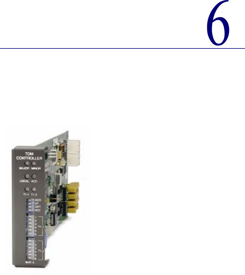

6-2 Compact T1 - Release 6.1
T1 Controller Card
Overview
Overview
The Compact T1 with the Dual T1 Controller Card offers a cost-effective, compact
solution that delivers a wide range of services from both wireline and wireless access
networks. The T1 Controller Card includes two T1 ports with integrated CSUs and a
built-in 1/0 cross-connect matrix providing full, non-blocking connectivity between the
T1 Controller Card and any of the six service card slots. The total T1 capacity can be
increased to 18 network access trunks or drop-and-insert user connections by adding a
full complement of Quad T1 Service Cards.
The Compact T1 offers a modular design that includes the T1 Controller Card
(required) and an array of available service cards. This flexibility allows the Compact
T1 to function in a variety of applications, including:
l1 to 18 T1 multi-service digital cross-connect system
l48 FXS/FXO/DPT channel bank
l24 FXS Voice over IP (VoIP) Customer Media Gateway (CMG)
l40 ISDN BRI shelf
l6 Ethernet IP Router/WAN nest
l2 to 12 V.35 or synchronous RS-232 port drop-and-insert CSU/DSU
l1 to 24 OCU-DP digital data service (DDS) delivery device
The modular Compact T1 platform also allows service providers to scale across service
types, network architectures, and bandwidth requirements to fit a dynamic service
delivery environment. Service cards provide the physical, electrical, and logical
connections for either customer service demarcations or network access. Any service
card can be placed in any service card slot. In addition, the (CMG) Service Card
enables the Compact T1 to provide a cost-effective migration path to packet-based
softswitching infrastructures using the MGCP protocol for both existing TDM-based
infrastructures and Greenfield VoIP applications.
The T1 Controller Card has several local and remote management options available.
The card can be configured and managed locally using the front-panel DIP switches or
the Command Line Interface (CLI). Front-panel LEDs quickly communicate alarm
and T1 line status, as well as mode of operation. Remote management is accomplished
directly either over an in-band DS0 management channel or via a separate SNMP
Ethernet connection.

Compact T1 - Release 6.1 6-3
T1 Controller Card
Features
Features
lAllows any service connection or network access line to be deployed in any slot
lProvides integrated 18 T1 port digital cross-connect for service grooming and
restoration
lSupplies integrated dual T1 CSU/DSUs and SNMP management on the
Controller
lSupport for VoIP services through the Customer Media Gateway (CMG) Service
Card (Note: CMG configuration assumes 5 CMG + 1 QT1, 24 channels per CMG
Card using G.711 @ 20 ms and 48 channels per CMG Card using over
subscription)
lEnables remote SNMP and Telnet provisioning, monitoring, and testing of
services and network conditions
lD4 PLAR to loop start conversion

6-4 Compact T1 - Release 6.1
T1 Controller Card
Technical Specifications
Technical Specifications
Product Includes
l18 T1 port built-in, non-blocking 1/0 Digital Cross-connect System
lRobbed-bit (voice) and clear channel (data) signaling on the same T1
lTR-08 signaling configured as either AB, BB, A or B
lIntegral dual T1 ports that support drop-and-insert applications
lT1.231 performance monitoring statistics: Ninety-six 15 minute segments
(24 hour period)
lPerformance Report Messages
lPBX trunk signaling, E&M to loop start and ground start conversion
lAnalog voice signaling, CLASS features such as Call Waiting, Call Forwarding,
Calling Party Disconnect and DNIS/DID
lFront-panel LED indicators for T1 status, major and minor alarms, remote/local
management mode, and Alarm Cut-Off status
lController support for IP router card code download through its Ethernet
management port
lConfigurations automatically stored in non-volatile memory
lD4 PLAR to loop start conversion
lSNMP agent, supporting MIB objects:
Advanced Features
lRADIUS Login Authentication
lSyslog
lNTP
- RFC 1213 (MIB-II) - RFC 2493
- RFC 1659 (V.35) - RFC 2494 (DS0-MIB)
- RFC 1907 (SNMPv2-MIB) - RFC 2495 (DS1-MIB)
- RFC 2011 (IP-MIB) - RFC 2571 (SNMP)
- RFC 2233 (IF-MIB)

Compact T1 - Release 6.1 6-5
T1 Controller Card
Technical Specifications
Management
lLocal
- Simple setup using front panel DIP switches for channel bank applications
- RS-232 craft port interface drives up to 50 ft. (15.24 m) cable, and provides a
Command Line Interface (CLI) using ASCII terminal or PC with terminal
emulation software, modem using XMODEM or PPP sessions
lRemote
- 10Base-T Ethernet management port provides
• Local IP management connectivity
• RJ-45 connector mounted on rear panel of chassis
• 10Base-T link LED status indicator
• IP management over a dedicated DS0 bearer channel
lIntegrated TFTP client for remote download of controller software upgrades
lCLI offers three levels of password controlled security
Network T1 Interface
lSelectable single or dual T1 ports operating at 1.544 Mbps ±50 bps
lExpansion to 18 T1s in a single chassis using Quad T1 Service cards
lSF (D4) and ESF framing
lAMI or B8ZS line coding
lShort or long-haul loop settings
lIntegrated CSU function
lLine build out (DSX-1): 655 feet
lReceive sensitive (DS1): 0 to -22.5 dB
lJitter and wander ITU-T B.824 (3/93)
lChannel status LEDs
lTwo RJ-48C connectors on rear panel of chassis
lSolid-state (fuseless) overvoltage and overcurrent T1 line protection meets
Telcordia GR-1089-CORE intra-building lightning/power cross limits
lCAS signaling options

6-6 Compact T1 - Release 6.1
T1 Controller Card
Technical Specifications
Service Interfaces Supported
lIP Router card (supports up to 24 WAN connections per card)
lCustomer Media Gateway (CMG) Service card (to support VoIP)
lFXO/DPT 8-channel Voice Service card
lFXS 8-channel Voice Service card
lISDN BRI 2, 4 and 8-channel Service cards
lDual V.35 and Dual V.35/V.54 Service cards
lQuad T1 Network Access/Drop-and-Insert Service card
lOCU-DP Single and 4 port Service cards
Network Standards
lAT&T Pub 54016, TR 62411
lANSI T1-403, T1.102, T1.231
Clocking
lLoop-timed from any T1
lRevertive clock switching provides automatic backup to secondary T1 should the
primary T1 fail
lOperates as a Stratum 4E device
Alarms
lOne major and one minor alarm output
lOne alarm input
lAlarm contacts accessible from external alarm connector
lAll alarms are logged in an event log
lLoss of AC power triggers minor alarm
lGenerates SNMP traps for alarming (MIB objects)

Compact T1 - Release 6.1 6-7
T1 Controller Card
Technical Specifications
Testing and Diagnostics
lStandard T1 line and payload loopbacks
lT1.231 performance history
Power Consumption
l4 W maximum
Regulatory Approvals
USA
lUL60950
lFCC Part 15, Class A
lFCC Part 68
lNEBS Level 3 certified
GR-63-CORE, GR-1089-CORE
Canada
lCSA C22.2 No. 60950-00
lICES-003, Class A
lCS-03
Physical
lDimensions: 3.5 in. (H) x 1 in. (W) x 11.25 in. (D)
8.9 cm (H) x 2.5 cm (W) x 28.6 cm (D)
lWeight: 5.7 oz. (.16 kg)
For information on Compact T1 Environment required, see Installation Environment
on page 2-2.

6-8 Compact T1 - Release 6.1
T1 Controller Card
Configuration
Configuration
Options on the Controller card are set by the DIP switches or the Command Line
Interface (CLI).
NOTE: The default IP address for the Controller is 10.0.0.10.
CLI Commands
The following commands are used to configure the Controller card. For detailed
information on these commands, see Chapter 5, CLI Commands.
l connect
Creates two-way connections between channels
l disconnect
Removes a connection created by the connect command
l set clock
Sets the primary and secondary transmit clock
l set date
Sets the date for the system
l set (ds1)
Sets up the DS1 interfaces (up, down, bpviolation, fdl, framing, id string,
lbo, line loopup, linecode, loopdetect, payload, threshold)
l set ipds0
Sets up the DS0 management channel (assign, disable, down, IP address, up)
l show (ds1)
Displays current settings for DS1 (circuit ID, up, down, framing, line
coding, clock source, line build out, loop code detection, loop back, fdl type)
l show ipds0
Displays the settings for the DS0 management channel
l status (ds1)
Displays the status of the DS1 (receive, transmit, loopback)
l status ipds0
Display the status of the DS0 management channel
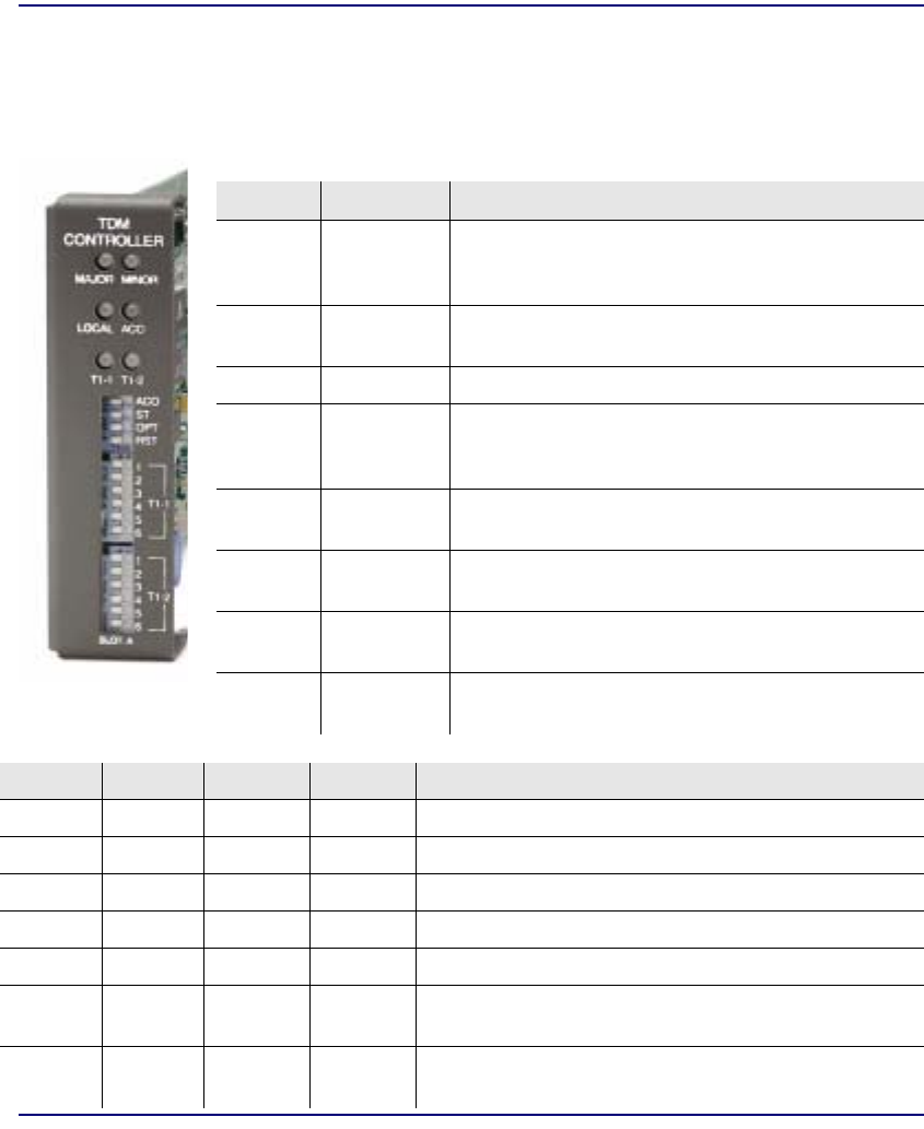
Compact T1 - Release 6.1 6-9
T1 Controller Card
Configuration
DIP Switch Settings
On the front of the TDM Controller card are DIP switches you can use to configure the
unit locally.
Switch Function Description
ACO Alarm Cut
Off 0 = Alarm contacts enabled (close when alarm occurs).
Default.
1 = Alarm contacts disabled (open).
ST Self Test 0 = Normal operation. Default.
1 = Perform Self Test.
OPT Spare
RST Reset 0 = User-configured operation. Default.
1 = Reset configuration to factory defaults, and reset CLI
password.
T1-1
T2-1
Line Coding 0 = B8ZS. Default.
1 = AMI
T1-2
T2-2
Line
Loopback 0 = Loopback off. Default.
1 = Loopback on
T1 3-4
T2 3-4
Framing 0 = ESF (Extended Superframe). Default.
1 = D4
T1 5 - 6
T2 5 - 6
Signaling
Switch 3 Switch 4 Switch 5 Switch 6 Setting
0 1 1 1 TR-08 A-Shelf with FDL, 16-bit Alarm frame
1 0 0 0 TR-08 A-Shelf with FDL, 13-bit Alarm frame
1 0 0 1 TR-08 A-Shelf with FDL disabled
1 0 1 0 TR-08 B-Shelf
0 0 0 0 Loop Start/Ground Start. Default.
0 0 0 1 E&M Immediate Start with ringback. (used for D3 PLAR
and DPT)
0 0 1 0 E&M Immediate Start with ringback and Calling Party
Disconnect (CPD)
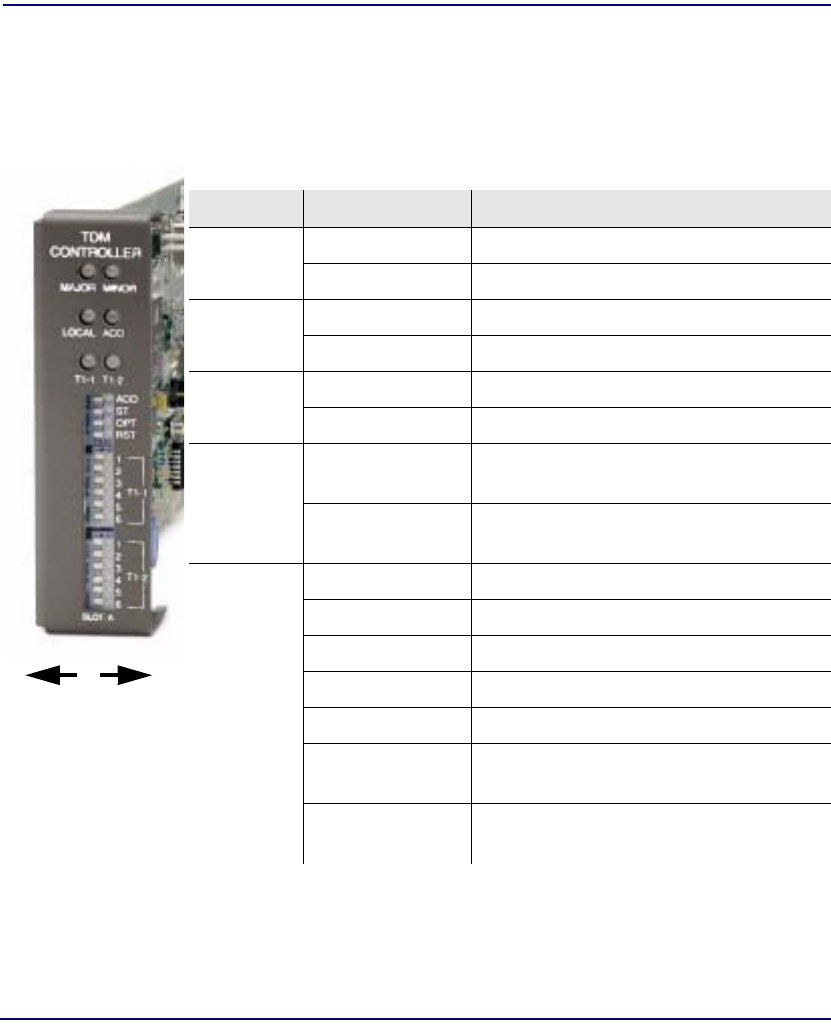
6-10 Compact T1 - Release 6.1
T1 Controller Card
LEDs
LEDs
The T1 Controller has a set of six LEDs you can use to troubleshoot your Compact T1.
The table below describes each LED.
LED State Description
MAJOR Off No major alarms present
Red Major alarm present
MINOR Off No minor alarms present
Yellow Minor alarms present
LOCAL Off Remote mode (DIP switches disabled)
Green Local mode (DIP switches enabled)
ACO Off Normal mode. No alarms are being
suppressed.
Yellow Alarm cutoff active. One or more active
alarms suppressed.
T1-1 and
T1-2 Off Off line
Green Normal
Red Loss of Signal (LOS) detected
Yellow Bipolar Violation (BPV) detected
Flashing Green Loopback active
Flashing Red Loss of Frame (LOF) or Alarm Indication
Signal (AIS) detected
Flashing Yellow Yellow alarm (Remote Alarm Indication)
detected.
0 (Off) 1 (On)
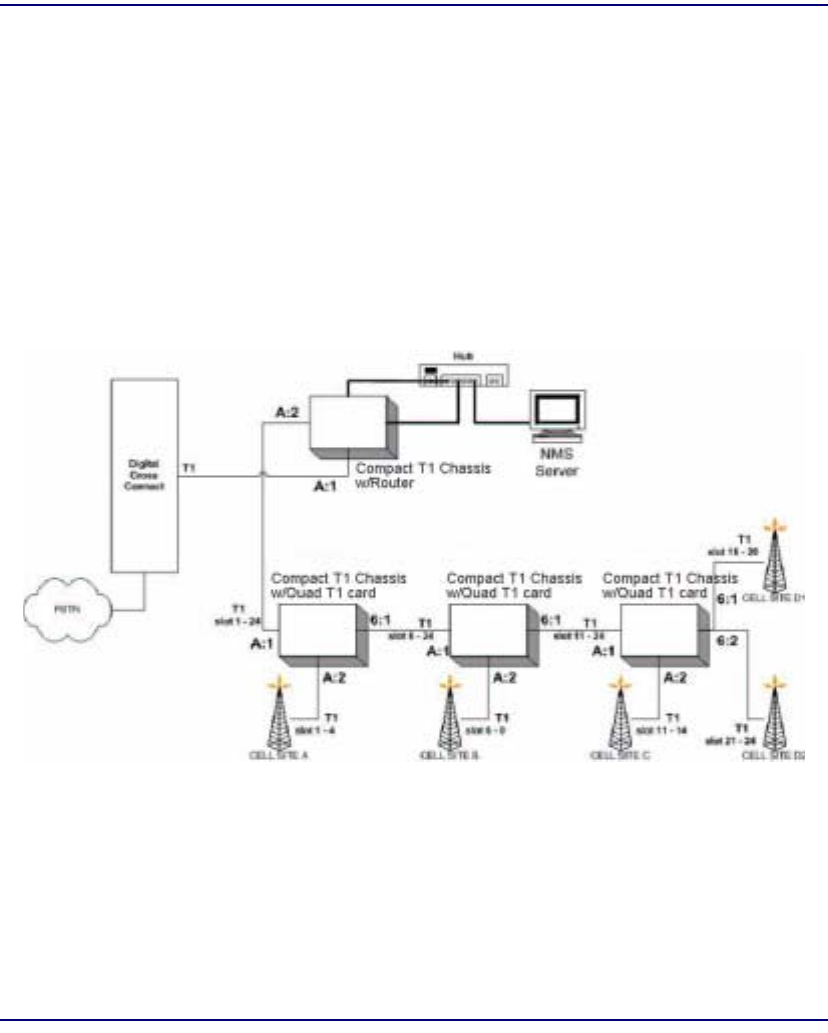
Compact T1 - Release 6.1 6-11
T1 Controller Card
DS0 Management (IP over DS0)
DS0 Management (IP over DS0)
The DS0 Management Channel provides SNMP management and remote access. The
IPDS0 feature allows for full Transmission Control Protocol/Internet Protocol
(TCP/IP) connectivity to remote Compact T1 and can be used for Simple Network
Management Protocol (SNMP) trap reporting and configuration, Trivial File Transfer
Protocol (TFTP) upgrades of Controllers and Service cards, and remote telnet access.

6-12 Compact T1 - Release 6.1
T1 Controller Card
TR-08 Mode 1
TR-08 Mode 1
The Compact T1 TR-08 will provide Mode 1 non-concentrated integrated service to the
Compact T1 platform. The TR-08/SLC-96 interface will allow a direct T1 physical
connection to a TR-08 capable digital switch, eliminating the need for an exchange
office end platform.
Each TR-08 provisioned T1 will handle the signaling throughput for 24 DS0 voice
channels. With T1-1 provisioned as an A shelf and T1-2 provisioned as a B shelf, the
Compact T1 will provide 48 DS0 voice channels with alarm reporting capability for
both shelves.
The TR-08 options can be provisioned either through CLI or controller front panel DIP
switches. When a T1 is provisioned to be TR-08, it’s respective set of service card slots
(T1-1 slots 1-3, T1-2 slots 4-6) will be nailed-up to the T1’s DS0s per TR-08 Mode 1.
Each T1 can be configured to be an A shelf or B shelf. The A shelf will carry alarm
information over FDL for the A and B shelf cards. The following combinations can be
set up:
lSingle A shelf
lTwo A shelves
lA and B shelf
lTR-08 provisioned T1 and a ESF provisioned T1
The A shelf can be set for FDL or no FDL and either alarm frame format 13 or 16 can
be selected. This selection can be done either by CLI (see set (ds1) in Chapter 5) or for
DIP switch settings (see DIP Switch Settings on page 6-9).
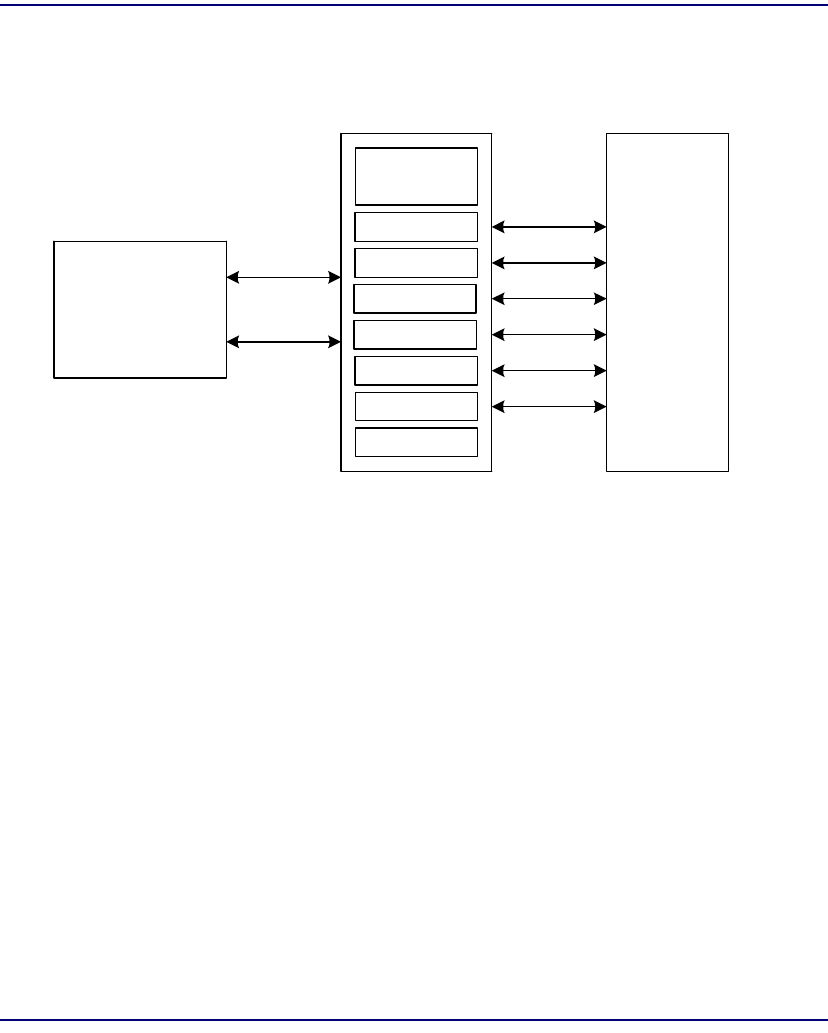
Compact T1 - Release 6.1 6-13
T1 Controller Card
TR-08 Mode 1
Compact T1 TR-08 Configuration
Digital
Switch
TDM Controller
Linecard
Linecard
Linecard
Linecard
Linecard
Linecard
Power Supply
T1-1
T1-2
Customer
Premise
Equipment
(CPE)
Adit 600 TDM TR-08
Compact T1 TR-08

6-14 Compact T1 - Release 6.1
T1 Controller Card
TR-08 Mode 1
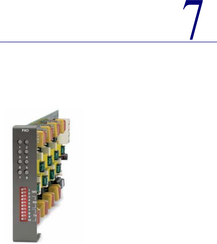

7-2 Compact T1 - Release 6.1
FXO Voice Card
Overview
Overview
The FXO Voice Service card provides high-density provisioning of reliable Foreign
Exchange Office (FXO) or Direct Inward Dialing (DID) telephone services. Eight FXO
or Dial Pulse Terminate (DPT) telephone line channels can be deployed on each FXO
Service card. These cards can be inserted into any slot of the Compact T1 six-slot
chassis, and up to 96 lines in two side-by-side chassis occupying just two rack units of
space.
The FXO function sinks battery current and detects ringing voltage originating from
the central office or PBX line, enabling the transport of dial tone and calling features
to remote locations. When configured as a DPT interface, the channels sink and detect
forward and reverse line current, emulating the functions of a central office DID line.
DID service provides the necessary dialed digits to ring a telephone extension directly
through a PBX, without requiring attendant intervention. DPT and FXO functions are
also used with Automatic Call Distributor (ACD), voice mail, and Computer
Telephony Integration (CTI) applications.
A unique range of software-controlled signaling capabilities connects virtually any
type of 20 wire battery-sink telephone line service. Supported features include caller
ID, calling party disconnect, distinctive ringing, ground start, and E&M signaling
conversion. Automatic impedance balancing provides echo-free service connections
across a wide range of customer equipment and line conditions. V.90 transmission
ensures optimal dial-up modem performance.
As a component of the Compact T1 platform, the FX0 Service card as several local and
remote management options available through the Compact T1 Controller. The card
can be locally configured and managed using the front-panel DIP switches or the
Command Line Interface (CLI). Front-panel LEDs indicate call progress and channel
status.

Compact T1 - Release 6.1 7-3
FXO Voice Card
Features
Features
lDelivers FXO or DID telephone services from T1 access circuits
lSupports CLASS services including Caller ID, Calling Party Disconnect and
Distinctive Ringing
lProvides up to 48 FXO or DPT voice lines in one chassis, or up to 96 lines in two
side-by-side Compact T1s occupying just two rack units of equipment space (19
inch rack)
lComplies with NEBS Level 3 standards for loop range and ringing protection for
end office and customer premises
lOffers fuseless overvoltage and overcurrent protection to minimize service calls
from lightning and power cross incidents
Technical Specifications
Controller Software Required
T1 Controller
lRelease 1.2.2 or higher is required

7-4 Compact T1 - Release 6.1
FXO Voice Card
Technical Specifications
FXO Transmission Performance
lReturn Loss: ERL > 26 dB, SRL > 18 dB with respect to 900Ω + 2.16µF
lTranshybrid Loss: ERL > 26 dB, SRL > 18 dB with respect to 900Ω + 2.16µF
lIdle Noise: A/D < 16 dBrnC0, D/A, 12 dBrnC0
lCrosstalk Coupling: < 70 dB at 0 dBrn0
lSignal/Distortion: > 35 dB with 1004 Hz, 0 dBm0 input
lOverload: +3.0 dBm/900Ω
lFrequency Response: +0.3 dB -1.0 dB from 300 to 3400 Hz
lEncoding: µ-law 255 for U.S. and Canada as defined in CCITT G.711 and G.712
lTerminating Impedance: 900Ω + 2.16µF
lTransmit Gain/Loss: +7 to -9 dB, switch selectable per card
lReceive Gain/Loss: +7 to -9 dB, switch selectable per card
lModem Support: Full compatibility with V.90 modems
FXO Signaling Performance
lDC Loop Range: > 1600Ω loop or ground start
lRinger Equivalency Number (REN): 0.4B (AC)
lRinging Voltage Detection: detects Class A ringing follows distinctive ringing
lFXO DC Resistance: 100Ω
lMaximum DC: 150 mA
lOvervoltage: UL 1950, FCC Part 68 lightning protection
lOvercurrent: 600 V rms, 60 Amps
lProtection: solid-state (fuseless) overvoltage and over current protection
lTermination Type: FXO loop start or ground start, switch selectable per card or
via management interface per channel
lSignaling Selection: DPT functionality enabled/disabled on all 8 channels
lAddress Signaling: DTMF or dial pulse
lCalling Party Disconnect: detects and forwards current interruption to disconnect
answering devices and modems

Compact T1 - Release 6.1 7-5
FXO Voice Card
Technical Specifications
Regulatory Approvals
USA
lUL60950
lFCC Part 15, Class A
lFCC Part 68
lNEBS Level 3 certified for type 2 and 4 equipment
GR-63-CORE, GR-1089-CORE
Canada
lCSA C22.2 No. 60950-00
lICES-003, Class A
lCS-03
Physical
lConnections made on RJ21-X telco connector rear panel
lDimensions: 3.5 in. (H) x 0.75 in. (W) x 11.25 in. (D)
8.9 cm (H) x 1.9 cm (W) x 28.6 cm (D)
lWeight: 9.1 oz. (.26 kg)
For information on Compact T1 Environment required, see Installation Environment
on page 2-2.

7-6 Compact T1 - Release 6.1
FXO Voice Card
Card Configuration
Card Configuration
The FXO voice card can be configured, using DIP switches on the card, to support
either FXO loop start or FXO ground start signaling, with various transmit and receive
attenuation options.
Note that the attenuation settings you configure via DIP switches apply to all eight
channels on a card. If you want different attenuation options for individual channels,
use the Command Line Interface to configure your FXO channels.
CLI Commands
The following commands are used to configure the FXO card. For detailed information
on these commands, see Chapter 5, CLI Commands.
l connect
Creates two-way connections between channels
l disconnect
Removes a connection created by the connect command
l set (fxo)
To setup the voice channels parameters (rx gain, signal, tx gain)
l show (fxo)
Displays the settings (type, signaling, RxGain, TxGain) for the FXO
l status (ds0)
Displays the status (AB bits received, AB bits transmitted, signal, trunk
processing) of the DS0s (AB Bit Monitoring)
l status (fxo)
Displays the status (AB bits received, AB bits transmitted, signal, T1
activity, trunk processing) of the specified FXO (AB Bit Monitoring)
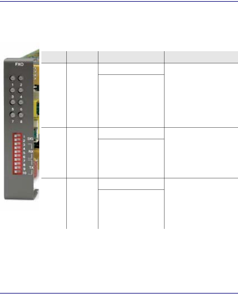
Compact T1 - Release 6.1 7-7
FXO Voice Card
Card Configuration
DIP Switch Settings
Each FXO card contains ten DIP switches that can be used to select signaling options
for all eight channels.
Switch Function Description Note
1-2 Signal
Type 1 2
0 0 = FXO Loop Start
1 0 = FXO Ground Start
0 1 = DPT (use with
E&M setting on T1)
1 1 = FXO Loop Start
with Calling Party
Disconnect
3-6 Receive
Gain/Loss 3 4 5 6 These settings allow for
receive gain and losses of -9,
-7, -6, -5, -4, -3, -2, 0, 2, 3, 4,
5, 6, and 7.
+9 (1110) is not available.
0 0 0 0 = 0 dB
0 0 0 1 = -9 dB
0 0 1 0 = +2 dB
0 1 0 0 = +3 dB
1 0 0 0 = +4 dB
7-10 Transmit
Gain/Loss 7 8 9 10 These settings allow for
transmit gain and losses of -
9, -7, -6, -5, -4, -3, -2, 0, 2, 3,
4, 5, 6, and 7.
+9 (1110) is not available.
0 0 0 0 = 0 dB
0 0 0 1 = -9 dB
0 0 1 0 = +2 dB
0 1 0 0 = +3 dB
1 0 0 0 = +4 dB
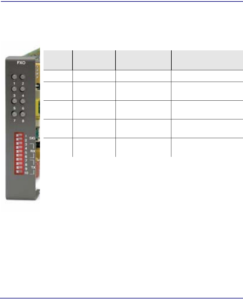
7-8 Compact T1 - Release 6.1
FXO Voice Card
LEDs
LEDs
Each FXO port on a card has its own LED, described in the table below.
State Loop Start
Meaning Ground Start
Meaning Dial Pulse Termination
Meaning
Off N/A Idle (tip open) Idle (loop open)
Green Idle Tip ground
(incoming seizure) Incoming seizure
Red N/A Ring ground
(outgoing seizure) Loop closure (outgoing
seizure)
Yellow Call in progress Call in progress Call in progress (reverse
battery)
Flashing
green Ringing Ringing N/A

Compact T1 - Release 6.1 7-9
FXO Voice Card
Channel Associated Signaling (CAS) Conversions
Channel Associated Signaling (CAS)
Conversions
Cross-connects are done at a DS0 level. The following rules need to be kept in mind
while performing cross-connects for a FXO voice card.
DPT = Dial Pulse Termination
EMDW = E&M Delayed Wink start
EMI = E&M Immediate start
EMICPD = E&M Immediate Start with Calling Party Disconnect
EMW = E&M Wink start
GS = Ground Start
GSRB = Ground Start with Reverse Battery
LS = Loop Start
LSCPD = Loop Start Calling Party Disconnect
LSRB = Loop Start with Reverse Battery
VoIP = Voice over IP (CMG only)
DS0 FXO Analog
LS GS DPT LSCPD
VoIP Port
LS N N N N
T1 DS0
LS YN N Y
GS N Y N N
EMDW N N N N
EMI N N Y N
EMICPD N N N N
EMW N N N N

7-10 Compact T1 - Release 6.1
FXO Voice Card
Channel Associated Signaling (CAS) Conversions


8-2 Compact T1 - Release 6.1
FXS Voice Card
Overview
Overview
The FXS Voice Service card provides high-density provisioning of cost-effective
telephone services. Eight Foreign Exchange Station (FXS) telephone line channels can
be deployed on each FXS Voice Service card. These cards can be inserted into any card
slot of the six-slot Compact T1. This allows the provisioning of up to 48 FXS lines in
a single chassis and up to 96 lines in two side-by-side units occupying just two rack
units of space.
A unique range of software-controlled signaling capabilities connects virtually any
type of 2-wire battery-feed telephone line service. FXS loop start or ground start
interfaces provide either outside (external) phone lines or on-premises (internal)
business line services. Supported features include caller ID, calling party disconnect,
distinctive ringing, three-way calling, and E&M signaling conversion. Automatic
impedance balancing provides echo-free service connections for a wide range of
customer equipment and line conditions. V.90 transmission ensures optimal dial-up
modern performance.
As a component of the Compact T1 platform, the FXS service card has several local
and remote management options available through the Controller. The card can be
locally configured and managed using the front-panel DIP switches or the Command
Line Interface (CLI). Front-panel LEDs quickly communicate call progress and
channel status.

Compact T1 - Release 6.1 8-3
FXS Voice Card
Features
Features
lSupports CLASS services including Caller ID, Calling Party Disconnect and
Distinctive Ringing
lProvides up to 48 FXS voice lines in one chassis or up to 96 lines in two side-by-
side units occupying just two rack units of equipment space (19-inch rack)
lComplies with NEBS Level 3 standards for loop range and ringing protection for
end office and customer premises
lOffers fuseless overvoltage and overcurrent protection to minimize service calls
from lightning and power cross incidents
lMinimizes power consumption for high-density service delivery with automatic
battery voltage switching
lSelectable impedence and CODEC types

8-4 Compact T1 - Release 6.1
FXS Voice Card
Technical Specifications
Technical Specifications
Controller Software Required
T1 Controller
lRelease 1.50 or higher is required for the FXS 5G card
FXS Transmission Performance
lReturn Loss: ERL > 28 dB, SRL > 20 dB with respect to 900Ω + 2.16µF
lTranshybrid Loss: ERL > 28 dB, SRL > 20 dB with respect to 900Ω + 2.16µF
lIdle Noise: A/D < 15 dBrnC0, D/A, < 10 dBrnC0
lCrosstalk Coupling: < 80 dBm0 at 0 dBrnC0
lSignal/Distortion: > 45 dB with 1004 Hz, 0 dBm0 input
lTerminating Impedance: 900Ω + 2.16µF
lTranshybrid Impedance: automatic
lTransmit Gain/Loss: +6 to -12 in .25 increments, switch selectable per card or
management selectable per channel
lReceive Gain/Loss: +6 to -12 in .25 increments, switch selectable per card or
management selectable per channel
lOverload: +3.0 dBm/90
lFrequency Response: +0 dB -1.0 dB from 300 to 3400 Hz
lLongitudinal Balance: >63 dB per IEEE 455 and FCC Part 68
lModem Support: Full compatibility with V.90 modems

Compact T1 - Release 6.1 8-5
FXS Voice Card
Technical Specifications
FXS Signaling Performance
lDC Loop Range: 1000Ω standard, 1600Ω extended
lLoop Feed: Nominal -48 VDC with 31mA current limit for long loops, -36 VDC
@ 27mA for short loops with automatic battery switching
lOff-Hook Detection: Detects tip or ring currents > 6mA
lRing Ground: Detects ring ground currents > 8mA
lRinging Voltage: All-channel simultaneous ringing power, 85 V rms, 20 Hz
lMaximum Ringers: 5 REN, FCC Class B ringers
lInternal Ringing Cadence: Ringing cadence is 2 seconds on, 4 seconds off for
E&M wink start conversion modes
lControl Technique: Solid-state with no mechanical relays
lOvervoltage: UL 1950, FCC Part 68 lightning protection
lOvercurrent: 600 V rms, 60 Amps
lSupports CLASS features such as calling party ID, three-way calling, and
distinctive ringing
lCalling Party Disconnect: Calling party (forward) disconnect provides 2 second
current interruption to disconnect answering devices and modems - requires
E&M signaling service on the T1
lFXS Signaling: FXS loop start or FXS ground start with LS/GS selection per
channel
lFXSDN Signaling: E&M immediate or wink start to either loop start or ground
start conversion with ringback tone for carrier services such as Megacom®,
Flexpath®, DSS®, VPN®, VNET®, etc. Wink delay for advanced ANI/DNIS 800
number services
lRinger Equivalency Number (REN): 0.0 by definition

8-6 Compact T1 - Release 6.1
FXS Voice Card
Technical Specifications
Regulatory Approvals
USA
lUL60950
lFCC Part 15, Class A
lNEBS Level 3 certified for type 2 and 4 equipment
GR-63-CORE, GR-1089-CORE
Canada
lCSA C22.2 No. 60950-00
lICES-003, Class A
Physical
lConnections made on RJ-21X telco connector rear panel
lDimensions: 3.5 in. (H) x 0.75 in. (W) x 11.25 in. (D)
8.9 cm (H) x 1.9 cm (W) x 28.6 cm (D)
lWeight: 5.8 oz. (.16 kg)
For information on Environment required, see Installation Environment on page 2- 2.

Compact T1 - Release 6.1 8-7
FXS Voice Card
Card Configuration
Card Configuration
The FXS voice card can be configured, using DIP switches on the card, to support
either FXS loopstart or FXS groundstart signaling, with various transmit and receive
attenuation options.
Note that the attenuation settings configured via DIP switches apply to all eight
channels. For different attenuation options for individual channels, use the CLI.
CLI Commands
The following commands are used to configure the FXS cards. For detailed information
on these commands, see Chapter 5, CLI Commands.
l connect
Creates two-way connections between channels
l disconnect
Removes a connection created by the connect command
l set (fxs5G)
To setup the voice channels parameters of a FXS 5G card (rx gain, signal, tx
gain, impedance and wink time)
l show (fxs5G)
Displays the settings (type, signaling, rx gain, tx gain, impedance, wink
time) for the FXS 5G
l show impedance
Displays the impedance settings for FXS 5G cards
l status (fxs5G)
Displays the status (AB bits received, AB bits transmitted, signal, T1
activity, trunk processing) of the specified FXS (AB Bit Monitoring)
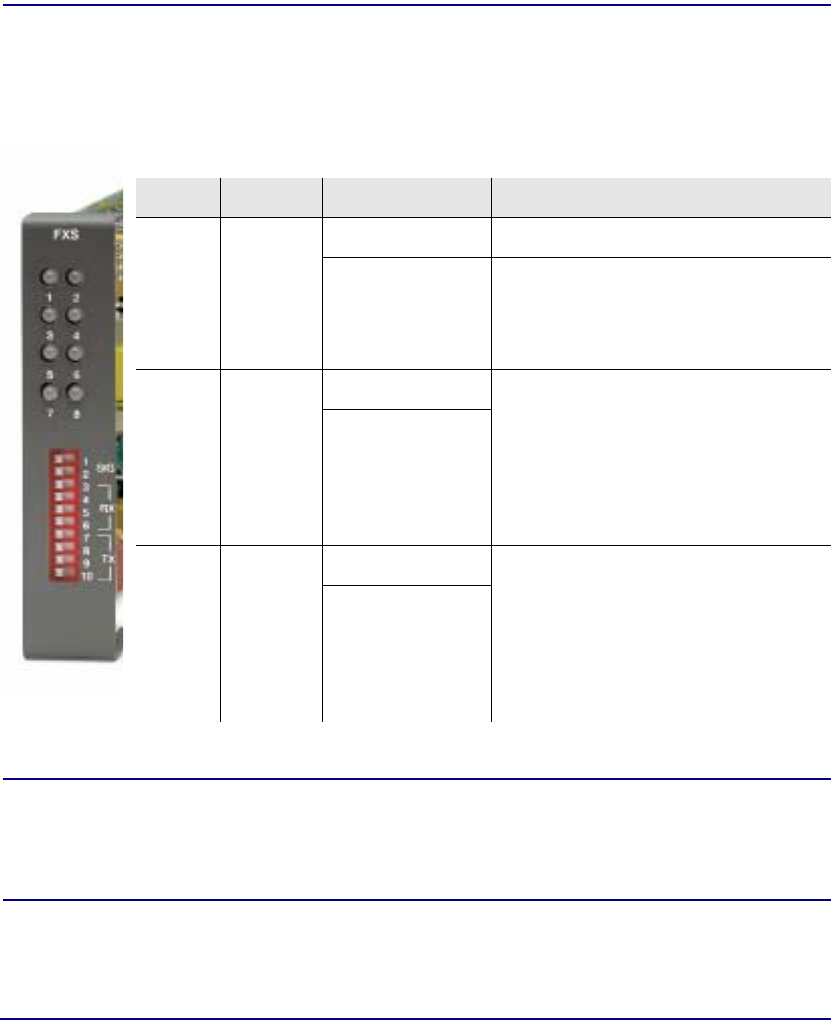
8-8 Compact T1 - Release 6.1
FXS Voice Card
Card Configuration
DIP Switch Settings
Each FXS card contains ten DIP switches that can be used to select signaling options
for all eight channels.
NOTE: The FXS channels default to a short loop setting
(up to 1.6 miles for 26 AWG, and 2.6 miles for 24 AWG). To set an FXS
channel to have a long loop setting, see set (fxs5G) command in Chapter 5,
CLI Commands.
Switch Function Description Note
1-2 Signal
Type 1 2
0 0 = FXS Loop
Start
1 0 = FXS Ground
Start
3-6 Receive
Gain/
Loss
3 4 5 6 These settings allow for receive gain
and losses of -9, -7, -6, -5,
-4, -3, -2, 0, 2, 3, 4, 5 and 6.
0 0 0 0 = 0 dB
0 0 0 1 = -9 dB
0 0 1 0 = +2 dB
0 1 0 0 = +3 dB
1 0 0 0 = +4 dB
7-10 Transmit
Gain/
Loss
7 8 9 10 These settings allow for transmit gain
and losses of -9, -7, -6, -5, -4, -3, -2, 0,
2, 3, 4, 5 and 6.
0 0 0 0 = 0 dB
0 0 0 1 = -9 dB
0 0 1 0 = +2 dB
0 1 0 0 = +3 dB
1 0 0 0 = +4 dB
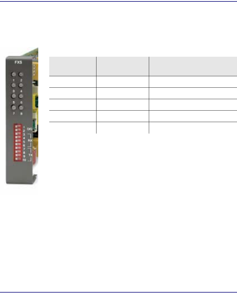
Compact T1 - Release 6.1 8-9
FXS Voice Card
LEDs
LEDs
Each FXS port has a corresponding LED, described in the table below. This chart
applies to all the FXS service cards.
State Loop Start
Meaning Ground Start Meaning
Off N/A Idle (tip open)
Green Idle Tip ground (incoming seizure)
Red N/A Ring ground (outgoing seizure)
Yellow Call in progress Call in progress
Flashing green Ringing Ringing

8-10 Compact T1 - Release 6.1
FXS Voice Card
Channel Associated Signaling (CAS) Conversions
Channel Associated Signaling (CAS)
Conversions
Cross-connects are done at a DS0 level. The following rules need to be kept in mind
while performing cross-connects for an FXS voice card. The following chart does not
apply to the FXS INTL card, which only carries R2 signaling.
EMDW = E&M Delayed Wink start
EMI = E&M Immediate start
EMICPD = E&M Immediate Start with Calling Party Disconnect
EMW = E&M Wink start
GS = Ground Start
GSW = Ground Start Wink
GSRB = Ground Start with Reverse Battery
LS = Loop Start
LSRB = Loop Start with Reverse Battery
TR8LSGS = TR-08 Loop Start/Ground Start
VoIP = Voice over IP (CMG only)
DS0 FXS Analog
LS/LSRB GS/GSRB GSW
VoIP Port
LS Y N N
T1 DS0
LS YYN
GS Y Y N
EMDW Y Y N
EMI Y N N
EMICPD Y Y N
EMW Y Y N
TR8LSGS Y Y N
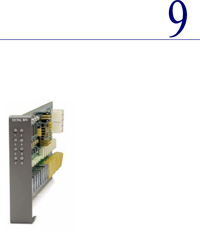

9-2 Compact T1 - Release 6.1
ISDN BRI Card
Overview
Overview
The ISDN BRI Service Cards enable service providers and enterprises to deploy high-
density, standards-based, ISDN Basic Rate Interface (BRI) services over one or more
T1 or DSL access lines using TDM or ATM transport. ISDN voice, data, and real-time
video applications may be cost effectively deployed as part of any integrated
broadband service delivery.
ISDN BRI
BRI provides an end-to-end digital connection for customers with voice, data and video
needs. BRI has 2 Bearer (B) channels at 64 Kbps for voice or data and 1 Data or Delta
(D) channel at 16 Kbps for signal and control. With some ISDN BRI devices, the two
B-channels can be aggregated together for 128 Kbps capacity.
3-DS0 BRITE Mode
The ISDN BRI Card supports the 3-DS0 BRITE mode of operation. In this mode, three
DS0 channels support a BRI channel, providing eight BRI per T1. The BRI channel
consists of two B and a D channel (2B+D) which is also transported in a full DS0. The
D-channel supports the Embedded Operations Channel (EOC) and is used to pass
signaling and other management information, such as loopback commands.
The following is an example of how a Compact T1 with a ISDN BRI card can function
as a Line Unit Network Termination (LUNT) with central office applications, and a
Line Unit Line Termination (LULT) with subscriber lines.

Compact T1 - Release 6.1 9-3
ISDN BRI Card
Features
Features
lEnables carriers to economically bundle ISDN with all other services at 64 Kbps
or 128 Kbps over T1 access lines
lConfigurable as either Line Unit Line Terminal (LULT) for interfacing to ISDN
switch interfaces at the central office, or Line Unit Network Terminal (LUNT)
for customer premises deployment
lProvides direct NTU service demarcation for ISDN video conferencing, 128
Kbps dial-up Internet, point-of-sale terminals, and ISDN Centrex or telephone
applications
lEnables high service density with up to 40 ISDN BRI lines from 4 T1 lines in a
single Compact T1, or up to 80 ISDN BRI lines in two chassis occupying two
rack units of equipment space (19-inch rack)
lOffers solid-state fuseless protection for central office NEBS compliance and
customer premises FCC and UL safety requirements

9-4 Compact T1 - Release 6.1
ISDN BRI Card
Technical Specifications
Technical Specifications
Controller Software Required
T1 Controller
lRelease 1.2.2 or higher is required
Product Includes
lConfigurable as Line Unit Line Terminal (LULT) or Line Unit Network Terminal
(LUNT)
lWorks with all standard Carrier Serving Area (CSA) loops - maximum 18,000 ft.
range (#26 AWG copper)
lLine coding: 2
lLine Rate: 160 Kbps (80 kbaud)
lFront-panel multi-function LEDs provide out-of-Service, LOS/Self-test fail,
ES/SES detected, Sync, Loopback, and Normal indications
lInteroperable with other standards-based ISDN BRI equipment
lB1, B2, and 2B+D payload loopbacks supported
lMaximum bridged tap length is 2.5 kft. (762 m)
lRear-accessed U-interface connections
Management
lStandard ISDN SNMP MIB supported
Network Interface
l3 DS0 mode: Uses 3 contiguous DSO channels per ISDN BRI channel on T1

Compact T1 - Release 6.1 9-5
ISDN BRI Card
Technical Specifications
Network Standards
lTelcordia TR-NWT-000397 (1993)
lTelcordia TR-TSY-000821 (1991)
lTelcordia TR-TSY-000829 (1989)
lANSI T1.1992
lITU-T Q.920, Q.921
Clocking
lLoop timing derived from Channel 1 of ISDN BRI card or any Compact T1 T1
line
Testing & Diagnostics
lInitiates 2B+D, B1, or B2 loopbacks toward the BRI at the NT1
lPerforms self test at power up
l3 DSO mode: supports external loopback testing via EOC messages from the
switch
Product Supports
lTR-821 alarms
lTR-397/TR-829/TR-821 Generic Segmented Performance Monitoring
lTR-829 multi-EOC messages in 3 DS0 and 4:1 TDM modes
lMetallic DC test signature in Line Unit Network Terminal (LUNT) mode
Power
lMaximum power input: 6 W (8 port)
lSolid-state fuseless protection

9-6 Compact T1 - Release 6.1
ISDN BRI Card
Technical Specifications
Regulatory Approvals
USA
lUL60950
lFCC Part 15, Class A
lNEBS Level 3 certified for type 2 and 4 equipment
GR-63-CORE, GR-1089-CORE
Canada
lCSA C22.2 No. 60950-00
lICES-003, Class A
Physical
lDimensions: 3.5 in. (H) x 0.75 in. (W) x 11.25 in. (D)
8.9 cm (H) x 1.9 cm (W) x 28.6 cm (D)
lWeight: 6.9 oz. (.20 kg)
For information on Compact T1 Environment required, see Installation Environment,
on page 2-2.

Compact T1 - Release 6.1 9-7
ISDN BRI Card
Card Configuration
Card Configuration
BRI card options are set with the Command Line Interface (CLI). For additional
information on these commands, see Chapter 5, CLI Commands.
CLI Commands
l connect
Creates two-way connections between channels
l disconnect
Removes a connection created by the connect command
l set (bri)
Setup of ISDN ports (up/down, threshold, call reference value)
l set (bri) autoactivate
Set up the ISDN circuits when the FDL link cannot be used
l set (bri) mode
Set up ISDN cards mode of operation (3-DS0)
l set (bri) pmsync
Set up the BRI card source for performance monitoring synchronization
l set (ds0)
For cross-connect to ISDN, must be data type
l status (ds1)
Displays line status or performance statistics of a specific DS1
l set clock
Set the primary and secondary (clock1/clock2) master transmit clock source
l show (bri)
Displays BRI port configuration
l show clock
Displays actual clock source
l show (ds1)
Displays DS1 configuration
l status (bri)
Displays port status or performance statistics for the specified BRI
l status clock
Displays actual clock status and source
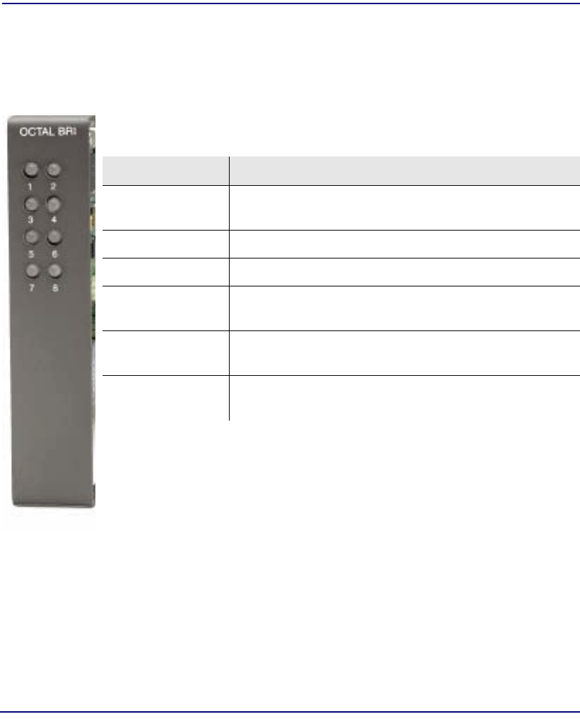
9-8 Compact T1 - Release 6.1
ISDN BRI Card
LEDs
LEDs
There is an LED for each ISDN BRI on a card. The function for each LED is listed
below:
State Description
Off Line U-interface is attempting synchronization, or BRI is
out of service.
Red Line alarm (LOS or self test failure)
Yellow ES or SES has occurred.
Flashing yellow Line U-interface is synchronized with customer equipment,
but is not passing customer data.
Flashing green Line U-interface is in external loopback toward the switch at
the unit.
Green Normal (Line U-interface is active and transparently passing
customer data.)
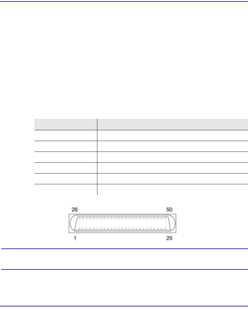
Compact T1 - Release 6.1 9-9
ISDN BRI Card
Connector Pinouts
Connector Pinouts
25-Pair Telco Connectors
Circuit connections are made at the 25-pair telco connectors. A standard 25-pair
telephone cable with RJ-21X wiring and a male D-type connector at the Compact T1
end is required.
Slot/Pair Designation
The following designations apply whether a Dual, Quad or Octal ISDN BRI Card
is placed in Slot 1 through 6. However, a Dual would only use the first 2 of the 8
pair, a Quad the first 4, and an Octal all 8. The following is the breakdown of
designated pairs to each Compact T1 slot.
NOTE: For the location of the 25-Pair Telco Connectors, on the back of
the Adit, see 25-Pair Telco Connectors, on page 3-9
SLOT 25-Pair Telco Connector
#1 #1 - 8 (first 8 pairs) on J1
#2 # 9 - 16 (next 8 pairs) on J1
#3 # 17 - 24 (next 8 pairs) on J1
#4 #1 - 8 (first 8 pairs) on J2
#5 # 9 - 16 (next 8 pairs) on J2
#6 # 17 - 24 (next 8 pairs) on J2

9-10 Compact T1 - Release 6.1
ISDN BRI Card
Connector Pinouts
25-Pair Telco Connector Pinouts
Pair Pin Location Function Color Code
1 26
1Tip Channel 1
Ring Channel 1 White
Blue
2 27
2Tip Channel 2
Ring Channel 2 White
Orange
328
3Tip Channel 3
Ring Channel 3 White
Green
429
4Tip Channel 4
Ring Channel 4 White
Brown
530
5Tip Channel 5
Ring Channel 5 White
Slate
631
6Tip Channel 6
Ring Channel 6 Red
Blue
732
7Tip Channel 7
Ring Channel 7 Red
Orange
833
8Tip Channel 8
Ring Channel 8 Red
Green
934
9Tip Channel 9
Ring Channel 9 Red
Brown
10 35
10 Tip Channel 10
Ring Channel 10 Red
Slate
11 36
11 Tip Channel 11
Ring Channel 11 Black
Blue
12 37
12 Tip Channel 12
Ring Channel 12 Black
Orange
13 38
13 Tip Channel 13
Ring Channel 13 Black
Green
14 39
14 Tip Channel 14
Ring Channel 14 Black
Brown
15 40
15 Tip Channel 15
Ring Channel 15 Black
Slate
16 41
16 Tip Channel 16
Ring Channel 16 Yellow
Blue
SLOT 1 on J1 or SLOT 4 on J2
SLOT 2 on J1 or SLOT 5 on J2

Compact T1 - Release 6.1 9-11
ISDN BRI Card
Connector Pinouts
Pair Pin Location Function Color Code
17 42
17 Tip Channel 17
Ring Channel 17 Yellow
Orange
18 43
18 Tip Channel 18
Ring Channel 18 Yellow
Green
19 44
19 Tip Channel 19
Ring Channel 19 Yellow
Brown
20 45
20 Tip Channel 20
Ring Channel 20 Yellow
Slate
21 46
21 Tip Channel 21
Ring Channel 21 Violet
Blue
22 47
22 Tip Channel 22
Ring Channel 22 Violet
Orange
23 48
23 Tip Channel 23
Ring Channel 23 Violet
Green
24 49
24 Tip Channel 24
Ring Channel 24 Violet
Brown
25 50
25 Reserved Violet
Slate
SLOT 3 on J1 or SLOT 6 on J2

9-12 Compact T1 - Release 6.1
ISDN BRI Card
Connector Pinouts
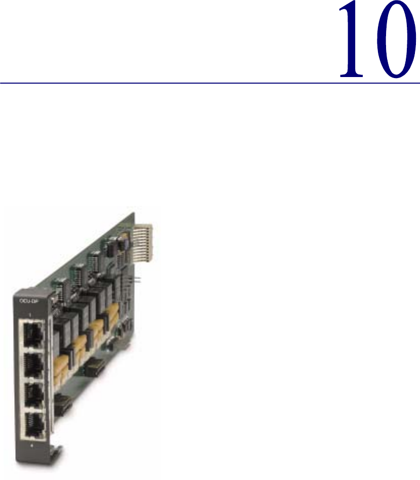

10-2 Compact T1 - Release 6.1
OCU-DP Card
Overview
Overview
The Single and Quad Port all-rate OCU-DP Service Cards provide electrical and
physical termination of the 4-wire Digital Data Service (DDS) that is traditionally used
to interconnect lower-speed serial synchronous Data Terminal Equipment (DTE)
devices such as routers, Frame Relay Access Devices (FRAD), or video conferencing
equipment. Now DDS can be integrated with DS0 voice, fractional T1 data, ISDN, and
IP services – over multiple T1s or DS3s. This enables service providers to deliver
transport for legacy enterprise data networking or Common Channel Signaling (CCS)
circuits commonly used in Signaling System 7 (SS7) telephone networks using one
card for all standard DDS types. Plus, it can be used as a replacement for low-density,
unmanaged D4 channel banks.
The OCU-DP Service Cards provide scalable, independently configurable,
synchronous data service rates from 2.4 Kbps to 64 Kbps, including Switched 56 Kbps
data rates. Up to eight OCU-DP cards can be inserted into any of the service card slots
of the Compact T1, providing up to 32 DDS connections. These cards enable industry
leading density and cost per port at Central Offices (COs) hub and collocations
(COLOs) and cell sites.
For example, the OCU-DP ports can be groomed and mapped into any of the DS1 or
DS3 ports of the Controller. The Compact T1's (3/1/0) digital cross-connect
functionality offers DS0 service grooming, T1 drop-and-insert, and voice access
integration not available in traditional multiplexers.
The OCU-DP Service Cards have several local and remote management options
available through the Controllers. Cards can be locally configured and managed using
the Command Line Interface (CLI). Remote management is accomplished directly over
either an in-band DS0 management channel or a separate SNMP network connection.
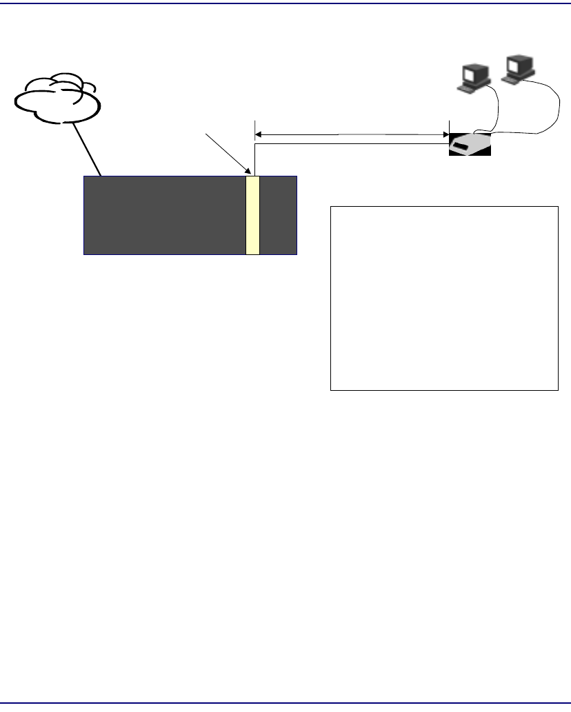
Compact T1 - Release 6.1 10-3
OCU-DP Card
Overview
Customer Premise Application
In this model, the carrier deploys the Compact T1 in conjunction with DDS DSU/CSUs
to provide standards-based DDS access for customer data terminal needs. In essence,
the Compact T1 integrates the DDS capabilities that were traditionally served by D4 or
DLC Remote Terminal equipment into a customer premise multi-service solution.
CAC Confidential
OCU DP
ADIT 600 2.4 - 72 KBPS
DSU/CSU
Local Loop: 4-wire DDS
Bipolar AMI, RZ
PSTN
T1 RS-232
or V.35
Line Rates
Primary Channel / Primary and Secondary
Only Channel
64 KBPS / 72 KBPS
56 KBPS / 72 KBPS
38.4 KBPS / 51.2 KBPS
19.2 KBPS / 25.6 KBPS
9.6 KBPS / 12.8 KBPS
4.8 KBPS / 6.4 KBPS
2.4 KBPS / 3.2 KBPS
DS0A data channel format
-45 dB maximum loop loss, all rates
Four RJ-48S 4-wire
keyed jacks
Primary Secondary
Compact T1
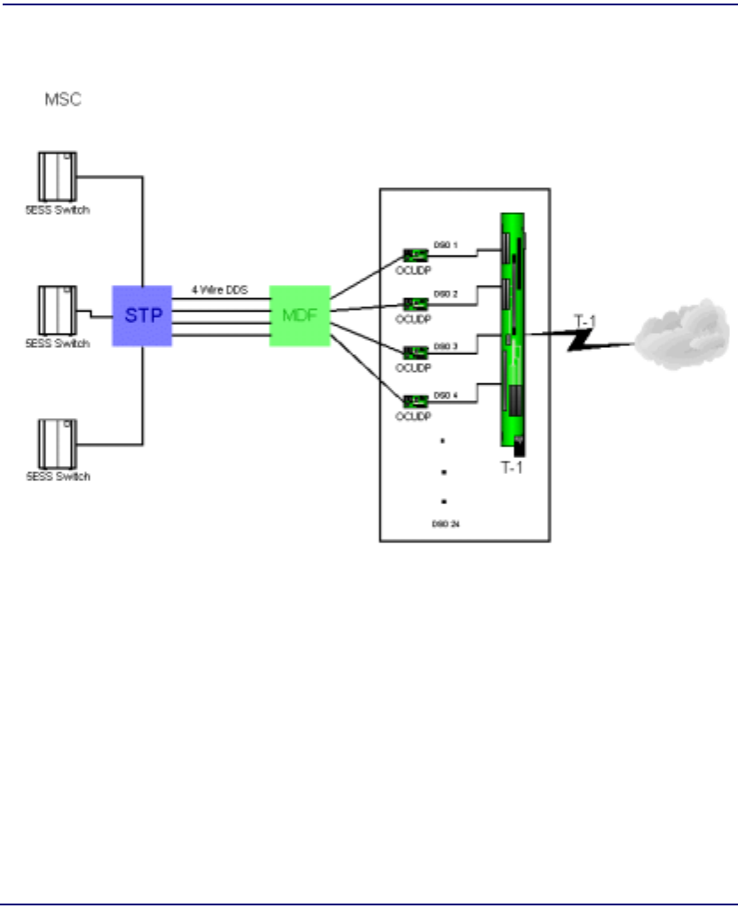
10-4 Compact T1 - Release 6.1
OCU-DP Card
Overview
SS7 Backhaul Application
In this application, the carrier uses the OCU to transfer signaling and call information
between MSCs.
Compact T1

Compact T1 - Release 6.1 10-5
OCU-DP Card
Features
Features
lProvides available baseband data rates from 2.4 to 72 Kbps
lSupports primary and secondary channel services, 64K clear channel service, and
4-wire Switched-56 service
lComplies with AT&T Pub. 62310
lOffers Bipolar Violation (BPV), Loss of Frame (LOF-DDSII), Loss of Signal
(LOS) and Out-of-Service (OOS) performance counters: 15 minute, 1 hour and
24 hour intervals available
lOffers BPV, OOS, LOF and LOS selectable alarm thresholds
lSupplies built-in self-tests including data path and RAM test status and TDM and
CSU failures
lSupports DDS network control codes for OCU, CSU and DSU latching and non-
latching service loopbacks
lSupports system timing from any T1 line and provides it to the connected DTE
lDeploys up to 24 OCU-DP service ports in a single chassis, or a total of 48
OCU-DP service ports in two side-by-side Compact T1s occupying just two rack
units of equipment space (19 inch rack)

10-6 Compact T1 - Release 6.1
OCU-DP Card
Technical Specifications
Technical Specifications
Controller Software Required
T1 Controller
lRelease 3.2 or higher is required
Service Interface
lSingle-port OCU-DP interface
-One RJ-48S front-panel jack
-Strap selections for rear-panel RJ-21X telco connector
lFour-port OCU-DP interface
-Four RJ-48S front-panel jack
-Strap selections for rear-panel RJ-21X telco connector
Network Interface
lEach OCU port DS0 cross-connected to T1 port
Loopbacks
OCU, CSU and DSU:
lManual loopbacks activate via CLI
lNon-latching loopbacks activate via network code
lLatching loopbacks activate via network code
Clocking
lLoop-timed from any T1 in the platform
lSources clock to the DTE device

Compact T1 - Release 6.1 10-7
OCU-DP Card
Technical Specifications
Power Consumption
l6 W maximum, Four Port OCU-DP card
l3 W maximum, Single Port OCU-DP card
Regulatory Approvals
USA
lUL60950
lFCC Part 15, Class A
lDesigned to meet NEBS Level 3 for type 2 and 4 equipment (not certified)
Canada
lCSA C22.2 No. 60950-00
lICES-003, Class A
Physical
lDimensions: 3.5 in. (H) x 0.75 in. (W) x 11.25 in. (D)
8.9 cm (H) x 1.9 cm (W) x 28.6 cm (D)
lWeight: 5.7 oz. (.16 kg)
For information on Compact T1 Environment required, see Installation Environment
on page 2-2.

10-8 Compact T1 - Release 6.1
OCU-DP Card
Card Configuration
Card Configuration
OCU-DP card options are set with the Command Line Interface (CLI). For additional
information on these commands, see Chapter 5, CLI Commands.
CLI Commands
Configuration Commands
l set (ocudp) baud
Set up OCU-DP port baud rate
l set (ocudp) loopdetect
Set OCU-DP non-latching/latching loopback code detection
l set (ocudp) mvec
Set Majority Vote Error Correction (MVEC)
l set (ocudp) secondary
Set up the secondary channel service
l set (ocudp) up/down
Set the OCU-DP line In or Out-of-Service.
Test Commands
l set (ocudp) loopback
Set the manual loopback tests
l set (ocudp) selftest
Start the OCU-DP self test
OCU-DP Status Commands
l show (ocudp)
Displays OCU-DP card configuration (baud, loopdetect, error correction,
switched and enhanced switched service and secondary channel
provisioning)
l status (ocudp)
Displays the status or performance statistics of the OCU-DP card (OOS,
LOF, LOS and BPV seconds)

Compact T1 - Release 6.1 10-9
OCU-DP Card
Card Configuration
Basic Setup
Command Description
set {ocudp-addr} baud
{2400|4800|9600|19200|38400|
56000*|64000}
Set the OCU-DP Baud rate.
Where ocudp-addr = {slot:port} of the
OCU-DP card to apply settings to.
set {ocudp-addr} up Set the OCU-DP port 1 up.
show {ocudp_card-addr} Show the OCU-DP card settings.
Where ocudp_card-addr = {slot} of the
OCU-DP card.
disconnect a Disconnects all connections to slot a
(controller)
set {ds0-addr} type data Sets a DS0 data signaling type
connect {ds0-addr}
{ocudp-addr}
Connects DS0 (in previous step) to OCU-DP
port (in previous step).
show connect
(ocudp_card-addr}
Displays connect information for OCU-DP
card.
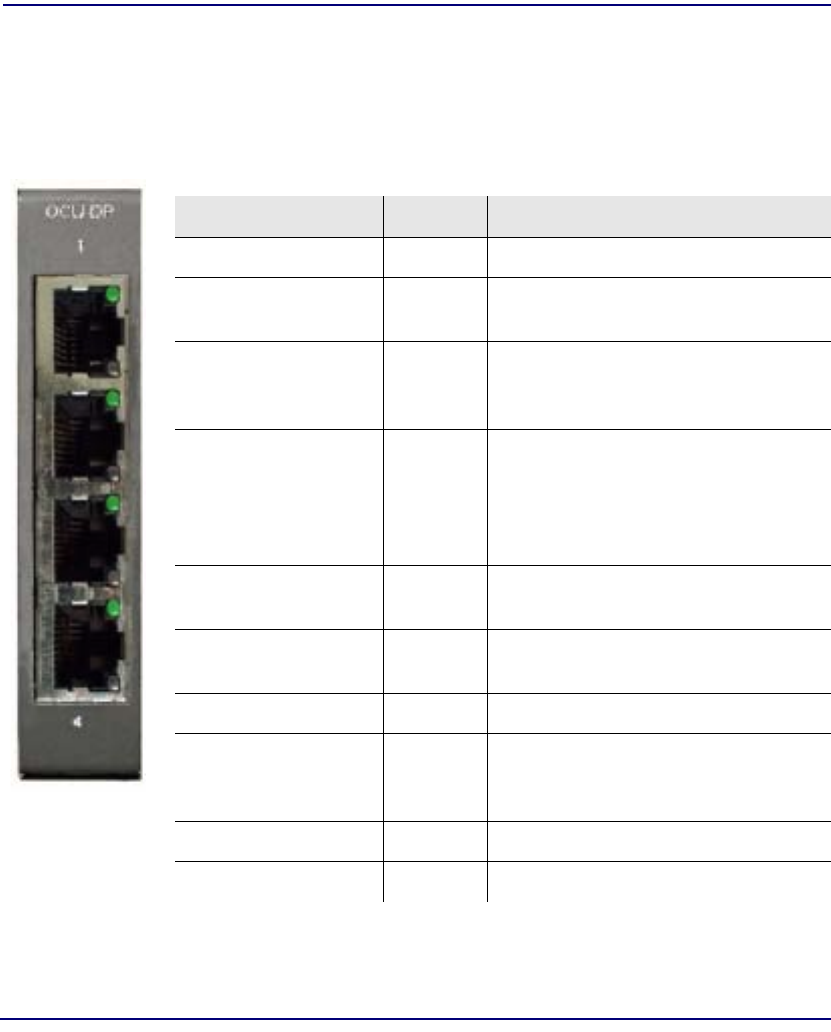
10-10 Compact T1 - Release 6.1
OCU-DP Card
LEDs
LEDs
There are two LEDs for each channel on the OCU-DP card. The function for each LED
is listed below:
State Description
Yellow Flickering ALL Boot Software in control.
Green (walking down)
Red (walking up) ALL Application Software in control
(repeated 3.5 times).
Red, slow flash ALL In Boot. Application flash code
checksums did not match and Boot is
waiting for application download.
Red ALL In Application code waiting for
Controller to issue SW/HW revision
request. This is the first request that
comes from the OCU-DP card manager
in the Controller.
Green
Yellow Top
Bottom Port in Self-test. Duration is 5-8
seconds.
Off Top
Bottom Port is set down (Out-Of-Service).
Green Top Port is receiving valid signals.
Red Top Port is receiving no signal (primary) or
no frame sync (secondary or clear
channel).
Red Flashing Bottom Port is receiving bipolar violations
Yellow Bottom Port is in loopback.
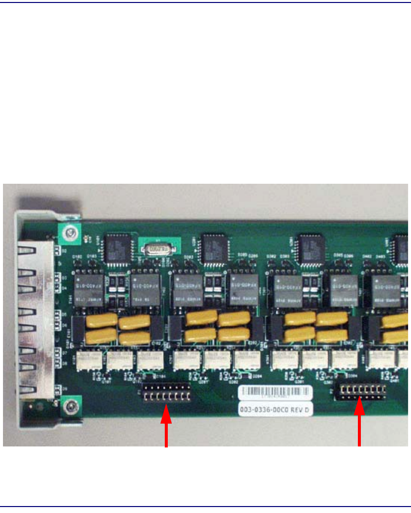
Compact T1 - Release 6.1 10-11
OCU-DP Card
Jumper Settings
Jumper Settings
The P1 and P2 Jumpers are defaulted to RJ-48S, which are the set of pins nearest the
bottom of the service card. With the jumper in this position the signals are routed to the
RJ-48S connector(s) on the face of the card. To route the signals to the 25-pin Telco
connector at the rear of the unit, move the jumpers to the backplane position, which is
the set of pins toward the top of the service card.
P1 applies to connectors 1 and 2 (connector 2 only with the 4 port card).
P2 applies to connectors 3 and 4 (for the four port card only).
P1 is set to P2 is set to
25-Pin TelcoRJ-48S Position Position
Top of Card
Front of
Card

10-12 Compact T1 - Release 6.1
OCU-DP Card
Alarms
Alarms
The OCU-DP cards and supporting Controller Software will support the following
alarms:
Alarm/
Event Severity Category Description Clear Mechanism
(alarms only)
Card
Detect Information Equipment OCU-DP card inserted
Card
Removed Information Equipment OCU-DP card removed
Out of
Service
(OOS)
Major Facility Network sending Out-of-
Service code (OOS) or
card has LOS.
Correct with Network or
replace or deprovision the
card.
Los of
Signal
(LOS)
Major Facility No signal at customer link. Correct with Customer
data path, replace the card,
or reconnect the drop.
Los of
Frame
(LOF)
Major Facility Framing patter not
detected at customer link. Correct with Customer
data path, replace the card,
or reconnect the drop.
Bipolar
Violation
(BPV)
Minor Facility Excessive violations on
customer interface. Correct with the incoming
signal, or deprovision card.

Compact T1 - Release 6.1 10-13
OCU-DP Card
Line Rates/Line Lengths
Line Rates/Line Lengths
All lengths were measured to meet a BER of 10-7 with up to 45 dB of cable attenuation
at the Nyquist frequency for 56, 64 and 72 Kbps, and 40 dB all other rates.
Service Data
Rate Primary Channel /
Secondary Channel Max. Loop Distance (24 AWG)
Primary Channel only/Primary &
Secondary Channel
2.4 Kbps 2.4 Kbps/3.2 Kbps 13.8 miles/12.7 miles (22.3 km/20.4 km)
4.8 Kbps 4.8 Kbps/6.4 Kbps 11.0 miles/10.0 miles (17.7 km/16.1 km)
9.6 Kbps 9.6 Kbps/12.8 Kbps 8.0 miles/13.3 miles (13.0 km/12.2 km)
19.2 Kbps 19.2 Kbps/25.6 Kbps 6.3 miles/5.9 miles (10.1 km/9.4 km)
38.4 Kbps 38.4 Kbps/51.2 Kbps 5.5 miles/5.3 miles (8.8 km/8.5 km)
56 Kbps 56 Kbps/72 Kbps 5.1 miles/4.7 miles (8.2 km/7.6 km)
64 Kbps 64 Kbps 4.7 miles (7.6 km)
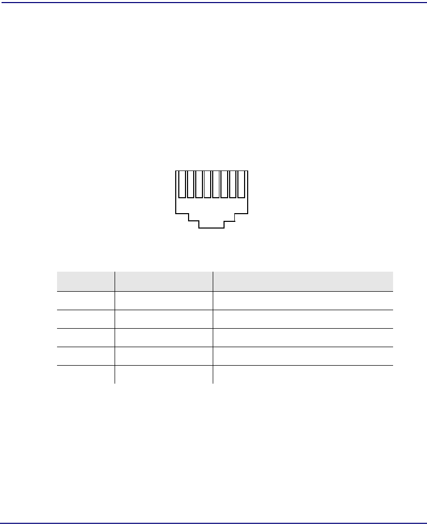
10-14 Compact T1 - Release 6.1
OCU-DP Card
Connector Pinouts
Connector Pinouts
The OCU-DP is part of the network, and connects to customer equipment.
DDS RJ-48S
The pinout for RJ-48S female is as follows:
Note: The above listed functions are relative to this port.
Pin Function Description
1 Receives Data (R-1) From Customer to Network Interface
2 Receives Data (T-1) From Customer to Network Interface
3-6 Not Used
7 Transmits Data (T) From Network Interface to Customer
8 Transmits Data (R) From Network Interface to Customer
18

Compact T1 - Release 6.1 10-15
OCU-DP Card
Connector Pinouts
25-Pair Telco Connector
Pinout for the Single (noted by an *) or Quad OCU-DP card. Must setup jumpers on
card to use this connector.
T1 and R1 = Receive. T and R = Transmit.
Note: The above information is relative to the connector.
J1 J2
Card Slot Line T1 R1 T R Card Slot Line T1 R1 T R
1 1*261272 4 1* 261272
2 283294 2 283294
3 305316 3 305316
4 327338 4 327338
2 1* 34 9 35 10 5 1* 34 9 35 10
2 36 11 37 12 2 36 11 37 12
3 38 13 39 14 3 38 13 39 14
4 40 15 41 16 4 40 15 41 16
3 1* 42 17 43 18 6 1* 42 17 43 18
2 44 19 45 20 2 44 19 45 20
3 46 21 47 22 3 46 21 47 22
4 48 23 49 24 4 48 23 49 24
50
25
26
1

10-16 Compact T1 - Release 6.1
OCU-DP Card
Connector Pinouts


11-2 Compact T1 - Release 6.1
Power Supply
115 VAC/-48 VDC Power Supply/Charger
115 VAC/-48 VDC Power Supply/Charger
The 115 VAC/-48 VDC Power Supply and Charger enables the Compact T1 to be
powered from either 115 VAC or -48 VDC sources, and includes an integral battery
charger and ringing generator. Integrating AC and DC power options, battery charger
and ringing generator functions in the Adit chassis dramatically reduces installation
time, space and cost requirements and inventory considerations in comparison to
separate power conversion or Uninterruptable Power Systems (UPS) equipment.
Front-panel LEDs provide easy-to-read indications of power input, battery status and
alarms. Remote notification to network operations and to monitoring centers of loss of
AC input or low DC input voltage is available via SNMP .
The ringing generator provides 25 Ringer Equivalence Number (REN) output,
supporting up to 48 FXS simultaneous ringing lines with normal cadence ringing.
Three ringer waveform shapes and three selectable ringer frequencies ensure
performance over a wide range of outside line or customer premises applications.
Features
lEnables Compact T1 to be powered from 115 VAC or -48 VDC source
lAutomatic switchover to Battery Backup Unit without power interruption
lSelectable ringer frequency settings of 20, 25 and 50 Hz
lIntegrated 25 REN ringing generator supports high capacity applications
lAutomatic switchover to Battery Backup Unit without power interruption
lInstalls quickly and easily with fully connectorized design
lSolid-state fuseless protection for Central Office NEBS and customer premises
FCC and UL safety requirements

Compact T1 - Release 6.1 11-3
Power Supply
Technical Specifications
Technical Specifications
AC Electrical Input
l115 VAC (95 to 132 VAC, 57 to 63 Hz), 2.5 A rms, 130 W maximum
lMaximum inrush current: 24 A peak at 132 VAC
lRear-panel mounted circuit breaker operates for overcurrent conditions greater
than 4 A
lFront-panel AC INPUT status LED
DC Electrical Input
l-48 DC (-40 to -60 V), 2.1 ADC, 90 W maximum
lMaximum cold start inrush current: 30 A peak at -60 VDC
lSolid-state input overcurrent protection trips at 2.5 A at 68º F (20º C)
lExtended mode: jumper option enables Compact T1 startup at low battery input
voltage
Electrical Output
l-37 VDC (short loop)/ -54 DC (long loop), talk battery, 1.45 A maximum
l-54 VDC battery charger output, 0.5 A maximum
l+5 VDC, 9 A maximum
lAutomatic switchover to battery backup without power interruption
Battery Charger
lFront-panel battery status LED
lBattery charging output limited to 0.5 A maximum
Alarms
Generates minor alarm contact closure on External Alarm Connector when
lAC input voltage is not present or circuit breaker is open
l -48 VDC battery input voltage magnitude is low or absent

11-4 Compact T1 - Release 6.1
Power Supply
Technical Specifications
Ringing Generators
lNominal 85 V rms (108 V rms max)
lReferenced to -54 VDC (-60 VDC max) output
lSupports three jumper-selectable ringer waveform shapes
lDrives 25 REN indefinitely with minimum output voltage of 65 V rms at normal
ringer cadence
lRinger frequency is selectable, 20 25 or 50 Hz ± 15%
lOverload protected
Regulatory Approvals
USA
lUL60950
lFCC Part 15, Class A
lNEBS Level 3 certified for type 2 and 4 equipment
GR-1089-CORE, GR-63-CORE
Canada
lCSA C22.2 No. 60950-00
lICES-003, Class A
Mexico
lNOM 19, Safety of Data Processing Equipment
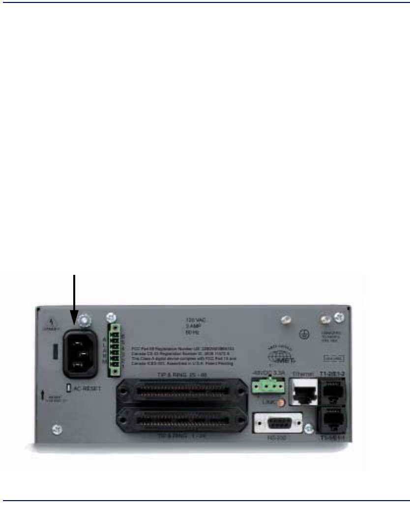
Compact T1 - Release 6.1 11-5
Power Supply
Input Power
Interface Connectors
lIEC-320, 15 A 3-prong AC power receptacle
lRear PCB connector: Compact T1 backplane
Physical
lDimensions: 3.5 in. (H) x 2 in. (W) x 12 in. (D)
8.9 cm (H) x 5.1 cm (W) x 30.5 cm (D)
lWeight: 115 VAC - 1 lb. 6 oz. (0.62 kg)
24 VDC - 1 lb. 9 oz. (0.71 kg)
For information on Compact T1 Environment required, see Installation Environment,
on page 2-2.
Input Power
The following graphic displays the back of the chassis with a 115 VAC/-48 VDC
Power Supply installed.
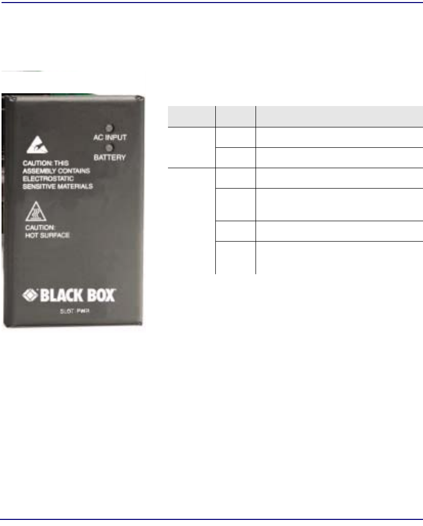
11-6 Compact T1 - Release 6.1
Power Supply
115 VAC LEDs
115 VAC LEDs
The power supply card has two LEDs, as described in the table below.
LED State Description
AC
Input Off AC input missing or failure
Green AC input present
Battery Off Battery input not used
Green Battery charging or operating from
DC source only.
Yellow Battery discharging
Red Battery low (less than 42V),
ringer disabled
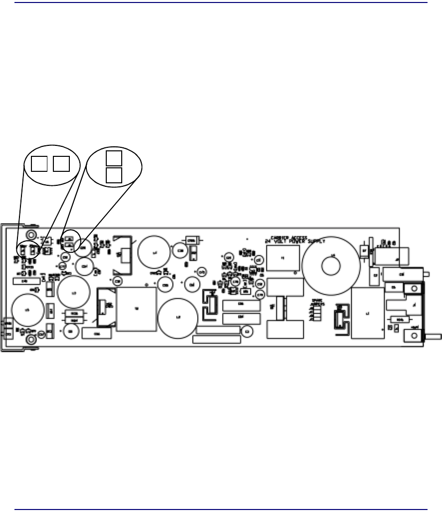
Compact T1 - Release 6.1 11-7
Power Supply
Ringer Waveform Options
Ringer Waveform Options
The default standard ringer waveform setting (for all three power supplies) will work
well in most applications. However, if there is a ringer detection problem with the
equipment, the user can alter the shape of the waveform by populating the jumpers on
the power supply as described below. The Ringer Frequency can be configured using
jumpers, as displayed below.
J7J8 J6
J5
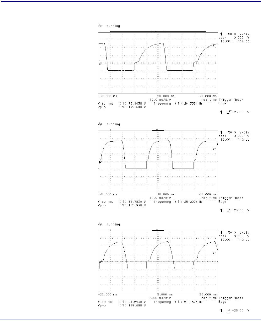
11-8 Compact T1 - Release 6.1
Power Supply
Ringer Waveform Options
Standard Waveform
The standard waveform
(default) should work
well for most applications.
Ringer Frequency: 20 Hz
Ringer Frequency: 25 Hz
Ringer Frequency: 50 Hz
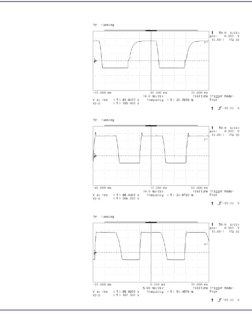
Compact T1 - Release 6.1 11-9
Power Supply
Ringer Waveform Options
Square Waveform
Ringer Frequency: 20 Hz
Ringer Frequency: 25 Hz
Ringer Frequency: 50 Hz
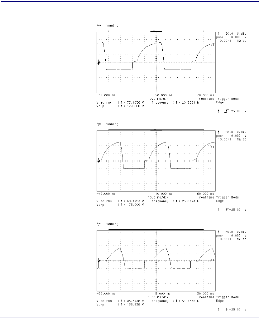
11-10 Compact T1 - Release 6.1
Power Supply
Ringer Waveform Options
Long Rise Time or Rounded Waveform
Ringer Frequency: 20 Hz
Ringer Frequency: 25 Hz
Ringer Frequency: 50 Hz
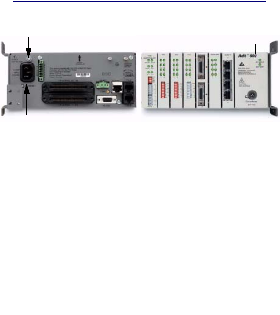
Compact T1 - Release 6.1 11-11
Power Supply
Replacing a Power Supply
Replacing a Power Supply
1. Disconnect power cord from the unit.
2. Remove nut and lock washer from power supply retention stud located directly
above power cord socket.
3. Remove power supply by grasping faceplate at top and bottom and pulling
power supply straight out of the case.
4. When installing the power supply, be certain to engage top and bottom edges
of power supply circuit board in the card guides located 1 1/4 inches inside the
front opening of the case.
5. Slowly slide the power supply into the case while making sure that the power
supply retention stud aligns with and passes through its attachment hole in the
rear of the case. Press gently on the faceplate of the power supply to ensure that
the connector on the power supply is fully mated to its mating connector on the
backplane.
6. Replace nut and lock washer on the power supply retention stud.
7. Reconnect the power cord to the unit.
Front
Back
Faceplate
Nut and lock washer
Power Cord
Connector

11-12 Compact T1 - Release 6.1
Power Supply
Replacing a Power Supply
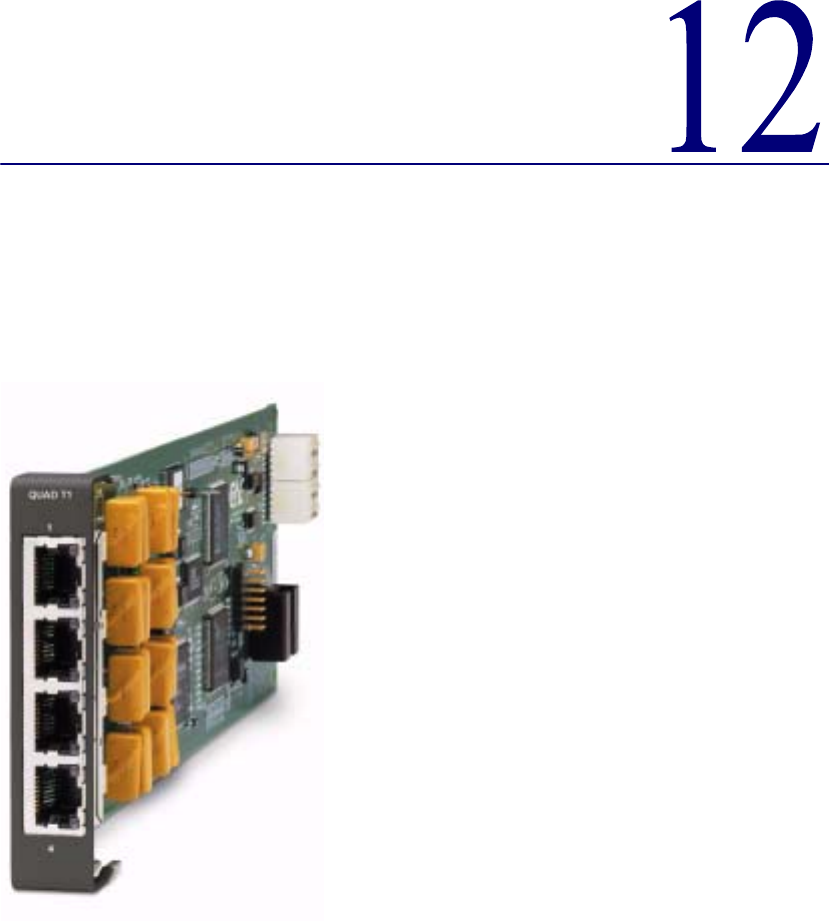

12-2 Compact T1 - Release 6.1
Quad T1 Card
Overview
Overview
The Quad T1 Service card enables service providers and enterprise network managers
to cost-effectively provision and expand network bandwidth or drop-side T1
bandwidth. The Quad T1 card can be inserted into any slot of the six-slot chassis and
supports an array of network access technologies, including full drop-and-insert
functionality, fractional and full T1 data and voice trunking.
When fully equipped with four Quad T1 Service cards plus the T1 Controller card an
Compact T1 can support can support up to 18 T1 access lines. This available bandwidth
enables the Adit to cost-effectively address small to medium sized business
requirements, multi-tenant units, fixed or mobile wireless backhaul, as well as end-
office applications. The flexible Quad T1 Service card allows physical connections to
either the front-panel 8-pin connector or the rear-panel 25-pair telco connectors.
As a component of the Compact T1 platform, the Quad T1 Service card provides
several local and remote management options through the Compact T1 Controller card.
The Quad T1 card can be locally configured and managed using the Command Line
Interface (CLI). Front-panel LEDs indicate each port’s activity and status.

Compact T1 - Release 6.1 12-3
Quad T1 Card
Features
Features
lIntegrates T1 CSU functionality with FCC registration for direct connection to
T1 lines
lSupports B8ZS or AMI encoding and SF (D4) or ESF framing
lFlexible system clock timing may be derived from any T1
lInsert up to four Quad T1 Service cards plus the Controller’s two T1s in a single
Compact T1 for a total of 18 T1s/CSUs per chassis
lSupplies up to 36 T1s in two Compact T1 occupying just two rack units of
equipment space (19-inch rack)
lAllows full non-blocking digital cross-connection (DCS) of all timeslots to any
Adit service card
lOffers solid-state fuseless protection for central office NEBS compliance and
customer premises FCC and UL safety requirements
Technical Specifications
Controller Software Required
T1 Controller
lRelease 1.3.1 or higher is required

12-4 Compact T1 - Release 6.1
Quad T1 Card
Technical Specifications
T1 Interface
lLine rate (transmitted): 1.544 Mbps ±50 bps
lSelectable B8ZS or AMI encoding
lSF (D4) or ESF framing
lIntegrated CSU
lLine Build Out (DSX-1): 655 feet
lReceive Sensitive (DS1): 0 to -22.5 dB
lJitter and wander ITU-T G.824 (3/93)
lSolid-state fuseless overvoltage and overcurrent T1 line protection
lChannel status LEDs
lFront or rear connections:
- Front: uses faceplate-mounted RJ-48C connectors
- Rear: uses rear-panel RJ-21X connectors
lLess than 3 ms signaling latency
lLess than 10 ms overall Adit system signaling latency
Network Interface
lThe Quad T1 Service card may be configured as either a network or drop-side
interface
Network Standards
lT1.107
lT1.102
lT1.203
lT1.231
lT1.403
Clocking
lAny one of the four T1 interfaces on a card may be selected by the controller as
the Adit platform timing source

Compact T1 - Release 6.1 12-5
Quad T1 Card
Technical Specifications
Alarms
lSupport standard T1.403 alarms
Testing and Diagnostics
lT1.403 payload loopbacks (ESF only)
lT1.403 remote and local line loopbacks (ESF and SF)
lDS0 loopbacks
lT1.231 Performance History (15 minute intervals, 24 hour totals)
lT1.203 Performance Report Messages (PRMs)
Power Consumption
lLess than 3 W per card
Regulatory Approvals
USA
lUL60950
lFCC Part 15, Class A
lFCC Part 68
lNEBS Level 3 certified for type 2 and 4 equipment
GR-63-CORE, GR-1089-CORE
Canada
lCSA C22.2 No. 60950-00
lICES-003, Class A
lCS-03
Physical
lDimensions: 3.5 in. (H) x 0.75 in. (W) x 11.25 in. (D)
8.9 cm (H) x 1.9 cm (W) x 28.6 cm (D)
lWeight: 5.1 oz. (0.14 kg)
For information on Compact T1 Environment required, see Installation Environment
on page 2-2.

12-6 Compact T1 - Release 6.1
Quad T1 Card
Card Configuration
Card Configuration
All options on the Quad T1 cards are set using the Command Line Interface (CLI). The
default for the connectors are the RJ-48s on the front of the T1card, however by moving
the jumpers to the backplane, the Telco connectors on the back of the unit are enabled.
See Jumper Settings on page 12-7 for more information.
CLI Commands
The following commands are used to configure the Quad T1 card. For detailed
information on these commands, see Chapter 5, CLI Commands.
l connect
Creates two-way connections between channels.
l disconnect
Removes a connection created by the connect command.
l set (ds1)
Sets up the DS1 interfaces (clock, up, down, equipment loopup, fdl, framing,
id string, lbo, line loopup, linecode, loopdetect, payload loopup, threshold).
l show (ds1)
Displays current settings for DS1 (circuit ID, up.down, framing, line coding,
clock source, line build out, loop code detection, loop back, fdl type).
l status (ds1)
Displays the status of the DS1 (receive, transmit, loopback).
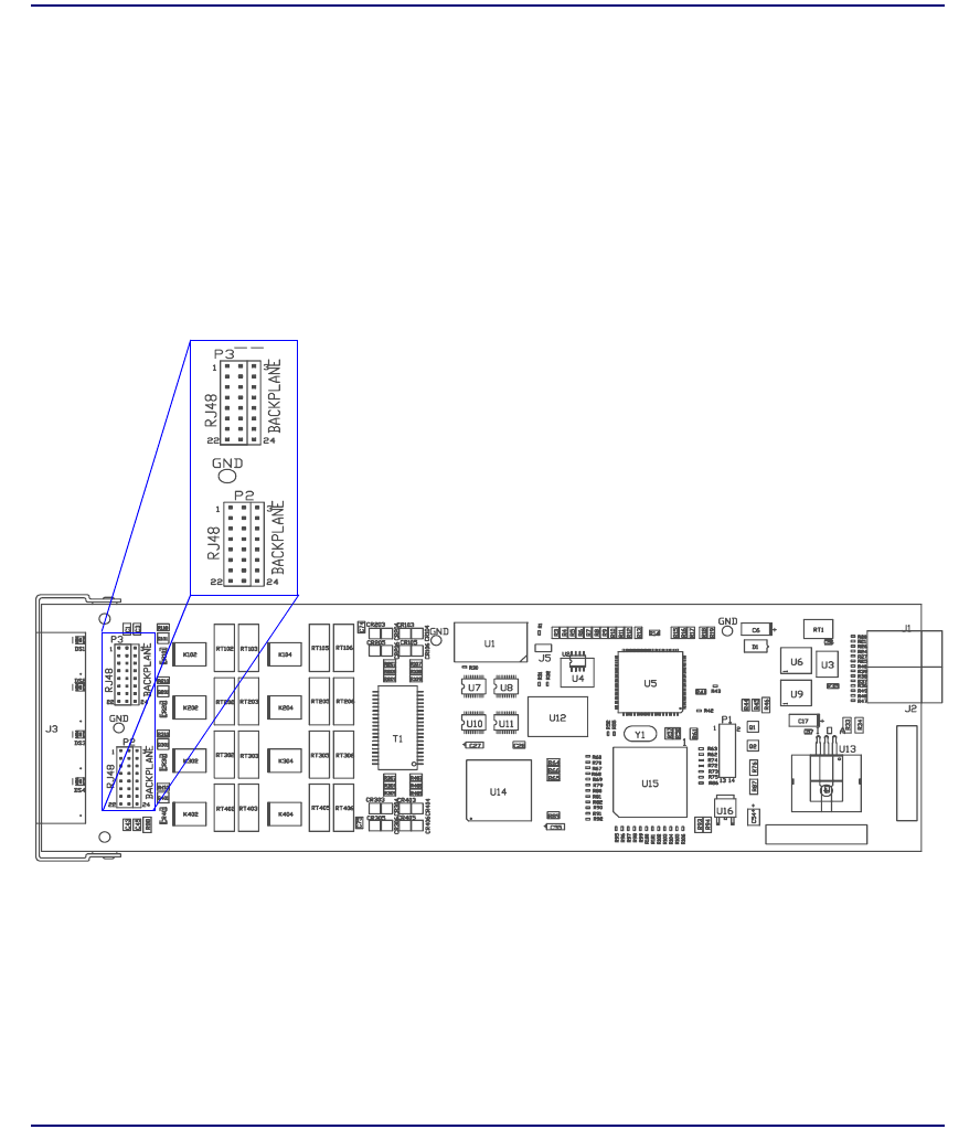
Compact T1 - Release 6.1 12-7
Quad T1 Card
Jumper Settings
Jumper Settings
The P2 and P3 Jumpers are defaulted to RJ-48, which are the set of pins nearest the
connectors. In this position the T1 signals (TX and RX) are routed to the RJ-48
connectors on the face of the card, see RJ-48 Connector on page 12-10 for pinout
information. To route the T1 signals to the 25-pin Telco connector at the rear of the
unit, move all the jumpers to the "backplane" position (the two rightmost pins for each
signal). See 25-pin Telco Connector on page 12-8 for pinout information.
P2 and P3 Jumpers
Front Back

12-8 Compact T1 - Release 6.1
Quad T1 Card
Connector Pinouts
Connector Pinouts
25-pin Telco Connector
The pinouts are as follows:
Slot Port Pair Pin
Location Function Color
Code
1 and 4 1 1 26
1
Tip Receive from DS1 network
Ring Receive from DS1 network
White
Blue
2 27
2
Tip Transmit to DS1 network
Ring Transmit to DS1 network
White
Orange
1 and 4 2 3 28
3
Tip Receive from DS1 network
Ring Receive from DS1 network
White
Green
429
4
Tip Transmit to DS1 network
Ring Transmit to DS1 network
White
Brown
1 and 4 3 5 30
5
Tip Receive from DS1 network
Ring Receive from DS1 network
White
Slate
631
6
Tip Transmit to DS1 network
Ring Transmit to DS1 network
Red
Blue
1 and 4 4 7 32
7
Tip Receive from DS1 network
Ring Receive from DS1 network
Red
Orange
833
8
Tip Transmit to DS1 network
Ring Transmit to DS1 network
Red
Green
2 and 5 1 9 34
9
Tip Receive from DS1 network
Ring Receive from DS1 network
Red
Brown
10 35
10
Tip Transmit to DS1 network
Ring Transmit to DS1 network
Red
Slate
50
25
26
1

Compact T1 - Release 6.1 12-9
Quad T1 Card
Connector Pinouts
2 and 5 2 11 36
11
Tip Receive from DS1 network
Ring Receive from DS1 network
Black
Blue
12 37
12
Tip Transmit to DS1 network
Ring Transmit to DS1 network
Black
Orange
2 and 5 3 13 38
13
Tip Receive from DS1 network
Ring Receive from DS1 network
Black
Green
14 39
14
Tip Transmit to DS1 network
Ring Transmit to DS1 network
Black
Brown
2 and 5 4 15 40
15
Tip Receive from DS1 network
Ring Receive from DS1 network
Black
Slate
16 41
16
Tip Transmit to DS1 network
Ring Transmit to DS1 network
Yellow
Blue
3 and 6 1 17 42
17
Tip Receive from DS1 network
Ring Receive from DS1 network
Yellow
Orange
18 43
18
Tip Transmit to DS1 network
Ring Transmit to DS1 network
Yellow
Green
3 and 6 2 19 44
19
Tip Receive from DS1 network
Ring Receive from DS1 network
Yellow
Brown
20 45
20
Tip Transmit to DS1 network
Ring Transmit to DS1 network
Yellow
Slate
3 and 6 3 21 46
21
Tip Receive from DS1 network
Ring Receive from DS1 network
Violet
Blue
22 47
22
Tip Transmit to DS1 network
Ring Transmit to DS1 network
Violet
Orange
3 and 6 4 23 48
23
Tip Receive from DS1 network
Ring Receive from DS1 network
Violet
Green
24 49
24
Tip Transmit to DS1 network
Ring Transmit to DS1 network
Violet
Brown
NA NA 25 50
25
Reserved Violet
Slate
Slot Port Pair Pin
Location Function Color
Code
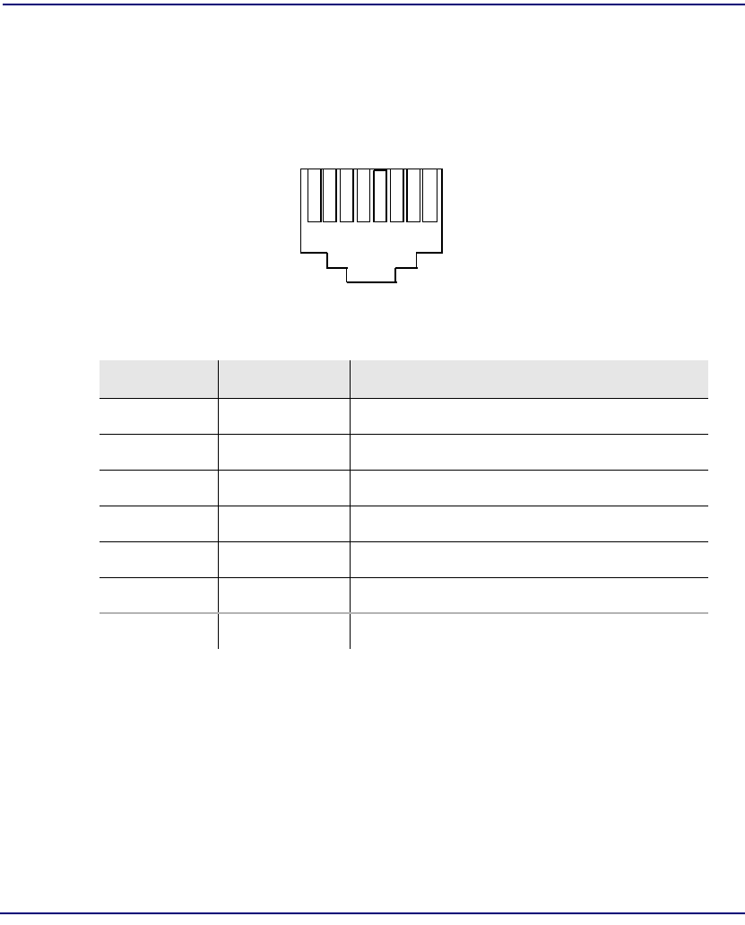
12-10 Compact T1 - Release 6.1
Quad T1 Card
Connector Pinouts
RJ-48 Connector
There are four RJ-48C (female) connectors on the front of the Quad T1 Card.
The pinouts are as follows:
Pin Name Description
1 Receive Ring Receive from DS1 network
2 Receive Tip Receive from DS1 network
3 n/c Not connected
4 Transmit Ring To DS1 network
5 Transmit Tip To DS1 network
6 - 7 n/c Not connected
8 Chassis Ground
18
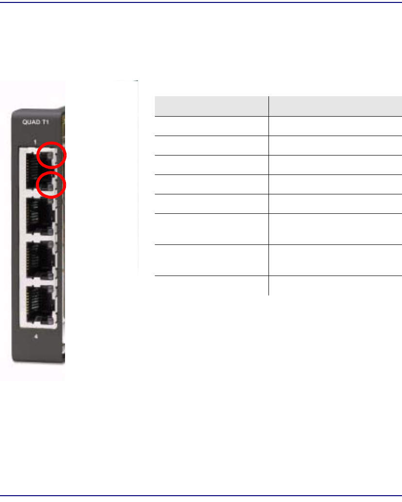
Compact T1 - Release 6.1 12-11
Quad T1 Card
LEDs
LEDs
Each channel on the Quad T1 card has two LEDs. The description of the top LED is
shown below, the bottom LED is not used with this application.
State Description
Off Off line
Green Normal
Red Loss of Signal (LOS)
Yellow Bipolar Violation (BPV)
Flashing Green Loopback active
Flashing Yellow Yellow Alarm
(Remote Alarm Indication)
Flashing Red (Slow) Loss of Frame (LOF) or Alarm
Indication Signal (AIS)
Flashing Red (Fast) Self-test Failure
Top LED
(active)
Bottom LED
(not used)
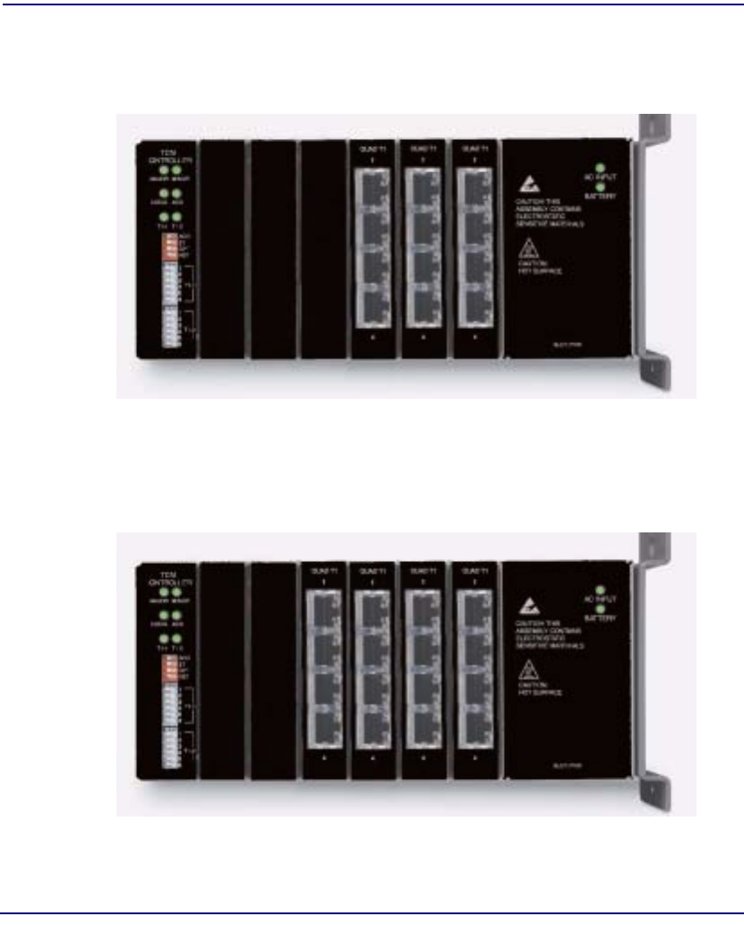
12-12 Compact T1 - Release 6.1
Quad T1 Card
Configuration Restrictions
Configuration Restrictions
There are some configuration restrictions with the Quad T1 Service Card.
If an Compact T1 contains three (3) Quad T1 cards:
lremaining three (3) slots can be any combination of BRI, FXS, FXO or Router
cards.
lremaining three (3) slots can contain two (2) V.35 cards, with the remaining slot
empty.
If an Compact T1 contains four (4) Quad T1 cards:
lremaining two (2) slots must be empty.


13-2 Compact T1 - Release 6.1
Router (IP) Card
Overview
Overview
The fast-changing world of IP services requires products with the capability to generate
new value-added revenues. The IP Router Service card offers the performance and
expandability of a dedicated router in a low-cost solution with simple integrated
management through the Adit platform.
Unlike other internal routing solutions that support software-based routing by adding
bundles to the system software, the IP Router card employs a dedicated processor to
ensure high performance and product feature expansion. It delivers high-speed Internet
and Intranet connectivity to small and medium-sized businesses, as well as remote and
branch office users. A powerful set of standard features includes IP and IPX routing,
Layer 2 bridging, ML-PPP, networking security, and management capabilities to
integrate services in the digital last mile.
The Compact T1 supports up to six IP Router cards, in any slot, or other combinations
of services. This flexibility enables service providers to target multi-tenant units with a
single device that supports business-class voice, Internet access and data services. The
addition Multi-Link Point-to-Point Protocol (ML-PPP) to the IP Router card ensures
that service providers can continue to support the growing needs of customers, beyond
one or two T1s.
The IP Router card simplifies delivery of data networking solutions by leveraging the
advantages of the single IP management, while reducing costly cabling expense
through a direct 10/100Base-TX Ethernet interface connection.
IP Router cards are easily managed through the Compact T1 user interface, identified
by a single IP address. With this capability, multiple cards within a single Compact T1
can be configured, monitored and maintained through one unique IP address, speeding
installation and simplifying management tasks.
The IP Router card is SNMP, CLI or menu-driven manageable. Management
connectivity is provided either through the user data port connection on the IP Router
card, the local RS-232 craft port, the Ethernet management port, or the dedicated
management channel on the T1 Controller.
The Router Service card configuration information can be uploaded to the NOC while
router code upgrades are loaded to the Router card. The uploading and downloading is
accomplished through the Ethernet management port and/or the user data connection.
In addition, the CLI management option enables management configuration
information to be created offline and loaded into the system either via a script or TFTP.

Compact T1 - Release 6.1 13-3
Router (IP) Card
Features
Features
lSupplies auto-sensing 10/100Base-TX Ethernet
lSupports up to 6 router cards per Compact T1
-Multi-point networking with up to 24 WAN connections per router
-Each WAN connection can be provisioned with multiple DS0s
-Deliver more than two T1s bandwidth per Router card; up to 60 DS0s per
Router card
-Enables multiple T1 facilities to function as a single IP WAN interface using
ML-PPP for bandwidth scalability beyond a single T1
lEnsures high performance and feature expansion through dedicated IP Router
card processor
lEnables management via menu-driven user interface or CLI Router interface
lSupports packet filtering and Spanning Tree Protocol
lAllows Network Address Translation (NAT) and Port Address Translation
(PAT)
lSupports Dynamic Host Configuration Protocol (DHCP)
lDelivers a minimum of 3,000 packets per second
lRADIUS Login Authentication
Technical Specifications
Controller Software Required
T1 Controller
lRelease 3.0 or higher is required

13-4 Compact T1 - Release 6.1
Router (IP) Card
Technical Specifications
Management
lMenu-driven over RS-232 and CLI
lPing, SNMP, Telnet over IP
lEthernet management port
lIP management connection via T1 FDL, Ethernet and DS0 bearer channel
lCode download via TFTP
lConfiguration upload and download via TFTP
WAN Interface
lAny T1 interface on the Compact T1 platform
lUp to 24 WAN interfaces per router
lUp to 60 DS0s bandwidth per router
lPPP, Frame Relay, PPP in Frame Relay, MLPPP and GRE tunneling
LAN Interface
lA single 10/100Base-TX auto-sensing port
Routing
lIPX RIP/SAP
lIP RIPv1, RIPv2, RIPv/RIPv2 compatibility mode
lStatic routing
lClassless routing (CIDR)
Bridging
lIEEE 802.1D MAC bridging
Router Performance
lMinimum of 3,000 64-byte packets per second throughput

Compact T1 - Release 6.1 13-5
Router (IP) Card
Technical Specifications
Advanced Capabilities
lDHCP server
lSyslog
lSNTP
lSpanning Tree Protocol
lVan Jacobson message header compression
lDomain Name Server (DNS) proxy
lIP fragmentation and reassembly support
lSecondary IP Address
Frame Relay
lRFC 1490 encapsulation
lANSI T1.617 Annex D LMI
lITU Q.933 Annex A LMI
Filtering
lLAN/WAN Filters up to Layer 4, stateful
Security
lThree user accounts
lThree levels of security
lPAP and CHAP
lNetwork Address Translation (NAT)
lNAT Bypass
lPort Address Translation (PAT)
lRADIUS Login Authentication

13-6 Compact T1 - Release 6.1
Router (IP) Card
Technical Specifications
MIBs
lRFC 1212 (Concise MIB)
lRFC 1213 (MIB II)
lRFC 1643 (Ethernet)
lRFC 2233 (Interface)
lRFC 2011 (IP)
lRFC 1471 (LCP/PPP)
lRFC 1473 (IP/PPP)
lRFC 2115 (Frame Relay)
lRFC 1406 (DS1/E1)
lRFC 1659 (RS-232)
lEnterprise MIB
Clocking
lLoop-timed from any T1 or the internal system clock
lSimple Network Time Protocol (SNTP) support for timing from a separate
network
Testing and Diagnostics
lPing
lWAN Monitor
Power
lLess than 2 W

Compact T1 - Release 6.1 13-7
Router (IP) Card
Technical Specifications
Regulatory Approvals
USA
lUL60950
lFCC Part 15, Class A
lNEBS Level 3 certified for type 2 and 4 equipment
GR-63-CORE, GR-1089-CORE
Canada
lCSA C22.2 No. 60950-00
lICES-003, Class A
Mexico
lNOM 19, Safety of Data Processing Equipment
Physical
lDimensions: 3.5 in. (H) x 0.75 in. (W) x 11.25 in. (D)
8.9 cm (H) x 1.9 cm (W) x 28.6 cm (D)
lWeight: 5.2 oz. (0.15 kg)
For information on Compact T1 Environment required, see Installation Environment
on page 2-2.

13-8 Compact T1 - Release 6.1
Router (IP) Card
Card Configuration
Card Configuration
The IP Router has the option of configuration through CLI or the Router menu-driven
user interface, which is accessed through Telnet. The following CLI commands are all
Router related. For information on the IP Router menu-driven user interface, see the IP
Router User Manual.
NOTE: The default IP address for the IP Router is 10.0.0.1.
CLI Commands
For detailed information on the following Router commands, see Chapter 5, CLI
Commands.
l add (router) dns proxy
Enable DNS proxy and add a remote DNS server address to the router card
l add (router) remote
Add a remote WAN profile to the WAN profile table
l add (router) snmp community
Add a SNMP community to an interface on the router card
l add (router) snmp trap
To specify a destination to send SNMP trap messages
l add (router) uploaduser
To specify a host that is allowed to upload configuration/software files
l add (router-lan) filter
Add address filters (address, custom, protocol) to the table of Layer 2 filters
applied to the specified LAN interface
l add (router-lan) static
Add static elements on the specific LAN interface (IP address, IP network,
IPX network, MAC address).
l add (router-wan) firewall
Add a firewall rule to a WAN.
l add (router-wan) gre network
Add a "by network" GRE tunnel to a WAN.

Compact T1 - Release 6.1 13-9
Router (IP) Card
Card Configuration
l add (router-wan) nat bypass
Add subnets to the list of source addresses that will not be subject to NAT
translation when passing through a NAT enabled WAN interface.
l add (router-wan) static
Add static elements to the specified WAN interface (IP address, IP network,
IPX network, MAC address and NAT address).
l clear (router) ip address table
Flush the learned entries from the IP address table for the specific interface
from the specified Router card.
l clear (router) mac address table
Flush the learned entries from the MAC address table for the specific
interface from the specified router card.
l connect (router-trunk) (t1)
Creates two-way connections between the router port trunk connections and
any DS0 channels of the service card or Controller.
l delete (router) dns proxy
Remove a remote DNS server address from the specified Router card.
l delete (router) remote
Delete a remote WAN profile from the WAN profile table.
l delete (router) snmp community
Delete an SNMP community entry.
l delete (router) snmp trap
Delete a trap destination from the router card.
l delete (router) uploaduser
Remove an existing authorized uploaduser.
l delete (router-lan) filter
Remove a a single filter rule from the table of Layer 2 filters applied to the
specified LAN interface.
l delete (router-lan) static
Remove a static element from the LAN interface (IP address, IP network,
IPS network and MAC address).
l delete (router-wan) firewall
Remove a firewall rule from a WAN.

13-10 Compact T1 - Release 6.1
Router (IP) Card
Card Configuration
l delete (router-wan) gre network
Remove a "by network" GRE tunnel to a WAN.
l delete (router-wan) nat bypass
Delete an IP subnet or host from the list of source addresses that will not be
subject to NAT translation when passing through a NAT enabled WAN
interface.
l delete (router-wan) static
Remove a static element from the WAN interface (IP address, IP network,
IP network, MAC address).
l disconnect {slot:port:trunk}
Removes a connection created by the connect {trunk-addr}{t1-addr}
l install (slot) router
Will prepare the controller for the insertion of a new router card that will
keep its currently loaded configuration.
l load tftp
Will download software via TFTP to the Controller or the Router card.
l rename (router) (router-wan/lan)
Change the name of a remote WAN or local LAN profile on the Router card.
l reset (router)
Reboot the Router. All new configuration will be in-use.
l rtrping
Router will perform a ping test and report the result.
l set (router) autologout
Set the period of time on inactivity after which the user will be automatically
logged-out of a Telnet session
l set (router) default
Reset the Router card to its default configuration settings.
l set (router) dhcp
Disable both DHCP server and DHCP relay functionality for the Router.
l set (router) dns
Configure the Domain Name Server (DNS) options.
l set (router) enhanced security
Enable/disable enhanced login security on the Router

Compact T1 - Release 6.1 13-11
Router (IP) Card
Card Configuration
l set (router) lmi
Specify the Local Management Interface (LMI) protocol to use for the
Router.
l set (router) log
Set password access on the Router card (access level, password)
l set (router) login auth
Sets how login authentication for this router should be performed
l set (router) login prompt
Enable/disable the suppression of the Router login prompt for a user that
telnets in from the Controller CLI
l set (router) ntp
Set Network Time Protocol (NTP) parameters
l set (router) password
Manage password access on the specified Router card
l set (router) ppp auth
Set the PPP authentication on the specified Router card
l set (router) ppp security
Set up the local external security server which the Router card will use to
authenticate remote PPP devices
l set (router) proxy
Configures Router in-use basics (up, down and proxy).
l set (router) reboot
Set automatic reboot after an upload of code or configuration file.
l set (router) rip
Specify version of RIP packets to transmit and receive.
l set (router) snmp
Set the value of sysContact, sysLocation and sysName on the Router.
l set (router) stp
Setup the Spanning Tree Protocol on the Router.
l set (router) syslog
Configure the Router to send alarm and event messages to a Syslog server
l set (router-lan) collision
Set the collision alarms (interval and threshold).

13-12 Compact T1 - Release 6.1
Router (IP) Card
Card Configuration
l set (router-lan) filter forward
Set the forwarding mode for Layer 2 filters added to the specified LAN
interface.
l set (router-lan) framing
Set which ethernet frame types are supported on the Router LAN interface.
l set (router-lan) gateway
Specify a default IP gateway for the specified LAN interface.
l set (router-lan) ip address
Specify an IP address for the specified LAN interface.
l set (router-lan) ipx network
Specify an IPX network numbers for the four IPX LAN frame types.
l set (router-lan) phy
Specify the ethernet PHY (physical specifications) speed and mode.
l set (router-lan) rip
Set the IP RIP for the LAN interface.
l set (router-lan) stp
Setup the Spanning Tree Protocol on this interface.
l set (router-lan) up/down
Set the LAN interface up or down.
l set (router-trunk) encapsulation
Specify the encapsulation to use on the Router interface.
l set (router-trunk) multilink group
Specify that a trunk is part of a multilink PPP group
l set (router-trunk) up/down
Set the Router trunk up or down.
l set (router-wan) dlci
Configure the DLCI for a specified WAN interface that will be using a frame
relay encapsulated trunk.
l set (router-wan) gre
Configure the GRE tunneling for a specified WAN interface.
l set (router-wan) ip
Set the IP traffic handling on the WAN interface.

Compact T1 - Release 6.1 13-13
Router (IP) Card
Card Configuration
l set (router-wan) ip address
Set the IP address for a WAN interface.
l set (router-wan) ipx
Set the IPX traffic handling on the specified WAN interface.
l set (router-wan) nat
Configure Network Address Translation (NAT) on a specified WAN
interface.
l set (router-wan) other
Set traffic handling of protocols other than IP or IPX on the specified WAN
interface.
l set (router-wan) ppp
Configure PPP on the specified Router card.
l set (router-wan) rip
Set the type or RIP updates on the WAN interface.
l set (router-wan) stp
Configure the Spanning Tree Protocol on the WAN interface.
l set (router-wan) trunk
Configure the trunk port for a specified WAN interface.
l set (router-wan) up/down
Set the specified WAN interface up or down.
l show (router)
Displays the current Router settings (DHCP, DNS proxy, LMI, PPP, RIP,
SNMP, STP, syslog and uploaduser).
l show (router) dhcp
Displays the current DHCP settings for the Router
l show (router) dns
Displays the current DNS setup for the router card
l show (router) dns proxy
Displays the current DNS Proxy setup for the router card
l show (router) lmi
Displays the current Local Management Interface (LMI) settings
l show (router) ntp
Displays the settings for NTP options

13-14 Compact T1 - Release 6.1
Router (IP) Card
Card Configuration
l show (router) ppp
Displays the current Local PPP (Point-to-Point Protocol) authentication and
security settings for the router
l show (router) rip
Displays the current RIP settings for the Router
l show (router) snmp
Displays the current SNMP settings for the Router
l show (router) stp
Displays the current Spanning Tree Protocol settings for the router
l show (router) syslog
Displays the current Syslog setup for the router
l show (router) uploaduser
Displays the current list of users allowed to upload and download
configuration and code files
l show (router-lan)
Displays the settings for the router card
l show (router-lan) collision
Displays the current LAN collision alarm settings for the router
l show (router-lan) filter
Displays the current LAN Layer 2 data filters applied to the LAN on the
router
l show (router-lan) static
Displays the current list of static entries for the LAN on the router
l show (router-lan) stp
Displays the current Spanning Tree Protocol settings for the LAN interface
l show (router-wan)
Displays the current Router WAN settings (firewall, PPP, static entries, STP
and trunk).
l show (router-wan) nat bypass
Displays the current list of NAT bypass entries for the WAN interface on the
specified Router card.
l status (router)
Displays the current Router status information

Compact T1 - Release 6.1 13-15
Router (IP) Card
Card Configuration
l status (router) channels
Displays a condensed status report of all voice channel endpoints
l status (router) dns
Displays the current state of the DNS resolver and entries in the DNS cache
l status (router) events
Displays the current event log from the router
l status (router) ip address table
Displays the current IP address table for the specified Router
l status (router) ip network table
Displays the current table of learned IP Networks for the specified interface
on the router card
l status (router) ipx network table
Displays the current table of learned IPX Networks for the specified
interface on the router card
l status (router) ipx server table
Displays the current table of learned IPX Servers for the specified interface
l status (router) mac address table
Displays the current table of learned MAC Addresses for the specified
interface on the router card
l status (router) performance
Displays the current runtime statistics from the specified router
l status (router) stp
Displays the current Spanning Tree state from the specified router
l status (router-lan)
Displays the current Router status information
l status (router-trunk)
Displays the current status for the specified trunk on the Router card.
l store
Save a software file from a defined slot to a defined location on a PC, via
TFTP.
l telnet (router)
Establish a Telnet session from the Compact T1 CLI to the Router port user
interface.

13-16 Compact T1 - Release 6.1
Router (IP) Card
Connector Pinouts
Connector Pinouts
Ethernet
The pinout for the RJ-48C (female) connector on the front of the card is as follows:
Pin Name Description
1 Receive + Receive from network
2 Receive - Receive from network
3 Transmit + Transmit to network
4 N/C Not connected
5 N/C Not connected
6 Transmit - Transmit to network
7 N/C Not connected
8 N/C Not connected
18
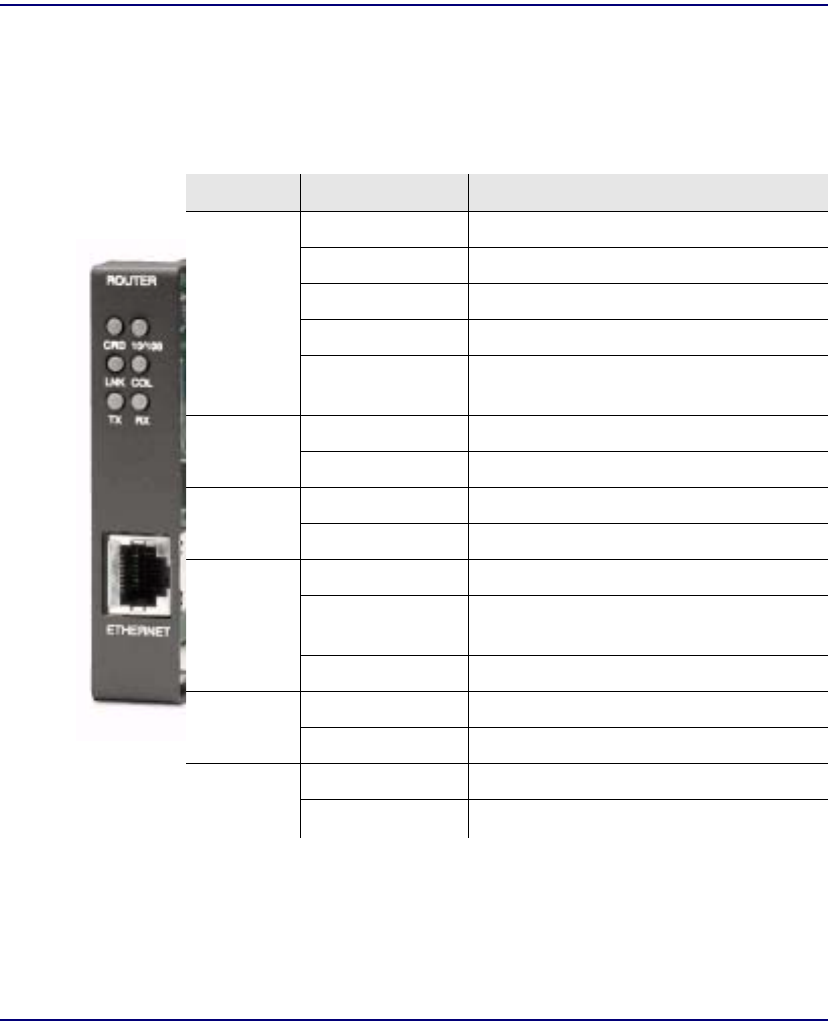
Compact T1 - Release 6.1 13-17
Router (IP) Card
LEDs
LEDs
The following chart describes each LED, and it’s state, of the Router card.
LED State Description
CRD Off Loss of power
Green No current alarms
Red Alarm state active. See alarm log for cause
Red Flashing Self-test or Boot in-process
Yellow Flashing Card is saving data to flash RAM, do not
power down
10/100 Off 10 Mb ethernet
Green 100 Mb ethernet
LNK Off No ethernet link
Green Good ethernet link
COL
Off No current ethernet transmit collisions
Yellow Ethernet collisions have occurred and
have not dropped to minimum level
Yellow Flashing Ethernet collision occurring
TX Off No ethernet transmit activity
Green Ethernet transmit activity
RX Off No current ethernet receive activity
Green Current ethernet receive activity

13-18 Compact T1 - Release 6.1
Router (IP) Card
LEDs


14-2 Compact T1 - Release 6.1
Router (CMG) Card
Overview
Overview
The Customer Media Gateway (CMG) Service card for the Compact T1 platform
combines IP Router functionality with the ability to translate circuit-based voice
services into packet-based voice services, or Voice over IP (VoIP). The CMG Service
card provides a cost-effective migration path for both existing Compact T1 TDM-based
deployments and greenfield VoIP applications.
When installed in an Compact T1, the CMG Service Card enables the packetization of
voice services using the Media Gateway Control Protocol (MGCP). This allows
standards-based voice processing, call control and signaling communications with the
service provider’s call agent or softswitch. The card also provides IP routing and
bridging between LAN and WAN connections for VoIP and data traffic, plus IP QoS/
policy management features – facilitating a truly integrated, packet-based voice and
data delivery solution.
Under control of the call agent, the CMG Service Card equips the service provider to
offer revenue generating CLASS and IP Centrex calling features, enabling service
migration from traditional Class 5 architectures to softswitch solutions. Distinctive
ringing, call waiting, DTMF tone detection, call progress tone generation, and caller ID
are just some of the many signaling and service solutions that are offered through the
CMG Service card.
With the availability of the CMG Service Card, the Compact T1 becomes the first
broadband service distribution gateway that supports modular voice services over IP,
providing voice/data policy management as an integrated, coordinated, platform-wide
capability. The integrated routing protocols ease network deployments, while the IP
class-of-service traffic management features simplify the aggregation of sensitive
voice packet streams into a multi-service converged data network.
As a component of the Compact T1 platform, the CMG Service card provides several
local and remote management options. The card can be locally configured and
managed using the menu-based interface, a Command Line Interface (CLI) via the on-
card user dataport or through the Compact T1 Controller. Remote management is
accomplished directly from the Compact T1 Controller over an in-band DS0
management channel, a separate SNMP network management facility, or in-band via
any configured IP WAN interface.

Compact T1 - Release 6.1 14-3
Router (CMG) Card
Features
Features
lProvides up to 48 channels of uncompressed voice mediation (VoIP) or T1/DS0
channels
lUp to eight T1s of VoIP conversion per Compact T1
lSupports voice/fax/modem calls, voice compression, silence suppression,
comfort noise generation, and echo cancellation
lUtilizes standards-based softswitch call control: MGCP (IETF version 0.1, 1.0,
1.0 bis, and, NCS)
lSupplies 10/100Base-TX Ethernet LAN Interface for mediated voice or local
LAN traffic
lEnables WAN routing with IP packet switching, filtering and policy enforcement
lSupports routing protocols: RIP V1 & V2
lIncludes WAN data protocols (T1 WAN): PPP, PPP over Frame Relay, Frame
Relay (RFC1490) and ML-PPP
lSupports multiple softswitch types
lEnables a variety of Centrex and CLASS services
lConfigurable tone databases allows tone files support world-wide tailoring of
call-progress tones and cadences to meet in-country specifications
lSelectable FXS impedances provide world-wide coverage of line impedance
variations and companding types
lSupport for cross-connects between data cards (CMG, IP Router, and V.35)
across the backplane enhances flexibility of data network configurations and
connections to existing data infrastructure

14-4 Compact T1 - Release 6.1
Router (CMG) Card
Technical Specifications
Technical Specifications
Controller Software Required
T1 Controller
lCompact T1 release 4.0 or higher to support a CMG Service card
lCompact T1 release 5.0 or higher and CMG release 1.1 or higher to support all
features listed in this chapter
Management
lMenu-driven over RS-232 connection or Telnet
lPing, SNMP, Telnet support
lEthernet management port
lIP management connection via T1 FDL, Ethernet, IP/DS0 bearer channel and
in-band WAN
lSoftware upgradeable via TFTP
lConfiguration upload and download via TFTP
Voice and Packet Interfaces
lVoice/Fax/Modem - up to 48 designated FXS or DS0 channels
lLAN - 10/100Base-TX port on card
lWAN - designated Adit T1 lines and channel groups (IP over PPP, Frame Relay,
PPP over Frame Relay, MLPPP)
lInternal - backplane cross-connect interfaces to other data cards (CMG, IP Router
or V.35)

Compact T1 - Release 6.1 14-5
Router (CMG) Card
Technical Specifications
Voice Processing and Mediation
lVoice coding using G.711, G.726-16, G.726-24, G.726-24, G.726-32, G.726-40
lCapacity of 48 channels of PCM, 24 channels of compressed codecs
lConcentration (over-subscription) of voice channels supported for compressed
codecs
lG.168 echo cancellation (up to 64 ms)
lRTP packetization (over UDP/IP)
l10-30 ms packetization time
lTOS prioritization
l160 ms jitter buffer, dynamic delay adjustment
lRTCP performance reporting
lCall progress tone and cadence generation via provisionable tone files
Connection Types (Media Flows)
lTDM-to-Packet or Hairpin (TDM-TDM)
l2-way, 1-way, Inactive (for call hold)
l2 connections per endpoint (for call waiting, transfer)
l3-way conferencing
Routing and Policy Management
lIPX RIP/SAP, RIP V1/2 static routing and Classless Inter-Domain Routing
(CIDR)
lPAP and CHAP
lNAT, NAT bypass and PAT
lDHCP
lDNS Proxy
lSpanning Tree Protocol
lFirewall filtering
lVoice prioritization

14-6 Compact T1 - Release 6.1
Router (CMG) Card
Technical Specifications
Router Performance
lUp to 0.84 Mbps upstream full-duplex IP WAN traffic
lMinimum of 3,000 64-byte packets per second per duplex direction
lSee IP Router Service card Technical Specifications on page 13-3 for additional
information on routing features and specifications.
Advanced Capabilities
lDNCP Server/BOOTP Relay
lSysLog
lSNTP
lDNS Proxy
lSecondary IP address
TDM-Side Signaling
lFXS loop start
lDTMF tone detection
lCall progress tone generation
lCaller ID generation, FSK VMWI
lDistinctive ringing
Softswitch Call Control and Signaling
lMGCP (IETF RFC 2705 and NCS 1.0)
lIETF Version 0.1, 1.0, 1.0bis
Services Enabled (under Softswitch Control)
lBasic calling, caller ID
lCall waiting, call forwarding, voice mail
lHold/transfer, conference using external bridge
lMany other Centrex and CLASS services

Compact T1 - Release 6.1 14-7
Router (CMG) Card
Technical Specifications
Softswitch/Call Agent Interoperability
lInteroperable with the leading softswitches
lMGCP auditing - status and capabilities
lInteroperability configuration options
Network Standards
lANSI, CCITT, IEEE 802.3, IEEE 802.1q
lIETF - RFC 2705, others per router card
Power
lDissipation: approx. 6 W
lInternal solid-state (fuseless) protection
lFan free operation
Regulatory Approvals
USA
lUL60950
lFCC Part 15, Class A
lDesigned to meet NEBS Level 3 for type 2 and 4 equipment (not certified)
Canada
lCSA 22.2 No. 60950-00
lICES-003, Class A
Physical
lDimensions: 3.5 in. (H) x 0.75 in. (W) x 11.25 in. (D)
8.9 cm (H) x 1.9 cm (W) x 28.6 cm (D)
lWeight: 5.2 oz. (0.15 kg)
For information on Compact T1 Environment required, see Installation Environment
on page 2-2.

14-8 Compact T1 - Release 6.1
Router (CMG) Card
Card Configuration
Card Configuration
The CMG Service card has the option of configuration through CLI or the Router
menu-driven user interface, which is accessed through Telnet. The following CLI
commands are all router related. For information on the Router menu-driven user
interface, see the CMG Router User Manual.
NOTE: The default IP address for the Adit CMG Router is 10.0.0.0.
CLI Commands
Many of the router features can be configured directly with CLI commands.For
detailed information on the following Router commands, see Chapter 5, CLI
Commands.
Minimum Configuration Required
The CMG Service card requires an external call agent to operate as an MGCP-
controlled media gateway or IAD.
The gateway must contact the call agent, on power up or reset. Therefore, the
following configuration commands MUST be used to enter the call agent’s IP
address or domain name.
set {rtr_card-addr} mgcp callagent address {ip-addr}
set {rtr_card-addr} mgcp up
All other CLI commands listed below MAY be used to set customer media gateway
options, but may not be necessary, since the defaults have been chosen to meet the
most common expected uses. Some configuration may be necessary for proper
interoperation with a given call agent.
l add (router) dns proxy
Enable DNS proxy and add a remote DNS server address to the router card
l add (router) remote
Add a remote WAN profile to the WAN profile table
l add (router) snmp community
Add a SNMP community to an interface on the router card
l add (router) snmp trap
To specify a destination to send SNMP trap messages

Compact T1 - Release 6.1 14-9
Router (CMG) Card
Card Configuration
l add (router) static dns host
Add a static DNS host record
l add (router) uploaduser
To specify a host that is allowed to upload configuration/software files
l add (router-lan) filter
Add an address filter to the table of Layer 2 filter applied specified LAN
interface
l add (router-lan) secondary ip address
Add a secondary IP address and subnet to the specified LAN interface
l add (router-lan) static
Add static elements on the specified LAN interface
l add (router-wan) firewall
Add a firewall rule to a WAN
l add (router-wan) gre network
Add a "by network" GRE tunnel to a WAN
l add (router-wan) nat bypass
Add subnets to the list of source addresses that will not be subject to NAT
translation when passing though a NAT enabled WAN interface
l add (router-wan) static
Add static elements on the specified WAN interface
l clear (router) ip address table
Flush the learned entries from the IP address table for the specific interface
from the specified router card
l clear (router) log
Clear the CMG event log on the CMG Router card
l clear (router) mac address table
Flush the learned entries from the MAC address table for the specific
interface from the specified router card
l clear (router) mgcp stats
Set all MGCP statistic counts to zero on the CMG Router card
l connect (router-trunk) (t1)
Creates two-way connections between the router port trunk connections and
any DS0 channels of the service card or controller

14-10 Compact T1 - Release 6.1
Router (CMG) Card
Card Configuration
l connect (card-trunk) (card-trunk)
Configure card-to-card WAN cross-connects between two Router cards or
between a Router card and a V.35 card
l connect (router-voice) (t1|fxs)
Creates two-way connections between the CMG voice channels and DS0
channels of and FXS or T1 service card or Controller T1
l delete (router) dns proxy
Remove a remote DNS server address from the specified router card
l delete (router) remote
Delete a remote WAN profile from the WAN profile table
l delete (router) snmp community
Delete an SNMP community entry
l delete (router) snmp trap
Delete a trap destination from the router card
l delete (router) static dns host
Delete a static DNS host record
l delete (router) uploaduser
Remove an existing authorized uploaduser
l delete (router-lan) filter
Remove a a single filter rule from the table of Layer 2 filters applied to the
specified LAN interface
l delete (router-lan) secondary ip address
Delete a secondary IP address and subnet to the specified LAN interface
l delete (router-lan) static
Remove a static elements from the specified LAN interface
l delete (router-wan) firewall
Remove a firewall rule from a WAN
l delete (router-wan) gre network
Remove a "by network" GRE tunnel to a WAN
l delete (router-wan) nat bypass
Delete an IP subnet or host from the list of source addresses that will not be
subject to NAT translation when passing though a NAT enabled WAN
interface

Compact T1 - Release 6.1 14-11
Router (CMG) Card
Card Configuration
l delete (router-wan) static
Remove a static element from the WAN interface
l disconnect {slot:port:trunk}
Removes a connection created by the connect {trunk-addr}{t1-addr}
l install (slot) router
Will prepare the controller for the insertion of a new router card that will
keep its currently loaded configuration
l load tftp
Will download software via TFTP to the Controller or the Router card
l rename (router) (router-wan/lan)
Change the name of a remote WAN or local LAN profile on the Router card
l reset (router)
Reboot the Router. All new configuration since the last configuration will be
in-use
l rtrping
Router will perform a ping test and report the result.
l set (router) autologout
Set the period of time on inactivity after which the user will be automatically
logged-out of a Telnet session
l set (router) cdr
Enable/disable Call Detail Recording (CDR) for the CMG card
l set (router) compander
Set the companding algorithm to use with the PCM (G.711) voice stream
to/from the TDM side of a connection
l set (router) default
Reset the Router card to its default configuration settings
l set (router) dhcp
Configure the DHCP functions
l set (router) dns
Set the CMG Domain Name Server (DNS) options
l set (router) enhanced security
Enable/disable enhanced login security on the Router
l set (router) hookflash
Specify the flash maximum time

14-12 Compact T1 - Release 6.1
Router (CMG) Card
Card Configuration
l set (router) lmi
Specify the Local Management Interface (LMI) protocol to use for the
Router
l set (router) log
Set password access on the Router card (access level, password)
l set (router) login auth
Sets how login authentication for this router should be performed
l set (router) login prompt
Enable/disable the suppression of the Router login prompt for a user that
telnets in from the Controller CLI
l set (router) mgcp
Set Media Gateway Call Protocol (MGCP) parameters
l set (router) ntp
Set Network Time Protocol (NTP) parameters
l set (router) password
Manage password access on the specified Router card
l set (router) ppp auth
Configure the PPP (Point-to-Point Protocol) authentication
l set (router) ppp security
Set the local external security server that the router will use to authenticate
remote PPP devices
l set (router) priority tos
Configure parameters that will be used to recognize routed voice packets
which will be handled with higher priority over other routed data
l set (router) proxy
Enable/disable proxy ARP mode
l set (router) reboot
Set automatic reboot after an upload of code or configuration file
l set (router) rip
Specify version of RIP packets to transmit and receive
l set (router) snmp
Set the SNMP contact, location, name and statistics averaging interval

Compact T1 - Release 6.1 14-13
Router (CMG) Card
Card Configuration
l set (router) stp
Configure the Spanning Tree Protocol on the router
l set (router) syslog
Configure the Router to send alarm and event messages to a Syslog server
l set (router) voip
Set the Voice Over IP (VoIP) parameters
l set (router-lan) collision
Configure collision alarms
l set (router-lan) filter forward
Specify the forwarding mode for Layer 2 filters on the LAN interface
l set (router-lan) framing
Specify which ethernet frame types are supported on the LAN interface
l set (router-lan) gateway
Specify a default IP gateway for the specified LAN interface
l set (router-lan) ip address
Specify an IP address for the specified LAN interface
l set (router-lan) ipx network
Specify an IPX network numbers for the four IPS LAN frame types
l set (router-lan) phy
Specify the ethernet PHY (physical specifications) speed and mode.
l set (router-lan) rip
Specify IP RIP for the LAN interface
l set (router-lan) stp
Configure the Spanning Tree Protocol on the LAN interface
l set (router-lan) up/down
Set the LAN interface up or down.
l set (router-trunk) encapsulation
Specify the encapsulation to use on the Router interface
l set (router-trunk) multilink group
Specify that a trunk is part of a multilink PPP group
l set (router-trunk) up/down
Set the Router trunk up or down

14-14 Compact T1 - Release 6.1
Router (CMG) Card
Card Configuration
l set (router-trunk) voice bandwidth limit
Set percentage of bandwidth on the trunk that is reserved for routed or
bridged data
l set (router-voice) algorithm preference
Specify the list of voice coding algorithms to be supported for VoIP calls
l set (router-voice) cpd
Configure how calling party disconnect should be signaled to an endpoint
l set (router-voice) default
Specify the list of voice coding algorithms to be supported for VoIP calls
l set (router-voice) dtmfrelay
Specify the encapsulation to use on the Router interface
l set (router-voice) echo cancellation
Enable/disable echo cancellation
l set (router-voice) echo tail
Set the maximum time between the signal and its echo
l set (router-voice) endpoint prefix
Set the prefix and suffix of the MGCP endpoint names
l set (router-voice) log start
To start logging events to the CMG text log
l set (router-voice) log stop
To stop logging events to the CMG text log
l set (router-voice) rxgain
Set gain on receive side for voice channel
l set (router-voice) silence
Enable/disable silence suppression
l set (router-voice) slash
Suppresses the implied slash "/" between the endpoint prefix and suffix
l set (router-voice) tos
Set gain on transmit side for voice channel
l set (router-voice) txgain
Set the gain on the transmit side (TDM-to-packet) voice path
l set (router-voice) up
Set the specified voice channel up or down

Compact T1 - Release 6.1 14-15
Router (CMG) Card
Card Configuration
l set (router-wan) dlci
Configure the DLCI for a specified WAN interface that will be using a frame
relay encapsulated trunk
l set (router-wan) gre
Configure the GRE tunneling for a specified WAN interface
l set (router-wan) ip
Set the IP traffic handling on the WAN interface
l set (router-wan) ip address
Set the IP address for a WAN interface
l set (router-wan) ipx
Set the IPX traffic handling on the specified WAN interface
l set (router-wan) nat
Configure Network Address Translation (NAT) on a specified WAN
interface
l set (router-wan) other
Set the traffic handling of protocols other than IP or IPX on the specified
WAN interface
l set (router-wan) ppp
Configure the PPP (Point-to-Point Protocol) on the specified router card
l set (router-wan) rip
Set the type or RIP updates on the WAN interface
l set (router-wan) stp
Configure the Spanning Tree Protocol on the specified WAN
l set (router-wan) trunk
Configure the trunk port for a specified WAN interface
l set (router-wan) up/down
Set the specified WAN interface up or down
l show (router)
Displays the current Router settings
l show (router) dhcp
Displays the current DHCP settings for the Router
l show (router) dns
Displays the current DNS setup for the router card

14-16 Compact T1 - Release 6.1
Router (CMG) Card
Card Configuration
l show (router) dns proxy
Displays the current DNS Proxy setup for the router card
l show (router) lmi
Displays the current Local Management Interface (LMI) settings
l show (router) log
Displays the logging configuration of the CMG router card
l show (router) mgcp
Displays the setting for MGCP options
l show (router) mgcp algorithmname
Displays the designations for coding algorithms
l show (router) ntp
Displays the settings for NTP options
l show (router) ppp
Displays the current Local PPP (Point-to-Point Protocol) authentication and
security settings for the router
l show (router) rip
Displays the current RIP settings for the Router
l show (router) snmp
Displays the current SNMP settings for the Router
l show (router) stp
Displays the current Spanning Tree Protocol settings for the router
l show (router) syslog
Displays the current Syslog setup for the router
l show (router) uploaduser
Displays the current list of users allowed to upload and download
configuration and code files
l show (router) voip
Displays the current settings for all VOIP parameters
l show (router-lan)
Displays the settings for the router card
l show (router-lan) collision
Displays the current LAN collision alarm settings for the router

Compact T1 - Release 6.1 14-17
Router (CMG) Card
Card Configuration
l show (router-lan) filter
Displays the current LAN Layer 2 data filters applied to the LAN on the
router
l show (router-lan) static
Displays the current list of static entries for the LAN on the router
l show (router-lan) stp
Displays the current Spanning Tree Protocol settings for the LAN interface
l show (router-voice)
Displays the CMG voice line provisioning
l show (router-wan)
Displays the current configuration settings for the specified WAN interface
l show (router-wan) firewall
Displays the current firewall filter settings for the specified WAN interface
l show (router-wan) nat bypass
Displays the current list of NAT bypass entries for the WAN interface
l show (router-wan) ppp
Displays the current PPP (Point-to-Point Protocol) settings for the specified
WAN interface
l show (router-wan) static ip address
Displays the current list of static IP address entries for the specified WAN
interface
l show (router-wan) static ip network
Displays the current list of static IP network entries for the specified WAN
interface
l show (router-wan) static ipx network
Displays the current list of static IPX network entries for the specified WAN
interface
l show (router-wan) static mac address
Displays the current list of static IP MAC network entries for the specified
WAN interface
l show (router-wan) static nat address
Displays the current static NAT address entries for the specified WAN
interface

14-18 Compact T1 - Release 6.1
Router (CMG) Card
Card Configuration
l show (router-wan) stp
Displays the current Spanning Tree Protocol settings for the specified WAN
interface
l show (router-wan) trunk
Displays the current trunk assignment for the specified WAN interface
l show (wan)
Displays the current WAN settings for the Router
l status (router)
Displays the current Router status information
l status (router) alarms
Displays the current alarm log from the router
l status (router) channels
Displays a condensed status report of all voice channel endpoints
l status (router) dns
Displays the current state of the DNS resolver and entries in the DNS cache
l status (router) events
Displays the current event log from the router
l status (router) ip address table
Displays the current IP address table for the specified Router
l status (router) ip network table
Displays the current table of learned IP Networks for the specified interface
on the router card
l status (router) ipx network table
Displays the current table of learned IPX Networks for the specified
interface on the router card
l status (router) ipx server table
Displays the current table of learned IPX Servers for the specified interface
l status (router) log
Displays the current log of all CMG events
l status (router) mac address table
Displays the current table of learned MAC Addresses for the specified
interface on the router card

Compact T1 - Release 6.1 14-19
Router (CMG) Card
Card Configuration
l status (router) mgcp
Displays the current table of counts of all MGCP sent and received return
codes, internal errors and other statistics
l status (router) performance
Displays the current runtime statistics from the specified router
l status (router) stp
Displays the current Spanning Tree state from the specified router
l status (router-lan)
Displays the current Router status information
l status (router-trunk)
Displays the current status information for the specified Trunk on the router
l status (router-voice)
Displays the current status of service, calls signaling, connections, call agent
communications and telephony statistics for a CMG router voice channel
l store
Save a software file from a defined slot to a defined location on a PC, via
TFTP
l telnet (router)
Establish a Telnet session from the Compact T1 CLI to the Router port user
interface

14-20 Compact T1 - Release 6.1
Router (CMG) Card
Connector Pinout
Connector Pinout
Ethernet
The pinout for the RJ-48C (female) connector on the front of the card is as follows:
Pin Name Description
1 Receive + Receive from network
2 Receive - Receive from network
3 Transmit + Transmit to network
4 N/C Not connected
5 N/C Not connected
6 Transmit - Transmit to network
7 N/C Not connected
8 N/C Not connected
18

Compact T1 - Release 6.1 14-21
Router (CMG) Card
Softswitch Interoperability Settings
Softswitch Interoperability Settings
BroadSoft™
To configure interoperability with the BroadSoft BroadWorks™ Service Delivery
Platform, the following equipment is required:
lCompact T1, Version 4.0
lCMG Router, Version 1.0
lBroadSoft BroadWorks Version 6.01.119 (for MGCP 1.0)
Note: a Device_Inventory Patch must be obtained from BroadSoft to enable
the correct setup with an Compact T1.
Codecs
It is recommended that only the following CMG Algorithms be used:
lG711mu
lG711a
In addition to limiting use to these algorithms, the order of the algorithm preference
should be the same in the BroadWorks Applications Server, Media Server and the
Compact T1.

14-22 Compact T1 - Release 6.1
Router (CMG) Card
Softswitch Interoperability Settings
Compact T1 Settings
Interoperability Settings on the Adit should be as follows:
Note: Piggybacking and Quarantine are the only two fields that are not set to
defaults.
> show 4 mgcp
SLOT 4:
MGCP Settings for CMG:
Activation, Addressing, and Transactions:
MGCP State: Down
Call Agent IP Address: 0.0.0.0
Call Agent Domain Name: (not applicable)
Call Agent MGCP Port: 2727
Gateway MGCP Port: 2427
MGCP Gateway ID: Default
Response Timeout (ms): 3000
Max Retries: 3
Interoperability Settings:
Version: IETF 1.0
Hookswitch Reporting: Always
Default IETF Event Package: D
Piggybacking: Enabled
Address Format: Brackets
Dialstring Format: Commas
SDP Mode: Full
Parse Mode: Lenient
Quarantine: Loop Process
Voice Algorithm Names for Local Connection Options (LCO):
CMG Algorithm ID MGCP LCO Name
g711mu
g711a
g726_16
g726_24
g726_32
g726_40
(set to the IP Address or
the Domain Name of
the BroadWorks
Application Server)
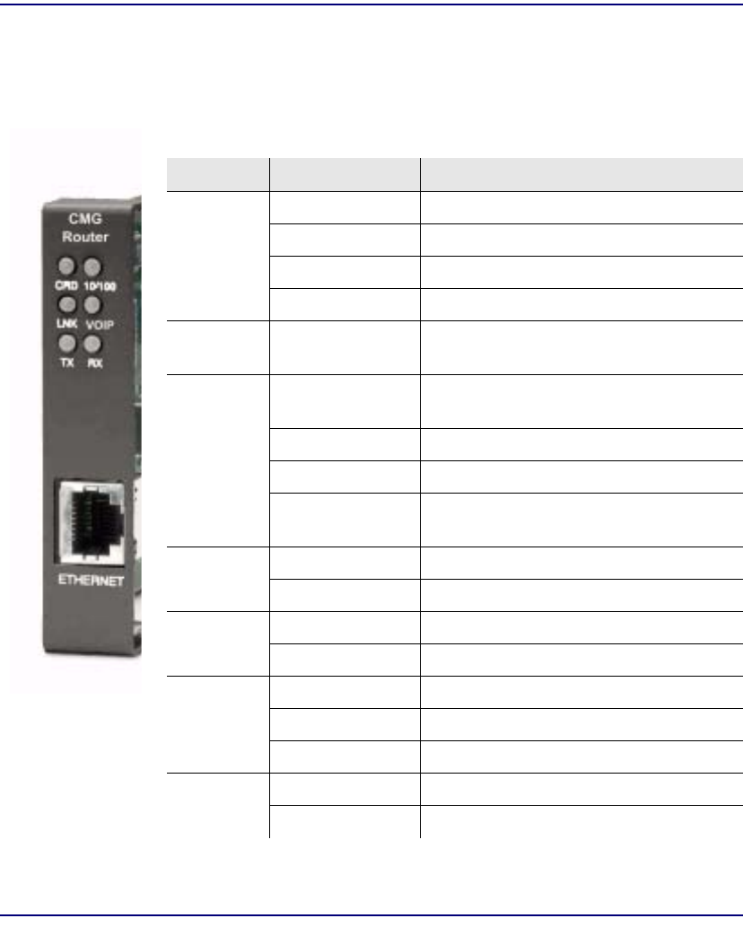
Compact T1 - Release 6.1 14-23
Router (CMG) Card
LEDs
LEDs
The following chart describes each LED, and it’s state, of the Router card.
LED State Description
CRD Off Loss of power
Green No current alarms
Red Alarm state active. See alarm log for cause
Red Flashing Self-test or Boot in-process
Yellow Flashing Card is saving data to flash RAM, do not
power down
VOIP
Off No active VoIP calls or if the MGCP
protocol is optioned down
Green Active VoIP calls
Red Call agent unreachable
Yellow Insufficient VoIP resources to complete
call
LNK Off No ethernet link
Green Good ethernet link
10/100 Off 10 Mb ethernet
Green 100 Mb ethernet
TX Off No ethernet transmit activity
Green Ethernet transmit activity
Yellow Current ethernet transmit collision
RX Off No current ethernet receive activity
Green Current ethernet receive activity

14-24 Compact T1 - Release 6.1
Router (CMG) Card
LEDs
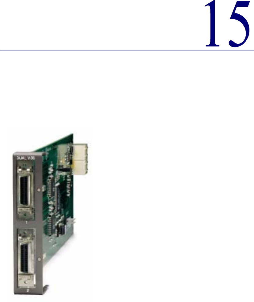
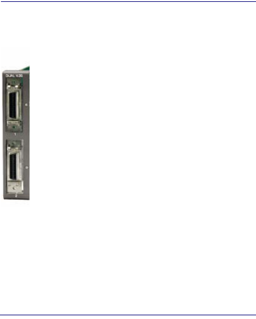
15-2 Compact T1 - Release 6.1
V.35/V.54 Cards
Overview
Overview
V.35 Service Card
The V.35 Service card enables service providers and enterprise network
managers to provision connectivity to high-speed serial synchronous Data
Terminal Equipment (DTE) devices such as routers, Frame Relay Access
Devices (FRAD) and video conferencing equipment.
The V.35 Service card provides scalable high-speed data service capacity to grow
with user needs. Up to six V.35 cards can be inserted into any slot of the Compact
T1 Customer Service Terminal, providing up to 12 fractional T1 V.35
connections from two T1 network connections. Two Adit Quad T1 Network
Access/Drop-and-Insert cards allow eight T1s with full T1 CSU/DSU
functionality to be terminated to eight V.35 ports in a single Compact T1. The
Adit’s digital cross-connect functionality offers service grooming, T1 drop-and-
insert, and voice access integration that are not available in traditional CSU/DSU
offerings.
Each V.35 port supports any n x 56/64 Kbps rate up to 1.536 Mbps. Both ports
may operate simultaneously at any supported speed. Flexible clocking allows
loop timing from any T1 line and provide system clocking to the connected DTE,
supporting a wide range of data networking applications.
Local and remote management options for the V.35 cards are available through
the Compact T1 Controller. The cards can be locally configured and managed
using CLI.
V.35/54 Service Card
Additionally, each V.35 port supports V.54 loopback test capabilities. This
feature enables V.54 loopback pattern recognition, generation and timing control
to troubleshoot service from the network or the end device to the V.35 electrical
interface. Four standard Bit Error Rate Test (BERT) patterns and an error counter
are provided for testing.

Compact T1 - Release 6.1 15-3
V.35/V.54 Cards
Features
Features
lProvides any n x 56/64 Kbps data rate up to 1.536 Mbps on each port
lSupports full non-blocking cross-connection of all timeslots to any T1 access line
lEnables up to 12 V.35 ports may be equipped in a single Compact T1
lAllows a total of 24 V.35 ports to be equipped in two Compact T1, occupying
only two rack units of equipment space in a 19-inch rack
lIncludes integration of T1 CSU/DSU functionality and remote management
capabilities
lSupports adaptation and transport over TDM facilities
lIntegrates frame relay or private line V.35 services with voice and Internet access
over T1 lines
Additional V.54 Features
lV.54 Loop Test capability
Technical Specifications
Controller Software Required
T1 Controller
lRelease 1.2.2 or higher is required for the V.35 card
lRelease 3.0 or higher is required for the V.35/V.54 card
Service Interface
lTwo V.35 interfaces:
-DCE to DTE pinout
-Two sub-miniature DB-26 connectors
-Adapters outlined below

15-4 Compact T1 - Release 6.1
V.35/V.54 Cards
Technical Specifications
Network Interface
lT1 TDM
Clocking
lLooped-timed from any T1 or ISDN BRI card installed
lSources clock to the DTE device
Testing and Diagnostics (V.35/54 card)
lAddressable V.54 loop up and loop down (127-code) pattern generation/
detection
l2047, 215-1, 220-1 and QRSS Test Patterns with error counter
Power
l2 W maximum
Regulatory Approvals
USA
lUL60950
lFCC Part 15, Class A
lNEBS Level 3 for type 2 and 4 equipment
GR-63-CORE, GR-1089-CORE
Canada
lCSA C22.2 No. 60950-00
lICES-003, Class A

Compact T1 - Release 6.1 15-5
V.35/V.54 Cards
Technical Specifications
Physical
lDimensions: 3.5 in. (H) x 0.75 in. (W) x 11.25 in. (D)
8.9 cm (H) x 1.9 cm (W) x 28.6 cm (D)
lWeight: 4.6 oz. (0.13 kg)
For information on Compact T1 Environment required, see Installation Environment
on page 2-2.
Accessories
Sub-miniature DB-26 to Winchester adapter cables are required to interface DTE with
the Dual V.35 card. Gender refers to the Winchester connector. One cable per port.
lP/N 005-0008 V.35 Male 10 Ft. (3.05 m) cable
lP/N 005-0009 V.35 Male 25 Ft. (7.62 m) cable
lP/N 005-0010 V.35 Male 50 Ft. (15.24 m) cable
lP/N 005-0011 V.35 Female 10 Ft. (3.05 m) cable

15-6 Compact T1 - Release 6.1
V.35/V.54 Cards
Card Configuration
Card Configuration
The V.35 Service cards can be configured, using the Command Line Interface (CLI).
CLI Commands
The following commands are used to configure the V.35 Service cards. For detailed
information on these commands, see Chapter 5, CLI Commands.
l connect
Creates two-way connections between channels.
l disconnect
Removes a connection created by the connect command.
l set (v35)
Setup of channels of a V.35 card (clock, clear to send, data, equipment, line,
receive clock invert, speed, transmit clock invert).
l set (v54)
Set the V.54 loopback test parameters.
l show (v35)
Displays the current settings for V.35 (clear to send, timing, Rx clock
inversion, Tx clock inversion, data inversion, data speed, data rate,
loopback)
l show (v54)
Displays the current settings for V.54 (CTS, timing, Rx clock inversion, Tx
clock inversion, data inversion, data speed, data rate, Rx LB, Rx Addr, test
address, Tx Prep count, Rx Prep count, test pattern, ignore ACK, loopback)
l status (v35)
Displays the current status of the specified V.35 (data terminal ready,
request to send, data carrier detect, clear to send, data set ready).
l status (v54)
Displays the current near-end line status of the specified V.54 (DCD, CTS,
DSR, RTS, DTR, BERT).
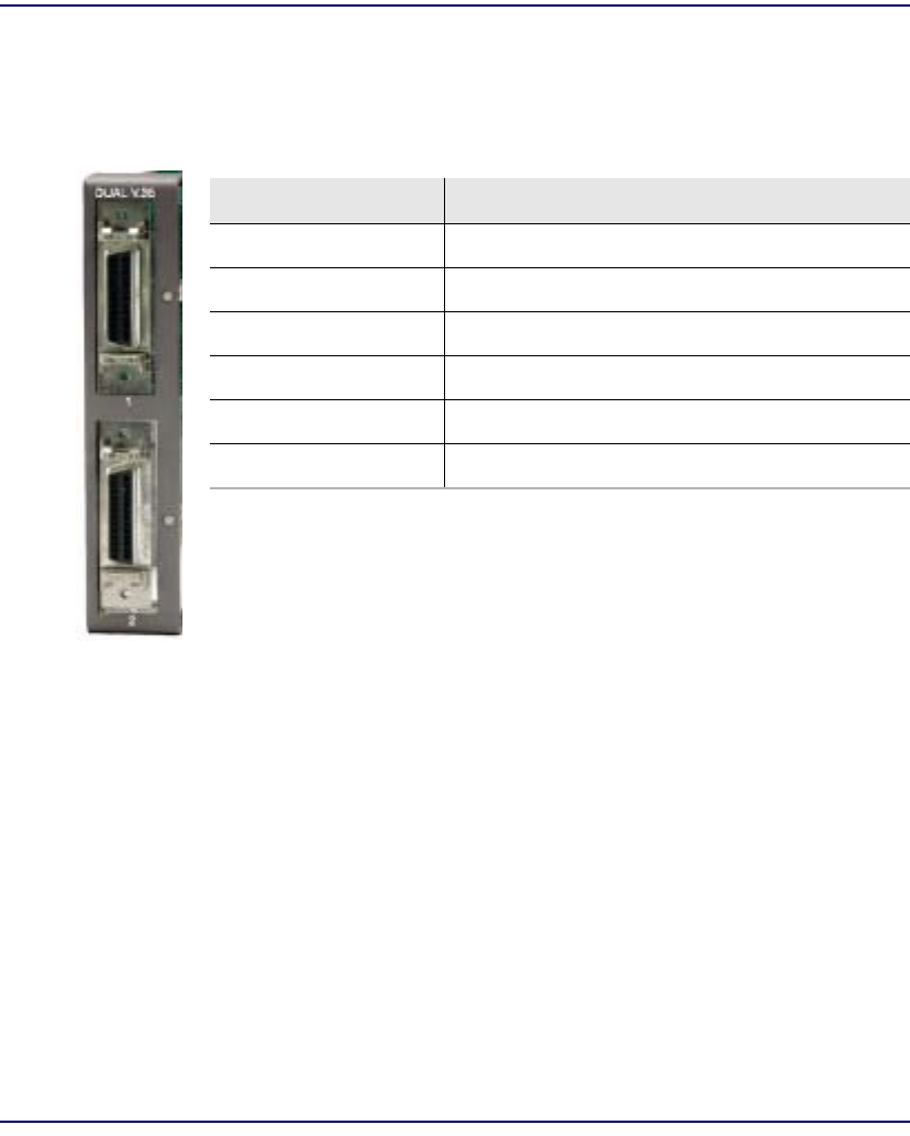
Compact T1 - Release 6.1 15-7
V.35/V.54 Cards
LEDs
LEDs
Each V.35 port has its own LED, as shown in the table below.
State Description
Off No T1 Assignment
Green Normal (CD/RTS) Active
Red CD inactive (T1-side failure)
Yellow RTS inactive (equipment-side failure)
Flashing Yellow Loopback toward T1 or equipment loop test
Flashing Green Loopback toward equipment or network loop test

15-8 Compact T1 - Release 6.1
V.35/V.54 Cards
Cables
Cables
Depending on your application, you will need to purchase one or more of the available
V.35 data cables:
These cables can be purchased at a licensed distributor.
Part Number Description Notes
005-0014 V.35 Female
10-foot cable These cables are used to provide the V.35 DCE
interface on a male connector to typical DTE
applications. Order one cable per V.35 port.
005-0068 V.35 Female
25-foot cable
005-0069 V.35 Female
50-foot cable
005-0010 V.35 Male
50-foot cable V.35 data cables with male connector for
connecting a router with a female V.35
Winchester connector or other data equipment to
a Compact T1 V.35 data port (sub-miniature DB-
26). Order one cable per V.35 port.
005-0009 V.35 Male
25-foot cable
005-0008 V.35 Male
10-foot cable
005-0189 DB-25 V.35 Female
50-foot cable These cables are used to provide a DB-25 DCE
V.35 female interface for connection to a male
DB-25 DTE V.35 interface. Order one per port.
005-0188 DB-25 V.35 Female
25-foot cable
005-0187 DB-25 V.35 Female
10-foot cable
005-0186 DB-25 V.35 Female
6-foot cable

Compact T1 - Release 6.1 15-9
V.35/V.54 Cards
Connector Pinouts
Connector Pinouts
V.35 DCE (DB-26)
The V.35 DCE data port connection is made at the sub-miniature DB-26 connector on
the Compact T1 using the 10-foot, 25-foot, or 50 foot DTE V.35 cable equipped with
a sub-miniature DB-26 connector and a 34-pin Winchester connector.
This cable is used to connect the Compact T1 V.35 DCE data ports to synchronous
V.35 DTE data sources up to 1.536 Mbps, all rates (1-24) Nx56 or Nx64 channel-rate
progression.
The V.35 data cables are built according to the pin assignments listed below:
Sub-miniature
DB-26 Signal Winchester 34-pin
(female) Paired
Signals
1 (+ Shield) ← Protective Ground →A]
7← Signal Ground →B
2← Transmit Data A P]
14 ← Transmit Data B S
3 Receive Data A →R]
16 Receive Data B →T
4← RTS C]
20 ← DTR H
5 CTS →D]
6 DSR →E
12 Test Mode →K]
8 CD (RLSD) →F
11 ← External Clock A U]
24 ← External Clock B W

15-10 Compact T1 - Release 6.1
V.35/V.54 Cards
Connector Pinouts
Sub-miniature
DB-26 Signal Winchester
34-pin (female) Paired
Signals
10 Xmit Clock A →Y]
23 Xmit Clock B →AA
15 Receive Clock A →V]
17 Receive Clock B →X
22 ← Local Loopback J]
25 ← Remote Loopback BB
9, 13, 18 Open Pins/No Contact L, N, NN
19, 21, 26 Open Pins/No Contact

CHAPTER
Maintenance
In this Chapter
nSoftware Upgrade
-Minimum Version Levels
-Determining Boot Code Software Level
-Upgrading System and Router Software via TFTP
-Upgrading System and Router Software via TFTP using Proxy
-Upgrading Software Levels via X-Modem
nBackup Controller Configuration
-Save Controller Configuration
-Load Controller Configuration
nReplace Controller Card
nHot Swap Service Card

16-2 Compact T1 - Release 6.1
Maintenance
Software Upgrade
Software Upgrade
Minimum Version Levels
Before starting a software upgrade, you must ensure that the Commpact T1 unit has the
correct software and hardware versions. The first set of instructions below show how
to determine the boot software version level in the unit. This is the simplest way to
confirm these versions.
Determining Boot Code Software Level
1. Start a CLI session on the Commpact T1 using a terminal emulation program
or via Telnet.
2. After login, type status equipment at the CLI prompt.
A message similar to the following should appear:
> status equipment
BootCode Version: 1.18
CardType Status SW Vers
-------- ------ -------
SLOT A T1x2 Present 1.4
SLOT 1 FXSx8 Not resent
SLOT 2 FXSx8 Present 1.09
SLOT 3 T1x4 Present 1.36
SLOT 4 BRIx4 Present 1.00
SLOT 5 T1x4 Present 1.36
SLOT 6 FXSx8 Present 1.09
The BootCode Version must be at least 1.04. If it is less, contact Customer Servicce for
a required hardware upgrade.

Compact T1 - Release 6.1 16-3
Maintenance
Software Upgrade
Upgrading System and Router Software via TFTP
1. Login to the Commpact T1, using a terminal emulation program or via Telnet.
2. Enter: load [slot] tftp {ip-addr} "file-name"
where [slot] = the slot number of a router card. If no slot number is listed, the
file is loaded to the Controller.
{ip-addr} = the IP address of the host device holding the downloadable
software
"file-name" = the software file name, including path, if needed. Enclosed in
quotes. Example: "c:\unit_sw\tdm4_0_z_all.mgm".
This example loads tdm4_0_z_all.mgm via tftp from the C drive and unit_sw
subdirectory. The path information must be provided.
The tftp utility provideds with the downloadble software must also be running,
in the same directory as the software file.
3. After download, the program will be loaded from RAM into the flash memory
and the system will automatically restart. Wait until the boot menu prompt is
displayed before powering down the unit. If the download fails and no prompt
is seen after a full minute, cycle power and repeat the process.
4. Re-establish communication with the CLI using a terminal emulation program
or Telnet. Check all configurations and system operation.

16-4 Compact T1 - Release 6.1
Maintenance
Software Upgrade
Upgrading System and Router Software via TFTP using
Proxy
Required: - Router Service card (IP or CMG) release 1.32 or higher
- Controller software 3.2 or higher
- Ethernet cable connected to port on front of Router card
1. Set up the Proxy with the following commands
set ethernet ip address {ip-addr} [mask]
set {rtr_lan-addr} ip address {ip-addr} [mask]
set {rtr_card-addr} proxy enable {ip-addr} [mask]
set ip gateway {ip-addr}
Example: (example with router in slot 3)
set ethernet ip address 10.0.0.1 255.0.0.0
set 3:1 ip address 192.168.100.1/24
set 3 proxy enable 192.168.100.80/24
set ip gateway 192.168.100.80
NOTE: See Chapter 5,CLI Commands for more information on these
commands.
1. Login to the Compact T1 using the Proxy IP address, (example:
192.168.100.80) using a terminal emulation program or via Telnet.
2. Enter: load [slot] tftp {ip-addr} "file-name"
where [slot] = the slot number of a router card. If no slot number is listed, the
file is loaded to the Controller.
{ip-addr} = the IP address of the host device holding the downloadable
software
"file-name" = the software file name, including path, if needed. Enclosed in
quotes. Example: "c:\unit_sw\tdm4_0_z_all.mgm".
This example loads tdm4_0_z_all.mgm via tftp from the C drive and unit_sw
subdirectory. The path information must be provided.
The tftp utility provided with the downloadble software must also be running,
in the same directory as the software file.

Compact T1 - Release 6.1 16-5
Maintenance
Software Upgrade
3. After download, the program will be loaded from RAM into the flash memory
and the system will automatically restart. Wait until the boot menu prompt is
displayed before powering down the unit. If the download fails and no prompt
is seen after a full minute, cycle power and repeat the process.
4. Re-establish communication with the CLI using a terminal emulation program
or Telnet. Check all configurations and system operation.

16-6 Compact T1 - Release 6.1
Maintenance
Software Upgrade
Upgrading Software Levels via X-Modem
1. Login to the Compact T1.
2. Enter: load xmodem to download the application from the binary file. This
will start the system looking for an xmodem download. The Commpact T1 will
prompt you to send the file. Use one of the following methods:
Using HyperTerminal
lPull down the Transfer menu
lSelect Send File Provide the filename (and path if required), confirm
that the xmodem protocol is used for the transfer, and start the
download with the Send button
lA window will show the progress of the download.
Using Procomm
lPull down the File menu
lSelect Connection Directory
lUnder the Data tab, use the Basic Options button to confirm that the
xmodem protocol is used for file transfers
lPull down the Data menu, select Send File, provide the filename, and
start the download
Another Terminal Emulation Program
When using another terminal emulation program, confirm the use of xmodem
protocol at 9600 baud, provide filename (and path) and initiate the download.
3. The binary file name is usually in the format: Adit.pkt. At 9600 baud, the file
transfer will take approximately 20 minutes.
4. After download, the program will be loaded from RAM into the flash memory
and the system will automatically restart. Wait until the boot menu prompt is
displayed before powering down the unit. If the download fails and no prompt
is seen after a full minute, cycle power and repeat the process.
5. Re-establish communication with the CLI using a terminal emulation program.
Check all configurations and system operation.

Compact T1 - Release 6.1 16-7
Maintenance
Backup Controller Configuration
Backup Controller Configuration
A text file from the current configuration can be generated to reload the in the event the
configuration has been lost due to card or software problems. The download of the file,
generated by the print config command, can be done by direct connect to the
RS-232 port or via Telnet. The upload of the file from the PC back to theController can
only be done via direct RS-232 connection. This is because the Controller will be at
factory default and an IP address is not assigned to the Unit.
Save Controller Configuration
The following example is shown with a HyperTerm session, with Telnet selections in
parenthesis, other programs may be used and the process is similar, however the menu
selections may be different.
1. Start a HyperTerm session to an Commpact T1.
2. Type the CLI command print config and do not hit [ENTER].
3. Type select Transfer/Capture Text from the drop-down menu.
(Telnet - Terminal/Start Logging)
4. Name the file, select OK.
5. Return to the CLI command print config and hit [ENTER].
This process will exclude the print config command itself, from the
configuration file you are creating.
6. (Telnet - Select Terminal/Stop Logging).
7. Save configuration file as a .txt file, if necessary (Telnet will create a .log file,
which will need to be "saved as" a .txt file).
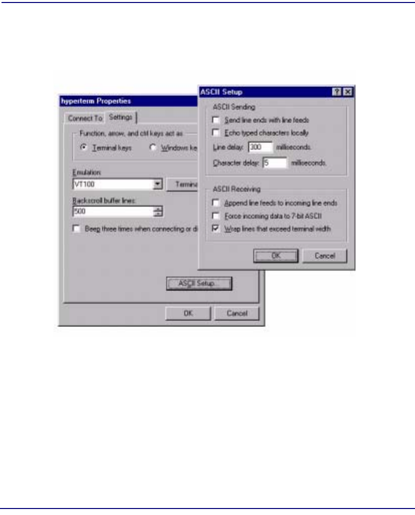
16-8 Compact T1 - Release 6.1
Maintenance
Backup Controller Configuration
Load Controller Configuration
1. Open HyperTerm session with the Commpact T1 unit.
2. In HyperTerm, select File/Properties/Settings/ASCII Setup.
3. Set the Line delay to 300 ms and the Character delay to 5 ms.
4. Select OK to save ASCII Setup and OK to save HyperTerm Properties.
5. Select Transfer/Send Text File.
6. Select .txt file from previous steps.
7. Click Open.
8. Configuration will load.

Compact T1 - Release 6.1 16-9
Maintenance
Replace Controller Card
Replace Controller Card
WARNING! SERVICE WILL BE INTERRUPTED WITH THE PROCESS OF
CHANGING OUT A CONTROLLER CARD.
It is not necessary to power down a unit to replace a Controller, however if you would
like to load the configuration file to the new Controller card you must backup the
configuration file before this process.
1. Backup Controller Configuration, see Save Controller Configuration on page
16-7.
2. Remove Controller card, gently slide the Service card straight out of the slot.
3. Replace Controller card, gently slide the new Service card into the empty slot.
4. Ensure that the new card is seated firmly into the connector at the back of the
unit.
5. Load Controller Configuration, see Load Controller Configuration on page
16-8
Hot Swap Service Card
To Hot-Swap (replace) a service card while the unit is powered on, follow the steps
below:
1. Gently slide the Service card straight out of the slot.
2. Gently slide the new Service card into the empty slot.
3. Ensure that the new card is fastened securely into the connector at the back of
the unit.

16-10 Compact T1 - Release 6.1
Maintenance
Hot Swap Service Card


A-2 Compact T1 - Release 6.0
SNMP Interface
Overview
Overview
The Simple Network Management Protocol (SNMP) enables network operations
centers (NOCs) to monitor and manage network elements across an internetwork. The
Commpact T1 supports SNMP through its Ethernet port, which provides access to the
carrier’s TCP/IP management network.
SNMP Basics
SNMP is a mechanism for managing TCP/IP networks. It works by exchanging
information between an SNMP Manager and an SNMP Agent.
MIB Structure
The SNMP Agent displays network information in a Management Information Base
(MIB). MIBs are machine-to-machine interfaces that arrange and present information
according to industry standards such as RFC 1213. MIBs are tree-like structures
comprising nodes and leaves. Nodes are branch points used to divide information into
categories. Leaves have object values that can be examined and changed. Common
MIB objects include system names, performance statistics, and control values.
Control values are typically Integer types. This enables the object’s value to represent
a specific control selection. Selections are usually written in the “name(value)” format.
For example, the selection “closed(1)” means that the “closed” state is indicated by a
value of “1”.

Compact T1 - Release 6.0 A-3
SNMP Interface
Enterprise MIB Support
Enterprise MIB Support
This release is with full SNMPv1 and SNMPv2c support. Enterprise MIBs are defined
using only SMIv2 (as noted in the table).
Enterprise MIB Name Enterprise MIB Filename
CARRIERACCESS-GENERIC- MIB carrieraccess-generic.mib
CARRIERACCESS-TC-MIB carrieraccess-tc.mib
CAGEN-GENERIC-MIB cagen-generic.mib
CAGEN-SLOT-MIB cagen-slot.mib
CAGEN-SYSTEM-MIB cagen-system.mib
ADIT600-SYSTEM-MIB adit600-system.mib
CAGEN-ALARM-MIB cagen-alarm.mib
CAGEN-EVENT-MIB cagen-event.mib
CAGEN-TRAPS-MIB cagen-traps.mib
CAGEN-DS0-MIB cagen-ds0.mib
CAGEN-DS1-MIB cagen-ds1.mib
ADIT600-DS1-MIB adit600-ds1.mib
ADIT600-TDM-DS1-MIB adit600-tdm-ds1.mib
CAGEN-FX-MIB cagen-fx.mib
ADIT600-FX-MIB adit600-fx.mib
CAGEN-V35-MIB cagen-v35.mib
CAGEN-RS232-MIB cagen-rs232.mib
CAGEN-BRI-MIB cagen-bri.mib
ADIT600-TDM-ROUTER-MIB adit600-tdm-router.mib
CAGEN-PPHONE-MIB cagen-pphone.mib
CAGEN-OCUDP-MIB cagen-ocudp.mib
CAGEN-IF-FACTORY-MIB cagen-if-factory.mib

A-4 Compact T1 - Release 6.0
SNMP Interface
Router Enterprise MIB Support
Router Enterprise MIB Support
CAGEN-NTP-MIB cagen-ntp.mib
CAGEN-SYSLOG-MIB cagen-syslog.mib
ADIT600-TDM-CMG-MIB adit600-tdm-cmg.mib
CAGEN-CMG-MIB cagen-cmg.mib
ADIT600-TDM-DEPRECIATED-OIDS-MIB adit600-tdm-depreciated-oids.mib
SNMPV2-CONF-MIB snmpv2-conf.mib
SNMPV2-SMI-MIB snmpv2-smi.mib
SNMPV2-TC-MIB snmpv2-tc.mib
Enterprise MIB Name Enterprise MIB Filename
Router Specific
CAGENROUTER-MIB caGenRouter.mib
CAGENROUTER-CARDPROFILE-MIB caGenRouter-CardProfile.mib
CAGENROUTER-DNS-MIB caGenRouter-DNS.mib
CAGENROUTER-FILTERS-MIB caGenRouter-Filters.mib
CAGENROUTER-LANPROFILE-MIB caGenRouter-LanProfile.mib
CAGENROUTER-MANAGEMENT-MIB CAGenRouter-Mgt.mib
CAGENROUTER-NTTPPROFILE-MIB caGenRouter-NTPProfile.mib
CAGENROUTER-REPORTS-MIB caGenRouter-Reports.mib
CAGENROUTER-SPANTREE-MIB caGenRouter-SpanTree.mib
CAGENROUTER-STATIC-MIB DEFINITIONS caGenRouter-Static.mib
CAGENROUTER-TC-MIB caGenRouter-tc.mib
CAGENROUTER-TRUNK-MIB caGenRouter-trunk.mib
CAGENROUTER-WANPROFILE-MIB caGenRouter-WanProfile.mib

Compact T1 - Release 6.0 A-5
SNMP Interface
Router Enterprise MIB Support
CMG Specific
ADIT-CMG-MIB adit-cmg.mib
ADITCMG-CARD-MIB adit-cmg-card.mib
ADITGENCMG-ALGO-MIB aditGenCmg-algo.mib
ADITGENCMG-MGCP-MIB aditGenCmg-mgcp.mib
ADITGENCMGCARD-TC-MIB aditGenCmg-tc.mib
ADITGENCMG-TRUNK-MIB aditGenCmg-trunk.mib
ADITGENCMG-VCHAN-MIB aditGenCmg-vchan.mib
ADITGENCMG-VOIP-MIB aditGenCmg-voip.mib
Common with Controller
CARRIERACCESS-GENERIC-MIB carrieraccess-generic.mib
CARRIERACCESS-TC-MIB carrieraccess-tc.mib
CAGEN-GENERIC-MIB cagen-generic.mib
CAGEN-SYSTEM-MIB cagen-system.mib

A-6 Compact T1 - Release 6.0
SNMP Interface
Public MIB Support
Public MIB Support
MIB Table Comments
RFC1155 (RFC-1155-SMI-MIB)
RFC1212 (RFC-1212-MIB)
RFC1213 (RFC-1213-MIB) system tcp
interfaces udp
ip snmp
icmp
egp not supported
RFC1215 (RFC-1215-MIB)
RFC1215-TRAP
(RFC-1215-TRAP-MIB)
RFC1659 (RFC1659-MIB) rs232PortTable
rs232SyncPortTable
rs232InSigTable
rs232OutSigTable
Supports V.35 Card
Rs232AsnycPortTable
not supported
RFC1907 (SNMPv2-MIB) system
sysORTable
snmp
SMIv2 Extension of
RFC1213
RFC2011 (IP-MIB) ip
ipAddrTable
ipNetToMediaTable
icmp
SMIv2 Extension of
RFC1213
RFC2233 (IF-MIB) ifTable
ifXTable
ifStackTable
IfTestTable,
ifRcvAddressTable not
supported
IANAifType-MIB IANAifType Used by RFC2233; no
objects
RFC2493 (PerHist-TC-MIB) Performance History TC Defines textual
conventions; no objects
RFC2494 (DS0-MIB,
DS0BUNDLE-MIB) dsx0ConfigTable
dsx0ChanMappingTable
dsx0BundleTable
Dsx0BondingTable not
supported

Compact T1 - Release 6.0 A-7
SNMP Interface
Router Public MIB Support
Router Public MIB Support
RFC2495 (DS1-MIB) dsx1ConfigTable
dsx1CurrentTable
dsx1IntervalTable
dsx1TotalTable
Far End Tables and
Fractional Table not
supported
RFC2571 (SNMP-
FRAMEWORK-MIB) SNMP TC Defines textual
conventions1 no objects
MIB Table Comments
RFC1213 (RFC-1213-MIB) system
interfaces
ip
icmp
tcp
udp
snmp
egp not supported
RFC1907 (SNMPv2-MIB) system
snmp SMIv2 Extension of RFC1213
SysORTable not supported
RFC2011 (IP-MIB) ip
icmp SMIv2 Extension of RFC1213.
IpAddrTable not supported.
Routing table and
ipNetToMediaTable supported
by Enterprise mibs.
RFC2233 (IF-MIB) ifTable IfTestTable, ifRcvAddressTable,
ifXTable, ifStackTable not
supported
RFC3291(RFC-3291-MIB)
IANAifType-MIB IANAifType Used by RFC2233; no objects

A-8 Compact T1 - Release 6.0
SNMP Interface
SNMP Trap Reports
SNMP Trap Reports
The Commpact T1 can send the following SNMP trap reports.
Standard Traps
Trap Description Test Method
authenticationFailure Occurs when a bad community string is
used. Attempt a Get or Set
using an invalid
community string.
linkDown Sent when a DS1 changes from an up (in-
service) state to a down (out-of-service)
state. It is not sent when a DS1 is set
“down” by a manual command.
Also sent when a DS1 is set up manually, if
it is in an out-of-service state.
Disconnect an in-service
DS1.
linkUp Sent when a DS1 changes from a down
(out-of-service) state to an up (in-service)
state. It is not sent when a DS1 is set “up”
by a manual command.
Connect a DS1 and put it
into service.
coldStart Sent whenever the SNMP agent is restarted
as a result of a software reset or unit power-
up.
Cycle the power off and
on.

Compact T1 - Release 6.0 A-9
SNMP Interface
SNMP Trap Reports
Enterprise Traps
Trap Description Test Method
caGenEventLogTrap This trap is generated when an event has
been logged into the device’s Event Log.
This trap contains 5 mandatory variable
bindings and may contain up to 3 optional
variable bindings. The mandatory variable
bindings are caGenEventLogIndex,
caGenEventSeverity, caGenEventCategory,
caGenEventCode, and caGenEventDate.
The optional variable bindings are
caGenEventInfoParam1,
caGenEventInfoParam2 and
caGenEventAdditionalText. The optional
variable bindings (if present) will always
appear at the end of the variable binding list.

A-10 Compact T1 - Release 6.0
SNMP Interface
SNMP Trap Reports

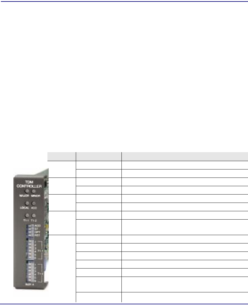
B-2 Compact T1 - Release 6.1
Diagnostices & Troubleshooting
Alarms
Alarms
Test Alarm
The Commpact T1 alarm functions can be manually tested using the following
command for setting critical, major and minor alarms. Turning alarms on or off will
produce alarm messages and log entries stating the alarm event was manually set/
cleared by the user.
Syntax: set alarms {critical|major|minor} {off|on}
Identify Alarm
Alarm indicators
l LEDs - When an Alarm is triggered, the LED (labeled CRD) will display a
red indicator light, which will stay on until the Alarm is cleared. The
following is the LED information for the T1 Controller card. For LED
infomation for the specific service card see the chapter for that card.
LED State Description
MAJOR Off No major alarms present
Red Major alarm present
MINOR Off No minor alarms present
Yellow Minor alarms present
LOCAL Off Remote mode (DIP switches disabled)
Green Local mode (DIP switches enabled)
ACO Off Normal mode. No alarms are being suppressed.
Yellow Alarm cutoff active. One or more active alarms
suppressed.
T1-1 and
T1-2 Off Off line
Green Normal
Red Loss of Signal (LOS) detected
Yellow Bipolar Violation (BPV) detected
Flashing Green Loopback active
Flashing Red Loss of Frame (LOF) or Alarm Indication Signal
(AIS) detected
Flashing Yellow Yellow alarm (Remote Alarm Indication) detected.

Compact T1 - Release 6.1 B-3
Diagnostices & Troubleshooting
Alarms
The following are hyperlinks to all the card LED information:
T1 Controller Card, LEDs
FXO Voice Card, LEDs
FXS Voice Card, LEDs
ISDN BRI Card, LEDs
OCU-DP Card, LEDs
Single Channel POTS Card, LEDs
Router (IP) Card, LEDs
Router (CMG) Card, LEDs
Terminal Server Router Card, LEDs
V.35/V.54 Cards, LEDs
Power Supply, 115 VAC LEDs

B-4 Compact T1 - Release 6.1
Diagnostices & Troubleshooting
Alarms
Display Alarms
Use the alarms command to display the active alarms. Each alarm is related to a
particular address and has a severity category (major, minor, critical, alert). The
report can be filtered by port address and/or severity.
Syntax: alarms [slot|slot:port|slot:port:channel] [category]
[severity]
> alarms
Time Date Severity Description
07:35:45 01/04/2002 Major Test Major Alarm
07:35:21 01/04/2002 Minor Test Minor Alarm
07:34:57 01/04/2002 Critical Test Critical Alarm
07:30:39 01/04/2002 Major 1:1-OCUDP Out of Service
03:50:55 01/04/2002 Major 1:1-OCUDP Loss of Signal
00:00:20 01/01/2002 Major 4:1-CMG Ethernet Link Down
00:00:20 01/01/2002 Major 5:1-RTR Ethernet Link Down
00:00:05 01/01/2002 Major A:2-DS1 Loss Of Signal
00:00:05 01/01/2002 Major A:1-DS1 Loss Of Signal
Total=10
Category = bri|ds1|env|equipment|fxo|fxs|rtr|v35
Severity = alert|critical|info|major|minor
Clear Alarm
Once an alarm is identified then the process of clearing it can begin.
l Silence Alarm, if necessary (Alarm Cut Off CLI command: aco)
l Check Connection
l Check Cable, replace if necessary
l Check hardware and replace if necessary
l Call Customer Service

Compact T1 - Release 6.1 B-5
Diagnostices & Troubleshooting
Logs
Logs
Display the event log to view a log of all system events, or narrow the view to only
display specific information.
Syntax: log [slot|slot:port] [category] [severity]
Example: log
Time Date Severity Description
00:00:15 01/01/2002 Major 4:1-CMG Ethernet Link Down
00:00:12 01/01/2002 Info 3-FXOx8 Card Detected
00:00:12 01/01/2002 Info 2-FXS5Gx8 Card Detected
00:00:06 01/01/2002 Major A:2-DS1 Loss Of Signal
00:00:05 01/01/2002 Info 4-CMGx1 Card Detected
00:00:02 01/01/2002 Info A-T1x2 Card Detected
00:00:02 01/01/2002 Info System Powerup
Total=7
Category = bri|ds1|env|equipment|fxo|fxs|rtr|v35
Severity = alert|critical|info|major|minor

B-6 Compact T1 - Release 6.1
Diagnostices & Troubleshooting
Status and Performance
Status and Performance
The following status commands will display vital infomation regarding the system that
will aid in troubleshooting. All commands listed below are hyperlinked to the CLI
command.
status (bri) status (router) events
status clock status (router) ip address table
status (ds0) status (router) ip network table
status (ds1) status (router) ipx network table
status equipment status (router) ipx server table
status equipment status (router) log
status (fxo) status (router) mac address table
status (fxs5G) status (router) mgcp
status ipds0 status (router) performance
status (ocudp) status (router) stp
status (ocudp) performance status (router-lan)
status (ocudp) performance history status (router-trunk)
status (router) status (router-voice)
status (router) alarms status sessions
status (router) channels status (v35)
status (router) dns status (v54)

Compact T1 - Release 6.1 B-7
Diagnostices & Troubleshooting
Loopbacks Overview
Loopbacks Overview
A loopback test is a diagnostic procedure in which a signal is transmitted and returned
to the sending device after passing through all or a portion of a network or circuit. The
returned signal is compared with the transmitted signal in order to evaluate the integrity
of the equipment or transmission path. The following are the Loopbacks available.
T1 Loopbacks
OCU-DP Loopbacks
lManual OCU Loopback
lManual CSU Loopback
lOCU Latching Loopback
lCSU Latching Loopback
lDSU Latching Loopback
lDSU Non-Latching Loopback
lCSU Non-Latching Loopback
lOCU Non-Latching Loopback
lOCU Manual Loopback
lCSU Manual Loopback
Card Line Equipment Payload CSU
Controller T1 Yes No Yes Yes
Quad T1 Yes Yes Yes Yes
V.35 T1 Yes Yes No No
V.54 T1 Yes Yes No No
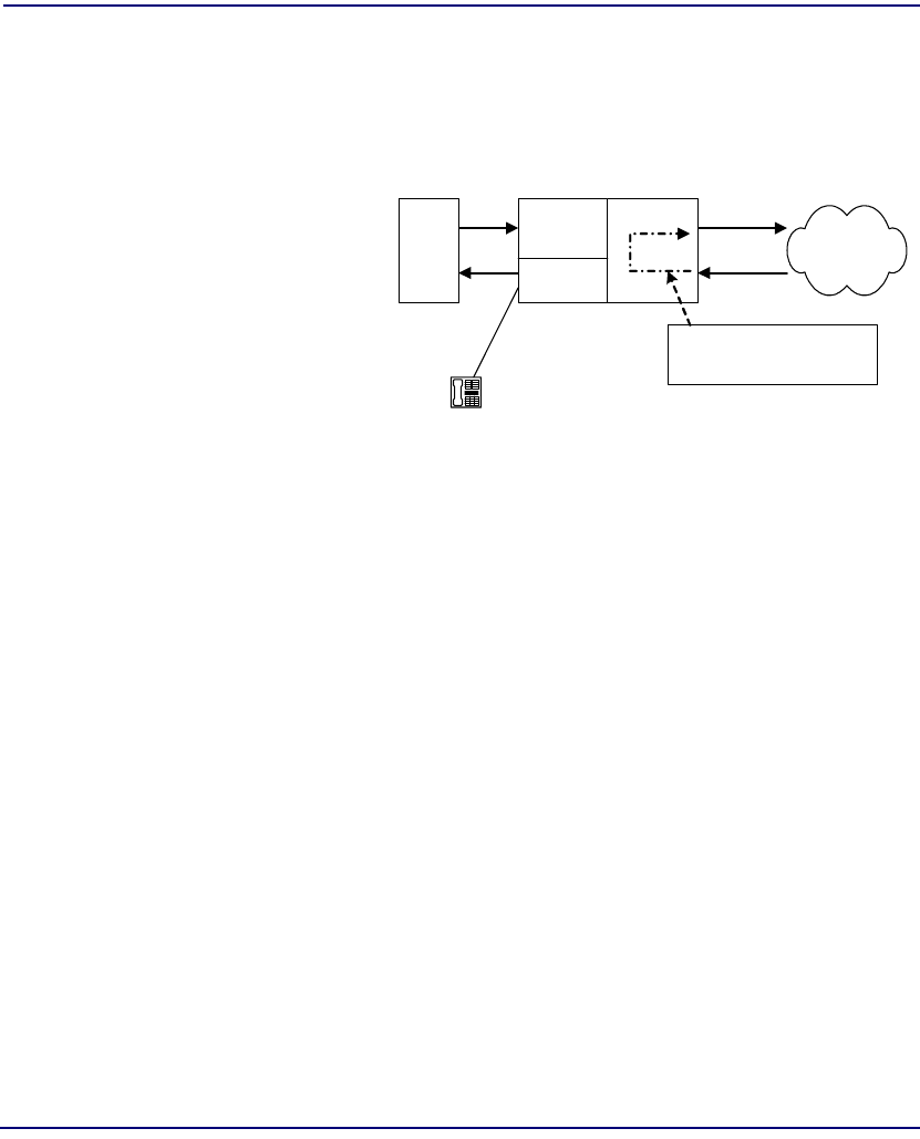
B-8 Compact T1 - Release 6.1
Diagnostices & Troubleshooting
Loopbacks Overview
DS1 Loopbacks
Note: T1 LEDs flash green during any DS1 loopback.
DS1 Line Loop
Loops at DS1 (at framer),
signal not reframed. Have
DS1 vendor check for
framing/errors.
Enable Line Loopback
> set a:1 line loopup
OK
View Status of Loopback
DS1 Status
> status a:1
SLOT A:
Status for DS1 1:
Receive: Traffic
Transmit: Traffic
Loopback: LINE
Disable Line Loopback
> set a:1 line loopdown
OK
View Status of Loopback
DS1 Status
> status a:1
SLOT A:
Status for DS1 1:
Receive: Traffic
Transmit: Traffic
Loopback: OFF
T1
Adit 600
Local
DCE
V.35
Loops DS1 as shown
Signal Not Reframed
Local
DTE
FXS
Telephone
DS1
Network
Compact T1
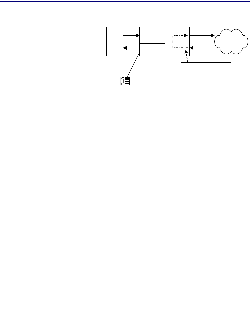
Compact T1 - Release 6.1 B-9
Diagnostices & Troubleshooting
Loopbacks Overview
DS1 Payload Loop
Loops at DS1 (in framer)
and reframes the T1.
Have DS1 vendor check
for framing/errors.
Enable Payload Loopback
> set a:1 payload loopup
OK
View Status of Loopback
> status a:1
SLOT A:
Status for DS1 1:
Receive: Traffic
Transmit: Traffic
Loopback: PAYLOAD
Disable Payload Loopback
> set a:1 payload loopdown
OK
View Status of Loopback
> status a:1
SLOT A:
Status for DS1 1:
Receive: Traffic
Transmit: Traffic
Loopback: OFF
T1
Adit 600
Local
DCE
V.35
Loops DS1 as shown
Reframes the T1
Local
DTE
FXS
Telephone
DS1
Network
Compact T1
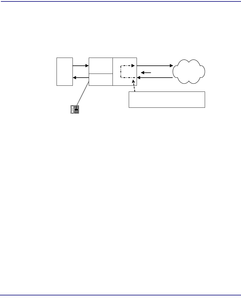
B-10 Compact T1 - Release 6.1
Diagnostices & Troubleshooting
Loopbacks Overview
Receiving DS1 CSU Loop
Causes a line Loopback. Loopup code sent by remote unit or network. Occurs at
local DS1 CSU. Have DS1 vendor check for framing/errors.
Enable Detection of CSU Loopcode
Enable detection of CSU loop code (10000 for loopup; 100 for loopdown).
> set a:1 loopdetect on
OK
View Status of Loopback
> show a:1
SLOT A:
Settings for DS1 1:
Circuit ID: DS1# A:1
Up/Down: UP
Framing: ESF
Line Coding: B8ZS
Line Build Out: DSX-1 EQUALIZATION FOR 0-133 ft.
(CSU 0dB)
Loop Code Detection: ON (Default)
Loopback: OFF
FDL Type: None
T1
Adit 600
Local
DCE
V.35
Loopup Code Sent by Remote Unit
Signal Not Reframed
Local
DTE
FXS
Telephone
DS1
Network
CSU Loopup
Code
Compact T1

Compact T1 - Release 6.1 B-11
Diagnostices & Troubleshooting
Loopbacks Overview
Performance Threshold Settings 15 min. 1 day
unavailable seconds: 0 0
severely errored seconds: 0 0
errored seconds: 0 0
sev. errored frame seconds: 0 0
line errored seconds: 0 0
controlled slip seconds: 0 0
bursty errored seconds: 0 0
degraded minutes: 0 0
total linecode violations: 0 0
total pathcode violations: 0 0
> status a:1
SLOT A:
Status for DS1 1:
Receive: Traffic
Transmit: Traffic
Loopback: LINE
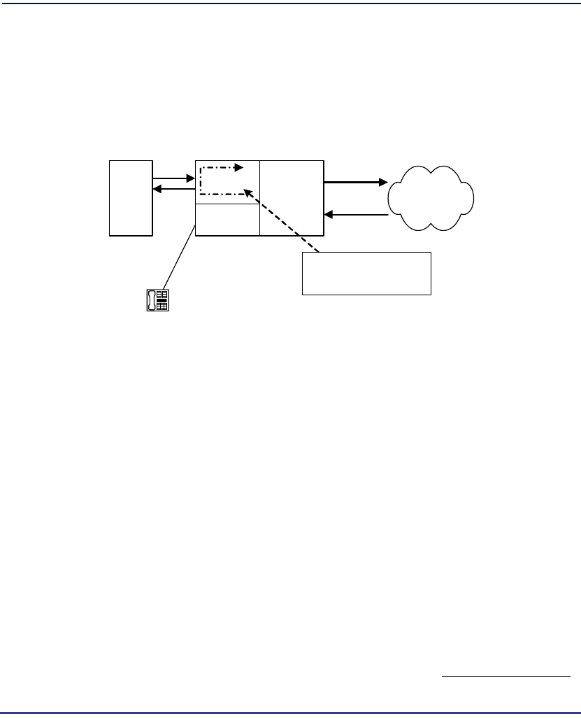
B-12 Compact T1 - Release 6.1
Diagnostices & Troubleshooting
Loopbacks Overview
DS1 Equipment Loop
Note: Quad T1 LED stays green during equipment loop. The DS1 Equipment
Loopback is available on the Quad T1 card and is not available on the Controller
card.
Enable Equipment Loopback
Where a Quad T1 card is in slot 5.
> set 5:1 equipment loopup
OK
View Status of Loopback
> show 5:1
SLOT 5:
Settings for DS1 1:
Circuit ID: DS1# 5:1
Up/Down: UP
Framing: ESF
Line Coding: B8ZS
Line Build Out: DSX-1 EQUALIZATION FOR 0-133 ft.
(CSU 0dB)
Loop Code Detection: ON
Loopback: EQUIPMENT
FDL Type: None
Performance Threshold Settings 15 min. 1 day
T1
Adit 600
Quad T1
Loops at local Quad
T1 port (location)
PBX
FXS
Telephone
DS1
Network
Compact T1

Compact T1 - Release 6.1 B-13
Diagnostices & Troubleshooting
Loopbacks Overview
unavailable seconds: 0 0
severely errored seconds: 0 0
errored seconds: 0 0
sev. errored frame seconds: 0 0
line errored seconds: 0 0
controlled slip seconds: 0 0
bursty errored seconds: 0 0
degraded minutes: 0 0
total linecode violations: 0 0
total pathcode violations: 0 0
Disable Equipment Loopback
> set 5:1 equipment loopdown
OK
View Status of Loopback
> show 5:1
SLOT 5:
Settings for DS1 1:
Circuit ID: DS1# 5:1
Up/Down: UP
Framing: ESF
Line Coding: B8ZS
Line Build Out: DSX-1 EQUALIZATION FOR 0-133 ft.
(CSU 0dB)
Loop Code Detection: ON
Loopback: OFF
FDL Type: None
Performance Threshold Settings 15 min. 1 day
unavailable seconds: 0 0
severely errored seconds: 0 0
errored seconds: 0 0
sev. errored frame seconds: 0 0
line errored seconds: 0 0
controlled slip seconds: 0 0
bursty errored seconds: 0 0
degraded minutes: 0 0
total linecode violations: 0 0
total pathcode violations: 0 0
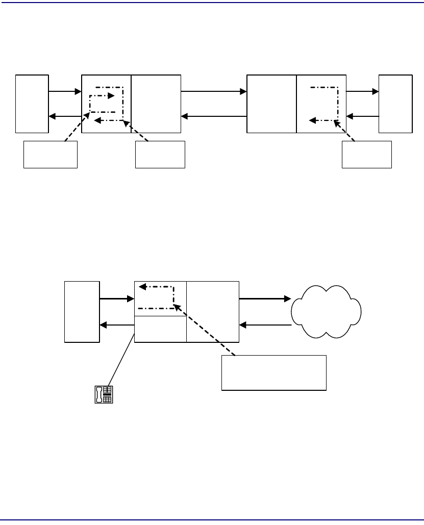
B-14 Compact T1 - Release 6.1
Diagnostices & Troubleshooting
Loopbacks Overview
V.35 Loopbacks
V.35 Line Loop
Note: V.35 LED flashes green during line loop.
Loop occurs at V.35 port. Check for sync and errors at local data port.
Enable Line Loopback
Where a V.35 card is in slot 6.
> set 6:1 line loopup
OK
T1
Network
T1
Local
DTE
Adit 600
Equipment
Unit
Local
DCE
V.35
Line
Loopback
Adit 600
Network
Unit
Remote
DTE
Remote
DCE
V.54
Loopback
V.35
Equipment
Loopback
Compact T1
Network
Unit
Compact T1
Equipment
Unit
T1
Adit 600
Local
DCE
V.35
Loop occurs at V.35
port (location)
Local
DTE
FXS
Tele
p
hone
DS1
Network
Compact T1

Compact T1 - Release 6.1 B-15
Diagnostices & Troubleshooting
Loopbacks Overview
View Status of Loopback
> show 6:1
SLOT 6:
Settings for V35 Port 1:
CTS: Always High
Timing: Source
Rx Clock Inversion: Normal
Tx Clock Inversion: Normal
Data Inversion: Normal
Data Speed: 64K
Data Rate: 1536 K
Loopback: Line
Disable Line Loopback
> set 6:1 line loopdown
OK
View Status of Loopback
> show 6:1
SLOT 6:
Settings for V35 Port 1:
CTS: Always High
Timing: Source
Rx Clock Inversion: Normal
Tx Clock Inversion: Normal
Data Inversion: Normal
Data Speed: 64K
Data Rate: 1536 K
Loopback: None
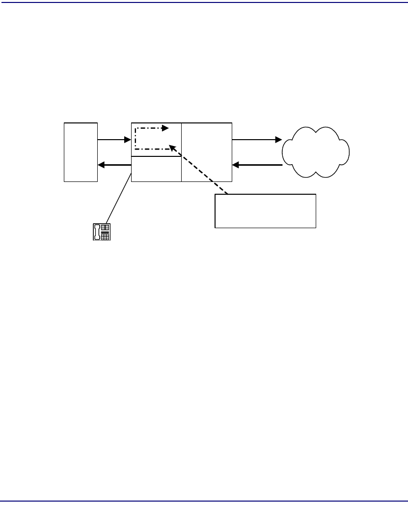
B-16 Compact T1 - Release 6.1
Diagnostices & Troubleshooting
Loopbacks Overview
V.35 Equipment Loop
Note: V.35 LED flashes yellow during equipment loop.
Loops at local V.35 port. Check for sync and errors at remote data port, with or
without BERT.
Enable Equipment Loopback
Where a V.35 card is in slot 6.
> set 6:1 equipment loopup
OK
View Status of Loopback
> show 6:1
SLOT 6:
Settings for V35 Port 1:
CTS: Always High
Timing: Source
Rx Clock Inversion: Normal
Tx Clock Inversion: Normal
Data Inversion: Normal
Data Speed: 64K
Data Rate: 1536 K
Loopback: Equipment
T1
Adit 600
Local
DCE
V.35
Loops at local V.35
port (location)
Local
DTE
FXS
Telephone
DS1
Network
Compact T1

Compact T1 - Release 6.1 B-17
Diagnostices & Troubleshooting
Loopbacks Overview
Disable Equipment Loopback
> set 6:1 equipment loopdown
OK
View Status of Loopback
> show 6:1
SLOT 6:
Settings for V35 Port 1:
CTS: Always High
Timing: Source
Rx Clock Inversion: Normal
Tx Clock Inversion: Normal
Data Inversion: Normal
Data Speed: 64K
Data Rate: 1536 K
Loopback: None

B-18 Compact T1 - Release 6.1
Diagnostices & Troubleshooting
Loopbacks Overview
V.35/V.54 Loop
V.35/V.54 Service Card Description
The V.35 Card with V.54 Loop Test provides the capability for the V.35 card to
detect network loop back initiation signals and provide a network loop back for
loop testing. Each channel of the V.35 will continuously monitor the incoming data
bit stream for a particular loop pattern. On detection of the pattern the channel will
acknowledge the loop test request and put the channel into loop back. The channel
will then continuously monitor for the loop test end pattern. On detection of the
loop end pattern the channel will remove loop back and resume normal operation.
Front panel LED’s will indicate Loop test. Each channel can also initiate the loop
test pattern causing another V.54 compatible device to loop back. The channel will
then transmit a test pattern and calculate bit error rate (BER).
View V.35/V.54 Card Configuration
Where a V.35/V.54 card is in slot 6.
> show 6:1
SLOT 6:
Settings for V35 Port 1:
CTS: Always High
Timing: Source
Rx Clock Inversion: Normal
Tx Clock Inversion: Normal
Data Inversion: Normal
Data Speed: 64K
Data Rate: 768 K
V.54 Rx LB: disabled
V.54 Rx Addr: 255
V.54 Test Addr: 255
V.54 Tx Prep count: 15
V.54 Rx Prep count: 15
V.54 Test Pattern: QRSS
V.54 Ignore ACK: OFF
Loopback: None
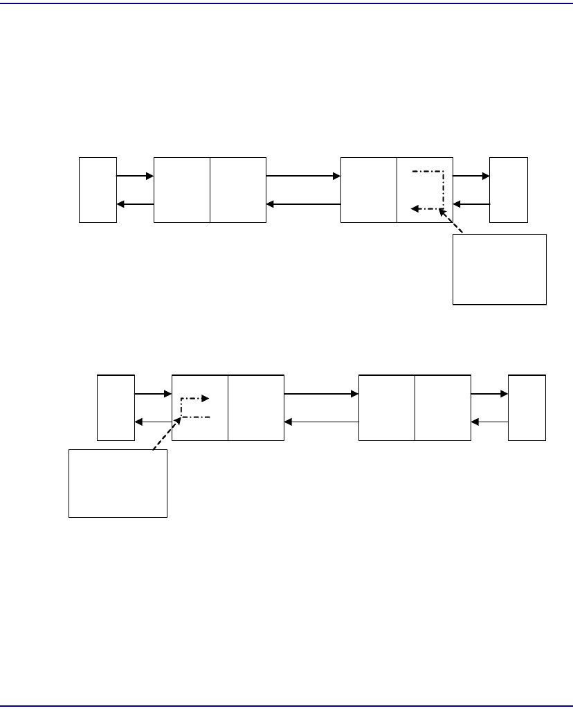
Compact T1 - Release 6.1 B-19
Diagnostices & Troubleshooting
Loopbacks Overview
V.54 Loop
Note: Local LED flashes yellow, remote LED flashes green.
Enable V.54 Loop
Where a V.35/V.54 card is in slot 6.
> set 6:1 v54 network enable
OK
Transmit V.54 Loopup
Receive V.54 Loopup
T1
Network
T1
Local
DTE
Adit 600
Equipment
Unit
Local
DCE
V.35
Adit 600
Network
Unit
Remote
DTE
Remote
DCE
V.35
Local unit send
V.54 loop up
code, loop occurs
at remote data
port
T1
Network
T1
Local
DTE
Adit 600
Equipment
Unit
Local
DCE
V.35
Adit 600
Network
Unit
Remote
DTE
Remote
DCE
V.35
Remote unit or
network sends
V.54 loop up code,
loop occurs at
local data port
Compact T1
Network
Unit
Compact T1
Equipment
Unit
Compact T1
Network
Unit
Compact T1
Equipment
Unit

B-20 Compact T1 - Release 6.1
Diagnostices & Troubleshooting
Loopbacks Overview
View Status of Loopback
> show 6:1
SLOT 6:
Settings for V35 Port 1:
CTS: Always High
Timing: Source
Rx Clock Inversion: Normal
Tx Clock Inversion: Normal
Data Inversion: Normal
Data Speed: 64K
Data Rate: 768 K
V.54 Rx LB: enabled
V.54 Rx Addr: 255
V.54 Test Addr: 255
V.54 Tx Prep count: 15
V.54 Rx Prep count: 15
V.54 Test Pattern: QRSS
V.54 Ignore ACK: OFF
Loopback: None

Compact T1 - Release 6.1 B-21
Diagnostices & Troubleshooting
Loopbacks Overview
V.54 Equipment Loopback
Enable V.54 Equipment Loopup
Where a V.35/V.54 card is in slot 6.
> set 6:1 v54 equipment loopup
OK
View Status of Loopback
> show 6:1
SLOT 6:
Settings for V35 Port 1:
CTS: Always High
Timing: Source
Rx Clock Inversion: Normal
Tx Clock Inversion: Normal
Data Inversion: Normal
Data Speed: 64K
Data Rate: 768 K
V.54 Rx LB: enabled
V.54 Rx Addr: 255
V.54 Test Addr: 255
V.54 Tx Prep count: 15
V.54 Rx Prep count: 15
V.54 Test Pattern: QRSS
V.54 Ignore ACK: OFF
Loopback: Equipment(V.54)
> status 6:1
SLOT 6:
Status for V35 PORT 1:
DCD: High
CTS: High
DSR: High
RTS: High
DTR: High
BERT: RUNNING (Syncing up)

B-22 Compact T1 - Release 6.1
Diagnostices & Troubleshooting
Loopbacks Overview
> status 6:1
SLOT 6:
Status for V35 PORT 1:
DCD: High
CTS: High
DSR: High
RTS: High
DTR: High
BERT: RUNNING
BITS: 8386950
ERRS: 0
BER: 0.00000000
Disable V.54 Equipment Loopup
> set 6:1 v54 equipment loopdown
OK
View Status of Loopback
> status 6:1
SLOT 6:
Status for V35 PORT 1:
DCD: High
CTS: High
DSR: High
RTS: High
DTR: High
BERT: Complete
BITS: 109030350
ERRS: 0
BER: 0.00000000
BERT DATE: 1/5/2001 01:39:18
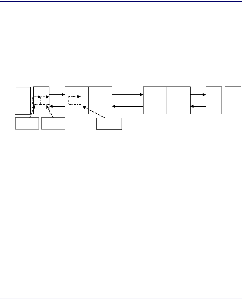
Compact T1 - Release 6.1 B-23
Diagnostices & Troubleshooting
Loopbacks Overview
OCU-DP Loopbacks
These loopbacks may be activated by the network or manually (CLI). These loopbacks
are OCU, CSU, and DSU. The Network may activate each loopback by sending
latching or non-latching code sequences. The OCU-DP card may be configured to
allow detection of each sequence for each loopback.
View OCU-DP Card Configuration
Where a OCU-DP card is in slot 3.
> show 3:1
SLOT 3:
Settings for OCUDP Port 1:
Up/Down: UP
Baudrate: 56000
Loopdetect Types Enabled:
CSU Latching
DSU Latching
OCU Latching
Error Correction: DISABLE
Secondary Channel: DISABLE
T1
Network
T1
DTE
Adit 600
Equipment
Unit
Local
DCE
Adit 600
Network
Unit
Remote
DCE
DCE
DSU/CSU
DCE
DSU/CSU DTE
DSU Loop CSU Loop OCU Loop
Compact T1
Equipment
Unit
Compact T1
Network
Unit

B-24 Compact T1 - Release 6.1
Diagnostices & Troubleshooting
Loopbacks Overview
Non-Latching Loopdetect
Enable OCU-DP Non-Latching Loopdetect
Where a OCU-DP card is in slot 3.
> set 3:1 loopdetect ocu nllb enable
OK
> set 3:1 loopdetect csu nllb enable
OK
> set 3:1 loopdetect dsu nllb enable
OK
View Status of Loopdetect
> show 3:1
SLOT 3:
Settings for OCUDP Port 1:
Up/Down: UP
Baudrate: 56000
Loopdetect Types Enabled:
CSU Latching
CSU Non-Latching
DSU Latching
DSU Non-Latching
OCU Latching
OCU Non-Latching
Error Correction: DISABLE
Secondary Channel: DISABLE
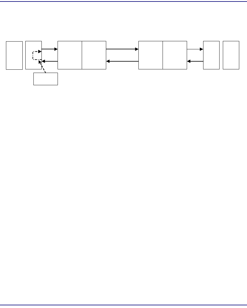
Compact T1 - Release 6.1 B-25
Diagnostices & Troubleshooting
Loopbacks Overview
CSU Manual Loopback
Enable CSU Manual Loopback
Where a OCU-DP card is in slot 3.
> set 3:1 loopback csu loopup
OK
View Status of Loopback
> status 3:1
SLOT 3:
Status for OCUDP Port 1:
Selftest:
Results as of 00:00:24 01/01/2001
Datapath: PASS
FPGA: PASS
OCU: PASS
OCU Manual Loopback: NONE
CSU Manual Loopback: In Progress
OCU NonLatching Loopback: NONE
DSU NonLatching Loopback: NONE
CSU NonLatching Loopback: NONE
OCU Latching Loopback: NONE
DSU Latching Loopback: NONE
CSU Latching Loopback: NONE
T1
Network
T1
DTE
Adit 600
Equipment
Unit
Local
DCE
Adit 600
Network
Unit
Remote
DCE
DCE
DSU/CSU
DCE
DSU/CSU DTE
CSU Loop Compact T1
Network
Unit
Compact T1
Equipment
Unit
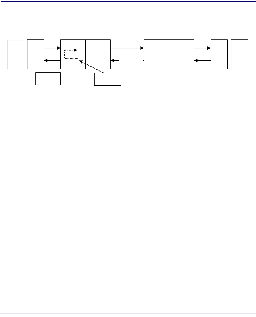
B-26 Compact T1 - Release 6.1
Diagnostices & Troubleshooting
Loopbacks Overview
Manual OCU Loopback
Enable Manual OCU Loopback
Where a OCU-DP card is in slot 3.
> set 3:1 loopback ocu loopup
OK
View Status of Loopback
> status 3:1
SLOT 3:
Status for OCUDP Port 1:
Selftest:
Results as of 00:00:24 01/01/2001
Datapath: PASS
FPGA: PASS
OCU: PASS
OCU Manual Loopback: In Progress
CSU Manual Loopback: NONE
OCU NonLatching Loopback: NONE
DSU NonLatching Loopback: NONE
CSU NonLatching Loopback: NONE
OCU Latching Loopback: NONE
DSU Latching Loopback: NONE
CSU Latching Loopback: NONE
T1
Network
T1
DTE
Adit 600
Equipment
Unit
Local
DCE
Adit 600
Network
Unit
Remote
DCE
DCE
DSU/CSU
DCE
DSU/CSU DTE
OCU Loop
Compact T1
Compact T1
Equipment
Unit
Compact T1
Network
Unit
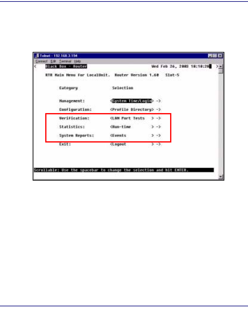
Compact T1 - Release 6.1 B-27
Diagnostices & Troubleshooting
Router Diagnostics and Performance Tools
Router Diagnostics and Performance Tools
The Verification, Statistics and System Reports features are instrumental in diagnosing
and troubleshooting the Router card.

B-28 Compact T1 - Release 6.1
Diagnostices & Troubleshooting
Router Diagnostics and Performance Tools
Verification
The Verification section may be used to identify suspected communication problems
between the local and remote devices. Verification options are:
LAN Port Tests
Verifies the ability of the local unit to commicate by pinging remote or local
devices. See LAN Port Tests in the Router Manual for more information on this
feature.
WAN Monitor
The WAN Monitor is a diagnostic tool that is used to review the actual data being
transmitted from, or received by the local Router. When the monitoring is started,
a hexadecimal display of each transmission as it occurs is shown. See WAN
Monitor in the Router Manual for more information on this feature.
Note: The WAN Monitor decreases the throughput of the Router. It should
only during installation and troubleshooting procedures, not during normal
operation.
Statistics
Run-Time
TheRun-Time is used to review data transmission information between the Local
(LAN) unit and Remote (WAN) devices. This option allows you to review data
transmission statistics to/from remote units. This data will help you to monitor the
Router’s connection/performance capabilities such as throughput, compression,
and errors. See Statistics Window in the Router Manual for more information
regarding this feature.

Compact T1 - Release 6.1 B-29
Diagnostices & Troubleshooting
Router Diagnostics and Performance Tools
System Reports
The System Reports menu presents data that may be useful in identifying WAN
communication problems.
Events
The Events listing offers on-going historical activity for the Router, while the
Alarm listing indicates events that suggest further investigation. See Events in the
Router Manual for more information regarding this feature.
Alarms
This screen provides a listing of any Alarms that have occurred on the Router.
When an Alarm is triggered, the Router LED (labeled CRD) will display a red
indicator light, which will stay on until the Alarm is cleared. Each Alarm is listed
separately and the Count field will display a value of 1. See Alarms in the Router
Manual for more information regarding this feature.
Network/Servers
By sending out IPX and IP RIP (Routing Information Protocol) and IPX SAP
(Service Advertising Protocol) packets and monitoring RIP and SAP packets from
other devices, the Router will learn about other servers and networks. The Router
will constantly monitor RIP and SAP packets to ensure that the status of the
network or server has changed. Should a RIP or SAP packet indicate a change in
status, the Router would update the data in the table and send the information to all
enabled remotes to exchange the updated data. See Networks/Servers in the Router
Manual for more information regarding this feature.
Address Tables
The MAC Address and IP Address Tables, along with Network Tables are used to
determine if and where the Router should send packets. See Address Tables in the
Router Manual for more information regarding this feature.

B-30 Compact T1 - Release 6.1
Diagnostices & Troubleshooting
Router Diagnostics and Performance Tools

GLOSSARY
AMI Automatic Mark Inversion
ARP Address Resolution Protocol
ATM Asynchronous Transfer Mode
B8ZS Bipolar with 8 Zero Substitution
BER Bit Error Rate
BERT Bit Error Rate Tester
BES Burst Errored Seconds
BIT Binary Digit
bps Bits Per Second
BPV Bipolar Violation
BRI Basic Rate Interface
CAS Channel Associated Signaling
CCS Common Channel Signaling
Glossary

Glossary-2 Compact T1 - Release 6.1
Glossary
CHAP
CHAP Challenge Handshake Authentication Protocol
CIDR Classless Inter-Domain Routing
CLASS Custom Local Area Signaling Service
CLEI Common Language Equipment Identification
CLI Command Line Interface
CMG Customer Media Gateway
CNG Also called Auto Fax Tone or Calling Tone
CO Central Office
CPE Customer Provided Equipment
CRC Cyclic Redundancy Check
CRV Call Reference Value
CSU Channel Service Unit
D4 The fourth generation channel bank
dB decibel
DCS Digital Signal Processor
DDS Digital Data Service
DHCP Dynamic Host Configuration Protocol
DLC Digital Loop Carrier
DNS Domain Naming System
DLCI Data Link Connection Identifier

Compact T1 - Release 6.1 Glossary-3
Glossary
DS0
DS0 Digital Signal Level Zero (64 kbps) (1 voice channel)
DS1 Digital Signal Level 1 (1.544 Mbps)
DSU Digital Service Unit/Data service Unit
DTE Data Terminal Equipment
ES Errored Seconds
ESF Extended Superframe
FDL Facilities Data Link
FX Foreign Exchange
FXO Foreign Exchange Office
FXS Foreign Exchange Station
GS Ground Start
GMT Greenwich Mean Time
GRE Generic Routing Encapsulation
IETF Internet Engineering Task Force
IP Internet Protocol
IPX Internet Packet eXchange
ISDN BRI Integrated Services Digital Network.
LAN Local Area Network
LLC Logical Link Control
LBO Line Build Out

Glossary-4 Compact T1 - Release 6.1
Glossary
LMI
LMI Local Management Interface
LS Loop Star
LULT Line Unit Line Termination
LUNT Line Unit Network Termination
Mbps Million Bits Per Second
MGCP Media Gateway Control Protocol
MLPPP Multilink PPP
MUX Multiplexer
MVEC Majority Vote Error Correction
NAT Network Address Translation
NCS Network-based Call Signaling
NEBS Network Equipment Building Standards
NTP Network Time Protocol
OCU-DP Office Channel Unit - Data Port
PAP Password Authentication Protocol
PHY Physical specifications
PPP Point-to-Point Protocol.
PVC Permanent Virtual Circuit
QoS Quality of Service

Compact T1 - Release 6.1 Glossary-5
Glossary
RADIUS
RADIUS Remote Authentication Dial-In Service.
RIP Routing Information Protocol.
RTCP Real-Time Control Protocol.
RTPSAP Service Access Point.
SDP Session Description Protocol.
SNMP Simple Network Management Protocol.
STP Spanning Tree Protocol.
T1 Trunk Level 1.
TACACS+ Terminal Access Controller Access Control System.
TDM Time Division Multiplex.
TFTP Trivial File Transfer Protocol.
TOS Type of Service
VC MUX Virtual Channel Multiplexer
VOIP Voice over IP.
WAN Wide Area Network.
VC Virtual Channel.
10Base-T The most widely installed Ethernet local area networks (LANs) use
ordinary telephone twisted-pair wire. When used on Ethernet, this carrier
medium is known at 10BASE-T. 10BASE-T supports Ethernet’s 10
Mbps transmission speed.

Glossary-6 Compact T1 - Release 6.1
Glossary
100Base-TX
100Base-TX Also called "Fast Ethernet," it is a 100 Mbps version of Ethernet.
100Base-T transmits at 100 Mbps rather than 10 Mbps. Like regular
Ethernet, Fast Ethernet is a shared media LAN. All nodes share the 100
Mbps bandwidth. 100Base-TX uses two pairs of Category 5 cabling, one
pair for transmission, one pair for receiving.
analog The telephone transmission of voice, video or image. Telephone
transmission and/or switching that is not digital.
Annex D A frame relay standard extension dealing with the communication and
signaling between customer premises and equipment and frame relay
network equipment for the purpose of querying network status
information.
Asynchronous
Transfer Mode Very high speed transmission technology. ATM is a high bandwidth,
low-delay, connection-oriented, packet-like switching and multiplexijng
technique. Usable capacity is segmented into 53-byte fixed-size cells,
consisting of header and information fields, allocated to services on
demand. The term "asynchronous" applies, as each cell is presented to
the network on a "start-stop" basis - in other words, asynchronously.
bandwidth The width of a communications channel. Analog is typically measured in
Hertz (cycles per second), a voice conversation is typically measured in
bits per second.
Bipolar 8-Zero
Substitution A coding scheme that maintains ones density.
bipolar violation BPV. A violation is declared for AMI if two successive pulses have the
same polarity.
Bit Contraction of the words "binary" and "digit".
Bit Error Rate The number of erred bits divided by the total number of bits.
Basic Rate
Interface Basic Rate Interface (2b+d) in ISDN.

Compact T1 - Release 6.1 Glossary-7
Glossary
Channel Service Unit
Channel Service
Unit The interface to the T1 line that terminates the local loop.
Classless Inter-
Domain Routing CIDR is a new addressing scheme for the Internet which allows for more
efficient allocation of IP addresses than the old Class A, B, and C address
scheme.
collision In Ethernet, the result of two nodes transmitting simultaneously. The
frames from each device impact and are damaged when they meet on the
physical media.
command line The command line is where you enter MS-DOS commands.
compander Companding is the process of compressing the amplitude range of a
signal for economical transmission and then expanding them back to
their original form at the receiving end.
Domain Naming
System DNS. A mechanism used in the Internet for translating names of host
computers into addresses.
Dynamic Host
Configuration
Protocol
DHCP is a network configuration that allows maintenance to be
performed from a central site rather than by end users.
encapsulation Carrying frames of one protocol as the data in another.
echo
cancellation A technique that allows for the isolation and filtering of unwanted signals
caused by echoes from the main transmitted signal.
end point A network element (component) at the end of the network, a transmitter
or receiver, or an originating or terminating device.
Facilities Data
Link FDL supports the communication of various network information in the
form of in-service monitoring and diagnostics.
filter An operating parameter used with routers that can be set to block the
transfer of packets from one LAN to another.

Glossary-8 Compact T1 - Release 6.1
Glossary
firewall
firewall Any of a number of security schemes that prevent unauthorized users
from gaining access to a computer network and/or may monitor the
transfer of information to and from the network.
frame A fragment of data that is packaged into a frame format, which comprises
a header, payload, and trailer.
Foreign
Exchange A Central Office trunk which has access to a distant central office. Dial
Tone is returned from that distant Central Office, and a location can be
reached in the area of the foreign Central Office by dialing a local
number. This will provide easier access for customers in that area and
calls may be made anywhere in the foreign exchange area for a flat rate.
Foreign
Exchange
Service
Foreign exchange (FX) service is a service that can be ordered from the
telephone company that provides local telephone service from a central
office which is outside (foreign to) the subscriber’s exchange area.
Simply, a user can pick up the phone in one city and receive a dial tone
in the foreign city. This kind of connection is provided by a type of trunk
called foreign exchange (FX) trunk. FX trunk signaling can be provided
over analog or T-1 links. Connecting POTS telephones to a computer
telephony system via T-1 links requires a channel bank configured with
FX type connections.
G.168 Echo cancellation
G.711 Pulse code modulation (PCM) of voice frequencies. This ITU-T
Recommendation provides the rules for encoding of voice-frequency
signals to and from 64 kbps PCM. It covers both "A-law" and "µ-law"
encoding.
G.726 40, 32, 24, 16 kbps adaptive differential pulse code modulation
(ADPCM). This ITU-T Recommendation specifies the conversions of a
64 kbps A-law and u-law PCM channel to and from ADPCM encodings
of 40, 32, 24, and 16 kbps. (The PCM encoding is defined in G.711.)
gateway An entrance and exit into a communications network
GRE tunneling Generic Routing Encapsulation tunneling is a Layer 2 protocol that can
tunnel multi-protocol traffic over IP Networks.

Compact T1 - Release 6.1 Glossary-9
Glossary
ground
ground A physical connection to the earth or other reference point.
ground start A method of signaling on subscriber trunks in which one side of the two
wire trunk (typically the ring conductor of Tip and Ring) is momentarily
grounded to get dial tone
Hops Each individual short trip that packets make from router to router, as they
are routed to their destination.
impedance The total opposition a circuit offers to the flow of alternating current. It
is measured in ohms and the lower the ohmic value, the better the quality
of the conductor
Integrated
Services Digital
Network
BRI, which is 144,000 bits per second and designed for the desktop.
Local Area
Network LAN. A short distance data communications network (typically within a
building or campus) used to link together computers and peripheral
devices under some form of standard control.
layer 2 In the OSI 7 layer model, layer 2 is the Data Link layer. This layer deals
with procedures and protocols from operating the communications lines.
It also has a way of detecting and correcting message errors
Line Build Out LBO.
Local Link
Control A protocol developed by the IEEE 802.2 committee for data-link-level
transmission control
Local
Management
Interface
A specification for the use of frame-relay products that define a method
of exchanging status information between devices such as routers
latching OCU-DP loopback
loopback A diagnostic test in which a signal is transmitted across a medium while
the sending device waits for its return.

Glossary-10 Compact T1 - Release 6.1
Glossary
MAC Address
MAC Address The address for a device as it is identified at the Media Access Control
layer in the network architecture
mapping In network operations, the logical association of one set of values, such
as addresses on one network, with quantities or values of another set,
such as devices on another network.
Media Gateway
Control Protocol MGCP. A control and signal standard for the conversion of audio signals
carried on telephone circuits (PSTN) to data packets carried over the
Internet or other packet networks.
MLPPP MultiLink PPP. An extension to the point-to-point protocol that enables
two channels to be linked together to double the throughput. It is used for
ISDN transmission and channel bonding
multiplexer Electronic equipment which allows two or more signals to pass over one
communications circuit. The circuit may be analog or digital
MUX See multiplexer
MVEC Majority Vote Error Correction
nonlatching OCU-DP loopback
NTP Network Time Protocol, developed to maintain a common sense of time
among Internet hosts around the world. Many systems on the Internet run
NTP, and have the same time (relative to Greenwich Mean Time).
OCU-DP Office Channel Unit - Data Port. A channel bank unit used to interface
between the channel bank and a customer’s DDS CSU or DSU.
packet A packet consists of the data to be transmitted and certain control
information.
PAP Password Authentication Protocol
PAT Port Address Translation

Compact T1 - Release 6.1 Glossary-11
Glossary
PHY
PHY PHY as in physical specifications. OSI Physical Layer, which provides
for transmission of cells over a physical medium connecting two ATM
devices.
ping Packet InterNet Grouper. PING is a program used to test whether a
particular network destination on the Internet is online (i.e. working) by
repeatedly bouncing a "signal" off a specified address and seeing how
long that signal takes to complete the round trip. No return signal - site is
down or unreachable. Portion is returned - trouble with the connection.
PLAR Private Line, Automatic Ringdown. A leased voice circuit that connects
two single instruments together. When either handset is lifted, the other
instrument automatically rings.
PPP Point-to-Point Protocol.
protocol Procedure or set of rules.
PVC Permanent Virtual Circuit. A PVC is a permanent channel connection
between two ATM devices. PVC’s allow network transmissions to be
started without having to first establish a connection with the end point
ATM device. When a PVC is constructed, the end points of the
connection will agree upon a path in which data will travel, and therefore
agree upon the route that data will travel to reach its destination.
QoS Quality of Service.
RADIUS Remote Authentication Dial-In Service. RADIUS is a client/server-
based authentication software system. The software supports remote
access applications, allowing an organization to maintain user profiles in
a centralized database residing on an authentication server which can be
shared by multiple remote access servers.

Glossary-12 Compact T1 - Release 6.1
Glossary
RIP
RIP Routing Information Protocol. RIP is based on distance vector
algorithms that measure the shortest path between two points on a
network, based on the addresses of the originating and destination
devices. The shortest path is determined by the number of "hops"
between those points. Each router maintains a routing table, or routing
database, of known addresses and routes; each router periodically
broadcasts the contents of its table to neighboring routers in order that the
entire network can maintain a synchronized database.
robbed bit A type of analog signaling that will occasionally steal information bits
used for circuit signaling coding.
RTCP Real-Time Control Protocol.
SAP Service Access Point.
silence
suppression A term used in voice compression for transmission whereby silence in
the voice conversation is filled with other transmissions (data, video,
imaging, etc.).
SNMP Simple Network Management Protocol. SNMP is the most common
method by which network managements applications can query a
management agent using a supported MIB (Management Information
Base). SNMP operates at the OSI application layer.
spanning tree Spanning Tree Protocol is a link management protocol that provides path
redundancy while preventing undesirable loops in the network. For an
Ethernet network to function properly, only one active path can exist
between two stations.
SDP Session Description Protocol.
T1 Trunk Level 1. A digital transmission link with a total signaling speed of
1.544 Mbps. T-1 is a standard for the digital transmission in North
America.
TACACS+ Terminal Access Controller Access Control System.

Compact T1 - Release 6.1 Glossary-13
Glossary
telnet
telnet An Internet standard protocol that enables a computer to function as a
terminal working from a remote computer
TDM Time Division Multiplex. A technique for transmitting a number of
separate data, voice and/or video signals simultaneously over one
communications medium by quickly interleaving a piece of each signal
one after another.
TFTP Trivial File Transfer Protocol.
ticks The distance between two networks, measured in time increments. Ticks
may be used to designate primary and secondary routes to the same
network.
trunk A communication line between two switching systems.
tunneling To provide a secure, temporary path over the Internet.
VC MUX Virtual Channel Multiplexer
VoIP Voice over IP.
WAN Wide Area Network.
VC Virtual Channel.

Glossary-14 Compact T1 - Release 6.1
Glossary
VC

INDEX
Numerics
10Base-T . . . . . . . . . . . . . . . . . .3-4, Glossary-5
115 VAC/-48 VDC Power Supply/Charger .11-2
25-pair telco connector pinout . . . . . . . . . . . .3-9
26-pin micro-SCSI
V.35 card . . . . . . . . . . . . . . . . . . . . . . . . . 15-9
V.35/V.54 cards . . . . . . . . . . . . . . . 15-8, 15-9
3-DSO BRITE mode . . . . . . . . . . . . . . . . . . .9-2
A
aco (alarm Cut Off) command . . . . . . . . . . . .5-5
add
(router)
dns proxy command . . . . . . . . . . . . . . .5-7
remote command . . . . . . . . . . . . . . . . . .5-7
snmp community command . . . . . . . . .5-8
snmp trap command . . . . . . . . . . . . . . .5-9
static dns host command . . . . . . . . . . .5-10
uploaduser command . . . . . . . . . . . . . . 5-11
(router-lan)
filter
address command . . . . . . . . . . . . . .5-12
custom command . . . . . . . . . . . . . . 5-13
protocol command . . . . . . . . . . . . . .5-14
secondary ip address command . . . . . .5-15
static
ip address command . . . . . . . . . . . .5-16
ip network command . . . . . . . . . . . .5-17
ipx network command . . . . . . . . . . .5-18
mac address command . . . . . . . . . .5-19
(router-wan)
firewall command . . . . . . . . . . . . . . . . 5-20
gre network command . . . . . . . . . . . . . 5-23
nat bypass command . . . . . . . . . . . . . . 5-24
static
ip address command . . . . . . . . . . . . 5-25
ip network command . . . . . . . . . . . 5-26
ipx network command . . . . . . . . . . 5-27
mac address command . . . . . . . . . . 5-28
nat address command . . . . . . . . . . . 5-29
command . . . . . . . . . . . . . . . . . . . . . . . . . . 5-6
user command . . . . . . . . . . . . . . . . . . . . . 5-29
alarm connector . . . . . . . . . . . . . . . . . . . . . . . 3-8
alarms command . . . . . . . . . . . . . . . . . . . . . 5-30
alert alarm . . . . . . . . . . . . . . . . . . . . . 5-30, 5-61
algorithm . . . . . . . . . . . . . . . . . . . . . . . . . . 5-169
altitude . . . . . . . . . . . . . . . . . . . . . . . . . . . . . . 2-2
Analog . . . . . . . . . . . . . . . . . . . . . . . . Glossary-6
Annex D . . . . . . . . . . . . . . . . . . . . . . . Glossary-6
Assembly of unit . . . . . . . . . . . . . . . . . . . . . . 2-3
autologout . . . . . . . . . . . . . . . . . . . . . . . . . . 5-93
B
B8ZS . . . . . . . . . . . . . . . . . . . . . . . . . Glossary-1
Basic Setup . . . . . . . . . . . . . . . . . . . . . . . . . . 4-7
Basics, SNMP . . . . . . . . . . . . . . . . . . . . . . . .A-2
baud rate . . . . . . . . . . . . . . . . . . . . . . . . . . . 5-86
BERT . . . . . . . . . . . . . . . . . . . . . . . . . Glossary-1
Bipolar 8 Zero Substitution . . . . . . . . Glossary-1
Bit . . . . . . . . . . . . . . . . . . . . . . . . . . . Glossary-6
bps . . . . . . . . . . . . . . . . . . . . . . . . . . . Glossary-1
BRI . . . . . . . . . . . . . . . . . . . . . . . . . . . Glossary-1
Index

Index - 2 Compact T1 - Release 6.1
Index
C
C
cabling . . . . . . . . . . . . . . . . . . . . . . . . . . 3-2, 3-3
Call Detail Recording . . . . . . . . . . . . . . . . . 5-94
Channel Associated Signaling . . . . . . . . . . . 5-37
FXO . . . . . . . . . . . . . . . . . . . . . . . . . . . . . . 7-9
FXS . . . . . . . . . . . . . . . . . . . . . . . . . . . . . 8-10
CHAP . . . . . . . . . . . . . . . . . . . . . . . . Glossary-2
Chassis . . . . . . . . . . . . . . . . . . . . . . . . . . . . . 1-10
chassis dimensions . . . . . . . . . . . . . . . . . . . . 1-9
Chassis Ground Connector . . . . . . . . . . . . . . 3-5
CIDR . . . . . . . . . . . . . . . . . . . . . . . . . Glossary-2
clear
(router)
ip address table command . . . . . . . . . . 5-33
log command . . . . . . . . . . . . . . . . . . . 5-33
mac address table command . . . . . . . . 5-34
mgcp stats command . . . . . . . . . . . . . 5-34
performance command . . . . . . . . . . . . 5-35
command . . . . . . . . . . . . . . . . . . . . . . . . . 5-31
ds1 command . . . . . . . . . . . . . . . . . . . . . 5-32
log command . . . . . . . . . . . . . . . . . . . . . . 5-32
CLI (Command Line Interface) . 1-7, Glossary-2
CLI commands
aco (Alarm Cut Off) . . . . . . . . . . . . . . . . . 5-5
add . . . . . . . . . . . . . . . . . . . . . . . . . . . . . . . 5-6
(router)
dns proxy . . . . . . . . . . . . . . . . . . . . . 5-7
remote . . . . . . . . . . . . . . . . . . . . . . . . 5-7
snmp community . . . . . . . . . . . . . . . 5-8
snmp trap . . . . . . . . . . . . . . . . . . . . . 5-9
static dns host . . . . . . . . . . . . . . . . . 5-10
uploaduser . . . . . . . . . . . . . . . . . . . 5-11
(router-lan)
filter address . . . . . . . . . . . . . . . . . . 5-12
filter custom . . . . . . . . . . . . . . . . . . 5-13
filter protocol . . . . . . . . . . . . . . . . . 5-14
secondary ip address . . . . . . . . . . . . 5-15
static ip address . . . . . . . . . . . . . . . 5-16
static ip network . . . . . . . . . . . . . . . 5-17
static ipx network . . . . . . . . . . . . . . 5-18
static mac address . . . . . . . . . . . . . 5-19
(router-wan)
firewall . . . . . . . . . . . . . . . . . . . . . . 5-20
gre network . . . . . . . . . . . . . . . . . . 5-23
nat bypass . . . . . . . . . . . . . . . . . . . . 5-24
static ip address . . . . . . . . . . . . . . . 5-25
static ip network . . . . . . . . . . . . . . . 5-26
static ipx network . . . . . . . . . . . . . . 5-27
static mac address . . . . . . . . . . . . . 5-28
static nat address . . . . . . . . . . . . . . 5-29
user . . . . . . . . . . . . . . . . . . . . . . . . . . . 5-29
alarms . . . . . . . . . . . . . . . . . . . . . . . . . . . 5-30
clear . . . . . . . . . . . . . . . . . . . . . . . . . . . . 5-31
(router)
ip address table . . . . . . . . . . . . . . . . 5-33
log . . . . . . . . . . . . . . . . . . . . . . . . . 5-33
mac address table . . . . . . . . . . . . . . 5-34
mgcp stats . . . . . . . . . . . . . . . . . . . 5-34
performance . . . . . . . . . . . . . . . . . . 5-35
ds1 . . . . . . . . . . . . . . . . . . . . . . . . . . . 5-32
log . . . . . . . . . . . . . . . . . . . . . . . . . . . . 5-32
connect . . . . . . . . . . . . . . . . . . . . . . . . . . 5-36
(bri) . . . . . . . . . . . . . . . . . . . . . . . . . . . 5-36
(card-trunk) (card-trunk) . . . . . . . . . . 5-39
(router-trunk) (t1) . . . . . . . . . . . . . . . . 5-38
(router-voice) (t1|fxs) . . . . . . . . . . . . . 5-40
delete . . . . . . . . . . . . . . . . . . . . . . . . . . . . 5-41
(router)
dns proxy . . . . . . . . . . . . . . . . . . . . 5-42
remote . . . . . . . . . . . . . . . . . . . . . . 5-42
snmp community . . . . . . . . . . . . . . 5-43
snmp trap . . . . . . . . . . . . . . . . . . . . 5-43
static dns host . . . . . . . . . . . . . . . . . 5-44
uploaduser . . . . . . . . . . . . . . . . . . . 5-44
(router-lan)
filter . . . . . . . . . . . . . . . . . . . . . . . . 5-45
secondary ip address . . . . . . . . . . . 5-46

Compact T1 - Release 6.1 Index - 3
Index
C
static ip address . . . . . . . . . . . . . . . .5-47
static ip network . . . . . . . . . . . . . . .5-48
static ipx network . . . . . . . . . . . . . .5-49
static mac address . . . . . . . . . . . . . .5-50
(router-wan)
firewall . . . . . . . . . . . . . . . . . . . . . .5-50
gre network . . . . . . . . . . . . . . . . . . .5-51
nat bypass . . . . . . . . . . . . . . . . . . . .5-52
static ip address . . . . . . . . . . . . . . . .5-53
static ip network . . . . . . . . . . . . . . .5-54
static ipx network . . . . . . . . . . . . . .5-54
static mac address . . . . . . . . . . . . . .5-55
static nat address . . . . . . . . . . . . . . .5-56
user . . . . . . . . . . . . . . . . . . . . . . . . . . .5-56
disconnect . . . . . . . . . . . . . . . . . . . . . . . .5-57
exit . . . . . . . . . . . . . . . . . . . . . . . . . . . . . .5-57
install (slot) router . . . . . . . . . . . . . . . . . .5-58
load
tftp . . . . . . . . . . . . . . . . . . . . . . . . . . . .5-59
xmodem . . . . . . . . . . . . . . . . . . . . . . . .5-60
log . . . . . . . . . . . . . . . . . . . . . . . . . . . . . .5-61
ping . . . . . . . . . . . . . . . . . . . . . . . . . . . . .5-62
print
config . . . . . . . . . . . . . . . . . . . . . . . . . .5-63
help . . . . . . . . . . . . . . . . . . . . . . . . . . . 5-64
rename (router) . . . . . . . . . . . . . . . . . . . .5-64
reset . . . . . . . . . . . . . . . . . . . . . . . . . . . . .5-65
(router) . . . . . . . . . . . . . . . . . . . . . . . . .5-65
restore defaults . . . . . . . . . . . . . . . . . . . . . 5-66
rtrping . . . . . . . . . . . . . . . . . . . . . . . . . . .5-67
set . . . . . . . . . . . . . . . . . . . . . . . . . . . . . . .5-68
(bri) . . . . . . . . . . . . . . . . . . . . . . . . . . .5-71
autoactivate . . . . . . . . . . . . . . . . . . . 5-72
mode . . . . . . . . . . . . . . . . . . . . . . . .5-72
pmsync . . . . . . . . . . . . . . . . . . . . . .5-73
(ds0) . . . . . . . . . . . . . . . . . . . . . . . . . . . 5-75
(ds1) . . . . . . . . . . . . . . . . . . . . . . . . . . . 5-76
(fxo) . . . . . . . . . . . . . . . . . . . . . . . . . . .5-79
(fxs5G) . . . . . . . . . . . . . . . . . . . . . . . . .5-80
(ocudp)
baud . . . . . . . . . . . . . . . . . . . . . . . . 5-86
loopback . . . . . . . . . . . . . . . . . . . . . 5-87
loopdetect . . . . . . . . . . . . . . . . . . . . 5-88
mvec . . . . . . . . . . . . . . . . . . . . . . . . 5-89
secondary . . . . . . . . . . . . . . . . . . . . 5-89
selftest . . . . . . . . . . . . . . . . . . . . . . . 5-90
up/down . . . . . . . . . . . . . . . . . . . . . 5-90
(router)
autologout . . . . . . . . . . . . . . . . . . . . 5-93
default . . . . . . . . . . . . . . . . . . . . . . . 5-95
dhcp . . . . . . . . . . . . . . . . . . . . . . . . 5-96
disable . . . . . . . . . . . . . . . . . . . . . 5-96
relay server . . . . . . . . . . . . . . . . . 5-96
server dnsserver . . . . . . . . . . . . . 5-97
server domain . . . . . . . . . . . . . . . 5-97
server duration . . . . . . . . . . . . . . 5-98
server netbios nameserver . . . . . 5-98
server netbios nodetype . . . . . . . 5-99
server netbios scope . . . . . . . . . . 5-99
server startaddr . . . . . . . . . . . . . 5-100
dns . . . . . . . . . . . . . . . . . . . . . . . . . 5-101
domain . . . . . . . . . . . . . . . . . . . 5-101
name . . . . . . . . . . . . . . . . . . . . . 5-101
resolver . . . . . . . . . . . . . . . . . . . 5-102
server . . . . . . . . . . . . . . . . . . . . 5-102
enhanced security . . . . . . . . . . . . . 5-103
hookflash . . . . . . . . . . . . . . . . . . . 5-103
lmi . . . . . . . . . . . . . . . . . . . . . . . . . 5-104
poll . . . . . . . . . . . . . . . . . . . . . . 5-104
log . . . . . . . . . . . . . . . . . . . . . . . . . 5-105
login auth . . . . . . . . . . . . . . . . . . . 5-106
login prompt . . . . . . . . . . . . . . . . . 5-107
mgcp . . . . . . . . . . . . . . . . . . . . . . . 5-108
addressformat . . . . . . . . . . . . . . 5-108
algorithmname . . . . . . . . . . . . . 5-109
callagent address . . . . . . . . . . . . 5-110
callagent filter . . . . . . . . . . . . . . 5-110
callagent port . . . . . . . . . . . . . . 5-111

Index - 4 Compact T1 - Release 6.1
Index
C
callagent secondary address . . . 5-112
callagent secondary port . . . . . . 5-113
default . . . . . . . . . . . . . . . . . . . 5-113
dialstring format . . . . . . . . . . . . 5-114
down . . . . . . . . . . . . . . . . . . . . . 5-115
gatewayid . . . . . . . . . . . . . . . . . 5-116
keepalive . . . . . . . . . . . . . . . . . 5-117
package default . . . . . . . . . . . . 5-118
parsemode . . . . . . . . . . . . . . . . 5-119
piggyback . . . . . . . . . . . . . . . . . 5-120
port . . . . . . . . . . . . . . . . . . . . . . 5-120
protocolidt . . . . . . . . . . . . . . . . 5-121
quarantine . . . . . . . . . . . . . . . . . 5-122
report hookswitch . . . . . . . . . . . 5-122
retries . . . . . . . . . . . . . . . . . . . . 5-123
rsipwildcard . . . . . . . . . . . . . . . 5-123
sdpmode . . . . . . . . . . . . . . . . . . 5-124
timeout . . . . . . . . . . . . . . . . . . . 5-124
tos . . . . . . . . . . . . . . . . . . . . . . . 5-125
up . . . . . . . . . . . . . . . . . . . . . . . 5-126
version . . . . . . . . . . . . . . . . . . . 5-126
ntp . . . . . . . . . . . . . . . . . . . . . . . . . 5-127
enable/disable . . . . . . . . . . . . . . 5-127
poll . . . . . . . . . . . . . . . . . . . . . . 5-127
server . . . . . . . . . . . . . . . . . . . . 5-128
timezone . . . . . . . . . . . . . . . . . . 5-128
password . . . . . . . . . . . . . . . . . . . . 5-129
ppp auth . . . . . . . . . . . . . . . . . . . . 5-130
byremote protocol . . . . . . . . . . 5-130
byremote secret . . . . . . . . . . . . 5-130
byremote user . . . . . . . . . . . . . . 5-131
ofremote protocol . . . . . . . . . . . 5-131
ppp security . . . . . . . . . . . . . . . . . 5-132
address . . . . . . . . . . . . . . . . . . . 5-132
password . . . . . . . . . . . . . . . . . 5-132
server . . . . . . . . . . . . . . . . . . . . 5-133
priority tos . . . . . . . . . . . . . . . . . . 5-134
proxy . . . . . . . . . . . . . . . . . . . . . . . 5-135
reboot . . . . . . . . . . . . . . . . . . . . . . 5-136
rip . . . . . . . . . . . . . . . . . . . . . . . . . 5-136
snmp . . . . . . . . . . . . . . . . . . . . . . . 5-137
contact . . . . . . . . . . . . . . . . . . . 5-137
location . . . . . . . . . . . . . . . . . . 5-137
name . . . . . . . . . . . . . . . . . . . . 5-138
stp . . . . . . . . . . . . . . . . . . . . . . . . . 5-139
bridge forwarddelay . . . . . . . . . 5-139
bridge hellotime . . . . . . . . . . . . 5-139
bridge maxage . . . . . . . . . . . . . 5-140
bridge priority . . . . . . . . . . . . . 5-140
enable/disable . . . . . . . . . . . . . 5-141
syslog . . . . . . . . . . . . . . . . . . . . . . 5-142
enable/disable . . . . . . . . . . . . . 5-142
facility . . . . . . . . . . . . . . . . . . . 5-142
level . . . . . . . . . . . . . . . . . . . . . 5-143
server . . . . . . . . . . . . . . . . . . . . 5-143
voip . . . . . . . . . . . . . . . . . . . . . . . 5-144
default . . . . . . . . . . . . . . . . . . . 5-144
dtmf edge . . . . . . . . . . . . . . . . . 5-144
g729a . . . . . . . . . . . . . . . . . . . . 5-145
jitterbuffer . . . . . . . . . . . . . . . . 5-146
osi . . . . . . . . . . . . . . . . . . . . . . 5-146
packing . . . . . . . . . . . . . . . . . . 5-147
payload type . . . . . . . . . . . . . . . 5-147
ptime . . . . . . . . . . . . . . . . . . . . 5-148
rtcp
cname . . . . . . . . . . . . . . . . . 5-149
interval . . . . . . . . . . . . . . . . . 5-149
rtp baseport . . . . . . . . . . . . . . . 5-150
rtpmap . . . . . . . . . . . . . . . . . . . 5-151
sdpaddress . . . . . . . . . . . . . . . . 5-152
(router-lan)
collision . . . . . . . . . . . . . . . . . . . . 5-153
interval . . . . . . . . . . . . . . . . . . . 5-153
threshold . . . . . . . . . . . . . . . . . 5-154
filter forward . . . . . . . . . . . . . . . . 5-155
framing . . . . . . . . . . . . . . . . . . . . . 5-156
gateway . . . . . . . . . . . . . . . . . . . . 5-157
ip address . . . . . . . . . . . . . . . . . . . 5-158

Compact T1 - Release 6.1 Index - 5
Index
C
ipx network . . . . . . . . . . . . . . . . . .5-159
phy . . . . . . . . . . . . . . . . . . . . . . . . .5-160
rip . . . . . . . . . . . . . . . . . . . . . . . . .5-161
ip . . . . . . . . . . . . . . . . . . . . . . . . 5-161
ipx . . . . . . . . . . . . . . . . . . . . . . . 5-162
stp . . . . . . . . . . . . . . . . . . . . . . . . .5-163
enable/disable . . . . . . . . . . . . . .5-163
port cost . . . . . . . . . . . . . . . . . . .5-164
port priority . . . . . . . . . . . . . . . .5-164
up/down . . . . . . . . . . . . . . . . . . . . .5-165
(router-trunk)
encapsulation . . . . . . . . . . . . . . . . .5-166
multilink group . . . . . . . . . . . . . . .5-166
up/down . . . . . . . . . . . . . . . . . . . . .5-167
(router-voice)
algorithm preference . . . . . . . . . . .5-169
cpd . . . . . . . . . . . . . . . . . . . . . . . . .5-170
default . . . . . . . . . . . . . . . . . . . . . .5-171
down . . . . . . . . . . . . . . . . . . . . . . .5-172
dtmfrelay . . . . . . . . . . . . . . . . . . . .5-173
echo cancellation . . . . . . . . . . . . . .5-173
echo tail . . . . . . . . . . . . . . . . . . . . .5-174
endpoint prefix . . . . . . . . . . . . . . .5-175
endpoint suffix . . . . . . . . . . . . . . .5-176
log start . . . . . . . . . . . . . . . . . . . . .5-177
log stop . . . . . . . . . . . . . . . . . . . . .5-177
rxgain . . . . . . . . . . . . . . . . . . . . . . .5-178
silence . . . . . . . . . . . . . . . . . . . . . .5-179
slash . . . . . . . . . . . . . . . . . . . . . . . .5-180
tos . . . . . . . . . . . . . . . . . . . . . . . . .5-180
txgain . . . . . . . . . . . . . . . . . . . . . . .5-181
up . . . . . . . . . . . . . . . . . . . . . . . . . .5-181
voice bandwidth limit . . . . . . . . . .5-168
(router-wan)
cdr . . . . . . . . . . . . . . . . . . . . . . . . . .5-94
compander . . . . . . . . . . . . . . . . . . . .5-94
dlci . . . . . . . . . . . . . . . . . . . . . . . . .5-182
ip . . . . . . . . . . . . . . . . . . . . . . . . . .5-185
ip address . . . . . . . . . . . . . . . . . . . .5-185
ipx . . . . . . . . . . . . . . . . . . . . . . . . . 5-186
nat . . . . . . . . . . . . . . . . . . . . . . . . . 5-187
address . . . . . . . . . . . . . . . . . . . 5-187
enable/disable . . . . . . . . . . . . . . 5-188
ports . . . . . . . . . . . . . . . . . . . . . 5-188
other . . . . . . . . . . . . . . . . . . . . . . . 5-189
ppp . . . . . . . . . . . . . . . . . . . . . . . . 5-190
auth ofremote user . . . . . . . . . . 5-190
compression . . . . . . . . . . . . . . . 5-191
security server . . . . . . . . . . . . . . 5-191
rip . . . . . . . . . . . . . . . . . . . . . . . . . 5-192
ip updates . . . . . . . . . . . . . . . . . 5-192
ipx updates . . . . . . . . . . . . . . . . 5-192
stp . . . . . . . . . . . . . . . . . . . . . . . . . 5-193
enable/disable . . . . . . . . . . . . . . 5-193
port cost . . . . . . . . . . . . . . . . . . 5-194
port priority . . . . . . . . . . . . . . . . 5-194
trunk . . . . . . . . . . . . . . . . . . . . . . . 5-195
up/down . . . . . . . . . . . . . . . . . . . . 5-195
(v35) . . . . . . . . . . . . . . . . . . . . . . . . . 5-202
(v54) . . . . . . . . . . . . . . . . . . . . . . . . . 5-204
alarms . . . . . . . . . . . . . . . . . . . . . . . . . 5-70
autoexit . . . . . . . . . . . . . . . . . . . . . . . . 5-70
clock . . . . . . . . . . . . . . . . . . . . . . . . . . 5-74
date . . . . . . . . . . . . . . . . . . . . . . . . . . . 5-74
ethernet ip address . . . . . . . . . . . . . . . . 5-79
id . . . . . . . . . . . . . . . . . . . . . . . . . . . . . 5-81
ip gateway . . . . . . . . . . . . . . . . . . . . . . 5-81
ipds0 . . . . . . . . . . . . . . . . . . . . . . . . . . 5-82
local . . . . . . . . . . . . . . . . . . . . . . . . . . . 5-83
login auth . . . . . . . . . . . . . . . . . . . . . . 5-83
login support . . . . . . . . . . . . . . . . . . . . 5-83
ntp . . . . . . . . . . . . . . . . . . . . . . . . . . . . 5-84
disable . . . . . . . . . . . . . . . . . . . . . . . 5-84
enable . . . . . . . . . . . . . . . . . . . . . . . 5-84
poll . . . . . . . . . . . . . . . . . . . . . . . . . 5-84
server address . . . . . . . . . . . . . . . . . 5-85
timezone . . . . . . . . . . . . . . . . . . . . . 5-85
radius identifier . . . . . . . . . . . . . . . . . . 5-91

Index - 6 Compact T1 - Release 6.1
Index
C
radius retries . . . . . . . . . . . . . . . . . . . . 5-91
radius server address . . . . . . . . . . . . . . 5-92
radius server secret . . . . . . . . . . . . . . . 5-92
radius timeout . . . . . . . . . . . . . . . . . . . 5-93
screen . . . . . . . . . . . . . . . . . . . . . . . . 5-196
snmp . . . . . . . . . . . . . . . . . . . . . . . . . 5-197
syslog . . . . . . . . . . . . . . . . . . . . . . . . 5-198
disable . . . . . . . . . . . . . . . . . . . . . . 5-198
enable . . . . . . . . . . . . . . . . . . . . . . 5-198
server address . . . . . . . . . . . . . . . . 5-199
server facility . . . . . . . . . . . . . . . . 5-198
server level . . . . . . . . . . . . . . . . . . 5-199
time . . . . . . . . . . . . . . . . . . . . . . . . . . 5-200
user
level . . . . . . . . . . . . . . . . . . . . . . . 5-201
password . . . . . . . . . . . . . . . . . . . . 5-201
verification . . . . . . . . . . . . . . . . . . . . 5-206
show . . . . . . . . . . . . . . . . . . . . . . . . . . . 5-207
(bri) . . . . . . . . . . . . . . . . . . . . . . . . . . 5-208
(ds0) . . . . . . . . . . . . . . . . . . . . . . . . . 5-210
(ds1) . . . . . . . . . . . . . . . . . . . . . . . . . 5-211
(fxo) . . . . . . . . . . . . . . . . . . . . . . . . . 5-212
(fxs5G) . . . . . . . . . . . . . . . . . . . . . . . 5-213
(ocudp) . . . . . . . . . . . . . . . . . . . . . . . 5-217
(router) . . . . . . . . . . . . . . . . . . . . . . . 5-218
dhcp . . . . . . . . . . . . . . . . . . . . . . . 5-220
dns . . . . . . . . . . . . . . . . . . . . . . . . 5-220
dns proxy . . . . . . . . . . . . . . . . . . . 5-221
lmi . . . . . . . . . . . . . . . . . . . . . . . . . 5-221
log . . . . . . . . . . . . . . . . . . . . . . . . . 5-222
mgcp . . . . . . . . . . . . . . . . . . . . . . . 5-223
algorithmname . . . . . . . . . . . . . 5-224
ntp . . . . . . . . . . . . . . . . . . . . . . . . . 5-225
ppp . . . . . . . . . . . . . . . . . . . . . . . . 5-226
rip . . . . . . . . . . . . . . . . . . . . . . . . . 5-227
snmp . . . . . . . . . . . . . . . . . . . . . . . 5-227
stp . . . . . . . . . . . . . . . . . . . . . . . . . 5-228
syslog . . . . . . . . . . . . . . . . . . . . . . 5-228
uploaduser . . . . . . . . . . . . . . . . . . 5-229
voip . . . . . . . . . . . . . . . . . . . . . . . 5-230
(router-lan) . . . . . . . . . . . . . . . . . . . . 5-231
collision . . . . . . . . . . . . . . . . . . . . 5-233
filter . . . . . . . . . . . . . . . . . . . . . . . 5-234
static . . . . . . . . . . . . . . . . . . . . . . . 5-236
ip address . . . . . . . . . . . . . . . . . 5-236
ip network . . . . . . . . . . . . . . . . 5-237
ipx network . . . . . . . . . . . . . . . 5-237
mac address . . . . . . . . . . . . . . . 5-238
stp . . . . . . . . . . . . . . . . . . . . . . . . . 5-238
(router-voice) . . . . . . . . . . . . . . . . . . 5-239
(router-wan) . . . . . . . . . . . . . . . . . . . 5-240
firewall . . . . . . . . . . . . . . . . . . . . . 5-242
nat bypass . . . . . . . . . . . . . . . . . . . 5-242
ppp . . . . . . . . . . . . . . . . . . . . . . . . 5-243
static ip address . . . . . . . . . . . . . . 5-244
static ip network . . . . . . . . . . . . . . 5-244
static ipx network . . . . . . . . . . . . . 5-245
static mac address . . . . . . .5-245, 5-246
stp . . . . . . . . . . . . . . . . . . . . . . . . . 5-246
trunk . . . . . . . . . . . . . . . . . . . . . . . 5-247
(v35) . . . . . . . . . . . . . . . . . . . . . . . . . 5-250
(v54) . . . . . . . . . . . . . . . . . . . . . . . . . 5-251
(wan) . . . . . . . . . . . . . . . . . . . . . . . . 5-252
autoexit . . . . . . . . . . . . . . . . . . . . . . . 5-208
clock . . . . . . . . . . . . . . . . . . . . . . . . . 5-209
connect . . . . . . . . . . . . . . . . . . . . . . . 5-209
date . . . . . . . . . . . . . . . . . . . . . . . . . . 5-210
ethernet . . . . . . . . . . . . . . . . . . . . . . . 5-212
id . . . . . . . . . . . . . . . . . . . . . . . . . . . . 5-215
impedance . . . . . . . . . . . . . . . . . . . . 5-214
ip . . . . . . . . . . . . . . . . . . . . . . . . . . . . 5-215
ipds0 . . . . . . . . . . . . . . . . . . . . . . . . . 5-215
local . . . . . . . . . . . . . . . . . . . . . . . . . 5-216
login . . . . . . . . . . . . . . . . . . . . . . . . . 5-216
ntp . . . . . . . . . . . . . . . . . . . . . . . . . . . 5-216
radius . . . . . . . . . . . . . . . . . . . . . . . . 5-217
screen . . . . . . . . . . . . . . . . . . . . . . . . 5-247
snmp . . . . . . . . . . . . . . . . . . . . . . . . . 5-248

Compact T1 - Release 6.1 Index - 7
Index
D
syslog . . . . . . . . . . . . . . . . . . . . . . . . . 5-248
time . . . . . . . . . . . . . . . . . . . . . . . . . .5-249
users . . . . . . . . . . . . . . . . . . . . . . . . . .5-249
status . . . . . . . . . . . . . . . . . . . . . . . . . . .5-253
(bri) . . . . . . . . . . . . . . . . . . . . . . . . . .5-254
(ds0) . . . . . . . . . . . . . . . . . . . . . . . . . .5-256
(ds1) . . . . . . . . . . . . . . . . . . . . . . . . . .5-257
(fxo) . . . . . . . . . . . . . . . . . . . . . . . . . .5-260
(fxs5G) . . . . . . . . . . . . . . . . . . . . . . . .5-261
(ocudp) . . . . . . . . . . . . . . . . . . . . . . . .5-262
performance . . . . . . . . . . . . . . . . . .5-263
performance history . . . . . . . . . . .5-264
(router) . . . . . . . . . . . . . . . . . . . . . . . .5-265
alarms . . . . . . . . . . . . . . . . . . . . . .5-265
channels . . . . . . . . . . . . . . . . . . . . . 5-266
dns . . . . . . . . . . . . . . . . . . . . . . . . .5-267
events . . . . . . . . . . . . . . . . . . . . . . . 5-268
ip address table . . . . . . . . . . . . . . .5-269
ip network table . . . . . . . . . . . . . . .5-270
ipx network table . . . . . . . . . . . . . .5-271
ipx server table . . . . . . . . . . . . . . .5-272
log . . . . . . . . . . . . . . . . . . . . . . . . .5-273
mac address table . . . . . . . . . . . . .5-274
mgcp . . . . . . . . . . . . . . . . . . . . . . .5-275
performance . . . . . . . . . . . . . . . . . .5-276
stp . . . . . . . . . . . . . . . . . . . . . . . . .5-277
(router-lan) . . . . . . . . . . . . . . . . . . . . . 5-278
(router-trunk) . . . . . . . . . . . . . . . . . . .5-279
(router-voice) . . . . . . . . . . . . . . . . . . .5-280
(v35) . . . . . . . . . . . . . . . . . . . . . . . . .5-282
(v54) . . . . . . . . . . . . . . . . . . . . . . . . .5-283
clock . . . . . . . . . . . . . . . . . . . . . . . . .5-255
equipment . . . . . . . . . . . . . . . . . . . . .5-258
ipds0 . . . . . . . . . . . . . . . . . . . . . . . . .5-262
sessions . . . . . . . . . . . . . . . . . . . . . . .5-281
store . . . . . . . . . . . . . . . . . . . . . . . . . . . .5-284
telnet
(router) . . . . . . . . . . . . . . . . . . . . . . . .5-285
clock
set . . . . . . . . . . . . . . . . . . . . . . . . . . . . . . 5-74
show . . . . . . . . . . . . . . . . . . . . . . . . . . . 5-209
status . . . . . . . . . . . . . . . . . . . . . . . . . . . 5-255
CMG Router card
CLI commands . . . . . . . . . . . . . . . . . . . . 14-8
connector pinouts . . . . . . . . . . . 13-16, 14-20
features . . . . . . . . . . . . . . . . . . . . . . . . . . 14-3
LEDs . . . . . . . . . . . . . . . . . . . . . . . . . . . 14-23
overview . . . . . . . . . . . . . . . . . . . . . . . . . 14-2
technical specifications . . . . . . . . . . . . . . 14-4
Command Line . . . . . . . . . . . . . . . . . Glossary-7
Command Line Interface (CLI) . . . . . . . . . . . 1-7
compander . . . . . . . . . . . . . . . . . . . . . . . . . . 5-94
connect
(bri) command . . . . . . . . . . . . . . . . . . . . . 5-36
(card-trunk) (card-trunk) command . . . . 5-39
(router-trunk) (t1) command . . . . . . . . . . 5-38
(router-voice) (t1|fxs) command . . . . . . . 5-40
BRI 4 to 1 mode . . . . . . . . . . . . . . . . . . . 5-36
command . . . . . . . . . . . . . . . . . . . . . . . . . 5-36
Controller card
T1 . . . . . . . . . . . . . . . . . . . . . . . . . . . . . . . 6-1
CLI commands . . . . . . . . . . . . . . . . . . . 6-8
configuration . . . . . . . . . . . . . . . . . . . . . 6-8
DIP switch settings . . . . . . . . . . . . . . . . 6-9
features . . . . . . . . . . . . . . . . . . . . . . . . . 6-3
LEDs . . . . . . . . . . . . . . . . . . . . . . . . . . 6-10
overview . . . . . . . . . . . . . . . . . . . . . . . . 6-2
cooling method . . . . . . . . . . . . . . . . . . . . . . . 2-2
crossconnect . . . . . . . . . . . . . . . . . . . . . . . . . 5-36
channel associated signaling (CAS)
Conversion . . . . . . . . . . . . . . . 5-37
D
date
set . . . . . . . . . . . . . . . . . . . . . . . . . . . . . . 5-74
show . . . . . . . . . . . . . . . . . . . . . . . . . . . 5-210
DCE
data port V.35 card . . . . . . . . . . . . . . . . . 15-9

Index - 8 Compact T1 - Release 6.1
Index
E
delete
(router)
dns proxy command . . . . . . . . . . . . . . 5-42
remote command . . . . . . . . . . . . . . . . 5-42
snmp community command . . . . . . . . 5-43
snmp trap command . . . . . . . . . . . . . . 5-43
static dns host command . . . . . . . . . . . 5-44
uploaduser command . . . . . . . . . . . . . 5-44
(router-lan)
filter command . . . . . . . . . . . . . . . . . . 5-45
secondary ip address command . . . . . 5-46
static ip address command . . . . . . . . . 5-47
static ip network command . . . . . . . . . 5-48
static ipx network command . . . . . . . . 5-49
static mac address command . . . . . . . 5-50
(router-wan)
firewall command . . . . . . . . . . . . . . . . 5-50
gre network command . . . . . . . . . . . . 5-51
nat bypass command . . . . . . . . . . . . . . 5-52
static ip address command . . . . . . . . . 5-53
static ip network command . . . . . . . . . 5-54
static ipx network command . . . . . . . . 5-54
static mac address command . . . . . . . 5-55
static nat address command . . . . . . . . 5-56
command . . . . . . . . . . . . . . . . . . . . . . . . . 5-41
user command . . . . . . . . . . . . . . . . . . . . . 5-56
DHCP . . . . . . . . . . . . . . . . . . . . . . . . Glossary-2
Diagnostics and Performance Tools . . . . . . .B-2
dimensions . . . . . . . . . . . . . . . . . . . . . . . . . . . 1-9
DIP switches
FXO voice card . . . . . . . . . . . . . . . . . . . . . 7-7
FXS voice card . . . . . . . . . . . . . . . . . . . . . 8-8
T1 controller card . . . . . . . . . . . . . . . . . . . 6-9
disconnect
command . . . . . . . . . . . . . . . . . . . . . . . . . 5-57
DS0 . . . . . . . . . . . . . . . . . . . . . . . . . . Glossary-3
status . . . . . . . . . . . . . . . . . . . . . . . . . . . 5-256
DS1 . . . . . . . . . . . . . . . . . . . . . . 5-37, 7-9, 8-10
Equipment Loop . . . . . . . . . . . . . . . . . . . B-12
Line Loop . . . . . . . . . . . . . . . . . . . . . . . . . B-8
Payload Loop . . . . . . . . . . . . . . . . . . . . . . B-9
status . . . . . . . . . . . . . . . . . . . . . . . . . . . 5-257
DS1 Loopbacks . . . . . . . . . . . . . . . . . . . . . . . B-8
DS1
Equipment Loop . . . . . . . . . . . . . . . . . B-12
Line Loop . . . . . . . . . . . . . . . . . . . . . . . B-8
Payload Loop . . . . . . . . . . . . . . . . . . . . B-9
Receiving DS1 CSU Loop . . . . . . . . . . . B-10
DTE V.35 cable . . . . . . . . . . . . . . . . . . . . . 15-9
D-type mating connector . . . . . . . . . . . . . . . 9-9
E
Enable CSU Manual Loopback . . . . B-25, B-26
Enable Manual OCU Loopback . . . . . . . . . B-26
encapsulation . . . . . . . . . . . . . . . . . . . . . . 5-166
enhanced security . . . . . . . . . . . . . . . . . . . 5-103
Enterprise MIB Support . . . . . . . . . . . . . . . . A-3
environment . . . . . . . . . . . . . . . . . . . . . . . . . 2-4
Environment Requirements
non-operating altitude . . . . . . . . . . . . . . . . 2-2
operating altitude . . . . . . . . . . . . . . . . . . . 2-2
operating temperature . . . . . . . . . . . . . . . . 2-2
relative humidity . . . . . . . . . . . . . . . . . . . . 2-2
storage temperature . . . . . . . . . . . . . . . . . 2-2
ethernet . . . . . . . . . . . . . . . . . . . . . . . . . . . . . 3-4
connector pinout . . . . . . . . . . . . . . . . . . . 3-12
show . . . . . . . . . . . . . . . . . . . . . . . . . . . 5-212
Ethernet connector pinout . . . . . . . . . . . . . . 1-12
exit command . . . . . . . . . . . . . . . . . . . . . . . 5-57
external alarm connector . . . . . . . . . . . . .3-4, 3-8
F
FDL . . . . . . . . . . . . . . . . . . . . . . . . . . Glossary-3
Filter . . . . . . . . . . . . . . . . . . . . . . . . . Glossary-7
Firewall . . . . . . . . . . . . . . . . . . . . . . . Glossary-8
foreign exchange office (FXO) card . . . . . . . 7-1
foreign exchange service (FXS) card . . . . . . 8-1
Frame . . . . . . . . . . . . . . . . . . . . . . . . Glossary-8

Compact T1 - Release 6.1 Index - 9
Index
G
FX . . . . . . . . . . . . . . . . . . . . . . . . . . . .Glossary-3
FXO . . . . . . . . . . . . . . . . . . . . . . . . . .Glossary-3
FXO Voice card . . . . . . . . . . . . . . . . . . . . . . .7-1
card configuration . . . . . . . . . . . . . . . . . . .7-6
Channel Associated Signaling . . . . . . . . . .7-9
CLI commands . . . . . . . . . . . . . . . . . . . . . .7-6
DIP switch settings . . . . . . . . . . . . . . . . . .7-7
features . . . . . . . . . . . . . . . . . . . . . . . . . . . .7-3
LEDs . . . . . . . . . . . . . . . . . . . . . . . . . . . . .7-8
overview . . . . . . . . . . . . . . . . . . . . . . . . . .7-2
technical specifications . . . . . . . . . . . . . . .7-3
FXS . . . . . . . . . . . . . . . . . . . . . . . . . .Glossary-3
FXS Voice card . . . . . . . . . . . . . . . . . . . . . . .8-1
card configuration . . . . . . . . . . . . . . . . . . .8-7
Channel Associated Signaling . . . . . . . . .8-10
CLI commands . . . . . . . . . . . . . . . . . . . . . .8-7
DIP switch settings . . . . . . . . . . . . . . . . . .8-8
features . . . . . . . . . . . . . . . . . . . . . . . . . . . .8-3
LEDs . . . . . . . . . . . . . . . . . . . . . . . . . . . . .8-9
overview . . . . . . . . . . . . . . . . . . . . . . . . . .8-2
technical specifications . . . . . . . . . . . . . . .8-4
G
Ground . . . . . . . . . . . . . . . . . . . . . . . .Glossary-9
H
hookflash . . . . . . . . . . . . . . . . . . . . . . . . . . 5-103
Hops . . . . . . . . . . . . . . . . . . . . . . . . . .Glossary-9
hot swap cards . . . . . . . . . . . . . . . . . . . . . .11-11
humidity . . . . . . . . . . . . . . . . . . . . . . . . . . . . .2-2
I
impedance settings . . . . . . . . . . . . . . . . . . .5-214
insert cards . . . . . . . . . . . . . . . . . . . . . . . . .11-11
install (slot) router command . . . . . . . . . . . .5-58
Installation Environment . . . . . . . . . . . . . . . .2-2
non-operating altitude . . . . . . . . . . . . . . . .2-2
operating altitude . . . . . . . . . . . . . . . . . . . .2-2
operating temperature . . . . . . . . . . . . . . . . 2-2
relative humidity . . . . . . . . . . . . . . . . . . . . 2-2
storage temperature . . . . . . . . . . . . . . . . . . 2-2
IP . . . . . . . . . . . . . . . . . . . . . . . . . . . . Glossary-3
IP address . . . . . . . . . . . . . . . . . . . . . . . . . . . 5-79
ISDN BRI . . . . . . . . . . . . . . . . . 9-2, Glossary-3
ISDN BRI card . . . . . . . . . . . . . . . . . . 9-1, 10-1
3-DSO BRITE mode . . . . . . . . . . . . . . . . . 9-2
card configuration . . . . . . . . . . . . . . . . . . . 9-7
CLI commands . . . . . . . . . . . . . . . . . . . . . 9-7
connector pinouts . . . . . . . . . . . . . . . . . . . 9-9
features . . . . . . . . . . . . . . . . . . . . . . . . . . . 9-3
LEDs . . . . . . . . . . . . . . . . . . . . . . . . . . . . . 9-8
overview . . . . . . . . . . . . . . . . . . . . . . . . . . 9-2
technical specifications . . . . . . . . . . . . . . . 9-4
J
jitterbuffer . . . . . . . . . . . . . . . . . . . . . . . . . 5-146
L
LEDs
115 VAC power supply . . . . . . . . . . . . . . 11-6
CMG Router card . . . . . . . . . . . . . . . . . 14-23
FXO voice card . . . . . . . . . . . . . . . . . . . . . 7-8
FXS voice card . . . . . . . . . . . . . . . . . . . . . 8-9
ISDN BRI card . . . . . . . . . . . . . . . . . . . . . 9-8
OCU-DP card . . . . . . . . . . . . . . . . . . . . 10-10
Quad T1 . . . . . . . . . . . . . . . . . . . . . . . . . 12-11
Router card . . . . . . . . . . . . . . . . . . . . . . 13-17
T1 Controller card . . . . . . . . . . . . . . . . . . 6-10
V.35/V.54 cards . . . . . . . . . . . . . . . . . . . . 15-7
LMI . . . . . . . . . . . . . . . . . . . . 5-104, Glossary-4
load
tftp command . . . . . . . . . . . . . . . . . . . . . . 5-59
xmodem command . . . . . . . . . . . . . . . . . 5-60
local and remote network management . . . . . 1-6
log command . . . . . . . . . . . . . . . . . . . . . . . . 5-61
long rise waveform . . . . . . . . . . . . . . . . . . 11-10
Loopback
DS1

Index - 10 Compact T1 - Release 6.1
Index
M
Equipment Loop . . . . . . . . . . . . . . . . . B-12
Line Loop . . . . . . . . . . . . . . . . . . . . . . . B-8
Payload Loop . . . . . . . . . . . . . . . . . . . .B-9
Enable CSU Manual Loopback . .B-25, B-26
Enable Manual OCU Loopback . . . . . . .B-26
Receiving DS1 CSU Loop . . . . . . . . . . .B-10
V.35 Equipment Loop . . . . . . . . . . . . . . . B-16
V.35 Line Loop . . . . . . . . . . . . . . . . . . . . B-14
V.35/V.54 Loop . . . . . . . . . . . . . . . . . . .B-18
View OCU-DP card configuration . . . . .B-23
loopback . . . . . . . . . . . . . . . . . . . . . . Glossary-9
LULT . . . . . . . . . . . . . . . . . . . . . . . . . Glossary-4
LUNT . . . . . . . . . . . . . . . . . . . . . . . . Glossary-4
M
Mbps . . . . . . . . . . . . . . . . . . . . . . . . . Glossary-4
MGCP . . . . . . . . . . . . . . . . . . . . . . 5-108, 5-275
MIB
Enterprise support . . . . . . . . . . . . . . . . . . .A-3
public support . . . . . . . . . . . . . . . . . . . . . .A-6
router Enterprise support . . . . . . . . . . . . . .A-4
router public support . . . . . . . . . . . . . . . . .A-7
Structure . . . . . . . . . . . . . . . . . . . . . . . . . .A-2
MIB Structure . . . . . . . . . . . . . . . . . . . . . . . .A-2
mounting . . . . . . . . . . . . . . . . . . . . . . . . . . . . 2-5
N
network management . . . . . . . . . . . . . . . . . . 1-6
non-operating altitude . . . . . . . . . . . . . . . . . . 2-2
O
OCU-DP card . . . . . . . . . . . . . . . . . . . . . . . 10-1
alarms . . . . . . . . . . . . . . . . . . . . . . . . . . 10-12
basic setup . . . . . . . . . . . . . . . . . . . . . . . . 10-9
card configuration . . . . . . . . . . . . . . . . . . 10-8
CLI commands . . . . . . . . . . . . . . . . . . . . 10-8
connector pinouts . . . . . . . . . . . . . . . . . 10-14
features . . . . . . . . . . . . . . . . . . . . . . . . . . 10-5
jumper settings . . . . . . . . . . . . . . . . . . . 10-11
LEDs . . . . . . . . . . . . . . . . . . . . . . . . . . . 10-10
overview . . . . . . . . . . . . . . . . . . . . . . . . . 10-2
technical specifications . . . . . . . . . . . . . . 10-6
OCU-DP Loopbacks . . . . . . . . . . . . . . . . . . B-23
Enable CSU Manual Loopback . . B-25, B-26
Enable Manual OCU Loopback . . . . . . . B-26
View card configuration . . . . . . . . . . . . . B-23
operating altitude . . . . . . . . . . . . . . . . . . . . . 2-2
operating temperature range, temperature
requirements . . . . . . . . . . . . . . . . . . 2-2
P
packet time . . . . . . . . . . . . . . . . . . . . . . . . 5-148
PAP . . . . . . . . . . . . . . . Glossary-4, Glossary-10
password
ppp . . . . . . . . . . . . . . . . . . . . . . . . . . . . 5-132
router . . . . . . . . . . . . . . . . . . . . . . . . . . . 5-129
user . . . . . . . . . . . . . . . . . . . . . . . . . . . . 5-201
Physical Information . . . . . . . . . . . . . . . . . . . 1-9
ping . . . . . . . . . . . . . . . . . . . . . . . . . Glossary-11
command . . . . . . . . . . . . . . . . . . . . . . . . 5-62
pinouts
10Base-T ethernet . . . . . 10-14, 10-15, 12-10,
. . . . . . . . . . . . . . . . . .13-16, 14-20
CMG Router card . . . . . . . . . . . .13-16, 14-20
external alarm connector . . . . . . . . . . . . . 3-8
ISDN BRI card . . . . . . . . . . . . . . . . . . . . . 9-9
OCU-DP card . . . . . . . . . . . . . . . . . . . . 10-14
Quad T1 card . . . . . . . . . . . . . . . . . . . . . 12-8
Router card . . . . . . . . . . . . . . . . .10-14, 10-15
V.35/V.54 cards . . . . . . . . . . . . . . . . . . . 15-9
PLAR . . . . . . . . . . . . . . . . . . 5-75, Glossary-11
PLARD . . . . . . . . . . . . . . . . . . . . . . . . . . . . . 6-9
power connectors . . . . . . . . . . . . . . . . . . . . . 3-6
Power Supply . . . . . . . . . . . . . . . . . . . . . . . 11-1
115 VAC/-48 VDC . . . . . . . . . . . . . . . . . 11-2
features . . . . . . . . . . . . . . . . . . . . . . . . 11-2
input power . . . . . . . . . . . . . . . . . . . . . 11-5
LEDs . . . . . . . . . . . . . . . . . . . . . . . . . 11-6

Compact T1 - Release 6.1 Index - 11
Index
Q
technical specifications . . . . . . . . . . . .11-3
removal . . . . . . . . . . . . . . . . . . . . . . . . .11-11
ringer waveform options . . . . . . . . . . . . . 11-7
print
config command . . . . . . . . . . . . . . . . . . .5-63
help command . . . . . . . . . . . . . . . . . . . . . 5-64
Protocol . . . . . . . . . . . . . . . . . . . . . .Glossary-11
Public MIB Support . . . . . . . . . . . . . . . . . . . A-6
PVC . . . . . . . . . . . . . . .Glossary-4, Glossary-11
Q
Quad T1 card . . . . . . . . . . . . . . . . . . . . . . . .12-1
card configuration . . . . . . . . . . . . . . . . . .12-6
CLI commands . . . . . . . . . . . . . . . . . . . . .12-6
configuration restrictions . . . . . . . . . . . .12-12
connector pinouts . . . . . . . . . . . . . . . . . . .12-8
features . . . . . . . . . . . . . . . . . . . . . . . . . . .12-3
jumper settings . . . . . . . . . . . . . . . . . . . . .12-7
LEDs . . . . . . . . . . . . . . . . . . . . . . . . . . .12-11
overview . . . . . . . . . . . . . . . . . . . . . . . . .12-2
technical specifications . . . . . . . . . . . . . .12-3
R
Real-Time Control Protocol . . . . . . . . . . . .5-149
reboot . . . . . . . . . . . . . . . . . . . . . . . . . . . . . .5-65
router . . . . . . . . . . . . . . . . . . . . . . . . . . . 5-136
Receiving DS1 CSU Loop . . . . . . . . . . . . . B-10
relative humidity . . . . . . . . . . . . . . . . . . . . . . 2-2
remote and local network management . . . . .1-6
remove cards . . . . . . . . . . . . . . . . . . . . . . . 11-11
rename (router) command . . . . . . . . . . . . . .5-64
Replacing a Power Supply . . . . . . . . . . . . .11-11
reset . . . . . . . . . . . . . . . . . . . . . . . . . . . . . . .5-65
(router) command . . . . . . . . . . . . . . . . . .5-65
restore defaults command . . . . . . . . . . . . . .5-66
ringer
waveform options . . . . . . . . . . . . . . . . . .11-7
RIP . . . . . . . . . . . . . . . .Glossary-5, Glossary-12
RJ-21X . . . . . . . . . . . . . . . . . . . . . . . . . . 3-9, 9-9
RJ-48C . . . . . . . . . . . . . . . . . . . 1-12, 3-4, 12-10
Robbed Bit . . . . . . . . . . . . . . . . . . . . Glossary-12
rounded waveform . . . . . . . . . . . . . . . . . . . 11-10
Router
Enterprise MIB Support . . . . . . . . . . . . . .A-4
Public MIB Support . . . . . . . . . . . . . . . . .A-7
Router card
CLI commands . . . . . . . . . . . . . . . . . . . . 13-8
connector pinouts . . . . . . . . . . . 10-14, 10-15
features . . . . . . . . . . . . . . . . . . . . . . . . . . 13-3
LEDs . . . . . . . . . . . . . . . . . . . . . . . . . . . 13-17
overview . . . . . . . . . . . . . . . . . . . . . . . . . 13-2
technical specifications . . . . . . . . . . . . . . 13-3
Router Configuration
Basic Setup . . . . . . . . . . . . . . . . . . . . . . . . 4-7
RS-232 . . . . . . . . . . . . .1-7, 3-4, 3-11, 4-2, 12-8
connector pinout . . . . . . . . . . . . . . 1-11, 3-11
data port . . . . . . . . . . . . . . . . . . . . . . . . . . . 1-7
rtrping command . . . . . . . . . . . . . . . . . . . . . 5-67
S
security
enhanced . . . . . . . . . . . . . . . . . . . . . . . . 5-103
Service Cards . . . . . . . . . . . . . . . . . . . . . . . . . 1-4
set . . . . . . . . . . . . . . . . . . . . . . . . . . . . . . . . . 5-68
(bri)
autoactivate command . . . . . . . . . . . . 5-72
mode command . . . . . . . . . . . . . . . . . . 5-72
pmsync command . . . . . . . . . . . . . . . . 5-73
(bri) command . . . . . . . . . . . . . . . . . . . . . 5-71
(ds0) command . . . . . . . . . . . . . . . . . . . . 5-75
(ds1) command . . . . . . . . . . . . . . . . . . . . 5-76
(fxo) command . . . . . . . . . . . . . . . . . . . . 5-79
(fxs5G) command . . . . . . . . . . . . . . . . . . 5-80
(ocudp)
baud command . . . . . . . . . . . . . . . . . . 5-86
loopback command . . . . . . . . . . . . . . . 5-87
loopdetect command . . . . . . . . . . . . . . 5-88
mvec command . . . . . . . . . . . . . . . . . . 5-89

Index - 12 Compact T1 - Release 6.1
Index
S
secondary command . . . . . . . . . . . . . . 5-89
selftest command . . . . . . . . . . . . . . . . 5-90
up/down command . . . . . . . . . . . . . . . 5-90
(router)
autologout command . . . . . . . . . . . . . 5-93
default command . . . . . . . . . . . . . . . . 5-95
dhcp
disable command . . . . . . . . . . . . . . 5-96
relay server command . . . . . . . . . . 5-96
server dnsserver command . . . . . . . 5-97
server domain command . . . . . . . . 5-97
server duration command . . . . . . . . 5-98
server netbios nameserver
command . . . . . . . . . 5-98
server netbios nodetype command . 5-99
server netbios scope command . . . . 5-99
server startaddr command . . . . . . 5-100
dhcp command . . . . . . . . . . . . . . . . . . 5-96
dns . . . . . . . . . . . . . . . . . . . . . . . . . . . 5-101
domain command . . . . . . . . . . . . . 5-101
name command . . . . . . . . . . . . . . 5-101
resolver command . . . . . . . . . . . . 5-102
server command . . . . . . . . . . . . . . 5-102
enhanced security command . . . . . . . 5-103
hookflash command . . . . . . . . . . . . . 5-103
lmi . . . . . . . . . . . . . . . . . . . . . . . . . . . 5-104
poll command . . . . . . . . . . . . . . . . 5-104
log command . . . . . . . . . . . . . . . . . . 5-105
login auth command . . . . . . . . . . . . . 5-106
login prompt command . . . . . . . . . . . 5-107
mgcp
addressformat command . . . . . . . 5-108
algorithmname command . . . . . . . 5-109
callagent address command . . . . . 5-110
callagent filter command . . . . . . . 5-110
callagent port command . . . . . . . . 5-111
callagent secondary address
command . . . . . . . . 5-112
callagent secondary port
command . . . . . . . . 5-113
command . . . . . . . . . . . . . . . . . . . 5-108
default command . . . . . . . . . . . . . 5-113
dialstring format command . . . . . 5-114
down command . . . . . . . . . . . . . . 5-115
gatewayid command . . . . . . . . . . 5-116
keepalive command . . . . . . . . . . . 5-117
package default command . . . . . . 5-118
parsemode command . . . . . . . . . . 5-119
piggyback command . . . . . . . . . . 5-120
port command . . . . . . . . . . . . . . . 5-120
protocolid command . . . . . . . . . . 5-121
quarantine command . . . . . . . . . . 5-122
report hookswitch command . . . . 5-122
retries command . . . . . . . . . . . . . . 5-123
rsipwildcard command . . . . . . . . . 5-123
sdpmode command . . . . . . . . . . . 5-124
timeout command . . . . . . . . . . . . 5-124
tos command . . . . . . . . . . . . . . . . 5-125
up command . . . . . . . . . . . . . . . . . 5-126
version command . . . . . . . . . . . . . 5-126
ntp . . . . . . . . . . . . . . . . . . . . . . . . . . . 5-127
enable/disable command . . . . . . . 5-127
poll command . . . . . . . . . . . . . . . 5-127
server command . . . . . . . . . . . . . . 5-128
timezone command . . . . . . . . . . . 5-128
password command . . . . . . . . . . . . . 5-129
ppp auth . . . . . . . . . . . . . . . . . . . . . . 5-130
byremote protocol command . . . . 5-130
byremote secret command . . . . . . 5-130
byremote user command . . . . . . . 5-131
ofremote protocol command . . . . 5-131
ppp security . . . . . . . . . . . . . . . . . . . 5-132
address command . . . . . . . . . . . . . 5-132
password command . . . . . . . . . . . 5-132
server command . . . . . . . . . . . . . . 5-133
priority tos command . . . . . . . . . . . . 5-134
proxy command . . . . . . . . . . . . . . . . 5-135

Compact T1 - Release 6.1 Index - 13
Index
S
reboot command . . . . . . . . . . . . . . . . 5-136
rip command . . . . . . . . . . . . . . . . . . .5-136
snmp . . . . . . . . . . . . . . . . . . . . . . . . .5-137
contact command . . . . . . . . . . . . .5-137
location command . . . . . . . . . . . . .5-137
name command . . . . . . . . . . . . . . .5-138
stp . . . . . . . . . . . . . . . . . . . . . . . . . . .5-139
bridge forwarddelay command . . .5-139
bridge hellotime command . . . . . .5-139
bridge maxage command . . . . . . .5-140
bridge priority command . . . . . . . . 5-140
enable/disable command . . . . . . . .5-141
syslog . . . . . . . . . . . . . . . . . . . . . . . . . 5-142
enable/disable command . . . . . . . .5-142
facility command . . . . . . . . . . . . . .5-142
level command . . . . . . . . . . . . . . .5-143
server command . . . . . . . . . . . . . .5-143
voip . . . . . . . . . . . . . . . . . . . . . . . . . .5-144
default command . . . . . . . . . . . . . .5-144
dtmf edge command . . . . . . . . . . .5-144
g729a command . . . . . . . . . . . . . . 5-145
jitterbuffer command . . . . . . . . . . .5-146
osi command . . . . . . . . . . . . . . . . .5-146
packing command . . . . . . . . . . . . .5-147
payload type command . . . . . . . . .5-147
ptime command . . . . . . . . . . . . . . .5-148
rtcp
cname command . . . . . . . . . . . .5-149
interval command . . . . . . . . . . .5-149
rtp baseport command . . . . . . . . . . 5-150
rtpmap command . . . . . . . . . . . . . .5-151
sdpaddress command . . . . . . . . . .5-152
(router-lan)
collision . . . . . . . . . . . . . . . . . . . . . . .5-153
interval command . . . . . . . . . . . . .5-153
threshold command . . . . . . . . . . . .5-154
filter forward command . . . . . . . . . . .5-155
framing command . . . . . . . . . . . . . . . 5-156
gateway command . . . . . . . . . . . . . . .5-157
ip address command . . . . . . . . . . . . . 5-158
ipx network command . . . . . . . . . . . . 5-159
name - see rename command . . . . . . . 5-64
phy command . . . . . . . . . . . . . . . . . . 5-160
ripcommand . . . . . . . . . . . . . . . . . . . 5-161
ip command . . . . . . . . . . . . . . . . . 5-161
ipx command . . . . . . . . . . . . . . . . 5-162
stpenable/disable command . . . . . . . . 5-163
port cost command . . . . . . . . . . . . 5-164
port priority command . . . . . . . . . 5-164
stp command . . . . . . . . . . . . . . . . . . . 5-163
up/down command . . . . . . . . . . . . . . 5-165
(router-trunk)
encapsulation command . . . . . . . . . . 5-166
multilink group command . . . . . . . . . 5-166
up/down command . . . . . . . . . . . . . . 5-167
(router-voice)
algorithm preference command . . . . 5-169
cpd command . . . . . . . . . . . . . . . . . . 5-170
default command . . . . . . . . . . . . . . . . 5-171
down command . . . . . . . . . . . . . . . . . 5-172
dtmfrelay command . . . . . . . . . . . . . 5-173
echo cancellation command . . . . . . . 5-173
echo tail command . . . . . . . . . . . . . . 5-174
endpoint prefix command . . . . . . . . . 5-175
endpoint suffix command . . . . . . . . . 5-176
log start command . . . . . . . . . . . . . . . 5-177
log stop command . . . . . . . . . . . . . . . 5-177
rxgain command . . . . . . . . . . . . . . . . 5-178
silence command . . . . . . . . . . . . . . . . 5-179
slash command . . . . . . . . . . . . . . . . . 5-180
tos command . . . . . . . . . . . . . . . . . . . 5-180
txgain command . . . . . . . . . . . . . . . . 5-181
up command . . . . . . . . . . . . . . . . . . . 5-181
voice bandwidth limit command . . . . 5-168
(router-wan)
cdr command . . . . . . . . . . . . . . . . . . . . 5-94

Index - 14 Compact T1 - Release 6.1
Index
S
compander command . . . . . . . . . . . . . 5-94
dlci command . . . . . . . . . . . . . . . . . . 5-182
ip address command . . . . . . . . . . . . . 5-185
ip command . . . . . . . . . . . . . . . . . . . 5-185
ipx command . . . . . . . . . . . . . . . . . . 5-186
name - see rename command . . . . . . . 5-64
nataddress command . . . . . . . . . . . . . 5-187
command . . . . . . . . . . . . . . . . . . . 5-187
enable/disable command . . . . . . . 5-188
ports command . . . . . . . . . . . . . . . 5-188
other command . . . . . . . . . . . . . . . . . 5-189
ppp
auth ofremote user command . . . . 5-190
command . . . . . . . . . . . . . . . . . . . 5-190
compression command . . . . . . . . . 5-191
security server command . . . . . . . 5-191
ripcommand . . . . . . . . . . . . . . . . . . . 5-192
ip updates command . . . . . . . . . . . 5-192
ipx updates command . . . . . . . . . . 5-192
stpcommand . . . . . . . . . . . . . . . . . . . 5-193
enable/disable command . . . . . . . 5-193
port cost command . . . . . . . . . . . . 5-194
port priority command . . . . . . . . . 5-194
trunk command . . . . . . . . . . . . . . . . . 5-195
up/down command . . . . . . . . . . . . . . 5-195
(v35) command . . . . . . . . . . . . . . . . . . . 5-202
(v54) command . . . . . . . . . . . . . . . . . . . 5-204
alarms command . . . . . . . . . . . . . . . . . . . 5-70
autoexit command . . . . . . . . . . . . . . . . . . 5-70
clock command . . . . . . . . . . . . . . . . . . . . 5-74
command . . . . . . . . . . . . . . . . . . . . . . . . . 5-68
date command . . . . . . . . . . . . . . . . . . . . . 5-74
ethernet ip address command . . . . . . . . . 5-79
FXO transmit and receive levels . . . . . . . . 7-1
FXS transmit and receive levels . . . . . . . . 8-1
id command . . . . . . . . . . . . . . . . . . . . . . . 5-81
ip gateway command . . . . . . . . . . . . . . . 5-81
ipds0 command . . . . . . . . . . . . . . . . . . . . 5-82
local command . . . . . . . . . . . . . . . . . . . . 5-83
login auth command . . . . . . . . . . . . . . . . 5-83
login support command . . . . . . . . . . . . . 5-83
ntp
command . . . . . . . . . . . . . . . . . . . . . . 5-84
disable command . . . . . . . . . . . . . . . . 5-84
enable command . . . . . . . . . . . . . . . . . 5-84
poll command . . . . . . . . . . . . . . . . . . . 5-84
server address command . . . . . . . . . . 5-85
timezone command . . . . . . . . . . . . . . 5-85
radius identifier command . . . . . . . . . . . 5-91
radius retries command . . . . . . . . . . . . . . 5-91
radius server address command . . . . . . . 5-92
radius server secret command . . . . . . . . 5-92
radius timeout command . . . . . . . . . . . . 5-93
screen command . . . . . . . . . . . . . . . . . . 5-196
snmp command . . . . . . . . . . . . . . . . . . . 5-197
syslog
command . . . . . . . . . . . . . . . . . . . . . 5-198
disable command . . . . . . . . . . . . . . . 5-198
enable command . . . . . . . . . . . . . . . . 5-198
server address command . . . . . . . . . 5-199
server facility command . . . . . . . . . . 5-198
server level command . . . . . . . . . . . 5-199
time command . . . . . . . . . . . . . . . . . . . 5-200
user
level command . . . . . . . . . . . . . . . . . 5-201
password command . . . . . . . . . . . . . 5-201
verification command . . . . . . . . . . . . . . 5-206
set (router) voip
rtcp
interval command . . . . . . . . . . . . . . . 5-149
rtp baseport command . . . . . . . . . . . . . 5-150
rtpmap command . . . . . . . . . . . . . . . . . 5-151
sdpaddress command . . . . . . . . . . . . . . 5-152
show . . . . . . . . . . . . . . . . . . . . . . . . . . . . . 5-207
(bri) command . . . . . . . . . . . . . . . . . . . 5-208

Compact T1 - Release 6.1 Index - 15
Index
S
(ds0) command . . . . . . . . . . . . . . . . . . .5-210
(ds1) command . . . . . . . . . . . . . . . . . . .5-211
(fxo) command . . . . . . . . . . . . . . . . . . . .5-212
(fxs5G) command . . . . . . . . . . . . . . . . .5-213
(ocudp) command . . . . . . . . . . . . . . . . .5-217
(router) . . . . . . . . . . . . . . . . . . . . . . . . . .5-218
dhcp command . . . . . . . . . . . . . . . . .5-220
dns command . . . . . . . . . . . . . . . . . . .5-220
dns proxy command . . . . . . . . . . . . .5-221
lmi command . . . . . . . . . . . . . . . . . . .5-221
log command . . . . . . . . . . . . . . . . . . .5-222
mgcp . . . . . . . . . . . . . . . . . . . . . . . . .5-223
algorithmname command . . . . . . .5-224
ntp command . . . . . . . . . . . . . . . . . . .5-225
ppp command . . . . . . . . . . . . . . . . . .5-226
rip command . . . . . . . . . . . . . . . . . . .5-227
snmp command . . . . . . . . . . . . . . . . .5-227
stp command . . . . . . . . . . . . . . . . . . .5-228
syslog command . . . . . . . . . . . . . . . .5-228
uploaduser command . . . . . . . . . . . . .5-229
voip command . . . . . . . . . . . . . . . . . .5-230
(router-lan)
collision command . . . . . . . . . . . . . .5-233
filter command . . . . . . . . . . . . . . . . . 5-234
static
ip address command . . . . . . . . . . .5-236
ip network command . . . . . . . . . . .5-237
ipx network command . . . . . . . . . . 5-237
mac address command . . . . . . . . .5-238
static command . . . . . . . . . . . . . . . . .5-236
stp command . . . . . . . . . . . . . . . . . . .5-238
(router-lan) command . . . . . . . . . . . . . .5-231
(router-voice) command . . . . . . . . . . . . 5-239
(router-wan)
firewall command . . . . . . . . . . . . . . .5-242
nat bypass command . . . . . . . . . . . . . 5-242
ppp command . . . . . . . . . . . . . . . . . .5-243
static ip address command . . . . . . . . .5-244
static ip network command . . . . . . . .5-244
static ipx network command . . . . . . . 5-245
static mac address command . 5-245, 5-246
stp command . . . . . . . . . . . . . . . . . . . 5-246
trunk command . . . . . . . . . . . . . . . . . 5-247
(router-wan) command . . . . . . . . . . . . . 5-240
(v35) command . . . . . . . . . . . . . . . . . . . 5-250
(v54) command . . . . . . . . . . . . . . . . . . . 5-251
(wan) command . . . . . . . . . . . . . . . . . . . 5-252
autoexit command . . . . . . . . . . . . . . . . . 5-208
clock command . . . . . . . . . . . . . . . . . . . 5-209
connect command . . . . . . . . . . . . . . . . . 5-209
date command . . . . . . . . . . . . . . . . . . . . 5-210
ethernet command . . . . . . . . . . . . . . . . . 5-212
id command . . . . . . . . . . . . . . . . . . . . . . 5-215
impedance command . . . . . . . . . . . . . . . 5-214
ip command . . . . . . . . . . . . . . . . . . . . . . 5-215
ipds0 command . . . . . . . . . . . . . . . . . . . 5-215
local command . . . . . . . . . . . . . . . . . . . 5-216
login command . . . . . . . . . . . . . . . . . . . 5-216
ntp command . . . . . . . . . . . . . . . . . . . . . 5-216
radius command . . . . . . . . . . . . . . . . . . 5-217
screen command . . . . . . . . . . . . . . . . . . 5-247
snmp command . . . . . . . . . . . . . . . . . . . 5-248
syslog command . . . . . . . . . . . . . . . . . . 5-248
time command . . . . . . . . . . . . . . . . . . . . 5-249
users command . . . . . . . . . . . . . . . . . . . 5-249
signal cables . . . . . . . . . . . . . . . . . . . . . . . . . . 3-2
signaling
FXO . . . . . . . . . . . . . . . . . . . . . . . . . . . . . . 8-8
SNMP . . . . . . . 5-197, Glossary-5, Glossary-12
setup . . . . . . . . . . . . . . . . . . . . . . . . . . . 5-197
Spanning Tree . . . . . . . . . . . . . . . . . Glossary-12
square waveform . . . . . . . . . . . . . . . . . . . . . 11-9
standard waveform . . . . . . . . . . . . . . . . . . . 11-8
status . . . . . . . . . . . . . . . . . . . . . . . . . . . . . 5-253
(bri) command . . . . . . . . . . . . . . . . . . . . 5-254
(ds0) command . . . . . . . . . . . . . . . . . . . 5-256
(ds1) command . . . . . . . . . . . . . . . . . . . 5-257
(fxo) command . . . . . . . . . . . . . . . . . . . 5-260

Index - 16 Compact T1 - Release 6.1
Index
T
(fxs5G) command . . . . . . . . . . . . . . . . . 5-261
(ocudp) . . . . . . . . . . . . . . . . . . . . . . . . . 5-262
performance command . . . . . . . . . . . 5-263
performance history command . . . . . 5-264
(router) . . . . . . . . . . . . . . . . . . . . . . . . . 5-265
alarms command . . . . . . . . . . . . . . . . 5-265
channels command . . . . . . . . . . . . . . 5-266
dns command . . . . . . . . . . . . . . . . . . 5-267
events command . . . . . . . . . . . . . . . . 5-268
ip address table command . . . . . . . . . 5-269
ip network table command . . . . . . . . 5-270
ipx network table command . . . . . . . 5-271
ipx server table command . . . . . . . . . 5-272
log command . . . . . . . . . . . . . . . . . . 5-273
mac address table command . . . . . . . 5-274
mgcp command . . . . . . . . . . . . . . . . . 5-275
performance command . . . . . . . . . . . 5-276
stp command . . . . . . . . . . . . . . . . . . . 5-277
(router-lan) . . . . . . . . . . . . . . . . . . . . . . 5-278
(router-trunk) command . . . . . . . . . . . . 5-279
(router-voice) command . . . . . . . . . . . . 5-280
(v35) command . . . . . . . . . . . . . . . . . . . 5-282
(v54) command . . . . . . . . . . . . . . . . . . . 5-283
clock command . . . . . . . . . . . . . . . . . . . 5-255
equipment command . . . . . . . . . . . . . . . 5-258
ipds0 command . . . . . . . . . . . . . . . . . . . 5-262
sessions command . . . . . . . . . . . . . . . . . 5-281
storage temperature range . . . . . . . . . . . . . . . 2-2
store command . . . . . . . . . . . . . . . . . . . . . 5-284
Structure, MIB . . . . . . . . . . . . . . . . . . . . . . . .A-2
System Overview . . . . . . . . . . . . . . . . . . . . . 1-2
T
T1 . . . . . . . . . . . . . . . . Glossary-5, Glossary-12
connector pinout . . . . . . . . . . . . . . . . . . . 3-12
Controller card . . . . . . . . . . . . . . . . . . . . . 6-1
CLI commands . . . . . . . . . . . . . . . . . . . 6-8
configuration . . . . . . . . . . . . . . . . . . . . . 6-8
DIP switch settings . . . . . . . . . . . . . . . . 6-9
features . . . . . . . . . . . . . . . . . . . . . . . . . 6-3
LEDs . . . . . . . . . . . . . . . . . . . . . . . . . 6-10
overview . . . . . . . . . . . . . . . . . . . . . . . . 6-2
technical specifications . . . . . . . . . . . . 6-4
T1 connector pinout . . . . . . . . . . . . . . . . . . 1-12
TDM . . . . . . . . . . . . . . Glossary-5, Glossary-13
TDM controller card . . . . . . . . . . . . . . . . . . . 3-1
telco connector . . . . . . . . . . . . . . . . . . . . . . . 9-9
Telnet . . . . . . . . . . . . . . . . . . . . . . . Glossary-13
telnet (router) command . . . . . . . . . . . . . . 5-285
TFTP . . . . . . . . . 5-59, Glossary-5, Glossary-13
time
set . . . . . . . . . . . . . . . . . . . . . . . . . . . . . 5-200
show . . . . . . . . . . . . . . . . . . . . . . . . . . . 5-249
TR-08 . . . . . . . . . . . . . . . . . . . . . . . . . .6-9, 6-12
transmit clock source . . . . . . . . . . . . . . . . . 5-74
Troubleshooting . . . . . . . . . . . . . . . . . . . . . . B-1
Trunk . . . . . . . . . . . . . . . . . . . . . . . . Glossary-13
Type of Service . . . . . . . . . . . . . . . . . . . . . 5-180
U
Unpacking and Inspection . . . . . . . . . . . . . . 2-2
uploaduser . . . . . . . . . . . . . . . .5-11, 5-44, 5-229
user
level command . . . . . . . . . . . . . . . . . . . 5-201
password command . . . . . . . . . . . . . . . 5-201
V
V.35
Equipment Loop . . . . . . . . . . . . . . . . . . . B-16
Line Loop . . . . . . . . . . . . . . . . . . . . . . . . B-14
Loopbacks . . . . . . . . . . . . . . . . . . . . . . . . B-14
set command . . . . . . . . . . . . . . . . . . . . . 5-202
V.35 Loopbacks
V.35 Equipment Loop . . . . . . . . . . . . . . B-16
V.35 Line Loop . . . . . . . . . . . . . . . . . . . B-14
V.35/V.54 Loop . . . . . . . . . . . . . . . . . . . B-18
V.35/V.54 cards . . . . . . . . . . . . . . . . . . . . . 15-1
cables . . . . . . . . . . . . . . . . . . . . . . . . . . . 15-8

Compact T1 - Release 6.1 Index - 17
Index
W
card configuration . . . . . . . . . . . . . . . . . .15-6
CLI commands . . . . . . . . . . . . . . . . . . . . .15-6
connector pinouts . . . . . . . . . . . . . . . . . . .15-9
connectors . . . . . . . . . . . . . . . . . . . . . . . . 15-9
features . . . . . . . . . . . . . . . . . . . . . . . . . . .15-3
LEDs . . . . . . . . . . . . . . . . . . . . . . . . . . . .15-7
overview . . . . . . . . . . . . . . . . . . . . . . . . .15-2
pinouts . . . . . . . . . . . . . . . . . . . . . . . . . . .15-9
V.35/V.54 Loop . . . . . . . . . . . . . . . . . . . . . B-18
V.54
Service Card Description . . . . . . . . . . . . B-18
set command . . . . . . . . . . . . . . . . . . . . .5-204
verification . . . . . . . . . . . . . . . . . . . . . . . . . 5-206
View OCU-DP card configuration . . . . . . . B-23
voice channels
FXO . . . . . . . . . . . . . . . . . . . . . . . . . . . . .5-79
voip . . . . . . . . . . . . . . . . . . . . . . . . . 5-150, 5-230
rtcp
cname . . . . . . . . . . . . . . . . . . . . . . . . .5-149
interval . . . . . . . . . . . . . . . . . . . . . . . . 5-149
rtp baseport . . . . . . . . . . . . . . . . . . . . . .5-150
rtpmap . . . . . . . . . . . . . . . . . . . . . . . . . . 5-151
sdpaddress . . . . . . . . . . . . . . . . . . . . . . .5-152
set (router) voip . . . . . . . . . . . . . . . . . . .5-144
default command . . . . . . . . . . . . . . . .5-144
dtmf edge command . . . . . . . . . . . . .5-144
g729a command . . . . . . . . . . . . . . . . 5-145
jitterbuffer command . . . . . . . . . . . . .5-146
osi command . . . . . . . . . . . . . . . . . . .5-146
packing command . . . . . . . . . . . . . . .5-147
payload type command . . . . . . . . . . .5-147
ptime command . . . . . . . . . . . . . . . . .5-148
W
waveform
long rise or rounded . . . . . . . . . . . . . . . .11-10
options . . . . . . . . . . . . . . . . . . . . . . . . . . .11-7
square . . . . . . . . . . . . . . . . . . . . . . . . . . . .11-9
standard . . . . . . . . . . . . . . . . . . . . . . . . . .11-8
weight . . . . . . . . . . . . . . . . . . . . . . . . . . . . . . 1-9

Index - 18 Compact T1 - Release 6.1
Index
W

© Copyright 2003. Black Box Corporation. All rights reserved.
1000 Park Drive • Lawrence, PA 15055-1018 • 724-746-5500 • Fax 724-746-0746
