Black Box LWN602WA 802.11abg Access Point User Manual LWN602A user rev4 v4 1r5
Black Box Corporation 802.11abg Access Point LWN602A user rev4 v4 1r5
UserManual.wiki
>
Black Box
>
LWN602WA User Manual
>
User Manual
Contents
1.
User Manual
2.
User Manual 2
User Manual
Navigation menu
Upload a User Manual
Namespaces
Wiki Guide
HTML
PDF
Info
Views
User Manual
Discussion / Help
Navigation
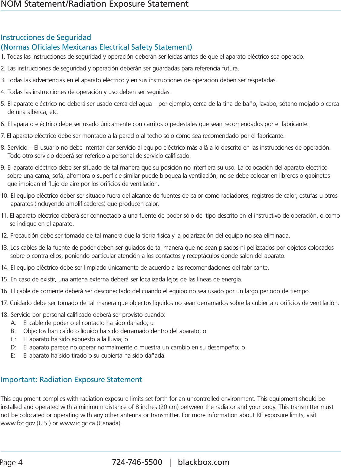
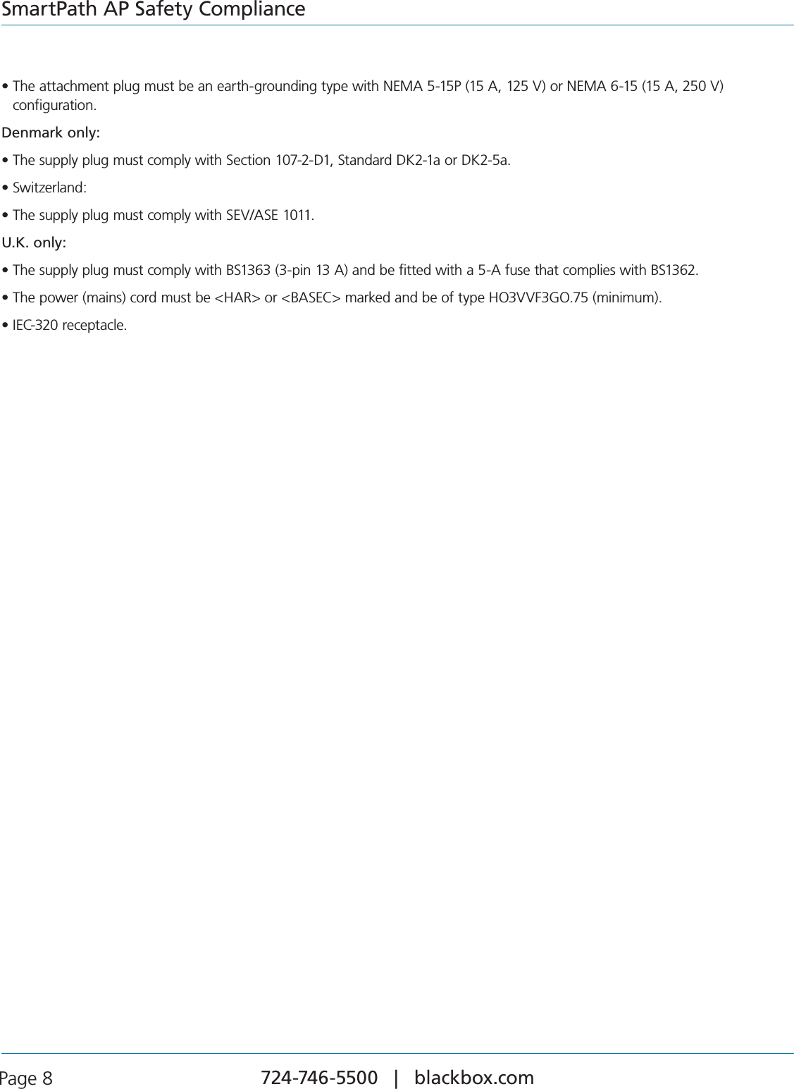
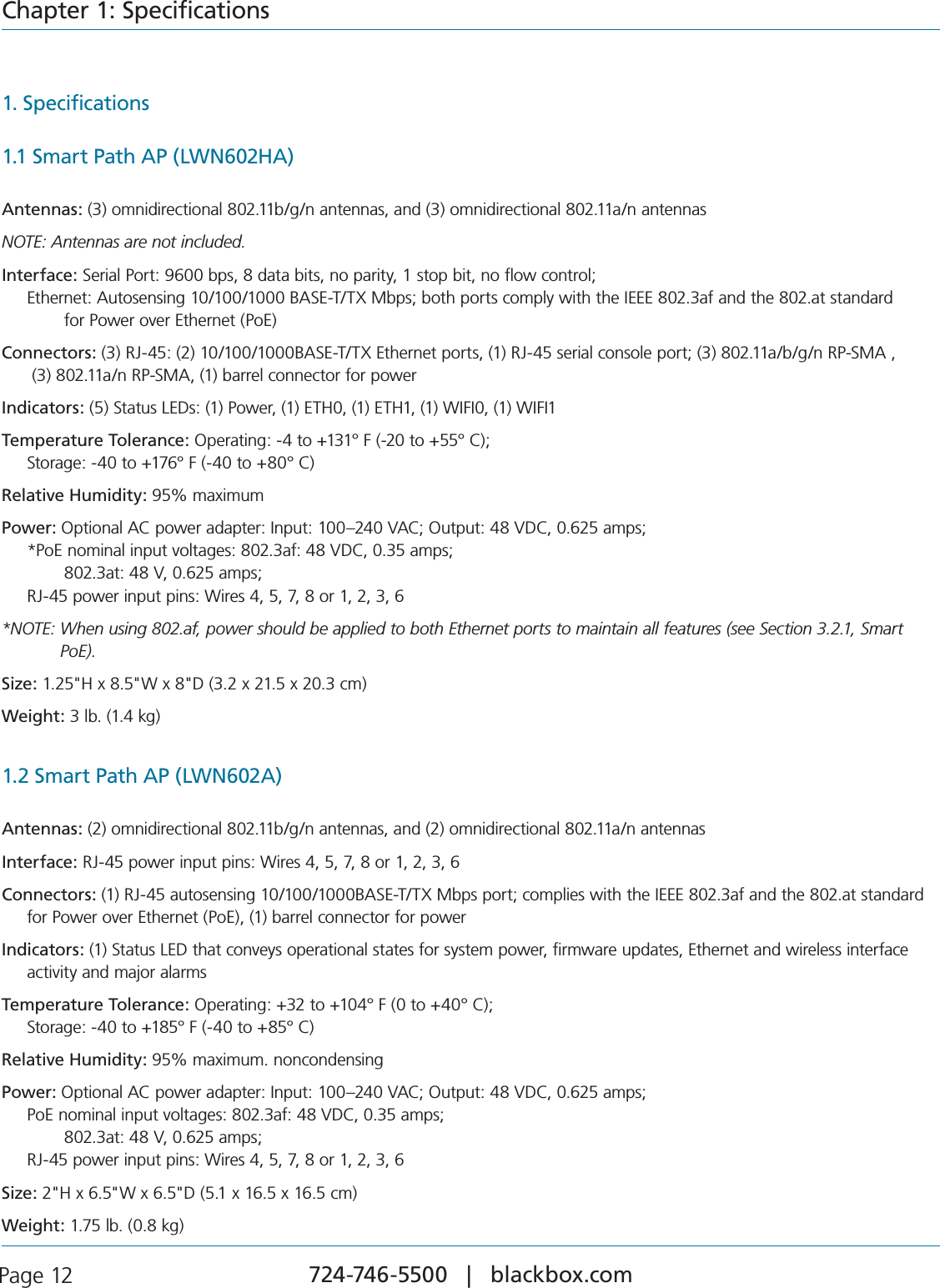
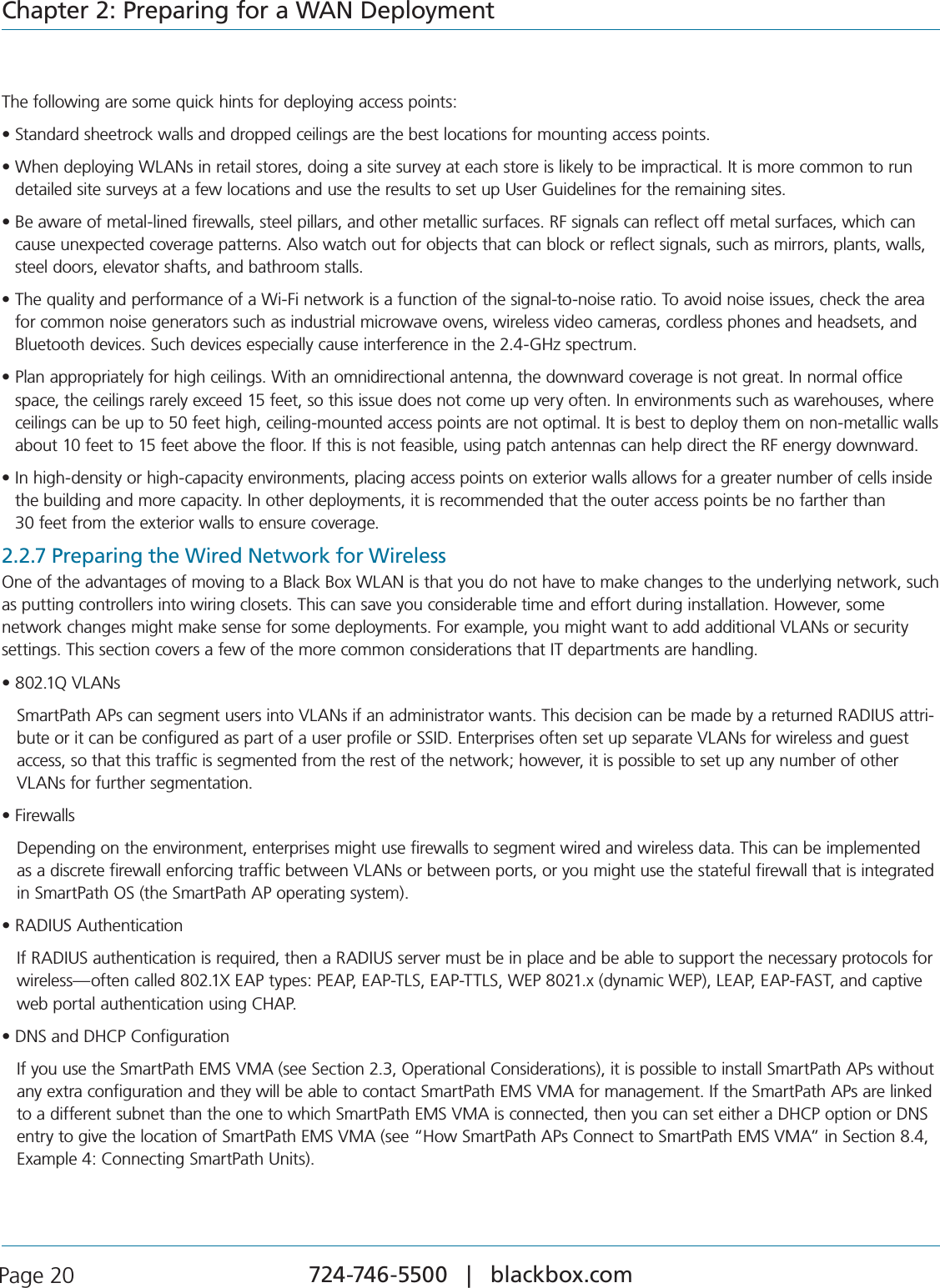
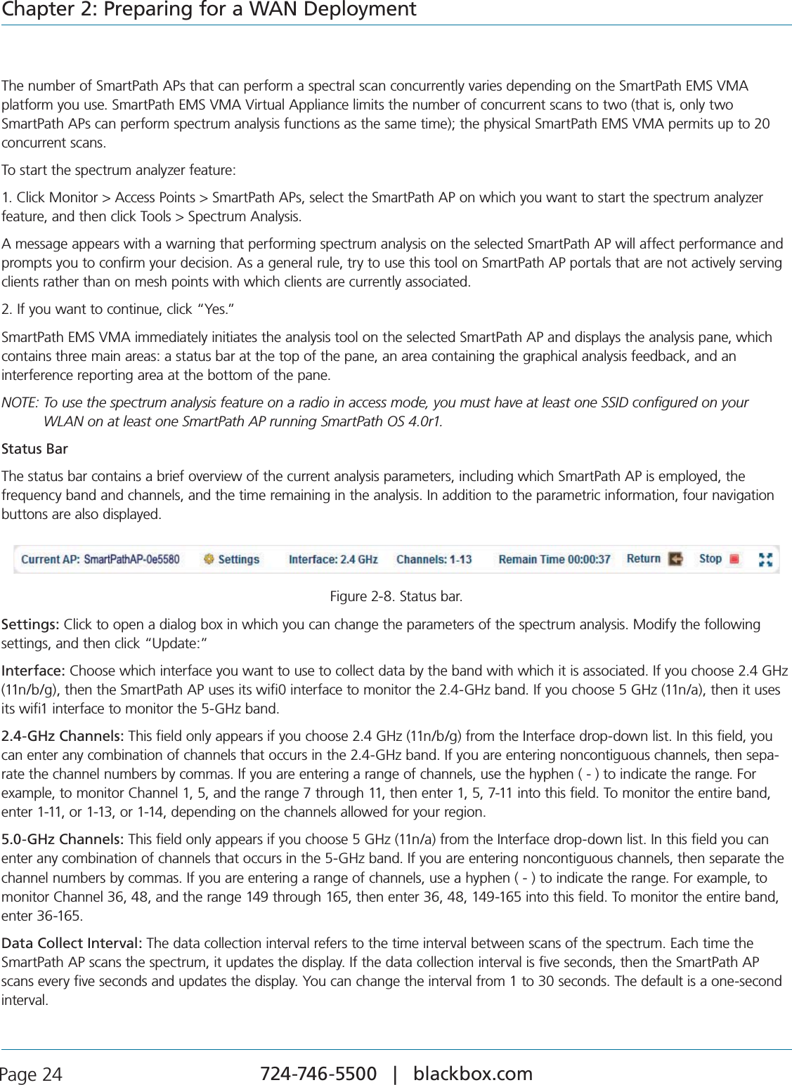
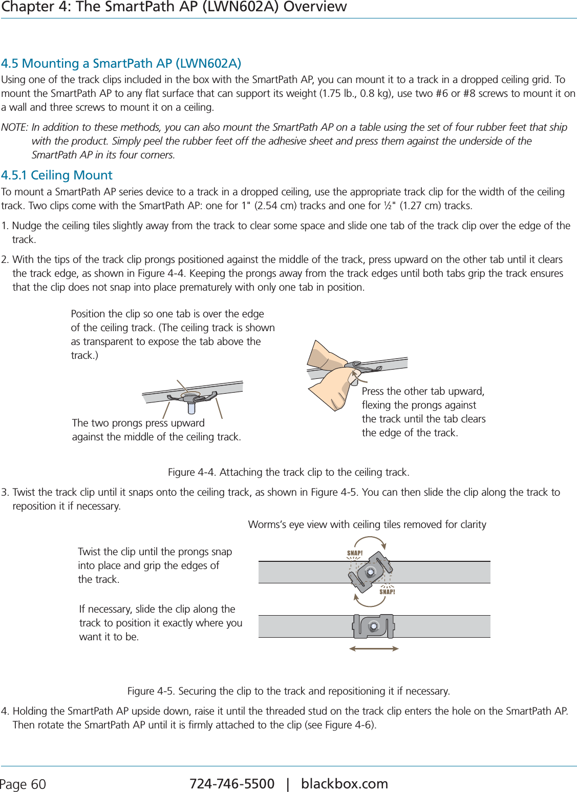
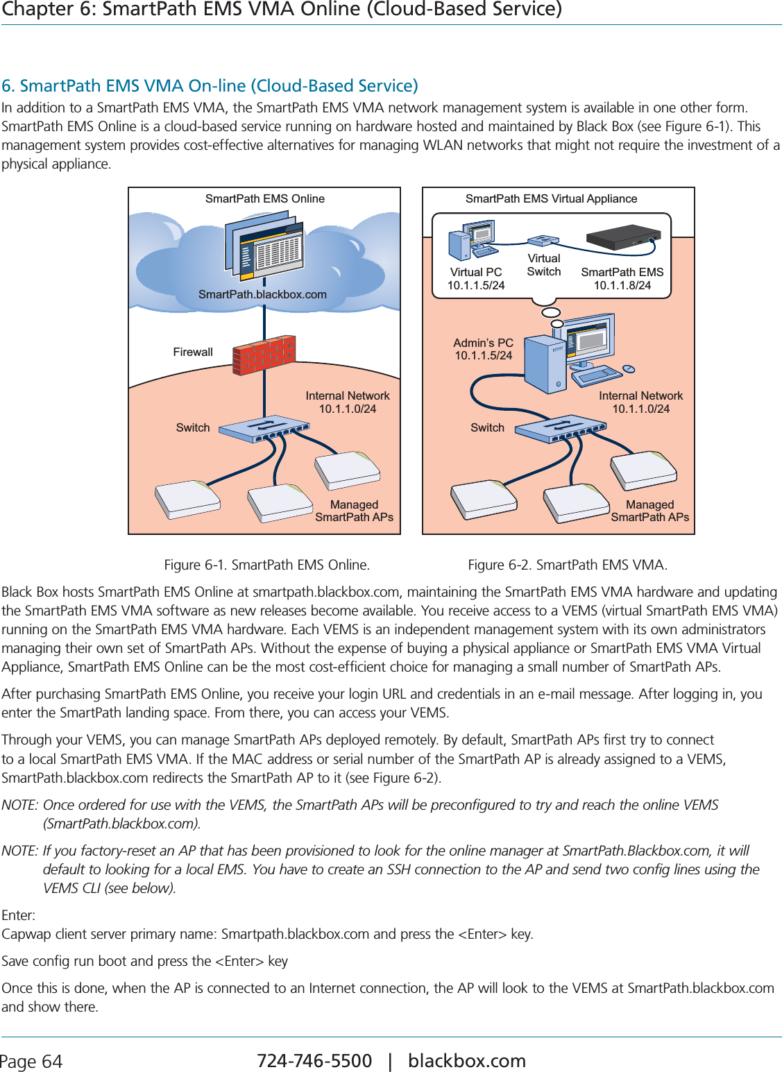
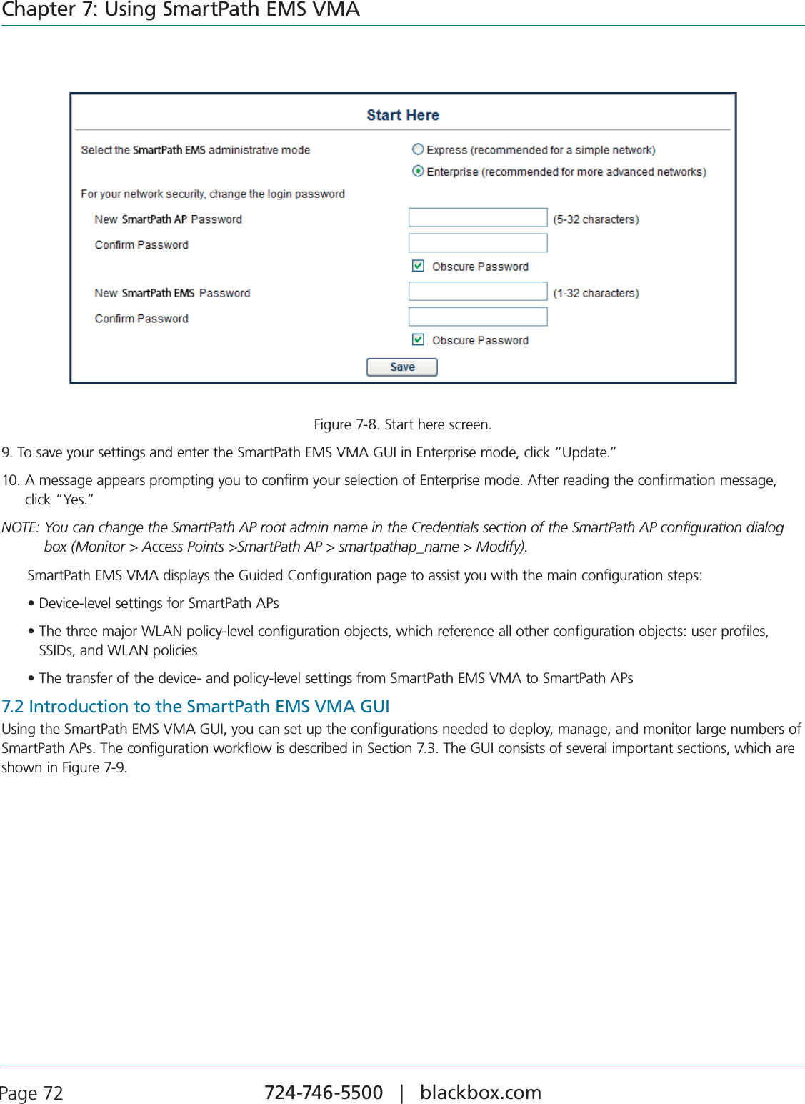
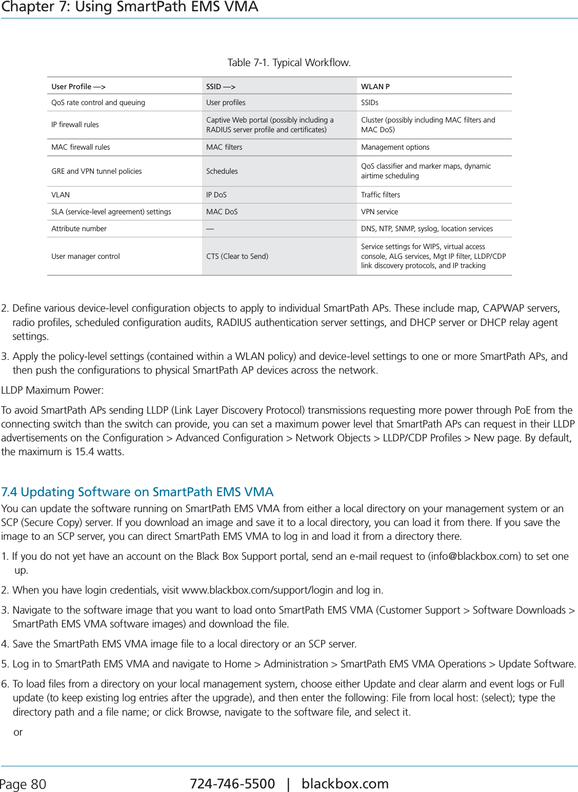
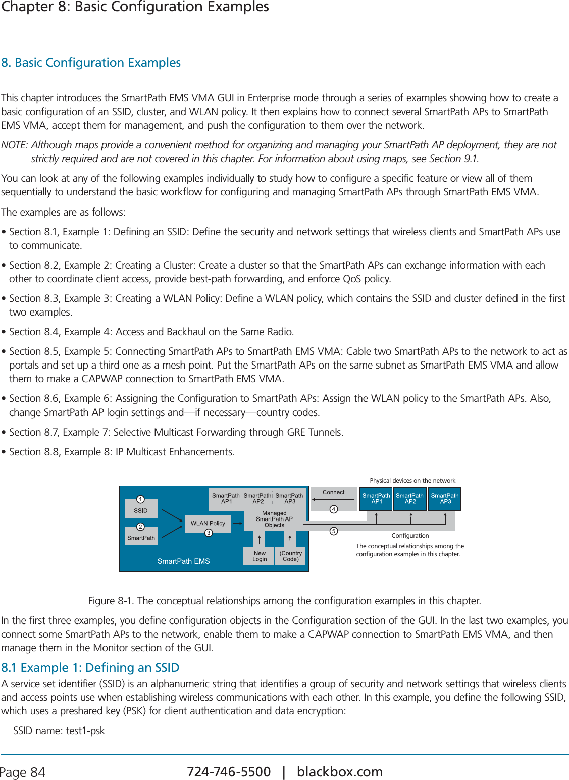
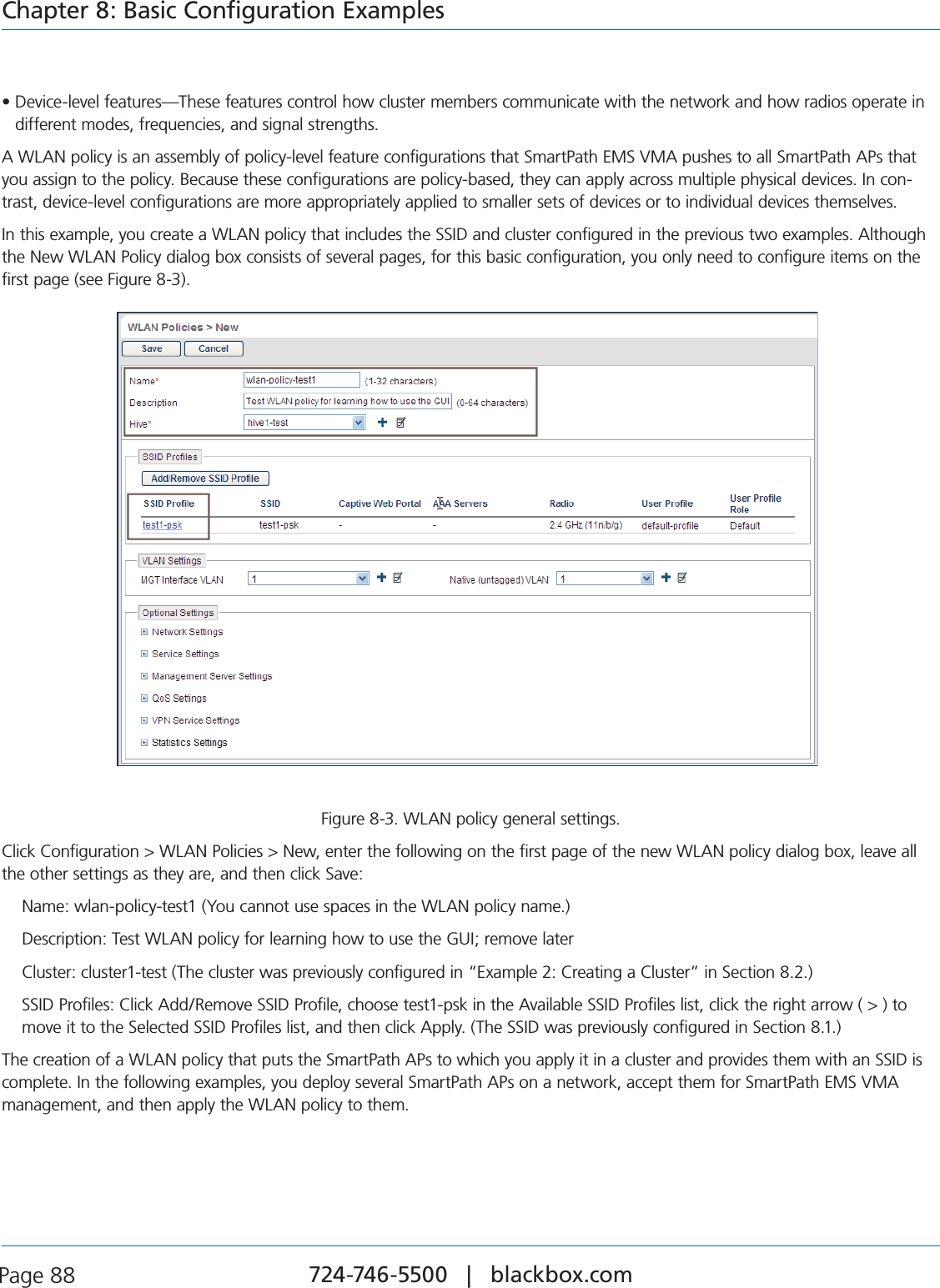
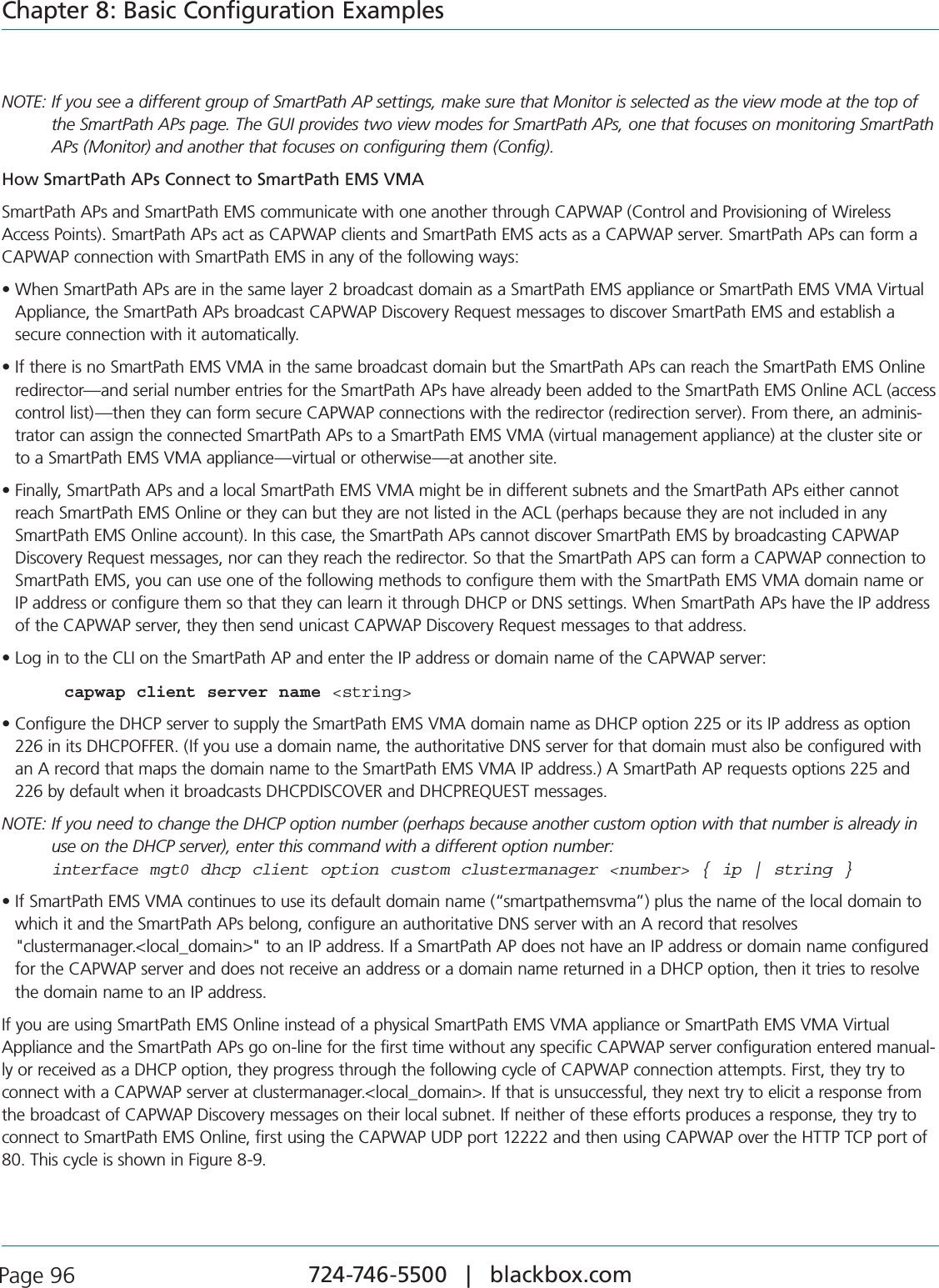
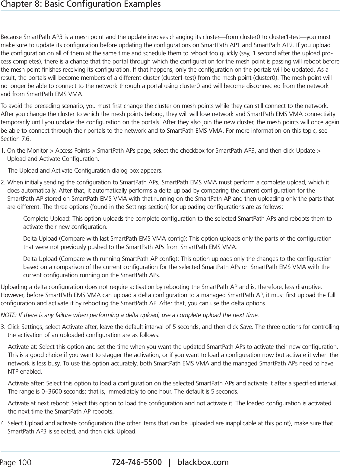
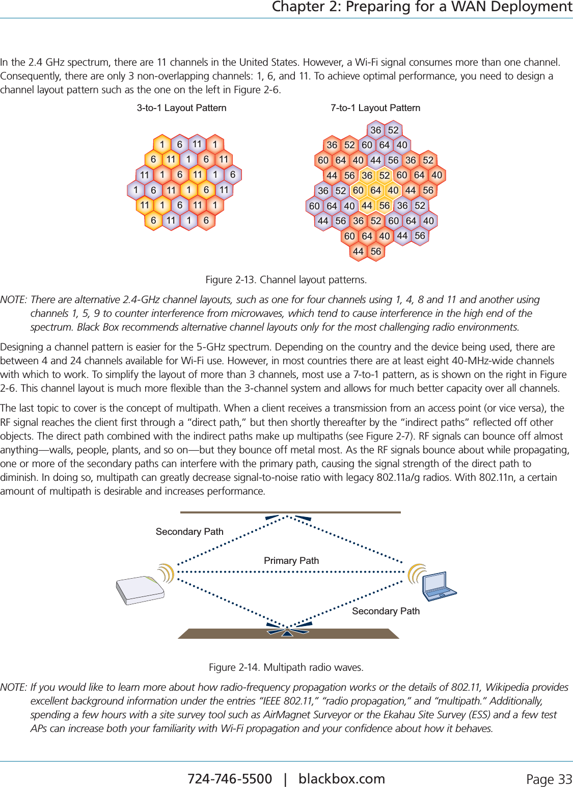
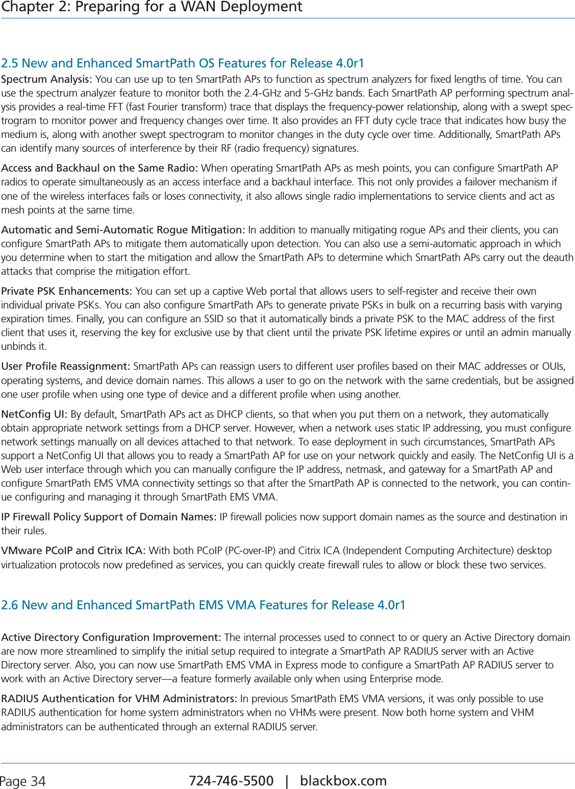
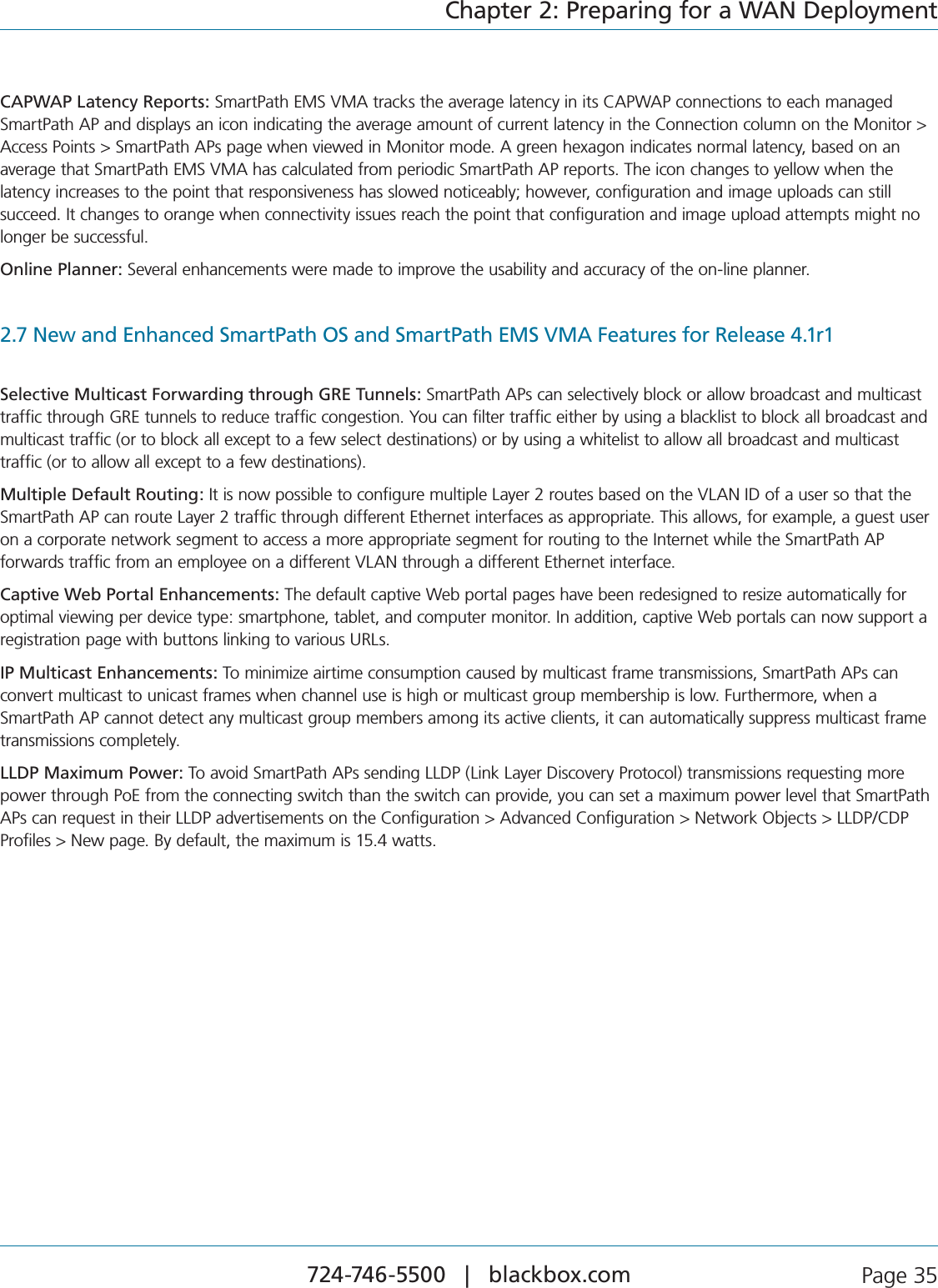
![724-746-5500 | blackbox.com Page 26Chapter 2: Preparing for a WAN DeploymentEach of the representations can be enlarged to fill the entire analysis pane to provide more detail or to increase its visibility, or be deleted from the array to simplify the display. To change the display in this manner, use the buttons in the upper right corner of each of the representations.Pause/Resume: You can suspend a trace by clicking the Pause button. When you click “Pause,” the button becomes a Resume button (right-pointing triangle). To resume the trace, click “Resume.” NOTE: Pausing one of the displays does not affect any of the other displays and does not stop the collection of data. When you resume a display, it returns to displaying data as if there were no interruption. Maximize: Click the Maximize button (four outward-pointing arrows). This causes the small display to enlarge to fill the entire content pane of the page. This is distinct from the Maximize button on the status bar, which maximizes the content pane to fill the browser. To return to the smaller view, click the Restore Down button. This causes the display to return to the previous arrangement. Close: When you click the Close [ x ] button, the affected display disappears and the neighboring display expands to fill the vacated area. To recover a closed display, navigate away from the spectrum analysis page and then return to it. When you return, SmartPath EMS VMA again organizes the display in its default arrangement. A description of each of the four graphical representations of the RF environment follows: Real-time FFT: The real-time FFT is a trace that indicates the power of a signal (vertical axis) along a domain of frequencies (horizontal axis). The term FFT (fast Fourier transform) refers to the mathematical algorithm used to decompose received signals into their component’s frequencies. Within this display, there are two traces: the red trace indicates the real-time power levels, whereas the gray trace indicates the maximum power level reached during the current data collection session. On maximizing this display, you gain access to the following additional display parameters: Band: You can choose which band you want to monitor in this display: 2.400-2.500 GHz, 5.150-5.350 GHz, 5.470-5.725 GHz, or 5.725-5.850 GHz. Channels: Choose one of the channel combinations in the drop-down list to display channel boundaries within the graph. Center: Use this control to scroll the graph right or left. You can use the Center control in combination with the Span control to zoom in on a specific area of the frequency domain. Span: This control establishes the width of the viewable area, effectively zooming in on the center frequency. Use this control with the Center control to zoom in on a specific area of the frequency domain. Reference Level: By default, the reference level of the graph (the top line) is 0 dBm. When used with the Vertical Scale control, you can zoom in on a specific portion of the actual trace.By changing the reference level using this control, you can also view very low power levels near the noise floor. In a very quiet environment, the noise floor is generally between -130 dBm and -90 dBm; in very noisy or busy environments, it is much higher. Vertical Scale: The vertical scale of a graph indicates how much vertical distance on the graph corresponds to power. By default, the vertical scale is set to 10 dB, which means that a power change of 10 dB corresponds to a specific, physical vertical distance on the graphic display. Changing that setting to 5 dB doubles the vertical resolution of the graph. Because there are many different sizes of monitors, the actual scale that you see in your browser is relative.Max Hold: By default, this check box is selected and SmartPath EMS VMA displays the gray trace that indicates the maximum power level reached during the current data collection session. To turn off the gray trace, clear the check box. FFT Duty Cycle: The FFT duty cycle is the amount of time as a percent of total time that the SmartPath AP receives a signal above 20 dB above the noise floor. FFT duty cycle is often referred to as channel utilization because it indicates to what extent a channel is actually in use in terms of the relative amount of time the signal is present (vertical axis). Within this display, there are two traces: the red trace indicates the real-time duty cycle, whereas the gray trace indicates the maximum duty cycle reached during this data collection session.](https://usermanual.wiki/Black-Box/LWN602WA.User-Manual/User-Guide-1818882-Page-26.png)
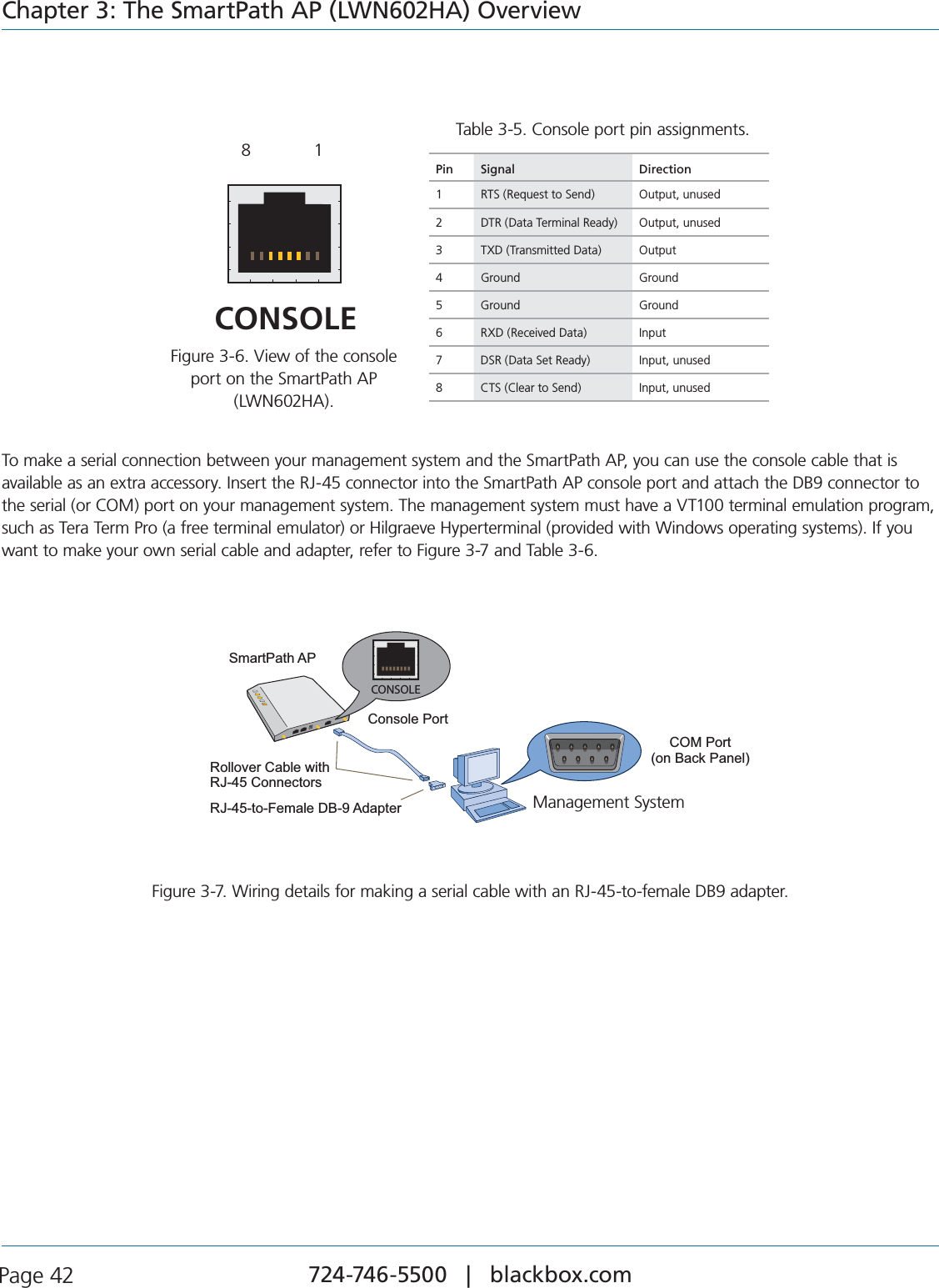
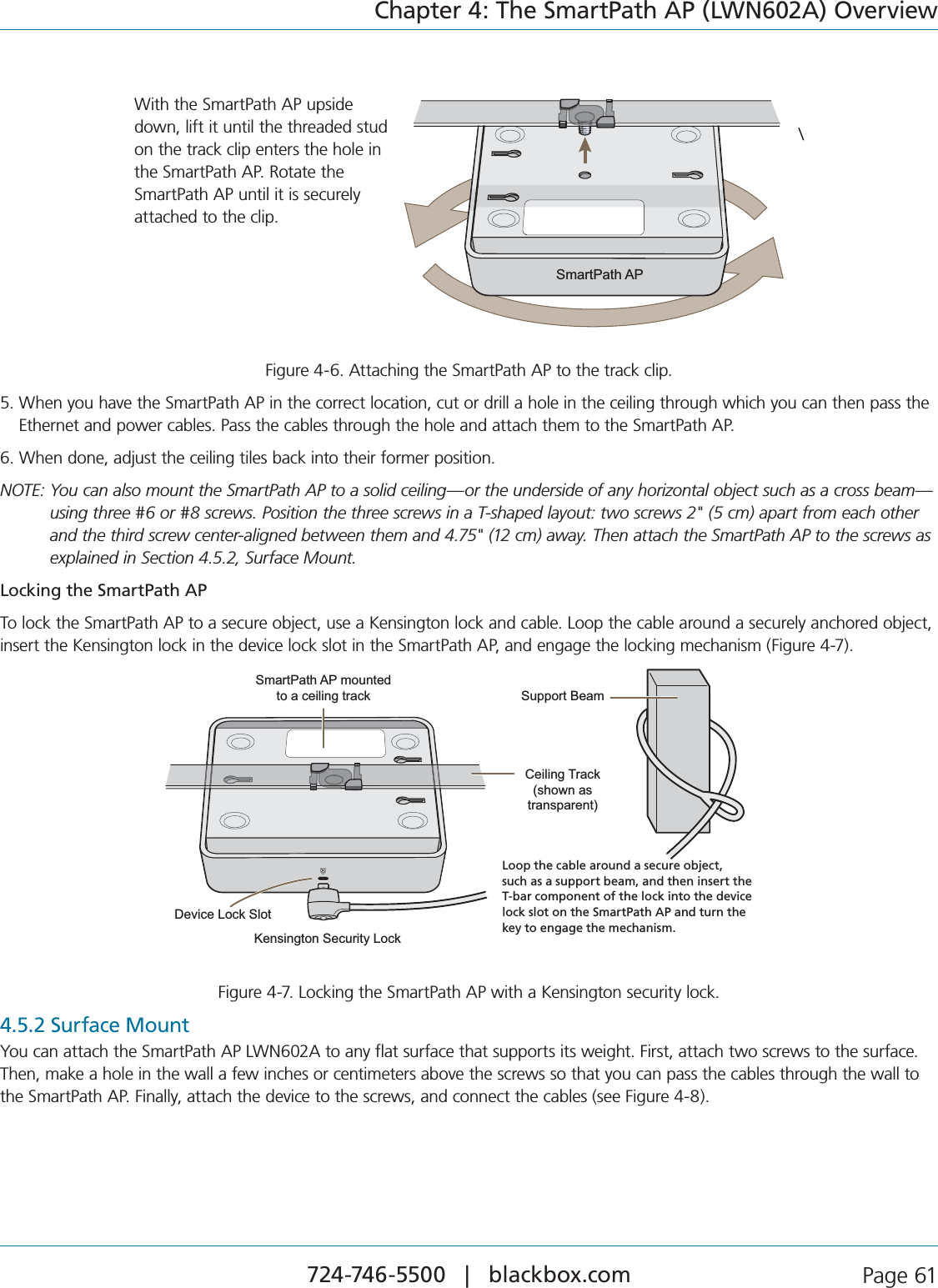
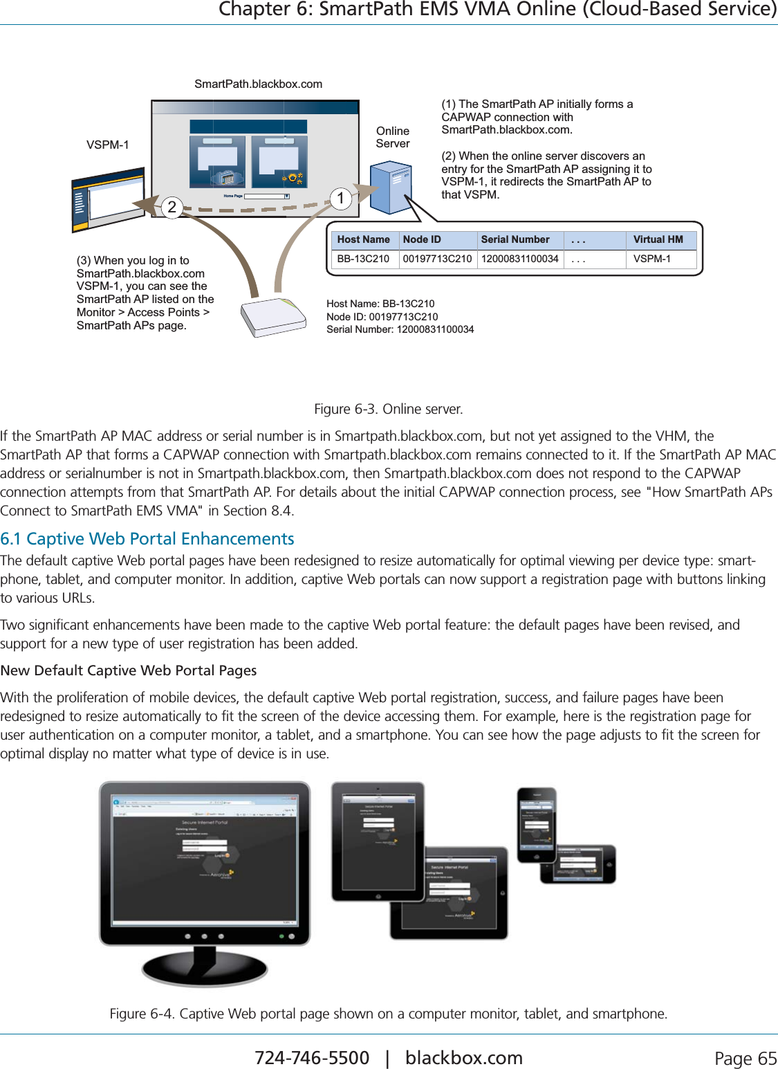
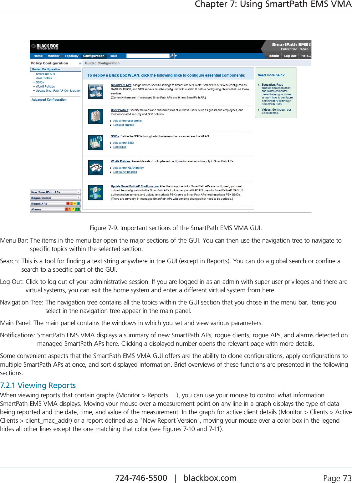
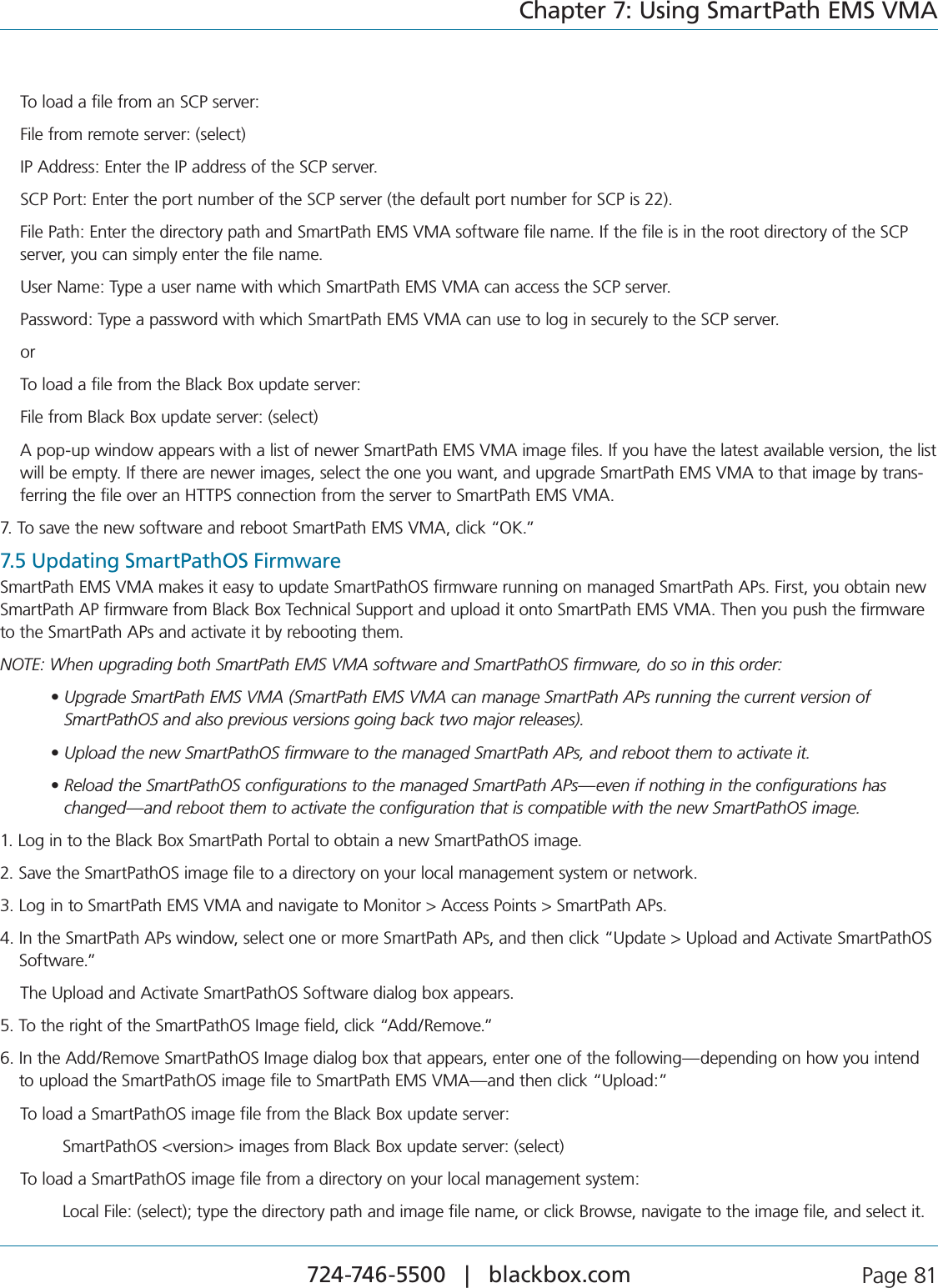
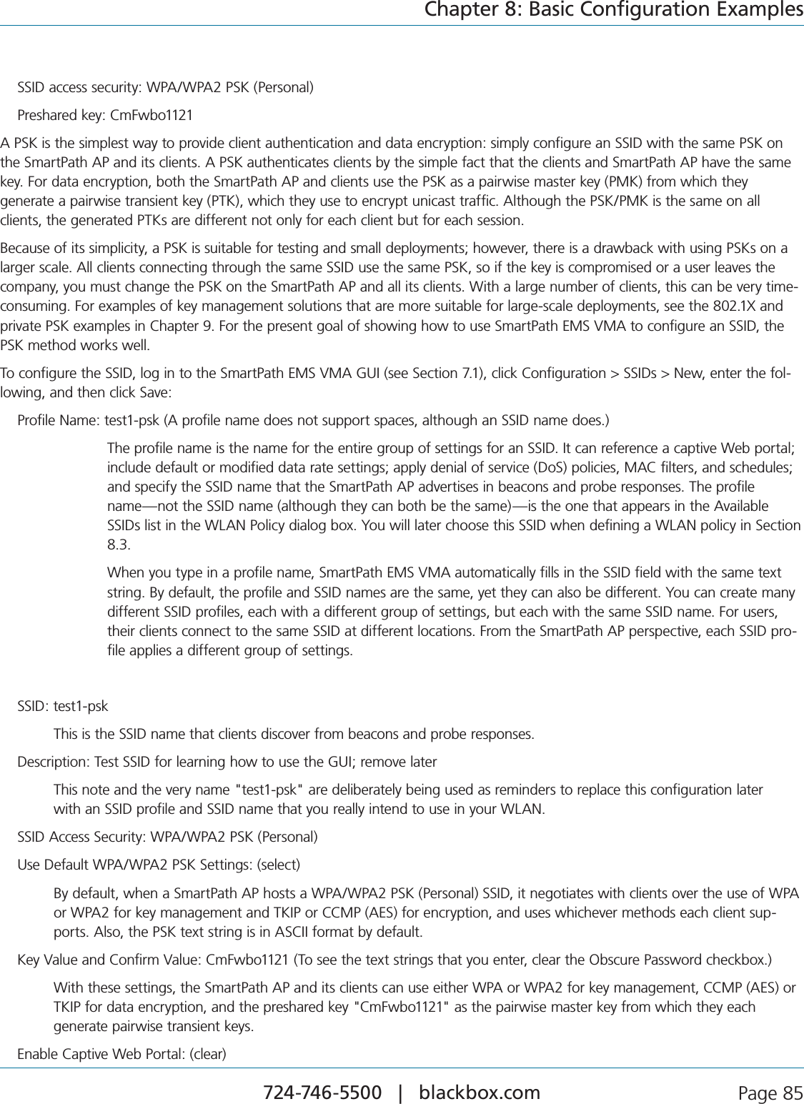
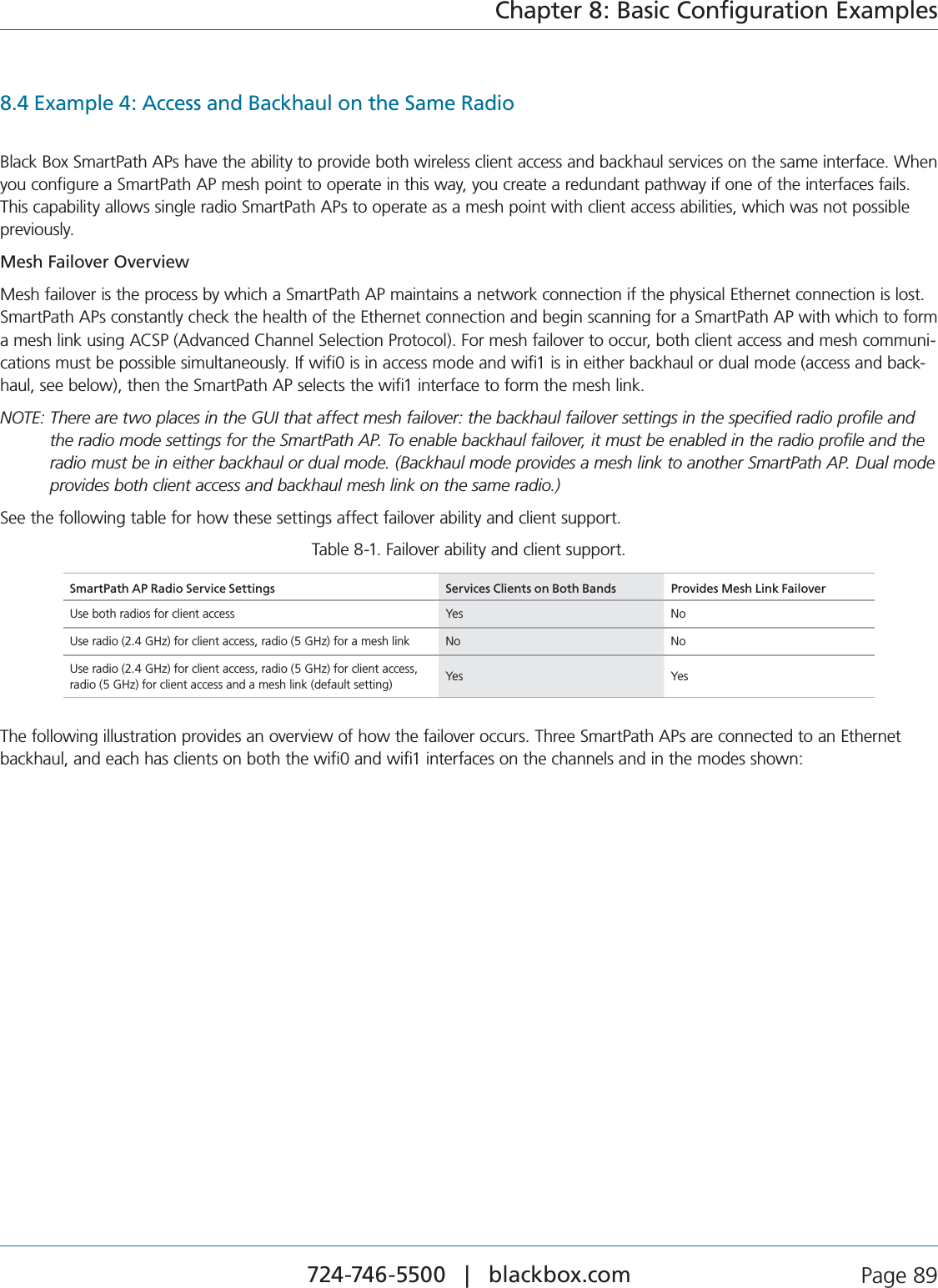
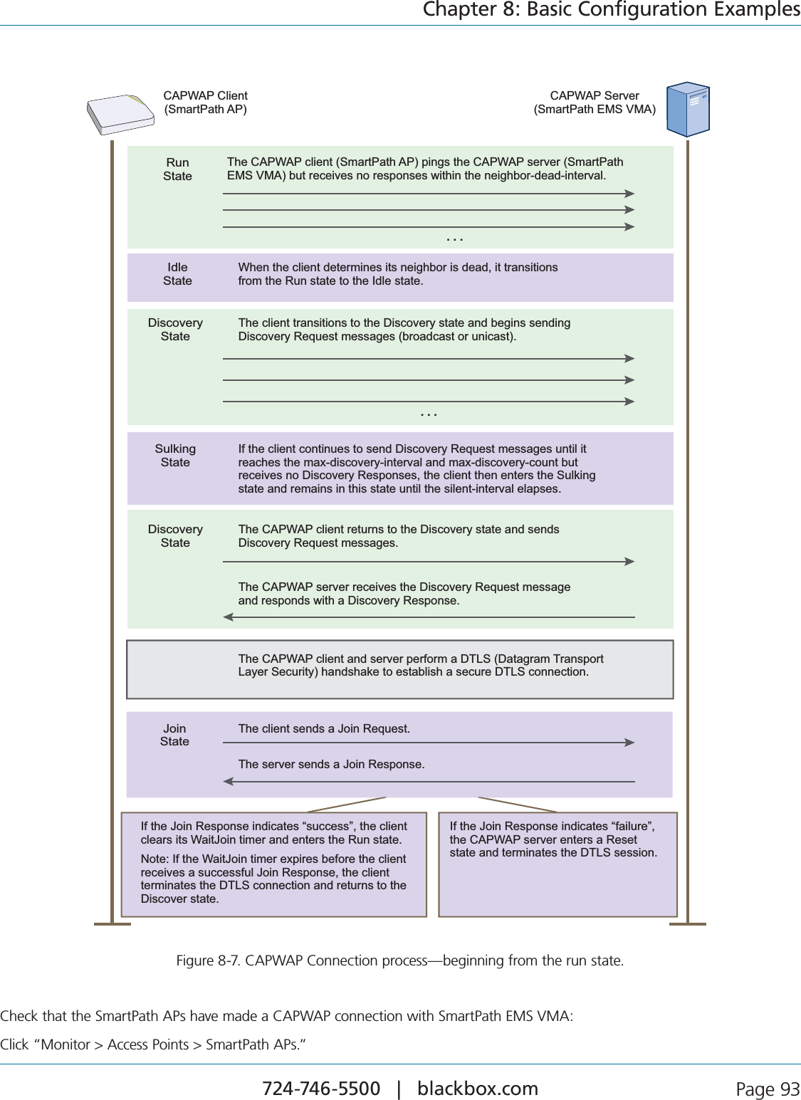
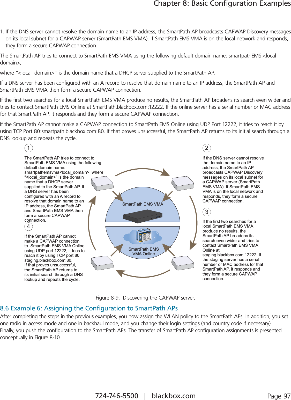
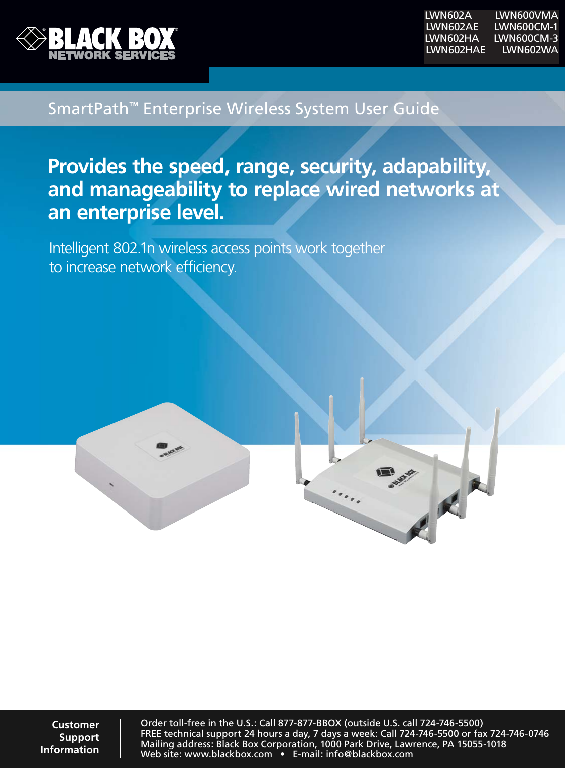
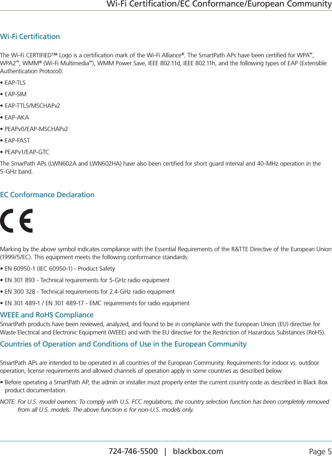
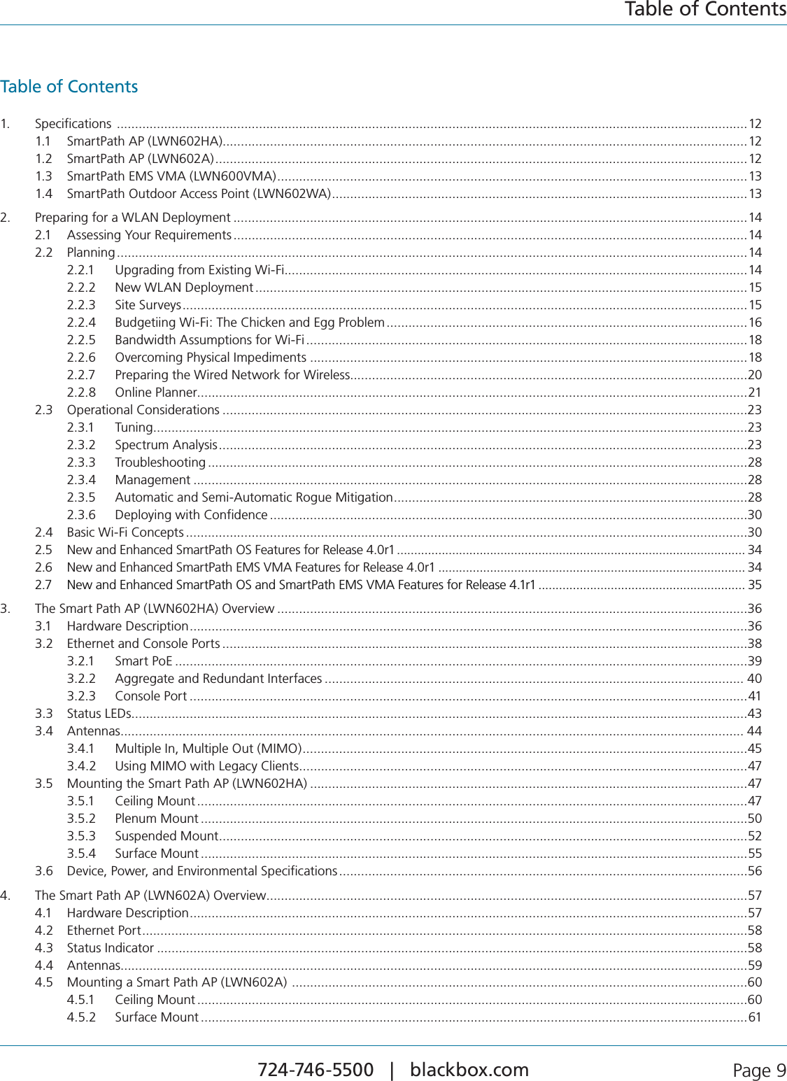
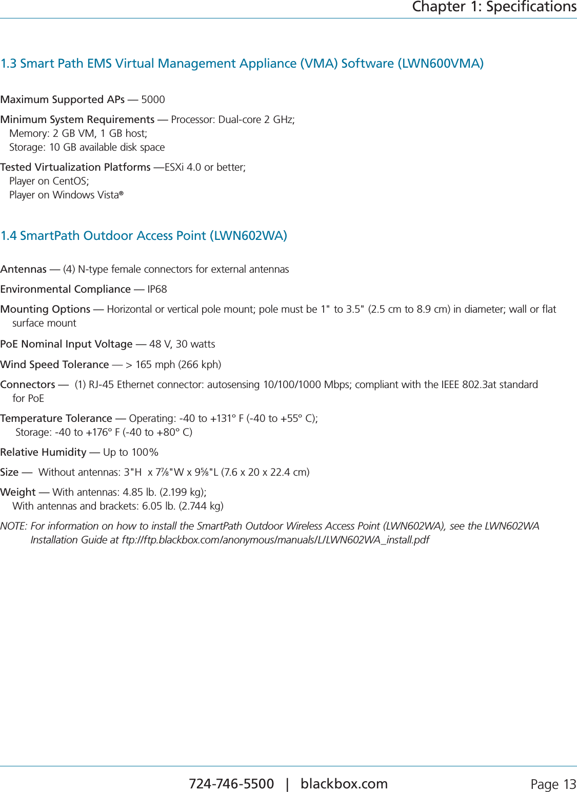
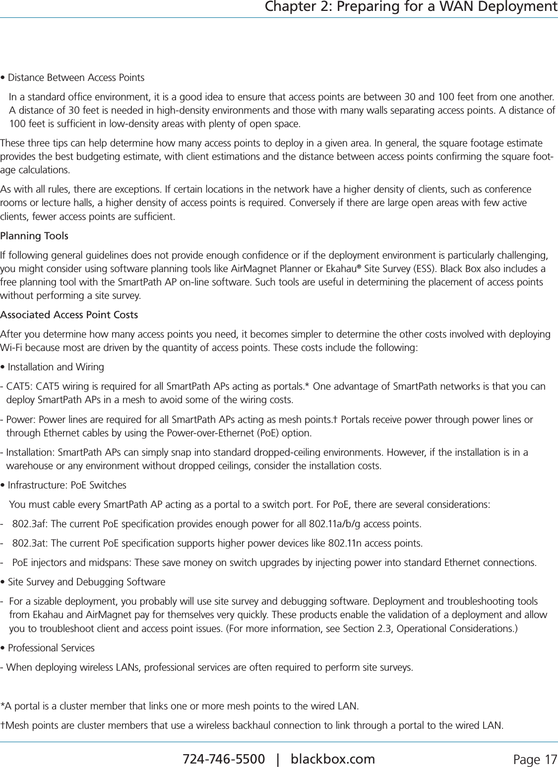
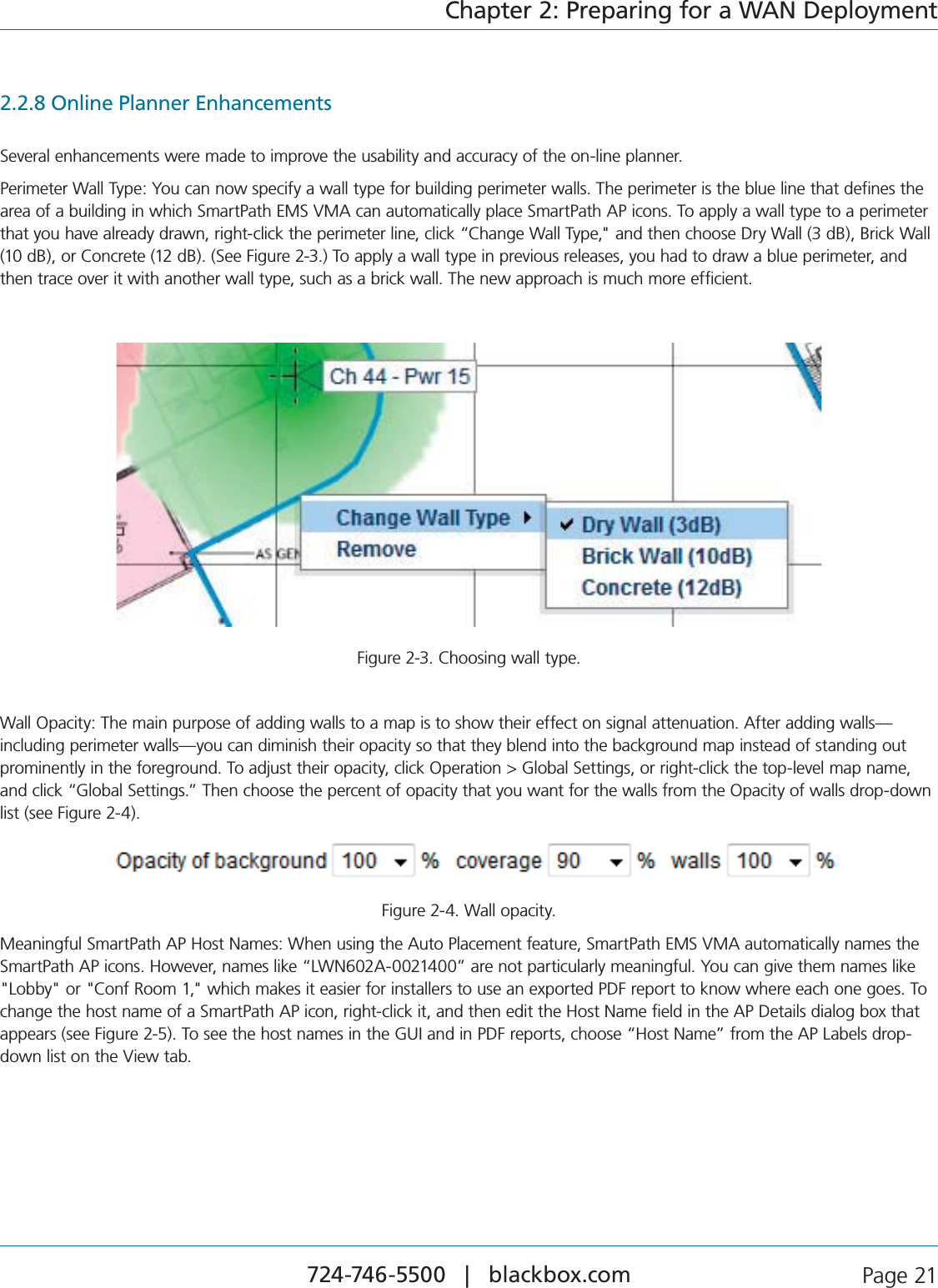
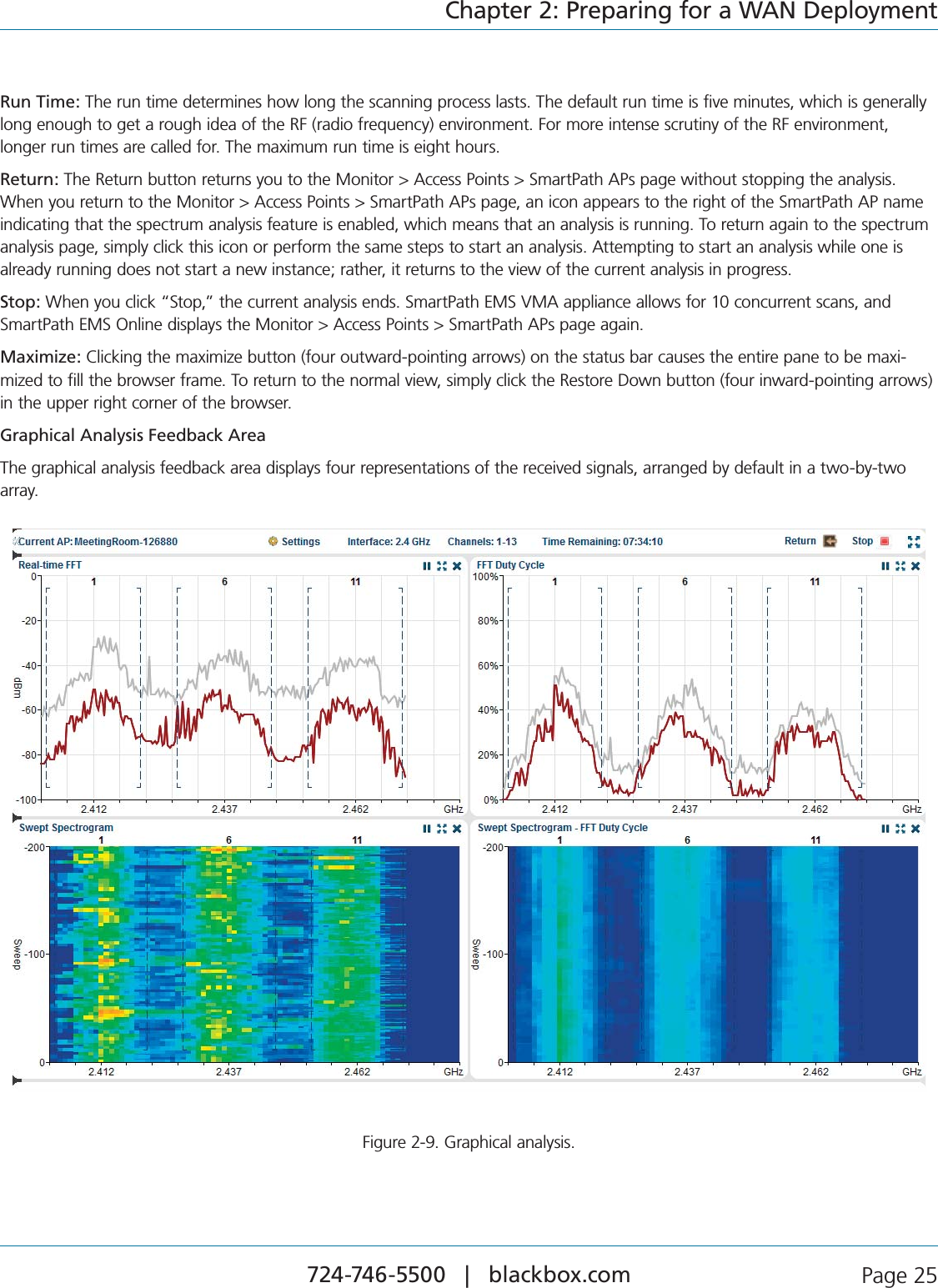
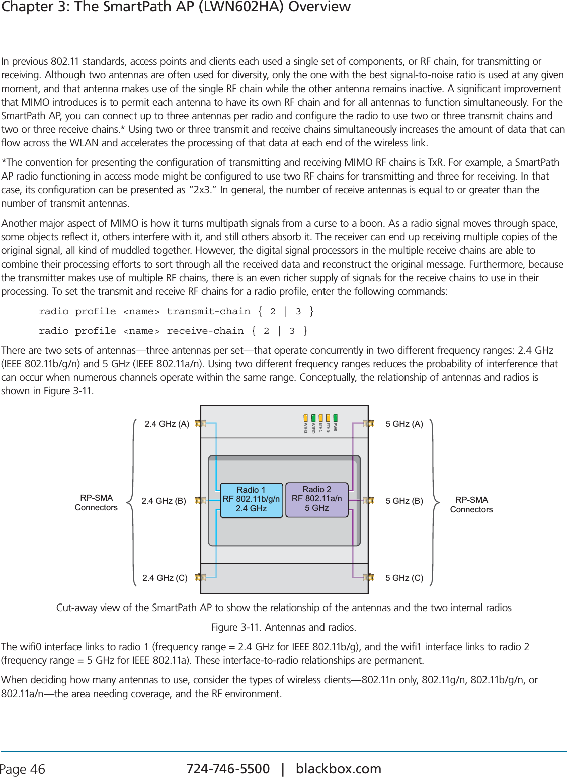
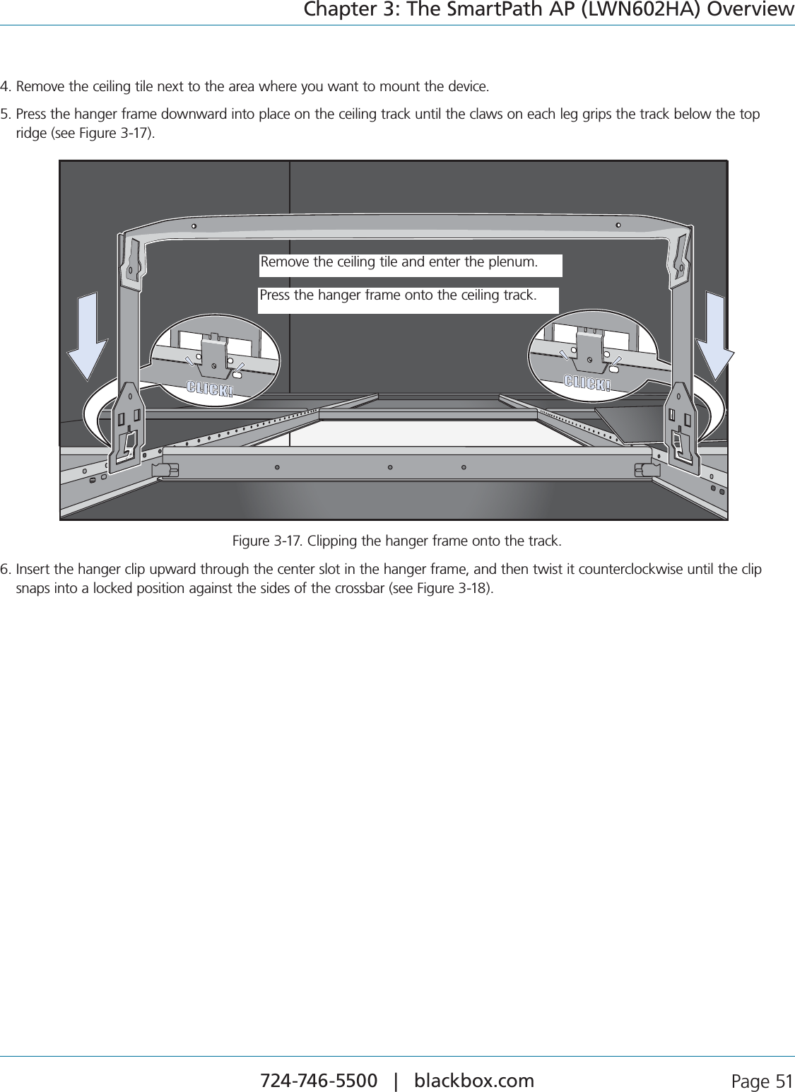
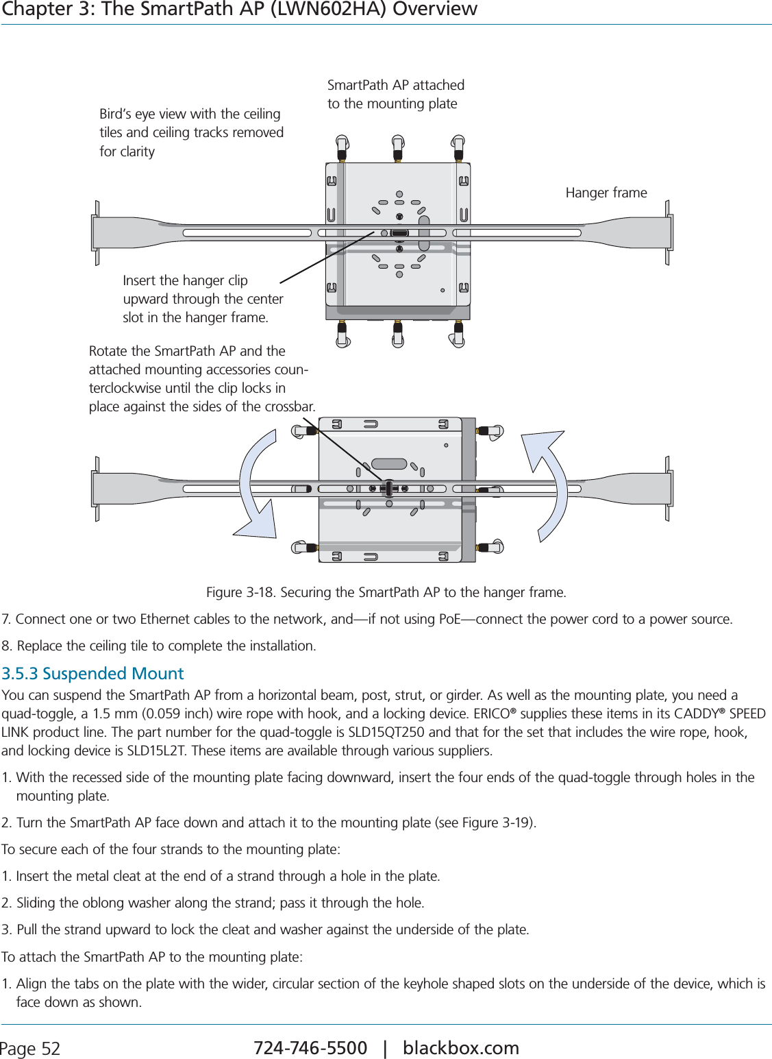
![724-746-5500 | blackbox.com Page 44Chapter 3: The SmartPath AP (LWN602HA) Overview3.4 AntennasAntennas are an integral part of the SmartPath AP. The SmartPath AP can accept up to six detachable dipole antennas. The three shorter antennas are designed for the 5-GHz band and have a 2-dBi gain. The three longer antennas are designed for the 2.4-GHz band and have a 4.9-dBi gain. These antennas are omnidirectional, providing fairly equal coverage in all directions in a toroidal (donut-shaped) pattern around each antenna (see Figure 2-1). For greater coverage on a horizontal plane, it is best to ori-ent the antennas vertically. So that you can easily do that whether the SmartPath AP chassis is mounted horizontally or vertically, the antennas hinge and swivel (see Figure 3-8).Although cluster members automatically adjust their signal strength according to their environments, you can resize the area of COVERAGEBYINCREASINGORDECREASINGTHESIGNALSTRENGTHMANUALLYBYENTERINGTHEINTERFACE[WIFI\WIFI]RADIOPOWERNUMBERCOMMANDWHERENUMBERCANBEFROMTOANDREPRESENTSAVALUEIND"M5 GHz Antenna for IEEE 802.11a/nLength when fully extended: 5 15/16” (15 cm)2.4 GHz Antenna for IEEE 802.11b/g/nLength when fully extended: 7 7/8” (20 cm)5-GHz Antenna for IEEE 802.11a/nLength when fully extended: 515⁄16" (15 cm)2.4-GHz Antenna for IEEE 802.11b/g/nLength when fully extended: 77⁄8" (20 cm)The base of the antennas hinge up to 90 degrees so that you can orient the antennas independently of the orientation of the SmartPath AP chassis. The antennas also rotate in a full circle.Figure 3-8. SmartPath AP (LWN602HA) antennas.](https://usermanual.wiki/Black-Box/LWN602WA.User-Manual/User-Guide-1818882-Page-44.png)
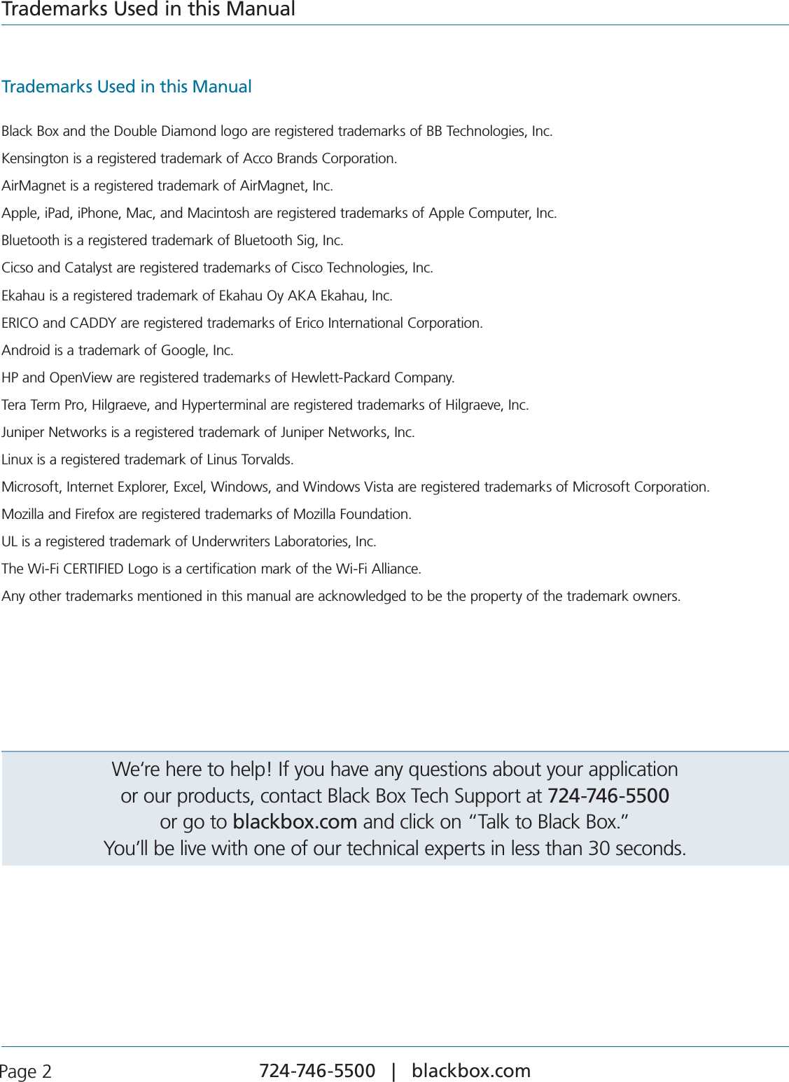
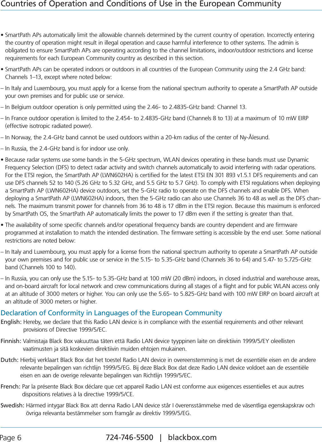
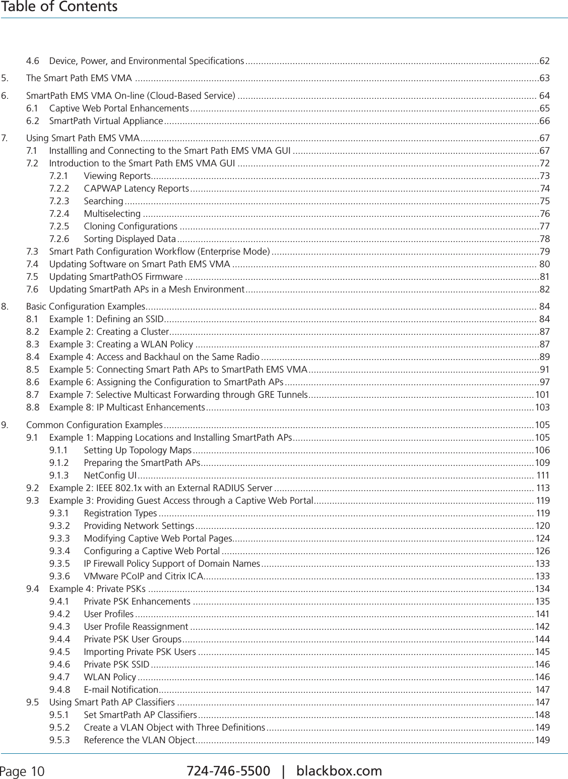
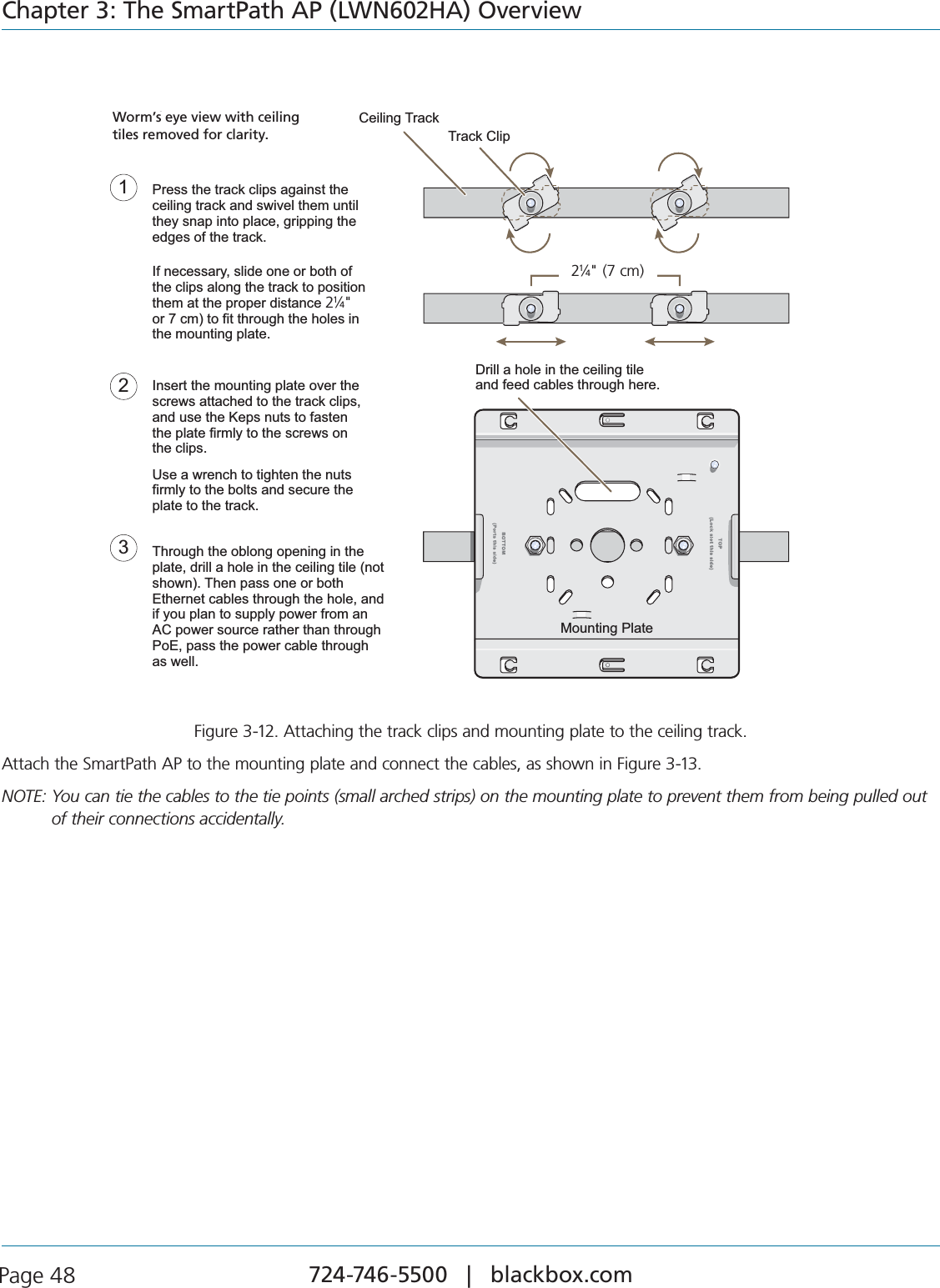
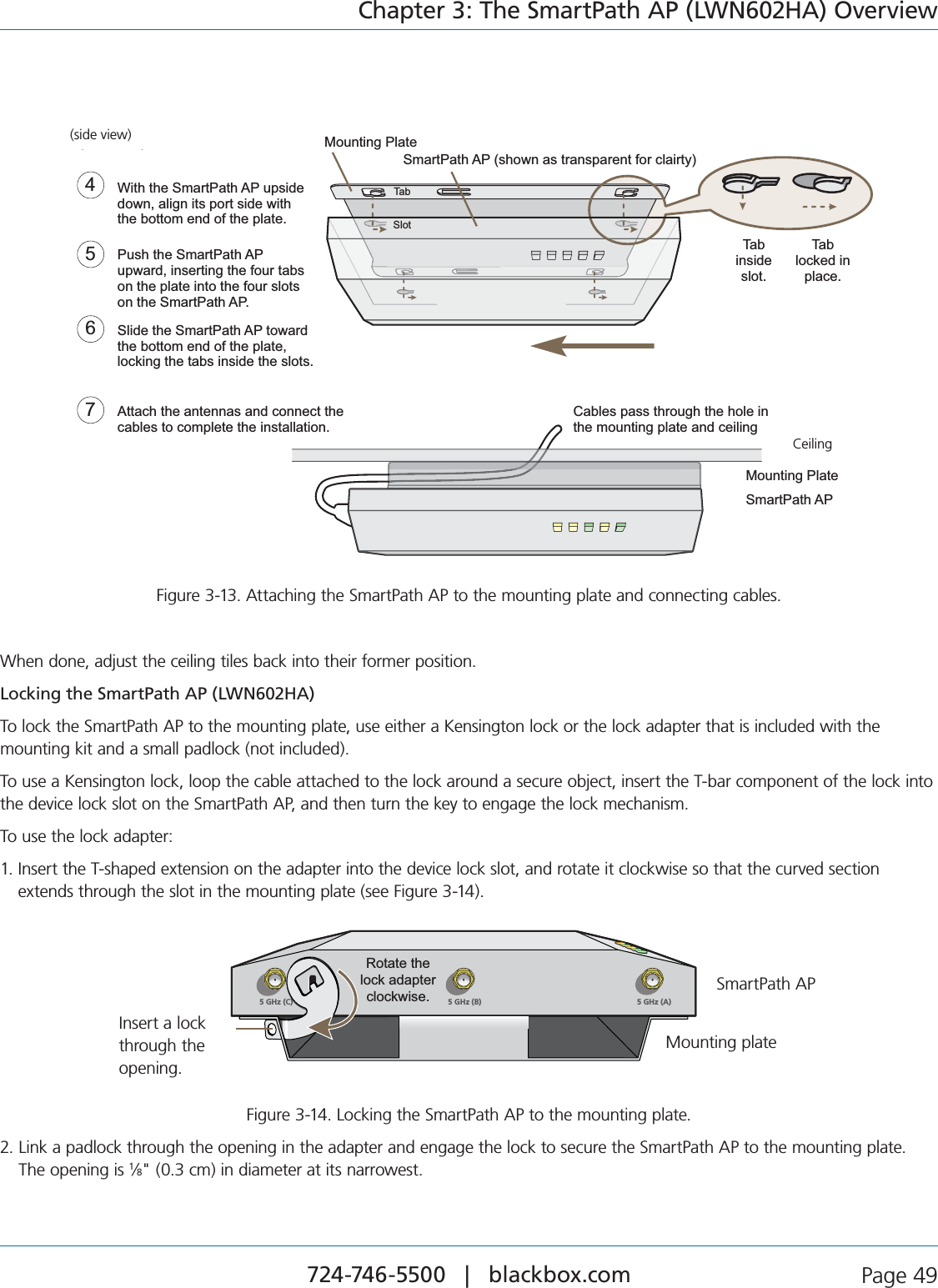
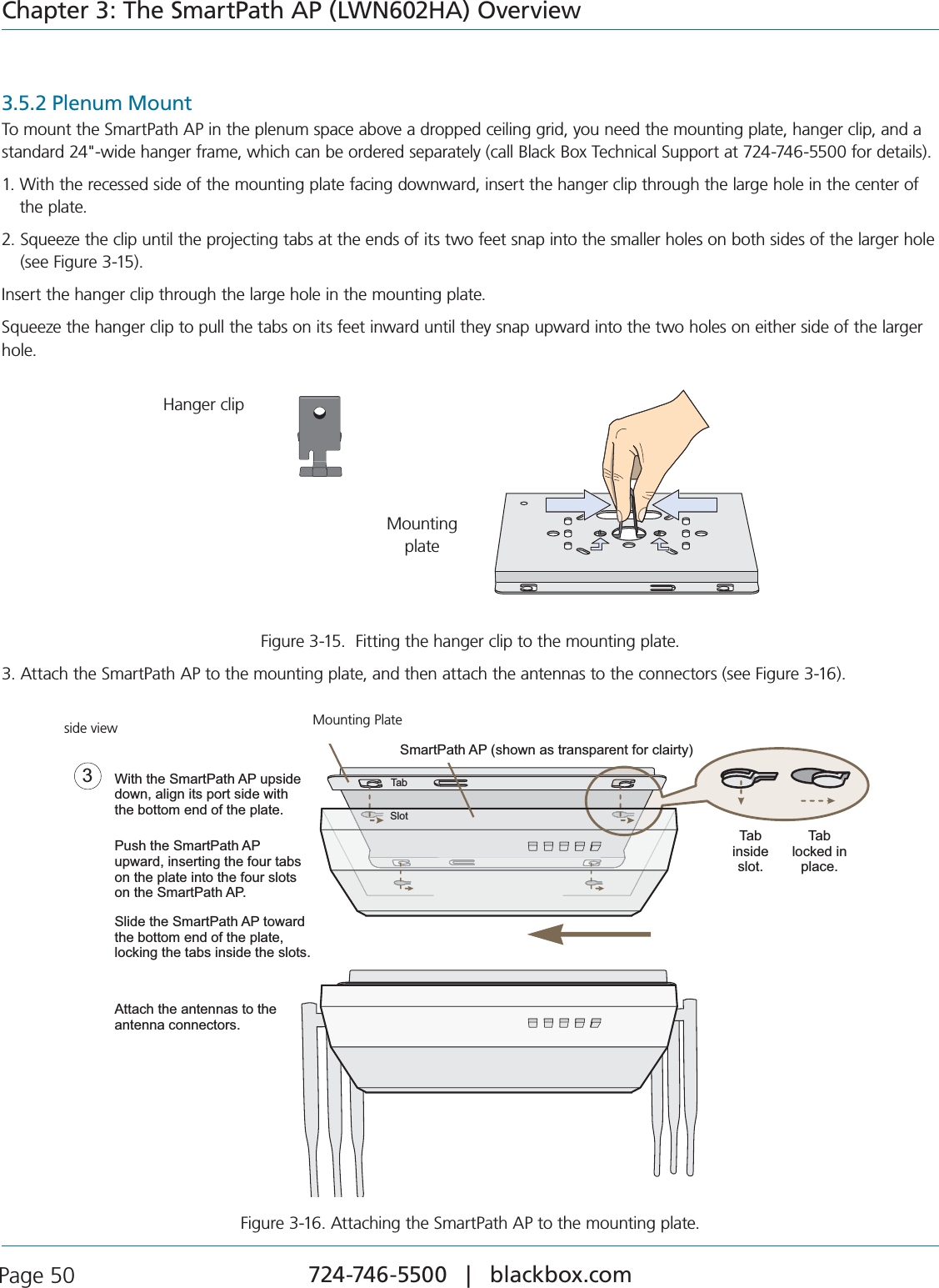
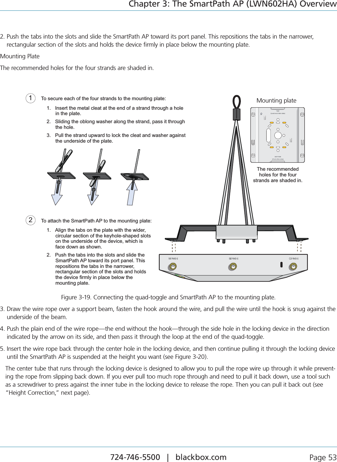
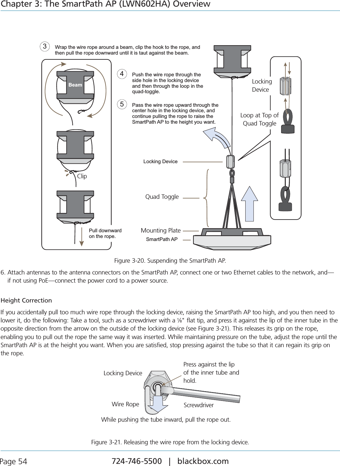
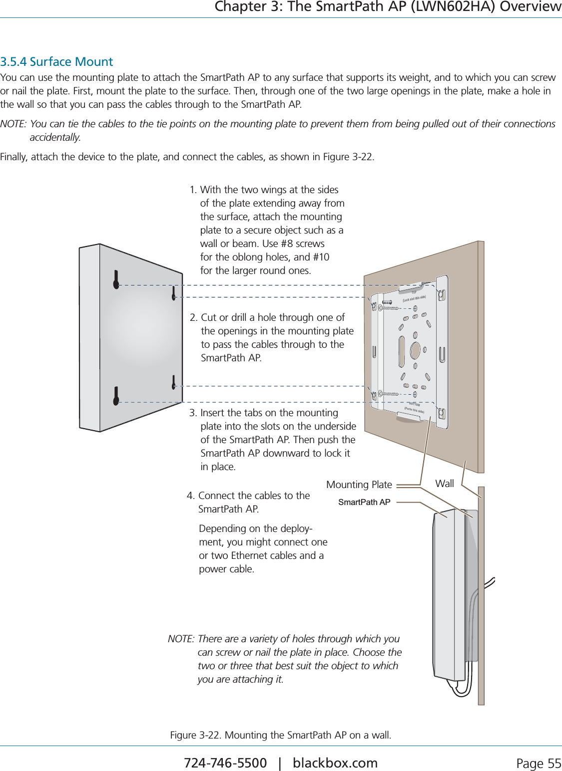
![724-746-5500 | blackbox.com Page 47Chapter 3: The SmartPath AP (LWN602HA) Overview3.4.2 Using MIMO with Legacy ClientsIn addition to supporting up to 300-Mbps throughput per radio for 802.11n clients, MIMO can improve the reliability and speed of legacy 802.11a/b/g client traffic. When an 802.11a/b/g access point does not receive acknowledgement that a frame it sent was received, it resends that frame, possibly at a somewhat lower transmission rate. If the access point must continue resending frames, it will continue lowering its transmission rate. As a result, clients that could get 54-Mbps throughput in an interference-free environment might have to drop to 48- or 36-Mbps speeds because of multipath interface. However, because MIMO technology makes better use of multipath, an access point using MIMO can continue transmitting at 54 Mbps, or at least at a better rate than it would in a pure 802.11a/b/g environment, thus improving the reliability and speed of 802.11a/b/g client traffic.Although 802.11a/b/g client traffic can benefit somewhat from an 802.11n access point using MIMO, supporting such legacy clients along with 802.11n clients can have a negative impact on 802.11n client traffic. Legacy clients take longer to send the same amount of data as 802.11n clients. Consequently, legacy clients consume more airtime than 802.11n clients do, causing greater congestion in the WLAN and reducing 802.11n performance.By default, the SmartPath AP supports 802.11a/b/g clients. You can restrict access only to clients using the IEEE 802.11n standard. By only allowing traffic from clients using 802.11n, you can increase the overall bandwidth capacity of the access point so that there will not be an impact on 802.11n clients during times of network congestion. To do that, enter the following command: radio profile <string> 11n-clients-onlyYou can also deny access just to clients using the IEEE 802.11b standard, which has the slowest data rates of the three legacy standards, while continuing to support 802.11a and 802.11g clients. To do that, enter the following command: no radio profile <string> allow-11b-clientsBy blocking access to 802.11b clients, their slower data rates cannot clog the WLAN when the amount of wireless traffic increases.3.5 Mounting the SmartPath AP (LWN602HA)Using the mounting plate and track clips, you can mount the SmartPath AP to the tracks of a dropped ceiling grid. Using just the mounting plate, you can mount the SmartPath AP to any surface that can support its weight (3.3 lb., 1.5 kg).This document covers the following methods for mounting the SmartPath AP (LWN602HA):s3ECTION#EILING-OUNT5SINGTHEMOUNTINGPLATEANDTRACKCLIPSYOUCANMOUNTTHE3MART0ATH!0TOTHETRACKSOFAdropped ceiling grid so that it is suspended upside down against the ceiling.s3ECTION0LENUM-OUNT5SINGTHEMOUNTINGPLATEHANGERCLIPANDHANGERFRAMEYOUCANMOUNTITINTHEPLENUMabove a dropped ceiling.s3ECTION3USPENDED-OUNT5SINGTHEMOUNTINGPLATECABLEQUADTOGGLEANDLOCKINGDEVICEYOUCANSUSPENDTHEdevice from a beam, bracket, or any object that can support its weight (3.3 lb. [1.5 kg]).s3ECTION3URFACE-OUNT5SINGJUSTTHEMOUNTINGPLATEANDSOMESCREWSORNAILSYOUCANMOUNTTHE3MART0ATH!0directly to any surface that can support its weight.NOTE: In addition to these methods, you can also mount the SmartPath AP on a table using the set of four rubber feet that ship with the product. Simply peel the rubber feet off the adhesive sheet and press them against the underside of the SmartPath AP in its four corners.3.5.1 Ceiling MountTo mount the SmartPath AP to a standard 1"-wide track in a dropped ceiling, you need the mounting plate, two track clips, and two Keps nuts that ship with the SmartPath AP. You also need a drill, a wrench, and—most likely—a ladder. Nudge the ceiling tiles slightly away from the track to clear some space. Attach the track clips to the ceiling track, and then fasten the mounting plate to the clips, as shown in Figure 3-12. When you have the mounting plate in the correct location, cut or drill a hole in the ceiling. Use it to pass through the Ethernet and power cables.](https://usermanual.wiki/Black-Box/LWN602WA.User-Manual/User-Guide-1818882-Page-47.png)
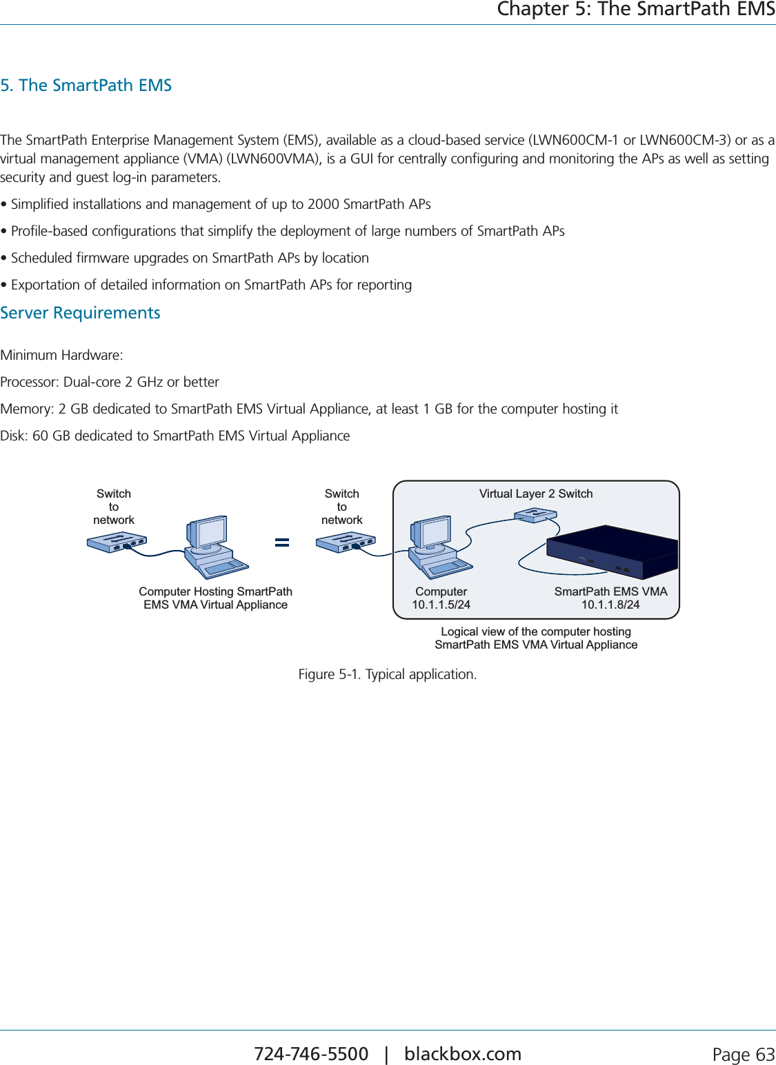
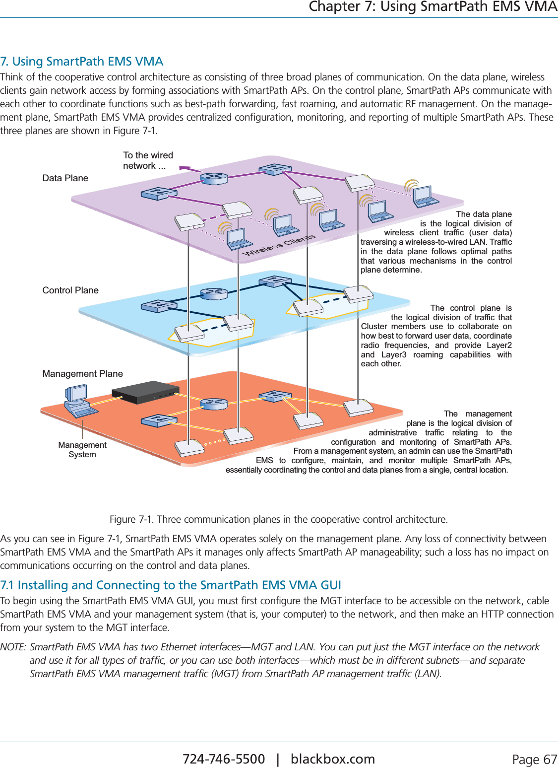
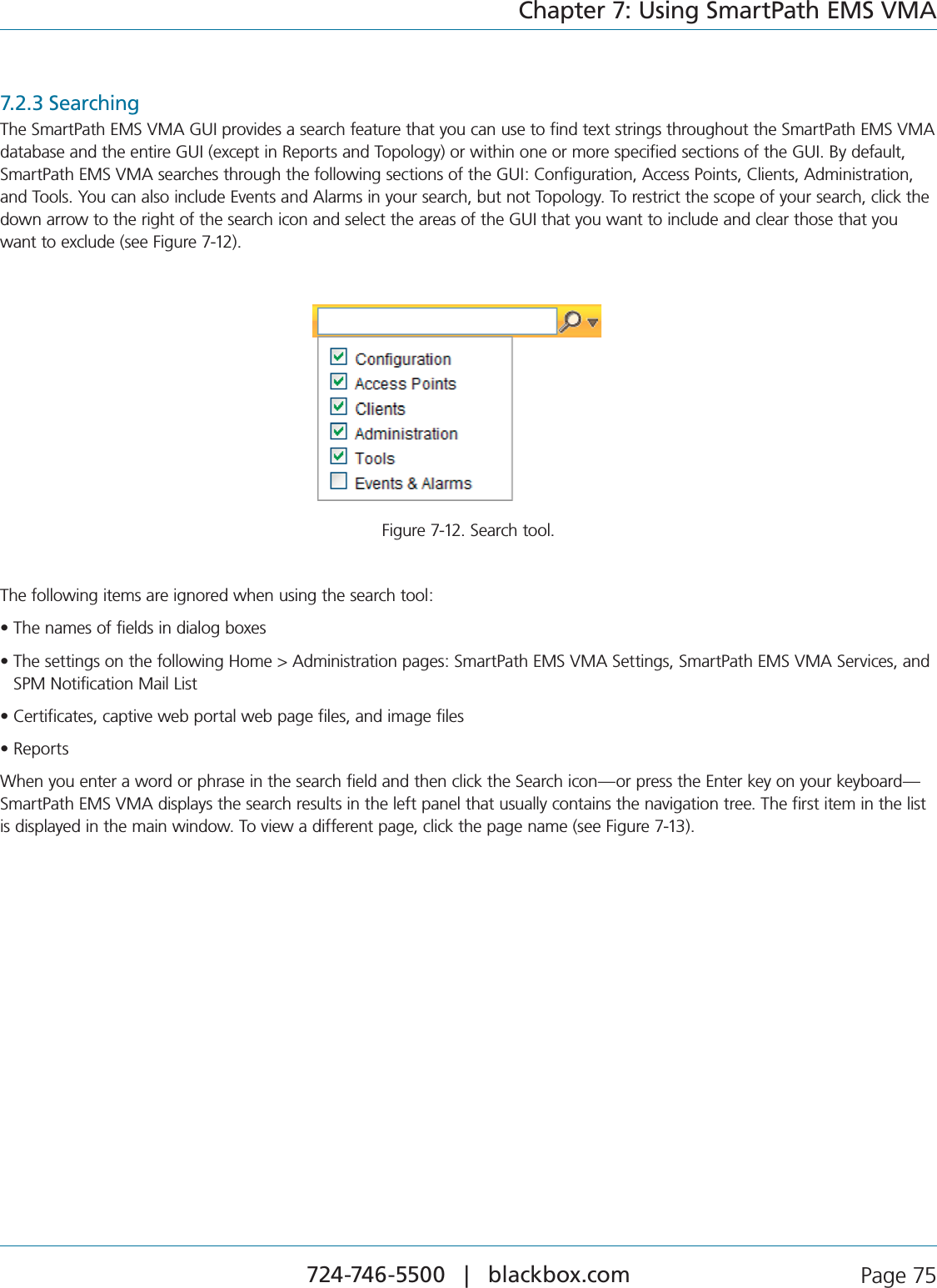
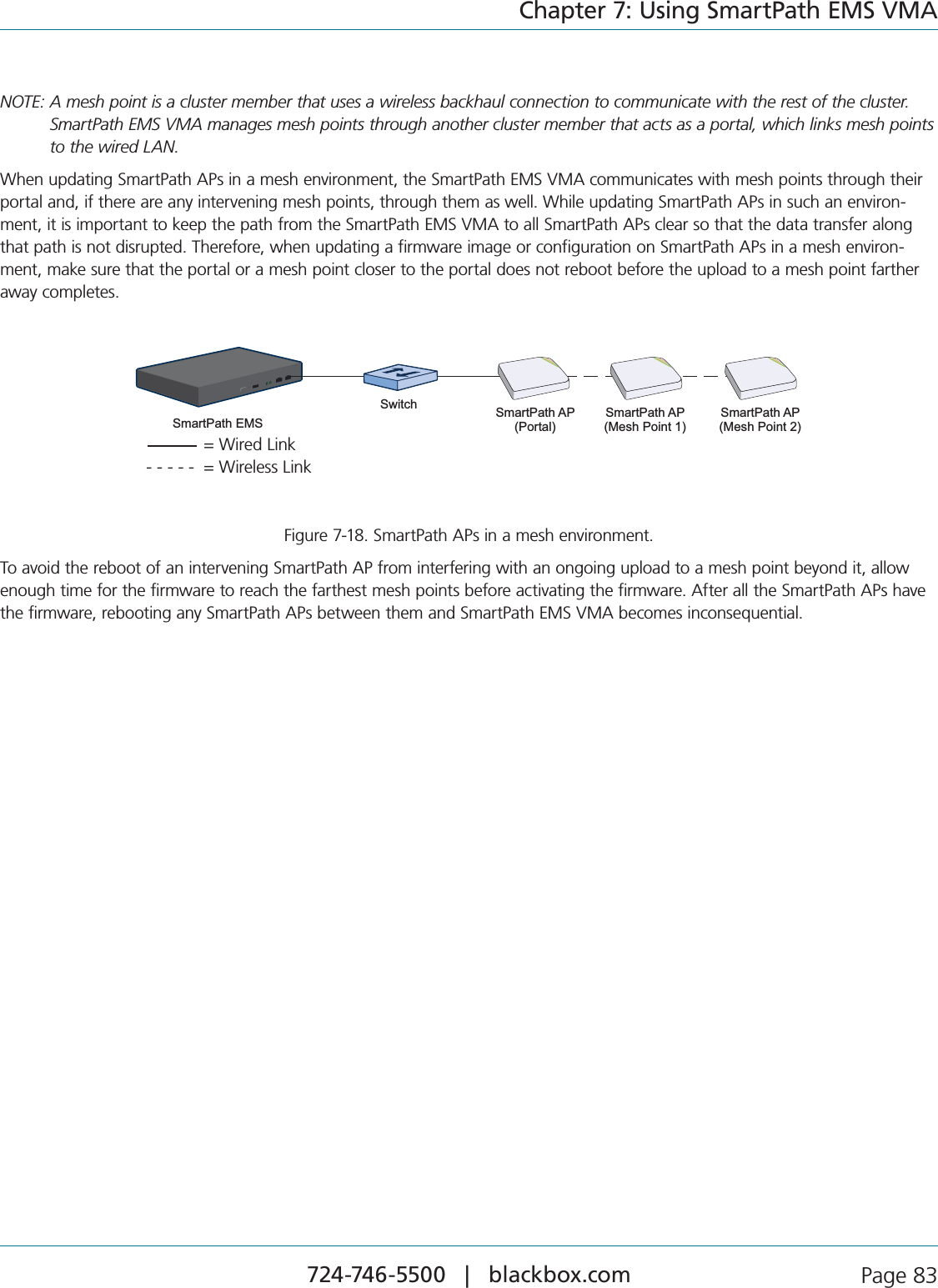
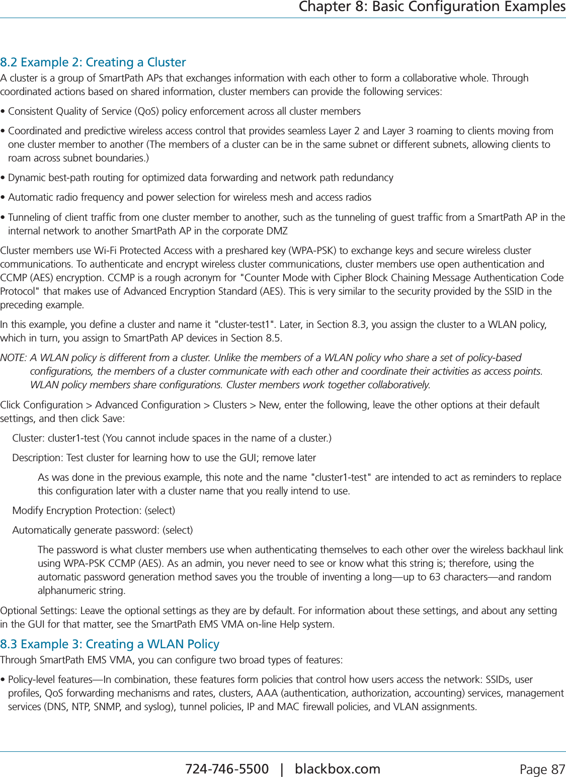
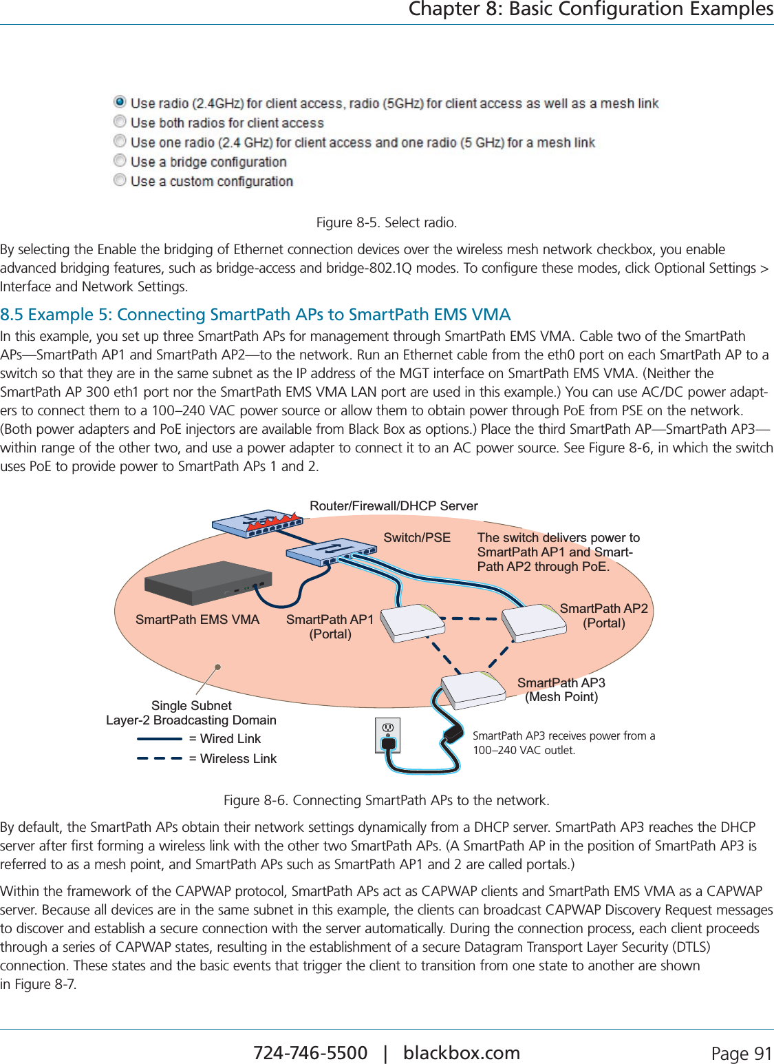
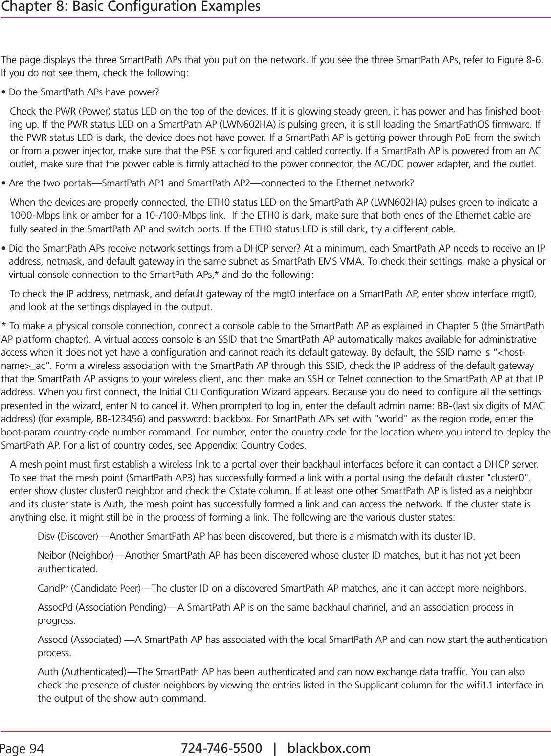
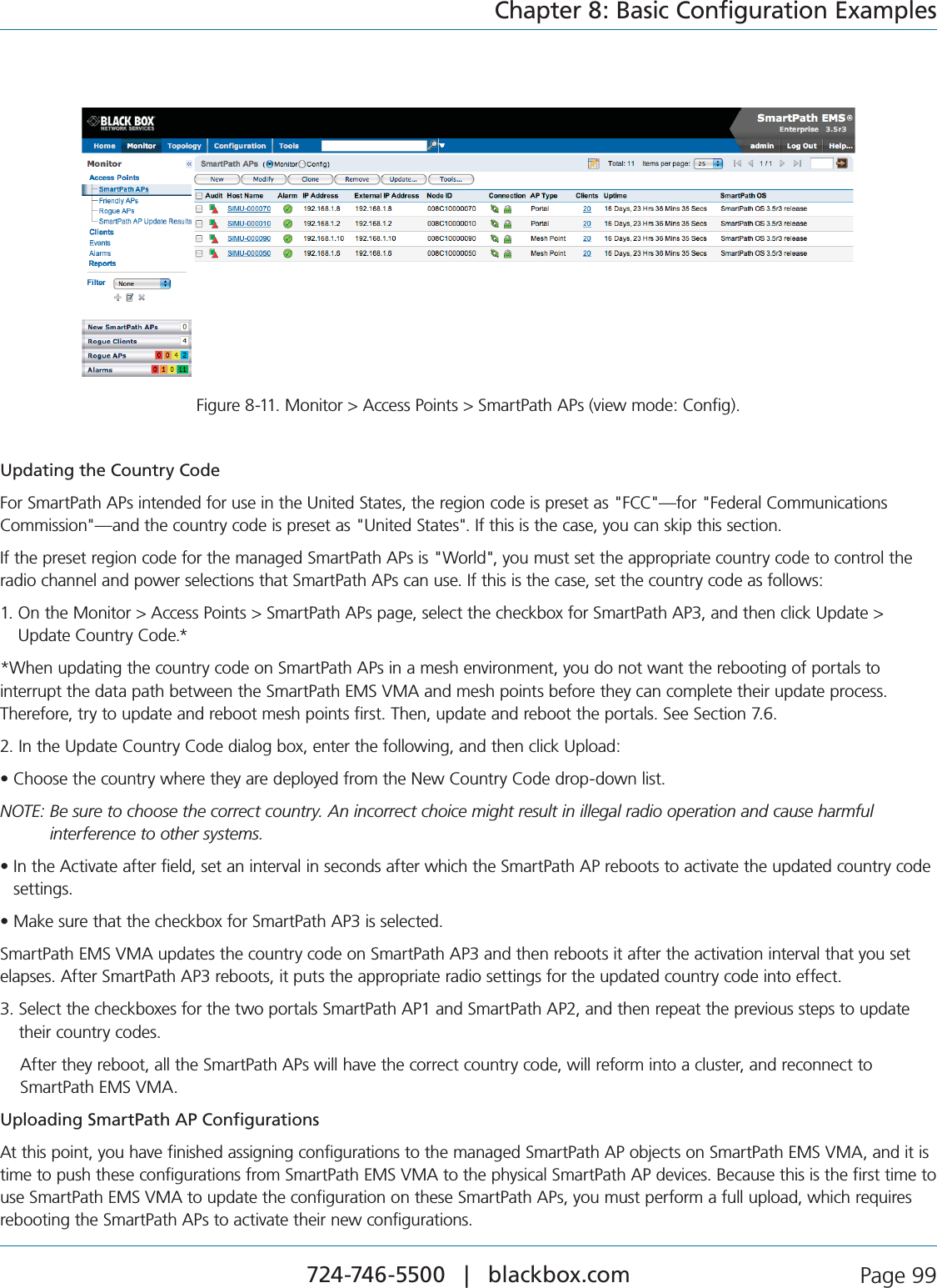
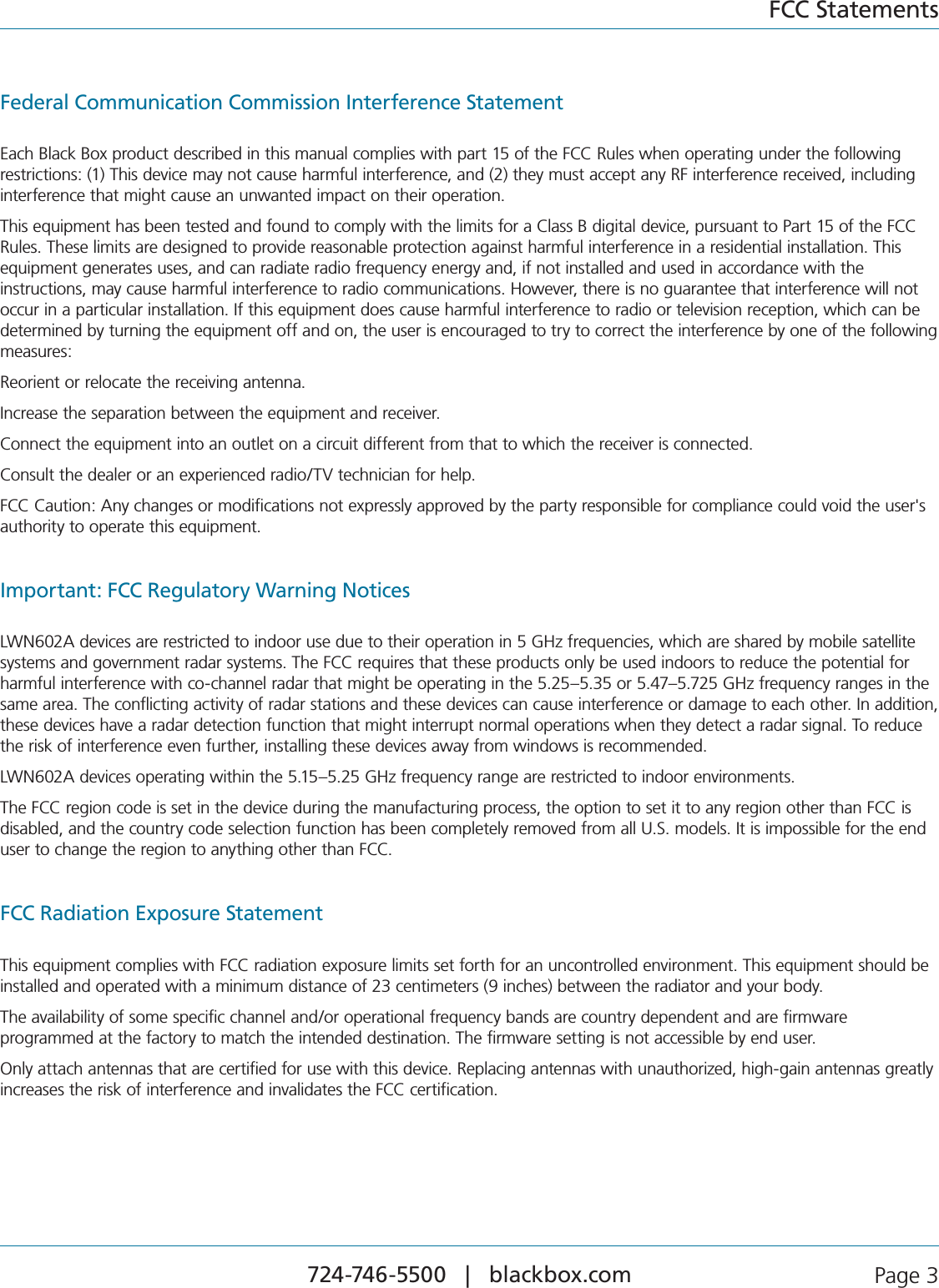
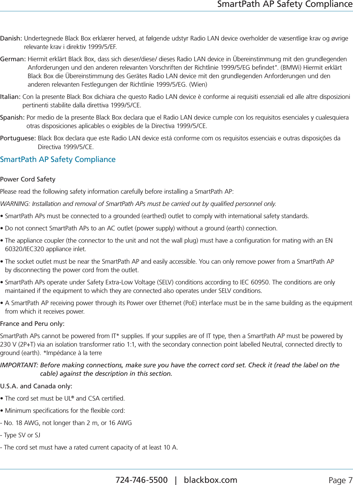
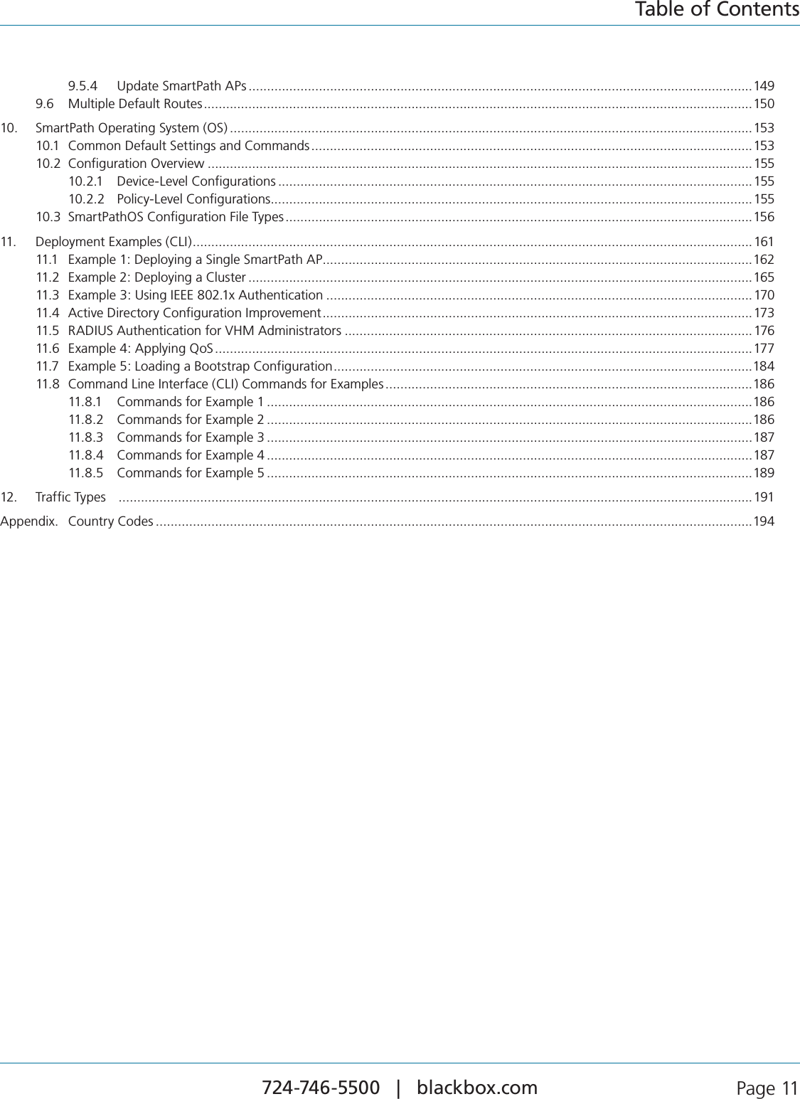
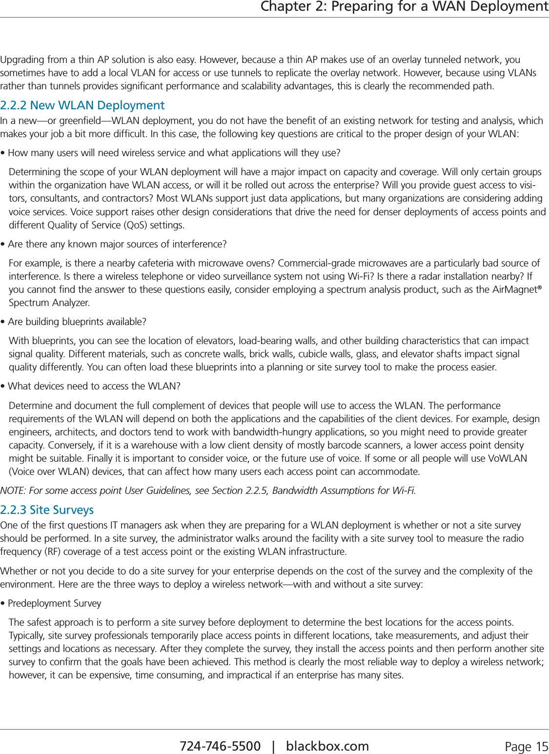
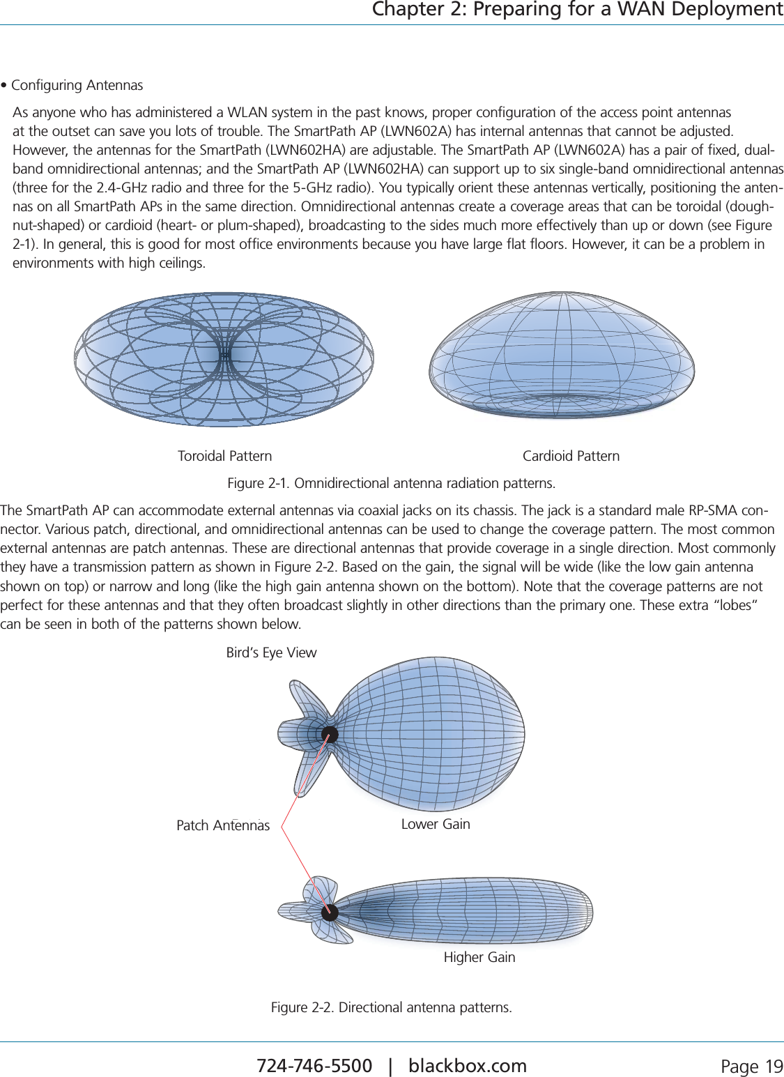
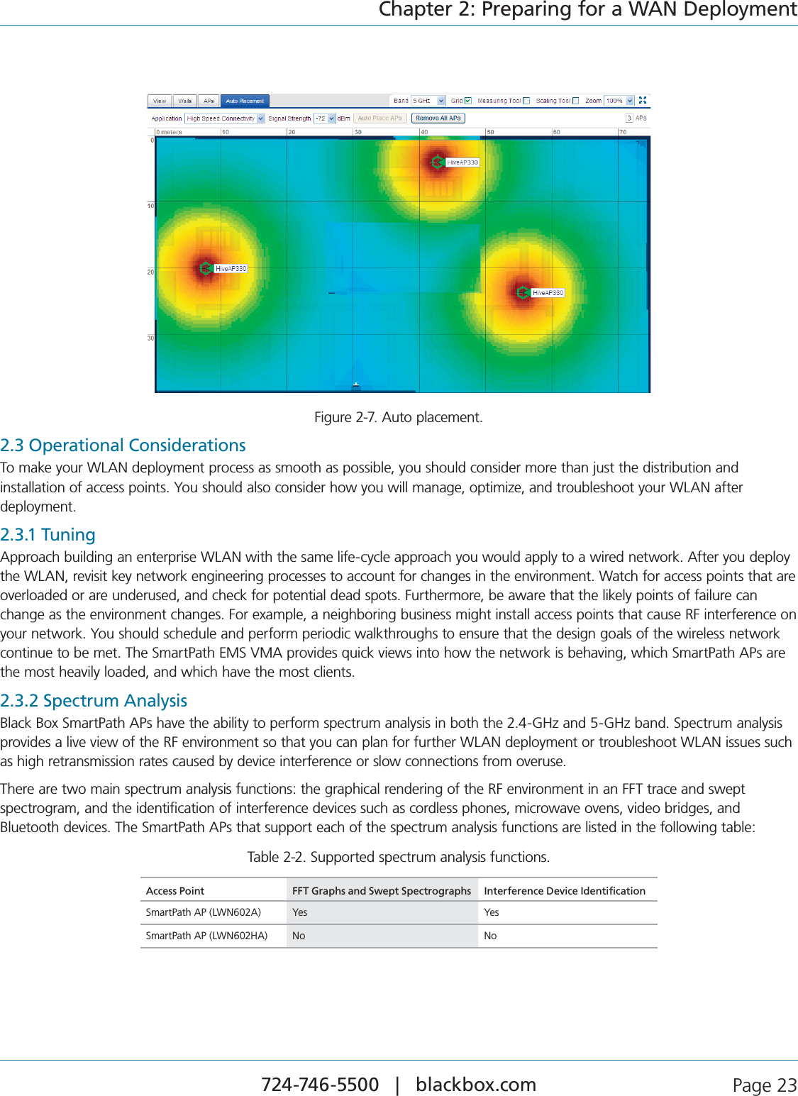
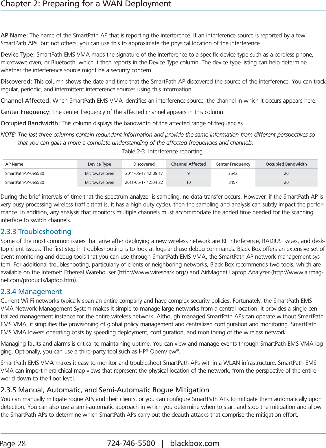
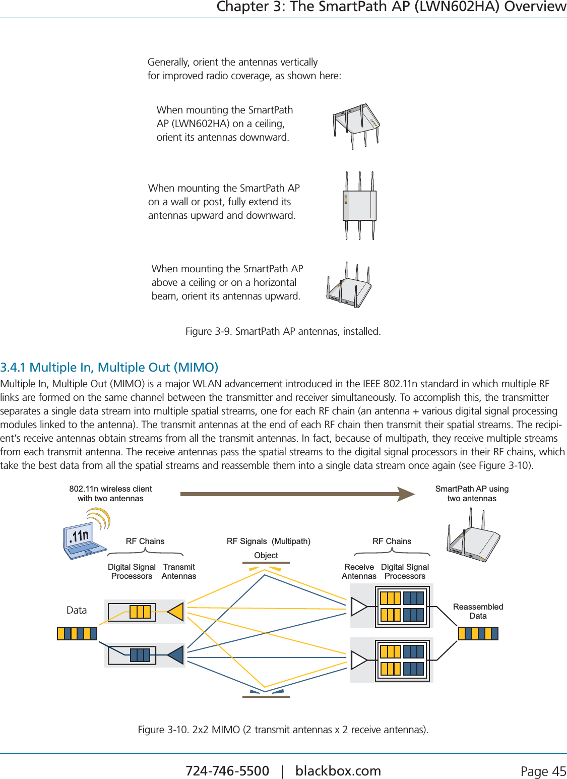
![724-746-5500 | blackbox.com Page 59Chapter 4: The SmartPath AP (LWN602A) Overviews9ELLOW4HEDEFAULTROUTEISTHROUGHABACKHAUL7I&IINTERFACEBUTNOTALLCONDITIONSFORNORMALOPERATIONSWHITEHAVEBEENmet.s7HITE4HEDEVICEISPOWEREDONANDTHEFIRMWAREISOPERATINGNORMALLYTHATISAWIRELESSINTERFACEINACCESSMODEISUP AWIREDORWIRELESSBACKHAULLINKISUPANDTHE3MART0ATH!0HASA#!07!0CONNECTIONTOEITHER3MART0ATH%-36-!ORA management AP.s0URPLE!NEWIMAGEISBEINGLOADEDFROM3MART0ATH%-36-!ORAMANAGEMENT!0s/RANGE!NALARMINDICATINGAFIRMWAREORHARDWAREISSUEHASOCCURREDFor locations where the status indicator might be a distraction or attract unwanted attention, you can adjust its brightness level FROMBRIGHTTHEDEFAULTTOSOFTTODIM9OUCANEVENTURNITOFFCOMPLETELY)N3MART0ATH%-36-!CHOOSETHEBRIGHTNESSLEVELthat you want from the LED Brightness drop-down list on the Configuration > Management Services > Management Options page. Through the CLI, enter [ no ] system led brightness { soft | dim | off }. The four settings are represented graphically in Figure 4-2.Bright Soft Dim OffBright Soft Dim OffFigure 4-2. Adjustable status indicator brightness levels.4.4 AntennasAntennas are an integral part of the SmartPath AP (LWN602A). The SmartPath AP LWN602A has four internal single-band ANTENNAS4WOOFTHEANTENNASOPERATEINTHE'(ZBAND)%%%BGNANDHAVEAD"IGAIN4HEOTHERTWOANTENNASOPERATEINTHE'(ZBAND)%%%ANANDHAVEAD"IGAIN!LLANTENNASAREOMNIDIRECTIONALPROVIDINGFAIRLYEQUALCOVER-age in all directions in a cardioid (heart-shaped) pattern around each antenna (see Figure 2-1).On the SmartPath AP LWN602A, the two 2.4-GHz antennas link to one radio, and the two 5-GHz antennas link to the other radio, both of which can operate concurrently. The relationship of antennas and radios is shown in Figure 4-3.Radio 1RF 802.11b/g/n2.4 GHzRadio 2RF 802.11a/n5 GHz5 GHzAntenna5 GHzAntenna2.4 GHzAntenna2.4 GHzAntenna5-GHz antenna2.4-GHz antenna2.4-GHz antenna5-GHz antennaFigure 4-3. Cut-away view of the SmartPath AP (LWN602A) showing the relationship of the internal antennas and radios.](https://usermanual.wiki/Black-Box/LWN602WA.User-Manual/User-Guide-1818882-Page-59.png)