BlackBerry R902M-2-O Wireless Data Modem User Manual RIM 902M Integrator s Guide
BlackBerry Limited Wireless Data Modem RIM 902M Integrator s Guide
Contents
- 1. User guide
- 2. Revised copy of Integrator Manual
User guide

,QWHJUDWRU·V
*XLGH
5,00
2(05DGLR0RGHP

RIM 902M OEM Radio Modem Integrator’s Guide
Last Updated: January 11, 1999
Model No. R902M-2-O
© 1999, RESEARCH IN MOTION LIMITED
Research In Motion and RIM are registered trademarks of Research In Motion Ltd.
Mobitex is a trademark of the Swedish Telecommunications Administration.
MS-DOS is a registered trademark, and Windows is a trademark, of Microsoft Corp.
Warning: This document is for the use of licensed users only. Any unauthorised
copying, distribution or disclosure of information is a violation of copyright laws.
While every effort has been made to ensure technical accuracy, information in this
document is subject to change without notice and does not represent a commitment on
the part of Research In Motion Limited.
Research In Motion
295 Phillip Street
Waterloo, Ontario
Canada N2L 3W8
tel. (519) 888-7465
fax (519) 888-7884
E-mail: rim902m@rim.net
Web site: www.rim.net
MOBITEX Interface, specified
in Specification
LZBA 703 1001,
compatible equipment

FCC Compliance Statement (USA)
FCC Class B Part 15
This device complies with Part 15 of FCC Rules. Operation is subject to
the following two conditions:
1. This device may not cause harmful interference, and
2. This device must accept any interference received, including
interference that may cause undesired operation.
Warning
Changes or modifications to this unit not expressly approved by the
party responsible for compliance could void the user’s authority to
operate this equipment.
This equipment has been tested and found to comply with the limits for a
Class B digital device, pursuant to Part 15 of the FCC Rules. These
limits are designed to provide reasonable protection against harmful
interference in a residential installation. This equipment generates, uses
and can radiate radio frequency energy and, if not installed and used in
accordance with the manufacture’s instructions, may cause harmful
interference to radio communications.
There is no guarantee, however, that interference will not occur in a
particular installation. If this equipment does cause harmful interference
to radio or television reception, which can be determined by turning the
equipment off and on, the user is encouraged to try to correct the
interference by one or more of the following measures:
Re-orient or relocate the receiving antenna.
Increase the separation between the equipment and receiver.
Connect the equipment into an outlet on a circuit different from
that to which the receiver is connected.
Consult the dealer or an experienced radio/TV technician for
help.

Industry Canada Certification
This device complies with Industry Canada RSS 119, under certification
number TBD.
IC Class B compliance
This device complies with the Class B limits for radio noise emissions as set
out in the interference-causing equipment standard entitled “Digital
Apparatus,” ICES-003 of Industry Canada.

Contents
FCC Compliance Statement (USA) ........................................i
Industry Canada Certification ...............................................ii
About this guide.................................................................... v
1. Introduction............................................................... 1
Radio performance...................................................................... 1
Mobitex network technology....................................................... 4
FCC radio frequency exposure rules............................................ 5
2. Getting started........................................................... 9
Test board overview...................................................................10
How to connect the test board.....................................................11
The MENU diagnostics tool.......................................................12
3. Mechanical integration ........................................... 21
Environmental properties...........................................................21
Physical properties.....................................................................22
Mounting methods.....................................................................24
Cables and connectors................................................................27
4. Power requirements ................................................ 31
Load specifications ....................................................................31
Batteries ....................................................................................32
Plug-in supplies .........................................................................34
Automotive supplies...................................................................34
5. Interface specification............................................. 35
MASC and RAP link-layer protocols .........................................35
Pin descriptions .........................................................................37
How to turn the radio on and off ................................................42
Interface to an RS-232 device.....................................................43
Interface to microprocessor ........................................................43
6. Antenna selection .................................................... 45
Selecting an antenna..................................................................45

Introduction to antenna terminology ..........................................46
Positioning the antenna..............................................................49
Shielding ...................................................................................50
Specifications ...................................................................... 51
Glossary of terms ................................................................ 53
Index.................................................................................... 55

About this guide
This document is a guide to integrating the RIM 902M OEM radio modem into
a variety of devices such as laptop computers, handhelds, vending machines,
point-of-sale terminals, vehicle-based mobile terminals, and alarm system.
Topics covered in this guide include:
mounting requirements
power (battery) characteristics
interfacing to the RIM 902M
antenna selection and placement
Throughout the guide, there are suggestions and precautions that will ease the
implementation of a wireless communication solution. These recommendations
are based on years of experience integrating wireless modems into a variety of
devices. You are welcome and encouraged to contact RIM if you would like to
discuss the technical implementation of this radio modem.


1. Introduction
With the introduction of the RIM 902M, Research In Motion (RIM) has set a
new standard for radio modem performance. The RIM 902M is unrivaled in the
key areas of receiver sensitivity, ouput efficiency, noise immunity, and power
consumption. Its small size and weight make it suitable for virtually any
wireless data application, including handheld devices and mobile terminals.
The RIM 902M is designed for use with Mobitex wide-area wireless data
networks operating in the 900 MHz range, such as the BellSouth Intelligent
Wireless Network.
RIM radio modems are specifically designed to integrate easily into a computer
or other embedded system. Potential applications include:
Laptop computers Vehicle tracking and location
Point of sale devices Monitoring and telemetry
Ruggedized terminals Vending machines
Handheld PC’s Utility meters
Parking meters Billboards
Dispatching Security alarm panels
Radio performance
The RIM 902M offers the highest performance of any radio modem for
Mobitex wireless data networks:

2 Introduction – Radio performance
Integrator’s Guide – RIM 902M OEM Radio Modem
Receiver sensitivity
Receiver sensitivity is a measure of how well a radio modem can “hear” a
network base station. This figure is important when a device will be used in
areas where signal strength is weak, such as inside buildings and in locations
that are not close to a base station. A radio modem with good receiver
sensitivity can be used in more places than a radio modem with poor sensitivity.
The RIM 902M has a receiver sensitivity of –118 dBm, or 0.0016 picowatts.
This is the strength of the weakest digital signal that can be interpreted with a
1% bit error rate. Although 1% may seem high, the sophisticated over-the-air
Mobitex protocol corrects these errors before the data is passed to the
application, ensuring error-free communication. This capability is already built
into the radio’s firmware, and does not require any additional software
development.
Noise immunity
The RIM 902M is not de-sensitized by the electromagnetic interference (EMI)
or “noise” that is generated by the electronics of the terminal into which it is
integrated. As a result, no special shielding is required between the radio and
your device.
Noise immunity offers several benefits, including:
easier integration improved RF performance
longer battery life more coverage from each base station
increased reliability no need for special RF shielding
Powerful and efficient transmitter
When necessary, the RIM 902M can supply a full 2.0 watts to the antenna.
However, the RIM 902M quickly decreases the output power when it is close to
a base station to as little as 0.06 watt – because a stronger signal is needed
only when far from a base station. By transmitting a strong signal only when
necessary, the RIM 902M conserves battery power.
The RIM 902M provides reliable transmit efficiency across the entire operating
voltage range of 4.15 to 4.75 volts. As a result, batteries can be used even when
nearing depletion. This also maximizes the radio coverage area throughout the
life of the battery.

Introduction – Radio performance 3
RIM 902M OEM Radio Modem – Integrator’s Guide
Low power requirements
If you are planning to integrate the RIM 902M into a handheld or portable
device, battery life is a critical issue: your customers will insist on long lasting
devices without heavy battery packs. The RIM 902M sets a new power
consumption standard for Mobitex radio modems. This ensures efficiency and
maximizes battery life.
Transmitting data: 1.7 amps or less (at 4.5V), depending on output power
The transmitter is ON for a pulse of between 32 ms and 1 second per
packet, depending on the amount of data transmitted. The maximum
packet size for a Mobitex device is 512 bytes.
Receiving data: 60 mA (at 4.5V)
The radio turns its receiver ON for a 150 ms “window” once every 10
seconds. The base station will only attempt to communicate with the radio
during this window. To minimize latency during rapid two-way
communication, the receiver is also turned ON and kept ON for 10
seconds after any communication (transmit or receive) with the network.
Standby power: 0.3 mA (at 4.5V)
Standby power consumption is very low and occurs when no radio activity
has taken place for at least 10 seconds. The radio and base station are
closely synchronized to ensure that a communication attempt is not missed
when the radio is in standby mode.
Battery life is not a concern for certain applications, such as in-vehicle
applications that draw power from the vehicle battery. For these applications, it
is possible to put the radio in an express operating mode, in which power
consumption is higher than normal but packet transfer latency is reduced to a
minimum.
Small size
Using a single board design, the RIM 902M is very thin, and much smaller
than a business card, at only 42.0 by 67.5 mm. This tiny size allows the
RIM 902M to meet tight space requirements within most applications. The fact
that a single board is used means that the device is much more reliable than
multi-board designs, particularly in high-vibration environments such as
vehicles.

4 Introduction – Mobitex network technology
Integrator’s Guide – RIM 902M OEM Radio Modem
Mobitex network technology
The Mobitex wireless network technology, developed by Eritel in 1984 for
Swedish Telecom, has become an international data communication standard.
Now managed by the Mobitex Operators Association (MOA), which controls
the specifications for this open standard, Mobitex is a secure, reliable, wireless
packet switching network specifically designed for wide-area wireless data
communications.
Mobitex networks are deployed around the world. The technology is presently
available in the following countries:
Australia Germany Singapore
Austria Indonesia Sweden
Belgium Italy Turkey
Canada Korea United Kingdom
Chile Netherlands United States
Finland Norway Venezuela
France Poland
Mobitex networks in the United States, Canada, Korea, Chile, and Venezuela
operate in the 900 MHz range, and are therefore directly compatible with the
RIM 902M OEM radio modem. Currently, Mobitex networks in other countries
operate at other frequencies, such as 400 MHz.
Mobitex provides highly reliable, two-way digital data transmission. The
network provides error detection and correction to ensure the integrity of the
data being sent and received, and includes transmission acknowledgment.
The Mobitex network has a hierarchical structure that allows messages to be
routed from sender to receiver along the most direct path possible. Each radio
cell is served by an intelligent base station. Because intelligence is distributed
throughout the network, data is only forwarded to the lowest network node
common to the sender and the receiver. For example, one base station is able to
handle all traffic in its coverage area.
The network constantly monitors the location of the mobile users. As a mobile
moves from one area of coverage to another, base stations track its signals,
sending updated mobile location and status information to the network. If the
network goes down at any point in transmission, the message is held until
network service is restored. If the mobile receiver moves outside the coverage
area, the base station stores the data until coverage is re-established, then

Introduction – FCC radio frequency exposure rules 5
RIM 902M OEM Radio Modem – Integrator’s Guide
forwards it to the mobile. This prevents data loss, and increases the reliability
of transmission.
Mobitex is optimized for data communication. It uses a packet switching
technique to provide the greatest flexibility in data transmission. Conventional
cellular phone systems, by contrast, use a circuit-switched network, in which a
physical connection is created between the sending and receiving nodes, and
must be maintained throughout the duration of the transmission. With circuit-
switched systems, the set-up time for establishing a connection involves
significant overhead and airtime cost, especially when only a small amount of
data needs to be transferred.
Mobitex packets include information about the origin, destination, size, type,
and sequence of data to be sent. This enables packets to be transmitted
individually, in any order, as traffic permits. Internal to the network, individual
packets may travel along different routes, in any order, without interfering with
other packets sent over the same frequency by different users. At the receiving
end, all packets are accounted for, and reassembled into the original message.
Set up time is eliminated and network connection is instantaneous. As a result,
packet-switching makes far more efficient use of channel capacity, typically
allowing 10 to 50 times more users over a radio channel than a circuit switched
network.
FCC radio frequency exposure rules
Based on FCC rules 2.1091 and 2.1093(1) and FCC Guidelines for Human
Exposure to Radio Frequency Electromagnetic Fields, OET Bulletin 65 and its
Supplement C(2), all integrations of the RIM 902M OEM unit are subject to
routine environmental evaluation for RF exposure prior to equipment
authorization or use.
For portable devices, defined in accordance with FCC rules as a transmitting
device designed to be used within 20 cm of the user body under normal
operating conditions, RF evaluation must be based on Specific Absorption Rate
(SAR) limits in Watts/kg. SAR is a measurement of the rate of energy
absorption per unit mass of body tissue.
For mobile devices, defined as a transmitting device designed to be generally
used such that a separation distance of at least 20 cm is maintained between the

6 Introduction – FCC radio frequency exposure rules
Integrator’s Guide – RIM 902M OEM Radio Modem
body of the user and the transmitting radiated structure, the human exposure to
RF radiation can be evaluated in terms of Maximum Permissible Exposure
(MPE) limits for field strength or power density in mWatts/cm2.
RIM will submit module specific information and test reports for a generic
MPE compliance. For an end product not covered by RIM testing and
submission, the integrator will submit for a separate FCC ID. The submission
should include end product information, end product SAR/MPE test report and
a reference to RIM module FCC ID for all other Part 90 requirements.
SAR and MPE limits
SAR limits for General Population/Uncontrolled exposure is 1.6 W/kg for
partial body exposure, averaged over 1 g of tissue and 4 W/kg for hands, wrists
and feet averaged over 10 g of tissue. The limits for Occupational/Controlled
exposure are more relaxed, i.e., 8 W/kg for partial body and 20 W/kg for hands,
wrists and feet. The 1.6 W/kg limit applies for most of RIM OEM integrators.
The limit for MPE is 0.6 mW/cm2 at 900 MHz.
Guidelines
RF exposure distance is based on normal operating proximity to the user’s
body. This distance is measured from the feed point of the antenna to the
closest body part. A test need to be performed to determine the passing distance
that meets the exposure limits.
Operating manual compliance statement
The integrator should include a statement in their operation/user/installation
manual making the user aware of RF exposure issues and insuring that the
users keep a passing distance from the antenna while transmitting.
Also the integrator should provide instructions or diagrams in the manual for
proper antenna mounting and position, when applicable, to ensure a safe
exposure distance to the operator and nearby persons.

Introduction – FCC radio frequency exposure rules 7
RIM 902M OEM Radio Modem – Integrator’s Guide
Label
If the final device configuration cannot be controlled so as to limit the user
distance to the antenna then the device needs to have an RF radiation hazard
label warning the user to keep away from the antenna by the specified distance.


2. Getting started
RIM is committed to facilitating the integration of the RIM 902M OEM radio
modem. We provide the necessary resources to evaluate the feasibility of
implementing a wireless communication solution, and work closely with our
partners to develop an application in the shortest time possible.
Years of intense R&D have spawned several tools that have been used
internally to help streamline our own development process. We have included
many of these tools with the RIM 902M OEM Developer’s Kit. The purpose of
the Kit is to accelerate radio integration and to help system designers evaluate
the RIM 902M. Using the Kit, you can quickly begin interfacing the radio
modem to your computing device.
We’re here for you!
RIM has a team of experienced engineers who can support you in the design
and implementation of your project. If you need help getting started, or if you
have any questions about the radio technology or its integration into your
platform, please contact the RIM 902M engineering development team:
e-mail: rim902m@rim.net
phone: +1 (519) 888-7465
fax: +1 (519) 888-7884
web: www.rim.net

10 Getting started – Test board overview
Integrator’s Guide – RIM 902M OEM Radio Modem
Test board overview
The RIM test board provides a standard RS-232 serial interface between a PC
and the radio modem. It is designed to help you quickly interface the
RIM 902M to a standard PC (through a COM port) or a terminal device with
an RS-232 serial port. The test board also provides access points to the radio’s
serial communication port, which allows you to monitor activity with a logic
probe, multimeter, or oscilloscope.
The test board includes the following components and functionality:
RS-232 interface
The serial (COM) port on a PC and most terminal devices operates at RS-232
signal levels, which are typically 12V. This high voltage would damage the
RIM 902M, which is typically integrated into a device that operates an
asynchronous serial port at 3.0V. The RS-232 interface on the test board allows
you to produce an output from the radio that is easily interpreted by a PC.
Test points
The test board is more than just an RS-232 interface. It also features debugging
facilities to help you test your application. It provides direct access to each of
the 22 pins on the serial data cable, which allows connectivity to analytical
equipment (e.g. logic probe, multimeter, or oscilloscope) and real-time
indication of data flow.
On/off switch
With the switch in the ON position, the radio will turn on whenever power is
applied to the test board. When the switch is moved to the OFF position, the
radio will shut down.
Power supply
The RIM 902M must be provided with a clean, high-current power source. In
this case, we use a standard plug-pack to provide the current necessary to

Getting started – How to connect the test board 11
RIM 902M OEM Radio Modem – Integrator’s Guide
operate the radio. The voltage is converted into the necessary levels by the
power supply section on the test board.
LED indicators
The test board includes several LED indicators designed to indicate the flow of
data to and from the host (in real time), the radio power status, power to the test
board, and more.
How to connect the test board
Now that you are familiar with the components and functions of the test board,
you are ready to connect the RIM 902M radio modem to an antenna and to a
PC (or some other computing device with an RS-232 serial interface). To do
this, you will use the test board and cables supplied with your RIM 902M
Developer’s Kit.
1. Flat serial cable (test board to radio)
The flat serial interface cable carries data between the test board and the
RIM 902M. Control and status signals such as TURNON are also carried on
this cable. Use this cable to connect the RIM 902M’s serial connector to the test
board.
This cable also carries clean, regulated power to the RIM 902M.
When inserting the cable, ensure that the side with the bare pins are in direct
contact with the pin side of the connector.
2. DB-9 serial cable (test board to PC)
Connect the male end of the straight-through DB-9 serial cable to the test
board.
Connect the female end of the cable to your PC’s COM port.

12 Getting started – The MENU diagnostics tool
Integrator’s Guide – RIM 902M OEM Radio Modem
3. Power adapter (test board to AC outlet)
Plug the 120VAC-to-12VDC power adapter into the wall outlet. Connect the
other end to the power jack of the test board.
4. Antenna cable (radio to magmount antenna)
Your developer’s kit includes a high-performance, 6dB-gain magmount
antenna. This antenna is terminated with a screw-on SMA plug. The
RIM 902M radio modem includes a snap-on MMCX jack. The antenna cable
supplied with your developer’s kit connects the antenna’s SMA plug to the
radio’s MMCX jack.
The magmount antenna provides the best RF performance when placed on a
broad metal surface, such as the roof of a car. When used inside a building,
performance is improved if the antenna is located near a window, with few
obstacles (wall, furniture, equipment, etc.) between the antenna and the
window. The antenna performs equally well if it is positioned upside down.
5. Turn the system on
The power switch on the test board is connected to the TURNON line of the
RIM 902M radio modem. To determine whether the radio is on, look at the
LED marked ONI. It is lit when the radio is on.
The MENU diagnostics tool
Now that you have successfully connected your RIM 902M radio modem to
your PC, you are ready to send a test packet through the Mobitex network.
Your radio modem should be activated by the network operator in order to be
used on the Mobitex network and to establish an airtime agreement. If you have
not already arranged for activation of your radio, contact your network
operator.

Getting started – The MENU diagnostics tool 13
RIM 902M OEM Radio Modem – Integrator’s Guide
The RIM 902M contains a diagnostic utility called MENU. With this utility,
you can set the current network, “ping” your radio modem, or view radio and
network status values.
Setup
The following instructions assume that your RIM 902M is connected to a PC
running a terminal program, such as Windows HyperTerminal. The MENU
utility is based in the RIM 902M’s firmware, so HyperTerminal is the only
software required to use it.
The MENU utility’s user interface is a full-screen text mode interface, and uses
the ANSI cursor command set. Programs like HyperTerminal support the ANSI
codes by default. If you are using a different terminal program that does not
provide ANSI cursor control, the MENU utility will drop into a line-by-line
interface. The appearance of the line-by-line interface is not documented here,
but the commands it uses are the same as those described below.
Select the COM port which communicates with the RIM 902M and configure
for 9600 bps, and either 7E1 (7 bits, Even parity, 1 stop bit) or 8N1 (8 bits, No
parity, 1 stop bit). If you have set this up correctly, you will see bursts of
characters from the radio modem such as ^0010B 47E,0:5D. These character
bursts are normal; the represent a MASC B frame, which you can ignore for
now.
Type the word menu (all in lower case letters only) then press the ENTER key.
You can expect to see a full screen of information. If nothing happens, simply
re-enter menu until the radio modem responds. The word “menu” itself will
probably not appear on the screen as you type it in.
If you re-enter menu and nothing occurs, ensure that the radio is turned on and
connected to the PC, and that all cables are securely connected. Please contact
RIM for assistance if you are stuck at this point.
Once the utility has been started, the terminal program’s screen will look
similar to the following:

14 Getting started – The MENU diagnostics tool
Integrator’s Guide – RIM 902M OEM Radio Modem
RIM 902M Firmware Version 1.0.0
(c) 1999 Research In Motion Limited
Radio Setup Radio Serial Number = 031/11/066300
Command Key Description Networks Available:
----------- ----------- -------------------
Q Quit and reset the radio. 1. RMDUS (B433/B433)
2. CANTEL (C4D7/C4D7)
N Set the current network.
P Ping: Send a Status MPAK to yourself.
Your Choice ?
MAN=16231144 RSSI= 40% 24 dBuV Battery= 97% Network=RMDUS (B433/B433)
Contact=Yes Mode=PowerSave Live Tx=Enabled Active=Yes Group List=Born
UpFreq=02FF DoFreq=0F2F Base/Area=14/0A Status=0080
The screen displays the software version and build date, the radio modem’s
serial number, the list of available Mobitex radio networks, current radio
modem status indicators, the “ping” function, and other relevant information.
RSSI stands for Received Signal Strength Indicator. This is a measure of
network coverage. The higher the number, the better the coverage. The RSSI is
given both as a percentage and in dB V (decibel microvolts). To obtain the
RSSI in dBm (decibel milliwatts), subtract 113 from the dB V value. Note that
RSSI= 0% 0 dB V does not necessarily represent the complete absence of a
signal; in many cases, the radio is capable of communicating with the network
at signal strengths of 0 dB V or even less. Actual contact with the Mobitex
network would be indicated by the Contact field. The RSSI is updated every
ten seconds, or whenever you press D.
The Battery indicator shows the level of supplied voltage. The battery level is
updated once every thirty seconds, or whenever you press D.
Network tells you which network you are currently using. The example shows
RMDUS (BellSouth Wireless Data, formerly RAM Mobile Data, operates a
Mobitex network in the United States) and CANTEL (Cantel AT&T operates a
Mobitex network in Canada).
MAN stands for Mobitex Access Number, which is a unique number that
identifies each Mobitex radio modem. The MAN is used for addressing packets.
The screen will also display a Radio Serial Number, which is unique to each

Getting started – The MENU diagnostics tool 15
RIM 902M OEM Radio Modem – Integrator’s Guide
radio modem. This number is often referred to in other documents as ESN
(Electronic Serial Number) or MSN (Mobitex Serial Number).
Mode shows whether the radio is in powersave mode or express mode. The
default operating mode is powersave, which reduces power consumption by the
radio but introduces a latency of up to 10 seconds when receiving packets from
the network. This mode may be changed through software.
Tx is an indicator to let you know whether the radio’s transmitter is enabled or
disabled. The transmitter may be enabled or disabled through software, and is
normally enabled. The Mobitex base station may also instruct a radio to shut
down (also referred to as DIE) if it is an illegal device, or not registered, or
causing disruption to the Mobitex network. The word Live on the status line
indicates that the radio is not in a DIE state.
A radio modem receives a Group List when it is powered up and registers with
the network base station. Normally, you would see Group List=OK, which
indicates that the radio has successfully signed onto a base station. If you see
Group List=Born, then either your device is out of coverage, or it has not been
activated by your network operator. Note that it can take 30 seconds for a radio
to display Group List=OK.
UpFreq and DoFreq show the channels (in hexadecimal) that you are using to
transmit and receive, respectively. If you are interested in obtaining the exact
current transmit frequency, divide UpFreq by 80 and add to 890. This gives a
value in MHz. Add 39 MHz to obtain the receive channel. For example, if the
display reads “UpFreq=02FF DoFreq=0F2F” then convert hexadecimal 02FF to
decimal 767, divide by 80 and add to 890, and obtain 899.5875 MHz, which is
the transmit channel. Add 39 MHz (or repeat the calculation using DoFreq) to
determine that the receive channel at 938.5875 MHz.
Base/Area indicate which base station you are using. Every base station in the
network is assigned a unique Base/Area combination. Base stations in the same
geographic area often share an Area address. Contact your network operator if
you want to know the location of network base stations.
Status describes the current state of the radio. Other documentation may also
refer to the Status value as the radio’s internal fault bits. The following table
shows the interpretation of the Status bits. If the Status value displayed on your
screen does not correspond to any of the values below, then determine which
values add together in hexadecimal to give the Status value that you see. For
example, status value B403 would simultaneously describe states A000, 1000,
0400, 0001, and 0002, as described below.

16 Getting started – The MENU diagnostics tool
Integrator’s Guide – RIM 902M OEM Radio Modem
0000 The radio modem status is normal. There are no warnings.
0001 The RIM 902M has been out of coverage for a long time. No adequate base
station was found. Possible causes include lack of network coverage, wrong
network selected, or the battery level is too low.
0002 This is a new RIM 902M being used for the first time. No action is necessary.
0008 The radio modem has exhausted its internal memory. This should not happen
under ordinary use. Turning the radio modem off and back on will resolve this.
0020 The network has issued a DIE command to the radio modem, perhaps because
it is not registered on the network. No data can be sent to the network until a
LIVE command is issued by the network. Contact the network operator for
help.
0040 The modem’s transmitter has been disabled by your software, using either the
MASC “F M0” or RAP “Turn Transmitter Off” command. The transmitter can
be turned back on with the MASC “F M1” or RAP “Turn Transmitter On”
command, or by resetting the radio.
0080 The radio modem has not yet received a grouplist from the network. If this bit
remains set after the modem has been in network coverage for several minutes,
your radio modem is probably not activated. Contact the network operator to
activate your device.
0100 Another device may be using the same MAN number as your device on the
same base station. This should not happen under ordinary use. It may cause
duplicate, dropped, or mixed up packets. Contact the network operator to
determine whether two units have the same MAN number.
0800 The RIM 902M may be having a problem remembering its last base station. If
the problem persists, the unit should be returned for repair.
1000 The RIM 902M has received an unknown interrupt and might be having
problems receiving packets. If the problem persists, the unit should be returned
for repair.
2000 The RIM 902M has received an unknown interrupt. No action is necessary.
4000 The RIM 902M has been damaged and cannot be used until this problem is
corrected. The unit should be returned for repair.
How to change to a different network
The RIM 902M radio may be used on different Mobitex networks operating on
different channels in the 900 MHz range. Up to 16 network channel lists may
be programmed by RIM into each radio. If the network shown is not the correct
one, you can choose another from the list of networks available. Press N and
the MENU utility will present an additional prompt for selecting the network,
as shown below.

Getting started – The MENU diagnostics tool 17
RIM 902M OEM Radio Modem – Integrator’s Guide
RIM 902M Firmware Version 1.0.0 release
(c) 1999 Research In Motion Limited
Radio Setup Radio Serial Number = 031/11/066300
Command Key Description Networks Available:
----------- ----------- -------------------
Q Quit and reset the radio. 1. RMDUS (B433/B433)
2. CANTEL (C4D7/C4D7)
N Set the current network.
P Ping: Send a Status MPAK to yourself.
Your Choice ? Choose a network from the list (1..2) ?
MAN=16231144 RSSI= 30% 22 dBuV Battery= 97% Network=RMDUS (B433/B433)
Contact=Yes Mode=PowerSave Live Tx=Enabled Active=Yes Group List=Born
UpFreq=02FF DoFreq=0F2F Base/Area=14/0A Status=0080
Change network name
You may now enter a number corresponding to the desired network shown
under Networks Available. When you press Enter, the radio modem will switch
to the selected network, as shown below. If you do not enter a number, or if you
erase the number you have typed, then no change will occur when you press the
Enter key. Pressing the Esc key will cancel the network set-up command.
The screen below shows what would happen if you typed in 2 and then pressed
the Enter key. The values shown beside Network, UpFreq, DoFreq, and
Base/Area are different.

18 Getting started – The MENU diagnostics tool
Integrator’s Guide – RIM 902M OEM Radio Modem
RIM 902M Firmware Version 1.0.0
(c) 1999 Research In Motion Limited
Radio Setup Radio Serial Number = 031/11/066300
Command Key Description Networks Available:
----------- ----------- -------------------
Q Quit and reset the radio. 1. RMDUS (B433/B433)
2. CANTEL (C4D7/C4D7)
N Set the current network.
P Ping: Send a Status MPAK to yourself.
Your Choice ?
MAN=16231144 RSSI= 45% 25 dBuV Battery= 97% Network=CANTEL (C4D7/C4D7)
Contact=Yes Mode=Fallback Live Tx=Enabled Active=No Group List=Born
UpFreq=030D DoFreq=0F3D Base/Area=1B/09 Status=0080
Radio update was successful.
“Ping” the network: an end-to-end radio test
You can determine whether your radio modem is working on the network by
pressing P. When you “ping,” you send a message (MPAK – Mobitex data
packet) to yourself via the wireless network base station. The MENU utility will
display a message indicating that the MPAK was sent. A few seconds later, it
should also indicate that the MPAK was received. This confirms that your radio
modem is operational and active on the network.
If you get the message “Status MPAK cannot be sent – out of coverage”, then
you are not in an area that is covered by the Mobitex network. You can
determine whether you are in coverage by looking at Contact on the status
lines. If you are certain that you are in a coverage area, but are still not able to
communicate with the network, check the antenna to make sure it is connected
properly and is deployed properly. Signal quality can vary significantly within a
building. Try moving the antenna to a new location, perhaps near a window, to
see if you can get a signal.
If you get the message indicating that the Status MPAK was sent, but you did
not get one that it was received, then you are in coverage but your RIM 902M
radio modem has probably not been activated by your network operator, and the
network will not send the MPAK back to the radio. Contact the network
operator to activate your design.

Getting started – The MENU diagnostics tool 19
RIM 902M OEM Radio Modem – Integrator’s Guide
RIM 902M Firmware Version 1.0.0
(c) 1999 Research In Motion Limited
Radio Setup Radio Serial Number = 031/11/066383
Command Key Description Networks Available:
----------- ----------- -------------------
Q Quit and reset the radio. 1. RMDUS (B433/B433)
2. CANTEL (C4D7/C4D7)
N Set the current network.
P Ping: Send a Status MPAK to yourself.
Your Choice ?
MAN=16231227 RSSI= 11% 14 dBuV Battery=100% Network=RMDUS (B433/B433)
Contact=Yes Mode=PowerSave Live Tx=Enabled Active=Yes Group List=Born
UpFreq=02FF DoFreq=0F2F Base/Area=14/0A Status=0080
Received MPAK from 16231227 (to 16231227) Type=03(STATUS ) Traffic/Flags=00
If you are unable to communicate with the network, then contact the network
operator to make sure that your device is activated on the network. If the radio
has not been activated, then the network will not send the MPAK back to the
radio. Second, make sure that you are in network coverage. You can determine
whether you are in coverage by looking at Contact on the status lines. If it
shows Contact=NO, then you are not in an area that is covered by your Mobitex
network. You can also determine whether the antenna is connected properly
and is deployed properly. Signal quality in buildings can vary significantly over
short distances. Try moving the antenna to a new location, perhaps near a
window, to see if you can get a signal. If none of these remedies help, contact
RIM for assistance.
Exiting the utility
When you have finished using the utility, you should press Q to quit. This step
is important because it allows the radio to resume accepting commands from
other software. The screen will clear and you will be informed that the radio
has been reset. You can safely disconnect the radio and close your terminal
program once you have seen this message.


3. Mechanical
integration
This chapter provides information about the RIM 902M that will be useful in
determining the physical positioning of the radio modem within an application.
Environmental properties and testing, physical properties, mounting methods,
and connector information are presented.
Environmental properties
During environmental testing, RIM takes samples of its radio modems and
subjects them to a variety of harsh conditions. We measure over a hundred
digital RF calibration parameters, once before and once after each test. The
difference between these measurements precisely reveal any performance
degradation. Each unit in the sample is also inspected visually after testing.
This experience allows us to fine-tune our design and manufacturing process.
Environmental testing ensures that our products are able to withstand both
typical and extreme real-world conditions in which they will be used. RIM does
not sell units that have been subject to environmental testing.

22 Mechanical integration: Physical properties
Integrator’s Guide – RIM 902M OEM Radio Modem
Storage temperature
The RIM 902M OEM radio modem may be stored at a temperature from -40 C
to +85 C (-40 F to +185 F).
Operating temperature
The RIM 902M is designed to operate between -30 C to +70 C (-22 F to
+168 F).
The end user should be careful not to exceed the upper temperature limit of
+70 C, as performance degradation or damage to the power amplifier may
occur past this point, especially when packets are transmitted frequently.
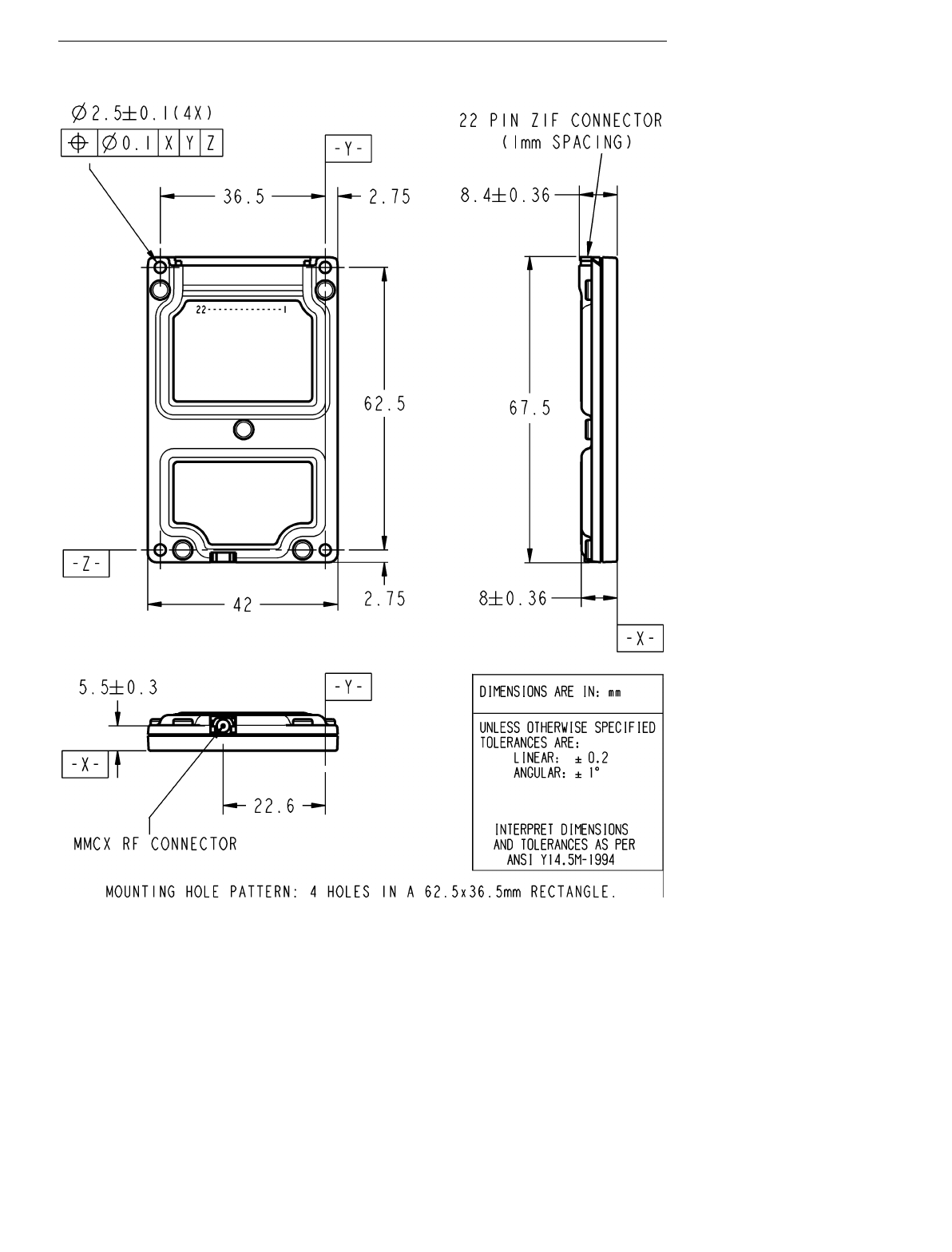
Physical properties
Weight
The RIM 902M weighs 1.2 oz (35 g), including the case.
Dimensions
The RIM 902M has been designed to meet the most stringent space
requirements. In most cases, there will be sufficient room in an existing
enclosure to house the radio modem.
The overall maximum dimensions of the radio modem, not including cables,
are:
Width: 42.0 mm
Length: 67.5 mm
Thickness: 8.4 mm
Mechanical integration: Physical properties 23
RIM 902M OEM Radio Modem – Integrator’s Guide

24 Mechanical integration: Mounting methods
Integrator’s Guide – RIM 902M OEM Radio Modem
Mounting methods
The RIM 902M OEM radio modem may be securely fastened using a variety of
methods. The operating environment must be carefully considered when
choosing a mounting option. For example, extreme temperature or heavy
vibration may require a special mounting solution. It is important to ensure that
the RIM 902M remains securely attached in the environment where it will be
used.
The following information is presented as a guide, but applications can vary
considerably. A mechanical engineer can help ensure that the mounting method
is suitable for the specific application.
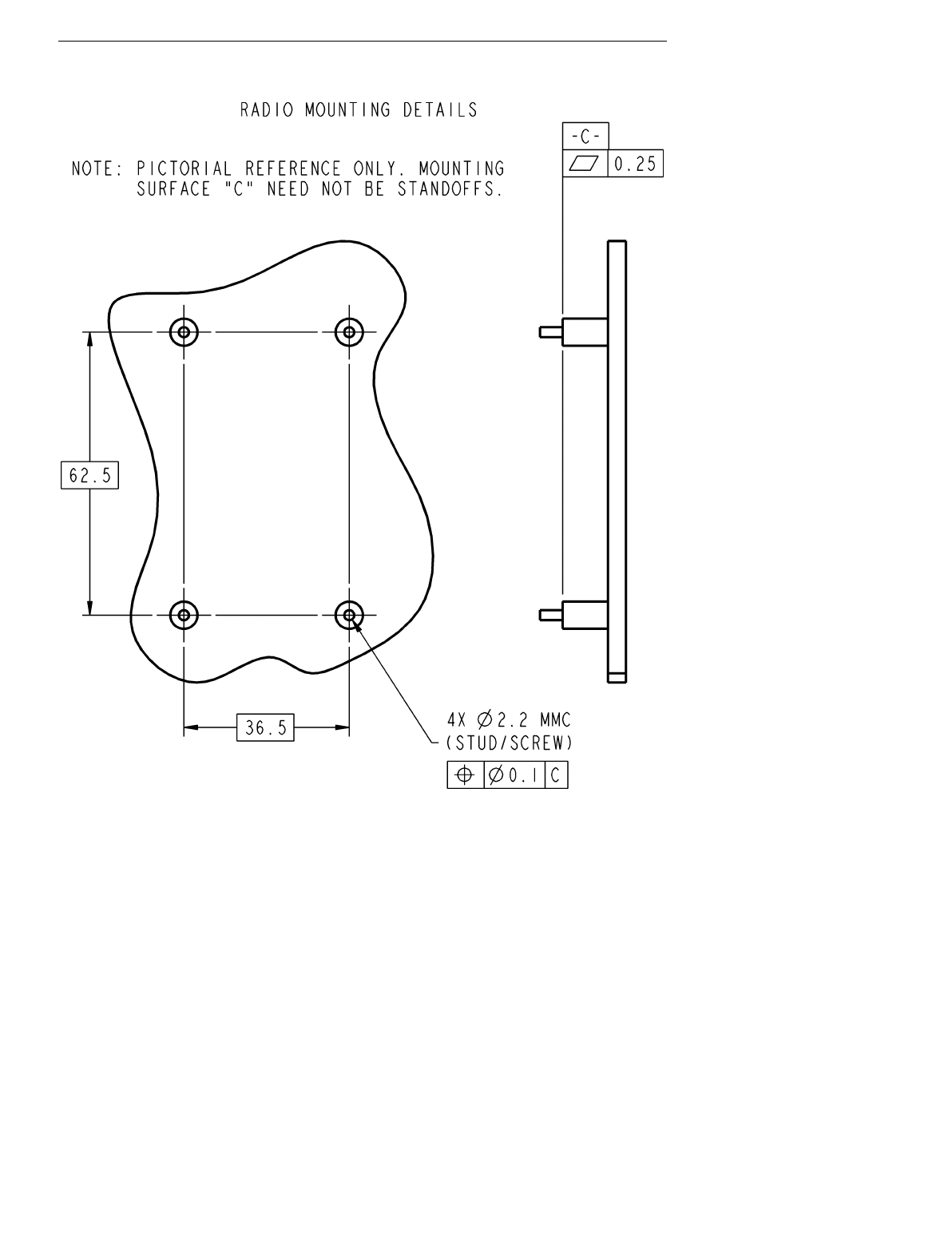
Bolts
The RIM 902M radio modem includes a hole in each corner, which may be
used to bolt the device onto a circuit board, device housing, or other surface.
The mounting hole pattern is four holes in a 62.5 by 36.5 mm rectangle, with
each hole 2.5 mm in diameter.
The following diagram illustrates the radio mounting details.
Mechanical integration: Mounting methods 25
RIM 902M OEM Radio Modem – Integrator’s Guide
Tie wraps
Tie wraps can be used to as a secure but non-permanent means of attaching the
RIM 902M to a surface. Typically, each tie wrap passes through a hole drilled

26 Mechanical integration: Mounting methods
Integrator’s Guide – RIM 902M OEM Radio Modem
into the surface on either side of the RIM 902M. This allows the radio to be
attached to a shell, a PCB, or some other mounting surface.
If using tie wraps, ensure that the surface beneath the RIM 902M is flat.
Otherwise, the mounting surface could push up on the bottom surface of the
radio case while tightening the tie wraps pushes down on the edge of the radio
case. This could cause the metal case of the RIM 902M to flex upward and
short across components inside the radio, causing the radio to malfunction. For
example, thick adhesive foam tape and tie wraps should not be used together.
Permanent industrial adhesive
The RIM 902M is small and lightweight enough to be attached to the host
device using an industrial adhesive. For some applications, this method of
mounting is preferable to bolts, because adhesive is easier to use in a
manufacturing environment, and is more resistant than bolts to loosening. In
many cases, an effective solution is to adhere the radio modem to the inside
surface of your product’s casing.
An adhesive should be chosen on the basis of its ability to stick to the material
used in the outer casing of the radio modem and in the surface to which the
radio will be mounted. The bottom casing of the RIM 902M is magnesium.
3M manufactures VHB, a permanent industrial adhesive with excellent long-
term holding power. The peel adhesion and tensile holding power of VHB tapes
are extremely high, making this a suitable solution when the radio will not
need to be removed. Choose foam tape for rough surfaces and adhesive tape for
smooth surfaces.
More information about VHB may be obtained by contacting 3M Industrial
Tape and Specialties Division at 1-800-227-5085 (fax: 1-612-733-1771). The
publication number for the VHB technical data sheet is 70-0702-0266-
1(104.5)R1.
Mechanical integration: Cables and connectors 27
RIM 902M OEM Radio Modem – Integrator’s Guide
Cables and connectors
There are two connectors on the RIM 902M radio modem. These connectors
allow interfacing from the radio modem to a serial computing device, a power
supply, and an antenna.
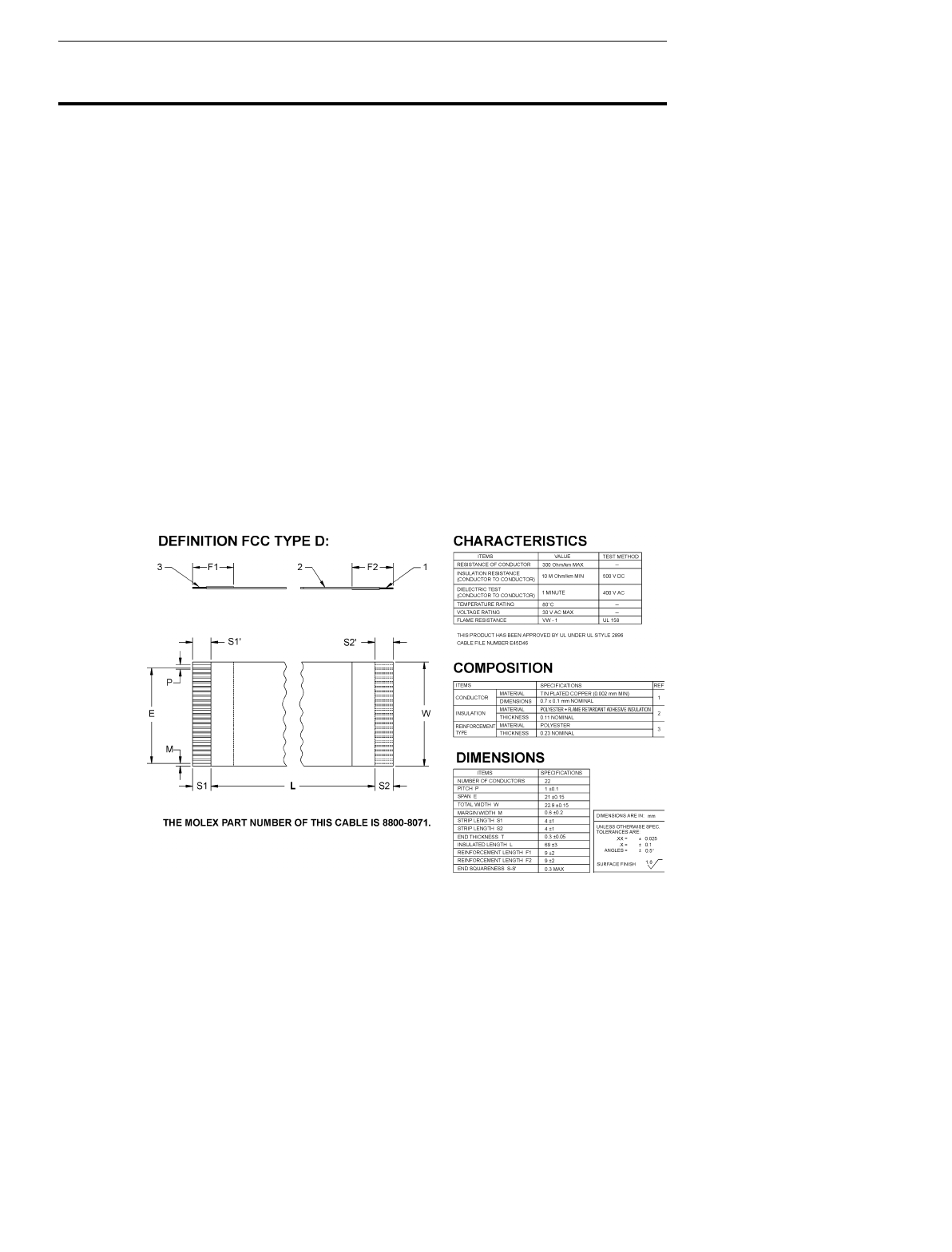
Serial cable and connector
The RIM 902M serial communication and control signals are carried on a flat
22-conductor 0.30 mm (0.012”) thick flexible printed circuit (FPC) cable in
1.00 mm centerline spacing, which can plug into a matching connector. Since
each application is unique, Molex can create a custom Flat Flex Cable Jumper
in the correct length and the correct connector orientation for your application.
The minimum cable length available is 30 mm (1.181”).
The serial cable supplied with the RIM 902M Developer’s Kit is a Type D 4”
long Flat Flex Cable Jumper in 1.00 mm centerline spacing, as illustrated in
the following mechanical drawing:

28 Mechanical integration: Cables and connectors
Integrator’s Guide – RIM 902M OEM Radio Modem
This cable can plug into a matching 22-position 1.0 [0.039] horizontal FPC
connector. A variety of connectors are manufactured by Molex. More
information about each connector, including mechanical drawings, is available
from the manufacturer’s web site (www.molex.com), or you can contact RIM
(rim902m@rim.net) for help with selecting an appropriate connector for your
application.
Contact:
Molex Headquarters Molex Electronics Ltd.
Lisle, IL, USA Toronto, Ontario, Canada
tel: (630) 969-4550 tel: (416) 292-1444
fax: (630) 969-1352 fax: (416) 292-2922
www.molex.com
Antenna cable and connectors
RIM selected the industry-standard MMCX connector for the RIM 902M
because it is a very small connector that has the mating force to withstand
heavy vibration.
Typically, an antenna does not plug directly into a RIM 902M. Instead, an
connector at the outer casing of the device. This allows the antenna to be
removed from the system without having to open the device, and it eliminates a
source of strain on the radio’s MMCX connector.
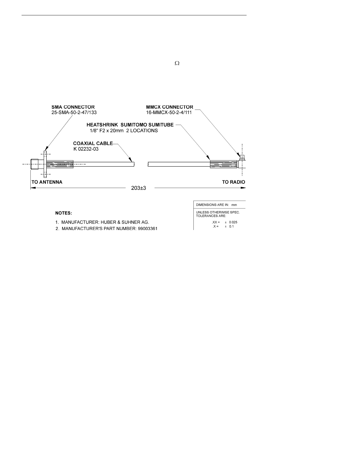
The antenna cable should have low loss, an impedance of 50 , and an MMCX
jack that mates with the RIM 902M’s MMCX plug. The other end of the cable
can be any connector you choose, as long as it has an impedance of 50 . An
SMA screw-on connector is suitable and widely available. TNC connectors are
also suitable, but larger than SMA. The antenna cable supplied with the
RIM 902M developer’s kit has an MMCX connector on one end and an SMA
connector on the other. The cable is built with strain reliefs to prevent damage.
Huber & Suhner can provide antenna cables and connectors. The parts
described below have an impedance of 50 and are suitable for use with the
RIM 902M.
Mechanical integration: Cables and connectors 29
RIM 902M OEM Radio Modem – Integrator’s Guide
11MMCX-50-2-1C/111 Straight MMCX connector
16MMCX-50-2-1C/111 Right-angle MMCX connector
25SMA-50-2-25/111 SMA connector
EZ Flex 405 Low-loss matching (50 ) cable
133REEZ4-12-S2/1216 8” cable, straight MMCX to SMA
133REEZ4-12-S2/1699 8” cable, right-angle MMCX to SMA
The following cable is included with the RIM 902M Developer’s Kit:
Contact:
Huber & Suhner Huber & Suhner
Essex Junction, VT, USA Kanata, Ontario, Canada
tel: (802) 878-0555 tel: (800) 627-2212
fax: (802) 878-9880 fax: (613) 596-3001
www.hubersuhnerinc.com


4. Power requirements
The RIM 902M radio modem must be provided with a clean power source
capable of delivering bursts of high current. This can be provided by a plug-in
power supply unit, a rechargeable battery pack, or single use batteries. RIM has
conducted extensive research and has developed guidelines for integrators to
follow when designing the power supply system for the RIM 902M.
Load specifications
The RIM 902M draws its power in bursts; the power required changes rapidly
depending on whether the radio is transmitting, receiving, or in standby. The
load profile is given on the following page. These specifications can be given
directly to your power supply designer or battery supplier.
Power supply parameters
The RIM 902M requires a clean, stable 4.15 to 4.75 volt source that is capable
of delivering a one-second burst of up to 1.7A when required by the transmitter.
Under non-ideal conditions such as an improperly matched antenna, however,
this burst could be as high as 2.2A. The receiver current consumption is 66 mA
and the standby current consumption is 0.07 to 0.2 mA. The maximum no-load

32 Power requirements: Batteries
Integrator’s Guide – RIM 902M OEM Radio Modem
Radio load profile (at 4.5V)
Transmitter ON
at 2.00 W to antenna
worst-case peak instantaneous (due to extreme
temperature, poorly matched antenna, etc.)
1.7 A
2.2 A
Receiver ON
In EXPRESS mode, the receiver is always ON.
In POWERSAVE mode, the receiver is typically
ON for 0.15 s then OFF for 9.85 s
57 mA
Standby (transmitter and receiver are both OFF)
Standby mode occurs for 9.85 s out of 10 s if in
POWERSAVE mode and no activity has taken
place for previous 10 s
0.2 mA
to
5.4 mA
Typical average power-save current consumption
transmit 0.17%, receive 9.74%, standby 90.09%
transmit 1%, receive 5%, standby 94% 5.7 mA
20.0 mA
Transmit duration
minimum
maximum 32 ms
1 s
Off current consumption 20 A
Batteries
When integrated into a handheld device, the RIM 902M can be powered by
batteries. This is a proven technology that is easily available and eliminates the
need for power supply components such as voltage regulators.
Rechargeable batteries
We recommend using rechargeable nickel cadmium (NiCad) batteries to power
vthe RIM 902M radio modem for battery-operated applications that require a
wide operating temperature range. Nickel metal hydride (NiMH) and Lithium
ion (Li+) cells may also be used with good results, but many such cells do not
work very well at temperatures below freezing. Specifications for batteries

Power requirements: Batteries 33
RIM 902M OEM Radio Modem – Integrator’s Guide
should be obtained from the manufacturer. The RIM engineering development
team can help you determine whether a particular battery is suitable for your
application.
The cells chosen must be able to meet the load specifications of the RIM 902M.
Specifically, they must be able to provide 1.7 A (at 4.5V) for transmission.
Rechargeable cells vary considerably, because capacity varies with current
draw. Even if two cells have the same published capacity, one may not be as
efficient as another when the radio transmitter is turned on. This is because
some batteries have a higher equivalent series resistance (ESR) at high current
drain. The ESR should be low enough that the battery can supply the transmit
current required without a large voltage drop.
Rechargeable alkaline batteries are another option. These cells are typically
rated for about 25 discharge cycles, far fewer than NiCads, but they provide
longer life than NiCads. For the first five to ten cycles, you will get about 70 to
80 percent of the battery life you would expect from a single-use alkaline cell.
After 25 discharges, this number may drop to 50 percent. Some precautions
must be taken with this type of battery. These cells are also not intended to be
used to their full capacity, so the actual useful run-time of these cells is closer to
30 to 40 percent of a single-use alkaline cell, and requires the user to pay closer
attention to the state of the batteries. If you fully discharge a rechargeable
alkaline battery, you may only get five recharges before the capacity decreases
to the point where it is useless.
Single-use batteries
Among single-use cells, only alkaline and lithium cells provide the high
current necessary for transmission. In particular, alkaline AA’s are
inexpensive, widely available, and provide an excellent power source. Alkaline
cells typically run about four times longer than similar-size NiCad cells, and
about three times longer than similar-size NiMH cells.
The use of general-purpose carbon-based batteries is not recommended, as this
type of battery is unable to supply the power required by the transmitter. If this
type of battery is used, the voltage will drop below the minimum power
required under load almost immediately following a radio transmit, which
would reset the radio.
Since carbon cells are generally sold under names like “super heavy duty,” the
best way to be sure that a single-use battery is alkaline is to look for the word

34 Power requirements: Plug-in supplies
Integrator’s Guide – RIM 902M OEM Radio Modem
“alkaline” on the label, or to use well-known brands such as Duracell or
Energizer. This should be communicated to the user of your product.
Plug-in supplies
A plug-in supply converts normal AC power (usually 110 volts or 220 volts)
into a steady DC source that can be used instead of batteries. The plug-in
supply must be designed to ensure voltage spikes, lightning, and other power
fluctuations cannot damage the radio modem. Transient voltage protection
zener diodes, or other spike arrestor circuits, may be added to keep the inputs
within the limits given in the RIM 902M load specifications. These should have
a value of 20 volts and be placed on the supply side of the regulator circuit.
RIM recommends a supply capable of providing 4.5 V and rated for 2.5 A peak
current.
Automotive supplies
If you plan to power the RIM 902M from an automotive supply, extra
protection must be included to protect the radio modem from the intense power
fluctuations experienced when the automobile is started. A circuit comprising
inductors, transorbs and voltage regulators should be used to ensure the radio
modem is protected from these power fluctuations.
Commonly, in automotive applications, voltages may be as high as 70 V on the
battery, especially during starting. Commercial automotive adapters are
available that will safely convert the 12 volt automotive supply to a regulated
supply suitable for operating the RIM 902M radio modem.

5. Interface
specification
The asynchronous serial interface on the RIM 902M operates at 3.0V. It is
similar to RS-232 except that 0V represents a “low” and 3V represents a
“high.” This interface can be connected directly to a micro-controller, or
through a UART to a microprocessor data bus.
MASC and RAP link-layer protocols
The RIM 902M requires a serial link-layer protocol to carry data, radio control
instructions, and radio status information between the RIM 902M radio modem
and the computing device to which it is attached. Two protocols are supported:
Mobitex Asynchronous Communication (MASC) and Radio Access Protocol
(RAP).
If you are using a MASC application with another Mobitex radio and are now
migrating to the RIM 902M, you do not need to rewrite the application in RAP
– simply continue using the MASC application. If you are writing a new
application for the RIM 902M, you will need to choose whether to use MASC
or RAP as your link-layer protocol.
MASC assumes a high-noise environment where bit errors are likely to occur
on the serial link between the radio modem and the computing device. MASC

36 Interface specification: MASC and RAP link-layer protocols
Integrator’s Guide – RIM 902M OEM Radio Modem
is designed to be extremely robust and redundant, and should be used when the
serial link is unreliable or when the serial cable to the RIM 902M is very long.
Advances in mobile computing technology have helped to ensure that serial
links are short enough to make bit errors extremely unlikely. This is especially
true for smaller devices such as laptops and PDAs. The complexity of MASC is
unnecessary for these applications, and involves complex and lengthy software
development.
RAP was designed to take advantage of the reliability inherent to a short serial
link. The primary benefit of RAP is that it is easy to describe and implement.
As a result, RAP reduces software development time, complexity, and memory
consumption. It also provides double the throughput of MASC, by using binary
frame data transfers instead of hex-ASCII encoding.
Since every application is different, the choice of protocol should be made
carefully. The following chart is provided as a guide to comparing the relative
advantage of each protocol.
MASC RAP
Serial cable between
RIM 902M and device Designed for long serial
cable prone to bit errors Assumes a short, reliable
serial cable
Operating environment Withstands harsh, hostile
electrical interference Best suited for laptops,
PDAs, other small devices
Software complexity Complex Simple
Implementation time
(typical) Weeks or months,
or use third-party API’s Days
Memory requirements 10 to 50 kilobytes 1 to 3 kilobytes
Hardware flow control RTS/CTS is required RTS/CTS is optional
Throughput at 9600 bps 4800 bps 9600 bps
Cost Free, open specification,
or pay for third-party API’s Free, open specification,
sample source code is free

Interface specification: Pin descriptions 37
RIM 902M OEM Radio Modem – Integrator’s Guide
There is no “best” protocol. The MASC or RAP protocol is used strictly for the
link between the radio modem and the computing device, and does not have
any influence on the speed or reliability of communication between the radio
and the Mobitex network. The RIM engineering development team (e-mail:
rim900@rim.net) can help you select the protocol most suited to your needs.
Pin descriptions
All input and output lines are 3.0 volt logic; however, they will also be able to
drive 3.3 volt systems. Further, all input lines to the serial port are 5.0 volt
tolerant and outputs will be capable of driving 5.0 volt systems provided the VIH
of these pins is less than 2.5 volts. Pins 1 through 4, the general purpose I/O
lines, are strictly a 3.0 volt interface; they are not 5.0 volt tolerant.
This section describes the purpose of each of the 22 lines that comprise the
serial interface of the RIM 900 OEM radio modem. The symbol ~ before the
label indicates that line is an active low digital signal.
Pins 1, 2, 3, 4, 13, and 22 are designed for future use and must be left
disconnected. All other unused inputs to the radio should be tied to ground, and
any unused outputs from the radio should be left disconnected.
Pin 5 ~MSG ~Message Waiting
This is an output from the radio.
The active state of this line is low, and indicates that the radio has received a
message (packet) from the network, which has not been delivered to the device
application yet. This line continues to remain active until the application
acknowledges receiving the packet.
When the radio’s receive buffer is full, this line will be inactive (high).

38 Interface specification: Pin descriptions
Integrator’s Guide – RIM 902M OEM Radio Modem
Pin 6 ~COV ~Coverage
This is an output from the radio.
The active state of this line is low, and indicates that the radio is in network
coverage, as measured by the presence of a signal from the network base
station.
When the radio does not have contact with the wireless network, this line is
high.
Pin 9 GND Ground
This line should be tied to the system ground of the host unit to ensure proper
operation.
Pin 10 TURNON Turn Radio On
This is an input to the radio.
This line turns on the radio unit. It is a digital signal that eliminates the need
for an on/off switch across the power supply to the radio. Information about the
use of this pin is contained in the next section of this chapter.
Pin 11 ONI On Indicate
This output from the radio that indicates that the radio is on and operational.
This line may be used by a computing device to qualify the handshaking
outputs on the serial interface. If CTS is low, and ONI is high, then the unit is
ready to receive data, but if CTS is low and ONI is low, then the radio is not
ready to receive data because it is off.
When ONI is low, all inputs to the radio should be held low or disconnected.
Otherwise, power will be consumed and wasted.

Interface specification: Pin descriptions 39
RIM 902M OEM Radio Modem – Integrator’s Guide
Pin 12 TRI Transmit Indicate
The active (radio transmitting) state of this line is high.
This output from the radio that is asserted while the RIM 900 is transmitting a
packet to the network base station. TRI can be used to provide real-time visual
feedback to the user that the radio is transmitting packets. If this is not
necessary, the line can simply be left disconnected.
This line is low when the Radio is off.
Pin 14 ~RI ~Ring Indicate
This is an output from the radio.
When ~DTR is not asserted (high), the RIM 900 asserts ~RI (low) to indicate
that it has data waiting for the computing device. The radio will not transfer the
data until ~DTR is asserted (low). This line can be used to wake up a
suspended computing device when the radio needs to communicate with it. If
~DTR is already asserted (low) when the radio has data to send the computing
device, ~RI will not be asserted.
For MASC implementations in normal serial mode, this line indicates that the
radio has any MASC frame to transfer to the computing device. For MASC
implementations in interactive serial mode, this line indicates that the radio has
received an MPAK from the Mobitex network, and has a MASC M frame
containing the MPAK to transfer to the computing device.
For RAP implementations, ~RI is not used and should not be connected. This
line should also be disconnected if your application does not use it.
Pin 15 ~CTS ~Clear To Send
This line is an output from the radio modem. The active (clear to send) state of
this line is low.
All MASC implementations require this line. This line is optional for RAP
implementations. To use hardware flow control with RAP, the radio must be in
interactive serial mode (see pin 10). Do not connect ~CTS if your application
does not require it.

40 Interface specification: Pin descriptions
Integrator’s Guide – RIM 902M OEM Radio Modem
This is an output from the RIM 900 to the computing device. This line is
asserted low by the RIM 900 to indicate that it is ready to receive data from the
computing device. When this line is high, any data sent from the computing
device to the RIM 900 may be lost. This is a flow control mechanism that is
normally reacted to by the UART in your serial communication system.
When the radio is turned off, this line will be low from inside the radio modem
with an impedance of at least 20 k .
Pin 16 ~RTS ~Request To Send
This line is an input to the radio. Its active (request to send) state of this line is
low.
All MASC implementations require this line. This line is optional for RAP
implementations. Connect ~RTS to ground if your application does not require
it.
This is an input to the RIM 900 from the computing device. This line should be
asserted low by the computing device to indicate that it is ready to receive data
from the RIM 900. This is a flow control mechanism that is normally handled
by the UART in your serial communication system.
Pin 17 ~DSR ~Data Set Ready
This line is an output from the radio.
The active (data set ready) state of this line is low.
When the RIM 900 is off, this line will be low from inside the radio modem
with an impedance of at least 20 k .output from the RIM 900 that indicates the
state of DTR.
Pin 18 GND Ground
This line should be tied to the system ground of the host unit to ensure proper
operation.

Interface specification: Pin descriptions 41
RIM 902M OEM Radio Modem – Integrator’s Guide
Pin 19 ~DTR ~Data Terminal Ready
This line is an input to the radio.
The active (data terminal ready) state of this line is low, and indicates that the
computing device is ready to receive data from the RIM 900. De-asserting this
line high will turn communication off; the RIM 900 would not attempt to
deliver data to the computing device until ~DTR is again asserted low.
Asserting this line low will cause the radio to send a MASC B frame to the
computing device if MASC is the protocol being used, and will allow
communication to resume.
If you do not intend to use ~DTR, tie it to ground to ensure that it is always
asserted during radio operation.
This line should be driven low when the radio is off. Driving ~DTR high when
the radio is off will consume unnecessary power.
Pin 20 TX Transmit
This line is an input to the radio. Its idle (no data) state is high.
This is an asynchronous serial input to the radio unit, and should be connected
to the computing device’s Transmit Data output. This line carries data at 9600
bits per second. MASC parameters are 7 bits, Even parity, 1 stop bit. RAP
parameters are 8 bits, No parity, 1 stop bit.

42 Interface specification: How to turn the radio on and off
Integrator’s Guide – RIM 902M OEM Radio Modem
Pin 21 RX Receive
This is an output from the radio. Its idle (no data) state is high.
This line is an asynchronous serial output from the radio unit, and should be
connected to the host terminal’s Receive Data input. This line carries data at
9600 bits per second. MASC parameters are 7 bits, Even parity, 1 stop bit. RAP
parameters are 8 bits, No parity, 1 stop bit.
How to turn the radio on and off
The TURNON pin is a digital signal that turns the raido on and off. It
eliminates the need for a power switch across the power supply to the radio.
Turning the radio on
To turn the RIM 902M on, the software should first check the ONI pin. If ONI
is high, but TURNON is being held low, then your application has recently
requested the radio to shut down, and the radio is performing shutdown
operations and should not be disturbed. Wait for ONI to go low before
continuing.
If ONI is low, this indicates the radio is turned off. Set the TURNON line high
to turn the radio on. The ONI pin will respond by going high, typically within 2
seconds. Once the ONI pin is high, other handshaking and communication
signals can begin.
If the radio fails to respond to a high TURNON line, the radio may require
service, or the power supplied to the radio may be too low for proper operation.
Turning the radio OFF
To turn the RIM 902M off, your software should de-assert the TURNON line
by setting it low. The radio will then begin shutdown operations, and the ONI
pin will remain active until all shutdown operations are complete.

Interface specification: Interface to an RS-232 device 43
RIM 902M OEM Radio Modem – Integrator’s Guide
Shutdown will normally require several seconds to complete, and the radio
should not be disturbed while it is shutting down. Attempting to communicate
with the radio during shutdown may extend the time taken to perform
shutdown operations. The ONI signal will be de-asserted (low) when the radio
has shut down.
All serial inputs to the radio should be low when the radio is turned off. This
ensures that power consumption will be reduced to the lowest possible levels.
Note that if any line is left in the high state, as much as 5 mA may flow into the
radio modem.
MPAK data that has been received by the RIM 902M from the Mobitex
network, but which has not been transferred to the computing device, will not
be saved. The MPAKs will be lost when the unit enters shutdown or is turned
off.
A controlled shutdown is necessary to allow the RIM 902M to tell the Mobitex
network that it is off air.
Interface to an RS-232 device
The RIM 902M serial interface operates at 3.0V, making it compatible with
many existing system designs. In most cases, the RIM 902M can be connected
directly to a micro-controller without any additional interface logic. If the radio
modem is to be connected directly to a PC or other RS-232 device, an interface
must be provided.
Interface to microprocessor
The RIM 902M can be controlled by a wide variety of microcontrollers and
microprocessors, such as the Intel 8051 or 80386, or Motorola 68000.
A standard 8250 Universal Asynchronous Receiver/Transmitter (UART)
interface may be used as the means for communicating with the
microprocessor’s data bus.

44 Interface specification: Interface to microprocessor
Integrator’s Guide – RIM 902M OEM Radio Modem

6. Antenna selection
The antenna is one of the most important components of a wireless
communication system. The right antenna will maximize the coverage area of
the RIM 902M.
The antenna that you choose should complement the needs of your specific
project. There are many different antenna types and options that will meet your
engineering and user requirements while remaining within budget constraints.
We strongly recommend the use of an experienced antenna provider in order to
realize the highest gain possible. A well-designed antenna solution will
maximize efficiency, coverage area, and battery life.
Selecting an antenna
Antenna manufacturers have designed and manufactured a wide variety of
antennas for use on the Mobitex network, and for other RF systems operating in
the 900 MHz range. RIM does not recommend specific antennas because the
choice of antenna is application dependent.
The performance of an antenna depends on its configuration and environment:
the same antenna will behave differently in one device than in another device,
even if both devices use the same RIM 902M radio modem. For example,
magmount antennas include a magnetic base that allows the antenna to clamp
onto a metal surface. This surface is called a ground plane, and reflects
electromagnetic radiation that would otherwise be lost to the antenna. This

46 Antenna selection: Introduction to antenna terminology
Integrator’s Guide – RIM 902M OEM Radio Modem
effectively doubling the length of the antenna by creating a virtual “mirror
image” of the antenna beneath the plane.
Antenna requirements
The following are the minimum requirements of the antenna system used with
the RIM 902M.
Impedance: 50
Center frequency: 913.5 MHz, 5 MHz ( =32.8 cm, 0.2 cm)
this is deliberately biased toward transmit in order
to help balance the two-way link between the radio
modem and the network base station
Frequencies of operation: 896 to 902M MHz (transmit)
935 to 941 MHz (receive)
Acceptable return loss: VSWR < 2.0 or RL < 10 dB (minimum)
VSWR < 1.5 or RL < 14 dB (recommended)
required across all frequencies of operation
Introduction to antenna terminology
This section introduces some of the terminology that is used to describe
antennas, and expands on the summary of antenna requirements, above.
Gain and ERP
Antennas produce gain by concentrating radiated energy in certain areas, and
radiating less energy in other directions. The amount of gain depends on the
radiation pattern, antenna match, and antenna efficiency. Antenna gain is
given as a rating of the maximum increase in radiated field energy density
relative to an ideal isotropic radiator, expressed in decibels (dB) of power gain.

Interfacing and Controlling the RIM 902MAntenna selection: Introduction to antenna
terminology 47
RIM 902M OEM Radio Modem – Integrator’s Guide
An isotropic radiator a 100% efficient point source radiator with a spherical
radiation pattern. Its field energy density is identical in any direction from the
radiator at each fixed distance from the radiator. An isotropic radiator cannot
exist in practice; it is an unrealisable theoretical reference for measuring
antenna gain and radiation patterns.
The power output of the RIM 902M is 62 mW to 2.0 W at the antenna port, and
the antenna gain (or loss) will result in an increase (or decrease) in this value.
The actual output is called the Effective Radiated Power, or ERP. For example,
if the RIM 902M is putting out 2.0 W of power to a 2.3 dB gain antenna, the
ERP is 2.0 10^(2.3 10) = 3.4 W, the actual power radiated by the antenna in
the direction of maximum gain and polarization.
Impedance matching, return loss, and VSWR
The antenna, cables, and connectors in a radio frequency system must all
possess the same impedance. The impedance required by the RIM 902M is
50 , which is a widely-available industry standard. Any deviation from this
value may result in impedance mismatch.
Impedance mismatch can be caused by cable connections, cable lengths, and
imperfections in the cables and connectors. The mismatch causes some of the
radio frequency energy to be reflected back from the location of the mismatch.
This interferes with the signal and reduces its amplitude, resulting in a power
loss.
Antenna mismatch can be expressed as a return Loss (RL), which is simply the
ratio of reflected power to the incident power, expressed in decibels.
RL 10 10
log P
P
reflected
output
Equation 1: Return Loss
The Voltage Standing Wave Ratio (VSWR) is another way of expressing the
ratio of incident power (from the RIM 902M) to reflected power (into the
RIM 902M).
48 Antenna selection: Introduction to antenna terminology
Integrator’s Guide – RIM 902M OEM Radio Modem
VSWR
1P
P
1 - P
P
reflected
output
reflected
output
Equation 2: VSWR
VSWR = 1 or RL = dB is a perfect match. In practice, there will always be
imperfections, which means that VSWR will be greater than 1 and RL will be a
negative number.
VSWR and RL normally vary as a function of frequency. The RIM 902M’s
frequency range includes 896 to 902M MHz (transmit) and 935 to 941 MHz
(receive). The minimum acceptable match across this range must be
VSWR < 2.0 or RL < 10 dB. For best performance, the recommended antenna
match at these frequencies is VSWR < 1.5 or RL < 14 dB.
Antenna size
The optimal antenna radiation efficiency is produced by an antenna measuring
one wavelength, . The value of for the RIM 902M is 32.8 cm, and is
calculated by dividing the speed of light c = 3 x 10⁸ m/s by the center frequency
f = 913.5 MHz. Because the RIM 902M’s receiver is so sensitive, this value
includes a 5 MHz bias toward the transmit frequencies to help balance the
uplink and downlink between the radio modem and the network base station.
Antenna lengths of /2, /4, and /8 also work well, and usually result in a
relatively well matched antenna. /2 or /4 can be electrically “shortened” by
adding load matching elements to control the antenna match. However, this
shortening will reduce the antenna efficiency and therefore the effective
radiated power.

Interfacing and Controlling the RIM 902MAntenna selection: Positioning the antenna 49
RIM 902M OEM Radio Modem – Integrator’s Guide
Positioning the antenna
Proper positioning of the antenna will maximize the gain provided by the
antenna. In determining the proper position, the designer must carefully
consider the environment in which the device will be used. Physical devices can
vary significantly, and incorporating the antenna is an integral part of a
successful design.
The Mobitex network is based on vertically polarized radio-frequency
transmission. Therefore, the antenna should ideally be oriented so that it
provides vertical polarization. This is achieved by positioning the antenna
vertically upward when the RIM 902M is in use. In small, hand-held devices, it
may be convenient to design the unit in such a way that the antenna folds out of
the way when not in use.
The antenna should be located as far from the active electronics of the
computing device as possible. In general, metal construction in the case of the
computing device and its internal components may attenuate the signal in
certain directions. This is not desirable, as it would reduce the sensitivity and
transmit performance of the radio modem when the computing device is held or
positioned in certain orientations. However, the judicious use of metal in the
construction of a ground plane for an antenna can significantly improve the
antenna gain and the coverage area of the system.
If the computing device is designed to sit on a surface, then the antenna should
be as far from the bottom of the device as possible. This will reduce RF
reflections whenever the device is placed on a metal surface.
When the computing device is hand-held or is worn next to the body of the
user, the antenna should be positioned to radiate away from the body.
Otherwise, the body will absorb the radiated energy and the effective coverage
area of the radio will be reduced.
For best results, the antenna should be connected directly to the antenna cable.
If an extension cable is required, it should be low loss, as short as possible, and
have an impedance of 50 . It is important that a proper matching connector
be used, as each connector in the signal path introduces a return loss and
reduces performance.

50 Antenna selection: Shielding
Integrator’s Guide – RIM 902M OEM Radio Modem
Shielding
The electrical design of the RIM 902M provides high immunity to RF noise.
The metal casing also acts as a shield to help minimize the effect of RF
interference originating from the computing device to which it is attached, and
to prevent the RIM 902M from emitting RF energy into the computing device
and disrupting the computing device’s operation.
Consequently, you do not need to provide any additional RF shielding between
the RIM 902M and a computing device. In fact, it would be more important for
the power supply to the RIM 902M to be free of high-frequency electrical noise,
than to provide additional RF shielding.
The antenna must be positioned in such a way that the radiated energy is
directed away from the computing device. If this is not possible, then RF
shielding may be required between the antenna and the computing device.
Note that circuits with a high impedance, and sensitive analog circuits, are
especially vulnerable to nearby radio frequency emissions, and may need to be
shielded. Typically affected circuits include CRTs and LCD display drivers.
!

Specifications
The following is a summary of the RIM 902M OEM radio modem
specifications.
Power supply & typical current usage
Single power supply; operating range: 4.1 to 4.75V DC
Single 3.0V logic line to turn on/off
Typical off current consumption: less than 10 A
Battery save stand-by mode: 0.2 mA (at 4.5V)
Receive / express stand-by mode: 57 mA (at 4.5V)
Transmit mode: up to 1.7A (at 4.5V, output 2.0W)
Average current usage: 20 mA (at 4.5V, based upon 94% standby, 5% receive, 1%
transmit)
RF properties
Transmit frequency: 896 to 902M MHz
2.0 W nominal maximum transmit power at antenna port
Transmitter can reduce output power to 0.06 Watts (-15 dB) when it is close to the
base station, to balance radio link
Receive frequency: 935 to 941 MHz
Receive sensitivity: -118 dBm at 0.01 bit error rate (BER)
8000 bps 0.3 BT GMSK
FCC Parts 15 & 90
Industry Canada RSS 122
Serial communications
3.0V asynchronous serial port
7 bit with parity (MASC) or 8 with no parity (RAP)
Link speed: 9600 bps
Link level protocols:
Radio Access Protocol (RAP)
Mobitex Asynchronous Communication (MASC)

52 Specifications: Shielding
Integrator’s Guide – RIM 902M OEM Radio Modem
Other features
A simple-to-use firmware utility displays serial number, MAN, RSSI level, battery
strength, and network parameters. It can also select different Mobitex networks or
"ping" the network to test the radio modem.
Software can activate radio
Hardware flow control
Radio parameters stored at power down
Terminal devices may power-down while radio-modem remains operational
Certified by RAM Mobile Data to meet Mobitex Interface Specifications (MIS)
including the following features:
Personal subscriptions
ESN verification
Switching between different Mobitex networks
Frame and continuous modes
Mechanical & environmental properties
Weight: 1.2 oz (35 g), including case
Footprint: 42 by 69.5 mm
Thickness: 8.4 mm
3.0V serial connector: 22 pin FPC (Flexible Printed Circuit) connector
Antenna cable connector: MMCX
Tested to IEC 68-2-6 Part 2 for vibration
Metal case, available in a variety of materials
Operating temperature tested to: -30°C to +70°C
(at 5-95% relative humidity, non-condensing)
Storage temperature: -40°C to +85°C
Glossary of terms
Term: Meaning:
c The speed of light.
dB decibel. A measure of power, based on a logarithmic scale.
Embedded System A computer without the normal display, keyboard, and
disk drives of a PC.
FPC Flexible Printed Circuit. The serial communication cable
on the RIM 902M is made using this type of flat multi-
conductor wiring.
Gain In this document, refers to increase/decrease in radiated
power.
MAN Mobitex Access Number. Each Mobitex radio modem has
one unique MAN. A MAN is a 24-bit number. The
network operator will assign a MAN to each radio modem
when they authorize its use on their Mobitex network.
MASC Mobitex Asynchronous Serial Communications. The link
layer protocol exchanged via an asynchronous full-duplex
serial channel between a data terminal or computing
device and the RIM 902M OEM Radio Modem.
MMCX The connector on the RIM 902M to which an antenna
cable is connected.
Mobitex A radio network and its communication protocols, created
by Ericsson and the Swedish Telecommunications
Administration.
MPAK Mobitex Data Packet. A parcel of data transferred
between the Mobitex network and the radio modem.
Network Operator The corporation or agency which installs, maintains and
authorises use of a Mobitex network in a given area,
usually within one country.
Noise Refers to undesired, random interference combining with
the signal. If the device is not immune to noise, the
interference must be overcome with a stronger signal
strength. Noise can be produced by electronic components.
54 Glossary of terms: Shielding
Integrator’s Guide – RIM 902M OEM Radio Modem
Term: Meaning:
OEM Original Equipment Manufacturer. Usually implies that
the “OEM product” is re-labelled with another
manufacturer’s name. The RIM 902M is designed to be
embedded in OEM terminals, PCs and data gathering
equipment, and as such the equipment it is embedded in
will not normally carry RIM’s name.
OSI The Open Systems Interconnection model allows different
systems, following the applicable standards, to
communicate openly with each another.
Polarity Direction of current flow. Connecting some cables with the
wrong polarity (i.e. backward) may damage the device.
Radio Modem A device which provides modulation and demodulation for
a radio frequency communications system.
Radiation In this document, “radiation” refers to the emission of
electromagnetic energy in the radio frequency (RF) band.
Do not confuse this with radioactive particle emissions
caused by nuclear reactions.
RAP Radio Access Protocol. An alternative to the MASC
protocol, found on the RIM 902M. Provides simpler
implementation and faster, reliable operation.
Return Loss A measure of antenna matching.
RF Radio Frequency.
RS-232 The standard asynchronous serial communications
interface used by most existing personal computers and
mini-computers. Usually refers to both the
communications protocol and the electrical interface.
SMA An RF connector type.
TTL Transistor-Transistor Logic. Used in digital circuits. Low
(0) is represented by ~0 V and High (1) is ~5 V.
Type Approvals These approvals are required by most governments before
radio transmitters and equipment containing radio
transmitters can be used. In the USA, a device must be
tested and certified by an independent lab which is
recognized by the FCC.
UART Universal Asynchronous Receiver/Transmitter. Used as an
interface between a microprocessor and a serial port.
VSWR Voltage Standing Wave Ratio. A measure of antenna
matching. See Chapter 5, Antenna Integration.

Index
A
Antenna
efficiency • 48
gain • 46
gain, maximizing • 48
physical location • 49
return loss • 47, 54
shielding • 49
SMA connector • 54
VSWR • 47, 54
C
Cables
serial • 27, 53
E
Embedded system • 53
I
Industry Canada Certification • ii
Interface
about • 35
connecting to • 27
connecting to an RS232 device • 43
pin descriptions • 37
UART • 54
Interface and Test Board
LED indicators • 11
M
MAN • 53
MASC • 53
MOA • 4
Mobitex • 53
overview • 4
packet switching • 5
Mounting
permanent • 26
requirements • 24
MPAKs • 5
N
Noise
FCC compliance statement • i, ii
noise immunity • 2
shielding • 49
O
OEM • 54
P
Power supply
about • 31
alkaline batteries • 33
automotive supplies • 34
load specifications • 31
plug-in supply • 34
rechargeable batteries • 32

56 Index: Shielding
Integrator’s Guide – RIM 902M OEM Radio Modem
R
Reliability
noise immunity • 2
RIM 900
battery life • 3
controlling • 43
features • 1
output power • 2
physical size • 3, 22
RS232 • 54
S
Schematics
8250 serial interface • 44
Shutdown • 42
Startup
turning the radio on • 42
TURNON • 38
T
Temperature range • 22