Blackboard DR4100X007 Contactless Card Readers User Manual 1353 AC3100 Installation
Blackboard Inc. Contactless Card Readers 1353 AC3100 Installation
Contents
- 1. DR4100 Brochure
- 2. DR4110 Brochure
- 3. DR4200 Brochure
- 4. DR4210 Brochure
- 5. Installation Manual
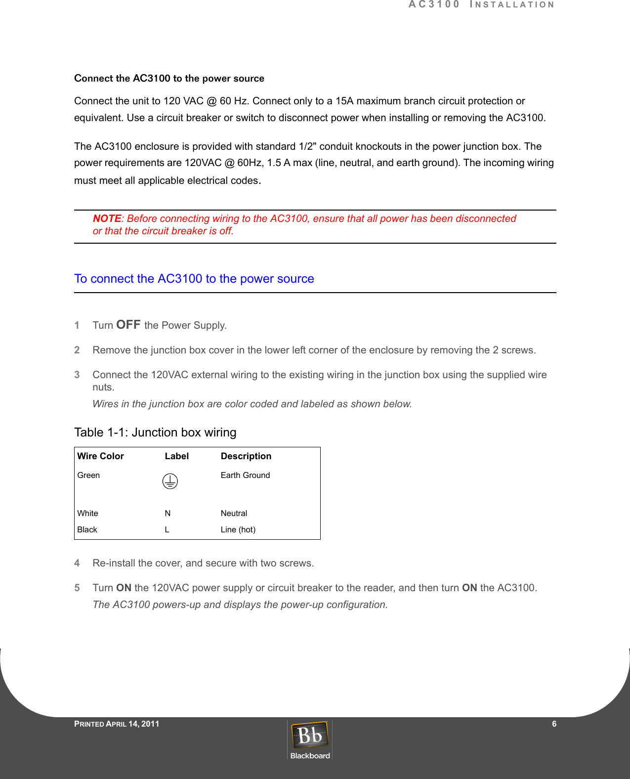
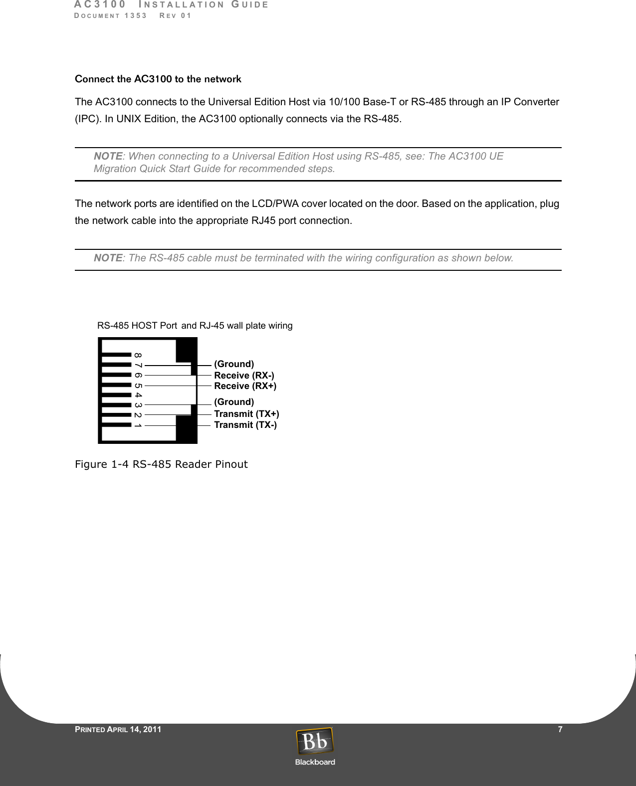
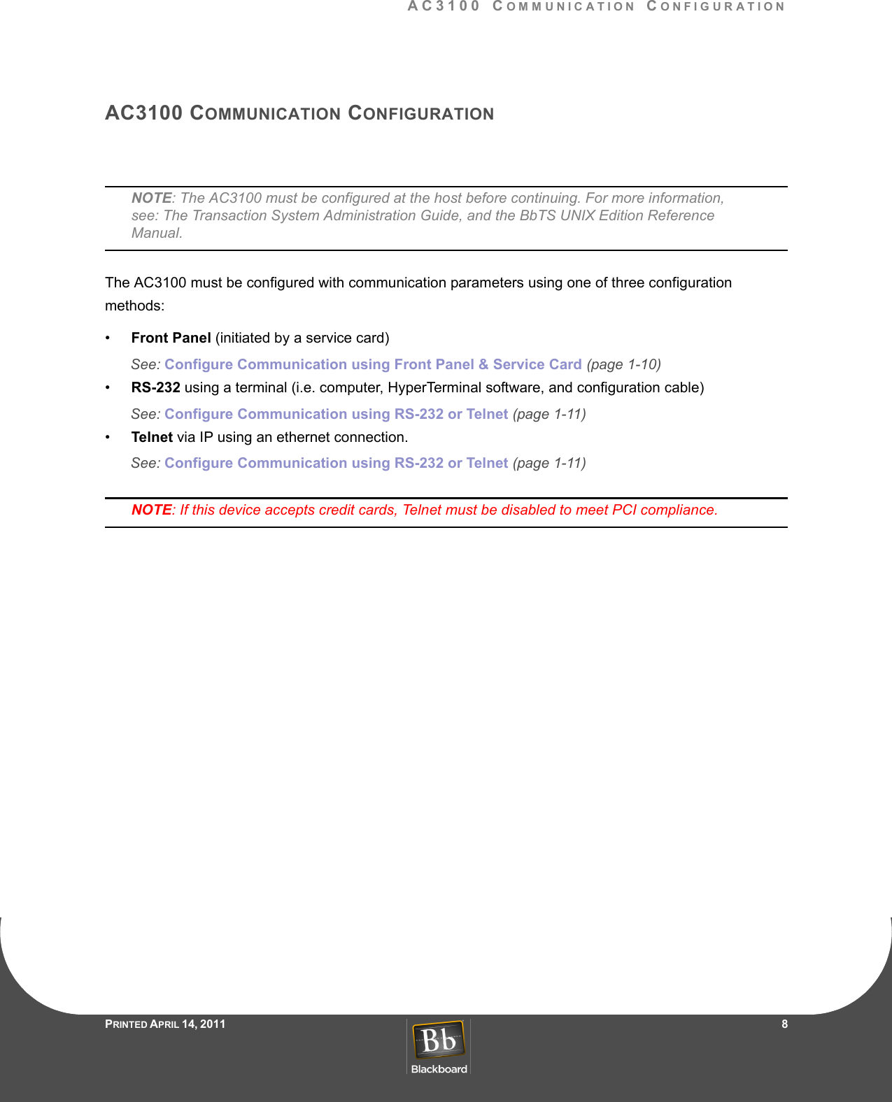
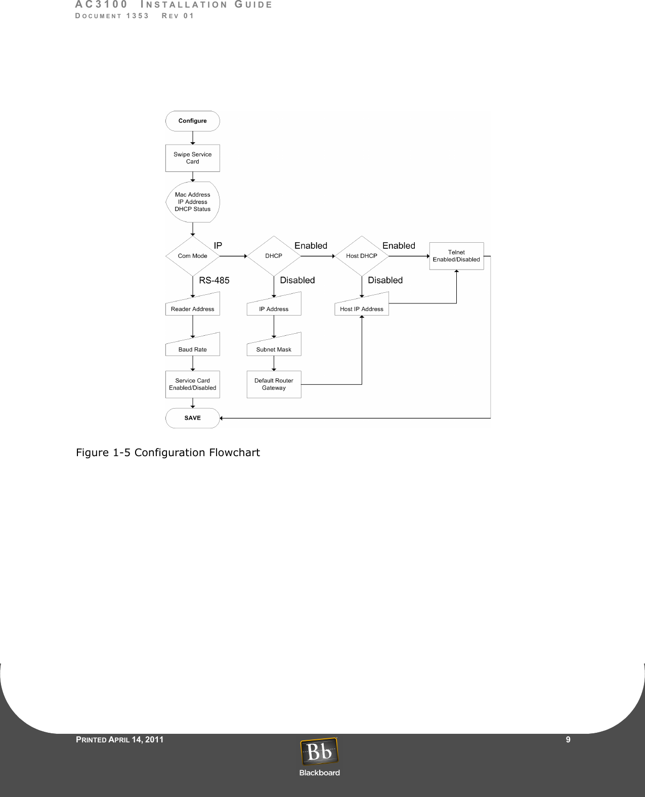
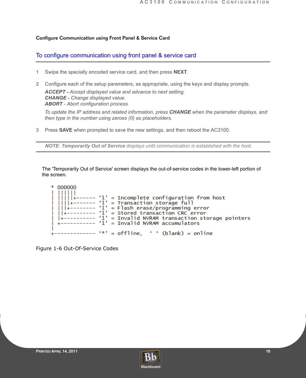
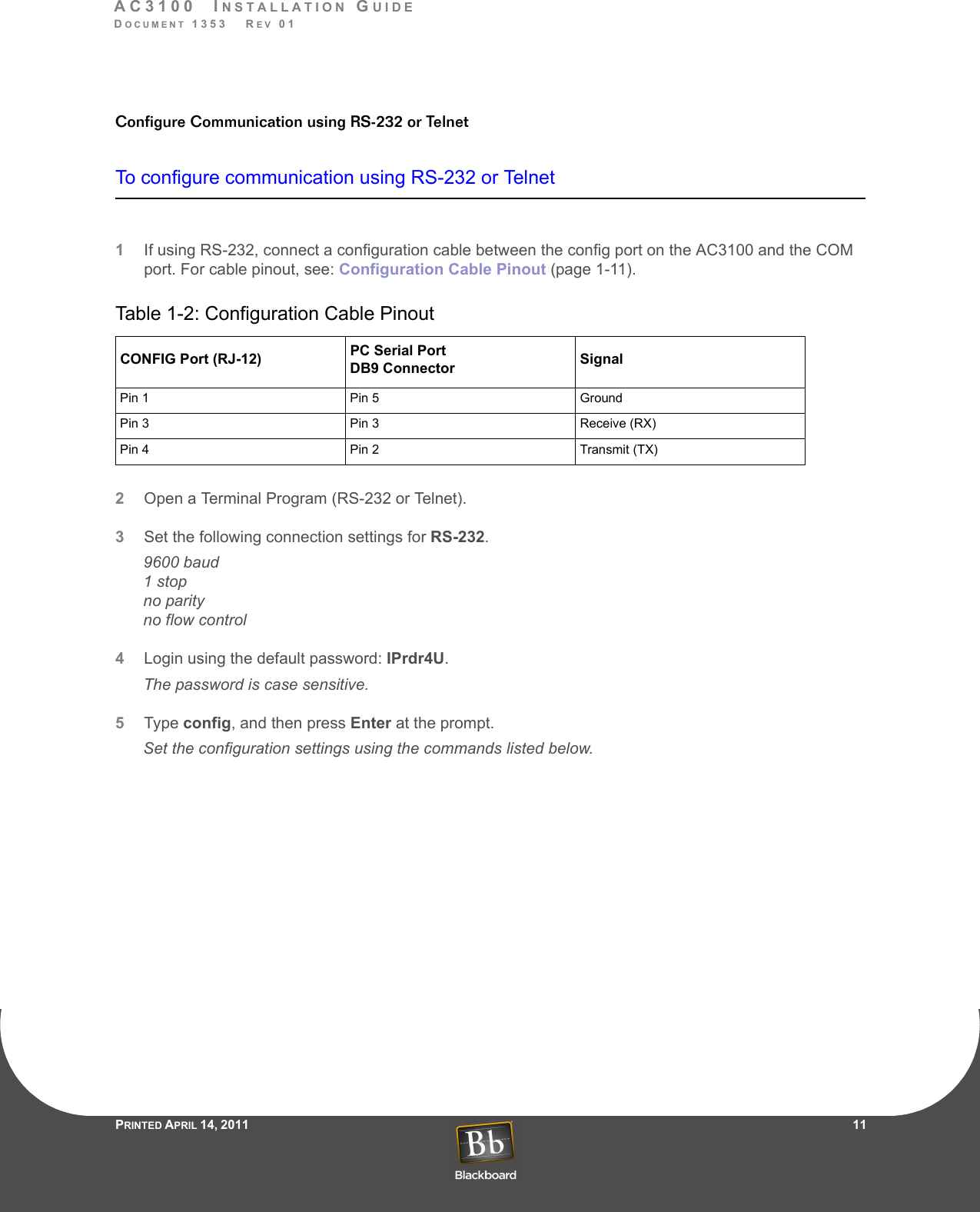
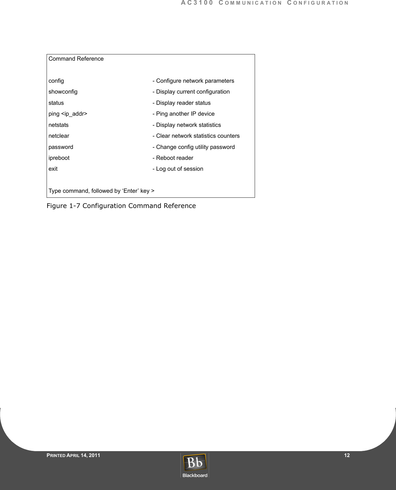
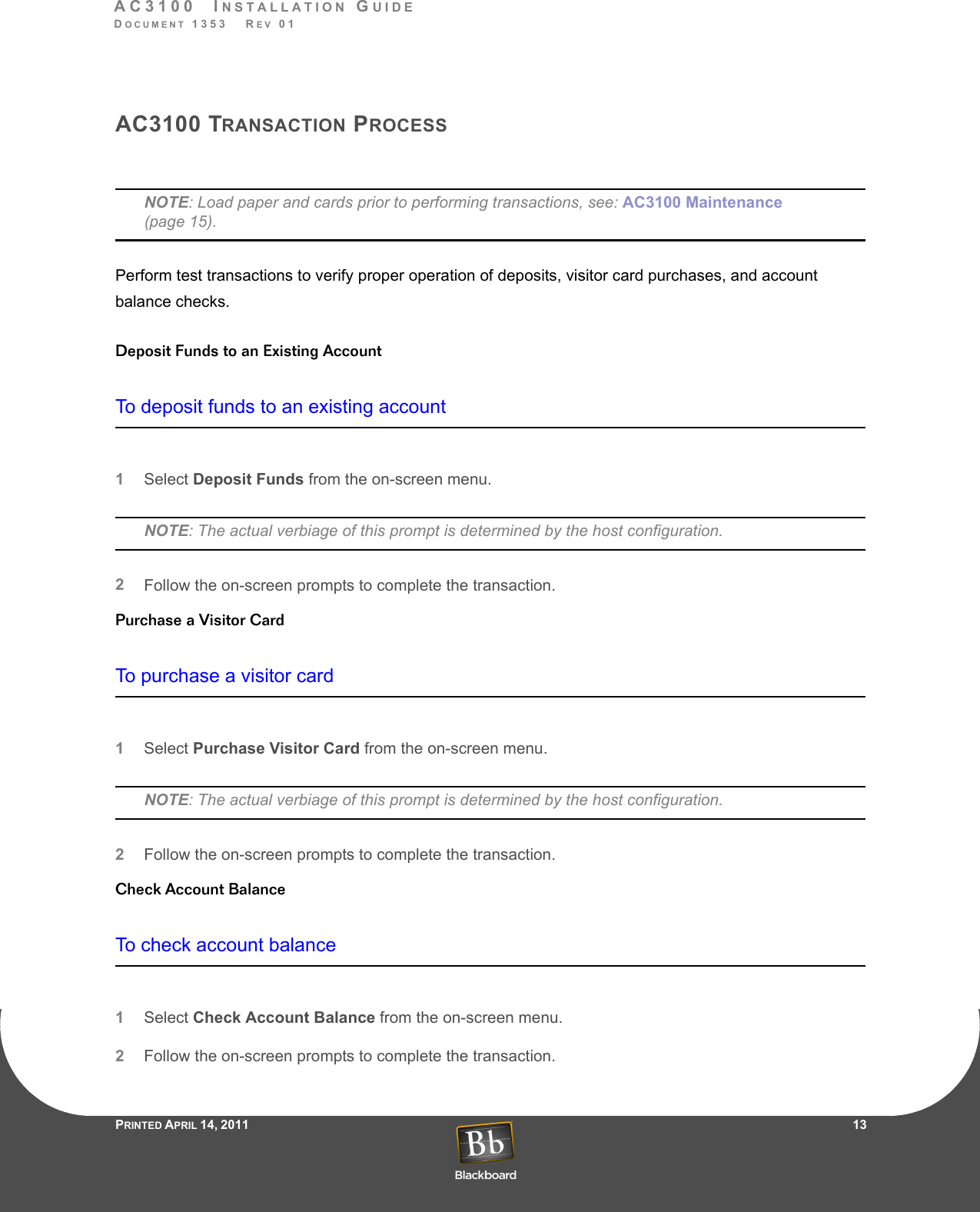
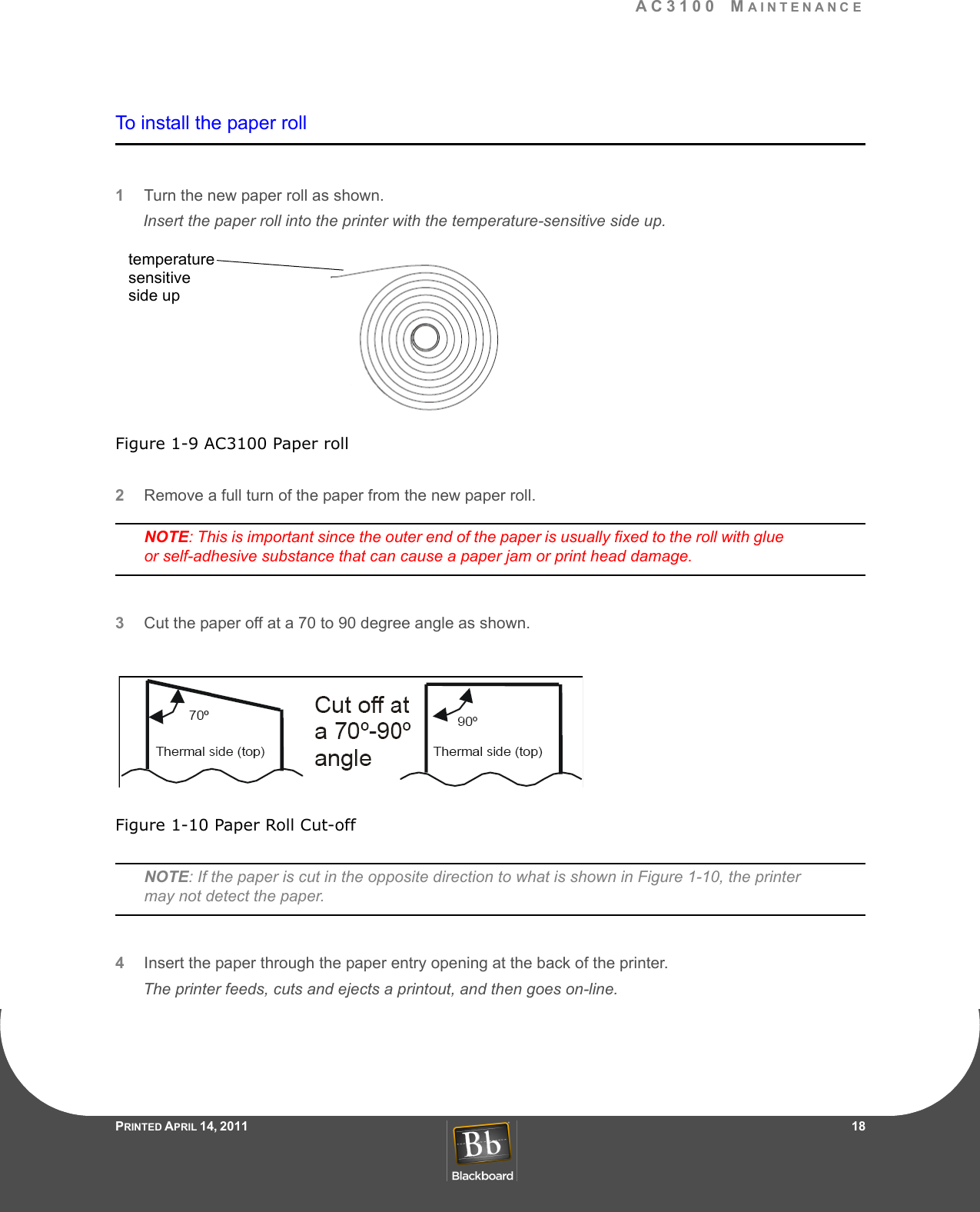
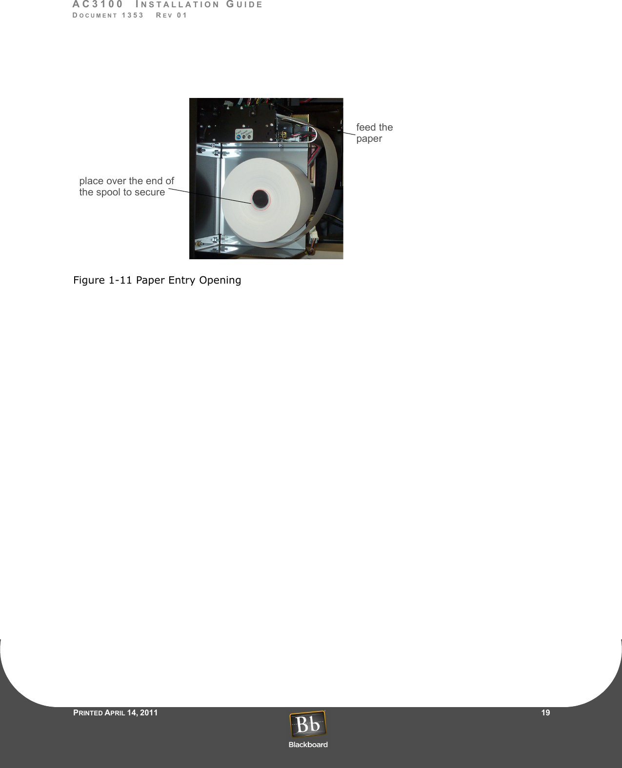
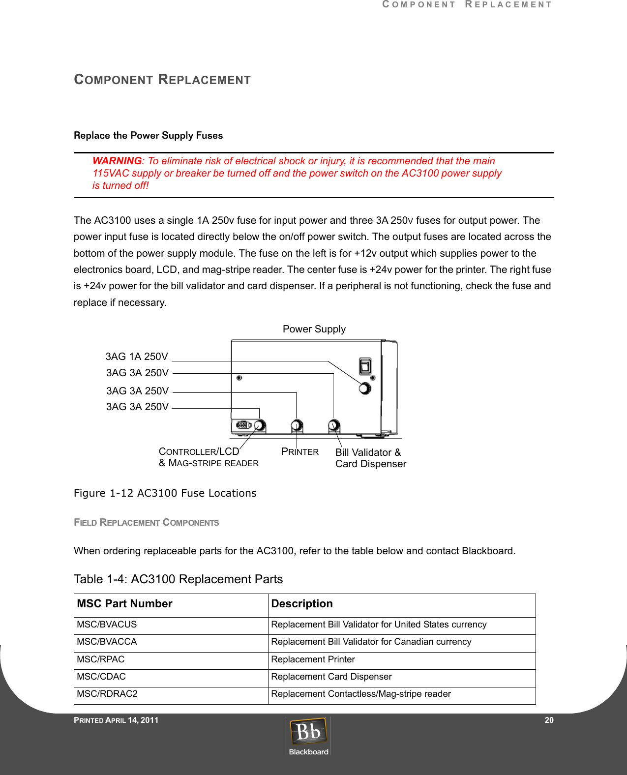
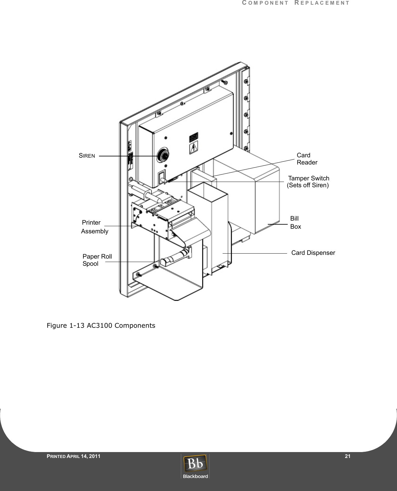
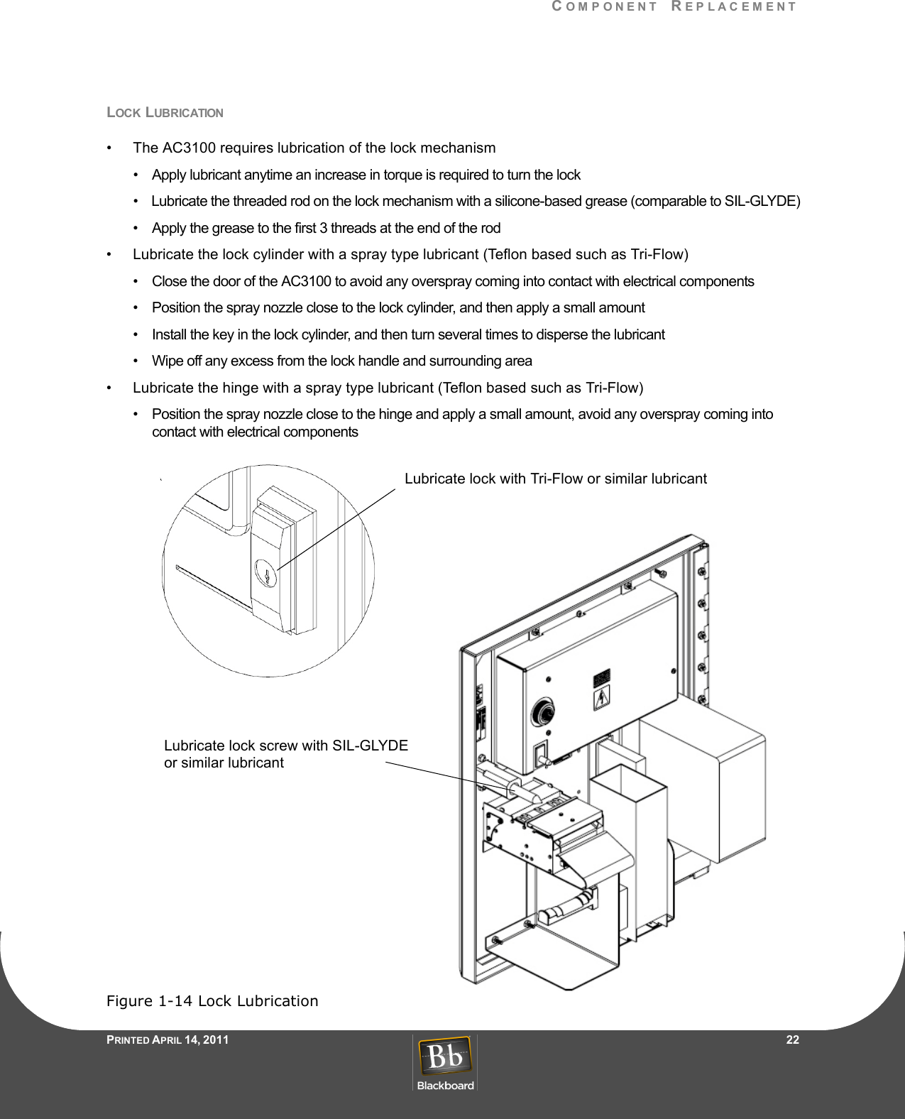
Installation Manual