Blue Ocean Innovation COMMPASS3 JTECH PAGER User Manual 321045B2 QuikCall Pagers
Blue Ocean Innovation Limited JTECH PAGER 321045B2 QuikCall Pagers
Users Manual
Pager and Charger Guide
Part Number 321045B5
Premises Pager System®
QuikCall™ Pagers
2
Introduction:
Congratulations on your purchase of a JTECH Paging System. Please take a
few minutes to review this manual prior to installing and operating your system.
Please inspect the System upon receipt. If the contents appear to be damaged,
notify the shipper immediately to file a claim and notify JTECH Customer Care.
If any component is missing, please contact JTECH Customer Care.
If you have any questions or need assistance, please call JTECH Customer
Care at 800-321-6221 or 561-997-0772, option 6.
Pager Certifications:
FCC statement:
This device complies with Part 15 of the FCC Rules. Operation is subject to the
following two conditions: (1) this device may not cause harmful interference,
and (2) this device must accept any interference received, including interference
that may cause undesired operation.
FCC Caution:
Changes or modifications not expressly approved by the part responsible
for compliance could void the user's authority to operate the equipment.
RSS-Gen & RSS-210 statement:
This device complies with Industry Canada licence-exempt RSS standard(s).
Operation is subject to the following two conditions: (1) this device may not
cause interference, and (2) this device must accept any interference, including
interference that may cause undesired operation of the device. Le présent
appareil est conforme aux CNR d'Industrie Canada applicables aux appareils
radio exempts de licence. L'exploitation est autorisée aux deux conditions
suivantes : (1) l'appareil ne doit pas produire de brouillage, et (2) l'utilisateur de
l'appareil doit accepter tout brouillage radioélectrique subi, même si le
brouillage est susceptible d'en compromettre le fonctionnement.
RSS-102 Statement:
"This equipment complies with Industry Canada radiation exposure limits set
forth for an uncontrolled environment. "
"Cet équipement est conforme à l'exposition aux rayonnements Industry
Canada limites établies pour un environnement non contrôlé.
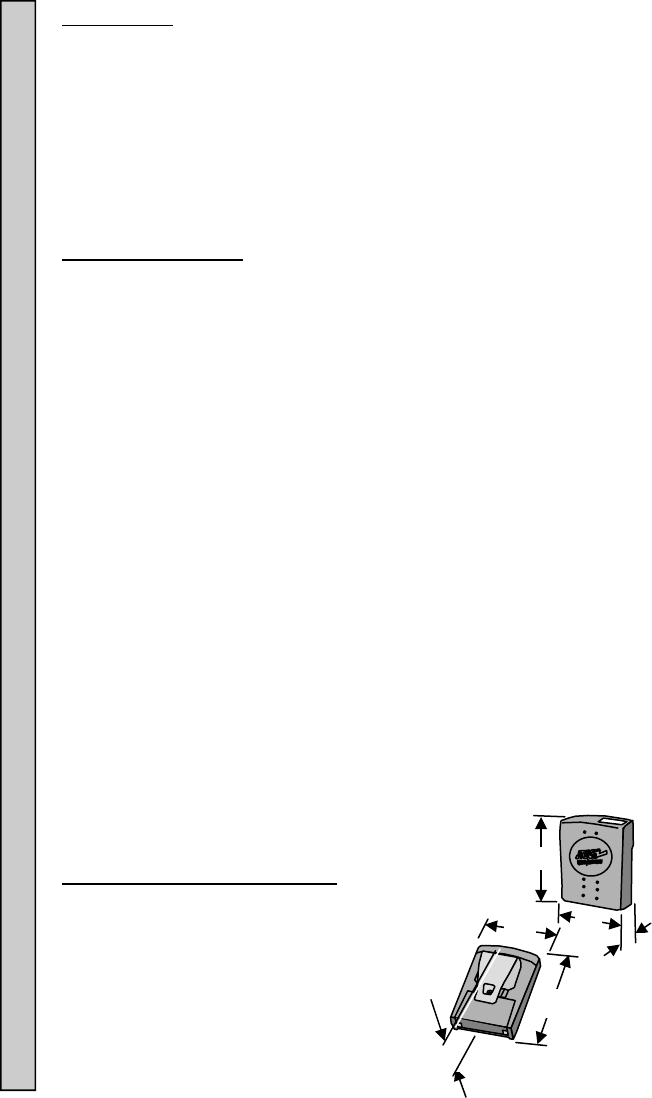
Pager Dimensions and Weights:
Pager (Without Clip)
LxWxH 1.0x 2.2x 3.1” (33x56x79mm)
Weight 2.2oz (63gm)
Pager (With Metal Clip):
LxWxH 1.4x 2.2x 3.1” (35x56x79mm)
Weight 2.8oz (80gm)
Pager Dimensions and Weights Certifications Introduction
H
W
L
L
W
H
3
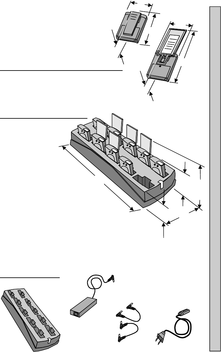
Pager (With Spring Clip):
LxWxH 1.4x 2.2x 3.8” (35x56x97mm)
Weight 2.6oz (74gm)
Pager (With Promotional Paddle And Inserts):
LxWxH 1.2x 2.2x 7.7” (31x56x196mm)
Weight 4.4oz. (124gm)
Charger Dimensions and Weight
Charger Only
LxWxH 13.5x 4.8x
2.6” (343x122x65mm)
Weight 1.64lbs (0.75kg)
Charger and 10 Pagers With Clips:
LxWxH1 13.5x 4.8x 4” (343x122x102mm)
Weight 3.41lbs (1.55kg)
Charger and 10 Pagers With Promotional Paddles:
LxWxH2 13.5x 4.8x 8.8” (343x122x224mm)
Weight 4.38lbs (1.99kg)
Charger Components:
2.4 A Power
Adapter
Jumper Wires
(Optional Equipment)
AC Power
Cord
H
W
L
JTECH
H
W
L
10 Position
Charger
W
L H1 H2
H
Charger Components Define what transmitter is to be used. Note:
4
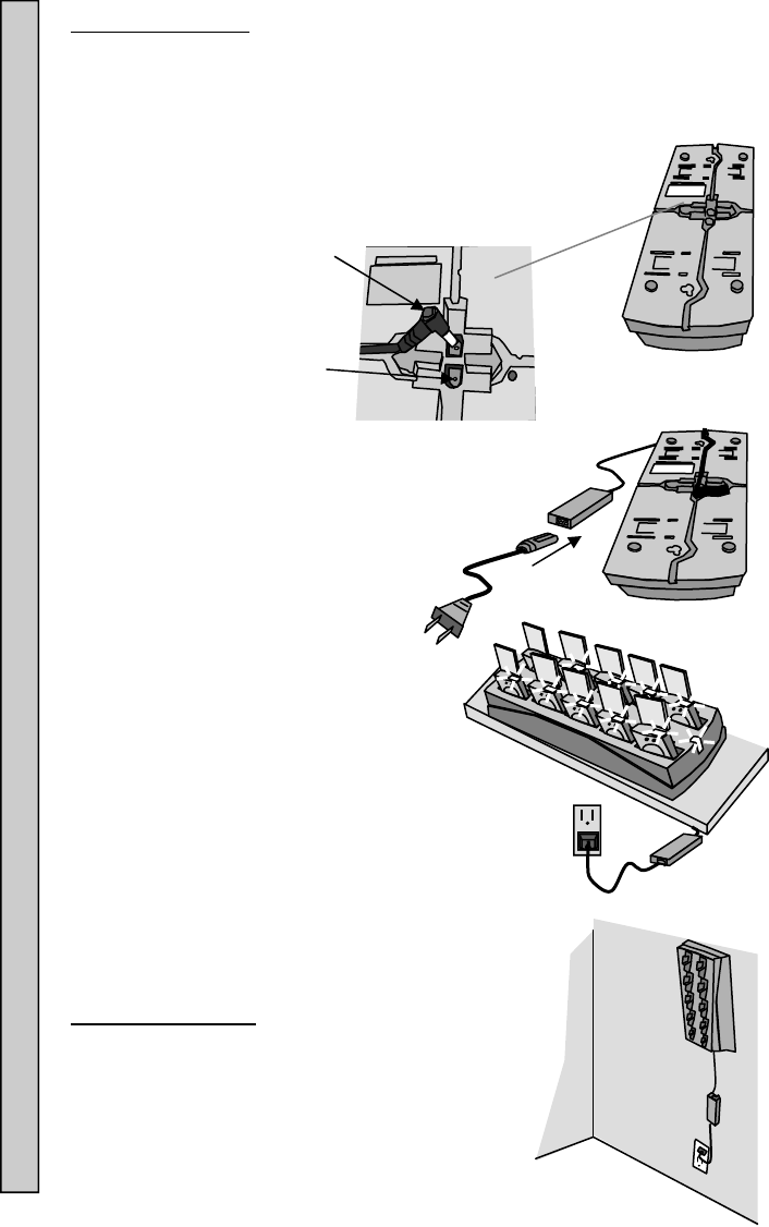
Power
Adapter
Plug
Charger
Jack
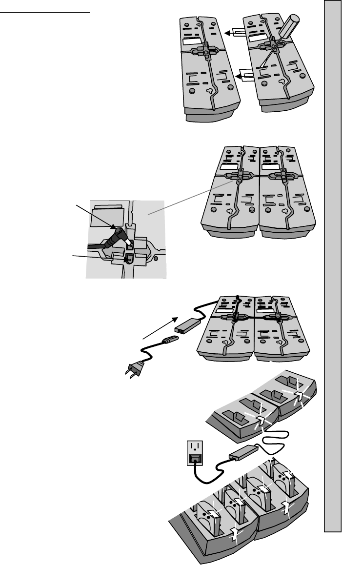
Connecting Power:
1. Insert the Power Adapter plug into jack on the bottom of
the Charger.
2. Feed the wires through the guides in the bottom of the
Charger.
3. Connect the Power Adapter to the AC
Power Cord.
4. Plug the AC Power Cord into a
110-240VAC outlet.
5. The green LED on the Charger will light
(ON).
6. Once the Charger is powered (ON), the
Pagers can be inserted.
Mounting Chargers:
Chargers can be wall, shelf or counter top
mounted.
Mounting hardware is user supplied.
Mounting Chargers Connecting Power to Chargers
5
Combining Chargers:
If two Chargers are to be used, they can be
combined with one 2.4A Power Supply.
To combine:
1. Use a screwdriver or similar tool to extend
the metal tabs out from one of the
Chargers.
2. Place both Chargers on a table and slide
together. The metal tabs will lock both
Chargers together.
3. Insert the Power Adapter plug into jack on the
bottom of the Charger.
4. Use the Jumper Wire (optional) to
connect both Chargers together.
5. Feed the wires through the guides
in the bottom of the Charger.
6. Connect the Power Adapter to
the AC Power Cord.
7. Plug the AC Power Cord into a
110-240AC outlet.
8. The green LED on the Charger will
light (ON).
9. Once the Charger is
powered (ON), the Pagers
can be inserted.
Combining Chargers
Power
Adapter
Plug
Charger
Jack
6
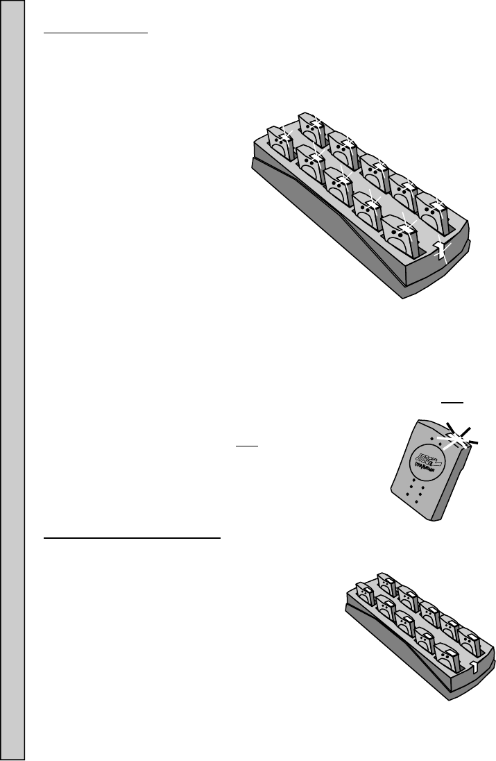
Charging Pagers:
Pagers are turned OFF during shipment from JTECH.
When first received, Pagers must be charged for a minimum of 3 hours prior
to use. This first charge will also turn ON the Pagers for use.
The charging system is two stage, with a fast initial and then final
maintenance charge.
Charging Pagers:
1. Insert Pagers into the
empty locations of a
powered (ON) Charger.
2. Each Pager’s LED will light.
3. The LED color indicates charging condition.
Flashing yellow light = Battery charge very low. Charge needed.
Do not use the Pager.
Solid yellow light = Charge needed.
Solid green light = OK to use.
4. Pagers in use and returned to the Charger within 24 hours will fully
charge within three hours.
5. If not returned within 24 hours, charging time of up to 8
hours may be required to fully charge batteries.
6. When not in the Charger, each Pager continues to
indicate battery charge condition:
Flashing yellow light = Charge needed.
Flashing green light = OK to use.
Charging and Storing Pagers:
To maintain maximum battery capacity, store Pagers in the powered (ON)
Charger.
If Pagers are left uncharged for more than 4
days, it is recommended to disconnect the
batteries until their next use. See “Replacing the
Battery” on page 11 for instructions.
If left uncharged for extended periods of time, Pager
batteries can damage beyond repair and will need to be
replaced.
When charged and stored properly, a battery life of 18-24
months can be expected before replacement is suggested.
Charging and Storing Pagers Connecting Power to Chargers
7
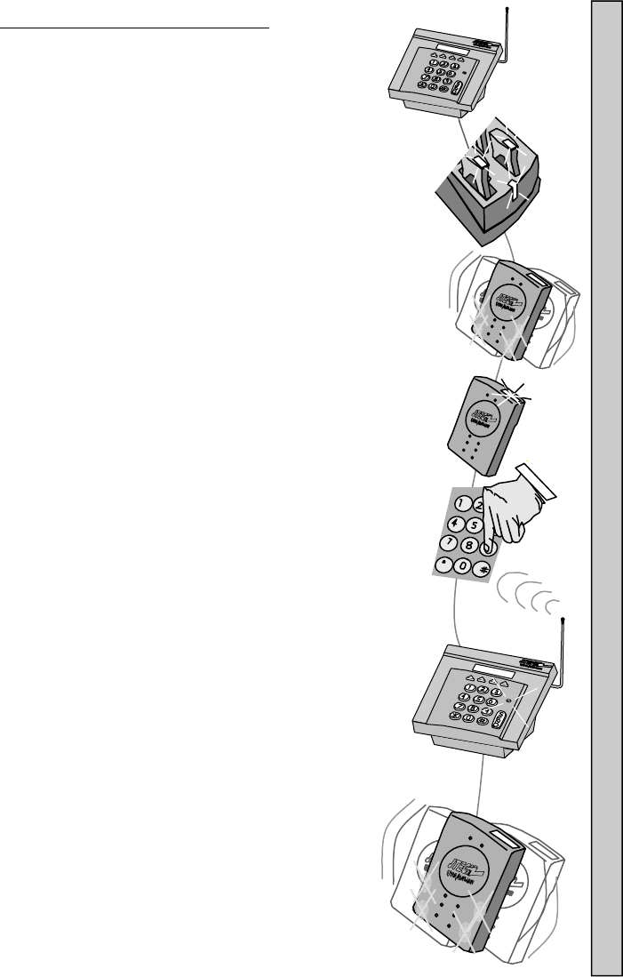
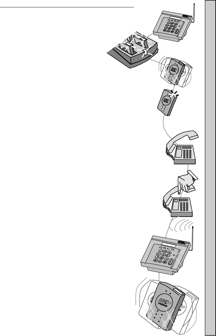
Paging Using a Desktop Controller:
1. Remove a Pager from the Charger.
2. The Pager will vibrate and it’s LEDs will flash to confirm it
is ready for use.
3. The Pager charge LED will continue to flash, confirming
the it is ready to receive a page.
4. Enter the number of the Pager on the Controller.
5. Press # or SEND button to send the page.
6. The XMIT light on the Controller will turn ON, confirming
the page is being sent.
7. The Pager will vibrate, tone or flash as required.
8. See “Enter Pager #” Menu instructions in your
Desktop Controller manual for more
information.
Paging Using a Desktop Controller
8
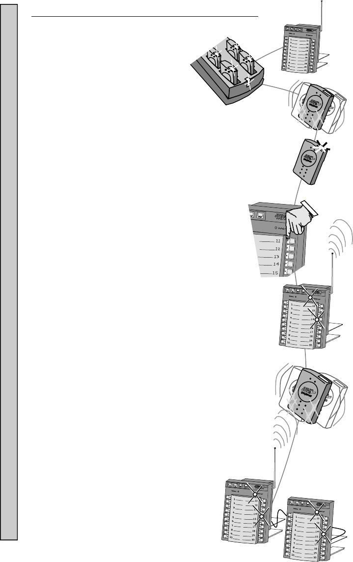
Paging Using a Kitchen Controller or Expeditor Panel:
1. Remove the Pager you wish to
page from the Charger.
2. The Pager will flash and vibrate
to confirm it is ready for use.
3. The Pager charge LED will continue to flash, confirming it is
ready to receive a page.
4. Press the number on the Controller or Expeditor Panel of the
Pager.
5. The light on the panel, next to that number will
turn ON.
6. The XMIT light will turn ON for 2-3 seconds and turn off.
7. The Pager will receive a single, one second vibration
(factory setting).
8. The light on the panel, next to that Pager number will
continue to stay ON for 40 seconds (factory setting).
9. If a Controller and Expeditor Panel are combined,
pressing a button on either panel will light both panels.
10. After 40 seconds (factory setting), the light next to the
number pressed will begin to blink on the Panel or
Panels for an additional 40 seconds (factory
setting), before turning off.
11. See Paging instructions in your Kitchen
Controller manual for more information.
Paging Using a Kitchen Controller or Expeditor Panel
9
Paging Using a Desktop Controller and Telephone:
(Telco Module must be installed)
1. Remove the Pager you wish to page from
the Charger.
2. The Pager will flash and vibrate to confirm it is ready for
use.
3. The Pager charge LED will continue to flash, confirming it is
ready to receive a page.
4. Pick up the phone and listen for the dial tone.
5. Dial the phone number that has been assigned to the TELCO
Module installed.
6. Listen for a voice message from the telephone that confirms
the Controller is ready.
7. Within 8-10 seconds, using the telephone keypad, enter the
Pager number (up to 4 digits) and press the # button to send
the page.
8. A voice message heard on the phone confirms the message
was sent.
9. Hang up the telephone.
10. The Pager will receive a single, one second
vibration (factory setting).
11. See Paging instructions in your Desktop Controller
manual for more information.
Paging Using a IntelFlex Desktop Controller with Telco Module
10
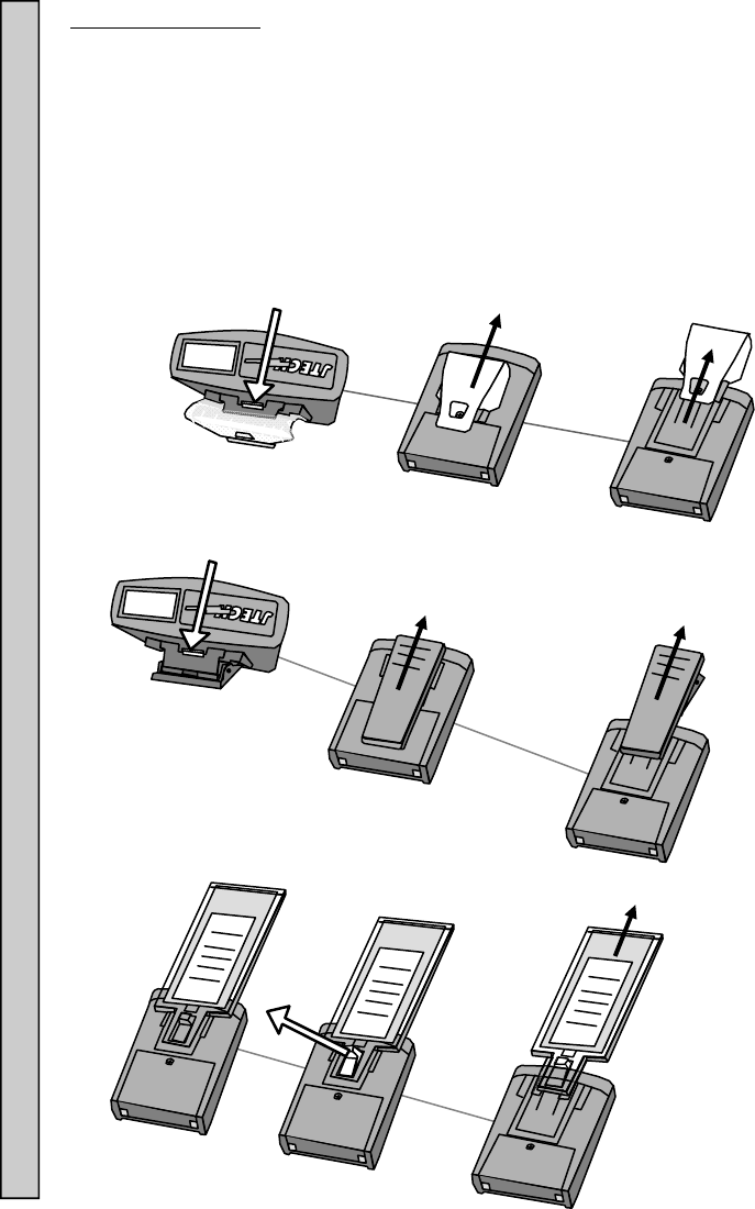
Replacing the Clip :
There are 3 Clip attachments; Metal, Spring or Paddle.
To replace a Clip or Paddle:
1. Turn the Pager over.
2. Push or pull the small plastic tab as shown in below and slide the Clip
or Paddle off.
3. Slide the new Clip or Paddle on until a “click” can be heard, locking the
clip or paddle onto place.
Metal Clip:
Spring Clip:
Paddle:
Replace The Clip
5
JTECH
JTECH
JTECH
5
Push Tab
Push Tab
Pull Tab
Slide
Slide
Slide
11
Loosen
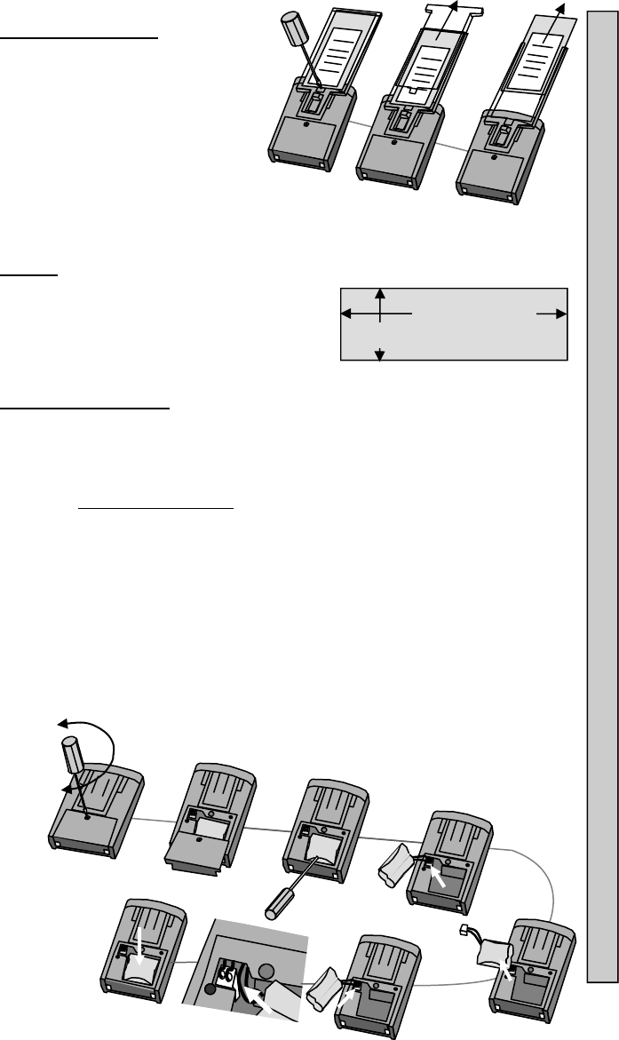
Replacing the Insert:
1. Turn the Pager over.
2. Using a flat blade screwdriver or
equivalent to unlock the clear
plastic cover.
3. Slide the clear plastic cover out.
4. Remove the Insert.
5. Replace with a new Insert.
6. Replace and slide the clear plastic
cover into place. When inserted
completely, the cover will “snap” into place.
7. Replace and tighten the screw (do not over tighten).
Inserts:
Inserts can be professionally printed (call
your JTECH sales representative for more
details).
Material thickness is 0.020” (5.1mm)
maximum.
Replacing the Battery:
1. Batteries that no longer charge properly or have a reduced operating
time can be replaced by the user.
2. If using a Spring Clip, it must be removed to access the battery door
screw.
3. Use a #1 Philips screwdriver to remove the screw.
4. Slide the battery door and Pager Clip off.
5. Carefully slip a screwdriver tip under the plastic wrapper on the battery
pack and lift the battery out.
6. Unplug the battery connector.
7. Dispose of the Nickel Metal Hydride battery pack at any retail
department or home improvement stores that recycles batteries.
8. Plug the new battery into the Pager’s connector.
9. Push excess battery wire into the space next to the connector.
10. Press the battery into the Pager compartment.
11. Replace the battery door, clip and screw (do not over tighten).
12. Insert the Pager into the Charger and fully charge the battery.
Insert Dimensions
4-1/2” (114.3mm)
1-7/8” (47.6mm)
Replacing the Battery Inserts
JTECH
JTECH
JTECH
Tighten

12
6413 Congress Avenue
Suite 150
Boca Raton, Florida 33487
800-321-6221
Part Number 321045B5
© 2012, JTECH Communications, Inc. All Rights Reserved.
SYSTEM WARRANTY
JTECH Communications, Inc. warrants its equipment to be free from
defects in materials and workmanship for a period of one year. Its
obligation under this warranty is limited to repairing or replacing, at its
own sole option, any such defective products. Products must be
returned with transportation charges prepaid. All warranty returns
must also include a JTECH-issuesd RMA number, clearly displayed
on the interior and exterior of the package(s). This warranty does not
apply to equipment which has been damaged by accident,
negligence or misapplication or has been altered or modified in any
way. This warranty applies only to the original purchaser.
The following are not covered under our one-year warranty: adapters,
antennas, user-replaceable batteries, pager belt clips, pager
promobacks, pager battery doors, or pager neck chains. Warranty
also excludes liquid damage to master transmitter/controller
(including base station, modules and any desktop or rack mount
appliances), pagers, chargers or tablet hardware, lightning strikes or
other acts of God that could affect the performance of the master
transmitter/controller, pagers and peripherals.