Blue Ocean Innovation COMMPASS467 JTECH PAGER User Manual 321032A5 1 CommPass Pagers
Blue Ocean Innovation Limited JTECH PAGER 321032A5 1 CommPass Pagers
Manual
1
Pager and Charger Guide
Part Number 321032B4
Premises Pager System®
CommPass® Pagers
GuestPass™ Pagers
MediPass™ Pagers
ShopperPass™ Pagers
34
34
34
7
34
18
2
Introduction:
Congratulations on your purchase of the JTECH Paging System. Please take a
few minutes to review this manual prior to installing and operating your system.
Please inspect the System upon receipt. If the contents appear to be damaged,
notify the shipper immediately to file a claim and notify JTECH Customer Care.
If any component is missing, please contact JTECH Customer Care.
If you have any questions or need assistance, please call JTECH Customer
Care at 800-321-6221 or 561-997-0772, option 6.
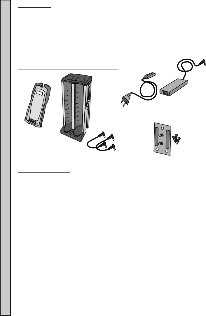
CommPass Pager System Components:
Pager Certifications:
FCC statement:
This device complies with Part 15 of the FCC Rules. Operation is subject to the
following two conditions: (1) this device may not cause harmful interference,
and (2) this device must accept any interference received, including interference
that may cause undesired operation.
FCC Caution:
Changes or modifications not expressly approved by the part responsible
for compliance could void the user's authority to operate the equipment.
RSS-Gen:
This device complies with Industry Canada licence-exempt RSS standard(s).
Operation is subject to the following two conditions: (1) this device may not
cause interference, and (2) this device must accept any interference, including
interference that may cause undesired operation of the device. Le présent
appareil est conforme aux CNR d'Industrie Canada applicables aux appareils
radio exempts de licence. L'exploitation est autorisée aux deux conditions
suivantes : (1) l'appareil ne doit pas produire de brouillage, et (2) l'utilisateur de
l'appareil doit accepter tout brouillage radioélectrique subi, même si le
brouillage est susceptible d'en compromettre le fonctionnement.
AC Power
Cord
Jumpers
Pager Certifications Components Introduction
CommPass
Pager with
Standard Insert
3
2.4 A or
7.3A (Optional)
Power Adapter
Charger with
Key Attached
Mounting
3
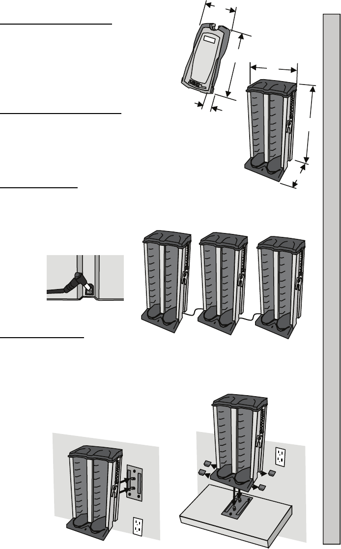
Pager Dimensions/Weight:
LxWxH 5.4x 2.3x 0.9” (137x58x23mm)
Weight 3.5oz (99gm)
Charger Dimensions/Weight:
LxWxH 7.3x 6.9x 13.1” (184x176x333mm)
Weight (Empty) 6.6lbs (3.0Kg)
Weight (With 20 Pagers) 11.0lbs (5.0Kg)
Multiple Chargers:
A single Charger can hold up to 20 Pagers.
Combine two or three Chargers using the optional Jumpers and 7.3A
Power Adapter.
Mounting Chargers:
Chargers can be wall or counter top mounted using the supplied Mounting
Plate.
Wood screws are include for table or shelf mounting.
If mounted to a shelf or table, the four rubber feet on the bottom of the
Charger must be removed.
Wall anchor hardware is user supplied.
3
W
L
H
Mounting Chargers Multiple Chargers Pager and Charger Dimensions/Weight
W
H
L
4
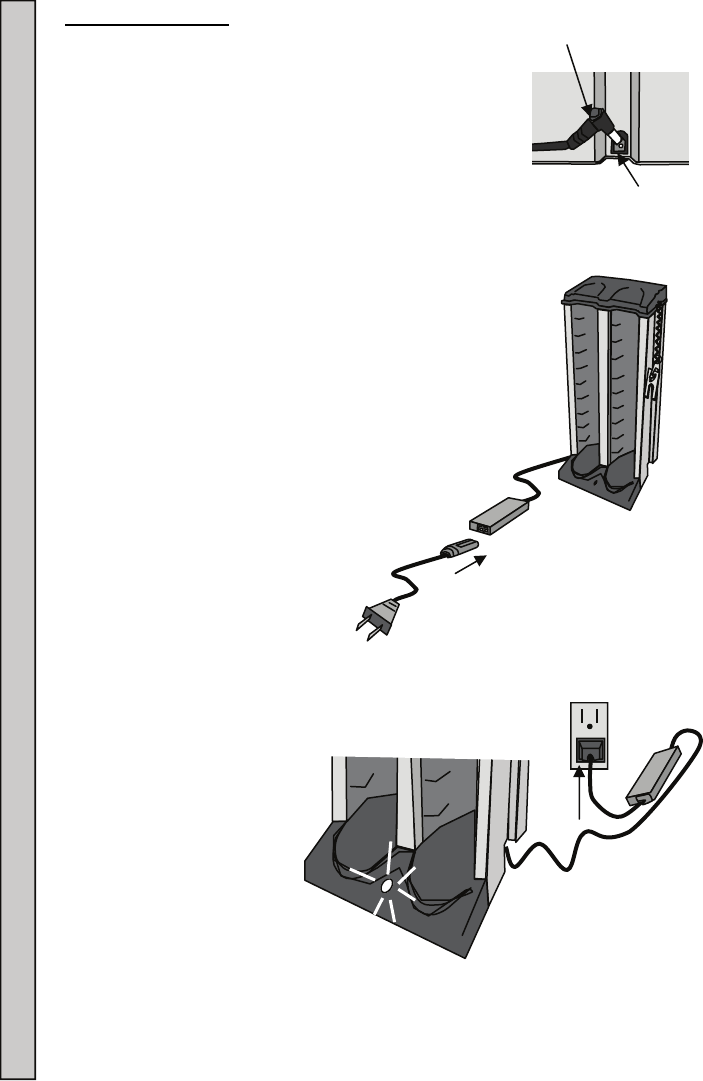
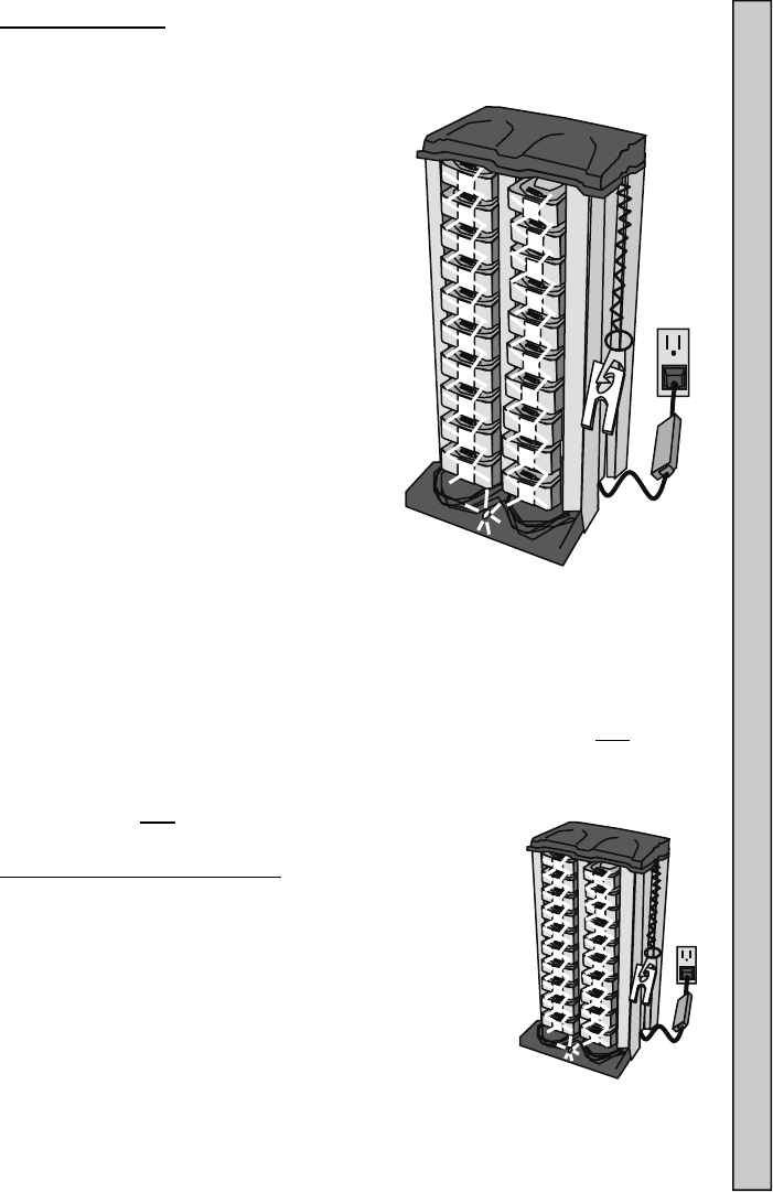
Connecting Power:
1. Insert the Power Adapter plug into the jack at the
bottom of the Charger.
2. Connect the Power Adapter to the Power Cord.
3. Plug the Power Cord into a 120VAC outlet.
4. The green LED on the Charger will light (ON).
5. Once the Charger is ON, the Pagers can be inserted.
Power
Adapter
Plug
Charger
Jack
120VAC
Outlet
Charging
Rack
Adapter
Power Cord
Connecting Power to the Charger
5
Charging and Storing Pagers Charging Pagers
Charging Pagers:
Pagers are turned OFF for shipment from JTECH.
When first received, Pagers are to be charged for a minimum of 3 hours
prior to use.
This first charge will also turn ON the
Pagers.
To charge:
1. Insert Pagers into the empty Charger
locations.
2. Once in the powered (ON) Charger,
each Pager’s LED will light:
3. The LED color indicates charging
condition.
Flashing yellow light = Battery
charge very low. Charge
needed. Do not use the Pager.
Solid yellow light = Charge
Needed.
Solid green light = OK to use.
The charging system is two stage, with a fast initial charge and then a final
maintenance charge.
Pagers in use and returned to the Charger within 24 hours will fully charge
within three hours.
If not returned within 24 hours, charging time of up to eight hours may be
required to fully charge batteries.
Charging and Storing Pagers:
To maintain maximum battery capacity, store Pagers
in the powered (ON) Charger.
If Pagers are left uncharged for more than 4 days, it is
recommended to disconnect the batteries until their
next use. See “Replacing the Battery” on page 10
for instructions.
If left uncharged for extended periods of time, Pager
batteries can damage beyond repair and will need to be
replaced.
When charged and stored properly, a battery life of 18-24 months can be
expected before replacement is suggested.
1
0
9
8
7
6
5
4
3
2
1
20
19
18
1
16
15
14
13
12
11
1
9
8
7
6
5
4
3
2
1
2
1
1
1
1
1
1
1
1
1
6
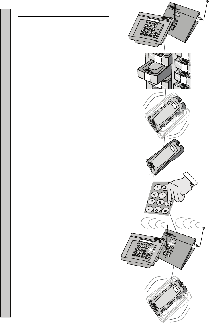
Paging Using a Desktop Transmitter:
1. Remove the Pager you wish to page from the
Charger.
2. The Pager will flash and vibrate to confirm it is
ready for use.
3. The Pager LED in the front of the Pager will
continue to flash every 3-4 seconds to confirm the
Pager is ON and ready to accept a page.
4. Enter the number of the Pager you wish to page on
the Transmitter or Remote Keypad.
5. Press # to send the page. Press the # or SEND
button if using an IntelFlex Desktop Transmitter.
6. The XMIT light on the Transmitter will turn ON,
confirming the page is being sent. If using a
Remote Keypad, the Keypad XMIT light does not
ON.
7. The Pager will vibrate, flash tone or
speak as required.
8. See “Enter Pager #” Menu Functions in your
Transmitter manual for more information.
Paging Using a Desktop Transmitter
3
3
3
3
3
7
16
15
6
5
14
3
3
3
7
7
16
15
6
5
14
5
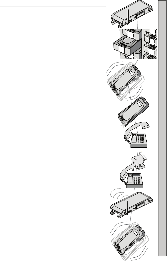
Paging Using a 8205 or 8214 SmartAlert with RS232
and Telephone Transmitter Paging using the
Telephone:
1. Remove the Pager you wish to page from the Charger.
2. The Pager will flash and vibrate to confirm it is
ready for use.
3. The Pager charge LED will continue to flash, confirming
it is ready to receive a page.
4. Pick up the telephone and listen for the dial tone.
5. Dial the telephone number that has been assigned to
the Transmitter.
6. Listen for a beep from the telephone that confirms the
Transmitter is ready.
7. Within 8-10 seconds, use the telephone keypad:
a. Enter the Pager number (up to 4 digits).
b. Press the # key to send the page.
8. A beep will be heard on the telephone that confirms
the message was sent.
9. Hang up the telephone.
10. The Pager will receive a single, one second
vibration (factory setting).
11. See Paging instructions in your Transmitter manual
for more information.
Paging Using a 8205 or 8214 SmartAlert with RS232 and Telephone Transmitter
3
3
3
3
3
3
3
3
8
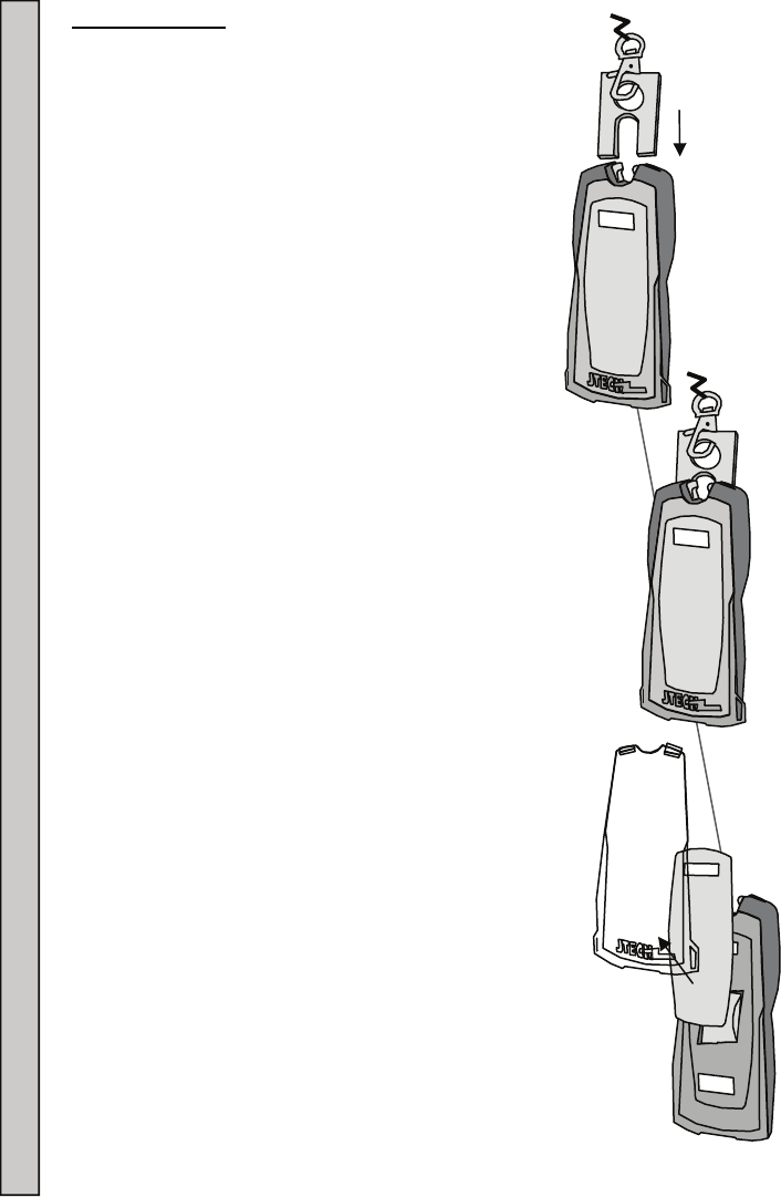
Replace Inserts:
1. Insert the KEY into the slots on the end of the Pager,
until the Clear Plastic Cover unlocks.
2. Remove the Clear Plastic Cover and Insert.
3. Replace the Insert and “snap” the Clear Plastic Cover
back into place.
5
34
34
5
34
34
34
Replacing Pager Inserts
9
Blank Inserts:
Blank Promotional Sheets can be ordered from JTECH as needed.
Sheets contain eight Inserts per sheet and perforated for removal.
Sheets are white in color and can be printed on using a standard
printer.
Custom Inserts can also be professionally printed (call your JTECH
sales representative for more details).
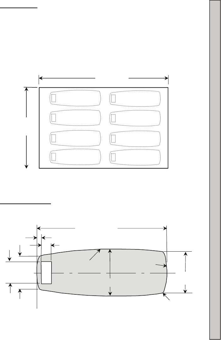
Insert Dimensions:
8 1/2”
(215.9m
11” (279.4
0.12”R
(3mm R)
1.25”R Typ.
(31.7mm R)
15.0”RTyp.
3.90” (99.1mm)
Cut Out
Material Thickness 0.02” (0.5mm) Max
0.30” (7.6mm)
C
L
1.05”
(26.7mm)
0.70”
(17.8mm)
0.12” (3.05m)
1.40” (35.6mm)
1.20”
(30.5mm)
Insert Dimensions Blank Inserts
10
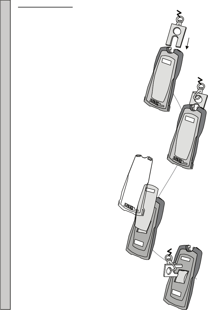
Replacing the Battery:
Batteries that no longer charge properly or have a reduced
operating time can be replaced by the user.
Replacement battery packs can be ordered from JTECH.
To replace:
1. Insert the Key into the slots on the end of the
Pager until the Clear Plastic Cover unlocks.
2. Remove the Clear Plastic Cover and
Insert.
3. Insert the Key into the space on the left side of the
battery compartment and carefully pry the battery out.
Replacing the Battery
5
34
6
6
5
34
6
6
11
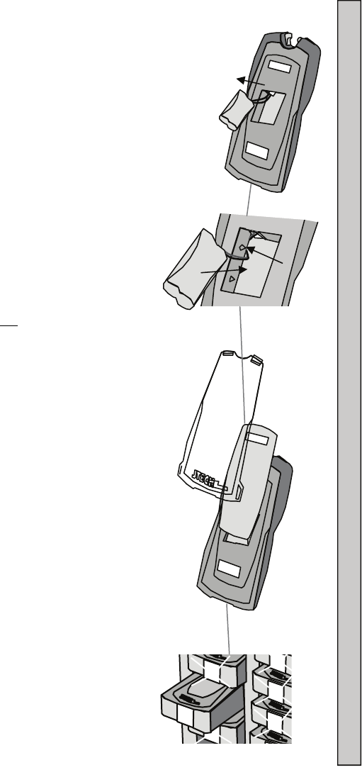
4. Unplug the battery from the Pager.
5. Dispose of the Nickel Metal Hydride battery pack at
any retail department or home improvement stores
that recycles rechargeable batteries.
6. Plug the new battery pack into the Pager.
7. Move any excess wire to the into the
compartment’s left side while inserting
the battery into the Pager.
8. Battery wires must be on the left side of
the Pager and not under the battery to
assemble the pager properly.
9. Replace the Insert and “snap” the Clear
Plastic Cover back into place.
10. Insert the Pager into the Charger and fully
charge the battery.
Replacing the Battery
7
16
15
6
5
14
5
6
6

12
6413 Congress Avenue
Suite 150
Boca Raton, Florida 33487
800-321-6221
Part Number 321032B4
© 2012, JTECH Communications, Inc. All Rights Reserved.
SYSTEM WARRANTY
JTECH Communications, Inc. warrants its equipment to be free from
defects in materials and workmanship for a period of one year. Its
obligation under this warranty is limited to repairing or replacing, at its
own sole option, any such defective products. Products must be
returned with transportation charges prepaid. All warranty returns
must also include a JTECH-issuesd RMA number, clearly displayed
on the interior and exterior of the package(s). This warranty does not
apply to equipment which has been damaged by accident,
negligence or misapplication or has been altered or modified in any
way. This warranty applies only to the original purchaser.
The following are not covered under our one-year warranty: adapters,
antennas, user-replaceable batteries, pager belt clips, pager
promobacks, pager battery doors, or pager neck chains. Warranty
also excludes liquid damage to master transmitter/controller
(including base station, modules and any desktop or rack mount
appliances), pagers, chargers or tablet hardware, lightning strikes or
other acts of God that could affect the performance of the master
transmitter/controller, pagers and peripherals.