Blue Ocean Innovation RECHARG3 JTECH PAGER User Manual
Blue Ocean Innovation Limited JTECH PAGER Users Manual
UserManual.wiki
>
Blue Ocean Innovation
>
RECHARG3 User Manual
Users Manual
Navigation menu
Upload a User Manual
Namespaces
Wiki Guide
HTML
PDF
Info
Views
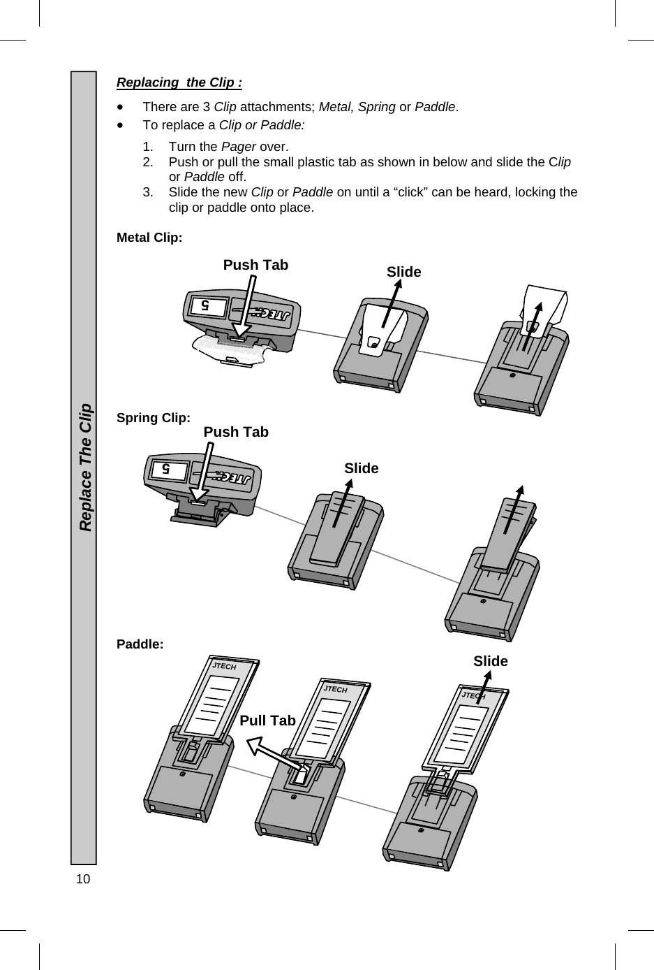
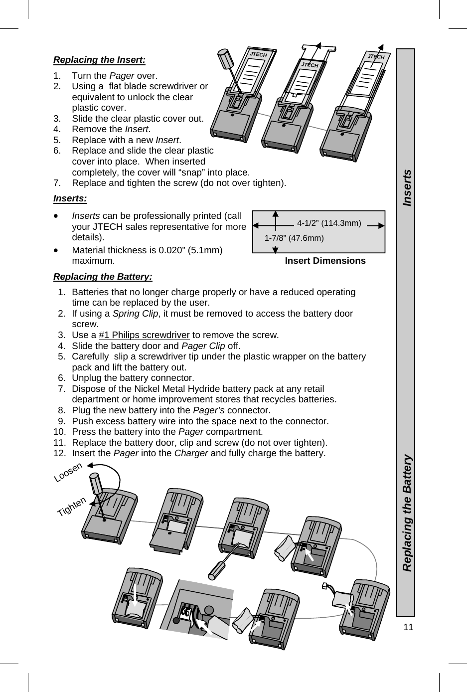
User Manual
Discussion / Help
Navigation