Blue Sun Solutions TRUCKTRACKER VEHICLE TRACKER User Manual
Blue Sun Solutions, LLC VEHICLE TRACKER Users Manual
Users Manual

Redview GPS
www.redview.net
- 1 -Page 1 of 30
VT-200
Automatic Vehicle Locator User Manual
Version 2.0
Add: Room 702,Building A,Tsing Hua high tech park,
Nan Shan District,Shenzhen,China
TEL: 0755- 88846144 0755 - 26030340
FAX: 0755- 26030441
WEB: www.redview.net

Redview GPS
Copyright © Jan. 20, 2006
Redview Inc. All rights reserved.
Redview Document
Printed in China
Redview Inc.
www.redview.net
- 2 -Page 2 of 30
Add: Room 702,Building A, Tsing Hua High tech park,
Nan Shan District, Shenzhen, China
TEL: 0755-26030340 0755-88846144
FAX: 0755-26030441
WEB: www.redview.net
Notice
This manual, as well as the software described in it, is furnished under license and may be
used or copied only in accordance with the terms of such license. The content of this manual
is furnished for informational use only, is subject to change without notice, and should not be
construed as a commitment by Redview Inc. Redview Inc. assumes no responsibility or
liability for any inaccuracies that may appear in this book.
RedView Inc. reserves the right to make changes to specifications at any time and without
notice. The information furnished by RedView Inc. in this publication is believed to be
accurate and reliable; however, RedView Inc. assumes no responsibility for its use, or for
infringements of patents or other rights of third parties resulting from its use. No license will
be granted under any patents or patent rights owned by RedView Inc.

Redview GPS
Revision History
www.redview.net
- 3 -Page 3 of 30
Revision Date
Nov 11, 2009
Dec 15,2010
Author
Henry Xu
Henry Xu
Revision Version
1.0
2.0
Description
Initial draft

Redview GPS
www.redview.net
- 4 -Page 4 of 30
Table of Contents
Version 2.0 ..............................................................................................................................1
A Working Directions.............................................................................................................5
B. System Introduction............................................................................................................6
C. Wiring Installation..............................................................................................................8
1. Product Parts List..............................................................................................................8
2. Precaution before Installation ...........................................................................................9
3.INSTALLATION..............................................................................................................111
3.1 Step 1: Install SIM Card ..........................................................................................111
3.2 Step 2: Connect power charging.............................................................................133
4. Wiring Description ..........................................................................................................16
5. Inspection Item after Installation.................................................... 错误!未定义书签。
D. Operating Instructions .....................................................................................................16
1. Position Report Function.................................................................................................16
2. Tracking Function ...........................................................................................................16
E. Hardware Specifications...................................................................................................17
F. More Professional SMS Instruction ..............................................................................22
G. GPRS communication setting.........................................................................................22
K Trouble shooting ................................................................................................................25
Attachment :Worldwide APN (Access Point Name) List ..............................................26

Redview GPS
www.redview.net
- 5 -Page 5 of 30
A Working Directions
Thank you for your purchase of VT200 Automatic Vehicle Tracker.
In order to realize the full functions of this product, please read this
manual carefully before starting to use the product.
1. This product can only be maintained and repaired by qualified
professional service personnel. If you detach this product for
maintenance or repair, your warranty will be invalidated.
2. When connecting the other devices, read carefully their instruction
manuals ,so as to carry out correct installation; do not connect
incompatible device.
3. As this product is a high-tech product, please read carefully this
manual before starting to use the product, so as to avoid
inappropriate operation.
4. Drivers should not operate this product while driving a vehicle,
thereby ,affecting safe driving.
5. This product can work properly only when GSM communication is
in good condition.
6. Please reduce electromagnetic wave interference to the product;
and use it properly.
7. GPS communication is liable to be affected by environmental
shielding; may fail to carry out positioning during certain
circumstances. It will resume the positioning function as soon as it
leaves the shielding environment. This is normal. Please do not worry
when encountering such problem.
8. Each signal sent out from the system will be confirmed for
successful transmission in the base station of the mobile operator.
However, if system stoppage occurs or if the mobile telephone is
preset to a switch off state by the customer, it cannot ensure
successful transmission.
9. For safety reason, do not tell the other people your VT200 mobile
number ,without taking precautions. Otherwise, your privacy may be
compromised along with other safety problem.

Redview GPS
www.redview.net
- 6 -Page 6 of 30
B. System Introduction
VT200 is a high-tech product through cooperation with mobile
operators. It combines GPS Global Positioning System and
GSM/GPRS communication system, which can clearly inform you the
position & situation of your car.
GPS is the abbreviation for Global Positioning System, which based
on 24 position location satellites around the earth orbit. Their locating
precision can be kept within 10 to 15 meters.
GSM is the second digital mobile communication system (GPRS,
second and fifth digital mobile communication system), and at
present it is the mobile communication system that has the largest
coverage and owns the most number of users. This product
combines GPS and GSM/GPRS technologies together. It uses
GPS system to locate your car, and sends the position/ situation
report back to you via GSM/GPRS communication system.
With a delicate mobile phone, you can monitor the present situation in
your car from a faraway place. You can use the telephone remote
control function to set monitoring mode, which will report the situation
of your car to you periodically.
Redview GPS
www.redview.net
- 7 -Page 7 of 30
Following are the major function descriptions for the VT200 products.
GPS Position Tracking Function
IP66 water resistance
Build-in GPS antenna and GSM antenna, easy for
installation
Build-in 850mAh battery
Redview GPS
www.redview.net
- 8 -Page 8 of 30
C. Wiring Installation
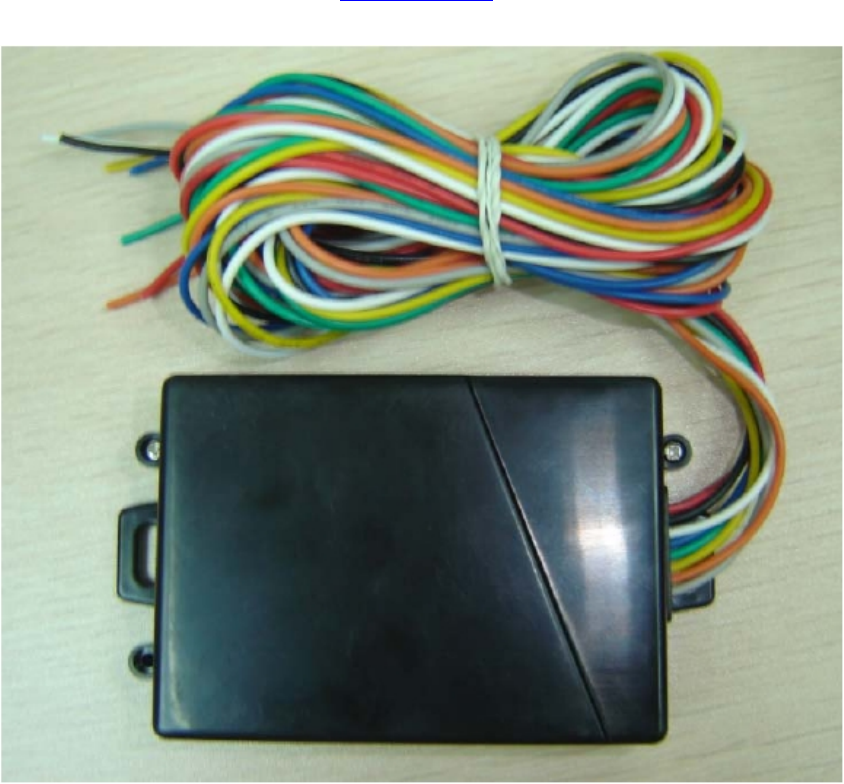
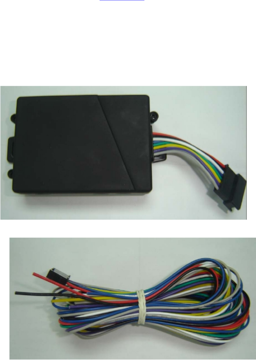
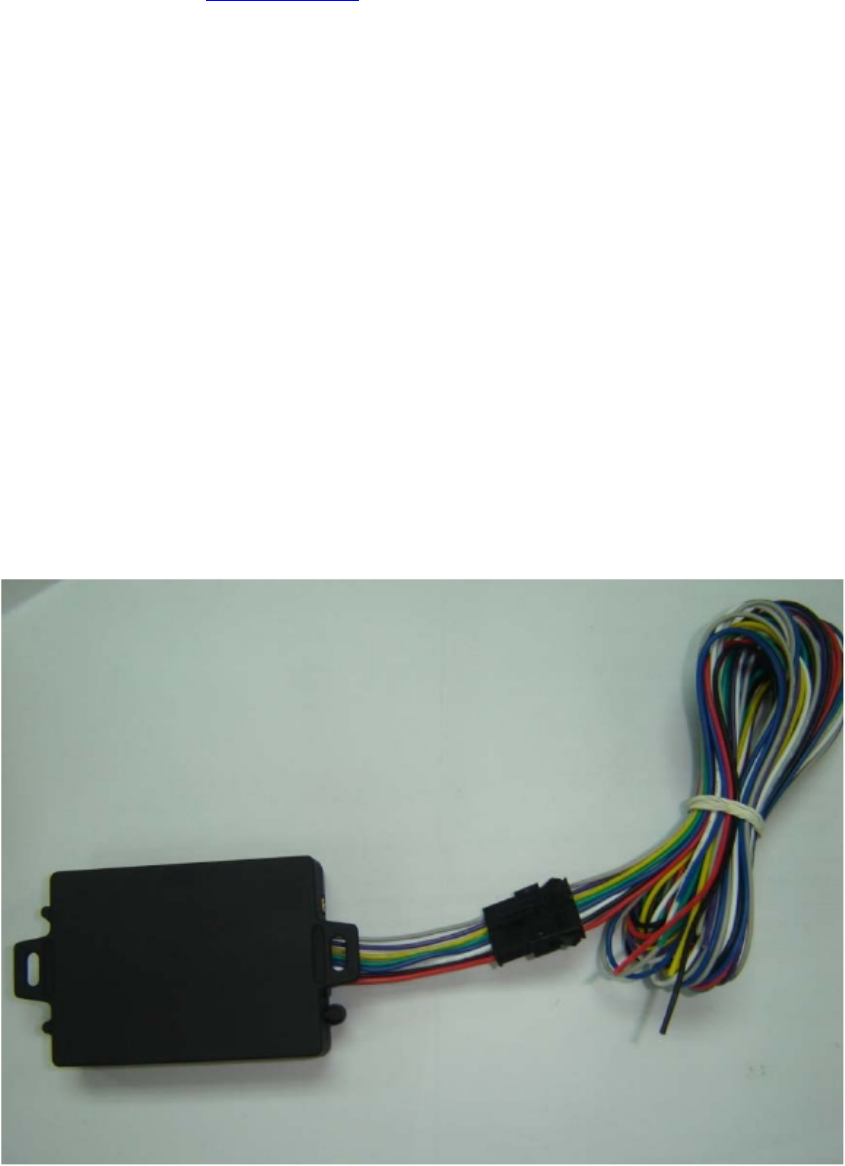
1. Product Parts List
AVL Unit
Car Charger Lighter Socket
Redview GPS
www.redview.net
- 9 -Page 9 of 30
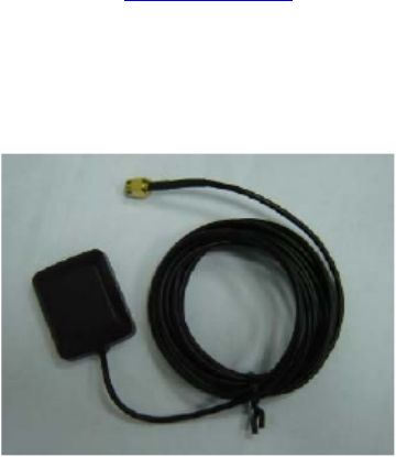
GPS Antenna(optional)
2. Precaution before Installation
Check if all the parts are included.
Prepare a SIM card for GSM communication. Use some other
mobile phone to confirm that the PIN code has not been set, and that
it can dial out and receive telephone calls without problem.

Redview GPS
www.redview.net
- 10 -Page 10 of 30
Before installing the SIM card, make sure to cut off power from the
AVL unit. The correct installation method is to push the tray
completely into the AVL unit, until you feel it is hooked by something.
Find a suitable place inside the car for installing the unit.
Check if all the wiring has been connected correctly; then connect
the AVL unit to the power source.
Redview GPS
www.redview.net
- 11 -Page 11 of 30
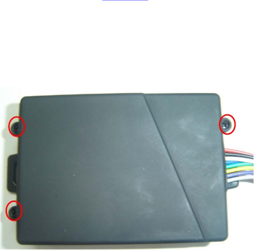
3.INSTALLATION
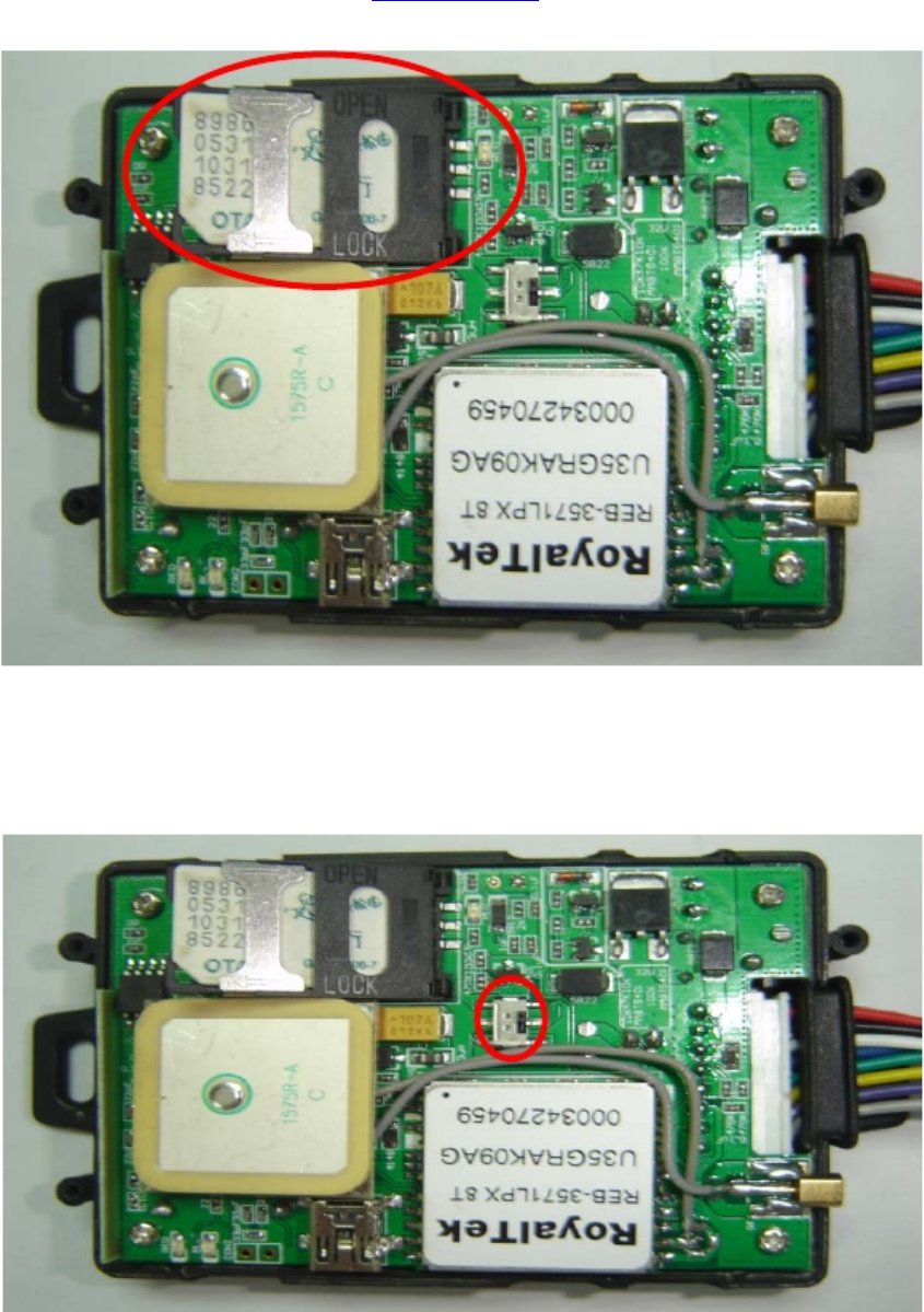
3.1 Step 1: Install SIM Card
(1) Unscrew and remove the front cover of your locator.
(2) Insert the SIM card by sliding it into the card holder slot, with the
chip module facing to the connectors on PCB, as direction shown in
the picture.
Redview GPS
www.redview.net
- 12 -Page 12 of 30
(3)Switch the tracker on ,as following picture shows.After switch
on,the red and blue led will blink
(4) Put back the front cover and screw it up.
Redview GPS
www.redview.net
- 13 -Page 13 of 30
※ Make sure to turn off the power before installing the SIM card.
※ Make sure to deactivate the PIN code, so that the SIM card can
operate without PIN protection.
※ Before install the SIM card to the GPS Tracker, please use a mobile
phone to make sure the SIM card can make & receive phone calls
without problem.
※ Before install the SIM card to the GPS Tracker, please use a mobile phone
to empty the SMS storage of the SIM card.
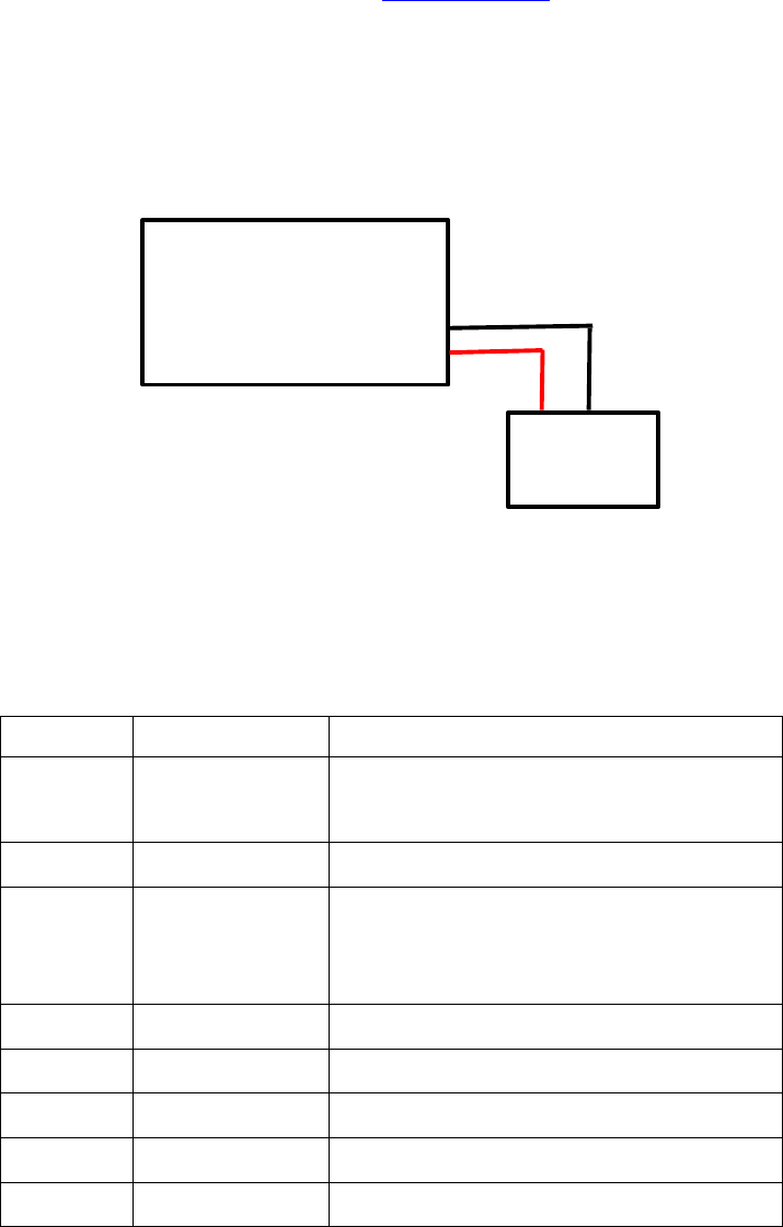
3.2 Step 2: Connect power charging
VT200 connects to the car charger lighter socket.
Pin Colour function
1 Red DC IN ( power input )
Input voltage : 9V~25V (important)
Suggested : 12V
2 Black GND
3 white No usage now
4 Blue No usage now
5 Green No usage now
6 Yellow No usage now
7 Purple No usage now
8 Gray No usage now
Redview GPS
www.redview.net
- 14 -Page 14 of 30
AVL
+ -
Car Battery
PIN description for VT200 socket:
Redview GPS
www.redview.net
- 15 -Page 15 of 30
4. Wiring Description
Connect the wiring correctly.
The AVL unit should be connected to power source, after all the
wiring work has been completed and checked.
Build-in GPS antenna and GSM antenna is used in this unit to make
installation easy.GPS antenna is used to receive satellite signals in the
sky. The front panel of this unit should be fixed to face the sky; and
should not be covered or shielded by any object containing metal,
such as the metallic windshield.
Front side
Wiring connections must be firm and reliable; and the joints should
be wrapped with insulating tape tightly.
The unused electrical wire should be properly insulated.
Redview GPS
www.redview.net
- 16 -Page 16 of 30
D. Operating Instructions
1. Position Report Function by SMS
No matter where you are, when you want to know the position of
your vehicle, send a SMS message or make a telephone call
to the VT200; it will report its location back to you by SMS .
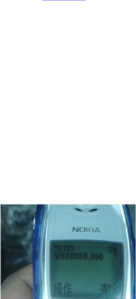
Edit a message as following format, then send it to VT200:
Format:
W+Password+, +000
( init password is : 000000)
For example:
W000000,000
The VT200 will send back one SMS ,which includes the position
information
Position Data means :

Feature Characteristics
GPS chipset SirF III
Power Supply +9V to +25V
Power Consumption For
VBATT
Active mode(peak) < 1.0A
Active mode(avg.) < 300mA
Idle mode < 50mA
Sleep mode < 5mA
Operating Temperature
Range
-20℃ to +60℃
Storage Temperature
Range
-20℃ to +70℃
Humidity Up to 75% non-codensing
External Antenna Connected via the 50Ω coax connector
External SIM Card Connected via SIM Card connector
SIM card type 3V
Redview GPS
www.redview.net
- 17 -Page 17 of 30
Longitude = 114 degree - 04 cent - 57.74 second
Latitude = 22 degree - 32 cent - 40.05 second
Tips:
Apply for one position service by another easier way:
(a) Make a cell phone call to VT200
(b) After listening the ring of VT200, wait for about 10s ,then you can
hold off the dialup --
(c) Then, after 10 second, the cell phone will receive
the Position SMS.
2. Tracking by GPRS
The VT200 can send GPRS package,with position info to preset IP
and port at preset time interval. For more about how VT200 sending
GPRS package,please refer to GPRS communication protocol.
E. Hardware Specifications

Transmit Power Class 4(2W) for E-GSM 900 and 850
Class 1(1W) for DCS 1800
Class 1(1W) for PCS 1900
Sensitivity -104 dBm minimum for E-GSM 900 and
850
-102 dBm minimum for DCS 1800
-102 dBm minimum for PCS 1900
Speech Codec Triple rate Codec:
Half rate –ETS 06.20
Full rate –ETS 06.10
Enhance Full rate-ETS 06.50/06.06/06.08
GPRS Multi-slot Class 8(4Rx , 1Tx , 5 slot Max.)
Support all 4 coding schemes(CS-1, CS-
2, CS-3 and CS-4)
● Maximum download speed is 85.6kbps
● Maximum upload speed is 21.4kbps
Circuit-Switched Data
Rate
14.4kbps
Interface Full duplex 3V CMOS-level Serial
interface for AT commands protocol
Dimensions 6.0 x 4.0 x 2.0 (cm)
Redview GPS
www.redview.net
- 18 -Page 18 of 30

SMS Instruction Format Note
1 Request one position W******,000
2 Modify user password W******,001,###### ****** is old password
###### is new password
3 Set the time interval to
position refresh W******,002,XXX XXX(3 digital)
=000,stop
=[1,999] time internal (unit: mins)
4 Set a preset phone number for
SOS button
When this button is pressed,
VT200 will dial the preset
number.
W******,003,1,1,TelNumber
TelNumber: Preset Tel number
(TelNumber must <16 digits )
5 Set low power alarm
When the VT200 voltage is
lower than the preset value,
VT200 will send one lower
power alarm SMS to the SOS
preset number.
W******,004,X X (voltage preset value)
=0 , close
=1, <3.3V send SMS alarm
=2 , <3.4V send SMS alarm
=3 , <3.5V send SMS alarm
(default )
=4 , <3.6V send SMS alarm
=5 , <3.7V send SMS alarm
5 Set over speed alarm
When the VT200 speed
higher than the preset value,
VT200 will send one over
speed alarm SMS to the SOS
preset number.
W******,005,XX XX (the speed preset value)
=00 , close
=[01<XX<20] (unit: 10Km)
6 Set Geo-fence alarm
When the VT200 move out
preset scope, VT200 will
send one Geo-fence SMS to
the SOS preset number.
W******,006,XX XX ( preset distance to original
place )
=00 close
=01 30m
=02 50m
=03 100m
=04 200m
=05 300m
=06 500m
Redview GPS
www.redview.net
- 19 -Page 19 of 30
G More Professional SMS Instruction
****** is user password , and init password is 000000

=07 1000m
=08 2000m
8 Extend setting
(note:
Please use this instruction
carefully)
W******,008,ABCDEFG### A=0 , Close position report function
which get position SMS
by Calling VT200
A=1 , Open position report function
which get position SMS
by Calling VT200
B=0, position SMS format be analyzed
in order to read easily.
For example:
Longitude = 114 degree - 04 cent - 57.74
second
Latitude = 22 degree - 32 cent - 40.05
second
B=1, position SMS format is NMEA
0183 Format
For example:
$GPRMC,072414.000,V,3114.3763,N,12131.325
5,E,0.00,0.00,050805,*00
C=0, VT200 do NOT hang up when one
call incoming .
C=1, VT200 hang up after 4~5 rings
when call incoming
D=0, VT200 do NOT send one notice
SMS to SOS preset number when
the GT30 power on
D=1, VT200 do send one notice SMS
to SOS preset number when the
GT30 power on
E=0, VT200 do NOT shut down
automatically when the power
voltage lower than 3V
E=1, VT200 will shut down
automatically when the power
voltage lower than 3V
F=0, VT200 do NOT send the notice
SMS to the SOS preset number
when the GPS signal is weak
F=1, VT200 send the notice SMS to
the SOS preset number when the
GPS signal is weak
###, end character
Redview GPS
www.redview.net
- 20 -Page 20 of 30

(Default value should be :
ABCDEFG=1011110 )
9 Set sleep mode for saving
power. W******,021,XX### XX=00 close sleep mode
XX=01 sleep
XX=02 deep sleep
GPRS setting
9 Set the phone number for
VT200 for GPRS W******,010,tel tel :
telephone number according the
SIM card of GT30
(tel must be < 14 digits)
10 Set APN W******,011,APN APN : APN string
11 Set IP Address &port number W******,012,IP,PORT IP: xxx.xxx.xxx.xxx
PORT: [1,65536]
12 Select GPRS protocol W******,013,X X=0 Enable Protocol B
( Suggestion )
X=1 Enable Protocol A
Redview GPS
www.redview.net
- 21 -Page 21 of 30

Redview GPS
www.redview.net
- 22 -Page 22 of 30
H GPRS communication setting
Step1: Make sure that your SIM card in VT200 support the GPRS function
Step2: Set tracker ID of VT200 by send one SMS:
SMS Format: W******,010, Tracker ID
For example :
W000000,010,123456
GT30 will response one SMS to confirm the setting.
For example : “Set SIM OK/123456”
( tip:
“123456” can be considered to be the device’s name. (Tracker ID must be < 14 digits)
If there are several devices ,you can use their Tracker ID to differ from each other. )
Step3 : Set IP address and Port by send one SMS
SMS Format: W******,012,IP,PORT
IP: xxx.xxx.xxx.xxx
PORT: [1,65536]
For example :
W000000,012,202.116.11.12,8000
GT30 will response one SMS to check it.
Like “Set IP ok /202.116.11.12#8000”
( tip:
Make sure that the IP should be the Extranet IP. If your pc is in Intranet ,you must know your
Extranet IP . You may need the help of you network administrator )

Redview GPS
www.redview.net
- 23 -Page 23 of 30
Step4: Set APN String
SMS format : W*****,011, APNString
For example :
W000000,011, CMNET
GT30 will response one SMS to check it
For Example “set APN OK /CMNET”
Step5: Set time interval of sending GPRS package
SMS format: W******,014 , XXXXX
XXXXX:means times interval, (Unit: 10s)
( The length of XXXXX MUST be 5 digits )
XXXXX=00001, means time interval is 10s;
XXXXX=00000, means STOP GPRS function.
For example:
W000000,014,00003
SMS meaning: Make GT30 send a GPRS package every 30 seconds
GT30 will response one SMS to confirm the setting .
For example “set GPRS Timer ok/00003”
( tip:
W000000,014,00000 mean STOP GPRS function )
Step6: Enable communication protocol type
SMS format: W******,013,X
X meaning is defined by RedView GPS.
You can set it as 1 or 0
X=0: Enable Protocol B ( Suggestion )
X=1: Enable Protocol A
For example: W00000, 013, 1
W00000, 013, 0
Redview GPS
www.redview.net
- 24 -Page 24 of 30
(tip: About the detail of Protocol B or Protocol A
pls contact with our support teams: customer@redview.net )
Step7 : According to the document of our RedView GTP communication protocols , the
server can analyses the GPRS data.
Please contact us if you have not this protocol :
customer@redview.net
(tips:
1 You can get the latitude & longitude data sent from GT30 by GPRS every interval
time from the Any software of TCP receiver ,which is installed in your PC.
2 if you require the document about GTP communication protocol of GT30, please
contact us by mail. Our mail address: annagps@gmail.com )
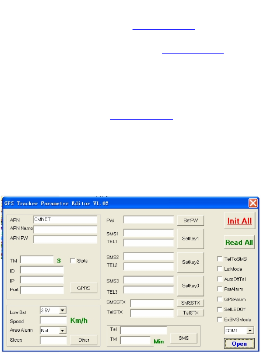
3 for bulk number:
You can configure VT200 by PC tools named “Parameter Editor” in CD
----the tools is be designed by RedView GPS, and it is for configuring bulk number of
Tracker unit, And the customers require one special USB configure cable from RedView
GPS which connect PC with Tracker unit.
For detail, read RedView Configuration tool V1.02 User Guide in CD

Redview GPS
www.redview.net
- 25 -Page 25 of 30
K Trouble shooting
If you find some trouble in using VT200, please refer the following:
(1) Check GPS signal is normal,
please check following issue:
(a) Working outdoor,VT200 can get better GPS signal;
(b) Check the front side is placed toward sky;
(c ) Charging VT200 for 3 hours for the tracker has enough power before usage
(2) Check GSM signal is normal
(a) Whether the GSM network is strong enough to make the track unit work.
You can judge it by calling someone thorough your cell phone.
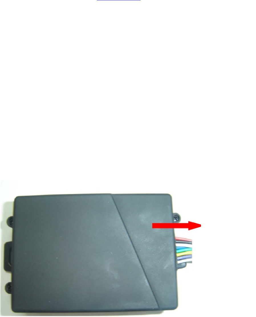
(b) Whether the SIM card is installed correctly or not ,and try to pull out and insert
SIM card as following picture shows to ensure it; try this operation a few times
may help to ensure correct installation
(c) Whether there is enough deposit in SIM card or not;
(d) Whether your SIM card in VT200 support SMS function or not, (including send
SMS and receive SMS)
(f) Whether SIM card has specific requirement on cell phone or not,
for example whether the SIM card can only use in a appointed cell phone, other
cell phone cannot use the SIM card
(g) Whether SIM card is binding to the specific cell phone or not
(h) Whether SIM card need some authorization when using it
For example, you need type one password when you use the kind of SIM cards
(i) Whether the tracker has enough power to work, we strongly suggest it was
charged at least 3 hours before use it
(3) The SMS which be replied by VT200 is including the chars --- “ Last ……….”
It is indicate the GPS signal is weak.
Redview GPS
www.redview.net
- 26 -Page 26 of 30
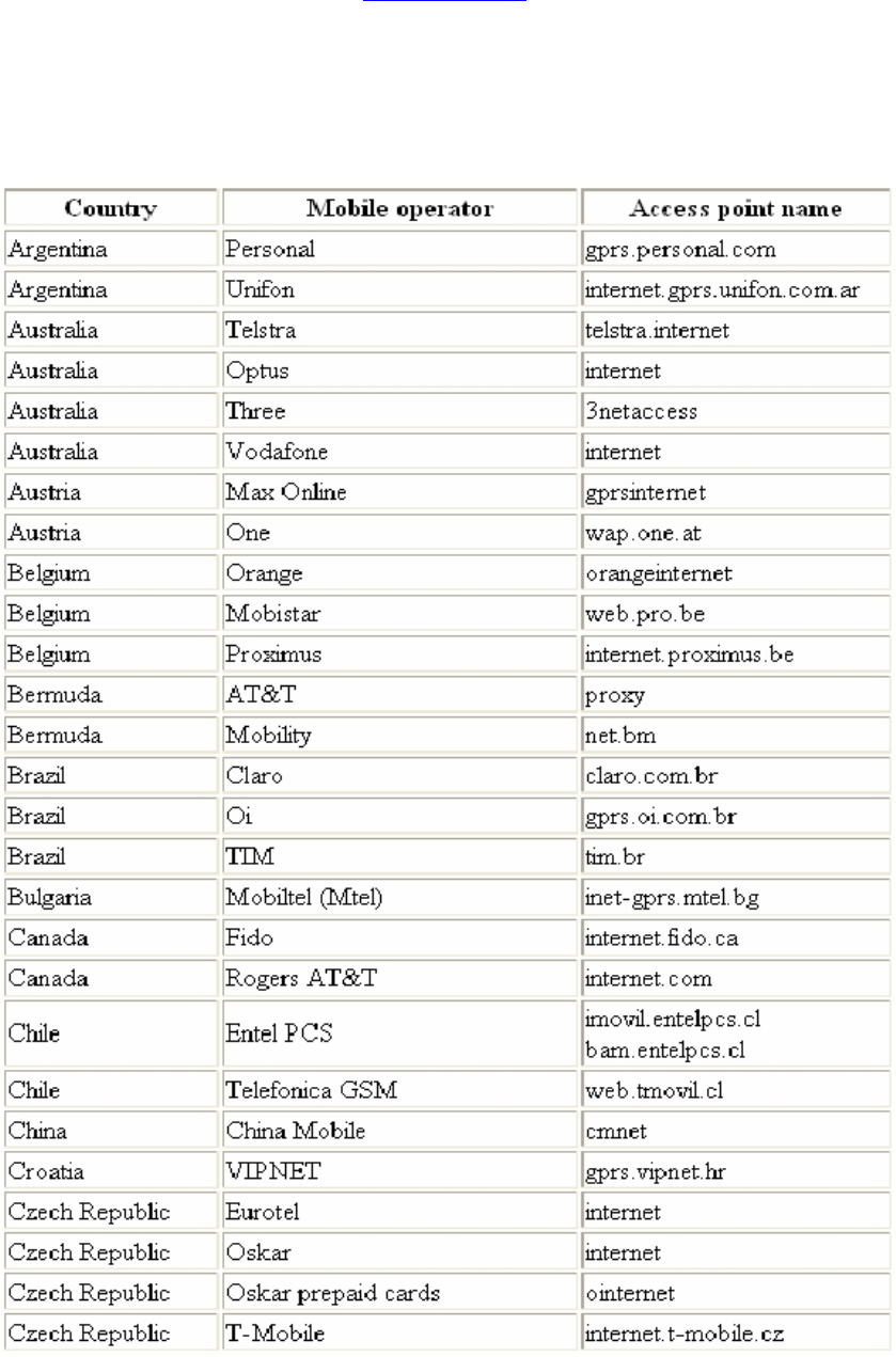
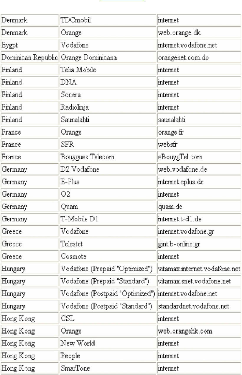
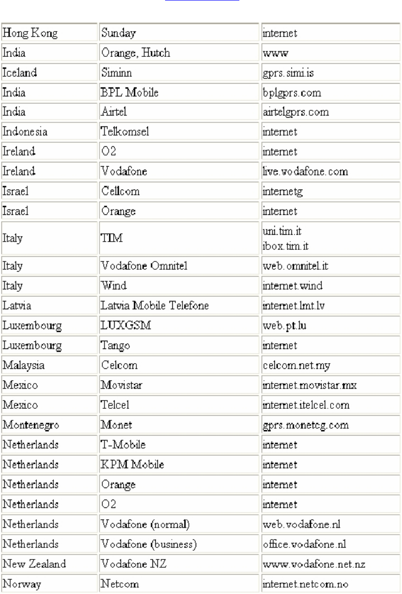
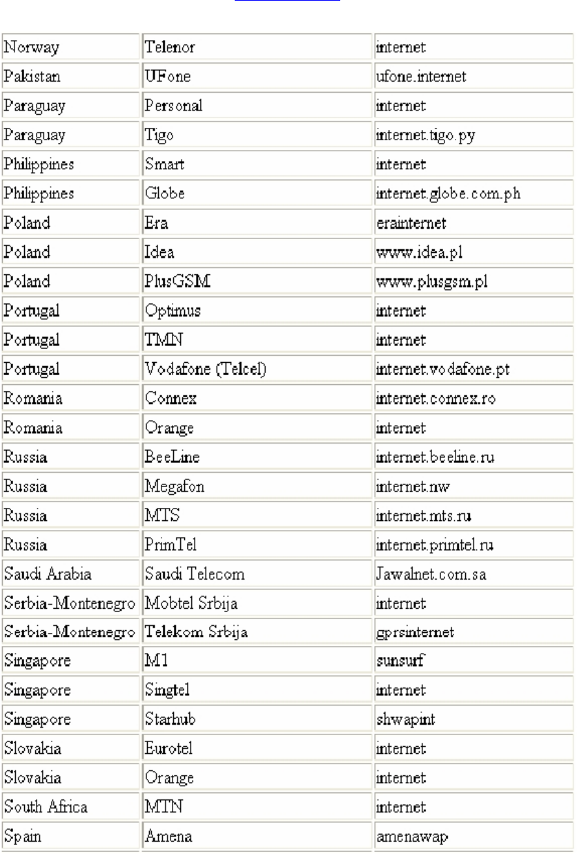
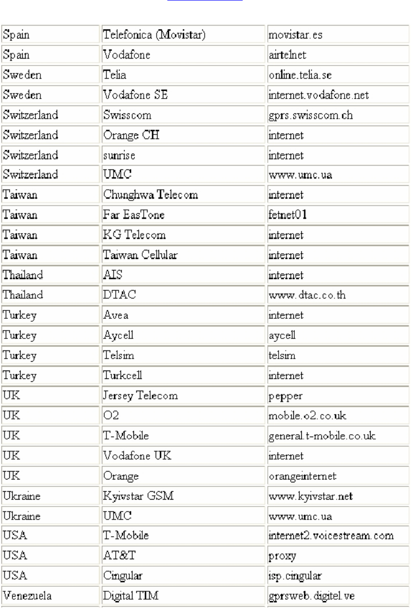
Attachment :Worldwide APN (Access
Point Name) List
Redview GPS
www.redview.net
- 27 -Page 27 of 30
Redview GPS
www.redview.net
- 28 -Page 28 of 30
Redview GPS
www.redview.net
- 29 -Page 29 of 30
Redview GPS
www.redview.net
- 30 -Page 30 of 30
FCC RF Radiation Exposure Statement
This equipment complies with FCC RF radiation exposure limits set forth for an uncontrolled
environment. This device and its antenna must not be co-located or operating in conjunction
with any other antenna or transmitter.
“To comply with FCC RF exposure compliance requirements, this grant is applicable to only
Mobile Configurations. The antennas used for this transmitter must be installed to provide a
separation distance of at least 20 cm from all persons and must not be co-located or
operating in conjunction with any other antenna or transmitter.”