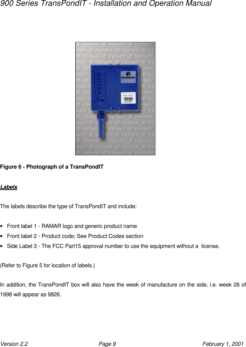
Blue Tower Communications TRANSPONDITV4 Utility Meter Reader User Manual User Instructions

Blue Tower Communications Ltd Utility Meter Reader User Instructions

user manual

      AT RAMAR LLC ••  P.O. Box 110127  ••  Research Triangle Park  ••  North Carolina  ••  27709 (919) 991-9924 ••  Fax (919) 991-9946 www.ramartech.com TransPondIT      Installation and Operation Installation and Operation ManualManual  Version 2.2 Updated February 1, 2001
900 Series TransPondIT - Installation and Operation Manual Version 2.2 Page 2 February 1, 2001   Contents Introduction ....................................................................………………………. 3 System Overview ..................................................................................……… 4 Getting Started .....................................................................…………............. 7 Hardware Description ...........................................................................….….. 8 Physical Characteristics ......................................…………………….….. 8 Labels ............................................………………………………….…….. 9 Cable Types ...............................……………………………………….….. 10 Cable Lengths ...............................………………………………………... 10 Restraining Nut .......................................................………………….…. 11 Product Codes .....................................................................…………………… 12 Detailed Description of TransPondIT Variants ......................................….… 13 TT915/F-01 Single Pulse ………….........................................….…....…. 13 TT915/F-02 Master Meter Dual Pulse .........................…..………..…...… 13 TT915/F-03 ABB Scancoder..................................………......….…....…. 13 TT915/F-04 Sensus ECR.........................................……..………..…...… 14 TT915/F-05 Schlumberger ARB V...........................…............….…....…. 15 TT915/F-06 Schlumberger ProRead........................….…..………..…...… 15 TT915/F-07 Pulse Generator.........................................……………....…. 16 Installation Procedure ........……………………………………...............………… 17 Equipment Required for TransPondIT Installation ………………………… 17 Wall Mounted TransPondIT …………………............................………….. 18 Pipe Mounted TransPondIT …………………..................……………….… 20 Pit Mounted TransPondIT …………………..................………………….... 22 Wiring Instructions for TransPondIT .........................................……..…....…. 24 Water Meter Connection Chart ………………………………………..……. 24 Troubleshooting …………………………………………………………………….. 25
900 Series TransPondIT - Installation and Operation Manual Version 2.2 Page 3 February 1, 2001  Introduction  Utility meters were traditionally read by eye, with the data being manually keyed into a hand-held computer or written down on a clipboard carried by the meter reading personnel.  RAMAR has developed its 900 Series remote meter reading (RMR) system to read utility meters via radio frequency (RF) using the 902-928 MHz Industrial, Scientific & Measurement (ISM) band.  In RAMAR’s RMR system, the utility meters are equipped with a radio - based meter interface unit (MIU) called the TransPondIT.  The TransPondIT transmits meter reading data to a variety of different receiving devices, which may be mobile or fixed.  For example, a pedestrian meter reader may be equipped with a hand-held computer and a TransPondIT reading device called the HandTrackIT and a vehicle-based meter reader may be equipped with a device called a FastTrackIT.  A permanent sub-metering system may collect the data into a fixed device called a CellTrackIT.  This document provides installation and operation  instructions for the 900 Series TransPondIT.  Refer to the ConFigIT and HandTrackIT operating manuals for more detailed information about the configuration and operation of other 900 Series products.   NOTE:  The user is cautioned that changes or modifications not expressly approved by the party responsible for compliance could void the user’s authority to operate the equipment.
900 Series TransPondIT - Installation and Operation Manual Version 2.2 Page 4 February 1, 2001  System Overview  The TransPondIT is a radio unit that can be connected to a variety of water meters.  A TransPondIT collects the consumption data from the water meter via a connecting cable and stores the data inside the TransPondIT.  The TransPondIT then periodically transmits that data to a range of receiving devices - HandTrackIT, FastTrackIT and CellTrackIT.   Figure 1 - A TransPondIT connected to a water meter  The receiving devices store and send the meter reading data to a number of systems that can process and record that data.  For example, the HandTrackIT will normally send the data onto a hand-held computer from where it will ultimately go into a utility’s billing system.  A vehicular-based system may send the data to a laptop PC in the meter readers vehicle where it will be uploaded into a billing system at the end of the day.  A stationary fixed receiver may be connected to a modem, and the host billing system will dial in, via that modem, to collect the data.
900 Series TransPondIT - Installation and Operation Manual Version 2.2 Page 5 February 1, 2001   Figure 2 - A HandTrackIT connected to a hand held computer   TransPondITs can interface to a wide range of utility meters.  However, before they can be read, TransPondITs need to be configured to ensure that:  • The TransPondIT is switched on and transmitting;  • The TransPondIT is configured/set-up to interface to the particular water meter to which it is connected.  This configuration process is accomplished by a unit called the ConFigIT.  The ConFigIT is connected to a laptop PC (Windows 95, Windows 98, or Windows NT) which allows the user to switch on/off the TransPondIT and configure the TransPondIT for its particular utility meter.  See Figure 3 and Figure 4.
900 Series TransPondIT - Installation and Operation Manual Version 2.2 Page 6 February 1, 2001             Figure 3 - A TransPondIT being configured in a ConFigIT (The TransPondIT is inserted into the ConFigIT housing which then switches the transmitter on/off and configures the TransPondIT to interface to a particular meter type)  The ConFigIT is connected to a laptop PC and allows the user to select various parameters of the TransPondIT, e.g. the meter type, serial number, etc.  See  ConFigIT Installation and Operating Instructions.            Figure 4 - A ConFigIT connected to a laptop PC (The ConFigIT is powered by four AA cell batteries and connected to the laptop via a RAMAR cable <Product number: HNDOPC03>)  RS-232 is a 9 Pin Male DB9 Connector on the computer
900 Series TransPondIT - Installation and Operation Manual Version 2.2 Page 7 February 1, 2001  Getting Started    The 900 Series TransPondIT is shipped from the factory with the transmitter switched off.  Before attempting to do a reading of the TransPondIT, the transmitter must be enabled by the ConFigIT.  Please refer to the ConFigIT Installation and Operating instructions for detailed instructions.  The 900 Series TransPondIT is shipped from the factory programmed for a specific meter type.  Therefore, one TransPondIT will not communicate with all meters, and different TransPondIT model numbers have to be ordered for each type of water meter.  Please refer to the product codes table in this document.  It is important that  THE CORRECT TRANSPONDIT IS CONNECTED TO  THE WATER METER, otherwise the TransPondIT will not return a valid reading.  The TransPondIT has a restraining nut clamping the cable from the water meter at the point where it enters the TransPondIT’s body.  This has been tightened and sealed to ensure a waterproof product.  DO NOT LOOSEN THE NUT, OR THIS WILL INVALIDATE THE WATERPROOF RATING OF THE PRODUCT.  The TransPondIT will operate in a basement, underground water pit and other hostile environments provided it is correctly installed.  The TransPondIT may have a variety of different wire-ended or moulded cables attached to it to connect it to the different types of meters.  The wire-ended TransPondIT requires specific installation techniques to maintain the waterproof rating.  PLEASE CONSULT THE INSTALLATION INSTRUCTIONS IN THIS MANUAL TO INSTALL THE TRANSPONDIT IN WATER METER PITS OR OTHER WET ENVIRONMENTS.
900 Series TransPondIT - Installation and Operation Manual Version 2.2 Page 8 February 1, 2001  Hardware Description  The TransPondIT is a battery operated AMR unit completely sealed in a plastic housing.  The product has a lifetime of ten years and will connect to a wide range of water meters.  Physical Characteristics  The plastic square box casing containing the TransPondIT is approximately 3¼” x 3¼” x 1” (80mm x 80mm x 25mm).  Two ‘shoulders’ located on the top and bottom sides are provided, between which a tie-wrap, or strap, can be placed for securing the TransPondIT into position in a pit.  The entire assembled product weighs approximately 3.8oz (110g) excluding pit fixing attachments and strap.                                TOP         Figure 5 - Front Upright View of a TransPondIT Front Label 1 Front Label 2 Restraining Nut Cable Side Label 3
900 Series TransPondIT - Installation and Operation Manual Version 2.2 Page 9 February 1, 2001                 Figure 6 - Photograph of a TransPondIT  Labels  The labels describe the type of TransPondIT and include:  • Front label 1 - RAMAR logo and generic product name • Front label 2 - Product code; See Product Codes section • Side Label 3 - The FCC Part15 approval number to use the equipment without a  license.  (Refer to Figure 5 for location of labels.)  In addition, the TransPondIT box will also have the week of manufacture on the side, i.e. week 26 of 1998 will appear as 9826.
900 Series TransPondIT - Installation and Operation Manual Version 2.2 Page 10 February 1, 2001   Cable Connection to Meters  A standard TransPondIT will come fitted with a 1-meter length of cable.  This cable will be terminated in a number of ways depending on the type of water meter to which the TransPondIT is being connected.  There are several ways a cable can be connected to a meter:  • Wire ended cable from the TransPondIT is attached to meter register screw terminals and potted (a water-resistant resin) into the head of the meter for water pit applications. • Wire ended cable from the TransPondIT is spliced into an existing cable from the water meter and inserted into a direct burial connector for water pit applications. • Wire ended cable from the TransPondIT is attached to meter register screw terminals and not potted for indoor applications such as basements. • Wire ended cable from the TransPondIT is spliced to an existing cable from the water meter for indoor applications such as basements. (May include cable extension wire) • A “probe” ended cable from the TransPondIT containing a reed switch, or other sensor, is inserted into an opening in the meter.   Cable Lengths  • For pulse output meters, the maximum recommended cable length is 250 ft.  • For encoded meters, the maximum recommended cable length is 50 ft.  (In order to determine the type of meter to connect to the TransPondIT, please refer to the section of this manual, referenced “Product Codes”).
900 Series TransPondIT - Installation and Operation Manual Version 2.2 Page 11 February 1, 2001   Restraining Nut   This nut seals the cable to the TransPondIT to ensure that the TransPondIT is waterproof.  It must never be loosened.  The nut is tightened and glued during manufacture to a specified torque, and tampering with this nut will void the warranty and destroy the waterproof seal.  There are no user serviceable parts inside.
900 Series TransPondIT - Installation and Operation Manual Version 2.2 Page 12 February 1, 2001  Product codes  The product codes are listed below:   Product Specification Product Information TT-915/F-01 Single Pulse (ABB Pulser, Badger RTR, Metron Farnier, reed switches, etc.) TT-915/F-02 Master Meter Dual Pulse TT-915/F-03 ABB Scancoder TT-915/F-04 Sensus ECR Protocol TT-915/F-05 Schlumberger ARB V TT-915/F-06 Schlumberger ARB ProRead TT-915/F-07 Pulse Generator Type Meter Register TT-915/F-08 Not Assigned
900 Series TransPondIT - Installation and Operation Manual Version 2.2 Page 13 February 1, 2001  Detailed Description of TransPondIT Variants  TT915/F-01 This TransPondIT will connect to many types of pulse output water meter, including the Badger Meter’s Piezo switch meter (the RTR index).  This TransPondIT can be interfaced to the Hersey ER-1 utilizing a specially designed probe.  The TransPondIT can be configured at installation using the ConFigIT to its reading to match the meter reading to the dial of the water meter.  Furthermore many water meters provide “x” number of pulses per unit of water passed, and a “pre-scaling/x” factor can then be selected in the TransPondIT, so that the reading on the index will correspond to the meter reading in the TransPondIT.  Finally, the Customer/Utility code and the TransPondIT ID can be selected at the ConFigIT stage.  For convenience the ID number of the TransPondIT can be made to be that on the water meter, or any other unique ID number selected by the utility up to a maximum of 16,777,215.  TT915/F-02 This TransPondIT is similar to the TT915/F-01, but it will monitor two pulse switches on the water meter, rather than just one.  The advantage of this method is that only water passing in one direction will be recorded.  The TransPondIT will recognise the direction of flow, and not account for small water amounts flowing backwards through the meter.   In a single pulse output meter, “backflow” could cause the reed switch to operate and the TransPondIT to record consumption.  TT915/F-03 This TransPondIT will read the ABB Scancoder register.  On configuration, the TransPondIT will read the ABB Scancoder register using the ABB protocol, and the TransPondIT will transmit the absolute meter reading as it appears on the water meter dial.  The
900 Series TransPondIT - Installation and Operation Manual Version 2.2 Page 14 February 1, 2001  Customer/Utility code and the ID number have to be entered at the ConFigIT stage as before.  The ID number may be the unique utility serial number of the water meter.  The TransPondIT will “refresh” its meter reading from the ABB Scancoder every one-hour or more; this interval is configurable at the ConFigIT stage.  However any interval less than one hour will have an adverse effect on battery life.  All TransPondITs will immediately collect a reading from the ABB Scancoder on configuration by the ConFigIT, so that the match between the ABB Scancoder index and the TransPondIT reading can be verified at that time, rather than after the “refresh” interval.  TT915/F-04 This TransPondIT will read the Sensus ECR protocol.  On configuration, the TransPondIT will read the Sensus water meters (SR, SR II) using the Sensus protocol (both fixed and variable length), and the TransPondIT will transmit the absolute meter reading as it appears on the water meter dial.  The Customer/Utility code has to be entered at the ConFigIT stage as before.    However the Sensus meter ID number is “passed through” to the TransPondIT and becomes the TransPondIT ID, overwriting any ID set at the ConFigIT stage.  The TransPondIT will “refresh” its meter reading from the Sensus index once an hour or more; this interval is configurable using  ConFigIT.  However, setting the refresh interval rate to less than one hour will have an adverse effect on battery life.  The TransPondIT will immediately collect a reading from the ECR index on configuration by the ConFigIT, so that  the match between the meter index and the TransPondIT reading can be verified immediately.
900 Series TransPondIT - Installation and Operation Manual Version 2.2 Page 15 February 1, 2001  TT915/F-05 This TransPondIT will read the Schlumberger ARB V register type.  On configuration, the TransPondIT will read the Schlumberger  water meters using the Schlumberger ARB V protocol, and the TransPondIT will transmit the absolute meter reading as appears on the water meter dial.  The Customer/Utility code has to be entered at the ConFigIT stage as before.    The Schlumberger ARB V register does not have its own ID number embedded in its index.  The ID number will therefore need to be entered into the TransPondIT at the configuration stage.  The TransPondIT will “refresh” its meter reading from the Schlumberger ARB V at least once an hour or more; this interval is configurable by the ConFigIT.  However any interval less than one hour will have an adverse effect on battery life.  The TransPondITs will immediately collect a reading from the Schlumberger ARB V index on configuration by the ConFigIT, so that the match between the Schlumberger ARB V index and the TransPondIT reading can be verified immediately.  TT915/F-06 This TransPondIT will read the Schlumberger Pro Read water meter index.  On configuration, the TransPondIT will read the Schlumberger Pro Read index using  Schlumberger ARB protocol, and the TransPondIT will transmit the absolute meter reading as appears on the water meter dial.  The Customer/Utility code has to be entered at the ConFigIT stage as before.    The Schlumberger Pro Read index has a programmable ID number in its index, this is “passed through” to the TransPondIT.  The TransPondIT ID number will not need to be input into the TransPondIT at the ConFigIT stage. (Note: the TransPondIT ID number is limited to an eight digit number, which may affect the number returned by certain index types, including the Schlumberger ProRead)
900 Series TransPondIT - Installation and Operation Manual Version 2.2 Page 16 February 1, 2001  The TransPondIT will “refresh” its meter reading from the Schlumberger Pro Read index once an hour or more; this interval is configurable by the ConFigIT.  However any interval less than one hour will have an adverse effect on battery life.  The TransPondITs will immediately collect a reading from the Schlumberger Pro Read index upon configuration by the ConFigIT, so that the match between the Schlumberger Pro Read index and the TransPondIT reading can be verified immediately.  TT915/F-07 This TransPondIT will read the generator type outputs from several different manufacturers.  The TransPondIT is configured like a type –01 TransPondIT.  The starting meter reading is programmed into the TransPondIT and the appropriate pre-scale is selected to provide a TransPondIT reading that matches the meter index. The Customer/Utility code has to be entered at the ConFigIT stage as before.    Step by step TransPondIT installation procedures are given in the following pages.
900 Series TransPondIT - Installation and Operation Manual Version 2.2 Page 17 February 1, 2001  Installation Procedure  Equipment Required for TransPondIT Installation  The following equipment is required for TransPondIT installation:  • A programmed  and configured TransPondIT (the ConFigIT stage can be completed after the meter has been connected to the TransPondIT, but it must be before the TransPondIT has been mounted in position.) • Hellermann Insuloid LOK01B Fixing pin / Hellermann Insuloid LOK350 tie-wrap or double-sided tape for fixing the TransPondIT in position (or equivalent mounting hardware) or Mounting Bracket Specifically Designed for RAMAR • Drill and  0.25” drill-bit suitable for drilling into the wall material expected (such as concrete), if required • Small hammer • Mounting Bracket Specifically Designed for RAMAR
900 Series TransPondIT - Installation and Operation Manual Version 2.2 Page 18 February 1, 2001  Wall-mounted TransPondIT  Attach the probe assembly to the metering device or, in the case of the wire-terminated unit, connect the wires to the existing cable and seal the joint to prevent ingress of moisture (glue-filled or jelly-filled splicing materials are recommended).  If outdoors, a Direct Burial Connector must be used, or the wire-end must be potted into the meter using an epoxy type sealing and potting compound.  Configure the TransPondIT with: • Customer/utility code • ID number if it is not “passed through” from an encoded index • Current meter reading if the meter is a pulse output meter • Pre-Scaling/x factor if the meter is a pulse output meter • Meter type • Transmission Interval • Meter reading interval if the meter is an encoded meter • Tamper count if the meter is a pulse output meter  (In order to define the type of meter to connect to the TransPondIT, please refer to the section of this manual, referenced “Product Codes”).  Mount the TransPondIT as high above the ground as possible, orientated with the cable entry underneath (See Figure 7).  TransPondIT should be at least 4” from any large metal surfaces (water tanks or foil-covered plasterboard). The radio range will be impaired if such an object, close to the TransPondIT, is between the TransPondIT and the reader.  Drill a 0.25” diameter hole in the wall/surface to which the TransPondIT will be attached, approximately 1” above the intended centre of the TransPondIT case, and tap the plastic plug (LOK01B) into the hole with the hammer.  Attach the TransPondIT case to the plastic plug using the LOK350 tie-wrap or use double-sided tape to stick the TransPondIT into place.
900 Series TransPondIT - Installation and Operation Manual Version 2.2 Page 19 February 1, 2001  Brackets designed especially for the TransPondIT may be available from your RAMAR distributor.  Please check for availability and pricing.  Perform a radio-read with a HandTrackIT and a visual-read in order to check that the information received is correct.  If possible, repeat last step after some meter activity to confirm correct metering activity and configuration of the Meter Interface.  NOTE: Under no circumstances should a metal clamp or bracket be used to secure the TransPondIT enclosure.  Try also to avoid pipe-mounting TransPondIT as often as possible.  Poor radio performance may result.  If it is necessary to use some clamp or bracket fixing other than that recommended by RAMAR, it is strongly recommended that  RAMAR be consulted and plastic fittings be used.     Figure 7- Wall-mounted TransPondIT using double-sided adhesive pad
900 Series TransPondIT - Installation and Operation Manual Version 2.2 Page 20 February 1, 2001  Pipe-mounted TransPondIT  Attach the probe assembly to the metering device or, in the case of the wire-terminated unit, connect the wires to the pulser mechanism and seal the joint to prevent ingress of moisture (glue-filled or jelly-filled jointing materials are recommended).  If outdoors, a Direct Burial Connector must be used, or the wire-end must be potted into the meter.  Configure the TransPondIT with: • Customer/utility code • ID number if it is not “passed through” from an encoded index • Current meter reading if the meter is a pulse output meter • Scaling/x factor if the meter is a pulse output meter • Meter type • Transmission Interval • Meter reading interval if the meter is an encoded meter • Tamper count if the meter is a pulse output meter  (In order to define the type of meter to connect to the TransPondIT, please refer to the section of this manual, referenced “Product Codes”).  Should no other method be available for mounting the TransPondIT to the meter, mount the TransPondIT unit as high as possible,  orientated with the cable entry underneath, preferably on a horizontal section of pipe, away from other pipes and at least 4” (100mm) from any large metal surfaces.  Attach the TransPondIT case to the pipe using the LOK350 tie-wrap, so the pipe passes behind the centre of the TransPondIT body (See Figure 8).  Perform a radio-read with a HandTrackIT and a visual-read in order to check that the information received is correct.
900 Series TransPondIT - Installation and Operation Manual Version 2.2 Page 21 February 1, 2001  If possible, repeat last step after some meter activity to confirm correct metering activity and configuration of the Meter Interface.      Figure 8 - Pipe-mounted TransPondIT
900 Series TransPondIT - Installation and Operation Manual Version 2.2 Page 22 February 1, 2001  Pit-mounted TransPondIT   For a pit-mounted TransPondIT, the TransPondIT will either:  • Come potted into the meter, or • Be connected via a water proof direct burial connector or • Come with a reed switch probe moulded onto the cable for inserting into the meter.  It is feasible to apply an epoxy-potting compound in the field to “pot” the TransPondIT wire-end into the head of the meter.  However this is not advisable, and the above options are preferred.   If it is not a new installation and the meter is not available already potted with the TransPondIT, attach the probe assembly to the metering device or, in the case of the wire-terminated unit, a Direct Burial Connector must be used.  Configure the TransPondIT with: • Customer/utility code • ID number if it is not “passed through” from an encoded index • Current meter reading if the meter is a pulse output meter • Scaling/x factor if the meter is a pulse output meter • Meter type • Transmission Interval • Meter reading interval if the meter is an encoded meter • Tamper count if the meter is a pulse output meter  (In order to define the type of meter to connect to the TransPondIT, please refer to the section of this manual, referenced “Product Codes”).  Mount the RAMAR unit as high as possible but without causing damage to the frost-protection material (if present), orientated with the cable entry underneath (See Figure 9).
900 Series TransPondIT - Installation and Operation Manual Version 2.2 Page 23 February 1, 2001  Drill a 0.25” diameter (6mm) hole in the wall/surface to which the TransPondIT will be attached, approximately 1” (25mm) above the centre of the TransPondIT case and tap the plastic plug (LOK01B) into the hole with the hammer.  Attach the TransPondIT case to the plastic plug using the LOK350 tie-wrap.  Perform a radio-read with a HandTrackIT and a visual-read in order to check that the information received is correct.  If possible, repeat last step after some meter activity to confirm correct metering activity and configuration of the Meter Interface.     Figure 9 - Pit-mounted TransPondIT
900 Series TransPondIT - Installation and Operation Manual Version 2.2 Page 24 February 1, 2001  Wiring Instructions for TransPondIT   One TransPondIT is connected to one meter; the wiring of the TransPondIT is as follows:  • GREEN wire to be connected to Pulse 1 Output or Meter Clock/Power • BLUE wire to be connected to Tamper/Pulse 2 Output or Meter Data • SHIELD wire to be connected to Ground   Water Meter Connection Chart Error! Not a valid link. To determine the correct TransPondIT and wiring connections:  1. Find the type of meter to be connected on the left side of the chart. 2. Go across to the fourth column and read the model of TransPondIT. 3. Look across to the right for wiring connections. The TransPondIT wire color code is listed across the top of the chart 4. Connect the wires as indicated on the chart.  Note: Please contact RAMAR for further details on meter compatibility and connections.   Troubleshooting  Replace all Batteries prior to performing these troubleshooting steps.  The following information will allow the installer or meter technician to determine why the TransPondIT signal is not being read.  By sequentially eliminating each piece of equipment, the meter technician can determine the cause of the problem.  The following is the procedure for troubleshooting the RAMAR system.  Equipment required:  TransPondIT HandTrackIT w/ Cable HNDOPC02
900 Series TransPondIT - Installation and Operation Manual Version 2.2 Page 25 February 1, 2001  HandTrackIT Installation and Operating Instructions ConFigIT w/ Cable HNDOPC03 ConFigIT Installation and Operating Instructions Hand Held Computer  Lap top Computer (Required to isolate hand held from system) 9-Volt Battery or power supply  1. Disconnect the HandTrackIT from the hand held computer. 2. Connect the HandTrackIT to the lap top computer using cable number HNDOPC02. 3. Start the HyperTerminal program and enter the UD Monitor Mode (refer to the HandTrackIT Installation and Operating Instructions for detailed procedure to set-up the HandTrackIT in the monitor mode.) 4. Press the <Enter> key to obtain the HandTrackIT prompt.  (If no prompt is obtained, refer to the HandTrackIT Installation and Operating Instructions for troubleshooting procedures for the HandTrackIT) 5. Position the HandTrackIT within the range of the TransPondIT under test to observe the signal from the TransPondIT.
900 Series TransPondIT - Installation and Operation Manual Version 2.2 Page 26 February 1, 2001  6. Monitor the TransPondIT signal for correct utility code, identification number, and meter reading: • If the TransPondIT signal is OK, then check the TransPondIT ID # and utility code in the hand held configuration file. • If the TransPondIT signal is not present, place the TransPondIT in the ConFigIT (Refer to the  ConFigIT Installation and Operating Instructions) and “Read” the TransPondIT configuration parameters.  (Ensure the transmitter is enabled and the correct utility code, TransPondIT ID #, and meter information has been set.) 7. If the TransPondIT cannot be read by the ConFigIT, replace it with a known good unit and retest. 8. Reconnect the Handheld computer and retest.   Note: If the above procedure cannot be completed, or there are any questions, please contact the RAMAR Technical Support group for assistance.                 Note:  RAMAR is a registered trademark of RAMAR Technology Ltd.  TransPondIT                                HandTrackIT, and FastTrackIT are trademarks of RAMAR Technology Ltd.  All other trademarks are property of their respective owners.

Navigation menu