Bluecard Software Technology BC60 TCP/IP Remote Communications Station User Manual BS 6000 TCP IP Remote Communication Station
Bluecard Software Technology Co. Ltd. TCP/IP Remote Communications Station BS 6000 TCP IP Remote Communication Station
Users Manual
BS-6000 TCP/IP Remote Communication Station
User’s Manual

The BS-6000 is able to upload data collected from guard tour readers over the TCP/IP network (either
intranet or Internet) by connecting to an Ethernet cable. Prior to deployment, the BS-6000 unit needs
to be connected to the PC and be setup using the provided software. The provided software also acts
as the server software, transferring data to a stand-along or web-based software system.
Description of the BS-6000 hardware:
¾ Status LED Lights
(in the descriptions below, “up” indicates the direction on the BS-6000 where the status LED
lights are located):
Red LED – Upper-Left
Flashing: Receiving/Sending the data by Internet.
Constant on: the BS-6000 has data that needs to be uploaded.
Constant off: the BS-6000 does not have data that needs to be uploaded.
Green LED – Lower-Left
Flashing once per second: the BS-6000 is operating normally.
Red LED – Upper-Right
Constant on: the unit is connected with the Internet.
Constant on: the unit is not connected with the Internet.
Blue LED – Lower-Right
Flashing once per second: the BS-6000 is operating normally.
Flashing quickly: the BS-6000 is calling target server.
¾ Audio Signals
There are two types of audio signals: long beep and short beep.
Some of the audio signals below have multiple meanings depending on the situation.
Short Beep (once)
Guard tour reader found, but the reader does not contain data that needs to be uploaded.
The local unit has connected successfully with the BS6000 server and set IP
successfully.
Short Beep (twice consecutively)
Guard tour reader found, and the reader contains data that needs to be uploaded.
Short Beep (three times consecutively)
The BS-6000 is failured to calling the target serve.
Short Beep (three times in every three seconds)
The BS-6000’s memory is full, please upload to the BS-6000m first.
Short Beep (three times consecutively) + One Second Stop+Short Beep (three times
consecutively)
The comm station have not been registed in the BS-6000 serve.
Long Beep (once) + Short Beep (twice times)
The BS-6000 is caling the target serve.
Long Beep (three times consecutively)
Data has been completely transferred via the Internet.
Long Beep (once) + Short Beep (three times)
The BS-6000 not operable and needs to be initialized by the manufacturer.
¾ Power Supply
The BS-6000 is able to use multiple types of power supplies:
USB connection to the computer.
4.2V battery.
The BS-6000 will turn on automatically after being connected to a power source. The status
LED lights will start flashing at a normal pace if the unit is operating correctly.

Operating Instructions:
I. Setting Up the Software
Note: Before seting up the software, please copy and paste all the BS-6000 program files into the
Program directory 'Patrol Management System'.
a) If the USB connection driver used by the BS-6000 has not been installed on the PC that you
are using (usually included in all versions of the Patrol software), please first install the
included USB connection driver.
b) Connect the BS-6000 unit to the PC via the USB cable.
c) Copy the provided software files to a folder on your PC. If you are planning to transfer data
to a stand-alone software system based on the Absolute database (for example, Patrol
software version 6.x), please place the files in the same directory as the database file (for
Patrol software version 6.x, it is in the program install directory, usually “C:\Program
Files\Patrol Management System”). To transfer data to a stand-alone software system based
on the Paradox database (for example, Patrol software version 5.x) or the web-based
software, the BS-6000 software can be placed in any folder.
d) Start the provided software (6000 Server.exe), select the appropriate language.
e) The software will start as a minimized icon at the lower-right corner of the screen. Please
look for an icon that looks like the following: . Right-clicking on it will allow you to
stop or start the data receiving server, and chose the type of software system you would like
to transfer received data to. Below are detailed descriptions of each choice:
Software System Details
None (Display On-Screen) No data will be written into any database, instead,
uploaded records will displayed on-screen.
Web Software (Local SQL Server) Data will be transferred to a MySQL server database
installed on the local PC. Please do not select this the
database is not installed onto your local PC, since it may
cause the BS-6000 software to freeze.
Standalone Software (Absolute) Data will be transferred to an Absolute database in the
same directory. (The database file must be named
BA2004.abs ) This option is usually chosen if you wish to
transfer data to an installed Patrol version 6.x software.
The BS-6000 software must be placed in the same
directory as the Patrol software (usually “C:\Program
Files\Patrol Management System”) for this to work.
Standalone Software (Paradox) Data will be transferred to a Paradox database on the PC.
This option is usually chosen if you wish to transfer data
to an installed Patrol version 5.x software.
f) If the selection is changed, the software will need to exit and be restarted.
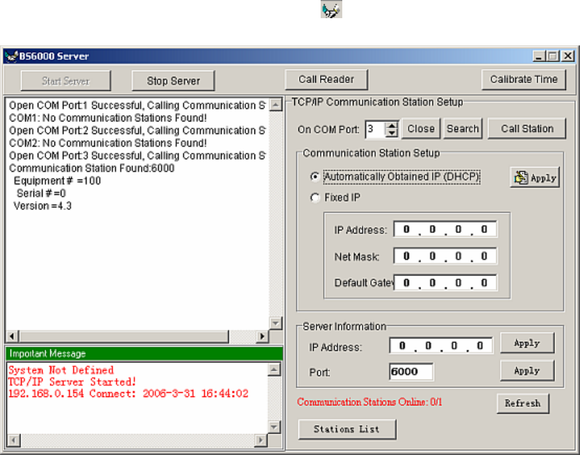
II. Setting Up the BS-6000 Communication Station
a) Start the BS-6000 software, double-click on its icon at the lower-right corner of your
screen to open the software’s main interface.
b) Click on “Search” to allow the software to find the connected BS-6000 Communication
Station.
c) After the BS-6000 is found, click on “Call Station” ensure that it is in proper working order.
If the BS-6000 does not respond on the first try (reports “busy”), please try again. The
BS-6000 hardware may have been going through a stage of its initialization and
communication processes which temporarily blocked the inquiry signal from the program.
d) Select the method of IP address assignment for the BS-6000 (DHCP or Fixed IP), press
“Apply” to send the setting to the station.
e) Enter the IP address and port used for the server PC, press “Apply” each time to send the
setting to the station.
f) Press “Close” to disconnect the BS-6000 from the software, and disconnect the BS-6000
hardware from the PC.
III. Using the BS-6000 Communication Station
a) The BS-6000 can be installed remotely by connecting to an Ethernet cable which provides a
access to a TCP/IP based network (LAN or Internet). If connecting via a router, be sure that
the port being used by the server is open in the router.
b) Power to the BS-6000 can be provided by a 4.2V battery when installed remotely, or by the
USB cable while performing setup function on the PC.
c) Uploading data from a guard tour reader to the BS-6000:
Place the reader on the BS-6000. If there is data present, after a few seconds, once the
communication link is established between the station and the reader, the blue LED light on
the BS-6000 will flash quickly, indicating that data is being uploaded. The BS-6000 will
make one long beep when data uploading from the reader is complete. The red LED next to
the green LED on the BS-6000 will turn on, indicating that it has data stored that needs to be
uploaded to the server.
d) Uploading data from the BS-6000 to the server:
Once it has data that needs to be uploaded, the BS-6000 will automatically attempt to
connect and upload to the server. This will occur after communication with a reader is
complete, and also when the BS-6000 is first powered up. If it does not succeed on the first
attempt, it will try again once every 30 seconds for the next 90 seconds. Afterwards, it will
wait for 3 minutes, and start trying again every 30 seconds for another 90 seconds. The cycle
continues until all unuploaded data has been uploaded. The red LED next to the green LED
will then turn off.
IV. Other Notes
a) The BS-6000 software can be used at the remote sites to diagnose and calibrate time on the
readers. After connecting the BS-6000 to the PC via the USB cable, the “Call Reader”
button will return the serial number and reseller ID number of the reader placed on the
station, and the “Calibrate Time” button will change the time setting on the reader to match
that of the PC’s clock.
b) The BS-6000 is able to upload its data directly to stand-alone patrol software programs by
connecting with the USB cable. (Just select “BS-6000, 3000, 4000 Communication Station”
during data upload). It is also able to act as a signal card reader.
c) The “Stations List” table, accessible from the main interface screen of the software, lists the
BS-6000 units that are currently connected, and also those that have successfully uploaded
data to the server in the past. (This does not include those that have only established
communication with the server software without uploading data.)
d) The software’s Server process must be stopped first before it can be shut down.
e) This device complies with Part 15 of the FCC Rules. Operation is subject to the following
two conditions: (1) this device may not cause harmful interference, and (2) this device must
accept any interference received, including interference that may cause undesired operation.
f) Changes or modifications not expressly approved by the party responsible for compliance
could void the user's authority to operate the equipment.
Appendix I: BS-6000 TCP/IP Remote Communication Station
Hardware Specifications
I. Specifications
a) Power supply: 4.2V direct current, or via USB connection cable.
b) Data storage type: FLASH memory, preserves data with or without electricity.
c) Data storage capacity: 49713 records.
d) Card reading format: EMID RFID.
e) Operating temperature: -20 C° to 70 C°
f) Operating humidity: 0% to 95%
II. LED Status Lights
(in the descriptions below, “up” indicates the direction on the BS-6000 where the status LED
lights are located):
a) Red LED – Upper-Left
i. Flashing: receiving data from a guard tour reader.
ii. Constant on: there is data that needs to be uploaded.
iii. Constant off: there is no data that needs to be uploaded.
b) Green LED – Lower-Left
i. Flashing once per second: the BS-6000 is operating normally.
c) Red LED – Upper-Right
i. Constant on: the Ethernet cable has been properly connected.
ii. Constant off: the ether net cable has not been properly connected.
d) Blue LED – Lower-Right
i. Flashing once per second: the BS-6000 is operating normally.
ii. Flashing quickly: the BS-6000 is communicating with the server via the TCP/IP
network.
III. Audio Signals
There are two types of audio signals: long beep and short beep.
Some of the audio signals below have multiple meanings depending on the situation.
a) Short Beep (once)
i. After powering up: the TCP/IP chipset is operating properly.
ii. After receiving TCP/IP related setup command from the PC: setup successful.
iii. After placing a guard tour reader on the unit: reader found, but the it does not contain
data that needs to be uploaded.
b) Short Beep (twice consecutively)
i. When attempting to communicate with the server: Ethernet cable not plugged in
properly.
ii. During communication with the server: error in data returned from server.
iii. After placing a guard tour reader on the unit: reader found, and it contains data that
needs to be uploaded.
c) Short Beep (three times consecutively)
i. While obtaining data from the reader: the BS-6000’s memory is full, please upload to
the server.
ii. When attempting to communicate with the server: failed to find the server.
d) Long Beep (once)
i. Data transfer is complete.
e) Long Beep (three times consecutively)
i. Data has been completely transferred from the BS-6000 to the server.
f) Long Beep (once) + Short Beep (three times)
i. The BS-6000 is not operable and needs to be initialized by the manufacturer.
Appendix II: BS-6000 TCP/IP Remote Communication Station
Troubleshooting Guide
I. After turning on the unit, its green and blue LED status lights do not flash.
a) This means that the unit was not properly reset. Please disconnect its power, and reconnect
after at least 3 seconds.
II. Nothing happens after placing a guard tour reader upon the unit.
a) Make sure that the BS-6000 is operating properly, and that its LED status lights are flashing
correctly.
b) Check to see if the reader is placed properly on the unit. The reading head of the reader
should be between the status lights of the unit, and its top should be flush against the inside
edge of the unit.
c) Please note that the BS-6000 unit is not able to upload data from guard tour readers when it
is communicating with the PC, or 10 seconds following its most recent communication with
the PC.
III. During setup (when the PC is connected to the BS-6000 via the USB cable), the BS-6000
does not respond to Call requests from the software.
a) Make sure that the BS-6000 is operating properly, and that its LED status lights are flashing
correctly.
b) Check in Windows Device Manager and make sure that the proper USB driver has been
installed for the BS-6000.
IV. The BS-6000 is not able to upload data to the server.
a) Make sure that the BS-6000 program has been started on the server, and its server function
has been started.
b) If the BS-6000 emits two consecutive short beeps while attempting to communicate with the
server, it means that the Ethernet cable is not properly connected.
c) Make sure that the TCP/IP and server settings on the BS-6000 unit is correct.