Bluetree Wireless Data BTX600 CDMA Wireless Radio Modem User Manual BT4600 5600 User Guide Draft1
Bluetree Wireless Data Inc. CDMA Wireless Radio Modem BT4600 5600 User Guide Draft1
User guide

BT4600 (IP Series)
BT5600 (GPS Series)
CDMA 1xEvDO Modems
Product Manual

BlueTree Wireless
BT4600 and BT5600 CDMA 1xEvDO Modems
Product Manual
November 2005
UG-BT4600 & BT5600 CDMA

BlueTree Wireless Data, Inc.
2425 46th Avenue
Lachine, QC, Canada H8T 3C9
Tel: +1 (514) 422-9110
Toll Free: 1-877-422-9110
www.bluetreewireless.com
Copyright © 2004/2005 by BlueTree Wireless Data, Inc.
All Rights Reserved
Printed in Canada
BlueTree™, the BlueTree logo, and BlueVue™ are trademarks of
BlueTree Wireless Data, Inc.
All other trademarks are the property of their respective owners.

Draft 1 BlueTree Wireless BT-4600/BT-5600 Product Manual 4
Patents
Portions of this product are covered by some or all of the following
patents:
Declaration of Conformity
FCC Compliance and Industry Canada Statement
FCC ID: (TBD)
Industry Canada: (TBD)
The device complies with Part 15 of FCC rules and with ICES-003 of
Industry Canada Rules. Operation is subject to the following two
conditions:
1. This device may not cause harmful interference.
2. This device must accept any interference received, including
interference that may cause undesired operation.
Caution: Unauthorized modifications or changes not expressly approved by
BlueTree Wireless Data, Inc. could void compliance with regulatory rules,
and thereby your authority to use this equipment.
This equipment generates uses and can radiate radio frequency energy
and, if not installed and used in accordance with the manufacturer's
instructions, may cause interference harmful to radio communications.
However, there is no guarantee that interference will not occur in a
particular installation. If this equipment does cause harmful
interference to radio or television reception, which can be determined
by turning the equipment off and on, the user is encouraged to try to
correct the interference by one or more of the following measures:
• Reorient or relocate the receiving antenna.
• Increase the separation between the equipment and receiver.
• Connect the equipment into an outlet on a circuit different from
that to which the receiver is connected.
• Consult the dealer or an experienced radio/TV technician for help.

Draft 1 BlueTree Wireless BT-4600/BT-5600 Product Manual 5
Warning: “Antenna must not exceed 3 dBi for Cellular band
and 4 dBi for PCS band. This device must be used in mobile
configurations. The antenna(s) used for this transmitter must
be installed to provide a separation distance of at least 30 cm
or 12 inches from all persons and must not be co-located or
operating in conjunction with any other antenna or transmitter.
Users and Installers must be provided with antenna installation
instruction and transmitter operating conditions for satisfying
RF exposure compliance”
Liability Notice
While every effort has been made to achieve technical accuracy,
information in this document is subject to change without notice and
does not represent a commitment on the part of BlueTree Wireless
Data, Inc., or any of its subsidies, affiliates, agents, licensors, or
resellers. There are no warranties, express or implied, with respect to
the content of this document.
Safety
Do not operate the BlueTree Wireless Data BT4600 or BT5600 modem
in areas near medical equipment, where blasting is in progress, where
explosive atmospheres may be present, or near any equipment that
may be susceptible to any form of radio interference.

Draft 1 BlueTree Wireless BT-4600/BT-5600 Product Manual 6
Contents
Chapter 1: Introduction .........................................................7
Welcome................................................................................... 7
Customer Support...................................................................... 7
Chapter 2: Product Description..............................................8
Overview .................................................................................. 8
Available Models ........................................................................ 8
Modem Features ........................................................................ 9
Operational Description..............................................................10
Physical Description...................................................................12
Technical Specifications..............................................................17
Chapter 3: Installation Requirements.................................. 18
Cellular antenna........................................................................18
GPS antenna ............................................................................18
Serial cable ..............................................................................19
Ethernet cable ..........................................................................19
USB cable ................................................................................19
Power source............................................................................19
Mounting Hardware ...................................................................19
Wireless network account...........................................................19
Chapter 4: Installing the Modem.......................................... 20
1) Unpacking the Modem............................................................20
2) Mounting the Modem .............................................................20
3) Installing the Cellular Antenna ................................................20
4) Installing the GPS Antenna .....................................................21
5) Installing the Power Cable ......................................................22
6) Connecting the Data Cables....................................................24
7) Configuring the modem..........................................................25
8) Connecting to a wireless network using the serial port (DB9).......25
9) Connecting to a wireless network using the Ethernet port (RJ45)..26
Appendix A: Warranty and Customer Support...................... 28
Warranty .................................................................................28

Draft 1 BlueTree Wireless BT-4600/BT-5600 Product Manual 7
Chapter 1: Introduction
Welcome
Thank you for choosing the BT4600/5600, BlueTree’s CDMA wireless
data modem.
Customer Support
Help desk Toll-free 1-877-422-9110
Phone (514) 422-9110
Hours 09:00 - 17:00 Eastern Time
Email support@bluetreewireless.com
Sales desk Phone (514) 422-9110
Hours 09:00 - 17:00 Eastern Time
Email info@bluetreewireless.com
Mail BlueTree Wireless Data, Inc.
2425 46th Avenue
Lachine, QC, Canada H8T 3C9
Fax (514) 422-3338
Web www.bluetreewireless.com

Draft 1 BlueTree Wireless BT-4600/BT-5600 Product Manual 8
Chapter 2: Product Description
Overview
The BT4600/5600 modem gives today's mobile organization the
reliable, instant access to information that is critical for its teams.
The unit is a fully integrated CDMA modem, which adds wireless
1xEvDO functionality to remote and mobile applications. These are
designed for harsh environment installations and are tested to meet
strict military and automotive standards.
These modems are intended for use with a host platform such as a
computer or remote data terminal unit. These modems also contain an
embedded processor and the intelligence to transfer data from one
source to another over the wireless network without the need for any
additional computing device.
BlueVue Device Manager software
The modem package also includes BlueVue Device Manager software.
The Device Manager application makes configuring and monitoring
your modem simple and quick. With this software modem
administrators can:
• Provision modem on wireless network (Activation)
• Configure operating parameters
• Monitor status information
Note: Refer to BlueVue Device Manager manual for more details.
Available Models
BlueTree offers two models of CDMA wireless rugged modem:
• BT4600 wireless modem - base model with TCP/IP capability.
• BT5600 wireless modem - GPS model with TCP/IP and positioning
capabilities.

Draft 1 BlueTree Wireless BT-4600/BT-5600 Product Manual 9
Modem Features
The BT4600/5600 modems offers the following features:
CDMA Dual-band Supports both North American frequency bands:
800 and 1900 MHz
CDMA 1xEvDO Compatible with CDMA IS-2000 (1xEvDO )
Wireless data services. Backward compatible with
IS95 protocols.
Short Message Services (SMS) Supports both mobile originate and mobile
terminate text messaging
3 different data connection
interfaces
Serial/RS-232, Ethernet, and USB.
Note: USB is not available on product release 1.0
TPC/IP Stack Fully integrated TCP/IP protocols allowing the
modem to connect autonomously to the packet
network (internet). This feature enables capabilities
such as: In-call diagnostic, Serial-IP, stand-alone
GPS, remote configuration, and remote firmware
upgrade.
In-call diagnostic Allows the user to get modem status information
while in a data call, without interrupting the data
session.
Serial-IP Encapsulates data coming from the serial port into
a TCP or UDP packet and sends it to a remote
server on the packet network. Decapsulates IP
packets coming from the network and sends raw
data to the serial port.
Remote configuration Using the BlueVue Device Manager, this feature
allows the administrator to remotely configure or
perform remote diagnostics on the modem.
Note: For more information, refer to the BlueVue
Device Manager manual.
Remote firmware upgrade Using the BlueVue Device Manager, this feature
allows the administrator to remotely upgrade the
modem’s firmware.
Note: For more information, refer to the BlueVue
Device Manager manual.
Remote access security For remote configuration, the modem offers access
protection through username and password
authentication.
Integrated GPS Receiver Available on the BT5600 only, a Trimble GPS
receiver is embedded into the modem for
Automatic Vehicle Location (AVL). The modem can
report this positioning data locally to any of the
data interfaces (serial, Ethernet, USB), or also
remotely to a predefined server (see stand-alone).
Draft 1 BlueTree Wireless BT-4600/BT-5600 Product Manual 10
Stand-alone GPS Available on the BT5600 only, this feature allows
remote asset tracking by sending GPS data to a
remote server without the need for a client
application on the data terminal.
Store and Forward Available on the BT5600 only, this feature allows
GPS data storage. If a unit loses communication,
the data being collected through GPS will be
stored in memory and forwarded when
communication is reestablished.
Inputs and Outputs Not available on the product release 1.0.
Operational Description
Wireless connection modes
The BT4600/5600 can connect to the wireless data network in three
different ways:
• Packet Data (1xEvDO/1xRTT): allows outgoing calls using
either IS-2000 1xEvDO or 1xRTT cellular protocols, in the same
order of priority. It is intended for TCP/IP connections to the
internet. 1xEvDO allows speed up to 2.4Mbps.
• Packet Data (1xRTT): allows outgoing calls only using either IS-
2000 1xEvDO cellular protocols. It is intended for TCP/IP
connections to the internet. 1xEvDO allows speed up to 2.4M.
• Packet Data (QNC): allows outgoing calls only using IS-95 QNC
cellular protocols. It is intended for TCP/IP connections to the
internet. QNC allows speeds of up to 14.4Kbps.
• Circuit Switched Data: allows for both outgoing and incoming
calls using the circuit-switched IS-95 cellular protocol. It is
intended for direct connections with a landline analog modem.
Allows speeds of up to 14.4Kbps.
Modem operating modes
The BT-5000/4000 series modems are capable of operating in two
different networking modes, Router and Simple Modem modes.
The mode that is in effect when a connection is established depends on
the modem startup configuration and/or on the dialing strings used
when a host or a terminal attached to the modem’s serial port initiates
a connection.

Draft 1 BlueTree Wireless BT-4600/BT-5600 Product Manual 11
Router mode: In router mode, the modem establishes a PPP Client
connection with the network on the WAN side while a PPP Server
accepts connections on the LAN side over the serial port. Packets are
routed between the two connections for proper forwarding.
Note: Ethernet and future USB LAN-side connections automatically
assume a router mode.
Simple Modem mode: In Simple Modem mode, there are no PPP
negotiations established by the modem. The modem simply operates
at the physical layer and the PPP negotiations are passed-through
between the LAN and WAN sides.
The next sections assume host connections over the serial port.
Modem configured to start in Always-On mode
The modem can be configured to start in Always On mode. The
modem configuration is accomplished using AT commands from a
connection terminal like Microsoft® HyperTerminal, or using BlueTree
Device Manager. Upon modem startup, this mode causes the modem
to automatically establish and maintain a PPP connection with the
network on the WAN side.
This connection requires a connection profile to be configured in the
modem prior to connecting.
Note: In this mode, the modem can achieve autonomous
communication, like reporting GPS data to preconfigured IP
destinations, without the need for a host.
When a host, attached to the serial port of a modem in the Always-On
mode, sends a dial command to the modem, the following connection
behavior applies:
• If the dial string is the special string “#BTPPPS” or is the same dial
string used in the modem connection profile of the modem, router
mode comes in effect, PPP server is started and accepts the
connection.
• If the dial string is not “#BTPPPS” and is different from the one
used in the configured connection profile, then the WAN-side
connection is terminated and the modem reverts to the Simple
Modem mode as described above.
Modem configured to start in On-Demand mode
In this mode, the same logic applies as in the Always-On mode with
the exception that the WAN connection is established only when a dial
command is received from the LAN-side.
If no connection profile is configured in the modem, the On-Demand
connection always puts the modem in Simple Modem mode except
when the “#BTPPPS” dial string is used. In this case, PPP server starts
on the LAN side and a PPP connection is established with the modem
only.
Draft 1 BlueTree Wireless BT-4600/BT-5600 Product Manual 12
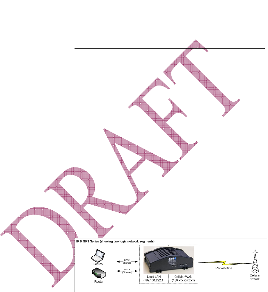
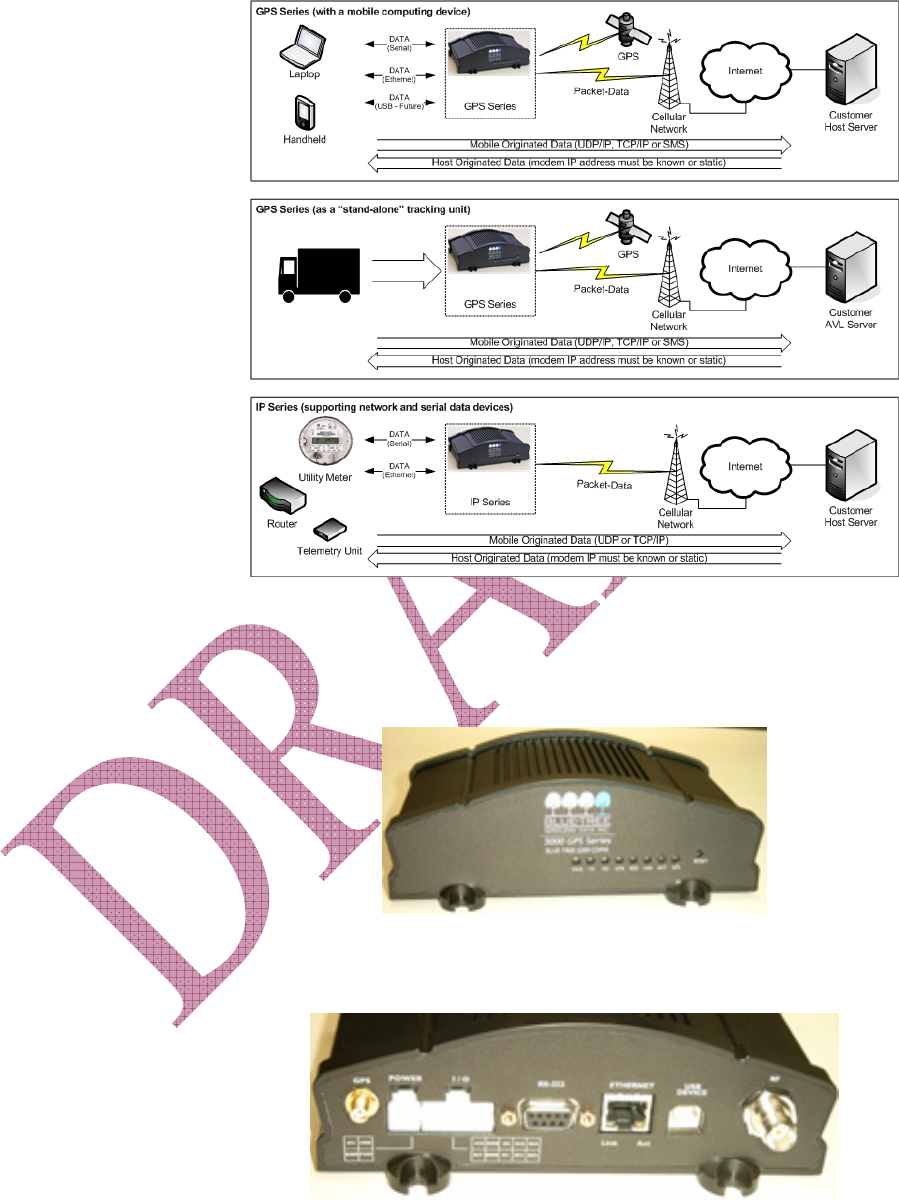
Diagrams of typical applications
Physical Description
Front View
Rear View
Draft 1 BlueTree Wireless BT-4600/BT-5600 Product Manual 13
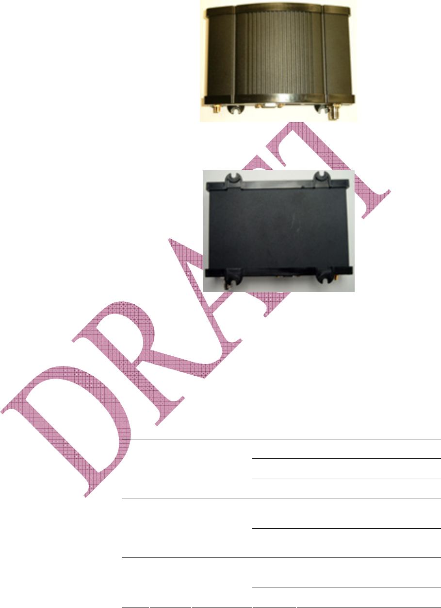
Top View
Bottom View
LED indicators
On the front plate of the modem, eight green LEDs are displayed:
PWR, TX, RX, DTR, REG, ACT, LNK, and SER or GPS.
Those eight indicators offer a user-friendly means of inquiring the
modem’s operating status. They are described in the table below.
Table: 1: LED description
LED Label Full Name Color Corresponding State
OFF Modem is turned OFF.
Flashing Modem failure.
1 PWR Power
ON Modem is ON.
OFF Terminal is not transmitting data to
modem.
2 TX Transmit
Flashing Terminal is transmitting data to
modem.
OFF Terminal is not receiving data from
modem.
3 RX Receive
Flashing Terminal is receiving from modem.
Draft 1 BlueTree Wireless BT-4600/BT-5600 Product Manual 14
OFF No terminal is detected.
Flashing Problem.
4 DTR Date Terminal
Ready
ON Terminal host is detected.
OFF Network not found.
Flashing Registered on network.
5 REG Registration
ON Searching for network.
OFF Not in a call.
Flashing In a circuit-switched call.
6 LNK RF link
ON In a packet-switched call.
OFF No transmit/receive from network. 7 ACT RF activity
Flashing Transmitting/receiving data from
network.
OFF AT command mode.
Flashing On-demand serial IP mode.
8 SER Serial mode
ON Always-on serial IP mode.
(Model BT4600 only)
OFF No position fix available.
Flashing 2D position fix is available.
9 GPS GPS
ON 3D position fix is available.
(Model BT5600 only)
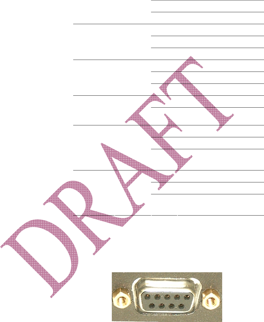
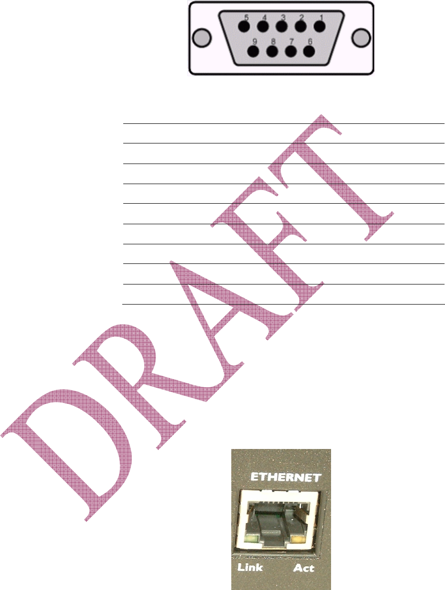
Serial Port (DB9)
The modem’s serial port is an RS232 DCE, compliant with EIA-232
standard. The connector used is DB9 female and is shown in the
illustration below.
Draft 1 BlueTree Wireless BT-4600/BT-5600 Product Manual 15
Table: 2: RS-232 connector pinout
Pin number Name Description Direction
1 DCD Data Carrier Detect Modem to PC
2 RXD Receive Data Modem to PC
3 TXD Transmit Data PC to Modem
4 DTR Data Terminal Ready PC to Modem
5 GND Ground Common
6 DSR Data Set Ready Modem to PC
7 RTS Request To Send PC to Modem
8 CTS Clear To Send Modem to PC
9 RI Ring Indicator Modem to PC
USB Port (Type B)
This feature is not supported on product version 1.0.
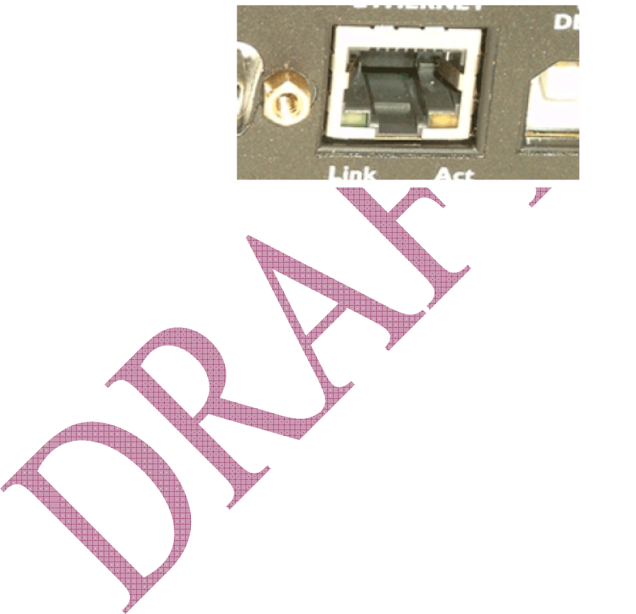
Ethernet Port (RJ-45)
The Ethernet port of the modem is configured as shown in the
illustration below. The Ethernet port is compliant to EIA-568 standard,
and requires a crossover cable to connect to host terminals.
Draft 1 BlueTree Wireless BT-4600/BT-5600 Product Manual 16
Table: 3: Ethernet connector pinout
Pin number Name Description Direction
1 TX+ Transmit + Modem to PC
2 TX- Transmit Modem to PC
3 RX+ Receive + PC to Modem
4 N.C. None None
5 N.C. None None
6 RX- Receive - PC to Modem
7 N.C. None None
8 N.C. None None
Input and Output Ports (Digital & Analog I/O)
This feature is not supported on product version 1.0
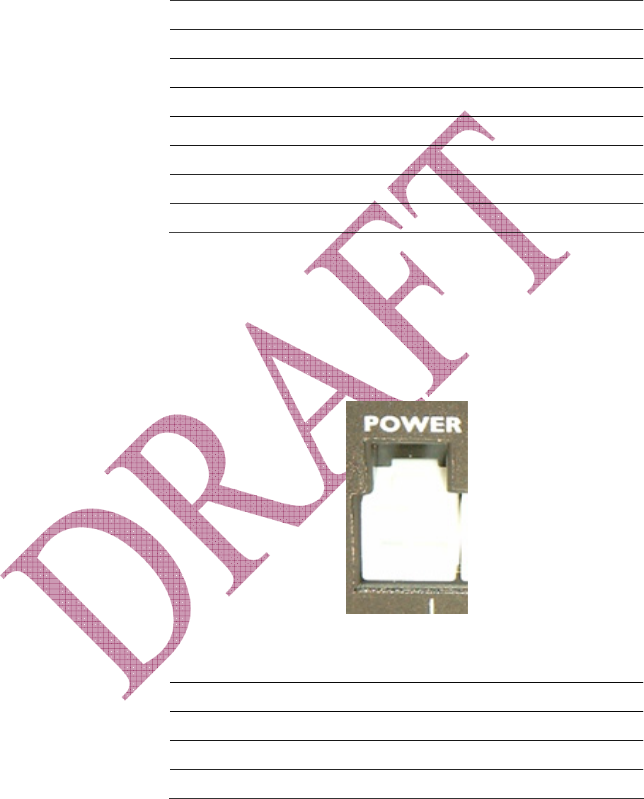
Power Connector
The power interface (or power supply) connector is configured as
described in the table below. The connector used for this application is
a MiniFit 4-pin Molex connector.
Table: 4: Power connector pinout
Pin number Name Description
1 GND Ground
2 POS Power supply input 8 to 30 Vdc
3 IGN Ignition sense
4 OUT Not connected

Draft 1 BlueTree Wireless BT-4600/BT-5600 Product Manual 17
Technical Specifications
Category Specification
Data Interface Connectors DB-9 female for serial RS232 (1200 to 115600 bps)
USB Type B receptacle
RJ-45 host female for Ethernet
Cellular Antenna Connector 2x SMA 50 ohm female
GPS Antenna Connector SMA 50 ohm female
Power Input 8.0 - 30VDC (nominal 12 VDC)
Current Consumption @ 12
VDC
Online: 150 mA (average), 300 mA (peak)
Standby: 40 mA
Ignition off: 1 mA
Cellular RF specifications Effective Radiated Power
0.327 W / 23 dBm at 1900 MHz
0.247 W / 23 dBm at 800 MHz
Receiver Sensitivity: -104 dBm
GPS specifications 8 channels, 32 corrolators
Protocols: NMEA 0183 v3.0, TSIP, TAIP
Accuracy:
Horizontal: <6 meters (50%), <9 meters (90%)
Altitude: <11 meters (50%), <18 meters (90%)
Velocity: 0.06 m/sec.
Frequency: 1575.42 MHz
Receiver Sensitivity: -118 dBm
Mechanical Dimensions: 6.5” x 4.0” x 1.6”
Weight: 400g (pounds)
Body Material: aluminum extrusion
Environmental Operating Temperature: -30 to +60 C
Storing Temperature: -30 to +85 C
Humidity: 95% non-condensing
Shock: MIL 810F/202G
Vibration: MIL 810F/202G
Class I Division 2: Not Applicable
Regulatory FCC Part 15 Class B
Industry Canada ICES-003
Draft 1 BlueTree Wireless BT-4600/BT-5600 Product Manual 18
Chapter 3: Installation Requirements
Cellular antenna
Before you install the modem you will need the following:
To comply with FCC and Industry Canada regulations, cellular
antennas must meet the following specifications:
• Maximum rated gain of 3dBi for Cellular band and 4dBi for PCS
band
• Dual-band 800 & 1900 MHz
• Nominal 50 ohm impedance
• VSWR less then 2.5:1
• Male SMA connector
It is recommended to use 2 cellular antennas (RF1 and RF2) for
diversity and improved signal quality.
Warning: Antenna must not exceed 3dBi for Cellular band
and 4dBi for PCS band. This device must be used in mobile
configurations. The antenna(s) used for this transmitter must
be installed to provide a separation distance of at least 30cm
or 12 inches from all persons and must not be co-located or
operated in conjunction with any other antenna or transmitter.
Users and installers must be provided with antenna installation
instruction and transmitter operating conditions for satisfying
RF exposure compliance.
Warning: Only approved antennas may be connected to the
modem. Unauthorized antennas, modifications, or
attachments could impair data quality, damage the modem, or
result in the violation of FCC regulations.
GPS antenna
The selected GPS antenna must meet the following specifications:
• Active antenna with 3.3 volts preamplifier
• Nominal 50 Ohms impedance
• Male SMA connector
• Frequency band: 1575 MHz
Note: The GPS feature is only available on the BT5600 model only.
Combined GPS and Cellular antennas are available. Contact your local
representative for more details.

Draft 1 BlueTree Wireless BT-4600/BT-5600 Product Manual 19
Serial cable
If you are connecting to the modem via serial port, you will need a
standards straight through RS-232 cable with DB9 male to DB9 female
connectors.
Ethernet cable
If you are connecting to the modem via the Ethernet port, you will
need a cross over Category 5, RJ-45 cable, compliant with EIA-568
standard.
USB cable
This feature is not supported on product version 1.0.
Power source
You will need to provide a 12 Vdc nominal power source to the modem
(8Vdc to 30Vdc). Please see electrical specifications for more details.
Mounting Hardware
For mounting, the modem requires four #4 screws (3/16”) pan or
fillister head, as well as corresponding lock washers.
Wireless network account
Contact your wireless service provider and request a CDMA account
activation with the “packet data” (1xEvDO) service option.
You will need to provide the service provider the Electronic Serial
Number (ESN) of the modem you wish to activate. The ESN is located
on a label under the modem.
The wireless service provider should give you the following parameters
for you to complete the activation:
• Mobile Directory Number (MDN). This is the10-digit telephone
number assigned to your unit, including the area code.
• Service Provisioning Lock Code which is a 6-digit number
representing the Master Lock Code (MSL).
• Mobile Station ID (MSID or IMSI or MIN). This is a 10-digit or 15-
digit number required for Local Number Portability, and is optional.
• Username/Password for packet network access.
Note: Keep a written record of the account information that your
wireless service provider gives you. Store it in a secure
location. You will need this information if required to re-enter
the account information.

Draft 1 BlueTree Wireless BT-4600/BT-5600 Product Manual 20
Chapter 4: Installing the Modem
Installing the modem is a nine-step process:
1. Unpacking the modem
2. Mounting the modem
3. Installing the cellular antenna
4. Installing the GPS antenna (BT5600 model only)
5. Installing the power cable
6. Connecting the data cables
7. Configuring the modem
8. Connecting to a wireless network using the serial port (DB9)
9. Connecting to a wireless network using the Ethernet port (RJ45)
1) Unpacking the Modem
When the modem arrives, check that the package contains the
following items:
• BT4600 or BT5600BT-1000 1010 1100 1110 2000 2010 modem
• 15-foot power cable with 2A in-line fuse
• Extra serial number label
• Quick Start Guide
Any items missing from this list, please call your local representative.
2) Mounting the Modem
Place the modem in a location where you can connect the power,
antenna and data cables (refer to mechanical dimensions).
3) Installing the Cellular Antenna
• Cellular band antennas should be mounted more than 30 cm (12
inches) from other antennas.
• Do not install the antenna in a closed metallic enclosure (such as a
cabinet or the trunk of a car).
• For safety reasons, mount the antenna at least 30 cm (12 inches)
away from the body of a person.
• The length of the antenna cable may affect the signal strength.
Choose the appropriate cable type and length refer to table below.

Draft 1 BlueTree Wireless BT-4600/BT-5600 Product Manual 21
Warning: Antenna must not exceed 3 dBi for Cellular band
and 4 dBi for PCS band. This device must be used in mobile
configurations. The antenna(s) used for this transmitter must
be installed to provide a separation distance of at least 30 cm
or 12 inches from all persons and must not be co-located or
operated in conjunction with any other antenna or transmitter.
Users and installers must be provided with antenna installation
instruction and transmitter operating conditions for satisfying
RF exposure compliance.
Recommended Cable type and maximum length:
Cable type Loss per 100 feet Recommended max length
8216 (RG58) 31 dB 20 ft.
8267 (RG213) 7.6 dB 40 ft.
LMR-400 3.9 dB 60 ft.
LMR-500 3.15 dB 80 ft.
LMR-600 2.5 dB 100 ft.
LMR-1200 1.26 dB 140 ft.
Installation procedure
1. Thread the antenna cable through the vehicle so the cable can
reach the front plate of the modem.
2. Connect the cable to the SMA connector finger tight. Do not use
tools.
4) Installing the GPS Antenna
For BT5600 models only, follow these steps to install the GPS antenna:
1. Thread the antenna cable through the vehicle so the cable can
reach the front plate of the modem.
2. Connect the cable to the SMA connector finger tight. Do not use
tools.
Draft 1 BlueTree Wireless BT-4600/BT-5600 Product Manual 22
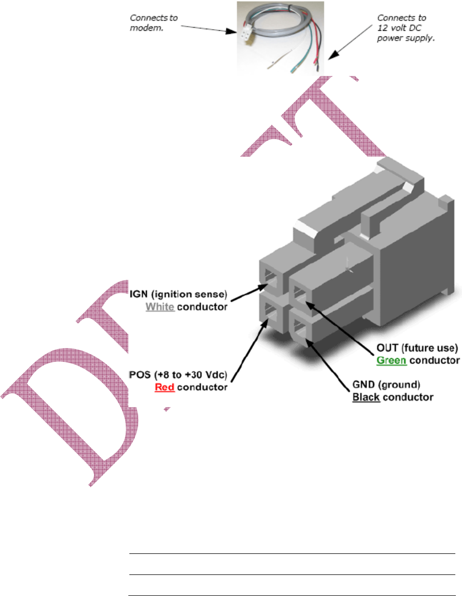
5) Installing the Power Cable
The modem includes a 15-foot power cable with 2A in-line fuse.
Power cable connector
As shown below, the power cable connects to the modem through a
Molex type connector (MiniFit 4-pin).
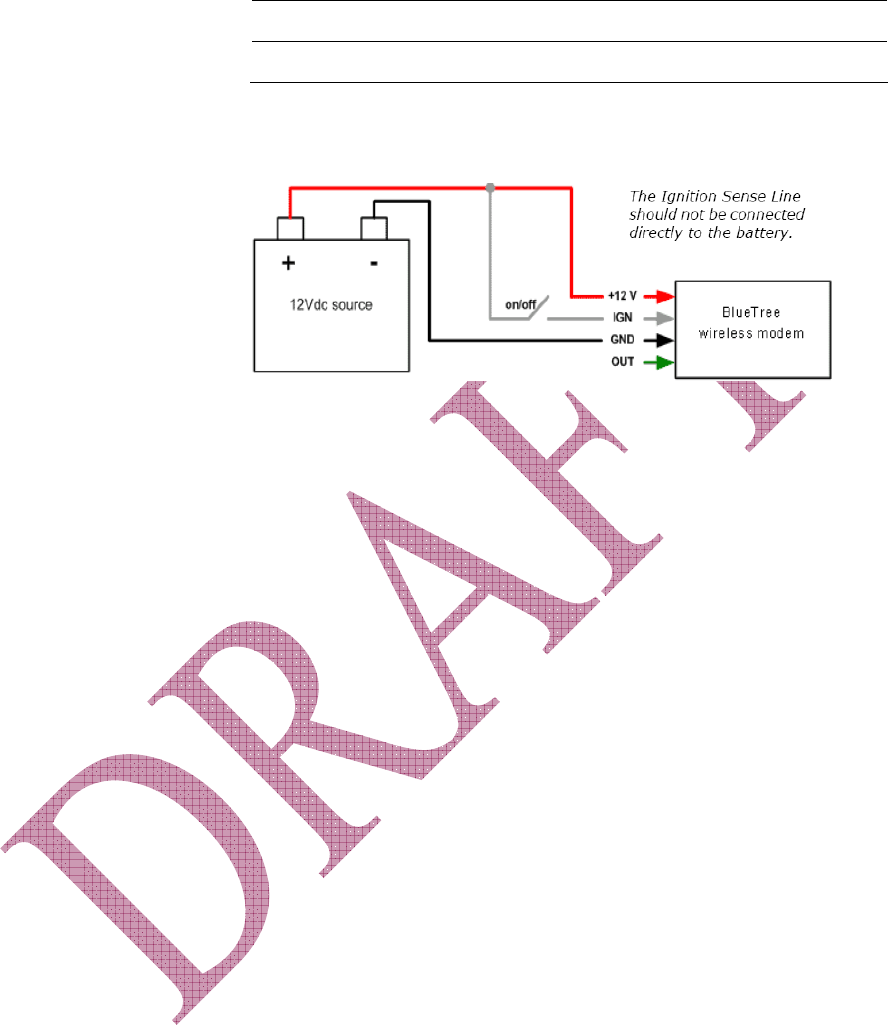
The ignition sense line (white wire) acts as an ON/OFF power switch.
The modem will turn on when the ignition sense line is set between 8
and 30 volts DC. The modem will turn off if the ignition sense line is
less than 5 volts DC.
Pin designations for the connector are shown below.
Pin Annotation Color Description
1 GND Black Ground
2 POS Red Power supply input 5 to 30 Vdc
Draft 1 BlueTree Wireless BT-4600/BT-5600 Product Manual 23
Pin Annotation Color Description
3 IGN White Ignition input
4 OUT Green Not used
Powering up the modem
Note: Make sure that the antenna is connected to the modem before
applying power.
The ignition Sense Line should not be connected directly to the
battery. Make sure that the antenna is connected to the modem before
applying power.
To connect the power cable:
• Connect the red wire directly to the battery’s positive (+) terminal
or to a source of 8-to-30Vdc.
• Connect the black wire directly to the battery’s negative (-)
terminal or to ground (GND).
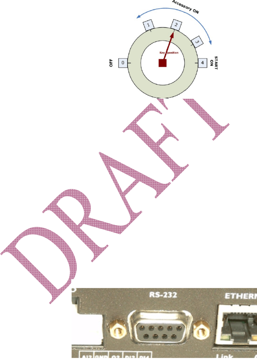
• The white wire must be connected to either:
a) a switch for manually turning on and off the modem,
b) the vehicle’s “Accessory for position 2”, for turning ON the
modem without turning on the engine,
c) the vehicle’s “Accessory for position 3”, for turning ON the
modem only when the engine is turned on.
Draft 1 BlueTree Wireless BT-4600/BT-5600 Product Manual 24
To test the power connection:
1. Check the modem’s LED indicators.
• If the PWR or Power indicator is turned on or if it flashes, the
modem is powered.
• If the PWR or Power indicator is not turned on, review the
installation procedures or see Troubleshooting section.
2. If LED indicators are not accessible to the installer a personal
computer can be used to verify it’s functionality.
• Start BlueVue Device Manager, it will automatically detect the
modem (refer to BlueVue Device Manager section).
• BlueVue Device Manager is not available initiate a Windows
HyperTerminal session and execute the AT commands shown
in Appendix C.
6) Connecting the Data Cables
Connecting the Serial data cable:
1. Connect one end of a serial cable to the modem at the connector
labeled RS-232.
Draft 1 BlueTree Wireless BT-4600/BT-5600 Product Manual 25
2. Connect the other end of the serial cable to an available
connection on your terminal.
Connecting the Ethernet data cable:
1. Connect one end the Ethernet cable to the modem at the
connector labelled ETHERNET.
2. Connect the other end of the Ethernet connection of your terminal.
Connecting the USB data cable:
This feature is not supported on product version 1.0
7) Configuring the modem
Once the physical installation is complete, the modem should be
configured for:
• Activation on the wireless network
• Operation mode and network connection setup
This configuration is performed using:
• BlueVue Device Manager companion software, or
• through standard AT commands (refer to AT Command manual).
8) Connecting to a wireless network using the serial
port (DB9)
Note: The following section is only required if you want to connect to
the network using a PC/laptop with Windows 2000/XP. It is
described here as an example of how a connection profile
should be configured to work with the BT4600/5600 modems.
Adding the modem
To add a modem in Windows 2000 or XP
1. Click Start > Settings > Control Panel > Phone and Modem
Options.

Draft 1 BlueTree Wireless BT-4600/BT-5600 Product Manual 26
2. On the Phone and Modem Options box, click the Modems tab and
then:
a) Click Add.
b) Check the box labelled “Don’t detect my modem;...” and then
click Next.
c) Select the Standard 33600 bps Modem and click Next.
d) Select the COM port that the modem is attached to then click
Next.
e) Click Finish to complete the addition of the modem in
Windows.
f) Click the Modem tab and confirm that the Maximum Port
Speed is set to 115,200.
g) Click OK.
The modem profile is now configured.
Creating the DUN profile
To create a Windows XP DUN connection:
1. Click Start > Settings > Control Panel > Network Connects > New
Connection Wizard.
2. On the New Connection Wizard welcome box click Next.
3. On the Network Connection Type box select Connect to the
Internet, and then click Next.
4. On the Getting Ready box select Set up my connection
manually, and then click Next.
5. On the Internet Connection box select Connect to a dialup
modem, and then click Next.
6. On the Select a Device box select the 33600bps modem and then
click Next.
7. On the Connection Name box, type in a name for the connection
(for example: CDMA) and then click Next.
8. On the Phone Number to Dial box type the phone number, as
supplied by your wireless service provider. For example, type
#777 for 1xEvDO packet data connections.
9. On the Internet Account Information box, type the username and
password in the corresponding fields and then click Next.
The DUN connection is now set up and ready to connect to the wireless
network.
9) Connecting to a wireless network using the
Ethernet port (RJ45)
Note: The following section is only required if you want to connect to
the network using a PC/laptop with Windows 2000/XP. It is

Draft 1 BlueTree Wireless BT-4600/BT-5600 Product Manual 27
described here as an example of how a LAN connection
between the PC and the BT4600/5600 modems is setup.
The BT4600/5600 modem has a DHCP server continuously running on
its RJ45 Ethernet interface. As soon as a PC is connected to it, the
modem will automatically assign and LAN IP address to the PC.
When this is done, the user will see the following message on its PC
monitor.

Draft 1 BlueTree Wireless BT-4600/BT-5600 Product Manual 28
Appendix A: Warranty and Customer Support
Warranty
The BT4600/5600 modem has a DHCP server continuously running on
its RJ45 Ethernet interface. As soon as a PC is connected to it, the
modem will automatically assign and LAN IP address to the PC.
When this is done, the user will see the following message on its PC
monitor.
Bluetree Wireless Data Inc. warrants the BT4600/5600 cellular modem
against all defects in materials and workmanship for a period of one
(1) year from the date of purchase. The sole responsibility of Bluetree
Wireless Data Inc. under this warranty is limited to either repair or, at
the option of Bluetree Wireless Data Inc., replacement of the cellular
modem. There are no expressed or implied warranties, including those
of fitness for a particular purpose or merchantability, which extend
beyond the face hereof. Bluetree Wireless Data Inc. is not liable for
any incidental or consequential damages arising from the use, misuse,
or installation of the BT4600/5600 cellular modem. This warranty does
not apply if the serial number label has been removed, or if the cellular
modem has been subjected to physical abuse, improper installation, or
modification. The unit is automatically registered for warranty at the
date it is purchased and/or shipped.