Bmc Heat Pump Gta3600Ud1Aa Users Manual 2100 537(I) (2012 10)
2015-02-02
: Bmc Bmc-Bmc-Heat-Pump-Gta3600Ud1Aa-Users-Manual-483736 bmc-bmc-heat-pump-gta3600ud1aa-users-manual-483736 bmc pdf
Open the PDF directly: View PDF ![]() .
.
Page Count: 54
Manual 2100-537
I
Page 1 of 54
Earth Loop Fluid
Temperatures 25° - 110°
Ground Water Temperatures 45° - 75°
BMC, Inc.
Bryan, Ohio 43506
Manual: 2100-537I
Supersedes: 2100-537H
File: Volume I, Tab 8
Date: 10-11-12
INSTALLATION
INSTRUCTIONS
MIS-2830
WATER SOURCE HEAT PUMP
MODELS:
GTB1-A Blower Section
GTA3600UD1AA Coil Section
GTA4860UD1AA Coil Section
GTADP-3642-B Coil Section
GTADP-3642-C Coil Section
GTADP-4860-C Coil Section
GTC36S2-ADCX Compressor Section
GTC48S2-ADCX Compressor Section
GTC60S2-ADCX Compressor Section
GTC36S2-ADNX Compressor Section
GTC48S2-ADNX Compressor Section
GTC60S2-ADNX Compressor Section
Manufactured under the following
U.S. patent number:
8,127,566

Manual 2100-537
I
Page 2 of 54
CONTENTS
Getting Other Informations and Publications ..............3
General Information Geo-Trio (GT Series)
Water Source Nomenclature .................................................... 4
Blower Conversion & Line Power Connect ............................ 15
Application and Location
General ............................................................................ 18
Shipping Damage ................................................................... 18
Application ............................................................................ 18
Dual Fuel Heating / Cooling ................................................... 18
Location ............................................................................ 18
Ductwork ............................................................................ 18
Filters ............................................................................ 19
Condensate Drain .................................................................. 19
Piping Access to Unit .............................................................. 19
Wiring Instructions
General ............................................................................ 22
Control Circuit Wiring.............................................................. 22
Wall Thermostats & Low Voltage Connections ....................... 22
Ground Loop (Earth Coupled Water Loop Applications)
Note ............................................................................ 24
Circulation System Design ..................................................... 24
Start Up Procedure for Ground Loop System ........................ 25
Ground Water (Well System Applications)
Note ............................................................................ 27
Water Connections ................................................................. 27
Well Pump Sizing ...........................................................27 & 28
Start Up Procedure for Ground Water System ....................... 29
Water Corrosion .............................................................29 & 30
Remedies of Water Problems ................................................. 30
Lake and/or Pond Installations ....................................... 30 & 31
Desuperheater
Description ............................................................................ 32
Location ............................................................................ 32
Electrical Connection .............................................................. 32
Installation Procedure - General ............................................. 32
Oper. of Heat Recovery Unit .................................................. 33
Start Up & Checkout ............................................................... 33
Maintenance & Control Board Seq. of Operation ........... 33 & 37
Sequence of Operation
Blower ............................................................................ 38
Part / Full Load Cooling .......................................................... 38
Part / Full Load Heating .......................................................... 38
Supplementary Electric Heat .................................................. 38
Geothermal Logic Controls ..................................................... 38
High / Low Pressure Switch ................................................... 39
Freeze Stat ............................................................................ 39
Condensate Overow ............................................................ 39
Under/Over Voltage Protection ............................................... 39
Intelligent Reset ...................................................................... 39
Alarm Output .......................................................................... 39
Pressure Service Ports ........................................................... 39
System Start Up ..................................................................... 39
Refrigerant Charge
Line Set Installation (GTA Coil Sections) ................................ 42
Charge Adjustment .............................................................. 42
Refrigerant Fitting Attachment ............................................ 42
Checking Charge Quantity ..................................................... 42
General / GTADP Coi Sections .............................................. 43
Line Set Installation (GTADP Coil Sections) ........................... 43
General / Topping Off System / Safety Practices ................... 44
Service
Service Hints .......................................................................... 47
Unbrazing System Components ............................................. 47
Compressor Solenoid ............................................................. 47
Troubleshooting GE ECM 2.3 Motors .............................48 & 49
Troubleshooting Table ............................................................ 50
Power Connector Table .......................................................... 50
Ground Source Heat Pump
Performance Report ................................................51-52
Wiring Diagrams ......................................................53-54
Figures
Figure 1A GTA****UD1AA Dimensions ................................. 7
Figure 1B GTADP Fossil Fuel ADP Coil Dimensions ............ 8
Figure 1C GTB1-A Dimensions ............................................. 9
Figure 1D GTC**S2-D Dimensions ..................................... 10
Figure 1E Assembled Upow/Counterow App. .................11
Figure 1F Horizontal App. Dimensions ............................... 12
Figure 2A Upow & Counterow Ducting Cong. ................. 13
Figure 2B Horiz. & Counterow Ducting Cong. .................. 14
Figure 3 Blower Conguration .......................................... 16
Figure 4 Blower Power Connections ................................ 17
Figure 5A Upow Air Filter Applications .............................. 21
Figure 5B Counterow Air Filter Applications ...................... 21
Figure 5C Horiz. Left Discharge Air Filter App. .................... 21
Figure 5D Horiz. Front Discharge App. ............................... 21
Figure 6 Thermostat Wiring .............................................. 23
Figure 7 Circulation System Design ................................. 24
Figure 8 Temperature & Pressure Measurement .............. 26
Figure 9 Perf. Model DORFC-1 Flow Ctr. ......................... 26
Figure 10 Perf. Model DORFC-2 Flow Ctr. ......................... 26
Figure 11 Water Connection Components.......................... 28
Figure 12 Cleaning Water Coil ............................................ 30
Figure 13 Lake or Pond Installation .................................... 31
Figure 14 Wiring Diagram ................................................... 34
Figure 15A Desuperheater Single Tank System ...................... 35
Figure 15B Desuperheater Dual Tank System ....................... 36
Figure 16 Thermistor .......................................................... 37
Figure 17 Component Location .......................................... 40
Figure 18 Control Panel ...................................................... 40
Figure 19 Refrigerant Flow Diagrams ................................. 41
Figure 20 Coil Spacer ......................................................... 43
Figure 21 Pressure Tables .................................................. 45
Figure 22 Control Disassembly ........................................... 49
Figure 23 Winding Test ....................................................... 49
Figure 24 Drip Loop ............................................................ 49
Figure 25 Control Connector Motor Half ............................. 50
Tables
Table 1 Indoor Blower Performance .................................. 5
Table 2 Flow Rates for Various Fluids ............................... 5
Table 3 Specications ....................................................... 5
Table 4 Water Coil Pressure Drop ..................................... 6
Table 5 Electrical Heat Specications ............................. 19
Table 6 Filter Sizing Chart ............................................... 20
Table 7 Control Circuit Wiring .......................................... 22
Table 8 Constant Flow Valves ......................................... 27
Table 9 Pre-Charged Line Set Qty .................................. 42
Quick Reference Troubleshooting Chart ................................ 46

Manual 2100-537
I
Page 3 of 54
GETTING OTHER INFORMATION AND PUBLICATIONS
These publications can help you install the air
conditioner or heat pump. You can usually nd these
at your local library or purchase them directly from the
publisher. Be sure to consult current edition of each
standard.
National Electrical Code .......................ANSI/NFPA 70
Standard for the Installation ...............ANSI/NFPA 90A
of Air Conditioning and Ventilating Systems
Standard for Warm Air ....................... ANSI/NFPA 90B
Heating and Air Conditioning Systems
Load Calculation for Residential ......ACCA Manual J
Winter and Summer Air Conditioning
Duct Design for Residential .............. ACCA Manual D
Winter and Summer Air Conditioning and Equipment
Selection
Closed-Loop/Ground Source Heat Pump ........IGSHPA
Systems Installation Guide
Grouting Procedures for Ground-Source .........IGSHPA
Heat Pump Systems
Soil and Rock Classication for ......................IGSHPA
the Design of Ground-Coupled Heat Pump Systems
Ground Source Installation Standards .............IGSHPA
Closed-Loop Geothermal Systems ..................IGSHPA
– Slinky Installation Guide
FOR MORE INFORMATION, CONTACT
THESE PUBLISHERS:
ACCA Air Conditioning Contractors of America
1712 New Hampshire Avenue
Washington, DC 20009
Telephone: (202) 483-9370
Fax: (202) 234-4721
ANSI American National Standards Institute
11 West Street, 13th Floor
New York, NY 10036
Telephone: (212) 642-4900
Fax: (212) 302-1286
ASHRAE American Society of Heating Refrigerating,
and Air Conditioning Engineers, Inc.
1791 Tullie Circle, N.E.
Atlanta, GA 30329-2305
Telephone: (404) 636-8400
Fax: (404) 321-5478
NFPA National Fire Protection Association
Batterymarch Park
P.O. Box 9101
Quincy, MA 02269-9901
Telephone: (800) 344-3555
Fax: (617) 984-7057
IGSHPA International Ground Source
Heat Pump Association
490 Cordell South
Stillwater, OK 74078-8018
Manual 2100-537
I
Page 4 of 54
Geo-Trio™ GT Series Geothermal / Water Source Heat Pump Nomenclature
GT B 1 – A
Option
A = 230 Volt 1-Phase
B = Blower
Section
Revision
Level
Geo-Trio
Blower Section
GT ADP – 3642 – B
B = 17.50" Wide Furnace
C = 21.00" Wide Furnace
ADP = Advanced
Distributor Products
3642 (3 Ton)
4860 (4 & 5 Ton)
Geo-Trio
Fossil Fuel “A” Coil Section
GT A 3600 UD 1 A A
Revision
Level
Series
“A” = Coil Section
Geo-Trio 3600 (3 Ton)
4860 (4 & 5 Ton) A = E Coated Coils
Option
“A” Coil Section
GT C 36 S 2 – A D C X
D = Desuperheater
S = Step Capacity
C = Compressor
Section
X = Future
Use
C = Copper Coil
N = Cupronickel Coil
A = 230 Volt 1-Phase
Nominal Capacity
36 = 36K
48 = 48K
60 = 60K
Revision
Level
Option
Geo-Trio
Compressor Section
Manual 2100-537
I
Page 5 of 54
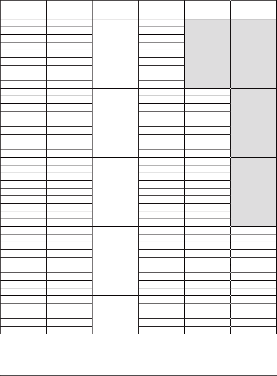
TABLE 1 — INDOOR BLOWER PERFORMANCE (RATED CFM)
Motorwillautomaticallystepthroughthevariousairowswiththermostaticcontrol
ESP = External Static Pressure (inches of water)
- Maximum allowable duct static
ContinuousairowistheCFMbeingcirculatedwithmanualfanoperationwithoutanyadditionalfunctionoccurring.
Willoccurautomaticallyforrst5minutesofPartLoadCoolingOperation.
WilloccurautomaticallyafterveminutesofPartLoadCoolingOperation.
Will occur automatically with control signal input.
As per ASHRAE Guidelines of 500 FPM Velocities.
MODEL
Rated
ESP
-
MAX
ESP
Continuous
Airow
Mild Climate
Operation
in Part Load
Cooling
Part Load
Airow
Full Load
Airow
Electric Heat
Airow
Minimum Air
Filter Face
Area Ft.2
GTC36S2 0.15 0.60 600 700 850 1200 1300 2.6
GTC48S2 0.20 0.60 750 875 1075 1500 1600 3.2
GTC60S2 0.20 0.60 900 1050 1300 1800 1800 3.6
APPLICATION MODELS
GTC36S2 GTC48S2 GTC60S2
Ground Loop (15% Methanol, Propylene Glycol, etc.) 8 12 15
Ground Water 6 7 9
Water Loop (Cooling Tower) 9.2 12.1 14.3
MODEL GTC36S2 GTC48S2 GTC60S2
Electrical Rating (60HZ/1PH) 230/208-60-1
Operating Voltage Range 253-197 VAC
Minimum Circuit Ampacity 24.5 33.1 39.7
+Field Wire Size #10 #6 #4
Ground Wire Size #10 #10 #10
++Delay Fuse or Circuit Breaker Max. 35 50 60
COMPRESSOR
Volts 230/208-60-1
Rated Load Amps (230/208) 10.6 / 11.9 15.3 / 17.0 20.2 / 22.7
Branch Circuit Selection Current 15.3 21.2 25.6
Locked Rotor Amps (230/208) 82 / 82 104 / 104 153 / 153
BLOWER MOTOR
Horsepower (ECM Motor) 3/4 Variable Speed
Volts 230/208-60-1
Motor Amps (Stage #2 @ Rated CFM) 3.4 4.3 4.4
FLOW CENTER (Based on DORFC-2)
Volts 230/208-60-1
Amps 2.14 2.14 2.14
DESUPERHEATER PUMP MOTOR
Volts 230/208-60-1
Amps 0.15 0.15 0.15
TABLE 2 — FLOW RATES FOR VARIOUS FLUIDS
TABLE 3 — SPECIFICATIONS
+75°C copper wire ++ HACR type circuit breaker
NOTE: All values can be changed + 10% via the + adjustment dip switches on the tap select control inclusive in the GTB1-A Blower Section
(see instructions later in this manual, or on wiring diagram in blower section).
Manual 2100-537
I
Page 6 of 54
TABLE 4
WATER COIL PRESSURE DROP
Model GTC36S2 GTC48S2 GTC60S2
GPM PSID Ft. Hd. PSID Ft. Hd. PSID Ft. Hd.
3 0.1 0.23
4 0.5 1.15 0.9 2.08
5 1.2 2.77 1.4 3.23
6 1.7 3.92 2.3 5.31
7 2.3 5.31 3.2 7.38 2 4.61
8 3.1 7.15 4.1 9.46 2.5 5.77
9 4.1 9.46 5.1 11.77 3.2 7.38
10 6.1 14.07 3.9 9.00
11 7.1 16.38 4.7 10.84
12 8.2 18.92 5.5 12.69
13 9.4 21.69 6.4 14.76
14 10.6 24.45 7.3 16.84
15 8.1 18.69
16 9 20.76
17 9.9 22.84
18
Manual 2100-537
I
Page 7 of 54
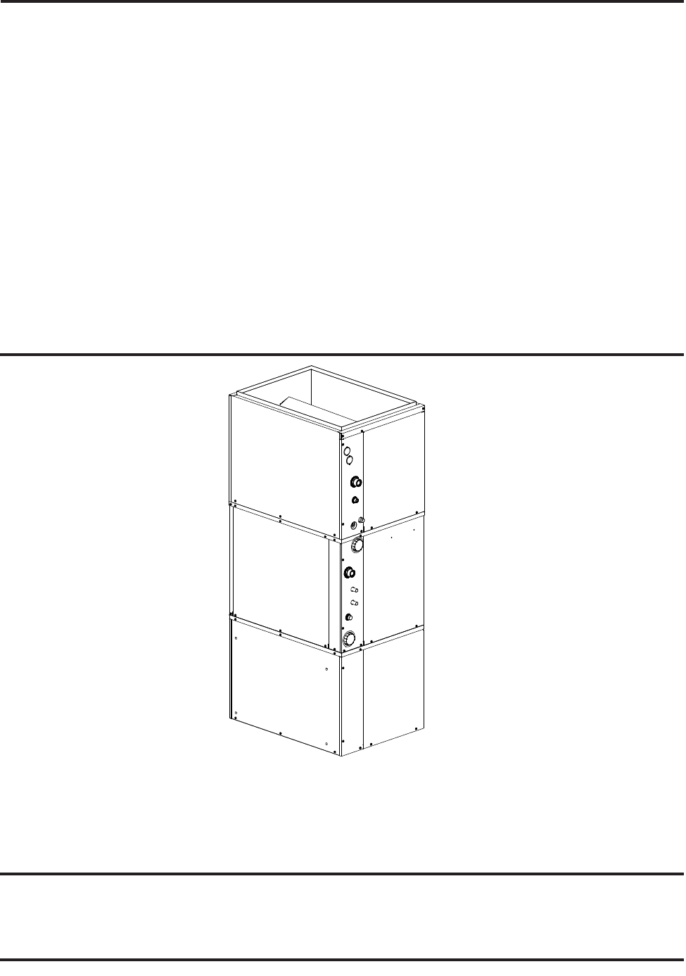
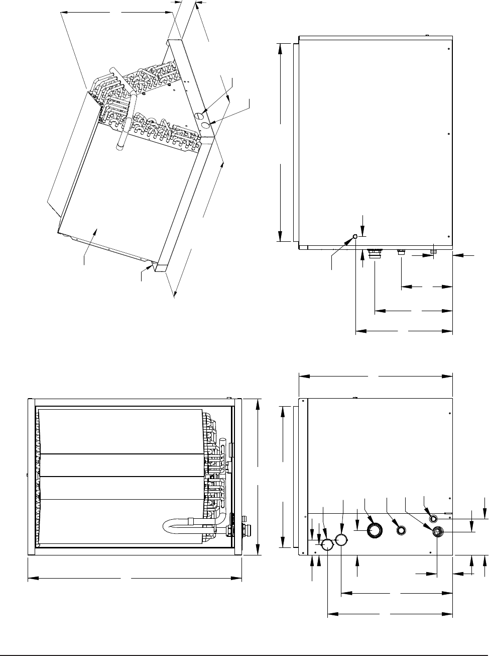
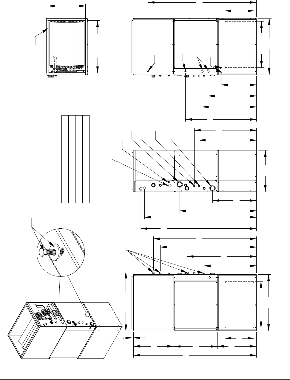
FIGURE 1A – GTA****UD1AA
A-COIL SECTION DIMENSIONS
2 3/16"
3 5/16" 5 1/8"
15 11/16"
17 5/8"
1 1/2"
10 15/16"7 1/4" 2 3/4"
MIS-2818
HORIZ. MAINDRAIN K.O.
HORIZ. OVERFLOW K.O.
SUCTION CONNECTION
LIQUID CONNECTION
OVERFLOW
MAINDRAIN
19 15/16"
3 1/2" 21 5/8"
2 3/16" CONDENSATE
OVERFLOW WIRES
27 15/16"
13 5/8"
113/16"
22"
30"
20.50-.000
+.125WIDTH
16.13-.000
+.125HEIGHT
DRAIN PAN
GTA Coil Dimensions If Used Without Cabinet
PRIMARY DRAIN HOLE
SECONDARY DRAIN HOLE
MIS-2876 A
COATED
COIL
.125
2.25-.000
+
28.25-.000
+.125 DEPTH
Manual 2100-537
I
Page 8 of 54
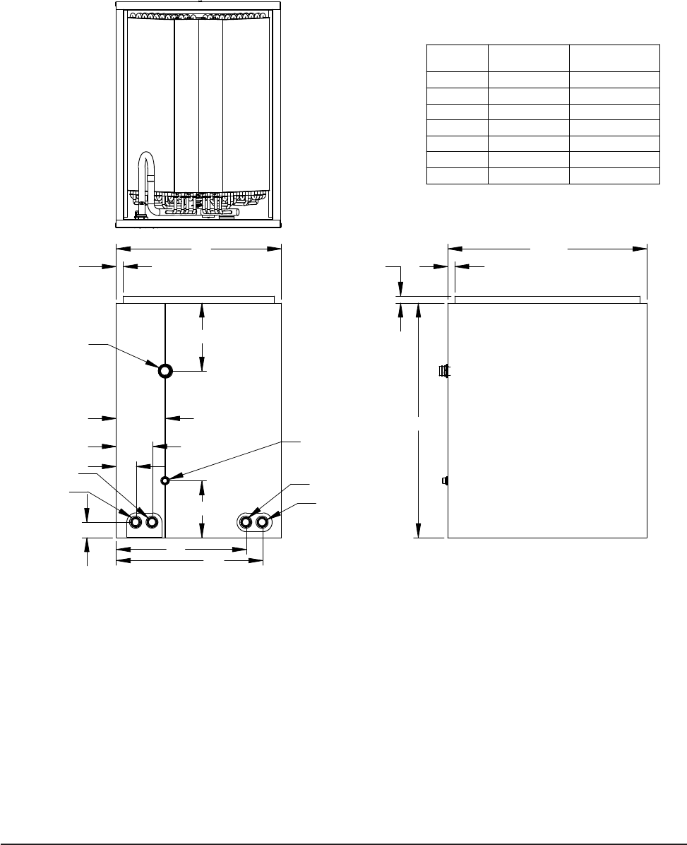
FIGURE 1B – GTADP****-*
FOSSIL FUEL ADP COIL SECTION DIMENSIONS
TYP
21 1/4"
"B"
3/4"
3/4"
TYP
MAIN DRAIN
CONNECTION
MAIN DRAIN
SUCTION
CONNECTION
OVERFLOW
LIQUID
OVERFLOW
"F"
"A"
"E"
"C"
6 1/16"
TYP
5 1/4"
"D"
1 5/8"
3/4"
"G"
FOSSIL FUEL ADP COIL SECTION DIMENSIONS
MIS-3119
FIGURE 1B - GTADP****-*
DIMENSION GTADP-3642-B GTADP-3642-C
GTADP-4860-C
"A" 17 5/8" 21 1/8"
"B" 25 1/2" 27 1/2"
"C" 7 1/4" 6 3/4"
"D" 2 1/8" 2 1/2"
"E" 3 7/8" 4 1/4"
"F" 13 7/8" 16 7/8"
"G" 15 5/8" 18 5/8"
Manual 2100-537
I
Page 9 of 54
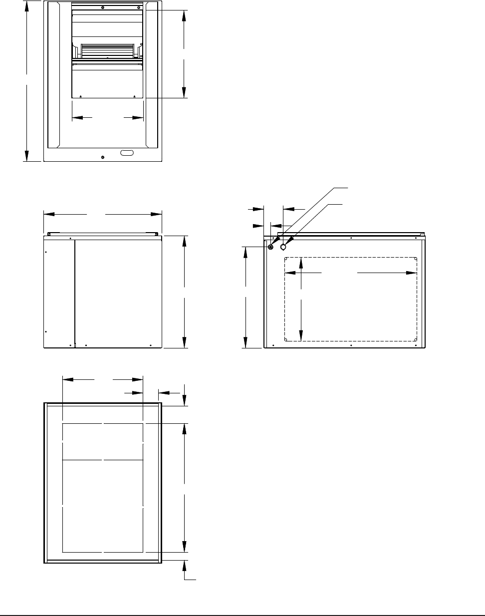
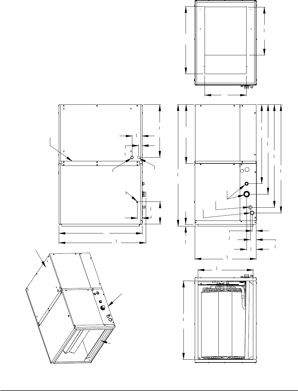
FIGURE 1C – GTB1-A
BLOWER SECTION DIMENSIONS
15 5/8"
24 9/16"
MIS-2819
30"
13 1/4"
16 3/8"
LOW VOLTAGE ENTRANCE
OPENING ON BOTH SIDES
OPTIONAL SIDE RETURN
HIGH VOLTAGE K.O. FOR
REMOTE APPLICATIONS ONLY
3 5/8"
18 13/16"
1 1/4"
24"
15"
3 5/16"
1 1/2"
2 7/8"
21"
22"
Manual 2100-537
I
Page 10 of 54
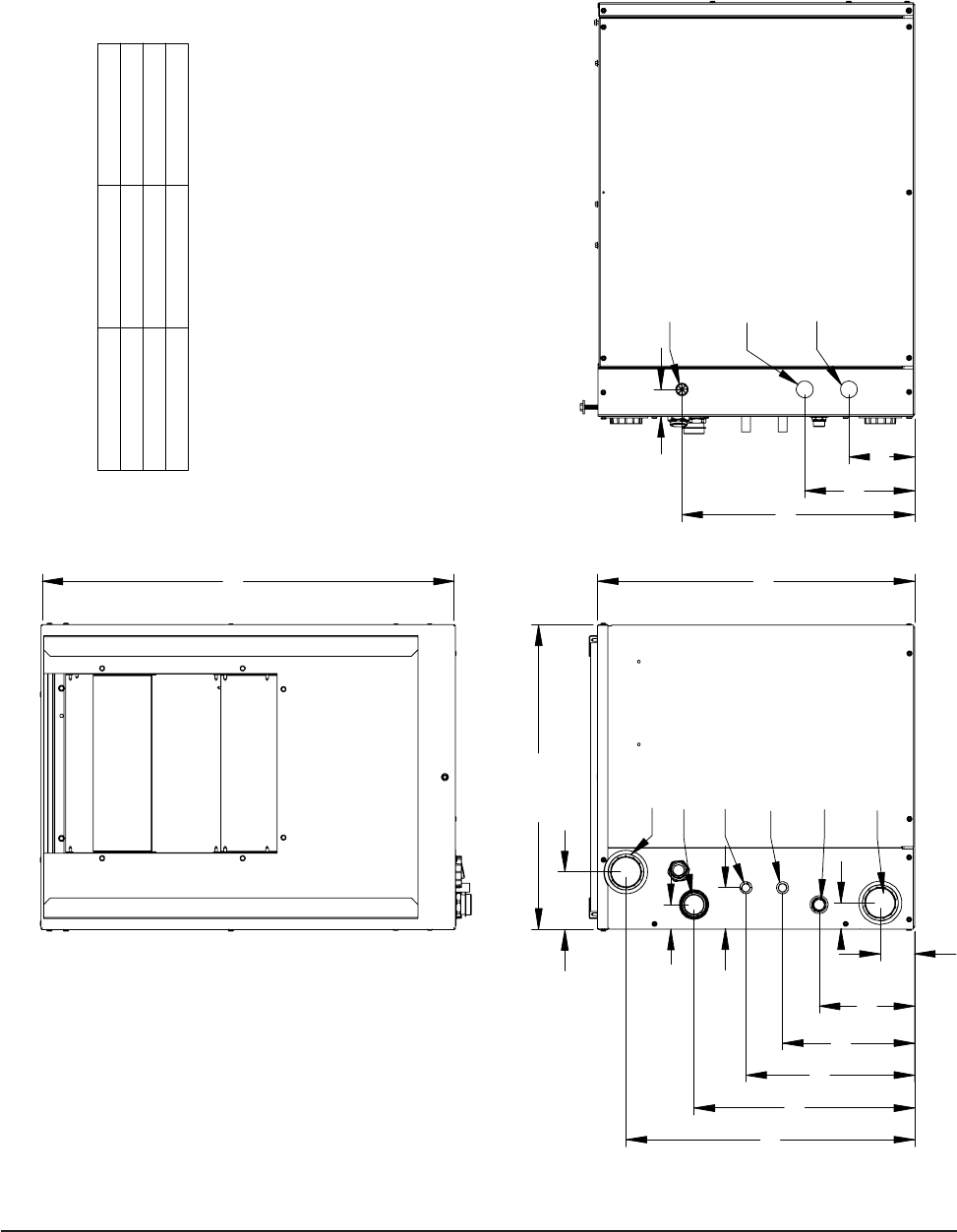
FIGURE 1D – GTC**S2-D
COMPRESSOR SECTION DIMENSIONS
MODEL DIM. A DIM. B
GTC36S2 21" 4 1/8"
GTC48S2 20" 3 7/8"
GTC60S2 18 1/2" 3 3/4"
DESUPERHEATER
WATER OUT
LIQUID LINE
SUCTION LINE
WATER IN
WATER OUT
DESUPERHEATER
WATER IN
12 1/4"
3"
9 5/8"
B
2 1/2"
23 1/16"
1 7/8"
16 1/16"
6 15/16"
A
1 3/4"
22 1/16"
30"
HIGH VOLTAGE UNIT
LOW VOLTAGE WIRE ENTRANCE
POWER ENTRANCE
HIGH VOLTAGE OPTIONAL
FLOW CENTER WIRE ENTRANCE
MIS-2820 A
8"4 13/16"
16 15/16"
1 15/16"
Manual 2100-537
I
Page 11 of 54
FIGURE 1E – ASSEMBLED UPFLOW / COUNTERFLOW APPLICATION DIMENSIONS
15 5/8"
24 9/16"
27 7/8"
37 1/16"
51 1/4"
55"
24 9/16"
15 5/8"
VOLTAGE
LOW
VOLTAGE
LOW VOLTAGE
HIGH
LOW VOLTAGE
18 13/16"
57 7/8"
25 3/4"
28 15/16"
37 7/8"
30"
REFRIGERANT
CONNECTIONS
65 5/8"
30"
21"
23"
21 5/8"
3/4" 31 1/4"
TOP DUCT OUTLET FLANGE
27 15/16"
19 13/16"
SECURE SECTIONS TOGETHER
USING BOLT PART #1012-015
AND WASHER PART #1012-109
MAIN DRAIN OUTLET
INLET
OVERFLOW DRAIN OUTLET
WATER OUT
OUTLET
DESUPERHEATER
DESUPERHEATER
WATER IN
61 5/8"
59 11/16"
33 1/4"
22"
23 7/16" 30 9/16"
"A"
MODEL DIM. A
GTC36S2 39 7/16"
GTC48S2 40 15/16"
GTC60S2 41 15/16"
RIGHT SIDEFRONT
LEFT SIDE
(UPFLOW ONLY)
ENTRANCE
TOP
AIR
(UPFLOW ONLY)
AIR
ENTRANCE
MIS-2821 B
Manual 2100-537
I
Page 12 of 54
FIGURE 1F – HORIZONTAL APPLICATION DIMENSIONS
36
5
8
"
38
1
2
"
1
1
2
"
2
1
8
"
Section
Blower
Section
Evaporator
GTHZ1
Horizontal
Drain Pan
(Req'd)
Horiz. Support Bracket
Low Voltage
Entrance
High Voltage
Entrance
Low Voltage
Entrance
Top View
30"
"
"
"
4
31
1
"
4
18
3
"
1
4
2
1
1
3
1
3
4
8"
Front View
7
"27
8
19
7
8
"
Opening
Evaporator Opening Blower
Right Side View
24"
15"
17
1
8
"
Overflow Drain
Outlet
Outlet
Main Drain
Refrigerant
Connections
7
"31
8
"
21"
8
22
1
"
3
8
"
4
43
3
"
8
28
1
3
1
2
"
MIS-2824
Left Side View
Evaporator and Blower in Horizontal Position
(Remote Compressor Section)
NOTE:
Requires
horizontal
drain pan kit
Model GTHZ-1
Manual 2100-537
I
Page 13 of 54
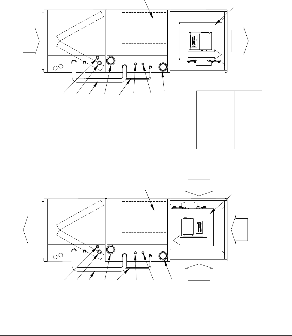
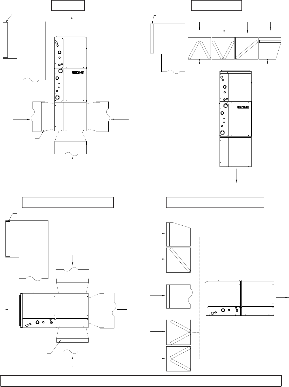
FIGURE 2A – UPFLOW & COUNTERFLOW DUCTING CONFIGURATIONS
Blower Air
Evap. Coil
Counterflow
Position
Cond. Coil
Water Out
Cond. Coil
Desuper.
Water In
Water In
Desuper.
Water Out
Supply
Return
Main Drain
Blower in
Alternate Position
7/8" Line Set
3/8" Line Set
Blower Air
Evap. Coil
Upflow
Cond. Coil
Position
Cond. Coil
Water Out
Desuper.
Water In
Desuper.
Water In
Water Out
Supply
Return
Return
Secondary
Return
Drain
Main Drain
Blower in
Shipped Position
7/8" Line Set
Control Panel
MIS-2828
Control Panel
3/8" Line Set
Drain
Secondary
Air Filter Required
One FR23 (16 x25 x 1) or
field supplied equivalent
required for upflow side
return installation
Bottom return upflow and
top return counterflow filter
provision must be field
supplied
NOTE:
Requires Switch #4 on Tap Select
Control to be Turned On.
Manual 2100-537
I
Page 14 of 54
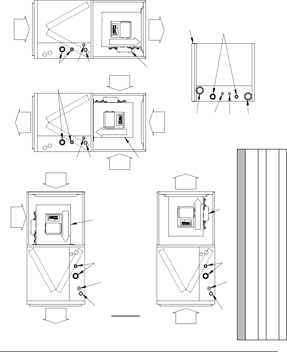
FIGURE 2B – HORIZONTAL & COUNTERFLOW DUCTING CONFIGURATIONS
Blower Air
Blower Air
Blower Air
Blower Air
Return
Remote Condenser Section
Supply
Supply
Supply
Return
Return
Return
Counterflow
Return
Main Drain
Horizontal, Left Discharge
Return
MIS-2826
Evap. Coil
Evap. Coil
Evap. Coil Evap. Coil
Position
Optional Top
Horizontal, Right Discharge
Drain
Desuper.
Secondary Drain
Position
Upflow
Drain
Main Drain
Secondary Drain
Secondary
Main Drain
Blower in
Shipped Position
Blower in
Shipped Position
Blower in
Alternate Position
Alternate Position
Blower in
Supply
Cond. Coil
Water Out
Cond. Coil
Water In
Desuper.
Water In
Water Out
Secondary
Main Drain
Refrigerant
Return
Refrigerant
Connections
Refrigerant
Connections
Connections
Refrigerant
Connections
< >
Air Filter Required on Return Air Side for All Installations
Upowinstallationscanuse(1)FR23(16x25x1)oreldsuppliedequivalentoneithersideofthe
blower section. Use of (2) on both sides is optional.
Bottomreturnforupowandtopreturnfordownowmustbeeldsupplied.
Forhorizontalatticorcrawlspaceinstallationslterarrangementmustbeeldsupplied&should
be located in readily accessible location for the user.
See additional information on Pages 19 & 20.
NOTE: Requires horizontal
drain pan kit Model GTHZ-1
Model GTLID
NOTE:
Requires Switch #4
on Tap Select Control
to be Turned On.

Manual 2100-537
I
Page 15 of 54
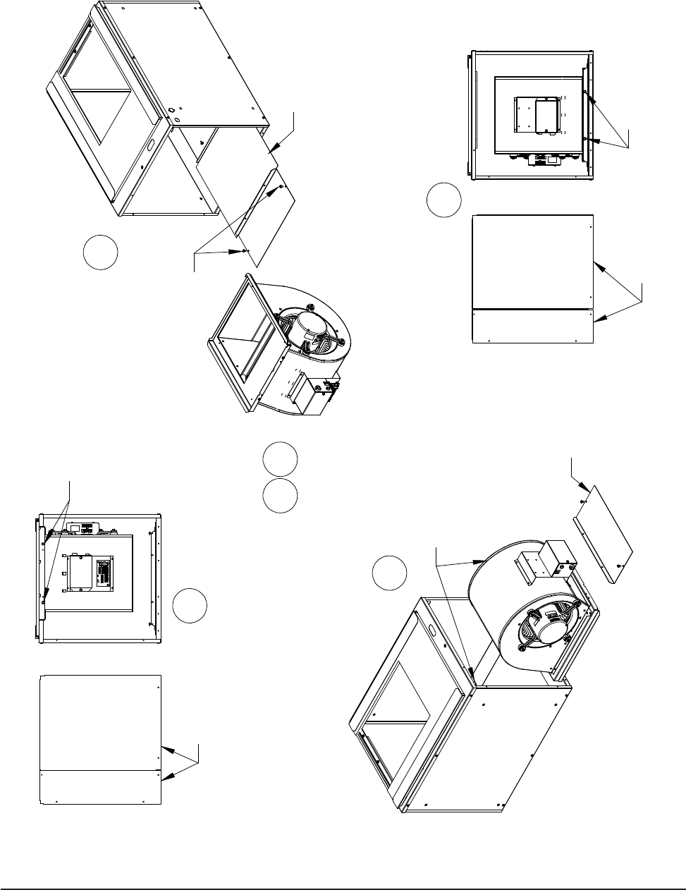
BLOWER CONVERSION FROM UPFLOW
TO COUNTERFLOW OR HORIZONTAL
RIGHT DISCHARGE
Following the directions on Figure 3 for counterow and
horizontal right discharge, the indoor blower must be
removed and turned over in its mounting conguration.
• Step 1 Remove both front service panels from the
GTB1-A.
• Step 2 Remove two screws securing blower at top
of GTB1-A (See Figure 3), and slide the
blower forward and out of the chassis.
• Step 3 Remove two screws from front ll plate on
bottom of GTB1-A, and slide both pieces of
metal forward and out of chassis.
• Step 4 Dip switch #4 on blower tap select control
must be turned “on”. (Refer to Wiring
Diagram 4117-100.)
• Step 5 While turning on tap #4 above, adjust the
other taps accordingly for the tonnage of unit
being applied. (Refer to Wiring Diagram
4117-100.)
• Step 6 Turn blower over and slide into rails of
bottom rear of the GTB1-A front ll plate
that was removed in Step 3 above.
• Step 7 Remove bottom rear ll plate from bottom
front ll plate (discard rear), and resecure
front ll plate into unit base and front of
blower.
• Step 8 Replace GTB1-A front service doors after
making line and control voltage wiring
connections.
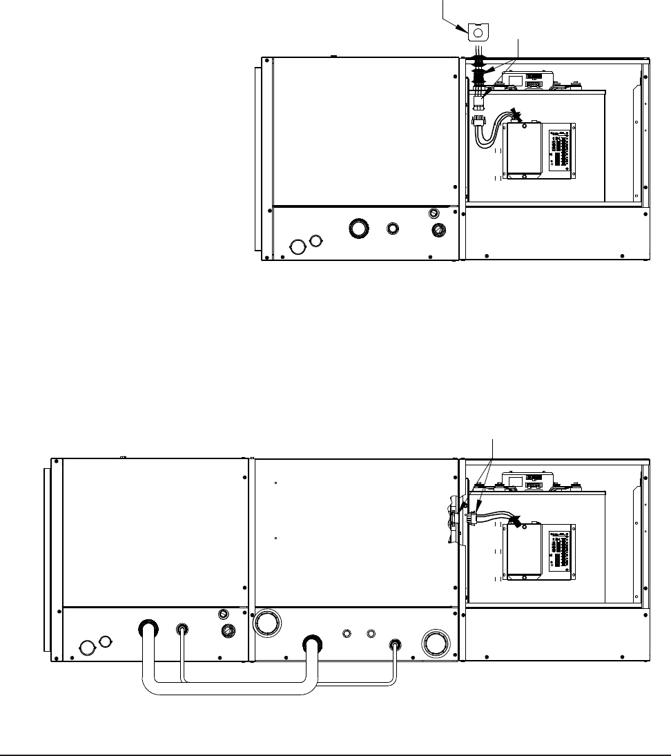
BLOWER LINE POWER CONNECTION
Power connections for the GTB1-A can be made two
different ways.
The rst is in “stacked” congurations, the blower can
be plugged into an electrical connection from the bottom
of the compressor (GTC**S2 Model Unit). This will
work for either upow or counterow applications. All
electrical sizing has been sized to accommodate this.
The second is with “remote” blower (meaning separate
from the compressor section). Supplied in the GTB1-A
is an adaptor wire harness. On the right-hand side of the
GTB1-A chassis is a ½" electrical knockout. This harness
can be installed through this knockout with the supplied
strain relief into a standard electrical junction box (eld
supplied). Electrical load sizing is included on the serial
plate of the GTB1-A for the required separate branch
circuit (See Figure 4).
Manual 2100-537
I
Page 16 of 54
FIGURE 3 – BLOWER CONFIGURATIONS
FRONT PANELS
REMOVE BOTH
REMOVE (2) SCREWS
SECURING BLOWER
AND SLIDE BLOWER
OUT OF CABINET
1
SECURING BLOWER TO
FRONT FILL PLATE
REINSTALL (2) SCREWS
REINSTALL BOTH
FRONT PANELS
5
4
6
2
REMOVE (2) SCREWS FROM
FRONT FILL PLATE AND SLIDE
BACK FILL PLATE OUT OF CABINET
DISCARD BACK
FILL PLATE
3
ROTATE BLOWER AND SLIDE
INTO BOTTOM OFFSETS
REINSTALL
FRONT FILL PLATE
MIS-2842 A
Manual 2100-537
I
Page 17 of 54
FIGURE 4 – BLOWER POWER CONNECTIONS
STACKED CONFIGURATIONS
UPFLOW AND COUNTERFLOW
CONDENSER BASE FOR BOTH
PLUG BLOWER POWER
CONNECTOR INTO POWER
PLUG PROTRUDING THROUGH
MOUNT FIELD
SUPPLIED SINGLE
GANG ELECTRICAL
BOX ALIGNED OVER
HIGH VOLTAGE K.O.
MIS-2843
REMOVE SUPPLIED
WIRE HARNESS AND
STRAIN RELIEF BUSHING
FROM BLOWER POWER PLUG.
ROUTE WIRE HARNESS
THROUGH STRAIN RELIEF
AND INTO ELECTRICAL BOX
TO MAKE FIELD POWER
CONNECTION
Manual 2100-537
I
Page 18 of 54
For installations requiring the continued use of an
existing gas or oil red furnace, add-on cased “A” coils
are available. Two 3-ton coils designed to t standard
“B” and “C” width furnaces and one 4/5 ton coil
designed for a “C” cabinet are available. Refer to Page
4 of this manual for the model nomenclature and the
specication sheet for performance data.
For top discharge oil furnaces, the coil drain pan MUST
be located a minimum of 6 inches above the top of
the furnace cabinet. Two coil spacer accessories are
available to t Bard oil furnaces:
CSADP2220 22" x 20" x 6"
All models except 140,000 Btu Low-Boy
CASDP2520 25" x 20" x 6"
140,000 Btu Low-Boy only
For all other brands, a coil support system must be eld
fabricated to maintain the 6" spacing.
APPLICATION AND LOCATION
WARNING
In applying a duct heater, refer to duct heater installation
instructions for minimum clearance to combustible materials,
maximum allowed inlet air temperatures, and minimum air
volumerequirementsforKWusage.
DUAL FUEL HEATING / COOLING
Dual fuel is the combination of a fossil fuel furnace, normally
gas or oil, with a heat pump. In milder weather the heat pump
uses the available outdoor warmth and will transport that heat
into your house cheaper than burning gas or oil. When it gets
very cold, around 35 degrees F., the heat pump automatically
shuts down and the furnace heats the home. This combination
gives you the maximum savings on both heating and cooling
while providing you with ideal indoor comfort.
Dual fuel systems are becoming increasingly popular in lieu
of conventional high efciency furnaces with air conditioning
due to the energy savings and ease of installation. Today’s
new hi-tech thermostats eliminate the need for complicated
wiring and duel fuel control boards. Bard recommends
using the Honeywell THX9321R5030 Prestige® Thermostat
(Does not include outdoor sensor). Honeywell also offers
the Prestige® Kit 2.0 which includes the THX9321R5030
Prestige® Thermostat, REM5000R1001 Portable Comfort
Control and C7089R1013 Wireless Outdoor Sensor.
LOCATION
The unit may be installed in a basement, closet, or utility room
provided adequate service access is ensured.
These units are not approved for outdoor installation
and therefore must be installed inside the structure being
conditioned. Do not locate in areas subject to freezing in the
winter or subject to sweating in the summer.
Before setting the unit, consider ease of piping, drain and
electrical connections for the unit. Also, for units which will
be used with a desuperheater unit, consider the proximity of
the unit to the water heater or storage tank. Place the unit on a
solid base, preferably concrete, to minimize undesirable noise
and vibration. DO NOT elevate the base pan on rubber or
cork vibration eliminator pads as this will permit the unit base
to act like a drum, transmitting objectionable noise.
DUCTWORK
If the unit is to be installed in a closet or utility room which
does not have a oor drain, a secondary drain pan under the
entire unit is highly recommended.
DO NOT install the unit in such a way that a direct path exists
between any return grille and the unit. Rather, insure that the
air entering the return grille will make at least one turn before
entering the unit or coil. This will reduce possible objectionable
compressor and air noise from entering the occupied space.
Design the ductwork according to methods given by the
Air Conditioning Contractors of America. When duct runs
through unconditioned spaces, it should be insulated with
vapor barrier. It is recommended that exible connections be
used to connect the ductwork to the unit in order to keep the
noise transmission to a minimum.
GENERAL
The GT Series Geothermal Heat Pumps feature three sections
(GTA - Air Coil Section, GTB - Blower Section and GTC -
Compressor Section) which cover upow (bottom, right/left-
side return), counterow and horizontal (left and right-hand
discharge) applications.
The individual sections are shipped internally wired, requiring
duct connections, thermostat wiring, 230/208 volt AC power
wiring, refrigerant line connections and water piping. The
equipment covered in this manual is to be installed by trained,
experienced service and installation technicians.
These instructions and any instructions packaged with any
separate equipment required to make up the entire heat
pump system should be carefully read before beginning the
installation. Note particularly any tags and/or labels attached
to the equipment.
While these instructions are intended as a general
recommended guide, they do not in any way supersede any
national and/or local codes. Authorities having jurisdiction
should be consulted before the installation is made.
SHIPPING DAMAGE
Upon receipt of the equipment, the carton should be checked
for external signs of shipping damage. If damage is found,
the receiving party must contact the last carrier immediately,
preferably in writing, requesting inspection by the carrier’s agent.
APPLICATION
Capacity of the unit for a proposed installation should be
based on heat loss calculations made in accordance with
methods of the Air Conditioning Contractors of America.
The air duct system should be sized and installed in
accordance with Standards of the National Fire Protection
Association for the Installation of Air Conditioning and
Venting systems of Other than Residence Type NFPA
No. 90A, and residence Type Warm Air Heating and Air
Conditioning Systems, NFPA No. 90B.
Manual 2100-537
I
Page 19 of 54
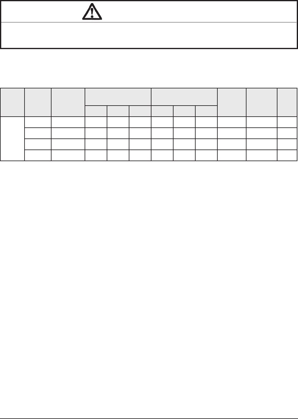
TABLE 5
ELECTRICAL HEAT SPECIFICATIONS
+ Based upon 75°C copper wire. All wiring must conform to National Electric Code (Latest Edition) and all local codes.
For Use
With Heater
Package Heater
Package
240 Volts 208 Volts Minimum
Circuit
Ampacity
Maximum
HACR
Circuit
Breaker
Field
Wire
Size
+
KW Amps BTUH KW Amps BTUH
All
GTC*S2
Models
8604-080 240/208-60-1 5.0 20.8 17,065 3.75 18.0 12,799 26.0 30 #10
8604-081 240/208-60-1 9.8 40.8 33,447 7.35 35.3 25,086 52.0 60 #6
8604-082 240/208-60-1 14.7 61.2 50,171 11.0 52.9 37,543 76.6 80 #4
8604-083 240/208-60-1 19.2 81.7 65,530 14.4 69.2 49,147 102.0 125 #1
FILTER
This unit must NOT be operated without a lter installed
on return air side of the system. Insufcient airow due
to undersized duct systems, inadequate lter size, or dirty
lters can result in nuisance tripping of the high or low
pressure controls. The ductwork and lter sizing must be
designed per ASHRAE/ACCA Guidelines.
Step #1 Refer to Table 1 (Page 4) for specic unit airow
and static application information.
Step #2 Refer to Figures 5A, 5B, 5C and 5D (Page 20) for
typical installation lter congurations for your
specic application.
Step #3 Refer to Table 6 Filter Sizing Chart (Page 19)
matching your airow and lter conguration to
determine proper lter sizing.
CONDENSATE DRAIN
Drain lines must be installed according to local plumbing
codes. It is not recommended that any condensate drain
line be connected to a sewer main.
NOTE: This drain line will contain cold water and must
be insulated to avoid droplets of water from compressor
on the pipe and dripping on nished oors or the ceiling
below the unit.
PIPING ACCESS TO UNIT
Water piping to and from the unit enters the unit cabinet on
the left side of the unit. The connection directly at the unit
is a special double o-ring tting with a retainer nut that
secures it in place. (It is the same style tting used for the
ow center connection on ground loop applications.)
NOTE: All double o-ring ttings require “hand tightening
only”. Do not use wrench or pliers as retainer nut can be
damaged with excessive force.
NOTE: Apply petroleum jelly to o-rings to prevent
damage and to aid in insertion.
Various ttings are available so you may then connect
to the unit with various materials and methods. These
methods include 1" barbed ttings (straight and 90°),
1" MPT (straight and 90°), and 1-1/4" hot fusion tting
(straight only) (see Figure 7).
CAUTION
NEVER OPERATE MORE THAN 10KW STRIP HEAT WITH GEOTHERMAL HEAT
PUMP OPERATIONAL. USE ADDITIONAL KW STRIP HEAT BEYOND 10KW ONLY IN
EMERGENCY HEAT MODE.
Manual 2100-537
I
Page 20 of 54
Filter Nominal Size Surface Area FT2 Filter Type
Airow CFM
Capability @ 300
FPM Velocity
Airow CFM
Capability @ 500
FPM Velocity
Airow CFM
Capability @ 625
FPM Velocity
10" X 20" X 1" 1.39
1" Fiberglass
Disposable
415
Not Recommended Not Recommended
12" X 20" X 1" 1.67 500
14" X 20" X 1" 1.94 580
14" X 25" X 1" 2.43 730
16" X 20" X 1" 2.22 670
16" X 25" X 1" 2.78 840
20" X 20" X 1" 2.78 840
20" X 25" X 1" 3.47 1050
24" X 24" X 1" 4.00 1200
10" X 20" X 2" 1.39
2" Std. Fiberglass
Disposable
415 700
Not Recommended
12" X 24" X 2" 2.00 600 1000
14" X 20" X 2" 1.94 580 975
14" X 25" X 2" 2.43 730 1215
16" X 20" X 2" 2.22 670 1120
16" X 25" X 2" 2.78 840 1400
20" X 20" X 2" 2.78 840 1400
20" X 25" X 2" 3.47 1050 1750
24" X 24" X 2" 4.0 1200 2000
10" X 20" X 1" 1.39
1" Pleated Filter
425 700
Not Recommended
12" X 24" X 1" 2.00 600 1000
14" X 20" X 1" 1.94 590 980
14" X 25" X 1" 2.43 730 1215
16" X 20" X 1" 2.22 670 1115
16" X 25" X 1" 2.78 840 1400
20" X 20" X 1" 2.78 840 1400
20" X 25" X 1" 3.47 1050 1740
24" X 24" X 1" 4.00 1200 2000
10" X 20" X 2" 1.39
2" Pleated Filter
425 700 870
12" X 24" X 2" 2.00 600 1000 1250
14" X 20" X 2" 1.94 590 980 1215
14" X 25" X 2" 2.43 730 1215 1520
16" X 20" X 2" 2.22 670 1115 1400
16" X 25" X 2" 2.78 840 1400 1740
20" X 20" X 2" 2.78 840 1400 1740
20" X 25" X 2" 3.47 1050 1740 2170
24" X 24" X 2" 4.00 1200 2000 2500
12" X 24" X 4" 2
4" Pleated Filter
600 1000 1250
16" X 20" X 4" 2.22 670 1115 1400
20" X 20" X 4" 2.78 840 1400 1740
20" X 25" X 4" 3.47 1050 1740 2170
24" X 24" X 4" 4 1200 2000 2500
TABLE 6
FILTER SIZING CHART
Toself-calcuateforadditionalltersizes:
Airow/NominalFilterSize(FT2) = Velocity
1600CFM/3.47(20"x25"lter)=461FPM(feetperminutevelocity)
Manual 2100-537
I
Page 21 of 54
FIGURE 5A AIR FILTER APPLICATIONS FIGURE 5B
FIGURE 5C FIGURE 5D
MIS-2881
AIR FILTER
AIRFLOW
AIRFLOW
AIRFLOW
AIR FILTER
*
*
INFORMATION.
AIR FILTER
*
*
*NOTE: SINGLE FILTER MAY REQUIRE
A TRANSITION FOR ADEQUATE FILTER
SIZING. SEE FILTER APPLICATION
AIRFLOW
AIR FILTER
(ONE OR MULTIPLE)
CENTRAL RETURN GRILLE(S)
SIDE INLET(S); ONE OR
BOTH SIDES OR IN COMBINATION
WITH BOTTOM INLET
AIR FILTER
AIR FILTER
AIR FILTER
AIR FILTER
AIR FILTER
AIR FILTER
AIRFLOW
*NOTE: SINGLE FILTER MAY REQUIRE
A TRANSITION FOR ADEQUATE FILTER
SIZING. SEE FILTER APPLICATION
INFORMATION.
*
AIRFLOW
CONFIGURATION "V" FILTER CONFIGURATION
*
AIRFLOW
"A" FILTER CONFIGURATION
AIRFLOW AIRFLOW
SINGLE FILTER
MIS-2882
AIR FILTER
CENTRAL RETURN GRILLE(S)
(ONE OR MULTIPLE)
MIS-2883
(ONE OR MULTIPLE)
CENTRAL RETURN GRILLE(S)
AIR FILTER
SIDE INLET(S); ONE OR
BOTH SIDES OR IN COMBINATION
WITH BOTTOM INLET
AIR FILTER
AIR FILTER
*
**
*
AIRFLOW
AIRFLOW
AIRFLOW
AIR FILTER
AIRFLOW
*NOTE: SINGLE FILTER MAY REQUIRE
A TRANSITION FOR ADEQUATE FILTER
SIZING. SEE FILTER APPLICATION
INFORMATION.
AIR FILTER
*
AIR FILTER
AIR FILTER
AIR FILTER
AIR FILTER
AIR FILTER
*
AIR FILTER
AIRFLOW
AIRFLOW
AIRFLOW
AIRFLOW
MIS-2884
AIRFLOW
CONFIGURATION
SINGLE FILTER
"A"/"V" FILTER
CONFIGURATION
CENTRAL RETURN
(ONE OR MULTIPLE)
INFORMATION.
*NOTE: SINGLE FILTER MAY REQUIRE
A TRANSITION FOR ADEQUATE FILTER
SIZING. SEE FILTER APPLICATION
AIRFLOW
HORIZONTAL FRONT DISCHARGE
HORIZONTAL LEFT DISCHARGE
UPFLOW COUNTERFLOW
FILTERS SHOULD ALWAYS BE APPLIED IN A MANNER THAT MAKES THEM EASY TO ACCESS & CHANGE.

Manual 2100-537
I
Page 22 of 54
WIRING INSTRUCTIONS
GENERAL
All wiring must be installed in accordance with the
National Electrical Code and local codes. In Canada, all
wiring must be installed in accordance with the Canadian
Electrical Code and in accordance with the regulations of
the authorities having jurisdiction. Power supply voltage
must conform to the voltage shown on the unit serial plate.
A wiring diagram of the unit is attached to the inside of the
electrical cover. The power supply shall be sized and fused
according to the specications supplied. A ground lug is
supplied in the control compartment for equipment ground.
The unit rating plate lists a “Maximum Time Delay Fuse”
or “HACR” type circuit breaker that is to be used with the
equipment. The correct size must be used for proper circuit
protection and also to assure that there will be no nuisance
tripping due to the momentary high starting current of the
compressor motor.
CONTROL CIRCUIT WIRING
The minimum control circuit wiring gauge needed to insure
proper operation of all controls in the unit will depend on
two factors.
1. The rated VA of the control circuit transformer.
2. The maximum total distance of the control circuit
wiring.
Table 6 should be used to determine proper gauge of control
circuit wiring required.
For low voltage connections, see Figure #6. There are
multiple options based upon the type of installation in
regards to low voltage electrical connections and what
options are selected. These options include a motorized
valve or motorized valve with end switch for ground water
applications, and optional electric duct heater connections.
NOTE: Review the “lettered triangles” and the
corresponding notes on the lower right-hand corner of
Figure #6. When options are not used, the wires will need
attached to the reference points accordingly.
Example: 1. Control Circuit transformer rated at 50 VA
2. Maximum total distance of control circuit
wiring 85 feet.
From Table 7 minimum of 16 gauge wire should be used in
the control circuit wiring.
WALL THERMOSTAT SELECTION
The wall thermostat selection is important in that it needs to
be minimally 2-stage heat and 2-stage cool for applications
without electric heat.
For applications with electric heat, the thermostat will need
to minimally be 3-stage heat and 2-stage cool. The second
bank of electric heat (when equipped) should be wired
through a secondary relay for operation only in Emergency
Heat Mode, at which point compressor operation should be
disabled.
Refer to Figure 6 on the following page for typcial
thermostat connections.
Low Voltage Connection
These units use a grounded 24-volt AC low voltage circuit
and require at least a 2-stage heating and a 2-stage cooling
thermostat.
“R” terminal is 24 VAC hot.
“C” terminal is 24 VAC grounded.
“G” terminal is the fan input.
“Y1” terminal is the compressor part load input.
“Y2” terminal is the compressor full load input.
“O” terminal is the reversing valve input. The reversing
valve must be energized for cooling mode.
“L” terminal is the check light output/compressor lockout.
This terminal is activated on high pressure switch, low
pressure switch, condensate overow, or freeze stat trip.
This is a 24 VAC output.
“W1” terminal is rst stage electric heat input. (If
equipped.)
“E” terminal is the emergency heat input. This energizes
the emergency heat relay, and should be utilized to limit
the amount of electric heat with the geothermal heat pump
operational to limit outlet air temperature.
“W2” terminal is the second stage electric heat input. (If
equipped.)
TABLE 7
CONTROL CIRCUIT WIRING
Rated VA of
Control Circuit
Transformer
Transformer
Secondary
FLA @ 24V
Maximum Total
Distance of Control
Circuit Wiring in Feet
50 2.1
20 gauge - 45
18 gauge - 60
16 gauge - 100
14 gauge - 160
12 gauge - 250
Manual 2100-537
I
Page 23 of 54
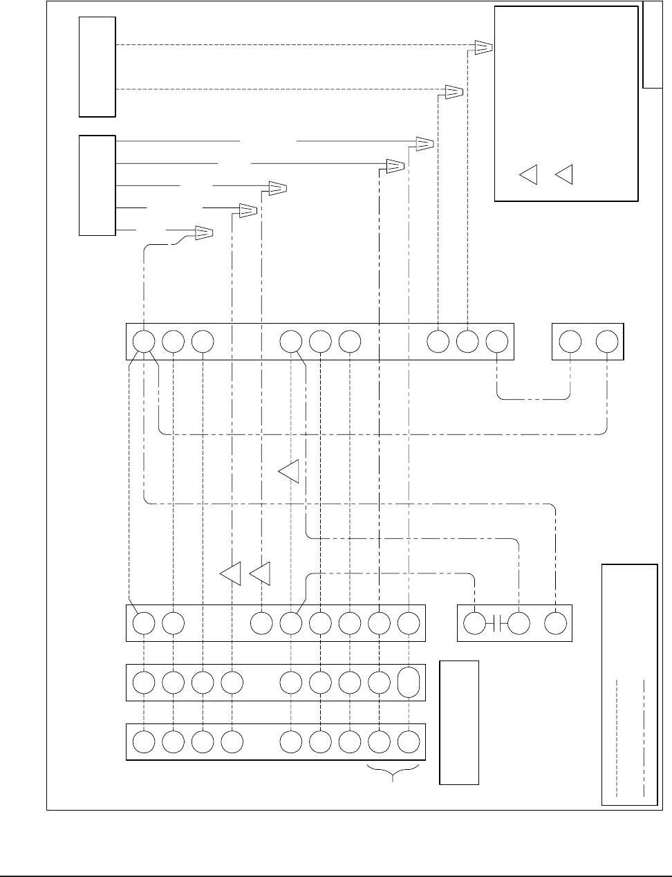
FIGURE 6
THERMOSTAT WIRING
Notes:
A
W2
Y1
NOTE: W1=FIRST STAGE AUX. HEAT
Heat Pump in GTB1-A
Y2
R
B
Y2
W2
C
W1
CO
O
CO
Y1
L
C
W1
Optional Wiring
R
Y2
G
Thermostat Tap Select Control
A
Optional Sensor
1
3
Duct Heater
8403-060
3.) Motorized valve with or without end
Water Loop)
3 Stage Heat,
2 Stage Cool
A Coil Overflow
2
Optional
Water Loop)
White/Black
White
Green
(Use With Water/
Green/Red
Motorized Valve
Without End Switch
Motorized Valve
With End Switch
(Use with Water/
Black
A
Thermostat
A
B
Low Voltage Connection Diagram
B
O/B
Y2
L
G
Y1
ground water/water loop.
Field Installed Wiring switch should be used when installing a
W2=SECOND STAGE AUX./EMERGENCY HEAT
C
R
Y1
G
L
O/B
Optional
W2
W1/E
C
R
1.) points connect when duct heater
not used.
2.) wire not used when motorized
valve with end switch is present.
NOTE: "O/B" TERMINAL
MUST BE PROGRAMMED
TO ENERGIZE IN COOLING
4117-102 C
Terminal Strip
in GTC*S2-D
Manual 2100-537
I
Page 24 of 54
NOTE: APPLY PETROLEUM JELLY
TO O-RINGS TO PREVENT DAMAGE
AND AID IN INSERTION
WATER IN
WATER OUT
GOUND LOOP
PIPE FROM GROUND LOOP
PIPE TO
BRASS ADAPTERS
NOTE: IF USED SUPPORT
WALL BRACKET
WITH A FIELD FABRICATED
1" FLEXIBLE HOSE
HOSE CLAMPS
FLOW METER
OPTIONAL VISUAL
STRAIGHT BARBED
PUMP MODULE
MIS-2827 A
GROUND LOOP
(EARTH COUPLED WATER LOOP APPLICATIONS)
FIGURE 7
CIRCULATION SYSTEM DESIGN
NOTE:
Unit shipped from factory with 75 PSIG low pressure
switch wired into control circuit and must be rewired to 55
PSIG low pressure switch for ground loop applications.
This unit is designed to work on earth coupled water loop
systems, however, these systems operate at entering water
(without antifreeze) temperature with pressures well below
the pressures normally experienced in water well systems.
THE CIRCULATION SYSTEM DESIGN
Equipment room piping design is based on years of
experience with earth coupled heat pump systems. The
design eliminates most causes of system failure.
The heat pump itself is rarely the cause. Most problems
occur because designers and installers forget that a ground
loop “earth coupled” heat pump system is NOT like a
household plumbing system.
Most household water systems have more than enough
water pressure either from the well pump of the municipal
water system to overcome the pressure of head loss in 1/2
inch or 3/4 inch household plumbing. A closed loop earth
coupled heat pump system, however, is separated from the
pressure of the household supply and relies on a small, low
wattage pump to circulate the water and antifreeze solution
through the earth coupling, heat pump and equipment room
components.
The small circulator keeps the operating costs of the system
to a minimum. However, the performance of the circulator
MUST be closely matched with the pressure of head loss
of the entire system in order to provide the required ow
through the heat pump. Insufcient ow through the heat
exchanger is one of the most common causes of system
failure. Proper system piping design and circulator selection
will eliminate this problem.

Manual 2100-537
I
Page 25 of 54
START UP PROCEDURE FOR GROUND
LOOP SYSTEM
1. Be sure main power to the unit is OFF at disconnect.
2. Set thermostat system switch to OFF, fan switch to
AUTO.
3. Move main power disconnect to ON. Except as required
for safety while servicing, DO NOT OPEN THE UNIT
DISCONNECT SWITCH.
4. Check system airow for obstructions.
A. Move thermostat fan switch to ON. Blower runs.
B. Be sure all registers and grilles are open.
C. Move thermostat fan switch to AUTO. Blowing
should stop.
5. Flush, ll and pressurize the closed loop system per
IGSHPA guidelines.
6. Fully open the manual inlet and outlet valves. Start the
loop pump module circulator(s) and check for proper
operation. If circulator(s) are not operating, turn off
power and diagnose the problem.
7. Check uid ow using a direct reading ow meter or a
single water pressure gauge, measure the pressure drop
at the pressure/temperature plugs across the water coil.
Compare the measurement with ow versus pressure
drop table to determine the actual ow rate. If the ow
rate is too low, recheck the selection of the loop pump
module model for sufcient capacity. If the module
selection is correct, there is probably trapped air or a
restriction in the piping circuit.
8. Start the unit in cooling mode by moving the thermostat
switch to cool. Fan should be set for AUTO.
9. Check the system refrigerant pressures against the
cooling refrigerant pressure table in the installation
manual for rated water ow and entering water
temperatures. If the refrigerant pressures do not match,
check for airow problem then refrigeration system
problem.
10. Switch the unit to the heating mode by moving the
thermostat switch to heat. Fan should be set for AUTO.
11. Check the refrigerant system pressures against the
heating refrigerant pressure table in installation manual.
Once again, if they do not match, check for airow
problems and then refrigeration system problems.
NOTE: If a charge problem is determined (high or low):
A. Check for possible refrigerant leaks.
B. Recover all remaining refrigerant from unit and
repair leak.
C. Evacuate unit down to 29 inches of vacuum.
D. Recharge the unit with refrigerant by weight.
This is the only way to insure a proper charge.
Manual 2100-537
I
Page 26 of 54
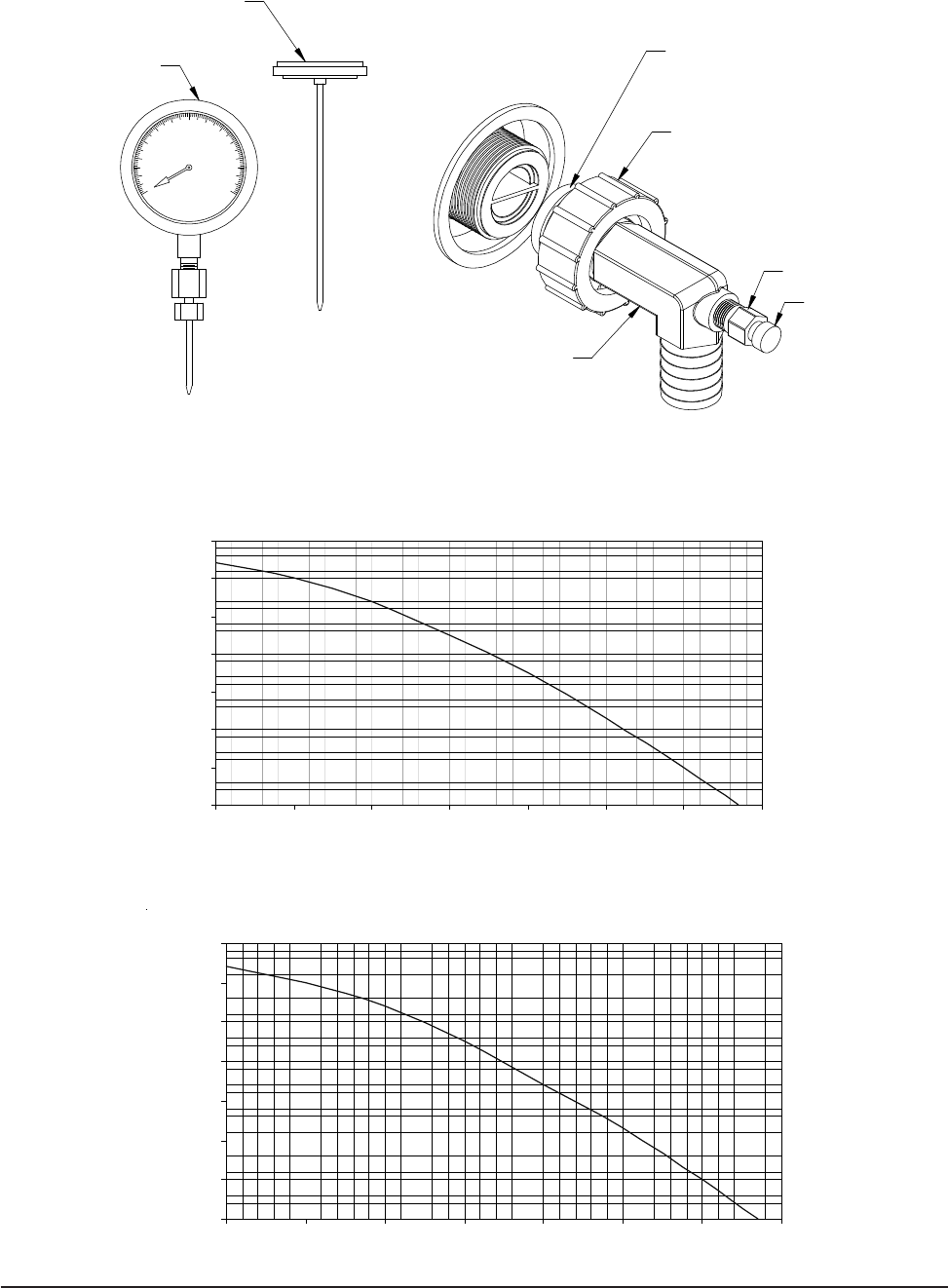
FIGURE 8
10
120
110
100
90
80
70
60
50
40
30
20
0
Retaining cap, hand tighten only
Pete's test plug
Test plug cap
Barbed 90° adapter
MIS-2622 A
NOTE: Slide retaining cap back to expose
double o-rings. Apply petroleum jelly to o-rings
to prevent damage and aid in insertion
with guage adaptor
Dial face pressure guage
Thermometer
Manual 2100-537G
Page 25 of 52
0
10
20
30
40
50
60
70
0 5 10 15 20 25 30 35
Flow (GPM)
Head (Feet)
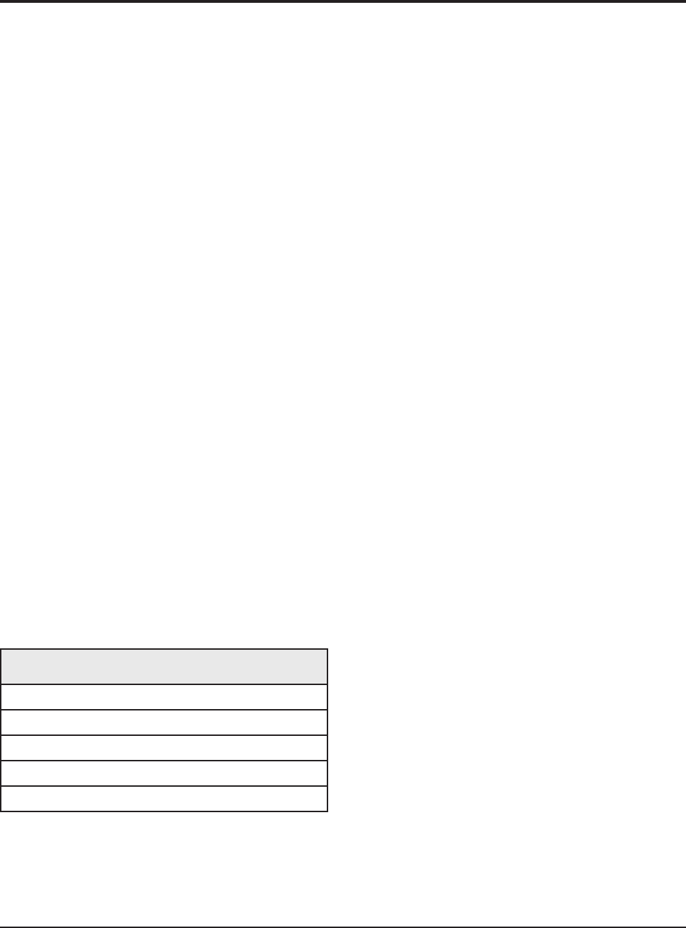
FIGURE 10
PERFORMANCE MODEL DORFC-2 FLOW CENTER
0
5
10
15
20
25
30
35
0 5 10 15 20 25 30 35
Flow (GPM)
Head (Feet)
FIGURE 9
PERFORMANCE MODEL DORFC-1 FLOW CENTER
FIGURE 8
10
120
110
100
90
80
70
60
50
40
30
20
0
Retaining cap, hand tighten only
Pete's test plug
Test plug cap
Barbed 90° adapter
MIS-2622 A
NOTE: Slide retaining cap back to expose
double o-rings. Apply petroleum jelly to o-rings
to prevent damage and aid in insertion
with guage adaptor
Dial face pressure guage
Thermometer
Manual 2100-537
I
Page 27 of 54
GROUND WATER
(WELL SYSTEM APPLICATIONS)
NOTE:
Unit shipped from factory with 60 PSIG low pressure
switch wired into control circuit for ground water
applications.
WATER CONNECTIONS
It is very important that an adequate supply of clean, non-
corrosive water at the proper pressure be provided before
the installation is made. Insufcient water, in the heating
mode for example, will cause the low pressure switch to
trip, shutting down the heat pump. In assessing the capacity
of the water system, it is advisable that the complete water
system be evaluated to prevent possible lack of water or
water pressure at various household xtures whenever the
heat pump turns on. All plumbing to and from the unit is to
be installed in accordance with local plumbing codes. The
use of plastic pipe, where permissible, is recommended to
prevent electrolytic corrosion of the water pipe. Because
of the relatively cold temperatures encountered with well
water, it is strongly recommended that the water lines
connecting the unit be insulated to prevent water droplets
from condensing on the pipe surface.
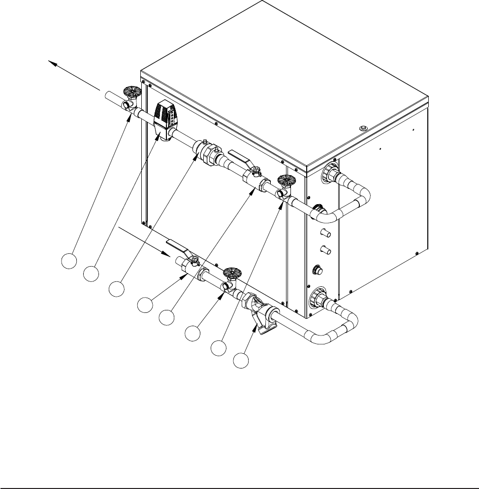
Refer to piping, Figure 11. Slow open/close with End
Switch (2), 24V, provides on/off control of the water ow to
the unit. Refer to the wiring diagram for correct hookup of
the valve solenoid coil.
Constant Flow Valve (3) provides correct ow of water to
the unit regardless of variations in water pressure. Observe
the water ow direction indicated by the arrow on the side
of the valve body. Following is a table showing which
valve is to be installed with which heat pump.
Strainer (8) installed upstream of water coil inlet to collect
foreign material which would clog the ow valve orice.
The gure shows the use of shutoff valves (4) and (5), on
the in and out water lines to permit isolation of the unit from
the plumbing system should future service work require this.
Globe valves should not be used as shutoff valves because
of the excessive pressure drop inherent in the valve design.
Instead use gate or ball valves as shutoffs, so as to minimize
pressure drop.
Hose bib (6) and (7), and tees should be included to permit
acid cleaning the refrigerant-to-water coil should such
cleaning be required. See WATER CORROSION.
Hose bib (1) provides access to the system to check water
ow through the constant ow valve to insure adequate
water ow through the unit. A water meter is used to check
the water ow rate.
WELL PUMP SIZING
Strictly speaking, sizing the well pump is the responsibility
of the well drilling contractor. It is important, however,
that the HVAC contractor be familiar with the factors that
determine what size pump will be required. Rule of thumb
estimates will invariably lead to under or oversized well
pumps. Undersizing the pump will result in inadequate
water to the whole plumbing system, but with especially bad
results to the heat pump – NO HEAT / NO COOL calls will
result. Oversized pumps will short cycle and could cause
premature pump motor or switch failures.
The well pump must be capable of supplying enough water
and at an adequate pressure to meet competing demands of
water xtures. The well pump must be sized in such a way
that three requirements are met:
1. Adequate ow rate in GPM.
2. Adequate pressure at the xture.
3. Able to meet the above from the depth of the
well-feet of lift.
TABLE 8
CONSTANT FLOW VALVES
(1)
Thepressuredropthroughtheconstantowvalvewill
vary depending on the available pressure ahead of the valve.
Unless minimum of 15 psig is available immediately ahead
ofthevalve,nowaterwillow.
Part No. Min. Available
Pressure PSIG Flow Rate
GPM
CFV-5 15 (1) 5
CFV-6 15 (1) 6
CFV-7 15 (1) 7
CFV-9 15 (1) 9
CFV-10 15 (1) 10
Manual 2100-537
I
Page 28 of 54
2
3
45
7
6
1
8
MIS-2825
FIGURE 11
WATER CONNECTION COMPONENTS
The pressure requirements put on the pump are directly
affected by the diameter of pipe being used, as well as,
by the water ow rate through the pipe. The worksheet
included in Manual 2100-078 should guarantee that the
well pump has enough capacity. It should also ensure that
the piping is not undersized, which would create too much
pressure due to friction loss. High pressure losses due to
undersized pipe will reduce efciency and require larger
pumps and could also create water noise problems.
See descriptions for these reference numbers on Page 27.
NOTE:
Shown with Optional Top Kit for
Remote Condenser Applications

Manual 2100-537
I
Page 29 of 54
SYSTEM START UP PROCEDURE FOR
GROUND WATER APPLICATIONS
1. Be sure main power to the unit is OFF at disconnect.
2. Set thermostat system switch to OFF, fan switch to
AUTO.
3. Move main power disconnect to ON. Except as required
for safety while servicing – DO NOT OPEN THE UNIT
DISCONNECT SWITCH.
4. Check system airow for obstructions.
A. Move thermostat fan switch to ON. Blower runs.
B. Be sure all registers and grilles are open.
C. Move thermostat fan switch to AUTO. Blower
should stop.
5. Fully open the manual inlet and outlet valves.
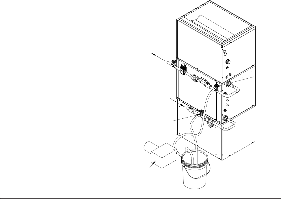
6. Check water ow.
A. Connect a water ow meter to the drain cock
between the constant ow valve and the
solenoid valve. Run a hose from the ow meter
to a drain or sink. Open the drain cock.
B. Check the water ow rate through constant
ow valve to be sure it is the same as the unit
is rated for. (Example: 6 GPM for a GTC36S2.)
C. When water ow is okay, close drain cock and
remove the water ow meter. The unit is now
ready to start.
7. Start the unit in cooling mode by moving the thermostat
switch to cool. Fan should be set for AUTO.
A. Check to see the solenoid valve opened.
8. Check the system refrigerant pressures against the cooling
refrigerant pressure table in the installation manual for
rated water ow and entering water temperatures. If
the refrigerant pressures do not match, check for airow
problem and then refrigeration system problem.
9. Switch the unit to the heat mode by moving the
thermostat switch to heat. Fan should be set for AUTO.
A. Check to see the solenoid valve opened again.
10. Check the refrigerant system pressures against the heating
refrigerant pressure table in installation manual. Once
again, if they do not match, check for airow problems
and then refrigeration system problems.
NOTE: If a charge problem is determined (high or low):
A. Check for possible refrigerant loss.
B. Discharge all remaining refrigerant from unit.
C. Evacuate unit down to 29 inches of vacuum.
D. Recharge the unit with refrigerant by weight.
This is the only way to insure proper charge.
WATER CORROSION
Two concerns will immediately come to light when
considering a water source heat pump, whether for ground
water or for a ground loop application: Will there be
enough water? And, how will the water quality affect the
system?
Water quantity is an important consideration and one which
is easily determined. The well driller must perform a pump
down test on the well according to methods described by
the National Well Water Association. This test, if performed
correctly, will provide information on the rate of ow and
on the capacity of the well. It is important to consider the
overall capacity of the well when thinking about a water
source heat pump because the heat pump may be required to
run for extended periods of time.
The second concern, about water quality, is equally
important. Generally speaking, if the water is not offensive
for drinking purposes, it should pose no problem for
the heat pump. The well driller or local water softening
company can perform tests which will determine the
chemical properties of the well water.
Water quality problems will show up in the heat pump in
one or more of the following ways:
1. Decrease in water ow through the unit.
2. Decreased heat transfer of the water coil (entering to
leaving water temperature difference is less).
There are four main water quality problems associated with
ground water. These are:
1. Biological Growth. This is the growth of microscopic
organisms in the water and will show up as a slimy
deposit throughout the water system. Shock treatment
of the well is usually required and this is best left up
to the well driller. The treatment consists of injecting
chlorine into the well casing and ushing the system
until all growth is removed.
2. Suspended Particles in the Water. Filtering will
usually remove most suspended particles (ne sand,
small gravel) from the water. The problem with
suspended particles in the water is that it will erode
metal parts, pumps, heat transfer coils, etc. So long
as the lter is cleaned and periodically maintained,
suspended particles should pose no serious problem.
Consult with your well driller.
3. Corrosion of Metal. Corrosion of metal parts results
from either highly corrosive water (acid water, generally
not the case with ground water) or galvanic reaction
between dissimilar metals in the presence of water. By
using plastic plumbing or dielectric unions, galvanic
reaction is eliminated. The use of corrosion resistant
materials such as the Cupronickel coil through the water
system will reduce corrosion problems signicantly.
Manual 2100-537
I
Page 30 of 54
FIGURE 12
CLEANING WATER COIL
MIS-2836
PUMP
HOSE BIB (A)
HOSE BIB (B)
4. Scale Formation. Of all the water problems, the
formation of scale by ground water is by far the most
common. Usually this scale is due to the formation of
calcium carbonate but magnesium carbonate or calcium
sulfate may also be present. Carbon dioxide gas (CO2),
the carbonate of calcium and magnesium carbonate,
is very soluble in water. It will remain dissolved in
the water until some outside factor upsets the balance.
This outside inuence may be a large change in water
temperature or pressure. When this happens, enough
carbon dioxide gas combines with dissolved calcium or
magnesium in the water and falls out of solution until a
new balance is reached. The change in temperature that
this heat pump produces is usually not high enough to
cause the dissolved gas to fall out of solution. Likewise,
if pressure drops are kept to a reasonable level, no
precipitation of carbon dioxide should occur.
REMEDIES OF WATER PROBLEMS
Water Treatment. Water treatment can usually be
economically justied for water loop systems. However,
because of the large amounts of water involved with a
ground water system, water treatment is generally too
expensive.
Acid Cleaning the Water Coil or Heat Pump Recovery
Unit. If scaling of the coil is strongly suspected, the coil
can be cleaned up with a solution of Phosphoric Acid (food
grade acid). Follow the manufacturer’s directions for
mixing, use, etc. Refer to the “Cleaning Water Coil”, Figure
12. The acid solution can be introduced into the heat pump
coil through the hose bib A. Be sure the isolation valves are
closed to prevent contamination of the rest of the system by
the coil. The acid should be pumped from a bucket into the
hose bib and returned to the bucket through the other hose
bib B. Follow the manufacturer’s directions for the product
used as to how long the solution is to be circulated, but it is
usually circulated for a period of several hours.
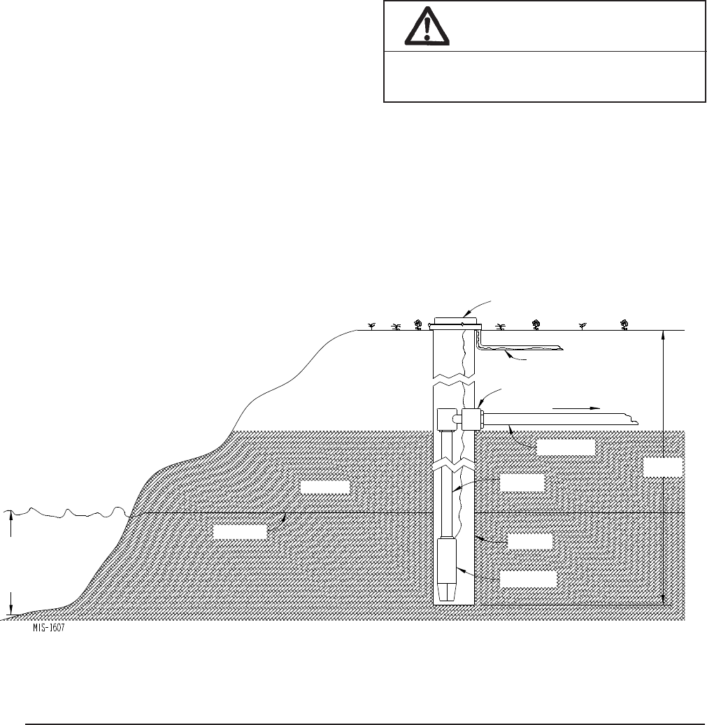
LAKE AND POND INSTALLATIONS
Lakes and ponds can provide a low cost source of water
for heating and cooling with a ground water heat pump.
Direct usage of the water without some ltration is not
recommended as algae and turbid water can foul the water to
refrigerant heat exchanger. Instead, there have been very
good results using a dry well dug next to the water line
or edge. Normal procedure in installing a dry well is to
backhoe a 15 to 20 foot hole adjacent to the body of water
(set backhoe as close to the water’s edge as possible). Once
excavated, a perforated plastic casing should be installed
with gravel backll placed around the casing. The gravel
bed should provide adequate ltration of the water to allow
good performance of the ground water heat pump.
The following is a list of recommendations to follow when
installing this type of system:
A. A lake or pond should be at least 1 acre (40,000 square
feet) in surface area for each 50,000 BTUs of ground
water heat pump capacity or have 2 times the cubic feet
size of the dwelling that you are trying to heat (includes
basement if heated).
B. The average water depth should be at least 4 feet and
there should be an area where the water depth is at least
12 to 15 feet deep.
Manual 2100-537
I
Page 31 of 54
FIGURE 13
LAKE OR POND INSTALLATION
C. If possible, use a submersible pump suspended in the
dry well casing. Jet pumps and other types of suction
pumps normally consume more electrical energy than
similarly sized submersible pumps. Pipe the unit the
same as a water well system.
D. Size the pump to provide necessary GPM for the ground
water heat pump. A 12 GPM or greater water ow rate
is required on all models when used on this type system.
E. A pressure tank should be installed in dwelling to be
heated adjacent to the ground water heat pump. A
pressure switch should be installed at the tank for pump
control.
F. All plumbing should be carefully sized to compensate
for friction losses, etc., particularly if the pond or lake is
over 200 feet from the dwelling to be heated or cooled.
G. Keep all water lines below low water level and below
the frost line.
H. Most installers use 4-inch eld tile (rigid plastic or
corrugated) for water return to the lake or pond.
I. The drain line discharge should be located at least 100
feet from the dry well location.
J. The drain line should be installed with a slope of 2
inches per 10 feet of run to provide complete drainage
of the line when the ground water heat pump is not
operating. This gradient should also help prevent
freezing of the discharge where the pipe terminates
above the frost line.
K. Locate the discharge high enough above high water
level so the water will not back up and freeze inside the
drain pipe.
L. Where the local conditions prevent the use of a gravity
drainage system to a lake or pond, you can instead run
standard plastic piping out into the pond below the frost
and low water level.
For complete information on water well systems and lake
and pond applications, refer to Manual 2100-078 available
from your distributor.
WELL CAP
ELECTRICAL LINE
PITLESS ADAPTER
WATER
SUPPLY LINE
DROP
PIPE
GRAVEL FILL
WATER LEVEL PERFORATED
PLASTIC CASING
SUBMERSIBLE
PUMP
12’
to
15’
LAKE
or
POND
TO PRESSURE
TANK
15’ to 20’
DEEP
WARNING
Thin ice may result in the vicinity of the
discharge line.
Manual 2100-537
I
Page 32 of 54
DESCRIPTION
The system is designed to heat domestic water using heat
recovered from a water source unit’s hot discharge gas.
LOCATION
Because of potential damage from freezing or condensation,
the unit must be located in a conditioned space, therefore the
unit must be installed indoors.
Locate the storage tank as close to the geothermal heat
pump and pump module as the installation permits. Keep
in mind that water lines should be a maximum of 25 feet
long measured one way. Also, the vertical lift should not
exceed 20 feet. This is to keep pressure and heat losses to a
minimum.
ELECTRICAL CONNECTION
The Desuperheater:
The desuperheater logic control with the remote thermal
sensors are built already hard-wired into the unit control
panel. 208/230-60-1 power for the desuperheater pump is
supplied with the same power as the compressor. The 24
volt signals needed are also tied in with the compressor call
signals.
INSTALLATION PROCEDURE –
GENERAL
Before beginning the installation, turn off all power supplies
to the water heater and unit, and shut off the main water
supply line.
TWO TANK – In order to realize the maximum energy
savings from the heat recovery system, it is recommended
that a second water storage tank be installed in addition to
the main hot water heater. Fossil fuel red water heaters
must be a two-tank installation.
Tanks specically intended for hot water storage are
available from water heater manufacturers (solar hot water
storage tanks). A well insulated electric water heater
without the electric heating elements will also make a
suitable storage tank.
The size of storage tank should be as large as space and
economy permit but in no event should it be less than one-
half of the daily water requirements for the occupants. As a
guide in estimating the daily family water requirements, The
Department of Energy recommends a gure of 16.07 gallons
of hot water per day per individual. For example, a family
of four would require 64.3 gallons per day (4 x 16.07).
ONE TANK – The single hot water tank may be a new hot
water heater (sized to 100% of daily water requirements) or
the existing water heater in the case of a retrot installation.
The existing water heater should be drained and ushed to
remove all loose sediment. This sediment could damage the
circulating pump. The bottom heating element should be
disconnected.
NOTE: Make sure water heater thermostats are set below
125° on One Tank Unit.
WATER PIPING – All water piping must adhere to all state
and local codes. Refer to piping diagrams for recommended
one and two tank installations. Piping connections are 1/2
inch nominal copper plumbing.
A cleanable “Y” type strainer should also be included to
collect any sediment.
DESUPERHEATER
WARNING
Never alter or plug factory installed pressure
relief valve on water heater or auxiliary tank.

Manual 2100-537
I
Page 33 of 54
DESUPERHEATER
OPERATION OF THE HEAT RECOVERY
UNIT
The pump module is a very simple device containing basic
controls and a circulating pump. Heat is transferred from
the hot refrigerant (discharge gas) to the cool water.
The operation of the Desuperheater Pump Module is
controlled rst by the operation of the Geothermal Heat
Pump and secondly by internal controls within the Pump
Module. A low voltage signal from Thermostat “Y” is
connected to the desuperheater control board and acts as the
primary on/off switch for the circulating pump.
Also connected to this board is a temperature overlimit
device which shuts down the desuperheater once inlet
water has exceeded 125° so the water cannot create a scald
condition.
There are also two (2) thermistor sensors connected to
the control board. These thermistors are measuring and
controlling to ensure there is a positive heat differential
across the water being circulated. When operating in Part
Load Condition, there are certain conditions (Ground Loop
Temperatures versus Hot Water Temperatures) that potential
exists where heat could transfer from the hot water into
the refrigeration system instead of the refrigeration system
into the hot water. Through the control board logic, these
thermistors ensure there is at least 2° positive differential
between entering/leaving water temperatures and will shut
down the pump accordingly.
START UP AND CHECK OUT
Be sure all shut off valves are open and all power supplies
are on. Open a hot water faucet to permit any air to bleed
from the plumbing.
NOTE: The inherent design of this pump for maximum
efciency means this pump is not self-priming. It is
imperative to check that the air has been adequately bled
from the system. There is a bleed-port built into the pump
module that can be utilized after the system water has been
fully restored. The bleed port is located directly above the
pump in the GTC compressor unit.
Turn ON the air conditioning system and verify the
circulating pump will operate. Feel the “Water to Unit” and
“Water from Water Heater” tubes for noticeable difference
in temperature. Turn OFF the system and verify that the
circulating pump stops.
NOTE: When checking the refrigerant operating pressures
of the ground source heat pump. The desuperheater
must be turned off. With the desuperheater operating a
wide variance in pressures can result, giving the service
technician the indication there is a charge problem when the
unit is operating correctly.
MAINTENANCE
CLEANING THE HEAT EXCHANGER – If scaling of
the coil is strongly suspected, the coil can be cleaned with
a solution of phosphoric acid (food grade acid). Follow the
manufacturer’s directions for the proper mixing and use of
cleaning agent.
Manual 2100-537
I
Page 34 of 54
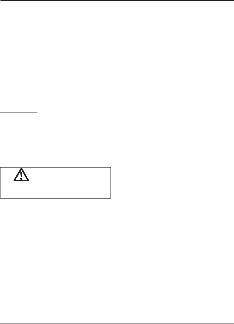
FIGURE 14
WIRING DIAGRAM
NC
LINEVOLTAGE
WATER SENSORS
TSTAT
3AMP
FUSE
POWER PUMPOUTLET
N L
OVERTEMP.LIMIT
OUTLET INLET
Y
R C
24VAC L N
CONTROL
LOGIC
NO C
21 3
MIS-2844
C
PUMP CONTROL
BLACK
BLACK
FROM GEOTHERMAL LOGIC CONTROL
RED
RED
BLACK
RED
RED
DESUPERHEATER
COMPRESSOR CONTACTOR SIGNAL
LIMIT
TEMPERATURE
MOTOR
RED
BLACK
THERMISTOR
THERMISTOR
BLACK
BLACK
208/230-60-1
LINE POWER
PUMP
BLACK
R
BI-METAL
DESUPERHEATER
PUMP PLUG
GTC LOW VOLTAGE
TERMINAL STRIP
Manual 2100-537
I
Page 35 of 54
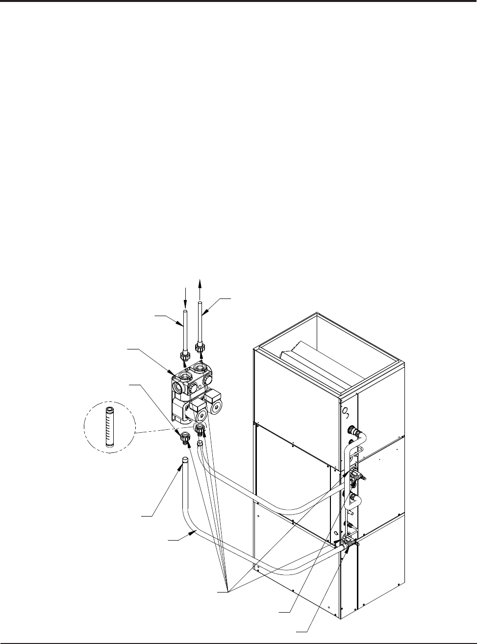
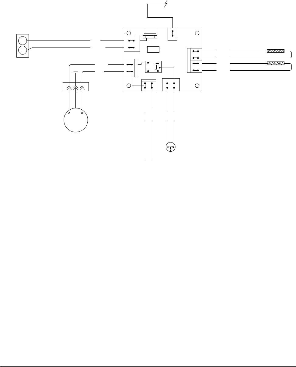
FIGURE 15A – DESUPERHEATER SINGLE TANK SYSTEM
DESUPERHEATER PUMP
SHIPPED DISCONNECTED
FROM FACTORY, CONNECT
3 PIN POWER PLUG TO
CONTROL PANEL
EXISTING WATER HEATER
L.P., GAS, OIL, ELECTRIC
WATER HEATER FACTORY
INSTALLED HIGH PRESSURE
RELIEF VALVE
HIGH PRESSURE
RELIEF VALVE
HOT WATER
TO HOUSE
COLD WATER IN
STRAINER
DRAIN
SHUTOFF
VALVES
OUT
IN
OUT
IN
WATER SOURCE UNIT
NOTES: DO NOT OPERATE PUMP WITHOUT WATER LINES
CONNECTED AND WATER IN SYSTEM WITH SHUT OFF
VALVES OPEN.
ALL PLUMBING MUST CONFORM TO LOCAL CODES
WHEN WATER STORAGE IS INSTALLED IN VERTICAL
POSITION, PIPING TO "IN" SIDE OF PUMP MUST BE
INSTALLED AT BOTTOM AS SHOWN.
OPTIONAL
CHECK VALVE
(PER CODES)
MIS-2831
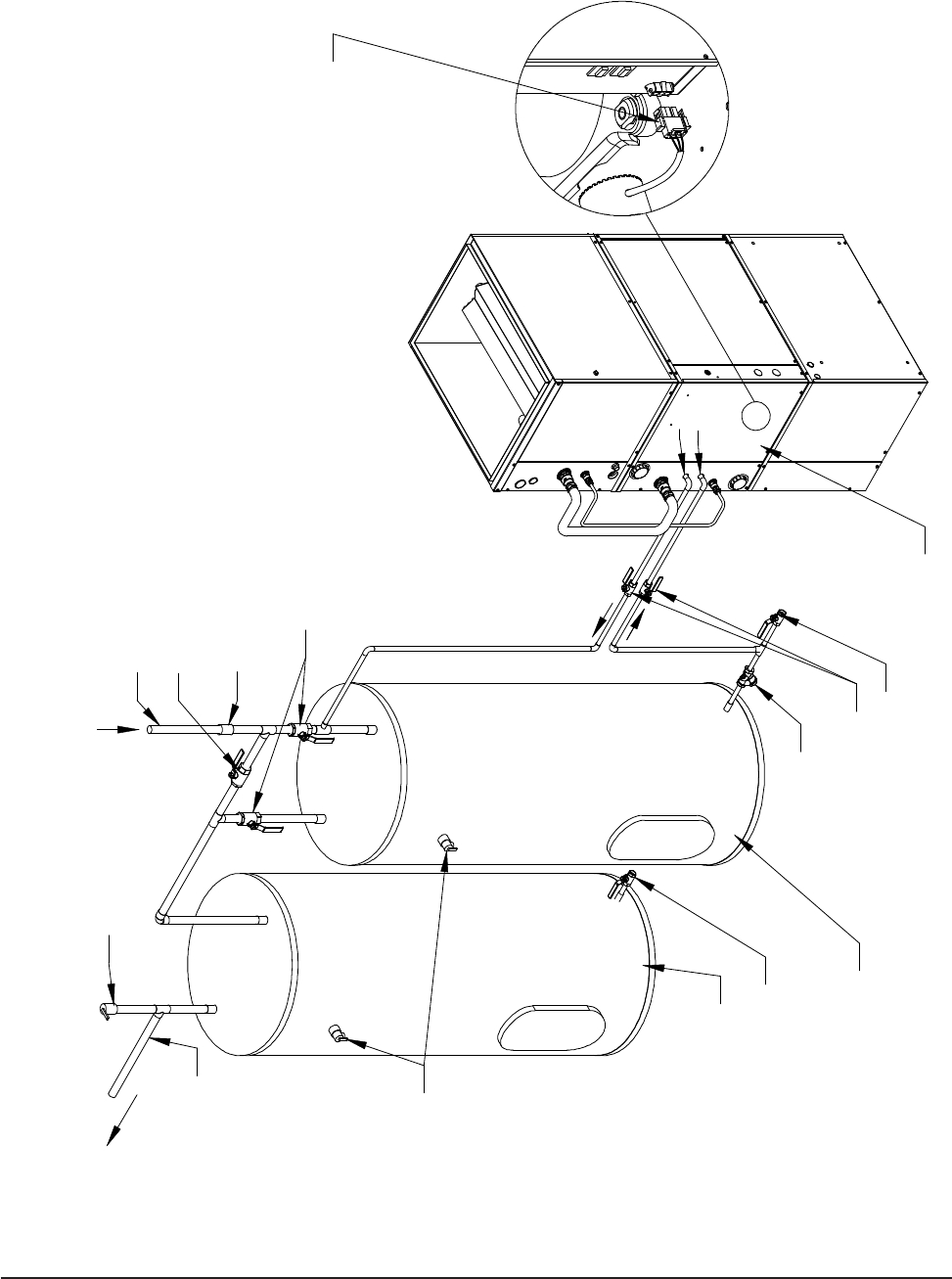
Manual 2100-537
I
Page 36 of 54
FIGURE 15B – DESUPERHEATER DUAL TANK SYSTEM
SHUTOFF VALVES
DRAIN
L.P., GAS, OIL, ELECTRIC
EXISTING WATER HEATER
RELIEF VALVE
HIGH PRESSURE
TO HOUSE
COLD WATER IN
STRAINER
RELIEF VALVES
HIGH PRESSURE
DRAIN
HOT WATER
OUT
IN
OUT
IN
WATER SOURCE UNIT
VALVES
SHUTOFF
FACTORY INSTALLED
WATER HEATER
WHEN WATER STORAGE IS INSTALLED IN VERTICAL
ALL PLUMBING MUST CONFORM TO LOCAL CODES
INSTALLED AT BOTTOM AS SHOWN.
POSITION, PIPING TO "IN" SIDE OF PUMP MUST BE
MIS-2832
OUT
(PER CODES)
CHECK VALVE
IN OPTIONAL
BYPASS LOOP
OPTIONAL
NOTES: DO NOT OPERATE PUMP WITHOUT WATER LINES
CONNECTED AND WATER IN SYSTEM WITH SHUT OFF
VALVES OPEN.
ADDITIONAL HOT WATER
STORAGE TANK. NOT
ELECTRICALLY CONNECTED
DESUPERHEATER PUMP
SHIPPED DISCONNECTED
FROM FACTORY, CONNECT
3 PIN POWER PLUG TO
CONTROL PANEL

Manual 2100-537
I
Page 37 of 54
F R F R
53.0
52.0
53.0
54.0
55.0
56.0
57.0
58.0
59.0
60.0
61.0
62.0
63.0
64.0
65.0
66.0
67.0
68.0
69.0
70.0
71.0
72.0
73.0
74.0
75.0
76.0
77.0
78.0
79.0
80.0
81.0
82.0
83.0
84.0
85.0
86.0
87.0
88.0
19374
18867
18375
17989
17434
16984
16547
16122
15710
15310
14921
14544
14177
13820
13474
13137
12810
12492
12183
11883
11591
11307
11031
10762
10501
10247
10000
9760
9526
9299
9077
8862
8653
8449
8250
8057
7869
7686
89.0
90.0
91.0
92.0
93.0
94.0
95.0
96.0
97.0
98.0
99.0
100.0
101.0
102.0
103.0
104.0
105.0
106.0
107.0
108.0
109.0
110.0
111.0
112.0
113.0
114.0
115.0
116.0
117.0
118.0
119.0
120.0
121.0
122.0
123.0
124.0
7507
7334
7165
7000
6840
6683
6531
6383
6239
6098
5961
5827
5697
5570
5446
5326
5208
5094
4982
4873
4767
4663
4562
4464
4367
4274
4182
4093
4006
3921
3838
3757
3678
3601
3526
3452
DESUPERHEATER CONTROL BOARD
SEQUENCE OF OPERATION
The desuperheating control board will make a
determination whether or not to energize the pump
relay inclusive on the control board.
A. It will constantly monitor inputs from two
temperature sensors, Inlet & Outlet water sensors.
B. It will constantly monitor the Y signal.
C. Upon acknowledgment of Y signal, and following
two minutes, the control board will energize the
pump relay.
D. After 1½ minutes, based on temperature difference
between Outlet & Inlet sensors, and the presence of
Y signal, the following will take place:
TEMPERATURE F VS RESISTANCE R OF TEMPERATURE SENSOR
1.) If temperature difference is greater than 3°F,
then the control will continue to energize pump
relay.
2.) If temperature difference is less than 3°F, then
the control will de-energize the pump relay.
3.) The control will next wait for 10 minutes
before repeating Step #1 (above).
E. The Over Temperature Limit Switch is placed in
series with the line voltage. Therefore, continuity
between L of line voltage and L of pump output is
forced broken when the Over Temperature Limit
Switch opens (see Wiring Diagram).
F. The 3-amp fuse is put in series with the R
connection to the board. Whenever the fuse
is blown, the control will lose power and
consequently, the relay will disengage.
Figure 16 — THERMISTOR

Manual 2100-537
I
Page 38 of 54
BLOWER
Blower functions are all controlled through 24 VAC input
signals from the control thermostat and 208/230 VAC being
supplied to the motor continuously.
The installer must be sure to congure the tap select control
board (located in blower compartment) based upon the
specic model application. By default, the tap select control
(located in the blower compartment), is shipped from the
factory to operate at the airow ranges for the GTC60S2
model. Please see Wiring Diagram (Page 53) which details
the required dip switch changes required between models.
NOTE 1: On a call from only “G” from the thermostat (call
for manual fan), the blower will operate at a signicantly
reduced airow rate to allow for air circulation and
ltration, but at reduced power consumption and sound
levels.
NOTE 2: There are ±10% adjustments that are enabled
on the tap select control that will allow you to increase or
decrease the air volume plus or minus 10%. Increasing the
air volume may help with some slightly increased capacity
and increased duct velocity if there is an air distribution
issue. Decreasing the air volume with help improve latent
capacity in a humid application, and will help to lower air
distribution sound levels. Please see Wiring Diagram (Page
53) which details the required dip switch changes for this
adjustment.
PART LOAD COOLING
When thermostat system switch is placed in COOL,
it completes a circuit from “R” to “O”, energizing the
reversing valve solenoid. On a call for cooling, the
thermostat completes a circuit from “R” to “Y1” sending the
signal to both the Tap Select Control located in the blower
section and to the Geothermal Logic Control located in the
compressor section. The tap select control uses the input
signal versus the motor program, and the dip switch settings
to determine the proper air volume rate to operate. The
Geothermal Logic Control veries that the High Pressure
Switch, the Low Pressure Switch, and the Freeze Stat
controls are all in the “closed” position. It then energizes
the “A” terminal ouput to start the ow center (Ground
Loop Applications) or energizes the water solenoid (Ground
Water/Water Loop Applications). Following 10 seconds of
the “A” terminal energization, the compressor contactor is
energized.
FULL LOAD COOLING
The system should already be in Part Load Cooling
operation prior to Full Load Cooling being energized.
Additionally what happens, the thermostat completes a
circuit from “R” to “Y2”. This sends a signal to both the
staging solenoid on the side of the compressor, and sends
a signal to the Blower Tap Select Control in the blower
compartment to drive the blower to the proper CFM.
PART LOAD HEATING (No Electric Heat)
When thermostat system is placed in HEAT, the reversing
valve solenoid is no longer energized. On a call for part
load heating, the thermostat completes a call from “R” to
“Y1” sending the signal to both the Tap Select Control
located in the blower compartment, and to the Geothermal
Logic Control located in the compressor section. The
tap select control uses the input signal versus the motor
program, and the dip switch settings to determine the proper
air volume rate to operate. The Geothermal Logic Control
veries that the High Pressure Switch, the Low Pressure
Switch, and the Freeze Stat controls are all in the “closed”
position. It then energizes the “A” terminal output to start
the ow center (Ground Loop Applications) or energizes the
water solenoid (Ground Water/Water Loop Applications.)
Following 10 seconds of the “A” terminal energization, the
compressor contactor is energized.
FULL LOAD HEATING
The system should already be in Part Load Heating
operation prior to Full Load Heating being energized.
Additionally what happens, the thermostat completes a
circuit from “R” to “Y2”. This sends a signal to both the
staging solenoid on the side of the compressor, and sends
a signal to the Blower Tap Select Control in the blower
compartment to drive the blower to the proper CFM.
SUPPLEMENTARY ELECTRIC HEAT
The system should already be in FULL LOAD HEATING
operation (above). The thermostat completes a circuit from
“R” to “W2”, which energizes the rst bank of electric heat.
GEOTHERMAL LOGIC CONTROL
If the controller operates in normal mode, the green Status
LED blinks. This indicates that 24 volt power is applied to
the board and the controller is running in normal operation.
On initial power up and call for compressor operation, a
5-minute delay + a random start delay of 0 to 60-second
is applied. After the random delay, the compressor relay
is energized (Terminals CC & CCG). When the “Y” input
opens the compressor de-energizes.
Water Solenoid – When “Y” signal is sent to Geothermal
Logic Control, the water solenoid output “A” terminal
will energize 10 seconds prior to “CC” output that starts
compressor.
Anti-Short Cycle Timer – After compressor shutdown, or
power disruption, a 5-minute timer is applied and prevents
the compressor from operating.
SEQUENCE OF OPERATION

Manual 2100-537
I
Page 39 of 54
HIGH PRESSURE SWITCH
(TERMINALS HP1 & HP2) Circuit will be proved as
“closed” prior to energizing “A” or “CC” terminals. If
pressure switch opens, compressor will go into soft lockout
mode and compressor operation will be terminated; green
fault light illuminated. Logic control will then go through
5-minute delay on break + random start sequence. If no
fault found on next run cycle, compressor will continue
operation. If fault reoccurs, hard lockout occurs, and fault
signal is sent to “L” terminal.
LOW PRESSURE SWITCH
(TERMINALS LP1 & LP2) Circuit will be proved as
“closed” prior to energizing “A” or “CC” terminals. The
conditions of the LP terminals will then be ignored for the
rst 90 seconds after a demand for compressor operation.
Following this 90 second period, if pressure switch opens,
compressor will go into soft lockout mode and compressor
operation will be terminated; orange fault light illuminated.
The control board will then go through a 5-minute delay
on break + random start sequence. If no fault found on
next run cycle, compressor will continue operation. If fault
reoccurs, hard lockout occurs, and fault signal is sent to “L”
terminal.
FREEZE STAT (Optional Field Add-On
Option)
(TERMINALS FS & FS2) Circuit will be proved as
“closed” prior to energizing “A” or “CC” terminals. If
freezestat switch opens, compressor will go into soft lockout
mode and compressor operation will be terminated; red
fault light illuminated. Logic control will then go through
5-minute delay on break + random start sequence. If no
fault found on next run cycle, compressor will continue
operation. If fault reoccurs, hard lockout occurs, and fault
signal is sent to “L” terminal.
NOTE: Jumper wire is factory installed.
CONDENSATE OVERFLOW
(Terminals CO & CO2) This input operates when the water
level in the condensation pan rises and completes a signal
across the terminals of the terminal block located in the
indoor coil drain pan; yellow fault light illuminates. If fault
clears, the logic control will go through 5-minute delay +
random start. If fault reoccurs, or didn’t clear the rst time
after 30 seconds, the control will go into hard lockout, and
will energize the “L” output signal.
SEQUENCE OF OPERATION
UNDER & OVER VOLTAGE PROTECTION
When an under or over voltage condition exists, the
controller locks out the unit. When condition clears,
the controller automatically releases the unit to normal
operation and the compressor restarts after the random start
and anti-short cycle timings are met. The under & over
voltage protection starts at plus or minus 20% from nominal
voltage and returns to operation at plus or minus 10% from
nominal voltage. All four (4) LED fault lights will ash
when an under or over voltage condition occurs. The over
voltage protection can be disabled by removing the O/V
jumper.
INTELLIGENT RESET
The Geothermal Logic Control has an intelligent reset
feature after a safety control is activated. The controller
locks out the unit for 5 minutes, at the end of this period, the
controller checks to verify that all faults have been cleared.
If faults have been cleared, the controller restarts the unit.
If a second fault occurs, the controller will lock out the unit
until the unit is manually reset by breaking “Y” signal from
thermostat. The last fault will be kept in memory after a full
lockout; this is only cleared by cycling the power.
ALARM OUTPUT
The “L” terminal has 24 volts applied when a hard lockout
occurs. This can be used to drive a fault light or a low
voltage relay.
PRESSURE SERVICE PORTS
High and low pressure service ports are installed on all units
so that the system operating pressures can be observed.
Pressure tables can be found later in the manual covering all
models. It is imperative to match the correct pressure table
to the unit by model number.
SYSTEM START-UP
Step 1 – Close disconnect switch(es) and set the thermostat
to cool and the temperature to the highest setting.
Step 2 – Check for proper airow across the indoor coil.
Step 3 – Connect the service gauges and allow the unit to
run for at least 10 minutes or until pressures are
stable. Check pressures to the system pressure
table attached to the unit service panel.
Step 4 – Fill out Ground Source Heat Pump Performance
Report.
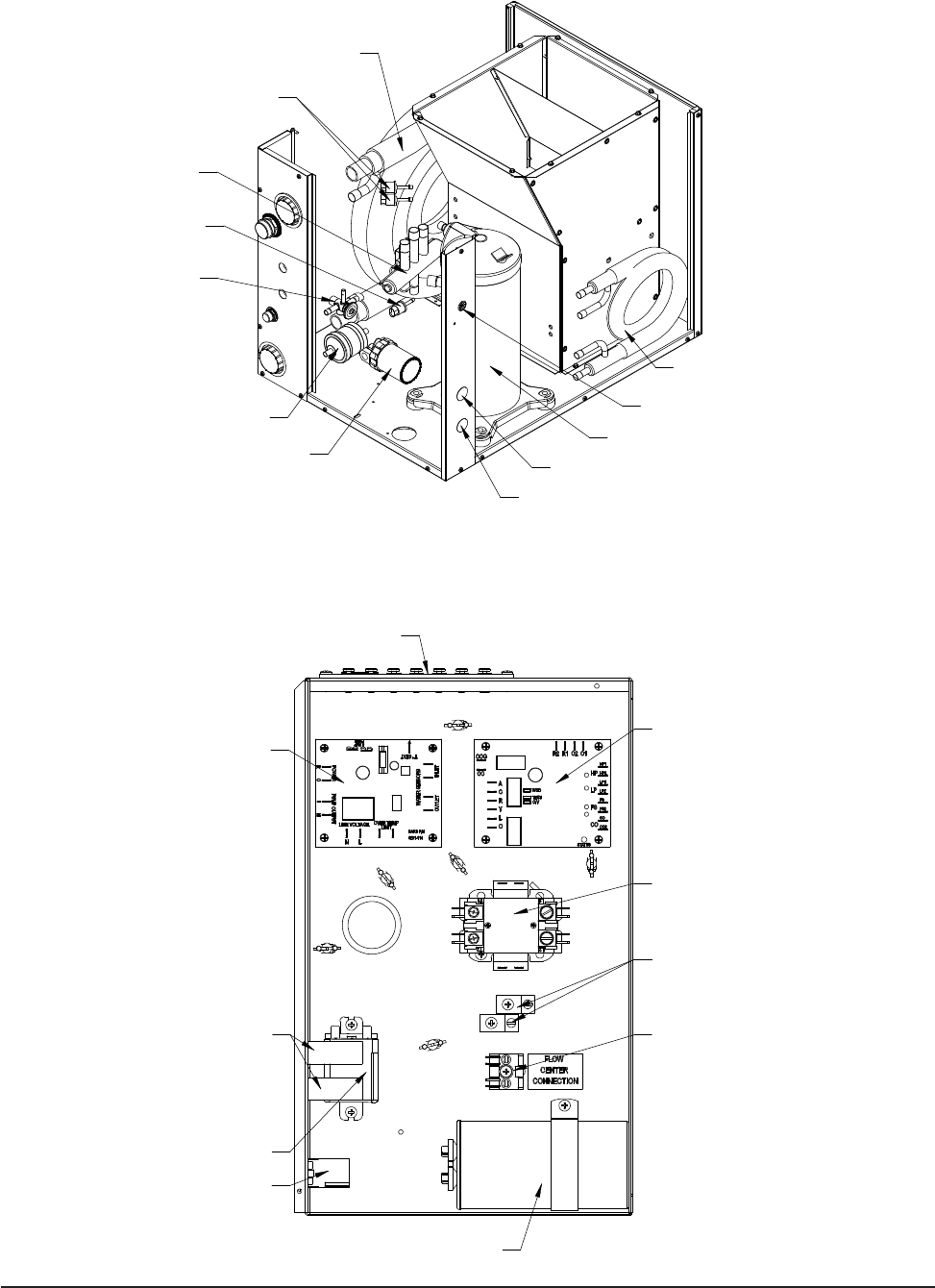
Manual 2100-537
I
Page 40 of 54
FIGURE 17 — COMPONENT LOCATION
FIGURE 18 — CONTROL PANEL
LOW VOLTAGE
REVERSING
VALVE
FILTER/DRIER
PUMP COMPRESSOR
DESUPERHEATER
COIL
EXPANSION
VALVE
LOW PRESSURE
SWITCHES
WATER COIL
HIGH PRESSURE
SWITCH
PUMP MODULE
HIGH VOLTAGE
UNIT HIGH VOLTAGE
MIS-2838
GEOTHERMAL
LOGIC CONTROL
CAPACITOR
COMPRESSOR
DESUPERHEATER
CONTROL BOARD
CIRCUIT BREAKERS
RELAY
PLUG
TERMINAL
STRIP
CONTACTOR
COMPRESSOR
GROUND TERMINALS
PUMP MODULE
POWER CONNECTION
MIS-2837
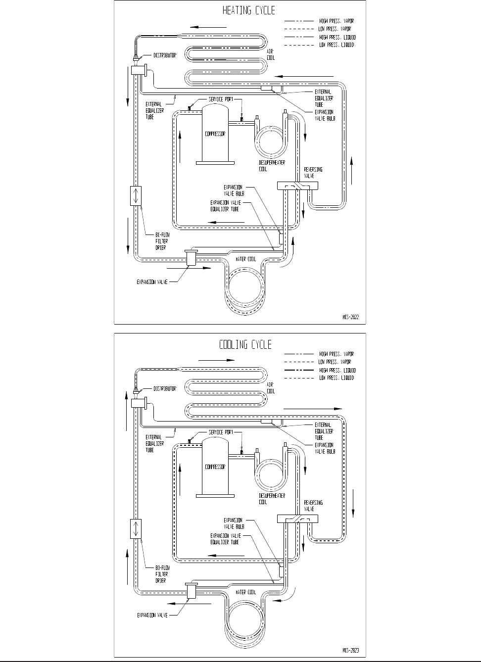
Manual 2100-537
I
Page 41 of 54
FIGURE 19

MODEL DESCRIPTION
R-410A CHARGE QUANTITY
(Ounces)
3/8" Line 7/8" Line Total
GTLS-03-1 3' Line Set 1.2 3 4.2
GTLS-15-1 15' Line Set 6 15 21
GTLS-25-1 25' Line Set 10 25 35
GTLS-35-1 35' Line Set 14 35 49
GTLS-50-1 50' Line Set 20 50 70
Manual 2100-537
I
Page 42 of 54
TABLE 9
PRE-CHARGED LINE SET REFRIGERANT QUANTITY
REFRIGERANT CHARGE
LINE SET INSTALLATION – GTA COIL
SECTIONS
CHARGE ADJUSTMENT
All supplied line sets with threaded refrigerant connections
are factory evacuated and charged with R-410A refrigerant
at the quantity required to optimize system performance.
Refer to Table 9 to see this charge quantity if you need to
reprocess the charge due to repairing damage or replacement
of a defective component.
For those using Stub Kits GTLS-SK2-1 or GTLS-SK4-1,
you will rst need to braze up both ends of your line set
(to the point that it is sealed). Ports are provided on the
GTLS-SK*-1 kits so that you can pull a vacuum on the
line set and pre-charge with refrigerant before screwing on
the refrigerant ttings onto the pre-charged condenser and
evaporator (if using one with threaded connectors).
For charge quantity, use Table 9 as a good general reference
to the required R-410A refrigerant required based upon your
line set length. Or, you can specically measure your line
set length, and add 1.4 ounces of R-410A refrigerant per 1'
of line set length.
REFRIGERANT FITTING ATTACHMENT
1. Coat all mating surface, including o-rings, with
R-410A refrigerant oil (Polyol Ester).
2. Attach female ttings to coil/condensing unit portion
by hand-threading initially. Be careful not to cross-
thread assembly. For the pre-manufactured 3' line
set used with a vertical (stacked) conguration, the
ttings should be threaded simultaneously. Again, be
careful not to cross-thread either assembly.
3. Final torque should be achieved. Use the appropriate
size wrench in conjunction with a second (backing)
wrench to ensure that ttings do not spin or twist on
the copper refrigerant lines. Use the following torque
rates:
3/8" Lineset – 22-25 ft. lbs. (30-35 Nm)
7/8" Lineset – 44-47 ft. lbs. (60-65 Nm)
CHECKING REFRIGERANT CHARGE
QUANTITY – GTA COIL SECTIONS
The correct R-410A charge is shown on the unit rating
plate (including adders for the various line set lengths).
Reference Figure 21 to validate proper system operation.
However, it is recommended that if incorrect charge is
suspected, the system refrigerant be reclaimed, evacuated,
and charged to nameplate charge quantity and type
(including necessary charge adjustment for the installed line
set length).
The nameplate charge quantity is optimized for thermal
performance and efciency throughout all modes of
operation.
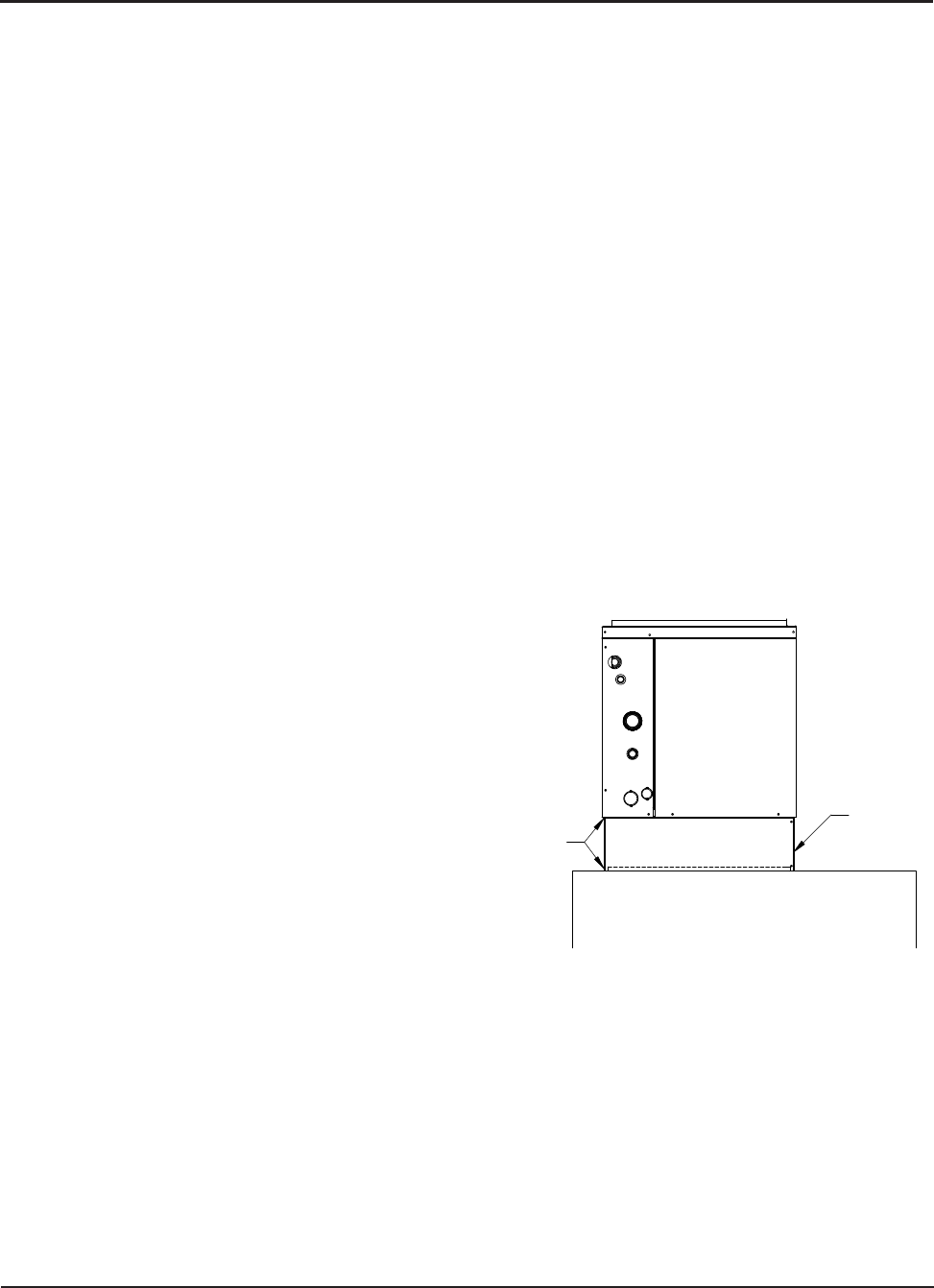
Manual 2100-537
I
Page 43 of 54
FIGURE 20
COIL SPACER
GENERAL – GTADP COIL SECTIONS
GENERAL (GTADP Add-On Coils)
These instructions are intended as a general guide and do not
supersede the coil manufacturer’s installation instructions
or local codes in any way. Read the manufacturer’s
installation manual and all “WARNING” statements
prior to installing the evaporator coil.
The following is needed, in addition to the evaporator coil.
1. Line Set Stub Kit with Single Pair Ends – Bard Part
No. GTLS-SK2-1
2. Line Set consisting of 7/8" and 3/8" soft rolled copper
with insulation.
3. Coil Spacer (Oil Furnaces Only)
Coils are shipped with a 10 PSIG dry air holding charge.
Puncture rubber plug on suction line to release charge
before removing plugs. The absence of pressure does not
verify a leak. Check the coil for leaks prior to installing if a
leak is suspected.
Position the coil/box directly on top of a gas furnace and
secure using sheet metal screws. The drain pans are made
of a polymer that can withstand temperatures up to 450˚F.
If installed on an oil or drum type heat exchanger (a coil
spacer is recommended to) maintain a 6 inch clearance
to protect the pan and to provide optimum air ow over
the coil. Coil should be level, or pitched slightly toward the
drain connections. See Figure 20.
LINE SET INSTALLATION (GTADP Add-On Coils)
Braze up one end of the line set to the GTLS-SK2-1 stub kit
and the other end to the evaporator coil. Ports are provided
in the GTLS-SK2-1 kit. Pull a vacuum (100 microns) on
the line set and coil. Pre-charge the line set and coil with
refrigerant before screwing the refrigerant ttings onto the
pre-charged condenser section.
REFRIGERANT CHARGE QUANTITY – Line Set
and Evaporator Coil (GTADP Add-On Coils)
The refrigerant charge shown on the GTC condenser section
is based on being matched with a GTA coil section and
not the ADP “A” coil. Charge adjustments are required
for proper system operation when using an ADP coil. Use
the following formulas to determine the amount of charge
required.
• GTC36 Line Set Charge = Line Set Length (FT) X 1.4
oz. R-410A/FT – 3.0 oz.
• GTC48 Line Set Charge = Line Set Length (FT) X 1.4
oz. R-410A/FT – 9.0 oz.
• GTC60 Line Set Charge = Line Set Length (FT) X 1.4
oz. R-410A/FT + 20.0 oz.
Example:
A GTC48 condenser section is being installed with a
GTADP-4860-C evaporator coil and a 25 foot line set.
GTC48 Line Set Charge = Line Set Length 25 (FT) X
1.4 oz. R-410A/FT – 9.0 oz.
GTC48 Line Set Charge = 26.0 oz.
DO NOT CONNECT THE LINE SET TO THE
CONDENSER SECTION
Pre-charge the line set and evaporator coil with the amount
of R-410A calculated earlier.
REFRIGERANT FITTING ATTACHMENT (After
pre-charging line set & coil) (GTADP Add-On Coils)
1. Coat all mating surfaces, including o-rings, with
R-410A refrigerant oil (Polyol Ester).
2. Attach female ttings to condensing unit portion by
hand-threading initially. Be careful not to cross-
thread assembly.
3. Final torque should be achieved. Use the appropriate
size wrench in conjunction with a second (backing)
wrench to ensure that the ttings do not spin or twist
on the copper refrigerant lines. Use the following
torque rates:
3/8" Line Set: 22-25 ft. lbs. (30-35 Nm)
7/8" Line Set: 44-47 ft. lbs. (60-65 Nm)
REFRIGERANT CHARGE
COIL SPACER
(IF REQUIRED)
ATTACH WITH
SCREWS TO
FLANGE
MIS-3127

Manual 2100-537
I
Page 44 of 54
REFRIGERANT CHARGE
These units require R-410A refrigerant and Polyol Ester.
GENERAL:
1. Use separate service equipment to avoid cross
contamination of oil and refrigerants.
2. Use recovery equipment rated for R-410A
refrigerant.
3. Use manifold gauges rated for R-410A (800 psi/250
psi low).
4. R-410A is a binary blend of HFC-32 and HFC-125.
5. R-410A is nearly azeotropic - similar to R-22 and
R-12. Although nearly azeotropic, charge with
liquid refrigerant.
6. R-410A operates at 40-70% higher pressure than
R-22, and systems designed for R-22 cannot
withstand this higher pressure.
7. R-410A has an ozone depletion potential of zero,
but must be reclaimed due to its global warming
potential.
8. R-410A compressors use Polyol Ester.
9. Polyol Ester oil is hygroscopic; it will rapidly absorb
moisture and strongly hold this moisture in the oil.
10. A liquid line dryer must be used - even a deep
vacuum will not separate moisture from the oil.
11. Limit atmospheric exposure to 15 minutes.
12. If compressor removal is necessary, always plug
compressor immediately after removal. Purge with
small amount of nitrogen when inserting plugs.
TOPPING OFF SYSTEM CHARGE
If a leak has occurred in the system, reclaiming,
evacuating (see criteria above), and charging to the
nameplate charge is recommended.
Topping off the system charge can be done without
problems. With R-410A, there are no signicant
changes in the refrigerant composition during multiple
leaks and recharges. R-410A refrigerant is close to being
an azeotropic blend (it behaves like a pure compound
or single component refrigerant). The remaining
refrigerant charge, in the system, may be used after leaks
have occurred and then “top-off” the charge by utilizing
the charging charts on the inner control panel cover as a
guideline.
REMEMBER: When adding R-410A refrigerant, it must
come out of the charging cylinder/tank as a liquid to
avoid any fractionation, and to insure optimal system
performance. Refer to instructions for the cylinder that
is being utilized for proper method of liquid extraction.
SAFETY PRACTICES:
1. Never mix R-410A with other refrigerants.
2. Use gloves and safety glasses, Polyol Ester oils can
be irritating to the skin, and liquid refrigerant will
freeze the skin.
3. Never use air and R-410A to leak check; the
mixture may become ammable.
4. Do not inhale R-410A – the vapor attacks the
nervous system, creating dizziness, loss of
coordination and slurred speech. Cardiac
irregularities, unconsciousness and ultimate death
can result from breathing this concentration.
5. Do not burn R-410A. This decomposition
produces hazardous vapors. Evacuate the area if
exposed.
6. Use only cylinders rated DOT4BA/4BW 400.
7. Never ll cylinders over 80% of total capacity.
8. Store cylinders in a cool area, out of direct
sunlight.
9. Never heat cylinders above 125°F.
10. Never trap liquid R-410A in manifold sets, gauge
lines or cylinders. R-410A expands signicantly
at warmer temperatures. Once a cylinder or line is
full of liquid, any further rise in temperature will
cause it to burst.

Model Return Air
Temperature Pressure FULL LOAD COOLING — Fluid Temperature Entering Water Coil °F
30°F 35°F 40°F 45°F 50°F 55°F 60°F 65°F 70°F 75°F 80°F 85°F 90°F 95°F 100°F 105°F 110°F
GTC36S2
75° DB
62° WB Low Side
High Side 108
148 111
163 113
177 116
192 118
206 121
221 123
235 126
250 128
264 129
286 129
309 130
331 131
353 131
376 132
398 132
420 133
442
80° DB
67° WB Low Side
High Side 116
152 118
167 121
182 124
196 126
211 129
226 132
241 134
256 137
271 138
294 138
317 139
340 140
362 140
385 141
408 142
431 142
454
85° DB
72° WB Low Side
High Side 124
157 127
173 130
188 133
203 136
219 139
234 142
250 144
265 147
280 148
304 149
328 149
351 150
375 151
399 152
422 152
446 153
470
GTC48S2
75° DB
62° WB Low Side
High Side 109
148 111
162 113
176 115
191 117
205 119
220 121
234 122
249 124
263 125
285 127
306 128
328 129
349 130
371 131
392 132
413 133
435
80° DB
67° WB Low Side
High Side 117
151 119
166 121
181 123
196 125
211 127
226 129
240 131
255 133
270 134
292 135
314 137
336 138
358 139
380 140
402 141
424 142
446
85° DB
72° WB Low Side
High Side 126
157 128
172 130
187 132
203 134
218 137
233 139
249 141
264 143
279 144
302 145
325 147
348 148
371 149
393 151
416 152
439 153
462
GTC60S2
75° DB
62° WB Low Side
High Side 116
139 117
154 117
169 117
183 117
198 118
213 118
228 118
243 119
257 120
278 122
298 123
318 125
338 127
358 128
378 130
398 131
419
80° DB
67° WB Low Side
High Side 124
143 125
158 125
173 125
188 126
203 126
219 126
234 127
249 127
264 129
285 130
305 132
326 134
347 135
367 137
388 139
409 140
429
85° DB
72° WB Low Side
High Side 134
148 134
163 134
179 135
195 135
210 135
226 135
242 136
258 137
273 138
295 140
316 142
337 144
359 145
380 147
402 149
423 151
444
Model Return Air
Temperature Pressure FULL LOAD HEATING — Fluid Temperature Entering Water Coil °F
5°F 10°F 15°F 20°F 25°F 30°F 35°F 40°F 45°F 50°F 55°F 60°F 65°F 70°F 75°F 80°F 85°F
GTC36S2 70° DB Low Side
High Side 45
242 52
252 59
262 66
272 72
282 79
292 86
302 93
312 99
322 106
332 117
342 129
353 140
363 151
373 162
383 174
394 185
404
GTC48S2 70° DB Low Side
High Side 36
247 44
258 52
270 60
281 68
293 76
304 84
316 92
327 100
339 108
350 119
361 129
372 140
383 150
394 161
405 171
416 182
427
GTC60S2 70° DB Low Side
High Side 38
264 46
273 54
282 62
292 70
301 78
310 86
319 94
329 102
338 110
347 118
357 126
366 134
376 142
385 150
395 158
404 166
414
Model Return Air
Temperature Pressure PART LOAD COOLING — Fluid Temperature Entering Water Coil °F
30°F 35°F 40°F 45°F 50°F 55°F 60°F 65°F 70°F 75°F 80°F 85°F 90°F 95°F 100°F 105°F 110°F
GTC36S2
75° DB
62° WB Low Side
High Side 116
130 119
144 121
159 123
173 126
188 128
202 130
216 133
231 135
245 135
265 135
284 135
303 135
322 135
341 136
360 136
379 136
398
80° DB
67° WB Low Side
High Side 124
133 127
148 129
163 132
177 134
192 137
207 139
222 142
237 144
252 144
271 145
291 145
310 145
330 145
349 145
369 145
389 145
408
85° DB
72° WB Low Side
High Side 134
138 136
153 139
168 142
184 144
199 147
214 150
230 153
245 155
261 155
281 155
301 156
321 156
341 156
362 156
382 156
402 156
422
GTC48S2
75° DB
62° WB Low Side
High Side 119
131 121
146 123
160 125
174 127
189 129
203 132
217 134
231 136
246 137
266 137
287 138
308 139
328 140
349 141
370 142
390 143
411
80° DB
67° WB Low Side
High Side 128
135 130
149 132
164 134
179 136
193 139
208 141
223 143
237 145
252 146
273 147
294 148
316 149
337 150
358 151
379 152
400 153
421
85° DB
72° WB Low Side
High Side 137
139 140
155 142
170 144
185 147
200 149
215 151
230 154
246 156
261 157
283 158
305 159
327 160
348 161
370 162
392 163
414 164
436
GTC60S2
75° DB
62° WB Low Side
High Side 127
122 127
137 127
152 127
167 128
182 128
197 128
212 129
227 129
242 130
262 131
282 131
302 132
322 133
342 134
362 134
382 135
402
80° DB
67° WB Low Side
High Side 135
125 136
141 136
156 136
171 137
187 137
202 137
217 138
233 138
248 139
269 140
289 141
310 141
330 142
351 143
371 144
392 145
412
85° DB
72° WB Low Side
High Side 145
130 146
146 146
161 147
177 147
193 147
209 148
225 148
241 148
257 149
278 150
299 151
320 152
342 153
363 154
384 155
405 156
426
Model Return Air
Temperature Pressure PART LOAD HEATING — Fluid Temperature Entering Water Coil °F
5°F 10°F 15°F 20°F 25°F 30°F 35°F 40°F 45°F 50°F 55°F 60°F 65°F 70°F 75°F 80°F 85°F
GTC36S2 70° DB Low Side
High Side 23
238 35
247 46
256 57
264 68
273 80
288 91
296 102
305 111
317 120
328 131
337 143
346 154
354 165
363 176
372 188
381 199
389
GTC48S2 70° DB Low Side
High Side 20
228 31
238 43
247 54
257 66
266 77
281 89
291 100
300 109
311 117
322 129
332 140
341 152
351 163
360 175
370 186
379 198
389
GTC60S2 70° DB Low Side
High Side 27
236 38
247 48
257 58
268 68
278 79
294 89
305 99
315 109
326 119
336 129
347 140
357 150
368 160
378 170
389 181
399 191
410
Manual 2100-537
I
Page 45 of 54
FIGURE 21
PRESSURE TABLES
LOW SIDE PRESSURE +/- 2 PSIG
HIGH SIDE PRESSURE +/- 5 PSIG
TablesbaseduponratedCFM(airow)acrosstheevaporatorcoil.
If incorrect charge suspected (more than +2 psig suction, +5psigliquid),itisrecommendedrefrigerantchargebereclaimed,systemevacuatedandcharged
toserialplatequantity.
Manual 2100-537
I
Page 46 of 54
Manual 2100-537G
Page 44 of 52
Heat Gen.
Power Failure
Blown Fuse or Tripped Breaker
Faulty Wiring
Loose Terminals
Low Voltage
Defective Contacts in Contactor
Compressor Overload
Potential Relay
Run Capacitor
Start Capacitor
Faulty Wiring
Loose Terminals
Control Transformer
Low Voltage
Thermostat
Contactor Coil
Pressure Controls (High or Low)
Indoor Blower Relay
Discharge Line Hitting Inside of Shell
Bearings Defective
Seized
Valve Defective
Motor Wingings Defective
Refrigerant Charge Low
Refrigerant Overcharge
High Head Pressure
Low Head Pressure
High Suction Pressure
Low Suction Pressure
Non-Condensables
Unequalized Pressures
Solenoid Valve Stuck Closed (Htg)
Solenoid Valve Stuck Closed (Clg)
Solenoid Valve Stuck Open (Htg or Clg)
Leaking
Defective Valve or Coil
Plugged or Restricted Metering Device (Htg)
Scaled or Plugged Coil (Htg)
Scaled or Plugged Coil (CLg)
Water Volume Low (Htg)
Water Volume Low (Clg)
Low Water Temperature (Htg)
Plugged or Restricted Metering Device (Clg)
Fins Dirty or Plugged
Motor Winding Defective
Air Volume Low
Air Filters Dirty
Undersized or Restricted Ductwork
Auxillary Heat Upstream of Coil
Compressor Will Not Run
No Power at Contactor
Compressor Will Not Run
Power at Contactor
Compressor "Hums"
But Will Not Start
Compressor Cycles on Overload
Thermostat Check Light
Lite-Lockout Relay
Compressor Off on High
Pressure Control
Compressor Off on Low
Pressure Control
Compressor Noisy
Head Pressure Too High
Head Pressure Too Low
Suction Pressure Too High
Suction Pressure Too Low
I.D. Blower Will Not Start
I.D. Coil Frosting or Icing
High Compressor Amps
Excessive Water Usage
Compressor Runs Continuously
– No Cooling
Liquid Refrigerant Flooding Back
To Compressor
Compressor Runs Continuously
– No Heating
Reversing Valve Does Not Shift
Liquid Refrigerant Flooding Back
To Compressor
Aux. Heat on I.D. Blower Off
Excessive Operation Costs
Ice in Water Coil
Heating Cycle
AUX.
Cooling
Cycle Heating or Cooling Cycles
I
ndoor Blower Motor
and Coil
INDOOR SECTIONPOWER SUPPLY
W
ater
Solenoid
R
ev.
Valve Water Coil
WATER COIL SECTION
Line Voltage Control Circuit Compressor Refrigerant System
QUICK REFERENCE TROUBLESHOOTING CHART FOR WATER TO AIR HEAT PUMP
Denotes common cause
Denotes occasional cause
QUICK REFERENCE TROUBLESHOOTING CHART FOR WATER TO AIR HEAT PUMP
Manual 2100-537
I
Page 47 of 54
SERVICE
SERVICE HINTS
1. Caution owner to maintain clean air lters at all times.
Also, not to needlessly close off supply and return air
registers. This reduces airow through the system,
which shortens equipment service life as well as
increasing operating costs.
2. Check all power fuses or circuit breakers to be sure that
they are the correct rating.
UNBRAZING SYSTEM COMPONENTS
If the refrigerant charge is removed from a scroll equipped
unit by bleeding the high side only, it is sometimes possible
for the scrolls to seal, preventing pressure equalization
through the compressor. This may leave low side shell and
suction line tubing pressurized. If the brazing torch is then
applied to the low side while the low side shell and suction
line contains pressure, the pressurized refrigerant and
oil mixture could ignite when it escapes and contacts the
brazing ame. To prevent this occurrence, it is important
to check both the high and low side with manifold gauges
before unbrazing.
ECM MOTOR
This unit is equipped with an ECM motor. It is important
that the blower motor plugs are not plugged in or unplugged
while the power is on. Failure to remove power prior to
unplugging or plugging in the motor could result in motor
failure.
WARNING
Both the high and low side of the scroll compressor
must be checked with manifold gauges before
unbrazing system components. Failure to do so
could cause pressurized refrigerant and oil mixture
toigniteifitescapesandcontactsthebrazingame
causing property damage, bodily harm or death.
COMPRESSOR SOLENOID
(See Sequence of Operation on Pages 37 & 38 for function.)
A nominal 24-volt direct current coil activates the internal
compressor solenoid. The input control circuit voltage must
be 18 to 28 volts ac. The coil power requirement is 20 VA.
The external electrical connection is made with a molded
plug assembly. This plug contains a full wave rectier to
supply direct current to the unloader coil.
Compressor Solenoid Test Procedure – If it is suspected
that the unloader is not working, the following methods may
be used to verify operation.
1. Operate the system and measure compressor amperage.
Cycle the compressor solenoid on and off at 10-second
intervals. The compressor amperage should go up or
down at least 25 percent.
2. If step one does not give the expected results, shut unit
off. Apply 18 to 28 volts ac to the solenoid molded
plug leads and listen for a click as the solenoid pulls
in. Remove power and listen for another click as the
solenoid returns to its original position.
3. If clicks can’t be heard, shut off power and remove the
control circuit molded plug from the compressor and
measure the solenoid coil resistance. The resistance
should be 32 to 60 ohms depending on compressor
temperature.
4. Next, check the molded plug.
Voltage check: Apply control voltage to the plug wires
(18 to 28 volts ac). The measured dc voltage at the female
connectors in the plug should be around 15 to 27 vdc.
Resistance check: Measure the resistance from the end of
one molded plug lead to either of the two female connectors
in the plug. One of the connectors should read close to zero
ohms, while the other should read innity. Repeat with
other wire. The same female connector as before should
read zero, while the other connector again reads innity.
Reverse polarity on the ohmmeter leads and repeat. The
female connector that read innity previously should now
read close to zero ohms.
Replace plug if either of these test methods does not show
the desired results.
CAUTION
Do not plug in or unplug blower motor
connectors while the power is on. Failure
to do so may result in motor failure.

Manual 2100-537
I
Page 48 of 54
TROUBLESHOOTING GE ECM 2.3™ MOTORS
CAUTION:
Disconnect power from unit before removing or replacing
connectors, or servicing motor. To avoid electric shock from
the motor’s capacitors, disconnect power and wait at least 5
minutes before opening motor.
Symptom Cause/Procedure
Motor rocks slightly • This is normal start-up for ECM
when starting
Motor won’t start • Check blower turns by hand
• No movement • Check power at motor
• Check low voltage (24 Vac R to C) at motor
• Check low voltage connections
(G, Y, W, R, C) at motor
• Check for unseated pins in connectors on
motor harness
• Test with a temporary jumper between R - G
• Check motor for tight shaft
• Perform motor/control replacement check
• Perform Moisture Check
• Motor rocks, • Check for loose or compliant motor mount
but won’t start • Make sure blower wheel is tight on shaft
• Perform motor/control replacement check
Motor oscillates up • It is normal for motor to oscillate with no
load & down while being on shaft
tested off of blower
Motor starts, but
runs erratically
• Varies up and down • Check line voltage for variation or “sag”
or intermittent • Check low voltage connections
(G, Y, W, R, C) at motor, unseated pins in
motor harness connectors
• Check “Bk” for erratic CFM command (in
variable-speed applications)
• Check out system controls, Thermostat
• Perform Moisture Check
• “Hunts” or “puffs” at • Does removing panel or lter reduce
high CFM (speed) “pufng”?
- Reduce restriction
- Reduce max airow
• Stays at low CFM • Check low voltage (Thermostat) wires and
despite system call connections
for cool or heat CFM • Verify fan is not in delay mode; wait until
delay complete
• “R” missing/not connected at motor
• Perform motor/control replacement check
• Stays at high CFM • “R” missing/not connected at motor
• Is fan in delay mode? - wait until delay time
complete
• Perform motor/control replacement check
• Blower won’t shut off •
Current leakage from controls into G, Y or W?
Check for Triac switched thermostat or solid-
state relay
Excessive noise • Determine if it’s air noise, cabinet, duct or
motor noise; interview customer, if necessary
• Air noise • High static creating high blower speed?
- Is airow set properly?
- Does removing lter cause blower to slow
down? Check lter
- Use low-pressure drop lter
- Check/correct duct restrictions
Symptom Cause/Procedure
• Noisy blower or cabinet • Check for loose blower housing, panels, etc.
• High static creating high blower speed?
- Check for air whistling through seams in
ducts, cabinets or panels
- Check for cabinet/duct deformation
• “Hunts” or “puffs” at • Does removing panel or lter reduce
high CFM (speed) “pufng”?
- Reduce restriction
- Reduce max. airow
Evidence of Moisture
• Motor failure or • Replace motor and
Perform Moisture Check
malfunction has occurred
and moisture is present
• Evidence of moisture • Perform Moisture Check
present inside air mover
Do Don’t
• Check out motor, controls, • Automatically assume the motor is bad.
wiring and connections
thoroughly before replacing
motor
• Orient connectors down so • Locate connectors above 7 and 4 o’clock
water can’t get in positions
- Install “drip loops”
• Use authorized motor and • Replace one motor or control model # with
model #’s for replacement another (unless an authorized replacement)
• Keep static pressure to a • Use high pressure drop lters some have
½”
minimum: H20 drop!
- Recommend high • Use restricted returns
efciency, low static lters
- Recommend keeping lters
clean.
- Design ductwork for min.
static, max. comfort
- Look for and recommend
ductwork improvement,
where necessary
• Size the equipment wisely • Oversize system, then compensate with low
airow
• Check orientation before • Plug in power connector backwards
inserting motor connectors • Force plugs
Moisture Check
• Connectors are oriented “down” (or as recommended by equipment
manufacturer)
• Arrange harness with “drip loop” under motor
• Is condensate drain plugged?
• Check for low airow (too much latent capacity)
• Check for undercharged condition
• Check and plug leaks in return ducts, cabinet
Comfort Check
• Check proper airow settings
• Low static pressure for lowest noise
• Set low continuous-fan CFM
• Use humidistat and 2-speed cooling units
• Use zoning controls designed for ECM that regulate CFM
• Thermostat in bad location?
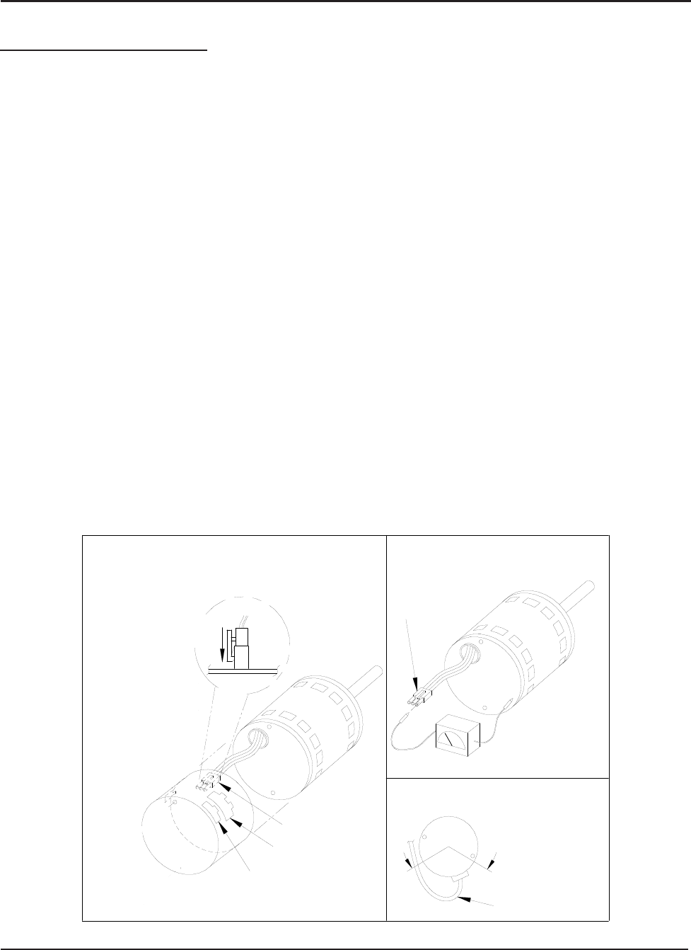
Motor
Motor OK when
R > 100k ohm
ECM 2.0
Only remove
Hex Head Bolts
Connector Orientation
Between 4 and 8 o'clock
Drip Loop
Back of
Control
Figure 5
Winding Test
Figure 4
Note:
Use the shorter
bolts and
alignment pin
supplied when
replacing an
ECM 2.0
control.
Figure 3
ECM
2.3/2.5
Power Connector
(5-pin)
Control Connector
(16-pin)
Hex-head Screws
Motor Connector
(3-pin)
Motor Connector
(3-pin)
Control Disassembly
Drip Loop
Push until
Latch Seats
Over Ramp
From Motor
Circuit
Board
Manual 2100-537
I
Page 49 of 54
Figure 22 Figure 23
Figure 24
TROUBLESHOOTING GE ECM™ MOTORS CONT’D.
Replacing ECM Control Module
To replace the control module for the GE variable-speed indoor blower
motor you need to take the following steps:
1. You MUST have the correct replacement module. The controls are
factory programmed for specic operating modes. Even though they look
alike, different modules may have completely different functionality.
USING THE WRONG CONTROL MODULE VOIDS ALL PRODUCT
WARRANTIES AND MAY PRODUCE UNEXPECTED RESULTS.
2. Begin by removing AC power from the unit being serviced. DO NOT
WORK ON THE MOTOR WITH AC POWER APPLIED. To avoid
electric shock from the motor’s capacitors, disconnect power and wait at
least 5 minutes before opening motor.
3. It is not necessary to remove the motor from the blower assembly, nor
the blower assembly from the unit. Unplug the two cable connectors to the
motor control assembly. There are latches on each connector. DO NOT
PULL ON THE WIRES. The plugs remove easily when properly released.
4. Locate the screws that retain to t
he motor control bracket to the sheet
metal of the unit and remove them. Remove two (2) nuts that retain
the control to the bracket and then remove two (2) nuts that retain sheet
metal motor control end plate. Refer to Figure 22.
5. Disconnect the three (3) wires interior of the motor control by using
your thumb and forenger squeezing the latch tab and the opposite side
of the connector plug, gently pulling the connector. DO NOT PULL ON
THE WIRES, GRIP THE PLUG ONLY. Refer to Figure 22.
6. The control module is now completely detached from the motor.
Verify with a standard ohmmeter that the resistance from each motor
lead (in the motor plug just removed) to the motor shell is >100K ohms.
Refer to Figure 23. (Measure to unpainted motor end plate.) If any
motor lead fails this test, do not proceed to install the control module.
THE MOTOR IS DEFECTIVE AND MUST BE REPLACED.
Installing the new control module will cause it to fail also.
7. Verify that the replacement control is correct for your application.
Refer to the manufacturer’s authorized replacement list. USING THE
WRONG CONTROL WILL RESULT IN IMPROPER OR NO
BLOWER OPERATION. Orient the control module so that the 3-wire
motor plug can be inserted into the socket in the control. Carefully insert
the plug and press it into the socket until it latches. A SLIGHT CLICK
WILL BE HEARD WHEN PROPERLY INSERTED.
8. Reverse the steps #5, 4, 3 to reconnect the motor control to the
motor wires, securing the motor control cover plate, mounting the
control to the bracket, and mounting the motor control bracket back
into the unit. MAKE SURE THE ORIENTATION YOU SELECT
FOR REPLACING THE CONTROL ASSURES THE CONTROL’S
CABLE CONNECTORS WILL BE LOCATED DOWNWARD
IN THE APPLICATION SO THAT WATER CANNOT RUN
DOWN THE CABLES AND INTO THE CONTROL. DO NOT
OVERTIGHTEN THE BOLTS.
9. Plug the 16-pin control plug into the motor. The plug is keyed.
Make sure the connector is properly seated and latched.
10. Plug the 5-pin power connector into the motor. Even though the
plug is keyed, OBSERVE THE PROPER ORIENTATION. DO NOT
FORCE THE CONNECTOR. It plugs in very easily when properly
oriented. REVERSING THIS PLUG WILL CAUSE IMMEDIATE
FAILURE OF THE CONTROL MODULE.
11.
Final installation check. Make sure the motor is installed as follows:
a. Motor connectors should be oriented between the 4 o’clock
and 8 o’clock positions when the control is positioned in its
nal location and orientation.
b. Add a drip loop to the cables so that water cannot enter the
motor by draining down the cables. Refer to Figure 24.
The installation is now complete. Reapply the AC power to the HVAC
equipment and verify that the new motor control module is working
properly. Follow the manufacturer’s procedures for disposition of the
old control module.
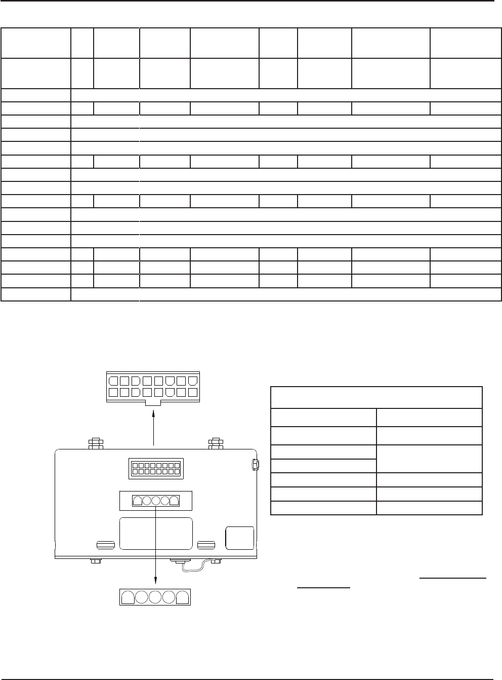
Manual 2100-537
I
Page 50 of 54
TROUBLESHOOTING GE ECM™ MOTORS CONT’D.
10
1 2 3 4 5 6 7 8
1615141312119
3 51 2 4
MIS-2839
FIGURE 25
CONTROL CONNECTOR MOTOR HALF
*
Suggested mating connector
Housing — AMP 350809-1
Contact — AMP 350537-1
** WARNING — Applying 240VAC line input with
PIN 1 to PIN 2 jumper in place will permanently
damage unit!
POWER CONNECTOR
MOTOR HALF
MODE of
OPERATION OFF
Continuous
Blower
Part Load
Cooling Full Load Cooling Part
Load
Heating
Full Load
Heating
Full Load Heating +
Electric Heat
Stage #1
Emergency Heat
Mode
Thermostat
24 VAC Inuput
Signals — "G" "G", "Y1", "O" "G", "Y1", "Y2", "O" "G", "Y1" "G", "Y1", "Y2" "G", "Y1", "Y2", "W1" "G", "E", "W1", "W2"
Pin #1 24 VAC "C" (Common) Signal, Always Energized
Pin #2 X X
Pin #3 24 VAC "C" (Common) Signal, Always Energized
Pin #4 DelayTapProles,VariedHalf-WaveSignalsBasedUponSettings
Pin #5 Cool Tap Select Tables, Varied Half-Wave Signals Based Upon Settings (Tonnage)
Pin #6 X X X X X
Pin #7 AdjustmentTapProles,VariedHalf-WaveSignalsBasedUponSettings
Pin #8 DC Volts "-" Output in Direct Correlation to CFM
Pin #9 X X
Pin #10 Future Use; Not Currently Programmed for Function
Pin #11 Heat Tap Select Tables, Varied Half-Wave Signals Based Upon Tonnage
Pin #12 24 VAC Hot "R" Signal, Always Energized
Pin #13 X
Pin #14 X X
Pin #15 X X X X X X X
Pin #16 DC Volts "+" Output in Direct Correlation to CFM
POWER CONNECTOR *
PWB HEADER AMP 1-350945-0
PIN Description
1Jumper Pin 1 to Pin 2 for
120VAC Line Input Only **
2
3 Chassis Ground
4 AC Line
5 AC Line

Manual 2100-537G
Page 49 of 52
GROUND SOURCE HEAT PUMP
PERFORMANCE REPORT
This performance check report should be filled out by installer and retained with unit.
DATE TAKEN BY:
1. UNIT:
Mfgr Model No. S/N
THERMOSTAT:
Mfgr Model No. P/N
2. Person Reporting
3. Company Reporting
4. Installed By Date Installed
5. User’s (Owner’s) Name
Address
6. Unit Location
WATER SYSTEM INFORMATION
7. Open Loop System (Water Well) Closed Loop System
A. If Open Loop where is water discharged?
8. The following questions are for Closed Loop systems only
A. Closed loop system designed by
B. Type of antifreeze used % Solution
C. System type: Series Parallel
D. Pipe material Nominal Size
E. Pipe Installed:
1. Horizontal Total length of pipe ft
No. pipes in trench Depth bottom pipe ft
2. Vertical Total length of bore hole ft
Manual 2100-537
I
Page 51 of 54
GROUND SOURCE HEAT PUMP
PERFORMANCE REPORT
Thisperformancecheckreportshouldbelledoutbyinstallerandretainedwithunit.
Manual 2100-537G
Page 50 of 52
THE FOLLOWING INFORMATION IS NEEDED
TO CHECK PERFORMANCE OF UNIT.
FLUID SIDE DATA Cooling ** Heating
9. Entering fluid temperature F
10. Leaving fluid temperature F
11. Entering fluid pressure PSIG
12. Leaving fluid pressure PSIG
13. Pressure drop through coil PSIG
14. Gallons per minute through the water coil GPM
15. Liquid or discharge line pressure PSIG
16. Suction line pressure PSIG
17. Voltage at compressor (unit running) V
18. Amperage draw at line side of contactor A
19. Amperage at compressor common terminal A
20. * Suction line temperature 6” from compressor F
21. * Superheat at compressor F
22. * Liquid line temperature at metering device F
23. * Coil subcooling F
INDOOR SIDE DATA Cooling ** Heating
24. Dry bulb temperature at air entering indoor coil F
25. Wet bulb temperature of air entering indoor coil F
26. Dry bulb temperature of air leaving indoor coil F
27. Wet bulb temperature of air leaving indoor coil F
28. * Supply air static pressure (packaged unit) WC
29. * Return air static pressure (packaged unit) WC
30. Other information about installation
** When performing a heating test insure that 2nd stage heat is not activated
* Items that are optional
Manual 2100-537
I
Page 52 of 54
THE FOLLOWING INFORMATION IS NEEDED
TO CHECK PERFORMANCE OF UNIT.
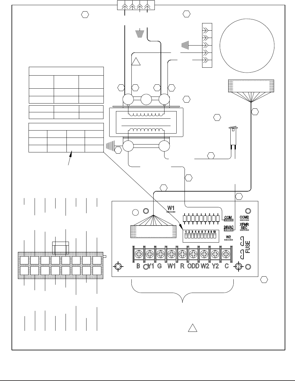
Manual 2100-537
I
Page 53 of 54
TO 208V TRANSFORMER
1FOR 208V OPERATION,
MOVE THIS RED WIRE
TAP
Blower
Indoor
Motor
3A
GREEN
1
OFF
OFF
2ON
OFF
POWER PLUG
RED
RED
431 2
5
4
3
1
2
RED/WHITE
16-PIN BLOWER
POWER PLUG
240V
OFF
ON
4-PIN UNIT
CONTROL PLUG
5-PIN MOTOR
BREAKER
RED/WHITE
YELLOW/RED
ORANGE
PURPLE
RED/YELLOW
RED/WHITE
RED
PURPLE/WHITE
BLUE
16 15 1314 12 1011 9
28 37
208/230-60-1
456
YELLOW/BLACK
BLACK/WHITE
BROWN
BLACK/WHITE
GRAY
2
8
BLUE/BLACK
YELLOW
OFF
OFF CIRCUIT
CONTROL PLUG
FIELD CONNECTIONS TO THERMOSTAT
SWITCH #
1
BLACK
COM
OFF
TRANSFORMER
5
ON
16-PIN BLOWER
6
CR
3
AND CONDENSING SECTION
DIP
4
208V
MODEL
GTC36S1GTC48S1GTC60S1
1
ECM
CONTROL
77
7
9
77
3
8
12
10
OFF
7
ON
9
OFFON
11
ADJUSTMENT TAPS
NONE "+10%" "-10%" NONE
OFF ON OFF ON
OFF OFF ON ON
BLACK
BLACK
BLACK/WHITE
4117-100 B
NOTE: SWITCH #4 MUST BE TURNED
ON WHEN BLOWER IS CONVERTED TO
COUNTERFLOW OR HORIZONTAL
RIGHT DISCHARGE
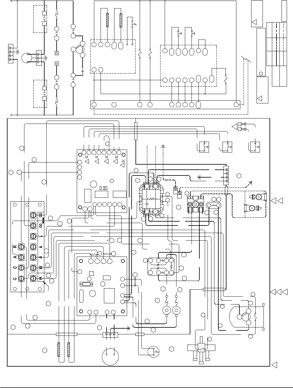
Manual 2100-537
I
Page 54 of 54
USE COPPER CONDUCTORS
ONLY SUITABLE FOR AT LEAST
75° C.
WARNING
!
*DISCONNECT POWER BEFORE
!
DANGER
*ELECTRICAL SHOCK HAZARD
SERVICING.
Wire Identification numbers
99
for Bard use only.
2L.P.S = Orange fault light illuminated when fault indicated.
H.P.S = Green fault light illuminated when fault indicated.
4
3F.S. = Red fault light illumninated when fault indicated.
1 3
4 6
7 9
A B
21 3
3
PUSH
High Speed
Compressor
C
S
R
Solenoid
THERMISTOR
THERMISTOR
Y
OUT
OUT
IN
IN
LN
I
N
C
R
3
POWER PUMP OUTPUT
LINE VOLTAGE OVERTEMP
LIMIT
WATER SENSORS
T ' STAT
3
PUSH
T1
L2
T2
L1
34 2 1
1FOR ANTIFREEZE LOOP APPLICATIONS, CHANGE
LOW PRESSURE SWITCH TO YELLOW LEADS
ON LPC TERMINALS OF GEOTHERMAL LOGIC
CONTROL BOARD
C1
2
HP1
C2R1R2
FS
HP2
LP1
LP2
O
FS2
CO
CO2
C
L
Y
R
A
CCG
CC
STATUS
O/V
TEST
6
5
4
3
WSD
8
GEOTHERMAL
LOGIC CONTROL
41 2 3
L I
PUMP
LINE
VOLTAGE OUTPUT PUMP
OUTPUT
LINE
NN
VOLTAGE
T1L1
S
Compressor
C
R
L2T2
Compressor
Contactor
Compressor
Contactor
Capacitor
9 6 4 7
1 32
LP1
LP2
FS
FS2
C1
CCG
CC
COG
CO
L
Y
A
GEOTHERMAL
LOGIC
CONTROL
HP1
HP2
R1
A
Y2
O
E
C
COG
CO
L
Y1
R
IN
DESUPERHEATER
LOGIC
CONTROL
OVER-TEMP
Y
R
OUT
OUT
IN
C
LIMIT
Factory Optional
5
Low Voltage
High Voltage
6
Field
1
4117-101 C
PINK
BLUE/WHITE
BLUE
BLUE
BLUE
BLUE
BLUE
BLUE
BLUE
BLUE
BLUE/WHITE
GRAY
GRAY
GRAY
GRAY
GREEN
YELLOW
YELLOW
YELLOW
YELLOW
YELLOW/RED
YELLOW
YELLOW/RED
GREEN
BROWN/WHITE
BROWN/WHITE
COMPRESSOR
STAGING SOLENOID
REVERSING VALVE SOLENOID
24 VAC FROM AIR HANDLING UNIT
COND. = Yellow fault light illuminated when fault indicated.
RED/WHITE
RED
RED
RED
RED
RED
RED
RED
RED
RED/WHITE
RED
SWITCH
LOW
SWITCH
CONTACTOR
RED
RED
PRESSURE
PRESSURE
RED
RED
HIGH
COMPRESSOR
RED
10
PUMP MOTOR
22
WATER
CONNECTED
FIELD
20
VALVE
REVERSING
DESUPERHEATER
LIMIT
LUG
GROUND
20
BLACK
208/230-60-1
TEMPERATURE
TERMINAL STRIP
LOW VOLTAGE
19
LINE POWER
3
LABEL
CONTROL
DESUPERHEATER
4
CAPACITOR
SCREW TO TAB
6
FLOW CENTER
BREAKER
BLACK/WHITE
BLACK/WHITE
BLACK
12
BLACK
SWITCH (WATER)
LOW PRESSURE
SWITCH (ANTI-FREEZE)
LOW PRESSURE
13
SWITCH
HIGH PRESSURE
RELAY
WHITE
14
BLACK
CIRCUIT
CONTACTOR
COMPRESSOR
THRU GEOTHERMAL LOGIC CONTROL
BLACK/WHITE
9
BLACK/
BLACK
11
BLACK
TEMP. SENSORS
DESUPERHEATER
WHITE
CONNECTED FOR DIRECT CONTROL
18 WHITE
BLACK
17
BLACK
BLACK/
1
POWER PLUG
4-PIN BLOWER
230V WATER CIRCULATING PUMP(S)
OPTIONAL
38
39
BLACK
40
BLACK/WHITE 25
35
24 24
40
40 40
31
32
29
30
37
27
27
22
21
23 24 24 25
26
BLACK
36
RED
35
RED
35
BLACK
38
BLACK
38
BLACK/WHITE
21
35
33
39
40
40
17 23
29
30
3-PIN PLUG
28
34
21
18
43
Status = Green Status LED will blink in normal operation.
LOGIC CONTROL
3-AMP
DESUPERHEATER
LOGIC CONTROL DESUPERHEATER
CIRCUIT BREAKER
TERMINAL BLOCK
THERMISTOR
FLOW CENTER RELAY
POWER PLUG
L2
L1
LIMIT
208/230-60-1 POWER SOURCE
3-AMP
PUMP MOTOR
4-PIN BLOWER
CIRCUIT BREAKER
DESUPERHEATER
3-PIN PLUG
FLOW CENTER RELAY
FLOW CENTER
THERMISTOR
