Bosch Automotive Diagnostics Equipment KT700VCI WIFI device with USB, RJ45 power for data transfer User Manual
Bosch Automotive Diagnostics Equipment (Shenzhen) Limited WIFI device with USB, RJ45 power for data transfer
User Manual
VCI User Manual

Bosch Automotive Diagnostics Equipment (Shenzhen) Limited
| VCI | 3VCI | 3 | 3 en
1. Symbols used 4
1.1 In the documentation 4
1.1.1 Warning notices - Structure and meaning
4
1.1.2 Symbols in this documentation 4
1.2 On the product 4
2. Important notes 4
2.1 User group 4
2.2 Agreement 5
2.3 Obligation of contractor 6
3. Safety instructions 6
3.1 Risk of electric shocks 6
3.1.1 Low voltages, high voltages 6
3.1.2 High voltages in hybrid vehicles and elec-
tric vehicles as well as their high-voltage
components 7
3.2 Danger of acid burning 7
3.3 Danger of injury, Danger of crushing 8
3.4 Danger of burning 8
3.5 Danger of fire, Danger of explosion 9
3.6 Danger of asphyxiation 9
3.7 Noise 9
3.8 Danger of tripping 9
3.9 FCC Warning 10
3.10 WLAN (Wireless Local Area Network) 10
3.10.1 Important information on WLAN 10
3.10.2 Information on access points 11
3.11 Satety Warning 11
3.12 Using notes 12
3.13 Notes for operation of automobile ECU 12
4. PC Software environment 13
4.1 Computer parameters 13
4.2 Installation guidance 13
4.2.1 VCI Software installation 13
4.3 Software uninstall 13
5. Introduction to VCI host 14
5.1 Host identifications 14
5.2 Diagnosis port 14
5.3 Connection Port 14
6. Equipment connection 14
6.1 Diagnostic connection 14
6.2 Selfcheck connection 15
6.3 Firmware upgrade connection 15
7. Initial Start-up 16
8. VCI system settings 16
8.1 System Settings 16
8.1.1 Language Settings 16
8.1.2 System information 16
8.1.3 User information 16
8.1.4 Proxy Settings 16
8.1.5 Product Activation 17
8.2 Software upgrade 17
8.2.1 Software Upgrade 17
8.2.2 VCI Firmware Upgrade 17
8.3 VCI 18
8.3.1 VCI Communication Settings 18
8.3.2 VCI Information 18
8.3.3 VCI Selfcheck 18
8.4 Vehicle Logo Replacement 19
8.4.1 Single Replacement 19
8.4.2 Integral Replacement 19
9. Vehicle Diagnostic 19
9.1 Test Conditions 19
9.2 Power supply of host 19
9.3 Selecting a Method to Access the Diagnosis
System 20
9.3.1 Manual Selection 20
9.3.2 Brand Search 20
9.3.3 History Record 20
9.4 Diagnostic 20
9.4.1 Introduction to Main Interface of Diagno-
sis System 20
9.4.2 Reading Version Information 20
9.4.3 Reading DTC 21
9.4.4 Clearing DTC 21
9.4.5 Reading Data Stream 22
9.4.6 Travel Recorder 23
9.4.7 Playing Back Data Stream 24
9.4.8 Action Test 24
9.4.9 Advanced Functions 24
9.5 Other Functions Related to Diagnostic 25
9.5.1 Print 25
9.5.2 Image Browse 26
9.5.3 Screenshot 26
9.5.4 Help 26
9.5.5 Feedback 26
9.6 Service Help 26
10. Service and Maintenance 27
10.1 Cleaning 27
10.2 Maintenance 27
11. Technical Parameters 27
11.1 Host Parameters 27
12. Warranty 27
Contents
Bosch Automotive Diagnostics Equipment (Shenzhen) Limited
4 | VCI | Symbols useden
1. Symbols used
1.1 In the documentation
1.1.1 Warning notices - Structure and meaning
Warning notices indicate hazards and their consequen-
ces for the user or surrounding persons. Warning noti-
ces also describe the measures for preventing these
hazards. The signal word has a crucial importance. It
indicates the probability of occurrence and the severity
of the hazard in case of non-compliance:
Signal
word
Probability of
occurrence
Severity of danger if in-
structions not observed
DANGER Immediate impend-
ing danger
Death or severe injury
WARNING Possible impending
danger
Death or severe injury
CAUTION Possible dangerous
situation
Minor injury
Below you will see an example of the “Live parts”
warning notice by way of example, with the signal word
DANGER:
DANGER – Exposure of live parts on ope-
ning the VCI!
Risk of (fatal) injury or heart failure from elec-
tric shocks on contact with live components.
¶Work on electrical installations or equip-
ment is only to be performed by qualified
electricians or trained personnel under the
guidance and supervision of an electrician.
¶Disconnect VCI from the mains before
opening.
1.1.2 Symbols in this documentation
Sym-
bol
Designation Explanation
!Attention Warns about possible property damage.
iInformation Practical hints and other
useful information.
1.
2.
Multi-step
operation
Instruction consisting of several steps
eOne-step
operation
Instruction consisting of one step.
Intermediate
result
An instruction produces a visible inter-
mediate result.
"Final result There is a visible final result on comple-
tion of the instruction.
1.2 On the product
!Observe all warning notices on products and ensure
they remain legible!
2. Important notes
Before start up, connecting and opera-
ting Bosch Automotive Diagnostics Equip-
ment (Shenzhen) Limited products it is
absolutely essential that the operating inst-
ructions/owner’s manual and, in particular, the safety
instructions are studied carefully. By doing so you can
eliminate any uncertainties in handling Bosch Automoti-
ve Diagnostics Equipment (Shenzhen) Limited products
and thus associated safety risks upfront; something
which is in the interests of your own safety and will ulti-
mately help avoid damage to the device. When a Bosch
Automotive Diagnostics Equipment (Shenzhen) Limited
product is handed over to another person, not only the
operating instructions but also the safety instructions
and information on its designated use must be handed
over to the person.
2.1 User group
The product may be used by skilled and instructed per-
sonnel only. Personnel scheduled to be trained, famili-
arized, instructed or to take part in a general training
course may only work with the product under the su-
pervision of an experienced person.
All work conducted on electrical and hydraulic de-
vices may be performed by persons with sufficient
knowledge and experience in the field of electrics and
hydraulics.
Children have to be supervised to ensure that they do
not play with the appliance.
Bosch Automotive Diagnostics Equipment (Shenzhen) Limited
Symbols used | VCI | 5VCI | 5 | 5 en
2.2 Agreement
By using the product you agree to the following regulations:
Declare
RRefer to packing list for detailed product configura-
tion;
RRefer to software for functions, pictures.
This product cannot use in:
Locations characterized by a separate power network,
in most cases supplied from a high- or medium-voltage
transformer, dedicated for the supply of installations
feeding manufacturing or similar plants with one or
more of the following conditions:
– frequent switching of heavy inductive or capacitive
loads;
– high currents and associated magnetic fields;
– presence of Industrial, Scientific and Medical (ISM)
apparatus (for example, welding machines).
The equipment complies according to the Radio Equip-
ment and Telecommunications Terminal Equipment
Directive 1999/5/EC.
Copyright
Software and data are the property of Bosch Automo-
tive Diagnostics Equipment (Shenzhen) Limited or its
suppliers and protected against copying by copyright
laws, international agreements and other national legal
regulations. Copying or selling of data and software or
any part thereof is impermissible and punishable; in
the event of any infringements Bosch Automotive Dia-
gnostics Equipment (Shenzhen) Limited reserves the
right to proceed with criminal prosecution and to claim
for damages.
Liability
All data in this program is based - where possible - on
manufacturer and importer details. Bosch Automotive
Diagnostics Equipment (Shenzhen) Limited does not
accept liability for the correctness and completeness of
software and data; liability for damage caused by faulty
software and data is ruled out. Whatever the event,
Bosch Automotive Diagnostics Equipment (Shenzhen)
Limited liability is restricted to the amount for which the
customer actually pays for this product. This disclaimer
of liability does not apply to damages caused by intent
or gross negligence on the part of Bosch Automotive
Diagnostics Equipment (Shenzhen) Limited.
Warranty
Any use of non-approved hardware and software will
result in a modification to our product and thus to exclu-
sion of any liability and warranty, even if the hardware or
software has in the meantime been removed or deleted.
No changes may be made to our products. Our products
may only be used in combination with original acces-
sories and original service parts. Failing to do so, will
render null and void all warranty claims.
This product may only be operated using Bosch Au-
tomotive Diagnostics Equipment (Shenzhen) Limited
approved operating systems. If the product is operated
using an operating system other than the approved one,
then our warranty obligation pursuant to our supply
conditions will be rendered null and void. Furthermore,
we will not be held liable for damage and consequential
damage incurred through the use of a non-approved
operating system.
Bosch Automotive Diagnostics Equipment (Shenzhen) Limited
6 | VCI | Safety instructionsen
2.3 Obligation of contractor
The contractor is obliged to ensure that all measures
geared towards the prevention of accidents, industrial
diseases, labor-related health risks are taken and mea-
sures towards making the workplace fit for people to
work in are carried out.
Specifications for electrical systems (BGV A3)
Electrical engineering in Germany is subject to the ac-
cident prevention regulations of the trade association
"Electrical Plant and Equipment as under BGV A3 (pre-
viously VBG 4)". In all other countries the applicable
national regulations or acts or decrees are to be adhe-
red to.
Basic rules
The contractor is bound to ensure that all electrical
equipment and operating material is set up, modified
and maintained by skilled electricians only or under the
guidance and supervision of a skilled electrician in ac-
cordance with electrical engineering principles.
Furthermore, the contractor must ensure that all elec-
trical equipment and operating material is operated in
keeping with electrical engineering principles.
If a piece of electrical equipment or operating material
is found to be defective, i.e. it does not or no longer
complies with electrical engineering principles, the con-
tractor must ensure that the fault is rectified immedia-
tely and, in the event that imminent danger exists, also
ensure that the electrical equipment or the electrical
operating material is not used.
Tests (taking Germany as an example):
RThe contractor must ensure that all electrical equip-
ment and operating material is tested to see if it is in
proper working order:
$Before starting up for the first time and, following
any modification or repair work, before a restart
by a skilled electrician or under the guidance and
supervision of a skilled electrician.
$At specific time intervals. Intervals are to be mea-
sured such that faults that must be expected to
occur, are determined in good time.
RThe test is to take the electrical engineering princip-
les relating hereto into account.
RUpon request of the trade association a test manual
is to be maintained into which specific entries are
made.
3. Safety instructions
3.1 Risk of electric shocks
3.1.1 Low voltages, high voltages
Hazardous voltages occur in both the lighting
system and the electrical system of a motor
vehicle. If contact is made with live parts (e.g.
with the ignition coil), there is a risk of electric
shock from flashover voltages caused by
damaged insulation (e.g. ignition cables which
have been attacked by martens). These apply
to the secondary and primary sides of the
ignition system, the wiring harness with con-
nectors, lighting system (Litronic) as well as
connection to the vehicle.
Safety measures:
¶Only connect to a properly grounded outlet.
¶Only the enclosed or a tested power supply cable is
to be used.
¶All extension cables must be fitted with shock-proof
contacts.
¶Any cables with damaged insulation must be repla-
ced.
¶First connect the lighting system and turn it on befo-
re connecting it to the vehicle.
¶Before switching on the ignition connect the (B-)
cable to engine ground or the battery (B–) terminal.
¶Always switch off the ignition before performing any
work on the electrical system of the vehicle. Inter-
vention includes, for instance, connection to the
vehicle, replacement of ignition system components,
removal of equipment (e. g. alternators), connection
of equipment to a test bench.
¶Wherever possible, tests and settings should always
be caried out with the ignition switched off and the
engine stationary.
¶If tests or settings are carried out with the ignition
switched on or the engine running, care must be
taken not to touch any live parts. This applies to all
connection cables and leads as well as to connec-
tions of equipment to test benches.
¶Test connections must always be made using sui-
table connectors (e.g. Bosch testing cable set or
vehicle-specific adapter cables).
¶Make sure that all test connections are properly
plugged in and secure.
¶Before disconnecting the (B-) cable from the engine
ground or battery (B–), switch off the ignition.
¶Never open the enclosures.
Bosch Automotive Diagnostics Equipment (Shenzhen) Limited
Safety instructions | VCI | 7VCI | 7 | 7 en
3.1.2 High voltages in hybrid vehicles and electric ve-
hicles as well as their high-voltage components
If high-voltage components or high-voltage
wires are inexpertly handled, there is a risk of
fatal injury from high voltages and the possib-
le transmission of current through the body.
¶Deenergization is only to be performed by
a qualified electrician, a qualified electri-
cian for specific tasks (hybrid) or a power
systems engineer.
¶Work on vehicles with high-voltage compo-
nents is only ever to be performed in a safe,
deenergized condition by persons with the
minimum qualification "Trained to perform
electrical work".
¶Even after deactivating the high-voltage
vehicle electrical system, the high-voltage
battery may still be live.
¶Operating condition cannot be established
from any running noise, as the electric ma-
chine is silent when stationary.
¶In gear positions "P" and "N" the engine or
electric motor may start spontaneously depen-
ding on the charge of the high-voltage battery.
Safety measures:
¶Never open or damage high-voltage batteries.
¶On accident vehicles, never touch high-voltage com-
ponents or exposed high-voltage wires before deacti-
vating the high-voltage vehicle electrical system.
¶Avoid contact with any high-voltage components
and high-voltage wires (orange sheathing) when in
operation.
¶Secure against unauthorized renewed start-up
(e.g. by means of a padlock).
¶Always wait at least 10 seconds after deactivating
the high-voltage system.
¶Visually inspect the high-voltage components and
high-voltage wires for damage. The power systems
engineer responsible should always be immediate-
ly notified of any irregularities, doubts or defects
found.
$High-voltage components must never exhibit signs
of external damage.
$The insulation of the high-voltage wiring must be
intact and undamaged.
$Watch out for any abnormal deformation of the
high-voltage wiring.
3.2 Danger of acid burning
When exhaust gas measurements are taken,
the sampling hoses which are used release a
highly caustic gas (hydrogen fluoride) that can
cause acid burning in the respiratory system
when heated to temperatures in excess of
250 °C (482 °F) or in the event of fire.
Rules of conduct:
¶Consult a doctor immediately after inhaling!
¶Always wear gloves made of neoprene or PVC when
removing residues left after a fire.
¶Neutralize any residues left after a fire with a cal-
cium hydroxide solution. This produces non-toxic
calcium fluoride, which can be washed away.
Acids and alkalis can cause severe burning on
unprotected skin. Hydrogen fluoride in combi-
nation with moisture (water) forms hydroflu-
oric acid. The condensate, which accumulates
in the sampling hose and in the condensate
container likewise contains acid.
Rules of conduct:
¶When replacing the O2 measuring sensor, bear in
mind that it contains alkali.
¶When replacing the NO measuring sensor, bear in
mind that it contains acid.
¶Rinse any affected parts of the skin immediately in
water, then consult a doctor!
¶NO and O2 measuring sensors are hazardous waste
and must be disposed of separately. Your Bosch spe-
cialist equipper can dispose of sensors in the proper
manner.
If liquid crystal escapes from a damaged liquid
crystal display, it is imperative to avoid direct
skin contact, inhalation and swallowing.
Rules of conduct:
¶If you have inhaled or swallowed liquid crystal, con-
sult a doctor immediately!
¶Wash the skin and clothing thoroughly with soap and
water if it has come into contact with liquid crystal.
If fluid (electrolyte) escapes from batteries
and rechargeable batteries, avoid getting it on
your skin or in your eyes.
Rules of conduct:
¶If contact with skin or eyes happens nevertheless,
wash the affected parts immediately with clean wa-
ter and then consult a doctor.
Bosch Automotive Diagnostics Equipment (Shenzhen) Limited
8 | VCI | Safety instructionsen
3.3 Danger of injury, Danger of crushing
The vehicle has rotating and moving parts
that can injure fingers and arms.
If the vehicle is not prevented from rolling
away, there is a danger of people being crus-
hed against a workbench, for example.
There is the risk with electrically operated
fans in particular that the fan can start run-
ning unexpectedly even when the engine and
ignition are off.
Safety measures:
¶Take steps to prevent the vehicle from rolling away
while it is being tested. Select the park position if the
vehicle has an automatic transmission and apply the
handbrake or lock the wheels with chocks (wedges).
¶Operating staff must wear work clothes without
loose bands and loops.
¶Do not reach in any area with rotating or moving parts.
¶When working on or in the vicinity of electrically
driven fans, allow the engine to cool down first, then
disconnect the plug of the fan motor.
¶Route cables at a suitable distance from rotating parts.
¶Secure the trolley against rolling away by setting the
brakes.
¶Do not place heavy objects on or lean on the sensor
holder.
¶Transport and operate the equipment only in ac-
cordance with the operating instructions.
3.4 Danger of burning
When working on a hot engine, there is a risk
of injury from burning if such components as
the exhaust gas manifold, the turbo-charger,
the Lambda sensor, etc. are touched or if
parts of the body come too close to them.
These components may be heated to tempe-
ratures of several hundred degrees Celsius.
Depending on the duration of the exhaust
gas measurements, the sampling probe of the
exhaust gas measuring instrument may also
become extremely hot.
Safety measures::
¶Always wear protective clothing, e.g. gloves.
¶Allow the engine to cool down first. This also applies
to auxiliary heating systems.
¶Keep connecting cables well away from all hot parts.
¶Do not leave the engine running any longer than
necessary for the test or setting.
Bosch Automotive Diagnostics Equipment (Shenzhen) Limited
Safety instructions | VCI | 9VCI | 9 | 9 en
3.5 Danger of fire, Danger of explosion
There is a risk of fire and explosion from fuels
and fuel vapors when work is performed on the
fuel system or on the mixture control system.
Safety measures:
¶Switch off the ignition.
¶Allow the engine to cool down first.
¶Avoid naked flames and potential sources of sparks.
¶Do not smoke.
¶Collect any leaked fuel.
¶Always ensure effective ventilation and suction when
working in closed areas.
3.6 Danger of asphyxiation
Car exhaust fumes contain carbon monoxide
(CO) - a colorless, odorless gas. If inhaled,
carbon monoxide causes an oxygen deficiency
in the body. Extreme caution is therefore es-
sential when working in a pit, as some of the
components of the exhaust gas are heavier
than air and settle at the bottom of the pit.
Caution is also necessary when working on
LPG-driven vehicles.
Safety measures:
¶Always ensure effective ventilation and suction (es-
pecially when working in a pit).
¶Always switch on and connect the suction plant in a
closed area.
3.7 Noise
Noise levels in excess of 70 dB(A) can occur
when measurements are carried out on a
vehicle, especially at high engine speeds. Da-
mage to hearing may result if human beings
are exposed to noise at such levels over an
extended period of time.
Safety measures:
¶Noise protection facilities must be provided by the ow-
ner at all workplaces in the vicinity of the testing area.
¶Suitable personal noise protection facilities must be
used by the operator.
3.8 Danger of tripping
When conducting tests or making adjust-
ments, the sensor and connection cables
increase the risk of tripping.
Safety measures:
¶Route the connecting cables such that any risk of
tripping up is prevented.

Bosch Automotive Diagnostics Equipment (Shenzhen) Limited
10 | VCI | Safety instructionsen
3.9 FCC Warning
This device complies with Part 15 of the FCC Rules.
Operation is subject to the following two conditions:(1)
this device may not cause harmful intererence, and
(2) this device must accept any interference received,
including interference that may cause undesired opera-
tion.
Note: changes or modifications not expressly approved
by the party responsible for compliance could void the
user's authority to operate the equipment. This equip-
ment has been tested and found to comply with the
limits for a Class B digital device, pursuant to Part 15
of the FCC Rules. These limits are designed to provide
reasonable protection against harmful interference in a
residential installation. This equipment generates, us-
ers and can radiate radio frequency energy and, if not
installed and used in accordance with the instructions,
may cause harmful interference to radio communica-
tions. However, there is no guarantee the interference
will not occur in a particular insatllation. If this equip-
ment does cause harmful interference to radio or televi-
sion reception, which can be determined by turning the
equipment off and on, the user is encouraged to try to
correct the interference by one or more of the following
measures:
RReorient or relocate the receiving antenna;
RIncrease the separation between the equipment and
receiver;
RConnect the equipment into an outlet on a circuit
different from that to which the receiver is connec-
ted;
RConsult the dealer or an experienced radio/TV tech-
nician for help.
3.10 WLAN (Wireless Local Area Network)
3.10.1 Important information on WLAN
WLAN stands for Wireless Local Area Network. As
with Bluetooth, WLAN provides a radio link on the free
2.4 GHz ISM band (ISM: Industrial, Scientific, Medical).
This frequency range is subject to government regula-
tions, but may be used without a license in most coun-
tries. Consequently a large number of applications and
devices employ this frequency band for transmission.
This can result in frequency interference.
Depending on ambient conditions, the WLAN link may
therefore deteriorate, e.g. in the case of Bluetooth links,
cordless telephones, radio-controlled thermometers,
radio-controlled garage door openers, radio-controlled
light switches or radio-controlled alarm systems.
iBluetooth can lead to interference in the bandwidth
of the WLAN network. The antennas of Bluetooth
and WLAN devices should be at least 30 centimeters
apart. Do not plug Bluetooth USB adapters and WLAN
sticks into adjacent USB slots on PCs/laptops. Use
the USB extension cable (special accessory) to main-
tain a distance between the Bluetooth USB adapter
and the WLAN stick on the PC/laptop.
iExercise extreme caution if wearing pacemakers
or other vital electronic devices when using radio
systems, as proper functioning of these items could
be impaired.
Note the following to ensure the best possible connec-
tivity:
RThe WLAN radio signal always tries to find the most
direct path. When setting up the PC/laptop and ac-
cess point (see section 2.6.2), make sure there are
as few obstacles as possible (e.g. steel doors and
concrete walls), which could interfere with the radio
signal from and to the KTS 340. Inside buildings, the
range of the WLAN is also greatly influenced by the
construction materials used. Conventional masonry,
wooden walls and certain types of dry construc-
tion wall scarcely impede radio waves. Thin gypsum
walls can however cause problems, as considerable
amounts of moisture may accumulate in the gypsum
and result in the absorption of radio signals. Con-
crete (and in particular reinforced concrete) largely
blocks out radio waves. Cellar ceilings are often
impenetrable. Generally speaking, walls with a lot
of installed metal (e.g. pipes, wires) obstruct radio
waves.
RRadio reception is also impeded by large metal
objects such as radiators and window frames as
well as active sources of interference such as DECT
telephones and microwave ovens.
RHave your network infrastructure installed and
tested in advance by a data systems expert.

Bosch Automotive Diagnostics Equipment (Shenzhen) Limited
Safety instructions | VCI | 11VCI | 11 | 11 en
RKeep the SSID and the codes for the radio link in a
safe place. Make sure these data are readily to hand
in case faults occur.
RWe recommend a thorough inspection of the pre-
mises on commissioning: Establish where in the
building the VCI works properly and where the oper-
ating limits are.
RIf the VCI is to be used in a vehicle, radio communi-
cation can be severely limited.
RThe radio link is affected by weather conditions. The
reception signal may therefore vary.
RPlease contact your network administrator with any
queries.
3.10.2 Information on access points
A wireless access point is an electronic device, which
acts as an interface between a radio network and a
cable-connected computer network. It provides a wire-
less connection between the KTS 340, the PC/laptop
with ESI[tronic] Startcenter and a printer, for example.
iWe recommend using WLAN standard IEEE 802.11b
(data transmission rate max. 11 Mbps) for the
access point. The "extended range" function is not
supported.
Please note the following:
RThe access point should be located as centrally and
high up as possible, ideally under the ceiling.
RThe access point antenna should face downwards
towards the floor.
RIn the event of a poor connection it may be useful to
change the set channel on the access point. If pos-
sible, avoid using neighboring channels to channels
that are already in use.
RWe recommend that encryption of radio communica-
tions is configured at the access point.
3.11 Satety Warning
RInspection shall be carried out in good ventilation.
Connect the exhaust pipe to outside if there is no
enough ventilation;
RSmoking and open fire are prohibited in the inspec-
tion;
RThe battery liquid contains sulphuric acid that could
erode the skin. Avoid battery liquid from touching
the skin directly in operation, especially note that
the liquid shall not be splashed into eye;
RThe engine temperature is high when running. Avoid
touching the high-temperature parts, such as radia-
tor and exhaust pipe;
RPull manual brake before starting the engine. Block
the front wheels and place shift lever at P or neutral
gear to avoid accident when starting the engine;
RIf external batter is used as power supply, pay
attention to the electrode; use red alligator clip to
connect anode and black alligator clip to connect
cathode;
RKeep all the power cables, pens and tools away from
belt or other moving parts if using instrument in
engine compartment;
RDo not wear watch, ring and loose clothes in mainte-
nance for engine compartment;
RWear approved safety glasses in all inspection pro-
cesses;
ROnly the enclosed power adapter or power supply
cable can be used for supply connection;
RIf the equipment is used in a manner not specified
by the manufacturer, the protection provided by the
equipment may be impaired.

Bosch Automotive Diagnostics Equipment (Shenzhen) Limited
12 | VCI | Safety instructionsen
3.12 Using notes
RThe instrument is precise electronic instrument, do
not drop it;
RThe instrument may respond slowly in first inspec-
tion. Please be patient. Do not operate the instru-
ment frequently;
RIf the program is interrupted or the display is disor-
dered after flashing. Shut off the power and switch it
on again for test;
REnsure that the instrument and the diagnosis retai-
ner are connected securely, otherwise the interrup-
ted signal will affect the test. If they can’t be con-
nected normally, pull out the connector and plug it
again. Do not shake the connector in using;
RUse screw to fasten the connection wire and con-
nectors to avoid disconnecting and damaging the
interface. Hold the front end of the connector when
pulling it. Do not pull the rear connection wire;
RHandle the instrument gently and put it in safe place
to avoid impact. Shut off the power when not using;
RAfter using put the accessories into the kit;
ROnline upgrade will be affected by local wire speed.
Please wait patiently if the loading is slow;
RCertain inspection and maintenance basis are requi-
red to operate the instrument, as well as electrical
control system of the inspected automobile.
REnsure that instruments and PC connection, to pre-
vent signal interruption affect the test. If it is found
Can not be properly connected, please unplug the
communication cable to plug it back again, not in the
course of Violently shaking the lines of communica-
tion.
3.13 Notes for operation of automobile
ECU
Pay attention to the following when diagnosing the au-
tomobile equipped with computer control system:
RDo not put the magnetic objects, such as radio
loudspeaker near the computer, because the magne-
tism of the loudspeaker will damage the circuits and
parts in ECU;
RNever switch off the internal electrical devices when
the ignition switch is on. The self-induction of the
coil when power-off will generate high instantaneous
voltage that will damage the sensor and ECU;
RSpecial attention shall be paid to avoid damaging
ECU and sensor when carrying out maintenance near
the computer or sensor;
RConnect the ECU harness connector securely, other-
wise it will damage the electronic units, such as
integral circuit in ECU;
RWear earthing metal strap with one end on the body
and another end twisting finesse when repairing or
approaching ECU-control digital instrument;
RShut down ECU system power before welding on the
automobile;
RUnless specified, do not test the electrical devices
related to ECU with test lamp to avoid damaging ECU
or sensor;
RUnless specified in test process, use digital instru-
ment with high impedance to test ECU and sensor,
rather than pointer ohm gauge.

Bosch Automotive Diagnostics Equipment (Shenzhen) Limited
PC Software environment | VCI | 13VCI | 13 | 13 en
4. PC Software environment
As VCI operates based on the computer, the VCI soft-
ware and relevant hardware driver software shall be
installed onto the computer first of all.
4.1 Computer parameters
Configura-
tion
Parameter (Recommen-
ded)
Parameter (Minimum)
Main fre-
quency
CPU larger than 2G CPU larger than 1.5G
Memory Larger than 1G Larger than 512M
Free
space of
hard disc
Larger than 2G Larger than 1G
USB inter-
face
USB2.0 full speed or high
speed
USB2.0 full speed or
high speed
WLAN Wireless network card Wireless network card
LAN 10M/100M ethernet
card
10M/100M ethernet
card
Display re-
solution
Higher than 1280*800,
32-bit above color depth
Higher than 1024*768,
16-bit above color
depth
OS WINDOWS XP /WIN-
DOWS 7
WINDOWS XP /WIN-
DOWS 7
4.2 Installation guidance
4.2.1 VCI Software installation
Installation Steps:
1. Get the installation file KT700 SETUP.EXE from the
CD disc furnished by Bosch Automotive Diagnostics
Equipment (Shenzhen) Limited or its official websi-
te;
2. Double click the “KT700 SETUP.EXE”;
3. Click the “Next” button to get the interface display-
ing the user license protocol, which shall be carefully
read; if you accept all protocols, please click the
“Accept (I)” button;
4. Select the target folder for software installation
(disc C is the default file location); you can click the
“Browse” button to select the target folder, and the
program will automatically detect the corresponding
used and free spaces of target disc;
5. Click the “Installation” button, and the software will
be under installation; please wait for the installation
completion;
6. After installation, if you select the “Run KT700” and
click the “Finish” button, the installation completion
will be confirmed and the VCI software will be run;
if you only click the “Finish” button, the installation
completion will be confirmed but the VCI software
will not be run;
7. After installation, the shortcut will be displayed on
the computer desktop; just click the shortcut to run
the VCI software.
iYou are adminiatrator when you insatll software;
iUSB driver has been installed when installe VCI
software;
iAfter installed the driver of wireless, you should
ensure the protocol(WLAN transport or 802.11x) has
been installed;
iYou have access to write installed folders;
iPlease install the PDF reader to view more help files
conveniently.
4.3 Software uninstall
After installing the software, KT700 folder will be
displayed under the program submenu of the “Start”
menu.
Directly click “Uninstall” to uninstall the software.
Please operate following the interface prompts till the
uninstall completion.
Bosch Automotive Diagnostics Equipment (Shenzhen) Limited
14 | VCI | Introduction to VCI hosten
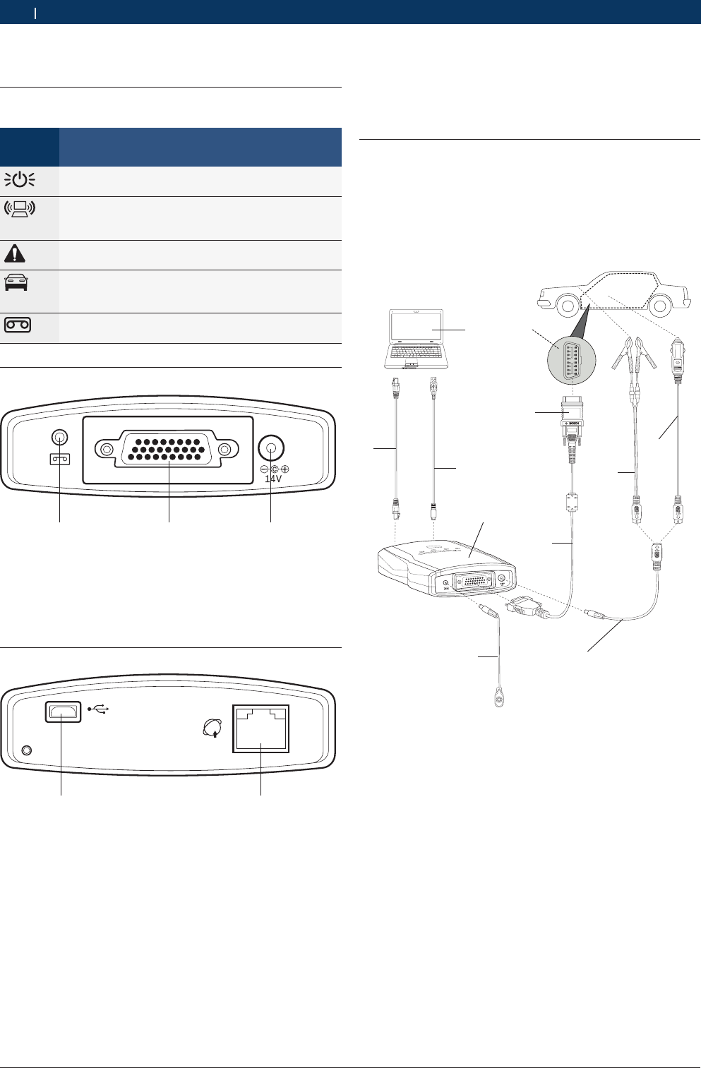
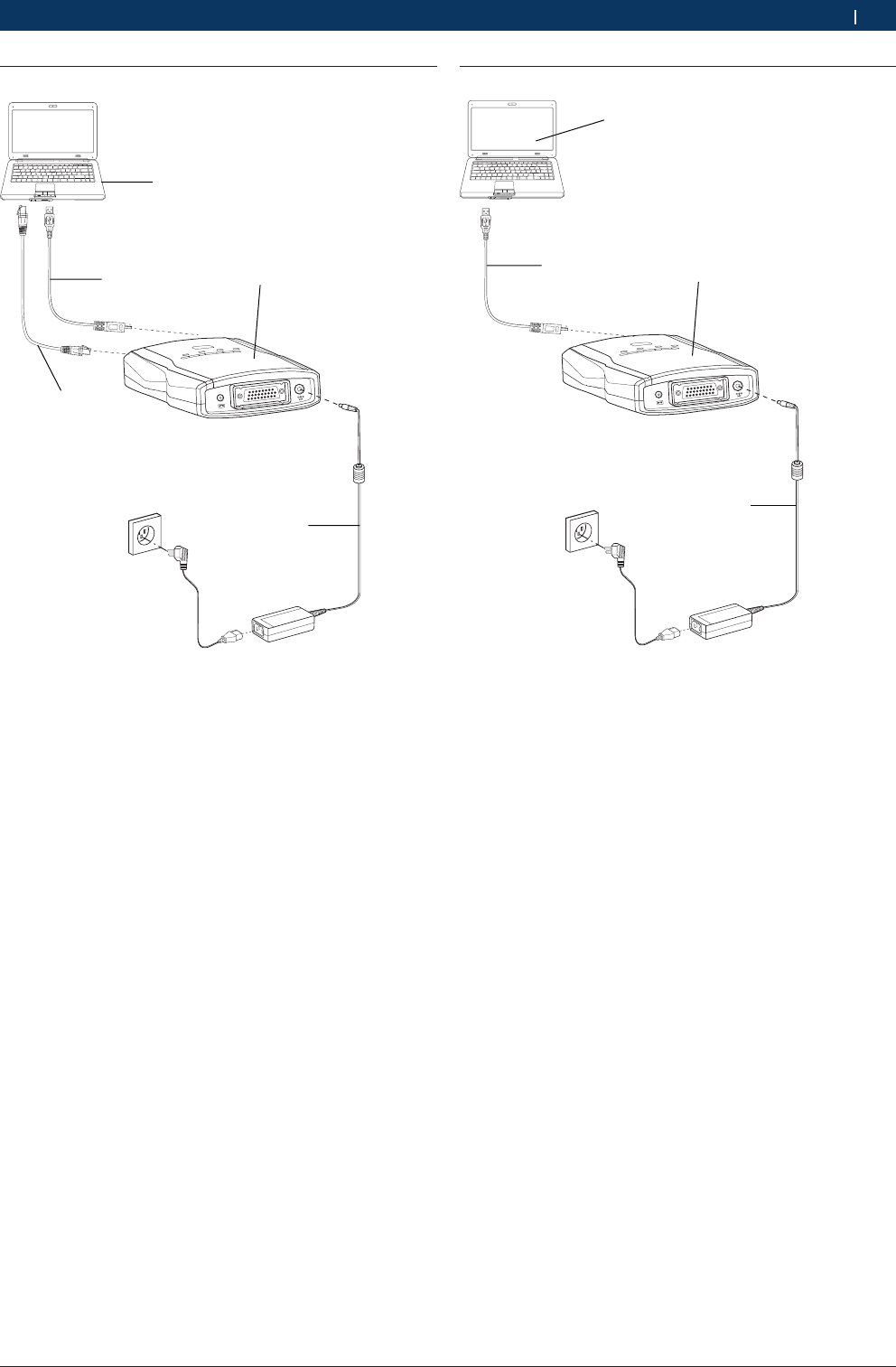
6. Equipment connection
According to different functions, the connection modes
are: including diagnostic connection, selfcheck connec-
tion and firmware upgrade connection.
6.1 Diagnostic connection
Before using the equipment, please ensure the normal
connection among the VCI, computer, and on-board
ECU. The main connection modes are: including the
USB port connection, network port connection and
wireless connection. If all connected, the USB port con-
nection is preferential.
1
2
3
4
11
10
5
9
6
7
8
V
CI
0
03
Fig. 3: Diagnostic connection
1. Interface on car
2. Connector
3. Diagnostic extension cable
4. Power extension lead
5. Record cable
6. VCI host
7. Computer
8. LAN cable
9. USB cable
10. Alligator clip
11. Cigarette igniter connector
5. Introduction to VCI host
5.1 Host identifications
Identifi-
cation
Description
The power indicator lamp, lighting in green to indi-
cate the normal power supply;
The computer communication indicator lamp, ligh-
ting in green to indicate the wired connection or in
yellow to indicate the wireless connection;
The malfunction indicator lamp, lighting in red to in-
dicate the VCI malfunction;
The ECU communication indicator lamp, lighting in
green to indicate the CAN communication mode or
in yellow to indicate other communication modes;
The travel recorder button identification, used for
your convenient and rapid operation.
5.2 Diagnosis port
DIAG
1 2 3
VCI001
Fig. 1: Diagnosis Port
1. Data record interface
2. Diagnosis interface
3. Power interface
5.3 Connection Port
1 2
VCI002
USB
Fig. 2: Connection port
1. USB communication interface
2. Network communication interface
Bosch Automotive Diagnostics Equipment (Shenzhen) Limited
Equipment connection | VCI | 15VCI | 15 | 15 en
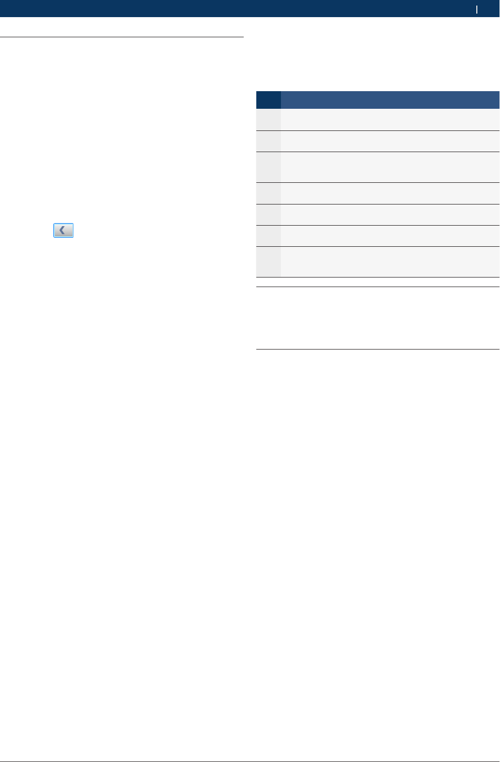
6.2 Selfcheck connection
1
2
3
4
5
V
CI
0
0
4
Fig. 4: Selfcheck connection
1. Power adapter
2. VCI host
3. USB cable
4. LAN cable
5. Computer
6.3 Firmware upgrade connection
1
23
4
V
C
I00
5
Fig. 5: Firmware upgrade connection
1. Power adapter
2. VCI host
3. USB cable
4. Computer

Bosch Automotive Diagnostics Equipment (Shenzhen) Limited
16 | VCI | Initial Start-upen
7. Initial Start-up
Upon the initial start-up, the normal use of VCI can be
achieved after setting the communication port.
If your VCI is connected with the computer through the
USB communication line, please make settings fol-
lowing descriptions in section <8.3.1.1>;
If your VCI is connected with the computer through the
network cable, please make settings following descrip-
tions in section <8.3.1.2>;
If your VCI is connected with the computer through the
wireless mode, please make settings following descrip-
tions in section <8.3.1.3>.
8. VCI system settings
8.1 System Settings
The system settings include the language settings, sys-
tem information, user information, proxy settings, pro-
duct activation.
8.1.1 Language Settings
The VCI provides the multi-language system for user to
switch languages.
Operation Steps:
1. Proceed to the language settings module and select
the target language from the “Language Type Selec-
tion” box;
2. Click the “OK” button and the interface will prompt
“Effective after System Restart”.'
3. The language settings will be effective after the
system restart.
8.1.2 System information
The system information includes the product serial
number, instrument type, machine type, software versi-
on, and activation status.
8.1.3 User information
The user information includes the contact information,
telephone number, maintenance station name, mainte-
nance station code, maintenance station address, and
remarks.
If such information is consistent with that upon prin-
ting, you can directly enter them and click the “OK”
button for saving. It is unnecessary to enter such infor-
mation upon printing.
Operation Steps:
1. Enter your information in the "*" input box marked;
2. Click "OK" button and save your informations; you
can click "Cancel" button and don't save information.
8.1.4 Proxy Settings
This function is intended to judge whether the proxy
server is required for the computer networking; if not
required, select “Don't Use the Proxy Server”.
Setting method for using the proxy server:
1. Select “Use the Proxy Server”;
2. Enter the address and port information;
3. You can set the user name and password for settings
protection;
4. Click the “OK” button.

Bosch Automotive Diagnostics Equipment (Shenzhen) Limited
VCI system settings | VCI | 17VCI | 17 | 17 en
8.1.5 Product Activation
If the product is not activated, you can only view the
test demonstration rather than carrying out the diagno-
sis with VCI.
Operation Steps:
1. Check whether your VCI host is normally connected
with the computer; If ok, the VCI software will auto-
matically detect the product serial number;
2. Please read the display information, then click "Acti-
vation" button, the software will automatically detect
the network; If not ok, display "Network connection
overtime";
3. If network is worked to proceed to the individual in-
formation filling interface; please enter your informa-
tion following the interface prompts; If information
incorrect, you must to re-enter;
4. If all information is accurate, click the “Next” button,
the interface will display "Successful product activa-
tion, software must to restart";
5. Please restart software, you can using it.
i User name is combined by letters and numbers, the
length is 3-16 characters; the password length is
6-16 characters;
i The user name is used for upgrade log-in, which
can’t be repeated, and real-name registration is
recommended; the E-mail is used for the password
retrieve, and please fill your frequently-used E-mail;
upon submitting your individual information, please
remember your user name and password.
8.2 Software upgrade
Software upgrade includes software upgrade and VCI
firmware upgrade.
This function is available only after the product activati-
on. If not, display "Not activation".
iBefore upgrade, please ensure the normal connec-
tion between the VCI and computer;
iEnsure the integrity of the upgrade process by not
forcing to terminate the program.
8.2.1 Software Upgrade
Software upgrade includes application software up-
grade and diagnostic database upgrade.
Operation Steps:
1. The software will automatically detect the version of
application software and diagnostic database;
2. If you didn't change the user name and password,
click the “New Version Detection” button to detect
the latest version; If you changed, you must to enter
user name and password at first;
3. If there have new version, the interface will display
"Download" button;
4. Click "Download" button, waiting for finished; You
can monitor download progress;
5. After successfully download, click "Install" button to
insatll upgrade package;
6. After restart software, you can using the latest soft-
ware.
iWhen you log-in, user name and password is entered
3 times, if more, you must to wait 15 minutes.
8.2.2 VCI Firmware Upgrade
If VCI firmware have new version, VCI will automatically
upgrade when you start VCI software.
Operation Steps for manual Upgrade:
1. Click "Upgrade" button, then operate according to
interface display;
2. After successfully upgrade, display "Successfully
upgrade".
i Upon the VCI firmware upgrade, the VCI can be
connected with the computer only through the USB
port;
iIf you didn't operate according to display informati-
on.

Bosch Automotive Diagnostics Equipment (Shenzhen) Limited
18 | VCI | VCI system settingsen
8.3 VCI
The VCI include VCI communication settings, VCI infor-
mation, and VCI selfcheck.
8.3.1 VCI Communication Settings
The VCI communication port settings include the USB
settings, LAN settings, and WLAN settings.
8.3.1.1 USB Settings
When the VCI is normally connected with the computer,
the system will automatically match with the available
serial port list.
Operation Steps:
1. Select a serial port name, and click the “Automatic
Connection Test” button to test the available serial
port;
2. After the test is completed, the system will automati-
cally prompt whether to save the settings;
3. Click the “Yes” button to save the successful seri-
al port and the result will be displayed in the test
result display box.
8.3.1.2 LAN Settings
The LAN settings include the P2P mode and the route
mode.
Operation Steps for P2P Mode:
1. Select the P2P mode;
2. Enter the relevant information;
3. Click the “Automatic Connection Test” button and
wait for the test completion;
4. After the test, the test result will be displayed in the
result display box.
Operation Steps for Route Mode:
1. Select the route mode;
2. Enter the relevant information;
3. Click the “Automatic Connection Test” button and
wait for the test completion;
4. After the test, the test result will be displayed in the
result display box.
8.3.1.3 WLAN Settings
The wireless network settings include the P2P mode
and the route mode.
Please ensure WLAN normally connected of computer.
Operation Steps for P2P mode:
1. Select the P2P mode;
2. Click the “Scan Network” button to search the availa-
ble wireless network;
3. Select the available wireless network, click the “OK”
button, and the interface will display the information
concerning all networks connected with the VCI;
4. Click the “Automatic Connection Test” button and
wait for the test completion;
5. After the test, the test result will be displayed in the
result display box.
Operation Steps for Route Mode:
1. Select the route mode;
2. Click the “Scan Network” button to search the availa-
ble wireless network;
3. Select the available wireless network, click the “OK”
button, and the interface will display the information
concerning all networks connected with the VCI;
4. Click the “Automatic Connection Test” button and
wait for the test completion;
5. After the test, the test result will be displayed in the
result display box.
8.3.2 VCI Information
The VCI information include the serial number and firm-
ware (VCI) software version; after the VCI is normally
connected with the computer, the system will start the
automatic detection.
8.3.3 VCI Selfcheck
This function is used to detect whether the VCI is nor-
mal.
Operation Steps:
1. Ensure normally connection between the VCI and the
computer;
2. Click the “Start Selfcheck” button and wait for the
selfcheck completion and detection result display.
iWhen VCI selfcheck, ensure disconnection between
VCI and diagnostic cable.
Bosch Automotive Diagnostics Equipment (Shenzhen) Limited
Vehicle Diagnostic | VCI | 19VCI | 19 | 19 en
8.4 Vehicle Logo Replacement
There are two vehicle logo replacement methods: single
replacement and integral replacement, with the single
replacement taken as the default mode. The picture
size is 136*115 (mm) and the picture format is bmp.
8.4.1 Single Replacement
Only one vehicle logo can be replaced one time.
Operation Steps:
1. Select “Single Replacement”;
2. Select the vehicle logo to be replaced in the left
dropdown box;
3. Select the target vehicle logo on the right;
4. Click the button in the middle to synchronize
logos at both sides; at the same time, the replace-
ment button changes to the available status;
5. Click the “Replace” button.
8.4.2 Integral Replacement
Several vehicle logos can be replaced one time.
Operation Steps:
1. Select the “Integral Replacement”;
2. Click the “Browse” button to select the target pic-
ture folder, and its path shall correspond with the
path in the CF card;
3. Click the “Replace” button.
9. Vehicle Diagnostic
Main Interface of Vehicle Diagnosis:
No. Description
①The main function area, including vehicle diagnosis, ve-
hicle analyzer and service help;
②The system function area, including screenshot, play-
back, setting, help and feedback;
③The display area for vehicle series, including All, Chinese,
American, European, Japanese, Korean, OBD-II and his-
tory record;
④The display area for testable vehicle models, including all
testable vehicle models of each vehicle series;
⑤The display area for additional functions, including brand
search;
⑥The status column, including diagnosis path, VCI connec-
tion status and VMI connection status;
⑦The scrolling bar, which can be dragged for viewing con-
tents of multiple screens when the displayable contents
are in more than one screen.
9.1 Test Conditions
RThe vehicle power switch turned on;
RThe vehicle battery voltage at 12V or 24V;
RThere is communication between the host and PC .
9.2 Power supply of host
There are 4 power supply modes for VCI host, you can
select according to your requirement:
RAC power supply: take out VCI standard configura-
tion power adapter in the instrument; Connect one
end to the power interface of the instrument and
another end to 100~240V AC socket;
RAutomobile battery cell power supply: take out
KT600 standard configuration power extension lead
and alligator clip; connect one end to the power in-
terface of the instrument and another end to battery
end;
RCigarette lighter power supply: take out VCI standard
configuration power extension lead and cigarette
lighter; connect one end to power interface and ano-
ther end to cigarette lighter;
RDiagnosis retainer power supply.
Bosch Automotive Diagnostics Equipment (Shenzhen) Limited
20 | VCI | Vehicle Diagnosticen
9.3 Selecting a Method to Access the
Diagnosis System
There are three methods available for accessing the dia-
gnosis system, i.e. Manual Selection, Brand Search and
History Record. You may select the most suitable ope-
ration method out of them depending on your available
information.
9.3.1 Manual Selection
You may manually select the corresponding vehicle mo-
del, system or system function to proceed to the diag-
nosis operation.
For example, you may: click “Chinese Vehicle Series”
--- “Chery” --- “Fulwin” ---”Engine” --- “Motorola EFI
System”, and then carry out the diagnosis test on your
desired system function.
9.3.2 Brand Search
This function searches the corresponding vehicle
brands according to the information input, but it only
supports the search by letters.
Operation Steps:
1. Enter CHANGAN in the search box.
2. Just click the button on the right to find out
the CHANGAN brand and carry out the diagnosis
test.
9.3.3 History Record
You may access your desired vehicle model or system
through the “History Record”, provided that you had
diagnosed this vehicle model or system. Only 30 latest
tested vehicle models can be saved in the “History Re-
cord”.
iFor your convenient choice, we recommend that you
use to manual selection or brand search into diag-
nostic system.
9.4 Diagnostic
9.4.1 Introduction to Main Interface of Diagnosis
System
After you access the diagnosis system, the VCI software
interface will display all diagnosis functions that can be
achieved by this system.
No. Description
①The display area for diagnosis functions: it shows all dia-
gnosis functions of this system;
②The display area for help information: it shows the help
information of a diagnosis function and supports both li-
teral and graphic information.
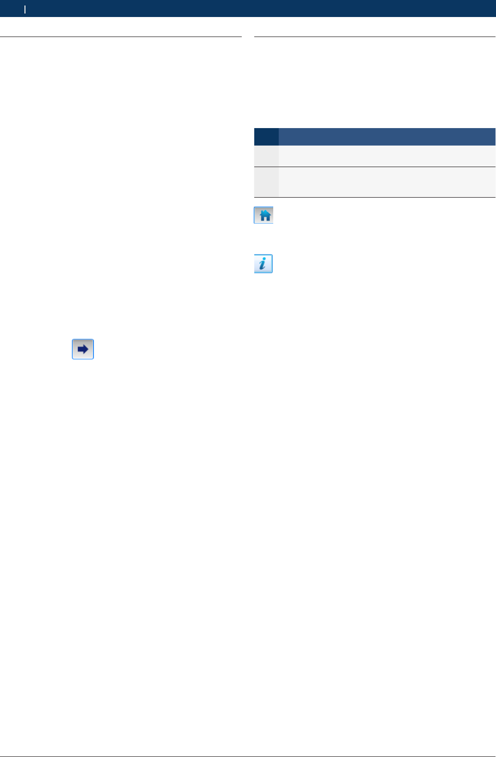
: Click this button to go back to the main interface.
You can find this button on display of select menu, read
DTC and read data stream.
: Diagnostic help button, if there have help informa-
tion, the button will display. Otherwise not display.
9.4.2 Reading Version Information
This function is used to read the computer information
of the system being tested. The information read varies
with different vehicle models or systems. Generally,
when you replace the vehicle control unit, it is neces-
sary to read and record the information of original
control unit and take such information as a reference
for purchasing a new control unit. Coding a new control
unit requires the information of original control unit.
Operation Steps:
1. After proceeding to the diagnosis function, click
“Read Version Information” to get a pop-up dialogue
box, which shows the relevant information of vehicle
computer such as software version, hardware versi-
on and part numbers.
2. Click the “OK” button to quit this function.
Bosch Automotive Diagnostics Equipment (Shenzhen) Limited
Vehicle Diagnostic | VCI | 21VCI | 21 | 21 en
9.4.3 Reading DTC
This function is used to read the fault code in the ECU
memory of the system being tested, helping the service
personnel quickly find out the cause of vehicle fault.
Operation Steps:
1. After proceeding to the diagnosis function, click
“Read Fault Code”.
2. Open the fault code interface to view the fault code
items, including content, status (current or random),
freeze frame and help.
3. Click the “Exit” button to quit this function.
iIf the system being tested is normal, the interface
will display “System OK” and the button “Clear Fault
Code” will not appear on the interface.
iIf the fault code has some freeze frame or help
information, its icon is blue. Or else, its icon is gray,
which means unavailable.
iButton Description:
Button Description
Reading the freeze frame information; when it is dis-
played in grey, this means there is no freeze frame in-
formation;
The help information for fault code; when it is dis-
played in gray, this means there is no help information;
Clearing the fault code, see 9.3.4; if the system being
tested is normal, this button will not appear on the
current interface;
Refreshing the current fault code; after eliminating so-
me faults, you may click this button to refresh the exis-
ting fault codes.
9.4.3.1 Help Information for DTC
It is used to display the help information for the opposi-
te fault code.
Operation Steps:
¶Select a fault code, and click the “Help Information
for Fault Code” button. Then the interface will show
the help information for this fault code, helping the
service personnel quickly find out and solve the
problem.
iThis interface is an independent window, regardless
of the diagnosis software.
9.4.3.2 Reading Freeze Frame
In the engine management system, the freeze frame
function is supplementary to the fault code function.
It is basically used to freeze the relevant working con-
ditions of engine when engine fault arises, helping the
service personnel know the working conditions of the
whole vehicle upon the fault occurrence.
Operation Steps:
1. Select a fault code, and click “Read Freeze Frame
Information” to proceed to the corresponding inter-
face. Each freeze frame can display a maximum of 5
groups of data;
2. Click the “Exit” button to quit this function.
iYou may also proceed to this function through the
“Read Freeze Frame” button at the diagnosis func-
tion area, but then only the freeze frames for com-
mon data streams can be read and generally only
one group of data will be displayed.
9.4.4 Clearing DTC
It is used to clear the DTC saved in the ECU memory of
the system being tested.
Operation Steps:
1. After proceeding to the diagnosis function, click
“Clear Fault Code” to get the dialogue box, which
displays the clearing conditions.
2. After the completion of fault code clearing, the inter-
face will display “Clearing Command Executed”;
3. Click the “OK” button to quit this function.
iFor the common vehicle models, you shall strictly
comply with the following regular work procedures:
firstly, read, record (or print) and clear the fault
codes; then, test the vehicle, and re-read the fault
codes for verification; next, service the vehicle and
clear the fault codes; finally, re-test the vehicle and
confirm that the fault codes are no longer present;
iIt is impossible to immediately clear any current hard
fault code. Although such technical fault codes invol-
ving oxygen sensor, knock sensor, mixture correction
and cylinder misfire can be immediately cleared,
they would reappear within a certain period. Only
after the fault has been completely eliminated will a
fault code never reappear.
Bosch Automotive Diagnostics Equipment (Shenzhen) Limited
22 | VCI | Vehicle Diagnosticen
9.4.5 Reading Data Stream
By means of values or conditions of data streams, this
function can identify whether the vehicle components
are faulty.
Operation Steps:
1. After proceeding to the diagnosis function, click
“Read Data Stream” to get the “Read Data Stream”
dialogue box;
2. Click the “Select All” check box to select all data
streams; also, you may only click the check boxes
in front of data streams to select the desired data
streams;
3. Click “Read Data Stream” to view names, results and
units of data streams;
4. Click the “Exit” button to quit this function.
iWhen you are reading the data streams, the “Pause”
button can be clicked to provide convenience for you
to view the results of data streams. Once clicked, the
“Pause” button will switch to the “Resume” button.
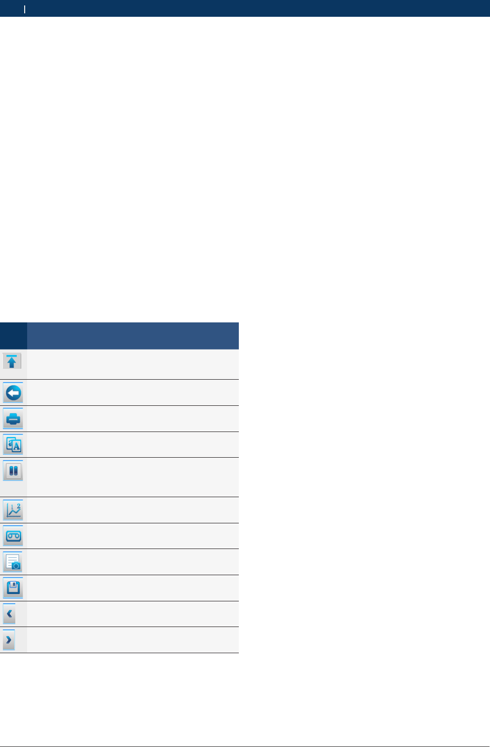
iButton Description:
But-
ton
Description
The “Top” button; to set a data stream to the top for
display, click this button in front of this data stream; to
cancel the setting, click this button again;
The “Exit” button, used to quit the function “Read Da-
ta Stream”;
The “Print” button, see <9.5.1>;
The “Compare Data Streams” button, see <9.4.5.2>;
The “Pause/Resume” button; when clicked during the
course of reading data streams, it pauses the reading
and switches to the “Resume” button; to resume the
reading, click the “Resume” button;
The display mode of data stream, see <9.4.3.5>;
The “Travel Recorder” function, see <9.4.6>;
The “Capture Data Streams” function, see <9.4.5.1>;
The “Save Data Streams” function, see <9.4.5.3>;
Viewing the previous page of data stream;
Viewing the next page of data stream;
9.4.5.1 Capturing Data
It records the data stream being tested.
Operation Steps:
1. Click the “Capture Data” button and start to record
the current value of data stream; you may turn the
pages to record all data streams. If you do not turn
the pages, only the data stream displayed in the
current screen will be recorded;
2. Click the “Save” button to save the data stream read.
iBefore you activate the “Capture Data” function, the
“Save” button is gray, which means unavailable.
9.4.5.2 Comparing Data Streams
By means of comparing the current values of data
streams with the saved history values of data streams,
this function can identify whether the relevant compo-
nents present a good working condition.
Operation Steps:
1. Click the “Compare” button to get the dialogue box
which displays all openable data stream files.
2. Select a data stream file and click the “Open” button
to get the interface which displays the current read
values and recorded history values.
iThe data stream save path is assigned by the sys-
tem and cannot be modified; the current values are
displayed in black, while the recorded history values
are in green;
iIn the opened dialogue box, you may delete the un-
necessary data files which are previously saved;
iThe “Save” button will switch to the “Clear” button.
9.4.5.3 Saving Data
This function is used to save the values of all currently
captured data streams.
Operation Steps:
1. Click the “Save” button to get the “Save” dialogue
box, in which the save path is assigned by the sys-
tem and cannot be modified;
2. Enter the file name and click “Save”; then, the inter-
face will display “Data Saved”.
3. Click "OK" to complete the saving of data streams;
then, the “Save” button will go gray, which means
unavailable.

Bosch Automotive Diagnostics Equipment (Shenzhen) Limited
Vehicle Diagnostic | VCI | 23VCI | 23 | 23 en
9.4.5.4 Clearing Data
This function is used to clear the comparison between
data streams.
Operation Steps:
¶Click the “Clear” button to clear the history values
of data comparison; meanwhile, the “Clear” button
switches to the “Compare” button.
9.4.5.5 Display Modes of Data Streams
The value of a data stream can be displayed in three
modes, i.e. numeral, waveform and control. The nume-
ral display mode is taken as a default.
Operation Steps:
1. After reading the data streams, the values of read
data streams will be displayed in numerals;
2. Click the “Numeral” button and select "Waveform"
from the pop-up options; then the values of data
streams will be displayed in waveforms, and the “Nu-
meral” button will switch to the “Waveform” button;
3. Click the “Waveform” button and select "Control"
from the pop-up options; then the values of data
streams will be displayed in controls and the “Wave-
form” button will switch to the “Control” button;
4. Click the “Control” button and select "Numeral" from
the pop-up options; then the values of data streams
will be displayed in numerals and the “Control” but-
ton will switch to the “Numeral” button.
iThe button status switches in compliance with the
mode in which the current data streams are dis-
played.
9.4.6 Travel Recorder
The travel recorder is mainly used to record some data
of ECU for a long time. Each data is continuous recor-
ding up to 2 hours. During the course of recording,
it can save the data at any time and save them in the
“.REC” format under the specified folders.
You may click the “Travel Recorder” button at the
“Read Data Stream” interface to proceed to the “Travel
Recorder” interface.
Parameter Description:
$Period: according to the period you select, the
system will automatically match it with the selec-
table data streams; the system provides 3 optio-
nal periods, i.e. 250 ms, 500 ms and 1000 ms; the
default period is 250 ms;
$Maximum Records: according to the period, the
system will automatically match it with maximum
records.
$Record Time: it can be manually set to 10 min
as a minimum and 120 min as a maximum; the
default record time is 120 min;
$Trigger Time: it can be manually set to 20 s as a
minimum and 120 s as a maximum; the default
trigger time is 20 s.
Operation Steps:
1. Select the period you desire;
2. Select the record time you desire;
3. Select the trigger time you desire;
4. Select the desired data stream to be recorded; if you
don’t select a data stream, the system will pop up a
warning dialogue box after you press the “Record”
button; if the selected data streams outnumber the
displayed maximum records, the system will also
pop up a warning dialogue box;
5. Click the “ ” button to start recording;
6. Click the “Record” button to stop the recording;
enter the file name in the pop-up dialogue box, and
click "Save" to save the currently recorded data.
iTrigger Records: when you click this button, the VCI
will automatically save the data streams within the
trigger time to the fixed default paths of system; this
function supports the data stream playback;
iHow to start recording (on the premise that you have
proceeded to the software interface of travel recor-
ding function):
$Click the “Record” button on the software inter-
face of travel recording function;
$Press the “Record” button on the VCI host;
$Correctly connect one end of recorder cable to
the VCI host, and press the button on the other
end of recorder cable;
iHow to use the recorder cable: hold on (i.e. the buz-
zer continuously sounds for 3 times) to start/stop
the travel recording function; press it short (i.e. the
buzzer sounds once) to trigger the record;
iThe save paths for the recorded data are system
defaults and cannot be modified.
iYou may monitor the data record time by the time
progress bar on the screen.
Bosch Automotive Diagnostics Equipment (Shenzhen) Limited
24 | VCI | Vehicle Diagnosticen
9.4.7 Playing Back Data Stream
Playing back the saved data streams is helpful for time-
ly finding out faults.
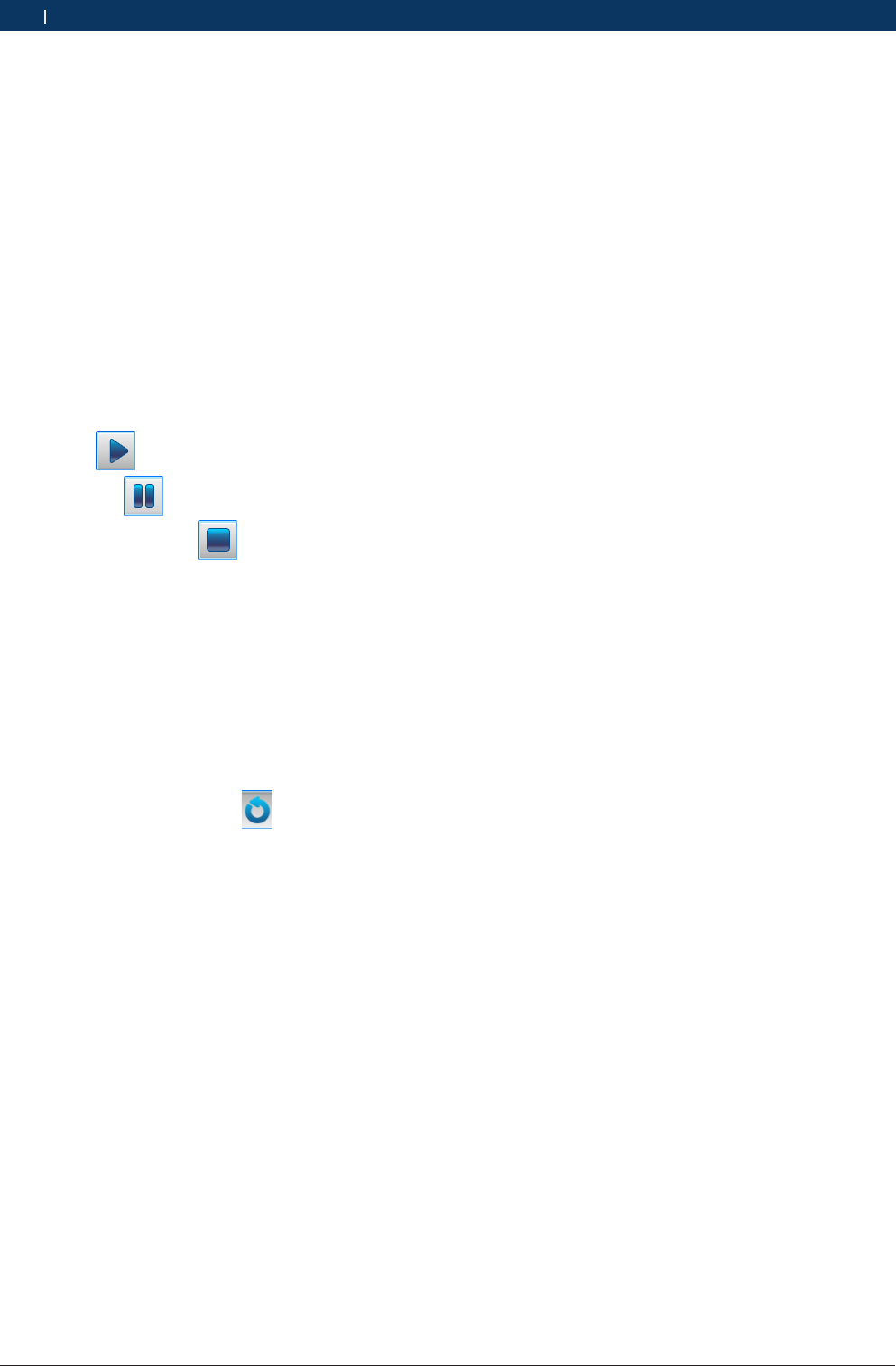
Button Description:
RExit: quit the travel record playback;
RLoad: load the data stream record to be played back;
RExport: after loading the data stream playback, the
system can export the data stream playback and
save it in the “CSV” format to the assigned path;
Operation Steps:
1. After saving the data stream record, the “Load”
button automatically becomes available. Now, click
“Load”, and select the data file you want to play
back;
2. Click the (“Play”) button.Now, the “Play” button
switches to the (“Pause”) button;
3. You may also click the (“Stop”) button to stop
the data stream playback and carefully observe whe-
ther the data stream is normal;
4. If you want to export the data stream playback, you
just need to select a folder directory and click the
button “Save”. The file will be saved in the “.CSV”
format to the path as assigned.
5. Click "Exit" to quit the “Play Back Data Streams”
function.
iYou may also proceed to the “Play Back Data
Streams” function through the (“Playback”) button
at the main interface of software;
iThe software interface provides a time progress bar,
through which you can view the duration of current
playback.
9.4.8 Action Test
This function is used to test whether the executive ele-
ments and components of electronic control system
can work normally.
Operation Steps:
1. After proceeding to the diagnosis function, select
“Action Test”. Now, the interface will display all
available action tests.
2. Click a test item to proceed to the action test inter-
face. There are three modes for the action test, i.e.
Enable, Disable and Exit;
3. Click “Enable” to activate the action test;
4. Click “Disable” to deactivate the action test;
5. Click “Exit” to quit the action test.
9.4.9 Advanced Functions
The advanced functions (such as Write IQA Codes and
Reset Maintenance Lamps) are functions other than the
basic ones and can modify the internal information of
ECU.
Operation Steps:
¶Proceed to an advanced function, and operate as per
the interface prompts till the completion.

Bosch Automotive Diagnostics Equipment (Shenzhen) Limited
Vehicle Diagnostic | VCI | 25VCI | 25 | 25 en
9.5 Other Functions Related to Diag-
nostic
9.5.1 Print
The “Print” function provides three options, i.e. “Print
Current Screen”, “Print Detection Record” and “Print
Diagnosis Report”.
Print Modes:
RPrint: if the computer has been connected with a
printer, direct print is available; or else, you can only
preview the information to be printed.
RPrint to File: see 9.5.1.4.
9.5.1.1 Print Current Screen
It is used to print the content displayed in the current
screen.
Operation Steps:
1. Select “Print” --- “Print Current Screen”;
2. Just select a print mode (either “Print” or “Print to
File”) to start printing.
i When you select “Print Current Screen”, it is un-
necessary to enter any information, and all informa-
tion displayed in the current screen will be directly
printed.
9.5.1.2 Print Detection Record
It is used to print the current detection information.
Operation Steps:
1. Select “Print” --- “Print Detection Record”; only after
detection functions (such as “Read Fault Codes”,
“Read Data Streams” and “Read Version Informati-
on”) have been enabled can this button be available;
or else, this button will be gray, which means una-
vailable;
2. Fill in the corresponding blanks with the information
relevant to detection record; any blank marked with
“*”must be filled in, otherwise it is impossible to
print the detection record;
3. Just select a print mode (either “Print” or “Print to
File”) to start printing.
9.5.1.3 Print Diagnostic Report
It is used to print the diagnostic report.
Operation Steps:
1. Select “Print” --- “Print Diagnosis”; only after any of
the functions (i.e. “Fault Codes”, “Data Streams” and
“Version Information”) has been enabled can this
button be available; or else, this button will be gray,
which means unavailable;
2. Select the diagnosis report(s) to be printed; it is
available to simultaneously print the diagnosis re-
ports on Version Information, Fault Codes and Data
Streams, provided that such three functions have
been enabled; if merely the “Read Version Informati-
on” function has been enabled, then the Fault Codes
and the Data Streams will be gray and cannot be
printed;
3. Fill in the corresponding blanks with the information
relevant to diagnosis report; any blank marked with
“*”must be filled in, otherwise it is impossible to
print the diagnosis report;
4. Just select a print mode (either “Print” or “Print to
File”) to start printing.
9.5.1.4 Print to File
5. It is used to print the desired content into an image
file in the “JPG” format.
Operation Steps:
1. Select “Print to File” to get a pop-up dialogue box
for saving;
2. Select the save path for the file;
3. Enter the file name;
4. Finally, click the “Save” button.
Bosch Automotive Diagnostics Equipment (Shenzhen) Limited
26 | VCI | Vehicle Diagnosticen
9.5.2 Image Browse
It provides convenience for you to browse images.
Operation Steps:
¶Double click the image to proceed to the “Image
Browse” function.
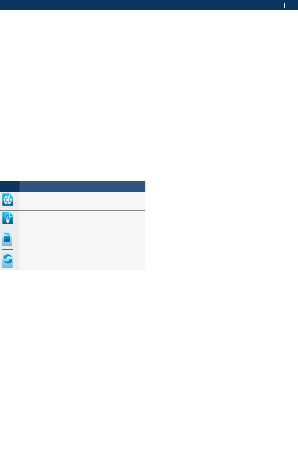
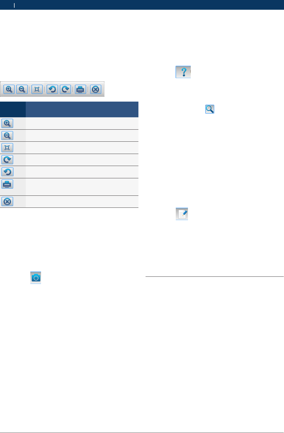
iToolbar Description:
Identifica-
tion
Description
The “Zoom In” button, used to zoom in the
browsed image;
The “Zoom out” button, used to zoom out the
browsed image;
The “Restore” button, used to restore the browsed
image to its original size;
The “Clockwise Rotate” button, used to rotate the
browsed image clockwise;
The “Counterclockwise rotate” button, used to ro-
tate the browsed image counterclockwise;
The “Print” button, used to directly print the image
into a file, provided that the computer has connec-
ted with a printer;
The “Close” button, used to close the image brow-
se tool.
9.5.3 Screenshot
It is used to capture the information of current window,
and the system will save the information as a file in
the “JPG” format under the default path (e.g. KT700/
SCREENSHOTS/); such a file cannot be modified, and
its name is automatically assigned by the system.
Operation Steps:
1. Click the (“Screenshot”) button from the left
top of screen; the system automatically saves the
file, and the interface displays the save path and the
name of this file.
2. Click the “OK” button to quit the function “Screens-
hot”.
9.5.4 Help
It is the on-line help function for the VCI, telling you
how to operate the VCI and how to implement the diag-
nosis. It works as an independent interface.
Operation Steps:
1. Click the (“Help”) button on the main inter-
face of system to proceed to the “Help” interface;
2. You may view the desired content through the navi-
gation bar on the right;
3. You may also use the (“Search”) button to enter
the keyword and view the desired content.
iFor easy and fast search, you may place the items
frequently viewed into the “Favorite” folder; you may
print the content displayed in the current page.
9.5.5 Feedback
The VCI provides the on-line feedback function by
which you can feed back any problem found during the
diagnosis, provided that your computer has connected
with the Internet.
Operation Steps:
1. Click the (“Feedback”) button on the main
interface of system to get a pop-up feedback infor-
mation interface;
2. If your VCI has been registered, the system will au-
tomatically check the customer information, vehicle
information and KT information, and you just need to
provide the fault information;
3. Just click the “OK” button to submit your feedback.
9.6 Service Help
This function, specially provided by Bosch Automotive
Diagnostics Equipment (Shenzhen) Limited, is the help
information on vehicle service and can be used as a
reference for the service personnel.
Bosch Automotive Diagnostics Equipment (Shenzhen) Limited
Service and Maintenance | VCI | 27VCI | 27 | 27 en
10. Service and Maintenance
10.1 Cleaning
It is not recommended to clean the VCI host with the
corrosive detergent or any coarse cloth; only the soft
cloth and neutral detergent can be used.
10.2 Maintenance
RPlace the VCI in the flat and dry place with moderate
temperature and less dust when the VCI is not used;
RDon’t place the VCI in the place with direct sunlight
or close to the heating device;
RDon’t place the VCI near the stove or in the place
where will be easily subjected to smoke erosion,
water entry, and oil splashing;
RDon’t disassemble the host without permission;
RIf the vehicle test is not performed for a long time,
please periodically run the VCI host to avoid being
affected with damp.
11. Technical Parameters
11.1 Host Parameters
Item Index
Size 175*115*51(mm)
Host Weight Approximately 330g
External power supply 100V~240V/50~60HZ
Power <5W
Working temperature -10~45°C
Storage temperature -15~50°C
Relative humidity <95%
Input voltage DC 7~32V
USB Micro USB-B
LAN 10M/100M ethernet card
KEY Recorder key
LED 4 LED indicator lamps indicating the
working status
CPU FREESALE 16BIT microprocessor
WLAN 802.11b
Diagnosis switch array FULL for SAE J1962
Protection grade IP31
External battery Optional
12. Warranty
RHost warranty period within 12 months from the
date of activation(within 24 months from the date of
manufacture); Accessories warranty period within 6
months from the date of their host activation(within
12 months of the date of manufacture);
RCompany supply free maintenance if product dama-
ged under normal operation within guarantee time
The following cases are not included, we will charge
material cost or other relative fees:
$Damage due to improper operation or accident;
$Remove and repair without technical people's
advice;
$Components damaged or wear out naturally;
$Encounter force majeure such as disaster.
RInstrument itself is the limit of our maintenance
service. For damage excpet that, we will not take
responsibility.

EU Declaration of Conformity
according to the Radio Equipment and
Telecommunications Terminal Equipment Directive
1999/5/EC
For the following equipment
Product :
Vehicle Diagnosis
Type Designation/Trademark :
KT700VCI
Manufacturer’s Name :
Bosch Automotive Diagnostics Equipment
(Shenzhen) Limited
Manufacturer’s Address :
5/F,A, Gardon City Cyber Port, Nanhai Road
No.1079, Nanshan District,
Shenzhen 518067 P.R. China
is herewith confirmed to comply with the requirements set out in the Council
Directive1999/5/EC for radio equipment and telecommunications terminal equipment.
For the evaluation of the compliance with this Directive, the following standards
were applied:
Safety: EN 61010-1:2010
Health: EN 62311 : 2008
EMC : EN 301 489-1 V1.9.2
EN 301 489-17V 2.1.1
EN61326-1: 2006
EN 61000-3-2:2006+ A1:2009+ A2:2009
EN 61000-3-3:2008
Radio: EN 300 328 V1.9.1
Responsible for making this declaration is the:
Manufacturer Authorised representative established within the EU
Person responsible for making this declaration
Name, Surname : Shensong.Li
Position/Title : Hardware Testing Engineer
China 2012.7.2
(Place) (Date) (Company stamp and legal signature)


Bosch Automotive Diagnostics Equipment(Shenzhen) Limited
5/F,A,Garden City Cyber Port, Nanhai Road No.1079,
Nanshan District, Shenzhen
518067
China
400 000 5109
www.bosch-diagnostics.com.cn