Bosch Security Systems 012 RADION Door Window Sensor ZB User Manual
Bosch Security Systems, Inc. RADION Door Window Sensor ZB Users Manual
Users Manual
The detector requires 1 battery to operate, which is
pre-installed in the detector.
Powering up the detector:
• Remove the battery isolation pull tab from the
back of the detector. The detector powers up,
and the green LED lights. The detector enters
pairing mode when the green LED begins
flashing 3 times every 5 seconds. Continue
with Section 4.1, Pairing process.
4 | Installation
The LED provides feedback during installation or
test mode.
4.2 | LED behavior
LED Condition
Flashing • Flashes at a variable rate indicates
magnetic field strength
• Flashes 3 times every 5 seconds
during a 2 minute interval
indicates pairing mode
Green Good wireless signal strength
performance
Red Poor wireless signal strength
performance
Off • Normal operation and use
• Optimal magnet gap distance
• 90 seconds of inactivity during
test mode
4.1 | Pairing process
NOTICE!
Verify that the home automation or
security system is powered up and
operating. Then, put the system or
control panel into pairing mode.
Pairing the detector with the controller:
1. With the detector in pairing mode (green LED
flashing after powering up), go to the home
automation or security system and complete
the pairing process according to the system
manufacturer’s instructions. The manufacturer
enrollment process might require additional
time for discovery, moving the magnet, or
tampering the detector (open and close
detector cover) to trip the detector and re-enter
pairing.
2. When pairing is complete, the detector enters
test mode, and is ready for installation.
Identify and test desired mounting locations
before you permanently install the detector
and magnet. Refer to Section 3 for installation
guidelines.
Mounting the detector and magnet:
1. Ensure the detector is in test mode.
2. Select a location for the detector on a
stationary surface of an interior door or
window frame.
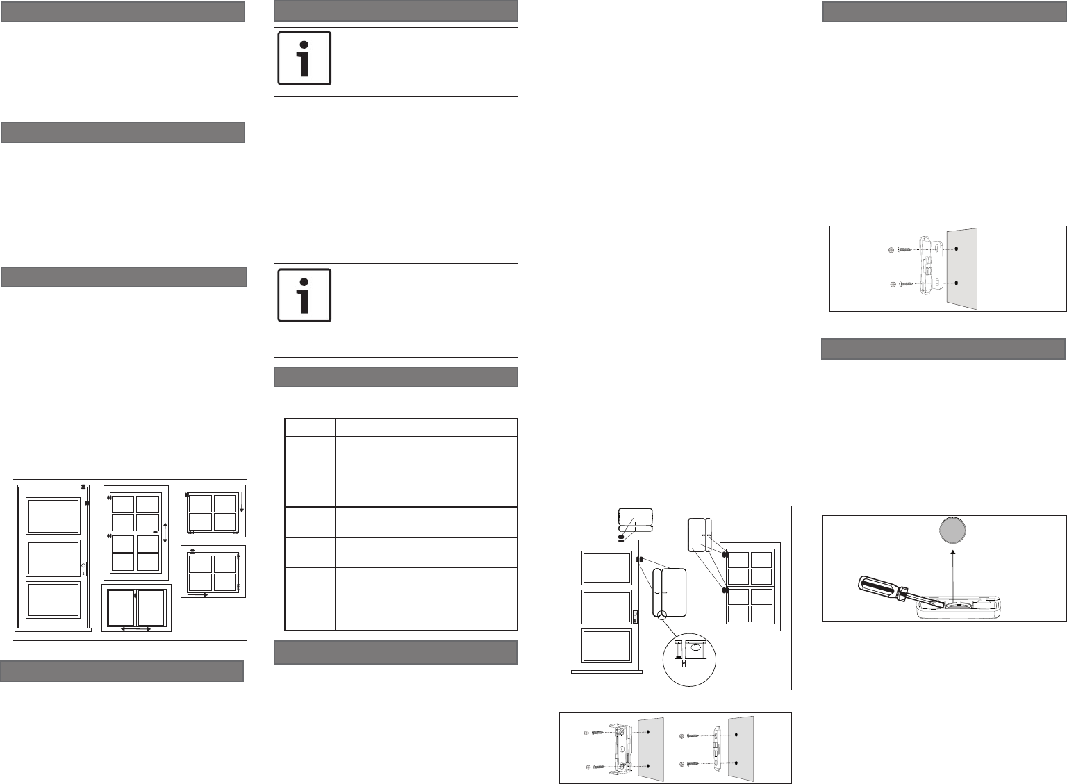
4.3 | Mounting and testing
Figure 4.1: Correct alignment and placement
Figure 4.2: Detector and magnet mounting with
screws
4.5 | Thin window mounting
Use this procedure for special applications, such
as thin windows where the magnet cover may
prevent the window from opening.
Installing on thin windows:
1. Remove the base of the magnet by inserting
a small flat head screwdriver or similar tool in
the slots on either end of the magnet base and
carefully pry off.
2. Pry out the enclosed magnets from the magnet
cover using a small flat head screwdriver or
similar tool. See Figure 4.4.
4.4 | Bracket mounting
The mounting bracket allows mounting of the
magnet on its left or right side (90°), instead of
its base. For example, use the mounting bracket
for installations where the detector is mounted to
the inside of a door frame. Refer to Figure 4.3.
Using the mounting bracket:
1. Remove the base of the magnet by inserting
a small flat head screwdriver or similar tool
in the slots on either end of the magnet base
and carefully pry off.
2. Push the magnet cover onto the bracket.
3. Add a tape strip to the bottom of the bracket
4. If using screws, mount the bracket first, then
replace the magnet cover. Refer to Figure 4.3.
The exception is double hung windows, where
the detector is mounted to a moving sash.
Temporarily mount the detector.
3. Place the magnet near the detector and move
it to the desired mounting location, making
sure the alignment marks on the detector
and magnet align. Place the magnet and
detector side by side, and as close together
as possible. The LED flash rate indicates the
strength of the magnetic field. The LED turns
off at the optimal placement of the magnet to
the detector. Temporarily mount the magnet.
The recommended magnet gap distance is
0.75 inches (19.05 mm).
4. To verify proper wireless signal strength, open
the door or window and check the color of the
LED. If the LED is green, the signal strength
is acceptable. If the LED is red, reposition the
magnet and detector, then recheck the LED
color. When the device RSSI (Received Signal
Strength Indicator) or LQI (Linked Quality
Indicator) level is poor, the LED is red. Refer
to Section 4.2, LED Behavior.
5. Open the door or window to test for proper
clearance, and alarm operation. When the
distance between the detector and magnet is
greater than or equal to 1.3 inches (33 mm),
the alarm triggers.
6. When the location is acceptable, permanently
mount the detector and magnet using the
double-sided tape on the base. If using screws
for mounting, remove the detector and magnet
covers to access the mounting holes. You may
have to remove the tape on the bottom of the
detector and magnet bases to mount flush
on the surface. Refer to Figure 4.2 for surface
mounting, Section 4.4, and Section 5 for
removing the magnet and detector covers. For
additional security, use an adhesive with the
screws when mounting.
Figure 4.3: Mounting bracket using screws
</= 3.0 cm
(1.3 in)
3. Remove the round perforated section of tape
from the base of the detector.
4. Attach the round section of tape to 1 magnet
and place the magnet on the window opposite
the detector. Use the alignment mark on the
detector to align and center the magnet with
the detector.
Figure 4.4: Remove magnet from magnet cover
NOTICE!
If the system does not discover the
detector within 2 minutes, the detector
exits pairing mode. Restart pairing
mode by either opening/closing the
detector cover, moving the magnet, or
powering the detector off, then on.
Figure 3.1: Door/window installation locations
3 | Installation considerations
– Suitable flat surfaces for installation include
wood, metal, vinyl, glass, and painted surfaces.
– Installation on metal surfaces can affect the
wireless propagation pattern of the radio
transceiver.
– Verify proper clearance with the latch of the
window or door and the detector. Failure to do
so might make it difficult to access and open the
detector for maintenance.
– Moving the home automation or security system
may improve wireless communication range
performance. In some instances, installing
another device, such as a repeater, might be
required.
2 | Product contents
The product box contains:
– 2 detectors with installed batteries
– 2 magnets
– 2 mounting brackets
– 2 tape strips for mounting brackets
– Installation instructions
The RADION contact ZB Door Window Detector is
a surface-mount wireless detector for monitoring
door or window position (open or closed). The
ZigBee® compatible radio allows connection
to a security or home automation system. The
detector also monitors temperature, and includes
tamper detection.
1 | Overview
PRELIMINARY
© 2017 Bosch Security Systems, Inc. F.01U.330.365 | 00e | 2017.03
en Installation Manual
fr Guide de l’installateur
Bosch Security Systems, Inc.
130 Perinton Parkway
Fairport, NY 14450
USA
www.boschsecurity.com
Bosch Sicherheitssysteme GmbH
Robert-Bosch-Ring 5
85630 Grasbrunn
Germany
RADION
contact ZB Door Window Detector
RFDW-ZBMS
Copyright
This document is the intellectual property of Bosch
Security Systems, Inc. and is protected by copyright.
All rights reserved.
Trademarks
All hardware and software product names used in this
document are likely to be registered trademarks and
must be treated accordingly.
Bosch Security Systems, Inc. product manufacturing
dates
Use the serial number located on the product label
and refer to the Bosch Security Systems, Inc. website
at http://www.boschsecurity.com/datecodes/.
FCC
This device complies with part 15 of the FCC Rules.
Operation is subject to the following two conditions:
(1) This device may not cause harmful interference, and
(2) this device must accept any interference received,
including interference that may cause undesired
operation.
This equipment has been tested and found to comply
with the limits for a Class B digital device, pursuant
to part 15 of the FCC Rules. These limits are designed
to provide reasonable protection against harmful
interference in a residential installation. This equipment
generates, uses and can radiate radio frequency energy
and, if not installed and used in accordance with the
instructions, may cause harmful interference to radio
communications. However, there is no guarantee that
interference will not occur in a particular installation.
If this equipment does cause harmful interference to
radio or television reception, which can be determined
by turning the equipment off and on, the user is
encouraged to try to correct the interference by one or
more of the following measures:
– Reorient or relocate the receiving antenna.
– Increase the separation between the equipment and
receiver.
– Connect the equipment into an outlet on a circuit
different from that to which the receiver is connected.
– Consult the dealer or an experienced radio/TV
technician for help.
IC
Under Industry Canada regulations, this radio
transmitter may only operate using an antenna of a
type and maximum (or lesser) gain approved for the
transmitter by Industry Canada.
To reduce potential radio interference to other users,
the antenna type and its gain should be so chosen
that the equivalent isotropically radiated power
(e.i.r.p.) is not more than that necessary for successful
communication.
Le présent appareil est conforme aux CNR d’Industrie
Canada applicables aux appareils radio exempts
de licence. L’exploitation est autorisée aux deux
conditions suivantes : (1) l’appareil ne doit pas produire
de brouillage, et (2) l’utilisateur de l’appareil doit
accepter tout brouillage radioélectrique subi, même
si le brouillage est susceptible d’en compromettre le
fonctionnement.
Conformément à la réglementation d’Industrie Canada,
le présent émetteur radio peut fonctionner avec une
antenne d’un type et d’un gain maximal (ou inférieur)
approuvé pour l’émetteur par Industrie Canada.
Dans le but de réduire les risques de brouillage
radioélectrique à l’intention des autres utilisateurs, il
faut choisir le type d’antenne et son gain de sorte que
la puissance isotrope rayonnée équivalente (p.i.r.e.) ne
dépasse pas l’intensité nécessaire à l’établissement
d’une communication satisfaisante.
9 | Specifications
Frequency
(operating)
2.4 GHz
Max power
transmitted
20 dBm
Battery
replacement
(1 per
detector)
3 VDC ≥ 750mAh
Energizer CR2 Lithium
Duracell Ultra CR2 Lithium
Panasonic CR2 Lithium
Sanyo CR2 Lithium
Battery life ≥ 5 years with 16 open/close
alarm events per day
Dimensions
(detector)
1.8 in. x 0.92 in. x 0.79 in.
(46.0 mm x 23.5 mm x 20.3
mm)
Dimensions
(magnet)
1.8 in. x 0.32 in. x 0.79 in.
(46.0 mm x 8.3 mm x 20.3 mm)
Temperature
(operating)
-4°F to +122°F
(-20°C to +50°C)
Storage
temperature
14°F to +131°F
(-10°C to +55°C)
Relative
humidity
5% to 93% at +32°C (+90°F)
Magnet
gap break
distance
≥ 1.3 in. (33 mm) mounted to
metal, vinyl, or wood
Agency Certification
Control No.3170792
Conforms to ANSI/UL Std. 634
ULC/ORD-C634-86
FCC FCC ID: T3X-012
IC IC ID: 1249A-012
This ZigBee® Certified product
works in global 2.4 GHz networks
supporting ZigBee HA 1.2.1.
ZigBee® Certified is a registered
trademark of the ZigBee Alliance.
ZigBee® Cert No.xxx
8 | Certifications
7 | Troubleshooting
A trouble status reported on the controller might
be the result of low batteries on the detector. To
trouble-shoot the condition, begin by replacing
the batteries. Refer to Section 5 for replacing the
batteries.
Monitor the LED for issues when pairing or
mounting the detector and magnet. The LED
flashing pattern indicates wireless strength or
magnetic field strength depending on color. Refer
to Section 4.2 for LED behavior.
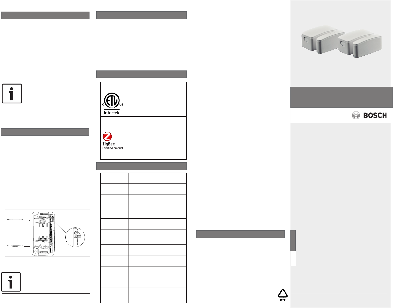
_
+
CR2
Figure 6.1: Tamper switch and battery
orientation in detector
Resetting the detector:
1. Open the detector and remove the battery.
Refer to Section 5 for opening the detector.
2. Push and hold the tamper switch, and reinsert
the battery. When the green LED turns on,
release the tamper switch before the green
LED turns off (within 4 seconds). Refer to
Figure 6.1.
3. The LED turns off, then turns on for 2
seconds, and starts the pairing sequence
(indicated by 3 LED flashes). The detector is
now reset to factory defaults. See Section 4.1
for pairing process.
4. Close the cover. Refer to Section 5 for closing
the detector.
6 | Resetting the detector
NOTICE!
You can reset the detector remotely
using the supporting controller.
NOTICE!
Bosch is committed to responsible
environmental stewardship. Please
dispose of batteries in accordance
with local laws and regulations in your
area. Contact your local waste disposal
authorities or consult
www.ecyclingcentral.com to find an
electronics recycling center near you.
Replacing the battery:
1. Open the detector by pushing in the 2 buttons
on both sides of the cover, while pulling the
base.
2. Remove the old battery.
3. Refer to the diagram on the inside cover for
correct polarity orientation, then insert the
new battery. The green LED lights. Refer to
Figure 6.1.
4. Close the detector by pushing the detector
cover onto the detector base until the buttons
“click” into place and secure the cover.
5 | Battery replacement
PRELIMINARY