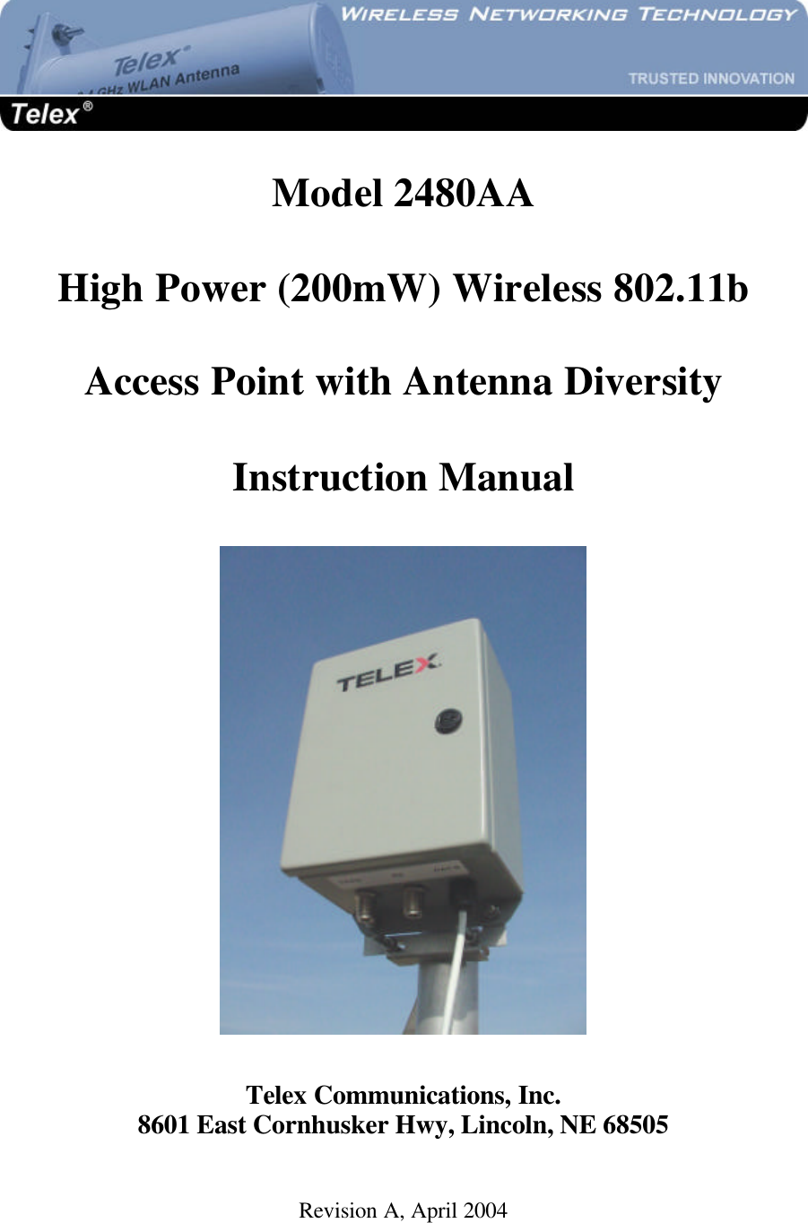
Bosch Security Systems AP200MW High Power Wireless 802.11b Access Point User Manual 2480AA Manual Rev A

Bosch Security Systems, Inc. High Power Wireless 802.11b Access Point 2480AA Manual Rev A

Manual revised

  Model 2480AA  High Power (200mW) Wireless 802.11b  Access Point with Antenna Diversity  Instruction Manual    Telex Communications, Inc. 8601 East Cornhusker Hwy, Lincoln, NE 68505  Revision A, April 2004
 2COPYRIGHT & TRADEMARKS Copyright @ 2004 Telex Communications, Inc., All Rights Reserved.  Microsoft, Windows, and the Windows logo are registered trademarks of Microsoft Corporation.  All other trademarks and brand names are the property of their respective proprietors. TELEX LIMITED WARRANTY Uniform Limited Warranty: Telex branded products are warranted by Telex Communications, Inc. against malfunction due to defects in materials and workmanship for a specified period, as noted in the individual product-line statements below, beginning with the date of  original purchase by the end-user. If such malfunction occurs during the specified period, the product will be repaired with new or remanufactured equivalent parts and products or replaced (at our option) without charge. The product will be returned to the customer prepaid.   Exclusions and Limitations: The Limited Warranty does not apply to: (a) exterior finish or appearance; (b) certain specific items described in the individual product-line statements below, (c) malfunction resulting from use or operation of the product other than as specified in the product data sheet or owner’s manual; (d) malfunction resulting from misuse or abuse of the product, including accidents; (e) defects resulting from excess moisture, lightning or power surges; or (f) malfunction occurring at any time after repairs have been made to the product by anyone other than a Telex Service Department or any of its authorized service representatives.  The Warranty is void if the label bearing the product serial number (if applicable) has been removed or defaced.  Other Express or Implied Warranties Excluded:  TO THE EXTENT PERMITTED BY APPLICABLE LAW, THE WARRANTIES SET FORTH HEREIN ARE IN LIEU OF, AND EXCLUSIVE OF, ALL OTHER WARRANTIES, EXPRESS OR IMPLIED.  SPECIFICALLY EXCLUDED, WITHOUT LIMITATION, ARE THE WARRANTIES OF MERCHANTABILITY, FITNESS FOR USE OR FOR A PARTICULAR PURPOSE, AND WARRANTIES ARISING FROM COURSE OF DEALING OR USAGE OF TRADE OR ANY OTHER MATTER.  IF, UNDER APPLICABLE LAW, IMPLIED WARRANTIES MAY NOT BE VALIDLY EXCLUDED, THE DURATION OF SUCH IMPLIED WARRANTIES IS LIMITED TO THE WARRANTY PERIOD.  Limitation of Remedies; Certain Damages Excluded:  REPAIR OR REPLACEMENT OF DEFECTIVE PRODUCTS ARE THE SOLE AND EXCLUSIVE REMEDIES PROVIDED BY TELEX TO THE CUSTOMER OR TO ANY OTHER PERSON AND SHALL CONSTITUTE FULL SATISFACTION OF ALL CLAIMS, WHETHER BASED ON CONTRACT, NEGLIGENCE, STRICT LIABILITY OR OTHERWISE.  TELEX’s MAXIMUM LIABILITY SHALL NOT EXCEED THE ACTUAL PURCHASE PRICE PAID FOR THE PRODUCT BY THE CUSTOMER.  TELEX AND ITS SUBSIDIARIES SHALL NOT BE LIABLE FOR ANY INDIRECT, INCIDENTAL, PUNITIVE, SPECIAL OR CONSEQUENTIAL DAMAGES INCLUDING, WITHOUT LIMITATION, INJURY TO PERSONS OR PROPERTY OR LOSS OF USE.  SOME STATES AND COUNTRIES DO NOT ALLOW THE EXCLUSION OR LIMITATION OF CERTAIN DAMAGES, SO THE ABOVE LIMITATION OR EXCLUSION MAY NOT APPLY TO YOU.  IN SUCH STATES AND COUNTRIES, TELEX SHALL BE LIABLE FOR NO MORE THAN THE DIRECT DAMAGES FOR BODILY INJURY AND/OR REAL OR PERSONAL PROPERTY ARISING FROM THE NEGLIGENCE OF TELEX.    Other Rights:  This warranty gives you specific legal rights, and you may also have other rights, depending upon where you live.  Obtaining Warranty Service: To obtain warranty service, a customer must deliver the product, prepaid, to the appropriate Telex Service Department listed below or any of its authorized service representatives together with proof of purchase of the product in the form of a bill of sale or invoice.   Applicable Law.  The validity, performance and construction of this Limited Warranty shall be governed by the laws of the State of Minnesota without reference to its choice of law principles.  The Minnesota federal courts and/or the state courts located in Hennepin County, Minnesota, shall have exclusive personal and subject matter jurisdiction over, and the parties shall each submit to the jurisdiction of such courts and to venue in Minnesota with respect to any dispute concerning the product or pursuant to this Limited Warranty, and all objections to such jurisdiction or to such venue are hereby waived.  For additional warranty repair or service information, contact the appropriate Telex service department listed below:    USA, Canada & Latin America       (DUPLICATION)    (WIRELESS, VEGA, WALS, LANDMOBILE) Telex Communications, Inc.   8601 E Cornhusker Way  West First Street    Lincoln, NE  68507 Blue Earth, MN 56013 USA   Tel:  402-467-5321 Tel: 507/526-3205    Fax: 402-467-3279 Fax: 507/526-3059  (EDUCATION AND AVIATION HEADSETS) 1720 E 14th Street       Glencoe, MN  55336 Tel:  320-864-3177 Fax:  320-864-3225  Germany, Rest of Europe and Africa & Middle East Mexico (Duplication)    (CB MICS) Telex EVI Audio GmbH.    Saguaro Elect Hirschberger Ring 45    Hermosillo, Mexico 83280 D 94315, Straubing, Germany   Tel:  011 5262 607012 Phone: +49 9421-706 0   Fax: 011 5262 607010 Fax: +49 9421-706 265
 3FCC STATEMENT This 802.11b Access Point has been tested and complies with the specifications for a Class B digital device, pursuant to Part 15 of the FCC Rules.  These limits are designed to provide reasonable protection against harmful interference in a residential installation.  This equipment generates, uses, and can radiate radio frequency energy and, if not installed and used according to the instructions, may cause harmful interference to radio communications.  However, there is no guarantee that interference will not occur in a particular installation.  If this equipment does cause harmful interference to radio or television reception, which is found by turning the equipment off and on, the user is encouraged to try to correct the interference by one or more of the following measures: • Reorient or relocate the receiving antenna • Increase the separation between the equipment or devices • Connect the equipment to an outlet other than the receiver’s • Consult a dealer or an experienced radio/TV technician for assistance  Changes or modifications not expressly approved by the manufacturer could void the user’s authority to operate the equipment! FCC Radiation Exposure Statement This equipment complies with FCC radiation exposure limits set forth for an uncontrolled environment.  This equipment should be installed and operated with minimum distance 20 cm (8 inches) between the radiator and your body. Installation Requirements The antenna used for this transmitter must not be co-located or operating in conjunction with any other antenna or transmitter.  This equipment must be professionally installed.  The professional installer is responsible for ensuring that the system is used exclusively for fixed, point-to-multipoint operations.  Any operation or installation not expressly approved by the manufacturer could void the user’s authority to operate the equipment.
 4Table of Contents  Warranty & Copyright Information    2 FCC Statement        3 Chapter 1: Introduction      6  The Telex 2480AA Access Point     6  Features        7  Package Contents       8  Chapter 2: Getting to Know the 2480AA AP   9  Inside the 2480AA AP      9  The Power-Over-Ethernet Injector          10  The 2480 AP LED’s       11  Chapter 3: Installing the 2480AA AP    12  Selecting a Mounting Location          12  Attaching to a Mast       13  Attaching to a Wall       13  Routing the CAT5 cable      13  Diversity Antennas       13  Chapter 4: Configuring the 2480AA AP    15  Change your computer network settings        16  Change the 2480AA AP settings          16  System Status        17  Configuration        18  Administration       23  Remote Access       24  Reset your computer network settings        24  Chapter 5: Managing the 2480AA AP    25  Chapter 6: Troubleshooting      26  Chapter 7: Firmware Documentation    27  Chapter 8: Specifications      28
 5Chapter 1: Introduction  The Telex 2480AA Access Point  Perfect for the campus, enterprise or wireless Internet service provider (WISP), the Telex 2480AA Access Point extends wireless connectivity to any 802.11b client device.  The 2480AA AP simply and efficiently transmits data between 10Base-T and your 2.4 GHz 802.11b clients.  The Telex 2480AA AP gives you the freedom to wirelessly connect any standard 802.11b networked client anywhere within it’s range.  A highly sensitive 200 mW radio and optional diversity reception means that you can easily cover distances of up to 12 miles in LOS or multipath environments.  Based on signal strength, it dynamically shifts between 11, 5.5, 2 and 1 Mbps network speeds for maximum reliability of connection.  So you’ve got the flexibility and performance you need from your wireless LAN or wireless ISP.    Wireless data or VoIP is transmitted and received from the client or CPE to the 2480AA Access Point on the 2.4 GHz ISM band.  The radio signal path should be line-of-sight (LOS) between the 2 antennas.  If the radio signal path is over a large body of water, such as a lake or bay, or if the signal passes through an urban area with several tall buildings, then multipath propagation may be present.  The 2480AA AP may be used with a single Tx/Rx antenna for normal LOS conditions, or a secondary Rx antenna may be used when multipath is present.
 6Features • Easy IE and Netscape Web browser configuration, no additional drivers needed • Interoperable with 802.11b (DSSS) 2.4 GHz Equipment, Prism 2.5 based • Up to 11 Mbps High-Speed Data Rate, Throughput up to 5 Mbps • High-Power (+23 dBm) and High Sensitivity (-95 dBm @ 1 Mbps) • 18VDC Power-over-Ethernet (PoE) supplied for distances up to 328 feet (100m) • Transient Suppression for high reliability • Broad operating temperature range, -21F to +125 F • AP visibility and beacon period selection • DTIM Interval (number of beacons per DTIM interval) • Multicast PM buffering • Maximum number of stations selection • Access Point name and SSID selection • Preamble Type selection (Long/Short/Both) • Channel selection (1-11 for US operation) • Basic, Supported and Transmission rate selection • Selectable static IP address or DHCP client mode • MAC address filtering • MAC address association list • Web server port selection • Adjustable RTS and fragmentation settings • 64 or 128 bit WEP with keys auto-generated from pass phrase • Ability to deny unencrypted data when WEP is enabled • Open or Shared key authentication when WEP is enabled • Support for firmware upgrades • FCC Certified with many Telex sector and omni antennas • Supports diversity antennas for reception • Standard mounting for flat walls or up to 2.5 inch OD masts • Waterproof cable entry • Type N antenna connectors • Rugged NEMA 4X enclosure
 7Package Contents           PoE Injector    18VDC power supply        Hardware pack                   CD & Quick Guide        2480AA AP  Tools and Hardware Needed:  The following tools will be needed to assemble and mount your 2480AA AP: 7/16” wrench Flat blade screwdriver for door latch 3/4” wrench or adjustable wrench for grommet nut UV-stable plastic cable ties or black electricians tape Wall or mast pipe on which to mount the AP Adequate length of exterior CAT-5 cable RJ45 plugs and crimping tool
 8Chapter 2: Getting to Know the 2480AA AP  Inside the 2480AA   AP  Before you can either test or install the Telex 2480AA AP, you must attach a length of CAT-5 Ethernet cable to the unit.  Open the door of the 2480AA AP using a standard flat blade screwdriver.  Insert one end of a length of CAT-5 8-conductor Ethernet cable through the hole marked CAT-5 and connect to the RJ-45 jack.     WARNING:  Before touching the PCB, make sure that you are grounded and have dissipated any static charge to ground.   You will see a small 2-position slide switch near the RJ45 socket.  If you are connecting the 2480AA AP directly to a computer network card or other Ethernet device, then slide this switch toward the RJ45 socket.  If you are connecting the 2480AA AP to a hub or switch, then slide this switch away from the RJ45 socket.  Later, when you apply power to the unit, the rightmost green LED will light, indicating an Ethernet connection has been made.
 9       There are two small pushbutton switches on the PCB.  The lower button is used if you wish to reset the 2480AA AP to factory default settings.  You should use this button if you forgot or lost the user name and/or password to the AP.  The reboot button only reboots the AP.  It does not change any settings.  If you are installing the 2480AA AP at this time, place the weatherproof grommet over the end of an unterminated length of outdoor-rated CAT-5 cable so that it will seat into the hole marked CAT-5.  Install the RJ-45 plug and test to make sure that all 8 conductors make contact.  Seat the weatherproof grommet into the hole on the bottom of the 2480AA enclosure and allow about 2” of cable to extend inside.  Place the locking nut over the RJ-45 plug and screw onto the end of the weatherproof grommet and tighten securely.  The CAT-5 cable should be free to slide within this grommet.  Plug the cable into the RJ-45 jack, then tighten the grommet to prevent the cable from moving.    The Power-over-Ethernet (PoE) injector  The Telex Wireless CPE uses a PoE injector to supply DC power to the device. To test or configure the 2480AA AP, install another RJ45 plug to the other end of your exterior CAT-5 cable and connect this end to the PoE box in the socket marked ANTENNA.  Also connect one end of the supplied 7 foot CAT5 patch cable in the socket marked COMPUTER.  The other end of this 7 foot cable will plug into the Ethernet port of your computer or into a hub or switch port.  Plug the supplied 18 volt 1 amp supply into a standard 110VAC outlet or power strip.  Plug the other end of this DC supply into the PoE box in the socket marked DC.  Crossover Switch RJ45 Jack Reset to Factory Default Reboot CAT-5 cable to PoE Power LED Ethernet Connection LED
 10WARNING:  Make sure that the antenna is pointed away from any humans or animals while power is applied!  A safe distance is approximately 7 inches or more.  The PoE injector box may be placed on the floor or mounted anywhere near the computer, hub, switch or router.         The 2480AA AP LED’s (v 1.0.2 firmware)  There are 4 LED’s visible from the inside of the 2480AA AP.  These can be seen when the door is opened. When powered-up, the first green LED on the right side will be lit ONLY if the PoE box is connected to an active Ethernet port.  If it does not light, then check that all cables are plugged into the PoE box and the power strip is turned on (if used).  If power is supplied and the cable is plugged into an active Ethernet card, hub, switch or router and the first green LED is not lit, then move the switch on the PCB inside the CPE to the other position.  If this LED is still not lit, then check the wiring of the RJ45 plugs on the CAT-5 cable.  Also check to make sure that the computer, hub, switch or router is turned on.  This green LED will fast blink when passing Ethernet traffic.  The second green LED will light steady when power is supplied to the unit.    Connect to 2480 AP Connect to hub, switch, router or computer Connect DC power cable here
 11Chapter 3: Installing the 2480AA AP  Selecting a Mounting Location  It is very important to position the 2480AA AP and it’s antenna(s) to ensure the highest possible data transfer speed in all kinds of weather and in all seasons.  The 2480AA AP operates on a radio frequency of 2.4 GHz and must be line-of-sight (LOS) with it’s clients.  Hills, buildings, trees and large vehicles must not block the signal path.  Trees are especially troublesome as they may allow the signal to pass easily in winter when leaves are off, but may block the signal in the other seasons. Check the FAQ’s under “Pre-Installation and Site Preparation” or  “Radio Propagation” or “Troubleshooting” on the Telex Wireless web pages for helpful hints.  (http://www.telex.com/Wireless/faq.nsf/c) Choose a location on the roof, tower, mast or wall for your 2480AA AP and antenna(s) so that it has a clear shot to your client base.  The closest client may not necessarily have the best path if it is blocked by hills, buildings or trees. Ensure that the signal path to each client has sufficient Fresnel zone clearance with respect to the ground or other obstacles near the path.  Check the Telex FAQ’s under “Radio Propagation” for more information on Fresnel zone clearance. Ensure that your mounting location is less than 100 meters from the computer, hub, switch or router location.  (Maximum length of CAT-5 cable is 100 meters)  Determine the building entry point ahead of time to prevent problems later. Attaching to a Mast First, attach the top U-bolt and U-bracket set to the mast with the tabs on the U-bracket pointing down.  Attach the 2480AA AP to these tabs, then install the lower set of U-bolt and U-bracket with the tabs up.  Attach the bottom U-bracket to the 2480AA AP.  Position the brackets in the desired location on the mast, then tighten all hardware.
 12Attaching to a Wall If attaching the 2480AA AP to a roof or wall, use appropriate hardware through the 4 holes provided in the 2480AA AP enclosure.  The U-bolts and U-brackets do not have to be used.   Routing the CAT-5 cable When you have completed installing and securing the 2480AA AP to it’s mount, attach and secure the CAT-5 cable to the mounting pipe or other support using tie wraps or black electrical tape.  Secure the CAT-5 cable to the outside wall of the building or tower leg using cable clamps or wood screws or other suitable hardware.  You will need to place a CAT-5 Surge Arrestor in series with the cable before it enters a building.  Also, create a “drip loop” before the cable enters through the wall of the building.  This prevents water from following the cable into the building. Pull any excess cable into the building, then weather-seal the hole around the CAT-5 cable with quality exterior grade sealant.  Route the cable to the PoE location inside the building.    Diversity Antennas  The Telex 2480AA AP is supplied with 2 Type N RF connectors for diversity reception.  Diversity is extremely helpful in maintaining wireless connections in the presence of multipath propagation.  Multipath is normally found near lakes, bays and other large bodies of water.  It is also found in urban environments where there are tall buildings to cause reflections.
 13The primary Tx/Rx antenna is connected to one port, and may be used by itself in a non-diversity installation.  The secondary Rx-only antenna is connected to the remaining port when diversity is used.  Both the primary and secondary antennas should be the same type and gain, and should be pointing in the same direction.  Shown below is a typical diagram for diversity antennas with vertical separation.  The primary and secondary antennas can be separated by as little as 5 feet or as much as 30 feet in either a vertical or horizontal plane.  See Chapter 8: 2480AA Specifications, for a complete list of FCC Certified antennas for the Telex 2480AA AP.
 14Chapter 4: Configuring the 2480AA AP  Overview  The Telex 2480AA AP is shipped with default (factory-set) values for certain network settings.  You will need to change these settings at the  Access Point location to match those of your ISP or IS Department.  To do this requires 3 main steps:  1.  Change your computer network settings to match the default network settings in the 2480AA AP so your computer can communicate with the AP configuration software.  2.  Using a standard web browser (Internet Explorer 5.5 or later, Netscape 7.0 or later), change the 2480AA AP wireless network settings from the default values to the values of your ISP or IS Dept.  3.  If necessary, change the network settings on the AP and computer to match other devices on a wired network connected to the computer.  If you do not know how to enable and change network setting on your PC, contact your network service provider (ISP or IS Dept.) support desk or a qualified PC technician for assistance.  If your network service provider has not already provided you with specific network settings to use, contact them now and ask for the following:  1.  The IP Address assigned to your AP: 2.  The corresponding Subnet Mask: 3.  The corresponding Default Gateway: 4.  The SSID, AP name, transmission rate and radio channel:  We recommend using static IP addresses for all AP’s.  However, if your network uses DHCP to assign IP addresses automatically to the AP, you will not need the IP address, Subnet Mask or Default Gateway.  Select the DHCP option from the 2480AA AP IP Address Mode on the IP Network screen to allow the AP to obtain an IP address automatically.   The AP name is used with the Telex Locator software for use in upgrading firmware.
 15 Step 1:  Change your computer network settings  a. Enable TCP/IP networking on your PC if you have not already done so, then right-click (use the right mouse button) on the Network (My Network Places) icon on your computer’s desktop and select Properties from the pop-up menu.  b.  Right-click on Local Area Connections and select Properties from the pop-up menu.  c. Click on the installed TCP/IP protocol, then click Properties.  d. Enter the following settings:  IP Address:   192.168.1.100     Subnet Mask:  255.255.255.0     Default Gateway:  192.168.1.1  e. Click OK to accept the settings.  f.  The NIC must be set to 10 Mbps and “Proxy Server” must be unchecked under LAN settings. You may add the IP address of this AP into the exceptions instead of disabling the proxy.  Restart your computer if prompted.  Step 2:  Change the 2480AA AP settings  Open your web browser.  (Internet Explorer 5.5 and 6.0 or Netscape 7.0 have been tested to work properly.  Other browsers may work but have not been verified.)  Open the following URL:  192.168.1.90  (select “try again” if the computer detects that you are offline.)  The following window should appear:    The first time that you use this, just press OK.  The User Name and Password will be set later.
 16System Status  The following Summary page should be displayed first. Make sure that the Firmware Version is current (see Chapter 7).  Check the Telex website occasionally to check for updates.  The IP Address shown is the same as that used to access this configuration software.  The MAC address is that of the radio card in this 2480 Access Point.     Select the Associations page to show associated client MAC addresses.  The clients must be actively passing data packets to this AP in order to show on this list. To refresh the list to include all associated clients, you may reboot the AP without changing any settings.
 17Configuration    To enter the Access Point Name, IP Address Mode, Default IP Address, Default Subnet Mask and Default gateway, select the IP Network screen as shown below.    Each AP on your network should have a unique Access Point Name.  This name is used when upgrading firmware with the Telex Locator Tool.    We recommend using static IP addresses for all AP’s.  However, if your network uses DHCP to assign IP addresses automatically to the AP, you will not need the IP address, Subnet Mask or Default Gateway.  Select the DHCP option from the 2480AA AP IP Address Mode on the IP Network screen to allow the AP to obtain an IP address automatically.  Make any changes you require, then click Save.
 18To enter the  SSID, Channel, Basic Rates, Supported Rates, Transmission Rate, or Preamble Type information, select the Wireless Network screen as shown below.    The Basic rates should be set depending on the speed of your network.  You must select 1 & 2 Mbps if you have older 802.11 compliant equipment that support only 1 or 2 Mbps.  Selecting 1 & 2 Mbps, however does NOT limit the basic transfer rates of faster adaptors.  These rates are only used for management frames, broadcast and multicast frames, not for data frames. The default setting enables all four rates.    The Supported Rates define the rates at which a wireless client will communicate with an AP.  When a station attempts to join the network, it checks the data rate used on the network.    The Transmission Rate is used to control the current transmit rate of a data packet.  This setting basically provides a means to set a fixed or auto rate value when the AP and a station are enabled to communicate at the current rate (defined by the supported rates).  Starting from the highest rate of the association, the fallback algorithm is triggered by the transmit failure of a frame (i.e. all retries have been sent without acknowledgement).  The fallback rate will last for an internally fixed time or until a number of successful transmissions controls the upgrade back to the highest rate.  Make any changes you require, then click Save.
 19To enter the Max Number of Stations, Fragmentation Threshold, RTS Threshold, Beacon Period, DTIM Interval and to enable Multicast PM buffering, select the Advanced Wireless screen.    If you have several AP’s at one location, set the Max Number of Stations to a lower value to balance the load on each AP.  We suggest using a value between 25 and 50 stations for most WISP installations.  This can be increased if client bandwidth limiting is used.  Telex recommends using the default value of Fragmentation Threshold and RTS Threshold for the 2480AA AP.  Only minor modifications of these 2 values are recommended.  The Beacon Period determines the interval of time between successive beacons.  The beacon is a packet broadcast by the AP to keep the network synchronized.  The DTIM Interval determines the number of beacons between each Delivery Traffic Indication Message (DTIM).  This informs clients of the next window for listening to broadcast and multicast messages.  When the AP has buffered broadcast or multicast messages for associated clients, it sends the next DTIM with a DTIM Interval value.  Clients for that AP hear the beacons and awaken to receive the broadcast and multicast messages.  Enabling Multicast PM buffering can avoid network congestion when there are too many clients to transmit data simultaneously.  Make any changes you require, then click Save.
 20To use standard WEP security, select the Wireless Security screen shown below and select WEP enabled.  Choose from either 64 or 128 bit WEP Key Length, then enter the pass phrase.  It is recommended to use a pass phrase that consists of 10 or more characters.  Make sure that your clients use the same WEP pass phrase or hex keys.  Select the WEP key to use for transmitting data from the AP to the clients.  For increased security, select Invisible from the Visibility Status and change the keys periodically.  If Invisible is selected, all clients will have to manually enter the correct SSID in their configuration.  When WEP is enabled, you should also enable Deny Unencrypted Data and select either Open or Shared or Both Shared Key Authentication.  Make any changes you require, then click Save.
 21For additional security, enable MAC address filtering from the MAC Filters screen.  You must manually enter each client’s MAC address.    HINT: When first setting up an AP with many clients, you can reboot the AP to force all associated clients to show up in the Association list, then copy & paste these MAC addresses into the MAC filter fields, then enable MAC filtering.    Make any changes you require, then click Save.
 22Administration  In the Admin Settings (Security) page shown below, you may set the User Name and Password for this web interface.  Make sure that you write down this information and store in a safe place so that it is not forgotten or stolen.  Any time that you wish to reset the AP to factory defaults, click on the Reset Configuration button on the Reboot & Reset page. The Admin Settings page also allows you to either Allow Upgrade Uploads or Not Allow.  For normal operation, leave this off.  The Web Server Port may also be changed if required.   User Name:  ______________________ Password:  ________________________  In the Reboot & Reset page shown below, you may use the Reboot button to immediately reboot the AP.  The Reset Configuration button will reset all configuration options to their factory default values.
 23 Remote Access  When all changes have been made and saved on the AP, close the browser. Subsequent changes may now be made from either the AP location or anywhere on the network as long as you are in the same subnet.    Step 3:  Reset Your Computer Network Settings  The last step in the AP configuration is to reset your computer network settings so they match the settings used by your Network.  This step may be skipped if no changes were made to the AP’s IP address during Step 2.  a. Right-click on the Network icon (My Network Places) on your computer’s desktop and select Properties from the pop-up menu.  b.  Right-click on “Local Area Connection” and select Properties from the pop-up menu.  c. Select the installed TCP/IP protocol, then click the Properties button.  d.  If using static IP addresses: Enter an IP Address for your computer that is different than the AP’s IP address.  Usually, you can use an IP number that is one higher than the AP IP address.  For example, if the AP’s IP address is 192.168.1.90 then assign 192.168.1.91 to the computer.  If you have many computers and AP’s in your network, then make sure that each uses a different IP address within the same subnet.  e. If using static IP addresses: Change your computer’s Subnet Mask and Default Gateway settings to match the values you received from your ISP or IS Dept.  f. If you selected “Obtain an IP address automatically” in your computer, then you will usually not be able to change the AP configuration settings until you reset the computer to a static IP.  Set the DNS Server information if necessary.  g. Click on OK in each window to accept the changes.  h. Restart your computer if prompted.
 24Chapter 5: Managing the 2480AA AP  The initial association of a CPE with the 2480AA AP must be performed at the client location.  However, once associated, both the AP and CPE settings may be monitored and changed from any computer on their same subnet.  For security reasons, it is best to keep the AP on a different subnet from the clients.  From any remote computer on the same subnet, open the web browser and enter the AP’s IP address as the URL.  You must know the User Name and Password for this AP in order to log in and change the settings.  Once logged-in to the AP from a wired or wireless backbone, you may change anything except the AP’s subnet.  If the backhaul link is lost, then you may only communicate with the AP after resetting the IP address.  After you have changed the AP’s configuration, press Save then Reboot.
 25Chapter 6: Troubleshooting  Problem: After plugging in all cables and applying DC power to PoE, no lights come on.  Possible Causes / Solutions: Cat-5 cable not wired to RJ45 plugs correctly.     -     Replace Cat-5 cable & check wiring Cables plugged into wrong jacks of PoE box     -     use correct jacks Defective power supply     -     Replace power supply Defective PCB in AP     -     Replace AP unit Defective PoE     -     Replace PoE box  Problem: Both Green lights are on and system tray shows connection to the NIC, but cannot load AP log-in page  Possible Causes / Solutions: Proxy Server box checked on LAN settings – uncheck this box Auto-negotiate function turned on in NIC – manually set to 10 Mbps  Problem: Second Green light (Power) is on but not first green light (Ethernet).  Possible Causes / Solutions: Straight/Cross-over switch in wrong position     -     move switch to other position Computer Network IP not set correctly     -     change Network IP to 192.168.1.100 Computer, hub, switch or router not turned on     -     turn on equipment Computer Cat-5 cable not plugged-in     -     plug cable in Cat-5 cable not wired correctly     -     Replace Cat-5 cable & check wiring  Problem: CPE MAC addresses initially show in Association list, but disappear later  Possible Causes / Solutions: No problem.  The MAC addresses will drop from the Association list when the CPE enters the sleep mode (no activity).  Check the AP FAQ’s on the Telex Wireless web pages for helpful hints and troubleshooting guides.  (http://www.telex.com/Wireless/faq.nsf/c)
 26Chapter 7: Firmware Documentation  The current firmware is 1.0.2 - 1.1.1 – 1.3.8.  To upgrade firmware, ensure that the AP and attached computer are on the same subnet.  In the AP Administration settings, enable “Allow Upgrade Uploads” and SAVE. Run the Telex Locator software (available from our website or on the supplied CD).  Select the correct AP name to upgrade, then click the Upgrade button.  Choose the correct bin file, then press “Upgrade”.  Upgrading will not change any settings in the AP configuration.    1.0.2-1.1.1-1.3.8 Release Notes:  Default settings:   IP: 192.168.1.90   Access Point Name:  802.11b AP   SSID: 802.11b AP   Channel: 1   Basic Rates:  all   Supported Rates:  all   Transmission Rate: Automatic   Preamble:  Long   Max Number of Stations:  200   Fragmentation Threshold:  2346   RTS Threshold:  2347   Beacon Period:  100 ms   DTIM Interval:  1   Multicast PM buffering:  on   No WEP, no user name, no password   Visibility:  Invisible   Disallow firmware upgrades   MAC filtering:  off   Web Server Port:  80
 27Chapter 8:  2480AA Specifications  General: Model Number   2480AA Standard    IEEE 802.11b, 802.3 Regulatory Certifications    FCC Part 15 Mode     Point-to-Multipoint under Part 15.247 Channels    11 Channels (US, Canada) Frequency Band      2.400 – 2.483 GHz Radio Type    Direct Sequence Spread Spectrum (DSSS) Modulation    CCK (11, 5.5 Mbps), DQPSK (2 Mbps), DBPSK (1 Mbps) Radio Raw Data Rate   11, 5.5, 2 and 1 Mbps, Auto Fall-Back Maximum Outdoor Range    approximately 12 miles (19 km) Wireless Security   64/128 bit WEP, MAC filtering Antenna Connectors   2 each Type N jacks (diversity receive)  Electrical Specifications: Operating Voltage   from 9 to 24 VDC, 18VDC supplied Operating Current   200 mA standby,  650 mA max (UDP), 500 mA max (TCP) Radio conducted output power 23 dBm (200 mW) Max Antenna gain   14.5 dBi (with 15’ LMR-400) Max EIRP    36 dBm (4 watts) Radio Sensitivity   -89 dBm @ 11 Mbps, -91 dBm @ 5.5 Mbps      -93 dBm @ 2 Mbps, -95 dBm @ 1 Mbps  Environmental: Temperature Range   -40F to 140 F (storage), -21F to 125 F (operating) Humidity    5% to 95% typical  Physical: AP Dimensions   8” x 6” x 4” AP Weight    4 lbs.  (1.8 kg) Wind Surface Area   0.33 sq. ft. (0.03 sq. m)  FCC Certified Antennas: Telex Antenna Model: 2437  2439  2442  2444  2443  2445 Antenna Type: Omni Omni Sector Sector Sector Sector Beamwidth: (degrees)  360  360  60  90  120  90 Gain: (dBi)  7.5  9.5  14  14.5  12  12 Cable Length: (ft) (LMR-400) 3  3  15  15  3  3 EIRP (dBm)  30  33  36  36  35  35 Polarization Vertical Vertical Vertical Vertical Vertical Horizontal

Navigation menu