Bosch Security Systems B116 Wireless Microphone Transmitter User Manual FMR RE 2PrelimManual042803

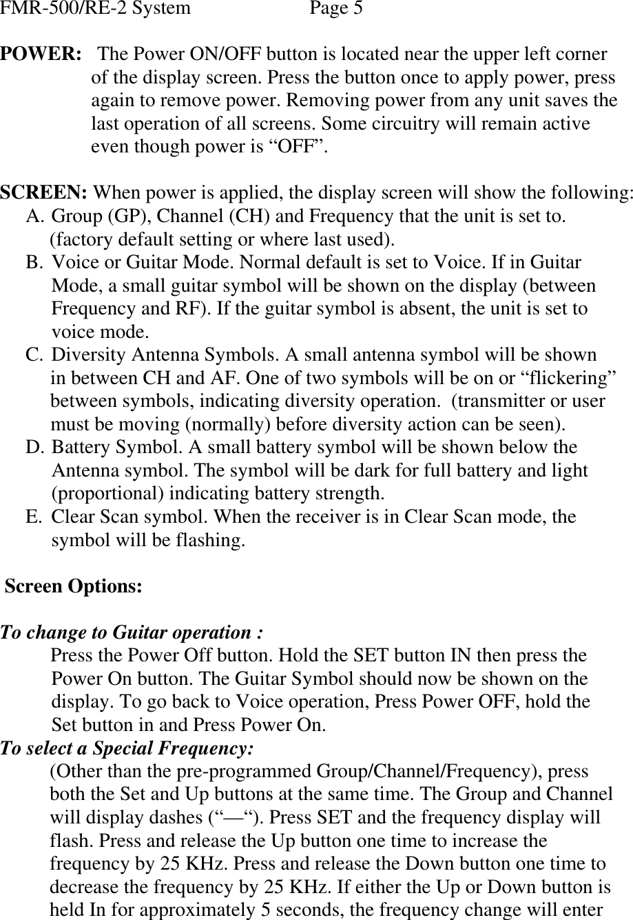
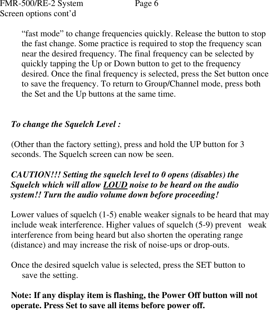
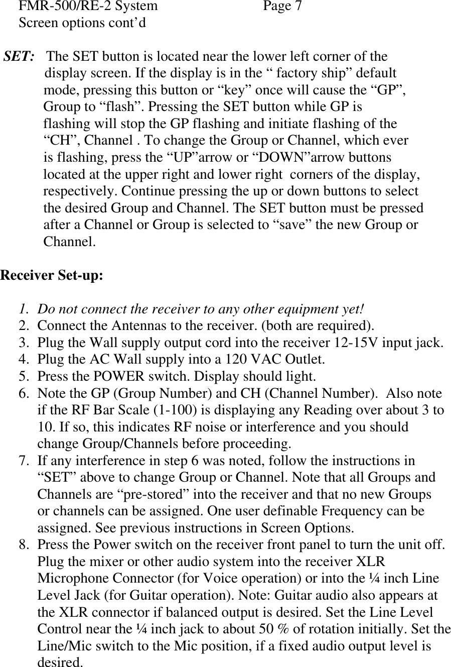
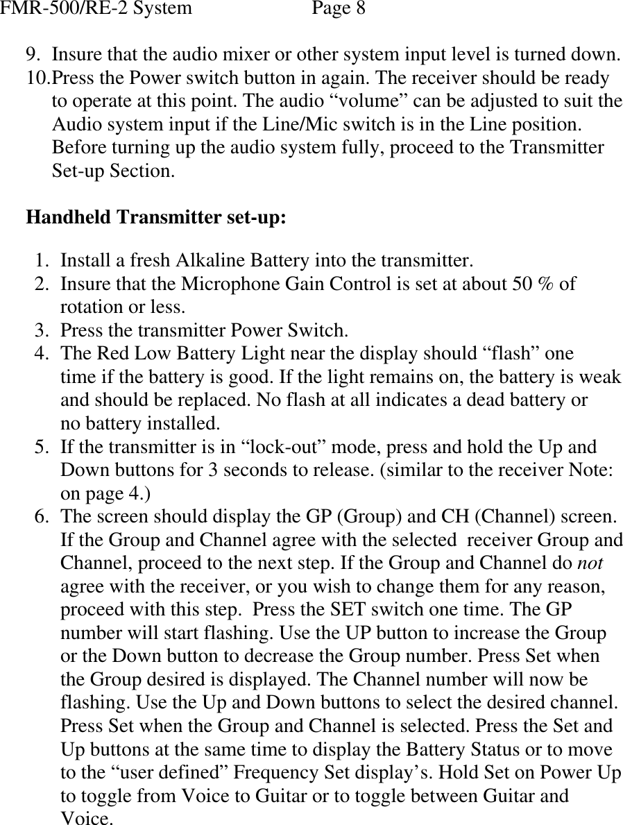
Bosch Security Systems, Inc. Wireless Microphone Transmitter FMR RE 2PrelimManual042803

users manual

Preliminary Users Manual, Telex FMR-500 System, Electro-Voice RE-2 System.  Telex Model FMR-500 Wireless Microphone Receiver, Electro-Voice RE-2 Receiver. Telex Model WT-500 Wireless Beltpack Transmitter, Electro-Voice BPU-2 Beltpack Transmitter. Telex Model HT-500 Wireless Handheld Transmitter, Electro-Voice HTU-2 Handheld Transmitter.  The components above form the Telex or Electro-Voice Wireless Microphone System. Each system is designed to be used in Live Sound Reinforcement applications where Sound Quality and Reliability are of prime importance. Simplicity of operation is assured along with flexibility for varying venues. Operating features and cosmetics are slightly different Between Telex and Electro-Voice (Ev) models but are electrically identical.  Features:  Receiver…. • Phase Locked Frequencies for stable Operation. • 950 Radio Channels, user programmable or factory installed. • LCD Display for ease of viewing. • Adjustable Line Level ¼ inch output jack. • Fixed Microphone Level XLR output jack. • Adjustable Microphone to Line Level XLR output level. • Front Panel Power ON/OFF Switch. • Input RF Filters cover 24 MHz Bandwidth (4 TV Channels). • SAW Filter 1st I.F for out of band rejection. • Triple ceramic filters in 2nd I.F for adjacent channel rejection. • Front panel Voice/Guitar selection. • Auto-selects voice/Guitar audio frequency characteristics. • Permanent Memory for frequency/system storage. • Front Panel Software Control of Squelch settings and channel monitor. • Double Squelch. Amplitude and Tone Squelch system prevents false squelch opening.  • Auto-Select “Clear-Scan” of frequencies speeds set-up time.Telex
FMR-500/RE-2 System                  Page 2  Handheld Transmitter……  • 950 Radio Channels, user programmable or factory installed. • Phase Locked Frequencies for Stable Operation. • Efficient current drain vs. power system. • Patented Internal Dipole antenna eliminates wires or “rubber duck” antennas. • Specially shaped Handle with “softpaint” for comfort and low handling noise. • 9 Volt Alkaline “rattle-proof” battery area. • Low Profile Audio Mute and Power Switch. • LCD Display for ease of viewing. • On-board frequency program and menu switch. • Permanent Memory for frequency/system storage. • Transmit Tone for squelch control. • Microphone Gain control for talent set-up. • Low Battery Gauge.  Beltpack Transmitter…..  • 950 Radio Channels, user programmable or factory installed. • Phase Locked Frequencies for Stable Operation. • Efficient current drain vs. power system. • Flexible wire rope replaceable antenna. • Microphone/Instrument input connector for personal selection of microphones/instruments. • Small Case Footprint for ease of wear. • Non detachable battery door with dual latches. • 9 Volt Alkaline battery operation. • Low Profile Power Switch.   • LCD Display for ease of viewing. • On-board frequency program and menu switch. • Permanent “Memory” for frequency/system storage. • Transmit Tone for squelch control. • Microphone Gain control for talent set-up. •  Low Battery Gauge.
FMR-500/RE-2 System      Page 3  General System Specifications:  Operating Frequency Range……………..614-746 MHz,      in 24 MHz wide bands. Frequency Stability……………………… 50 PPM. (18 PPM Euro). Channels…………………………………950 (25 KHz steps). RF Power Output…………………………30 mW  conducted, 0.18W ERP. Modulation Type…………………………FM, 40 KHz Deviation. Audio Frequency Range………………….50-15000 Hz, +/- 2 db.      (50-15000 Hz instruments) (100-15000 Hz microphones).      (actual frequency response depends on capsules/instrument). Audio Frequency Distortion………………0.5 % THD @ 1000 Hz typical. Audio Frequency Dynamic Range………..100 db. Audio Frequency Signal/Noise Ratio……..100 db. Temperature Range………………………..-18 deg.C to 54 deg. C.  Receiver: Sensitivity………………………………..1.0 uV for 12 db SINAD typical. Image Rejection………………………….60 db typical. Spurious Rejection……………………….60 db typical. Selectivity………………………………..230 KHz at –6 db points. Modulation Acceptance…………………..40 KHz nominal deviation. Squelch Type……………………………..Tone with Amplitude Backup. Squelch Adjustment Range……………….0 to 100 uV typical. Squelch Quieting………………………….100 db typical. Audio Output, Fixed mic level……………300 mV RMS/100K load typical.  (XLR Connector, balanced output) Audio Output, line level…………………..775 mV RMS/100K load typical.  (Quarter Inch Connector, unbalanced output) Audio Output, Adjustable, 10mV to 1.55 V RMS/100K load typical.  (XLR Connector, balanced output) Audio Signal to Noise ratio………………..94 db A Weighted. Audio Distortion (system)…………………0.5 % THD typical. Audio Frequency Response, instruments…..50-15000 Hz, +/- 2 db (system). Audio Frequency Response, microphones…100-15000 Hz, +/- 2 db (system).  (actual voice response depends on the microphone/instrument.)
FMR-500/RE-2 System   Page 4  Beltpack Transmitter.  RF Power Output………………………….. 30 mW typical, Terminated. Antenna……………………………………..1/4 Wave flexible. Modulation, FM………………………………….40 KHz Deviation. Modulation Limiter…………………………Limiter/Compressor. Audio Input…………………………………7.75 mV for 40 KHz Deviation.     (77.5 mV for instruments). Power………………………………………..9.0 VDC (Alkaline).  Handheld Transmitter.  RF Power Output………………………….. 30 mW typical, Terminated. Antenna……………………………………..Internal ½ Wave Dipole. Modulation, FM………………………………….40 KHz Deviation. Modulation Limiter…………………………Limiter/Compressor. Audio Input…………………………………395 mV for 40 KHz Deviation. Power………………………………………..9.0 VDC (Alkaline).        SYSTEM PROGRAMMING/OPERATION  The FMR-500/RE-2 System uses the same basic programming steps in the Receiver and Transmitters. Learning these basic steps early will save time and effort. Read the following section then proceed to the Set-Up Section.  Receiver:  Note: The FMR-500/RE-2 receiver is supplied with a “Secure” or lockout function. All of the “buttons” can be secured to prevent accidental operation or tampering. If the Set switch is pressed in Secure Mode, “Loc-Out” will appear on the screen. If the Up or Dow buttons are pressed in Secure Mode, nothing happens. Pressing the power button in Secure Mode will not turn the receiver off. To unlock the buttons, Press and Hold the Up and Down buttons for 3 seconds. ACC.ESS will appear as long as the buttons are held. To re-lock the receiver, press the Up and Down buttons for 3 seconds until Sec.uRE is displayed.
FMR-500/RE-2 System   Page 5  POWER:   The Power ON/OFF button is located near the upper left corner         of the display screen. Press the button once to apply power, press            again to remove power. Removing power from any unit saves the                 last operation of all screens. Some circuitry will remain active           even though power is “OFF”.   SCREEN: When power is applied, the display screen will show the following: A. Group (GP), Channel (CH) and Frequency that the unit is set to.           (factory default setting or where last used).  B. Voice or Guitar Mode. Normal default is set to Voice. If in Guitar Mode, a small guitar symbol will be shown on the display (between Frequency and RF). If the guitar symbol is absent, the unit is set to voice mode. C. Diversity Antenna Symbols. A small antenna symbol will be shown      in between CH and AF. One of two symbols will be on or “flickering”        between symbols, indicating diversity operation.  (transmitter or user       must be moving (normally) before diversity action can be seen). D. Battery Symbol. A small battery symbol will be shown below the  Antenna symbol. The symbol will be dark for full battery and light (proportional) indicating battery strength. E. Clear Scan symbol. When the receiver is in Clear Scan mode, the symbol will be flashing.   Screen Options:   To change to Guitar operation :      Press the Power Off button. Hold the SET button IN then press the    Power On button. The Guitar Symbol should now be shown on the  display. To go back to Voice operation, Press Power OFF, hold the Set button in and Press Power On.  To select a Special Frequency:            (Other than the pre-programmed Group/Channel/Frequency), press              both the Set and Up buttons at the same time. The Group and Channel             will display dashes (“—“). Press SET and the frequency display will            flash. Press and release the Up button one time to increase the            frequency by 25 KHz. Press and release the Down button one time to            decrease the frequency by 25 KHz. If either the Up or Down button is             held In for approximately 5 seconds, the frequency change will enter
FMR-500/RE-2 System   Page 6 Screen options cont’d            “fast mode” to change frequencies quickly. Release the button to stop            the fast change. Some practice is required to stop the frequency scan            near the desired frequency. The final frequency can be selected by           quickly tapping the Up or Down button to get to the frequency             desired. Once the final frequency is selected, press the Set button once            to save the frequency. To return to Group/Channel mode, press both             the Set and the Up buttons at the same time.   To change the Squelch Level :  (Other than the factory setting), press and hold the UP button for 3 seconds. The Squelch screen can now be seen.   CAUTION!!! Setting the squelch level to 0 opens (disables) the      Squelch which will allow LOUD noise to be heard on the audio       system!! Turn the audio volume down before proceeding!       Lower values of squelch (1-5) enable weaker signals to be heard that may include weak interference. Higher values of squelch (5-9) prevent   weak interference from being heard but also shorten the operating range (distance) and may increase the risk of noise-ups or drop-outs.  Once the desired squelch value is selected, press the SET button to       save the setting.   Note: If any display item is flashing, the Power Off button will not operate. Press Set to save all items before power off.
FMR-500/RE-2 System   Page 7 Screen options cont’d   SET:   The SET button is located near the lower left corner of the    display screen. If the display is in the “ factory ship” default              mode, pressing this button or “key” once will cause the “GP”,             Group to “flash”. Pressing the SET button while GP is                       flashing will stop the GP flashing and initiate flashing of the              “CH”, Channel . To change the Group or Channel, which ever                                 is flashing, press the “UP”arrow or “DOWN”arrow buttons              located at the upper right and lower right  corners of the display,              respectively. Continue pressing the up or down buttons to select              the desired Group and Channel. The SET button must be pressed               after a Channel or Group is selected to “save” the new Group or              Channel.    Receiver Set-up:  1. Do not connect the receiver to any other equipment yet! 2. Connect the Antennas to the receiver. (both are required). 3. Plug the Wall supply output cord into the receiver 12-15V input jack. 4. Plug the AC Wall supply into a 120 VAC Outlet. 5. Press the POWER switch. Display should light. 6. Note the GP (Group Number) and CH (Channel Number).  Also note if the RF Bar Scale (1-100) is displaying any Reading over about 3 to 10. If so, this indicates RF noise or interference and you should change Group/Channels before proceeding. 7. If any interference in step 6 was noted, follow the instructions in “SET” above to change Group or Channel. Note that all Groups and Channels are “pre-stored” into the receiver and that no new Groups or channels can be assigned. One user definable Frequency can be assigned. See previous instructions in Screen Options. 8. Press the Power switch on the receiver front panel to turn the unit off. Plug the mixer or other audio system into the receiver XLR Microphone Connector (for Voice operation) or into the ¼ inch Line Level Jack (for Guitar operation). Note: Guitar audio also appears at the XLR connector if balanced output is desired. Set the Line Level Control near the ¼ inch jack to about 50 % of rotation initially. Set the Line/Mic switch to the Mic position, if a fixed audio output level is desired.
FMR-500/RE-2 System   Page 8  9. Insure that the audio mixer or other system input level is turned down. 10. Press the Power switch button in again. The receiver should be ready to operate at this point. The audio “volume” can be adjusted to suit the Audio system input if the Line/Mic switch is in the Line position.  Before turning up the audio system fully, proceed to the Transmitter Set-up Section.   Handheld Transmitter set-up:  1. Install a fresh Alkaline Battery into the transmitter. 2. Insure that the Microphone Gain Control is set at about 50 % of rotation or less. 3. Press the transmitter Power Switch. 4. The Red Low Battery Light near the display should “flash” one time if the battery is good. If the light remains on, the battery is weak and should be replaced. No flash at all indicates a dead battery or no battery installed. 5. If the transmitter is in “lock-out” mode, press and hold the Up and   Down buttons for 3 seconds to release. (similar to the receiver Note: on page 4.) 6. The screen should display the GP (Group) and CH (Channel) screen. If the Group and Channel agree with the selected  receiver Group and Channel, proceed to the next step. If the Group and Channel do not agree with the receiver, or you wish to change them for any reason, proceed with this step.  Press the SET switch one time. The GP number will start flashing. Use the UP button to increase the Group or the Down button to decrease the Group number. Press Set when  the Group desired is displayed. The Channel number will now be flashing. Use the Up and Down buttons to select the desired channel. Press Set when the Group and Channel is selected. Press the Set and Up buttons at the same time to display the Battery Status or to move to the “user defined” Frequency Set display’s. Hold Set on Power Up to toggle from Voice to Guitar or to toggle between Guitar and Voice.
FMR-500/RE-2 System   Page 9  7. Monitor the FMR-500/RE-2 Receiver operating screen. Note that the RF (1-100) Bar graph should indicate near the 100 mark. The AF Bar should show very little If any indication until you talk or sing into the microphone. Adjust the microphone gain control if necessary to cause the AF Bar Graph to peak near –6 to –3 but not over +3 for best performance. 8. If you are satisfied with the Group/Channel and AF screen displays, the mixer or sound system gain/volume can be increased to monitor the sound. The Handheld System is now ready for use. 9. Press the Power button to turn the system off when complete.  Belt-Pack Transmitter set-up:  1.  Install a fresh Alkaline Battery into the transmitter. 2.  Insure that the Microphone Gain Control is set at about 50 % of        rotation or less. 3.  Press the transmitter Power Switch.    The Red Low Battery Light near the display should “flash” one           time if the battery is good. If the light remains on, the battery is weak            and should be replaced. No flash at all indicates a dead battery or           no battery installed. 4. The screen should display the GP (Group) and CH (Channel) screen. If the Group and Channel agree with the receiver Group and Channel, proceed to the next step. If the Group and Channel do not agree with the receiver, or you wish to change them for any reason, proceed with this step.  Press the SET switch one time. The GP number will start flashing. Use the UP button to increase the Group           or the Down button to decrease the Group number. Press Set when            the Group desired is displayed. The Channel number will now be             flashing. Use the Up and Down buttons to select the desired channel.           Press Set when the Group and Channel is selected.  5. Monitor the FMR-500/RE-2 Receiver operating screen. Note that the RF (1-100) Bar graph should indicate near the 100 mark. Place the microphone and cord in the position it will be used in.The AF Bar should show very little If any indication until you talk or sing into the microphone. Do not close talk the lapel microphone. Adjust the microphone gain control if necessary to cause the AF Bar Graph to peak near –6 to –3 but not over +3 for best performance.
FMR-500/RE-2 System   Page 10 Belt pack set-up cont’d.  6. If you are satisfied with the Group/Channel and AF screen displays, the mixer or sound system gain/volume can be increased to monitor the sound. The Beltpack System is ready for use. 7. Press the Power button to turn the unit off when complete.   END Preliminary Manual.

Navigation menu