Bosch Security Systems CPE50MW 2472AA Wireless CPE/Outdoor Bridge User Manual 2472AA Manual Rev A
Bosch Security Systems, Inc. 2472AA Wireless CPE/Outdoor Bridge 2472AA Manual Rev A
Manual revised
Model 2472AA
Long Range, Moderate Power
Wireless CPE/Outdoor Bridge
Instruction Manual
Telex Communications, Inc.
8601 East Cornhusker Hwy, Lincoln, NE 68505
Rev. A, April 2004
2
COPYRIGHT & TRADEMARKS
Copyright @ 2003 Telex Communications, Inc., All Rights Reserved. Microsoft,
Windows, and the Windows logo are registered trademarks of Microsoft
Corporation. All other trademarks and brand names are the property of their
respective proprietors.
TELEX LIMITED WARRANTY
Uniform Limited Warranty: Telex branded products are warranted by Telex Communications, Inc. against malfunction due to defects in materials and
workmanship for a specified period, as noted in the individual product-line statements below, beginning with the date of original purchase by the end-
user. If such malfunction occurs during the specified period, the product will be repaired with new or remanufactured equivalent parts and products or
replaced (at our option) without charge. The product will be returned to the customer prepaid.
Exclusions and Limitations: The Limited Warranty does not apply to: (a) exterior finish or appearance; (b) certain specific items described in the
individual product-line statements below, (c) malfunction resulting from use or operation of the product other than as specified in the product data sheet
or owner’s manual; (d) malfunction resulting from misuse or abuse of the product, including accidents; (e) defects resulting from excess moisture,
lightning or power surges; or (f) malfunction occurring at any time after repairs have been made to the product by anyone other than a Telex Service
Department or any of its authorized service representatives. The Warranty is void if the label bearing the product serial number (if applicable) has
been removed or def aced.
Other Express or Implied Warranties Excluded: TO THE EXTENT PERMITTED BY APPLICABLE LAW, THE WARRANTIES SET FORTH HEREIN
ARE IN LIEU OF, AND EXCLUSIVE OF, ALL OTHER WARRANTIES, EXPRESS OR IMPLIED. SPECIFICALLY EXCLUDED, WITHOUT
LIMITATION, ARE THE WARRANTIES OF MERCHANTABILITY, FITNESS FOR USE OR FOR A PARTICULAR PURPOSE, AND WARRANTIES
ARISING FROM COURSE OF DEALING OR USAGE OF TRADE OR ANY OTHER MATTER. IF, UNDER APPLICABLE LAW, IMPLIED
WARRANTIES MAY NOT BE VALIDLY EXCLUDED, THE DURATION OF SUCH IMPLIED WARRANTIES IS LIMITED TO THE WARRANTY
PERIOD.
Limitation of Remedies; Certain Damages Excluded: REPAIR OR REPLACEMENT OF DEFECTIVE PRODUCTS ARE THE SOLE AND
EXCLUSIVE REMEDIES PROVIDED BY TELEX TO THE CUSTOMER OR TO ANY OTHER PERSON AND SHALL CONSTITUTE FULL
SATISFACTION OF ALL CLAIMS, WHETHER BASED ON CONTRACT, NEGLIGENCE, STRICT LIABILITY OR OTHERWISE. TELEX’s MAXIMUM
LIABILITY SHALL NOT EXCEED THE ACTUAL PURCHASE PRICE PAID FOR THE PRODUCT BY THE CUSTOMER. TELEX AND ITS
SUBSIDIARIES SHALL NOT BE LIABLE FOR ANY INDIRECT, INCIDENTAL, PUNITIVE, SPECIAL OR CONSEQUENTIAL DAMAGES INCLUDING,
WITHOUT LIMITATION, INJURY TO PERSONS OR PROPERTY OR LOSS OF USE. SOME STATES AND COUNTRIES DO NOT ALLOW THE
EXCLUSION OR LIMITATION OF CERTAIN DAMAGES, SO THE ABOVE LIMITATION OR EXCLUSION MAY NOT APPLY TO YOU. IN SUCH
STATES AND COUNTRIES, TELEX SHALL BE LIABLE FOR NO MORE THAN THE DIRECT DAMAGES FOR BODILY INJURY AND/OR REAL OR
PERSONAL PROPERTY ARISING FROM THE NEGLIGENCE OF TELEX.
Other Rights: This warranty gives you specific legal rights, and you may also have other rights, depending upon where you live.
Obtaining Warranty Service: To obtain warranty service, a customer must deliver the product, prepaid, to the appropriate Telex Service Department
listed below or any of its authorized service representatives together with proof of purchase of the product in the form of a bill of sale or invoice.
Applicable Law. The validity, performance and construction of this Limited Warranty shall be governed by the laws of the State of Minnesota without
reference to its choice of law principles. The Minnesota federal courts and/or the state courts located in Hennepin County, Minnesota, shall have
exclusive personal and subject matter jurisdiction over, and the parties shall each submit to the jurisdiction of such courts and to venue in Minnesota
with respect to any dispute concerning the product or pursuant to this Limited Warranty, and all objections to such jurisdiction or to such venue are
hereby waived.
For additional warranty repair or service information, contact the appropriate Telex service department listed below:
USA, Canada & Latin America
(DUPLICATION) (WIRELESS, VEGA, WALS, LANDMOBILE)
Telex Communications, Inc. 8601 E Cornhusker Way
West First Street Lincoln, NE 68507
Blue Earth, MN 56013 USA Tel: 402-467-5321
Tel: 507/526-3205 Fax: 402-467-3279
Fax: 507/526-3059
(EDUCATION AND AVIATION HEADSETS)
1720 E 14th
Street
Glencoe, MN 55336
Tel: 320-864-3177
Fax: 320-864-3225
Germany, Rest of Europe and Africa & Middle East Mexico
(Duplication) (CB MICS)
Telex EVI Audio GmbH. Saguaro Elect
Hirschberger Ring 45 Hermosillo, Mexico 83280
D 94315, Straubing, Germany Tel: 011 5262 607012
Phone: +49 9421-706 0 Fax: 011 5262 607010
Fax: +49 9421-706 265
3
FCC STATEMENT
This Wireless CPE has been tested and complies with the specifications for a
Class B digital device, pursuant to Part 15 of the FCC Rules. These limits are
designed to provide reasonable protection against harmful interference in a
residential installation. This equipment generates, uses, and can radiate radio
frequency energy and, if not installed and used according to the instructions, may
cause harmful interference to radio communications. However, there is no
guarantee that interference will not occur in a particular installation. If this
equipment does cause harmful interference to radio or television reception, which
is found by turning the equipment off and on, the user is encouraged to try to
correct the interference by one or more of the following measures:
• Reorient or relocate the receiving antenna
• Increase the separation between the equipment or devices
• Connect the equipment to an outlet other than the receiver’s
• Consult a dealer or an experienced radio/TV technician for assistance
Changes or modifications not expressly approved by the manufacturer could
void the user’s authority to operate the equipment!
FCC Radiation Exposure Statement
This equipment complies with FCC radiation exposure limits set forth for an
uncontrolled environment. This equipment should be installed and operated with
minimum distance 20 cm (8 inches) between the radiator and your body.
Installation Requirements
The antenna used for this transmitter must not be co-located or operating in
conjunction with any other antenna or transmitter. The operator of this
transmitter, or if the equipment is professionally installed, the installer, is
responsible for ensuring that the system is used exclusively for fixed, point-to-
point operations.
4
Table of Contents
Warranty & Copyright Information 2
FCC Statement 3
Chapter 1: Introduction 6
The Telex Wireless CPE/Outdoor Bridge 6
Features 7
Package Contents 8
Chapter 2: Getting to Know the Wireless CPE 9
Inside the Wireless CPE 9
The Power-Over-Ethernet Injector 10
The Rear Panel LED’s 11
Chapter 3: Installing the Wireless CPE 12
Selecting a Mounting Location 12
Attaching the Mounting Bracket and Aiming 13
Routing the CAT5 cable 14
Connecting the Wireless CPE 14
Chapter 4: Configuring the Wireless CPE 16
Change your computer network settings 17
Change the CPE wireless settings 17
System Status 18
Configuration 20
Administration 22
Tools 23
Help 24
Reset your computer network settings 25
Chapter 5: Managing the Wireless CPE 26
Chapter 6: Troubleshooting 27
Chapter 7: Firmware Documentation 28
Chapter 8: Specifications 29
5
Chapter 1: Introduction
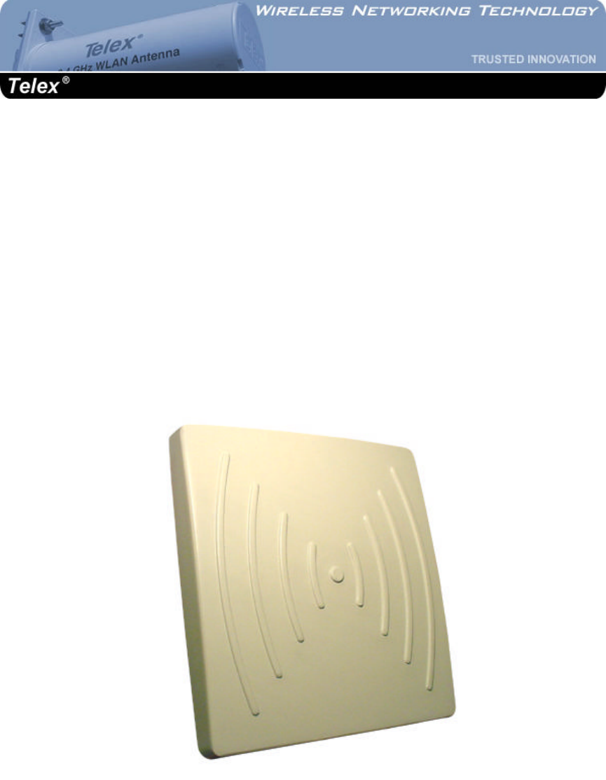
The Telex Wireless CPE/Outdoor Bridge
Perfect for the home or small office connection to the network, the Telex Wireless CPE
(Customer Premise Equipment) extends wireless connectivity from an access point to any
Ethernet-ready network device, such as a switch, router, desktop or notebook PC. The Wireless
CPE simply and efficiently transmits data between 10Base-T and your wireless LAN or wireless
ISP access point.
The Telex Wireless CPE gives you the freedom to place any standard networked computer
anywhere within range of an access point. A built-in 18 dBi antenna and 50 mW radio means
that you can easily cover distances of up to 8 miles at 1 Mbps and up to 3 miles at 11 Mbps.
Based on signal strength, it dynamically shifts between 11, 5.5, 2 and 1 Mbps network speeds for
maximum reliability of connection. So you’ve got the flexibility and performance you need
from your wireless LAN or wireless ISP.
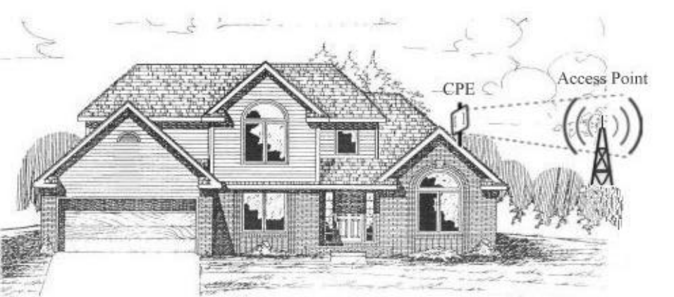
Wireless data or VoIP is transmitted and received from the CPE to the network access point (AP)
on the 2.4 GHz ISM band. The radio signal path must be line-of-sight (LOS) between the 2
antennas.
6
Features
• An All-in-One Wireless Solution for any Ethernet-Ready Network Device
• Easy IE and Netscape Web browser configuration, no additional drivers needed
• Interoperable with 802.11b (DSSS) 2.4 GHz Equipment, Prism 2.5 based
• Up to 11 Mbps High-Speed Data Rate, Throughput up to 5.5 Mbps
• Moderate-Power (+35 dBm EIRP) and Moderate Sensitivity (-89 dBm @ 1 Mbps)
• 12VDC Power-over-Ethernet (PoE) supplied, up to 24VDC available
• Transient Suppression for high reliability
• Broad operating temperature, -20 to +125 F
• All nearby 802.11b access point information displayed in Wireless Scan
• Clickable association with access point within Wireless Scan
• Manual entry of ad-hoc or infrastructure mode, SSID, channel, transmission rate and
access point density available
• Selectable static IP address or DHCP client mode
• Selectable MAC address cloning
• Selectable inbound and outbound bandwidth limiting from 64 Kbps to 1500 Kbps
• Signal and noise displayed in dBm, quality displayed in %
• Tx Rate, Link quality, signal strength and noise displayed in large font in new window
for antenna aiming
• Adjustable RTS and fragmentation settings
• Up to 128 bit WEP with keys auto-generated from pass phrase
• Ability to deny unencrypted data when WEP is enabled
• Shared key authentication available when WEP is enabled
• Layer 2.5 bridging
• Changeable settings for port interface access to web server
• Support for firmware upgrades
• Syslog client option for events logging
• Integrated 18 dBi antenna with 18 degree beam widths in both planes
• Standard multimount for DSS, mast & under eaves (fascia) mounting
• Selectable vertical or horizontal antenna polarization
• Waterproof cable entry
• Waterproof and dustproof radome enclosure
• Removable, serviceable radio area within CPE
• LED status lights visible through window on back panel
7
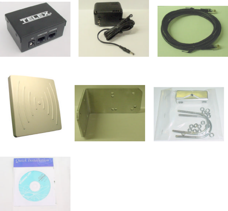
Package Contents
PoE Injector 12V Power Supply 7’ Cat5 Cable
Telex CPE Angle Bracket Hardware pack
CD & Quick Guide
Tools and Hardware Needed:
The following tools will be needed to assemble and mount your wireless CPE:
7/16” nut driver or wrench
5/16” nut driver or wrench
3/4” wrench or adjustable wrench for grommet nut
UV-stable plastic cable ties or black electricians tape
Mast pipe or DSS dish mount on which to mount the CPE
Adequate length of exterior CAT-5 cable
RJ45 plugs and crimping tool
8
Chapter 2: Getting to Know the Wireless CPE
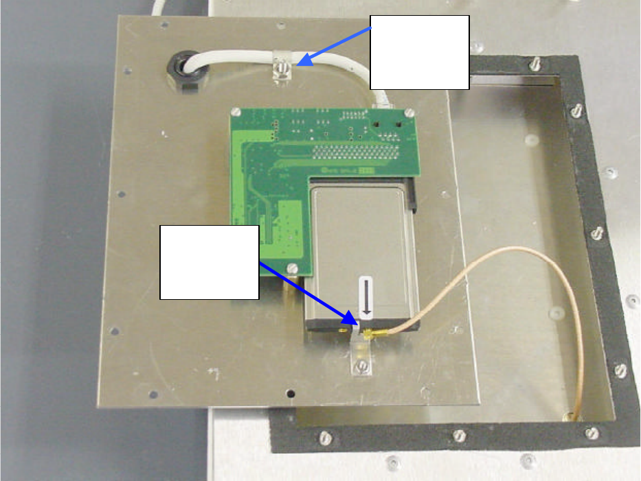
Inside the Wireless CPE
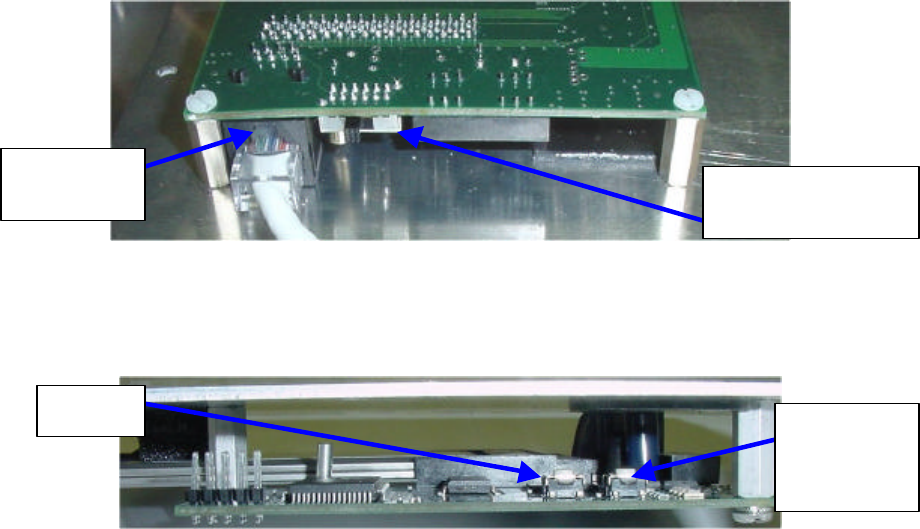
Before you can either test or install the Telex Wireless CPE, you must attach a length of outdoor-
rated (external) CAT-5 Ethernet cable to the unit. Remove the access panel from the rear panel
of the CPE using a 5/16” nut driver or wrench. Loosen the plastic nut on the outside of the
waterproof cable entry grommet, then insert the unterminated end of a length of exterior CAT-5
8-conductor Ethernet cable through this grommet.
Attach a standard RJ45 connector to the end of this cable using standard wiring for a straight
(non-crossover) connection. Plug this connector into the RJ45 socket on the PCB (printed circuit
board) that is attached to the access panel. Tighten down the cable strain relief clamp on the
cable. Do NOT unplug the small antenna cable from the radio card unless absolutely necessary.
WARNING: Before touching the PCB, make sure that you are grounded and have dissipated
any static charge to ground.
Antenna
Cable
connection
Cable
strain relief
clamp
9
You will see a small 2-position slide switch near the RJ45 socket. If you are connecting the
wireless CPE directly to a computer network card or other Ethernet device, then slide this switch
toward the RJ45 socket. If you are connecting the wireless CPE to a hub or switch, then slide
this switch away from the RJ45 socket. Later, when you apply power to the unit, the second
green LED will indicate if this switch position was properly selected.
There are two small pushbutton switches on the PCB. These are only used if you wish to reset
the wireless CPE to factory default settings. (e.g. you forgot or lost the user name and/or
password)
Allow approximately 6 inches of CAT-5 cable between the grommet and the PCB, then tighten
the outside nut of the weatherproof grommet. Also ensure that the inside nut is secure. Make
sure that both the small antenna cable and the CAT-5 cable are secure, then re-attach the access
panel to the CPE rear panel before proceeding.
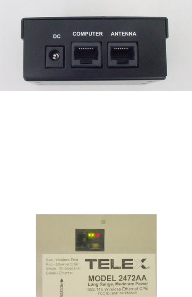
The Power-over-Ethernet (PoE) injector
The Telex Wireless CPE uses a PoE injector to supply DC power to the device. To test the
wireless CPE, install another RJ45 plug to the other end of your exterior CAT-5 cable and
connect this end to the PoE box in the socket marked ANTENNA. Also connect one end of the
supplied 7 foot CAT5 patch cable in the socket marked COMPUTER. The other end of this 7
foot cable will plug into the Ethernet port of your computer or into a hub or switch port. Plug the
supplied 12 volt 1 amp supply into a standard 110VAC outlet or power strip. Plug the other end
of this DC supply into the PoE box in the socket marked DC.
WARNING: Make sure that the antenna is pointed away from any humans or animals while
power is applied! A safe distance is approximately 10 inches or more.
The PoE injector box may be placed on the floor or mounted anywhere near the computer, hub,
switch or router.
Crossover
Switch
RJ45
Jack
Reset to
Factory
Default
Reboot
10
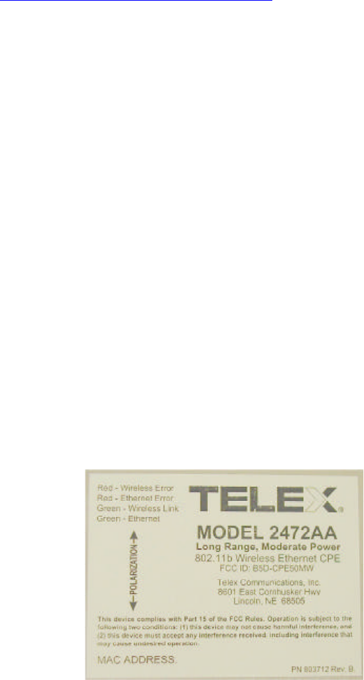
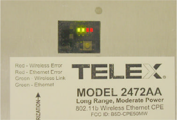
The Rear Panel LED’s (v 1.2.5 firmware)
There are 4 LED’s visible from the rear side of the wireless CPE. These can be seen through the
small window in the access panel. When powered-up, the first green LED will be lit ONLY if the
PoE box is connected to an active Ethernet port. If it does not light, then check that all cables are
plugged into the PoE box and the power strip is turned on (if used). If power is supplied and the
cable is plugged into an active Ethernet card, hub, switch or router and the first green LED is not
lit, then move the switch on the PCB inside the CPE to the other position. If this LED is still not
lit, then check the wiring of the RJ45 plugs on the exterior CAT-5 cable. Also check to make
sure that the computer, hub, switch or router is turned on. This green LED will fast blink when
passing Ethernet traffic. The second green LED will light when a connection or association has
been established to a wireless access point and will blink when passing wireless traffic.
The first red LED (3rd LED in line) indicates an Ethernet collision. The second red LED (4th
LED in line) indicates a WLAN error. This LED will light if an access point goes down or is
unavailable after a connection has been made with the CPE. This LED will NOT light if the
SSID is left blank (to use any SSID) and no access points are available. In general, the GREEN
LED’s indicate normal operating conditions and the RED LED’s indicate errors.
The window that covers these LED’s should be securely attached to the access panel at all times.
This helps to keep dust and moisture out of the CPE.
WARNING: Unplug the power supply from the PoE box before installing or handling the
wireless CPE.
11
Chapter 3: Installing the Wireless CPE
Selecting a Mounting Location
It is very important to position the CPE to ensure the highest possible data transfer speed in all
kinds of weather and in all seasons. The wireless CPE operates on a radio frequency of 2.4 GHz
and must be line-of-sight (LOS) with the access point (AP) or other CPE if in Ad-Hoc mode.
Hills, buildings, trees and large vehicles must not block the signal path. Trees are especially
troublesome as they may allow the signal to pass easily in winter when leaves are off, but may
block the signal in the other seasons. Check the FAQ’s under “Pre-Installation and Site
Preparation” or “Radio Propagation” or “Troubleshooting” on the Telex Wireless web pages for
helpful hints. (http://www.telex.com/Wireless/faq.nsf/c)
Determine the exact location of the nearest Access Points (AP’s) in your system. Choose a
location on the roof, mast, wall or fascia for your wireless CPE so that the CPE has a clear shot
to your AP. The closest AP may not necessarily have the best path if it is blocked by hills,
buildings or trees.
Ensure that the chosen signal path has sufficient Fresnel zone clearance with respect to the
ground or other obstacles near the path. Check the Telex FAQ’s under “Radio Propagation” for
more information on Fresnel zone clearance.
Ensure that your mounting location is less than 100 meters from the computer, hub, switch or
router location. (Maximum length of CAT-5 cable is 100 meters) Determine the building entry
point ahead of time to prevent problems later.
Limit the exposure of the CPE to wind if possible. Mounting the CPE on the fascia (under the
eaves) is best if the signal path is not blocked in this location.
Attaching the Mounting Bracket and Aiming
First, determine the polarization of the wireless CPE. If the Access Point uses vertical
polarization (V-pol), then the CPE must be installed vertically polarized. If the AP is H-pol, then
the CPE must be installed horizontally polarized. The arrow on the CPE label points vertically
when it is V-pol, and horizontally when H-pol. The arrow direction also corresponds with the
long dimension of the CPE radome.
12
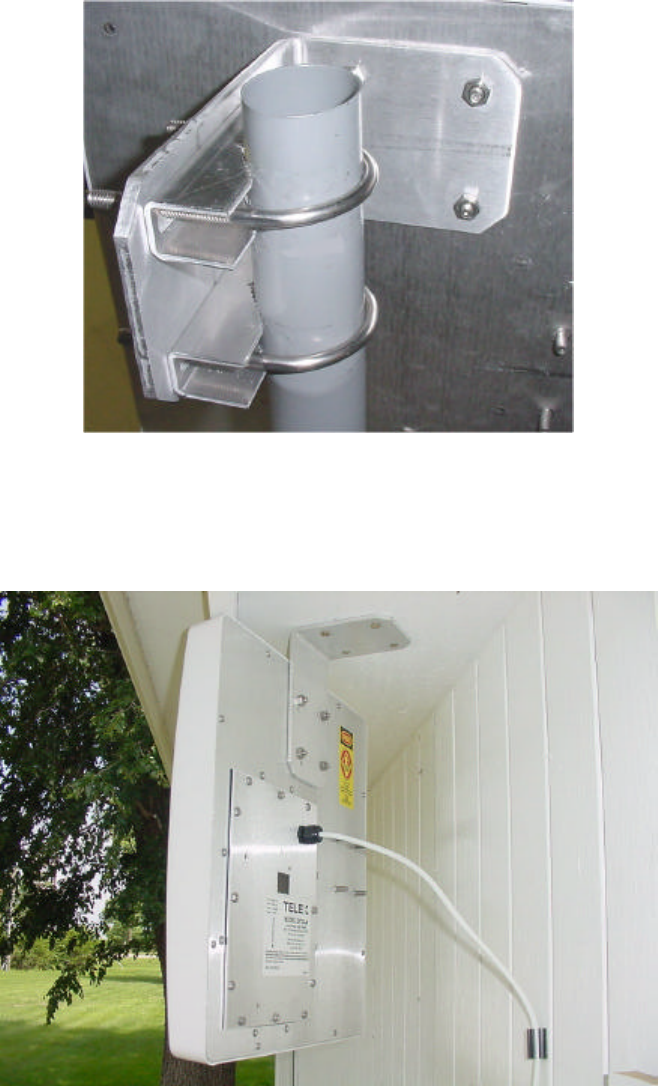
If attaching the wireless CPE to a mast, pipe or DSS dish-mount, then attach the angle bracket to
the mast as shown, using the U-bolts, nuts, washers and serrated clamps from the parts bag. If
possible, sight along the top of the angle bracket to aim the wireless CPE in the correct direction.
If you are using a vertical mast and require upward or downward beam tilt to the AP, then use
the optional holes in the angle bracket to obtain a 10 degree tilt, either up or down. If you
require more than 10 degrees, then use a standard DSS dish-mount instead. After aiming the
bracket, attach the CPE unit to the angle bracket using the remaining washers and nuts. Tighten
securely after checking the signal strength.
If attaching the wireless CPE to the fascia (under eaves), then secure the angle bracket to the
fascia with a single wood screw, attach the CPE to the bracket, aim for maximum signal and
finally secure the bracket with the 3 remaining wood screws. Make sure that the fascia is strong
enough to support the weight and wind load of the CPE!
13
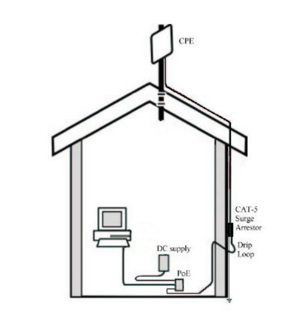
Routing the CAT-5 cable
When you have completed aiming and securing the CPE to the mount, attach and secure the
CAT-5 cable to the mounting pipe or other support using tie wraps or black electrical tape.
Secure the CAT-5 cable to the outside wall of the building using cable clamps and wood screws
or other suitable hardware. It is advisable to place a CAT-5 Surge Arrestor in series with the
cable before it enters the building. Also, create a “drip loop” before the cable enters through the
wall of the building. This prevents water from following the cable into the building.
Pull any excess cable into the building, then weather-seal the hole around the CAT-5 cable with
quality exterior grade sealant. Route the cable to the PoE location inside the building.
Connecting the Wireless CPE
Install an RJ45 plug to the end of your exterior CAT-5 cable and connect this end to the PoE box
in the socket marked ANTENNA. Also connect one end of the supplied 7 foot CAT-5 patch
cable in the socket marked COMPUTER. The other end of this 7 foot cable will plug into the
Ethernet port of your computer or into a hub or switch port. Plug the supplied 12 volt 1 amp
supply into a standard 110VAC outlet or power strip. Plug the other end of this DC supply into
the PoE box in the socket marked DC.
14
WARNING: Make sure that the front of the antenna is pointed away from any humans or
animals while power is applied! A safe distance is approximately 10 inches or more. The rear
side of the CPE is always safe.
The PoE injector box may be placed on the floor or mounted anywhere near the computer, hub,
switch or router.
There are 4 LED’s visible from the rear side of the wireless CPE. These can be seen through the
small window in the access panel. When powered-up, the first green LED will be lit ONLY if the
PoE box is connected to an active Ethernet port. If it does not light, then check that all cables are
plugged into the PoE box and the power strip is turned on (if used). If power is supplied and the
cable is plugged into an active Ethernet card, hub, switch or router and the first green LED is not
lit, then move the switch on the PCB inside the CPE to the other position. If this LED is still not
lit, then check the wiring of the RJ45 plugs on the exterior CAT-5 cable. Also check to make
sure that the computer, hub, switch or router is turned on. This green LED will fast blink when
passing Ethernet traffic. The second green LED will light when a connection or association has
been established to a wireless access point and will blink when passing wireless traffic.
The first red LED (3rd LED in line) indicates an Ethernet collision. The second red LED (4th
LED in line) indicates a WLAN error. This LED will light if an access point goes down or is
unavailable after a connection has been made with the CPE. This LED will NOT light if the
SSID is left blank (to use any SSID) and no access points are available. In general, the GREEN
LED’s indicate normal operating conditions and the RED LED’s indicate errors.
15
Chapter 4: Configuring the Wireless CPE
Overview
The Telex wireless CPE is shipped with default (factory-set) values for certain network settings.
You will need to change these settings at the client location to match those provided by your ISP
or IS Department.
To do this requires 3 main steps:
1. Change your computer network settings to match the default network settings in the CPE so
your computer can communicate with the CPE.
2. Using a standard web browser (Internet Explorer 5.5 or later, Netscape 7.0 or later), change
the CPE wireless network settings from the default values to the values provided by your ISP
or IS Dept. so that your CPE can communicate with the Access Point or another CPE.
3. If necessary, change the network settings on the CPE and computer to match other devices on
a wired network connected to the computer.
If you do not know how to enable and change network setting on your PC, contact your
network service provider (ISP or IS Dept.) support desk or a qualified PC technician for
assistance.
If your network service provider has not already provided you with specific network settings to
use, contact them now and ask for the following:
1. The IP Address assigned to your CPE:
2. The corresponding Subnet Mask:
3. The corresponding Default Gateway:
4. The corresponding SSID and radio channel:
If your network uses DHCP to assign IP addresses automatically, you may not need the IP
address, Subnet Mask or Default Gateway.
16
Step 1: Change your computer network settings
a. Enable TCP/IP networking on your PC if you have not already done so, then right-click (use
the right mouse button) on the Network (My Network Places) icon on your computer’s
desktop and select Properties from the pop-up menu.
b. Right-click on Local Area Connections and select Properties from the pop-up menu.
c. Click on the installed TCP/IP protocol, then click Properties.
d. Enter the following settings: IP Address: 192.168.1.100
Subnet Mask: 255.255.255.0
Default Gateway: 192.168.1.1
e. Click OK to accept the settings.
f. The NIC must be set to 10 Mbps and “Proxy Server” must be unchecked under LAN settings.
Restart your computer if prompted.
Step 2: Change the CPE wireless settings
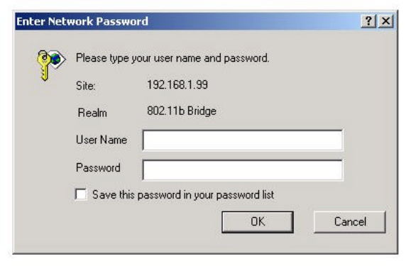
Open your web browser. (Internet Explorer 5.5 and 6.0 or Netscape 7.0 have been tested to work
properly. Other browsers may work but have not been verified.)
Open the following URL: 192.168.1.99 (select “try again” if the computer detects that you are
offline.)
The following window should appear:
The first time that you use this, just press OK. The User Name and Password will be set later.
17
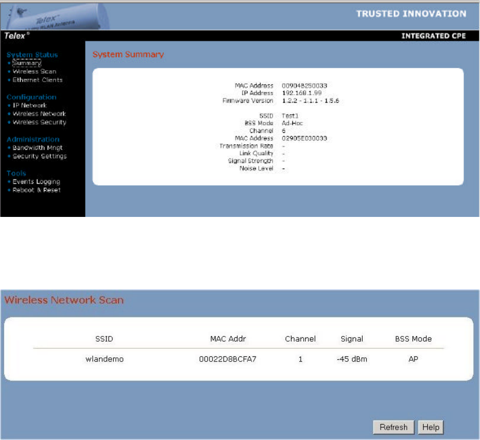
System Status
The following page should be displayed if no access points are available. Make sure that the
Firmware Version is current (see Chapter 7). Check the Telex website occasionally to check
for updates.
Select the Wireless Scan page to show available access points and their channel, signal level and
BSS Mode (including WEP). Press the Refresh button to update.
If your network SSID is shown in the Scan (e.g. wlandemo), then click on it to automatically
associate the CPE to this AP. After clicking on the SSID and clicking OK, the Status Page
should look like this:
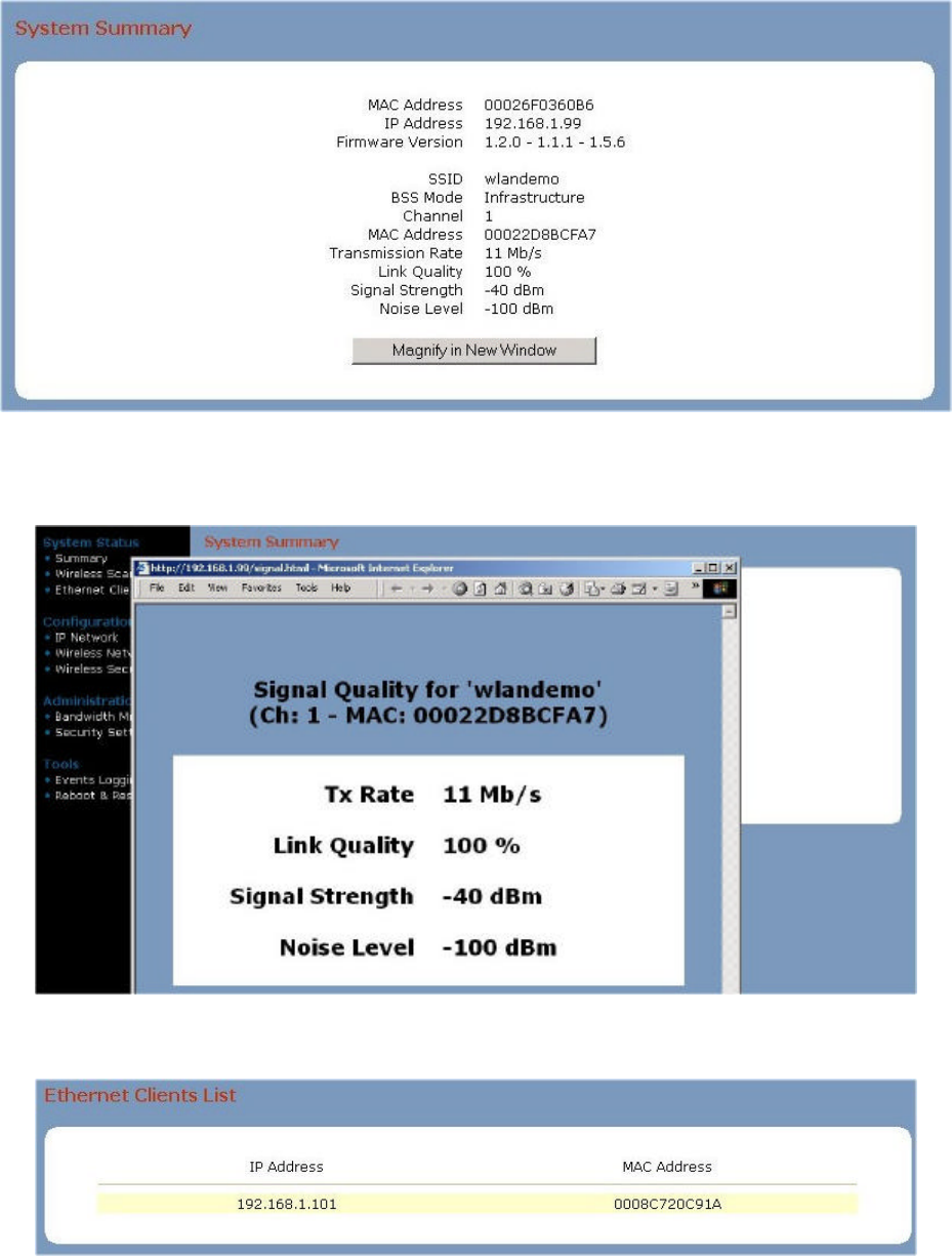
18
Click on Magnify in New Window to open a large font window for use in antenna aiming. This
window automatically updates every few seconds. It should look like this:
The Ethernet Clients page will show all computers currently wired to this CPE.
19
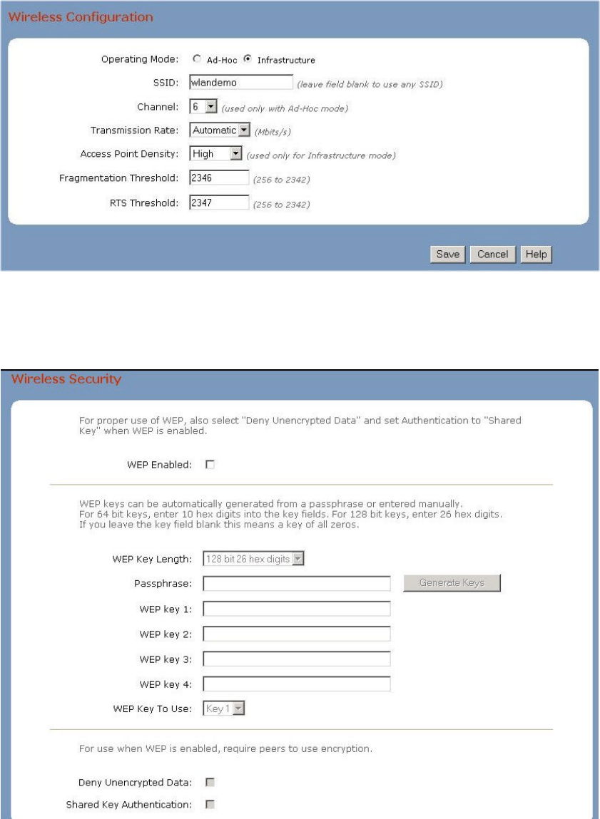
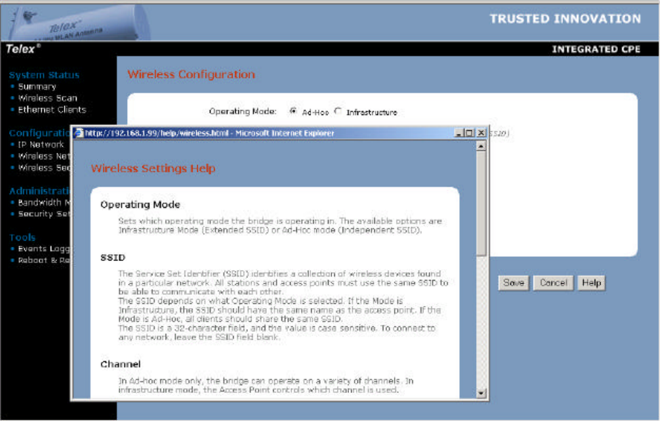
Configuration
To enter the SSID, Channel, Transmission Rate, Access Point Density or RTS information
manually, select the Wireless screen as shown below. For information on any selection, press the
Help page tab. Make any changes you require, then click Save.
To use standard WEP security, select the Security page tab shown below and select WEP
enabled. Choose from either 64 or 128 bit WEP Key Length, then enter the pass phrase. Make
sure that your access point uses the same WEP information.
20
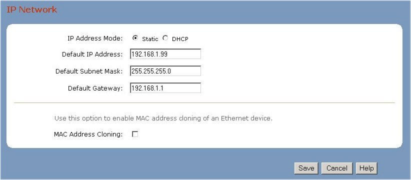
To set the IP Address of the CPE, use the IP Network configuration page as shown below. If
you change the CPE’s static IP address to a different subnet, make sure that you also change your
computer’s IP address after exiting the browser. Otherwise, the computer and CPE will not be
able to communicate with each other. They must be on the same subnet in order to see each
other. If you plan on having more than one CPE with a static IP on the same subnet, you MUST
change the last number of the IP address. You can also enable MAC address cloning on this
page.
IP Address: _____________________________
21
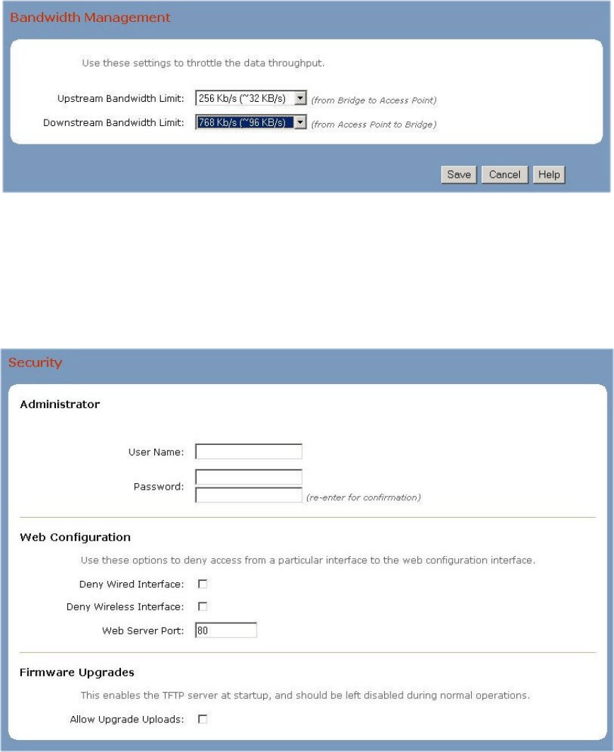
Administration
In the Bandwidth Management page shown below, you may set the Upstream and
Downstream bandwidth limits for this CPE.
In the Security Settings page shown below, you may set the User Name and Password for this
web interface. Make sure that you write down this information and store in a safe place so that it
is not forgotten or stolen. Any time that you wish to reset the CPE to factory defaults, click on
the Reset Configuration button on the Reboot & Reset page. The Security Settings page also
allows you to either Allow Upgrade Uploads or Not Allow. For normal operation, leave this
off. The Web Server Port may also be changed if required.
User Name: ______________________
Password: ________________________
22
Tools
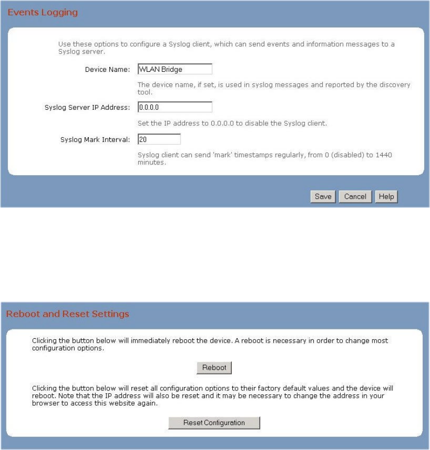
In the Events Logging page shown below, you may use these options to configure a Syslog
client, which can send events and information messages to a Syslog server.
In the Reboot & Reset page shown below, you may use the Reboot button to immediately
reboot the CPE. The Reset Configuration button will reset all configuration options to their
factory default values.
23
Help Pages
The Help pages are accessible from most Configuration, Administration and Tools pages by
pressing the Help button.
Remote Access
When all changes have been made and saved at the client CPE location, close the browser.
Subsequent changes may now be made from either the client location or anywhere on the
network as long as you are in the same subnet.
IMPORTANT: If you disassociate the CPE from the AP, either by changing a setting or by
resetting the CPE, you must reassociate the CPE from the client location.
24
Step 3: Reset Your Computer Network Settings
The last step in the CPE configuration is to reset your computer network settings so they match
the settings used by your CPE and your ISP’s or LAN’s access point. This step may be skipped
if no changes were made to the CPE IP address during Step 2.
a. Right-click on the Network icon (My Network Places) on your computer’s desktop and
select Properties from the pop-up menu.
b. Right-click on “Local Area Connection” and select Properties from the pop-up menu.
c. Select the installed TCP/IP protocol, then click the Properties button.
d. If using static IP addresses: Enter an IP Address for your computer that is different than
the CPE’s IP address. Usually, you can use an IP number that is one higher than the CPE
IP address. For example, if the CPE’s IP address is 192.168.1.99 then assign
192.168.1.100 to the computer. If you have many computers and CPE’s in your network,
then make sure that each uses a different IP address within the same subnet.
e. If using static IP addresses: Change your computer’s Subnet Mask and Default
Gateway settings to match the values you received from your ISP or IS Dept.
f. If you selected “Obtain an IP address automatically” in your computer, then the CPE
should transparently pass internet traffic to your computer. You will not be able to
change the CPE settings until you reset the computer to a static IP. Set the DNS Server
information if necessary.
g. Click on OK in each window to accept the changes.
h. Restart your computer if prompted.
i. If using a static IP on the CPE, open your web browser to the CPE’s IP address to ensure
that the computer can still talk to it.
25
Chapter 5: Managing the Wireless CPE
The initial association of the CPE with an access point must be performed at the client location.
However, once connected to the network, the CPE’s settings may be monitored and changed
from any computer on the same subnet.
From this remote computer, open the web browser and enter the CPE’s IP address as the URL.
You must know the User Name and Password for this CPE in order to log in and change the
settings.
Once logged-in, you may change anything except those items that affect the association of the
CPE with the rest of the network. If the association is lost, then you may only communicate with
the CPE from the local client computer.
These items may be easily changed:
Wireless Configuration:
Transmission Rate (to a lower value)
Access Point Density
Fragmentation Threshold
RTS Threshold – if the packet size is larger than this value, it will initiate the RTS/CTS function
Bandwidth Management:
Upstream Limit
Downstream Limit
Events Logging:
Device Name
Syslog Server IP Address
Syslog Mark Interval
Changes to all other items must be evaluated with respect to their effect upon device association.
After you have changed the item setting, press Save then Reboot.

26
Chapter 6: Troubleshooting
Problem:
After plugging in all cables and applying DC power to PoE, no lights come on.
Possible Causes / Solutions:
Cat-5 cable not wired to RJ45 plugs correctly. - Replace Cat-5 cable & check wiring
Cables plugged into wrong jacks of PoE box - use correct jacks
Defective power supply - Replace power supply
Defective PCB in CPE - Replace CPE unit
Defective PoE - Replace PoE box
Straight/Cross-over switch in wrong position - move switch to other position
Computer Network IP not set correctly - change Network IP to 192.168.1.100
Computer, hub, switch or router not turned on - turn on equipment
Computer Cat-5 cable not plugged-in - plug cable in
Cat-5 cable not wired correctly - Replace Cat-5 cable & check wiring
Defective PCB in CPE - Replace CPE unit
Problem:
First Green light is on and system tray shows connection to the NIC, but cannot load CPE log-in
page
Possible Causes / Solutions:
Proxy Server box checked on LAN settings – uncheck this box
Auto-negotiate function turned on in NIC – manually set to 10 Mbps
Problem:
First Green light is on but not second green light
Possible Causes / Solutions:
CPE is not associated with any Access Points - Set AP association, check status of AP
Problem:
“Click to Associate” does not work
Possible Causes / Solutions:
Older Version of Browser in use - Load Internet Explorer 5.5 or 6.0
Problem:
CPE initially associates with AP, but locks up after changing settings
Possible Causes / Solutions:
More than one computer with same IP address on subnet – change.
Check the CPE FAQ’s on the Telex Wireless web pages for helpful hints and troubleshooting
guides. (http://www.telex.com/Wireless/faq.nsf/c)
27
Chapter 7: Firmware Documentation
The current firmware is 1.2.5 - 1.1.1 – 1.5.6. This is Ethernet PCB firmware version 1.2.5 and
PRISM firmware 1.1.1 (primary) and 1.5.6 (secondary). To upgrade firmware, ensure that the
CPE and attached computer are on the same subnet, then run the supplied Locator tool.
1.2.5-1.1.1-1.5.6 Release Notes:
Default settings:
IP: 192.168.1.99
SSID: (empty)
No WEP, no user name, no password
Disallow firmware upgrades
1.2.5 (2 December 2003)
- Fixed a problem with TCP deadlocking when receiving data from a remote host but being
unable to make progress retransmitting a lost segment.
- Cleaned up web server’s error recovery on aborted requests.
- Added BSSID and RSSI to syslog mark messages.
- Improved RSSI and noise level dBm readings.
- Fixed wrong MAC address displayed by Locator.
- Now show the device the bridge is associated with on the Scan List page, but not
clickable.
- Changed the bandwidth control: now account for protocol headers (Ethernet, IP, TCP and
UDP) in the bandwidth calculation. Also, ICMP and IGMP packets are not bandwidth
limited anymore.
1.2.2 (25 August 2003)
- Fixed typos in help pages.
- Fixed web server port problem.
- Fixed a bunch of small items.
1.2.1 (25 July 2003)
- Fixed self-programming LED’s.
- Fixed typo in WEP help page.
- Fixed scan list signal level.
1.2.0 (22 July 2003)
- Added syslog client.
- Added ability to deny access to the web UI from Ethernet or WLAN.
- TFTP server disabled by default.
- Added support for Locator Utility Tool.
- Changed default settings for SSID to “none”.
28
Chapter 8: 2472AA Specifications
General:
Model Number 2472AA
Standard IEEE 802.11b, 802.3
Regulatory Certifications FCC Part 15
Mode Point-to-Point under Part 15.247
Channels 11 Channels (US, Canada)
Frequency Band 2.400 – 2.483 GHz
Radio Type Direct Sequence Spread Spectrum (DSSS)
Modulation CCK (11, 5.5 Mbps), DQPSK (2 Mbps), DBPSK (1 Mbps)
Radio Raw Data Rate 11, 5.5, 2 and 1 Mbps, Auto Fall-Back
Maximum LOS Range approx. 8 miles (13 km) at 20 dB SOM & 1 Mbps
Typical LOS Range approx. 3 miles (5 km) at 20 dB SOM & 11 Mbps
Security 64/128 bit WEP
Electrical Specifications:
Operating Voltage from 9 to 24 VDC, 12VDC supplied
Operating Current 200 mA standby, 250 mA max (TCP)
Radio conducted output power 17 dBm (50 mW)
Antenna gain 18 dBi
EIRP 35 dBm (3 watts)
Radio Sensitivity -81 dBm @ 11 Mbps, -83 dBm @ 5.5 Mbps
-87 dBm @ 2 Mbps, -89 dBm @ 1 Mbps
Environmental:
Temperature Range -40 to 140 F (storage), -20 to 125 F (operating)
Humidity 5% to 95% typical
Physical:
CPE Dimensions 14” x 15.75” x 1.75” (35.5 x 40 x 4.4 cm)
CPE Weight 4 lbs. (1.8 kg)
Wind Surface Area 1.5 sq. ft. (0.14 sq. m)