Bosch Security Systems DCNM-IDESKX DCNM-IDESK, DCNM-IDESKVID User Manual DCN HW en part 2
Bosch Security Systems BV DCNM-IDESK, DCNM-IDESKVID DCN HW en part 2
Contents
- 1. Users Manual
- 2. DCN_HW_en part 1
- 3. DCN_HW_en part 2
DCN_HW_en part 2
DICENTIS Installation material and tools | en 37
Bosch Security Systems B.V. Hardware Installation Manual 2018.09 | V1.8 |
DCNM-CB02-I
DCNM-CB02-I
DCNM-(A)PS
CAT-5E cable
DCNM-CB02-I
DCNM-CB02-I
Cable coupler used as interface
38 en | Installation material and tools DICENTIS
2018.09 | V1.8 | Hardware Installation Manual Bosch Security Systems B.V.
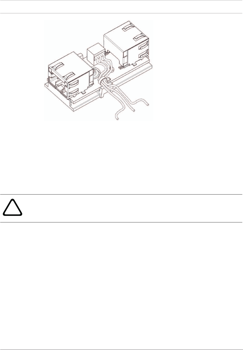
Figure5.3: Creating a tension relief, tie wrap prevents the power cables from being pulled out accidentally.
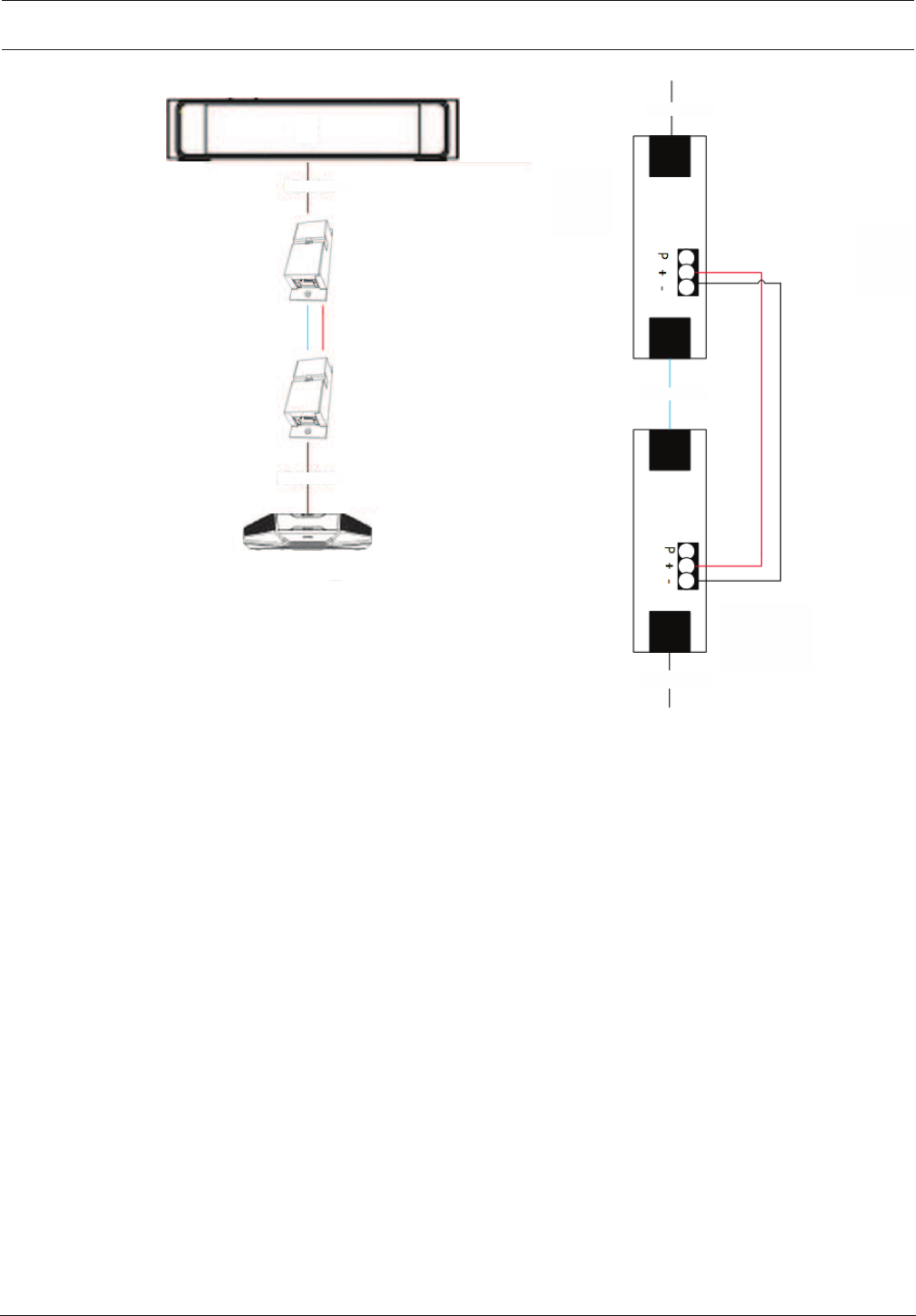
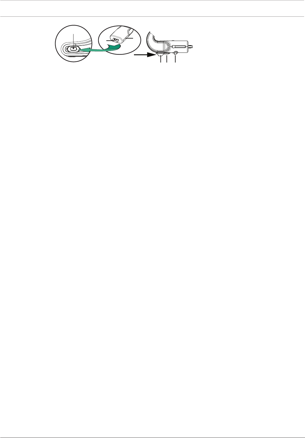
5.5.4 Using a cable coupler to insert power locally
The cable coupler can be used to insert a local power supply, enabling you to place a third-
party 48VDC power close to the participant devices.
To set this up:
1. Open the housing of the cable coupler.
2. Connect the power cables to the screw terminals + and -.
3. Remove the break-out of the housing to guide the power cables through.
4. Create a tension release.
!
Warning!
Risk of electric shock. Exposed power cables are a potential hazard. Make sure all power
cables are securely fastened by fixing them with a tie wrap on the inside of the box (see
drawing ‘Creating a tension relief’).
5. Close the housing and fix the screw with torque 0.4Nm.
Note:
– Requirements for the power supply:
– nominal output of 48VDC (ranging from 47-49VDC)
– the ripple should be less than 200 mV pk-pk
– maximum output current should not exceed 3.0A (or limited to 3.0A, because
DICENTIS cables and devices have a maximum rating for this current)
– Advice
– It is strongly advised that the power supply has its own short circuit protection with
a short circuit output current ranging from 4.3 to 5.0A.
– When the power supply has an automatic restart after a short circuit, this restart
function should have an interval time of 3 to 4 seconds and should have no more
than 4 restart attempts.
– Upon powering off the power supply, the output should be less than 9V, 1mA.
– The maximum distance between the (A)PS and the conference device is limited to 100m
due to the Ethernet properties.
DICENTIS Installation material and tools | en 39
Bosch Security Systems B.V. Hardware Installation Manual 2018.09 | V1.8 |
DCNM-(A)PS
CAT-5E cable
DCNM-CB02-I
48 VDC, 3A
power supply
CAT-5E cable
DCNM-CB02-I
48 VDC, 3A
power supply
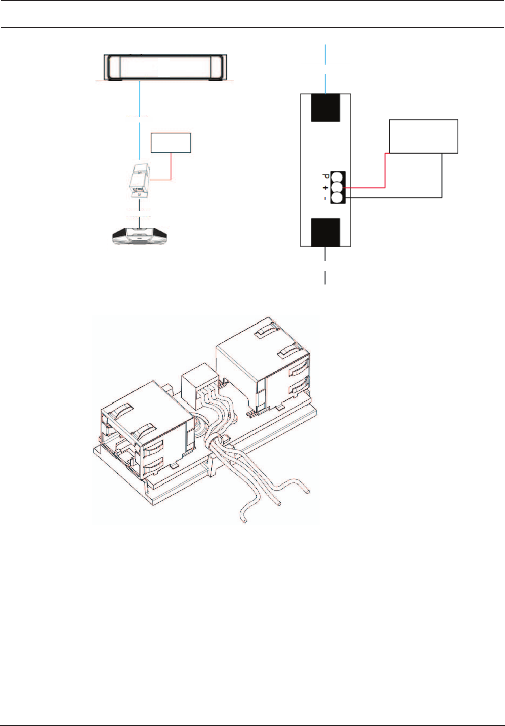
Transporting the power via cable
Figure5.4: Creating a tension relief, tie wrap prevents the power cables from being pulled out accidentally.
40 en | Mechanical installation of Central Equipment DICENTIS
2018.09 | V1.8 | Hardware Installation Manual Bosch Security Systems B.V.
6 Mechanical installation of Central Equipment
6.1 Audio processor and powering switch and Powering switch
The Audio processor and powering switch is used:
– to control system audio signals,
– to route audio signals to/from devices,
– to supply power to devices,
– as an Ethernet switch to connect the PC and DICENTIS devices (DCNM-D / DCNM-DVT /
DCNM-DSL / DCNM-DE / DCNM-MMD / DCNM-MMD2).
The Powering switch is used to:
– supply power to devices.
Scope of delivery
The Audio processor and powering switch and Powering switch are shipped with the following
parts:
– 1x Mains power cord.
– 1x Safety instructions.
– 1x Set of 19 inch mounting brackets.
– 4x bottom feet.
– 1x DVD containing manuals and software (only with Audio processor and powering
switch).
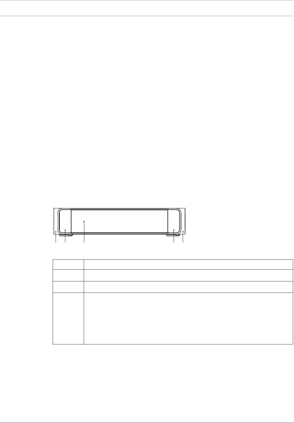
Front view
1 2 2 13
Figure6.1: Audio processor and powering switch / Powering switch
Item Description
1 19“ mounting brackets.
2 Ventilation inlet.
3Indication LED:
Off: Switched off.
Green: Switched on.
Amber: Standby.
Blinking: Services on the server PC are not running.
Alternating green amber: When a software download is required.
DICENTIS Mechanical installation of Central Equipment | en 41
Bosch Security Systems B.V. Hardware Installation Manual 2018.09 | V1.8 |
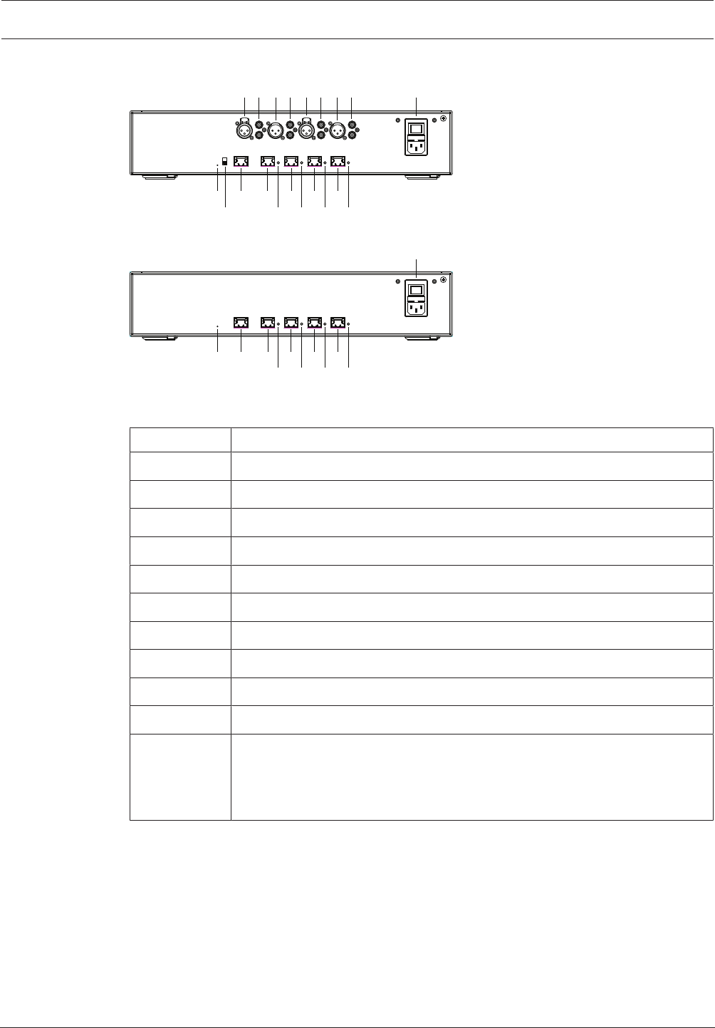
Rear view
10 12 13 15 17 19
11 14 16 18 20
1 2 3 4 5 6 7 8 9
Figure6.2: Audio processor and powering switch
10 12 13 15 17
14 16 18
19
20
9
Figure6.3: Powering switch
Item Description
1, 5 XLR line outputs 1 and 2.
2, 6 RCA line outputs 1 and 2.
3, 7 XLR line inputs 1 and 2.
4, 8 RCA line inputs 1 and 2.
9 Mains inlet, mains switch and fuse holder.
10 Reset button.
11 Ground switch (grounded or floating).
12 Socket 1 without power.
13 Socket 2 low power.
15, 17, 19 Socket 3, 4, 5 high power.
14, 16, 18, 20 Overload LED for sockets 2‑5:
Green: Power OK.
Red: Overload. Remove cable and wait a few seconds for the system to
reset the overload.
42 en | Mechanical installation of Central Equipment DICENTIS
2018.09 | V1.8 | Hardware Installation Manual Bosch Security Systems B.V.
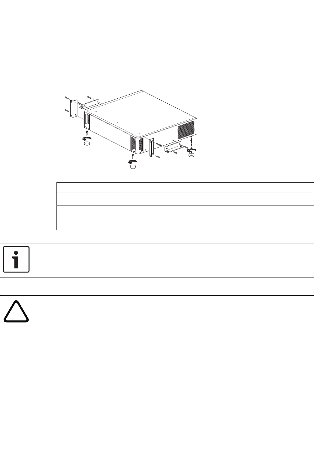
How to install
1. Install the Audio processor and powering switch or Powering switch in a 19 inch device
rack system or on a flat surface. Two 19 inch mounting brackets and four bottom feet are
supplied with the Audio processor and powering switch and Powering switch. Refer to
the following illustration.
2. Connect all required cabling.
3. Connect the mains supply.
1
2
3
Figure6.4: 19 inch rack, flat surface and feet mounting
Item Description
1 19 inch rack mounting (bracket)
2 Flat surface mounting (bracket)
3 Feet mounting
Notice!
The unit extends 30mm in front of the 19” mounting brackets when installed in a 19” rack
system.
!
Caution!
Do not obstruct the airflow vents on the front side and rear left and right sides.
DICENTIS Mechanical installation of Contribution Devices | en 43
Bosch Security Systems B.V. Hardware Installation Manual 2018.09 | V1.8 |
7 Mechanical installation of Contribution Devices
7.1 DICENTIS devices
The DICENTIS devices (DCNM-D, DCNM-DVT, DCNM-DSL, DCNM-DE, DCNM-MMD, DCNM-
MMD2) are used to:
– participate in a meeting or conference.
– monitor and control a meeting or conference (chairperson use, depending on the
configuration).
DCNM-MMD / DCNM-MMD2
1
4
5
78 6
9
10
3
2
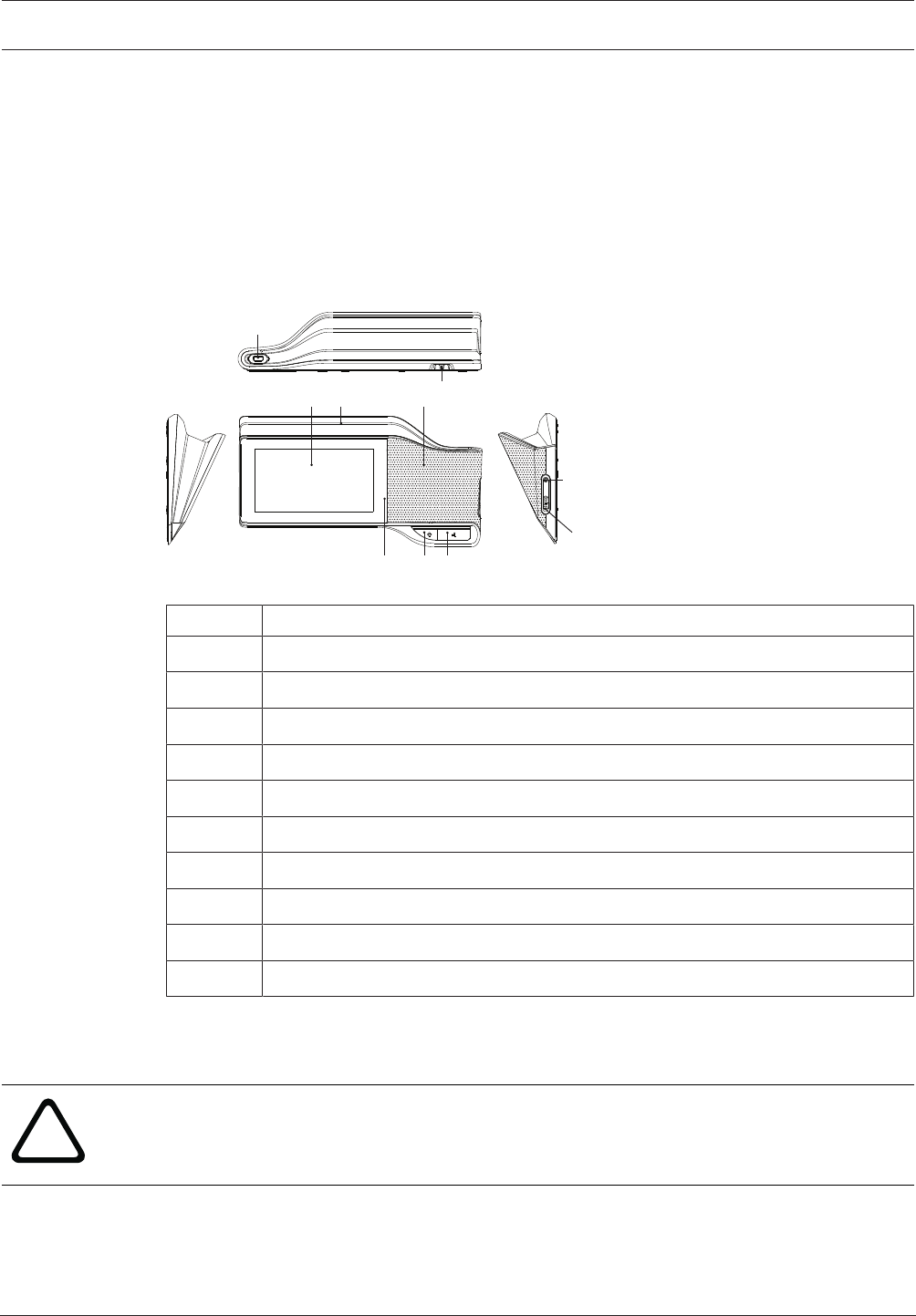
Figure7.1: Front, top, rear and side views
Item Description
1 7” capacitive touch screen.
2 LED strip.
3 Two‑way loudspeaker.
4 3.5 mm stereo jack for headphone or headset with integrated microphone.
5 Headphone volume control.
6 Microphone request button.
7 Chairperson priority or microphone mute button.
8 Near Field Communication (NFC) reader (DCNM-MMD2 only).
9 Cable guides.
10 Microphone input connector.
– DCNM-MMD2 is compliant with the Radio Equipment Directive (RED) 2014/53/EU.
– Operating frequency is 13.56 MHz. Maximum field strength is 8.05 dBµA/m @ 3m.
!
Warning!
This equipment is compliant with Class A of CISPR 32. In a residential environment this
equipment may cause radio interference. This equipment is intended for environment Class A.
44 en | Mechanical installation of Contribution Devices DICENTIS
2018.09 | V1.8 | Hardware Installation Manual Bosch Security Systems B.V.
DCNM-D / DCNM-DVT / DCNM-DSL / DCNM-DE
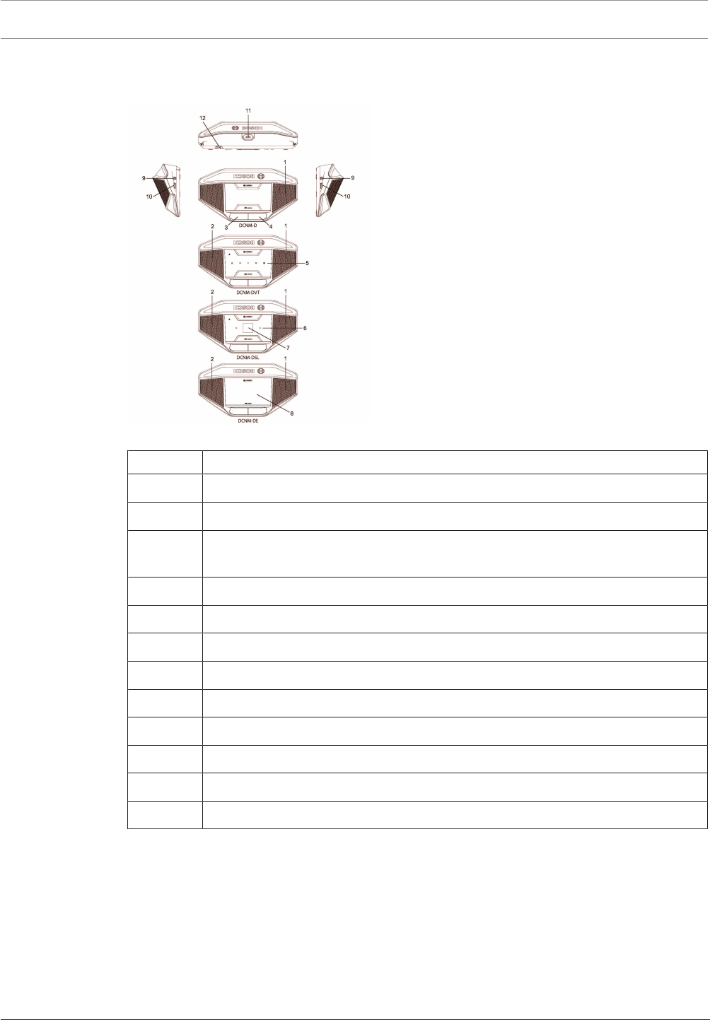
Figure7.2: Front, top, rear and side views
Item Description
1 Two‑way loudspeaker.
2 Near Field Communication (NFC) reader.
3 Chairperson priority button, microphone mute button, or microphone request
button for second participant.
4 Microphone request button.
5 Voting buttons.
6 Language selection buttons.
7 Language display.
8 4.3” capacitive touch screen.
9 3.5 mm stereo jack for headphone or headset with integrated microphone.
10 Headphone volume control.
11 Microphone input connector.
12 Cable guides.
– DCNM-DE, DCNM-DVT and DCNM-DSL are compliant with the Radio Equipment Directive
(RED) 2014/53/EU.
– Operating frequency is 13.56 MHz. Maximum field strength is -8.4 dBµA/m @ 10m.
DICENTIS Mechanical installation of Contribution Devices | en 45
Bosch Security Systems B.V. Hardware Installation Manual 2018.09 | V1.8 |
Connecting DICENTIS devices
The DICENTIS Conference System can be quickly and easily configured as a daisy‑chain
configuration or as a star configuration:
–Daisy‑chain configuration: Uses dedicated cabling, consisting of CAT‑5e cables including
two additional power conductors (see Typical system setup, page 10).
–Star configuration: Each DICENTIS device is connected with an individual standard
CAT‑5e cable. An Ethernet switch is also required for providing Power over Ethernet
(PoE).
Notice!
When Power over Ethernet is used, DICENTIS devices cannot be daisy‑chained. Please use
unshielded cable for the DICENTIS discussion devices.
The star configuration makes use of connectors underneath the devices, ensuring for a neat,
tidy system installation, especially advantageous for TV coverage.
To connect the system network cables to the DICENTIS devices (refer to the following figure):
1. Insert the system network cable/connector (2).
2. Lead the system network cable through the cable guides (3).
Installing DICENTIS devices
The DICENTIS devices can be free-standing or fixed in more permanent installations using
mounting screws.
1. The distance between the centres of the screw inserts (1) on the bottom is 100mm.
2. Use M4 type of screws with a device screw insert length of maximum 5mm when
attaching the device to the bottom of the recess (1).
3 4
11
2
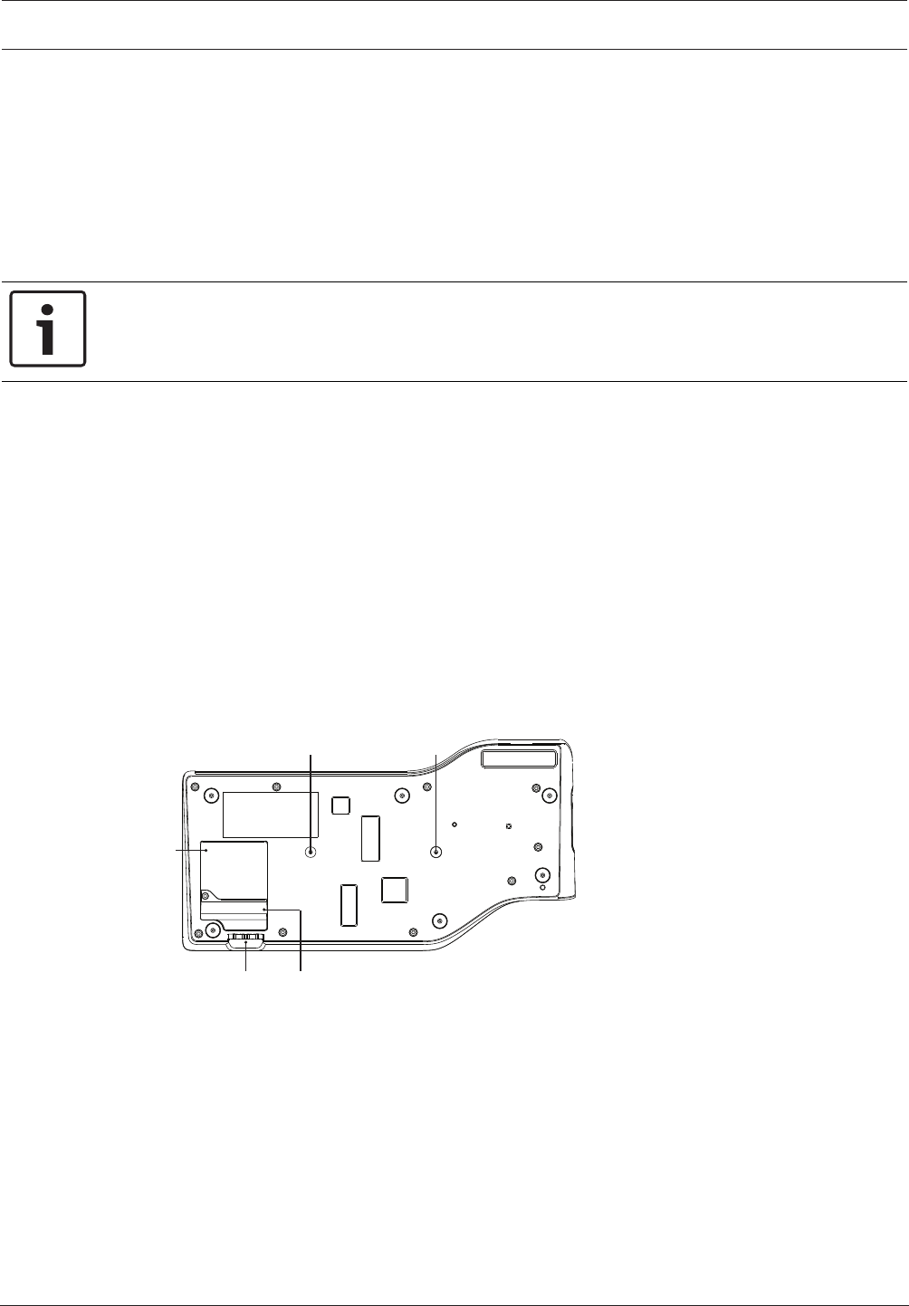
Figure7.3: Bottom view discussion DICENTIS devices (DCNM-MMD / DCNM-MMD2)
46 en | Mechanical installation of Contribution Devices DICENTIS
2018.09 | V1.8 | Hardware Installation Manual Bosch Security Systems B.V.
1 1
32
Figure7.4: Bottom view DICENTIS devices (DCNM-D / DCNM-DVT / DCNM-DSL / DCNM-DE)
Item Description
1 Screw insert for fixed installation.
2 2x RJ45 connection input/output for system power cable.
3 Cable guides.
4 USB connector, for future use (DCNM-MMD / DCNM-MMD2 only).
See also
– DICENTIS System Cable Assemblies, page 31
– DCNM-CB250-I System Installation Cable, page 34
7.2 DCNMM-IDESK / DCNM-IDESKVID Interpreter desk
The Interpreter desks (DCNM-IDESK and DCNM-IDESKVID) are used to:
– interpret the floor language (channel A) in a meeting or conference,
– relay the interpretation to various target languages via channel selection (channel B or C).
1
2
3
4
5
6 710
11
8
912 13
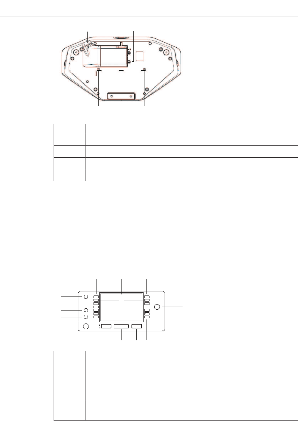
b B
Item Description
1Loudspeaker volume knob - Adjusts the volume level of the signal that is sent to
the loudspeaker of the interpreter desk.
2Treble knob - Adjusts the level of the treble of the signal that is sent to the
headphones.
3Bass knob - Adjusts the level of the bass of the signal that is sent to the
headphones.
DICENTIS Mechanical installation of Contribution Devices | en 47
Bosch Security Systems B.V. Hardware Installation Manual 2018.09 | V1.8 |
Item Description
4Headphones volume knob - Adjusts the volume level of the signal that is sent to
the headphones.
5Menu knob -Rotary control with integrated push button to configure and operate
the interpreter desk.
6Pre-select buttons - Allows the interpreters to select a channel from which they
can render an interpretation (input).
7Output buttons - Sets the output the target language will be sent to (A, B, C).
8b - B buttons - Press these 2 buttons (with a small raised dash) at the same time
to enter the installation mode and assign the device to a booth and desk. See
“DICENTIS Software manual”, chapter 9 on how to configure the interpreter
desk.
9Assignable buttons - 3 buttons that can be freely assigned
10 Display - Shows the configuration, user menus and provides user feedback.
11 Floor/Auto-relay button - Sets the source of the interpretation.
12 Microphone button - Enables or disables the microphone. The microphone
button has a red LED that comes on when the microphone is enabled (on-air). A
green LED shows that the booth is not in use.
13 Mute button - Temporarily disables the microphone.
Connecting Interpreter desks
Two RJ45 compatible connections for system communication and power are available for
quick and easy connection of the interpreter desks. Loop-through cabling can be applied by
using DICENTIS System cables or star cabling using standard CAT-5e cables and PoE switches.
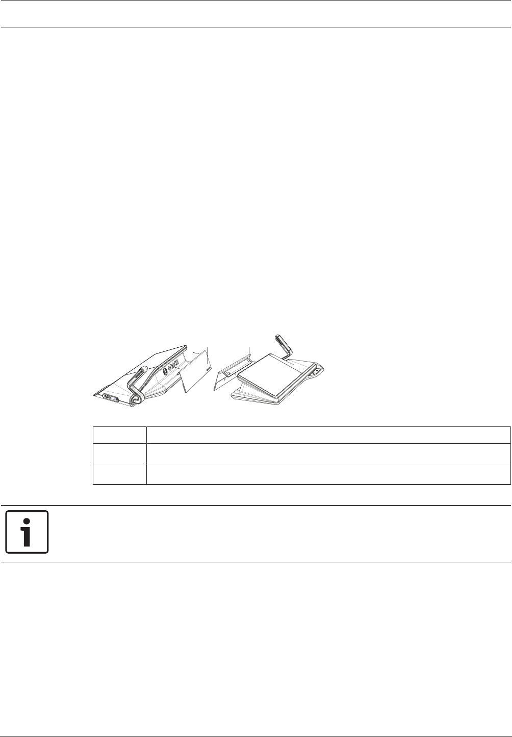
Installing Interpreter desks
The interpreter desks can be installed free-standing or fixed in more permanent installations
(table-top) using mounting screws.
!
Warning!
The screws must be M3 and should not be screwed in deeper than 5 mm (0.2 inches) to avoid
damaging the device.
11
2 34
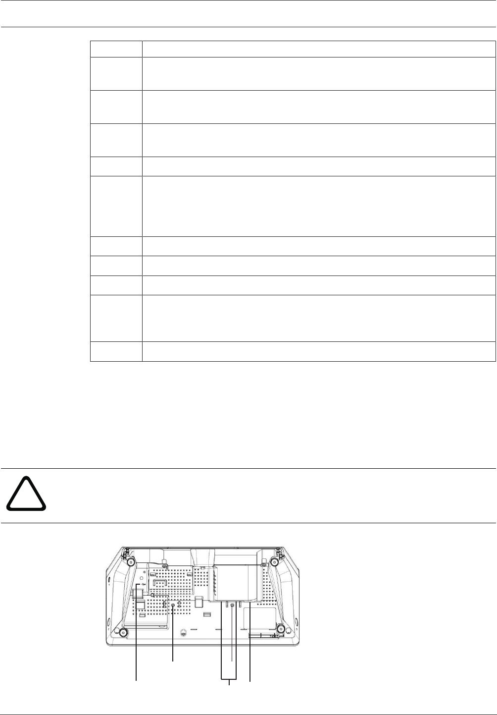
Figure7.5: DCNM-IDESK / DCNM-IDESKVID bottom view

48 en | Mechanical installation of Contribution Devices DICENTIS
2018.09 | V1.8 | Hardware Installation Manual Bosch Security Systems B.V.
Item Description
1 Screw insert for fixed installation
2 2 x RJ45 connection input/output for system power cable
3 HDMI video output (DCNM-IDESKVID only)
4 USB connector for the DCNM-IDESKINT On-air & telephone interface DCNM-
IDESK. Refer to section 7.6
DICENTIS Mechanical installation of Contribution Devices | en 49
Bosch Security Systems B.V. Hardware Installation Manual 2018.09 | V1.8 |
7.3 DICENTIS Microphones
Both the DCNM‑HDMIC High Directive Microphone and DCNM-MICL/S Stem Microphone are
typically used with the DICENTIS devices.
3
64
7
1
2
5
8
2
6
4
7
1
2
5
8
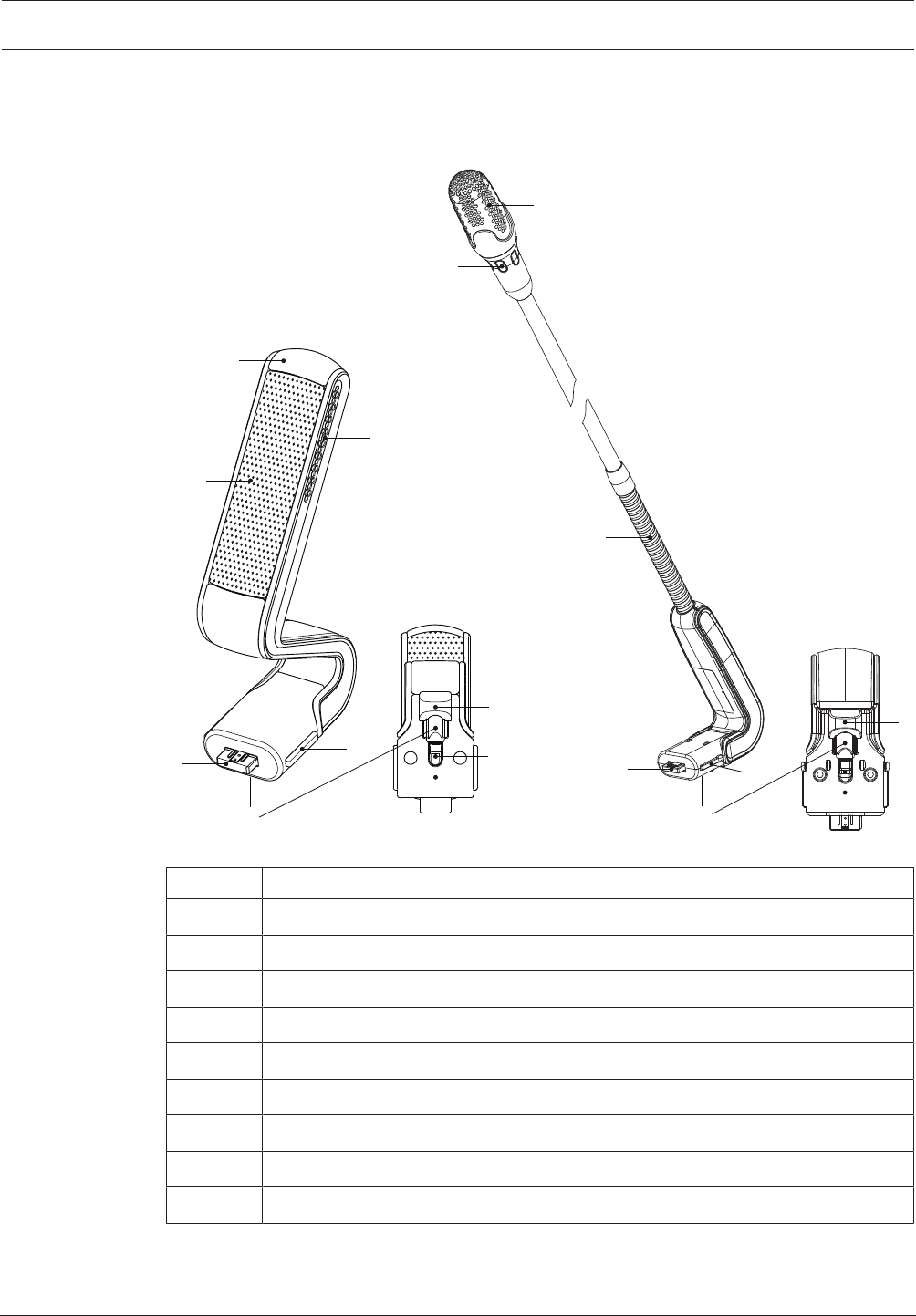
Figure7.6: DCNM‑HDMIC and DCNM‑MICS/DCNM‑MICL front and bottom view
Number Description
1 LED indicator.
2 Microphone grill.
3 Adjustable stem (DCNM‑MICS/DCNM‑MICL).
4 Connection guidance.
5 Slider guidance.
6 Connector plug.
7 Lock-slider for lock release (Press and shift to release).
8 Lock.
9 Device female connector (see following figure).
How to connect or remove the microphone
The microphone can be easily connected to the DICENTIS devices:
50 en | Mechanical installation of Contribution Devices DICENTIS
2018.09 | V1.8 | Hardware Installation Manual Bosch Security Systems B.V.
9
64
857
Figure7.7: DCNM‑HDMIC or DCNM-MICS/DCNM-MICL connection
To do so:
1. Gently guide the connection guidance (4) into the DICENTIS device microphone
connector (9).
2. Gently push the connector plug (6) into the device microphone connector (9) until the
connection lock (5) fits/click into place.
3. To remove the microphone from the device: Shift lockslider (7) towards the device and
hold in place lock release (8) and pull out the microphone.
See also
– DICENTIS devices, page 43
DICENTIS Mechanical installation of Contribution Devices | en 51
Bosch Security Systems B.V. Hardware Installation Manual 2018.09 | V1.8 |
7.4 DCNM-MMDSP Anti-reflection foil
The DICENTIS anti‑reflection foil can be used to protect the tempered glass screen of a
DICENTIS multimedia Device.
Installation procedure
1. Use the included alcohol swab and the microfiber fabric to clean the device LCD screen
before installation.
2. Peel the positioning adhesive release paper from the rear of anti‑reflection foil.
3. Position the anti‑reflection foil on the device LCD screen, and then fix the positioning
adhesive to the side of the device.
4. Open the anti‑reflection foil, and use the “cleaning stick” to clean surface dust from the
LCD screen.
5. Peel the protective film from the other side of the anti‑reflection foil.
6. Lightly press the anti‑reflection foil on to the LCD screen. If air bubbles are trapped under
the anti‑reflection foil, use the “squeegee” to remove them.
7.5 DCNM-NCH Name Card Holder
The name card holder (1) can be used to permanently display the participant’s name on the
rear of a DICENTIS multimedia Device. The name card holder has two magnets (2) that allow it
to be easily attached to, and removed from, the rear of the device.
12
2
Figure7.8: DCNM‑NCH assembly
Item Description
1 Name card holder.
2 Magnets.
Notice!
A paper insert template is included on the DVD that can be downloaded at: https://
licensing.boschsecurity.com/software

52 en | Mechanical installation of Contribution Devices DICENTIS
2018.09 | V1.8 | Hardware Installation Manual Bosch Security Systems B.V.
7.6 DCNM-IDESKINT On-air & telephone interface DCNM-IDESK
This interface is used to control a booth on-air light and to show a telephone ringing indicator.
The interface is connected to the USB port of one of the DCNM-IDESK devices inside the
booth.
The USB cable must be purchased separately.
DICENTIS Installation Test | en 53
Bosch Security Systems B.V. Hardware Installation Manual 2018.09 | V1.8 |
8 Installation Test
An installation test is needed to prevent connection mismatches and find potential product
defects at an early stage. Not to do so could result in a system malfunctioning.
Each DICENTIS device has its own built‑in diagnostics, which can be used for faultfinding. The
diagnostics starts as soon the DICENTIS device is powered on. The DICENTIS Conference
System does not have to be configured with, and connected to, the system controller PC.
Preconditions
1. All system network cables are connected to the devices.
2. The Audio processor and powering switch and Powering switch(es) are installed.
Start the test
Power on the Audio processor and powering switches and Powering switches used in the
system: Each connected device powers on and initializes.
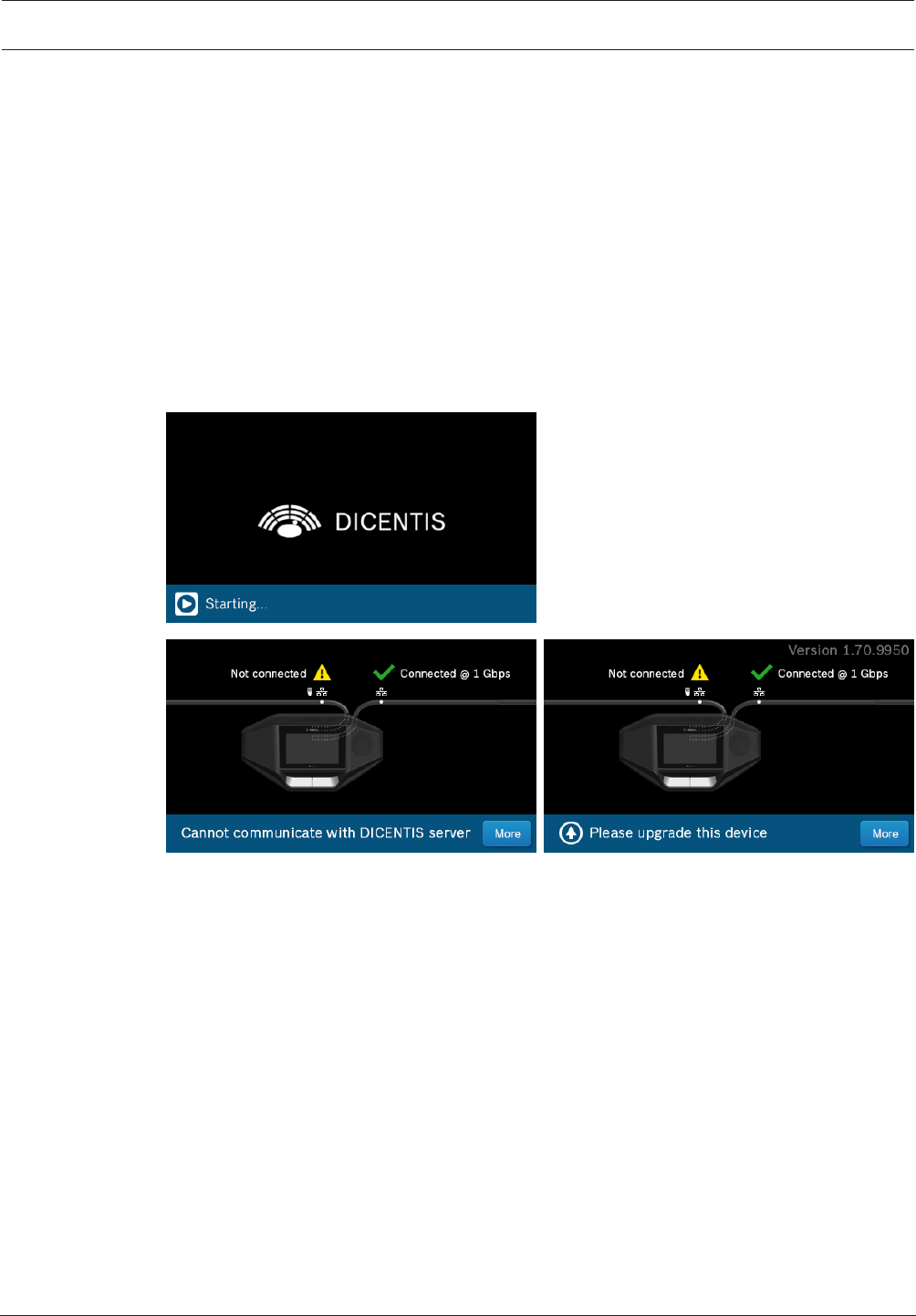
1. After the DICENTIS multimedia Device / the DICENTIS discussion Extended have
initialized, the diagnostic screen is shown.
2. If the text “Link down” is shown:
– The network cable is not connected or defective.
– The device is only connected with one system network cable (“Link down” is shown
on the side where the device is not connected).
3. If the system network cable is correctly connected to the network, the network speed is
shown.
4. If the DICENTIS multimedia Device / the DICENTIS discussion Extended are connected to
an Audio processor and powering switch, Powering switch or another multimedia device,
and 100Mb is shown:
– Not all wiring inside the system network cable connector is correctly connected or
broken. You need to check the wiring and connector.
– If the cable is connected to a 100Mb switch, it is correct.
5. Click the info button to see additional information of the multimedia device.
6. When everything is correctly connected, and the device does not have the application
software, it shows the text “Please download software”.
7. Now the device can be downloaded:

54 en | Installation Test DICENTIS
2018.09 | V1.8 | Hardware Installation Manual Bosch Security Systems B.V.
– Downloading devices is not covered in this manual. Refer to the DICENTIS
configuration manual on how to download the devices.
Customer service
If a fault cannot be resolved, please contact your supplier or system integrator, or go directly
to your Bosch representative.

Bosch Security Systems B.V.
Torenallee 49
5617 BA Eindhoven
Netherlands
www.boschsecurity.com
© Bosch Security Systems B.V., 2018