Bosch Security Systems DCNM-IDESKX DCNM-IDESK, DCNM-IDESKVID User Manual DCN HW en part 1
Bosch Security Systems BV DCNM-IDESK, DCNM-IDESKVID DCN HW en part 1
Contents
- 1. Users Manual
- 2. DCN_HW_en part 1
- 3. DCN_HW_en part 2
DCN_HW_en part 1
DICENTIS
Conference System
en Hardware Installation Manual

DICENTIS Table of contents | en 3
Bosch Security Systems B.V. Hardware Installation Manual 2018.09 | V1.8 |
Table of contents
1Safety 4
2About this manual 6
2.1 Intended audience 6
2.2 Alerts and notice signs 6
2.3 Copyright and disclaimer 6
2.4 Document history 6
3System installation overview 9
3.1 Typical system setup 10
3.2 System extension 13
4System installation design and planning 17
4.1 System capabilities 17
4.2 Hardware requirements 19
4.3 Power supply capacity calculation plan 22
4.3.1 Calculation using DCNM-APS(2) or DCNM-PS(2) 22
4.3.2 Calculation using PoE switches 24
4.4 Redundancy options 26
4.4.1 Redundant cabling for DCNM‑APS/DCNM‑PS units 27
4.4.2 Redundant cabling for DCNM-APS2/DCNM-PS2 units 28
4.4.3 Redundant server PC 30
5Installation material and tools 31
5.1 DICENTIS System Cable Assemblies 31
5.2 DCNM-CBCON Connectors for DICENTIS cable 32
5.3 DCNM-CBTK System Network Cable Toolkit 33
5.4 DCNM-CB250-I System Installation Cable 34
5.5 DCNM-CBCPLR Cable couplers 35
5.5.1 Using a cable coupler to extend a cable 35
5.5.2 Using a cable coupler as a break-out box 35
5.5.3 Using a cable coupler as an interface between different types of cable 36
5.5.4 Using a cable coupler to insert power locally 38
6Mechanical installation of Central Equipment 40
6.1 Audio processor and powering switch and Powering switch 40
7Mechanical installation of Contribution Devices 43
7.1 DICENTIS devices 43
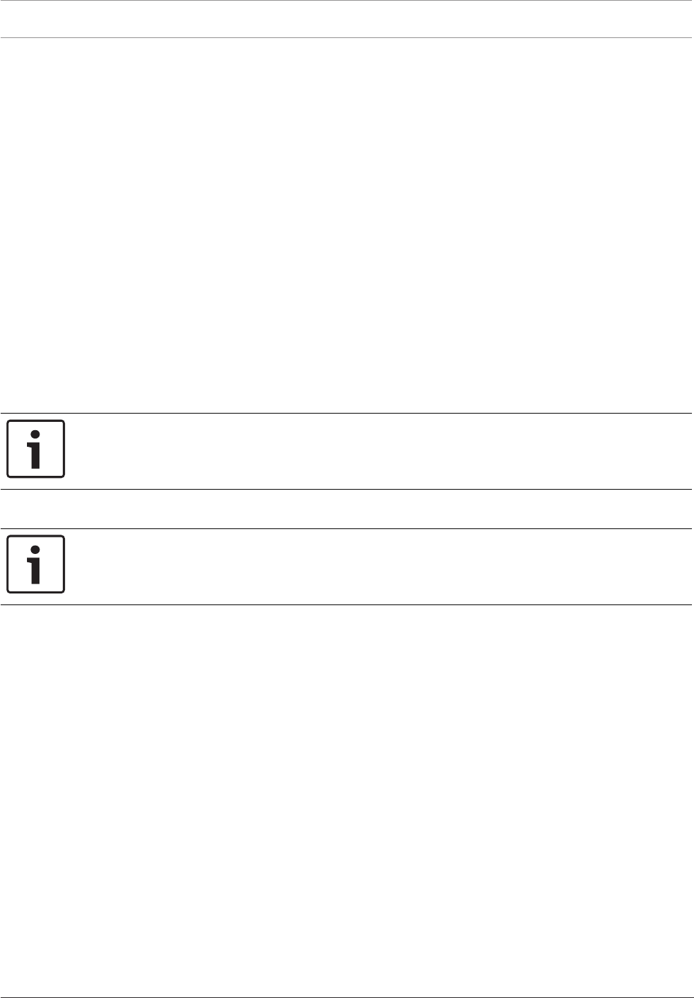
7.2 DCNMM-IDESK / DCNM-IDESKVID Interpreter desk 46
7.3 DICENTIS Microphones 49
7.4 DCNM-MMDSP Anti-reflection foil 51
7.5 DCNM-NCH Name Card Holder 51
7.6 DCNM-IDESKINT On-air & telephone interface DCNM-IDESK 52
8Installation Test 53
4en | Safety DICENTIS
2018.09 | V1.8 | Hardware Installation Manual Bosch Security Systems B.V.
1 Safety
Prior to installing or operating products, always read the Important Safety Instructions which
are available as a separate multilingual document: Important Safety Instructions (Safety_ML).
These instructions are supplied together with all equipment that can be connected to the
mains supply.
Safety precautions
Some of the DICENTIS Conference System products are designed to be connected to the
public mains network.
To avoid any risk of electric shock, all interventions must be carried out with disconnected
mains supply.
Interventions with the equipment switched on are authorized only when it is impossible to
switch the equipment off. The operation must only be performed by qualified personnel.
Old electrical and electronic appliances
Electrical or electronic devices that are no longer serviceable must be collected separately and
sent for environmentally compatible recycling (in accordance with the European Waste
Electrical and Electronic Equipment Directive).
To dispose of old electrical or electronic devices, you should use the return and collection
systems put in place in the country concerned.
Class A equipment (commercial broadcasting equipment)
This equipment is for professional (Class A) electromagnetic compatibility equipment. Seller
or user should pay attention to this point. It is intended for use outside the home.
!
Warning!
Changes or modifications not expressly approved by Bosch Security Systems could void the
user’s authority to operate the equipment.
FCC Statements - Class A digital device
This equipment has been tested and found to comply with the limits for a Class A digital
device, pursuant to part 15 of the FCC Rules. These limits are designed to provide reasonable
protection against harmful interference when the equipment is operated in a commercial
environment. This equipment generates, uses, and can radiate radio frequency energy and, if
not installed and used in accordance with the instruction manual, may cause harmful
interference to radio communications. Operation of this equipment in a residential area is
likely to cause harmful interference in which case the user will be required to correct the
interference at his/her own expense.
IC Statement
This device complies with Industry Canada license-exempt RSS standard(s). Operation is
subject to the following two conditions:
(1) this device may not cause interference, and
(2) this device must accept any interference, including interference that may cause undesired
operation of the device.
Le présent appareil est conforme aux CNR d'Industrie Canada applicables aux appareils radio
exempts de licence. L'exploitation est autorisée aux deux conditions suivantes :
(1) l'appareil ne doit pas produire de brouillage, et

DICENTIS Safety | en 5
Bosch Security Systems B.V. Hardware Installation Manual 2018.09 | V1.8 |
(2) l'utilisateur de l'appareil doit accepter tout brouillage radioélectrique subi, même si le
brouillage est susceptible d'en compromettre le fonctionnement.
6en | About this manual DICENTIS
2018.09 | V1.8 | Hardware Installation Manual Bosch Security Systems B.V.
2 About this manual
The purpose of this manual is to provide information required for installing the DICENTIS
Conference System.
This installation manual is available as a digital document in the Adobe portable document
format (PDF).
For more information, refer to the product related information on www.boschsecurity.com
2.1 Intended audience
This hardware installation manual is intended for installers of a DICENTIS Conference System.
2.2 Alerts and notice signs
Four types of signs can be used in this manual. The type is closely related to the effect that
may be caused if it is not observed. These signs - from least severe effect to most severe
effect - are:
Notice!
Containing additional information. Usually, not observing a ‘notice’ does not result in damage
to the equipment or personal injuries.
!
Caution!
The equipment or the property can be damaged, or persons can be lightly injured if the alert
is not observed.
!
Warning!
The equipment or the property can be seriously damaged, or persons can be severely injured
if the alert is not observed.
Danger!
Not observing the alert can lead to severe injuries or death.
2.3 Copyright and disclaimer
All rights reserved. No part of this document may be reproduced or transmitted in any form by
any means, electronic, mechanical, photocopying, recording, or otherwise, without the prior
written permission of the publisher. For information on getting permission for reprints and
excerpts, contact Bosch Security Systems B.V..
The content and illustrations are subject to change without prior notice.
2.4 Document history
Release date Documentation version Reason
2013.08 V1.0 1st edition.
2014.07 V1.1 2nd edition.
New sections: 1 WEEE, 3.2
system ext, 5.2.1, 5.2.2.

DICENTIS About this manual | en 7
Bosch Security Systems B.V. Hardware Installation Manual 2018.09 | V1.8 |
Release date Documentation version Reason
Sections updated: 2.4, 4.3.2,
5.2, 5.3, 5.4, 7.2 +
DCNM‑MICx added.
2014.10 V1.2 3rd edition.
Sections updated: 2.4, 3.2,
4.1 and 4.3.1.
2015.07 V1.3 4th edition.
New section: 4.4, including
sub-sections: 4.4.1, 4.4.2, and
4.4.3.
Sections updated: 2.4, 3.1,
3.2, 4.1, 4.3, 4.3.1, 5.3, 5.4,
6.1, 7.4, 8.
2015.11 V1.31 5th edition.
Sections updated: 2.4, 7.1.
Terminology updated.
2016.07 V1.4 6th edition.
Terminology updated.
DCN multimedia changed to
DICENTIS .
Sections updated: 3.1, 3.2,
4.1, 4.3.1, 4.3.2, 4.4.1, 4.4.2,
4.4.3, 5.3, 5.4, 7.1, 7.2, 7.3,
7.4, 8.
2017.10 V1.5 7th edition.
Terminology and product
names updated.
New section: 5.5
Sections updated: 5.2.1,
5.2.2, 7.1 new radio
interference warning added.
2017.12 V1.6 8th edition.
Sections updated: 5.5.3,
5.5.4.
2018.04 V1.7 9th edition.
Sections updated: 3.1, 3.2,
4.3.1, 4.3.2, 4.4, 5.2, 5.4,
5.5.4.
New section: 7.2 DCNM-
IDESK and DCNM-IDESKVID
Interpreter desk added.
2018.09 V1.8 10th edition.
Sections updated: 1, 7.2.

8en | About this manual DICENTIS
2018.09 | V1.8 | Hardware Installation Manual Bosch Security Systems B.V.
Release date Documentation version Reason
New section: 7.2 DCNM-
IDESKINT On-air & telephone
interface DCNM-IDESK

DICENTIS System installation overview | en 9
Bosch Security Systems B.V. Hardware Installation Manual 2018.09 | V1.8 |
3 System installation overview
It is advisable to participate in the DICENTIS Conference System training before you install,
configure, prepare, and operate a DICENTIS Conference System.
The DICENTIS Conference System is an IP based conference system which runs on an OMNEO
compatible Ethernet network. It is used for distributing and processing audio, video and data
signals.
The DICENTIS Conference System can be quickly and easily configured as a daisy‑chain
configuration or as a star configuration:
–Daisy‑chain configuration: Uses dedicated cabling, consisting of CAT‑5e cables including
two additional power conductors (see Typical system setup, page 10).
–Star configuration: Each DICENTIS device is connected with an individual standard
CAT‑5e cable. An Ethernet switch is also required for providing Power over Ethernet
(PoE).
Notice!
When Power over Ethernet is used, DICENTIS devices cannot be daisy‑chained. Please use
unshielded cable for the DICENTIS discussion devices.
See also
– Typical system setup, page 10
10 en | System installation overview DICENTIS
2018.09 | V1.8 | Hardware Installation Manual Bosch Security Systems B.V.
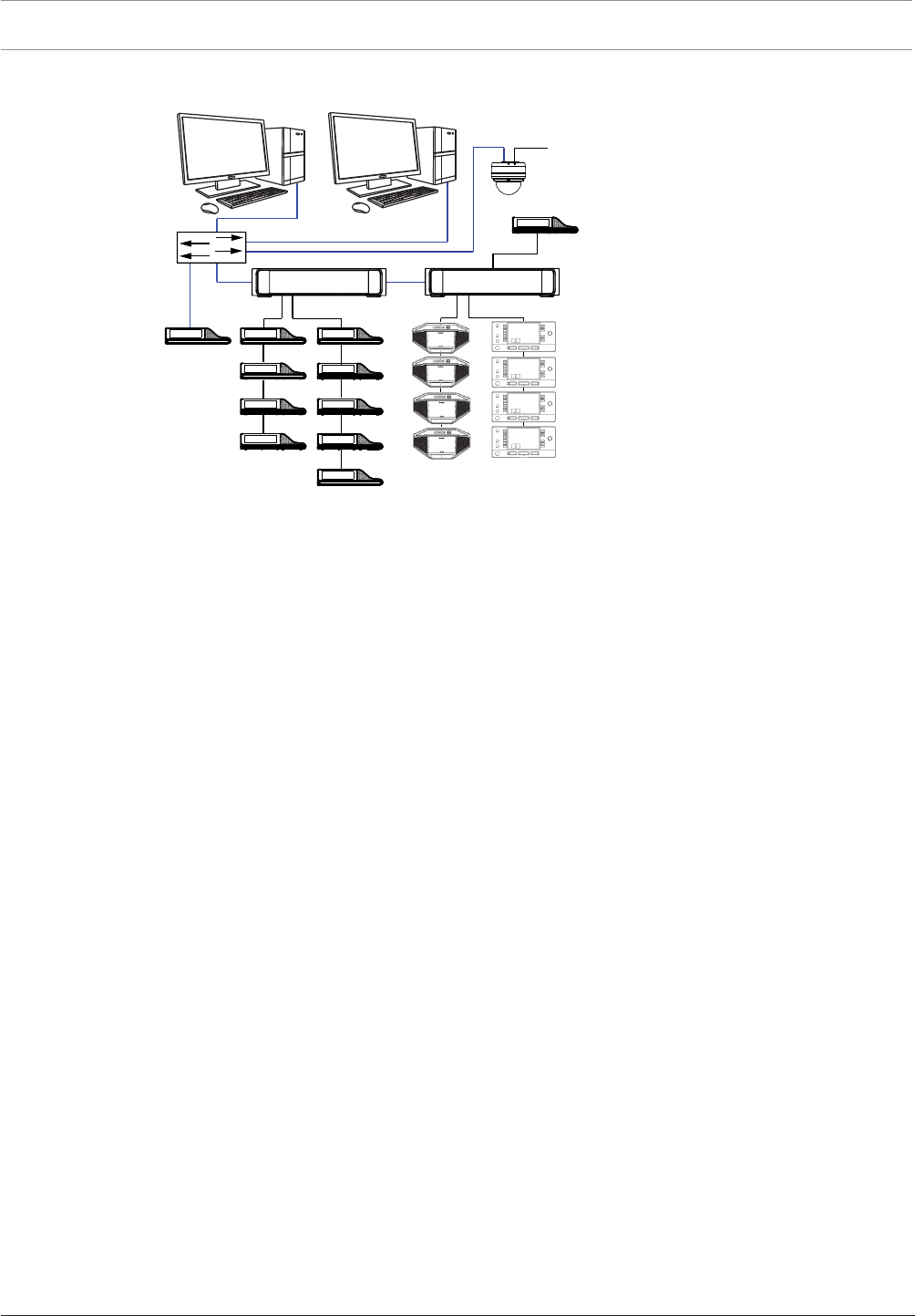
3.1 Typical system setup
1
8
2
43
9
8
8
6666
5
8
8
8
7
6
5.1
5.2
Figure3.1: Typical DICENTIS Conference System setup
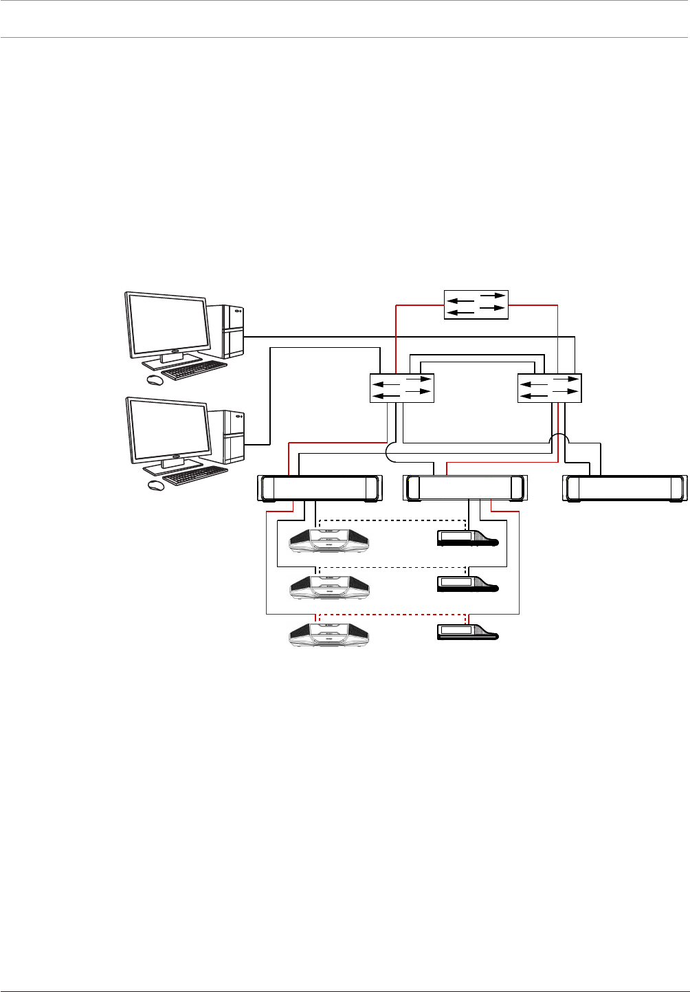
A typical DICENTIS Conference System consists of:
1. System server controller (PC):
– The heart of the system. It licenses functionality, configures and controls the system.
2. Client PC:
– Can be used to: Manage meetings, prepare meetings and configure the system.
3. Audio processor and powering switch (DCNM-APS / DCNM-APS2):
– Controls the system audio, routes audio from and to the system and supplies power
to the DICENTIS devices.
4. Powering switch (DCNM-PS / DCNM-PS2):
– Is used to increase the number of DICENTIS devices connected to the system.
5. DICENTIS devices: DCNM-D, DCNM-DVT, DCNM-DSL, DCNM-DE / DCNM-MMD2, DCNM-
MMD:
– Participants can use their DICENTIS device to contribute to a meeting.
–5.1 is a DICENTIS Multimedia device used for “system power on/off”. This device is
always connected to the powered socket of the Audio processor and powering
switch or Powering switch.
Note: Only one DICENTIS Multimedia device should be connected here.
–5.2 is a DICENTIS device used via a “Power over Ethernet” (PoE) Ethernet switch.
Note: Only one DICENTIS device should be connected here.
–5.3 are DICENTIS Interpretation desks: DCNM-IDESK and DCNM-IDESKVID. Provides
extensive facilities for professional interpretation for the DICENTIS Conference
System.
Note: A maximum of 10 desks can be installed per booth.
6. System Network Cable (DCNM‑CBxxx):
– Connects DICENTIS devices, the Audio processor and powering switch, and one or
more Powering switches to each other.
7. Ethernet switch:
– Ethernet switch with PoE on some ports.
- Routes the system data via Ethernet.
- Provides power to the DICENTIS devices via PoE.
DICENTIS System installation overview | en 11
Bosch Security Systems B.V. Hardware Installation Manual 2018.09 | V1.8 |
8. CAT‑5e Ethernet cable (minimum requirement).
9. Optional video camera (Onvif Profile-S compatible cameras, Sony IP cameras via CGI
commands, or Panasonic HD Integrated IP) + external power supply:
– Captures the image of a speaking participant.
Note: The Sony camera needs to be placed in a separate VLAN to avoid problems with the
multicast data.
Note: The Panasonic camera requires an external H.264 encoder if the SDI video needs to
be displayed on the multimedia devices (or in the Meeting Application).
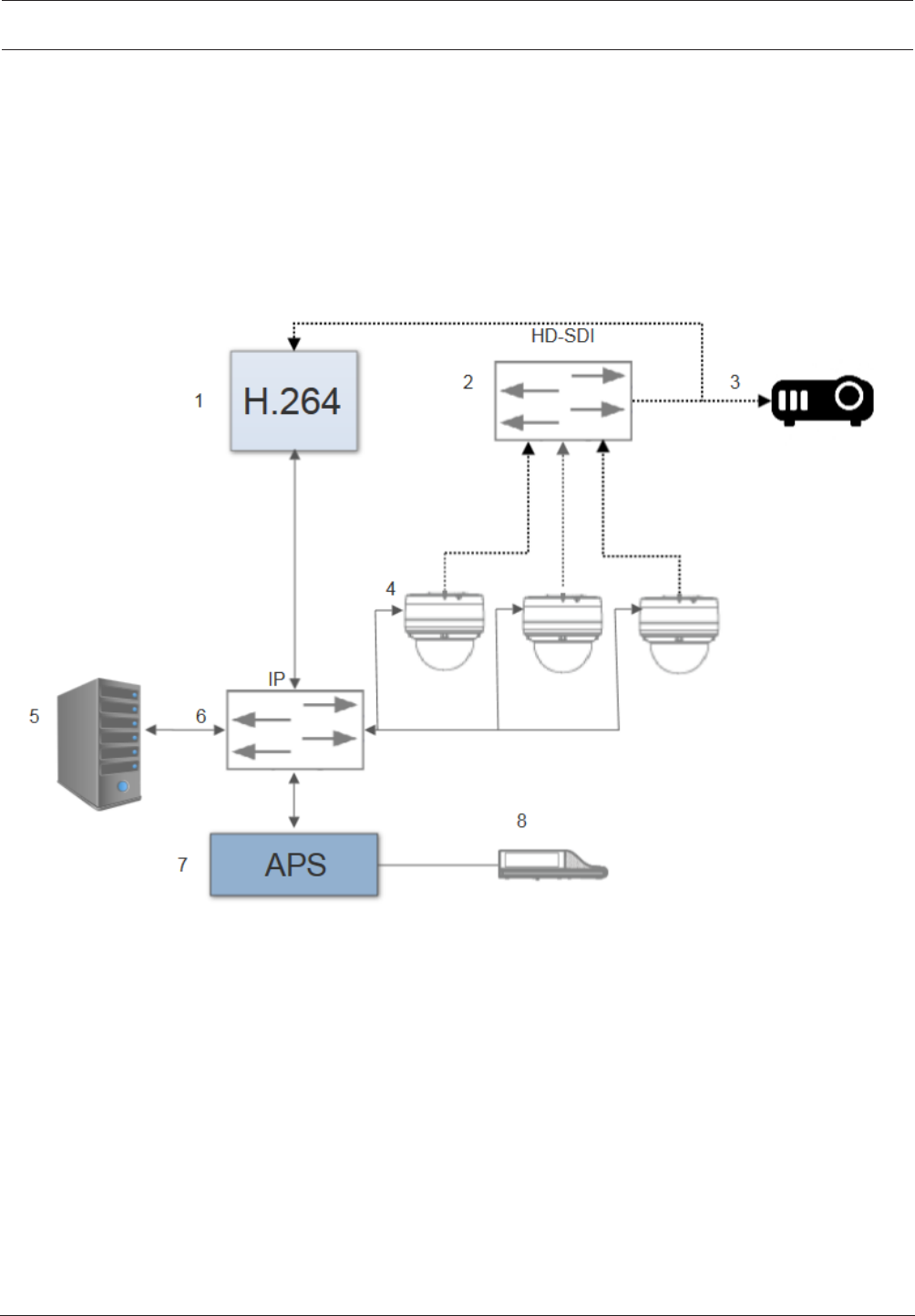
Figure3.2: Typical camera setup
A typical camera setup in a DICENTIS Conference System consists of:
1. H.264 encoder to encode the HD SDI video to H.264
2. HD-SDI switcher
3. Projector
4. Video camera (Onvif Profile-S compatible camera, Sony, Panasonic)
5. System server controller (PC)
6. L3 Ethernet switch
7. Audio processor and powering switch (DCNM-APS / DCNM-APS2)
8. DCNM-MMD2
Cables:
– Dotted line = HD-SDI (coax cable)
– Black with arrow = Ethernet TCP/IP
– Black straight line = DCNM-cable


DICENTIS System installation overview | en 13
Bosch Security Systems B.V. Hardware Installation Manual 2018.09 | V1.8 |
3.2 System extension
The DICENTIS Conference System is scalable from small to medium to large. This section
describes what a small, medium and large system is and what the requirements are for these
systems:
A small DICENTIS Conference System (see Typical system setup, page 10) consists of:
– up to 100 DICENTIS devices.
– all DICENTIS devices in 1 subnet.
– 1 DICENTIS Audio processor and powering switch for the audio processing.
– 1 Server PC which hosts the DICENTIS services.
A medium DICENTIS Conference System consists of:
– up to 450 DICENTIS nodes.
Refer to table X about the node count of DICENTIS equipment.
– all DICENTIS devices in 1 subnet.
– 1 DICENTIS Audio processor and powering switch for the audio processing.
– 1 Server PC which hosts the DICENTIS services.
– 1 ARNI-Standard to increase the size of the system.
A large DICENTIS Conference System consists of:
– up to 750 DICENTIS devices.
– multiple subnets connected by use of a router/L3 switch.
– Each subnet can have up to 450 DICENTIS nodes.
Refer to the following table for the node count of DICENTIS equipment.
– The first subnet has:
- 1 DICENTIS Audio processor and powering switch for the audio processing.
- 1 Server PC which hosts the DICENTIS services.
- 1 ARNI-Enterprise to increase the size of the system.
– All other subnets have 1 ARNI-Standard to increase the size of the system.
Note: There is no DICENTIS Audio processor and powering switch in the other
subnets.
Device Node count
DICENTIS server 0
DICENTIS meeting application 0
DICENTIS Audio processor and powering switch 1
DICENTIS Powering switch 1
DICENTIS multimedia device 2
DICENTIS discussion device 1
DICENTIS discussion device select language 1
DICENTIS discussion device voting 1
DICENTIS discussion device extended 1
DICENTIS Interpreter desk 1
DCNM-IDESKVID Interpreter desk with video 1

14 en | System installation overview DICENTIS
2018.09 | V1.8 | Hardware Installation Manual Bosch Security Systems B.V.
Device Node count
ARNI‑E OMNEO interface 0
ARNI‑S OMNEO interface 0
Tab.3.1: Nodes count of DICENTIS equipment
An ARNI (Audio Routed Network Interface) is used to increase the number of DICENTIS
devices on a single subnet and to connect multiple DICENTIS system subnets. If more than
one subnet is required, two types of an ARNI must be used.
– OMN-ARNIS (ARNI‑S OMNEO interface): The ARNI‑S is required for increasing the system
size above 100 DICENTIS devices. It supports up to 450 DICENTIS nodes in its subnet. It
also acts as a DHCP server in its subnet.
– OMN-ARNI‑E (ARNI‑E OMNEO interface): The ARNI‑E is required for increasing the system
size above 450 DICENTIS nodes. It supports up to 450 DICENTIS nodes in its subnet. It
also acts as a DHCP server in its subnet. It can connect up to 40 subnets, each with an
ARNI‑S.
Defining subnets and subnet masks
A subnet is a logical, visible subdivision of an IP network. The number of DICENTIS devices
that can be in the same subnet depends on the subnet mask.
A standard class C subnet (255.255.255 or /24) can contain 254 IP addresses. Some
DICENTIS devices have 2 IP addresses. For this reason, Bosch advises to use 255.255.252.0
(or /22) as a subnet mask. This allows you to have 1018 IP addresses. The following table lists
the number of IP address per DICENTIS device in a DICENTIS Conference System.
Device IP addresses
DICENTIS server (optional Meeting Application) 1
Client PC running DICENTIS meeting application 1
DICENTIS Audio processor and powering switch 1
DICENTIS Powering switch 1
DICENTIS multimedia device 2
DICENTIS discussion device 1
DICENTIS discussion device select language 1
DICENTIS discussion device voting 1
DICENTIS discussion device extended 2
DICENTIS Interpreter desk 2
DCNM-IDESKVID Interpreter desk with video 3
ARNI‑Enterprise 1
ARNI‑Standard 1
IP camera 1

DICENTIS System installation overview | en 15
Bosch Security Systems B.V. Hardware Installation Manual 2018.09 | V1.8 |
Device IP addresses
SDI video switcher 1
Tab.3.2: Nodes count of DICENTIS equipment
Maximum number of DICENTIS devices in a string:
– The max age timer should be set to 22 when RSTP is used for cable redundancy to
prevent a defective cable or powering switch from influencing the system.
– Each time data hops from one switch to another, the age is increased by one. This timer
can be reached or exceeded, because a daisy chain can be used to loop through the
DICENTIS devices.
– This timer (or restriction) cannot be reached when there is no cable redundancy. This is
because the power limitation will be reached before the max age restriction is reached.
– The timer can be reached when:
– you use cable redundancy,
– the system is incorrectly wired.
16 en | System installation overview DICENTIS
2018.09 | V1.8 | Hardware Installation Manual Bosch Security Systems B.V.
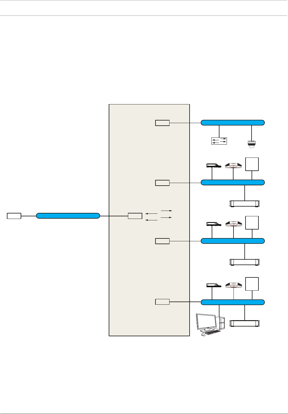
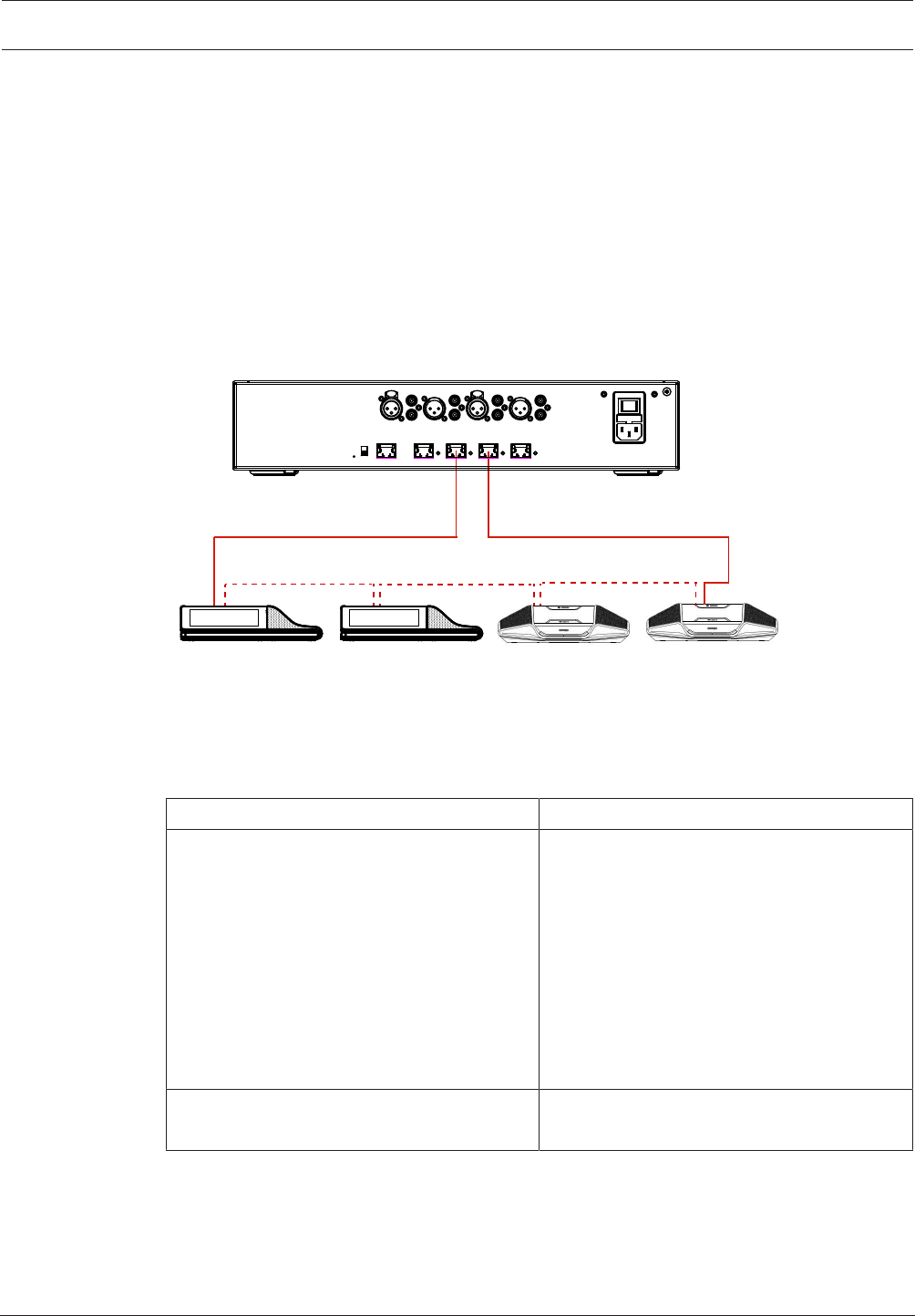
Multi subnet DICENTIS Conference System
The following figure illustrates a typical multi subnet DICENTIS Conference System with a total
of 1200 DICENTIS devices.
– The system is divided over four (4) subnets, where two (2) subnets having a maximum of
400 DICENTIS devices and an OMN-ARNIS are connected.
– The system has one OMN-ARNIS installed in the first subnet with a maximum of 400
DICENTIS devices connected (Note that only one OMN-ARNIS is allowed within a multiple
subnet DICENTIS Conference System).
– Subnet four (4): When using multiple subnets, make sure that all cameras needed to
capture video of the seats are all connected to the same subnet.
192.168.64.x
OMN-ARNI-E
192.168.64.1
VLAN64
192.168.65.254
Ports 1, 2, 3, 4
L3 Switch
VLAN66
192.168.67.254
Ports 5, 6, 7, 8
VLAN74 (internet)
192.168.1.253
Ports 17, 18, 19, 20
VLAN68
192.168.69.254
Ports 9, 10, 11, 12
VLAN70
192.168.71.255
Internal DHPC server
Ports 13, 14, 15, 16
Internet Router
192.168.1.254
DCNM-APS(2)
DCNM server PC
DCNM-PS(2)
DICENTIS devices
Max. 420 nodes
DICENTIS devices
Max. 420 nodes
DICENTIS devices
Max. 420 nodes
DCNM-PS(2)
OMN-ARNI-S
192.168.66.1
OMN-ARNI-S
192.168.68.1
192.168.66.x
192.168.1.x
192.168.68.x
192.168.70.x
12
Figure3.3: Typical DICENTIS Conference System with multiple subnets
–1: External video switcher.
–2: Dome camera.
DICENTIS System installation design and planning | en 17
Bosch Security Systems B.V. Hardware Installation Manual 2018.09 | V1.8 |
4 System installation design and planning
Before you start to install system devices and connect system cabling, you should make a
system design and planning:
– Familiarize yourself with the product and system capabilities.
– Make a cable (connection) plan:
– Calculate the system network cable length.
– Calculate the system power consumption.
– Calculate the required power capacity of the system.
Notice!
The DICENTIS Conference System uses the RSTP protocol when redundant cabling mode is
enabled. If the DICENTIS Conference System needs to be connected with the locally present
network, please consult the local IT department before continuing with the installation
design.
Notice!
Make sure that the cable lengths and power consumptions do not exceed the specifications.
Not doing so will result in malfunctioning at any moment of the DICENTIS Conference System
and products.
4.1 System capabilities
The capability of the DICENTIS Conference System and DICENTIS products depends on:
– The lengths of the system network cables.
– The number of connected devices.
– The system power supply capacity.
Cable length
System network cables (DCNM‑CBxx-I) lengths (2, 5, 10 or 25m) have a direct effect on the
available power supply capacity. The longer the system network cable, the less power supply
capacity is available to drive the connected devices. Therefore, choose the lengths of the
system network cables carefully.
Notice!
Custom network cables must never exceed the maximum Ethernet specification of 100m
(IEEE 802.3ab).
Keep your network hierarchy as flat as possible. This means having as few levels as possible.
It is recommended not to exceed 7 levels. See the following example: 1: 1st level = Root
switch, 2: 2 nd level = switch, 3: 3 rd level = switch.
1
2 2 2 2
3 3 3 3
Figure4.1: Example: Switch-levels

18 en | System installation design and planning DICENTIS
2018.09 | V1.8 | Hardware Installation Manual Bosch Security Systems B.V.
Power supply capacity
The total system network cable length and connected devices determine the required power
supply capacity. The power within the DICENTIS Conference System is supplied by:
– The Audio processor and powering switch and the Powering switch, or
– Off‑the‑shelf PoE Ethernet switches.
Calculation tool
The calculation tool can be used to calculate the total power capacity of the system. This
makes the design and planning of the DICENTIS Conference System easier. The calculation
tool uses the power consumption of the devices and the system network cable lengths to
calculate the needed system power supply capacity.
The calculation tool is on the DVD supplied with the Audio processor and powering switch and
is part of the DICENTIS software DCNM.iso file. The DCNM.iso file can be downloaded from
the Bosch website at: https://licensing.boschsecurity.com/software
DICENTIS System installation design and planning | en 19
Bosch Security Systems B.V. Hardware Installation Manual 2018.09 | V1.8 |
4.2 Hardware requirements
Switches
The following minimum requirements and recommendations apply to switches used in a
DICENTIS:
Requirement Standard Settings
Gbit Ethernet IEEE802.3 Switch latency is maximally 10µSec with Gbit.
Valid for both copper and/or fiber ports.
Packet forwarding in
HW per port
>1.2Mpps
n.a. If SW is responsible for packet switching, this would
result in variable latency which is unacceptable.
Quality of Service
With strict priority
DiffServ To make sure PTP synchronization packets and
audio packets get priority over control packets.
OMNEO uses QoS on IP level to avoid
synchronization and audio problems on busy
networks. Although the system does work without
problems on relatively quiet networks (< 10%
network load) it is important to configure your
network switches correctly.
The used QoS is Differentiated Services or DiffServ,
which is part of the Type of Services field (ToS) in
the IP header. For more details on DiffServ & IP
header, see Wikipedia.
Warning: IEEE802.1p is also used for QoS, but is limited to layer 2. Since OMNEO uses IP
communication, this mechanism is not suitable, so make sure the used equipment uses
DiffServ QoS!
The table below gives an overview of the used DSCP values which need to be configured in
the switch:
Data DSCP dec DSCP hex DSCP Label TOS byte
(hex)
Switch
Priority
queue
PTP sync,
delay req
56 0x38 CS7 0xE0 Highest
PTP follow-
up, delay
response,
audio
46 0x2E EF 0xB8 High
(reserved) 8 0x08 CS1 0x20 Low
Control 0 0x00 Best effort 0x00 None
Warning: Please check thoroughly if your switch’s highest priority queue is label as #1 or e.g.
#8, because this may differ per brand. Unfortunately this is not consistent over the different
brands. Setting it wrong is worse than not having priority.

20 en | System installation design and planning DICENTIS
2018.09 | V1.8 | Hardware Installation Manual Bosch Security Systems B.V.
Switches must be configured to support DiffServ (DSCP) quality of service The switch needs
to have 4 priority queues for the DiffServ mechanism to work.
Warning: Never use VOIP QoS settings!
Requirement Standard Settings
MAC table >1000 n.a. To avoid the switch starts broadcasting unicast
packets because it runs out of space.
Disable EEE IEEE 802.3az Most implementations of EEE cause problems
because of implementation flaws. A good
implementation should work, but does not save
energy since the PTP synchronization avoids this.
Therefore, EEE must always be disabled.
Disable RSTP (when
no cable loops are
used)
Rapid Spanning Tree Protocol (RSTP) is required
when (cable) loops are created for redundancy. When
no loops are created, RSTP needs to be disabled for
optimal operation. When enabled, it can cause slow
connections to the switch.
Possibility to create
VLANS
n.a. VLAN separation is recommended instead of IGMP
snooping, because most switches are unable to
handle the multicast changes in the system. Filtering
multicast data may be necessary for some devices,
such as 100 Mb devices (Sony cameras, TVOne, AMX,
and others).
IGMPv3 IGMPv2
snooping in
hardware
IGMPv3 or IGMPv2 snooping. To optimize bandwidth
usage, IGMP snooping can be used. This is useful in
systems with >10 multicast streams, although not
absolutely required. Sufficient performance for
handling a large number of IGMP query responses,
depends on the number of (directly or indirectly)
connected devices to that switch. Hardware support
for IGMP snooping is strongly recommended.
Requirements when
Redundant wiring is
used
Standard Settings
RSTP IEEE802.1D-20
04
RSTP is used to allow the creation of loops for
redundancy. The switch must support changing the
following parameters to the listed values:
– Hello_Time = 9 seconds
– Forwarding_delay = 30 seconds
– Max_age = 22 seconds
Diagnostics
Link Layer discovery IEEE 802.1AB For network diagnoses using Network Docent.
SNMP SNMP For network diagnoses using Network Docent.

DICENTIS System installation design and planning | en 21
Bosch Security Systems B.V. Hardware Installation Manual 2018.09 | V1.8 |
Routers
The following minimal requirements apply to routers:
– 1Gbit or higher Ethernet ports.
– Supports PIM‑DM or Bidirectional PIM.
– Performs IP routing in hardware (i.e. a ‘layer 3 switch’) to minimize the routing delay.
– Packet forwarding rate > 1,000,000 packets per second per port (e.g. 8Mpps for an
8‑port router).
– Non-blocking backplane per switching port, i.e. 2Gbit per port (e.g. 16Gbps for an 8‑port
router).
– MAC address table of at least 1000 addresses per directly connected subnet.
22 en | System installation design and planning DICENTIS
2018.09 | V1.8 | Hardware Installation Manual Bosch Security Systems B.V.
4.3 Power supply capacity calculation plan
How to start
Notice!
It is advisable to use the power calculation tool. The calculation tool is on the DVD supplied
with the Audio processor and powering switch and is also part of the DICENTIS software
DCNM.iso file, which can be downloaded from the Bosch website at: https://
licensing.boschsecurity.com/software
Decide how to supply power to the DICENTIS devices:
– Using the Audio processor and powering switch and one or more Powering switches.
– Using one or more PoE Ethernet switches.
If you want to use PoE Ethernet switches, continue with chapter Calculation using PoE
switches, page 24.
See also
– Calculation using DCNM-APS(2) or DCNM-PS(2), page 22
– Installation material and tools, page 31
4.3.1 Calculation using DCNM-APS(2) or DCNM-PS(2)
Notice!
If you want to use customized cables, or a more accurate power supply capacity calculation
plan is needed, you should use the power calculation tool.
To calculate the total power supply capacity:
1. Count all DICENTIS devices.
2. Know the exact location where the devices are installed.
3. Count each system network cable of the same length.
Device type Power consumption (Watts)
DCNM-D 3.10
DCNM-DSL 3.60
DCNM-DVT 3.70
DCNM-DE 5.00
DCNM-MMD 11.30
DCNM-MMD2 12.00
DCNM-IDESK 15.00
DCNM-IDESKVID 18.00
DCNM‑CB02-I 1.19
DCNM‑CB05-I 2.43
DCNM‑CB10-I 4.50
DICENTIS System installation design and planning | en 23
Bosch Security Systems B.V. Hardware Installation Manual 2018.09 | V1.8 |
Device type Power consumption (Watts)
DCNM‑CB25-I 10.71
Tab.4.3: Power consumption (Watts)
Ordering number Cable lengths
m ft
DCNM-CB02-I 2 6.56
DCNM-CB05-I 5 16.40
DCNM-CB10-I 10 32.81
DCNM-CB25-I 25 82.02
Tab.4.4: Cable types and lengths
Rear view
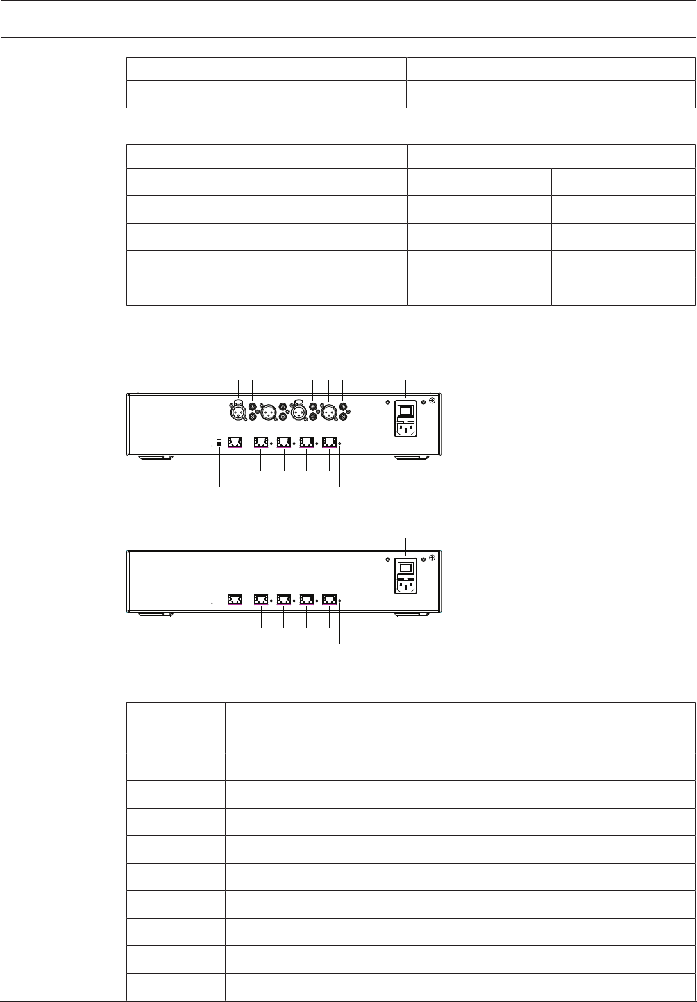
10 12 13 15 17 19
11 14 16 18 20
1 2 3 4 5 6 7 8 9
Figure4.2: Audio processor and powering switch
10 12 13 15 17
14 16 18
19
20
9
Figure4.3: Powering switch
Item Description
1, 5 XLR line outputs 1 and 2.
2, 6 RCA line outputs 1 and 2.
3, 7 XLR line inputs 1 and 2.
4, 8 RCA line inputs 1 and 2.
9 Mains inlet, mains switch and fuse holder.
10 Reset button.
11 Ground switch (grounded or floating).
12 Socket 1 without power.
13 Socket 2 low power.
15, 17, 19 Socket 3, 4, 5 high power.
24 en | System installation design and planning DICENTIS
2018.09 | V1.8 | Hardware Installation Manual Bosch Security Systems B.V.
Item Description
14, 16, 18, 20 Overload LED for sockets 2‑5:
Green: Power OK.
Red: Overload. Remove cable and wait a few seconds for the system to
reset the overload.
Network and Power connector Max. power output (W) Max. devices
Socket 1 (12) No power capacity ---
Socket 2 (13) 15 1
Socket 3 (15) 144 40
Socket 4 (17) 144 40
Socket 5 (19) 144 40
Tab.4.5: Power supply capacity DCNM‑APS(2) / DCNM‑PS(2)
Calculation examples
The following example gives you an indication of the maximum load to each socket of an Audio
processor and powering switch or Powering switch.
–Socket 2: 50m cable + DCNM-MMD2 = 12W1
–Socket 3: 10m cable + DCNM-MMD2 + 9x (2m cable + DCNM-MMD2)
= (4.5 + 12) + 9x(1.19 + 12) = 135.21W2.
–Socket 4: 10m cable + DCNM-D + 19x (2m cable +DCNM-D)
= (4.5 + 3.1) + 19x(1.19 + 3.1) = 89.11W2.
–Socket 5: 10m cable + DCNM-DE + 19x (2m cable + DCNM-DE)
= (4.5 + 5) + 19x(1.19 + 5) = 127.11W2.
1
For socket 2, the cable power consumption of the cable does not need to be counted if only one device is connected to this output.
2
The shortest redundant cable does not need to be counted.
4.3.2 Calculation using PoE switches
Select one or more PoE Ethernet switches to supply power to the DICENTIS devices. Each
DICENTIS device must be connected to an individual PoE enabled output of an Ethernet
switch.
Notice!
Some PoE Ethernet switches can only supply power to a limited number of ports. Others can
supply power to every port, but the total power the Ethernet switch can supply is limited.
Please consult the documentation of the PoE Ethernet switch used.
Notice!
Using PoE, DICENTIS devices cannot be daisy‑chained connected. Using PoE does not provide
redundant cabling.
DICENTIS System installation design and planning | en 25
Bosch Security Systems B.V. Hardware Installation Manual 2018.09 | V1.8 |
2
1
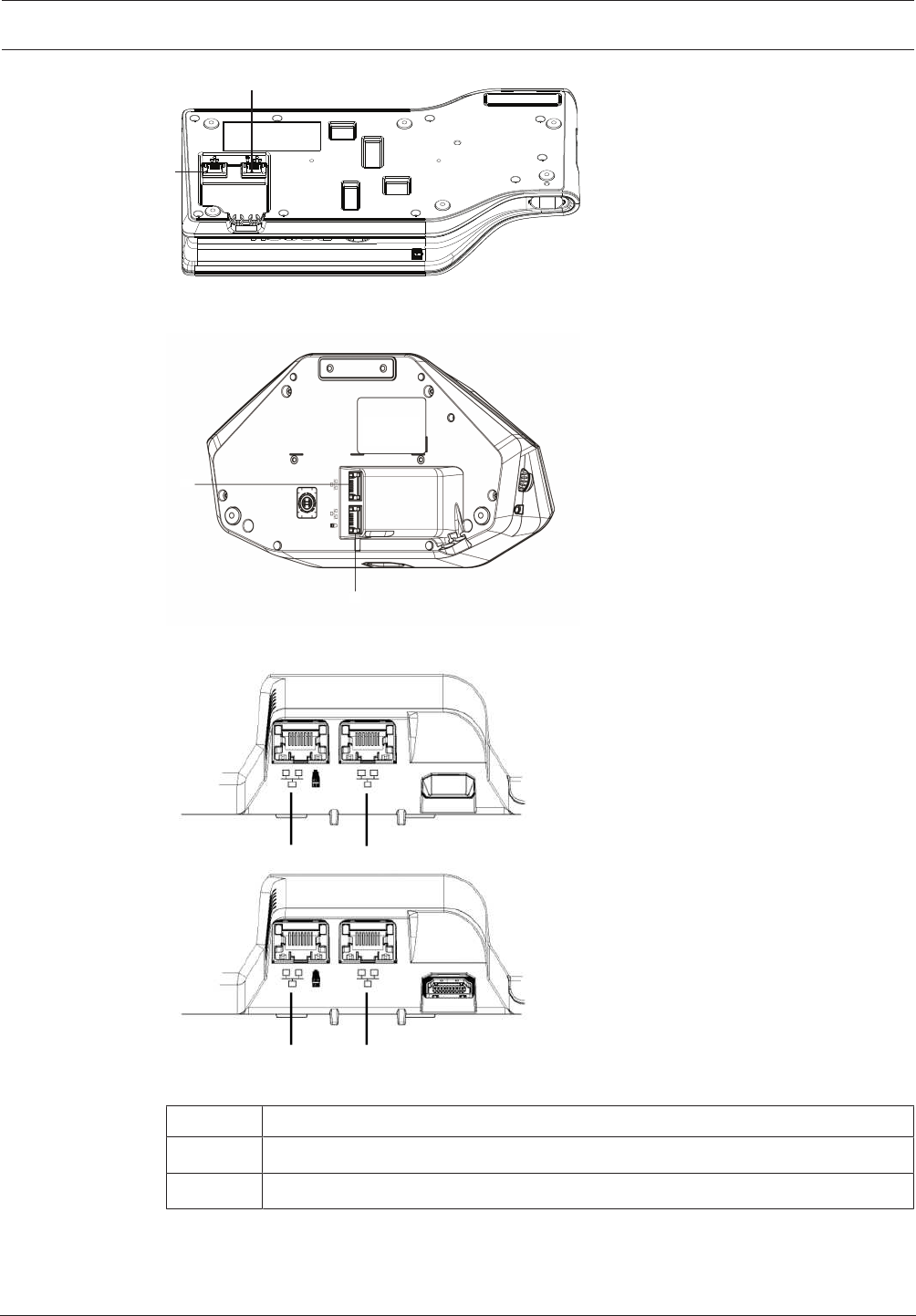
Figure4.4: Bottom view DICENTIS devices (DCNM-MMD / DCNM-MMD2)
2
1
Figure4.5: Bottom view DICENTIS devices (DCNM-D / DCNM-DVT / DCNM-DSL / DCNM-DE)
2 1
2 1
DCNM-IDESK
DCNM-IDESKVID
Figure4.6: Bottom view DICENTIS Interpreter devices (DCNM-IDESK / DCNM-IDESKVID)
Item Description
1 Network connector
2 Network / PoE connector
26 en | System installation design and planning DICENTIS
2018.09 | V1.8 | Hardware Installation Manual Bosch Security Systems B.V.
4.4 Redundancy options
DICENTIS Conference Systems can be created with network redundancy. This ensures that the
system will continue to work if:
– a network cable is defective or accidentally disconnected.
– one of the components fails.
Different levels of redundancy can be created in the system depending on:
– the type of unit used in the system (DCNM-APS / DCNM-PS or DCNM-APS2 / DCNM-PS2)
– the number of redundant components used in the system.
– the amount of redundant network cabling.
The following sections explain the redundancy options that can be used when designing your
DICENTIS Conference System. Each option can be combined in the DICENTIS Conference
System, providing you observe the redundant cabling limitations. Refer to:
–Redundant cabling for DCNM‑APS/DCNM‑PS units, page 27.
–Redundant cabling for DCNM-APS2/DCNM-PS2 units, page 28.
–Redundant server PC, page 30.
Notice!
Rapid Spanning Tree Protocol (RSTP) must be enabled in the DICENTIS Conference System
for these redundancy options to work correctly.
Notice!
Follow these steps when setting up redundancy options for your system:
1. First, set up your system without cable redundancy and RSTP configuration in the system
and DICENTIS.
2. Secondly, configure RSTP in the switches and DICENTIS.
3. Thirdly, enable the cable loops.
DICENTIS System installation design and planning | en 27
Bosch Security Systems B.V. Hardware Installation Manual 2018.09 | V1.8 |
4.4.1 Redundant cabling for DCNM‑APS/DCNM‑PS units
This section describes how to create redundant cabling for DCNM-APS or DCNM-PS units. The
maximum number of Ethernet devices in the loop (including the root switch) is 22. In a system
with no Ethernet switch(es), the APS is the root switch.
The total number of devices allowed in a loop depends on:
– The type of device connected in the loop (for example, DCNM-MMD2 devices consume
more power than DCNM-DE devices).
– The length of the loop (cable also consumes power).
The figure shows how to calculate the number of devices in the loop. The red line shows the
largest loop. The # sign shows the way the devices are counted.
In the example below up to 21 (22 - 1 = 21) discussion devices can be connected.
1
2
33
#1
#2 #22
Figure4.7: DICENTIS devices connected with redundant cabling to the same DCNM-APS / DCNM-PS type
unit
1: DCNM-APS or DCNM-PS.
2: DICENTIS devices.
3: DICENTIS cabling (redundant loop).
Cabling possibilities (DCNM‑APS/DCNM‑PS) Limitations/requirements
Connect the DICENTIS devices in a daisy
chain configuration from a high power socket
on a DCNM-PS or DCNM-APS to another high
power socket on the same DCNM-PS or
DCNM-APS.
The redundancy is for cable only. If the
DCNM-PS or DCNM-APS fails, all DICENTIS
devices connected to that unit will also fail.
If a single DICENTIS device fails, the other
DICENTIS devices in the daisy chain will
continue to work.
To enable redundancy, Rapid Spanning Tree
Protocol (RSTP) must be enabled.
You can use any of the high power sockets (3,
4, or 5) to create the daisy chain.
The redundant loop must be connected to
the same DCNM-APS or same DCNM-PS.
See also
– Power supply capacity calculation plan, page 22
28 en | System installation design and planning DICENTIS
2018.09 | V1.8 | Hardware Installation Manual Bosch Security Systems B.V.
4.4.2 Redundant cabling for DCNM-APS2/DCNM-PS2 units
This section describes how to create redundant cabling for DCNM-APS2 / DCNM-PS2 type
units. The maximum number of Ethernet devices in the largest possible loop (including the
root switch) is 22. In a system with no Ethernet switch(es), the APS is the root switch.
The total number of devices allowed in a loop depends on:
– The type of device connected in the loop (for example, DCNM-MMD2 devices consume
more power than DCNM-DE devices).
– The length of the loop (cable also consumes power).
The figure shows how to calculate the number of devices in the loop. The red line shows the
largest loop. The # sign shows the way the devices are counted.
In the example below up to 19 (22 - 3 = 19) discussion devices can be connected.
#1
#2 #22
#3 #21
1
34
55
5 5
5 5
44
2
Figure4.8: DICENTIS discussion devices connected with redundant cabling between DCNM-PS2 / DCNM-
APS2 type units
1: DICENTIS system/client PC.
2: Network switch (with optional redundant power supply)
3: DCNM-APS2
4: DCNM-PS2
5: DICENTIS cabling (redundant loop)
Cabling possibilities (DCNM-APS2/DCNM-
PS2)
Limitations/requirements
Create a redundant loop by connecting the
DICENTIS devices in a daisy chain
configuration from a high power socket on a
DCNM-PS2 / DCNM-APS2 to a high power
socket on another DCNM-PS2.
The redundant loop between two DCNM-PS2
units is for power and signal. If one of the
DCNM-PS2 units fails, the other DCNM-PS2
unit will supply power and signal to the
DICENTIS devices in the daisy chain.
The redundancy is for cable only. If the
DCNM-PS or DCNM-APS fails, all DICENTIS
devices connected to that unit will also fail.
To enable redundancy:
– Rapid Spanning Tree Protocol (RSTP)
must be enabled in the DICENTIS
Conference System.
– a network switch with redundant power
supply, should be connected to the
DCNM-PS2 / DCNM-APS2 units, as
shown in the previous figure.
DICENTIS System installation design and planning | en 29
Bosch Security Systems B.V. Hardware Installation Manual 2018.09 | V1.8 |
Cabling possibilities (DCNM-APS2/DCNM-
PS2)
Limitations/requirements
You can use any of the high power sockets (3,
4, or 5) on either of the DCNM-PS2 units to
create the daisy chain/redundant loop.
For example, high power socket 3 on one unit
can be connected to high power socket 4 on
another unit.
Note: The redundant loop must be connected
to another DCNM-PS2 type unit. You cannot
use DCNM-PS / DCNM-APS type units to
create redundant loops for power.
You can create a redundant loop for signal
only, by connecting the DICENTIS devices in a
daisy chain configuration to the same DCNM-
PS2 or DCNM-APS2, although this is not
recommended.
The DCNM-PS2 unit is designed to reduce
cost of ownership, for example, by allowing a
maximum of three redundant loops to be
connected between two DCNM-PS2 units.
The redundant loop will function in the same
way as a DCNM-PS / DCNM-APS type unit.
Refer to Redundant cabling for DCNM‑APS/
DCNM‑PS units, page 27.
Notice!
Rapid Spanning Tree Protocol (RSTP) must be enabled in the DICENTIS Conference System
for these redundancy options to work correctly.
See also
– Power supply capacity calculation plan, page 22
30 en | System installation design and planning DICENTIS
2018.09 | V1.8 | Hardware Installation Manual Bosch Security Systems B.V.
4.4.3 Redundant server PC
System availability can be improved by connecting a redundant DICENTIS server PC and the
associated components and cables to the DICENTIS Conference System. The maximum
number of Ethernet devices in the largest possible loop (including the root switch) is 22.
The total number of devices allowed in a loop depends on:
– The type of device connected in the loop (for example, DCNM-MMD2 devices consume
more power than DCNM-DE devices).
– The length of the loop (cable also consumes power).
The figure shows how to calculate the number of devices in the loop. The red line shows the
largest loop. The # sign shows the way the devices are counted.
In the example below up to 17 (22 - 5 = 17) devices can be connected.
#4 #20
#2
#3 #21
#22
#1
1
1
44
5
5
5
3
22
Figure4.9: Redundant DICENTIS server PC with redundant components and cables
1: DICENTIS system/client PC
2: Network switch (with optional redundant power supply)
3: DCNM-APS2
4: DCNM-PS2
5: DICENTIS cabling (redundant loop)
For this option to work the DICENTIS Conference System has to be run in combination with
EverRun Enterprise software from Stratus Technologies. For more information, refer to the
Stratus Technologies website.
Other options that can be used for guaranteeing the reliability of the DICENTIS Conference
System include:
– Remote SQL servers.
DICENTIS Installation material and tools | en 31
Bosch Security Systems B.V. Hardware Installation Manual 2018.09 | V1.8 |
5 Installation material and tools
This section describes installation material such as cables, connectors and tools.
Recommedations
– Always use manufacturer specified installation products, materials and tools.
– In general, use different cable ducts for the system network cables, audio cables and
mains supply cables.
– In public areas where people can touch or move above the connectors and cables, use
metal protection covers.
!
Warning!
Do not exceed the bend limitations of system network cables (DCNM‑CBxxx):
The minimum bend radius of the system network cable is a 35mm radius.
5.1 DICENTIS System Cable Assemblies
The DICENTIS System Cable Assemblies, terminated with connectors on both ends, are
available in different lengths and are used to connect DICENTIS devices to each other. The
cable consists of a low smoke zero halogen solid core.
Ordering number Cable lengths
m ft
DCNM-CB02-I 2 6.56
DCNM-CB05-I 5 16.40
DCNM-CB10-I 10 32.81
DCNM-CB25-I 25 82.02
Tab.5.6: Cable types and lengths
Figure5.1: DCNM-CBxx-I cable and connector view
32 en | Installation material and tools DICENTIS
2018.09 | V1.8 | Hardware Installation Manual Bosch Security Systems B.V.
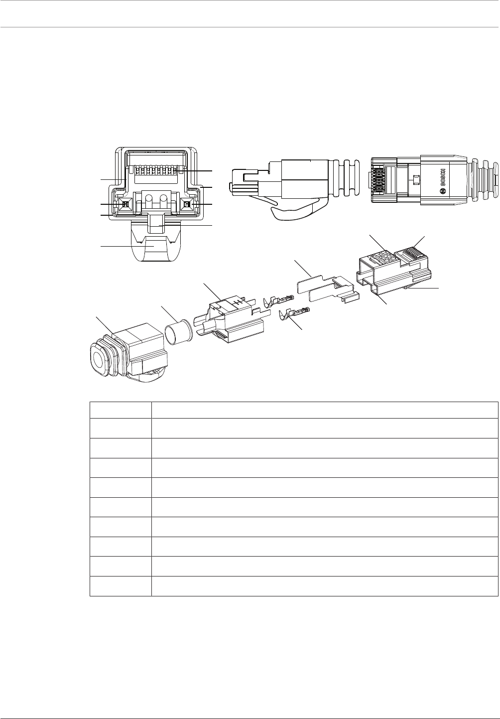
5.2 DCNM-CBCON Connectors for DICENTIS cable
The connectors are used to make your own system network cables or to replace a connector.
The cable can be used for solid core cable (DCNM-CB02-I, DCNM-CB05-I, DCNM-CB10-I,
DCNM-CB25-I, DCNM-CB250-I, DCNM-CB250), as well as stranded core cable (DCNM-CB02,
DCNM-CB05, DCNMCB10, DCNM-CB25, DCNM-CB02B, DCNM-CB05B, DCNM-CB10B, DCNM-
CB25B, DCNM-CB250B).
1
2
3
5
79
8
6
4
4
3
1
5
6
7
9
8
1
2
3
5
79
8
6
4
4
3
1
5
6
7
9
8
Figure5.2: DCNM-CBCON Front and exploded view
Item Description
1 Strain relief boot
2 Ferrule
3 Plug connector shield
4 Power contacts (Qty: 2)
5 Load bar
6 Power contact cavity (2 places)
7 Housing
8 Locking latch
9 Signal contact cavity (8 Places)
See also
– DICENTIS System Cable Assemblies, page 31
– DCNM-CB250-I System Installation Cable, page 34
– DCNM-CBTK System Network Cable Toolkit, page 33
DICENTIS Installation material and tools | en 33
Bosch Security Systems B.V. Hardware Installation Manual 2018.09 | V1.8 |
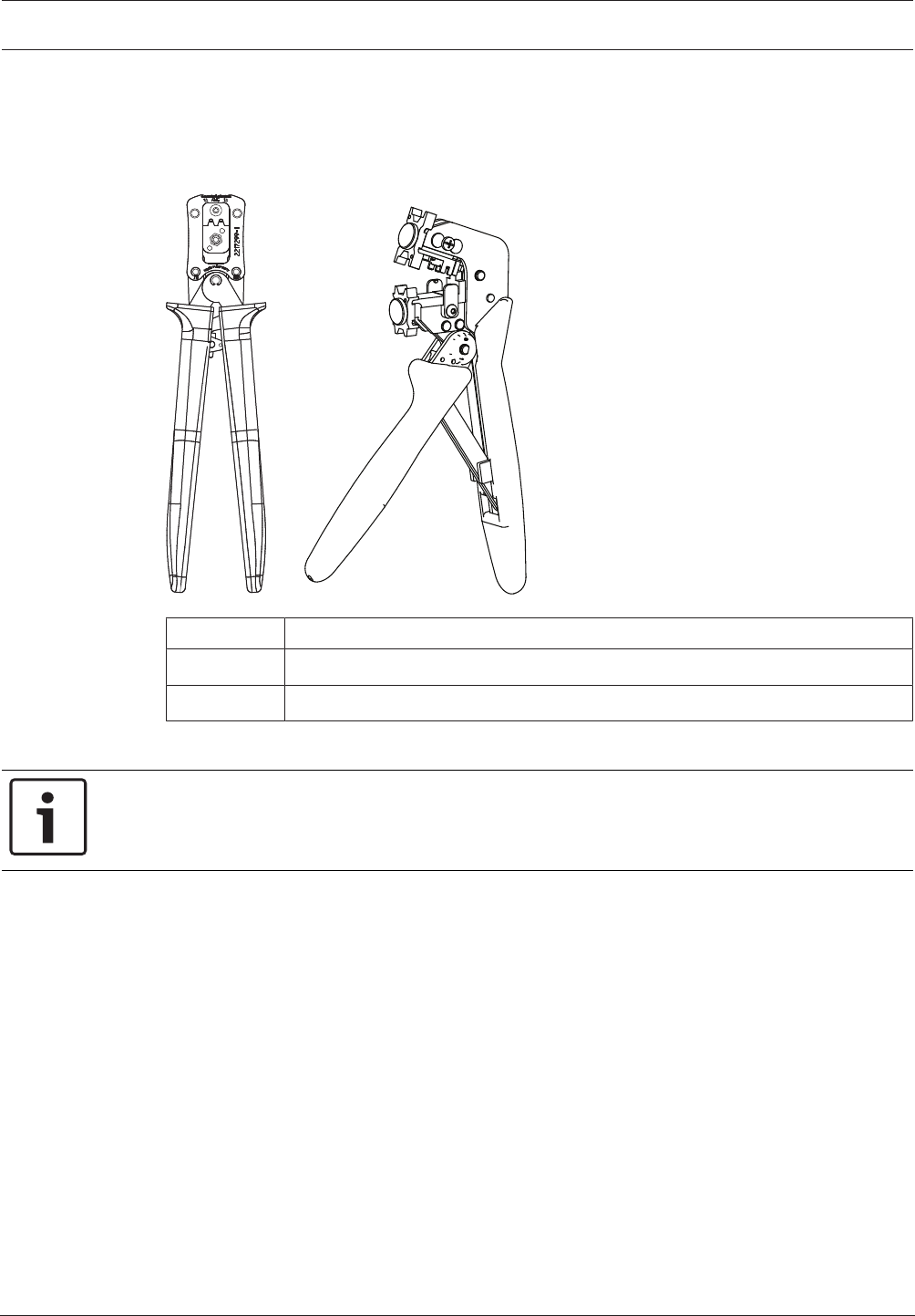
5.3 DCNM-CBTK System Network Cable Toolkit
The system network cable toolkit is used to connect the DCNM-CBCON Connectors for
DICENTIS cable, page 32 to the DCNM-CB250-I System Installation Cable, page 34 or DICENTIS
System Cable Assemblies, page 31.
21
Item Description
1 Power wiring tool.
2 Signal wiring tool.
Tab.5.7: Toolkit content
Notice!
Please consult the “custom length for system network cables” section on the DVD, which can
be downloaded at: https://licensing.boschsecurity.com/software
34 en | Installation material and tools DICENTIS
2018.09 | V1.8 | Hardware Installation Manual Bosch Security Systems B.V.
5.4 DCNM-CB250-I System Installation Cable
The system installation cable, without connectors, is available in a length of 250 meters and is
used for making your own system network cable. Refer also to the sections DCNM-CBCON
Connectors for DICENTIS cable, page 32 and DCNM-CBTK System Network Cable Toolkit, page
33.
Notice!
The maximum system network cable length is: 100m / 328,9ft.
Notice!
Please consult the “custom length for system network cables” section on the DVD, which can
be downloaded at: https://licensing.boschsecurity.com/software
See also
– DCNM-CBCON Connectors for DICENTIS cable, page 32
DICENTIS Installation material and tools | en 35
Bosch Security Systems B.V. Hardware Installation Manual 2018.09 | V1.8 |
5.5 DCNM-CBCPLR Cable couplers
Cable couplers can be used:
– to extend cables,
– in a floor pod as break-out box,
– as an interface between DICENTIS cable and “standard” CAT-5E cable combined with a
separate power cable,
– to insert power locally to the participant devices,
– to switch the system on by using two cable couplers and a switch.
Cable couplers are delivered in a box that contains 6 cable couplers. They can be used for all
types of DICENTIS cables.
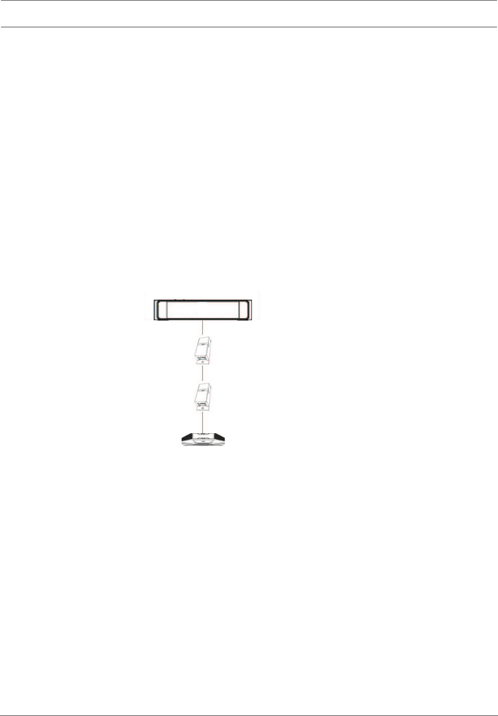
5.5.1 Using a cable coupler to extend a cable
The DICENTIS Cable coupler can be used to extend cables, as it allows you to connect
DICENTIS Cable assemblies together. This way, it is possible to connect, for example, three 25
m (DCNM-CB25-I) cables together to form a 75 m cable.
Note:
– The cable length is not allowed to exceed 100 m.
– No more than 2 cable couplers can be used in one trunk.
DCNM-(A)PS
DCNM-(A)PS
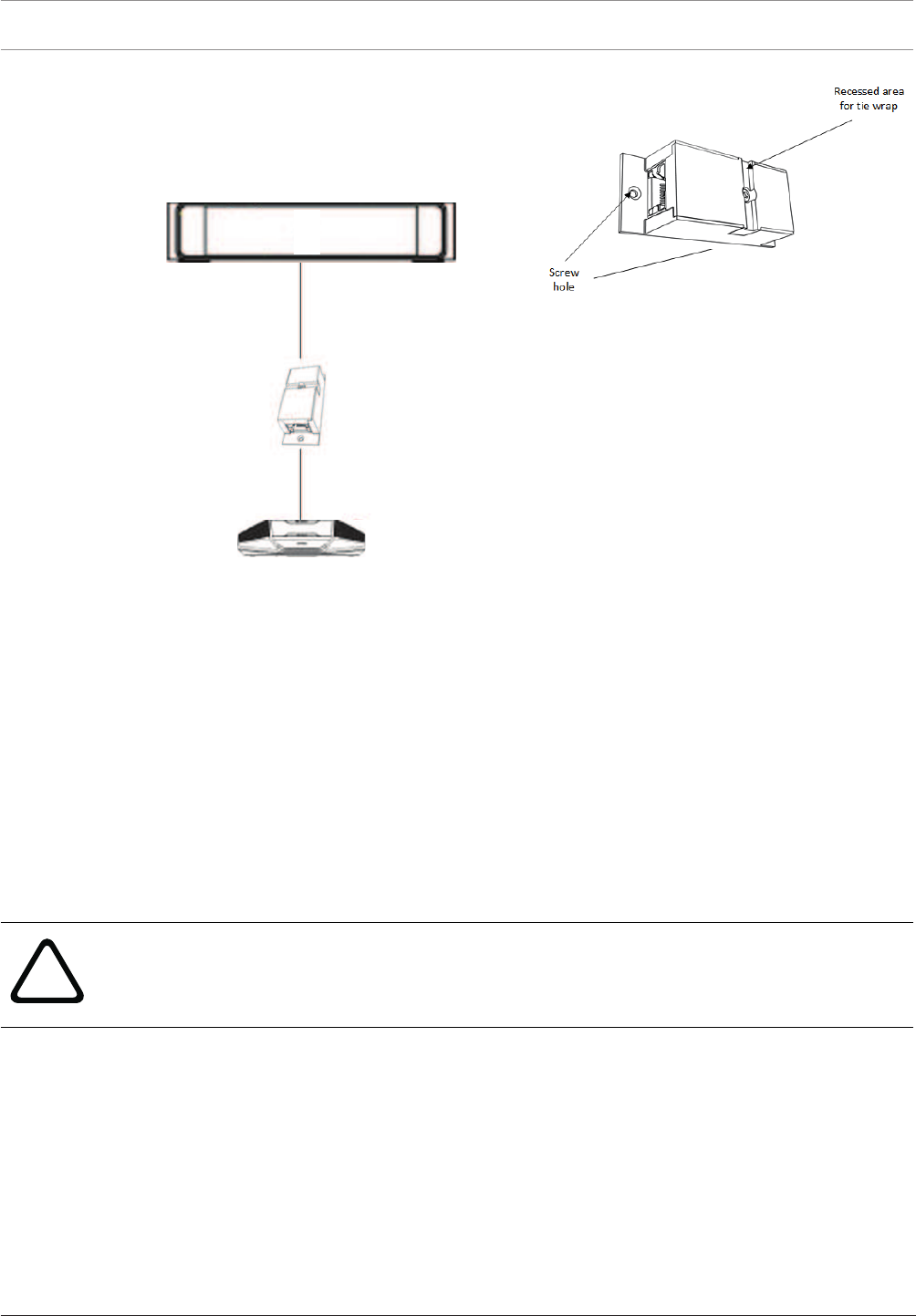
5.5.2 Using a cable coupler as a break-out box
The DICENTIS Cable coupler can be used in a floor pod as a break-out box, for example, if you
want to connect temporary devices like a rostrum microphone. The cable coupler can be
fixated using the screw holes (2.5 mm) or via a tie wrap through the recessed area.
Note:
– The cable length is not allowed to exceed 100 m.
– No more than 2 cable couplers can be used in one trunk.
36 en | Installation material and tools DICENTIS
2018.09 | V1.8 | Hardware Installation Manual Bosch Security Systems B.V.
DCNM-(A)PS
Installation in a floor pod as break-out box
5.5.3 Using a cable coupler as an interface between different types of cable
The cable coupler can be used as an interface between DICENTIS cable and “standard”
CAT-5E cable, optionally combined with a separate power cable. This can be used, for
example, when standard CAT-5E cabling coming from the technical room has to be connected
with DICENTIS cable in the conference room.
To set this up:
1. Open the housing of the cable coupler.
2. Connect the power cables to the screw terminals + and -.
3. Remove the break-out of the housing to guide the power cables through.
4. Create a tension release.
!
Warning!
Risk of electric shock. Exposed power cables are a potential hazard. Make sure all power
cables are securely fastened by fixing them with a tie wrap on the inside of the box (see
drawing ‘Creating a tension relief’).
5. Close the housing and fix the screw with torque 0.4Nm.
Note:
– The cable length is not allowed to exceed 100 m.
– No more than 2 cable couplers can be used in one trunk.