Bosch Security Systems DCNMWDE DICENTIS WIRELESS DEVICE EXTENDED User Manual DICENTIS Wireless IM

Bosch Security System BV DICENTIS WIRELESS DEVICE EXTENDED DICENTIS Wireless IM

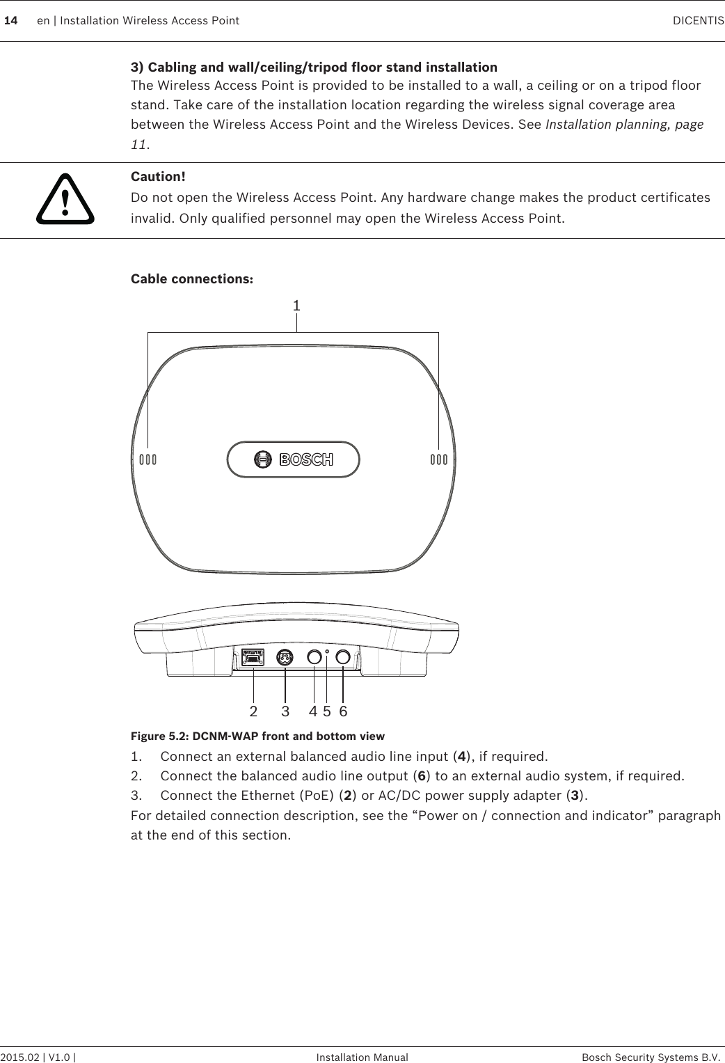
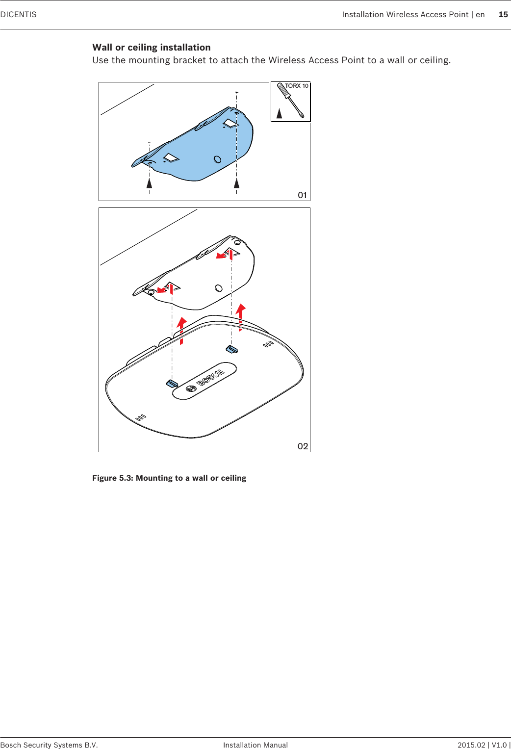
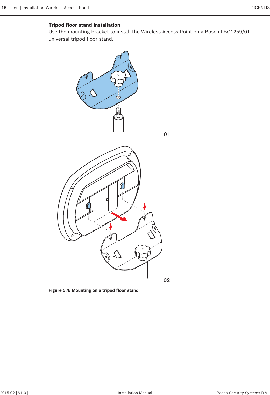
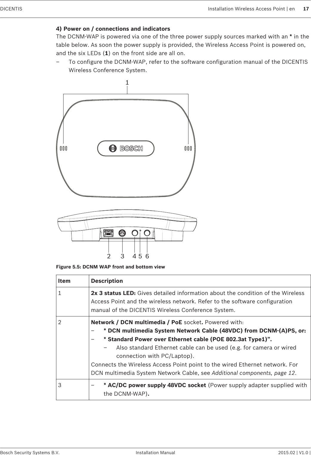
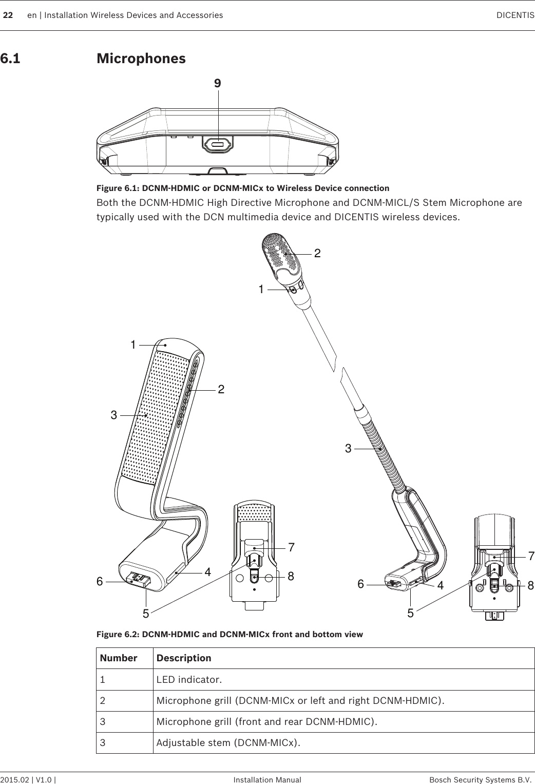
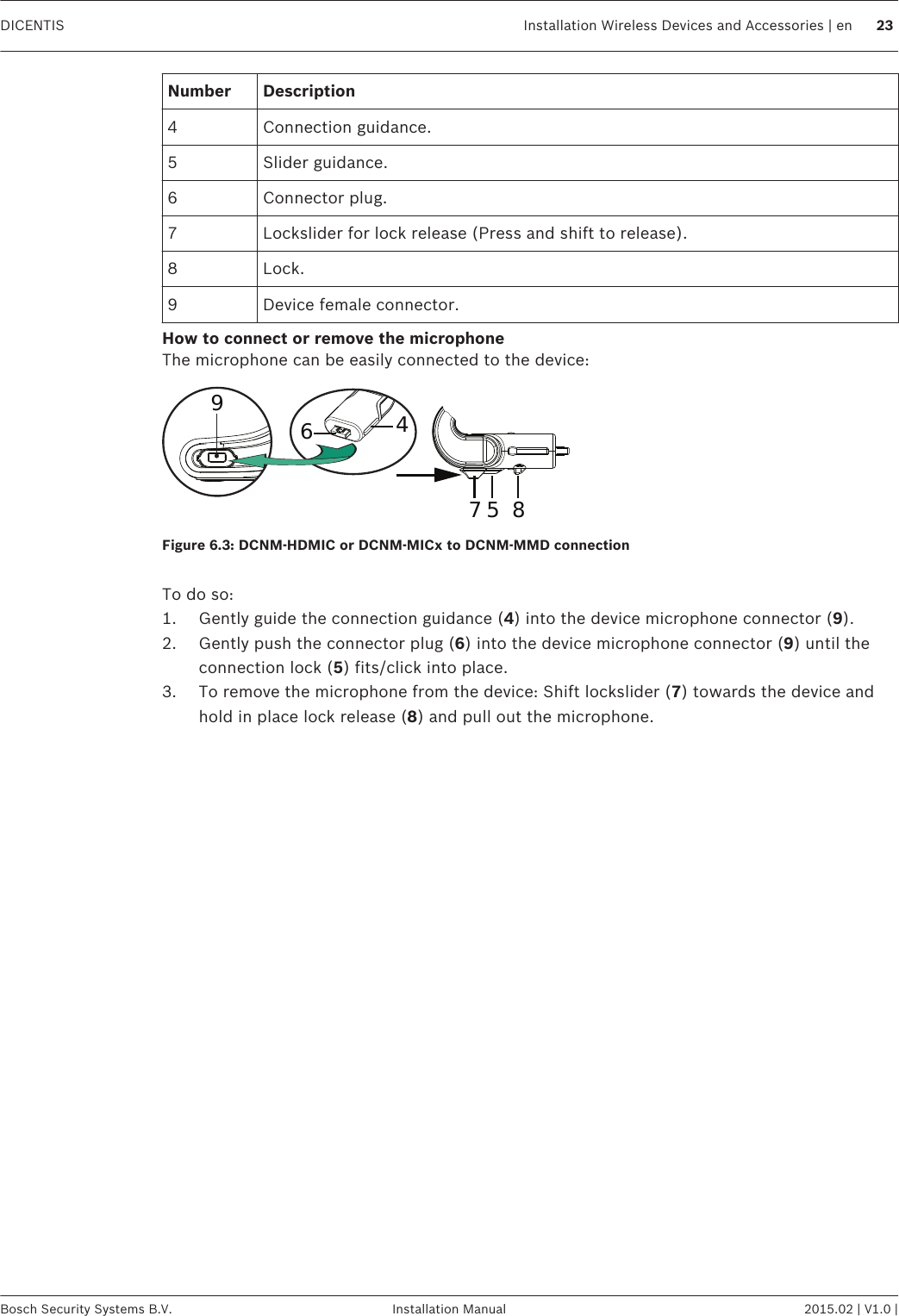
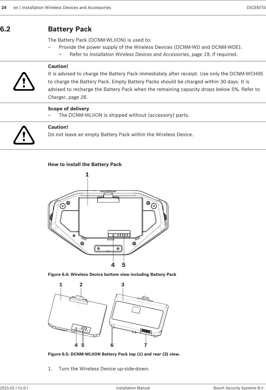
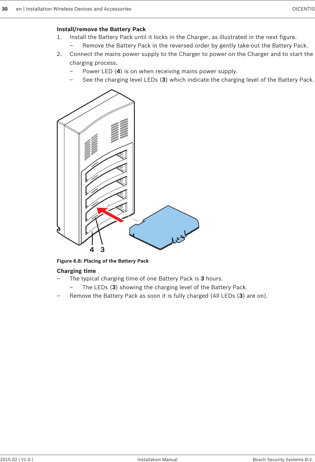
07b_User Manual_DICENTIS_Wireless_IM_V1.0_enUS

      DICENTISWireless Conference System  en Installation Manual
Table of contents1Safety 41.1 Battery Pack 41.2 Statements for FCC & Industry Canada 42About this manual 62.1 Intended audience 62.2 Alerts and notice signs 62.3 Copyright and disclaimer 62.4 Document history 73System overview 83.1 Extended system requirements 104Installation planning 114.1 Unpacking 124.2 Additional components 125Installation Wireless Access Point 136Installation Wireless Devices and Accessories 196.1 Microphones 226.2 Battery Pack 246.3 Charger 267System power on and configuration 318Maintenance 328.1 Cleaning 328.2 Inspect components 328.3 Service 329Technical data 339.1 Wireless Access Point (DCNM-WAP) 339.2 Wireless Devices (DCNM-WD and DCNM-WDE) 359.3 Battery Pack (DCNM-WLIION) 379.4 Charger (DCNM-WCH05) 389.5 High Directive Microphone (DCNM-HDMIC) 399.6 Stem Microphones (DCNM-MICx) 40DICENTIS Table of Contents | en 3Bosch Security Systems B.V. Installation Manual 2015.02 | V1.0 |
SafetyPrior to installing or operating products, always read the Important Safety Instructions whichare available as a separate multilingual document: Important Safety Instructions (Safety_ML).These instructions are supplied together with all equipment that can be connected to themains supply.Old electrical and electronic appliancesElectrical or electronic devices that are no longer serviceable must be collected separately andsent for environmentally compatible recycling (in accordance with the European WasteElectrical and Electronic Equipment Directive).To dispose of old electrical or electronic devices, you should use the return and collectionsystems put in place in the country concerned.Battery PackPlease take notice of the safety instructions as printed on the label of the DCNM-WLIIONBattery Pack.Statements for FCC & Industry CanadaThis Class A digital apparatus complies with Canadian ICES-003. Cet appareil numérique de laclasse A est conforme à la norme NMB‑003 du Canada.This equipment has been tested and found to comply with the limits for a Class A digitaldevice, pursuant to Part 15 of the FCC Rules. These limits are designed to provide reasonableprotection against harmful interference when the equipment is operated in a commercialenvironment. This equipment generates, uses, and can radiate radio frequency energy and, ifnot installed and used in accordance with the instruction manual, may cause harmfulinterference to radio communications. Operation of this equipment in a residential area islikely to cause harmful interference in which case the user will be required to correct theinterference at their own expense. The Wireless Discussion Devices and the Wireless Access Point comply with Part 15 of theFCC Rules and with RSS‑210 of Industry Canada. Operation is subject to the following twoconditions:1. This device may not cause harmful interference.2. This device must accept any interference received, including interference that may causeundesired operation. Le présent appareil est conforme aux CNR d'Industrie Canada applicables aux appareils radioexempts de licence. L'exploitation est autorisée aux deux conditions suivantes:1. l'appareil ne doit pas produire de brouillage, et.2. l'utilisateur de l'appareil doit accepter tout brouillage radioélectrique subi, même si lebrouillage est susceptible d'en compromettre le fonctionnement.Notice!Changes or modifications made to this equipment, not expressly approved by Bosch SecuritySystems B.V. may void the FCC authorization to operate this equipment.11.11.24en | Safety DICENTIS2015.02 | V1.0 | Installation Manual Bosch Security Systems B.V.
Notice!The Wireless Discussion Devices and the Wireless Access Point comply with FCC radiationexposure limits set forth for an uncontrolled environment. The Wireless Discussion Devicesand the Wireless Access Point should be installed and operated with minimum distance of20 cm to your body. DICENTIS Safety | en 5Bosch Security Systems B.V. Installation Manual 2015.02 | V1.0 |
About this manualThe purpose of this manual is to provide information required for installing the DICENTISWireless Conference System.– Please read this manual carefully before installing any of the products of the DICENTISWireless Conference System.– Retain all documentation supplied with the products for future reference.– This installation manual is available as a digital document in the Adobe PortableDocument Format (PDF).– For more information, refer to the product related information on:www.boschsecurity.com > Country of your choice > Conference Systems > DICENTISWireless Conference SystemIntended audienceThis hardware installation manual is intended for installers of a DICENTIS Wireless ConferenceSystem.Alerts and notice signsFour types of signs can be used in this manual. The type is closely related to the effect thatmay be caused if it is not observed. These signs - from least severe effect to most severeeffect - are:Notice!Containing additional information. Usually, not observing a ‘notice’ does not result in damageto the equipment or personal injuries.!Caution!The equipment or the property can be damaged, or persons can be lightly injured if the alertis not observed.!Warning!The equipment or the property can be seriously damaged, or persons can be severely injuredif the alert is not observed.Danger!Not observing the alert can lead to severe injuries or death.Copyright and disclaimerAll rights reserved. No part of this document may be reproduced or transmitted in any form byany means, electronic, mechanical, photocopying, recording, or otherwise, without the priorwritten permission of the publisher. For information on getting permission for reprints andexcerpts, contact Bosch Security Systems B.V..The content and illustrations are subject to change without prior notice.22.12.22.36en | About this manual DICENTIS2015.02 | V1.0 | Installation Manual Bosch Security Systems B.V.
Document historyRelease date Documentation version Reason2015.02 V1.0 1st edition.2.4DICENTIS About this manual | en 7Bosch Security Systems B.V. Installation Manual 2015.02 | V1.0 |
System overviewThe DICENTIS Wireless Conference System is a “standalone” IP based system. It usesWiFi IEEE 802.11n for wireless distribution and processing of audio and data signals. A typical DICENTIS Wireless Conference System (see the following figure and numbering onthe next page) consists of a Wireless Access Point (1) (including power supply adapter)Wireless Devices (4 + 5) (including Battery Pack and microphone) a tablet device (7) foroperational use, PC/laptop (8) for licensing and operational use (The PC/laptop is onlyneeded temporarily for licensing and updates of the system software), and Battery PackCharger (6).8967145923Figure 3.1: Typical DICENTIS Wireless Conference System A typical extended DICENTIS Wireless Conference System (see the following figure andnumbering on the next page) has an additional Ethernet network/video switch (10) and HDConference Dome (11).869712345991011Figure 3.2: Typical extended DICENTIS Wireless Conference System 38en | System overview DICENTIS2015.02 | V1.0 | Installation Manual Bosch Security Systems B.V.
1. The Wireless Access Point (DCNM-WAP) is the central device of the DICENTIS WirelessConference System. The Wireless Access Point is used to:– Host a web interface for licensing, configuring and controlling the system.– Control the system audio and routing of the audio from and to the Wireless Devices.– Environment wireless channel scanning. The best available wireless channel will bechosen for the system.– Camera control. Controls the optional connected switch (10) and cameras (11).2. AC/DC power supply adapter (supplied with the DCNM-WAP).3. (Optional connections) Audio line input and audio line output.4. Wireless Device (DCNM-WD) used as a single-use, dual-use or chairperson WirelessDevice, including Battery Pack and microphone (Both to be ordered separately).– Participants can use the Wireless Device to participate in a discussion.5. Wireless Device Extended (DCNM-WDE) used as a single-use, dual-use or chairpersonWireless Device, extended with Near Field Communication (NFC) reader for useridentification and 4.3” capacitive touch screen, including Battery Pack and microphone(Both to be ordered separately).– Participants can use the Wireless Device Extended to participate in a discussion.6. Charger (DCNM-WCH05) used to charge the Battery Packs of the Wireless Devices.7. Tablet device:– Used to configure and control the system via the website hosted on the DCNM-WAP.8. PC/Laptop:– Temporary used to license and update the systems firmware.9. Optional DCN multimedia System Network Cable:– Is used for powering the DCNM-WAP via the DCNM-APS and for connection to theEthernet.10. Optional Ethernet network switch:– Is used for powering (Power over Ethernet) of the DCNM-WAP and routing of thesystem data via Ethernet.11. Optional HD Conference Dome:– Captures the video of a participant speaking. DICENTIS System overview | en 9Bosch Security Systems B.V. Installation Manual 2015.02 | V1.0 |
Extended system requirementsThe following requirements are valid if you want to extend your system with a network switchor cameras:–Network switch and camera installation instructions are not part of this installationmanual; please consult the product related documentation of the supplier.– Notice that a DHCP server is needed for both the Wireless Access Point and the cameras.CamerasTypical, the Bosch HD Conference Dome is used. Refer to product related information on:www.boschsecurity.com > Country of your choice > Conference Systems > DICENTIS WirelessConference System > HD cameras and accessories.3.110 en | System overview DICENTIS2015.02 | V1.0 | Installation Manual Bosch Security Systems B.V.
Installation planningMake sure you have all components for installing and connecting the DICENTIS WirelessConference System (see System overview, page 8).– Familiarize yourself with the products capabilities of the DICENTIS Wireless ConferenceSystem (see System overview, page 8 and the paragraphs Control capacity and Coveragearea in this section.– Use only Bosch specified installation materials and tools (see Additional components, page12).1. Decide if, and which type of, cabling is required. See System overview, page 8.2. Decide on how to power the Wireless Access Point (DCNM-WAP). See System overview,page 8:– Via the AC/DC power supply adapter (supplied with the DCNM-WAP). Or:– Via Power over Ethernet (PoE). Or:– Via Ethernet switch. Or:– DCN multimedia (Audio) Powering Switch.3. Provide a mains power supply connections nearby the equipment which requires mainspower supply.4. Decide on how to power the other devices used in the system (i.e. Ethernet switch,cameras etc.). See System overview, page 8:– Via their own (mains) power supply provision. Or:– Via Power over Ethernet (PoE), if possible.5. Decide on how, and where, to install the Wireless Access Point (DCNM-WAP). SeeInstallation Wireless Access Point, page 13:– Wall, ceiling or tripod floor stand.– For a maximum WiFi coverage area, the DCNM-WAP can be placed on a centrallocation in the room.6. Decide where, and how to place, the Wireless Devices (DCNM-WD and/or DCNM-WDE).See Installation Wireless Devices and Accessories, page 19.Control capacity– The Wireless Access Point (DCNM-WAP) can control a maximum number of 120 WirelessDevices in the DICENTIS Wireless Conference System network.– Only one DCNM-WAP at the time can control the system.Coverage area– All Wireless Devices need to be in the WiFi coverage area of the DCNM-WAP.– The DCNM-WAP has a typical WiFi coverage area of 30 m by 30 m.802.11n specificationThe DICENTIS Wireless Conference System network is based on the 802.11n specification forWiFi technology. Devices that comply to the 802.11n specification operate in frequency bandsbetween 2.4000 and 2.4835 GHz and 5.180 and 5.700 GHz.Notice!Although the system operates on frequencies which are license free world wide, you must beaware of country specific limitations and follow them. 4 DICENTIS Installation planning | en 11Bosch Security Systems B.V. Installation Manual 2015.02 | V1.0 |
UnpackingThis equipment should be unpacked and handled with care. If an item appears to be damaged,notify the shipper immediately. If any items are missing, notify your Bosch representative.The original packaging is the safest container in which to transport products and can be usedto return products for service if necessary.Additional componentsThe following additional components can be used with the DICENTIS Wireless ConferenceSystem, as required:DCN multimedia System Network Cables – Required in case you like to power the DCNM-WAP via the DCNM‑(A)PS. For cable types (DCNM‑CBxx) refer to the datasheet on:www.boschsecurity.com > Country of your choice > Conference Systems > DICENTIS WirelessConference SystemRCA cables – RCA cables are required if you want to connect optional audio equipment to theaudio line input and/or audio line output of the Wireless Access Point (DCNM-WAP), such asmicrophones and a sound reinforcement system.CAT5e cables - Required if you want to connect a PC/Laptop to the Wireless Access Point(DCNM-WAP) for running the web interface and connecting a switch and HD ConferenceDomes.4.14.212 en | Installation planning DICENTIS2015.02 | V1.0 | Installation Manual Bosch Security Systems B.V.
Installation Wireless Access PointUse the following steps to install the Wireless Access Point (DCNM-WAP).1. Make sure all equipment is available as described in 1) Scope of delivery.2. Optional set the “Brand logo” in the correct orientation.3. Connect the cabling and install the Wireless Access Point to the wall/ceiling or tripodfloor stand.4. Power on the Wireless Access Point.1) Scope of deliveryThe Wireless Access Point (DCNM-WAP) is shipped with the following parts:Quantity Components1 DCNM-WAP Wireless Access Point1 AC/DC power supply adapter. Including: AC plug‑AU, AC plug‑UK, ACplug‑EU, AC plug‑US1 Mounting bracket1 DVD with manuals and software1 Safety instructions2) Brand logoThe orientation of the logo could be changed.0201TORX 10Figure 5.1: Change logo orientation 5DICENTIS Installation Wireless Access Point | en 13Bosch Security Systems B.V. Installation Manual 2015.02 | V1.0 |
3) Cabling and wall/ceiling/tripod floor stand installationThe Wireless Access Point is provided to be installed to a wall, a ceiling or on a tripod floorstand. Take care of the installation location regarding the wireless signal coverage areabetween the Wireless Access Point and the Wireless Devices. See Installation planning, page11.!Caution!Do not open the Wireless Access Point. Any hardware change makes the product certificatesinvalid. Only qualified personnel may open the Wireless Access Point. Cable connections:12 3 4 5 6Figure 5.2: DCNM‑WAP front and bottom view1. Connect an external balanced audio line input (4), if required.2. Connect the balanced audio line output (6) to an external audio system, if required.3. Connect the Ethernet (PoE) (2) or AC/DC power supply adapter (3).For detailed connection description, see the “Power on / connection and indicator” paragraphat the end of this section.  14 en | Installation Wireless Access Point DICENTIS2015.02 | V1.0 | Installation Manual Bosch Security Systems B.V.
Wall or ceiling installationUse the mounting bracket to attach the Wireless Access Point to a wall or ceiling.0201TORX 10Figure 5.3: Mounting to a wall or ceiling DICENTIS Installation Wireless Access Point | en 15Bosch Security Systems B.V. Installation Manual 2015.02 | V1.0 |
Tripod floor stand installationUse the mounting bracket to install the Wireless Access Point on a Bosch LBC1259/01universal tripod floor stand.0201Figure 5.4: Mounting on a tripod floor stand 16 en | Installation Wireless Access Point DICENTIS2015.02 | V1.0 | Installation Manual Bosch Security Systems B.V.
4) Power on / connections and indicatorsThe DCNM-WAP is powered via one of the three power supply sources marked with an * in thetable below. As soon the power supply is provided, the Wireless Access Point is powered on,and the six LEDs (1) on the front side are all on.– To configure the DCNM-WAP, refer to the software configuration manual of the DICENTISWireless Conference System.12 3 4 5 6Figure 5.5: DCNM WAP front and bottom viewItem Description12x 3 status LED: Gives detailed information about the condition of the WirelessAccess Point and the wireless network. Refer to the software configurationmanual of the DICENTIS Wireless Conference System.2Network / DCN multimedia / PoE socket. Powered with:–* DCN multimedia System Network Cable (48VDC) from DCNM‑(A)PS, or:–* Standard Power over Ethernet cable (POE 802.3at Type1)”.– Also standard Ethernet cable can be used (e.g. for camera or wiredconnection with PC/Laptop).Connects the Wireless Access Point point to the wired Ethernet network. ForDCN multimedia System Network Cable, see Additional components, page 12.3 – * AC/DC power supply 48VDC socket (Power supply adapter supplied withthe DCNM-WAP).DICENTIS Installation Wireless Access Point | en 17Bosch Security Systems B.V. Installation Manual 2015.02 | V1.0 |
Item Description4Balanced audio line output socket: Connection to a public address system,audio mixers or to a voice logging system for audio registration of all spokenconference proceedings. Use standard line output cabling. 6.3mm (1/4") jackswith the following pinning:Tip: Live (+)Ring: Return (-)Sleeve: Shield6Balanced audio line input socket: Connection from audio source. Use standardline output cabling. 6.3 mm (1/4") jacks with the following pinning:Tip: Live (+)Ring: Return (-)Sleeve: Shield5Reset‑to‑default button: Sets the DCNM-WAP to factory default values. Pressand hold for at least 8 seconds to set all settings to factory default.18 en | Installation Wireless Access Point DICENTIS2015.02 | V1.0 | Installation Manual Bosch Security Systems B.V.
Installation Wireless Devices and AccessoriesThe Wireless Devices are used to add participants to a discussion. See System overview, page8, if required.Scope of delivery– The DCNM-WD and DCNM-WDE are shipped without (accessory) parts.InstallationThe Wireless Devices are free‑standing (table-top use). No mechanical installation, other thanthe accessories as described below, is required.!Caution!If a Wireless Device Extended is moved from a warm and humid environment to a coldenvironment there is a possibility that some condensation can form on the display. To preventthis from happening, make sure each Wireless Device Extended is given sufficient time toacclimatize. 1 2 311416 18175 6 7 8 9 1091012 131415DCNM-WDE and DCNM-WD top, rear and base view!Caution!Do not open the Wireless Device. Any hardware change makes the product certificatesinvalid. Only qualified personnel may open the Wireless Devices.Installation of accessoriesFollow below steps to install the required accessories to, and placing of, the Wireless Devices.These steps are a summary:1. Check that all equipment is available.2. For your reference, see the Wireless Device figure and table in this section.6  DICENTIS Installation Wireless Devices and Accessories | en 19Bosch Security Systems B.V. Installation Manual 2015.02 | V1.0 |
3. Install the Battery Pack (15) in each Wireless Device to be used. Refer to Battery Pack ,page 24.4. Attach the microphones to the Wireless Devices (11). Refer to Microphones, page 22.5. Place the Wireless Devices in the coverage area of the Wireless Access Point (DCNM-WAP). See Installation planning, page 11, if required.Connection, indicators and controlsThe following table gives an overview of the Wireless Device items and functionality (Refer tothe numbers in the previous figure).Connection and configuration of the Wireless Devices within the system is done via DCNM-WAP. Refer to the software configuration manual of the DICENTIS Wireless ConferenceSystem.Item Description1 Near Field Communication (NFC) reader for user identification (DCNM-WDEonly). Used to identify (logon) the participant with an NFC ID‑card or smartphone device with NFC functionality.2 4.3” capacitive touch screen (DCNM-WDE only).3 Loudspeaker.4 + 5 Combined button, depending on software configuration:–chairperson priority button (4). Or,– single-use device mute button (4). Or,– dual-use device microphone request button (5).6 LED (lightguide) microphone request button (5).7 Microphone request button (single-use, chairperson or dual-use mode).8 LED (lightguide) microphone request button (7).9 Headphone volume control.10 3.5 mm stereo jack for headphone.11 Microphone (input) connector.12 Red battery‑low LED indicator. The LED is flashing when the Battery Pack of theWireless Device is empty within 1 hour. Charging the Battery Pack is advised.See Battery Pack , page 24.and Charger, page 26.13 Yellow out‑of‑range LED indicator. The LED is on when the Wireless Device is not(yet) connected with the Wireless Access Point (DCNM-WAP). Move the WirelessDevice within the coverage area of the DCNM-WAP. The LED is flashing when theWireless Device is trying to make a connection with the Wireless Access Point(DCNM-WAP. See Installation planning, page 11.14 (DCNM-WLIION) Battery Pack locking clip. See Battery Pack , page 24.15 (DCNM-WLIION) Battery Pack. See Battery Pack , page 24.16 De‑init button. When push (>2 seconds), the subscription between the WirelessDevice and Wireless Access Point is removed.20 en | Installation Wireless Devices and Accessories DICENTIS2015.02 | V1.0 | Installation Manual Bosch Security Systems B.V.
Item Description17 (DCNM-WLIION) Battery Pack capacity test button. See Battery Pack , page 24.18 (DCNM-WLIION) Battery Pack capacity LED (5x) indicators. See Battery Pack ,page 24. DICENTIS Installation Wireless Devices and Accessories | en 21Bosch Security Systems B.V. Installation Manual 2015.02 | V1.0 |
Microphones9Figure 6.1: DCNM‑HDMIC or DCNM‑MICx to Wireless Device connectionBoth the DCNM‑HDMIC High Directive Microphone and DCNM-MICL/S Stem Microphone aretypically used with the DCN multimedia device and DICENTIS wireless devices.3647125836471258Figure 6.2: DCNM‑HDMIC and DCNM‑MICx front and bottom viewNumber Description1 LED indicator.2 Microphone grill (DCNM‑MICx or left and right DCNM‑HDMIC).3 Microphone grill (front and rear DCNM‑HDMIC).3 Adjustable stem (DCNM‑MICx).6.122 en | Installation Wireless Devices and Accessories DICENTIS2015.02 | V1.0 | Installation Manual Bosch Security Systems B.V.
Number Description4 Connection guidance.5 Slider guidance.6 Connector plug.7 Lockslider for lock release (Press and shift to release).8 Lock.9 Device female connector.How to connect or remove the microphoneThe microphone can be easily connected to the device:964857Figure 6.3: DCNM‑HDMIC or DCNM‑MICx to DCNM‑MMD connection To do so:1. Gently guide the connection guidance (4) into the device microphone connector (9).2. Gently push the connector plug (6) into the device microphone connector (9) until theconnection lock (5) fits/click into place.3. To remove the microphone from the device: Shift lockslider (7) towards the device andhold in place lock release (8) and pull out the microphone. DICENTIS Installation Wireless Devices and Accessories | en 23Bosch Security Systems B.V. Installation Manual 2015.02 | V1.0 |
Battery Pack The Battery Pack (DCNM-WLIION) is used to:– Provide the power supply of the Wireless Devices (DCNM-WD and DCNM-WDE).– Refer to Installation Wireless Devices and Accessories, page 19, if required.!Caution!It is advised to charge the Battery Pack immediately after receipt. Use only the DCNM-WCH05to charge the Battery Pack. Empty Battery Packs should be charged within 30 days. It isadvised to recharge the Battery Pack when the remaining capacity drops below 5%. Refer toCharger, page 26.Scope of delivery–The DCNM-WLIION is shipped without (accessory) parts.!Caution!Do not leave an empty Battery Pack within the Wireless Device. How to install the Battery Pack541Figure 6.4: Wireless Device bottom view including Battery Pack176542 3Figure 6.5: DCNM-WLIION Battery Pack top (1) and rear (3) view. 1. Turn the Wireless Device up‑side‑down.6.2  24 en | Installation Wireless Devices and Accessories DICENTIS2015.02 | V1.0 | Installation Manual Bosch Security Systems B.V.
2. Turn the Battery Pack to top view (1) and hook the securing nocks (6) in the WirelessDevice battery compartment.3. Gently push down the Battery Pack until it locks (2) into the Wireless Device Battery Packcompartment.How to remove the Battery Pack1. Turn the Wireless Device up‑side‑down.2. Remove the Battery Pack in reverse order by push‑and‑hold the locking clip (2) and gentlypushing up the Battery Pack.3. Take out the Battery Pack. Connections and indicatorsThe following table gives an overview of the Battery Pack connections and indicators (refer tothe numbers in the previous figure in this section).Item Description1Top view.2Locking clip mechanism: Locks the Battery Pack in the Wireless Device.3Rear view.4 Battery Pack capacity/condition test button: Pushing the button lights 0 to 5capacity LED indicators, depending on the capacity time left (5).5 Green Battery Pack capacity LED indicators (5x): Showing the capacity/condition of the Battery Pack. From left to right (5‑1), typical each LED indicatesa capacity time in hours left:– LED 5: 18‑20– LED 4: 13‑18– LED 3: 8‑13– LED 2: 3‑8– LED 1: <3NOTE: The accuracy of the Battery Pack remaining capacity is +/- 20%.6Securing nock (3x). Secures the Battery Pack in the Wireless Device.7Power supply and charging connector. DICENTIS Installation Wireless Devices and Accessories | en 25Bosch Security Systems B.V. Installation Manual 2015.02 | V1.0 |
ChargerThe Charger (DCNM-WCH05) is used for (and can be used for connection to IT powerdistribution systems):– Charging the Battery Pack (DCNM-WLIION).– One Charger can charge a maximum of 5 Battery Packs at the same time.Scope of delivery– The DCNM-WCH05 is shipped with the following parts:– 1x Mains power cable.– 1x Loop‑through mains power cable.– 1x Mounting bracket.– 1x Safety instructions.41 2 3 5 6Figure 6.6: Charger DCNM-WCH05Item Description1Ventilation grilles: Do not obstruct the ventilation grilles. The Charger mustremain within the specified temperature range. See Charger (DCNM-WCH05),page 38.2Battery Pack container (5x): Each container could hold a Battery Pack (DCNM-WLIION).3Charging level LEDs: Shows the charging level of the Battery Pack: From left toright (5‑1), typical each LED indicates a capacity time in hours (left):– LED 5: 18‑20– LED 4: 13‑18– LED 3: 8‑13– LED 2: 3‑8– LED 1: <3NOTE: The accuracy of the Battery Pack remaining capacity is +/- 20%.NOTE: It can take up to 1 minute before the first LED is lit.6.326 en | Installation Wireless Devices and Accessories DICENTIS2015.02 | V1.0 | Installation Manual Bosch Security Systems B.V.
Item Description4Power on/off LED: Is on when the power cable is connected to Charger and theother end is connected to the mains power supply.5Mains power supply socket/inlet. The maximum current handling of the inlet is10A. Therefore there is a limitation of the number of loop‑through Chargers. Fordetails, see the Mains power connection / loop‑through paragraph in thissection.6Mains power supply loop‑through socket: The loop‑through mains socket allowsa maximum number of Chargers to be connected in series to share from thesame mains power supply outlet. For details, see the Mains power connection /loop‑through paragraph in this section. InstallationDanger!Do not open the charger. Electrical discharges from the charger can kill you. !Warning!This is a class A product. In a domestic environment this product may cause radiointerference in which case the user may be required to take adequate measures. !Caution!Do not obstruct the ventilation grilles. A blockage of the ventilation grilles can cause a risk offire and malfunction/defect of the Charger and Battery Pack.     DICENTIS Installation Wireless Devices and Accessories | en 27Bosch Security Systems B.V. Installation Manual 2015.02 | V1.0 |
The Charger can be free‑standing or fixed installed in more permanent installations (i.e. to awall), using the mounting bracket.020301TORX 10TORX 10Figure 6.7: Installation to a wall 28 en | Installation Wireless Devices and Accessories DICENTIS2015.02 | V1.0 | Installation Manual Bosch Security Systems B.V.
When installing more than one Charger next to each other, be sure that:–The vertical distance between two brackets is at least 340 mm (refer to d1 in the nextfigure).– The horizontal distance between two brackets is at least 195 mm (refer to d2 in the nextfigure).d2d1Mains power supply connection / loop‑through1. Connect a locally approved mains power cord to the Charger mains power supply socket/inlet (5).2. With the loop‑through mains power supply socket (6), you can loop‑through chargers:– If the mains power supply is 100‑127 V(AC), 50/60 Hz, a maximum of 2 chargers canbe looped‑through.– If the mains power supply is 220‑240 V(AC), 50/60 Hz, a maximum of 5 chargers canbe looped‑through. DICENTIS Installation Wireless Devices and Accessories | en 29Bosch Security Systems B.V. Installation Manual 2015.02 | V1.0 |
Install/remove the Battery Pack1. Install the Battery Pack until it locks in the Charger, as illustrated in the next figure.– Remove the Battery Pack in the reversed order by gently take‑out the Battery Pack.2. Connect the mains power supply to the Charger to power on the Charger and to start thecharging process.– Power LED (4) is on when receiving mains power supply.– See the charging level LEDs (3) which indicate the charging level of the Battery Pack.34Figure 6.8: Placing of the Battery PackCharging time– The typical charging time of one Battery Pack is 3 hours.– The LEDs (3) showing the charging level of the Battery Pack.– Remove the Battery Pack as soon it is fully charged (All LEDs (3) are on).30 en | Installation Wireless Devices and Accessories DICENTIS2015.02 | V1.0 | Installation Manual Bosch Security Systems B.V.
System power on and configurationConsult the software configuration manual of the DICENTIS Wireless Conference System forpower on and configuration details of the Wireless Access Point and Wireless Devices.– For documentation, refer to the DICENTIS Wireless Conference System product relatedinformation on: www.boschsecurity.com > Country of your choice > Conference Systems > DICENTISWireless Conference System7DICENTIS System power on and configuration | en 31Bosch Security Systems B.V. Installation Manual 2015.02 | V1.0 |
MaintenanceThe DICENTIS Wireless Conference System requires minimum maintenance. To ensure fortrouble‑free operation, clean and inspect the system components on a regular basis:Cleaning!Caution!Do not use alcohol, ammonia, petroleum solvents or abrasive cleaners to clean the systemcomponents.1. Clean the Wireless Devices with a soft cloth moistened very slightly with a weak soap andwater solution.2. Clean the touch screen of the Wireless Devices with a dry soft cloth.3. Wait until the Wireless Devices are fully dry before reconnecting them to the systemcabling.4. Clean the Wireless Access Point and Charger with a dry soft cloth, as required.Inspect components1. Check all DICENTIS Wireless Conference System components for signs of wear and tear.Replacement products can be ordered from your Bosch representative, if required.2. Check the Wireless Devices microphone buttons for correct operation. They should notbe loose or stick when operated.3. Check all connectors of the Wireless Access Point and system cabling for damage.4. Check the functionality of, and charge, the Wireless Devices Battery Packs on a regularbase.5. Check the functionality of the Charger on a regular base.ServiceIf a defect cannot be resolved, please contact your supplier or system integrator, or contactyour Bosch representative directly.88.1 8.28.332 en | Maintenance DICENTIS2015.02 | V1.0 | Installation Manual Bosch Security Systems B.V.
Technical dataWireless Access Point (DCNM-WAP)Technical specificationsRadioWIFI standard IEEE 802.11nFrequency Range 2.4 GHz and 5 GHz (ISM license free) ElectricalSupply voltage (PSU) 100‑240 Vac 50‑60 Hz in48 Vdc outPoE 802.3af, 802.3at - type 1 mode A (endspan), modeB (midspan)DCNM system supply 48 VdcPower consumption 10 WFrequency response 80 Hz - 20 kHzTHD at nominal level <0.1 %Dynamic range >98 dBASignal‑to‑noise ratio >96 dBAEthernet 1000Base‑T IEEE 802.3abAudio inputsJack nominal -18 dBVJack maximum +18 dBVAudio outputsJack nominal -18 dBVJack maximum +20 dBVMechanicalMounting Ceiling, Wall or Tripod floor stand (using includedbracket)Dimensions (H x W x D) with bracket285 x 202 x 65 mm(11.2 x 8.0 x 2.6 in)Weight: with bracket without bracket958 g (2.11 lb)725 g (1.60 lb)Color Light grey (RAL 000 7500)99.1DICENTIS Technical data | en 33Bosch Security Systems B.V. Installation Manual 2015.02 | V1.0 |
EnvironmentalOperating temperature 5 ºC to +45 ºC(41 ºF to +113 ºF)Storage temperature -20 ºC to +70 ºC(-4 ºF to +158 ºF)Relative humidity < 95 %, > 5 %Approvals and certificationsEU CE, WEEEUS UL, FCCCA CSA, ICES‑003, EPSKR KCAU/NZ RCM, MEPSRU/KZ/BY EACJP PSE, MICCN China RoHS, CCC, CMIITSA SASOBR ANATELThe system is WiFi Certified by the WiFi Alliance. 34 en | Technical data DICENTIS2015.02 | V1.0 | Installation Manual Bosch Security Systems B.V.
Wireless Devices (DCNM-WD and DCNM-WDE)Technical specificationsGeneralScreen size(DCNM-WDE only)4.3 inchScreen type(DCNM-WDE only)Capacitive multi-touchSupported contactless NFC tag(DCNM-WDE only)According to: ISO/IEC14443 Type A (from 106 kbpsto 848 kbps. MIFARE 106kbps).RadioWIFI standard IEEE 802.11nFrequency Range 2.4 GHz and 5 GHz (ISM license free)ElectricalSupply voltage (battery pack) 7.5 VdcPower consumption 4 WOperating time DCNM-WD > 24 hours (20% speech, 80% listening)Operating time DCNM-WDE > 20 hours (20% speech, 80% listening)Frequency response 100 Hz – 20 kHz)(-3 dB at nominal level)THD at nominal level < 0.1 %Dynamic range > 90 dBSignal‑to‑noise ratio > 90 dBHeadphone load impedance > 32 ohm <1k ohmHeadphone output power 15 mWAudio inputsNominal microphone input 80 dB SPL according IEC60914Maximum microphone input 110 dB SPL according IEC60914 Audio outputsLoudspeaker nominal output 72 dB SPL at 0.5 mLoudspeaker maximum output 80 dB SPLHeadphone nominal output 0 dBVHeadphone maximum output 3 dBV9.2DICENTIS Technical data | en 35Bosch Security Systems B.V. Installation Manual 2015.02 | V1.0 |
MechanicalMounting TabletopDimensions (H x W x D) withoutmicrophone259 x 139 x 72 mm(10.2 X 5.5 x 2.8 in)Weight:DCNM-WD    DCNM-WD + Battery Pack    DCNM-WDE    DCNM-WDE + Battery Pack 590 g (1.30 Lb)1051 g (2.32 lb)670 g (1.47 lb)1131 g (2.49 lb)Color (top and base) Traffic black (RAL 9017)EnvironmentalOperating temperature 5 ºC to +45 ºC(41 ºF to +113 ºF)Storage temperature -20 ºC to +70 ºC(-4 ºF to +158 ºF)Relative humidity < 95 %, > 5%Approvals and certificationsEU CEUS FCCCA ICES‑003KR KCAU/NZ RCMRU/KZ/BY EACJP MICCN China RoHS, CMIITSA SASOBR ANATEL 36 en | Technical data DICENTIS2015.02 | V1.0 | Installation Manual Bosch Security Systems B.V.
Battery Pack (DCNM-WLIION)Technical specificationsElectricalNominal output Voltage 7.5 VDCCapacity 12800 mAhMechanicalDimensions (H x W x D) 99.9 x 136.5 x 22 mm(3.93 x 5.37 x 0.87 in)Weight 1774 g (3.9 lb)Color CharcoalEnvironmentalOperating temperature 5 ºC to +45 ºC(41 ºF to +113 ºF)Advised storage temperature -5 ºC to +35 ºC(23 ºF to +95 ºF)Relative humidity <75 %, >5 %Approvals and certificationsEU CEUS UL, FCCCA CSA, ICES‑003KR KCAU/NZ RCMRU/KZ/BY EACJP PSECN China RoHS, CCCSA SASOBR ANATELTH TISITW BSMIOther UN 38.39.3DICENTIS Technical data | en 37Bosch Security Systems B.V. Installation Manual 2015.02 | V1.0 |
Charger (DCNM-WCH05)Technical specificationsElectricalSupply Voltage 100-240 Vac +/- 10 %50/60 HzMaximum power consumption 300 WMechanicalDimensions (H x W x D) 340 x 195 x 82 mm(13.4 x 7.6 x 3.2 in)Weight (without batteries) 1.8 kg (3.97 lb)Color Traffic black (RAL 9017)EnvironmentalOperating temperature 5 ºC to +45 ºC(41 ºF to +113 ºF)Storage temperature -20 ºC to +70 ºC(-4 ºF to +158 ºF)Relative humidity < 95 %, > 5 %Approvals and certificationsEU CE, WEEEUS UL, FCCCA CSA, ICES‑003KR KCAU/NZ RCMRU/KZ/BY EACJP PSECN China RoHSSA SASO 9.438 en | Technical data DICENTIS2015.02 | V1.0 | Installation Manual Bosch Security Systems B.V.
High Directive Microphone (DCNM-HDMIC)Technical specificationElectricalBandwith 100 Hz – 15 kHz according IEC 60914Dynamic range > 96 dBNominal input 80 dB SPLMaximum input 110 dB SPLEquivalent noise 12 dB SPL MechanicalMounting Plug and fasten into DCN multimediadevices and DICENTIS wireless devices.Dimensions (H x W x D) 108 x 21.5 x 60 mm(4.25 X 0.85 x 2.36 in)Weight 0.035 kg (0.077 lb)Color Traffic black RAL 9017Pearl light grey RAL 9022 EnvironmentalOperating temperature 0 ºC to +45 ºC(32 ºF to +113 ºF)Storage temperature -20 ºC to +70 ºC(-4 ºF to +158 ºF)Relative humidity < 95 %, > 5% 9.5DICENTIS Technical data | en 39Bosch Security Systems B.V. Installation Manual 2015.02 | V1.0 |
Stem Microphones (DCNM-MICx)Technical specificationsElectricalBandwidth 125 Hz – 15 kHz according IEC 60914Dynamic range >100 dBNominal input 85 dB SPLMaximum input 115 dB SPLEquivalent noise 15 dB SPL MechanicalMounting Plug and fasten into DICENTIS wirelessdevices.Length: DCNM‑MICS (without connector) DCNM‑MICL(without connector) 310 mm (12.21 in)480 mm (19.90 in)Connector 77.15 x 60.47 mm(3.40 x 2.38 in)Weight: DCNM‑MICS DCNM‑MICL 91 g (0.20 lb)108 g (0.24 lb)Color: DCNM‑MICS / DCNM‑MICL Traffic black RAL 9017Pearl light grey RAL 9022 EnvironmentalOperating temperature 0 ºC to +45 ºC(32 ºF to +113 ºF)Storage temperature -20 ºC to +70 ºC(-4 ºF to +158 ºF)Relative humidity < 95 %, > 5% 9.640 en | Technical data DICENTIS2015.02 | V1.0 | Installation Manual Bosch Security Systems B.V.
  Bosch Security Systems B.V.Torenallee 495617 BA EindhovenThe Netherlandswww.boschsecurity.com© Bosch Security Systems B.V., 2015

Navigation menu