Bosch Security Systems M519 UHF FM TRANSCEIVER User Manual BTR 1 Manual
Bosch Security Systems, Inc. UHF FM TRANSCEIVER BTR 1 Manual
UserManual.wiki
>
Bosch Security Systems
>
M519 User Manual
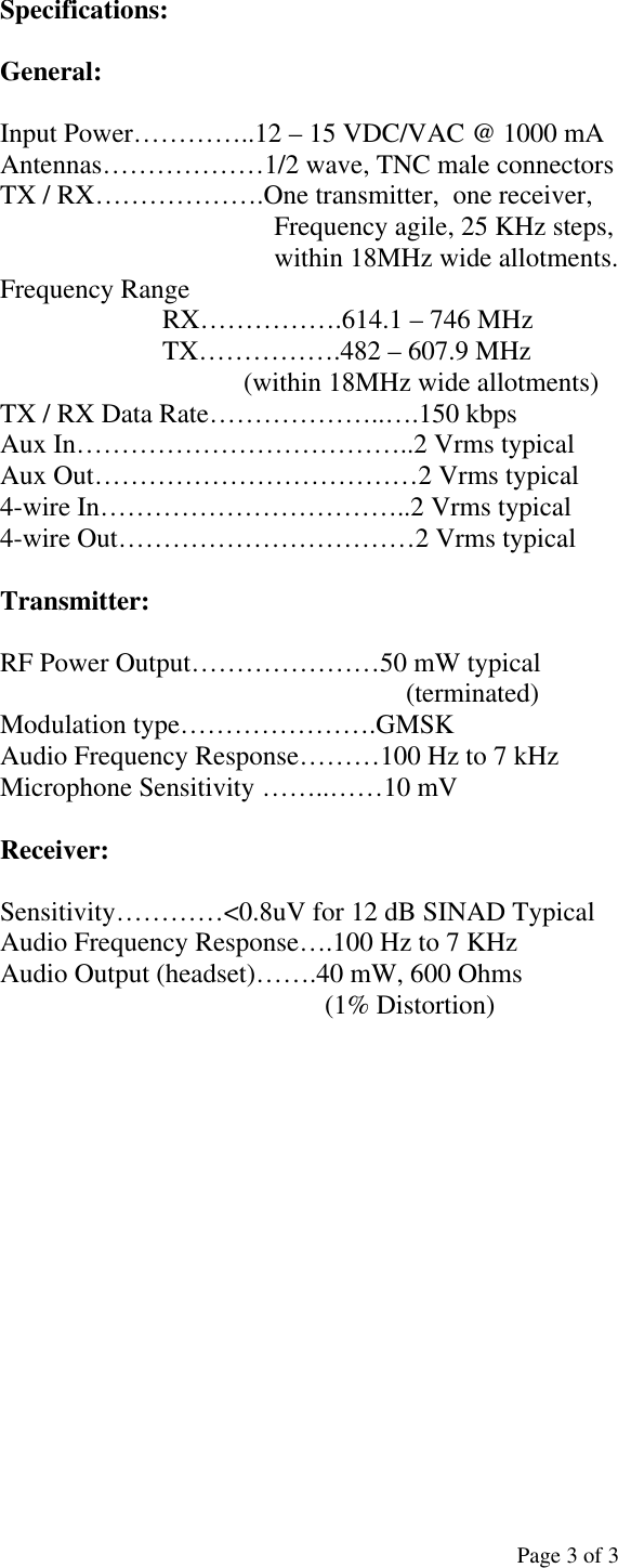
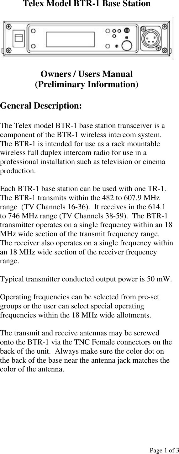
USERS MANUAL
Navigation menu
Upload a User Manual
Namespaces
Wiki Guide
HTML
PDF
Info
Views
User Manual
Discussion / Help
Navigation
![Page 2 of 3 1. On/Off Switch – Turns the base station on/off. 2. [MENU] and [SET] buttons – Used to select menus and set options on the LCD. 3. Backlit LCD. 4. [UP] and [DOWN] buttons - Used to select menus and set options on the LCD. 5. Peak Aux Level Light – Will flash red when the auxiliary input level into the base station is too high. 6. Peak Intercom Level Light – Will flash red when the intercom input levels into the base station are too high. 7. Talk Light – Green when the talk button is active. Will turn red when the microphone level into local headset is too high. 8. Talk Button – Press to enable the audio path from the headset. 9. Headphone Volume – Used to adjust the volume level out to a headphone. 10. Microphone Gain – Adjusts the audio gain from the local headset microphone. 11. Local Headset Jack Pin 1 = Ground Pin 2 = Microphone (Hot) Pin 3 = Audio Out + Pin 4 = Audio Out - 12. Relay Contacts – Normally Open. When activated they close. 13. Receive Antenna Connector – TNC Female connector. The color dot near the connector must match the color of the antenna. 14. Auxiliary Connector – RJ-11 connector used to connect auxiliary audio into and out of a base station. 15. CAN bus – RJ-45 connectors used to connect a base station to a CAN type of bus. 16. Matrix Connector – RJ-11 connector used to connect balance 4-W audio into and out of the base station. 17. Intercom Loop Thru – Two DB15 connectors used to loop intercom audio thru a base station. 18. Intercom Jack – XLR intercom jack to allow audio into the base via XLR connectors instead of DB15 connectors. 19. Power Connector – Input power jack which requires 12 to 15 Volts AC or DC at 1000 mA. 20. Transmit Antenna Connector – TNC Female connector. The color dot near the connector must match the color of the antenna. Controls and Connections 1 2 3 4 7 8 6 5 9 10 11 13 12 15 14 16 17 18 19 20](https://usermanual.wiki/Bosch-Security-Systems/M519/User-Guide-455055-Page-2.png)