Bosch Security Systems M525 2.4GHz ACCESS POINT User Manual XO AP manual
Bosch Security Systems, Inc. 2.4GHz ACCESS POINT XO AP manual
users manual
Page 1 of 3
Telex Model XO-AP Access Point
General Description:
The Telex model XO-AP transceiver is
intended for use as an access point between
multiple XO-1 beltpacks clients. This
enables the beltpacks to communicate with
each other over-the-air.
The XO-AP uses 802.11 technology to
receive / transmit within one channel of the
1 – 11 (2.412 to 2.462 GHz) channels of the
2.4 GHz ISM band. Its operation is license
free.
The transmit and receive antennas are
connected via reverse TNC connectors on
the top of the unit.
The XO-AP is powered via an internal Li-
Ion battery that will provide up to 14 hours
of run time at room temperature. It may also
be run off the AC charger unit supplied with
the system.
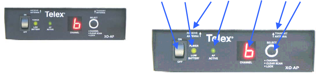
The front panel provides an on/off switch, a
power light, an AP active light, an RF
channel display and a pushbutton for
changing RF channels.
1. On/Off Switch– Turns the power on/off to the
AP.
2. Battery Light –
a. GREEN - Battery OK
b. RED - Battery Low (needs charged)
3. Receive Antenna Jack (Not Pictured) – This
reverse TNC jack is where the receive antenna
coaxial cable should be connected.
4. AP Active Light – This light flashing indicates
that the AP has successfully booted.
5. RF Channel Display – The display indicates
the 802.11 channel for which the unit is set.
6. Transmit Antenna Jack (Not Pictured) – This
reverse TNC jack is where the transmit antenna
coaxial cable should be connected.
7. RF Channel Button –
a. Channel – Hit the button to select the
desired RF channel for the AP.
b. ClearScan – Press and hold the button
until the decimal point starts to flash
(about 4 seconds) then release. The unit
will examine the eleven RF channels
and then pick the one with the least
activity and set the AP on that channel.
c. Lock – Press and hold the button until
the decimal point is on solid (about 10
seconds) then release. The AP will be
lock on the channel displayed. To
unlock, press and hold the button again
until the decimal point is off. Lock only
makes the currently displayed channel
hard for a user to accidentally change
the RF channel.
1234 5
Front Panel
67
Page 2 of 3
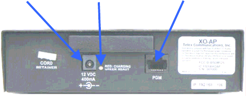
8. Charge Jack – Used to charge the internal
battery or power the unit directly off a wall
outlet. Accepts a 5.5mm x 2.5mm plug with the
center positive. Must be supplied with a 12VDC
regulated power supply with at least a 400mA
current capacity.
9. Charge Light.
a. RED =Beltpack battery is charging.
b. GREEN = Beltpack battery is charged.
10. Programming Jack – This RJ-45 jack is used to
update programming in the unit if ever needed.
Operation
When the XO-AP is turned on the power
light will turn green immediately indicating
power. After 20 seconds, the unit will do a
ClearScan of the 802.11 RF channels. It
will then select the clearest channel. After
this is done, the AP active light will start
flashing. The AP is now ready to act as an
access point for XO-1 beltpacks.
8 9 10
Page 3 of 3
Specifications
Technology……………………………………… 2.4 GHz, IEEE 802.11b
Power……………………………………………. Internal Li-Ion 7.2V, 4000mAhr, Battery.
Typical battery life of 14 hours.
Current Draw……………………………………. 285mA typical with radio card active
RF Frequency Range……………………………. 802.11 Channels 1 – 11 (2.412 to 2.462GHz)
Modulation Technology………………………… DBPSK, DQPSK, CCK
Antenna Connectors…………………………….. Reverse TNC Jacks
RF Output Power (Terminated)………………… 200mW (Maximum)
Data rates……………………………………….. 2 and 5.5 Mbps
Sensitivity (Worst case)………………………… 5.5Mbps, <-91dBm
Access Point Size………………………………. 6.00L x 6.40W x 2.00H inches
Access Point Weight………………………….… 1 lb 2oz
FCC License…………………………………….. No License Required
Regulatory Information
This device complies with Part 15 of FCC rules
and Canada RSS-210. Operation is subject to the
following conditions:
1. This device may not cause harmful
interference.
2. This device must accept any interference
received, including interference that may
cause undesired operation.
3. Use only the manufacturer or dealer supplied
antenna.
4. This equipment complies with FCC radiation
exposure limits set forth for an uncontrolled
environment. The antennas used with this
equipment should be installed and operated
with a minimum distance of 20cm between
the antenna and your body.
5. This device must not be co-located or
operated in conjunction with any other
antenna or transmitter.
To assure continued compliance with FCC
regulations, any changes or modification not
expressly approved by the party responsible
for compliance could void the user’s
authority to operate this equipment.