Bosch Security Systems M529 UHF Audio Base Station User Manual 803257 1aDUMMY vp
Bosch Security Systems, Inc. UHF Audio Base Station 803257 1aDUMMY vp
UserManual.wiki
>
Bosch Security Systems
>
M529 User Manual
User Manual
Navigation menu
Upload a User Manual
Namespaces
Wiki Guide
HTML
PDF
Info
Views
User Manual
Discussion / Help
Navigation


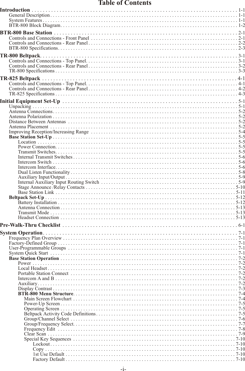
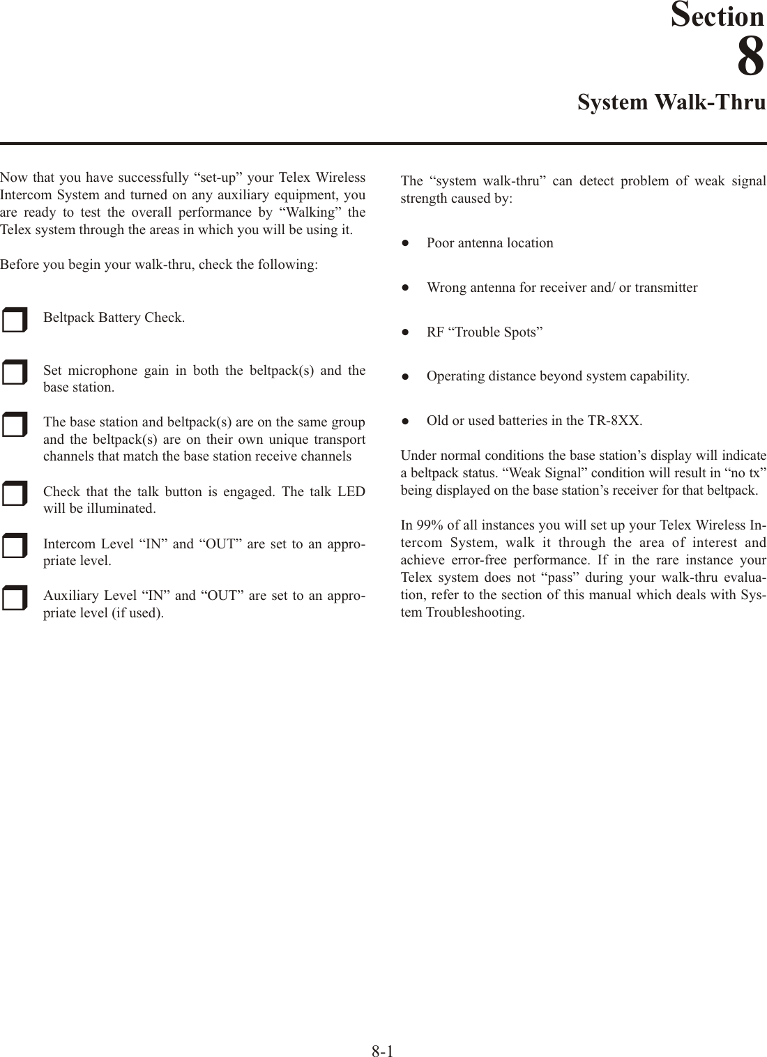
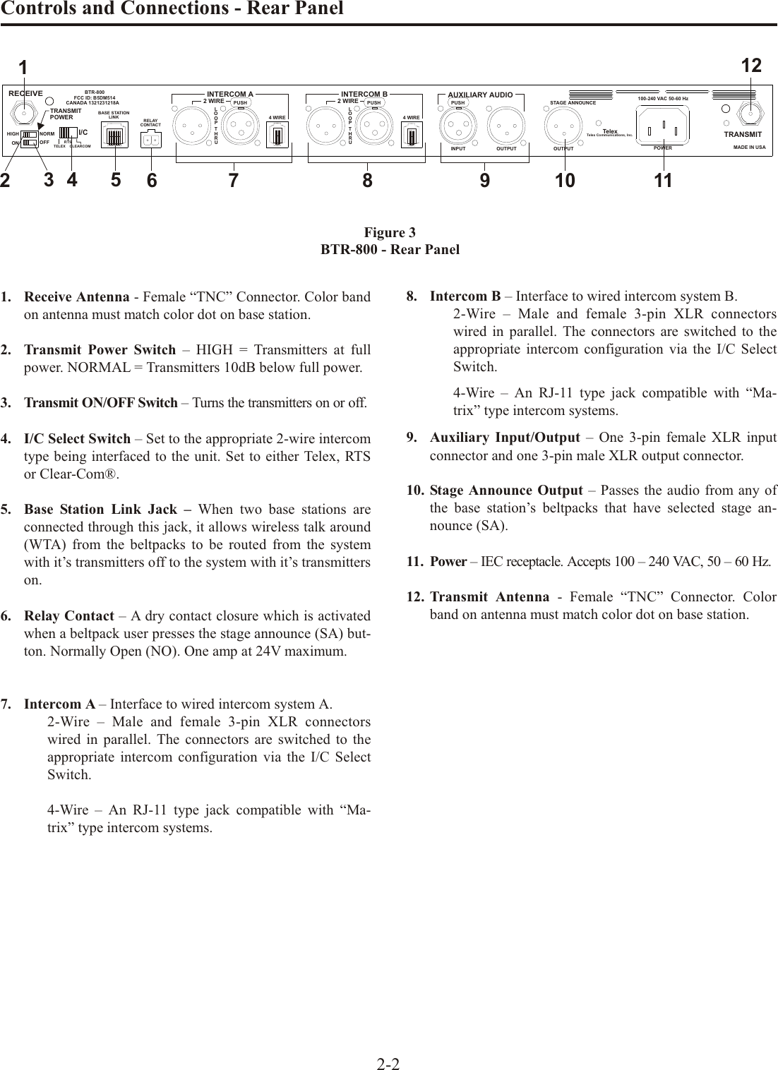
![BTR-800 Base Sta tionCon trols and Con nec tions - Front Panel1. Power switch.2. [Menu] and [Set] but tons – Used to se lect menus and setop tions on the LCD.3. Backlit Graph ics LCD (Liq uid Crys tal Dis play).4. [Up] and [Down] but tons – Used to se lect base sta tionop tions on the LCD.5. Por ta ble Sta tion Con nect – But tons used to en able ordis able the re spec tive re ceiver’s au dio. GREEN LED =Au dio en abled, LED OFF = Au dio dis abled.6. In ter com A Con trols - Wired in ter com A in ter face con -trols. Au dio in put and out put level con trols. 2-wire or4-wire se lect but ton with green LED in di ca tor lights. Se -lected LED will change to RED if the in put lev els are toohigh.7. In ter com B Con trols - Wired in ter com B in ter face con -trols. Au dio in put and out put level con trols. 2-wire or4-wire se lect but ton with green LED in di ca tor lights. Se -lected LED will change to RED if the in put lev els are toohigh.8. Aux il iary Con trols - Wired aux il iary in ter face con trols.Au dio in put and out put level con trols. GREEN LED =Aux. in put en abled. LED will change to RED if the in putlev els are too high.9. Head set Vol ume – Con trols the vol ume to the head setcon nected to #14.10. Head set In ter com Se lect – Con trols the in ter com towhich the lo cal head set is con nected. Each press of thebut ton changes the con nec tion; chan nel A, chan nel B,both.11. Ta lk/Overmod Light – LED is green when talk but ton#13 is ac tive. A nor mal mic gain set ting will cause theLED to flash red on the loud est speech lev els. If the gainis too high, the LED will be red at nor mal speech vol umes.12. Mi cro phone Gain – Ad justs the head set’s mi cro phonegain. Ad justs so that the overmod light #11 flashes fromgreen to red on loud est speech.13. Talk But ton – Press to en able the au dio path from the lo cal head set. LED #11 will turn green when en abled. A quickpress and re lease latches but ton on. If the talk func tion islatched on, press ing the talk but ton again will turn it off.14. Lo cal Head set Con nec tor – Male XLR con nec tor forTelex units, Fe male XLR con nec tor for RTS units. A dy -namic or electret head set mi cro phone is au to mat i cally de -tected.Fig ure 2Lo cal Head set Wiring2-1TALKMIC GAINTALK/O.M.VOLUMESELECTABON/O.M.ON/OFFINOUTAUXILIARYINTERCOM B2 WIRE4 WIRESELECTINOUT2 WIRE4 WIRESELECTINOUTINTERCOM APORTABLE STATION CONNECT1 2 34UPDOWNMENUSETRadioComäBTR-800ClearScanTMCOPY12345678910111213 14Fig ure 1BTR-800 - Front Panel(1) MicrophoneShield (-)(2) MicrophoneAudio (+)(3) HeadphoneHigh (+)(4) HeadphoneLow (-)Telex Units(4) HeadphoneLow (-)(3) HeadphoneHigh (+)(1) MicrophoneShield (-)(2) MicrophoneAudio (+)PUSHSection2(5) (4) HeadphoneLow (-)(3) HeadphoneHigh (+)(1) MicrophoneShield (-)(2) MicrophoneAudio (+)PUSHRTS Units](https://usermanual.wiki/Bosch-Security-Systems/M529/User-Guide-786326-Page-7.png)
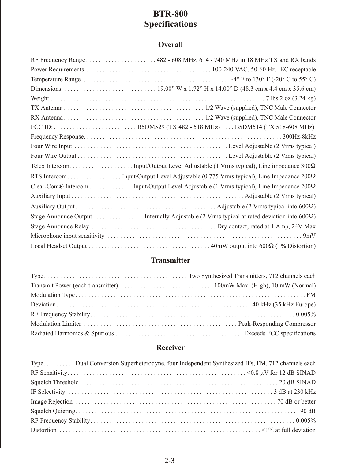
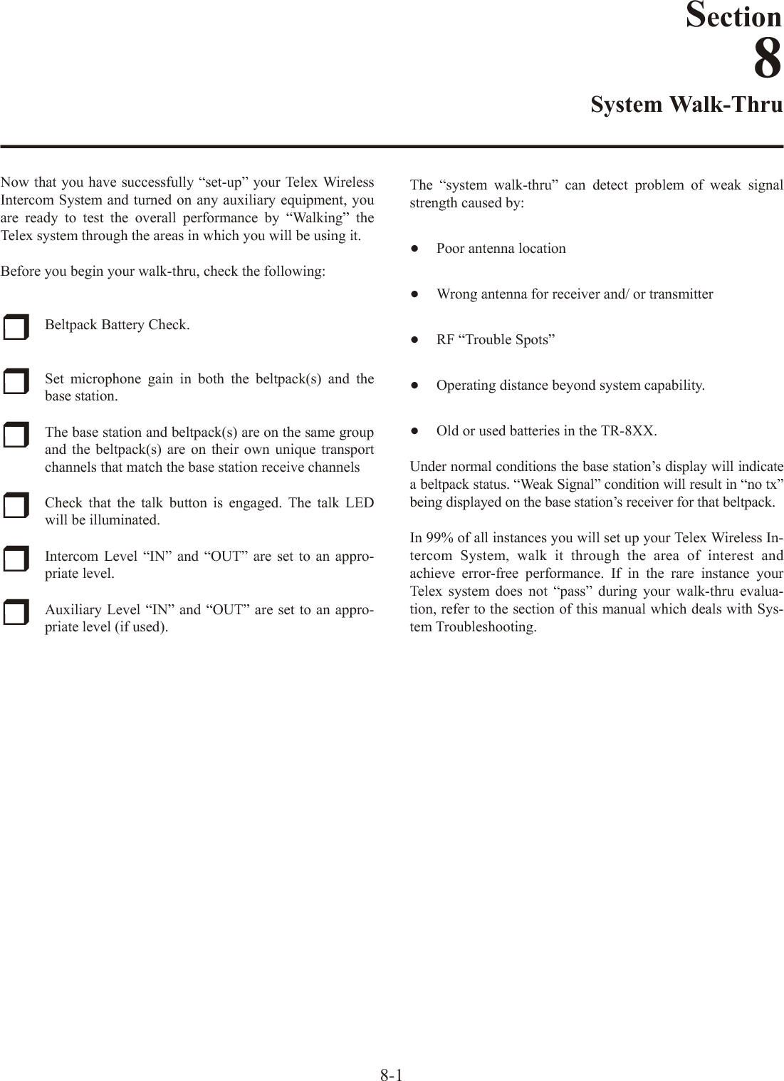
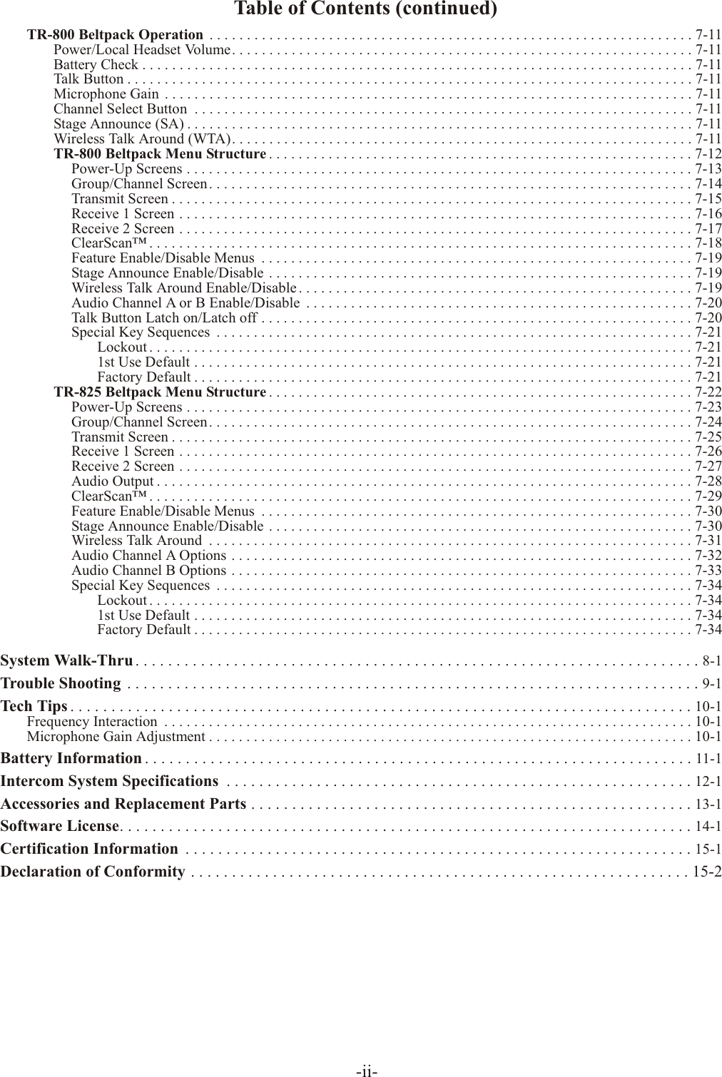
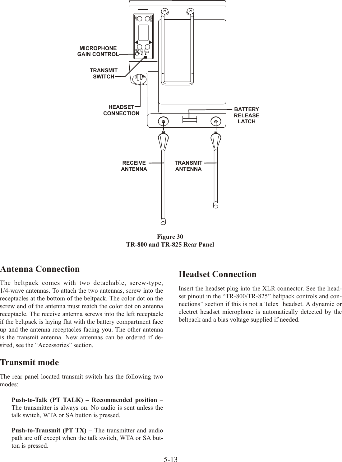
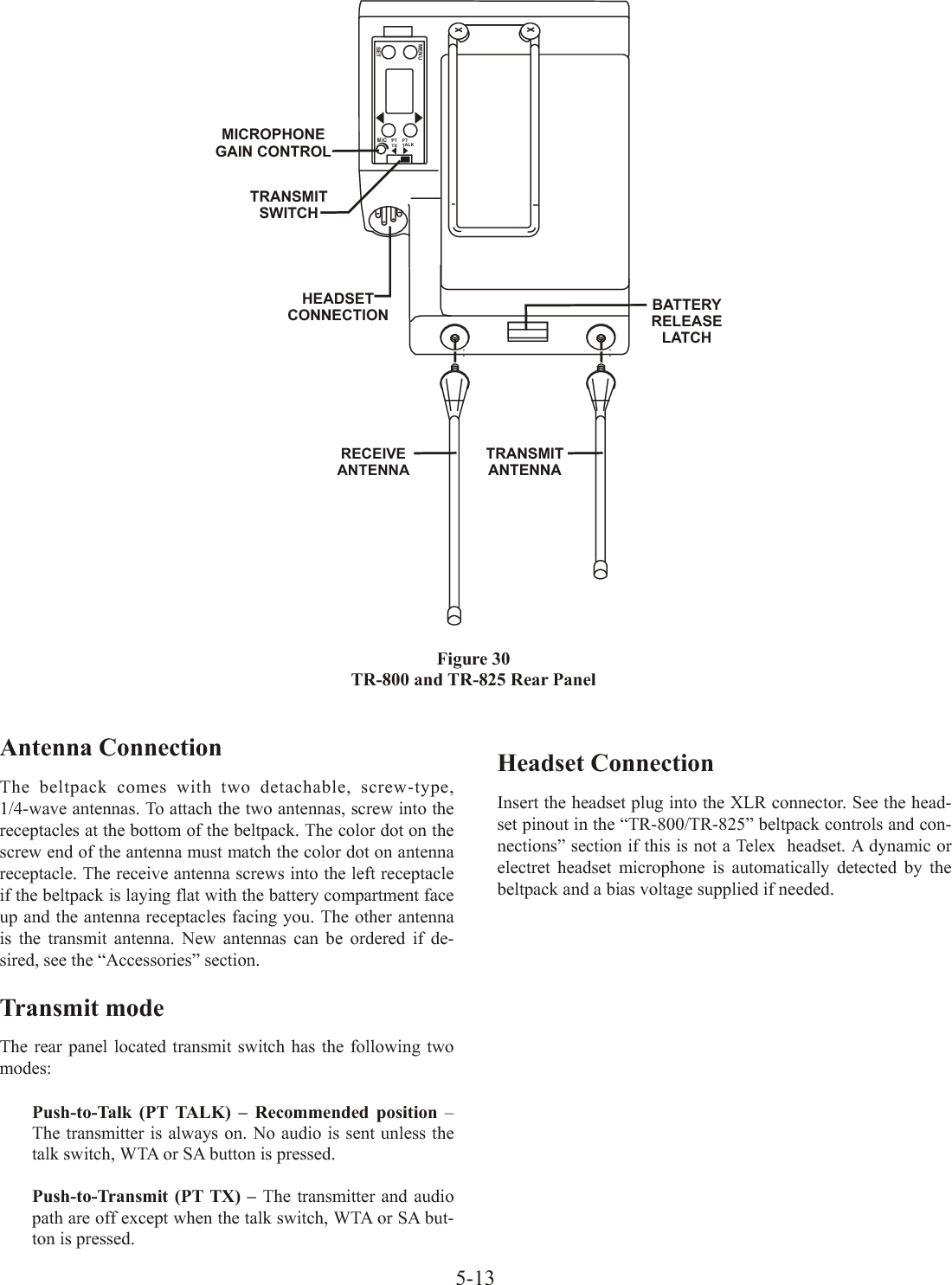
![Con trols and Con nec tions - Rear PanelFig ure 5TR-800 Rear Panel/Con nec tor/An tennas1. [MENU] and [SET] but tons – Used to se lect menus andset op tions on the LCD.2. LCD (Liq uid Crys tal Dis play)3. [UP] and [DOWN] but tons – Used to se lect beltpack op -tions on the LCD.4. Mi cro phone Gain – Ad justs the head set’s mi cro phonegain. Ad just so that the BAT/OM LED will flash at the be -gin ning of most words at nor mal speech lev els5. Push-to-Talk/Push-to-Transmit Switch – Push-to-Talk (PT TALK) – The trans mit ter is al wayson. No au dio sent un less the talk switch, WTA or SAbut ton pressed. Rec om mended po si tion.Push-to-Transmit (PT TX) - The trans mit ter and au dio path are off ex cept when the talk switch, WTA or SAbut ton is pressed.6. Head set Con nec tor – Male XLR con nec tor for Telexunits, Fe male XLR con nec tor for RTS units. A dy namic or electret head set mi cro phone is au to mat i cally de tected bythe beltpack and a bias volt age sup plied if needed.Fig ure 6Head set Jack Wiring7. Bat tery Latch – Press down to en able the bat tery pack tobe re leased. While the latch is held down, slide the bat tery pack about 1/8 inch back, to ward the latch, un til it stops.Then lift out.8. Re ceive An tenna – Screw type ¼-wave re place able an -tenna. The color dot on the screw end of the an tenna mustmatch color dot on an tenna re cep ta cle.9. Trans mit An tenna – Screw type ¼-wave re place able an -tenna. Color dot on the screw end of the an tenna mustmatch color dot on an tenna re cep ta cle.3-2(1) MicrophoneShield (-)(2) MicrophoneAudio (+)(4) HeadphoneLow (-)(3) HeadphoneHigh (+)(1) MicrophoneShield (-)(4) HeadphoneLow (-)(3) HeadphoneHigh (+)(2) MicrophoneAudio (+)RTS UnitsTelex UnitsMENUSETMICPTTX PTTALK66778899MENUSETMICPTTX PTTALK2211334455(1) MicrophoneShield (-)(5) (4) Headphone Low (-)(3) Headphone High (+)(2) MicrophoneAudio (+)](https://usermanual.wiki/Bosch-Security-Systems/M529/User-Guide-786326-Page-12.png)

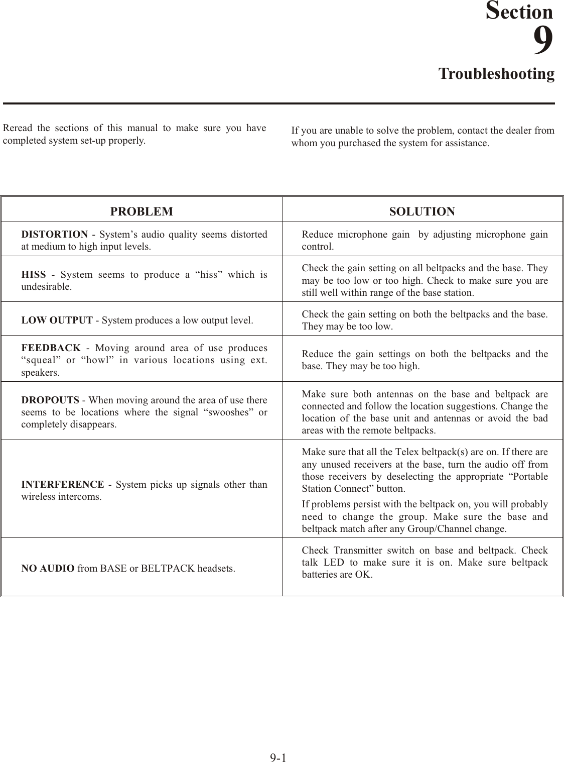
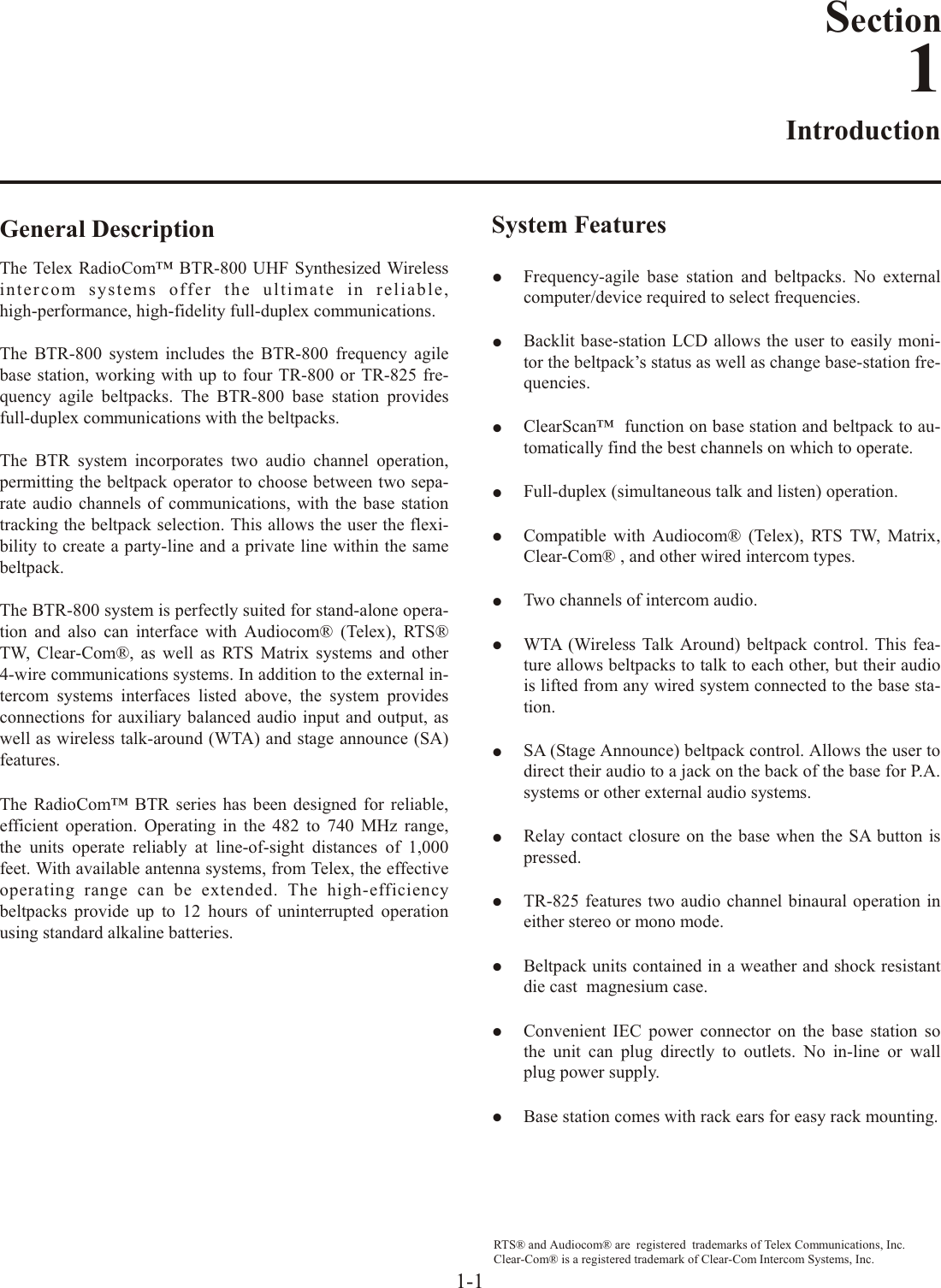
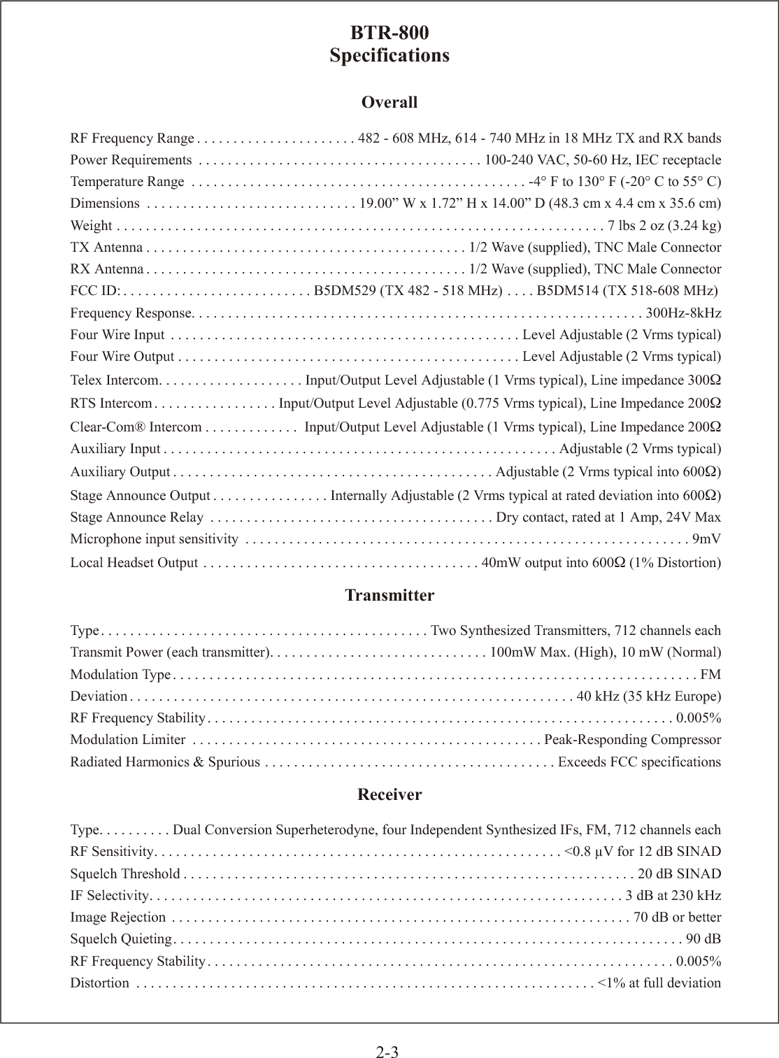
![Con trols and Con nec tions - Rear PanelFig ure 8 TR-825 Rear Panel/Con nec tor/An tennas1. [MENU] and [SET] but tons – Used to se lect menus andset op tions on the LCD.2. LCD (Liq uid Crys tal Dis play)3. [UP] and [DOWN] but tons – Used to se lect beltpack op -tions on the LCD.4. Mi cro phone Gain – Ad justs the head set’s mi cro phonegain. Ad just so that the BAT/OM LED will flash at the be -gin ning of most words at nor mal speech lev els5. Push-to-Talk/Push-to-Transmit Switch – Push-to-Talk (PT TALK) – The trans mit ter is al wayson. No au dio sent un less the talk switch, WTA or SAbut ton pressed. Rec om mended po si tion.Push-to-Transmit (PT TX) - The trans mit ter and au dio path are off ex cept when the talk switch, WTA or SAbut ton is pressed.6. Head set Con nec tor – Male XLR con nec tor for Telexunits, Fe male XLR con nec tor for RTS units. A dy namic or electret head set mi cro phone is au to mat i cally de tected bythe beltpack and a bias volt age sup plied if needed. Fourpin Telex/RTS units are mon au ral. Five pin Telex/RTSunits have a soft ware set-up which grounds or opens pin 3.Fig ure 9Head set Jack Wir ingSin gle sided 5-pin head sets will only re ceive A or B, de pend --ing on how head phone is wired. These head sets must have thebeltpack set for [Ab SEP]7. Bat tery Latch – Press down to en able the bat tery pack tobe re leased. While the latch is held down, slide the bat tery pack about 1/8 inch back, to ward the latch, un til it stops.Then lift out.8. Re ceive An tenna – Screw type ¼-wave re place able an -tenna. The color dot on the screw end of the an tenna mustmatch color dot on an tenna re cep ta cle.9. Trans mit An tenna – Screw type ¼-wave re place able an -tenna. The color dot on the screw end of the an tenna mustmatch color dot on an tenna re cep ta cle.4-2(1) MicrophoneShield (-)(2) MicrophoneAudio (+)(4) HeadphoneLow (-)(3) HeadphoneHigh (+)MENUSETMICPTTX PTTALK66778899MENUSETMICPTTX PTTALK2211334455(1) MicrophoneShield (-)(3) SwitchedHeadphone Ground(2) MicrophoneAudio (+)(4) Headphone (Audio A)(5) Headphone (Audio B)(1) MicrophoneShield (-)(4) HeadphoneLow (-)(3) HeadphoneHigh (+)(2) MicrophoneAudio (+)RTS UnitsTelex Units(1) MicrophoneShield (-)(2) MicrophoneAudio (+)(5) HeadphoneAudio B(4) HeadphoneAudio A(3) Switched Headphone GroundMenu Set[ Ab SEP ][ Ab Add ]PIN 3GNDOPENRESULT ON 5-PINDUAL HEADPHONEA in one side, B in other sideA + B](https://usermanual.wiki/Bosch-Security-Systems/M529/User-Guide-786326-Page-16.png)

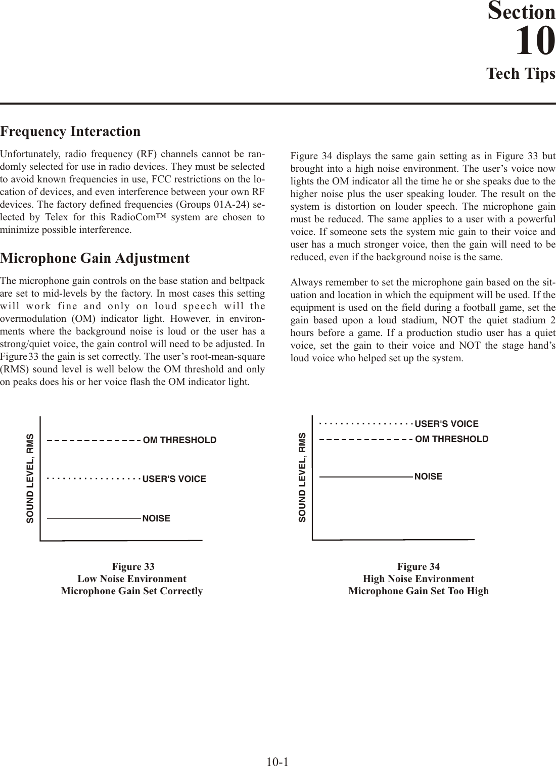
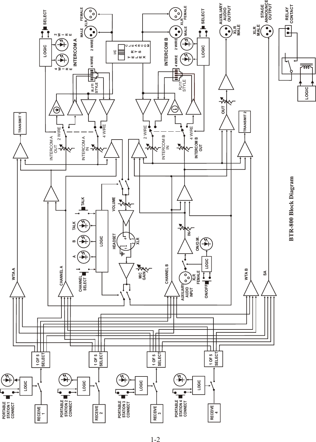
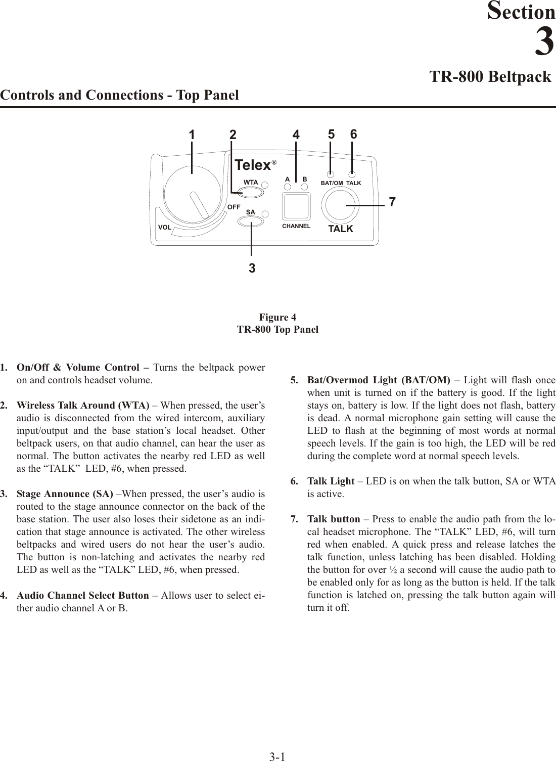
![Stage An nounce / Re lay Con tacts The stage an nounce out put con nec tor is where au dio ex its thebase when any of the beltpacks press the [SA] but ton. Theout put is bal anced au dio though a male 3-pin XLR. The stagean nounce out put level is set at the fac tory for 2 Vrms typ i calout put at rated de vi a tion into 600 Ohms. This should be ad e --quate for most ap pli ca tions. There is an in ter nal level ad just --ment for this out put too. See Fig ure 26 for the lo ca tion of thesmall level trim mer. The top cover of the base sta tion must bere moved for ac cess.A re lay con tact clo sure is also ac ti vated when a beltpack userpresses the [SA] but ton. The con tacts are nor mal open (N.O.).Rat ing: 1 Amp at 24 volts AC/DC max i mum. A “Phoe nix”type con nec tor (sup plied) plugs into the re lay con tact port onthe rear of the base sta tion. This con nec tor pro vides ascrew-type clo sure for an easy con nec tion to wires. 5-10U21VR4STAGE ANNOUNCE LEVEL CONTROLFRONTBACK1 2PHOENIXTYPECONNECTORFig ure 26In ter nal Stage An nounce Level Con trolFig ure 25Re lay Con tact Jack Adapter(Screw Ter mi nal Adapter)RECEIVEHIGHONNORMOFFTRANSMITPOWERI/CTELEX CLEARCOMRTSBTR-800FCC ID: B5DM514CANADA 1321231218A BASE STATIONLINK RELAYCONTACTINTERCOM A2 WIRELOOPTHRU4 WIREINTERCOM B2 WIRELOOPTHRU4 WIREAUXILIARY AUDIOINPUT OUTPUTSTAGE ANNOUNCEOUTPUT POWER100-240 VAC 50-60 HzTRANSMITMADE IN USAPUSHPUSHPUSHTelexTelex Communications, Inc.AUXILIARYINTERFACESTAGE ANNOUNCESTAGE ANNOUNCE RELAYBase Sta tion - Rear PanelPIN 1PIN 2Fig ure 24Re lay Out put Schematic](https://usermanual.wiki/Bosch-Security-Systems/M529/User-Guide-786326-Page-28.png)
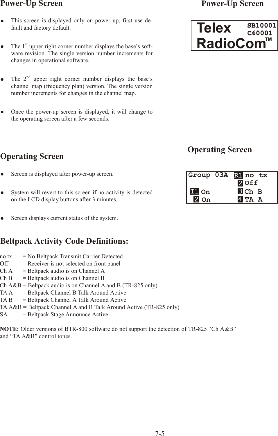
![System Op er a tionFre quency Plan Over viewThe BTR/TR-8XX has 36 fac tory de fined fre quency groupsand 12 user-programmable fre quency groups. A Group de --fines the two base sta tion trans mit fre quen cies and thus thetwo re ceive fre quen cies on all the beltpacks. A Chan nel de --fines a base sta tion re ceive fre quency and thus a beltpacktrans mit frequency. A base sta tion re ceive chan nel that doesnot have a fre quency set for it will have a dash to the right ofit on the Group/Chan nel se lect screen. De tails on set ting fre --quen cies may be found in the “BTR-800 Menu Struc ture” and“TR-8XX Menu Struc ture” in struc tions in this sec tion. Fac tory-Defined GroupsThe 36 fac tory-defined groups were care fully cho sen to avoidcer tain intermod prod ucts and var i ous other pos si ble sourcesof in ter fer ence. The Groups are set and can not be changed. There is a lim ited num ber of chan nels which can be chosenfrom within these groups.The first 24 factory-defined groups (01A – 12B) are “pair”groups that can be used for sin gle (up to 4 beltpacks) and dual(up to 8 beltpacks) BTR-800 sys tems. They are ar ranged01A, 01B, 02A, 02B…011B, 012A, 012B. A “pair” group,like 1A and 1B, have dif fer ent base sta tion transmit fre quen --cies, how ever, they both have the same eight base station re --ceive chan nels from which to choose. Each chan nel rep re sents a unique fre quency. For ex am ple, one BTR-800 could be seton Group 02A and chan nels 01, 02, 03 and 04. The otherBTR-800 could be set on Group 02B chan nels 05, 06, 07 and08. As long as the chan nels are dif fer ent, everything shouldbe fine.The next 12 groups (13 – 24) are sin gle groups that primarilyare used for sin gle (up to 4 beltpacks) BTR-800 sys tems. Thenum ber of chan nels from which to choose from in thesegroups will vary from group to group.User-Programmable GroupsThe 12 user-programmable groups are ini tially empty. Thetrans mit and re ceive fre quen cies are fully editable within these groups. In fact, fac tory-defined groups may be cop ied touser-programmable groups and then ed ited if de sired. See the“BTR-800 Menu Struc ture” and “TR-8XX Menu Struc ture”in struc tions in this sec tion for de tails on how to copy and editfre quen cies. Sys tem Quick StartFol low the list be low to quickly get a base sta tion andbeltpack(s) op er at ing. When com pleted the user should have abase sta tion and 1 to 4 beltpacks up and run ning with full op er --a tional abil ity. The base sta tion will be on Group 01A with itsfour re ceiv ers on chan nels 01, 02, 03 and 04. Each beltpackwill be on Group 01A with a unique trans mit chan nel num bermatch ing one of the base sta tion re ceive chan nels. 1. Plug-in the base sta tion via the sup plied power cord andcon nect the an ten nas. The color dots on the base shouldmatch the color rings on the an ten nas.2. Base sta tion rear panel switches: Trans mit power set toHigh and on.3. En sure base sta tion rear panel IC switch matches at tachedwired in ter com sys tem. If used stand alone or con nected toa 4-wire sys tem then IC switch po si tion is Not Ap pli ca ble.4. Press [MENU] as pow er ing-up the base sta tion. This willplace it on group 01A and set the re ceives on chan nels: 01, 02, 03, and 04.5. Place the front panel IC A and IC B “IN” and “OUT” level con trols in the 12:00 o’clock po si tion. Check that frontpanel IC A and B is in 2-wire for AudioCom (Telex), RTS-TW and ClearCom wired sys tems, and 4-wire for RTSMa trix and stand-alone op er a tion. 6. Place bat ter ies in the beltpacks.7. Re move the rear switch cover on the beltpacks. Set thebeltpack rear panel slide switch to push-to-talk (PTTALK).8. Press [MENU] as pow er ing-up each beltpack. This willplace the beltpack on group 01A with the chan nel 01flash ing.9. Use the [UP] and [DOWN] ar row but tons to change thechan nel to match a channel on the base sta tion. Then press [SET]. If leav ing on chan nel, just press [MENU]. Eachbeltpack should have a unique chan nel num ber. 10. The group/chan nel on the beltpack should now match thegroup and a re ceive chan nel on the base sta tion. Noth ingshould be flash ing on the beltpack screens.11. Plug head sets into the beltpacks and set the mi cro phonegain so the BAT/OM LED will flash at the be gin ning ofmost words at nor mal speech lev els.DONE.7-1Section7](https://usermanual.wiki/Bosch-Security-Systems/M529/User-Guide-786326-Page-35.png)
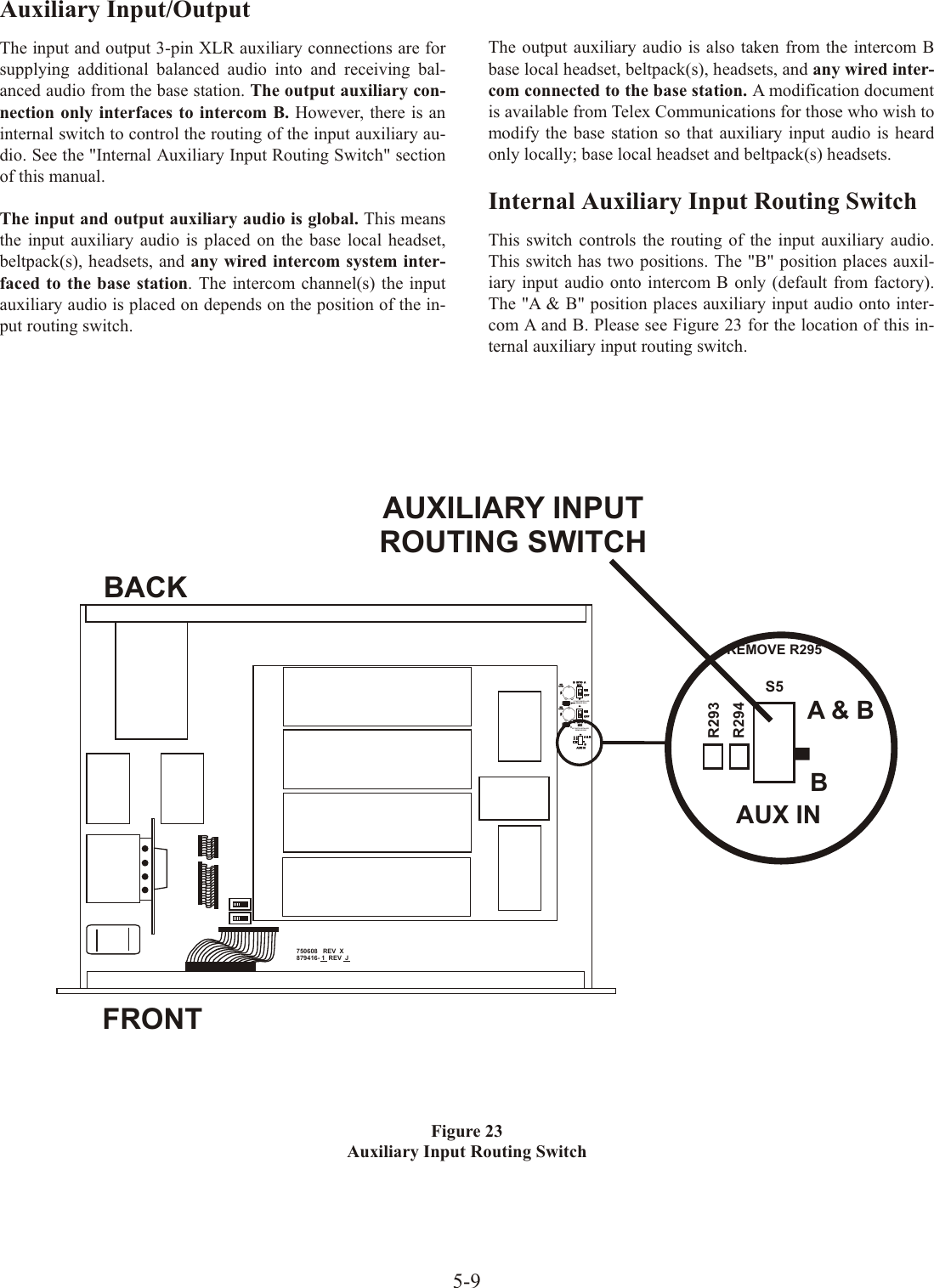
![Base Sta tion Op er a tionPower If you have fol lowed the in struc tions in Sec tion 4, “Ini tialEquip ment Set-Up”, you should now be ready to turn the base sta tion on.Set the base sta tion power switch to the on po si tion, by push --ing the top of the switch.The in ter nal cool ing fan will start im --me di ately and the LCD dis play and front panel in di ca tor lights will come on in five or six sec onds.Lo cal Head setTalk But ton - Press to en able the au dio path from the lo cal head set. The TALK/O.M. LED will turn green when au dio is en abled. A quick press and re lease latches on the but ton. If the talk function is latched on, press ing the talk but tonagain will turn it off. If the lo cal head set is not be ing used, the talk but ton should be off. This keeps ad di tional noiseout of the sys tem.Mi cro phone Gain - Ad justs the head set’s mi cro phonegain. Ad just so the TALK/O.M. LED flashes from greento red on loudest speech. Head set In ter com Se lect But ton - Se lect the in ter comsys tem to con nect to the lo cal head set. Each press of the[SE LECT] but ton changes the con nec tion; Chan nel A,Chan nel B and Both. The cy cle will then re peat. TheLEDs above the [SE LECT] but ton light to in di cate thecur rent se lec tion.Vol ume - Ad just the vol ume to the head set by ro tat ing the vol --ume con trol as re quired for a com fort able lis ten ing vol ume.Por ta ble Sta tion Con nect Se lect the au dio paths from the base sta tion’s four re ceiv ers that you wish to en able. The cor re spond ing LED above the se lectbut ton is on when the au dio path is en abled. If a beltpack userhas their por ta ble sta tion con nect path off at the base, that userwill no lon ger hear their sidetone and their au dio will not bepassed to any one. The user will still be able to hear ev ery one.The se lec tion is re tained in non-volatile mem ory, so it willcome-up where last left if the unit is power cy cled.Al ways dis able un used au dio re ceive paths. This re duces thechances that ex ter nal RF noise can get onto the au dio busesvia an open re ceiver. In ter com A and BIn ter com Se lect But ton - Press the [SE LECT] but ton tochoose be tween 2-wire or 4-wire in ter com sys tems. Thegreen LED will in di cate the cur rent mode of the in ter comchan nel. If the base sta tion is con nected to a 2-wire sys --tem, such as Audiocom (Telex), RTS TW or Clear-Com®, set the in ter com to 2-wire. If it is con nected to afour-wire sys tem, such as RTS Ma trix, set the in ter com to4-wire. It is also pos si ble to have in ter com A con nectedto a 2-wire sys tem and in ter com B con nected to a 4-wiresys tem or vice versa. The se lec tion is re tained innon-volatile mem ory, so it will come-up where last left ifthe unit is power cy cled. In Level Con trol - Ad justs the au dio level of the wiredin ter com sys tem’s in put to the base sta tion.Out Level Con trol - Ad justs the au dio level of the basesta tion’s out put to the wired in ter com sys tem.If the base sta tion is used stand-alone, no wired in ter com sys --tem con nected, it must be set in the 4-wire mode. The 2-wiremode re quires a wired in ter com sys tem or ap pro pri ate load becon nected to the in ter com A or B XLRs. If not loaded, a large gain in crease will take place in the un load in ter com chan nelwhich may be high enough to pro duce a loud “howl ing”sound. Aux il iaryAux il iary In put Se lect But ton - Press the [SE LECT]but ton to turn on or off the aux il iary in put to the base sta --tion. The se lec tion is re tained in non-volatile mem ory, soit will come-up where last left if the unit is power cy cled.In Level Con trol - Ad justs the au dio level of the wiredaux il iary sys tem’s in put to the base sta tion.Out Level Con trol - Ad justs the au dio level of the basesta tion’s out put to the aux il iary XLR plug.The aux il iary out put con nects only to in ter com B. It does notin ter face to in ter com A. The aux il iary in put may be switchedto B in ter com (de fault) or A and B in ter com. See Sec tion 5 for the lo ca tion of this in ter nally lo cated in put rout ing switch. The aux il iary out put is al ways avail able at the back panel out putXLR. It can not be switched on or off like the in put. Both thein put and out put are bal anced au dio ports. Aux il iary in put andout put au dio is global. See Sec tion 5 for more de tails.7-2TALKMIC GAINTALK/O.M.VOLUMESELECTABON/O.M.ON/OFFINOUTAUXILIARYINTERCOM B2 WIRE4 WIRESELECTINOUT2 WIRE4 WIRESELECTINOUTINTERCOM APORTABLE STATION CONNECT1 2 34UPDOWNMENUSETRadioComäBTR-800ClearScanTMCOPYPOWERPORTABLE STATIONCONNECTINTERCOMA AND BAUXILIARYLOCALHEADSETBase Sta tion - Rear Panel](https://usermanual.wiki/Bosch-Security-Systems/M529/User-Guide-786326-Page-36.png)
![BTR-800 Menu StructureMain Screen FlowchartThe fol low ing con tains the base station menu struc ture andref er ences the pages in which fur ther de tail of that menu maybe found.7-4TelexRadioComOperating Screen - Pg. 7-5Power-Up Screen - Pg. 7-5Group/Channel Select Screen - Pg. 7-6[MENU]Group/Frequency Select Screen - Pg. 7-7[MENU]Frequency Edit Screen - Pg. 7-8[MENU](User-Programmed Only)[MENU]Action[MENU]No Action[MENU]+[SET]ClearScanTMClearScan Start-up/Search Screen - Pg. 7-9[MENU]or[SET]ClearScan Result Screen - Pg. 7-9[MENU]SB10001SB10001Group 25u44R1R1OnOnCh ACh BTA A2233T1T122Group 25u44R1R1 Ch 01OnOnCh 02Ch 03Ch 042233T1T122Group 25u44R1R1 705.150565.350554.250707.850710.100715.3002233T1T122Group 25uFreq Edit44Ch1Ch1 705.150565.350554.250707.850710.100715.3002233T1T122Group 03AOK?=[SET]NextTMC60001C6000101 0502 060304 08notxOther Spe cial Key Se quences:Lock out........................7-10Copy .........................7-101st Use De fault .................7-10Fac tory De fault ..................7-10NOTE: Pressing [MENU] within a screen af ter ac tionhas oc curred es capes from that ac tion and places theuser at the cur rent screen. Any ed it ing that had beendone since [SET] had been pressed is aborted.Page](https://usermanual.wiki/Bosch-Security-Systems/M529/User-Guide-786326-Page-38.png)
![Group / Chan nel Se lectThe Group/Chan nel se lect screen al lows the user to change the group and se lect from a pre-determined num ber of chan nelson each re ceiver.•Hit [MENU] once to en ter the Group / Chan nel Se lectScreen from the op er at ing screen. •Hit [SET] to en ter group edit. The group num ber will start flash ing. If [SET] is hit again with out hit ting the ar rows,the dis play will go to re ceive 01 chan nel edit. NOTE: Achan nel that does not have a fre quency set for it will havea dash to the right of it on the group/chan nel se lect screen.•The [UP] / [DOWN] ar rows will change the group num -ber. Hit [SET] again to set the group that was flash ing.Now the group num ber will stop flash ing and R1’s chan -nel num ber will start to flash.•The [UP] / [DOWN] ar rows will change the re ceive chan -nel num ber. Hit [SET] to set the chan nel that was se -lected. Now the sec ond chan nel num ber will start to flash. If [SET] is hit again with out hit ting the ar rows, the dis -play will go to the next chan nel num ber.•Af ter the last re ceive chan nel is de cided upon, hit ting[SET] will set that chan nel in the unit and start you overat the be gin ning of the group/chan nel se lect screen withnoth ing flash ing.•Hitting [MENU] will take you to the group/fre quency se -lect screen. NOTE: Hitting [MENU] af ter ac tiv ity has oc -curred within the screen will re turn to the group/chan nelse lect screen with noth ing flash ing. Any change that hadbeen done be fore the last [SET] was pressed will beaborted.•Set ting two chan nels the same is not al lowed. If a chan nel is al ready set on the screen, the user no lon ger has thatchan nel as an op tion to set into one of the other re ceiv ers. 7-6Group 14T1T1 44R1R1 Ch 01OnOnCh 02Ch 03Ch 04Group / Channel Select2233T1T122Group 14T1T1 44R1R1 Ch 01OnOnCh 02Ch 03Ch 042233T1T122Group 15T1T1 44R1R1 Ch 01OnOnCh 02Ch 03Ch 042233T1T122Group 15T1T1 44R1R1 Ch 05OnOnCh 02Ch 03Ch 042233T1T122[SET][UP] / [DOWN][SET][UP] / [DOWN][SET]Group 15T1T1 44R1R1 Ch 05OnOnCh 06Ch 07Ch 082233T1T122Group 15T1T1 44R1R1 715.000569.700568.500716.700719.700721.6002233T1T122[MENU][UP] / [DOWN][SET] (Last Rx Changed)END](https://usermanual.wiki/Bosch-Security-Systems/M529/User-Guide-786326-Page-40.png)
![Group / Fre quency Se lectThe Group/Fre quency se lect screen al lows a user to set thegroup and se lect from a pre-determined num ber of fre quen cies on each re ceiver. Each fre quency dis played on the right half of the screen corresponds to a chan nel num ber in theGroup/Chan nel Screen.•Press [MENU] twice to go to the Group / Fre quency Se -lect screen from the op er at ing screen. Hit [SET] to startthe group num ber flash ing.•Press the [UP] / [DOWN] ar rows to change the groupnum ber. The fre quen cies listed will re flect what is cur -rently in that group. Hitting [SET] will se lect the groupand start the se lect ing of pre de ter mined fre quen cieswithin that group. The R1 fre quency will start flash ing.NOTE: The group num ber sets the trans mit fre quen ciesof fac tory de fined groups and these are not editable. Inuser-programmed groups these are editable from the fre -quency edit screen.•Pressing the [UP] / [DOWN] ar rows will change the fre -quency of “R1” to the pre-defined fre quen cies avail able.Hitting [SET] will ac cept the change and start you ed it ing the next chan nel. If you had not hit the ar row keys whenthe fre quency was flash ing, but in stead hit [SET], youwould have skipped to the next fre quency to edit.•Af ter the last re ceive fre quency is de cided upon, hit ting[SET] will save that last fre quency and start you over atthe be gin ning of the group/fre quency se lect screen withnoth ing flash ing.•Pressing [MENU] will take you to the op er at ing screen ifthis is a fac tory-defined group. If within a user pro -grammed group, you will be taken to the fre quency editscreen. NOTE: Hitting [MENU] af ter ac tiv ity has oc -curred within the screen will re turn to the group/fre -quency edit screen with noth ing flash ing. Any change that had been done be fore the last [SET] was pressed will beaborted.7-7Group 15T1T1 44R1R1 715.000569.700568.500716.700719.700721.600Group / Frequency Select2233T1T122Group 14T1T1 44R1R1 713.200563.100561.700716.100718.600 721.6002233T1T122Group 14T1T1 44R1R1563.100561.7002233T1T122Group 14T1T1 44R1R1563.100561.7002233T1T122[UP] / [DOWN][SET][UP] / [DOWN][SET] (Last Rx Changed)[UP] / [DOWN][SET]716.100718.600 721.600704.200704.700708.300 709.500704.200Group 14T1T1 44R1R1OnOn2233T1T122[MENU]Ch A Ch Bno txENDno tx](https://usermanual.wiki/Bosch-Security-Systems/M529/User-Guide-786326-Page-41.png)
![Fre quency Edit(User-Programmed Groups Only)This menu only oc curs for user-programmable groups or when copy ing to a user-programable group. The Fre quency Editscreen al lows the user to set the group trans mit fre quen ciesand re ceive chan nel fre quen cies of a user-programmablegroup.•Press [MENU] three times to go to the fre quency se lectscreen from the op er at ing screen. Press [SET] to start thegroup num ber flash ing. This screen al lows the user to setthe group and fre quen cies of user-programmed groupsonly. •Press the [UP] / [DOWN] ar rows to change the groupnum ber. The fre quen cies listed will re flect what is cur -rently in that group. Dashes will be dis played in any slots that are not de fined yet. Pressing [SET] will se lect thegroup and start the se lect ing of fre quen cies within thatgroup. The T1 fre quency will start flash ing.•Pressing the [UP] / [DOWN] ar rows will change the fre -quency of “T1” in 25kHz steps. Pressing [SET] will ac -cept the change and start you ed it ing T2. If you had nothit the ar row keys when the fre quency was flash ing, butin stead press [SET], you would have skipped to the nextfre quency to edit.•Af ter ed it ing the trans mit and the re ceive chan nel fre -quen cies, press ing [SET] will save that last fre quency and send you over to the be gin ning of the group/fre quencyselect screen with noth ing flash ing. NOTE: Once the end of the dis played chan nel list is reached, the last dis playedchan nel lo ca tion will scroll to al low the user to edit the re -main ing chan nels. •Af ter ac tion has oc curred in the fre quency edit screen hit -ting [MENU] will take you one menu back to thegroup/fre quency se lect screen so that the user may seewhat fre quen cies the base re ceiv ers are now on. If no ac -tion had oc curred, then pressing [MENU] will take you to the op er at ing screen. NOTE: Be sides a group change,any ed it ing that oc curs within this screen to fre quen ciesDOES NOT take ef fect un til the user ex its the screen viaset ting the last chan nel or press ing [MENU].7-8Group 25uFreq Edit705.150565.350554.250707.850710.100715.300Group 27uFreq Edit705.150567.800554.250707.850710.100 715.300Group 27uFreq Edit567.800556.725Group 27uFreq Edit569.350556.700[UP] / [DOWN][SET][UP] / [DOWN][SET][UP] / [DOWN][SET]707.850710.100 715.300705.150720.550721.350 721.900718.550Group 27u569.350556.700[SET] or [MENU](Last Ch Changed)710.550714.225 716.800705.950ENDFre quency Edit(User-Programmed Groups Only)](https://usermanual.wiki/Bosch-Security-Systems/M529/User-Guide-786326-Page-42.png)
![ClearScan™ClearScan™ per forms a fre quency scan of the fac tory-defined and any set-up user-programmable groups in or der to find thegroup with the high est num ber of clear re ceive chan nels. Af ter about 20-30 sec onds, the group with the high est num ber ofclear re ceive chan nels will be dis played. The next best groupand so forth may be ac cessed with the [DOWN] and [UP]arrow but tons.•Press and hold [MENU] + [SET] for three seconds to en -ter ClearScan™. The base sta tion will now start search ing all groups for the ones with the great est num ber of re -ceiver chan nels clear of in ter fer ence.•ClearScan™ will dis play the group that has the most in -ter fer ence free re ceive chan nels. These clear chan nels aredis played on the right half of the screen. Press [SET] toplace the base sta tion on this group and re turn to the op er -at ing screen. The first four re ceive chan nels dis playedwill be the ones set for the group. The [UP] / [DOWN]but tons may be used to se lect the next best group and soforth.7-9ClearScanTMGroup 03AOK?=[SET]Next01 0502 060304 08Group 04b 01 05OK?=[SET] PrevNext 060304 08[DOWN][SET]Group 04bT1T1 44R1R1OnOn2233T1T122Ch ACh B TA Ano txENDClearScan™](https://usermanual.wiki/Bosch-Security-Systems/M529/User-Guide-786326-Page-43.png)
![Spe cial Key Se quencesLock out•Press [UP]+[DOWN] for 3 sec onds to lock or un lock thebase sta tion. Pressing [MENU] will still func tion to viewscreens, but [SET] will no lon ger start any ed it ing. ClearScan™ , First use, Fac tory de fault are no lon ger ac -ces si ble. The in ter com chan nel A and B front panel2-wire/4-wire se lec tion is also locked into place. A pad -lock icon will be dis played on the sec ond line of the dis -play to the far left as an in di ca tion that the base sta tion islocked out.Copy•Press [SET]+[DOWN] for 3 sec onds to copy any cur -rently dis played group to a user-programmable group. Copy can be done from the group/chan nel se lect,group/fre quency se lect or fre quency edit screen. Oncepressed, the words, “Copy to” are dis played on the screenwith the first empty user-programmable group flash ing. If all the user-programmed groups were full, than the firstprogramable group is dis played. The [UP] or [DOWN]but tons may be used to se lect a different user-programmable group if de sired. Pressing [SET] pastes fre quen cies/chan -nels to the group and take the user to the fre quency editscreen with “T1” flash ing.1st Use De fault•Press [MENU] while turn ing on the base sta tion to en terthe 1st use de fault setup screen. This places the unit ongroup 01A with the four re ceiv ers set to chan nels 1- 4 ofthe group. Any user-programmed fre quen cies that had been en tered pre vi ously are re tained. If lock out hadbeen ac ti vated, the beltpack co mes up where it was lastleft re gard less of [MENU] be ing pressed on power-up.Fac tory De fault•Pressing all four but tons [MENU]+[SET]+[UP]+[DOWN]at the same time for 3 sec onds places the unit on group01A with the four re ceiv ers set to chan nels 1 – 4 of thatgroup. This is just like base sta tion 1st use de fault, ex ceptthat all user-programmed fre quen cies that had been en -tered pre vi ously are erased. This func tion may take sev -eral sec onds. If lock out had been ac ti vated, the beltpackco mes up where it was last left re gard less of these fourkeys be ing pressed.7-10](https://usermanual.wiki/Bosch-Security-Systems/M529/User-Guide-786326-Page-44.png)
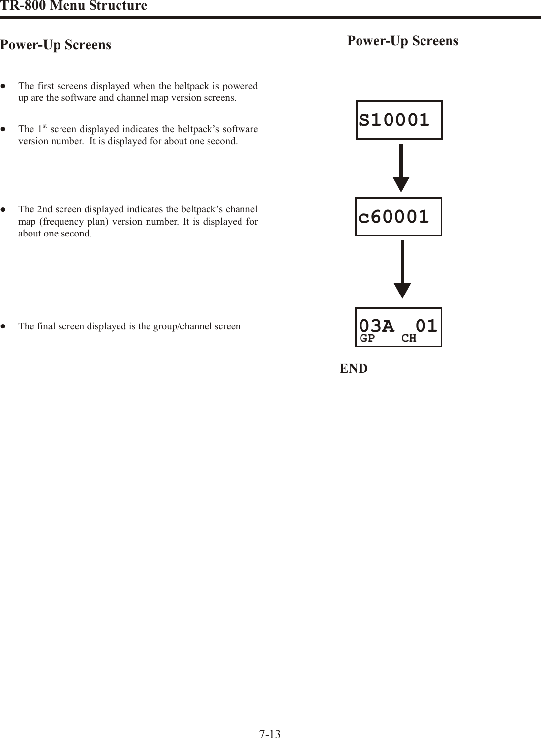
![TR-800 Menu Struc tureBeltpack Menu Struc ture7-12[MENU]S10001c6000103A 01Power-Up Screen - Pg. 7-13 Group/Channel Screen - Pg. 7-14 GP CH[MENU]704.200Transmit Screen - Pg. 7-15 TX[MENU]566.200R1[MENU]570.300R2Receive 1 Screen - Pg. 7-16 Receive 2 Screen - Pg. 7-17 Clr ScnGP04A ScnGP[MENU]+[SET] ClearScan Search Screen - Pg. 7-18ClearScan Result Screen - Pg. 7-18[MENU]or[SET]The fol low ing con tains the main beltpack menu struc ture and ref er --ences the pages in which fur ther de tail of that menu may be found.All beltpack fea tures and spe cial key se quences can only be donefrom the group/channel screen.Beltpack Fea ture En able/Dis able Menus:Stage An nounce (SA) En able/Dis able .........7-19Wire less Talk Around (WTA) En able/Dis able ...7-19Au dio Chan nel A/B Enable/Dis able...........7-20Talk But ton Latching/Non-Latching...........7-20Other Spe cial Key Se quences:Lock out ................................7-211st Use De fault ...........................7-21Fac tory De fault ..........................7-21NOTE: Pressing [MENU] within a screen af ter ac tion has oc curred es capesfrom that ac tion and places the user at the cur rent screen. Any ed it ing thathad been done since [SET] had been pressed is aborted.PagePage](https://usermanual.wiki/Bosch-Security-Systems/M529/User-Guide-786326-Page-46.png)
![TR-800 Menu Struc tureGroup / Chan nel ScreenThe Group/Chan nel screen al lows the user to change thegroup and se lect from a pre-determined num ber of trans mitchan nels.•The screen dis played af ter the beltpack pow er-up screens.•Press [SET] to edit the chan nel num ber. The chan nelnum ber will start flash ing.•Use the [UP]/[DOWN] ar row but tons to change the chan -nel num ber. •Press [SET] to place the beltpack on the chan nel se lected. Once set is pressed, the beltpack trans mit ter will move tothat fre quency and noth ing will be flash ing. Now press[SET] twice to en ter group edit.•Use the [UP]/[DOWN] ar row but tons to change the group num ber. •Press [SET] to place the beltpack on the group se lected. Once set is pressed, the unit re turns to the group/chan neldis play with noth ing flash ing.•Pressing [SET] once more will start the ed it ing se quenceover again. Pressing [MENU] dur ing the group edit willend ed it ing and send the user back at the group/chan nelscreen with out any changes. This ap plies to chan nel ed it -ing too. 7-1403A 01CH03A 01GP03A 01CH03A 01GPCH03A 02GPCH03A 02GPCH05b 02GPCH05b 02GP[SET][UP]/[DOWN][SET]then [SET] twice more[UP]/[DOWN][SET]ENDGroup / Chan nel Screen](https://usermanual.wiki/Bosch-Security-Systems/M529/User-Guide-786326-Page-48.png)
![TR-800 Menu Struc tureTrans mit ScreenThe Transmit screen al lows the user to set the beltpack trans --mit fre quency. Fac tory-defined groups will al low only a setnum ber of pre-defined fre quen cies to be se lected. User-programmable groups will al low the user to change thefre quency in 25kHz steps.•Press [MENU] once from the group/chan nel screen to ar -rive at the trans mit fre quency screen. •Press [SET] to edit the fre quency. The num ber will startflash ing. •Use the [UP]/[DOWN] ar row but tons to change the fre -quency. •Press [SET] to place the beltpack on the fre quency se -lected. If set is held down, dur ing that time thegroup/chan nel is dis played so the user is aware of whattrans mit chan nel the unit has been placed. Once set is re -leased, the unit re turns to the trans mit fre quency screenwith noth ing flash ing.•Pressing [SET] once more will start the ed it ing se quenceover again. Pressing [MENU] dur ing trans mit fre quencyedit will end ed it ing and send the user back to the trans mit screen with out any changes.7-15[SET]03A 03GP CH704.700TX706.500TX[UP]/[DOWN][SET] IS HELD DOWN[SET] IS RELEASED706.500TXEND704.700TXTrans mit Screen](https://usermanual.wiki/Bosch-Security-Systems/M529/User-Guide-786326-Page-49.png)
![TR-800 Menu Struc tureRe ceive 1 ScreenThe Receive 1 screen al lows the user to set the beltpack re --ceive 1 fre quency. This cor re sponds to the base sta tion’s trans --mit 1 fre quency. In fac tory-defined groups re ceive 1 is notchange able. User-programable groups will al low the user tochange the fre quency in 25 KHz steps.•Press [MENU] twice from the group/chan nel screen to ar -rive at the re ceive 1 fre quency screen. •(User-Programmable Groups Only) Press [SET] to editthe fre quency. The num ber will start flash ing. Fac -tory-defined groups can’t be changed; so press ing set willdo noth ing at this screen. User-programmed groups willstart flash ing and al low the user to change the fre quencyin 25kHz steps.•(User-Programmable Groups Only) Use the[UP]/[DOWN] ar row but tons to change the fre quency.•(User-Programmable Groups Only) Press [SET] to placethe beltpack on the fre quency se lected. If set is helddown, dur ing that time the group is dis played so the useris aware of what group the unit has been placed. Once setis re leased, the unit re turns to the re ceive 1 fre quencyscreen with noth ing flash ing.•(User-Programmable Groups Only) Pressing [SET] oncemore will start the ed it ing se quence over again. Pressing[MENU] dur ing re ceive 1 fre quency edit will end ed it ingand send the user back to the re ceive 1 screen with out any changes.7-16554.250[SET]554.250R1R1566.750R1[SET] IS HELD DOWN27uGP[SET] IS RELEASEDEND566.750R1[UP] / [DOWN]Re ceive 1 Screen](https://usermanual.wiki/Bosch-Security-Systems/M529/User-Guide-786326-Page-50.png)
![TR-800 Menu Struc tureRe ceive 2 ScreenThe Re ceive 2 screen al lows the user to set the beltpack re --ceive 2 fre quency. This cor re sponds to the base sta tion’s trans --mit 2 fre quency. In fac tory-defined groups re ceive 1 is notchange able. User-programable groups will al low the user tochange the fre quency in 25 KHz steps.•Press [MENU] three times from the group/chan nel screento ar rive at the re ceive 2 fre quency screen. •(User-Programmable Groups Only) Press [SET] to editthe fre quency. The num ber will start flash ing. Fac -tory-defined groups can’t be changed, so press ing set willdo noth ing at this screen. User-programmed groups willstart flash ing and al low the user to change the fre quencyin 25kHz steps.•(User-Programmable Groups Only) Use the[UP]/[DOWN] ar row but tons to change the fre quency.•(User-Programmable Groups Only) Press [SET] to placethe beltpack on the fre quency se lected. If set is helddown, dur ing that time the group is dis played so the useris aware of what group the unit has been placed. Once set is re leased, the unit re turns to the re ceive 2 fre quencyscreen with noth ing flash ing.•(User-Programmable Groups Only) Pressing [SET] oncemore will start the ed it ing se quence over again. Pressing[MENU] dur ing re ceive 2 fre quency edit will end ed it ingand send the user back to the re ceive 2 screen with out any changes.7-17565.350[SET]565.350R2R2567.850[SET] IS HELD DOWN27uGP[SET] IS RELEASEDEND567.850[UP] / [DOWN]R2R2Re ceive 2 Screen](https://usermanual.wiki/Bosch-Security-Systems/M529/User-Guide-786326-Page-51.png)
![TR-800 Menu Struc tureClearScan™ClearScanTM per forms a fre quency scan of the fac tory-definedand any set-up user-programmable groups in or der to find theclear est group. Af ter about 30 sec onds, the clear est group isdis played. A group is de fined by re ceive 1 and 2 fre quen cies.The next best group and so forth may be ac cessed with the[DOWN] and [UP] ar row but tons.•Press and hold [MENU] + [SET] for three sec onds to en -ter ClearScanTM. The beltpack will now start search ing forthe clear est groups. The group sym bol will flash in di cat -ing the beltpack is scan ning for clear groups.•ClearScanTM will scan all groups. It will then dis play the1st group it came to that had the clear est re ceive chan nels. The [UP] / [DOWN] but tons may be used to se lect thenext best group and so forth. Hit [SET] to place thebeltpack on this group and re turn to the group/chan nelscreen.7-18END04b 01GP CHClr ScnGP04b ScnGP[SET]ClearScan™](https://usermanual.wiki/Bosch-Security-Systems/M529/User-Guide-786326-Page-52.png)
![TR-800 Menu Struc tureStage An nounce En able/Dis able•Press and hold [SET] then press the [SA] but ton to showthe SA en able/dis able screen. The cur rent set ting of thefea ture is dis played on the LCD.•While con tin u ing to hold [SET] press [SA] again to tog -gle the dis play from ON to OFF or back. Re lease the[SET] but ton to ac cept the cur rent dis played set ting andre turn to the Group/Chan nel screen.Wire less Talk Around En able/Dis able•Press and hold [SET] then press the [WTA] but ton toshow the WTA en able/dis able screen. The cur rent set tingof the fea ture is dis played on the LCD.•While con tin u ing to hold [SET] press [SA] again to cy clethe dis play from on, off, then L on (latch on). Re lease the[SET] but ton to ac cept the cur rent dis played set ting andre turn to the Group/Chan nel screen.7-19END03A 01GP CHSA onSA oFFRELEASE [SET]HOLD [SET] AND PRESS [SA]CONTINUE TO HOLD [SET]AND PRESS [SA] AGAINEND03A 01GP CHtA onHOLD [SET] AND PRESS [WTA]CONTINUE TO HOLD [SET]AND PRESS [WTA] AGAINCONTINUE TO HOLD [SET]AND PRESS [WTA] AGAINtA oFFtA LonRELEASE [SET]](https://usermanual.wiki/Bosch-Security-Systems/M529/User-Guide-786326-Page-53.png)
![TR-800 Menu Struc tureAu dio Chan nel A or B Dis able/En able•Press and hold [SET] then press the [CHAN] but ton toshow the chan nel en able/dis able screen. The cur rent set -ting of the fea ture is dis played on the LCD.•While con tin u ing to hold [SET], press the [CHAN] but ton again to move to the next op tion, only chan nel B on. •As you con tinue to hold [SET], press the [CHAN] but tononce more to move to the next op tion, only chan nel A on. If the chan nel but ton was hit once more, the user wouldstart over at the AB ON screen.•Re lease the [SET] but ton to ac cept the cur rent dis playedset ting and re turn to the Group/Chan nel screen.Talk But ton Latch on/Latch off•Press and hold [SET] then press the [TALK] but ton toshow the Talk But ton Latch/Non-Latching screen Thecur rent set ting of the fea ture is dis played on the LCD dis -play.•While con tin u ing to hold [SET] press [TALK] again totog gle the dis play from on to off or back. Re lease the[SET] but ton to ac cept the cur rent dis played set ting andre turn to the Group/Chan nel screen.7-20 b onDisabling Audio Channel A Ab on A onHOLD [SET] AND PRESS [CHAN]CONTINUE TO HOLD [SET]AND PRESS [CHAN] AGAINEND03A 01GP CHRELEASE [SET]CONTINUE TO HOLD [SET]AND PRESS [CHAN] AGAIN l onHOLD [SET] AND PRESS [TALK]END03A 01GP CHRELEASE [SET]CONTINUE TO HOLD [SET]AND PRESS [TALK] AGAINt l oFFt](https://usermanual.wiki/Bosch-Security-Systems/M529/User-Guide-786326-Page-54.png)
![TR-800 Menu Struc tureSpe cial Key Se quencesLock out•Press [UP]+[DOWN] for 3 sec onds to lock or un lock thebeltpack. The words “Loc on” will be dis played when thefea ture is ac ti vated, “Loc oFF” will be dis played when the beltpack is un locked. Pressing [MENU] will still func tionto view screens, but [SET] will no lon ger start any ed it -ing. ClearScan™, First use, Fac tory de fault and Fea tureen able/dis able are no lon ger ac ces si ble. 1st Use De fault•Press [MENU] while turn ing on the beltpack to en ter the1st use de fault setup screen. This places the unit on group01A with chan nel 01 flash ing. Any user-programmedfre quen cies that had been en tered pre vi ously are re -tained. The beltpacks must now be set to dif fer ent trans -mit chan nels us ing the [UP]/[DOWN] but tons. Then[SET] is hit to place the units on those chan nels. If lock -out had been ac ti vated, the beltpack co mes up where itwas last left re gard less of [MENU] be ing pressed onpower-up.Fac tory De fault•Pressing all four but tons [MENU]+[SET]+[UP]+[DOWN] at the same time for three sec onds places the unit ongroup 01A with chan nel 01 flash ing, just like beltpack 1stuse de fault, ex cept the all user-programmed fre quen cies that had been en tered pre vi ously are erased. Af ter thebut tons are re leased, it still may take sev eral sec onds forthe beltpack to re set. The beltpacks must now be set todif fer ent trans mit chan nels us ing the [UP]/[DOWN] but -tons. Then [SET] is hit to place the units on those chan -nels. If lock out had been ac ti vated, the beltpack co mes up where it was last left re gard less of these four keys be ingpressed.7-21](https://usermanual.wiki/Bosch-Security-Systems/M529/User-Guide-786326-Page-55.png)
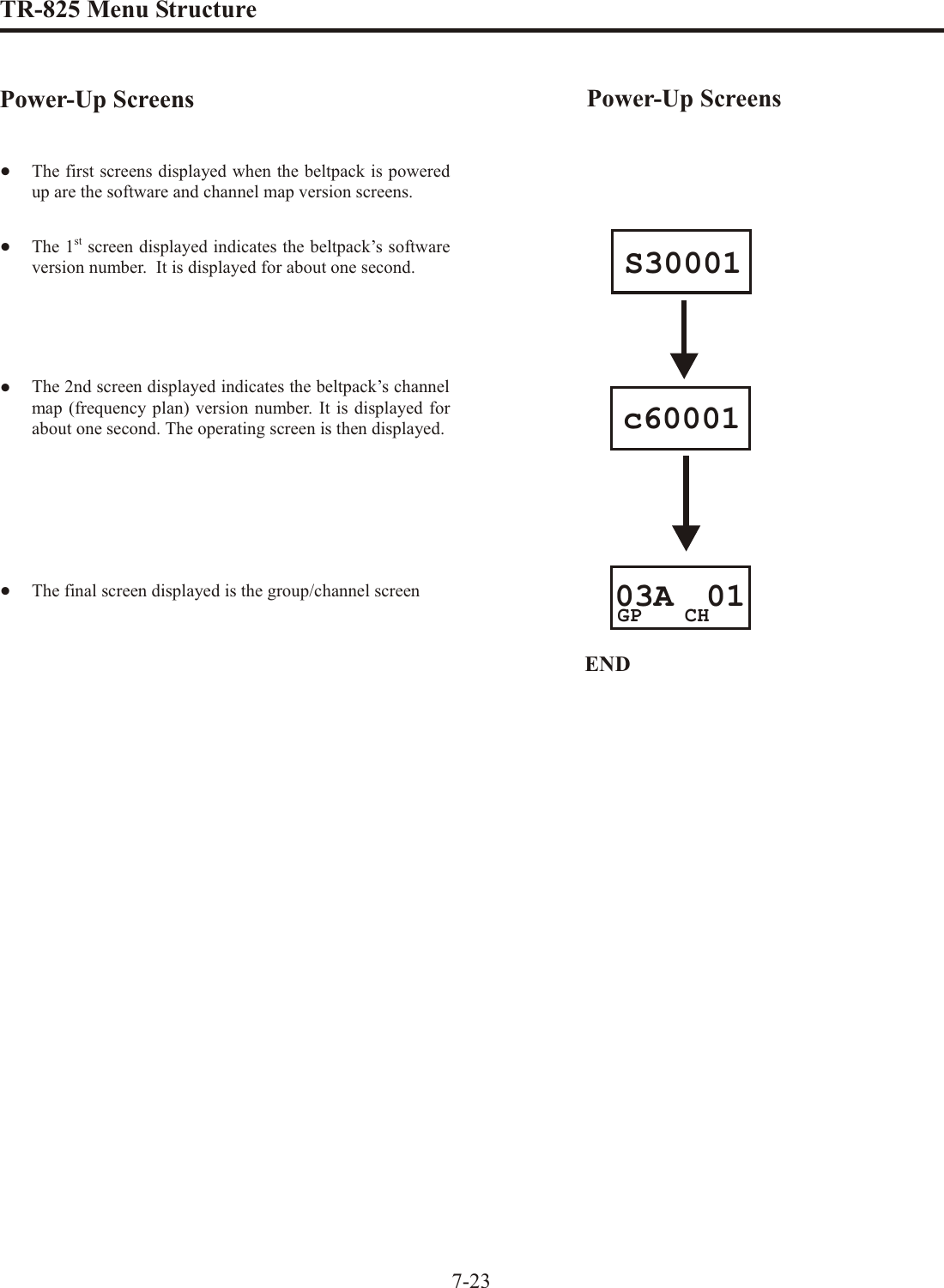
![TR-825 Menu Struc tureBeltpack Menu Struc ture 7-22The fol low ing con tains the main beltpack menu struc ture and ref er --ences the pages in which fur ther de tail of that menu may be found.All beltpack fea tures and spe cial key se quences can only be donefrom the group/channel screen.Beltpack Fea ture En able/Dis able Menus:Au dio Out put ............................7-28Stage An nounce (SA) ......................7-30Wire less Talk Around (WTA)................7-31Au dio Chan nel A .........................7-32Au dio Chan nel B .........................7-33Other Spe cial Key Se quences:Lock out ................................7-341st Use De fault ...........................7-34Fac tory De fault ..........................7-34NOTE: Pressing [MENU] within a screen af ter ac tion has oc curred es capesfrom that ac tion and places the user at the cur rent screen. Any ed it ing thathad been done since [SET] had been pressed is aborted.PagePage[MENU]S30001c6000103A 01Power-Up Screen - Pg. 7-23 Group/Channel Screen - Pg. 7-24 GP CH[MENU]704.200Transmit Screen - Pg. 7-25 TX[MENU]566.200R1[MENU]570.300R2Receive 1 Screen - Pg. 7-26 Receive 2 Screen - Pg. 7-27 Clr ScnGP04A ScnGP[MENU]+[SET] ClearScan Search Screen - Pg. 7-29ClearScan Result Screen - Pg. 7-29[MENU]or[SET][MENU]Ab AddAudio Output - Pg. 7-28](https://usermanual.wiki/Bosch-Security-Systems/M529/User-Guide-786326-Page-56.png)
![TR-825 Menu Struc tureGroup / Chan nel ScreenThe Group/Chan nel screen al lows the user to change thegroup and se lect from a pre-determined num ber of trans mitchan nels.•The screen dis played af ter the beltpack powered-upscreens.•Press [SET] to edit the chan nel num ber. The chan nelnum ber will start flash ing.•Use the [UP]/[DOWN] ar row but tons to change the chan -nel num ber. •Press [SET] to place the beltpack on the chan nel se lected. Once set is pressed, the beltpack trans mit ter will move tothat fre quency and noth ing will be flash ing. Now press[SET] twice to en ter group edit.•Use the [UP]/[DOWN] ar row but tons to change the group num ber. •Press [SET] to place the beltpack on the group se lected. Once set is pressed, the unit re turns to the group/chan neldis play with noth ing flash ing.•Pressing [SET] once more will start the ed it ing se quenceover again. Pressing [MENU] dur ing the group edit willend ed it ing and send the user back at the group/chan nelscreen with out any changes. This ap plies to chan nel ed it -ing also.7-2403A 01CH03A 01GP03A 01CH03A 01GPCH03A 02GPCH03A 02GPCH05b 02GPCH05b 02GP[SET][UP]/[DOWN][SET][UP]/[DOWN][SET]ENDGroup / Chan nel Screen](https://usermanual.wiki/Bosch-Security-Systems/M529/User-Guide-786326-Page-58.png)
![TR-825 Menu Struc tureTrans mit ScreenThe Trans mit screen al lows the user to set the beltpack trans --mit fre quency. Fac tory-defined groups will al low only a setnum ber of pre-defined fre quen cies to be se lected. User-programmable groups will al low the user to change thefre quency in 25kHz steps.•Press [MENU] once from the group/chan nel screen to ar -rive at the trans mit fre quency screen. •Press [SET] to edit the fre quency. The num ber will startflash ing. Fac tory-defined groups will al low only a setnum ber of pre-defined fre quen cies to be se lected.User-programmable groups will al low the user to changethe fre quency in 25kHz steps.•Use the [UP]/[DOWN] ar row but tons to change the fre -quency. •Press [SET] to place the beltpack on the fre quency se -lected. If set is held down, dur ing that time thegroup/chan nel is dis played so the user is aware of whattrans mit chan nel the unit has been placed. Once set is re -leased, the unit re turns to the trans mit fre quency screenwith noth ing flash ing.•Pressing [SET] once more will start the ed it ing se quenceover again. Pressing [MENU] dur ing trans mit fre quencyedit will end ed it ing and send the user back to the trans mit screen with out any changes.7-25[SET]03A 03GP CH704.700TX706.500TX[UP]/[DOWN][SET] IS HELD DOWN[SET] IS RELEASED706.500TXEND704.700TXTrans mit Screen](https://usermanual.wiki/Bosch-Security-Systems/M529/User-Guide-786326-Page-59.png)
![TR-825 Menu Struc tureRe ceive 1 ScreenThe Re ceive 1 screen al lows the user to set the beltpack re --ceiver 1 fre quency. This cor re sponds to the base sta tion’strans mit 1 fre quency. In fac tory-defined groups re ceiver 1 isnot change able. User-programmable groups will al low theuser to change the fre quency in 25kHz steps.•Press [MENU] twice from the group/chan nel screen to ar -rive at the re ceive 1 fre quency screen. •(User-Programmable Groups Only) Press [SET] to editthe fre quency. The num ber will start flash ing. Fac -tory-defined groups can’t be changed; so press ing set willdo noth ing at this screen. User-programmed groups willstart flash ing and al low the user to change the fre quencyin 25kHz steps.•(User-Programmable Groups Only) Use the[UP]/[DOWN] ar row but tons to change the fre quency.•(User-Programmable Groups Only) Press [SET] to placethe beltpack on the fre quency se lected. If set is helddown, dur ing that time the group is dis played so the useris aware of what group the unit has been placed. Once setis re leased, the unit re turns to the re ceive 1 fre quencyscreen with noth ing flash ing.•(User-Programmable Groups Only) Pressing [SET] oncemore will start the ed it ing se quence over again. Pressing[MENU] dur ing re ceive 1 fre quency edit will end ed it ingand send the user back to the re ceive 1 screen with out any changes.7-26554.250[SET]554.250R1R1566.750R1[SET] IS HELD DOWN27uGP[SET] IS RELEASEDEND566.750R1[UP] / [DOWN]Re ceive 1 Screen](https://usermanual.wiki/Bosch-Security-Systems/M529/User-Guide-786326-Page-60.png)
![TR-825 Menu Struc tureRe ceive 2 ScreenThe Re ceive 2 screen al lows the user to set the beltpack re --ceive 2 fre quency. This cor re sponds to the base sta tion’s trans --mit 2 fre quency. In fac tory-defined groups re ceiver 2 is notchange able. User-programable groups will al low the user tochange the fre quency in 25kHz steps.•Press [MENU] three times from the group/chan nel screento ar rive at the re ceive 2 fre quency screen. •(User-Programmable Groups Only) Press [SET] to editthe fre quency. The num ber will start flash ing. Fac -tory-defined groups can’t be changed, so press ing set willdo noth ing at this screen. User-programmed groups willstart flash ing and al low the user to change the fre quencyin 25kHz steps.•(User-Programmable Groups Only) Use the[UP]/[DOWN] ar row but tons to change the fre quency.•(User-Programmable Groups Only) Press [SET] to placethe beltpack on the fre quency se lected. If set is helddown, dur ing that time the group is dis played so the useris aware of what group the unit has been placed. Once set is re leased, the unit re turns to the re ceive 2 fre quencyscreen with noth ing flash ing.•(User-Programmable Groups Only) Pressing [SET] oncemore will start the ed it ing se quence over again. Pressing[MENU] dur ing re ceive 2 fre quency edit will end ed it ingand send the user back to the re ceive 2 screen with out any changes.7-27565.350[SET]565.350R2R2567.850[SET] IS HELD DOWN27uGP[SET] IS RELEASEDEND567.850[UP] / [DOWN]R2R2Re ceive 2 Screen](https://usermanual.wiki/Bosch-Security-Systems/M529/User-Guide-786326-Page-61.png)
![TR-825 Menu Struc tureAu dio Out putThe Au dio Out put screen al lows the user to set the au dio out --put to Mono (Add) or Ste reo (SEP). This op tion only ap pliesto beltpacks with 5 pin head set con nec tors. Sin gle sided 5-pinhead sets will only re ceive A or B Au dio de pend ing on how the head set is wired. Sin gle sided 5-pin head sets must set the au --dio out put to "Ab SEP". The au dio output op tion set ting doesnoth ing with a 4 pin head set con nec tor.•Press [MENU] four times from the group/chan nel screento ar rive at the au dio out put screen•Press [SET] to change the set ting. The op tion will start toflash.•Use the [UP]/[DOWN] ar row but tons to change the au dio out put op tion.•Press [SET] to end ed it ing and ac cept the set ting.7-28ENDAb SEP[SET][SET]Ab SEPAb Add[UP]/[DOWN]]Ab AddAu dio Output](https://usermanual.wiki/Bosch-Security-Systems/M529/User-Guide-786326-Page-62.png)
![TR-825 Menu Struc tureClearScanTMClearScanTM per forms a fre quency scan of the fac tory-definedand any set-up user-programmable groups in or der to find theclear est group. Af ter about 30 sec onds, the clear est group isdis played. A group is de fined by re ceive 1 and 2 fre quen cies.The next best group and so forth may be ac cessed with the[DOWN] and [UP] ar row but tons.•Press and hold [MENU] + [SET] for three sec onds to en -ter ClearScanTM. The beltpack will now start search ing forthe clear est groups. The group sym bol will flash in di cat -ing the beltpack is scan ning for clear groups.•ClearScanTM will scan all groups. It will then dis play the1st group it came to that had the clear est re ceive chan nels(low est RSSI lev els on the two fre quen cies). The [UP] /[DOWN] but tons may be used to se lect the next bestgroup and so forth. Press [SET] to place the beltpack onthis group and re turn to the group/chan nel screen.7-29END04b 01GP CHClr ScnGP04b ScnGP[SET]ClearScan™](https://usermanual.wiki/Bosch-Security-Systems/M529/User-Guide-786326-Page-63.png)
![TR-825 Menu Struc tureStage An nounce En able/Disable•Press and hold [SET] then press the [SA] but ton to showthe SA en able/dis able screen. The cur rent set ting of thefea ture is dis played on the LCD dis play.•While con tin u ing to hold [SET] press [SA] again to tog -gle the dis play from ON to OFF or back. Re lease the[SET] but ton to ac cept the cur rent dis played set ting andre turn to the Group/Chan nel screen.•NOTE: When SA is en abled and pressed, what ever is on;A talk, B talk, or both, goes out. No au dio chan nels showac tive when SA is pressed.7-30END03A 01GP CHSA onSA oFFRELEASE [SET]CONTINUE TO HOLD [SET]AND PRESS [SA]](https://usermanual.wiki/Bosch-Security-Systems/M529/User-Guide-786326-Page-64.png)
![TR-825 Menu Struc tureWire less Talk Around•Press and hold [SET] then press the [WTA] but ton toshow the WTA menu screen. The cur rent set ting of thefea ture is dis played on the LCD dis play. The first screento the right is cur rently set to a de fault of “A” chan nel,nonlatching.•While con tin u ing to hold [SET] press [WTA] again to goto the next se lec tion; Talk Around = “B” chan nel,non-latching.•Talk Around = “A” + “B” chan nels, non-latching.•Talk Around = “Push-But ton”, non-latching. What evertalk but ton is ac tive be comes wire less talk around.•Talk Around = “A” chan nel, latch ing.•Talk Around = “B” chan nel, latch ing.• “A” + “B” chan nels, latch ing.•Talk Around = “Push-Button”, latch ing. What ever talkbut ton is ac tive be comes wire less talk around.•While con tin u ing to hold [SET], press [SA] once again todis play the fi nal menu op tion “Talk Around = Off”. Re -lease the [SET] but ton on any of the above screens to ac -cept the cur rent dis played set ting and re turn to theGroup/Chan nel screen.7-31CONTINUE TO HOLD [SET]AND PRESS [WTA] AGAINEND03A 01GP CHtA oFFHOLD [SET] AND PRESS [WTA]tA btA AbdEF A LdEF bLdEF AbLCONTINUE TO HOLD [SET]AND PRESS [WTA] AGAINCONTINUE TO HOLD [SET]AND PRESS [WTA] AGAINCONTINUE TO HOLD [SET]AND PRESS [WTA] AGAINCONTINUE TO HOLD [SET]AND PRESS [WTA] AGAINCONTINUE TO HOLD [SET]AND PRESS [WTA] AGAINRELEASE [SET]tA PbCONTINUE TO HOLD [SET]AND PRESS [WTA] AGAINtA PbLCONTINUE TO HOLD [SET]AND PRESS [WTA] AGAINtA A](https://usermanual.wiki/Bosch-Security-Systems/M529/User-Guide-786326-Page-65.png)
![TR-825 Menu Struc tureAu dio Chan nel A Options•Press and hold [SET] then hit the [A] but ton to show thechan nel “A” menu screen. The cur rent set ting of the but -ton is dis played on the LCD dis play; Chan nel “A”“Talk-Latching Off”.•While con tin u ing to hold [SET], press the [A] but tonagain to move to the next op tion; Chan nel “A” Talk -Latching On.•As you con tinue to hold [SET], press the [A] but ton oncemore to move to the next op tion, Chan nel “A” Off.•Re lease the [SET] but ton to ac cept the cur rent dis playedset ting and re turn to the Group/Chan nel screen.7-32 A onCONTINUE TO HOLD [SET]AND PRESS [A] AGAINEND03A 01GP CHHOLD [SET] AND PRESS [A]A L on A oFFCONTINUE TO HOLD [SET]AND PRESS [A] AGAINRELEASE [SET]Au dio Chan nel A Op tions](https://usermanual.wiki/Bosch-Security-Systems/M529/User-Guide-786326-Page-66.png)
![TR-825 Menu Struc tureAu dio Chan nel B Op tions•Press and hold [SET] then hit the [B] but ton to show thechan nel “B” menu screen. The cur rent set ting of the but -ton is dis played on the LCD dis play; Chan nel “B”Talk-Latching Off.•While con tin u ing to hold [SET], press the [B] but tonagain to move to the next op tion; Chan nel “B”Talk-Latching On.•As you con tinue to hold [SET], press the [B] but ton oncemore to move to the next op tion, Chan nel “B” Off.•Re lease the [SET] but ton to ac cept the cur rent dis playedset ting and re turn to the Group/Chan nel screen.7-33b onCONTINUE TO HOLD [SET]AND PRESS [B] AGAINEND03A 01GP CHHOLD [SET] AND PRESS [B] b oFFCONTINUE TO HOLD [SET]AND PRESS [B] AGAINRELEASE [SET]b L onAu dio Chan nel B Op tions](https://usermanual.wiki/Bosch-Security-Systems/M529/User-Guide-786326-Page-67.png)
![TR-825 Menu Struc tureSpe cial Key Se quencesLock out•Press [UP]+[DOWN] for 3 sec onds to lock or un lock thebeltpack. The words “Loc on” will be dis played when thefea ture is ac ti vated, “Loc oFF” will be dis played when the beltpack is un locked. Pressing [MENU] will still func tionto view screens, but [SET] will no lon ger start any ed it -ing. ClearScan™, First use, Fac tory de fault, and Fea tureen able/dis able are no lon ger ac ces si ble. The words “Locout” will be flashed on the screen if any ed it ing is at -tempted dur ing lock out.1st Use De fault•Press [MENU] while turn ing on the beltpack to en ter the1st use de fault setup screen. This places the unit on group01A with chan nel 01 flash ing. Any user-programmedfre quen cies that had been en tered pre vi ously are re -tained. The beltpacks must now be set to dif fer ent trans -mit chan nels us ing the [UP]/[DOWN] but tons. Then[SET] is hit to place the units on those chan nels. If lock -out had been ac ti vated, the beltpack co mes up where itwas last left re gard less of [MENU] be ing pressed onpower-up.Fac tory De fault•Pressing all four but tons [MENU]+[SET]+[UP]+[DOWN] at the same time places the unit on group 01A with chan -nel 01 flash ing, just like beltpack 1st use de fault, ex ceptthe all user-programmed fre quen cies that had been en -tered pre vi ously are erased. The beltpacks must now beset to dif fer ent trans mit chan nels us ing the [UP]/[DOWN] but tons. Then [SET] is pressed to place the units onthose chan nels. If lock out had been ac ti vated, thebeltpack co mes up where it was last left re gard less ofthese four keys be ing pressed.7-34](https://usermanual.wiki/Bosch-Security-Systems/M529/User-Guide-786326-Page-68.png)