Bosch Security Systems M532 Wireless 2.4 GHz Intercom Base Station User Manual User s Manual
Bosch Security Systems, Inc. Wireless 2.4 GHz Intercom Base Station User s Manual
User's Manual

BTR-240 Users Manual - Preliminary Page 1 of 8
Rev D – 4 / 18 / 2011
RTS Model BTR-240
Base Station
Owners / Users Manual
(Preliminary Information)
General Description
The RTS model BTR-240 base station
transceiver is a rack mountable, full-duplex,
wireless intercom radio. The base station
provides a central relay location which
handles the audio traffic between the TR-
240 beltpacks.
A BTR-240 base station can be used to
support up to eight full-duplex wireless TR-
240 beltpacks and many more for beltpacks
in push-to-transmit mode.
The BTR-240 uses the IEEE 802.11b
technology to transmit / receive within one
channel of the 1 – 11 (2.412 to 2.462 GHz)
allowable channels of the 2.4 GHz ISM
band. Operation of the BTR-240 is license
free.
The typical line-of-sight distances for the
system may be 300 feet.
The transmit and receive antennas are
connected via unique reverse TNC
connectors on the rear panel of the unit.
The BTR-240 is powered via a 12 – 15 VDC
receptacle on the rear panel. A 12 VDC
power supply is supplied with the BTR-240.
The front panel LCD display and buttons
allow the following menus to be obtained:
• RF operating channel
• Microphone gain
• Sidetone level
• Transmit squelch setting
• 2W / 4W intercom type settings and
levels
• Auxiliary In / Out settings and levels.
• Speaker output setting and level.
The front panel also has an on/off power
control. A talk button, talk light, channel
select button, channel select lights, and
volume are also available for a user at the
base station local headset.
BTR-240 Users Manual - Preliminary Page 2 of 8
Rev D – 4 / 18 / 2011
Controls and Connections
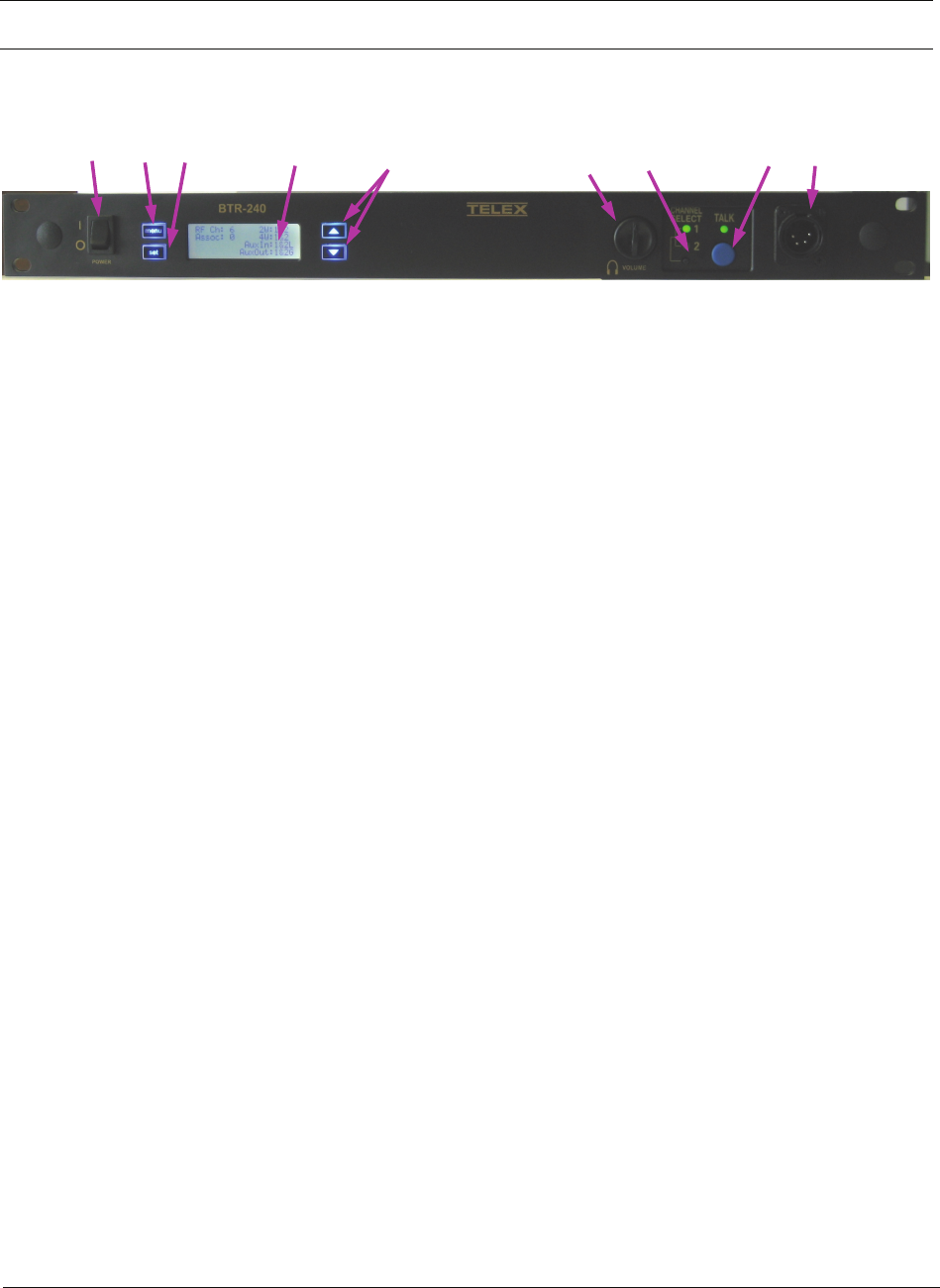
Figure 1
BTR-240 – Front Panel
1. Power on/off switch – turns the power on/off to
the BTR-240.
2. <Menu> button – used to navigate the menu
options on the LCD.
3. <Set> button – used to navigate the menu and
select options on the LCD.
4. Backlit Graphics LCD (liquid crystal display).
5. <Up> and <Down> buttons – used to navigate
the menu and select options on the LCD.
6. <Volume> control knob – controls the volume
for the local headset.
7. <Channel Select> button – Controls the
intercom to which the local headset is connected.
Each press of the button changes the connection;
channel 1, channel 2, both. The corresponding
LEDs will be illuminated.
8. <Talk> button – Press to enable the audio path
from the local headset. The green LED above
the <Talk> button will be illuminated when
active.
9. Local Headset Connector – Male XLR
connector for Telex units, female XLR connector
for RTS units. A dynamic or electret headset
microphone is automatically detected.
1 2 3 4 59
8
76
BTR-240 Users Manual - Preliminary Page 3 of 8
Rev D – 4 / 18 / 2011
Controls and Connections (cont.)
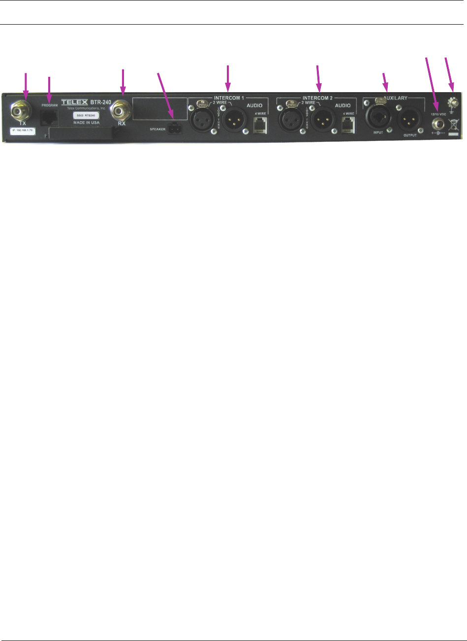
Figure 2
BTR-240 – Rear Panel
1. Transmit Antenna – reverse “TNC” connector.
2. Program Input – this RJ-45 jack is used for
wired Ethernet connections, configuration, and to
update programming in the unit if ever needed.
3. Receive Antenna – reverse “TNC” connector.
4. Speaker Output – one 2-pin connector to attach
cables and a speaker (1Wrms max into 8Ohms).
5. Intercom Channel 1 Input / Output – Interface
to wired intercom system 1.
2-Wire – male and female 3-pin XLR
connectors wired in parallel. The
connectors are switched to the appropriate
intercom configuration via the menu
options.
4-Wire – an RJ-11jack compatible with
“Matrix” type intercom systems.
6. Intercom Channel 2 Input / Output – Interface
to wired intercom system 2.
2-Wire – male and female 3-pin XLR
connectors wired in parallel. The
connectors are switched to the appropriate
intercom configuration via the menu
options.
4-Wire – an RJ-11jack compatible with
“Matrix” type intercom systems.
7. Auxiliary Input / Output – One 3-pin female
XLR / ¼ inch combination input connector and
one 3-pin male XLR output connector.
8. DC Input Jack – Accepts 12-15 VDC, 2.0
Amps to power the base station from a D.C.
source.
9. Chassis Ground –grounding point of the base
station.
1 2 3 4 58
7
69
BTR-240 Users Manual - Preliminary Page 4 of 8
Rev D – 4 / 18 / 2011
Operation
When the BTR-240 is turned on, the backlight
of the LCD and menu buttons will illuminate to
indicate power. The unit takes approximately
25 seconds to boot and its status is indicated
with a progress bar on the LCD.
After the unit has booted successfully, the Start-
up screen displays the unit model and software
versions for approximately 3 seconds.
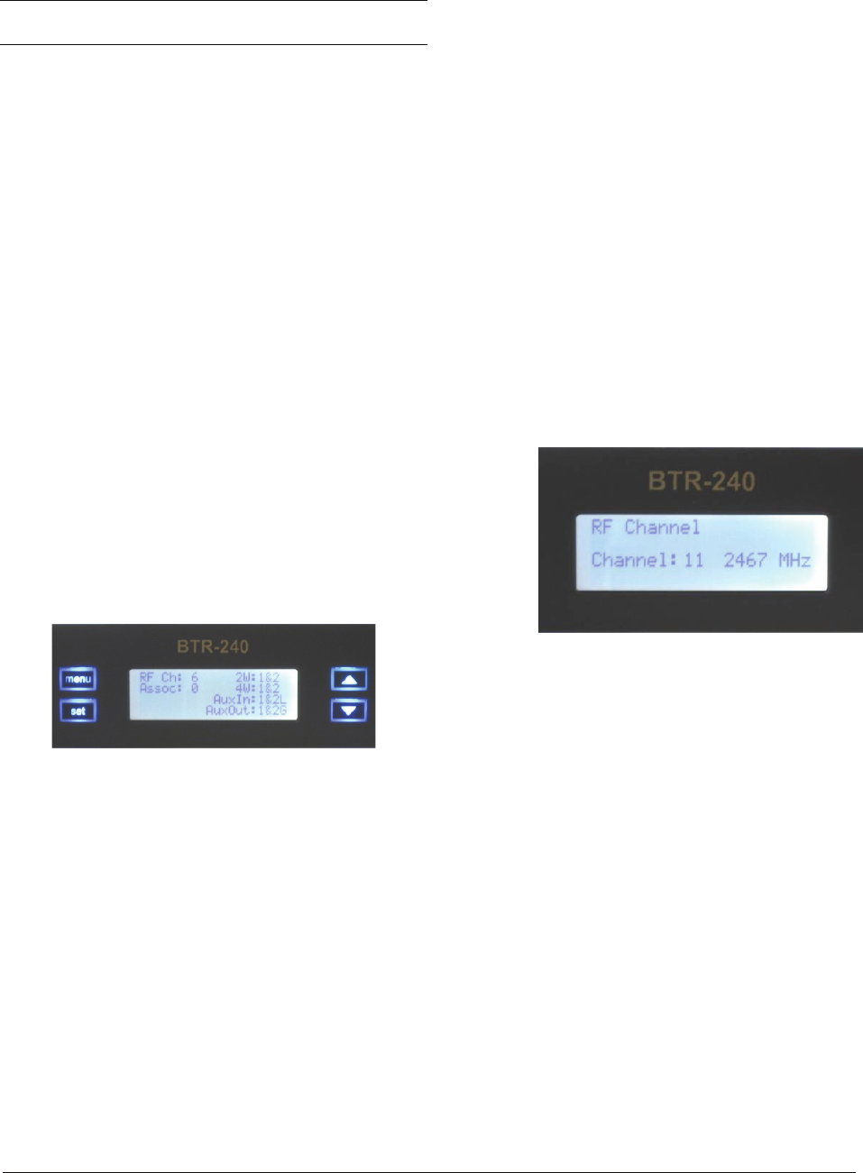
The Status Screen is the main information
screen of the base station. It displays the current
status of the system including:
• RF Channel of operation
• Association (how many full-duplex
beltpacks are associated with the base
station)
• 2W / 4W intercom settings
• Auxiliary input / output settings
• Speaker setting indicator
Once the Status Screen is displayed, it is ready
to act as an access point and TR-240 beltpacks
can be turned on. Once the TR-240 beltpacks
are on in “wireless” mode, they will associate
with the RF channel selected at the base station.
1 Setting the RF Channel
The RF channel can be changed by two different
methods:
• Manual RF Channel Selection
• ClearScan™
NOTE: The RF channel of operation setting is
remembered and the unit will continue to boot
on the same channel until it is set differently by
the user.
NOTE: The RF channel of operation needs to
be verified / set before turning on the TR-240
beltpacks. If a beltpack is already associated
with a base station, it may not continue to
associate once the channel is changed. If this
occurs, the beltpack will need to be rebooted.
1.1 Manual RF Channel Selection
To manually select an RF channel, navigate to
the “RF Channel” menu item and press the
<Set> button.
The current RF channel will be blinking
indicating that the channel is in “set” mode and
ready to be changed.
Using the <Up> and <Down> buttons, the RF
channel is increased and decreased,
respectively.
Once the desired RF channel has been identified
and blinking, pressing the <Set> button will
select it and save the settings. Once the channel
is set, the display will stop blinking and the user
can either press <Set> again to re-enter “set”
mode and change it, or press <Menu> to go
back a menu screen.
After navigating back to the Status Screen, the
new current RF channel of operation is
indicated.
BTR-240 Users Manual - Preliminary Page 5 of 8
Rev D – 4 / 18 / 2011
NOTE: If the <Menu> button is pressed and
held for approximately half a second, the LCD
will abort any current changes if in “set” mode
and immediately return to the Status Screen.
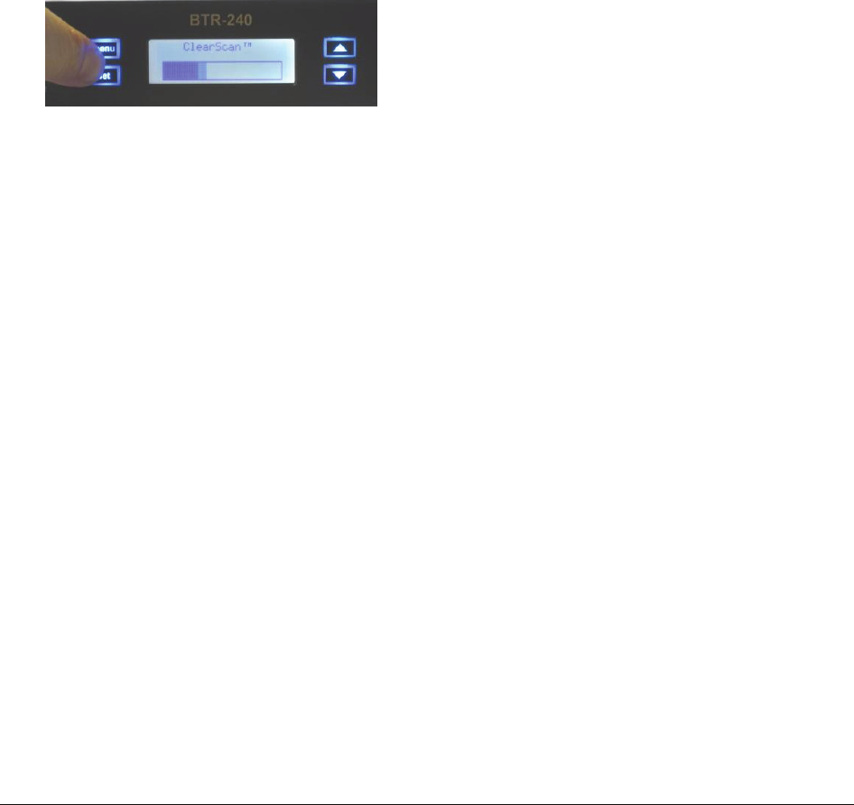
1.2 ClearScan™
A user may also run a ClearScan™ from the
front panel to automatically select the most
available RF channel for use.
A ClearScan™ is performed from by pressing
the <Menu> + <Set> buttons on the front panel
simultaneously for approximately 3 seconds.
Once the ClearScan™ operation is initiated, the
scanning status is indicated by a progress bar on
the LCD.
After the operation has been performed, the
LCD returns to the Status Screen to indicate the
current RF channel of operation.
NOTE: The RF channel of operation needs to
be verified / set before turning on the TR-240
beltpacks. If a beltpack is already associated
with a base station, it may not continue to
associate once the channel is changed. If this
occurs, the beltpack will need to be rebooted.
2 Local Headset Configuration
There are several ways to configure the local
headset at the base station front panel. Settings
for the local headset include the following:
• Talk Button
• Channel Select Button
• Local Headset Volume
• Microphone and Sidetone Levels
2.1 Talk Button
Pressing the <Talk> button on the front panel
will enable and disable the audio path from the
headset microphone. The green talk light will
be illuminated when the microphone path is
enabled. The green talk light will be off when
the microphone path is disabled.
2.1.1 Momentary
Press and hold the <Talk> button for longer
than ½ second and the microphone path will be
enabled. The microphone path will be disabled
when the <Talk> button is released.
2.1.2 Latch
Tap the <Talk> button for less than ½ second
and the microphone path latch and remain
enabled. Tap the <Talk> button again to turn
off the latch and disable the microphone path.
2.2 Channel Select Button
Pressing the <Channel Select> button will select
the intercom channel for the local headset. Each
press of the button will cycle through the
options; Intercom 1, Intercom 2, both. The
green LEDs above the button will be
illuminated for which intercom channel is
currently active for the local headset.
2.3 Local Headset Volume
The local headset volume can be controlled
from the front panel by turning the <Volume>
knob clockwise and counterclockwise to
increase and decrease the volume, respectively.
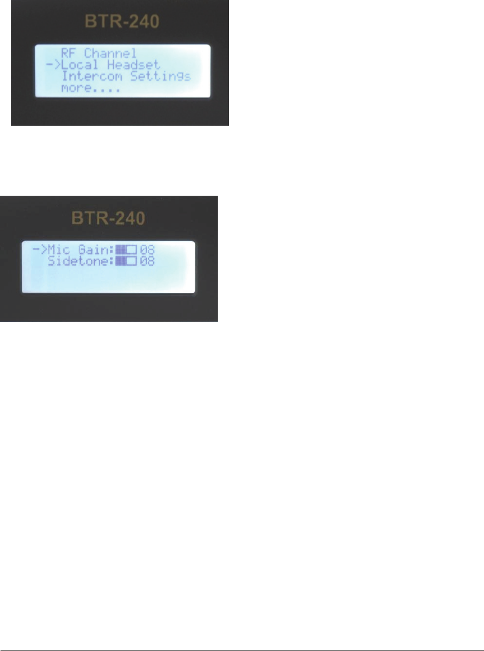
2.4 Microphone and Sidetone Levels
The microphone gain and sidetone level can be
adjusted by navigating the menu on the LCD to
the “Local Headset” option and pressing the
<Set> button.
BTR-240 Users Manual - Preliminary Page 6 of 8
Rev D – 4 / 18 / 2011
Once in the “Local Headset” menu option, the
“Mic Gain” and “Sidetone” levels are available
for adjustment.
Using the <Up> and <Down> buttons to
navigate the cursor to the desired level to
change. After pressing the <Set> button, the
cursor and the level number will blink
indicating that the base station is in “set” mode.
Now, the <Up> and <Down> buttons can be
used to increase and decrease the levels,
respectively. Once the desired level is obtained,
the setting is selected and saved by pressing the
<Set> button again.
Once the microphone gain or sidetone level is
set, the cursor and the level number will stop
blinking. At this time a user can press <Set>
again to re-enter “set” mode and change levels,
press <Up> or <Down> to select a different
level for adjustment, or press <Menu> to go
back a menu screen.

BTR-240 Users Manual - Preliminary Page 7 of 8
Rev D – 4 / 18 / 2011
Specifications
Technology……………………………………… 2.4 GHz, IEEE 802.11b
Power……………………………………………. 12-15 VDC, external DC power supply
Current Draw……………………………………. 1.1 Amps (max)
RF Frequency Range……………………………. 802.11 Channels 1 – 11 (2.412 to 2.462GHz)
Modulation Technology………………………… CCK
Antennas………………………………………… Reverse TNC jacks for external antennas
RF Output Power (Terminated)………………… 100mW (maximum peak)
Data rate…………………………….………….. 5.5 Mbps (locked into)
Sensitivity (Worst case)………………………… 5.5Mbps, < -91dBm
Frequency Response…………………………….. 400 Hz to 3900 Hz
Dynamic Range…………………………………. 66 dB
Audio Output (headset)…………………………. 100mW, 300 Ohms (1% Distortion)
Beltpack Size……………………………………. 7.50L x 19W x 1.75H inches
Beltpack Weight………………………………… 3 lb 7.5 oz
FCC License…………………………………….. No License Required
FCC
This device complies with Part 15 of FCC rules.
Operation is subject to the following conditions:
1. This device may not cause harmful
interference.
2. This device must accept any interference
received, including interference that may
cause undesired operation.
3. Use only the manufacturer or dealer supplied
beltclip and/or accessories for this device.
4. This device must not be co-located or
operated in conjunction with any other
antenna or transmitter.
The beltpack is intended to be worn on the
belt of the user. Placing the beltpack in other
locations on the body may reduce
performance and void the user’s authority by
the FCC to operate.
CAUTION: Any changes or modification not
expressly approved by the party responsible
for compliance could void the user’s
authority to operate this equipment.

BTR-240 Users Manual - Preliminary Page 8 of 8
Rev D – 4 / 18 / 2011
Industry Canada
This device complies with Industry Canada RSS-
210 rules. Operation is subject to the following
conditions:
1. The device may not cause harmful
interference.
2. This device must accept any interference
received, including interference that may
cause undesired operation.
3. Use only the manufacturer or dealer supplied
beltclip and/or accessories for this device.
4. This device must not be co-located or
operated in conjunction with any other
antenna or transmitter.
The beltpack is intended to be worn on the belt
of the user. Wearing the beltpack in other
locations on the body may reduce performance
and void the user’s authority by Canada to
operate.
CAUTION: Any changes or modification not
expressly approved by the party responsible for
compliance could void the user’s authority to
operate this equipment.
Industrie Canada
Cet appareil est conforme avec Industrie
Canada RSS-210 des règles. Son
fonctionnement est soumis aux conditions
suivantes:
1. Le dispositif ne doit pas causer
d'interférences nuisibles.
2. Cet appareil doit accepter toute
interférence reçue, y compris les
interférences qui peuvent perturber le
fonctionnement.
3. Utilisez uniquement le fabricant ou le
revendeur attache-ceinture fournie et / ou
accessoires pour cet appareil.
4. Ce dispositif ne doit pas être co-implantés
ou exploités en conjonction avec une autre
antenne ou transmetteur.
La loco-commande est destiné à être porté à
la ceinture de l'utilisateur. Le port de la loco-
commande dans d'autres endroits sur le corps
peut réduire les performances et annuler
l'autorisation de l'utilisateur par le Canada de
fonctionner.
ATTENTION: Tout changement ou
modification non expressément approuvée
par la partie responsable de la conformité
pourraient annuler l'autorité de l'utilisateur à
utiliser cet équipement.