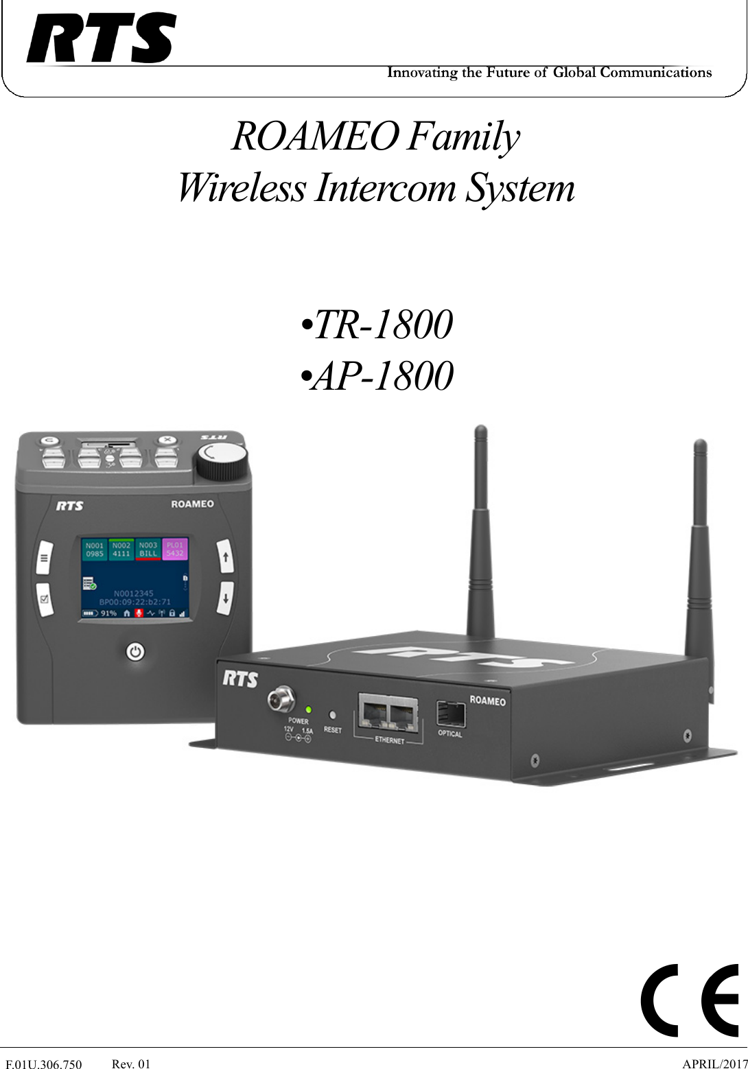
Bosch Security Systems M535 TR-1800 Beltpack User Manual F01U306750

Bosch Security Systems, Inc. TR-1800 Beltpack F01U306750

User Manual

 F.01U.306.750 Rev. 01 APRIL/2017ROAMEO Family Wireless Intercom System•TR-1800•AP-1800
Bosch Security Systems, Inc. Technical Manual  F.01U.306.750 Rev. 012   ROAMEO SystemPROPRIETARY NOTICEThe product information and design disclosed herein were origi-nated by and are the property of Bosch Security Systems, Inc. Bosch reserves all patent, proprietary design, manufacturing, repro-duction, use and sales rights thereto, and to any article disclosed therein, except to the extent rights are expressly granted to others.COPYRIGHT NOTICECopyright 2017 by Bosch Security Systems, Inc. All rights reserved. Reproduction, in whole or in part, without prior written permission from Bosch is prohibited.*All other trademarks are property of their respective owners.WARRANTY AND SERVICE INFORMATIONFor warranty and service information, refer to the appropriate web site below:RTS Intercoms .............................. www.rtsintercoms.com/warrantyRTS DigitalRTSTWAudioComWireless IntercomIntercom HeadsetsCUSTOMER SUPPORTTechnical questions should be directed to:Customer Service DepartmentBosch Security Systems, Inc.www.telex.comDECLARATION OF CONFORMITYThe full Declaration of Conformity may be found on the product page at www.rtsintercoms.com.TECHNICAL QUESTIONS EMEABosch Security Systems Technical Support EMEAhttp://www.rtsintercoms.com/contact_main.phpDISCLAIMERThe manufacturer of the equipment described herein makes no expressed or implied warranty with respect to anything contained in this manual and shall not be held liable for any implied warranties of fitness for a particular application or for any indirect, special, or consequential damages. The information contained herein is subject to change without prior notice and shall not be construed as an expressed or implied commitment on the part of the manufacturer.THE LIGHTNING FLASH AND ARROWHEAD WITHIN THE TRIANGLE IS A WARNING SIGN ALERTING YOU OF “DANGEROUS VOLTAGE” INSIDE THE PRODUCT.CAUTION: TO REDUCE THE RISK OF ELECTRIC SHOCK, DO NOT REMOVE COVER. NO USER-SERVICEABLE PARTS INSIDE. REFER SERVICING TO QUALIFIED SERVICE PERSONNEL.THE EXCLAMATION POINT WITHIN THE TRIANGLE IS A WARNING SIGN ALERTING YOU OF IMPORTANT INSTRUCTIONS ACCOMPANYING THE PRODUCT.SEE MARKING ON BOTTOM/BACK OF PRODUCT.WARNING: APPARATUS SHALL NOT BE EXPOSED TO DRIPPING OR SPLASHING AND NO OBJECTS FILLED WITH LIQUIDS, SUCH AS VASES, SHALL BE PLACED ON THE APPARATUS.WARNING: THE MAIN POWER PLUG MUST REMAIN READILY OPER-ABLE.CAUTION: TO REDUCE THE RISK OF ELECTRIC SHOCK, GROUNDING OF THE CENTER PIN OF THIS PLUG MUST BE MAINTAINED.WARNING: TO REDUCE THE RISK OF FIRE OR ELECTRIC SHOCK, DO NOT EXPOSE THIS APPARATUS TO RAIN OR MOISTURE.WARNING: TO PREVENT INJURY, THIS APPARATUS MUST BE SECURELY ATTACHED TO THE FLOOR/WALL/RACK IN ACCOR-DANCE WITH THE INSTALLATION INSTRUCTIONS.This product is AC and DC.
Bosch Security Systems, Inc. Technical ManualROAMEO System   3 F.01U.306.750 Rev. 01Important Safety Instructions1. Read these instructions.2. Keep these instructions.3. Heed all warnings.4. Follow all instructions.5. Do not use this apparatus near water.6. Clean only with dry cloth.7. Do not block any ventilation openings. Install in accordance with the manufacturer’s instructions.8. Do not install near any heat sources such as radiators, heat registers, stoves, or other apparatus (including amplifiers) that produce heat.9. Do not defeat the safety purpose of the polarized or grounding-type plug. A polarized plug has two blades with one wider than the other. A grounding type plug has two blades and a third grounding prong. The wide blade or the third prong are provided for  safety. If the provided plug does not fit into the outlet, consult an electrician for replacement of the obsolete outlet.10. Protect the power cord from being walked on or pinched particularly at plugs, convenience receptacles, and the point where they exit from the apparatus.11. Only use attachments/accessories specified by the manufacturer.12. Use only with the cart, stand, tripod, bracket, or table specified by the manufacturer, or sold with the apparatus. When a cart is used, use caution when moving the cart/apparatus combination to avoid injury from tip-over.13. Unplug this apparatus during lightning storms or when unused for long periods of time.14. Refer all servicing to qualified service personnel. Servicing is required when the apparatus has been damaged in any way, such as power-supply cord or plug is damaged, liquid has been spilled or objects have fallen into the apparatus, the apparatus has been exposed to rain or moisture, does not operate normally, or has been dropped.15. Do not disassemble or subject batteries to impact.16. Do not operate or charge a battery that has been damaged.17. Never heat the Li-Ion batteries or throw them into a fire.18. Charging the Li-Ion batteries in temperatures below freezing can cause permanent damage.19. Store the batteries in a cool, dry ventilated area.20. Dispose of Li-Ion batteries properly.21. Before flying with the ROAMEO system, consult the airline regulations concerning the Lithium batteries.22. Use only the manufacturer’s supplied charger to charge the batteries.
Bosch Security Systems, Inc. Technical Manual  F.01U.306.750 Rev. 014   ROAMEO System
TableofContentsBosch Security Systems, Inc. Technical Manual F.01U.306.750 Rev. 01Important Safety Instructions  ..............................................................................................................................3Chapter 1 : Certification Information ........................................................................................11FCC ....................................................................................................................................................... 11Industry Canada .................................................................................................................................... 12Europe ................................................................................................................................................... 13Chapter 2 : Introduction  .............................................................................................................15General Description .............................................................................................................................. 15Features  ................................................................................................................................................ 15Controls, Connections, and Specifications  ........................................................................................... 16TR-1800 Reference View ..................................................................................................................................16TR-1800 Connections ........................................................................................................................................17XLR - 5-Pin Female  .......................................................................................................................................173.5mm Auxiliary Jack   ...................................................................................................................................17Headset Mode ..............................................................................................................................................17USB Jack - Type A .........................................................................................................................................18Charging Jack  .................................................................................................................................................18TR-1800 Specifications  .....................................................................................................................................19AP-1800 Reference View ..................................................................................................................................20AP-1800 Connections ........................................................................................................................................21Dual Ethernet Connectors  ..............................................................................................................................21Fiber Optic Connector  ....................................................................................................................................21Power Connector  ............................................................................................................................................21Antenna Connector .........................................................................................................................................21AP-1800 Specifications  .....................................................................................................................................22Frequencies Of Operation .................................................................................................................... 23ETSI Defined RF Channels for DECT  ..............................................................................................................23
Bosch Security Systems, Inc. Technical Manual6   ROAMEO SystemRev. 01F.01U.306.750Chapter 3 : System Overview ......................................................................................................25System Description ................................................................................................................................25System Considerations  ................................................................................................................................... 25Access Points  .........................................................................................................................................26Home AP  ........................................................................................................................................................... 26Visitor AP .......................................................................................................................................................... 26Roaming .................................................................................................................................................27Home Connections  ............................................................................................................................................ 29Home to Visitor Roaming  ................................................................................................................................. 30System Drawings ....................................................................................................................................31Small System ..................................................................................................................................................... 31Medium System ................................................................................................................................................. 34Large System ..................................................................................................................................................... 36ROAMEO System Setup Checklist  .........................................................................................................38Chapter 4 : Site Survey  ...............................................................................................................39Description .............................................................................................................................................39Set Up Site Survey ..................................................................................................................................39Requirements ..................................................................................................................................................... 39Prepare the Hardware  ........................................................................................................................................ 39Set Up an Existing System with a Static IP Address  ..................................................................................... 40Add the Access Point to IPedit ....................................................................................................................... 43Assign the TR-1800 to an AP-1800 Channel ................................................................................................. 44Subscribe the TR-1800 to the AP-1800  ......................................................................................................... 44Set Up an Existing System with a Dynamic IP Address ................................................................................... 46Perform a Site Survey  ............................................................................................................................46Pre-conditions  ................................................................................................................................................... 46Description of Site Survey Screen  ................................................................................................................. 47Description of RSSI  ....................................................................................................................................... 47Description of QF ........................................................................................................................................... 48Notes ......................................................................................................................................................48Chapter 5 : Installation ...............................................................................................................49Access Point Placement .........................................................................................................................49Access Point Placement ..................................................................................................................................... 49Site Survey  ........................................................................................................................................................ 49RF (Radio Frequency) Considerations .............................................................................................................. 49Mounting Options .............................................................................................................................................. 50Antenna connection and placement  .................................................................................................................. 51Wall or Ceiling Mounting  .............................................................................................................................. 53Pole Mounting ................................................................................................................................................ 54Rail Mounting   ............................................................................................................................................... 54Free-Standing Installation  .............................................................................................................................. 55AP-1800 Mounting Surfaces  ............................................................................................................................. 56Power Over Ethernet  .............................................................................................................................57PoE Splitter Recommendation  .......................................................................................................................... 57Power Up the AP-1800 Access Point  ....................................................................................................58Connecting the Access Point to the Intercom  ........................................................................................59Configure the OMI using AZedit  ...................................................................................................................... 59Add the OMI to the Device Catalog in IPedit  ................................................................................................... 60Configure the OMI using IPedit ........................................................................................................................ 60Add the AP-1800 to IPedit  ................................................................................................................................ 61Configure the AP-1800 in IPedit ....................................................................................................................... 62
Bosch Security Systems, Inc. Technical Manual Rev. 01 ROAMEO System   7 F.01U.306.750Configure the Beltpack to its Home AP-1800  .................................................................................................. 65First Time Operation – Beltpack ...........................................................................................................66Battery Charge ................................................................................................................................................... 66Quick Charge  ................................................................................................................................................. 664-Bay LED Charge Status Description ....................................................................................................... 66In-Device Charging ........................................................................................................................................ 67Battery Installation and Removal ...................................................................................................................... 68Beltclip Installation and Removal  ..................................................................................................................... 69Subscribe the Beltpack and Connect to the Access Point  ................................................................................. 70Chapter 6 : Basic Operation ....................................................................................................... 73Intercom Keys and Displays  ..................................................................................................................73Key Assignment Types and Descriptions  ......................................................................................................... 73Color Display Descriptions for Intercom Keys ................................................................................................. 74Display Icons  .........................................................................................................................................75Operation of Buttons with Auto-Functions ............................................................................................81Adjusting the Volume .............................................................................................................................82Basic Intercom Key Operation ..............................................................................................................83Receiving a Call from an Assigned Alpha  ........................................................................................................ 83Making a Call to an Assigned Alpha  ................................................................................................................ 83Receiving a Call from an Unassigned Alpha  .................................................................................................... 83Making an Unassigned Call from the Belt Pack ............................................................................................... 84Call Waiting Window .............................................................................................................................85Unassigned caller calls, another unassigned caller calls  ................................................................................... 85Unassigned caller calls, an assigned caller calls  ............................................................................................... 85RSTP ......................................................................................................................................................85Scroll Lists  .............................................................................................................................................87Tally Flash  .............................................................................................................................................87Latching vs Momentary Key Operation .................................................................................................88Pages ......................................................................................................................................................88How to assign a call assignment to a button on the beltpack ............................................................................ 89Dark Mode  .............................................................................................................................................90How to activate Dark Mode  .............................................................................................................................. 90Lockout ...................................................................................................................................................90Scroll List Shortcut  ................................................................................................................................91Chapter 7 : Beltpack Overview ....................................................................................................................... 93System Quick Start .................................................................................................................................93Initial Beltpack Setup  ........................................................................................................................................ 93Button Operation – Common .................................................................................................................94Power On the Beltpack ...................................................................................................................................... 94Menu Structure – Main Menu Access  ....................................................................................................98Aux Input Menu  ................................................................................................................................................ 99AUX DIM Menu  ............................................................................................................................................... 99Volume Limit Menu ........................................................................................................................................ 100Headset Select Menu ....................................................................................................................................... 100Mic Gain .......................................................................................................................................................... 101Sidetone ........................................................................................................................................................... 102Mic Noise Gate ................................................................................................................................................ 102Hot Mic  ........................................................................................................................................................... 103Talk/Listen LED Buttons  ................................................................................................................................ 104
Bosch Security Systems, Inc. Technical Manual8   ROAMEO SystemRev. 01F.01U.306.750Front Display Brightness ................................................................................................................................. 104Top Display Brightness  ................................................................................................................................... 105LCD Timeout  .................................................................................................................................................. 105Call Tally Talk ................................................................................................................................................. 106Screen Flip ....................................................................................................................................................... 106Master Talk Switch  ......................................................................................................................................... 107Low Battery Alert ............................................................................................................................................ 108Call Waiting Alert  ........................................................................................................................................... 109DECT Connection Alert .................................................................................................................................. 109Matrix Connection Alert  ................................................................................................................................. 110Dark Mode Boot Alert ..................................................................................................................................... 111Key Clicks Alert .............................................................................................................................................. 112Alerts Levels .................................................................................................................................................... 112Key Assignments ..................................................................................................................................113How to assign a call assignment to a button on the beltpack  .......................................................................... 113System Setup  ................................................................................................................................................... 114Set Language  ................................................................................................................................................... 114Site Survey  ...................................................................................................................................................... 115Carrier Field  ................................................................................................................................................. 116Slot Field  ...................................................................................................................................................... 116AP ID Field  .................................................................................................................................................. 116RSSI Meter Display  ..................................................................................................................................... 116QF Meter Display ......................................................................................................................................... 116Diagnostics ...................................................................................................................................................... 117Access Point To Beltpack Icon  .................................................................................................................... 117Home Access Point Information  .................................................................................................................. 117Zone Mask Information ................................................................................................................................ 117Radio System Field  ...................................................................................................................................... 118CODEC Display ........................................................................................................................................... 118PMID Field ................................................................................................................................................... 118Software Update  .............................................................................................................................................. 118Alpha Size  ....................................................................................................................................................... 119Versions ........................................................................................................................................................... 120Icon Help ..............................................................................................................................................121Home Screen Menu  ......................................................................................................................................... 121Speaker Screen Menu ...................................................................................................................................... 121Brightness Screen Menu .................................................................................................................................. 121Alerts Screen Menu  ......................................................................................................................................... 121Key Assignments Screen Menu  ...................................................................................................................... 122System Setup Screen Menu ............................................................................................................................. 122Scroll List .............................................................................................................................................122Chapter 8 : Access Point Overview ..........................................................................................123AP-1800 Front Panel Description .......................................................................................................123Power LED ................................................................................................................................................ 124Reset Button .............................................................................................................................................. 124Ethernet Connection .................................................................................................................................. 124Optical Connection .................................................................................................................................... 124IPedit Requirements .............................................................................................................................124IPedit Main Window  ............................................................................................................................125Configuration ................................................................................................................................................... 128Device Name Field ....................................................................................................................................... 128Description Field .......................................................................................................................................... 128
Bosch Security Systems, Inc. Technical Manual Rev. 01 ROAMEO System   9 F.01U.306.750Version Field ................................................................................................................................................ 128IP Address Field ........................................................................................................................................... 128Netmask Field  .............................................................................................................................................. 129Gateway Address Field  ................................................................................................................................ 129DNS Server Field  ......................................................................................................................................... 129Domain Name Field  ..................................................................................................................................... 129MAC Address Field  ..................................................................................................................................... 129Use Static IP Settings Check Box  ................................................................................................................ 129Disable RSTP Check Box  ............................................................................................................................ 129Type Field  .................................................................................................................................................... 130Status Field ................................................................................................................................................... 130Sessions Field ............................................................................................................................................... 130AP Channels Field  ....................................................................................................................................... 130BP Channels Field ........................................................................................................................................ 131Sync Display Box ......................................................................................................................................... 131System ID Field  ........................................................................................................................................... 132PIN Field  ...................................................................................................................................................... 132Zone Drop Down Menu  ............................................................................................................................... 133CODEC Drop Down Menu .......................................................................................................................... 133AP ID Number Field  .................................................................................................................................... 133Sync Master Check Box ............................................................................................................................... 133Intercom Alpha Field  ...................................................................................................................................... 135Channel Description Field ............................................................................................................................... 135Destination Type Drop Down Menu ............................................................................................................... 135Destination Device Name Field (OMNEO devices and AP-1800 ROAMEO Access Point Only) ................ 135Destination IP Address Field ........................................................................................................................... 135Destination Description Field .......................................................................................................................... 135Destination Channel Drop Down Menu .......................................................................................................... 135Destination Channel Description Field  ........................................................................................................... 135Receiver Latency Field .................................................................................................................................... 136DECT BPID  .................................................................................................................................................... 136DECT Zone Selection Field  ............................................................................................................................ 136Chapter 9 : Maintenance .......................................................................................................... 137Access Point .........................................................................................................................................137Update Access Point Firmware  ....................................................................................................................... 137Create a System– Single Access Point ............................................................................................................ 138Create a System– Multiple Access Point  ........................................................................................................ 138Replace an Existing Access Point ................................................................................................................... 138IP Address of the Home Access Point Changes .............................................................................................. 139Add an Access Point to the System ................................................................................................................. 142Reboot the Access Point .................................................................................................................................. 142Access Point Reset – Factory Default or Normal ................................................................................144Factory Default Reset ...................................................................................................................................... 144Normal Reset ................................................................................................................................................... 144TBR-6 Test Mode ............................................................................................................................................ 145Beltpack ...............................................................................................................................................145Update the Firmware on the TR-1800 ROAMEO Beltpack ........................................................................... 145Add a Beltpack to the System  ......................................................................................................................... 146Update the Splash Screen on the TR-1800 ROAMEO Beltpack .................................................................... 146Beltpack Reset ......................................................................................................................................147Factory Reset ................................................................................................................................................... 147Settings Reset  .................................................................................................................................................. 147
Bosch Security Systems, Inc. Technical Manual10   ROAMEO SystemRev. 01F.01U.306.750Chapter 10 : Troubleshooting, Accessories and Replacements ..............................................149Troubleshooting ...................................................................................................................................149Accessories and Replacement Parts  ....................................................................................................155Notes ....................................................................................................................................................157
Bosch Security Systems, Inc. Technical Manual  F.01U.306.750 Rev. 01CHAPTER 1Certification InformationFCCThe RTS TR-1800 and AP-1800 devices are accepted under United States Federal Communication Commission Part 15. This device complies with Part 15 of the FCC. Operation is subject to the following two conditions:•This device may not cause interference.•This device must accept any interference, including interference that may cause undesired operation of the device.CAUTION: Changes or modifications made by the user could void the user’s authority to operate the equipment.The beltpack is intended to be worn on the belt of the user. Placing the beltpack in any other location on the body may reduce performance and void the user’s authority by the FCC to operate the equipment.This equipment has been tested and found to comply with the limits for a Class B digital device, pursuant to part 15 of the FCC Rules. These limits are designed to provide reasonable protection against harmful interference in a residential installation. This equipment generates, uses, and can radiate radio frequency energy and, if not installed and used in accordance with the instructions, may cause harmful interference to radio communications, However, there is no guarantee that interference will not occur in a particular installation. If this equipment does cause harmful interference to radio or television reception, which can be determined by turning the equipment off and on, the user is encouraged to try to correct the interference by one or more of the following measures:•Reorient or relocate the receiving antenna•Increase the separation between the equipment and receiver•Connect the equipment into an outlet on a circuit different from that to which the receiver is connected•Consult the dealer or an experienced radio/TV technician for help
12  Certification Information ROAMEO SystemBosch Security Systems, Inc. Technical Manual  F.01U.306.750 Rev. 01Mandatory Safety Instructions to Access Point Installers and Users. 1. Use only manufacturer or dealer supplied antennas. Antenna minimum safe distance, for an access point, as set by the FCC is 20 cm. Antenna gain: 3 dBi.2. The FCC (Federal Communications Commission) has adopted a safety standard for human exposure to RF (Radio Frequency) energy, which is below the OSHA (Occupational Safety and Health Administration) limits.3. To comply with current FCC RF Exposure limits, the antenna must be installed at or exceeding the minimum safe distance shown here, and in accordance with the requirements of the antenna manufacturer or supplier.4. Antenna substitution: Do NOT substitute any antenna for the one supplied by or recommended by the manufacturer or radio dealer. Substituting an antenna may expose a person or persons to harmful radio frequency radiation. Contact the radio dealer or the manufacturer for further instructions.WARNING: Maintain a separation distance from the antenna to person(s) of at least 20 cm.5. As the qualified end-user of this radio device, controlling the exposure conditions of bystanders to ensure that the minimum separation distance (above) must be maintained between the antenna and nearby persons to satisfy RF exposure compliance.Industry CanadaThe RTS TR-1800 and AP-1800 are certified to Industry Canada RSS-213 and ICES-003.This device complies with Industry Canada license exempt RSS standard(s). Operation is subject to the following two conditions: •This device may not cause interference, and •This device must accept any interference, including interference that may cause undesired operation of the device.Le présent appareil est conforme aux CNR d'Industrie Canada applicables aux appareils radio exempts de licence. L'exploitation est autorisée aux deux conditions suivantes: •l'appareil ne doit pas produire de brouillage, et •l'utilisateur de l'appareil doit accepter tout brouillage radioélectrique subi, même si le brouillage est susceptible d'en compromettre le fonctionnement.Industry Canada Compliance Statement . This Class B digital apparatus complies with Canadian ICES-003.Avis de conformité à la réglementation d'Industrie Canada . Cet appareil numérique de la classe B est conforme à la norme NMB-003 du Canada.
ROAMEO System Certification Information  13Bosch Security Systems, Inc. Technical Manual  F.01U.306.750 Rev. 01EuropeThis equipment is in compliance with the following directives;2011/65/EU RoHS Directive2012/19/EU WEEE Directive2014/53/EU RE D DirectivePlease dispose of the access point and beltpacks at the end of its operational life by taking it to the closest collection point or recycling center.This equipment is intended for use in professional audio intercom applications.Equipment intended for sale in (ISO 3166-1, 2 letter country code): AT, BE, BG, CH, CY, CZ, DE, DK, EE, ES, FI, FR, GB, GR, HR, HU, IE, IS, IT, LT, LU, LV, MT, NL, NO, PL, PT, RO, SE, SI, SK.A license may be required to operate this equipment in certain regions! Consult the national authority for possible requirements.The full EC Declaration of Conformity for the TR-1800 and AP-1800 may be found at the following website: www.rtsintercoms.com.
14  Certification Information ROAMEO SystemBosch Security Systems, Inc. Technical Manual  F.01U.306.750 Rev. 01
Bosch Security Systems, Inc. Technical Manual  F.01U.306.750 Rev. 01CHAPTER 2IntroductionGeneral DescriptionThe RTS ROAMEO system is an integrated digital wireless communications system consisting of beltpacks (TR-1800) and access points (AP-1800) communicating over DECT1. Communication between access points and the Matrix uses OMNEO technology, the Dante-based platform for high-quality audio over IP. DECT is a license-free standard, currently accepted in more than 80 countries worldwide.A large continuous radio coverage area can be created easily by strategic placement of access points. Beltpack users can roam freely within the coverage area without worry of losing communication.ROAMEO uses a standard IP infrastructure as a backbone, RTS recommends the exclusive use of managed switches through the IP network.Each TR-1800 ROAMEO beltpack is fully addressable and is conveniently programmed using the same software used in RTS wired keypanels.Features•Provides reliable, low latency communications between beltpacks and Matrix.•Provides roaming ability between access point locations with seamless communication.•User-selectable CODEC to allow the best audio quality or narrowband audio quality with double the number of users.•Uses DECT for RF path, a globally-accepted, license-free standard.•Ethernet backbone communications can be routed over existing LAN or WAN.•The beltpack provides a USB port for software upgrades and the download of custom front display graphics on boot.•Easy battery removal for bulk charging in a 4-bay battery charger or in-device charging.•Large color screen with easily recognizable icons for easy configuration and setup, and a smaller call waiting window located on top of the unit.•Designed with four (4) independent talk/listen keys for full-duplex communications, CWW (Call Waiting Window) functionality and one (1) XLR connector and one (1) 3.5mm connector for headset connections.•Site Survey feature facilitates initial placement of access points for optimal performance.1. Digital Enhanced Cordless Telecommunications
16  Introduction ROAMEO SystemBosch Security Systems, Inc. Technical Manual  F.01U.306.750 Rev. 01Controls, Connections, and SpecificationsTR-1800 Reference View1. Power button 2. Select button3. Main Menu button4. Color Backlit Display - 320 x 240 pixels5. Scroll Up Navigation button6. Scroll Down Navigation button7. Battery Release slide8. Removable Beltclip9. Volume knob/Selection button10. Call Waiting Clear button11. Talk/Listen Buttons: Four channel sets12. Talk/Listen indicator icons13. Call Waiting Reply button14. Call Waiting Monochrome Backlit Display – 128x32 pixels15. USB Connector- No charging, just data16. Headset Connector - standard 5-pin, female XLR connector17. Charge Jack - accepts a 5.5 mm x 2.5 mm plug with the center positive. Must be supplied with a 12VDC regulated power supply with at least 400 mA current capacity18. Auxiliary Input/Headset Connector – 3.5 mm connectorFIGURE 1. TR-1800 Reference View
ROAMEO System Introduction  17Bosch Security Systems, Inc. Technical Manual  F.01U.306.750 Rev. 01TR-1800 ConnectionsXLR - 5-Pin FemaleIMPORTANT: Most XLR headsets use dynamic-type microphones that work well with radiated RF energy. However, some XLR headsets use Electret microphones that are susceptible to RF energy and may generate audio noise. Always test any Electret type headsets with the product before using to troubleshoot any issues.3.5mm Auxiliary Jack Accepts a 3.5mm TRS (Tip, Ring, Sleeve) stereo connector or a mono TS (Tip, Sleeve)NOTE: Audio can be input via the Tip, Ring 1 or both.Headset ModeAccepts 3.5mm iPhone-like TRRS (Tip, Ring 1, Ring 2, Sleeve) connectorFIGURE 2. XLR – 5-pin Female ConnectionPin Description1Ground2 Microphone3 Headphone +4 Headphone -5 Headphone - (tied to pin 4)FIGURE 3. 3.5 mm Tip, Ring, Sleeve diagramDescriptionTip Audio InputRing 1 Audio InputRing 2 GroundSleeve Not ConnectedDescriptionTip Headphone -Ring 1 Headphone +Ring 2 GroundSleeve Microphone (+5VDC bias supplied)
18  Introduction ROAMEO SystemBosch Security Systems, Inc. Technical Manual  F.01U.306.750 Rev. 01USB Jack - Type ACharging JackAccepts a 5.5mm x 2.5mm plug with positive centerPin Description1 +5 (only powered in firmware download process)2 Data-3 Data +4 GNDDescriptionCenter Accepts 12VDCShell GND
ROAMEO System Introduction  19Bosch Security Systems, Inc. Technical Manual  F.01U.306.750 Rev. 01TR-1800 SpecificationsGeneral:Audio ModesG.722 wideband modeG.726 narrowband modeFrequency Response (G.722)165 Hz – 7.0 kHzFrequency Response (G.726)255 Hz – 3.6 kHzFront Backlit DisplayColor, 320 x 240 pixel, QVGA LCDTop Backlit DisplayBlack and White, 128 x 32 pixel LCDRemovable Battery PackLi-Ion Pack, 7.5 VDC, 2300 mAhrTypical Battery Life17 hoursEnvironmental:Operating Temperature32°F – 122°F (0°C – 50°C)Storage Temperature-4°F – 158°F (-20°C – 70°C)Dimensions (w/beltclip)4.93 in. H x 4.00 in. W x 2.31 in. D(12.51 cm H x 10.16 cm W x 5.87 cm D)Dimensions (w/o beltclip)4.93 in. H x 4.00 in. W x 1.85 in. D(12.51 cm H x 10.16 cm W x 4.70 cm D)Weight (w/ battery)0.771 lbs. (350 g)Weight (w/o battery)0.507 lbs. (230 g)Controls:Level ControlsTop-mounted rotary encoderIndividual listen adjustmentTalk/Listen Control4 x Talk and 4 x Listen buttons (top panel)Number of Assignment Pages4Call Waiting ControlReply and Clear buttonsMenu Settings ControlMenu, Set, Up, and Down buttonsConnections:Headset ConnectorsXLR-5F3.5mm (iPhone type)Headphone Impedance (both XLR and 3.5mm)51 – 2000 Microphone Type (XLR Jack)Dynamic or Electret auto-detectMicrophone Type (3.5mm Jack)Electret only (+5V bias always supplied)In-beltpack Charging JackAccepts 2.5 x 5.5mm charging plug, positive centerIn-beltpack Charging Jack Voltage/Current12VDC @ 400mAAuxiliary Audio Input Jack3.5mm for MP3 type audio inputOnly fed to local headsetFirmware Update JackUSB Type ARF Communications:Frequency Range1880 – 1900 MHz (EU - Europe, Asia, and Australia)1920 – 1930 MHz (NA - North America)Communication ProtocolDECTCarrier Frequency SelectionAutomatic via DCS (Dynamic Channel Selection)ModulationGFSKMaximum Output Power (Peak)200 mW (EU)100 mW (NA)Average Power (G.722 wideband)17 mW (EU)Average Power (G.726 narrowband)8 mW (EU)Average Power (G.722 wideband)8 mW (NA)Average Power (G.726 narrowband)4 mW (NA)TR-1800 Beltpack Case (includes removable and adjustable shoulder strap)Dimensions4 in. x 1.5 in. x 4.5 in.(101.6 mm x 38.1 mm x 114.3 mm)CertificationsRoHS, FCC part 15D, FCC part 15B, FCC/IC Class B device, IC RSS-213, IC ICES-003, CE, EN 301 406, EN 301 489-6, EN 60950-1, RCM, Singapore, Mexico
20  Introduction ROAMEO SystemBosch Security Systems, Inc. Technical Manual  F.01U.306.750 Rev. 01AP-1800 Reference View1. Mounting Tabs2. Mounting Holes (for use with optional Clamp Kit)3. Power Connector4. Power LED Indicator (for more information, see “AP-1800 Specifications” on page 22)5. Reset Button6. Ethernet Connector (x2)7. Optical Connector (Accepts small form factor pluggable SFP modules)8. Antenna (x2)FIGURE 4. AP-1800 Reference View
ROAMEO System Introduction  21Bosch Security Systems, Inc. Technical Manual  F.01U.306.750 Rev. 01AP-1800 ConnectionsDual Ethernet ConnectorsFiber Optic ConnectorAccepts small Form Factor Pluggable (SFP) transceivers•SM (Single Mode) SFP Module (F.01U.278.502)•MM (Multi Mode) SFP Module (F.01U.278.503)Power ConnectorAccepts a screw-on, locking 5.5mm x 2.5mm x 13.8mm plug with positive center.Center – Accepts 12VDC @ 1.5AShell – GNDAntenna ConnectorReverse-polarity SMA Female Jack (R-SMA-F)Pin Description1 Data 1 +2 Data 1 - 3 Data 2 +4 Data 3 +5 Data 3 -6 Data 2 -7 Data 4 +8 Data 4 -
22  Introduction ROAMEO SystemBosch Security Systems, Inc. Technical Manual  F.01U.306.750 Rev. 01AP-1800 SpecificationsGeneral:Audio ModesG.722 widebandG.726 narrowbandMax. beltpacks per AP-1800 (G.722)5Max. beltpacks per AP-1800 (G.726)10ConnectivityStandard 100Base-T or GigE EthernetProtocol Running on EthernetOMNEOEthernet Cabling RequiredUTP CAT-5e or betterPower Supply TypeExternal DC, Wall WartPower Supply Input100–240 VAC, 50–60 Hz, 0.6APower Supply Output (AP-1800 Input)12VDC @ 1.5A, positive centerEnvironmentalOperating Temperature32°F – 122°F (0°C – 50°C)Storage Temperature-4°F – 158°F (-20°C – 70°C)Dimensions5.17 in. H x 7.67 in. W x 1.52 in. D(13.13 cm H x 19.47 cm W x 3.86 cm D)Weight (w/antennas)0.992 lbs. (450 g)Weight (w/o antennas)0.893 lbs.(405 g)Connections:Ethernet Connectors2 x Standard RJ-45 JacksOptical ConnectorAccepts small form factor pluggable SMP modulesRF ConnectorsReverse-SMA-FRF Communications:Frequency Range1880-1900 MHz (EU - Europe, Asia, Australia)1920-1930 MHz (NA - North America)Communication ProtocolDECTCarrier Frequency SelectionAutomatic via DCS (Dynamic Channel Selection)ModulationGFSKPowerMaximum Output Power (Peak)200mW (EU)100mW (NA)Average Power, load dependent (G.722, wideband)17-83mW (EU)Average Power, load dependent (G.726, wideband)8-83mW (EU)Average Power, load dependent (G.722, wideband)8-42mW (NA)Average Power, load dependent (G.726, narrowband)4-42mW (NA)Antenna - ElectricalFrequency1850-1990MHzGain3dBiHorizontal Beam Width360°Impedance50 OhmMax. Power50WVSWR<2:1PolarizationLinear - along length of antennaAntenna - MechanicalWeight0.77 oz (22g)Length5.2 in. (133mm)Max. Diameter0.52in. (13.2mm)FinishMatte BlackConnectorReverse Polarity SMA PlugOperating Temperature-40°F to 131°F (-40°C to 55°C)AP-1800 CertificationsRoHS, FCC Part 15D, FCC Part 15B, FCC/IC Class B device, IC RSS-213, IC ICES-003, CE, EN 301 406, EN 301 489-6, EN 60950-1, RCM, Singapore, Mexico
ROAMEO System Introduction  23Bosch Security Systems, Inc. Technical Manual  F.01U.306.750 Rev. 01Frequencies Of Operation1880 – 1900 MHz (Europe)1920 – 1930 MHz (North America) ETSI Defined RF Channels for DECTDECT systems automatically select the best interference-free frequencies on which to operate. Users do not need to do any frequency coordination. The ETSI (European Telecommunications Standards Institute) Channel Plan (Table 1) shows the European and North American RF carrier pools the DECT systems use. There are 10 frequencies in Europe and five frequencies in North America.* ETSI (European Telecommunications Standards Institute)** Most common carriers used in the worldTABLE 1. ETSI* defined RF Channels for DECTRF Carrier Number Carrier Frequency, MHz Where Used0 1897.344** Europe, Singapore, Australia1 1895.616** Europe, Singapore, Australia2 1893.888** Europe, Singapore, Australia3 1892.160** Europe, Singapore, Australia4 1890.432** Europe, Singapore, Australia5 1888.704** Europe, Singapore, Australia6 1886.976** Europe, Singapore, Australia7 1885.248** Europe, Singapore, Australia8 1883.520** Europe, Singapore, Australia9 1881.972** Europe, Singapore, Australia23 1921.536 US, Canada, Mexico24 1923.264 US, Canada, Mexico25 1924.992 US, Canada, Mexico26 1926.720 US, Canada, Mexico27 1928.448 US, Canada, Mexico
24  Introduction ROAMEO SystemBosch Security Systems, Inc. Technical Manual  F.01U.306.750 Rev. 01
Bosch Security Systems, Inc. Technical Manual  F.01U.306.750 Rev. 01CHAPTER 3System OverviewSystem DescriptionA ROAMEO wireless intercom system consists of two types of devices: a wireless beltpack (TR-1800) and an access point(AP-1800).The ROAMEO system can be configured for anything from small systems (one access point and a few beltpacks) to a large system (10 access points and up to 40 beltpacks). The ROAMEO system provides quality, configurable wireless audio across the coverage area and is easily expandable.The typical indoor coverage area varies widely depending on the installation area. The typical range of an access point is between 50–100 meters.System Considerations•Number of access points required for coverage area.•Sufficient access point coverage overlap to allow seamless roaming for beltpacks.•The number of access points to provide sufficient capacity for all beltpacks planned to be in the area. It is especially important to consider the number of beltpacks that are booted in the same area (and then moved to other areas). The initial beltpack staging area should be able to provide access to all devices.•Area Considerations• Metal Barriers -  Signal reflects off metal which can provide good signal fill for areas; however, the signal will not pass through metal.• Cement -  Signal usually passes through with little problem. Dependent on the cement thickness and the presence of any metal rebar.• Wood and Drywall -  No issues.• Overall Size -  May need more access points to cover a large area even if only a few beltpacks are used.• Spectrum Bandwidth -  Other DECT systems in the area (i.e., wireless phone systems use some of the DECT spectrum allowing less beltpacks in the area).•Matrix system supports enough OMNEO channels for the amount of beltpacks.•Ethernet infrastructure supports access points with sufficient bandwidth for additional traffic and uses managed switches (OSI Layer 3 capable).
26  System Overview ROAMEO SystemBosch Security Systems, Inc. Technical Manual  F.01U.306.750 Rev. 01Access PointsThe ROAMEO AP-1800 converts DECT signaling to the OMNEO protocol, Audinate’s Dante digital high-quality audio transport over IP. AP-1800 units are physically connected via the Ethernet network to an ADAM or ADAM-M matrix using an OMI card1. The OMI card maintains a bi-directional OMNEO channel for each beltpack. The AP-1800 acts as the interface between the OMI card and the beltpack communicating via DECT.There are two types of access points in a ROAMEO system:•Home AP•Visitor APHome APThe Home AP is any AP-1800 that configures the beltpack’s BPID (Beltpack ID) to one of its available OMNEO channels using IPedit.Visitor APThe Visitor AP is any AP-1800 that does not configure the BPID to one of the its OMNEO channels in IPedit. The Visitor AP can be thought of as a bridge that allows the visiting beltpack to communicate within the system while outside of its Home AP radius (Figure 6).NOTE: The Home and Visitor labels are in reference to the beltpack. A beltpack’s Home access point could be a Visitor access point to a different beltpack.1. For more information on OMI, see the OMI manual at www.rtsintercoms.comFIGURE 5. Components of a ROAMEO System
ROAMEO System System Overview  27Bosch Security Systems, Inc. Technical Manual  F.01U.306.750 Rev. 01RoamingThe ROAMEO system allows beltpacks to move between the radio coverage area of one AP-1800 to the radio coverage area of another AP-1800. This is called roaming. Roaming is monitored and maintained by the system of access points, making it transparent to the user. Handoff from one coverage area to another is done in such a way to make it nearly seamless. Roaming does not involve any processing on the OMI, allowing the OMNEO bit stream to be completely uninterrupted.In order for seamless hand-off to occur, the AP-1800 RF coverage area must overlap. This allows the beltpack handoff commands to be sent to both the current access point and the new access point in the coverage area which ensures a seamless hand-off.The 80 RSSI (Received Signal Strength Indicator) contour line shown in Figure 6 is a number related to the access point’s RF signal strength as received at the beltpack. This can be measured using the beltpack’s site survey screen when testing an access point location. For more information, see “Site Survey” on page 39.IMPORTANT: When there is little or no coverage overlap, a beltpack can experience undesirable audio break-up before the hand-off to a new access point occurs.When access points boot, they scan the area and pick an RF carrier and time slot based upon the other beacons detected in the area. The access points also avoid using carriers and time slots already in use by using AP IDs (access point identification). Each access point in a system has to be set to a unique AP ID using the IPedit application. An algorithm based upon the AP ID of the access point forces access points to never select the same carrier and slots. In high density beltpack areas where more than six wideband access points may be required, some access points may not detect an RF carrier already in use, that can result in roaming issues. The system works best if these scenarios are avoided by designing high density areas with good access point overlap. Figure 7 shows how all seven access points can detect and coordinate carriers and time slots with each other, even when there are more than six devices present. The 112 RSSI contour line can be measured by a beltpack using the site survey screen when testing an access point location. See “Perform a Site Survey” on page 46.FIGURE 6. SimpleFigure 6 Roaming Diagram
28  System Overview ROAMEO SystemBosch Security Systems, Inc. Technical Manual  F.01U.306.750 Rev. 01IMPORTANT: It is important if more than six wideband or ten narrowband access points are used to cover the same area that all the access point be placed in a location where they can detect each other.FIGURE 7. High Density Roaming
ROAMEO System System Overview  29Bosch Security Systems, Inc. Technical Manual  F.01U.306.750 Rev. 01Home ConnectionsIMPORTANT: When configuring home connections, remember to assign the configured access point channels to the OMI card in the Matrix (see “Connecting the Access Point to the Intercom” on page 59).Each access point channel is a bi-directional OMNEO channel for audio, command, and control with the matrix. For a wideband system (CODEC G.722), there are five access point channels available to assign BPIDs. For a narrowband system (CODEC G.726), there are 10 access point channels available. The OMNEO channel that returns to the OMI from the Home access pointFIGURE 8. Home Access Point to Matrix System Drawing
30  System Overview ROAMEO SystemBosch Security Systems, Inc. Technical Manual  F.01U.306.750 Rev. 01Home to Visitor RoamingWhen a beltpack roams from its Home AP to a Visitor AP, a new OMNEO connection is made between both access points. However, before the new connection’s OMNEO channel is used, the new DECT RF connection must be confirmed as good. The new DECT RF connection is made before breaking from the old connection. This means the existing DECT RF link to the Home AP is maintained until the new DECT RF link to the Visitor AP is confirmed. When the connection is confirmed, the existing DECT RF link is dropped and the new OMNEO channel from the Visitor AP is used.FIGURE 9. Home Access Point to Visitor Access Point Roam System Drawing
ROAMEO System System Overview  31Bosch Security Systems, Inc. Technical Manual  F.01U.306.750 Rev. 01System DrawingsThese following drawings are basic examples of small, medium and large ROAMEO systemsSmall SystemFIGURE 10. Small System – G.722 Coverage for a Remote Area
32  System Overview ROAMEO SystemBosch Security Systems, Inc. Technical Manual  F.01U.306.750 Rev. 01FIGURE 11. Small System – G.726 Coverage for a Single Area
ROAMEO System System Overview  33Bosch Security Systems, Inc. Technical Manual  F.01U.306.750 Rev. 01FIGURE 12. Small System – G.722 Coverage over Two Areas
34  System Overview ROAMEO SystemBosch Security Systems, Inc. Technical Manual  F.01U.306.750 Rev. 01Medium SystemFIGURE 13. Medium System – G.722 Coverage Over Two Areas and Between
ROAMEO System System Overview  35Bosch Security Systems, Inc. Technical Manual  F.01U.306.750 Rev. 01FIGURE 14. Medium System – G.726 Coverage Over One Large Area
36  System Overview ROAMEO SystemBosch Security Systems, Inc. Technical Manual  F.01U.306.750 Rev. 01Large SystemFIGURE 15. Large System – G.722 Coverage Over Three Areas
ROAMEO System System Overview  37Bosch Security Systems, Inc. Technical Manual  F.01U.306.750 Rev. 01FIGURE 16. Large System – G.726 Coverage Over One Large Area
38  System Overview ROAMEO SystemBosch Security Systems, Inc. Technical Manual  F.01U.306.750 Rev. 01ROAMEO System Setup Checklist❐Each beltpack has only one HOME access point.❐Each system can have only one Sync Master access point (set in IPedit).❐When subscribing a beltpack to the system, the beltpack must be within 40 feet (12 meters) of an access point in that system.❐Each access point set to the G.722 CODEC can be a host for up to five beltpacks (no channels left for roaming beltpacks).❐Recommend each G.722 access point only be loaded to four beltpacks to allow for roaming beltpacks.❐Each access point set to the G.726 CODEC can be host for up to 10 beltpacks (no channels left for roaming beltpacks).❐Recommend each G.726 access point only be loaded to eight beltpacks to allow for roaming beltpacks.❐If the CODEC is changed for a system, the beltpacks must be subscribed again.❐A system can only have all G.722 or all G.726 access points (no CODEC mixing is allowed).❐Always have Ethernet connected to an access point before powering up the access point.❐The Ethernet network follows standard Ethernet practices.❐Use only CAT5e UTP or better Ethernet cable.❐Use only Layer 3 IP routing-capable, managed switches.❐100Mbit networks can only have up to seven hops (A link between the Matrix and an Ethernet switch counts as a hop, each link after daisy chaining through an access point counts as a hop).❐1GBit networks can only have up to 20 hops (A link between the Matrix and an Ethernet switch counts as a hop, each link after daisy chaining through an access point counts as a hop).❐Maximum system size is 10 access points and 40 beltpacks.❐The overlap RF coverage area between two adjacent access points should have an RSSI reading of 80 or better from each access point for error free roaming.❐In a high density beltpack coverage area with more than six access points (G.722) or more than 10 access points (G.726) covering the area, all access points must be within each other’s -70dBm RF coverage contour (112 or better on the beltpack’s RSSI site survey screen).❐If a PoE adapter is used, access points cannot be daisy-chained. Only one access point can be powered from the PoE adapter. For more information, see “Power Over Ethernet” on page 57.
Bosch Security Systems, Inc. Technical Manual  F.01U.306.750 Rev. 01CHAPTER 4Site SurveyDescriptionSite Survey is the application (standard on the TR-1800) used to plan and design the ROAMEO system. Site survey provides crucial information on roaming coverage. With the ROAMEO site survey application, finding coverage areas for access points, even when obstacles are encountered, such as metal walls, reinforced concrete, metal-coated glass, etc. is easier to accomplish.There are two ways to perform a site survey:•With a Static IP Address•With a Dynamic IP AddressSet Up Site SurveyWith a simple setup, site survey can be used and evaluated.RequirementsRequired equipment for a simple setup:•AP-1800 access point and power supply•TR-1800 beltpack and battery•Computer with an Ethernet port and IPedit software application installed•Standard Ethernet cablePrepare the Hardware1. Install the antennas on the access point (see “Antenna connection and placement ” on page 51).2. If performing a site survey without a matrix, use an Ethernet cable to connect the AP-1800 to the computer.ORIf performing a site survey with a matrix, use an Ethernet cable to connect the AP-1800 to the network.
40  Site Survey ROAMEO SystemBosch Security Systems, Inc. Technical Manual  F.01U.306.750 Rev. 01Set Up an Existing System with a Static IP AddressTo set the computer to a Link Local IP Address, do the following:IMPORTANT: These instructions detail a typical setup for the Windows 7 platform.NOTE: If the AP-1800 has been connected to a Matrix system in the past or assigned a static IP Address already, then assigning the computer a Link Local Address will not work. If the AP-1800’s IP Address is known, configure the computer to be in its network. If the IP Address is unknown, then reset the AP-1800 back to a Link Local Address by performing a factory reset, see “Factory Default Reset” on page 144.1. From the Start menu, select Control Panel.2. Click Network and Internet.The Network and Internet window appears.
ROAMEO System Site Survey  41Bosch Security Systems, Inc. Technical Manual  F.01U.306.750 Rev. 013. Click Network and Sharing Center.The Network and Sharing Center window appears.4. Click Change Adapter Settings.The Network Connections window appears.5. Double-click Local Area Connection.The Local Area Connection Status window appears.
42  Site Survey ROAMEO SystemBosch Security Systems, Inc. Technical Manual  F.01U.306.750 Rev. 016. Click Properties.The Local Area Connection Properties window appears.7. From the connection list, select Internet Protocol Version 4 (TCP/IPv4).
ROAMEO System Site Survey  43Bosch Security Systems, Inc. Technical Manual  F.01U.306.750 Rev. 018. Click the Properties button.The Internet Protocol Version 4 (TCP/IPv4) Properties window appears.9. Select the Use the following IP Address check box.The IP fields become active.10. In the IP Address: field, enter 169.254.0.1.11. In the Subnet mask: field, enter 255.255.0.0.12. Click the OK button to exit the Internet Protocol Properties window. 13. Click the Close button to exit the Local Area Connection Properties window.Add the Access Point to IPeditTo add the access point to IPedit, do the following:1. Power on the access point.When the power light turns solid green, the access point is ready.2. Open IPedit.
44  Site Survey ROAMEO SystemBosch Security Systems, Inc. Technical Manual  F.01U.306.750 Rev. 013. From the Device menu, select Add.The Add Devices window appears.4. Select the access point (displays as the device type OAP-5 or OAP-10).5. Click Add.The access point appears in the Device Catalog in the left pane.6. Click Done.Assign the TR-1800 to an AP-1800 ChannelTo assign the TR-1800 to an AP-1800 channel, do the following:1. From the Device Catalog on the left, select the AP-1800.The Device Information fields populate.2. Select the Sync Master check box to set the AP-1800 to Sync Master.IMPORTANT: On a piece of paper, note the 3-digit System ID (the default is B2B) and the 4-digit PIN (the default is 0000) of the access point. These are used later to subscribe the beltpack to the access point.3. Power up the TR-1800.The BPID displays on the front panel. This is a 10-digit, hexadecimal number (for example, 00:09:22:B5:21). 4. In the DECT BPID field, enter the beltpack ID to assign to that channel.5. From the Changes menu, select Send All.The Send Changes window appears.6. Click OK.The changes are sent to the AP-1800 and then it resets. After approximately one minute, the Sync check box turns green. The AP-1800 stores the BPID, even if power is disconnected (for example, in non-volatile memory).Subscribe the TR-1800 to the AP-1800To subscribe the TR-1800 to the AP-1800, do the following:IMPORTANT: Be sure the beltpack is within 40 feet (12 meters) of the AP-1800.1. With the AP-1800 running, power up the TR-1800.The front color display panel activates.2. Press the Menu button.The beltpack main menu appears.
ROAMEO System Site Survey  45Bosch Security Systems, Inc. Technical Manual  F.01U.306.750 Rev. 013. Using the up and down arrow buttons, navigate to the System Setup icon.4. Press the Select button.The Subscription Setup screen appears with the system setup icon highlighted.5. Press the Select button.The Enter system ID screen appears.NOTE: If the beltpack had been subscribed to an access point previously, the last system ID used populates the screen. The default System ID is B2B.6. Using the up and down buttons, enter the first character of the access point system ID.7. Press the Select button.The focus moves to the next character space in the system ID.8. Repeat steps 8 and 9 until the system ID is entered completely.9. Once the system ID is entered, press the Select button.The Enter PIN screen appears.10. Using the up and down buttons, enter the first digit of the access point pin number (The default is 0000).11. Press the Select button.The focus moves to the next character space in the system ID.12. Repeat steps 12 and 13 until the system ID is entered completely.The Home screen appears in the front display, the DECT connection icon  and the RSSI indication icon  become active.
46  Site Survey ROAMEO SystemBosch Security Systems, Inc. Technical Manual  F.01U.306.750 Rev. 01Set Up an Existing System with a Dynamic IP AddressIMPORTANT: The computer should be set to obtain an IP Address automatically. The DHCP server for the matrix must be enabled in the AZedit application before the computer delivers an IP Address.To connect the AP-1800 to the matrix, do the following:1. Using an Ethernet cable, connect the AP-1800 to the Matrix directly or via a network switch.2. Connect one end of the power supply to the AP-1800 and the other end to the wall outlet.The AP-1800 powers on.3. Using IPedit, configure the OMI card with the AP-1800 unit.NOTE: If the AP-1800 being used is already part of an operating system and a TR-1800 is subscribed to it, then no more IP configuration is required. Turn off all other AP-1800 devices in the system so coverage of the single access point being tested can be found. For more information, see “Perform a Site Survey” on page 46.For complete instructions on how to configure the AP-1800, see “Connecting the Access Point to the Intercom” on page 59.Perform a Site SurveyA site survey is performed to determine the placement of access points to ensure RF coverage of the desired area. A beltpack, communicating with an access point at a test location, is set to the site survey screen where RSSI (Received Signal Strength Indication) and QF (Quality Factor) are both used to find the RF coverage area. Pre-conditions •A beltpack has been successfully subscribed to an access point. •A site map or blueprint of the building that can be marked up. •Power can be supplied to the access point at the possible test locations either by using power extension cables or battery power. For battery power, 12VDC @ 0.600 Amps must be available to the access point. A charged 12VDC battery rated for at least 2.4 Amp-hours is recommended for a typical site survey length of time. The input connector required for an access point is a 13.8mm long, female barrel, 2.5mm x 5.5mm connector. IMPORTANT: The unit is marked 1.5 Amps. This is an upper limit set to handle peak loads when fully loaded. When doing site surveys, an access point is not heavily loaded. To perform a site survey, do the following: 1. Place the access point in the location to be tested for coverage.2. Power up the access point.When the power light turns to solid green, the access point is ready. 3. Power up the beltpack.The splash screen momentarily displays and then the home screen appears. NOTE: When the beltpack finishes booting, the home screen of the beltpack indicates a wireless connection . If the wireless connection does not display, verify settings in the “Setup for a Site Survey” section. 4. Press the Menu button.The beltpack main menu appears.
ROAMEO System Site Survey  47Bosch Security Systems, Inc. Technical Manual  F.01U.306.750 Rev. 015. Using the up and down arrow buttons, navigate to the System Setup icon. 6. Press the SELECT button. The beltpack system setup menu appears. 7. Using the up and down arrow buttons, navigate to the Site Survey icon. 8. Press the SELECT button.The site survey screen appears. Description of Site Survey ScreenDescription of RSSICARRIER - Current RF carrier of the access point (this may change from time to time)SLOT -  Current time slot on the RF carrier the access point to beltpack packets are on (this may change from time to time)AP ID -  Access Point IdentificationRSSI -  Radio Signal Strength IndicationQF -  Quality Factor. This is representative of the number of packets received out of packets sentRSSI Color Description0-47 Red Weak - poor to no reception in area48-70 Yellow Marginal - some dropouts of audio in the area71-216 Green Strong - good RF coverage
48  Site Survey ROAMEO SystemBosch Security Systems, Inc. Technical Manual  F.01U.306.750 Rev. 01Description of QF9. Mark the access point’s location on the building layout diagram.10. Walk around with the beltpack throughout the area(s) of interest while looking at the site survey screen.NOTE: Record the RSSI and QF number on the building layout diagram at several locations throughout the area of interest.NOTE: When enough data points are collected, draw a line on the building layout, using the coverage limits. If surveying for roaming coverage, take note access point coverage is shown in Figure 6 on page 27.Notes•Try other access point locations to improve the RF coverage in the desired area, if needed.•If setting up a roaming system, ensure a good overlap of coverage areas of the access points. Good roaming between access point areas requires overlap of coverage for error free roaming.•The access points that support roaming beltpacks should have an RSSI of >80 from each access point involved in the overlap to provide error free roaming. See Figure 6 on page 27.•In high beltpack density areas, where more than six access points on wideband (G.722) or more than 10 access points on narrowband (G.726) are required to provide coverage over the same area due to a larger number of beltpacks, it is important the access points are located in good RF coverage of each other. In these scenarios, the access points need to be within -70 dBm of each other. This translates to each access point should be in a coverage area with an RSSI reading of 112 or better on a site survey. See Figure 7 on page 28.QF Color Description0-4 Red Weak - too many dropouts in the area5-6 Yellow Marginal - some dropouts of audio in the area7-10 Green Strong - good RF coverageGOOD COVERAGE AREA DEFINITIONRSSI = 71-216, Site survey bar in the green.QF = 7-10, Site survey bar in the green.If the two indications are different, always use the worst case of the RSSI and QF indication for defining a good coverage area. Example: QF =10 and RSSI=71, use the RSSI level as the cutoff for the good coverage area.
Bosch Security Systems, Inc. Technical Manual  F.01U.306.750 Rev. 01CHAPTER 5InstallationAccess Point PlacementConsiderations•Access Point Placement•System Considerations - See System Drawings Chapter•Mounting Options•Mounting Surfaces•Site SurveyAccess Point PlacementThe placement of access points can be critical for optimal RF performance of the system. When positioning the access points, place them in the best location for maximum, unimpeded coverage of the area. Installation of the access point should be high, above the area of interest, on a truss or ceiling. Tilt the antennas so they are approximately 15° to 30°. The access point could also be placed high on a vertical wall; in this case, the antennas should pointing straight up.Site SurveyFor more information, see “Site Survey” on page 39.RF (Radio Frequency) ConsiderationsKeep antennas away from metal, as metal can detune them and distort the RF pattern. It is recommended to keep the antennas at least 2λ (2 * wavelength) from any parallel metal object (about 30 cm/12 inches), not including metal trusses or metal roofs. A metal roof, metal trusses, or the access point’s metal case become a reflector, offering advanced coverage by reflecting the RF signal down to the intended area of coverage, which can improve coverage. Note, when mounting to drywall, be aware of metal studs that can affect signal quality. Metal in walls can greatly attenuate or even block RF signals. In the case of a metal wall, it may become necessary to place another access point on the other side of the wall if continued coverage is desired.The polarization of the access point antennas should match the polarization of the beltpack’s internal antennas when worn on the belt. The standard position of the antennas are vertical. This means the electrical field of the antennas is also vertical. For best reception, the access point’s antennas should be in the vertical position, either straight up or straight down.
50  Installation ROAMEO SystemBosch Security Systems, Inc. Technical Manual  F.01U.306.750 Rev. 01Mounting OptionsThere are four recommended ways to mount the ROAMEO AP-1800 access point unit:•Wall or ceiling mount•pole mount•rail mount•free-standing installation (such as a table or shelf) – not shown aboveIMPORTANT: The mounting clamp kit, for rail or pole mounting, is sold separately.FIGURE 17. Mounting Options
ROAMEO System Installation  51Bosch Security Systems, Inc. Technical Manual  F.01U.306.750 Rev. 01Antenna connection and placement Antennas should be in the upright-most position for the best reception of signal. The antenna has a joint to adjust the angle, if needed. To attach the antennas to the ROAMEO AP-1800, do the following: 1. Gently push the antenna into the antenna connector on the ROAMEO AP-1800. Take care to align the connector pin with the antenna pin hole. 2. Turn the antenna clockwise to tighten in place. NOTE: For permanent antenna installation, we recommend tightening the antennas so they cannot come loose from vibration or if bumped. Hand-tighten the antenna, then using needle-nose pliers, grasp the serrated metal collar of the antenna and tighten about 1/16th inch (1.6 mm) more in the clockwise direction. This tightens the connector to about 5 lbf-in (0.56 Nm), the specification for a solid connection.
52  Installation ROAMEO SystemBosch Security Systems, Inc. Technical Manual  F.01U.306.750 Rev. 01To adjust the antennas for the best signal reception when the access point is mounted horizontally, do the following:  > Carefully bend the antenna 90° at the antenna joint until the antennas are aligned straight up or down.
ROAMEO System Installation  53Bosch Security Systems, Inc. Technical Manual  F.01U.306.750 Rev. 01Wall or Ceiling MountingTo wall mount the ROAMEO AP-1800 access point, do the following: 1. Using the access point and a pencil, mark the four hole locations on the wall or ceiling.NOTE: It may be necessary to predrill the holes or use screw anchors, depending on the material of the wall. 2. Align the AP-1800 in the position and placement desired. 3. Using a screw driver, drive the screws into the predefined holes.
54  Installation ROAMEO SystemBosch Security Systems, Inc. Technical Manual  F.01U.306.750 Rev. 01Pole Mounting To pole mount the ROAMEO AP-1800 access point, do the following: 1. Align the mounting clamp in the pole use position on the bottom of the AP-1800. 2. Using the supplied screws from the mounting kit, attach the mounting clamp to the AP-1800. 3. Fit the mounting clamp around the pole desired. 4. Once in position, use the adjustment knobs to tighten the clamp around the pole.  Rail Mounting To rail mount the ROAMEO AP-1800 access point, do the following: 1. Align the mounting clamp in the rail use position on the bottom of the AP-1800.
ROAMEO System Installation  55Bosch Security Systems, Inc. Technical Manual  F.01U.306.750 Rev. 012. Using the supplied screws from the clamp kit, attach the mounting clamp to the AP-1800. 3. Fit the mounting clamp around the rail. 4. Once in position, use the larger adjustment knob to tighten the clamp around the pole. Free-Standing InstallationSetting the AP-1800 unit on a table or shelf is commonly referred to as free-standing installation. When free-standing installation the AP-1800, it is important to remember to position the antenna perpendicular to the unit (antenna in the air) for the best signal reception.
56  Installation ROAMEO SystemBosch Security Systems, Inc. Technical Manual  F.01U.306.750 Rev. 01AP-1800 Mounting SurfacesThe ROAMEO AP-1800 Access Point can be mounted to many different surfaces. Using Table 2, determine the proper mounting surface and mounting materials needed.TABLE 2. Mounting Surfaces and MaterialsMounting Surface Materials Used QtyDrywallDrywall screws 4Drywall anchors (as needed) 41/4-inch (max.) Flat washer (as needed) 4Concrete1/4-inch (max.) Concrete screws 4Concrete anchors (as needed) 41/4-inch (max.)Flat washer (as needed) 4Wood1/4-inch (max.) Wood Screws  41/4-inch (max.) Flat washer (as needed) 4Metal Surface1/4-inch (max.) Sheet metal screws 41/4-inch (max.) Flat washer (as needed) 4OR1/4-inch (max.) Self-tapping or Self-drilling sheet metal screws 4OR1/4-inch (max.) Machine Screw 4Machine nut or drilled and tapped holes1/4-inch (max.) Flat washer (as needed) 4Rack Frame10-32 Rackmount Screws 2 to 41/4-inch (max.) Flat washer (as needed) 2 to 4OR10-32 Truss Head Rackmount Screws 2 to 4Building Structure Member (roof trusses, etc)1/4-inch (max.) U-bolts 41/4-inch (max.) Flat washers 41/4-inch (max.) Machine nuts 4ORSee Metal Surface Mounting
ROAMEO System Installation  57Bosch Security Systems, Inc. Technical Manual  F.01U.306.750 Rev. 01Power Over EthernetThe access point is tolerant of PoE (Power Over Ethernet) voltages on the Ethernet network, but cannot be powered by PoE directly without an add-on accessory kit (see “Accessories and Replacement Parts” on page 155). The add-on accessory kit can be used when combined with an existing PoE (802.3af) or PoE+ (802.3at) managed Ethernet switch to provide power to the access point from the Ethernet network. Only one access point can be powered by this regulated Ethernet PoE splitter, due to the power consumption of the access points.PoE Splitter RecommendationOutput PowerRegulated 12VAC @ 1AmpPower CableMost splitters have a 2.1 by 5.5mm terminated cable, however, for the AP-1800 input a long barrel 2.5x5.5mm connector with the length of 13.8mm is requiredPoE TypePoE (IEEE 802.3af) and/or PoE+ (IEEE 802.3at)Ethernet Port1000Mbps Auto-Negotiating type
58  Installation ROAMEO SystemBosch Security Systems, Inc. Technical Manual  F.01U.306.750 Rev. 01Power Up the AP-1800 Access PointTo connect and configure the access point to the matrix, do the following:1. Using an Ethernet cable or an optical fiber cable, connect the access point to the Matrix via a network switch.NOTE: Either Ethernet port can be used. IMPORTANT: To use the fiber option on the AP-1800,. you must have the optional SFP fiber module installed. For ordering information, see “Accessories and Replacement Parts” on page 155.2. Connect one end of the power supply to the AP-1800 and the other end to the wall outlet.The AP-1800 powers on.NOTE: The connection to the access point should be screwed on tight for a locked connection.
ROAMEO System Installation  59Bosch Security Systems, Inc. Technical Manual  F.01U.306.750 Rev. 01Connecting the Access Point to the IntercomThe OMI card is configured using AZedit and IPedit; however, only IPedit can be used to configure the access point.IMPORTANT: Verify the computer is connected to the same network as the Intercom Matrix frame.Configure the OMI using AZeditTo configure the OMI to the Access Point using AZedit, do the following:1. From the Status menu in AZedit, select I/O Cards.The I/O Card Status window appears showing a list of installed cards.2. Right-click the OMI card to configure to the AP-1800.A pop-up menu appears.3. From the pop-up menu, select OMNEO Configuration.The OMNEO Configuration window appears.4. From the OMNEO card drop down menu, select the slot number where the OMI card is located in the frame.The device Name field auto-populates with the name of the device.5. From the Local Channel drop down menu, select the channel to use to communicate to the AP-1800 across the network.NOTE: Channels not already configured to connect to another device appear with an asterisk (*) next to them.6. In the Partner Device Name field, enter the name of the AP-1800 to communicate with or select the Browse icon to select from a list of devices.ORIn the Partner IP Address field, enter the IP Address of the device to make a connection. This field auto-populates when the Device Name is selected.7. From the Partner Device Type drop down menu, select the type of device to which the OMI card is connecting.8. From the Partner Channel drop down menu, select the channel on the device to which the OMI communicates.9. When finished, click Apply.Apply sends all the changes to all the cards in the intercoms or click Cancel to discard all the changes made.
60  Installation ROAMEO SystemBosch Security Systems, Inc. Technical Manual  F.01U.306.750 Rev. 01Add the OMI to the Device Catalog in IPeditTo add the OMI to IPedit, do the following:1. Open IPedit.2. From the Device menu, select Add.The Add Devices Window appears, open to the Search tab.3. Select the OMI card.The Add button becomes active.4. Click the Add button.The OMI card appears in the device catalog in the left panel.5. Click the Done button.The Add Devices window closes.Configure the OMI using IPeditTo configure the OMI using IPedit, do the following:Using the Device Configuration and Status Pane1. In the Device Name field, enter the device name.Initially, OMI cards are given a default name.IMPORTANT: Changing the device name causes the device to reboot. It is not necessary to change the device name. However, if changed, it is best to do this early in the setup so revisiting other devices that connect to this device and updating them later is not necessary.2. In the Description field, enter a description for the OMI card, if desired.Using the Channel Configuration and Status Pane3. In the Channel Description field, enter a channel description, if applicable.4. From the Destination Type drop down menu, select OAP-5 or OAP-10.NOTE: The Destination Type does not need to be selected if using the Browse window to select the device. It fills the Type and IP Address automatically. The type is either OAP-5 (OMNEO Access Point - 5 Channel) or OAP-10 (OMNEO Access Point - 10 Channel) depending on the CODEC configured on the device.5. In the Destination Device Name field, enter the name of the device to which the channel will connect.ORClick the ... button.The Discovered Devices Window appears.a. Expand the tree to view the destination devices available.b. From the expanded tree, select the destination device.c. Click OK.6. From the Destination Channel drop down menu, select the channel to which the OMI will connect.7. Send the changes to the OMI.
ROAMEO System Installation  61Bosch Security Systems, Inc. Technical Manual  F.01U.306.750 Rev. 01Add the AP-1800 to IPedit1. Start IPedit.2. From the Devices menu, select Add.The Add Devices window appears.3. From the Available Devices pane, select the Access Point.The Add button becomes active.4. Click Add.The AP-1800 appears in the device catalog in the left panel.5. Click Done.The Add Devices window closes. The AP-1800 appears in the Device Catalog.
62  Installation ROAMEO SystemBosch Security Systems, Inc. Technical Manual  F.01U.306.750 Rev. 01Configure the AP-1800 in IPeditTo configure the Access Point with IPedit, do the following:IMPORTANT: The user must be signed in to IPedit with network administrator rights to complete these instructions.1. From the Device Catalog on the left, select the AP-1800. The Device Information pane populates.2. In the Description field, enter a unique description for the access point.3. In the Version field, verify the version information is correct.4. Verify the IP Address is correct, if using a Static IP Address.5. Select the Disable RSTP check box to disable the RSTP protocol, if desired.DECT Information6. In the System ID field, enter the system ID for the access point. This field accepts a 3-digit hexadecimal number. By default, this field is set to B2B.NOTE: All access points in a system must have the same System ID.7. In the AP ID field, enter the unique AP ID for the access point. The range for this field is 1–254.8. Select the Sync Master check box if the access point is the master for the entire system.NOTE: There can be only one master in each system.
ROAMEO System Installation  63Bosch Security Systems, Inc. Technical Manual  F.01U.306.750 Rev. 019. In the PIN field, enter the PIN of the access point. By default, this field is set to 0000.10. From the Zone drop down menu, select the zone the access point is assigned. By default the zone is set to 011. From the CODEC drop down menu, select the CODEC the access point is running.IMPORTANT: The CODEC of the access point is either G.722 (wideband) or G.726 (narrowband) A system MUST be all G.722 or all G.726Channel Configuration Pane12. From the column headings, select the channel to configure (for example, Channel 1, etc).IMPORTANT: With CODEC G.722, five channels are available for configuration.With CODEC G.726, 10 channels are available for configuration.TIP: When setting up a multiple access point system, consider leaving one or two channels open for additional beltpacks and distribute the existing beltpacks equally among the access points.13. In the Channel Description field, enter a channel description, if applicable.14. From the Destination Type drop down menu, select the OMI card to which the channel is connected.
64  Installation ROAMEO SystemBosch Security Systems, Inc. Technical Manual  F.01U.306.750 Rev. 0115. In the Destination Device Name field, enter the name of the OMI card to which the channel is connected.ORClick the browse button.The Discovered Devices window appears.a. Expand the tree to view the available destination devices.b. From the expanded tree, select the destination device.c. Click OK.The Discovered Devices window closes.16. From the Destination Channel drop down menu, select the destination channel to which the channel is connected.17. In the DECT BPID, enter the beltpack ID to assign to that channel.NOTE: For information on obtaining the beltpack ID, see “Configure the Beltpack to its Home AP-1800” on page 65.18. In the DECT Zone Selections field, enter the zone the beltpack is permitted to operate in (the default is zone one).ORFrom the DECT Zone drop down menu, select the check box next to each zone to assign to the beltpack.NOTE: At least one zone must be selected for the beltpack. Any combination of zones may be selected.19. From the Changes menu, select Send.20. From the File menu, click Save.
ROAMEO System Installation  65Bosch Security Systems, Inc. Technical Manual  F.01U.306.750 Rev. 01Configure the Beltpack to its Home AP-1800To assign a beltpack to an access point channel, do the following:1. From the Device Catalog on the left, select the AP-1800. The Channel Configuration populates.2. Power up the beltpack.The BP ID displays on the front panel. This is a 10 digit, hexadecimal number in the format of: BP00:09:XX:XX:XX.3. In the DECT BPID, enter the beltpack ID to assign to that channel.4. From the Changes menu, select Send Changes.The Send Changes window appears. 5. Click OK.The changes are sent to the access point. The AP stores the BPID even if power is disconnected.
66  Installation ROAMEO SystemBosch Security Systems, Inc. Technical Manual  F.01U.306.750 Rev. 01First Time Operation – Beltpack Battery ChargeCharging the battery for the TR-1800 beltpack can be done two different ways.•Quick Charge Charging via the CHG-240 4-bay battery charger•In-Device ChargingQuick ChargeCharging the battery in the 4-bay quick charger requires about 2.5 hours to completely charge a fully discharged battery. Once charging is complete, the batteries may be left on the charger indefinitely.4-Bay LED Charge Status DescriptionIn addition to the power light, the 4-bay charger has two LED indicator lights to notify of the charging status. The following LED indicators include:Solid Yellow Charging in progressFlashing Yellow Analyzing Battery / Fault detectedSolid Green Charging is completeTo quick charge the batteries, do the following:1. Ensure the TR-1800 is powered off and remove the battery. See “Battery Installation and Removal” on page 68.2. Plug the 4-bay battery charger into a standard AC wall outlet.3. Insert the battery into one of the battery slots on the charger.The LED in front of the battery slot indicates the charge status.4-BayQuick ChargeChargerLEDIndicators
ROAMEO System Installation  67Bosch Security Systems, Inc. Technical Manual  F.01U.306.750 Rev. 01In-Device ChargingThe TR-1800 is also capable of charging the battery while the battery is still installed in the beltpack. It takes approximately eight hours to fully charge a completely discharged battery.NOTE: The CH 4 talk button on the top of beltpack indicates the charge status.The following charge status indicators include:Red Charging in progressGreen Charging is completeTo charge the battery in the beltpack, do the following:1. Power off the beltpack.2. On the bottom of the beltpack, attach the power cable to the charge connector.3. Plug the wall charger of the power cable into a standard AC wall outlet.IMPORTANT: Operation of the beltpack while charging the battery is not supported.
68  Installation ROAMEO SystemBosch Security Systems, Inc. Technical Manual  F.01U.306.750 Rev. 01Battery Installation and RemovalTo install the battery in the beltpack, do the following:1. Align the battery with the battery slot on the beltpack.2. Carefully slide the battery into the slot until it clicks in place (3).To remove the battery from the beltpack, do the following:1. Verify the beltpack is powered off.2. Slide the battery release button down to release the battery pack (1).3. Slide the battery pack out of the beltpack (2).FIGURE 18. Battery Installation and Removal213
ROAMEO System Installation  69Bosch Security Systems, Inc. Technical Manual  F.01U.306.750 Rev. 01Beltclip Installation and RemovalTo install or remove the beltclip, do the following: > On the back panel of the TR-1800 beltpack, align and slide the beltclip into the beltclip track to install the beltclip (1).A click is felt/heard when the beltclip is securely in place.OROn the back panel of the TR-1800 beltpack, while lifting up on the tension clip up, carefully slide the beltclip out of the beltclip track (2).FIGURE 19. Installation and Removal of the TR-1800 Beltclip12TensionClip
70  Installation ROAMEO SystemBosch Security Systems, Inc. Technical Manual  F.01U.306.750 Rev. 01Subscribe the Beltpack and Connect to the Access PointIMPORTANT: An access point must be configured using IPedit before a beltpack can be subscribed with a system.To subscribe the beltpack, do the following:1. Press the power button to turn the beltpack on.An unsubscribed beltpack powers up with the System Setup screen appears.NOTE: A subscribed beltpack can access this setup screen through the beltpack menus. For more information, see “Subscribe the TR-1800 to the AP-1800” on page 44.2. From the System Setup screen, press the SELECT button on the front of the beltpack.The system ID screen appears.NOTE: If it becomes apparent that no access points can be found, the MENU key may be used to return to the System Setup screen to try again.3. Using the UP and DOWN buttons, enter the first digit of the System ID.4. Press the SELECT button.The focus moves to the next field in the system ID.NOTE: The SELECT button advances the focus to the next field. The MENU button goes back one field.5. Repeat step 3 and step 4 until the system ID is entered.6. Press the SELECT button.The beltpack begins scanning for active access points with its RF coverage area. The search process can take several seconds. When an access point is found, the PIN entry screen displays.
ROAMEO System Installation  71Bosch Security Systems, Inc. Technical Manual  F.01U.306.750 Rev. 01NOTE: The PIN number default is all zeroes.7. Using the UP and DOWN buttons, change the first PIN digit field. NOTE: The SELECT button advances the focus to the next field. The MENU button goes back one field.8. Press the SELECT button.The focus moves to the next field.9. Repeat step 7 and step 8 until the PIN is entered.10. After entering the four digit PIN, press the SELECT button.The beltpack/access point subscription process begins. This process can last several seconds.•If the subscription is successful, the beltpack displays the main operating screen.•If the subscription is unsuccessful, an appropriate error message is displayed.IMPORTANT: Once a beltpack is subscribed it requests a startup packet from the digital matrix. Beltpack subscription is only required for new beltpacks, or when making changes to the intercom system. A subscribed beltpack can be turned off and on, its battery changed, etc. without re-subscribing.On power-up, a subscribed beltpack displays a splash screen, and then switches to the main operating screen. It may take several minutes (depending on the size of the system) to download the start-up packets from the digital matrix. Once downloaded, the talk/listen icons on the screen are populated with key assignments.
72  Installation ROAMEO SystemBosch Security Systems, Inc. Technical Manual  F.01U.306.750 Rev. 01
Bosch Security Systems, Inc. Technical Manual  F.01U.306.750 Rev. 01CHAPTER 6Basic OperationIntercom Keys and DisplaysKey Assignment Types and DescriptionsPP = Point to Point (call from one port to another)PL = Party Line (talk/listen to a party line)IFB = Interrupt Foldback (interrupt program input to talk to output)SL = Special List (call a group of panels)RY = Relay (activate a relay)ISO = Camera Isolate (private call)UR = UPL Resource (trigger a UPL statement)IFBSL = IFB Special List (call multiple IFBs)GRP = Group Call (call a group of panels, collapse to private call)AD = Auto Dial (dial a TIF)
74  Basic Operation ROAMEO SystemBosch Security Systems, Inc. Technical Manual  F.01U.306.750 Rev. 01Color Display Descriptions for Intercom KeysThe TR-1800 front displays uses key colors to distinguish the type of key assignment programmed for each key. Use Table 3 to help determine the available key assignment colors.TABLE 3. Default Color KeysDefault Color DescriptionBright Green Listen IndicatorBrown IFB Special ListTeal Point-to-PointDark Yellow ISOLight Blue UnassignedPale Yellow  Special FunctionsMagenta RelayPink Party LineSalmon IFB, Talk IndicatorPale Green Special ListPeriwinkle UPL Resource
ROAMEO System Basic Operation  75Bosch Security Systems, Inc. Technical Manual  F.01U.306.750 Rev. 01Display IconsIMPORTANT: Located in the beltpack menu structure is an internal help menu to help define the icons used on the beltpack.Table 4: Icon DescriptionsIcon Icon Name DescriptionHome ScreenHome Screen The Home Screen icon is a navigational marker indicating home screen is displayed.Battery Gauge The Battery Gauge icon is used to indicate the amount of battery life left on the beltpack. This icon, along with the percentage of battery life, is found in the lower left corner of the beltpack display window.Hot Mic The Hot Mic icon is used to indicate when the hot mic is enabled. When the hot mic is enabled, audio from the mic goes out to the Matrix without regard to the talk key state. When active, the icon appears on the Home screen. When the hot mic is disabled, no icon is shown.DECT Connection The DECT Connection icon is used to indicate the beltpack has a DECT connection. This icon appears on the Home screen.The inner DECT ring on the icon represents a DECT Connection, while the outer DECT ring represents that 2-way communication is established between the beltpack and access point. The yellow dot on the right indicates the beltpack is transmitting packets, while the green dot on the left indicates the beltpack is receiving packets.Matrix Connected The Matrix Connected icon is used to indicate the beltpack is connected to the matrix.Function Lockout The Function Lockout icon is used to indicate when a lock is engaged on the functions of the beltpack. For more information, see “Lockout” on page 90.RF Signal The RF Signal icon is used to indicate the RF signal strength the beltpack is receiving.Scroll List The Scroll List icon indicates a scroll list is available to scroll through available callers.For more information on scroll lists, see “Scroll Lists” on page 87.Scroll List Not LoadedThe Scroll List Not Loaded icon indicates there are no scroll lists loaded.Page(s) The Page icon indicates the page of assignments currently displayed. There are four pages of assignments available for configuration on the beltpack.For more information, see “Pages” on page 88.
76  Basic Operation ROAMEO SystemBosch Security Systems, Inc. Technical Manual  F.01U.306.750 Rev. 01Screen Flip The Screen Flip icon is used to flip the orientation of the front display screen for easy viewing when the beltpack is clipped to pants or a belt. Use the up and down arrow buttons to navigate to the flip screen icon in the page list. Select the page flip by pressing the select button.NOTE: Orientation of the front display can be changed using the menu. For more information, see “Screen Flip” on page 106.Menu Screen The Menu Screen icon is used to enter the Main menu. From this menu, audio levels, microphones types, display brightness, alert notifications, and key assignments can be configured. Certain system setup functions, such as subscribing the beltpack to the system, setting the language of the beltpack, performing a site survey, viewing diagnostic information, and updating the beltpack firmware can be accessed from this menu.For more information, see “Menu Structure – Main Menu Access” on page 98.Menu ScreenSpeaker Settings The Speaker Settings menu is used to access configuration options for Aux Input Level, Aux Override Level, Volume Limit, Max Audio Volume Limit, and Headset Select.For more information, see “Speaker Settings” on page 99.Microphone The Microphone menu is used to access configuration options for mic gain, sidetone adjustments, mic noise gate, and hot mic enable/disable. For more information, see “Mic Menu” on page 101.Brightness The Brightness menu is used to access configuration options for the different display brightness options for the top panel button LED intensity, Color LCD brightness, CWW LCD brightness, LCD timeout, tally light settings, flip screen and master talk mode.For more information, see “Brightness” on page 104.Audio Alerts The Audio Alerts menu is used to access configuration options for the different audio alerts such as low battery, call waiting, DECT connection, matrix connection, audio alert level, dark mode boot, and key clicks.For more information, see “Alerts” on page 108.Key Assignments The Key Assignments menu is used to create, edit and delete key assignments for the beltpack. For more information, see “Press and hold the MENU button to exit the menu.” on page 112.System Setup The System Setup menu is used to access system function options for the beltpack. For more information, see “System Menu” on page 114Icon Help The Icon Help menu is used to access a listing of the different definitions for the various icons used on the beltpack.For more information, see “Icon Help” on page 121.Table 4: Icon DescriptionsIcon Icon Name Description
ROAMEO System Basic Operation  77Bosch Security Systems, Inc. Technical Manual  F.01U.306.750 Rev. 01Scroll List The Scroll List menu is used to access the different scroll lists available. Scroll lists make searching for particular key assignments easier by grouping the assignments by type.For more information, see “Scroll List” on page 122.Audio SetupAux Input Level The Aux Input Level menu is used to adjust the volume of the input audio heard in the headset. For more information, see“Aux Input Menu” on page 99.Aux Override LevelThe Aux Override Level menu item is used to configure the amount to decrease the aux volume when another call is received. For more information, see “AUX DIM Menu” on page 99.Max Audio Volume LimitThe Max Audio Volume Limit menu item is used to configure the maximum output volume allowed by the beltpack. For more information, see “Volume Limit Menu” on page 100.Headset Select The Headset Select menu item is used to select the headset connector being used with the beltpack. For more information, see “Headset Select Menu” on page 100.Headset XLR The Headset XLR icon indicates the headset is attached to the XLR connector on the beltpack. For more information on how to configure the headset connection, see “Headset Select Menu” on page 100.Headset on Aux The Headset AUX icon indicates the headset is attached to the AUX connector on the beltpack. For more information on how to configure the headset connection, see “Headset Select Menu” on page 100.Mic SetupMic Gain The Mic Gain menu item is used to set the amount of gain of the headset mic. For more information, see “Mic Gain” on page 101.Sidetone Adjust The Sidetone Adjust menu item is used to set the level of sidetone in the headset. For more information, see “Sidetone” on page 102.Mic Noise Gate The Mic Noise Gate menu it is used to set the microphone activation level. For more information, see “Mic Noise Gate” on page 102.Hot Mic The Hot Mic menu item is used to turn the Hot Mic function on or off. For more information, see “Hot Mic” on page 103.Table 4: Icon DescriptionsIcon Icon Name Description
78  Basic Operation ROAMEO SystemBosch Security Systems, Inc. Technical Manual  F.01U.306.750 Rev. 01Backlights and LEDsLED Intensity The Talk/Listen LED menu item is used to configure the LED brightness of the Talk and Listen LEDs. For more information, see “Talk/Listen LED Buttons” on page 104.Front Display BrightnessThe Front Display Brightness menu item is used to set the brightness of the front display. For more information, see “Front Display Brightness” on page 104Top Display BrightnessThe Top Display Brightness menu item is used to set the brightness of the top display. For more information, see “Top Display Brightness” on page 105.LCD Timeout The LCD Timeout menu item is used configure the LCD timeout on the beltpack.For more information, see “LCD Timeout” on page 105Call Tally Talk The Call Tally Talk menu item is used to turn the talk LED flashing off or on for an incoming key assigned call. For more information, see “Call Tally Talk” on page 106.Screen Flip The Screen Flip menu item is used to flip the orientation of the front display screen. This helps to better see the display without having to take the beltpack off. For more information, see “Screen Flip” on page 106.Master Talk The Master Talk menu item is used to enable one-touch talk activation. This option is used to configure the push button function of the volume encoder knob to activate all talk function buttons. For more information, see “Master Talk Switch” on page 107.Audio AlertsLow Battery Alert The Low Battery Alert menu item is used to enable or disable a tone alert heard when a low battery is detected. For more information, see “Low Battery Alert” on page 108.Call Waiting Alert The Call Waiting Alert menu item is used to enable or disable a tone alert heard when a call is received in the call waiting window queue.For more information, see “Call Waiting Alert” on page 109.MatrixConnection AlertThe Matrix Connection Alert menu item is used to enable or disable a tone alert heard when the matrix connection cannot be found. For more information, see “Matrix Connection Alert” on page 110.Audio AlertVolumeThe Audio Alert Volume menu item is used to set the audio level of the alerts tones.Table 4: Icon DescriptionsIcon Icon Name Description
ROAMEO System Basic Operation  79Bosch Security Systems, Inc. Technical Manual  F.01U.306.750 Rev. 01No DECTConnectionThe No DECT Connection menu item is used to enable or disable a tone alert heard when there is no DECT connection present.Dark Mode Boot AlertThe Dark Mode Boot Alert menu is used to enable or disable a tone alert heard when the beltpack is finished booting and is ready to use or is about to shut off. For more information, see “Dark Mode Boot Alert” on page 111.Key Click Alert The Key Clicks Alert menu is used to enable or disable a tone alert heard when a button is pressed or tapped. For more information, see “Key Clicks Alert” on page 112.Key AssignmentsAssigned Alpha The Assigned Alpha menu item is used to assign alphas to specific keys on the beltpack. For more information, see “How to assign a call assignment to a button on the beltpack” on page 113.Listen Key AssignedThe Listen Key Assigned appears when the key has been assigned as a listen assignment.Talk Key Assigned The Talk K ey Assigned icon appears when the key has been assigned as a talk assignment.Alpha Page 1..4 The Alpha Page displays the page number of the page currently being displayed. There are four configurable pages where key assignments of frequently used contacts can be added.For more information, see “Pages” on page 88.System FunctionsSystem Setup  The System Setup menu is used to subscribe the beltpack to the AP-1800. For more information, see “System Setup” on page 114.Set Language The Set Language menu is used to set the language the beltpack displays. For more information, see “Set Language” on page 114.Site Survey The Site Survey menu is used to view site survey information. For more information, see “Site Survey” on page 39.Diagnostics The Diagnostics menu is used to display the beltpack’s configuration, such as RSSI strength, Access Point RF channel, time slot, the IP Address of the access point, the CODEC the beltpack is currently using, etc. For more information, see “Diagnostics” on page 117.Table 4: Icon DescriptionsIcon Icon Name Description
80  Basic Operation ROAMEO SystemBosch Security Systems, Inc. Technical Manual  F.01U.306.750 Rev. 01Software Update The Software Update menu is used to perform software updates on the beltpack. For more information, see “Software Update” on page 118. Ver s Th e  Vers menu displays the software version currently in the beltpack.Test The Te st menu displays an option for running tests on the beltpack.Access Point This Access Point icon represents an access point seen in the diagnostics display screen.Beltpack This Beltpack icon represents a beltpack seen in the diagnostics display screen.Alpha The Alpha menu is used to select the length of alpha allowed on the beltpack. Available options are: 4 character, 6 character, 8 character, and 8 character unicode.Table 4: Icon DescriptionsIcon Icon Name Description
ROAMEO System Basic Operation  81Bosch Security Systems, Inc. Technical Manual  F.01U.306.750 Rev. 01Operation of Buttons with Auto-FunctionsOperation of keys with auto-functions, is as follows:Talk+auto-follow Talk and listen can be activated separately. The listen assignment listens to whatever is assigned to the talk button.Talk+auto-listen Both talk and listen activates when talk is activated.Talk+auto-mute Listen turns off when talk is activated.Talk+auto-reciprocal Listen is always on and talk may be turned on or off.Talk+auto-table If an IFB talk button has an auto-table listen assignment, talk and listen is independently activated. The listen key listens to whatever is defined as the IFB Listen Source for the IFB assigned to the talk key.All Call Activating this button activates all buttons to the left of it, up to, but not including another all call key.Talk+DIM If a point-to-point key has the DIM function as a level 2 talk assignment, activating the button causes the crosspoint levels to diminish for any other intercom ports currently listening to the same destination and are in the same DIM tables.
82  Basic Operation ROAMEO SystemBosch Security Systems, Inc. Technical Manual  F.01U.306.750 Rev. 01Adjusting the VolumeTo adjust the volume on the beltpack, do the following:1. On the top panel of the beltpack, turn the volume dial clockwise to increase the volume.ORTurn the volume dial counter-clockwise to decrease the volume.A progression bar appears in the front and top displays showing increases and decreases in volume.
ROAMEO System Basic Operation  83Bosch Security Systems, Inc. Technical Manual  F.01U.306.750 Rev. 01Basic Intercom Key OperationReceiving a Call from an Assigned AlphaWhen a call comes into the beltpack from a keypanel assignment that already has a key assigned on the beltpack, the front panel alpha starts flashing as well as the Talk LED button on the top panel that corresponds with the keypanel key in the front panel display. To answer a call from an assigned alpha, do the following: > On the top panel of the beltpack, tap the flashing talk LED button.NOTE: Audio is heard as soon as the Talk LED button starts flashing, even though the corresponding Talk LED button has not been pressed.Making a Call to an Assigned AlphaTo make a call, do the following: > On the top panel of the beltpack, tap the Talk LED button that corresponds with the keypanel assignment displayed in the front panel display screen.A red talk bar appears on the talk assignment displayed in the front color display.To release a call, do the following: > On the top panel of the beltpack, tap the Talk LED button that corresponds with the alpha displayed in the front panel display screen.A red talk bar disappears from the talk assignment displayed in the front color display.Receiving a Call from an Unassigned AlphaUnassigned alphas are calls that have not been assigned a key on the beltpack. When a call comes to the beltpack from an unassigned alpha, the assignment displays in the call waiting window and an audio chirp is heard in the headset.For more information, see “Call Waiting Window” on page 85.To receive a call from a non-assigned alpha, do the following: > When a non-assigned alpha calls the beltpack, press and hold the reply button to answer.As long as the button is held, the audio is heard by the non-assigned caller.NOTE: Audio is heard as soon as the CWW displays the caller’s alpha.IMPORTANT: All non-assigned calls and callers must use push-to-talk. Push-to-talk is done by pressing the Reply button when wanting to talk.To release a call from an unassigned alpha, do the following: > When finished, press the Clear button on the top panel of the beltpack.
84  Basic Operation ROAMEO SystemBosch Security Systems, Inc. Technical Manual  F.01U.306.750 Rev. 01Making an Unassigned Call from the Belt PackTo make a call to a non-assigned alpha, do the following:1. From the Home screen, press the MENU button.The Main Menu appears in the beltpack display screen.2. Using the arrow buttons, navigate to the Scroll List icon. 3. Press the Select button.A list of assignment types appear on the beltpack display screen.4. Using the arrow buttons, scroll to the desired assignment type.5. Press the Select button.A list of available assignments appear in the beltpack display screen.6. Using the arrow buttons, scroll to the assignment ID desired.7. Press the Select button.The alpha appears in the call waiting window display.8. Press and hold the REPLY button to initiate the call.The call is made. The selected assignment ID appears in the call waiting window.NOTE:  As long as the REPLY button is held, the audio is sent to the beltpack being called.9. When finished, press the Clear button on the top panel of the beltpack.
ROAMEO System Basic Operation  85Bosch Security Systems, Inc. Technical Manual  F.01U.306.750 Rev. 01Call Waiting WindowThe CWW (Call Waiting Window) function is similar to traditional call waiting where up to four calls can be received and answered by the beltpack. The maximum number of calls stacked in the call waiting queue is four.IMPORTANT: Only one call can be active at a time. To answer calls in the call waiting queue, the active call must be released. Once the active call is released, the next call in the queue can begin.When a call is received at a beltpack that is already engaged in a call, an audible chirp is heard and the alpha shown in the CWW window begins to blink. The alpha tally and audible chirp continue for 15 seconds and then stops. However, the call is still waiting to be answered. Once the first call is released, the second call is active and its alpha is seen in the CWW window.Unassigned caller calls, another unassigned caller callsWhen an unassigned call is received by the beltpack and a second unassigned call comes in:•The alpha of the first call blinks in the CWW window and, if configured, an audible chirp is heard in the headset until the call is answered or until the first call is released and the second caller is engaged.Unassigned caller calls, an assigned caller callsWhen an unassigned call is received by the beltpack and a second assigned call comes in:•The alpha of the first call blinks in the CWW window and, if configured, an audible chirp is heard in the headset until the call is answered or until the first call is released.•Additionally, the red LED button associated with the assignment blinks, letting the beltpack user know an assigned call is waiting in the queue.RSTP RSTP (Rapid Spanning Tree Protocol) is a fault tolerant Ethernet protocol, which allows the system to be set up with multiple Ethernet connection paths to the same access points. This provides a redundant connection if one connection path fails. The RSTP connection paths prevent the possibility of packets getting into an infinite loop. RSTP is an IEEE standardized network protocol (802.1w) ensuring a loop-free topology for any Ethernet LAN (Local Area Network), evolved from STP (Spanning Tree Protocol). OMNEO fully supports RSTP IEEE802.1w. When using switches that also support this technology, it is possible to create redundancy loops even with daisy-chained devices. It is needed to adjust the RSTP parameters of the switch to do this according to the following:Hello Time: 9 secondsMaximum Age: 22 secondsForward Delay: 30 secondsThis is supported by the major brand switches. The root bridge of a Spanning Tree is automatically elected by means of the root priority. When all root priorities in a system are equal, the MAC Address of the system is used as a determiner. In general, OMNEO devices are not meant to become a root bridge, therefore by default, the root bridge priority advertised is a higher root bridge priority value (less important) than other network equipment. The OMNEO RSTP Root Bridge Priority is between 45056 and 61440 (default RSTP root priority is 32768) depending on the product.When using RSTP care must be taken when designing the network. The maximum age parameter defines the maximum number of hops seen from the Root Bridge; the same spanning tree information is valid and can be used. Devices which are not in range of this specified maximum age are not part of the spanning tree and are not reachable in the network.
86  Basic Operation ROAMEO SystemBosch Security Systems, Inc. Technical Manual  F.01U.306.750 Rev. 01RSTP uses a mechanism to calculate a spanning tree in a redundant connected network, each network device searches for the shortest path to the root bridge, offers this path to other to other devices, and administers which path can be used as an alternative path. Ports are assigned this role.If a root port fails, an alternate port is used as the new root port. If there is no alternate port available, a new spanning tree is calculated. RSTP is useful within OMNEO when connecting OMNEO devices redundantly (for example in a daisy chain or when connecting OMNEO devices to different switches for a redundancy scheme to limit the audio loss to less than 100ms)IMPORTANT: If devices do not support RSTP, chains of device may not be connected redundantly. This means audio is lost for a longer duration of time if the link fails inside the daisy chain. When the link is restored, a loop is created for a few seconds. The loop created could flood the local network.
ROAMEO System Basic Operation  87Bosch Security Systems, Inc. Technical Manual  F.01U.306.750 Rev. 01Scroll ListsScroll Lists are groups of alphas of the same assignment types.Scroll Lists are grouped by assignment types. For more information on assignment types, see “Key Assignment Types and Descriptions” on page 73.To access the scroll list, do the following:1. On the front of the beltpack, press the Main Menu button.The Main Menu appears in the beltpack display screen.2. Using the arrow buttons, scroll to the Scroll List icon. 3. Press the Select button.A list of assignment types appear on the beltpack display screen.4. Using the arrow buttons, scroll to the assignment type desired.5. Press the Select button.A list of available assignments appear in the beltpack display screen.Tally FlashA Tally Flash occurs when a call is received by an assigned user. The top panel talk LED button and the front display alpha start flashing. If the beltpack is set to the default, the tally flash lasts for 10 seconds before the tally times out.For more information, see “Call Tally Talk” on page 106.
88  Basic Operation ROAMEO SystemBosch Security Systems, Inc. Technical Manual  F.01U.306.750 Rev. 01Latching vs Momentary Key OperationLatching is used to enable or disable the beltpack button to stay on when pressed. When Latching is enabled, the talk function stays on after the talk button is pressed. Momentary button operation works by pressing and holding the button to operate. Once the button is released, the button is no longer active.To latch a button on, do the following: > Tap the button to latch on.The button latches on.To unlatch a latched button, do the following: > Tap the latched button to unlatch.The button unlatches.To operate a button in momentary mode, do the following:1. Press and hold the button for at least 0.5 second.2. Release the button to turn the key off.PagesSetup Pages are used to set up additional button assignments on the beltpack. The beltpack has four pages with four button assignments per page, giving a possible 16 assignments available. Pages provide the user the ability to quickly configure the alphas of the talk/listen buttons to another set of predefined alphas. Beltpack pages are defined by a user in the AZedit software and may be easily recalled by the beltpacks via the UP/DOWN and SELECT buttons from the home screen.To set up Pages in AZedit, do the following:NOTE: While editing Setup or Advanced settings, click Apply at any time to enter the changes.1. In the Port field, enter the port number.ORFrom the Alpha drop down menu, select the port name (alpha).2. Press Enter.The port is now selected.3. From the page drop down menu, select the page you want to configure.4. From the Setup Page group box drop down menu for the TR-1800, select Setup Page 1.The talk/listen fields on the Keypanel/Ports page become active.5. Press the OK button.The Keypanel/Port Configuration window closes.6. In the listen/talk field, define the button assignments for the page.7. Repeat steps 3 through 8 to populate pages 2 through 4, if desired.8. When finished, click Send Changes to send the changes to the matrix.
ROAMEO System Basic Operation  89Bosch Security Systems, Inc. Technical Manual  F.01U.306.750 Rev. 01To access pages from the beltpack, do the following:1. Using the up and down buttons on the beltpack, scroll to the page to be displayed.The page number flashes.2. Press the Select button.The beltpack displays the alphas of the page selected.How to assign a call assignment to a button on the beltpackIMPORTANT: Changing pages is not possible if a top panel talk or listen button is engaged.To assign a call assignment to a button on the beltpack, do the following:1. On the beltpack, press the MENU button.The main menu appears.2. Using the up and down button, scroll to the assignment icon. 3. Press the SELECT button.The four button assignment columns appear.4. Using the up and down buttons, navigate to the button column to configure an assignment.5. Press the SELECT button.A scroll list of assignment types appear.6. Using the up and down buttons, select the assignment type desired.7. Press the SELECT button.The available alpha assignments appear.8. Using the up and down buttons, select the alpha assignment desired.9. Press the SELECT button.The Auto-function screen appears.10. Using the up and down buttons, select the auto-function desired.NOTE: For more information on auto-functions, see “Operation of Buttons with Auto-Functions” on page 8111. Press the SELECT button.The button assignment is assigned and appears on the button in the front display screen.
90  Basic Operation ROAMEO SystemBosch Security Systems, Inc. Technical Manual  F.01U.306.750 Rev. 01Dark ModeDark Mode is used when light is not wanted to illuminate the area. Putting the beltpack in Dark Mode turns off the front and top displays as well as prevents the Talk/Listen LED buttons from lighting. How to activate Dark ModeTo activate dark mode, do the following: > While pressing on the MENU button, double-tap the Volume Control knob.All lights on the beltpack turn off, and Dark Mode appears in the top display.To exit dark mode, do the following: > While pressing on the MENU button, double-tap the Volume Control knob.Dark Mode exits the top display, while the front display activates.LockoutLockout is used to disable the user from accessing the menu and setup areas of the beltpack. The user is still able to adjust the volume, activate the Talk/Listen buttons, use call waiting, flip the screen, and use dark mode.To lock the beltpack, do the following: > On the front of the beltpack, press and hold the up and down buttons simultaneously for three seconds.A lock icon appears on the bottom of the home screen; the beltpack is locked.To unlock the beltpack, do the following: > On the front of the beltpack, press and hold the up and down buttons simultaneously for three seconds.A lock icon disappears from the bottom of the home screen; the beltpack is unlocked.
ROAMEO System Basic Operation  91Bosch Security Systems, Inc. Technical Manual  F.01U.306.750 Rev. 01Scroll List ShortcutThe Scroll List shortcut takes the user to the scroll list type select screen. This only activates if a scroll list is loaded into the beltpack.To access the scroll list via the HOME screen shortcut, do the following: > While on the HOME screen, press the SELECT button.The scroll list type selection screen appears.
92  Basic Operation ROAMEO SystemBosch Security Systems, Inc. Technical Manual  F.01U.306.750 Rev. 01
Bosch Security Systems, Inc. Technical Manual  F.01U.306.750 Rev. 01CHAPTER 7Beltpack OverviewSystem Quick StartInitial Beltpack SetupStep 1 Charge the battery. See “Battery Charge” on page 66.Step 2 Install the battery in the beltpack. See “Battery Installation and Removal” on page 68.Step 3 Set up the beltpack and the access point using IPedit and AZedit. See “Connecting the Access Point to the Intercom” on page 59.Step 4 Subscribe the beltpack. See “Subscribe the Beltpack and Connect to the Access Point” on page 70.Step 5 Select the headset jack intended to use with the beltpack. See “Headset Select Menu” on page 100.
94  Beltpack Overview ROAMEO SystemBosch Security Systems, Inc. Technical Manual  F.01U.306.750 Rev. 01Button Operation – CommonPower ButtonThe Power button is used to turn the beltpack on and off. Power On the Beltpack On power up, the beltpack initiates a scan for an access point with a valid DECT system ID, a strong signal, a system where it has been subscribed, a valid zone and channel availability. To power on the beltpack, do the following: > Press the power button momentarily.The beltpack turns on. The talk/listen buttons on the top panel of the beltpack blink green and then blink red. The top and front displays light. The beltpack starts a scan for a valid DECT System ID, beltpack slots available, the strongest signal, and a valid zone for the beltpack to operate. To turn off the beltpack, do the following: > Press and hold the power button for two seconds.The beltpack turns off.FIGURE 20. Front Controls
ROAMEO System Beltpack Overview  95Bosch Security Systems, Inc. Technical Manual  F.01U.306.750 Rev. 01Menu ButtonThe Menu button is used to open the main menu. It is also used to go back one spot in the menu structure.NOTE: Press the MENU button from any menu to exit the menu structure and return to the home screen.To open the menu, do the following: > On the front of the keypanel, press the MENU button.The main menu appears.Select ButtonThe Select button is used to select a menu option. To select a menu option, do the following: > Once a menu item is selected, press the SELECT button.The item is selected and moves to the next menu options.ORThe item is selected.UP ButtonThe UP button is used to navigate upwards in the menu structure. The UP button is also used to increase the values of a menu item. For example, to increase the brightness of the CWW screen, go to the appropriate brightness menu item, and then using the up button, increase the brightness of the display.
96  Beltpack Overview ROAMEO SystemBosch Security Systems, Inc. Technical Manual  F.01U.306.750 Rev. 01DOWN ButtonThe DOWN button is used to navigate downward in the menu structure. The DOWN button is also used to increase the values of a menu item. For example, to decrease the brightness of the CWW screen, go to the appropriate brightness menu item, and then using the down button, decrease the brightness of the display. Call Waiting Reply ButtonThe Call Waiting Reply button is used to answer a call waiting call. The replay button only operates in non-latching mode.To use the call waiting reply button, do the following:1. Press and hold the call waiting reply button momentarily to turn the call waiting reply button on.2. Release the call waiting reply button again to turn the call waiting reply button off.Call Waiting Clear ButtonThe Clear button is used to release a call in the call waiting window that is finished. Four calls can be stacked in call waiting. Once one call is cleared, the next call appears.To clear a call from the call waiting window, do the following: > Press the Clear button.The call disappears from the call waiting window.FIGURE 21. Top Controls
ROAMEO System Beltpack Overview  97Bosch Security Systems, Inc. Technical Manual  F.01U.306.750 Rev. 01TALK (1-4) ButtonThe TALK buttons are used to enable audio paths from the headset microphone. The talk light activates when the talk button is active.To talk to a caller, do the following: > Press the TALK button momentarily to latch the listen function on or off.ORPress and hold the TALK button for 0.5 seconds to turn the talk function on, and then release the button to turn the talk function off. LISTEN (1-4) ButtonThe LISTEN buttons are used to listen to callers as well as to adjust the individual channel volume.To listen to a caller, do the following: > Press the LISTEN button momentarily to latch the listen function on or off.ORPress and hold the LISTEN button for 0.5 seconds to turn the listen function on, and then release the button to turn the listen function off. To adjust the individual channel volume, do the following:1. Press and hold the LISTEN button to adjust the channel volume.2. Turn the rotary encoder to increase or decrease the volume.Turning the encoder clockwise increases the volume, while turning the encoder counterclockwise decreases the volume. The front panel and top panel displays show a progression bar showing the increase or decrease in channel volume.Rotary Encoder ButtonThe Rotary Encoder button is used for three different functions. •When rotated, it either increases or decreases the headset volume. •When tapped once and Master Talk Switch is enabled, all talk keys that are latched on become active.•When the MENU button is held and the encoder is tapped twice, the beltpack goes into or comes out of dark mode.
98  Beltpack Overview ROAMEO SystemBosch Security Systems, Inc. Technical Manual  F.01U.306.750 Rev. 01Menu Structure – Main Menu AccessThe Main Menu is the topmost level of the menu structure.Available menu items are:Speaker SettingsMic MenuBrightnessAlertsKey AssignmentsSystem MenuHelpScroll ListTo access the main menu display, do the following:1. On the front of the beltpack, press the MENU button.The MENU icons appear in the beltpack display screen.2. Using the UP and DOWN arrow buttons, navigate through the menu options.3. Press the SELECT button to select a menu.The subMENU icons appear in the beltpack display screen.
ROAMEO System Beltpack Overview  99Bosch Security Systems, Inc. Technical Manual  F.01U.306.750 Rev. 01Speaker SettingsThe Speaker Settings menu is used to configure the headset being used with the beltpack. From this menu, the Aux Input level, the Aux diminish level, Maximum Volume, and the headset type can be configured.Available menu items are:Aux InputAux DiminishVolum e  MaxHeadset SelectAux Input MenuThe Aux Input is used to adjust input volume. This adjusts the audio input from the 3.5mm jack on the beltpack.Input volume ranges from 0% to 100%.By default, this field is set to 50%.To configure the Aux Input, do the following:1. Using the UP and DOWN arrow buttons, select the Speaker icon. 2. Press the SELECT button.The speaker setting options appear in the beltpack display screen.3. Using the UP and DOWN arrow buttons, select the AUX Input icon. 4. Press the SELECT button.The Aux Input slider bar becomes active in the beltpack display screen.5. Using the UP and DOWN arrow buttons, adjust the Aux Input, as necessary.6. Once finished, press the SELECT button to save the modification.7. Press and hold the MENU button to exit the menu.AUX DIM MenuThe AUX DIM menu is used to adjust the level of diminished or reduced volume of the aux input level when a top panel Talk/Listen button is engaged or when a call comes in on call waiting.AUX DIM volume ranges from 0% to 100%.By default this field is set to 10%.To configure the AUX DIM, do the following:FIGURE 22. Speaker Settings
100  Beltpack Overview ROAMEO SystemBosch Security Systems, Inc. Technical Manual  F.01U.306.750 Rev. 011. Using the UP and DOWN arrow buttons, select the Speaker icon. 2. Press the SELECT button.The speaker setting options appear in the beltpack display screen.3. Using the UP and DOWN arrow buttons, select the AUX DIM icon. 4. Press the SELECT button.The Aux DIM slider bar becomes active in the beltpack display screen.5. Using the UP and DOWN arrow buttons, adjust the Aux DIM, as necessary.6. Once finished, press the SELECT button to save the modification.7. Press and hold the MENU button to exit the menu.Volume Limit M enuThe Volume Limit menu item is used to reduce the maximum volume the headphone out amplifier can provide. 100% is full output.Limit volume ranges from 0% to 100%.By default, this field is set to 100%.To set the max volume allowed, do the following:1. Using the UP and DOWN arrow buttons, select the Speaker icon. 2. Press the SELECT button.The speaker setting options appear in the beltpack display screen.3. Using the UP and DOWN arrow buttons, select the Volume Limit icon. 4. Press the SELECT button.The Max Volume slider bar becomes active in the beltpack display screen.5. Using the UP and DOWN arrow buttons, adjust the Aux DIM limit, as necessary.6. Once finished, press the SELECT button to save the modification.7. Press and hold the MENU button to exit the menu.Headset Select MenuThe Headset Select menu is used to select between a 5-pin XLR connector headset or a 3.5mm connector headset.To select the headset connector, do the following:1. Using the UP and DOWN arrow buttons, select the Speaker icon. 2. Press the SELECT button.The speaker setting options appear in the beltpack display screen.3. Using the UP and DOWN arrow buttons, select the Headset Select icon. 4. Press the SELECT button.The XLR headset connector icon and 3.5mm headset connector icon become active in the beltpack display screen.5. Using the UP and DOWN arrow buttons, select the XLR connector icon   or the 3.5mm connector icon.6. Press SET.The selection is made.7. Press and hold the MENU button to exit the menu.
ROAMEO System Beltpack Overview  101Bosch Security Systems, Inc. Technical Manual  F.01U.306.750 Rev. 01Mic MenuAvailable menu items are:Mic GainSidetoneMic Noise GateHot MicMic GainThe Mic Gain menu is used to adjust the amount of gain from the headset mic. Mic Gain ranges from 0% to 100%.By default, this field is set to 30%.To set the mic gain, do the following:1. Using the UP and DOWN arrow buttons, select the Mic icon. 2. Press the SELECT button.The mic setting options appear in the beltpack display screen.3. Using the UP and DOWN arrow buttons, select the Mic Settings icon. 4. Press the SELECT button.The Mic Gain adjustment slider bar becomes active in the beltpack display screen.5. Using the UP and DOWN arrow buttons, adjust mic gain, as needed.6. Once finished, press the SELECT button to save the modification.7. Press and hold the MENU button to exit the menu.FIGURE 23. Mic Menu Items
102  Beltpack Overview ROAMEO SystemBosch Security Systems, Inc. Technical Manual  F.01U.306.750 Rev. 01SidetoneThe Sidetone menu is used to adjust the level at which the user hears their own voice in the headset. Most people prefer some amount of sidetone to overcome the muffled sensation when talking, especially when wearing a dual-sided headset.The sidetone ranges from 0% to 100%.By default this field is set to 50%.To configure the sidetone, do the following:1. Using the UP and DOWN arrow buttons, select the Mic icon. 2. Press the SELECT button.The mic setting options appear in the beltpack display screen.3. Using the UP and DOWN arrow buttons, select the Sidetone icon. 4. Press the SELECT button.The Sidetone adjustment slider bar becomes active.5. Using the UP and DOWN arrow buttons, adjust sidetone, as needed.6. Once finished, press the SELECT button to save the modification.7. Press and hold the MENU button to exit the menu.Mic Noise GateThe Mic Noise Gate menu is used to enable or disable the audio level at which the mic turns on. When noise gate is enabled, the user can set a threshold the audio input to the microphone must be above before the microphone audio gate is activated to pass audio; when noise gate is disabled, set to 0%, the microphone is always on.Mic Noise Gate ranges from 0% to 100%.By default this field is set to 14%.1. Using the UP and DOWN arrow buttons, select the Mic icon. 2. Press the SELECT button.The mic setting options appear in the beltpack display screen.3. Using the UP and DOWN arrow buttons, select the Noise Gate icon. 4. Press the SELECT button.The Noise Gate adjustment slider bar becomes active.5. Using the UP and DOWN arrow buttons, adjust the noise gate level, as needed.6. Once finished, press the SELECT button to save the modification.7. Press and hold the MENU button to exit the menu.
ROAMEO System Beltpack Overview  103Bosch Security Systems, Inc. Technical Manual  F.01U.306.750 Rev. 01Hot MicThe Hot Mic menu is used to select between a normal operating mic and a hot mic. In Normal mode, audio from the selected active mic goes out to the Matrix when any talk button is active. In the Hot Mic mode, audio from the mic goes out to the Matrix without regard to the talk key state.To enable/disable hot mic, do the following:1. Using the UP and DOWN arrow buttons, select the Mic icon. 2. Press the SELECT button.The mic setting options appear in the beltpack display screen.3. Using the UP and DOWN arrow buttons, select the Hot Mic icon. 4. Press the SELECT button.The Hot Mic enable/disable switch becomes active.5. Using the UP and DOWN arrow buttons, enable Hot Mic.The microphone appears on the main screen.ORUsing the UP and DOWN arrow buttons, disable the Hot Mic.The microphone with a red line through it appears on the main screen.6. Once finished, press the SELECT button to save the modification.7. Press and hold the MENU button to exit the menu.Hot Mic EnabledHot Mic Disabled
104  Beltpack Overview ROAMEO SystemBosch Security Systems, Inc. Technical Manual  F.01U.306.750 Rev. 01BrightnessTalk/Listen LED ButtonsThe Talk/Listen LED menu is used to adjust the brightness of the Talk/Listen buttons on the top panel of the TR-1800 ROAMEO beltpack.Brightness ranges from 0% to 100%.By default, Talk/Listen LED brightness is set at 20%.To configure the LED brightness, do the following:1. Using the UP and DOWN arrow buttons, select the Brightness icon. 2. Press the SELECT button.The brightness setting options appear in the beltpack display screen.3. Using the UP and DOWN arrow buttons, select the LED brightness icon. 4. Press the SELECT button.The brightness adjustment slider becomes active.5. Using the UP and DOWN arrow buttons, adjust the LED brightness, as needed.6. Once finished, press the SELECT button to save the modification.7. Press and hold the MENU button to exit the menu.Front Display BrightnessThe Front Display Brightness menu is used to adjust the brightness of the front display on the TR-1800 ROAMEO beltpack.Brightness ranges from 0% to 100%.By default, Front Display brightness is set at 20%.To configure the front display brightness, do the following:1. Using the UP and DOWN arrow buttons, select the Brightness icon. 2. Press the SELECT button.The brightness setting options appear in the beltpack display screen.3. Using the UP and DOWN arrow buttons, select the Front Display icon. 4. Press the SELECT button.The brightness adjustment slider becomes active.5. Using the UP and DOWN arrow buttons, adjust the front display brightness, as needed.6. Once finished, press the SELECT button to save the modification.7. Press and hold the MENU button to exit the menu.FIGURE 24. Brightness Settings
ROAMEO System Beltpack Overview  105Bosch Security Systems, Inc. Technical Manual  F.01U.306.750 Rev. 01Top Display BrightnessThe Top Display Brightness menu is used to adjust the brightness of the top display on the TR-1800 ROAMEO beltpack.Brightness ranges from 0% to 100%.By default, the Top Display brightness is set at 20%.To configure the top display brightness, do the following:1. Using the UP and DOWN arrow buttons, select the Brightness icon. 2. Press the SELECT button.The brightness setting options appear in the beltpack display screen.3. Using the UP and DOWN arrow buttons, select the top display brightness icon. 4. Press the SELECT button.The brightness adjustment slider becomes active.5. Using the UP and DOWN arrow buttons, adjust the top display brightness, as needed.6. Once finished, press the SELECT button to save the modification.7. Press and hold the MENU button to exit the menu.LCD TimeoutThe LCD Timeout menu is used to set the amount of time, in seconds, the color front display is active before the screen goes blank.The range for this field is 5 s – 180 s, and Inf. (infinite)The default for this field is 30 s.To set the LCD Timeout, do the following:1. Using the UP and DOWN arrow buttons, select the Brightness icon. 2. Press the SELECT button.The brightness setting options appear in the beltpack display screen.3. Using the UP and DOWN arrow buttons, select the LCD Timeout icon. 4. Press the SELECT button.The LCD timeout adjustment slider becomes active.5. Using the UP and DOWN arrow buttons, adjust the LCD timeout, as needed.6. Once finished, press the SELECT button to save the modification.7. Press and hold the MENU button to exit the menu.
106  Beltpack Overview ROAMEO SystemBosch Security Systems, Inc. Technical Manual  F.01U.306.750 Rev. 01Call Tally TalkThe Call Tally Talk is used to indicate incoming calls with blinking key buttons and alpha assignments. Available options for this menu item are:OffOn (default) If On is selected, when a caller activates a call, a tally appears for 10 seconds on the receiving beltpack. If the call is answered before the minimum duration is met, the tally is cancelled. Indefinite If indefinite is selected and a caller activates a call, the tally continues until the caller releases the key or the call is answered.1. Using the UP and DOWN arrow buttons, select the brightness icon. 2. Press the SELECT button.The brightness menu options appear in the beltpack display screen.3. Using the UP and DOWN arrow buttons, select the call tally talk icon. 4. Press the SELECT button.The screen flip enable/disable 2-position indicator becomes active.5. Using the UP and DOWN arrow buttons, enable call tally talk.The 2-position indicator turns green.ORUsing the UP and DOWN arrow buttons, disable call tally talk.The 2-position indicator returns to the original disabled blue.6. Once finished, press the SELECT button to save the modification.7. Press and hold the MENU button to exit the menu.The front display screen’s orientation is flipped.Screen FlipThe Screen Flip menu item is used to flip the front display orientation vertically to accommodate for wearing the beltpack on a belt. This means the beltpack does not need to be removed to read the display.There are two ways to set the screen flip:•On the front of the beltpack in the page change list•In the brightness menuTo flip the display screen from the front display, do the following:1. Using the UP and DOWN arrow buttons, scroll through the pages to the arrow icon.The page scroll icon starts to blink.2. Press the SELECT button.The screen orientation flips vertically.To flip the screen from the beltpack menu, do the following:1. Using the UP and DOWN arrow buttons, select the brightness icon. 2. Press the SELECT button.The brightness menu options appear in the beltpack display screen.3. Using the UP and DOWN arrow buttons, select the screen flip icon. 4. Press the SELECT button.The screen flip enable/disable 2-position indicator becomes active.
ROAMEO System Beltpack Overview  107Bosch Security Systems, Inc. Technical Manual  F.01U.306.750 Rev. 015. Using the UP and DOWN arrow buttons, enable the flip screen.The 2-position indicator turns green.ORUsing the UP and DOWN arrow buttons, disable the flip screen.The 2-position indicator returns to the original disabled blue.6. Once finished, press the SELECT button to save the modification.7. Press and hold the MENU button to exit the menu.The front display screen’s orientation is flipped.Master Talk SwitchThe Master Talk Switch menu is used to enable the master talk switch feature. When master talk switch is enabled, latched talk keys go into a ready state waiting for the switch to be pressed. When pressed, the latched talk keys become active. Then, when the switch is released, the latched talk keys go back to the ready state.When the master talk switch menu item is enabled, the volume encoder knob on the top of the beltpack acts as the master talk switch. This means once the master talk switch is enabled, any time the knob is pressed, any latched on talk key turns active.IMPORTANT: When the Master Talk Switch is active, Talk and Listen keys function normally. Tapping a talk key turns the key on or off, regardless of the master talk key status. This means no keys are locked in the on or off position. No keys are permanently associated with the Master Talk switch.To enable/disable the master talk switch, do the following:1. Using the UP and DOWN arrow buttons, select the brightness icon. 2. Press the SELECT button.The brightness menu options appear in the beltpack display screen.3. Using the UP and DOWN arrow buttons, select the master talk switch icon. 4. Press the SELECT button.The call waiting enable/disable 2-position indicator becomes active.5. Using the UP and DOWN arrow buttons, enable the master talk switch.The 2-position indicator turns green.ORUsing the UP and DOWN arrow buttons, disable the master talk switch.The 2-position indicator returns to the original disabled blue.6. Once finished, press the SELECT button to save the modification.7. Press and hold the MENU button to exit the menu.To use the master talk switch feature, do the following:1. Latch the talk keys on desired.The latched-on talk keys are in a ready state and the Talk LED turns amber.2. Press and hold down or latch the master talk switch.Any latched on talk keys become active and the Talk LED turns red.3. Release the master talk switch.Any latched talk keys go back to the ready state and the Talk LED returns to amber.
108  Beltpack Overview ROAMEO SystemBosch Security Systems, Inc. Technical Manual  F.01U.306.750 Rev. 01AlertsThe Alerts menu is used to enable or disable an audible alert that signals the user when certain milestones have occurred; these are Low Battery, Call Waiting, DECT Connection, Matrix Connection, Dark Mode Boot Alert, and Button Clicks. A home screen icon for some of these alerts is present.Low Battery AlertThe Low Battery alert is used to enable or disable an audio alert when the TR-1800 ROAMEO beltpack has a low battery. The beltpack signals the user with an audio alert. The alert heard is three (3) short bursts of tone, then a short pause, and then an additional three (3) short bursts of tone.The audio alert is heard at the following times:On power up, when the battery is at 10% battery life or lower.Alarm sounds every 10 minutes when the battery percentage is lower than 10%Alarm sounds every 5 minutes when the battery percentage is lower the 5%, but higher than 2.5%Alarm sounds every 1 minute when the battery percentage is lower than 2.5%The default setting for the low battery alert is enabled.To enable/disable the low battery alert, do the following:1. Using the UP and DOWN arrow buttons, select the Alerts icon. 2. Press the SELECT button.The alerts menu options appear in the beltpack display screen.3. Using the UP and DOWN arrow buttons, select the low battery icon. 4. Press the SELECT button.The low battery enable/disable 2-position indicator becomes active.FIGURE 25. Alerts SettingsEnabledDisabled
ROAMEO System Beltpack Overview  109Bosch Security Systems, Inc. Technical Manual  F.01U.306.750 Rev. 015. Using the UP and DOWN arrow buttons, enable the low battery alert.The 2-position indicator turns green.ORUsing the UP and DOWN arrow buttons, disable the low battery alert.The 2-position indicator turns blue.6. Once finished, press the SELECT button to save the modification.7. Press and hold the MENU button to exit the menu.Call Waiting AlertThe Call Waiting alert is used to enable or disable the audio alert the user hears when an incoming CWW call is received. When a call is received, four (4) short tone bursts are heard.The default setting for the call waiting alert is enabled.To enable/disable the call waiting alert, do the following:1. Using the UP and DOWN arrow buttons, select the Alerts icon. 2. Press the SELECT button.The alerts menu options appear in the beltpack display screen.3. Using the UP and DOWN arrow buttons, select the call waiting icon. 4. Press the SELECT button.The call waiting enable/disable 2-position indicator becomes active.5. Using the UP and DOWN arrow buttons, enable the call waiting alert.The 2-position indicator turns green.ORUsing the UP and DOWN arrow buttons, disable the call waiting alert.The 2-position indicator returns to the original disabled blue.6. Once finished, press the SELECT button to save the modification.7. Press and hold the MENU button to exit the menu.DECT Connection AlertThe DECT Connection alert is used to enable or disable an audio alert when the TR-1800 ROAMEO beltpack is out of RF range or the beltpack is powered on and no RF signal is available. The alert heard is a short tone, repeating every three (3) seconds until the beltpack comes into RF coverage.The default setting for the DECT connection alert is enabled.To enable/disable the DECT connection alert, do the following:EnabledDisabledEnabledDisabled
110  Beltpack Overview ROAMEO SystemBosch Security Systems, Inc. Technical Manual  F.01U.306.750 Rev. 011. Using the UP and DOWN arrow buttons, select the Alerts icon. 2. Press the SELECT button.The alerts menu options appear in the beltpack display screen.3. Using the UP and DOWN arrow buttons, select the DECT connection icon. 4. Press the SELECT button.The DECT connection enable/disable 2-position indicator becomes active.5. Using the UP and DOWN arrow buttons, enable the DECT connection alert.The 2-position indicator turns green.ORUsing the UP and DOWN arrow buttons, disable the DECT connection alert.The 2-position indicator returns to the original disabled blue.6. Once finished, press the SELECT button to save the modification.7. Press and hold the MENU button to exit the menu.Matrix Connection AlertThe Matrix Connection alert is used to enable or disable an audio alert when the TR-1800 ROAMEO beltpack has lost its connection to the Matrix or on power up when the AP has not yet connected to the Matrix.The alert heard is a short, high-frequency tone followed immediately by a lower frequency tone, repeating every three seconds until the beltpack connection is restored with the matrix.The default setting for the matrix connection alert is enabled.To enable/disable the matrix connection alert, do the following:1. Using the UP and DOWN arrow buttons, select the Alerts icon. 2. Press the SELECT button.The alerts menu options appear in the beltpack display screen.3. Using the UP and DOWN arrow buttons, select the matrix connection icon. 4. Press the SELECT button.The matrix connection enable/disable 2-position indicator becomes active.5. Using the UP and DOWN arrow buttons, enable the matrix connection alert.The 2-position indicator turns green.ORUsing the UP and DOWN arrow buttons, disable the matrix connection alert.The 2-position indicator returns to the original disabled blue.6. Once finished, press the SELECT button to save the modification.7. Press and hold the MENU button to exit the menu.EnabledDisabled
ROAMEO System Beltpack Overview  111Bosch Security Systems, Inc. Technical Manual  F.01U.306.750 Rev. 01Dark Mode Boot AlertThe Dark Mode Boot alert is used to enable or disable an audio alert when the TR-1800 ROAMEO beltpack, that is in dark mode, is finished booting and is ready to use or is about to shut off. When in Dark Mode, the beltpack button LEDs, the front panel color screen, and the CWW backlight turn off, so the beltpack is not a distraction in dark venues (for example, a theater production). Even though the CWW top panel backlight is not turned on, the display shows it is in Dark Mode. In minimal ambient light, this message can be read, however, it may be more difficult with no light.When enabled,A short low to high two-tone pitch signals the TR-1800 ROAMEO beltpack has finished booting.A short high to low two-tone pitch signals the TR-1800 ROAMEO beltpack has shut down.The default setting for the dark mode boot alert is enabled.To enable/disable the dark mode boot alert, do the following:1. Using the UP and DOWN arrow buttons, select the Alerts icon. 2. Press the SELECT button.The alerts menu options appear in the beltpack display screen.3. Using the UP and DOWN arrow buttons, select the dark mode boot icon. 4. Press the SELECT button.The dark mode boot enable/disable 2-position indicator becomes active.5. Using the UP and DOWN arrow buttons, enable the dark mode boot alert.The 2-position indicator turns green.ORUsing the UP and DOWN arrow buttons, disable the dark mode boot alert.The 2-position indicator returns to the original disabled blue.6. Once finished, press the SELECT button to save the modification.7. Press and hold the MENU button to exit the menu.EnabledDisabled
112  Beltpack Overview ROAMEO SystemBosch Security Systems, Inc. Technical Manual  F.01U.306.750 Rev. 01Key Clicks AlertThe Key Clicks alert is used to enable or disable an audio feedback when a button is pressed or tapped on the TR-1800 ROAMEO beltpack. An audible click is heard whenever the MENU, SET, UP, and DOWN buttons are pressed or tapped. The default setting for the key clicks alert is enabled.To enable/disable the key clicks alert, do the following:1. Using the UP and DOWN arrow buttons, select the Alerts icon. 2. Press the SELECT button.The alerts menu options appear in the beltpack display screen.3. Using the UP and DOWN arrow buttons, select the key clicks icon. 4. Press the SELECT button.The key clicks enable/disable 2-position indicator becomes active.5. Using the UP and DOWN arrow buttons, enable the key clicks alert.The 2-position indicator turns green.ORUsing the UP and DOWN arrow buttons, disable the key clicks alert.The 2-position indicator returns to the original disabled blue.6. Once finished, press the SELECT button to save the modification.7. Press and hold the MENU button to exit the menu.Alerts LevelsThe Alert Levels menu is used to set the volume of the alert chirps heard in the headset when an alarm is triggered.The volume ranges from 0% to 100%.By default, this field is set to 50%.To set the alert level, do the following:1. Using the UP and DOWN arrow buttons, select the Alerts icon. 2. Press the SELECT button.The alerts menu options appear in the beltpack display screen.3. Using the UP and DOWN arrow buttons, select the Alert Levels icon. 4. Press the SELECT button.The Alert Levels adjustment slider becomes active.5. Using the UP and DOWN arrow buttons, adjust the alert levels, as needed.6. Once finished, press the SELECT button to save the modification.7. Press and hold the MENU button to exit the menu.EnabledDisabled
ROAMEO System Beltpack Overview  113Bosch Security Systems, Inc. Technical Manual  F.01U.306.750 Rev. 01Key AssignmentsThe Key Assignment menu is used to set the beltpack button assignments locally, without using the AZedit software.How to assign a call assignment to a button on the beltpackTo assign a call assignment to a button on the beltpack, do the following:1. On the beltpack, press the MENU button.The main menu appears.2. Using the up and down buttons, scroll to the assignment icon. 3. Press the SELECT button.The four button assignment columns appear.4. Using the up and down buttons, navigate to the button column to configure an assignment.5. Press the SELECT button.A scroll list of assignment types appear.IMPORTANT: To clear an entry, select Clear Entry located at the bottom of the assignment type list.6. Using the up and down buttons, select the assignment type desired.7. Press the SELECT button.The available alpha assignments appear. The assignment appears on the button in the front display screen8. Using the up and down buttons, select the alpha assignment desired.9. Press the SELECT button.A list of talk/listen auto-functions appear. For more information, see “Key Assignment Types and Descriptions” on page 73.10. Using the UP and DOWN arrow buttons, select the talk/listen option to be placed in the location.11. Press the SELECT button.The new alpha settings of the four top panel buttons appear in the beltpack display screen.12. Repeat step 1 through step 11 to select alphas for the other locations or the Talk/Listen functions in the same location.FIGURE 26. Key Assignment Screen
114  Beltpack Overview ROAMEO SystemBosch Security Systems, Inc. Technical Manual  F.01U.306.750 Rev. 01System MenuThe System menu contains options to subscribe the beltpack, set language, site survey information, diagnostics information, update software, set the displayed alphas length, display software versions in the unit and a test menu used for manufacturing and service only.System SetupThe System Setup menu item is used to start the subscription process for a beltpack. This is only done the first time the beltpack is brought up on a system, the CODEC of the system is changed, or the home access point of a beltpack is changed. For more information, see “Subscribe the Beltpack and Connect to the Access Point” on page 70.Set LanguageThe TR-1800 ROAMEO beltpack can be configured to display in ten different languages. FIGURE 27. System Menu ScreenFIGURE 28. Available Languages on the TR-1800
ROAMEO System Beltpack Overview  115Bosch Security Systems, Inc. Technical Manual  F.01U.306.750 Rev. 01Available languages are:EnglishFrenchSpanishArabicMandarinRussianPortugueseGermanItalianPolishTo change the display language on the beltpack, do the following:1. Using the DOWN arrow button, select the Settings icon. 2. Press the SELECT button.The settings menu options appear in the beltpack display screen.3. Using the DOWN arrow button, select the Set Language icon. 4. Press the SELECT button.A scrollable list of available languages appears in the beltpack display screen.5. Using the UP and DOWN arrow buttons, select the language desired.6. Press the SELECT button to save the modification.7. Press and hold the MENU button to exit the menu.Site SurveyThe Site Survey menu item is used to display critical information pertaining to signal strength and packet transfer. For more information on how to perform a site survey, see “Site Survey” on page 39.To open the site survey screen, do the following:1. Using the DOWN arrow button, select the Settings icon. 2. Press the SELECT button.The settings menu options appear in the beltpack display screen.3. Using the UP and DOWN arrow buttons, select the Site Survey icon. 4. Press the SELECT button.The Site Survey screen appears.
116  Beltpack Overview ROAMEO SystemBosch Security Systems, Inc. Technical Manual  F.01U.306.750 Rev. 01Carrier FieldThe Carrier field displays the RF Carrier the beltpack is currently using. European units and most countries around the world have 10 carriers available, while the US and Canada have five carriers available. For more information on frequency operation, see “Frequencies Of Operation” on page 23.Slot FieldThe Slot field displays the carrier slot the beltpack is assigned on the carrier. Each carrier has 24 slots available for transmitting packets. The first 12 slots are dedicated for access point to beltpack transmission while the second 12 slots are dedicated for beltpack to access point transmission. Narrowband configuration uses one slot for transmission and wideband uses two slots for transmission. AP ID FieldThe AP ID field displays the ID of the access point currently hosting the beltpack. Access points are assigned a unique number by the user when configuring the system. All access points in the system must have a unique AP ID.RSSI Meter DisplayThe RSSI Meter display indicates the signal strength of the RF transmission. RSSI (Received Signal Strength Indicator) measures the power the beltpack is receiving from an access point. RSSI ranges from 0 (no strength) to 216 (full strength).QF Meter DisplayThe QF Meter display indicates the QF (Quality Factor). QF is a number based upon the amount of packets being received by the beltpack from the access point.The QF meter ranges from 0 (no packets) to 10 (no missing packets).FIGURE 29. Site Survey Screen
ROAMEO System Beltpack Overview  117Bosch Security Systems, Inc. Technical Manual  F.01U.306.750 Rev. 01DiagnosticsThe Diagnostics screen is used to display useful information concerning the status of the beltpack. These items include the RSSI, QF, RF Channel, and the slot of the access point to the beltpack DECT link; CAP ID and IP address of the beltpack's HOME access point; the valid zones of the beltpack; the radio system and CODEC of the beltpack and access point and the PMID of the access point (The current AP number plus the order that the unit was originally subscribed by the beltpack).To open the diagnostics screen, do the following:1. Using the DOWN arrow button, select the Settings icon. 2. Press the SELECT button.The settings menu options appear in the beltpack display screen.3. Using the UP and DOWN arrow buttons, select the Diagnostics icon. 4. Press the SELECT button.The Diagnostics screen appears Access Point To Beltpack IconThe Access Point to Beltpack displays the connection information associated with the current access point to beltpack connection. Some of the information included is the RSSI, QF, the carrier and the slot assignment.Home Access Point InformationThe Home Access Point Information displays the access point’s OMNEO ID (CAP6-01cXXX) and the IP Address it is assigned for the network.Zone Mask InformationThe Zone Mask Information displays zone setting information.The left two digit number is the zone number of the beltpack. The right two numbers indicate the zone number of the access point. During the subscription process, the right zone number always displays FF indicating the beltpack can subscribe to all zones. However, when the subscription is complete and the beltpack is rebooted, the beltpack can only connect to those access points which it has zone privileges.FIGURE 30. Diagnostics Screen
118  Beltpack Overview ROAMEO SystemBosch Security Systems, Inc. Technical Manual  F.01U.306.750 Rev. 01Radio System FieldThe Radio System field displays the DECT region of the system as set by the factory – EU DECT or US+ DECT are possible.EU DECT 10 RF Carrier Channels availableUS+ DECT 5 RF Carrier Channels availableCODEC DisplayThe CODEC display, located above the battery gauge, shows the CODEC currently being used by the beltpack. The CODEC is set by the beltpack’s HOME access point.G. 7 2 2 Wideband audio CODECG. 7 2 6 Narrowband audio CODECPMID FieldThe PMID field is used to display the beltpack’s home access point’s AP ID and the order in which the beltpack was subscribed to the system. For example, in the PMID 000801, the 8 represents the beltpacks Home access point in Hex. The 01 indicates the beltpack is the second unit subscribed to the HOME access point. The first beltpack has the PMID 000800.Software UpdateThe Software Update menu is used to update software, fonts, and splash screens used for the beltpack. All updating must be done via a USB flash drive connected to the beltpack.IMPORTANT:•All files MUST be in the root directory of the USB flash drive to be detected by the beltpack.•Only the first six file entries of the same file type in the root directory of the USB flash drive are shown on the beltpack screen.•The USB flash drive must be FAT32 formatted.There are four main areas of software to update in the beltpack.Application -  This is the main operating software of the beltpack. The version number always displays on the start-up splash screen. This software file always end with a .bin extension.Unicode Fonts -  This is a file with all the character fonts that the beltpack can use. This software file always ends with a .kpf extension.Splash Image -  This is the graphic file the beltpack uses for the splash screen. It is user changeable. Splash images must be in a PNM binary format of size 320 x 240 pixels. This software file always ends with a .pnm extension.DECT Module -  This is the software for the RF DECT module of the beltpack. This software file must always ends with a .dct extension.
ROAMEO System Beltpack Overview  119Bosch Security Systems, Inc. Technical Manual  F.01U.306.750 Rev. 01For more information, see•“Update the Firmware on the TR-1800 ROAMEO Beltpack” on page 145•“Update the Splash Screen on the TR-1800 ROAMEO Beltpack” on page 146To open the software update screen, do the following:1. Using the DOWN arrow button, select the Settings icon. 2. Press the SELECT button.The settings menu options appear in the beltpack display screen.3. Using the UP and DOWN arrow buttons, select the Software Update icon. 4. Press the SELECT button.The Software screen appears listing the types of updates available.Alpha SizeThe Alpha Size screen is used to select the size of the characters displayed in the beltpack.Available options are:4 Character Alpha6 Character Alpha8 Character Alpha8U Character Unicode AlphaFIGURE 31. Software Update Menu
120  Beltpack Overview ROAMEO SystemBosch Security Systems, Inc. Technical Manual  F.01U.306.750 Rev. 01To change the alpha size, do the following:1. Using the down arrow button, select the Settings icon. 2. Press the SELECT button.The setting menu options appear in the front display screen.3. Using the down arrow button, select the Alpha Size icon. 4. Press the SELECT button.A scrollable list of available sizes appear.5. Using the up and down arrow buttons, select the size desired.6. Press the SELECT button.The beltpack reboots and the alphas of the beltpack is at the selected size.NOTE: Alpha length can be set also using the AZedit application.To set the alpha length in AZedit, do the following:a. On the Keypanel/Ports screen, click the Edit button.The Keypanel/Port Configuration window appears.b. Click the Setup tab.c. In the Type group drop down menu for Main Panel, select TR-1800/X (where X is the length of the alpha).•The number displayed after the TR-1800 defines the alpha length:/4 = Four Character Alpha/6 = Six Character Alpha/8 = Eight Character Alpha/8U = Eight Character Unicode AlphaVersionsThe Versions screen displays the current software versions in the beltpack. App: Application versionBoot: Bootloader versionFIGURE 32. Alpha Size Screen
ROAMEO System Beltpack Overview  121Bosch Security Systems, Inc. Technical Manual  F.01U.306.750 Rev. 01DECT: DECT module versionFont: Unicode Font VersionTo open the versions screen, do the following:1. Using the DOWN arrow button, select the Settings icon. 2. Press the SELECT button.The settings menu options appear in the beltpack display screen.3. Using the UP and DOWN arrow buttons, select the Vers icon. 4. Press the SELECT button.The Versions screen appearsIcon HelpNOTE: For a complete description, see “Display Icons” on page 75.The Icon Help menu is used to help define the icons associated with the different sections of the beltpack, such as Home Screen icons, Speaker Screen icons, etc.For more information, see “Menu Structure – Main Menu Access” on page 98.Home Screen MenuThe Home Screen menu displays all the home screen icons shown on the home page and their description.Speaker Screen MenuThe Speaker Screen menu displays all the speaker screen icons shown on the speaker pager and their description.Brightness Screen MenuThe Brightness Screen menu displays all the brightness screen icons shown on the brightness page and their description.Alerts Screen MenuThe Alerts Screen menu displays all the alerts screen icons shown on the alerts page and their description.
122  Beltpack Overview ROAMEO SystemBosch Security Systems, Inc. Technical Manual  F.01U.306.750 Rev. 01Key Assignments Screen MenuThe Key Assignments Screen menu displays all the key assignments screen icons shown on the key assignments page and their description.System Setup Screen MenuThe System Setup Screen menu displays all the System Setup screen icons shown on the system setup page and their description.Scroll ListScroll Lists are groups of the same assignment types that have been enabled on a port to be seen by the beltpack user via the scroll lists. Using scroll lists gives the user the freedom of not having to assign a button on the beltpack to a button that is used.Scroll Lists can be grouped into the following assignment types:•Pt-to-Pt•Party Line•IFB•Spcl List•Sys Relay•Camera ISO•UPL•IFSL NOTE: For a description of each of these assignments, see “Intercom Keys and Displays” on page 73.To access the scroll list, do the following:1. On the front of the beltpack, press the Main Menu button.The Main Menu appears in the beltpack display screen.2. Using the arrow buttons, scroll to the Scroll List icon.3. Press the Select button.A list of assignment types appear on the beltpack display screen.4. Using the arrow buttons, scroll to the assignment type desired.5. Press the Select button.A list of available assignments appear in the beltpack display screen.
Bosch Security Systems, Inc. Technical Manual  F.01U.306.750 Rev. 01CHAPTER 8Access Point OverviewAP-1800 Front Panel DescriptionFIGURE 33. Front Panel AP-1800
124  Access Point Overview ROAMEO SystemBosch Security Systems, Inc. Technical Manual  F.01U.306.750 Rev. 01Power LEDThe Power LED is used to display the status of the AP-1800Solid Green – Power/Normal OperationBlinking Green – Normal Reset ModeSolid Orange – BootingBlinking Orange – Factory Reset Mode or unit’s software is being updatedSolid Red – ErrorBlinking Red – Factory Defaults are being restoredReset ButtonThe Reset button is used to reset the unit or place the unit in test mode1. There are two types of reset; Reset and Factory Default Reset. A normal reset, resets the access point keeping all of the unit’s current settings. A factory default reset, resets the access point to the factory settings.Ethernet ConnectionThe Ethernet connectors are used to connect the access point to the network switch for communication with the Matrix.Optical ConnectionThe Optical connector is used to connect the access point to the matrix system via a fiber optic cable. The optical port accepts Small Form Factory Pluggable (SFP) transceiver modules.IPedit RequirementsIPedit is a Windows-based GUI (Graphical User Interface) application for configuring and displaying OMNEO devices, RVON devices, and AP-1800 ROAMEO devices connected to the Matrix system. IMPORTANT: The following pages describe the fields most critical in AP-1800 ROAMEO Access Point Configuration. For more detailed information about the IPedit software as a whole, see the IPedit Technical Manual.The Firmware Upload Tool can download firmware to devices running older firmware, but requires these versions in order to automatically detect the devices and to view or modify the device configurations. To fully use the IPedit application, the following minimum software versions must be installed:MatrixOMI - v6.1.5 and aboveMCII-e - v3.4.0 and aboveKeypanels OKI - v6.1.2 and aboveTools (OMNEO Suite v6.13)Firmware Upload Tool - v4.40.4085 and aboveIPedit - v3.4.0 and aboveAZedit - v5.3.0 and above1. Test mode sets the unit to the TBR-6 mode. This is for agency testing only.
ROAMEO System Access Point Overview  125Bosch Security Systems, Inc. Technical Manual  F.01U.306.750 Rev. 01IPedit Main WindowThe IPedit Main Window is divided into three (3) sections: the Device Catalog, the Device Information, and the Device Channel Information sections.FIGURE 34. IPedit Main Window
126  Access Point Overview ROAMEO SystemBosch Security Systems, Inc. Technical Manual  F.01U.306.750 Rev. 01Device CatalogThe Device Catalog, located on the left-side of the main window lists all available devices in the Matrix system. From this pane, switching between devices is easy. Every device can be displayed and sorted by device type in this pane, making it easier to keep devices organized.FIGURE 35. Device Catalog
ROAMEO System Access Point Overview  127Bosch Security Systems, Inc. Technical Manual  F.01U.306.750 Rev. 01Device InformationThe Device Information pane is used to display and configure device connection status, as well as DECT information for select ROAMEO devices.IMPORTANT: The user must be signed in to IPedit with network administrator rights to complete these instructions. FIGURE 36. Device Information
128  Access Point Overview ROAMEO SystemBosch Security Systems, Inc. Technical Manual  F.01U.306.750 Rev. 01Device Information Group BoxConfigurationIMPORTANT: The graphic displayed in Figure 37 is for a ROAMEO device. When a different device is selected, different fields are displayed. For more information, see the IPedit Technical Manual.Device Name FieldThe Device Name field is used to enter the name of the selected device. By default, the device’s unique OMNEO ID populates this field.Description FieldThe Description field is used to enter a description of the selected device.Version FieldThe Version field display the current firmware version of the selected device.This field cannot be modified.IP Address FieldThe IP Address field is used to display the IP Address of the selected device. Only when Static IP Addressing is enabled can the IP Address of the selected device be modified. NOTE: Modification to this field can only be made when the Use Static IP Settings check box is selected.FIGURE 37. Device Information Group Box
ROAMEO System Access Point Overview  129Bosch Security Systems, Inc. Technical Manual  F.01U.306.750 Rev. 01Netmask FieldThe Netmask field is used to display the netmask address of the selected device. NOTE: Modification to this field can only be made when the Use Static IP Settings check box is selected.Gateway Address FieldThe Gateway Address field is used to display the gateway address of the selected device.NOTE: Modification to this field can only be made when the Use Static IP Settings check box is selected.DNS Server FieldThe DNS Server field is used to display the address of the DNS server used by the selected device, if applicable.NOTE: Modification to this field can only be made when the Use Static IP Settings check box is selected.Domain Name FieldThe Domain Name field is used to display the domain name of the domain the selected device is associated, if applicable.NOTE: Modification to this field can only be made when the Use Static IP Settings check box is selected.MAC Address FieldThe MAC Address field displays the unique MAC address of the device. A MAC address is an identifier given to hardware. No two (2) hardware devices may have the same MAC address.NOTE: This field cannot be modified.Use Static IP Settings Check BoxThe Use Static IP Settings check box is used to enable static IP addressing. When selected, the IP Address, Netmask, and Gateway fields become active and can be modified.NOTE: By default, ROAMEO devices use zero configuration, in which the device automatically determines a valid IP Address to use.Disable RSTP Check BoxThe Disable RSTP check box is used to indicate when the RSTP protocol is disabled on this device.By default, the Disable RSTP check box is not selected.
130  Access Point Overview ROAMEO SystemBosch Security Systems, Inc. Technical Manual  F.01U.306.750 Rev. 01Status Information Group BoxType FieldThe Type field displays the type of device being configured. There are two types of devices associated with the ROAMEO system.OAP-5 An OMNEO access point supporting up to five beltpacks (G.722 CODEC)OAP-10 An OMNEO access point supporting up to 10 beltpacks (G.726 CODEC)Status FieldThe Status field displays the current status of the device and current access rights of the user.Sessions FieldThe Sessions field displays the number of IPedit sessions the device supports and how many are available (for example, 15/16 available).AP Channels FieldThe AP Channels field displays the Access Point OMNEO connection status and beltpack connection status.green – a valid OMNEO connection exists between the access point and the OMI card.red – disconnected or an invalid OMNEO connection exists between the access point and the OMI card.light green – a subscribed beltpack is connected to the access point.no color – the channel has not been configured or the subscribed beltpack for that channel is not powered on.NOTE: An access point set up for the exclusive use of roaming beltpacks has all the channel fields blank.FIGURE 38. Status Information
ROAMEO System Access Point Overview  131Bosch Security Systems, Inc. Technical Manual  F.01U.306.750 Rev. 01BP Channels FieldThe BP Channels field displays the connection status of the beltpack to the access point. The bottom row of status boxes is not used.green – the beltpack for that channel is communicating with the access point.red – the beltpack for that channel is not powered onno color – no beltpack DECT BPID was entered into the Channel Configuration area.Sync Display BoxThe Sync display box is used to indicate whether the access point is or is not synced with the master access point.green - The access point is synchronized with the master sync access point or is the master sync access point.no color - The access point is not synchronized with the master sync access point.IMPORTANT: There can only be one master sync access point in a system. All access points in a system must have a green sync box or the system does not work correctly.
132  Access Point Overview ROAMEO SystemBosch Security Systems, Inc. Technical Manual  F.01U.306.750 Rev. 01DECT Information Group BoxSystem ID FieldThe System ID field is used to enter the unique system identifier for the AP-1800. Up to ten AP-1800 ROAMEO access points can reside in the same system, sharing the same System ID.The first time the beltpack is subscribed, the system ID is entered into the beltpack to gain access to the system. Once the beltpack is subscribed, it has access to that system at every power up thereafter.Any combination of the following options are available: 1 – 9, 0, A, B, C, D, E, and F.The system default is B2B.PIN FieldThe PIN field is used to enter the four-digit PIN (Personal Identification Number) for the access point. The PIN number acts as a level of security, allowing only beltpacks with the correct PIN number to subscribe to that access point. The first time the beltpack is powered up, this number is entered into the beltpack to gain access to the HOME access point (see “First Time Operation – Beltpack” on page 66). Once the beltpack is subscribed, it has access to that system at every power up thereafter.NOTE: If this PIN number is not entered correctly, the beltpack cannot access the HOME access point.FIGURE 39. DECT Information
ROAMEO System Access Point Overview  133Bosch Security Systems, Inc. Technical Manual  F.01U.306.750 Rev. 01The range for this field is 0000 to 9999.By default, the PIN is set to 0000.Zone Drop Down MenuThe Zone drop down menu is used to assign a zone to an access point in the system. Zones are areas of coverage that beltpacks are allowed to access. An access point can be set to only one zone. Up to eight (8) zones can be configured for a single system.The default zone is 1.CODEC Drop Down MenuThe CODEC drop down menu is used to select the CODEC being used. There are two CODECs available, G.722 and G.726. While G.722 has a higher quality it uses more network resources, consequently only allowing up to five (5) beltpacks per access point. On the other hand, G.726 has slightly lower audio quality and doesn’t use as many network resources, and can support up to 10 channels/beltpacks per access point. When planning the system, determine the type of audio needed for the environment, and configure the CODEC to use accordingly.IMPORTANT: When the CODEC is changed for an access point, the access point resets. All beltpacks previously subscribed to the access point must be subscribed again.The entire system must use the same CODEC to function.Available options are: G.722 – Up to 5 beltpacks maximum per access pointG.726 – Up to 10 beltpacks maximum per access pointIMPORTANT: The maximum number of beltpacks for each CODEC does not leave a channel open for roaming beltpacks. It is recommended to leave one (1) channel open on G.722 and two (2) channels open on G.726 for the expressed purpose of allowing beltpacks to roam from access point to access point.AP ID Number FieldThe AP ID Number field is used to enter a unique ID for the access point. All access points in the system must have a unique ID.The range for this field is 1 through 254.The default for this field is 1.Sync Master Check BoxThe Sync Master check box is used to indicate which access point is designated as the synchronization timing master for the entire system. All coordinated transmit and receive for the system is set by the sync master access point.IMPORTANT: Only one access point in a system can be designated as the sync master.By default, the Master Sync check box is not selected.
134  Access Point Overview ROAMEO SystemBosch Security Systems, Inc. Technical Manual  F.01U.306.750 Rev. 01Channel ConfigurationIMPORTANT: For more information on the Channel Status sections (below Channel Configuration), see the IPedit Technical manual.FIGURE 40. Channel Configuration
ROAMEO System Access Point Overview  135Bosch Security Systems, Inc. Technical Manual  F.01U.306.750 Rev. 01Channel ConfigurationThe Channel Configuration section is used to configure channel settings for each applicable device.Intercom Alpha FieldThe Intercom Alpha field displays the alpha (name) of the channel and the slot (in parentheses) set up in AZedit. Channel Description FieldThe Channel Description field is used to enter the channel description, if applicable. To change the description, it is recommended to use the description field in “Channel Description Field” on page 135.This field can contain up to 63 characters.Destination Type Drop Down MenuThe Destination Type drop down menu is used to select the type of device to which the channel is connected. Destination Device Name Field (OMNEO devices and AP-1800 ROAMEO Access Point Only)The Destination Device Name field displays the name of the device to which data is transmitted.Destination IP Address FieldThe Destination IP Address field is used to enter the IP Address for the device at the other end of the connection (for example, the Matrix to which the AP-1800 is connected.IMPORTANT: This is an editable field. By changing the IP Address, the destination type changes if the destination device type can be determined.Destination Description FieldThe Destination Description field displays the destination channel’s description, if applicable.This field cannot be modified.Destination Channel Drop Down MenuThe Destination Channel drop down menu is used to select the channel at the destination device to which the device is connected.TIP: When <default> is selected, the channels match 1 to 1. For example, with all the channels selected, and by choosing <default>, Ch 1 matches to Ch 1, Ch 2 matches to Ch 2, and so on. This saves time by not having to manually assign each channel.Destination Channel Description FieldThe Destination Channel Description field displays the destination channel’s description, if available. This field cannot be modified.
136  Access Point Overview ROAMEO SystemBosch Security Systems, Inc. Technical Manual  F.01U.306.750 Rev. 01Receiver Latency FieldThe Receiver Latency field displays the current latency of the OMNEO packets to the access point from the Matrix.DECT BPIDThe DECT BPID field is used to enter the unique identifier for the beltpack. This identifier is displayed on the beltpack when it is powered on. When this identifier is entered into IPedit, this establishes the beltpack’s home access point. Once this home access point is established, and the AP OMNEO channel is linked to an OMI card, the alpha of that beltpack is established. This field is used to enter a 10-digit hexadecimal number that identifies the beltpack in the system.The following format must be used: BP00:09:23:A2:28DECT Zone Selection FieldThe DECT Zone selection field is used to select the zones that a beltpack has access. There are eight zones available. Zones provide a way to prioritize which beltpacks can roam or attach to which access points. NOTE: Leaving the system at the default settings (zone 1) allows every beltpacks to roam and attach to all access points in a systemA beltpack must be a member of at least one zone and can be assigned up to as many as eight zones. Access points can be assigned to only one zone. IMPORTANT: Access to the Zone Selection field requires Administrative privileges. For more information on configuring the access point, see “Access Point” on page 137.To select a zone, do the following:1. From the Channel column, select the Zone field.2. Using the number keys on the keyboard, select the desired zones the beltpack can roam and access.To deselect a zone, do the following: > Using the number keys on the keyboard, select the zone number to deselect.
Bosch Security Systems, Inc. Technical Manual  F.01U.306.750 Rev. 01CHAPTER 9MaintenanceAccess PointUpdate Access Point FirmwareTo update the Access Point firmware, do the following:1. Open the Firmware Upload Tool.2. From the File menu, select Options.3. Click the Change button.A network folder appears.4. Navigate to the folder holding the AP-1800 firmware.5. Click OK. The network folder window closes.6. Click OK.The Option window closes.7. Click the OAP tab.A list of OAP devices appears in the main window.8. Select the AP-1800 device to upload the new firmware.9. Click the Upload button.The Select Firmware for Upload window appears.
138  Maintenance ROAMEO SystemBosch Security Systems, Inc. Technical Manual  F.01U.306.750 Rev. 0110. Select the firmware image desired.11. Click the Start button.The upload begins showing a progression status bar. Once the upload is done, Finished appears in the Status column.IMPORTANT: Never disconnect the access point from the network during the update. Once the Firmware Update Tool displays the firmware update is finished, it may be several minutes before the access point is available for use. Create a System– Single Access PointIMPORTANT: Administrator rights are needed to create a system in IPedit.To create a single access point system, do the following:Step 1 Configure the Access Point to the OMI, see “Connecting the Access Point to the Intercom” on page 59.Step 2 Using IP edit, configure the System ID, PIN number, etc, see “Configure the Beltpack to its Home AP-1800” on page 65.Step 3 Set the access point to be a Sync Master.Create a System– Multiple Access PointTo create a system of multiple access points, do the following:Step 1 Configure each Access Point to the same OMI, see “Connecting the Access Point to the Intercom” on page 59.Step 2 Using IPedit configure each access point to have the same System ID, “Configure the AP-1800 in IPedit” on page 62.Step 3 Set one access point as the Sync Master.Step 4 If applicable, assign different zones to the different access pointsReplace an Existing Access PointIMPORTANT: Administrator rights are needed to replace an access point in IPedit.To replace an existing access point, do the following:Step 1 Configure the new AP with OMI card. with no backup.ORLoad configuration from IPedit when he backup AP available.Step 2 Configure the CODECStep 3 Reboot/Send ChangesStep 4 Configure the Sys ID, AP ID, and PIN for the new access point to match the access point being replaced.Step 5 If applicable, configure the Sync Master check box to match the access point being replaced.Step 6 Configure the Channels.Step 7 Reboot/Send Changes.
ROAMEO System Maintenance  139Bosch Security Systems, Inc. Technical Manual  F.01U.306.750 Rev. 01IP Address of the Home Access Point ChangesTo change the IP Address of the home access point, do the following:NOTE: These instructions are only used with systems using static IP Addresses.1. From the left navigation panel in IPedit, select the Access Point to change the IP Address.The Device Information panel populates with the access points configuration information.2. In the IP Address field, change the IP Address.The IP Address field turns yellow.NOTE: The Use Static IP Settings check box may need to be selected based on previous configurations.
140  Maintenance ROAMEO SystemBosch Security Systems, Inc. Technical Manual  F.01U.306.750 Rev. 013. Press Enter.
ROAMEO System Maintenance  141Bosch Security Systems, Inc. Technical Manual  F.01U.306.750 Rev. 014. Click the Send All Changes icon to send the changes to the matrix.The Send Changes window appears.5. Verify the changes are correct.6. Click Send.The changes are sent to the Matrix. The Send Status column displays complete.7. Click Done.The Send Changes window closes. And the Access Point automatically resets.NOTE: If the connection cannot reestablish communications, reboot the AP-1800.
142  Maintenance ROAMEO SystemBosch Security Systems, Inc. Technical Manual  F.01U.306.750 Rev. 01IMPORTANT: Each beltpack connected to the Access Point must re-subscribe to the system before it can connect to the access point. Add an Access Point to the SystemTo add an access point to the system, do the following:Step 1 Configure each Access Point to the OMI.Step 2 Using IPedit, configure the access point to have the same System ID, the same CODEC as the system, and pick a unique AP ID. IMPORTANT: The Sync Master check box is not selected if another access point is assigned as the sync master for the system.Step 3 If applicable, set up the channel configuration settings (only necessary if a beltpack is going to use the access point as HOME).Step 4 If applicable, assign a zone.Step 5 Send Changes.Step 6 If applicable, subscribe a beltpack.Reboot the Access PointTo reboot the Access Point, do the following:1. Unplug the power cord from the AP-1800.The AP-1800 turns off.2. Plug the power cord into the device.The AP-1800 turns on and runs through its LED cycle.
ROAMEO System Maintenance  143Bosch Security Systems, Inc. Technical Manual  F.01U.306.750 Rev. 01To reboot the AP-1800 from IPedit, do the following:1. From the left navigation pane, right-click the access point to reboot.A popup menu appears. 2. From the popup menu, select Reboot Device.The device reboots.
144  Maintenance ROAMEO SystemBosch Security Systems, Inc. Technical Manual  F.01U.306.750 Rev. 01Access Point Reset – Factory Default or NormalFactory Default ResetFactory Default Reset is used to set the access point to the factory defaults.To perform a factory default reset, do the following:1. Press and hold the reset button for 10 seconds.The LED starts blinking orange, indicating the device is in factory reset mode.IMPORTANT: The unit aborts the reset, if the reset button is not pressed for any three (3) second gap.2. Release the reset button.3. Press and hold the reset button for another 10 seconds to confirm the factory default reset.LED starts blinking red, indicating the defaults being restored.4. Release the reset button.The unit resets and powers up with the factory defaults.Normal ResetA Normal Reset reboots the access point without making any changes to the configurations. To perform a normal reset, do the following:1. Press and hold the reset button for three (3) seconds.The LED starts blinking green, indicating normal reset mode.2. Release the reset button to reset.The access point resets.
ROAMEO System Maintenance  145Bosch Security Systems, Inc. Technical Manual  F.01U.306.750 Rev. 01TBR-6 Test ModeIMPORTANT: TBR-6 Test Mode is for agency testing only.To enter test mode, do the following:1. Press and hold the reset button for 20 seconds.The LED starts to flash green, then flashes orange, and then a fast blinking orange to indicate the unit is in Test Mode. This occurs within the 20 seconds the reset button is held.2. Release the reset button and within 3 seconds press and release it again.The LED repeats a red blinking sequence to indicate the unit is running in the TBR-6 test mode.IMPORTANT: To get the access point out of TBR-6 test mode, cycle the power to the device. The access point reboots into normal mode.BeltpackUpdate the Firmware on the TR-1800 ROAMEO BeltpackIf problems are encountered, see “Cannot download the firmware update to the beltpack” on page 154.To update the TR-1800 ROAMEO beltpack firmware, do the following:1. On the front of the beltpack, press the MENU button.The HOME screen appears.2. Press the MENU button again.The MENU icons appear in the beltpack display screen.3. Using the DOWN arrow button, navigate to the Settings icon.4. Press the SELECT button.The Settings submenu icons appear in the beltpack display screen.5. Using the DOWN arrow button, navigate to the Update icon.6. Press the SELECT button.Application, Unicode Fonts, Splash Image, and DECT module appear in the beltpack display screen.7. Using the DOWN arrow button, navigate to the firmware item to be updated.8. Press the SELECT button.The message Plug in the USB Stick appears in the beltpack display screen.9. Plug the approved USB into the bottom panel USB connector. See Figure 1 on page 16.A list of current firmware appears in the beltpack display screen.10. Using the UP and DOWN arrow buttons, select the firmware to upload.11. Press the SELECT button.An updating message and a progression bar appear on the beltpack display screen.12. Remove the USB stick.
146  Maintenance ROAMEO SystemBosch Security Systems, Inc. Technical Manual  F.01U.306.750 Rev. 01Add a Beltpack to the SystemIf problems are encountered, see “Cannot download the firmware update to the beltpack” on page 154.To add a beltpack to the system, do the following:Step 1 Find the access point which is to be the Home access point for the beltpack.Step 2 Add BPID to the specific channel assigned to connect the beltpack.Step 3 Send Changes.Step 4 Subscribe the beltpack to the system. See “Subscribe the Beltpack and Connect to the Access Point” on page 70.Update the Splash Screen on the TR-1800 ROAMEO BeltpackIf problems are encountered, see “Cannot download the firmware update to the beltpack” on page 154.To update the TR-1800 ROAMEO beltpack splash, do the following:1. On the front of the beltpack, press the MENU button.The startup screen appears.2. Press the MENU button again.The MENU icons appear in the beltpack display screen.3. Using the DOWN arrow button, navigate to the Settings icon.4. Press the SELECT button.The Settings submenu icons appear in the beltpack display screen.5. Using the DOWN arrow button, navigate to the Update icon.6. Press the SELECT button.Application, Bootloader, Unicode Fonts, Splash Image, and DECT module appear in the beltpack display screen.7. Using the DOWN arrow button, navigate to Splash Image.8. Press the SELECT button.The message Plug in the USB Stick appears in the beltpack display screen.9. Plug the approved USB into the bottom panel USB connector. See Figure 1 on page 16.A list of splash screen images appear on the beltpack display screen.10. Using the UP and DOWN arrow buttons, select the splash image to upload.11. Press the SELECT button.The message Splash Update Uploading and a progression bar appear on the beltpack display screen.NOTE: Once the splash update completes, the beltpack reboots itself. 12. Remove the USB stick.13. Cycle the power on the beltpack to see the splash screen changes.
ROAMEO System Maintenance  147Bosch Security Systems, Inc. Technical Manual  F.01U.306.750 Rev. 01Beltpack ResetFactory ResetFactory Reset sets the beltpack back to factory defaults as well as resetting the subscription record. So the beltpack will need to be re-subscribed back to its home AP if a factory reset is done. IMPORTANT: After a factory reset, the beltpack is still subscribed to its current Home AP until it is re-powered.To perform a Factory Reset, do the following:1. Press and hold the MENU + SELECT + UP + DOWN buttons simultaneously.A reset arrow pop-up window appears in the front display screen.2. Continue pressing the MENU + SELECT + UP + DOWN buttons until the reset arrow pop-up window disappears.3. Release the buttons.All beltpack parameters are reset.Settings ResetSettings Reset puts the beltpack back to factory defaults, but the subscription record is retained.To perform a Settings Reset, do the following:1. Press and hold the MENU button as the unit is booted.2. Once the Home screen appears, release the MENU button.The beltpack boots to the home screen. All parameters, except subscription are reset.
148  Maintenance ROAMEO SystemBosch Security Systems, Inc. Technical Manual  F.01U.306.750 Rev. 01
Bosch Security Systems, Inc. Technical Manual  F.01U.306.750 Rev. 01CHAPTER 10Troubleshooting, Accessories andReplacementsTroubleshootingIssue Possible Cause SolutionRF Range of beltpacks is less than normal•Missing access point antenna(s)•Verify both antennas are attached to the access point antennas are tightly connected.For more information, see “Antenna connection and placement ” on page 51.•The access point antenna(s) within 12 inches of a metal obstacle•Move the access point so the antennas are away from metal and have the best visibility over the area of coverage.•The access point antenna(s) are not in same polarization as beltpacks•The normal polarization of the beltpack and the access point antennas is vertical. If the beltpack is on the waist of user with the headset jacks pointing toward the ground, the access point antennas should be in a vertical orientation too.•Metal or other reflective tape wrapped around body of beltpack•The two antennas within a beltpack are located just below the plastic case between the DOWN button and the bottom of the beltpack and from the SELECT button to the bottom of the beltpack. The area around the lower half of the case must be kept clear of metal tape.
150  Troubleshooting, Accessories and Replacements ROAMEO SystemBosch Security Systems, Inc. Technical Manual  F.01U.306.750 Rev. 01No DECT connection displayed on beltpack•The access points are not powered-up or have not finished powering-up.•Verify all access points covering the area are powered-up. All access points should have a green light next to the power jack.•The beltpack is out of range of an access point.•Verify the RF coverage of an access point includes the immediate vicinity of the beltpack. Bring the beltpack closer to an access point.•The beltpack is not subscribed to the system.•Ensure the beltpack has a Home access point. Verify the access point is in the system where the beltpack's BP ID is entered into one of the channels of the access point. Also, verify the beltpack has an assigned path (OMNEO channel) to the Matrix. Bring the beltpack within 40 feet (12 m) and in the line-of-sight of an access point on the same system as the Home access point. Subscribe the beltpack.For more information, see “Subscribe the Beltpack and Connect to the Access Point” on page 70.•The zone set up for the beltpack is not a valid zone for the access point covering the area. •Verify the beltpack's zone setup on it's Home access point (found in IPedit). Using IPedit, verify the access points to which the beltpack is connecting are in the same zone.•The audio CODEC of beltpack does not match the CODEC of the access point providing coverage for the area.•Verify the beltpack's Home access point CODEC set up. Using IPedit, verify the access points that the beltpack is connecting to use same CODEC as the beltpack's Home access point.NOTE: All APs on a system must be set to the same audio CODEC, G.722 or G.726. When a change is made to the CODEC, the beltpack must be re-subscribed to access points in the system.For more information, see “CODEC Drop Down Menu” on page 133. No matrix connection on beltpack•The Matrix is offline. •Ensure the matrix is on and operating.•The Matrix has not fully booted.•Ensure the matrix is fully booted. This can take several minutes.•Ethernet from the access point to matrix is down.•Verify the access points are connected to the Matrix.NOTE: Always have Ethernet switches active before booting the Matrix. If the switches are not active, the DHCP server (if being used) may fault in assigning proper IP addresses because it cannot discover the entire network when it boots.•The RF DECT link to the access point is down.•If the RF DECT link is down the Matrix connection is also down. For more information, see “No DECT connection displayed on beltpack” on page 150.Issue Possible Cause Solution
ROAMEO System Troubleshooting, Accessories and Replacements  151Bosch Security Systems, Inc. Technical Manual  F.01U.306.750 Rev. 01Beltpack is having audio dropouts•Weak RF connection to the access point that covers this area.•To improve RF coverage access points may need to be moved or additional access points may need to be added. For more information, see “Perform a Site Survey” on page 46.•The DECT environment is limited to a set number of RF carriers as well as a set number of slots on each carrier. Other DECT devices, such as wireless phones, other intercom systems, etc. can effect the RF bandwidth availability for the beltpack. Powering down extra devices can improve RF accessibility.•DECT environment is saturated with DECT devices, not sufficient bandwidth for more DECT devices.•An access point set to G.722 (wideband) supports up to five beltpacks maximum, while an access point set to G.726 (narrowband) supports up to 10 beltpacks maximum. Depending on the number of beltpacks running versus the number of access points with open slots, additional access points may be needed. Power down other beltpacks in the area to test for system improvement. If improvement is seen, additional access points are needed in the area to provide more open slots for additional beltpacks.•The DECT connection is dropping.•The access point RF coverage area may be poor. Perform a site survey to determine the coverage area strength. Relocating access points or adding access points to the coverage area may be needed to improve the coverage area. For more information, see “Perform a Site Survey” on page 46.•Matrix connection is dropping.•If there is no DECT RF connection, the connection to the Matrix cannot be established. Verify the DECT RF connection is good.•An intermittent connection from the access point to the Matrix may be the reason the Matrix cannot establish a connection. Verify the matrix connection is good and is not intermittently rebooting.•The overlap of access point is not adequate enough to provide error-free hand-offs.•For an error-free hand offs between access points, the overlap coverage between access points must a good enough to allow error-free handshaking of the beltpack to the old access point and the new access point. •For consideration, Ethernet traffic on a shared network can cause bandwidth overloading. Take care to plan for bandwidth coverage for the number of beltpacks being used.For more information, see Figure 6 on page 27 or “Perform a Site Survey” on page 46.Issue Possible Cause Solution
152  Troubleshooting, Accessories and Replacements ROAMEO SystemBosch Security Systems, Inc. Technical Manual  F.01U.306.750 Rev. 01No audio from beltpack•The DECT connection is down•If the RF DECT connection is down, then no audio is sent to or from the beltpack. See “No DECT connection displayed on beltpack” on page 150.•The Matrix connection is down.•If the Matrix is down, then no audio is sent to or from the beltpack. See “No matrix connection on beltpack” on page 150.•The wrong headset is selected in the beltpack audio setup menu.•The beltpack has two headset options; the 5-pin XLR or 3.5mm stereo plug. The wrong type of headset may be configured on the beltpack. Verify the correct headset is configured. For more information, see “Headset Select Menu” on page 100.•The 3.5mm headset has a dynamic microphone element (expected is Electret only).•The 3.5mm headset is always supplied with a 5 Volt bias as the port always expected an Electret type microphone plugged into it. If a dynamic microphone is plugged in the dynamic microphone may not work correctly.•Microphone audio gain is set too low.•The beltpack may have the audio gain set to 0%. To check go to the main menu of the beltpack and select Mic. Setup. At the top of the menu is the microphone gain setting. Adjust up from 0% as needed (default 30%).Unable to find the access points with IPedit•IPedit cannot detect the access point because the computer has an IP address not in the access point's network.•Configure the system to use a DHCP server. DHCP servers automatically assigns unique IP addresses to devices in the system on a per use basis.ORIf the system uses static addressing, configure the computer with an IP address within the system’s network.NOTE: There are a variety of network discovery tools available online to find the IP address on a network. For more information on hardware setup, see “Prepare the Hardware” on page 39.•The access point is detected but has not been added to the device catalog in IPedit.•Add the access point to the device catalog in IPedit. For more information, see “Add the AP-1800 to IPedit” on page 61.•The access point is off. •Verify the access point is powered-on. The Power indicator light is green.•The Ethernet network to the access point is down.•Verify the Ethernet connection is made and working from the network to the access point. The left LED on the access point, next to the RJ-45 port, blinks when active.Issue Possible Cause Solution
ROAMEO System Troubleshooting, Accessories and Replacements  153Bosch Security Systems, Inc. Technical Manual  F.01U.306.750 Rev. 01No lights or display shown on beltpack•The beltpack is set to Dark Mode.•Determine if dark mode is active on the beltpack. No lights are visible on the beltpack when dark mode is active, and the CWW display shows Dark Mode. For more information, see “Dark Mode” on page 90.•The displays or top panel LEDs set to 0% brightness in beltpack menu.•Adjust the Talk/Listen buttons from 0% to another brightness level, like 40%. •Adjust the front display from 0% to another brightness level, 40%. Even at 0% the front display backlight is not off, it can been seen at low light levels•Adjust the top display from 0% to another brightness level, 40%.For more information, see “Talk/Listen LED Buttons” on page 104 or “Front Display Brightness” on page 104 or “Top Display Brightness” on page 105.Issue Possible Cause Solution
154  Troubleshooting, Accessories and Replacements ROAMEO SystemBosch Security Systems, Inc. Technical Manual  F.01U.306.750 Rev. 01Cannot download the firmware update to the beltpack•The USB stick is not formatted for FAT32.•The USB flash drive must be formatted for a FAT32 file system. To check the formatting, do the following:1. Plug the flash drive into a computer.2. Right click the driveA flyout menu appears.3. Verify the file system displays FAT32.NOTE: If the USB is not FAT32 formatted, the flash drive needs to be reformatted to FAT32. To format a USB flash drive to FAT32, do the following:   1. Plug the flash drive into a computer.2. Open Windows Explorer.3. Right click the flash drive.A flyout menu appears.4. Click Format.The format window appears.5. From the File System drop down menu, select FAT32.IMPORTANT: All data currently on the drive will be erased when formatting it6. Click Start.A progression bar starts showing the reformatting progress.•Files to download are not in the root directory of the USB flash drive.•All files must be downloaded to the root directory of the USB flash drive. IMPORTANT: They cannot be in folders, if they are, they will not be seen by the beltpack.Six files of each file type supported can be stored in the root directory of the flash drive.•The file is named the wrong file extension.• The beltpack only detects files with the proper extensions used on the beltpack. These extension are:Applications -  .binUnicode Fonts -  .kpfSplash Image -  .pnmDECT -  .dct•USB flash drive is damaged or corrupted.When a flash drive is damaged, its contents are not accessible. Replace the flash drive. Issue Possible Cause Solution
ROAMEO System Troubleshooting, Accessories and Replacements  155Bosch Security Systems, Inc. Technical Manual  F.01U.306.750 Rev. 01Accessories and Replacement PartsCannot download firmware to the access point•The computer where the FWUT (Firmware Update Tool) is located is not in the same network as the access points.• If the matrix system containing the access points is configured for DHCP addressing, then the computer where the Firmware Upload Tool resides should also be configured for DHCP addressing. •If the matrix system containing the access points is configured with a static IP Address, the computer where the Firmware Upload Tool resides should be assigned an IP address within the Matrix’s network.•Ethernet cable to access point is disconnected.•Check that the Ethernet cable to the AP is connected. There should be blinking activity on the left yellow LED on the AP’s RJ-45 port to which the cable is connected. The AP should also display a green light near the power jack. TABLE 5. Accessories and Replacement PartsName Description ModelAntenna Dipole-type antenna with reverse polarity, SMA plug, and swivel base used for the AP-1800 access point.ANT-1800BP-240 Battery 7.5V, Li-Ion battery for the TR-1800 beltpack.BP-240CHG-240 4-Bay Charger4-bay charger to charge four BP-240 Lithium Ion batteries in parallel.CHG-240Issue Possible Cause Solution
156  Troubleshooting, Accessories and Replacements ROAMEO SystemBosch Security Systems, Inc. Technical Manual  F.01U.306.750 Rev. 01TR-1800 Holster Hands-free carrying holster. Includes removable shoulder strap and clear window to view front display.TR-1800 HolsterAP-1800 Mounting ClampHeavy duty, metal adjustable clamp. Allows easy attachment to poles, rails microphone stands, etc.AP1800 MT BRKTPoE (Power over Ethernet) KitAllows the user to power one access point via an Ethernet cable with power sourced from the user’s PoE or PoE+ capable Ethernet switch.Kit contains a regulated PoE and PoE+ compatible splitter, a two foot Ethernet cable, a one foot power cable and a power adapter for the access point.POE ADAPTER 12VSM SFP Optical Module Single Mode (MM) Small Form Factor Pluggable (SFP) optical transceiver module. A 1000Base-LX Ethernet module with up to 10km range on 9/125 μm Single Mode Fiber (SMF)OM-SM-FIBERMM SFP Optical ModuleMulti Mode (SM) Small Form Factor Pluggable (SFP) optical transceiver module. A 1000Base-SX Ethernet module with up to 500m range on 50/125 μm Multi Mode Fiber (MMF)OM-MM-FIBERTABLE 5. Accessories and Replacement PartsName Description Model
ROAMEO System Troubleshooting, Accessories and Replacements  157Bosch Security Systems, Inc. Technical Manual  F.01U.306.750 Rev. 01Notes
Bosch Security Systems, Inc.12000 Portland Avenue SouthBurnsville, MN 55337 U.S.A.www.boschcommunications.com

Navigation menu