Bosch Installation Manual B600 In Guide En US 18582748299
User Manual: Bosch Installation Manual B600 ZONEX retrofit module
Open the PDF directly: View PDF ![]() .
.
Page Count: 2
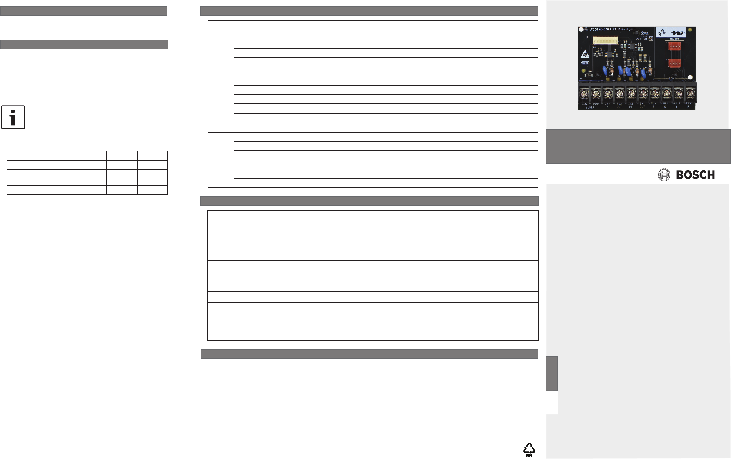
1 | Overview
4 | Wiring
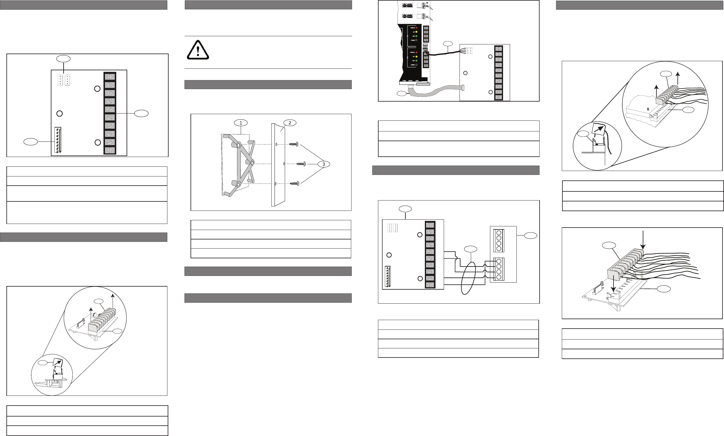
Perform the following steps to wire the B600 module.
Callout ― Description
1 ― ZONEX connection cable (P/N: F01U295103 - included)
2 ― SDI interconnect cable (P/N: F01U079745 - included,
also sold in a 10-pack - P/N: B501-10)
SDI2
COMPWR ZX2
IN
ZX2
OUT
ZX1
IN
ZX1
OUT
COM
B
SDI B
G
SDI A
Y
PWR
R
ZONEX
RESETZONEX TAMPER
SDI2
PWR+/R
A/Y
B/G
COM/B
PWR+/R
A/Y
B/G
COM/B
24
25
26
27
28
29
23
26
SDIx
ire
1
2
Figure 4.1: Wiring the module to the control panel (B9512G
shown)
Callout ― Description
1 ― B600 ZONEX terminal connector
2 ― SDI connection (requires SDIx bus to be congured to
work as SDI)
3 ― ZONEX and SDI bus terminal strip (removable terminal
strip from legacy G Series control panels plugs directly
into this connector).
Callout ― Description
1 ― Module and three hole mounting bracket
2 ― Control panel enclosure
3 ― Mounting screws (3)
4.1 | Wiring to the control panel
Use the module’s cables provided when you wire the module
to a control panel. Program the SDIx bus to operate as the SDI
bus. Make cable connections to the control panel as shown in
Figure 4.1.
Using your existing terminal wiring strip, retrotting your
current ZONEX devices to your new control panel is easy.
Remove the terminal strip which contains the legacy ZONEX
devices from the legacy control panel by tilting the strip up
and outward. Do not remove the wiring from the terminal strip.
Refer to Figure 5.1.
1
2
1
Figure 5 .1: Removing terminal strip from legacy control panel
1
2
Figure 5.2: Inserting the terminal strip into the B600
Callout ― Description
1 ― Terminal strip (from legacy control panel)
2 ― B600
1
2
1
Figure 2.1: Removing the terminal strip from the B600
Callout ― Description
1 ― B600 terminal strip (out of the box)
2 ― B600 module
Callout ― Description
1 ― Terminal strip (from legacy control panel)
2 ― Legacy control panel (for example; D9412GV2)
Insert the terminal strip with the legacy ZONEX devices onto
the B600 module. Refer to Figure 5.2.
Callout ― Description
1 ― B600
2 ― ZONEX 1 wiring
3 ― D8125
COMPWR ZX2
IN
ZX2
OUT
ZX1
IN
ZX1
OUT
COM
B
SDI B
G
SDI A
Y
PWR
R
ZONEX
D8125
POPEX
(+)
(+)
GND
OUT
IN
AUX
(-)
(-)
1
3
2
Figure 4.2: Wiring a B600 module to a legacy module (D8125
shown)
Use your existing Legacy ZONEX devices to connect to the
B600. Refer to the gure below for an example of wiring legacy
ZONEX devices.
4.2 | Wire to legacy ZONEX devices
3 | Installation
Mount the module into the lower right area of the control
panel enclosure’s 3-hole mounting pattern using the supplied
screws and mounting bracket. Refer to Figure 3.1.
Figure 3.1: Mounting the module in the enclosure
Install the module in the enclosure, and then connect it to
the control panel.
3.1 | Mount the module in the enclosure
CAUTION!
Remove all power (AC and battery) before making any
connections. Failure to do so might result in personal
injury and/or equipment damage.
2 | Pre-installation
Remove the terminal strip (provided) from the B600 prior
to retrot applications. Do this by tilting the strip up and
outward. Refer to Figure 2.1.
Refer to Section 4.4. for new installations which require
wiring into the B600 terminal strip.
5 | Retrot from legacy control panel
The B600 Retrot (ZONEX) module enables the use of ZONEX
devices on the B9512G/B8512G control panel. The B600
module connects to the control panel through a proprietary
connection (cable provided with module) and establishes
communication with ZONEX modules through the supporting
ZONEX terminals.
1
2
3
COMPWRZX2
IN
ZX2
OUT
ZX1
IN
ZX1
OUT
COM
B
SDI B
G
SDI A
Y
PWR
R
ZONEX
Figure 1.1: B600 module
Bosch Security Systems, Inc.
130 Perinton Parkway
Fairport, NY 14450
USA
www.boschsecurity.com
© 2015 Bosch Security Systems, Inc. F.01U.297.387 | 05 | 2015.03
Trademarks
All hardware and software product names used in this document are likely to be registered trademarks and must be treated
accordingly.
Bosch Security Systems, Inc. product manufacturing dates
Use the serial number located on the product label and refer to the Bosch Security Systems, Inc. website at
http://www.boschsecurity.com/datecodes/.
Copyright
This document is the intellectual property of Bosch Security Systems, Inc. and is protected by copyright. All rights reserved.
9 | Specications
Dimensions 2.76 in x 3.86 in x 1.03 in
(70.3 mm x 98.0 mm x 26.0 mm)
Voltage (input) 12 VDC nominal
Current Standby: 12 mA + total device current
Alarm: 12 mA + total device current
Operating temperature 0°C to +50°C (+32°F to +122°F)
Relative humidity 5% to 93% at +32°C (+90°F) non-condensing
Terminal wire size 12 AWG to 22 AWG (2 mm to 0.65 mm)
SDI wiring Use the supplied interconnect cable (P/N: F01U079745) (also sold in a 10-pack - P/N: B501-10)
ZONEX wiring Use the supplied ZONEX connection cable (P/N: F01U295103)
Compatible control
panels
B9512G/B9512G-E/B8512G/B8512G-E (Refer to the control panel installation document for the
number of supported devices.)
Compatible accessories D8125 Zone Expansion Module
D8128D OctoPOPIT Module
D8129 Octo-relay Module
8 | Certications
Region Certication
US UL 365 - Police Station Connected Burglar Alarm Units and Systems
UL 609 - Local Burglar Alarm Units and Systems
UL 636 - Holdup Alarm Units and Systems
UL 864 - Control Units and Accessories for Fire Alarm Systems
UL 985 - Household Fire Warning System Units
UL 1023 - Household Burglar-Alarm System Units
UL 1076 - Proprietary Burglar Alarm Units and Systems
UL 1610 - Central Station Burglar Alarm Units
ANSI/SIA CP-01:2010
FCC Part 15 Class B
CSFM - California Ofce of The State Fire Marshal
CA Canada CAN/ULC S303 - Local Burglar Alarm Units and Systems
CAN/ULC S304 - Signal Receiving Centre and Premise Alarm Control Units
CAN/ULC S545 - Residential Fire Warning Alarm Systems Control units
ULC-ORD C1023 - Household Burglar Alarm System Units
ULC-ORD C1076 - Proprietary Burglar Alarm Units and Systems
ICES-003 - Digital Apparatus
7 | B600 device compatibility list
The B600 ZONEX module includes two ZONEX busses (ZONEX1,
ZONEX2). Each ZONEX bus supports up to 15 D8128D modules,
and/or up to D8129 Octo-relay modules. D8128D and D8129
modules can be combined on a single ZONEX bus. Total number
of modules cannot exceed 15 modules. Refer to the following
table for supported compatibilities.
6 | Conguration
Use Remote Programming Software (RPS) to congure your
new POPEX devices and/or your ZONEX/POPEX devices
.
Compatible module ZONEX 1 ZONEX 2
D8125 Zone Expansion Module
1 1
D8128D
OctoPOPIT Eight-point
Expander
15 15
D8129 Octo-relay Module
15 15
Table 7.1: B600 device compatibility list
NOTICE!
The total number of both D8128D and D8129 modules
cannot exceed 15 on a single ZONEX bus. For
example, if you have 10 D8128D modules you can only
have 5 D8129 modules.
en Installation Guide
Retrot ZONEX Module
B600
