Bosch F01U323389 03_B6512_PEG Installation Manual (Program Entry Guide B6512) B6512 Peg En US 23243314699
User Manual: Bosch Installation Manual (Program Entry Guide B6512) B6512 IP control panel, 96 points
Open the PDF directly: View PDF ![]() .
.
Page Count: 256 [warning: Documents this large are best viewed by clicking the View PDF Link!]
- Table of contents
- 1 Remote Programming Software
- 2 Compliance Settings
- 3 Panel Wide Parameters
- 3.1 Phone and Phone Parameters
- 3.2 On Board Ethernet (IP) Communicator
- 3.2.1 IPv6 Mode
- 3.2.2 IPv4 DHCP/AutoIP Enable
- 3.2.3 IPv4 Address
- 3.2.4 IPv4 Subnet Mask
- 3.2.5 IPv4 Default Gateway
- 3.2.6 IPv4 DNS Server IP Address
- 3.2.7 IPv6 DNS Server IP Address
- 3.2.8 UPnP (Universal Plug and Play) Enable
- 3.2.9 ARP Cache Timeout (sec.)
- 3.2.10 Module Hostname
- 3.2.11 TCP / UDP Port Number
- 3.2.12 TCP Keep Alive Time (sec.)
- 3.2.13 IPv4 Test Address
- 3.2.14 IPv6 Test Address
- 3.2.15 Alternate IPv4 DNS server IP address
- 3.2.16 Alternate IPv6 DNS server IP address
- 3.3 Cellular Plug-in Module
- 3.3.1 Inbound SMS
- 3.3.2 Session Keep Alive Period (min.)
- 3.3.3 Inactivity Timeout (min.)
- 3.3.4 Reporting Delay for Low Signal Strength (sec.)
- 3.3.5 Reporting Delay for No Towers (sec.)
- 3.3.6 Outgoing SMS Length
- 3.3.7 Network Access Point Name (APN)
- 3.3.8 Network Access Point User Name
- 3.3.9 Network Access Point Password
- 3.3.10 SIM PIN
- 3.4 Cloud Remote Connect
- 3.5 IP cameras
- 3.6 Bosch Connected Cameras
- 3.7 Live (video)
- 3.8 Reporting Overview
- 3.9 Report Routing
- 3.10 Communicator, overview
- 3.11 Enhanced Communication
- 3.12 SDI2 RPS / Enhanced Communication
- 3.13 Power Supervision
- 3.14 RPS Parameters
- 3.15 Miscellaneous
- 3.15.1 Duress Type
- 3.15.2 Cancel Reports
- 3.15.3 Call for Service Text - First Language
- 3.15.4 Call for Service Text - Second Language
- 3.15.5 On Site Authorization for Firmware Update
- 3.15.6 Enclosure Tamper Enable
- 3.15.7 Fire Summary Sustain
- 3.15.8 Fire Supervision Event Type
- 3.15.9 Fire Trouble Resound
- 3.15.10 Early Ambush Time
- 3.15.11 Second Ambush Code
- 3.15.12 Abort Window
- 3.15.13 Passcode Length
- 3.15.14 Swinger Bypass Count
- 3.15.15 Remote Warning
- 3.15.16 Crystal Time Adjust
- 3.15.17 Part On Output
- 3.15.18 Early Area Armed Output
- 3.15.19 Daylight Saving Time
- 3.15.20 Date Format
- 3.15.21 Date Delimiter
- 3.15.22 Time Format
- 3.15.23 Time Zone
- 3.16 Personal Notification Destinations
- 3.17 Personal Notification Reports
- 3.18 Personal Notification Routing Attempts
- 3.19 Email Server Configuration
- 4 Area Wide Parameters
- 4.1 Area / Bell Parameters, Open / Close Options
- 4.1.1 Area Name Text
- 4.1.2 Area Name Text (Second Language)
- 4.1.3 Area On
- 4.1.4 Account Number
- 4.1.5 Force Arm/Bypass Max
- 4.1.6 Delay Restorals
- 4.1.7 Exit Tone
- 4.1.8 Exit Delay Time
- 4.1.9 Auto Watch
- 4.1.10 Restart Time
- 4.1.11 Duress Enable
- 4.1.12 Area Type
- 4.1.13 Two Man Rule?
- 4.1.14 Early Ambush?
- 4.1.15 Fire Time
- 4.1.16 Fire Pattern
- 4.1.17 Burg Time
- 4.1.18 Burg Pattern
- 4.1.19 Gas Pattern
- 4.1.20 Single Ring
- 4.1.21 Bell Test
- 4.1.22 Account O/C
- 4.1.23 Area O/C
- 4.1.24 Disable O/C in Window
- 4.1.25 Auto Close
- 4.1.26 Fail to Open
- 4.1.27 Fail to Close
- 4.1.28 Latest Close Time
- 4.1.29 Restricted O/C
- 4.1.30 Part On O/C
- 4.1.31 Exit Delay Restart
- 4.1.32 All On- No Exit
- 4.1.33 Exit Delay Warning
- 4.1.34 Entry Delay Warning
- 4.1.35 Area Re-Arm Time
- 4.2 Area Arming Text
- 4.1 Area / Bell Parameters, Open / Close Options
- 5 Keypads
- 5.1 Keypad Assignments
- 5.1.1 Keypad Name
- 5.1.2 Keypad Name (Second Language)
- 5.1.3 Keypad Type
- 5.1.4 Area Assignment
- 5.1.5 Keypad Language
- 5.1.6 Scope
- 5.1.7 Area in Scope
- 5.1.8 Passcode Follows Scope?
- 5.1.9 Enter Key Output
- 5.1.10 Passcode Enter Function
- 5.1.11 Dual Authentication
- 5.1.12 Dual Authentication Duration
- 5.1.13 Assign Door
- 5.1.14 Trouble Tone
- 5.1.15 Entry Tone
- 5.1.16 Exit Tone
- 5.1.17 Arm Area Warning Tone
- 5.1.18 Close Door Warning Tone
- 5.1.19 Idle Scroll Lock
- 5.1.20 Function Lock
- 5.1.21 Abort Display
- 5.1.22 Cancel Display
- 5.1.23 Nightlight Enable
- 5.1.24 Nightlight Brightness
- 5.1.25 Silence Keypress Tone
- 5.1.26 Show Date and Time
- 5.1.27 Keypad Volume
- 5.1.28 Keypad Brightness
- 5.1.29 Disable Presence Sensor
- 5.1.30 Disable Token Reader
- 5.1.31 Enable Tamper Switch
- 5.1.32 Feature Button Option
- 5.2 Global Keypad Settings
- 5.3 Global Wireless Keyfob
- 5.1 Keypad Assignments
- 6 Custom Functions
- 7 Shortcut Menu
- 8 Output Parameters
- 8.1 Area Wide Outputs
- 8.2 Panel Wide Outputs
- 8.2.1 AC Failure
- 8.2.2 Battery Trouble
- 8.2.3 Phone Fail
- 8.2.4 Comm Fail
- 8.2.5 Log % Full
- 8.2.6 Summary Fire
- 8.2.7 Summary Alarm
- 8.2.8 Summary Fire Trouble
- 8.2.9 Summary Supervisory Fire
- 8.2.10 Summary Trouble
- 8.2.11 Summary Supervisory Burg
- 8.2.12 Summary Gas Output
- 8.2.13 Summary Gas Supervisory Output
- 8.2.14 Summary Gas Trouble Output
- 8.3 Output Configuration
- 9 User Configuration
- 9.1 User Assignments (passcodes)
- 9.2 User Groups
- 9.3 User (keypad) Functions
- 9.3.1 All On, Delay
- 9.3.2 All On, Instant
- 9.3.3 Part On, Instant
- 9.3.4 Part On, Delay
- 9.3.5 Watch Mode
- 9.3.6 View Area Status
- 9.3.7 View/Delete Event Memory
- 9.3.8 View Point Status
- 9.3.9 Walk Test (all Non-Fire Burg Points)
- 9.3.10 Walk Test All Fire Points
- 9.3.11 Send Report (Test/Status)
- 9.3.12 Door Control
- 9.3.13 Set Keypad Brightness / Volume / Keypress
- 9.3.14 Set/Show Date and Time
- 9.3.15 Change Passcodes
- 9.3.16 Add/Edit User
- 9.3.17 Delete User
- 9.3.18 Extend Close
- 9.3.19 View Event Log
- 9.3.20 User Command 7
- 9.3.21 User Command 9
- 9.3.22 Bypass a Point
- 9.3.23 Unbypass a Point
- 9.3.24 Reset Sensor
- 9.3.25 Change Output
- 9.3.26 Remote Program
- 9.3.27 Go to area
- 9.3.28 Display Panel Type and Revision
- 9.3.29 Service Walk All Points
- 9.3.30 Change Skeds
- 9.3.31 Walk Test All Invisible Burg Points
- 9.3.32 Silence Function
- 9.3.33 Custom Function
- 9.3.34 Keypad Programming
- 9.4 Authority Levels
- 9.4.1 Authority Level Name
- 9.4.2 Authority Level Name (Second Language)
- 9.4.3 Disarm Select
- 9.4.4 All On, Delay
- 9.4.5 All On, Instant
- 9.4.6 Part On, Instant
- 9.4.7 Part On, Delay
- 9.4.8 Watch Mode
- 9.4.9 View Area Status
- 9.4.10 View Event Memory
- 9.4.11 View Point Status
- 9.4.12 Walk Test (All Non-Fire Burg Points)
- 9.4.13 Walk Test All Fire Points
- 9.4.14 Walk Test All Invisible Burg Points
- 9.4.15 Service Walk All Points
- 9.4.16 Send Report (Test / Status)
- 9.4.17 Cycle Door
- 9.4.18 (Un)Lock door
- 9.4.19 Secure Door
- 9.4.20 Change Keypad Display
- 9.4.21 Change Date and Time
- 9.4.22 Change Passcodes
- 9.4.23 Add User Passcodes / Card / Level
- 9.4.24 Delete User Passcode / Card/ Level
- 9.4.25 Extend Close
- 9.4.26 View Event Log
- 9.4.27 User Command 7
- 9.4.28 User Command 9
- 9.4.29 Bypass a Point
- 9.4.30 Unbypass a Point
- 9.4.31 Reset Sensor(s)
- 9.4.32 Change Output(s)
- 9.4.33 Remote Program
- 9.4.34 Go to Area
- 9.4.35 Display Panel Type and Revision
- 9.4.36 Change Skeds
- 9.4.37 Custom Function
- 9.4.38 Force Arm
- 9.4.39 Send Area Open/Close
- 9.4.40 Restricted Open/Close
- 9.4.41 Part On Open/Close
- 9.4.42 Send Duress
- 9.4.43 Arm by Passcode
- 9.4.44 Disarm by Passcode
- 9.4.45 Security Level
- 9.4.46 Disarm Level
- 9.4.47 Function Level
- 9.4.48 Keyfob Arm
- 9.4.49 Keyfob Disarm
- 9.4.50 Firmware Update
- 9.4.51 Silence Function
- 10 Points
- 10.1 Point Assignments
- 10.2 Cross Point Parameters
- 10.3 Point Profiles
- 10.3.1 Point Profile Text (First Language)
- 10.3.2 Point Profile Text (Second Language)
- 10.3.3 Point Response overview
- 10.3.4 Point Type
- 10.3.5 Point Response
- 10.3.6 Entry Delay
- 10.3.7 Entry Tone Off
- 10.3.8 Silent Bell
- 10.3.9 Ring Until Restored
- 10.3.10 Audible After Two Fails
- 10.3.11 Invisible Point
- 10.3.12 Buzz on Fault
- 10.3.13 Watch Point
- 10.3.14 Output Response Type
- 10.3.15 Display as Device
- 10.3.16 Local While Disarmed
- 10.3.17 Local While Armed
- 10.3.18 Disable Restorals
- 10.3.19 Force Arm Returnable
- 10.3.20 Bypass Returnable
- 10.3.21 Bypassable
- 10.3.22 Swinger Bypass
- 10.3.23 Report Bypass at Occurrence
- 10.3.24 Defer Bypass Report
- 10.3.25 Cross Point
- 10.3.26 Alarm Verify
- 10.3.27 Resettable
- 10.3.28 Alarm Abort
- 10.3.29 Wireless Point Supervision Time
- 10.3.30 Custom Function
- 10.3.31 Monitor Delay
- 10.3.32 Delay Response, Disarmed
- 10.3.33 Delay Response, Armed
- 10.3.34 Circuit Style
- 10.3.35 Normal State
- 10.4 Point Profile descriptions
- 11 Schedules
- 11.1 Open/Close Windows
- 11.2 User group windows
- 11.3 Skeds
- 11.4 Holiday indexes
- 11.5 Sked Function descriptions
- 11.5.1 All On Delay
- 11.5.2 All On Instant
- 11.5.3 Part On Delay
- 11.5.4 Part On Instant
- 11.5.5 Disarm
- 11.5.6 Extend Close
- 11.5.7 Bypass a Point
- 11.5.8 Unbypass a Point
- 11.5.9 Unbypass All Points
- 11.5.10 Reset Sensors
- 11.5.11 Turn Output On
- 11.5.12 Turn Output Off
- 11.5.13 Toggle Output
- 11.5.14 One-Shot Output
- 11.5.15 Reset All Outputs
- 11.5.16 Delay
- 11.5.17 Answer RPS
- 11.5.18 Contact RPS
- 11.5.19 Contact RPS User Port
- 11.5.20 Send Status Report
- 11.5.21 Send Test Report
- 11.5.22 Send Test on Off Normal
- 11.5.23 Go to Area
- 11.5.24 Watch On
- 11.5.25 Watch Off
- 11.5.26 Show Date & Time
- 11.5.27 Sound Watch Tone
- 11.5.28 Set Keypad Volume
- 11.5.29 Set Keypad Brightness
- 11.5.30 Trouble Silence
- 11.5.31 Alarm Silence
- 11.5.32 Execute Custom Function
- 12 Access
- 12.1 Door #
- 12.1.1 Door Name Text
- 12.1.2 Door Name Text (second language)
- 12.1.3 Door Source
- 12.1.4 Entry Area
- 12.1.5 Associated Keypad #
- 12.1.6 Custom Function
- 12.1.7 Door Point
- 12.1.8 Door Point Debounce
- 12.1.9 Interlock Point
- 12.1.10 Auto Door
- 12.1.11 Fire Unlock
- 12.1.12 Disarm on Open
- 12.1.13 Strike Time
- 12.1.14 Shunt Time
- 12.1.15 Buzz Time
- 12.1.16 Extend Time
- 12.1.17 Deactivate on Open
- 12.1.18 RTE Shunt Only
- 12.1.19 RTE Input Debounce
- 12.1.20 REX Shunt Only
- 12.1.21 REX Input Debounce
- 12.1.22 Access Granted
- 12.1.23 No Entry
- 12.1.24 Enter Request
- 12.1.25 Exit Request
- 12.1.26 Failure Mode
- 12.1.27 Enclosure Tamper
- 12.2 Global Access settings
- 12.1 Door #
- 13 Automation / Remote App
- 14 SDI2 modules
- 14.1 B208 Octo-input
- 14.2 B308 Octo-output
- 14.3 (B42x) IP Communicator
- 14.3.1 Module Enclosure Tamper
- 14.3.2 IPv6 Mode
- 14.3.3 IPv4 DHCP/AutoIP Enable
- 14.3.4 IPv4 Address
- 14.3.5 IPv4 Subnet Mask
- 14.3.6 IPv4 Default Gateway
- 14.3.7 IPv4 DNS Server IP Address
- 14.3.8 IPv6 DNS Server IP Address
- 14.3.9 UPnP (Universal Plug and Play) Enable
- 14.3.10 HTTP Port Number
- 14.3.11 ARP Cache Timeout (sec.)
- 14.3.12 Web/USB Access Enable
- 14.3.13 Web/USB Access Password
- 14.3.14 Firmware Upgrade Enable
- 14.3.15 Module Hostname
- 14.3.16 Unit Description
- 14.3.17 TCP/UDP Port Number
- 14.3.18 TCP Keep Alive Time
- 14.3.19 IPv4 Test Address
- 14.3.20 IPv6 Test Address
- 14.3.21 Web and Automation Security
- 14.3.22 Alternate IPv4 DNS server IP address
- 14.3.23 Alternate IPv6 DNS server IP address
- 14.4 B450 cellular
- 14.4.1 Inbound SMS
- 14.4.2 Session Keep Alive Period (min.)
- 14.4.3 Inactivity Time Out (min.)
- 14.4.4 Reporting Delay for Low Signal Strength (sec.)
- 14.4.5 Reporting Delay for Single Tower (sec.)
- 14.4.6 Reporting Delay for No Towers (sec.)
- 14.4.7 Outgoing SMS Length
- 14.4.8 SIM PIN
- 14.4.9 Network Access Point Name (APN)
- 14.4.10 Network Access Point User Name
- 14.4.11 Network Access Point Password
- 14.5 B520 aux power supply
- 14.6 Wireless Receiver
- 14.7 Wireless Repeater
- 15 Hardware switch settings
- 15.1 Keypad address
- 15.2 B208 Octo-input Module switch settings
- 15.3 B308 Octo-output Module switch settings
- 15.4 B426 Ethernet Communication Module switch settings
- 15.5 B450 Cellular Module switch settings
- 15.6 B520 Power Supply switch settings
- 15.7 B810 RADION wireless receiver switch settings
- 15.8 B820 Inovonics wireless receiver switch settings
- 15.9 B901 Access Module switch settings
- 16 Configuring for Cellular Service
- 17 IP Address and Domain Name formats

Control Panel
B6512
en Program Entry Guide

Control Panel Table of contents | en 3
Bosch Security Systems, Inc. Program Entry Guide 2017.03 | 03 | F.01U.323.389
Table of contents
1Remote Programming Software 16
2Compliance Settings 17
2.1 SIA CP-01 Verification 17
2.2 ULC Compliance 18
2.2.1 CAN/ULC-S304 compliance 18
2.2.2 CAN/ULC-S559, Required Programming 18
2.2.3 CAN/ULC-S559, Recommended Programming 23
2.3 Supervision configuration 27
3Panel Wide Parameters 29
3.1 Phone and Phone Parameters 29
3.1.1 Phone Destination 1 (to 4) 29
3.1.2 Phone Destination 1 (to 4) Format 29
3.1.3 DTMF Dialing 29
3.1.4 Phone Supervision Time 30
3.1.5 Alarm on Fail 30
3.1.6 Buzz on Fail 30
3.1.7 Expand Test Report 31
3.1.8 PSTN Compatibility 31
3.2 On Board Ethernet (IP) Communicator 31
3.2.1 IPv6 Mode 31
3.2.2 IPv4 DHCP/AutoIP Enable 32
3.2.3 IPv4 Address 32
3.2.4 IPv4 Subnet Mask 32
3.2.5 IPv4 Default Gateway 33
3.2.6 IPv4 DNS Server IP Address 33
3.2.7 IPv6 DNS Server IP Address 33
3.2.8 UPnP (Universal Plug and Play) Enable 34
3.2.9 ARP Cache Timeout (sec.) 34
3.2.10 Module Hostname 34
3.2.11 TCP / UDP Port Number 34
3.2.12 TCP Keep Alive Time (sec.) 35
3.2.13 IPv4 Test Address 35
3.2.14 IPv6 Test Address 35
3.2.15 Alternate IPv4 DNS server IP address 35
3.2.16 Alternate IPv6 DNS server IP address 36
3.3 Cellular Plug-in Module 36
3.3.1 Inbound SMS 36
3.3.2 Session Keep Alive Period (min.) 36
3.3.3 Inactivity Timeout (min.) 37
3.3.4 Reporting Delay for Low Signal Strength (sec.) 37
3.3.5 Reporting Delay for No Towers (sec.) 38
3.3.6 Outgoing SMS Length 38
3.3.7 Network Access Point Name (APN) 39
3.3.8 Network Access Point User Name 39
3.3.9 Network Access Point Password 39
3.3.10 SIM PIN 39
3.4 Cloud Remote Connect 40
3.4.1 Cloud Remote Connect (Ethernet) 40

4en | Table of contents Control Panel
2017.03 | 03 | F.01U.323.389 Program Entry Guide Bosch Security Systems, Inc.
3.4.2 Cloud Remote Connect (Cellular) 40
3.5 IP cameras 40
3.5.1 Camera name 41
3.5.2 Camera name (second language) 41
3.5.3 URL or IP address 41
3.6 Bosch Connected Cameras 41
3.6.1 RCP+ port # 42
3.6.2 Service password 42
3.6.3 Supervision period (sec.) 42
3.7 Live (video) 42
3.7.1 Port # 42
3.7.2 Use HTTPS? 43
3.7.3 User Name 43
3.7.4 Password 43
3.8 Reporting Overview 44
3.9 Report Routing 46
3.9.1 Fire Reports 51
3.9.2 Gas Reports 52
3.9.3 Burglar Reports 52
3.9.4 Personal Emergency Reports 53
3.9.5 User Reports 53
3.9.6 Test Reports 54
3.9.7 Diagnostic Reports 54
3.9.8 Output Reports 55
3.9.9 Auto Function Reports 56
3.9.10 RPS Reports 56
3.9.11 Point Reports 57
3.9.12 User Change Reports 57
3.9.13 Access Reports 58
3.10 Communicator, overview 58
3.10.1 Primary Destination Device 59
3.10.2 Backup Destination Device 60
3.10.3 RG Same Network Receiver 61
3.10.4 Time Synchronization 61
3.11 Enhanced Communication 62
3.11.1 Reporting Format 62
3.11.2 Network Address 62
3.11.3 Port Number 63
3.11.4 Receiver Supervision Time 63
3.11.5 Poll Rate (sec.) 64
3.11.6 ACK Wait Time (sec.) 66
3.11.7 Retry Count 66
3.11.8 AES Key Size 67
3.11.9 AES Encryption Key 67
3.12 SDI2 RPS / Enhanced Communication 67
3.12.1 Enable Enhanced Communication? 67
3.12.2 Answer RPS Over Network? 68
3.12.3 RPS Address Verification 68
3.12.4 RPS Network Address 68

Control Panel Table of contents | en 5
Bosch Security Systems, Inc. Program Entry Guide 2017.03 | 03 | F.01U.323.389
3.12.5 RPS Port Number 68
3.13 Power Supervision 69
3.13.1 AC Fail Time 69
3.13.2 Resend AC Fail 69
3.13.3 AC Fail Display 69
3.13.4 AC Fail / Restoral Report 69
3.13.5 AC Tag Along 69
3.13.6 AC / Battery Buzz 70
3.13.7 Battery Fail / Restoral Report 70
3.14 RPS Parameters 70
3.14.1 RPS Passcode 70
3.14.2 Log % Full 70
3.14.3 Contact RPS if Log % Full 71
3.14.4 RPS Call Back 71
3.14.5 RPS Line Monitor 71
3.14.6 Answer Armed 72
3.14.7 Answer Disarmed 72
3.14.8 RPS Phone # 73
3.14.9 RPS Modem Speed 73
3.15 Miscellaneous 73
3.15.1 Duress Type 73
3.15.2 Cancel Reports 74
3.15.3 Call for Service Text - First Language 74
3.15.4 Call for Service Text - Second Language 75
3.15.5 On Site Authorization for Firmware Update 75
3.15.6 Enclosure Tamper Enable 76
3.15.7 Fire Summary Sustain 76
3.15.8 Fire Supervision Event Type 76
3.15.9 Fire Trouble Resound 77
3.15.10 Early Ambush Time 77
3.15.11 Second Ambush Code 77
3.15.12 Abort Window 77
3.15.13 Passcode Length 78
3.15.14 Swinger Bypass Count 79
3.15.15 Remote Warning 80
3.15.16 Crystal Time Adjust 80
3.15.17 Part On Output 80
3.15.18 Early Area Armed Output 81
3.15.19 Daylight Saving Time 81
3.15.20 Date Format 81
3.15.21 Date Delimiter 81
3.15.22 Time Format 82
3.15.23 Time Zone 82
3.16 Personal Notification Destinations 84
3.16.1 Description 84
3.16.2 SMS Phone # / email address 84
3.16.3 User Language 84
3.16.4 Method 85
3.17 Personal Notification Reports 85

6en | Table of contents Control Panel
2017.03 | 03 | F.01U.323.389 Program Entry Guide Bosch Security Systems, Inc.
3.18 Personal Notification Routing Attempts 86
3.19 Email Server Configuration 86
3.19.1 Email server name/address 87
3.19.2 Email server port number 88
3.19.3 Email server authentication/encryption 88
3.19.4 Authentication user name 88
3.19.5 Authentication password 88
4Area Wide Parameters 89
4.1 Area / Bell Parameters, Open / Close Options 89
4.1.1 Area Name Text 89
4.1.2 Area Name Text (Second Language) 89
4.1.3 Area On 90
4.1.4 Account Number 90
4.1.5 Force Arm/Bypass Max 91
4.1.6 Delay Restorals 91
4.1.7 Exit Tone 91
4.1.8 Exit Delay Time 91
4.1.9 Auto Watch 92
4.1.10 Restart Time 92
4.1.11 Duress Enable 93
4.1.12 Area Type 94
4.1.13 Two Man Rule? 96
4.1.14 Early Ambush? 97
4.1.15 Fire Time 97
4.1.16 Fire Pattern 98
4.1.17 Burg Time 98
4.1.18 Burg Pattern 98
4.1.19 Gas Pattern 99
4.1.20 Single Ring 99
4.1.21 Bell Test 100
4.1.22 Account O/C 100
4.1.23 Area O/C 101
4.1.24 Disable O/C in Window 101
4.1.25 Auto Close 101
4.1.26 Fail to Open 102
4.1.27 Fail to Close 102
4.1.28 Latest Close Time 102
4.1.29 Restricted O/C 103
4.1.30 Part On O/C 103
4.1.31 Exit Delay Restart 104
4.1.32 All On- No Exit 104
4.1.33 Exit Delay Warning 104
4.1.34 Entry Delay Warning 105
4.1.35 Area Re-Arm Time 105
4.2 Area Arming Text 106
4.2.1 Area name text 106
4.2.2 Account is On text 106
4.2.3 Area # is On text 106
4.2.4 Area # is not Ready text 107

Control Panel Table of contents | en 7
Bosch Security Systems, Inc. Program Entry Guide 2017.03 | 03 | F.01U.323.389
4.2.5 Area # is Off text 107
5Keypads 108
5.1 Keypad Assignments 108
5.1.1 Keypad Name 108
5.1.2 Keypad Name (Second Language) 108
5.1.3 Keypad Type 108
5.1.4 Area Assignment 109
5.1.5 Keypad Language 109
5.1.6 Scope 109
5.1.7 Area in Scope 110
5.1.8 Passcode Follows Scope? 110
5.1.9 Enter Key Output 110
5.1.10 Passcode Enter Function 111
5.1.11 Dual Authentication 112
5.1.12 Dual Authentication Duration 112
5.1.13 Assign Door 112
5.1.14 Trouble Tone 113
5.1.15 Entry Tone 113
5.1.16 Exit Tone 113
5.1.17 Arm Area Warning Tone 114
5.1.18 Close Door Warning Tone 114
5.1.19 Idle Scroll Lock 114
5.1.20 Function Lock 114
5.1.21 Abort Display 115
5.1.22 Cancel Display 115
5.1.23 Nightlight Enable 115
5.1.24 Nightlight Brightness 115
5.1.25 Silence Keypress Tone 116
5.1.26 Show Date and Time 116
5.1.27 Keypad Volume 116
5.1.28 Keypad Brightness 116
5.1.29 Disable Presence Sensor 117
5.1.30 Disable Token Reader 117
5.1.31 Enable Tamper Switch 117
5.1.32 Feature Button Option 117
5.2 Global Keypad Settings 118
5.2.1 A key Response 118
5.2.2 A Key Custom Function 118
5.2.3 B Key Response 119
5.2.4 B Key Custom Function 119
5.2.5 C Key Response 119
5.2.6 C Key Custom Function 120
5.2.7 Manual Silent Alarm Audible on Comm Trouble 120
5.2.8 Comm Trouble Options 121
5.3 Global Wireless Keyfob 121
5.3.1 Keyfob Function A Custom Function 121
5.3.2 Keyfob Function B Custom Function 121
5.3.3 Keyfob Panic Options 122
6Custom Functions 123

8en | Table of contents Control Panel
2017.03 | 03 | F.01U.323.389 Program Entry Guide Bosch Security Systems, Inc.
6.1 Custom Function Text 123
6.2 Custom Function Text (Second Language) 123
6.3 Functions 123
7Shortcut Menu 126
7.1 Function 126
7.2 Set/Clear all 126
7.3 Address # 127
8Output Parameters 128
8.1 Area Wide Outputs 129
8.1.1 Alarm Bell 129
8.1.2 Fire Bell 129
8.1.3 Reset Sensors 130
8.1.4 Fail to Close/Part On Armed 130
8.1.5 Force Armed 130
8.1.6 Watch Mode 131
8.1.7 Area Armed 131
8.1.8 Area Off 131
8.1.9 Area Fault 132
8.1.10 Duress Output 132
8.1.11 Part On Fault 132
8.1.12 Silent Alarm 132
8.1.13 Gas Bell 133
8.2 Panel Wide Outputs 133
8.2.1 AC Failure 133
8.2.2 Battery Trouble 133
8.2.3 Phone Fail 133
8.2.4 Comm Fail 134
8.2.5 Log % Full 134
8.2.6 Summary Fire 134
8.2.7 Summary Alarm 135
8.2.8 Summary Fire Trouble 135
8.2.9 Summary Supervisory Fire 135
8.2.10 Summary Trouble 136
8.2.11 Summary Supervisory Burg 136
8.2.12 Summary Gas Output 136
8.2.13 Summary Gas Supervisory Output 137
8.2.14 Summary Gas Trouble Output 137
8.3 Output Configuration 138
8.3.1 Output Source 138
8.3.2 Output Text 138
8.3.3 Output Text (Second Language) 138
8.3.4 Hide From User 139
9User Configuration 140
9.1 User Assignments (passcodes) 140
9.1.1 User Name 140
9.1.2 Passcode 140
9.1.3 Remote Access 140
9.1.4 User Group 141
9.1.5 Area Authorities 141

Control Panel Table of contents | en 9
Bosch Security Systems, Inc. Program Entry Guide 2017.03 | 03 | F.01U.323.389
9.1.6 Site Code 142
9.1.7 Card Data 142
9.1.8 Inovonics Keyfob RFID (B820) 142
9.1.9 RADION Keyfob RFID (B810) 143
9.1.10 Supervised 143
9.1.11 User language 143
9.2 User Groups 144
9.2.1 User Group Name 144
9.3 User (keypad) Functions 144
9.3.1 All On, Delay 144
9.3.2 All On, Instant 144
9.3.3 Part On, Instant 144
9.3.4 Part On, Delay 145
9.3.5 Watch Mode 145
9.3.6 View Area Status 145
9.3.7 View/Delete Event Memory 146
9.3.8 View Point Status 146
9.3.9 Walk Test (all Non-Fire Burg Points) 146
9.3.10 Walk Test All Fire Points 146
9.3.11 Send Report (Test/Status) 147
9.3.12 Door Control 147
9.3.13 Set Keypad Brightness / Volume / Keypress 147
9.3.14 Set/Show Date and Time 147
9.3.15 Change Passcodes 148
9.3.16 Add/Edit User 148
9.3.17 Delete User 148
9.3.18 Extend Close 148
9.3.19 View Event Log 149
9.3.20 User Command 7 149
9.3.21 User Command 9 149
9.3.22 Bypass a Point 149
9.3.23 Unbypass a Point 149
9.3.24 Reset Sensor 150
9.3.25 Change Output 150
9.3.26 Remote Program 150
9.3.27 Go to area 150
9.3.28 Display Panel Type and Revision 151
9.3.29 Service Walk All Points 151
9.3.30 Change Skeds 151
9.3.31 Walk Test All Invisible Burg Points 151
9.3.32 Silence Function 152
9.3.33 Custom Function 152
9.3.34 Keypad Programming 152
9.4 Authority Levels 153
9.4.1 Authority Level Name 153
9.4.2 Authority Level Name (Second Language) 153
9.4.3 Disarm Select 153
9.4.4 All On, Delay 154
9.4.5 All On, Instant 154

10 en | Table of contents Control Panel
2017.03 | 03 | F.01U.323.389 Program Entry Guide Bosch Security Systems, Inc.
9.4.6 Part On, Instant 154
9.4.7 Part On, Delay 155
9.4.8 Watch Mode 155
9.4.9 View Area Status 155
9.4.10 View Event Memory 156
9.4.11 View Point Status 156
9.4.12 Walk Test (All Non-Fire Burg Points) 156
9.4.13 Walk Test All Fire Points 156
9.4.14 Walk Test All Invisible Burg Points 157
9.4.15 Service Walk All Points 157
9.4.16 Send Report (Test / Status) 158
9.4.17 Cycle Door 158
9.4.18 (Un)Lock door 158
9.4.19 Secure Door 159
9.4.20 Change Keypad Display 159
9.4.21 Change Date and Time 159
9.4.22 Change Passcodes 160
9.4.23 Add User Passcodes / Card / Level 160
9.4.24 Delete User Passcode / Card/ Level 160
9.4.25 Extend Close 160
9.4.26 View Event Log 161
9.4.27 User Command 7 161
9.4.28 User Command 9 161
9.4.29 Bypass a Point 162
9.4.30 Unbypass a Point 162
9.4.31 Reset Sensor(s) 162
9.4.32 Change Output(s) 162
9.4.33 Remote Program 163
9.4.34 Go to Area 163
9.4.35 Display Panel Type and Revision 163
9.4.36 Change Skeds 164
9.4.37 Custom Function 164
9.4.38 Force Arm 164
9.4.39 Send Area Open/Close 165
9.4.40 Restricted Open/Close 165
9.4.41 Part On Open/Close 165
9.4.42 Send Duress 165
9.4.43 Arm by Passcode 166
9.4.44 Disarm by Passcode 166
9.4.45 Security Level 167
9.4.46 Disarm Level 167
9.4.47 Function Level 168
9.4.48 Keyfob Arm 169
9.4.49 Keyfob Disarm 169
9.4.50 Firmware Update 169
9.4.51 Silence Function 170
10 Points 171
10.1 Point Assignments 171
10.1.1 Source 171

Control Panel Table of contents | en 11
Bosch Security Systems, Inc. Program Entry Guide 2017.03 | 03 | F.01U.323.389
10.1.2 Text 171
10.1.3 2nd Language Text 172
10.1.4 Profile (Index) 172
10.1.5 Profile (Index) Description 172
10.1.6 Area 173
10.1.7 Debounce 173
10.1.8 Output 173
10.1.9 RADION RFID (B810) 174
10.1.10 RADION Device Type 174
10.1.11 Inovonics RFID (B820) 176
10.2 Cross Point Parameters 176
10.2.1 Cross Point Timer 176
10.3 Point Profiles 176
10.3.1 Point Profile Text (First Language) 177
10.3.2 Point Profile Text (Second Language) 177
10.3.3 Point Response overview 178
10.3.4 Point Type 178
10.3.5 Point Response 179
10.3.6 Entry Delay 185
10.3.7 Entry Tone Off 185
10.3.8 Silent Bell 186
10.3.9 Ring Until Restored 186
10.3.10 Audible After Two Fails 186
10.3.11 Invisible Point 187
10.3.12 Buzz on Fault 187
10.3.13 Watch Point 188
10.3.14 Output Response Type 188
10.3.15 Display as Device 189
10.3.16 Local While Disarmed 189
10.3.17 Local While Armed 189
10.3.18 Disable Restorals 190
10.3.19 Force Arm Returnable 190
10.3.20 Bypass Returnable 190
10.3.21 Bypassable 191
10.3.22 Swinger Bypass 191
10.3.23 Report Bypass at Occurrence 191
10.3.24 Defer Bypass Report 192
10.3.25 Cross Point 192
10.3.26 Alarm Verify 193
10.3.27 Resettable 193
10.3.28 Alarm Abort 194
10.3.29 Wireless Point Supervision Time 194
10.3.30 Custom Function 195
10.3.31 Monitor Delay 195
10.3.32 Delay Response, Disarmed 195
10.3.33 Delay Response, Armed 196
10.3.34 Circuit Style 196
10.3.35 Normal State 197
10.4 Point Profile descriptions 197

12 en | Table of contents Control Panel
2017.03 | 03 | F.01U.323.389 Program Entry Guide Bosch Security Systems, Inc.
10.4.1 24-Hour 197
10.4.2 Part On 197
10.4.3 Interior 198
10.4.4 Interior Follower 199
10.4.5 Keyswitch Maintained 199
10.4.6 Keyswith Momentary 199
10.4.7 Open / Close Point 200
10.4.8 Fire Point 200
10.4.9 Aux AC Supervision 200
10.4.10 Gas Point 200
10.4.11 Custom Function 200
11 Schedules 201
11.1 Open/Close Windows 201
11.1.1 Opening window timeline 201
11.1.2 Opening_Closing windows table 202
11.1.3 Sunday through Saturday 203
11.1.4 Open Early Begin 203
11.1.5 Open Window Start 204
11.1.6 Open Window Stop 205
11.1.7 Close Early Begin 205
11.1.8 Close Window Start 206
11.1.9 Close Window Stop 206
11.1.10 Xept on Holiday 207
11.1.11 Holiday # 207
11.1.12 Area # 208
11.2 User group windows 208
11.2.1 User Group 208
11.2.2 Sunday through Saturday 208
11.2.3 Group Enable Time 209
11.2.4 Group Disable Time 209
11.2.5 Xept Holiday 209
11.2.6 Holiday # 209
11.3 Skeds 210
11.3.1 Sked Name Text 210
11.3.2 Sked Name Text (Second Language) 210
11.3.3 Time Edit 210
11.3.4 Function 211
11.3.5 Time 212
11.3.6 Date 212
11.3.7 Sunday through Saturday 212
11.3.8 Xept on Holiday 213
11.3.9 Holiday # 213
11.4 Holiday indexes 213
11.4.1 Schedule 213
11.5 Sked Function descriptions 213
11.5.1 All On Delay 213
11.5.2 All On Instant 214
11.5.3 Part On Delay 214
11.5.4 Part On Instant 214

Control Panel Table of contents | en 13
Bosch Security Systems, Inc. Program Entry Guide 2017.03 | 03 | F.01U.323.389
11.5.5 Disarm 214
11.5.6 Extend Close 214
11.5.7 Bypass a Point 214
11.5.8 Unbypass a Point 214
11.5.9 Unbypass All Points 214
11.5.10 Reset Sensors 214
11.5.11 Turn Output On 214
11.5.12 Turn Output Off 215
11.5.13 Toggle Output 215
11.5.14 One-Shot Output 215
11.5.15 Reset All Outputs 215
11.5.16 Delay 215
11.5.17 Answer RPS 215
11.5.18 Contact RPS 215
11.5.19 Contact RPS User Port 216
11.5.20 Send Status Report 216
11.5.21 Send Test Report 216
11.5.22 Send Test on Off Normal 217
11.5.23 Go to Area 217
11.5.24 Watch On 217
11.5.25 Watch Off 217
11.5.26 Show Date & Time 217
11.5.27 Sound Watch Tone 217
11.5.28 Set Keypad Volume 218
11.5.29 Set Keypad Brightness 218
11.5.30 Trouble Silence 218
11.5.31 Alarm Silence 218
11.5.32 Execute Custom Function 218
12 Access 219
12.1 Door # 219
12.1.1 Door Name Text 219
12.1.2 Door Name Text (second language) 219
12.1.3 Door Source 219
12.1.4 Entry Area 219
12.1.5 Associated Keypad # 219
12.1.6 Custom Function 220
12.1.7 Door Point 220
12.1.8 Door Point Debounce 221
12.1.9 Interlock Point 221
12.1.10 Auto Door 222
12.1.11 Fire Unlock 222
12.1.12 Disarm on Open 222
12.1.13 Strike Time 223
12.1.14 Shunt Time 223
12.1.15 Buzz Time 223
12.1.16 Extend Time 223
12.1.17 Deactivate on Open 224
12.1.18 RTE Shunt Only 224
12.1.19 RTE Input Debounce 224

14 en | Table of contents Control Panel
2017.03 | 03 | F.01U.323.389 Program Entry Guide Bosch Security Systems, Inc.
12.1.20 REX Shunt Only 225
12.1.21 REX Input Debounce 225
12.1.22 Access Granted 226
12.1.23 No Entry 226
12.1.24 Enter Request 226
12.1.25 Exit Request 226
12.1.26 Failure Mode 226
12.1.27 Enclosure Tamper 227
12.2 Global Access settings 227
12.2.1 Card Type 227
13 Automation / Remote App 228
13.1 Automation Device 228
13.2 Status Rate 228
13.3 Automation Passcode 228
13.4 Mode 1 Automation Ethernet Port Number 229
13.5 Remote App 229
13.6 Remote App Passcode 229
14 SDI2 modules 230
14.1 B208 Octo-input 230
14.1.1 Enclosure Tamper 230
14.2 B308 Octo-output 230
14.2.1 Module Enclosure Tamper 231
14.3 (B42x) IP Communicator 231
14.3.1 Module Enclosure Tamper 231
14.3.2 IPv6 Mode 232
14.3.3 IPv4 DHCP/AutoIP Enable 232
14.3.4 IPv4 Address 232
14.3.5 IPv4 Subnet Mask 233
14.3.6 IPv4 Default Gateway 233
14.3.7 IPv4 DNS Server IP Address 233
14.3.8 IPv6 DNS Server IP Address 234
14.3.9 UPnP (Universal Plug and Play) Enable 234
14.3.10 HTTP Port Number 234
14.3.11 ARP Cache Timeout (sec.) 234
14.3.12 Web/USB Access Enable 235
14.3.13 Web/USB Access Password 235
14.3.14 Firmware Upgrade Enable 235
14.3.15 Module Hostname 235
14.3.16 Unit Description 236
14.3.17 TCP/UDP Port Number 236
14.3.18 TCP Keep Alive Time 236
14.3.19 IPv4 Test Address 236
14.3.20 IPv6 Test Address 237
14.3.21 Web and Automation Security 237
14.3.22 Alternate IPv4 DNS server IP address 237
14.3.23 Alternate IPv6 DNS server IP address 237
14.4 B450 cellular 238
14.4.1 Inbound SMS 238
14.4.2 Session Keep Alive Period (min.) 238

Control Panel Table of contents | en 15
Bosch Security Systems, Inc. Program Entry Guide 2017.03 | 03 | F.01U.323.389
14.4.3 Inactivity Time Out (min.) 238
14.4.4 Reporting Delay for Low Signal Strength (sec.) 239
14.4.5 Reporting Delay for Single Tower (sec.) 239
14.4.6 Reporting Delay for No Towers (sec.) 240
14.4.7 Outgoing SMS Length 240
14.4.8 SIM PIN 241
14.4.9 Network Access Point Name (APN) 241
14.4.10 Network Access Point User Name 242
14.4.11 Network Access Point Password 242
14.5 B520 aux power supply 242
14.5.1 Module Enable 243
14.5.2 Module Enclosure Tamper 243
14.5.3 One or Two Batteries 243
14.6 Wireless Receiver 243
14.6.1 Wireless Module Type 244
14.6.2 Module Enclosure Tamper 244
14.6.3 System (Repeater) Supervision Time 245
14.6.4 Low Battery Resound 245
14.6.5 Enable Jamming Detection 245
14.7 Wireless Repeater 245
14.7.1 Module Enclosure Tamper 246
14.7.2 RADION RFID (B810) 246
14.7.3 Inovonics RFID (B820) 246
15 Hardware switch settings 248
15.1 Keypad address 248
15.2 B208 Octo-input Module switch settings 249
15.3 B308 Octo-output Module switch settings 250
15.4 B426 Ethernet Communication Module switch settings 250
15.5 B450 Cellular Module switch settings 250
15.6 B520 Power Supply switch settings 251
15.7 B810 RADION wireless receiver switch settings 251
15.8 B820 Inovonics wireless receiver switch settings 251
15.9 B901 Access Module switch settings 251
16 Configuring for Cellular Service 252
17 IP Address and Domain Name formats 254

16 en | Remote Programming Software Control Panel
2017.03 | 03 | F.01U.323.389 Program Entry Guide Bosch Security Systems, Inc.
1 Remote Programming Software
Remote Programming Software (RPS) is an account management and control panel
programming utility for Microsoft Windows operating systems. Operators can perform remote
programming, account record storage, remote control, and diagnostics for specific control
panels.
Control Panel Compliance Settings | en 17
Bosch Security Systems, Inc. Program Entry Guide 2017.03 | 03 | F.01U.323.389
2 Compliance Settings
2.1 SIA CP-01 Verification
Default:No
Selections:
– Yes. Check the following parameters for SIA CP-01 compliance:
–Duress Type, page 73
–Alarm Bell, page 129
–Exit Delay Time, page 91
–Burg Time, page 98
–Exit Delay Warning, page 104
–Entry Delay Warning, page 105
–Entry Delay, page 185
–Passcode Length, page 78
–Remote Warning, page 80
–Swinger Bypass Count, page 79
–Cancel Reports, page 74
–Two Man Rule?, page 96 ?
–Early Ambush?, page 97?
–All On, Instant, page 154
–Part On, Instant, page 154
–Passcode Enter Function, page 111
– No. Do not check parameters for SIA CP-01 compliance.
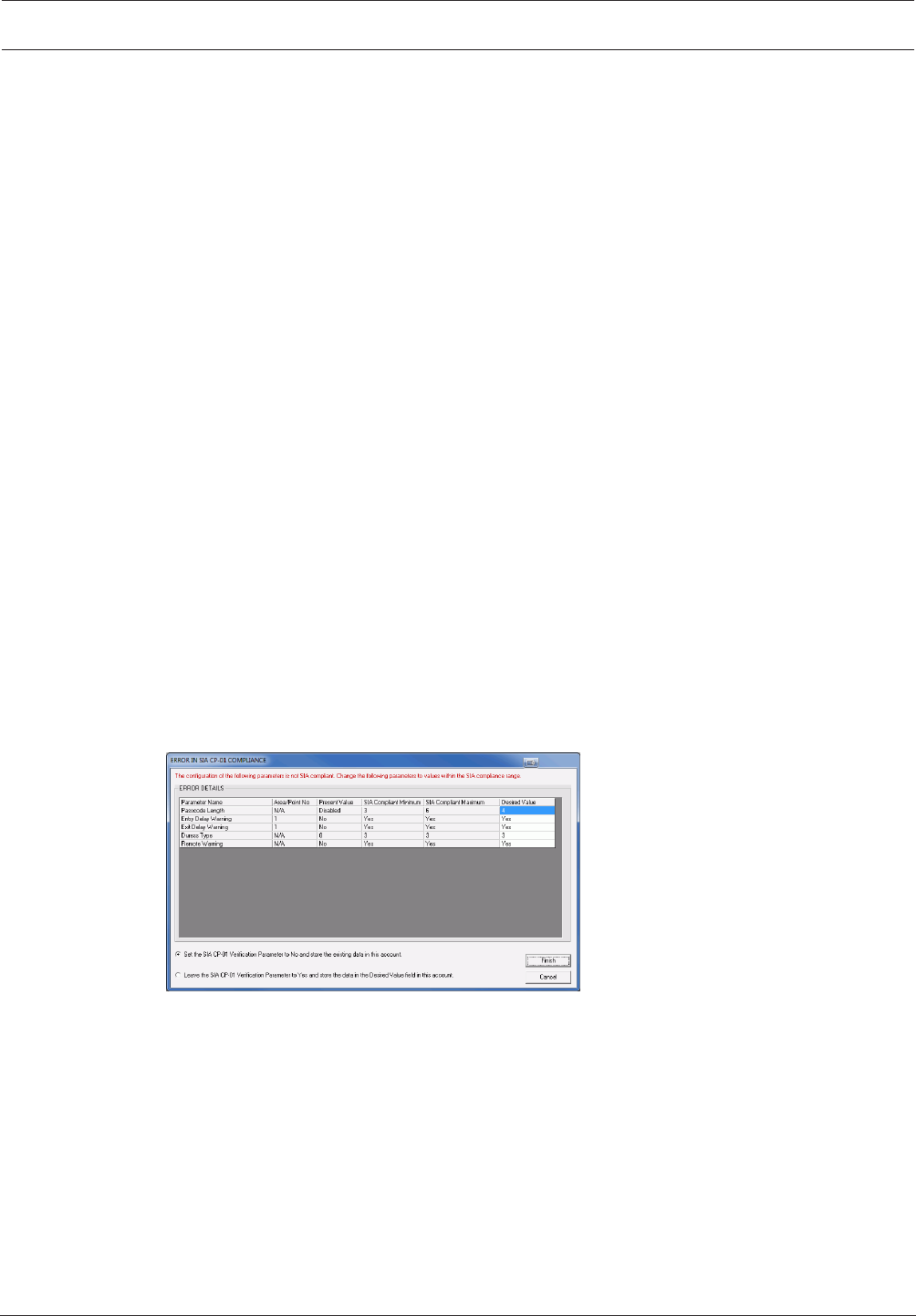
This parameter specifies whether or not this control panel requires SIA CP-01 False Alarm
Reduction compliance.
If RPS receives programming data from the control panel that is not SIA CP-01-compliant, the
SIA CP-01 Compliance window opens. Parameters that are out of compliance are listed.
Making the parameters SIA CP-01 compliant:
1. Enter a value under the Desired Value column that is between the compliant SIA minimum
and maximum values.
2. Select one of the following options:
– Set the SIA CP-01 Verification to No and store the existing data in this account.
– Leave the SIA CP-01 Verification Parameter to Yes and store the data in the Desired
Value field in this account.
If a control panel account contains parameters that do not comply with SIA CP-01, and you
retrieve that data using the Unattended Mode feature, RPS stores the non-compliant data
regardless of the SIA CP-01 parameter's setting.

18 en | Compliance Settings Control Panel
2017.03 | 03 | F.01U.323.389 Program Entry Guide Bosch Security Systems, Inc.
For each of the SIA CP-01-compliant parameters, ensure that the Minimum View and Edit
Security Levels match the minimum settings for this parameter. For example, if this
parameter's minimum view and edit security levels are 5, each compliant parameter must have
its levels set to 5.
RPS Menu Location
Compliance Verification > SIA CP-01 Verification
2.2 ULC Compliance
Default: No
Selections:
– Yes. Adjust control panel operation for UL Canada (ULC) compliance.
– No. Do not adjust for ULC compliance.
This parameter causes the control panel to disregard input from all sensors for a minimum of
120 seconds at system start-up.
When sensor processing is started, the control panel reports a unique event prior to reporting
any point events. Additionally, no power-induced events are reported unless it is determined
that the fault will not be restored within the 120 second delay time.
RPS Menu Location
Compliance Settings > ULC Compliance
2.2.1 CAN/ULC-S304 compliance
CAN/ULC-S304, SIGNAL RECEIVING CENTRE AND PREMISE BURGLAR ALARM CONTROL
UNITS
This Standard covers construction and performance requirements for control units and
accessories for intrusion alarm systems, including protected premises control units and
accessories for local or signal receiving centre connections, and signal receiving centre alarm
receiving equipment, including recording equipment. The equipment is intended for use in
premises, safes and vaults.
Control panel programming requirements
Setting the ULC Compliance parameter to Yes is the one control panel programming
requirement for compliance with the CAN/ULC-S304 standard.
2.2.2 CAN/ULC-S559, Required Programming
CAN/ULC-S559, Standard for Equipment for Fire Signal Receiving Centres and Systems
CAN/ULC-S559 covers requirements for fire signal receiving centres and systems, which
include transmitting and receiving equipment, proprietary fire receiving centre equipment and
control unit accessories. Fire signal receiving centre systems include protected premise unit
and receiver for ordinary (non-hazardous) indoor and outdoor locations. Programming
methods, test, service and other software intended for use with the equipment for fire signal
receiving centres and systems are included in the evaluation of the equipment. Signal
receiving units used in fire signal receiving centres, satellite centres, signal processing centres
and bridging centres are also covered by the requirements in this Standard.
COMPLIANCE SETTINGS > UL Canada Compliance
Set the COMPLIANCE SETTINGS > UL Canada Compliance parameter to Yes.
PANEL WIDE PARAMETERS > Report Routing
In the Route Group 4 column:
– Set Fire Reports, Gas Reports, Burglar Reports, Personal Emergency Reports, User
Reports, and Test reports to No.
Control Panel Compliance Settings | en 19
Bosch Security Systems, Inc. Program Entry Guide 2017.03 | 03 | F.01U.323.389
– Set Output Reports, Auto Function Reports, RPS Reports, Point Reports, User Change
Reports, and Access Reports to No.
– Verify Diagnostic Reports is set to Custom. The next steps configure the Custom settings.
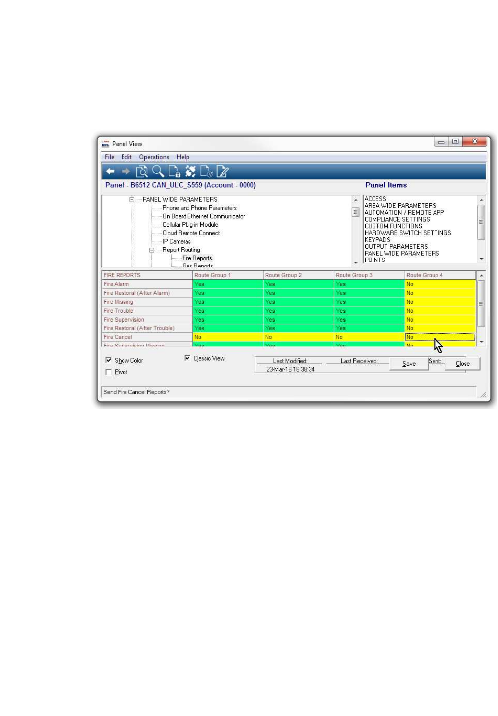
PANEL WIDE PARAMETERS > Report Routing > Fire Reports > Fire Cancel
Set the PANEL WIDE PARAMETERS > Report Routing > Fire Reports > Fire Cancel parameter
for each Route Group (1 to 4) to No.
Figure2.1: Fire Cancel
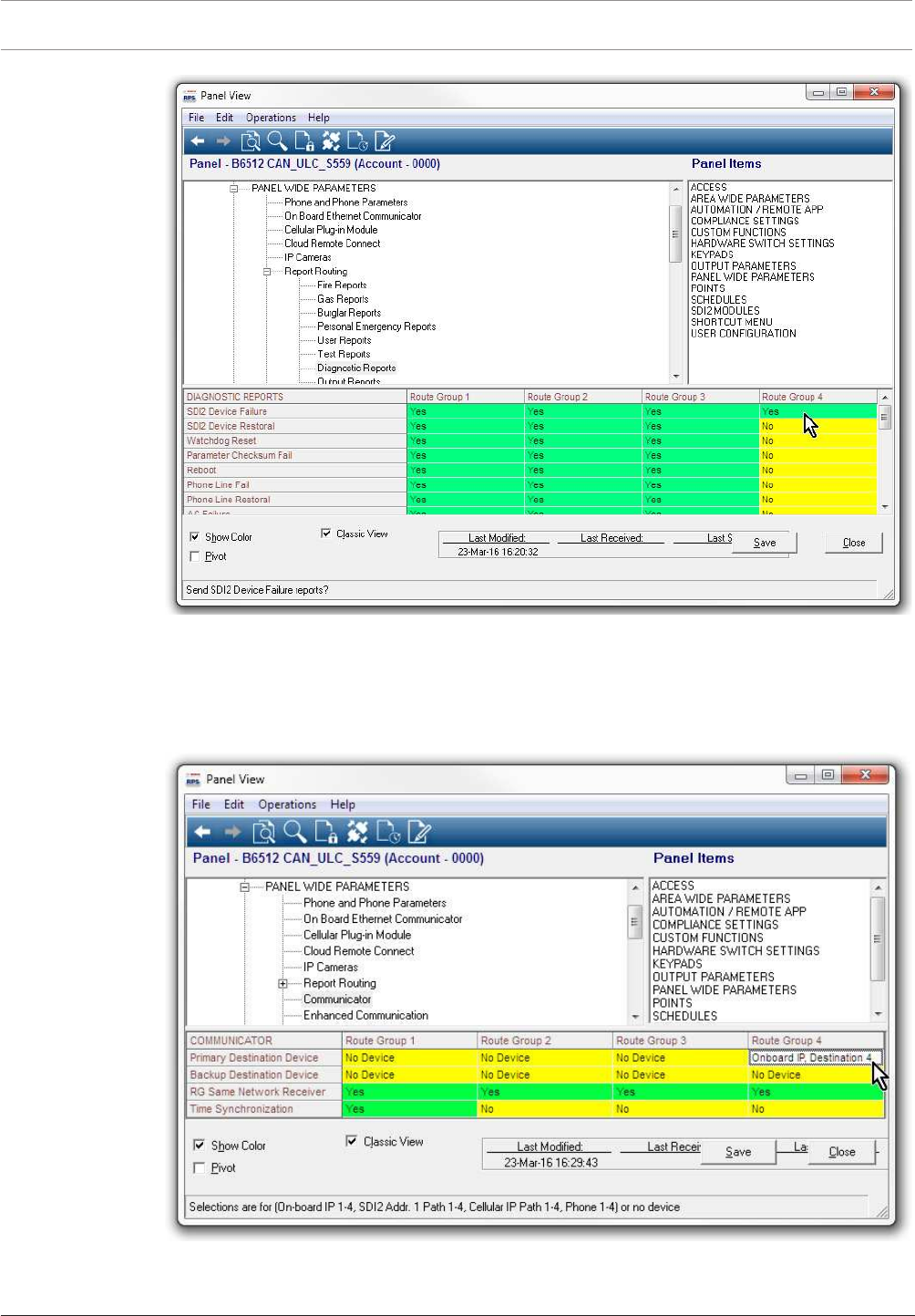
PANEL WIDE PARAMETERS > Report Routing > Diagnostic Reports
For the Route Group 4 column, set SDI2 Device Failure to Yes. Set the remaining reports to
No.
20 en | Compliance Settings Control Panel
2017.03 | 03 | F.01U.323.389 Program Entry Guide Bosch Security Systems, Inc.
Figure2.2: SDI2 Device Failure
PANEL WIDE PARAMETERS > Communicator > Primary Destination Device
For the Route Group 4 column, set Primary Destination Device to Destination 4 for the type of
device in use (for example, Onboard IP, Destination 4 if the control panel sends reports using
the on-board Ethernet.
Figure2.3: Primary Destination Device

Control Panel Compliance Settings | en 21
Bosch Security Systems, Inc. Program Entry Guide 2017.03 | 03 | F.01U.323.389
PANEL WIDE PARAMETERS > Enhanced Communication > Destination 4
In the Destination 4 column, set Network Address to: 0.1.1.1 (this address is intentionally not
a real address on the network). Set the Poll Rate to 0. Set the ACK Wait Time (sec.) to 5.
POINTS > Point Profiles (Point Indexes)
Configure Point Profiles 1, 4, and 6 as shown below.
It is important to configure the parameters in order.
Point Profile 1
Set Alarm Abort to: No.
Set Point Profile Text (First Language) to: Fire Panel Trouble.
Set PointType/Response/Circuit Style > PointType to: FirePoint.
Set PointType/Response/Circuit Style > Circuit Style to: SingleEOL(1KΩ) or
SingleEOL(2KΩ).
Set Response to: 3.
Point Profile 4
Set Point Profile Text (First Language) to: Fire Panel Alarm.
Set PointType/Response/Circuit Style > PointType to: FirePoint.
Set PointType/Response/Circuit Style > Circuit Style to: SingleEOL(1KΩ),
SingleEOL(2KΩ), or DualEOL.
If you set PointType/Response/Circuit Style > Circuit Style to SingleEOL(1KΩ) or
SingleEOL(2KΩ), set Response to: 1.
If you set Point Type / Response / Circuit Style > Circuit Style to DualEOL, set Response to: 0.
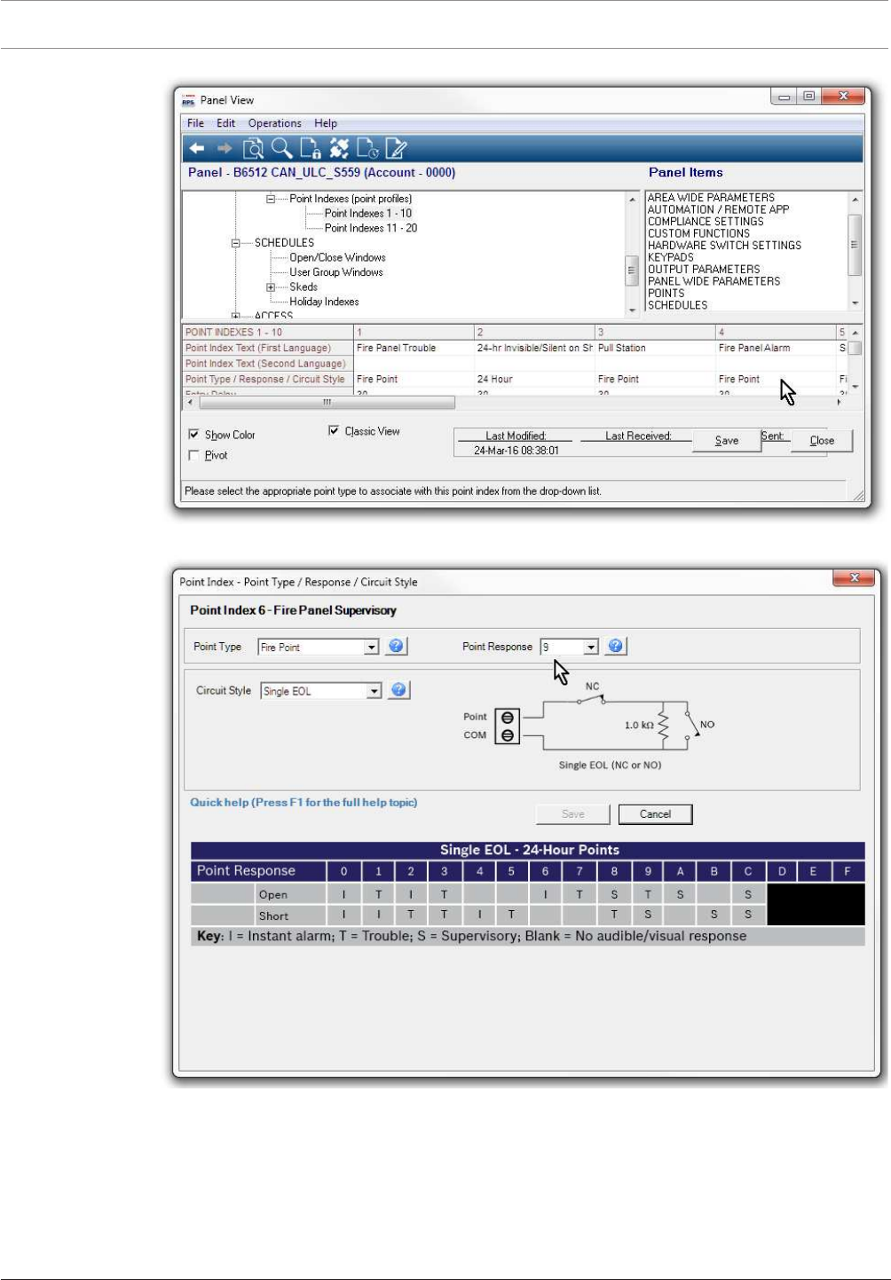
Point Profile 6
Set Point Profile Text (First Language) to: Fire Panel Supervisory.
Set PointType/Response/Circuit Style > PointType to: FirePoint.
Set PointType/Response/Circuit Style > Circuit Style to: SingleEOL(1KΩ),
SingleEOL(2KΩ), or DualEOL.
If you set PointType/Response/Circuit Style > Circuit Style to SingleEOL(1KΩ) or
SingleEOL(2KΩ), set Response to: 9.
If you set Point Type / Response / Circuit Style > Circuit Style to DualEOL, set Response to: 2.
22 en | Compliance Settings Control Panel
2017.03 | 03 | F.01U.323.389 Program Entry Guide Bosch Security Systems, Inc.
Figure2.4: Point Profiles
Figure2.5: Point Type Response and Circuit Style
POINTS > Point Assignments
Set the POINTS > Point Assignments, Text and Profile parameters, for on-board points 1, 2,
and 3 as follows.
Point 1
Set Point Assignments > Text to: Fire Panel Alarm.
Set Point Assignments > Profile to: 4 - Fire Panel Alarm
Control Panel Compliance Settings | en 23
Bosch Security Systems, Inc. Program Entry Guide 2017.03 | 03 | F.01U.323.389
Point 2
Set Point Assignments > Text to: Fire Panel Trouble.
Set Point Assignments > Profile to: 1 - Fire Panel Trouble
Point 3
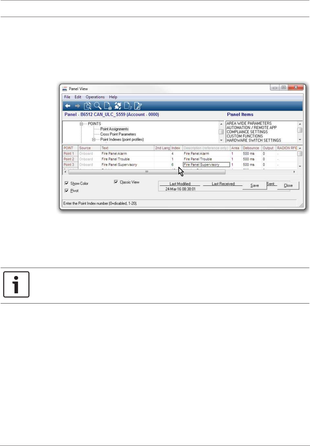
Set Point Assignments > Text to: Fire Panel Supervisory.
Set Point Assignments > Profile to: 6 - Fire Panel Supervisory
Figure2.6: Fire Panel Supervisory
2.2.3 CAN/ULC-S559, Recommended Programming
Control panel silencing of fire alarm panel alarm, trouble, and supervisory events
When control panels are configured as described below, they automatically silence keypads
connected to the control panel for fire, trouble, and supervisory events from the fire panel.
Notice!
Automatic silence not available for B3512 control panels
Automatic silencing of fire alarm panel alarm, trouble, and supervisory events is not available
for the B3512 control panel. Users must silence these events at the keypad.
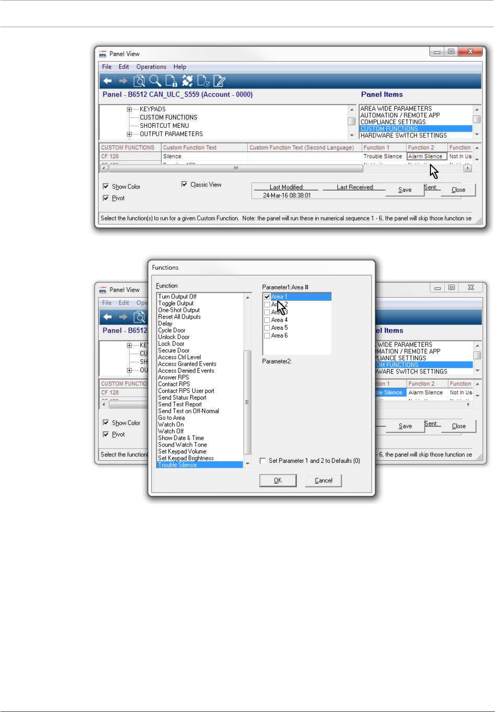
CUSTOM FUNCTIONS > Custom Function 128
Set Custom Function 128 > Custom Function Text to: Silence.
Set Custom Function 128 > Function 1 to: Trouble Silence (set Parameter 1 to: Area 1).
Set Custom Function 128 > Function 2 to: Alarm Silence (set Parameter 1 to: Area 1).
24 en | Compliance Settings Control Panel
2017.03 | 03 | F.01U.323.389 Program Entry Guide Bosch Security Systems, Inc.
Figure2.7: Custom Function 128
Figure2.8: Area 1 selection
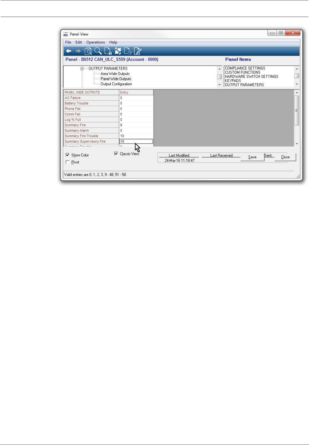
OUTPUT PARAMETERS > Panel Wide Outputs
For virtual outputs:
Set Panel Wide Outputs > Summary Fire to: 9.
Set Panel Wide Outputs > Summary Fire Trouble to: 10.
Set Panel Wide Outputs > Summary Supervisory Fire to: 19.
Control Panel Compliance Settings | en 25
Bosch Security Systems, Inc. Program Entry Guide 2017.03 | 03 | F.01U.323.389
Figure2.9: Panel Wide Outputs
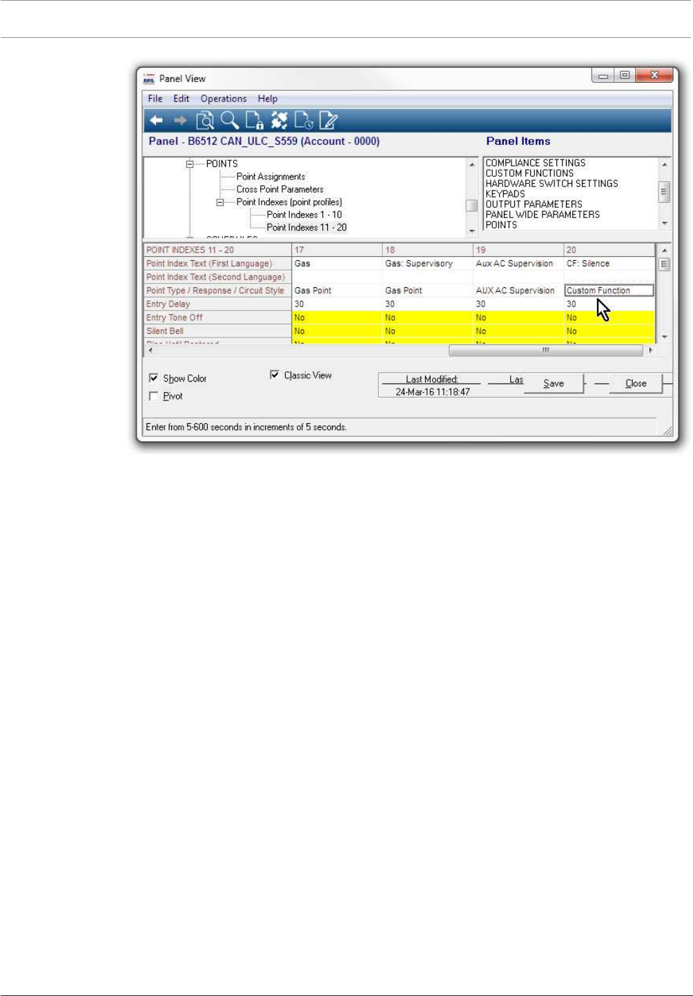
POINTS > Point Profiles (Point Indexes)
Configure Point Profile 20 as shown below.
It is important to configure the parameters in order.
Point Profile 20
Set Point Profile Text (First Language) to: CF: Silence.
Set PointType/Response/Circuit Style > PointType to: Custom Function.
Leave PointType/Response/Circuit Style > Circuit Style at the default: SingleEOL(1KΩ).
Leave PointType/Response/Circuit Style > Response at the default: 7.
26 en | Compliance Settings Control Panel
2017.03 | 03 | F.01U.323.389 Program Entry Guide Bosch Security Systems, Inc.
Figure2.10: Point Profile 20
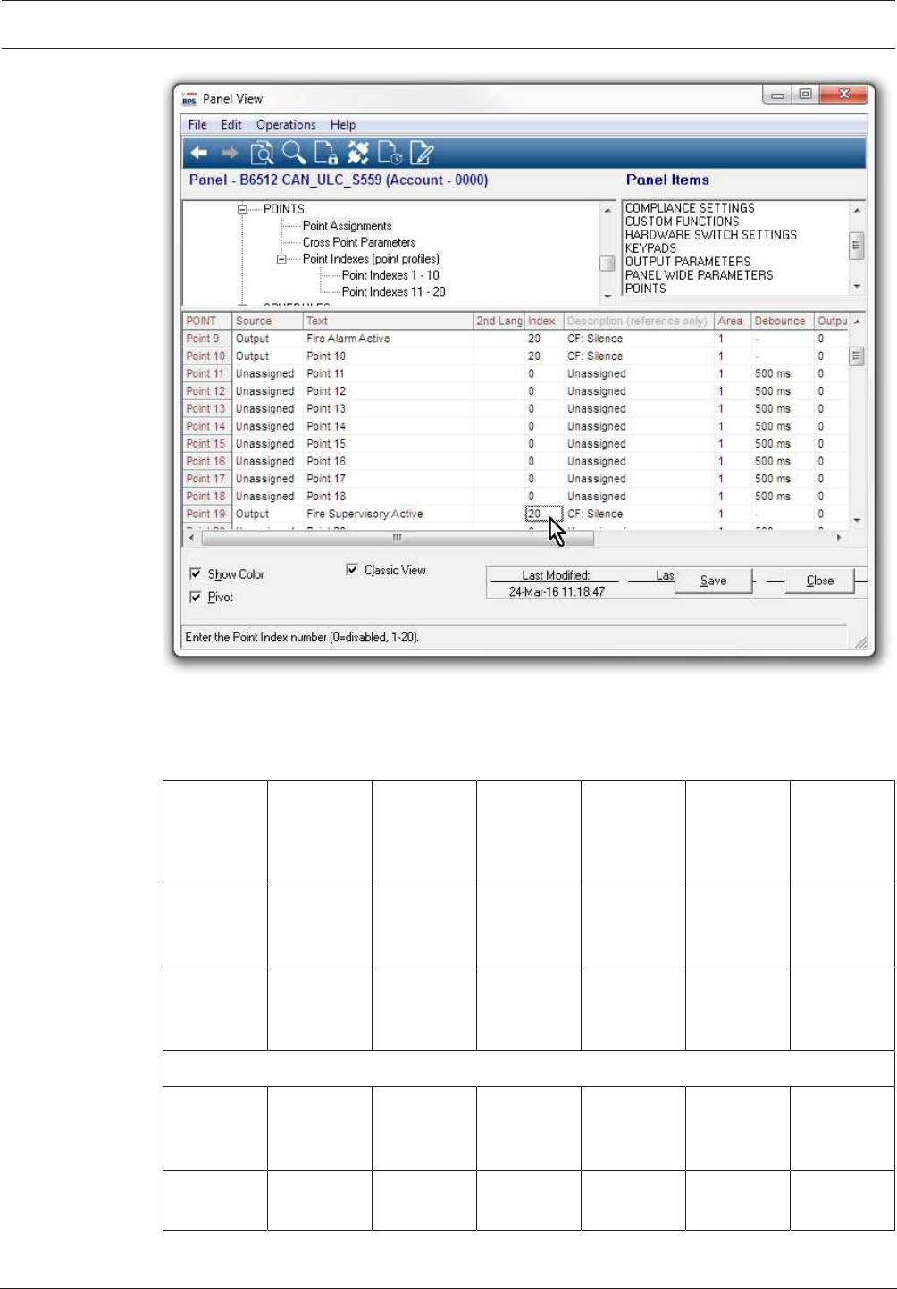
POINTS > Point Assignments
Set the POINTS > Point Assignments, Source, Text, and Profile parameters, for points 9, 10,
and 19 as follows.
Point 9
Set Point Assignments > Source to: Ouput.
Set Point Assignments > Text to: Fire Alarm Active.
Set Point Assignments > Profile to: 20 - CF: Silence
Point 10
Set Point Assignments > Source to: Ouput.
Set Point Assignments > Text to: Fire Trouble Active.
Set Point Assignments > Profile to: 20 - CF: Silence
Point 19
Set Point Assignments > Source to: Ouput.
Set Point Assignments > Text to: Fire Supervisory Active.
Set Point Assignments > Profile to: 20 - CF: Silence
Control Panel Compliance Settings | en 27
Bosch Security Systems, Inc. Program Entry Guide 2017.03 | 03 | F.01U.323.389
Figure2.11: Point Assignments
2.3 Supervision configuration
Optimizing data used for supervision:
Installation
Type
Commercial
Burg
(UL1610)
Commercial
Burg (ULC
S304)
High
Supervision
Hourly Medium
Security or
Household
Fire
Daily
Supervision
Required
Supervision
Interval
200 sec 180 sec 300 sec 1 hr 4 hr 25 hr
Recommen
ded Service
Plan
Extended Extended High
Supervision
Standard Standard Backup
Panel Programming
Receiver
Supervision
Time
200 sec Custom 300 sec 1 hr – NFPA 4 hr –
Medium
Security
25 hr
Panel Poll
Rate (sec)
n/a 89 sec n/a n/a n/a n/a

28 en | Compliance Settings Control Panel
2017.03 | 03 | F.01U.323.389 Program Entry Guide Bosch Security Systems, Inc.
Installation
Type
Commercial
Burg
(UL1610)
Commercial
Burg (ULC
S304)
High
Supervision
Hourly Medium
Security or
Household
Fire
Daily
Supervision
Panel ACK
Wait (sec)
n/a 15 n/a n/a n/a n/a
Panel Retry
Count
n/a 5 n/a n/a n/a n/a

Control Panel Panel Wide Parameters | en 29
Bosch Security Systems, Inc. Program Entry Guide 2017.03 | 03 | F.01U.323.389
3 Panel Wide Parameters
3.1 Phone and Phone Parameters
3.1.1 Phone Destination 1 (to 4)
Default:Blank
Selections:
– Blank - the control panel dials no phone number. Leaving this parameter blank does not
disable the Phone Destination. To prevent use of the phone destination, do not assign it
to a Communicator, overview, page 58.
– 0-9 - the control panel dials these characters.
– C - inserts a 2 second pause in the dialing sequence. Some telephone networks may
require a pause during or immediately after dialing. To insert a pause, insert one or more
C's in the dialing sequence.
– D - the control panel begins dialing when a dial tone is detected, or when the initial 7-
second dial tone detect period expiries. To extend the dial tone detect period, insert a D
at the beginning of the dialing sequence (before the phone number).
– # and * - inserting these characters in the dialing sequence performs the same function as
if they were pressed on a telephone keypad. For example, if you need a star (*) to access
your long distance service.
This parameter sets the telephone number the control panel dials to send reports to the
central station receiver.
Configuring Phone Destinations for Call Waiting
Dialing a call waiting sequence on a non-call waiting line prevents the system from
successfully sending reports to the central station receiver.
If you configure a Phone Destination with a phone number that includes a sequence to cancel
call waiting and choose that Phone Destination as the Primary Destination Device, page 59 for
a Route Group,
configure another Phone Destination without the call waiting cancel sequence and choose it
as the Backup Destination Device, page 60 Device for the Route Group.
If the customer cancels call waiting service without notifying their security company, the
control panel is still able to send reports using the Backup Destination Device.
RPS Menu Location
Panel Wide Parameters > Phone and Phone Parameters > Phone Destination 1 to 4
3.1.2 Phone Destination 1 (to 4) Format
Default:Modem4
Selections:
– Modem4 - the control panel sends expanded Modem4 reports to the central station
receiver.
– Contact ID - use this format when the central station receiver does not support the
Modem4 format.
This parameter sets the format for sending reports to the central station receiver.
Both Modem4 and Contact ID formats include point and user numbers in the reports sent to
the receiver. Only Modem4 reports include expanded information including point text.
RPS Menu Location
Panel Wide Parameters > Phone and Phone Parameters > Phone Destination (1 to 4) Format
3.1.3 DTMF Dialing
Default:Yes
Selections:

30 en | Panel Wide Parameters Control Panel
2017.03 | 03 | F.01U.323.389 Program Entry Guide Bosch Security Systems, Inc.
– Yes - the control panel dials phone numbers using DTMF (dual-tone multi-frequency,
touch-tone).
– No - the control panel dials phone numbers using pulse dialing.
Before setting this parameter to No, verify the PSTN (Public Switch Telephone Network) the
control panel is connected to supports pulse dialing.
RPS Menu Location:
Panel Wide Parameters > Phone and Phone Parameters > DTMF Dialing
3.1.4 Phone Supervision Time
Default:0
Selections:
– 0 - disabled, no phone line supervision.
– 10-240 (seconds) - number of seconds (in 10 second increments) a phone line must be
faulted before the control panel creates a phone line fail event.
The control panel tests the phone line approximately nine times a minute. If it detects a fault
on the phone line that lasts the number of seconds set at this parameter, it creates a phone
line fail event.
Keypads display phone line fail event and initiate a trouble tone if the Buzz on Fail, page 30
and Trouble Tone, page 113 parameters are set to Yes. If the Alarm on Fail, page 30 parameter
is set to Yes, keypads display an alarm event and sound the alarm tone.
When the control panel detects a normal phone line (fault is cleared) for the number of
seconds set at this parameter, it creates a phone line restoral event.
The control panel sends phone line fail and phone line restoral reports when the events occur.
They are also included in Expand Test Report, page 31 initiated from a keypad or by a Skeds,
page 210.
Phone line fail events are assigned to Area 1 and use the Area 1 configuration. For example,
the Area 1 account number is used for reporting.
RPS Menu Location
Panel Wide Parameters > Phone and Phone Parameters > Phone Supervision Time
3.1.5 Alarm on Fail
Default:No
Selections:
– Yes - initiate an alarm response for phone line fail events.
– No -. initiate an alarm response for phone line fail events
To use this Alarm on fail feature, enable phone line supervision at the Phone Supervision Time,
page 30 parameter.
The alarm response for phone line fail events includes:
– activating the Area 1 Burglar Bell,
– activating the alarm tone at keypads
– sending alarm reports
RPS Menu Location
Panel Wide Parameters > Phone and Phone Parameters > Alarm on Fail
3.1.6 Buzz on Fail
Default:No
Selections:
– Yes - the control activates a panel-wide trouble tone at all keypads when a phone line fail
event occurs.

Control Panel Panel Wide Parameters | en 31
Bosch Security Systems, Inc. Program Entry Guide 2017.03 | 03 | F.01U.323.389
– No - the control does not activate the trouble tone at any keypad when a phone line fail
event occurs.
To use this Buzz on fail feature, enable phone line supervision at the Phone Supervision Time,
page 30 parameter.
Panel-wide trouble tones are enabled and disabled for individual keypads at their Trouble
Tone parameter (Trouble Tone, page 113). The default for the Trouble Tone parameter for all
keypads is No (panel wide troubles do not sound).
RPS Menu Location
Panel Wide Parameters > Phone and Phone Parameters > Buzz On Fail
3.1.7 Expand Test Report
Default:No
Selections:
– Yes - Send expanded test reports.
– No - Do not send expanded test reports.
When this parameter is set to Yes, the control panel expands test reports to include off-normal
system status information.
The control panel expands manually initiated test reports and Sked initiated (scheduled) test
reports.
RPS Menu Location
Panel Wide Parameters > Phone and Phone Parameters > Expand Test Report
3.1.8 PSTN Compatibility
Default:USA
Selections:
– USA
– Australia
– New Zealand
This parameter configures the control panel and the B430 Plug-in Telephone Communicator to
support public switched telephone networks (PSTN) in the USA, Australia, or New Zealand.
Notice!
PSTN requirement for Australia / New Zealand, disable RPS answer armed/disarmed
If you set this PSTN Compatibility parameter to Australia or New Zealand, you must set
PanelWideParameters > RPSParameters > AnswerArmed and AnswerDisarmed to 0
(disabled).
RPS Menu Location
Panel Wide Parameters > Phone and Phone Parameters > PSTN Compatibility
3.2 On Board Ethernet (IP) Communicator
3.2.1 IPv6 Mode
Default: No
Selections:
– Yes - Enable IPv6
– No - Disable IPv6 (Use IPv4 mode).
This parameter configures IP communication for IPv6 (Internet Protocol version 6) or IPv4
(Internet Protocol version 4)
When IPv6 Enable is set to Yes, the IPv4 parameters are read only (grayed out and not
editable). Set DHCP/AutoIP enable to Yes.

32 en | Panel Wide Parameters Control Panel
2017.03 | 03 | F.01U.323.389 Program Entry Guide Bosch Security Systems, Inc.
When IPv6 Enable is set to No, the IPv6 parameters are read only (grayed out and not
editable).
RPS Menu Locations
Panel Wide Parameters > Onboard Ethernet Communicator > IPv6 Mode,
3.2.2 IPv4 DHCP/AutoIP Enable
Default: Yes
Selections:
– Yes - enable DHCP to automatically configure the IP Address, IP Default Gateway, and IP
DNS Server Address.
– No - manually configure the IP Address, IP Default Gateway, and IP DNS Server Address.
Use this setting if there is no DHCP service.
DHCP enables a computer to be automatically configured which eliminates the need for
interaction by a network administrator. DHCP also provides a central database that tracks
computers that connect to the network, which prevents two computers from accidentally
being configured with the same IP address.
AutoIP enables dynamic IP addresses to be assigned to a device when the device is started up.
DHCP requires a DHCP server.
When this parameter is set to Yes, the IPv4 address, IPv4 Subnet Mask, and IPv4 Default
Gateway are grayed out. You cannot change them.
When this parameter is set to No, set the IPv6 Mode parameter to No. When the IPv6 Mode
parameter is set to Yes, this parameter is not available (grayed out).
RPS Menu Locations
Panel Wide Parameters > Onboard Ethernet Communicator > IPv4 DHCP/AutoIP Enable
3.2.3 IPv4 Address
Default: 0.0.0.0
Selections: 0.0.0.0 to 255.255.255.255
This parameter sets the IPv4 address.
If the IPv4 DHCP/Auto IP Enable parameter is set to Yes, this parameter is grayed out (you do
not have access to it).
If the IPv4 DHCP/Auto IP Enable parameter is set to No, enter the IPv4 address here.
Further Information
IP Address and Domain Name formats, page 254
RPS Menu Location
Panel Wide Parameters > Onboard Ethernet Communicator > IPv4 address
3.2.4 IPv4 Subnet Mask
Default: 255.255.255.0
Selections: 0.0.0.0 to 255.255.255.255
This parameter sets the address for the IPv4 Subnet Mask.
If the IPv4 DHCP/Auto IP Enable parameter is set to Yes, this parameter is grayed out (you do
not have access to it).
If the IPv4 DHCP/Auto IP Enable parameter is set to No, enter the IPv4 sub-network mask
here.
Subnetting breaks the network into more efficient subnets to prevent the excessive rates of
packet collision in a large network. A significant feature of subnets is the subnet mask.
Applying a subnet mask to an IP address allows control panels to more efficiently identify the
network and node parts of the address.

Control Panel Panel Wide Parameters | en 33
Bosch Security Systems, Inc. Program Entry Guide 2017.03 | 03 | F.01U.323.389
Further information
IP Address and Domain Name formats, page 254
RPS Menu Locations
Panel Wide Parameters > Onboard Ethernet Communicator > IPv4 Subnet Mask
3.2.5 IPv4 Default Gateway
Default: 0.0.0.0
Selections: 0.0.0.0 to 255.255.255.255
This parameter sets the address for the local network gateway to the internet or intranet.
If the IPv4 DHCP/Auto IP Enable parameter is set to Yes, this parameter is grayed out (you do
not have access to it).
If the IPv4 DHCP/Auto IP Enable parameter is set to No, enter the Default Gateway address
here.
A gateway is an address on a TCP/IP network that serves as an entrance to another network. A
host uses a default gateway when an IP packet's destination is outside the local subnet. The
default gateway address is usually an interface belonging to a LAN's border router.
Further information
IP Address and Domain Name formats, page 254
RPS Menu Locations
Panel Wide Parameters > Onboard Ethernet Communicator > IPv4 Default Gateway4 Default
Gateway
3.2.6 IPv4 DNS Server IP Address
Default: 0.0.0.0
Selections: 0.0.0.0 to 255.255.255.255
This parameter sets the IPv4 DNS server address in Static IP mode.
A Domain Name Server (DNS) converts internet domain names or hostnames to their
corresponding IP addresses. In DHCP mode, the DHCP server’s default DNS is used. To use a
custom DNS server in DHCP mode, change this parameter to the custom DNS server’s IP
address.
Further information
IP Address and Domain Name formats, page 254
RPS Menu Locations
Panel Wide Parameters > Onboard Ethernet Communicator > IPv4 DNS server IP address
3.2.7 IPv6 DNS Server IP Address
Default: ::
Selections: 0000:0000:0000:0000:0000:0000:0000:0000 to
FFFF:FFFF:FFFF:FFFF:FFFF:FFFF:FFFF:FFFF
This parameter configures the IPv6 DNS server address in Static IP mode.
A Domain Name Server (DNS) converts internet domain names or hostnames to their
corresponding IP addresses. In DHCP mode, the DHCP server’s default DNS is used. To use a
custom DNS server in DHCP mode, change the parameter to the custom DNS server’s IP
address.
When this address is set by the DHCP service, do not change it.
This IPv6 DNS server address is the only IPv6 address entered as numbers.
Further information
IP Address and Domain Name formats, page 254
RPS Menu Locations
Panel Wide Parameters > Onboard Ethernet Communicator > IPv6 DNS server IP address

34 en | Panel Wide Parameters Control Panel
2017.03 | 03 | F.01U.323.389 Program Entry Guide Bosch Security Systems, Inc.
3.2.8 UPnP (Universal Plug and Play) Enable
Default: Yes
Selections:
– Yes – open port forwarder using UPnP
– No – do not use UPnP.
When this parameter is set to Yes, the control panel sends a request to the premises router to
open a port forwarder. The port forward allows inbound RPS and RSC (Remote Security
Control) connections.
The UPnP parameter has no effect on event reporting to a central station receiver.
Notice!
UPnP requires IP Address / Host Name and Panel Port be configured
In the Panel Data – View, Network tab, verify that the IP Address / Host Name and Panel Port
parameters are configured.
RPS Menu Locations
Panel Wide Parameters > Onboard Ethernet Communicator > UPnP (Universal Plug and Play)
Enable
3.2.9 ARP Cache Timeout (sec.)
Default: 600
Selections: 1 to 600 (seconds)
This parameter specifies the time-out for ARP cache entries (time-out value in seconds).
RPS Menu Locations
Panel Wide Parameters > Onboard Ethernet Communicator > ARP Cache Timeout
3.2.10 Module Hostname
Default: Blank
Selections: Up to sixty-three characters (letters, numbers, and dashes)
The hostname indentifies the ip communicator (onboard or SDI2 module) on the network. Use
this parameter to create a custom hostname.
Notice!
Leave this parameter blank to use factory default hostname
The factory default hostname begins with the letter B, followed by the last six digits of the
modules MAC address.
Use RPS diagnostics or installer (keypad) diagnostics to view the hostname.
Use the hostname on a local network using DHCP. To use the hostname externally, you must
enter the hostname in the DNS server.
You can use the hostname to connect to the control panel with RPS or RSC (Remote Security
Control), or for module web configuration and diagnostics.
RPS Menu Location
Panel Wide Parameters > Onboard Ethernet Communicator > Module Hostname
3.2.11 TCP / UDP Port Number
Default: 7700
Selections: 0 - 65535
This parameter sets the local port number that the IP communicator listens to in-coming
network traffic. It also uses this port for outgoing communications.
The TCP/UDP Port is typically left at the default, 7700, for control panel communications with
a central station receiver, RPS, automation, or Remote Security Control (RSC).

Control Panel Panel Wide Parameters | en 35
Bosch Security Systems, Inc. Program Entry Guide 2017.03 | 03 | F.01U.323.389
Port numbers are categorized into three ranges:
System ports 0-1023
User ports 1024-49151
Dynamic or private ports 49152-65535
Notice!
Limit unwanted traffic, choose a port number greater than 1023
In order reduce the risk of unwanted network traffic interfering with control panel IP
communications, select a port number above 1023.
RPS Menu Location
Panel Wide Parameters > Onboard Ethernet Communicator > TCP/UDP Port Number
3.2.12 TCP Keep Alive Time (sec.)
Default: 45
Selections: 0 - 65 (seconds)
This parameter sets the time in seconds between TCP keep-alive transmissions to verify that
an idle connection is still active.
RPS Menu Locations
Panel Wide Parameters > Onboard Ethernet Communicator > TCP Keep Alive Time (sec.)
3.2.13 IPv4 Test Address
Default: 8.8.8.8
Selections: IPv4 address or Domain Name
The default test address works for most networks.
The control panel uses the IP communicator to ping the IPv4 Test Address to verify the
integrity of the network and the network configuration settings.
Further information
IP Address and Domain Name formats, page 254
RPS Menu Locations
Panel Wide Parameters > Onboard Ethernet Communicator > IPv4 Test Address
3.2.14 IPv6 Test Address
Default: 2001:4860:4860::8888
Selections: IPv6 address or Domain Name
The default test address works for most networks.
This parameter is only available when IPv6 Mode is set to Yes.
The control panel uses the IP communicator to ping the IPv4 Test Address to verify the
integrity of the network and the network configuration settings.
Further information
IP Address and Domain Name formats, page 254
RPS Menu Location
Panel Wide Parameters > Onboard Ethernet Communicator > IPv6 Test Address.
3.2.15 Alternate IPv4 DNS server IP address
Default: 0.0.0.0
Selections: 0.0.0.0 to 255.255.255.255
This parameter provides an alternate IPv4 DNS server IP address.

36 en | Panel Wide Parameters Control Panel
2017.03 | 03 | F.01U.323.389 Program Entry Guide Bosch Security Systems, Inc.
If the IP communicator fails to obtain an address from the primary server, it tries the alternate
DNS server.
Further information
IP Address and Domain Name formats, page 254
RPS Menu Locations
Panel Wide Parameters > Onboard Ethernet Communicator > Alternate IPv4 DNS server
IP address
3.2.16 Alternate IPv6 DNS server IP address
Default: ::
Selections: 0000:0000:0000:0000:0000:0000:0000:0000 to
FFFF:FFFF:FFFF:FFFF:FFFF:FFFF:FFFF:FFFF
This parameter provides an alternate IPv6 DNS server IP address.
The Alternate IPv6 Domain Name Server (DNS) address has a hexadecimal notation, which
consists of the eight groups of the address expressed separately in hexadecimal and
separated by colons. Each group has a value between 0000-FFFF.
When this is defined through the DHCP service, leave the default value. If the module fails to
obtain an address from the primary server, the Alternate IPV6 DNS server is used, if specified.
The module can use the Alternate IPv6 DNS server only when the Primary address is not the
default address.
Further information
IP Address and Domain Name formats, page 254
RPS Menu Locations
Panel Wide Parameters > Onboard Ethernet Communicator > Alternate IPv6 DNS server IP
address
3.3 Cellular Plug-in Module
3.3.1 Inbound SMS
Notice!
Important configuration information for cellular communication
Refer to Configuring for Cellular Service, page 252 for an overview and configuration
information.
Default: Yes
Selections:
Yes - Enabled
No - Disabled
This parameter enables an RPS user to start a control panel initiated download with an SMS
message.
RPS Menu Location
Panel Wide Parameters > Cellular Plug-in Module > Inbound SMSB450 Cellular > Inbound SMS
3.3.2 Session Keep Alive Period (min.)
Notice!
Important configuration information for cellular communication
Refer to Configuring for Cellular Service, page 252 for an overview and configuration
information.
Control Panel Panel Wide Parameters | en 37
Bosch Security Systems, Inc. Program Entry Guide 2017.03 | 03 | F.01U.323.389
Default: 0
Selections: 0 to 1000 (minutes)
– 0 - Disabled. Panel does not verify the connection is active.
– 1 to 1000 - Enabled. Panel verifies an active connection exists.
This parameter sets the length of time in minutes between session keep alive reports to verify
that an idle connection is still active. This parameter is pre-configured for optimal
performance. Leave at the default setting. Default settings should only be changed for high
security UL1610 commercial listed installations requiring low signal notification.
RPS Menu Location
Panel Wide Parameters > Cellular Plug-in Module > Session Keep Alive PeriodKeep Alive Period
3.3.3 Inactivity Timeout (min.)
Notice!
Important configuration information for cellular communication
Refer to Configuring for Cellular Service, page 252 for an overview and configuration
information.
Default: 0
Selections: 0 to 1000 (minutes)
– 0 - Disabled. Panel does not verify the connection is active.
– 1 to 1000 - Enabled. Panel verifies an active connection exists.
This parameter specifies the time before the control panel will disconnect a session with no
data traffic. This parameter is pre-configured for optimal performance. Leave at the default
setting. Default settings should only be changed for high security UL1610 commercial listed
installations requiring low signal notification.
RPS Menu Location
Panel Wide Parameters > Cellular Plug-in Module > Inactivity Timeout
3.3.4 Reporting Delay for Low Signal Strength (sec.)
Notice!
Important configuration information for cellular communication
Refer to Configuring for Cellular Service, page 252 for an overview and configuration
information.
Default: 0
Selections: 0-3600 (seconds)
– 0 - Disabled.
– 1 to 3600 - seconds of delay before Cellular Low Signal event.
Notice!
UL Requirement
To meet UL requirements, the entry for this parameter should not exceed 200 seconds.
The control panel creates a Cellular Low Signal event when the signal strength is below the
"unacceptable" threshold (indicated by the red LED) for the number of seconds specified in
this Reporting Delay for Low Signal Strength parameter. (Low signal is defined as 80% of the
measurements taken during the time period are below the threshold).
38 en | Panel Wide Parameters Control Panel
2017.03 | 03 | F.01U.323.389 Program Entry Guide Bosch Security Systems, Inc.
The control panel creates a Cellular Low Signal Restoral event when the signal strength is
above the "good" threshold (indicated by the green LED) for the number of seconds specified
in this Reporting Delay for Low Signal Strength parameter. (Good signal is defined as 80% of
the measurements taken during the time period are above the threshold).
RPS Menu Location
Panel Wide Parameters > Cellular Plug-in Module > Reporting Delay for Low Signal Strength
3.3.5 Reporting Delay for No Towers (sec.)
Notice!
Important configuration information for cellular communication
Refer to Configuring for Cellular Service, page 252 for an overview and configuration
information.
Default: 0
Selections: 0-3600 (seconds)
– 0 - Disabled.
– 1 to 3600 - Enabled.
When there are no towers present the control panel starts two timers, one for a
NoTowersevent, one for a NoIPAddress event. The control panel uses the duration set by
this ReportingDelayforNoTowerparameter for both timers. If the cellular plug-in module
does not find a tower before the end of the delay, the control panel creates a NoTowersevent
and a NoIPAddressevent at the same time.
The control panel creates a NoTowerrestoral event when one or more towers are available for
the duration set by this ReportingDelayforNoTowerparameter.
The contro panel creates a NoIPAddressrestoralevent when the cellular plug-in module
successfully registers with one or more towers and receives an IP address.
Notice!
When one or more towers are available, 60 second delay for NoIPAddressevent
If the cellular plug-in module successfully registers with one or more towers, but does not
receive an IP address within 60 seconds, the control panel creates a NoIPAddressevent.
RPS Menu Location
Panel Wide Parameters > Cellular Plug-in Module > Reporting Delay for No Towers
3.3.6 Outgoing SMS Length
Notice!
Important configuration information for cellular communication
Refer to Configuring for Cellular Service, page 252 for an overview and configuration
information.
Default: 160
Selections: 0 to 3600 (bytes)
– 0 - Disabled.
– 1 to 3600 - Outgoing SMS length (number of bytes)
This parameter sets the maximum length for outgoing messages.
Outgoing SMS messages are rejected if over this length. This maximum length must match the
maximum length set by the cellular provider that is transmitting the SMS message (for
example, Verizon).

Control Panel Panel Wide Parameters | en 39
Bosch Security Systems, Inc. Program Entry Guide 2017.03 | 03 | F.01U.323.389
RPS Menu Location
Panel Wide Parameters > Cellular Plug-in Module > Outgoing SMS Length
3.3.7 Network Access Point Name (APN)
Notice!
Important configuration information for cellular communication
Refer to Configuring for Cellular Service, page 252 for an overview and configuration
information.
Default: wyless.apn
Selections: 0-99 ASCII characters
This parameter sets the IP address for the network access point. Enter up to 99 alphanumeric
characters. The field is case sensitive.
RPS Menu Location
Panel Wide Parameters > Cellular Plug-in Module > Network Access Point Name
3.3.8 Network Access Point User Name
Notice!
Important configuration information for cellular communication
Refer to Configuring for Cellular Service, page 252 for an overview and configuration
information.
Default: Blank
Selections: 0-30 ASCII characters
This parameter specifies the user name for the Network Access Point.
Enter up to 30 alphanumeric characters. The field is case sensitive.
RPS Menu Location
Panel Wide Parameters > Cellular Plug-in Module > Network Access Point User Name
3.3.9 Network Access Point Password
Notice!
Important configuration information for cellular communication
Refer to Configuring for Cellular Service, page 252 for an overview and configuration
information.
Default: Blank
Selections: 0-30 ASCII characters
This parameter sets the password required to access the Network Access Point.
Enter up to 30 alpha-numeric characters. The password is case sensitive.
RPS Menu Location
Panel Wide Parameters > Cellular Plug-in Module > Network Access Point Password
3.3.10 SIM PIN
Notice!
Important configuration information for cellular communication
Refer to Configuring for Cellular Service, page 252 for an overview and configuration
information.
Default: Blank
40 en | Panel Wide Parameters Control Panel
2017.03 | 03 | F.01U.323.389 Program Entry Guide Bosch Security Systems, Inc.
Selections: 4-8 numbers
This is an optional parameter. This parameter is only necessary if the SIM card uses a PIN for
security.
The SIM PIN is hidden on the display and appears as asterisks (********) when entered. If an
invalid SIM PIN is entered, an event is logged in history. A report is sent only if the report
function is enabled. If no SIM PIN is required, you can leave the field blank.
RPS Menu Location
Panel Wide Parameters > Cellular Plug-in Module > SIM PIN
3.4 Cloud Remote Connect
3.4.1 Cloud Remote Connect (Ethernet)
Default:Enable
Selections:
– Enable
– Disable
Use this parameter to enable the Bosch Cloud-based Service, Remote Connect, for
communication via an Ethernet connection.
Notice!
Bosch Installer Services, Remote Connect subscription required
Before you can utilize Remote Connect for RPS or RSC connections you need to visit https://
installerservices.boschsecurity.com/ to sign up for Bosch Installer Services.
RPS Menu Location
Panel Wide Parameters > Cloud Remote Connect > Cloud Remote Connect via Ethernet
3.4.2 Cloud Remote Connect (Cellular)
Default:Disable
Selections:
– Enable
– Disable
Use this parameter to enable the control panel to use the Bosch Cloud-based Service, Remote
Connect, for communication via a Cellular connection.
Notice!
Bosch Installer Services, Remote Connect subscription required
Before you can utilize Remote Connect for RPS or RSC connections you need to visit https://
installerservices.boschsecurity.com/ to sign up for Bosch Installer Services.
Notice!
Bosch Installer Services, Bosch Cellular Service required
Before you can utilize cellular communication for reporting or for RPS or RSC connections
you need to visit https://installerservices.boschsecurity.com/ to sign up for Bosch Installer
Services.
RPS Menu Location
Panel Wide Parameters > Clould Remote Connect > Cloud Remote Connect via Ethernet
3.5 IP cameras
The B6512 supports Cameras 1 to 6.

Control Panel Panel Wide Parameters | en 41
Bosch Security Systems, Inc. Program Entry Guide 2017.03 | 03 | F.01U.323.389
3.5.1 Camera name
Default: Camera #
Selections: 0-32 characters
This parameter allows the user to enter a description for a Bosch IP camera. Enter up to 32
characters of text, numbers, and symbols.
RPS Menu Location
Panel Wide Parameters > IP Cameras > Camera Name
3.5.2 Camera name (second language)
Default: Blank
Selections: Enter up to 32 characters.
This parameter allows the user to enter a description for a Bosch IP camera. Enter up to 32
characters from the Latin-1 8-bit (ISO/IEC 8859-1) character set to describe the area.
First and Second languages are programmed during panel account setup in the Panel Data -
View window. Refer to Panel Data - View > Panel Info tab > Additional Info.
Language options are: English, Spanish, French and Portuguese.
RPS Menu Location
Panel Wide Parameters > IP Cameras > Camera Name (second language)
3.5.3 URL or IP address
Default: Blank
Selections: 0-128 ASCII characters
This parameter sets the URL or IP address for the Bosch IP camera.
The control panel or RSC application uses the URL or IP address to communicate with the
camera over a network.
RPS Menu Location
Panel Wide Parameters > IP Cameras > URL or IP Address
3.6 Bosch Connected Cameras
Products
– B6512 with on-board IP communicator
– All Bosch IP cameras
Applications
Bosch IP cameras are best for small commercial and residential applications where
conventional video integration hardware and applications are cost prohibitive.
Implementation
This control panel communicates with Bosch IP cameras using a low-level language (RCP+).
Configure compatible control panels to use Bosch IP cameras as inputs, outputs, or both.
Environment
Install compatible control panels and Bosch IP cameras on the same network (LAN).
Panel Configuration
Configure the control panel with each camera's IP address. RCP+ port #, Service password,
and Supervision period (sec) parameters configure network communication and supervision
with connected Bosch IP cameras.
Other panel configuration for using IP cameras
New Point Source option "IP Camera" (ref. Points > Point Assignments > Source)
New Output Source option "IP Camera" (ref. Output Parameters > Output Configuration >
Output Source)

42 en | Panel Wide Parameters Control Panel
2017.03 | 03 | F.01U.323.389 Program Entry Guide Bosch Security Systems, Inc.
3.6.1 RCP+ port #
Default: 1756
Selections: 0-65535
This parameter identifies the port number the Bosch IP camera listens to for RCP+ protocol.
Only change from the default, 1756, if an IP camera has been configured to listen on a
different port.
RPS Menu Location
Panel Wide Parameters > IP Cameras > Bosch Connected Camera > RCP+ Port #
3.6.2 Service password
Default: Blank
Selections: 0, 1-32 characters
0 = Disable feature
This parameter sets the password required to access the Bosch IP camera's data. The
password is case sensitive.
RPS Menu Location
Panel Wide Parameters > IP Cameras > Bosch Connected Camera > Service Password
3.6.3 Supervision period (sec.)
Default: 0
Selections: 0, 30-255 sec
0 = Disable supervision
This parameter sets the length of time the controlpanel monitors a missing Bosch IP camera
before reporting the camera as missing.
RPS Menu Location
Panel Wide Parameters > IP Cameras > Bosch Connected Camera > Supervision Period
3.7 Live (video)
Products
– B6512 with on-board IP communicator
– All Bosch IP cameras
– RSC (Remote Security Control)
Applications
Live video is best for small commercial and residential applications where conventional video
integration hardware and applications are cost prohibitive.
Implementation
This control panel communicates with Bosch IP cameras using a low-level language (RCP+).
Configure the control panels to use Bosch IP cameras as inputs, outputs, or both.
The device configuration is independent, but native.
Environment
Install control panels and Bosch IP cameras on the same network (LAN).
Panel Configuration
RSC uses the Port #, Use HTTPS?, User Name, and Password parameters to access video
images within the IP cameras.
3.7.1 Port #
Default: 80
Selections: 0-65535
Control Panel Panel Wide Parameters | en 43
Bosch Security Systems, Inc. Program Entry Guide 2017.03 | 03 | F.01U.323.389
This parameter assigns a port number for the destination the RSC application uses to
communicate with the camera and view live video feed.
If the live viewer URL is assigned to a router, configure the router with the value specified
here.
Notice!
When using HTTPS, set this parameter to 443.
The B6512 supports Cameras 1 to 6.
RPS Menu Location
Panel Wide Parameters > IP Cameras > Live (Video) > Port #
3.7.2 Use HTTPS?
Default: No
Selections:
Yes - Enable HTTPS
No - Disable HTTPS
Use this parameter to encrypt data for a secure network communications between the Bosch
IP camera and the RSC.
Set to "Yes" if the live viewer requires HTTPS.
Notice!
When using HTTPS, set Panel Wide Parameters > IP Cameras > Live (Video) > Port # to 443.
The B6512 supports Cameras 1 to 6.
RPS Menu Location
Panel Wide Parameters > IP Cameras > Live (Video) > Use HTTPS?
3.7.3 User Name
Default: live
Selection: Enter up to 32 characters.
This parameter specifies the user name that the RSC application uses to show video from the
camera.
The B6512 supports Cameras 1 to 6.
RPS Menu Location
Panel Wide Parameters > IP Cameras > Live (Video) > User Name
3.7.4 Password
Default: Blank
Selections: 0-32 characters
This parameter sets the password required by the RSC application to view video from the
camera. The password is case sensitive.
The B6512 supports Cameras 1 to 6.
RPS Menu Location
Panel Wide Parameters > IP Cameras > Live (Video) > Password
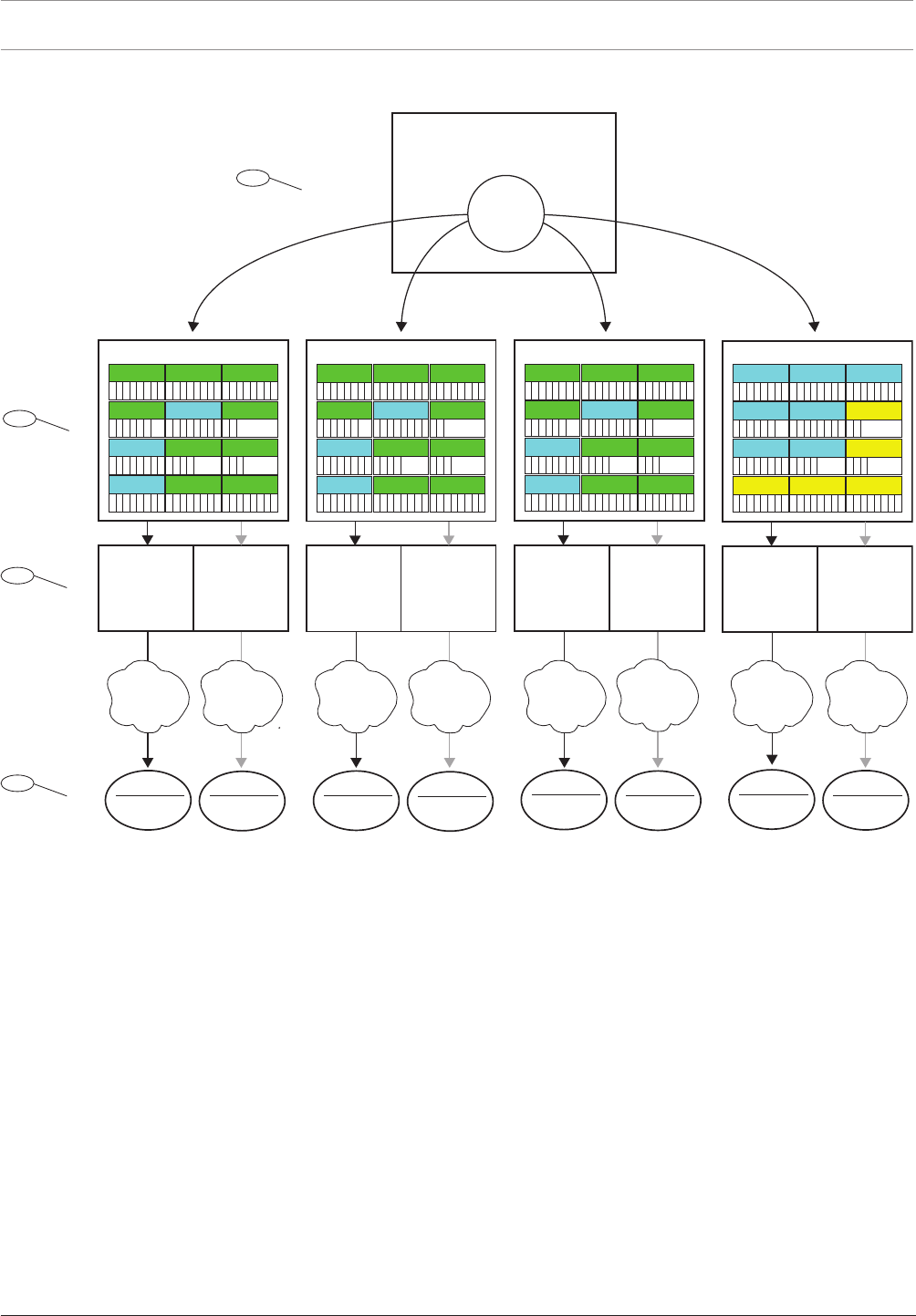
44 en | Panel Wide Parameters Control Panel
2017.03 | 03 | F.01U.323.389 Program Entry Guide Bosch Security Systems, Inc.
3.8 Reporting Overview
Primary
Destination
Device
Backup
Destination
Device
Test
xxxxxx
xxxxxx
Per Emer
xxxxxx
xxxxxx
xxxxxx
xxxxxx
xxxxxx
xxxxxx
Fire
xxxxxx
xxxxxx
xxxxxx
xxxxxx
xxxxxx
xxxxxx
xxxxxx
xxxxxx
Gas
xxxxxx
xxxxxx
xxxxxx
xxxxxx
xxxxxx
xxxxxx
xxxxxx
xxxxxx
Burglar
xxxxxx
xxxxxx
xxxxxx
xxxxxx
xxxxxx
xxxxxx
xxxxxx
xxxxxx
User
xxxxxx
xxxxxx
xxxxxx
xxxxxx
xxxxxx
xxxxxx
xxxxxx
xxxxxx
Usr Chng
xxxxxx
xxxxxx
xxxxxx
xxxxxx
xxxxxx
xxxxxx
xxxxxx
xxxxxx
RPS
xxxxxx
xxxxxx
xxxxxx
xxxxxx
xxxxxx
xxxxxx
xxxxxx
xxxxxx
Diag
xxxxxx
xxxxxx
xxxxxx
xxxxxx
xxxxxx
xxxxxx
xxxxxx
xxxxxx
Output
xxxxxx
xxxxxx
xxxxxx
xxxxxx
Auto Fnc
xxxxxx
xxxxxx
xxxxxx
Point
xxxxxx
xxxxxx
xxxxxx
xxxxxx
xxxxxx
xxxxxx
xxxxxx
xxxxxx
Route Group 1
Test
xxxxxx
xxxxxx
Per Emer
xxxxxx
xxxxxx
xxxxxx
xxxxxx
xxxxxx
xxxxxx
Fire
xxxxxx
xxxxxx
xxxxxx
xxxxxx
xxxxxx
xxxxxx
xxxxxx
xxxxxx
Gas
xxxxxx
xxxxxx
xxxxxx
xxxxxx
xxxxxx
xxxxxx
xxxxxx
xxxxxx
Burglar
xxxxxx
xxxxxx
xxxxxx
xxxxxx
xxxxxx
xxxxxx
xxxxxx
xxxxxx
User
xxxxxx
xxxxxx
xxxxxx
xxxxxx
xxxxxx
xxxxxx
xxxxxx
xxxxxx
Usr Chng
xxxxxx
xxxxxx
xxxxxx
xxxxxx
xxxxxx
xxxxxx
xxxxxx
xxxxxx
RPS
xxxxxx
xxxxxx
xxxxxx
xxxxxx
xxxxxx
xxxxxx
xxxxxx
xxxxxx
Diag
xxxxxx
xxxxxx
xxxxxx
xxxxxx
xxxxxx
xxxxxx
xxxxxx
xxxxxx
Output
xxxxxx
xxxxxx
xxxxxx
xxxxxx
Auto Fnc
xxxxxx
xxxxxx
xxxxxx
Point
xxxxxx
xxxxxx
xxxxxx
xxxxxx
xxxxxx
xxxxxx
xxxxxx
xxxxxx
Route Group 4
Primary
Destination
Device
Backup
Destination
Device
Primary
Destination
Device
Backup
Destination
Device
Test
xxxxxx
xxxxxx
Per Emer
xxxxxx
xxxxxx
xxxxxx
xxxxxx
xxxxxx
xxxxxx
Fire
xxxxxx
xxxxxx
xxxxxx
xxxxxx
xxxxxx
xxxxxx
xxxxxx
xxxxxx
Gas
xxxxxx
xxxxxx
xxxxxx
xxxxxx
xxxxxx
xxxxxx
xxxxxx
xxxxxx
Burglar
xxxxxx
xxxxxx
xxxxxx
xxxxxx
xxxxxx
xxxxxx
xxxxxx
xxxxxx
User
xxxxxx
xxxxxx
xxxxxx
xxxxxx
xxxxxx
xxxxxx
xxxxxx
xxxxxx
Usr Chng
xxxxxx
xxxxxx
xxxxxx
xxxxxx
xxxxxx
xxxxxx
xxxxxx
xxxxxx
RPS
xxxxxx
xxxxxx
xxxxxx
xxxxxx
xxxxxx
xxxxxx
xxxxxx
xxxxxx
Diag
xxxxxx
xxxxxx
xxxxxx
xxxxxx
xxxxxx
xxxxxx
xxxxxx
xxxxxx
Output
xxxxxx
xxxxxx
xxxxxx
xxxxxx
Auto Fnc
xxxxxx
xxxxxx
xxxxxx
Point
xxxxxx
xxxxxx
xxxxxx
xxxxxx
xxxxxx
xxxxxx
xxxxxx
xxxxxx
Route Group 2
Primary
Destination
Device
Backup
Destination
Device
Test
xxxxxx
xxxxxx
Per Emer
xxxxxx
xxxxxx
xxxxxx
xxxxxx
xxxxxx
xxxxxx
Fire
xxxxxx
xxxxxx
xxxxxx
xxxxxx
xxxxxx
xxxxxx
xxxxxx
xxxxxx
Gas
xxxxxx
xxxxxx
xxxxxx
xxxxxx
xxxxxx
xxxxxx
xxxxxx
xxxxxx
Burglar
xxxxxx
xxxxxx
xxxxxx
xxxxxx
xxxxxx
xxxxxx
xxxxxx
xxxxxx
User
xxxxxx
xxxxxx
xxxxxx
xxxxxx
xxxxxx
xxxxxx
xxxxxx
xxxxxx
Usr Chng
xxxxxx
xxxxxx
xxxxxx
xxxxxx
xxxxxx
xxxxxx
xxxxxx
xxxxxx
RPS
xxxxxx
xxxxxx
xxxxxx
xxxxxx
xxxxxx
xxxxxx
xxxxxx
xxxxxx
Diag
xxxxxx
xxxxxx
xxxxxx
xxxxxx
xxxxxx
xxxxxx
xxxxxx
xxxxxx
Output
xxxxxx
xxxxxx
xxxxxx
xxxxxx
Auto Fnc
xxxxxx
xxxxxx
xxxxxx
Point
xxxxxx
xxxxxx
xxxxxx
xxxxxx
xxxxxx
xxxxxx
xxxxxx
xxxxxx
Route Group 3
Control Panel
Event Processing
Report
1
2
3
Network,
Cellular,
or PSTN
Network,
Cellular,
or PSTN
Network,
Cellular,
or PSTN
Network,
Cellular,
or PSTN
Network,
Cellular,
or PSTN
Network,
Cellular,
or PSTN
Network,
Cellular,
or PSTN
Network,
Cellular,
or PSTN
Destination
Central Station
Receiver
Destination
Central Station
Receiver
Destination
Central Station
Receiver
Destination
Central Station
Receiver
Destination
Central Station
Receiver
Destination
Central Station
Receiver
Destination
Central Station
Receiver
Destination
Central Station
Receiver
4
Figure3.1: Reporting Overview
1 - Reports begin with events
The control panel monitors points, modules, keypads, and it's own power (AC and battery) for
off-normal conditions. When it detects an off-normal condition (or a restoral from an off-
normal condition), it creates an event. The control panel logs events in its history log and can
send them as reports to a central station receiver or to users as Personal Notification.
When the control panel has reports to send it first sorts them into the Route Groups (1 to 4).
Each Route Group has its own communicator, with a primary destination device, and
secondary destination device, to send the reports in the Route Group to a central station
receiver.
2 - Report Routing parameters
Use the Report Routing, page 46 parameters to configure the four Route Groups (1 to 4). The
parameters under the Report Routing heading assign reports to Route Groups by category (all
Fire Reports or all Burglar Reports for example) or individually (Fire Alarm for example).
You can assign reports to one or more Route Groups.

Control Panel Panel Wide Parameters | en 45
Bosch Security Systems, Inc. Program Entry Guide 2017.03 | 03 | F.01U.323.389
3 - Communicator parameters,
The parameters under the Communicator, overview, page 58 heading assign a Primary
Destination Device and a Backup Destination Device to each Route Group. The control panel
uses the Route Group's Primary Destination Device first to send reports. If the Primary
Destination Device fails to send the report, the control panel creates a Comm Trouble Event
and switches to the Backup Destination Device.
The control panel makes up to ten communication attempts switching between the primary
and backup destination devices to send reports from a Route Group. If unsuccessful after 10
attempts, it creates a Comm Fail Event.
4 - Destinations
The control panel sends reports from each Route Group using their Primary and Secondary
Destination Devices to the Destinations configured for the device.
Configure for Onboard IP Destinations here: On Board Ethernet (IP) Communicator, page 31,
and here: Enhanced Communication, page 62.
Configure for Plug -in Cellular IP Destinations here: Cellular Plug-in Module, page 36, and here
Enhanced Communication, page 62. Refer to Configuring for Cellular Service, page 252 for more
information.
Configure for Plug-in Phone Destinations here: Phone and Phone Parameters, page 29.
Configure for SDI2 Address Destinations here: (B42x) IP Communicator, page 231 or here:
B450 cellular, page 238, and here: Enhanced Communication, page 62.
Route Group priority
Route Group 1 has the highest priority. Route Group 4 has the lowest priority. When there are
reports in more than one Report Group to be sent at the same time, the control panel sends
the report in the highest priority Route Group first. For example if there are reports in
RouteGroup2 and RouteGroup3, the control panel sends the report in RouteGroup2 first.
Priority within a Route Group
Within a Route Group, reports to be sent are prioritized as shown in the list below. The
control panel sends the highest priority report first. 1 is the highest priority.
1. Diagnostic Reports: Watchdog Reset, Reboot.
RPS Reports: Remote Reset.
2. Fire Reports: Fire Alarm.
3. Gas Reports: Gas Alarm.
4. Personal Emergency Reports: Medical Alarm, Silent / Hold-up Alarm, Panic Alarm,
Duress.
5. Burglar Reports: Alarm Report.
6. Fire Reports: Fire Cancel.
Gas Reports: Gas Cancel.
Burglar Reports: Non-Fire Cancel.
Diagnostic Reports: SDI2 Device Failure, Parameter Checksum Fail, Phone Line Fail, AC
Failure, Battery Missing, Battery Low, Battery Restoral, Route Comm Fail, Route Comm
Fail Restore.
7. Fire Reports: Fire Restoral (after Alarm), Fire Missing, Fire Trouble, Fire Supervision, Fire
Restoral (after Trouble), Fire Supervision Missing, Fire Supervision Restoral.
Gas Reports: Gas Restoral from Alarm, Gas Missing, Gas Trouble, Gas Supervision, Gas
Restoral from Trouble, Gas Supervision Missing, Gas Supervision.
Burglar Reports: Non-Fire Supervision.
Personal Emergency Reports: Medical Alarm Restoral, Silent / Hold-up Alarm Restoral,
Panic Alarm Restoral.

46 en | Panel Wide Parameters Control Panel
2017.03 | 03 | F.01U.323.389 Program Entry Guide Bosch Security Systems, Inc.
8. Burglar Reports: Burg Restore (after Trouble), Missing Alarm, Trouble Report, Missing
Trouble, Point Bus Fail, Point Bus Restoral, Alarm Restore, Supervision Missing,
Unverified Event.
9. User Reports: Forced Point, Was Force Armed, Forced Close, Forced Close Part On
Instant, Forced Close Part On Delay.
Diagnostic Reports: Service Smoke Detector, Service Smoke Detector Restore.
Output Reports: Sensor Reset, Output Set, Output Reset.
Auto Function Reports: Sked Executed, Sked Changed, Fail to Execute (Sked).
Point Reports: Bypass, Bypass Restore.
User Change Reports: Change Level.
10. Burglar Reports: User Code Tamper.
User Reports: Fail to Open, Fail to Close, Extend Close Time, Opening Report, Closing
Report, Point Opening, Point Closing, Part On Instant, Part On Delay.
Test Reports: Status Report, Test Report.
Diagnostic Reports: SDI2 Device Restoral, Phone Line Restoral, AC Restoral, Checksum
Fail, Network Fail (and Restoral), Network Condition, RF Interference (and Restore),
Equipment Fail (and Restore), Personal Notification Communication Trouble (and
Restore).
RPS Reports: Event Log Threshold, Event Log Overflow, Parameters Changed, RPS
Access OK, RPS Access Fail, Remote Reset, Program Access OK, Program Access Fail.
Point Reports: Service Start, Service End, Fire Walk Start, Fire Walk End, Walk Test Start,
Walk Test End, Extra Point, RF Low Battery, RF Battery Restore.
User Change Reports: Date Changed, Time Changed, Delete User, User Code Change,
Area Watch, Keyfob Assigned, Keyfob Removed, Change Level.
Access Reports: Access Granted, No Entry, Door Left Open, Cycle Door, Door Unlocked,
Door Secure, Door Request, Door Locked.
See also
– Report Routing, page 46
– Communicator, overview, page 58
– On Board Ethernet (IP) Communicator, page 31
– Enhanced Communication, page 62
– Cellular Plug-in Module, page 36
– Configuring for Cellular Service, page 252
– Phone and Phone Parameters, page 29
– (B42x) IP Communicator, page 231
– B450 cellular, page 238
3.9 Report Routing
Default:
Report Category
Route Group 1 Route Group 2 Route Group 3 Route Group 4
Fire Reports, page 47 Yes Yes Yes Custom
Gas Reports, page 48 Yes Yes Yes Custom
Burglar Reports, page 48 Yes Yes Yes Custom
Personal Emergency Reports,
page 48
Yes Yes Yes Custom
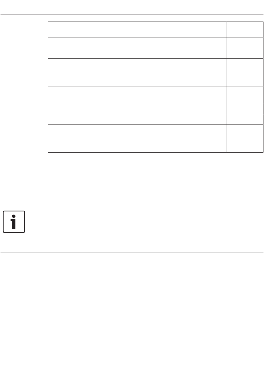
Control Panel Panel Wide Parameters | en 47
Bosch Security Systems, Inc. Program Entry Guide 2017.03 | 03 | F.01U.323.389
Report Category
Route Group 1 Route Group 2 Route Group 3 Route Group 4
User Reports, page 48 Custom Custom Custom Custom
Test Reports, page 49 Yes Yes Yes No
Diagnostic Reports, page
49
Custom Custom Custom Custom
Output Reports, page 50 Yes Yes Yes Custom
Auto Function Reports, page
50
Yes Yes Yes No
RPS Reports, page 50 Custom Custom Custom No
Point Reports, page 50 Yes Yes Yes No
User Change Reports, page
50
Yes Yes Yes No
Access Reports, page 51 Yes Yes Yes Yes
Selections:
Yes - assign all of the reports in this category to the Route Group.
No - assign all of the reports in this category to the Route Group.
Custom - you can not select Custom. Custom shows for a category when at least one of the
reports in the category is configured individually.
Notice!
Configuration for individual reports lost on change from Custom to Yes or No
When Custom appears for a category of reports, it indicates that not all of the reports are set
the same (all Yes or all No). The reports have been set individually.
If you change the reports for a category from Custom to Yes or No, the configuration for the
individual reports in the category is lost. To individually re-assign reports from a report
category to a Route Group, you must click on the report category in the menu tree, Fire
Reports, page 51 for example.
RPS Menu Location
Panel Wide Parameters > Report Routing
Fire Reports
Reports in the Fire category:
– Fire Alarm
– Fire Restoral (After Alarm)
– Fire Missing
– Fire Trouble
– Fire Supervision
– Fire Restoral (After Trouble)
– Fire Cancel
– Fire Supervision Missing
– Fire Supervision Restoral
To individually assign reports from the Fire category to a Route Group, click Fire Reports, page
51 in the menu tree.

48 en | Panel Wide Parameters Control Panel
2017.03 | 03 | F.01U.323.389 Program Entry Guide Bosch Security Systems, Inc.
Notice!
UL 864 Requirement
To comply with UL 864 requirements for Commercial Fire Systems, set the Fire Reports
parameter to Yes for Route Groups 1 and 2.
Gas Reports
Reports in the Gas category:
– Gas Alarm
– Gas Restoral From Alarm
– Gas Missing.
– Gas Trouble
– Gas Supervision
– Gas Restoral From Trouble
– Gas Cancel
– Gas Supervision Missing
– Gas Supervision Restoral
To individually assign reports from the Gas category to a Route Group, click Gas Reports, page
52 in the menu tree.
Burglar Reports
Reports in the Burglar category:
– Alarm Report
– Burg Restore (After Trouble)
– Duress
– Missing Alarm
– User Code Tamper
– Trouble Report
– Missing Trouble
– Non-Fire Supervision
– Point Bus Fail
– Point Bus Restoral
– Non-Fire Cancel
– Alarm Restore
– Supervision Missing
– Unverified Event
To individually assign reports from the Burglar category to a Route Group, click Burglar
Reports, page 52 in the menu tree.
Personal Emergency Reports
Reports in the Personal Emergency category:
– Medical Alarm
– Medical Alarm Restoral (reserved for future use)
– Silent / Hold-Up Alarm
– Silent / Hold-Up Alarm Restoral
– Panic Alarm
– Panic Alarm Restoral (reserved for future use)
To individually assign reports from the Personal Emergency category to a Route Group, click
Personal Emergency Reports, page 53 in the menu tree.
User Reports
Reports in the User category:
– Forced Point: Reports forced point event.

Control Panel Panel Wide Parameters | en 49
Bosch Security Systems, Inc. Program Entry Guide 2017.03 | 03 | F.01U.323.389
– Point Opening: Reports point opening event.
– Point Closing: Reports point closing event.
– Was Force Armed: Reports point forced armed.
– Fail To Open: Reports fail to open event.
– Fail To Close: Reports fail to close event.
– Extend Close Time: Reports extend close time event.
– Opening Report: Reports opening events.
– Forced Close
– Closing Report
– Forced Close Part On Instant
– Forced Close Part On Delay
– Part On Instant
– Part On Delay
To individually assign reports from the User category to a Route Group, click User Reports,
page 53 in the menu tree.
Test Reports
Reports in the Test category:
– Status Report
– Test Report
To individually assign reports from the Test category to a Route Group, click Test Reports, page
54 in the menu tree.
Diagnostic Reports
Reports in the Diagnostic category:
– SDI2 Device Failure
– SDI2 Device Restoral
– Watchdog Reset
– Parameter Checksum Fail
– Reboot
– Phone Line Fail
– Phone Line Restoral
– AC Failure
– AC Restoral
– Battery Missing
– Battery Low
– Battery Restoral
– Route Comm Fail
– Route Comm Restore
– Checksum Fail
– Network Fail
– Network Restoral
– Network Condition
– RF Interference
– RF Interference Restoral
– Equipment Fail
– Equipment Fail Restoral
– Service Smoke Detector
– Service Smoke Detector Restoral
– Personal Notification Communication Trouble
– Personal Notification Communication Trouble Restoral

50 en | Panel Wide Parameters Control Panel
2017.03 | 03 | F.01U.323.389 Program Entry Guide Bosch Security Systems, Inc.
To individually assign reports from the Diagnostic category to a Route Group, click Diagnostic
Reports, page 54 in the menu tree.
Output Reports
Reports in the Output category:
– Sensor Reset
– Output Set
– Output Reset
To individually assign reports from the Output category to a Route Group, click Output
Reports, page 55 in the menu tree.
Auto Function Reports
Reports in the Auto Function category:
– Sked Executed
– Sked Changed
– Fail to Execute
To individually assign reports from the Auto Function category to a Route Group, click Auto
Function Reports, page 56 in the menu tree.
RPS Reports
Reports in the RPS category:
– Event Log Threshold
– Event Log Overflow
– Parameters Changed
– RPS Access OK
– RPS Access Fail
– Remote Reset
– Program Access OK
– Program Access Fail
To individually assign reports from the RPS category to a Route Group, click RPS Reports, page
56 in the menu tree.
Point Reports
Reports in the Point category:
– Service Start
– Service End
– Fire Walk Start
– Fire Walk End
– Walk Test Start
– Walk Test End
– Extra Point
– Send Point Text
– RF Low Battery
– RF Low Battery Restore
– Bypass
– Bypass Restore
To individually assign reports from the Point category to a Route Group, click Point Reports,
page 57 in the menu tree.
User Change Reports
Reports in the User Change category:
– Date Changed
– Time Changed

Control Panel Panel Wide Parameters | en 51
Bosch Security Systems, Inc. Program Entry Guide 2017.03 | 03 | F.01U.323.389
– Delete User
– User Code Change
– Area Watch
– Keyfob Assigned
– Keyfob Removed
– Change Level
To individually assign reports from the User Change category to a Route Group, click User
Change Reports, page 57 in the menu tree.
Access Reports
Reports in the Access category:
– Access Granted
– No Entry
– Door Left Open
– Cycle Door
– Door Unlocked
– Door Secure
– Door Request
– Door Locked
To individually assign reports from the Access category to a Route Group, click Access Reports,
page 58 in the menu tree.
3.9.1 Fire Reports
Default:
Fire Reports
Route Group 1 Route Group 2 Route Group 3 Route Group 4
Fire Alarm Yes Yes Yes Yes
Fire Restoral (after Alarm) Yes Yes Yes No
Fire Missing Yes Yes Yes No
Fire Trouble Yes Yes Yes No
Fire Supervision Yes Yes Yes No
Fire Restoral (after
Trouble)
Yes Yes Yes No
Fire Cancel Yes Yes Yes No
Fire Supervision Missing Yes Yes Yes No
Fire Supervision Restoral Yes Yes Yes No
Selections:
– Yes - assign this report to the Route Group.
– No - do not assign this report to the Route Group.
RPS Menu Location
Panel Wide Parameters > Report Routing > Fire Reports.

52 en | Panel Wide Parameters Control Panel
2017.03 | 03 | F.01U.323.389 Program Entry Guide Bosch Security Systems, Inc.
3.9.2 Gas Reports
Default:
Gas Reports
Route Group 1 Route Group 2 Route Group 3 Route Group 4
Gas Alarm Yes Yes Yes Yes
Gas Restoral from Alarm Yes Yes Yes No
Gas Missing Yes Yes Yes No
Gas Trouble Yes Yes Yes No
Gas Supervision Yes Yes Yes No
Gas Restoral from Trouble Yes Yes Yes No
Gas Cancel Yes Yes Yes No
Gas Supervision Missing Yes Yes Yes No
Gas Supervision Restoral Yes Yes Yes No
Selections:
– Yes - assign this report to the Route Group.
– No - do not assign this report to the Route Group.
RPS Menu Location
Panel Wide Parameters > Report Routing > Gas Reports.
3.9.3 Burglar Reports
Default:
Burglar Reports
Route Group 1 Route Group 2 Route Group 3 Route Group 4
Alarm Report Yes Yes Yes Yes
Burg Restore (after Alarm) Yes Yes Yes No
Duress Yes Yes Yes Yes
Missing Alarm Yes Yes Yes No
User Code Tamper Yes Yes Yes No
Trouble Report Yes Yes Yes No
Missing Trouble Yes Yes Yes No
Non-Fire Supervision Yes Yes Yes No
Point Bus Fail Yes Yes Yes No
Point Bus Restoral Yes Yes Yes No
Non-Fire Cancel Yes Yes Yes No
Alarm Restore Yes Yes Yes No
Supervision Missing Yes Yes Yes No
Unverified Event Yes Yes Yes No

Control Panel Panel Wide Parameters | en 53
Bosch Security Systems, Inc. Program Entry Guide 2017.03 | 03 | F.01U.323.389
Selections:
– Yes - assign this report to the Route Group.
– No - do not assign this report to the Route Group.
RPS Menu Location
Panel Wide Parameters > Report Routing > Burglar Reports.
3.9.4 Personal Emergency Reports
Default:
Personal Emergency Reports Route Group 1 Route Group 2 Route Group 3 Route Group 4
Medical Alarm Yes Yes Yes Yes
Medical Alarm Restoral Yes Yes Yes No
Silent / Hold-Up Alarm Yes Yes Yes Yes
Silent / Hold-Up Alarm
Restoral
Yes Yes Yes No
Panic Alarm Yes Yes Yes Yes
Panic Alarm Restoral Yes Yes Yes No
Selections:
– Yes - assign this report to the Route Group.
– No - do not assign this report to the Route Group.
RPS Menu Location
Panel Wide Parameters > Report Routing > Personal Emergency Reports.
RPS Menu Location
Panel Wide Parameters > Report Routing > Personal Emergency Reports
3.9.5 User Reports
Default:
User Reports
Route Group 1 Route Group 2 Route Group 3 Route Group 4
Forced Point Yes Yes Yes No
Point Opening Yes Yes Yes No
Point Closing Yes Yes Yes No
Was Forced Armed Yes Yes Yes No
Fail to Open Yes Yes Yes No
Fail to Close Yes Yes Yes No
Extent Close Time Yes Yes Yes No
Opening Report No No No No
Forced Close No No No No
Closing Report No No No No
Forced Close Part On
Instant
No No No No

54 en | Panel Wide Parameters Control Panel
2017.03 | 03 | F.01U.323.389 Program Entry Guide Bosch Security Systems, Inc.
User Reports
Route Group 1 Route Group 2 Route Group 3 Route Group 4
Forced Close Part On Delay No No No No
Part On Instant No No No No
Part On Delay No No No No
Send User Text Yes Yes Yes Yes
Selections:
– Yes - assign this report to the Route Group.
– No - do not assign this report to the Route Group.
RPS Menu Location
Panel Wide Parameters > Report Routing > User Reports.
3.9.6 Test Reports
Default:
Test Reports
Route Group 1 Route Group 2 Route Group 3 Route Group 4
Status Report Yes Yes Yes No
Test Report Yes Yes Yes No
Selections:
– Yes - assign this report to the Route Group.
– No - do not assign this report to the Route Group.
RPS Menu Location
Panel Wide Parameters > Report Routing > Test Reports.
3.9.7 Diagnostic Reports
Default:
Diagnostic Reports
Route Group 1 Route Group 2 Route Group 3 Route Group 4
SDI2 Device Failure Yes Yes Yes No
SDI2 Device Restoral Yes Yes Yes No
Watchdog Reset Yes Yes Yes No
Parameter Checksum Fail Yes Yes Yes No
Reboot Yes Yes Yes No
Phone Line Fail Yes Yes Yes No
Phone Line Fail Restoral Yes Yes Yes No
AC Failure Yes Yes Yes No
AC Restoral Yes Yes Yes No
Battery Missing Yes Yes Yes No
Battery Low Yes Yes Yes No

Control Panel Panel Wide Parameters | en 55
Bosch Security Systems, Inc. Program Entry Guide 2017.03 | 03 | F.01U.323.389
Diagnostic Reports
Route Group 1 Route Group 2 Route Group 3 Route Group 4
Battery Restoral Yes Yes Yes No
Route Comm Fail Yes Yes Yes No
Route Comm Restoral Yes Yes Yes No
Checksum Fail Yes Yes Yes No
Network Fail No No No No
Network Restoral No No No No
Network Condition No No No No
RF Interference Yes Yes Yes No
RF Interference Restore Yes Yes Yes No
Equipment Fail Yes Yes Yes No
Equipment Fail Restore Yes Yes Yes No
Service Smoke Detector Yes Yes Yes No
Service Smoke Detector
Restore
Yes Yes Yes No
Personal Notification
Communication Trouble
No No No No
Personal Notification
Communication Trouble
Restore
No No No No
Send Version Text Yes Yes Yes Yes
Selections:
– Yes - assign this report to the Route Group.
– No - do not assign this report to the Route Group.
Notice!
Enable Route Comm Fail and Rout Comm Restore reports in only one route group.
RPS Menu Location
Panel Wide Parameters > Report Routing > Diagnostic Reports.
3.9.8 Output Reports
Default:
Output Reports
Route Group 1 Route Group 2 Route Group 3 Route Group 4
Sensor Reset Yes Yes Yes No
Output Set Yes Yes Yes No
Output Reset Yes Yes Yes No

56 en | Panel Wide Parameters Control Panel
2017.03 | 03 | F.01U.323.389 Program Entry Guide Bosch Security Systems, Inc.
Output Reports
Route Group 1 Route Group 2 Route Group 3 Route Group 4
Send Output Name Text Yes Yes Yes Yes
Selections:
– Yes - assign this report to the Route Group.
– No - do not assign this report to the Route Group.
RPS Menu Location
Panel Wide Parameters > Report Routing > Output Reports.
3.9.9 Auto Function Reports
Default:
Auto Function Reports
Route Group 1 Route Group 2 Route Group 3 Route Group 4
Sked Executed Yes Yes Yes No
Sked Changed Yes Yes Yes No
Fail to Execute Yes Yes Yes No
Selections:
– Yes - assign this report to the Route Group.
– No - do not assign this report to the Route Group.
RPS Menu Location
Panel Wide Parameters > Report Routing > Auto Function Reports.
3.9.10 RPS Reports
Default:
RPS Reports
Route Group 1 Route Group 2 Route Group 3 Route Group 4
Event Log Threshold Yes Yes Yes No
Event Log Overflow Yes Yes Yes No
Parameters Changed Yes Yes Yes No
RPS Access OK Yes Yes Yes No
RPS Access Fail No No No No
Remote Reset Yes Yes Yes No
Program Access OK Yes Yes Yes No
Program Access Fail Yes Yes Yes No
Selections:
– Yes - assign this report to the Route Group.
– No - do not assign this report to the Route Group.
RPS Menu Location
Panel Wide Parameters > Report Routing > RPS Reports.

Control Panel Panel Wide Parameters | en 57
Bosch Security Systems, Inc. Program Entry Guide 2017.03 | 03 | F.01U.323.389
3.9.11 Point Reports
Default:
Point Reports
Route Group 1 Route Group 2 Route Group 3 Route Group 4
Service Start Yes Yes Yes No
Service End Yes Yes Yes No
Fire Walk Start Yes Yes Yes No
Fire Walk End Yes Yes Yes No
Walk Test Start Yes Yes Yes No
Walk Test End Yes Yes Yes No
Extra Point Yes Yes Yes No
Send Point Text Yes Yes Yes No
RF Low Battery Yes Yes Yes No
RF Low Battery Restore Yes Yes Yes No
Bypass Yes Yes Yes No
Bypass Restore Yes Yes Yes No
Selections:
– Yes - assign this report to the Route Group.
– No - do not assign this report to the Route Group.
RPS Menu Location
Panel Wide Parameters > Report Routing > Point Reports.
RPS Menu Location
Panel Wide Parameters > Report Routing > Point Reports
3.9.12 User Change Reports
Default:
User Change Reports
Route Group 1 Route Group 2 Route Group 3 Route Group 4
Date Changed Yes Yes Yes Yes
Time Changed Yes Yes Yes No
Delete User Yes Yes Yes No
User Code Change Yes Yes Yes No
Area Watch Yes Yes Yes No
Keyfob Assigned Yes Yes Yes No
Keyfob Removed Yes Yes Yes No
Change Level Yes Yes Yes Yes
Selections:
– Yes - assign this report to the Route Group.

58 en | Panel Wide Parameters Control Panel
2017.03 | 03 | F.01U.323.389 Program Entry Guide Bosch Security Systems, Inc.
– No - do not assign this report to the Route Group.
RPS Menu Location
Panel Wide Parameters > Report Routing > User Change Reports.
3.9.13 Access Reports
Default:
Access Reports
Route Group 1 Route Group 2 Route Group 3 Route Group 4
Access Granted Yes Yes Yes Yes
No Entry Yes Yes Yes Yes
Door Left Open Yes Yes Yes Yes
Cycle Door Yes Yes Yes Yes
Door Unlocked Yes Yes Yes Yes
Door Secure Yes Yes Yes Yes
Door Request Yes Yes Yes Yes
Door Locked Yes Yes Yes Yes
Selections:
– Yes - assign this report to the Route Group.
– No - do not assign this report to the Route Group.
RPS Menu Location
Panel Wide Parameters > Report Routing > Access Reports.
3.10 Communicator, overview
There are four Route Groups. Reports are assigned to Route Groups by category (Fire Reports
or Burglar Reports for example) or individually (Fire Alarm for example) . Refer to Reporting
Overview, page 44 for information about assigning reports to Route Groups.
Use the parameters under this Communicator heading to assign a Primary Destination Device
and a Backup Destination Device to each Route Group. The Primary Destination Device is the
first used to send reports. If the Primary Destination Device fails to send the report, the
Backup Destination Device destination device is used.
The control panel makes up to ten communication attempts using the primary and backup
destination devices to send reports in a Route Group. The control panel alternates between
the primary and backup destination devices as shown below. If unsuccessful after 10
attempts, it creates a Comm Fail Event.
1. Primary Destination Device
2. Primary Destination Device
3. Backup Destination Device
4. Backup Destination Device
5. Primary Destination Device
6. Backup Destination Device
7. Primary Destination Device
8. Backup Destination Device
9. Primary Destination Device
10. Backup Destination Device

Control Panel Panel Wide Parameters | en 59
Bosch Security Systems, Inc. Program Entry Guide 2017.03 | 03 | F.01U.323.389
When only the Primary Destination Device is programmed, the control panel makes all ten
attempts using that device.
COMM TROUBLE, COMM FAIL events
When the Primary Destination Device fails to connect to the central station receiver after two
attempts, the control panel switches to the Backup Destination Device. The control panel
sends the original report along with a COMM TROUBLE report. If no Backup Destination
Device is configured, no COMM TROUBLE report is sent.
The control panel sends a COMM RESTORE event the next time it successfully sends a report
using the Primary Destination Device.
If the Primary Destination Device is an IP Destination (Onboard IP, Plug-in Cellular IP, SDI2
Address 1, or SDI2 Address 2), the control sends the original event along with a COMM
TROUBLE report that includes an SDI2 number modifier (SDI2##). The SDI2 modifier identifies
the IP Destination Device type. Refer to the table below.
IP Destination Type
SDI2 number
modifier for IP
Destination 1
SDI2 number
modifier for IP
Destination 2
SDI2 number
modifier for IP
Destination 3
SDI2 number
modifier for IP
Destination 4
Onboard Ethernet 10 20 30 40
Plug-in Cellular 18 28 38 48
SDI2 Address 1 11 21 31 41
For example, a COMM TROUBLE report for Route Group 1 with the Primary Destination Device
assigned to Plug-in Cellular, Destination 2 would be: COMM TROUBLERG1 SDI228
The control panel generates COMM TROUBLE events when positive acknowledgement from
the central station receiver to a polls are not received after the configured number of retries.
If all attempts to both the primary destination device and the backup destination device fail, a
COMM FAIL RG# event is generated. COMM RESTORE events are not generated for COMM
FAIL events.
Notice!
CAN/ULC S304 requirement, do not clear pending reports
When CAN/ULC S304 is set to YES, the control panel does not clear pending reports before
creating a COMM FAIL event. It continues to queue reports for the failed route until one of
the failed routes in the route group restores. If the queue reaches the capacity of the panel
event log, the oldest reports are cleared (overwritten).
3.10.1 Primary Destination Device
Default:No Device
Selections:
– No Device
– Onboard IP Destination 1
– Onboard IP Destination 2
– Onboard IP Destination 3
– Onboard IP Destination 4
– (Plug-in) Cellular Destination 1
– (Plug-in) Cellular Destination 2
– (Plug-in) Cellular Destination 3
– (Plug-in) Cellular Destination 4
– (Plug-in) Phone Destination 1

60 en | Panel Wide Parameters Control Panel
2017.03 | 03 | F.01U.323.389 Program Entry Guide Bosch Security Systems, Inc.
– (Plug-in) Phone Destination 2
– (Plug-in) Phone Destination 3
– (Plug-in) Phone Destination 4
– SDI2 address 1 Destination 1
– SDI2 address 1 Destination 2
– SDI2 address 1 Destination 3
– SDI2 address 1 Destination 4
This parameter sets the Primary Destination Device for a Route Group. The control panel uses
the device to send reports to the central station receiver.
The Primary Destination Device selections pair a communicator (onboard IP communicator,
plug-in cellular communicator, plug-in phone communicator, or SDI2 module) and a
destination (Network Address, page 62, or Phone and Phone Parameters, page 29)
RPS Menu Location
Panel Wide Parameters > Communicator > Primary Destination Device
Further information
For more information on how the control panel sends reports, refer to Reporting Overview,
page 44 and Communicator, overview, page 58.
3.10.2 Backup Destination Device
Default:No Device
Selections:
– No Device
– Onboard IP Destination 1
– Onboard IP Destination 2
– Onboard IP Destination 3
– Onboard IP Destination 4
– (Plug-in) Cellular Destination 1
– (Plug-in) Cellular Destination 2
– (Plug-in) Cellular Destination 3
– (Plug-in) Cellular Destination 4
– (Plug-in) Phone Destination 1
– (Plug-in) Phone Destination 2
– (Plug-in) Phone Destination 3
– (Plug-in) Phone Destination 4
– SDI2 address 1 Destination 1
– SDI2 address 1 Destination 2
– SDI2 address 1 Destination 3
– SDI2 address 1 Destination 4
This parameter sets the Backup Destination Device for a Route Group. The control panel uses
the backup device to send reports to the central station receiver when the primary device
fails.
The Backup Destination Device selections pair a communicator (onboard IP communicator,
plug-in cellular communicator, plug-in phone communicator, or SDI2 module) and a
destination (Network Address, page 62, or Phone and Phone Parameters, page 29)
Do not select the same destination device for both Primary Destination Device and Backup
Destination Device for a Route Group.
RPS Menu Location
Panel Wide Parameters > Communicator > Backup Destination Device

Control Panel Panel Wide Parameters | en 61
Bosch Security Systems, Inc. Program Entry Guide 2017.03 | 03 | F.01U.323.389
Further information
For more information on how the control panel sends reports, refer to Reporting Overview,
page 44 and Communicator, overview, page 58.
3.10.3 RG Same Network Receiver
Default: Yes
Selections:
– Yes - the control panel uses the same authentication key to communicate with both the
primary and backup destinations that are the same receiver. Upon detection of a
Communication Trouble on either the primary or backup enhanced communication
destinations, the working destination immediately changes to the faster poll rate.
– No - the control panel uses separate authentication keys to communicate with the
primary and backup receivers. Upon detection of a Communication Trouble on either the
primary or backup enhanced communication destination, the working destination
continues to use its configured poll rate. For example: this would be used when reporting
to a receiver over a LAN / WAN and another is reporting to the same receiver over the
Internet from the cellular service provider. This configuration also typically has the poll
rate set to a slower poll rate than the primary such as every 4 hours.
Use the Route Group Same Network Receiver parameter to ensure that the authentication
keys from the control panel to receiver are the same when the destinations to the receiver use
different IP Addresses or Port Numbers. This parameter also enables the backup destination
poll time to change to the primary poll time in the event of a Communication Trouble event.
Set this parameter to Yes when the following applies:
– Both primary and backup devices use enhanced communication via an IP destination (on-
board or SDI2).
– Both primary and backup destinations are the same receiver with different IP Addresses
that can be accessed from more than one network such as on a LAN / WAN and over the
Internet
– Both primary and backup destinations use different poll rates, although it is not
necessary.
If the poll rate is set to 5 minutes or faster, there is a possibility that data usage might exceed
your cellular data plan. Be sure that any Communication Trouble events are addressed as soon
as possible.
RPS Menu Location
Panel Wide Parameters > Communicator > RG Same Network Receiver
3.10.4 Time Synchronization
Default:
Route Group 1: Yes
Route Groups 2-4: No
Selections: Yes / No
This parameter enables the control panel to synchronize its time and date with the central
station receiver. Time synchronization requires the control panel to be configured to send
reports to the central station receiver over an IP network (Ethernet or cellular) using the
Reporting Format, page 62.
– Time Sync does not work when the Destination Device is set to telephone or the
reporting format is Contact ID.
– Time Sync must be performed over a network connection (Ethernet or cellular).
– Time Sync is applicable to all route groups, but can only be enabled for one route group
at a time

62 en | Panel Wide Parameters Control Panel
2017.03 | 03 | F.01U.323.389 Program Entry Guide Bosch Security Systems, Inc.
Off by 30 Minutes or Less
When the control panel time is off by 30 minutes or less, it adjusts its timekeeping to make up
the difference. If the control panel's time is slow, the control panel counts seconds faster than
once per second. If the control panel's time is fast, the control panel counts seconds slower
than once per second. The modified counting of seconds remains in effect until the control
panel time is in synchronization with the central station receiver time. Since every second
occurs, there are no skips in time. No Skeds scheduled to be run are skipped.
Off by More than 30 Minutes
When the control panel time is off by more than 30 minutes, it checks its date. If the day,
month, or year is different from the central station receiver, the control panel sets its date and
time to the central station receiver date. The control panel then sets its time to the Central
Station receiver time. Due to a forward change in time, scheduled Skeds might not run. Due to
a backward change in time, scheduled Skeds might be repeated.
RPS Menu Location:
Panel Wide Parameters > Communicator > Time Synchronization
3.11 Enhanced Communication
3.11.1 Reporting Format
Default:Modem4
Selections:
– Contact ID - Use this format when the central station receiver only supports contact ID.
– Modem4 - The control panel sends expanded Modem4 Communication Format reports to
the central station receiver.
This parameter sets the central station receiver format for transmission of reports.
When using telephone or network reporting, event reports can be routed to a central station
receiver using either Contact ID or Modem4 format. Contact ID and Modem4 reports identify
points and passcode User ID codes at the receiver. When reporting point events, Modem4 also
sends point text as programmed in Point Assignments.
Notice!
When using Contact ID, you must disable Time Synchronization, page 61
RPS Menu Location:
Panel Wide Parameters > Enhanced Communications > Reporting Format
3.11.2 Network Address
Default: Blank
Selections: IPv4 Address (0.0.0.0 to 255.255.255.255) or Hostname (Up to 255 Characters)
This parameter sets the IP address for Destinations 1-4.
There are four available Destinations to route events to.
If events are going to be routed to an IP Address (in a Private Local or Wide Area Network
application), you need to determine which Destination to use (Destination 1 – Destination 4)
and enter the appropriate IP Address for that Destination.
Whenever the central station requests a change to the Network Address, page 62 or Port
Number, page 63 configured in the control panel, the central station receiver might
resynchronize the control panel's anti-replay/anti-substitution static key.

Control Panel Panel Wide Parameters | en 63
Bosch Security Systems, Inc. Program Entry Guide 2017.03 | 03 | F.01U.323.389
When Port Number/IP Address pairs have duplicate values in a control panel, RPS shows a
warning message and asks if you wish to continue. If you click No, RPS forces you to enter
unique values for the Port Number and IP Address fields. If you click Yes, RPS allows you to
enter duplicate values.
RPS Menu Location
Panel Wide Parameters > Enhanced Communications > Network Address (Destinations 1-4)
3.11.3 Port Number
Default: 7700
Selections: 1 to 65,535
This parameter assigns a unique port number for each destination used to communicate with
the central station over a network.
When upgrading a non-control panel account to a control panel account, RPS forces the
default to 7700.
Whenever the central station requests a change to the Network Address, page 62 or Port
Number, page 63 configured in the control panel, the central station receiver might
resynchronize the control panel's anti-replay/anti-substitution static key.
When Port Number/IP Address pairs have duplicate values in a control panel, RPS shows a
warning message and asks if you wish to continue. If you click No, RPS forces you to enter
unique values for the Port Number and IP Address fields. If you click Yes, RPS allows you to
enter duplicate values.
RPS Menu Location
Panel Wide Parameters > Enhanced Communications > Port Number(Destination1to4)
3.11.4 Receiver Supervision Time
Default: 4 Hours - Medium Security
Selections:
– 200 Seconds - UL1610
– 300 Seconds - NFPA 72 2010
– 1 Hour - NFPA 72 2013
– 4 Hours - Medium Security
– 24 Hours - Daily
– 25 - Hours
– 90 Seconds - High Security
– No Polling
– 95-195, 205-1275 Seconds - selections available in 5 second intervals
– 2, 3, 5-23, 26-255 Hours
– Custom
With the exception of the Custom selection, the Receiver Supervision Time selection
automatically sets the Poll Rate (sec.), page 64, ACK Wait Time (sec.), page 66, and Retry
Count, page 66 parameters. These parameters can only be edited when the Receiver
Supervision Time parameter is set to Custom.
The first time Custom is selected, the default value for the Poll Rate, ACK Wait and Retry
Count parameters is zero. Once these parameters are changed from the default, RPS retains
the values even if the Receiver Supervision Time parameter is changed from the Custom
selection. Each time Custom is reselected the Poll Rate, ACK Wait and Retry Count parameters
are set to the saved values.

64 en | Panel Wide Parameters Control Panel
2017.03 | 03 | F.01U.323.389 Program Entry Guide Bosch Security Systems, Inc.
Important Cellular Service Information
To avoid monthly overages, Bosch offers service plans that align with the common
applications for cellular connectivity on alarm panels.
WARNING: This parameter is critical for optimized communication.
Refer to Configuring for Cellular Service, page 252 for important information regarding how to
set up your control panel to ensure proper cellular communication with the central station
receiver.
RPS Menu Location
Panel Wide Parameters > Enhanced Communication > Receiver Supervision Time
3.11.5 Poll Rate (sec.)
Default: 0 (Receiver Supervision Time parameter set to Custom)
Selections: (in seconds)
– 0 - disables the ‘heartbeat’ poll.
– 5 to 65534 - enables the poll rate for the amount of time programmed here (in seconds).
– 65535 - the 'heartbeat' poll occurs once a day.
Notice!
Receiver Supervision Time, page 63 parameter must be set to Custom
to edit Poll Rate (sec.), page 64, ACK Wait Time (sec.), page 66 and Retry Count, page 66
parameters
With the exception of the Custom selection, the Receiver Supervision Time parameter
automatically sets the Poll Rate, ACK Wait Time, and Retry Count parameters. These
parameters can only be edited when the Receiver Supervision Time parameter is set to
Custom.
The first time Custom is selected, the default value for the Poll Rate, ACK Wait and Retry
Count parameters is zero. Once these parameters are changed from the default, RPS retains
the values even if the Receiver Supervision Time parameter is changed from the Custom
selection. Each time Custom is reselected the Poll Rate, ACK Wait and Retry Count
parameters are reset to the saved values.
When the Receiver Supervision Time is set to Custom, use this parameter to set the interval
(in seconds) in which each SDI2 destination sends a heartbeat poll to the central station
receiver for supervision purposes. This ensures the integrity of the connection at all times.
The value entered in ACK Wait Time (Destinations 1 to 4) is the length of time the control
panel waits for an acknowledgment of a heartbeat poll. If the acknowledgment is not received,
the control panel checks to determine if the destination's retry count entry is greater than
zero. If so, the control panel retries the number of times entered in Retry Count (Destinations
1 to 4) to send the heartbeat poll before declaring the path failed and generating a COMM
FAIL SDI2 ## event. (Refer to the table below for the correct ## value.)
Device Destination 1 Destination 2 Destination 3 Destination 4
SDI2-1 11 21 31 41
Onboard
Ethernet
10 20 30 40
Onboard Cellular 18 28 38 48

Control Panel Panel Wide Parameters | en 65
Bosch Security Systems, Inc. Program Entry Guide 2017.03 | 03 | F.01U.323.389
Poll Rate (Destinations 1 to 4), ACK Wait Time (Destinations 1 to 4), and Retry Count
(Destinations 1 to 4) determine how the network destination is supervised between the
communication device and the central station receiver(s). Do not confuse the SDI2 destination
supervision with the supervision of the SDI2 device itself (the connection of the SDI2 device
to the control panel).
If this parameter is programmed with a value and the central station does not acknowledge
the poll from the control panel, keypads sound a trouble event. To send this event to the
central station, refer to Comm Fail for more information.
Heartbeat Example:
– Poll Rate (Destinations 1 to 4) = 120 seconds
– ACK Wait Time (Destinations 1 to 4) = 10 seconds
– Retry Count (Destinations 1 to 4) = 2
When the control panel first powers up, the first heartbeat poll for Destination 1 is sent and
acknowledged in 1 second. 120 seconds after the first heartbeat poll is sent, the second
heartbeat poll for Destination 1 is sent to the central station receiver.
Retry Count Example:
An acknowledgement of the heartbeat was not received within 10 seconds. The control panel
sends the next heartbeat poll after the first 10-second ACK wait period expires. If the central
station does not acknowledge this heartbeat poll, the control panel continues to resend. When
the resend count is reached, the control panel declares this path as failed and generates the
Comm Fail ## event. The control panel continues to re-send the heartbeat poll every 10
seconds until it receives an acknowledgement, even after declaring a Comm Fail.
When the control panel receives acknowledgement from the central station, the control panel
returns to the normal poll rate.
If more than one network destination is used, the control panel handles them on a successive
basis. For example, if acknowledgement from SDI Destination 1 is not received within 10
seconds (based on the above example), the control panel moves to SDI Destination 2 to send
its heartbeat poll, and subsequently waits for the ACK before returning to SDI Destination 1 to
resend the heartbeat poll.
Entries are made in 1-second increments.
– 5 minutes = 300 seconds
– 1 hour = 3600 seconds
– 12 hours = 43,200 seconds
– 18 hours = 64,800 seconds
If heartbeat polls are enabled to send by an SDI Destination, and ACK Wait Time
(Destinations1 to 4) is exceeded, a COMM FAIL ## event occurs. When this event occurs, all
events routed to this destination go immediately to the backup destination.
Notice!
When sending reports to a central station receiver over a network destination, set this
parameter to a non-zero value. Failure to program a value into this parameter could prevent a
failed network communication destination from restoring to normal.
If the control panel is programmed to send a heartbeat poll to the central station, a rate of 75
seconds maintains the virtual link in most network configurations. Decreasing the value for
this parameter increases the amount of idle communication between the SDI2 device and the
central station receiver. Increased idle communication between the control panel and receiver
decreases the control panel's event reporting efficiency.

66 en | Panel Wide Parameters Control Panel
2017.03 | 03 | F.01U.323.389 Program Entry Guide Bosch Security Systems, Inc.
The control panel readjusts the heartbeat poll rate temporarily from less than 300 seconds to
300 seconds when online with RPS. The poll rate returns to the programmed value after the
RPS session ends.
RPS Menu Location
Panel Wide Parameters > Enhanced Communications > Poll Rate
3.11.6 ACK Wait Time (sec.)
Default: 0 (Receiver Supervision Time parameter set to Custom)
Selections: 5 to 65535 (seconds)
Notice!
Receiver Supervision Time, page 63 parameter must be set to Custom
to edit Poll Rate (sec.), page 64, ACK Wait Time (sec.), page 66 and Retry Count, page 66
parameters
With the exception of the Custom selection, the Receiver Supervision Time parameter
automatically sets the Poll Rate, ACK Wait Time, and Retry Count parameters. These
parameters can only be edited when the Receiver Supervision Time parameter is set to
Custom.
The first time Custom is selected, the default value for the Poll Rate, ACK Wait and Retry
Count parameters is zero. Once these parameters are changed from the default, RPS retains
the values even if the Receiver Supervision Time parameter is changed from the Custom
selection. Each time Custom is reselected the Poll Rate, ACK Wait and Retry Count
parameters are reset to the saved values.
This parameter determines how long the control panel will wait for an acknowledgement from
the central station after a heartbeat poll or an actual event has been transmitted. Actual (non-
heartbeat) events will wait the set value or a maximum of 15 seconds before the next
communication attempt is made.
RPS Menu Location
Panel Wide Parameters > Enhanced Communications > ACK Wait Time
3.11.7 Retry Count
Default: 0 (Receiver Supervision Time parameter set to Custom)
Selections:
0 - continuous retries. Path failure events are not generated.
1 to 255 - path failure events are generated after the number of retries are reached.
Notice!
Receiver Supervision Time, page 63 parameter must be set to Custom
to edit Poll Rate (sec.), page 64, ACK Wait Time (sec.), page 66 and Retry Count, page 66
parameters
With the exception of the Custom selection, the Receiver Supervision Time parameter
automatically sets the Poll Rate, ACK Wait Time, and Retry Count parameters. These
parameters can only be edited when the Receiver Supervision Time parameter is set to
Custom.
The first time Custom is selected, the default value for the Poll Rate, ACK Wait and Retry
Count parameters is zero. Once these parameters are changed from the default, RPS retains
the values even if the Receiver Supervision Time parameter is changed from the Custom
selection. Each time Custom is reselected the Poll Rate, ACK Wait and Retry Count
parameters are reset to the saved values.

Control Panel Panel Wide Parameters | en 67
Bosch Security Systems, Inc. Program Entry Guide 2017.03 | 03 | F.01U.323.389
This parameter determines how many times the control panel will re-send the heartbeat event
before declaring a Path Failure for a given SDI2 Destination.
An event is defined by the following device and destination combinations.
Device Destination 1 Destination 2 Destination 3 Destination 4
SDI2-1 11 21 31 41
Onboard
Ethernet
10 20 30 40
Onboard Cellular 18 28 38 48
RPS Menu Location
Panel Wide Parameters > Enhanced Communications > Retry Count
3.11.8 AES Key Size
Default: No Encryption
Selections:
– No Encryption
– 128 bit key length is 16 bytes.
– 192 bit key length is 24 bytes.
– 256 bit key length is 32 bytes.
This parameter identifies the AES key size.
RPS Menu Location:
Panel Wide Parameters > Enhanced Communications > AES Key Size
3.11.9 AES Encryption Key
Default: <Default> (not encrypted)
Selections: Thirty-two hexadecimal characters represented by an ID (01 to 100).
This parameter allows each receiver destination to be configured with a unique AES
encryption key.
The AES Encryption Key is based on AES Key Size, page 67. For the encryption key
configuration, only Key ID & Name is displayed.
By default RPS sets the AES Key string to <Default>. RPS validates if two or more network
destinations have the same network address. If yes, then RPS notifies the user to use the
same encryption key for those network destinations.
AES key strings are configuredin Config >> System >> Encryption Key Tab
RPS Menu Location
Panel Wide Parameters > Enhanced Communications > AES Encryption Key
3.12 SDI2 RPS / Enhanced Communication
3.12.1 Enable Enhanced Communication?
Default: Yes
Selections:
– Yes - enables reporting using an IP communicator (onboard, plug-in cellular, or SDI2).
– No - disables reporting using an IP communicator.
To enable reporting using an IP communicator (onboard, plug-in cellular, or SDI2), set this
parameter to Yes, and set the Primary Destination Device, page 59 or Backup Destination Device,
page 60 for at least one RouteGroup to an Onboard IP, Plug-in Cellular, or SDI2 device.

68 en | Panel Wide Parameters Control Panel
2017.03 | 03 | F.01U.323.389 Program Entry Guide Bosch Security Systems, Inc.
3.12.2 Answer RPS Over Network?
Default: Yes
Selections:
– Yes - enables automatic RPS initiated connections over the network.
– No - prevents automatic RPS initiated connections over the network.
This parameter determines if the control panel automatically accepts RPS initiated
connections through the onboard Ethernet communicator or a network interface module on
the SDI2 bus.
If this parameter is set no, RPS initiated connections can be accepted at a keypad by selecting
Answer from the RPS menu (Actions > RPS > Answer).
Notice!
Service Mode allows RPS connections over network
When the control panel is in service mode, the control panel automatically accepts RPS
initiated connections over the network, even if this parameter is set to No.
To place the control panel in installer mode, press and hold the control panel RESET button
until the Heartbeat LED flashes fast. Keypads show SERVICE MODE and prompt for the
installer passcode. Enter the installer passcode and press [ENTER].
RPS Menu Location
Panel Wide Parameters > SDI RPS/Enhanced Communication > Answer RPS Over Network
3.12.3 RPS Address Verification
Default: No
Selections:
– Yes - this setting verifies that the incoming RPS IP address matches the address entered
in RPS Network Address, page 68.
– No this setting allows RPS to connect to the control panel from any IP address. No
verification is performed.
When enabled, this parameter verifies that RPS connects to the control panel from a known IP
address.
This verification can be temporarily disabled by selecting ALLOW ANSWER in the MENU 34
menu.
RPS Menu Location
Panel Wide Parameters > SDI RPS/Enhanced Communication > RPS Address Verification
3.12.4 RPS Network Address
Default: Blank
Selections: IPv4 address or Hostname
This parameter sets the IP address or hostname for RPS.
Be sure to contact your network administrator to find out which IP Address or hostname your
RPS computer is connected to.
RPS Menu Location
Panel Wide Parameters > SDI RPS/Enhanced Communication > RPS Network Address
3.12.5 RPS Port Number
Default:7750
Selections:1 – 65535
This parameter is used as the destination UDP port for control panel-initiated RPS network
sessions.

Control Panel Panel Wide Parameters | en 69
Bosch Security Systems, Inc. Program Entry Guide 2017.03 | 03 | F.01U.323.389
RPS Menu Location
Panel Wide Parameters > SDI RPS/Enhanced Communication > RPS Port Number
3.13 Power Supervision
3.13.1 AC Fail Time
Default:01:00
Selections:00:01 to 90:00 (Minutes:Seconds)
This parameter sets the amount of time that the AC power must be off before the control
panel sends an AC Failure report.
RPS Menu Location
Panel Wide Parameters > Power Supervision > AC Fail Time
3.13.2 Resend AC Fail
Default: No Reports
Selections:
– No Report -do not re-send AC Fail report.
– After 6 Hours - e-send AC Fail report to central station after 6 hours of non-restoral.
– After 12 Hours - re-send AC Fail report to central station after 12 hours of non-restoral.
This parameter sets the time interval that must pass without the AC failure event being
restored before the control panel re-sends the AC Failure report to the central station.
RPS Menu Location
Panel Wide Parameters > Power Supervision > Resend AC Fail
3.13.3 AC Fail Display
Default: 60
Selections: 10 to 300 (seconds) (increments of 5)
This parameter sets the amount of time in seconds the system waits before sounding a local
AC Failure annunciation.
RPS Menu Location
Panel Wide Parameters > Power Supervision > AC Fail Display
3.13.4 AC Fail / Restoral Report
Default:No
Selections:
– Yes - end AC Fail and AC Restoral reports.
– No - do not send AC Fail and AC Restoral reports.
This parameter sends AC Power Supervision reports to the central station at the time
programmed for AC Fail Time.
RPS Menu Location
Panel Wide Parameters > Power Supervision > AC Fail/Restoral Report
3.13.5 AC Tag Along
Default:Yes
Selections:
– Yes - send AC messages as tag along events.
– No - do not send AC messages as tag along events.
This parameter sends AC reports only if any other event occurs while AC is off-normal.
RPS Menu Location
Panel Wide Parameters > Power Supervision > AC Tag Along.

70 en | Panel Wide Parameters Control Panel
2017.03 | 03 | F.01U.323.389 Program Entry Guide Bosch Security Systems, Inc.
3.13.6 AC / Battery Buzz
Default:No
Selections:
– Yes - initiate panel-wide trouble tone at all keypads.
– No - do not Initiate panel-wide trouble tone at keypads.
This parameter initiates a panel-wide trouble tone at keypads when the AC fails or the battery
is low or missing.
This parameter does not prevent AC fail or low battery displays at the keypad.
RPS Menu Location
Panel Wide Parameters > Power Supervision > AC/Battery Buzz
3.13.7 Battery Fail / Restoral Report
Default:Yes
Selections:
– Yes - battery failure and restoral reports are sent to the central station. They are routed to
the telephone number programmed for Power/Phone events.
– No - battery failure and restoral reports are NOT sent to the central station. This
parameter determines if a report is sent if the battery is low or missing.
The battery must be discharged below 12.1 VDC for 16 seconds before the control panel
responds to a low battery. It takes between 10 and 60 seconds for a missing battery to be
detected.
Modem reports: Missing or shortedBATTERY MISSING; discharged below 12.1 VDCBATTERY
LOW
Contact ID reports: Missing or shorted BATTERY MISSING/DEAD; discharged below 12.1 VDC
LOW SYSTEM BATTERY
RPS Menu Location
Panel Wide Parameters > Power Supervision > Battery Fail/Restoral Report.
3.14 RPS Parameters
3.14.1 RPS Passcode
Default:999999
Selections:6 - 24 alphanumeric characters in length
This parameter verifies that the RPS operator has valid access to connect to the control panel.
Enter a minimum of six characters. Do not use spaces in the passcode. Passcode is case-
sensitive.
The control panel provides an RPS passcode configuration option. This option accepts up to
24 characters, but will allow shorter passcodes. When RPS connects to the control panel, the
correct passcode must be supplied before the control panel will allow RPS to access any
configuration data or control functions.
The RPS passcode defaults to "999999" in the control panel. In an RPS default account, the
passcode is also "999999". A default RPS account can connect to a default control panel
without modifying the RPS passcode in either the RPS account or in the control panel.
RPS Menu Location
Panel Wide Parameters > RPS Parameters > RPS Passcode
3.14.2 Log % Full
Default:0
Selections:0 to 99

Control Panel Panel Wide Parameters | en 71
Bosch Security Systems, Inc. Program Entry Guide 2017.03 | 03 | F.01U.323.389
0 (zero)- This setting disables the LOG THRESHOLD and LOG OVERFLOW events. These
events are not put in the log nor reported to the central station receiver. The control panel
continues to log events after the LOG THRESHOLD report is sent. When it reaches 100%
capacity (memory logger is full and previously stored events will be overwritten), the control
panel generates a local LOG OVERFLOW event.
This parameter determines how full the memory log should be before initiating a call to RPS at
the central station. This allows the central station to call the control panel and copy the
memory log before messages could be overwritten.
The control panel does not call RPS again until it downloads the log and the Log % Full
percentage is again reached. These events are also sent to the control panel's event log.
RPS Menu Location
Panel Wide Parameters > RPS Parameters > Log % Full.
3.14.3 Contact RPS if Log % Full
Default: No
Selections:
Yes - the control panel automatically contacts RPS when the “Log % Full” threshold is
reached.
No - the control panel does not automatically contact RPS when the “Log % Full” threshold is
reached.
RPS Menu Location
Panel Wide Parameters > RPS Parameters > Contact RPS if Log % Full.
3.14.4 RPS Call Back
Default:No
Selections:
– Yes - when the control panel hears the proper RPS passcode, it hangs up the phone,
seizes the phone line, then dials the programmed RPS phone number Refer to RPS Phone
#, page 73. This ensures that only the control panel communicates with the RPS PC
connected to the dialed phone number.
– No - the RPS session is initiated immediately; no call back is required. The control panel
engages in RPS sessions when called from any phone number and a proper RPS passcode
is identified.
Notice!
When using the RPS Callback function, enter a "C" as the last digit in the RPS phone number
if DTMF dialing is used.
This parameter allows the control panel, after it has verified the RPS passcode, to provide an
additional level of security by hanging up and dialing the RPS phone number to call RPS at the
central station prior to allowing any upload or download.
RPS Menu Location
Panel Wide Parameters > RPS Parameters > RPS Call Back
3.14.5 RPS Line Monitor
Default:Yes
Selections:
– Yes - this setting allows the control panel to communicate with RPS after the answering
machine has answered the phone.
72 en | Panel Wide Parameters Control Panel
2017.03 | 03 | F.01U.323.389 Program Entry Guide Bosch Security Systems, Inc.
– No - use this setting if the control panel is not sharing the phone line with an answering
machine.
This parameter enables a control panel that shares a phone line with an answering machine to
communicate with RPS at the central station even though the answering machine has
answered the phone. You must set Answer Armed, page 72 and/or Answer Disarmed, page
72, and the control panel must be in the proper armed state.
Notice!
If RPS Call Back, page 71 is set to Yes, the control panel hangs up the phone after the RPS
tone and a proper RPS passcode is identified, then it calls the RPS phone number.
Notice!
Set this parameter to No if it causes false seizures of the phone line, or if you are not using
RPS. This would indicate that a device using the same frequency tone is also using the phone
line to which the control panel is connected.
RPS Menu Location
Panel Wide Parameters > RPS Parameters > RPS Line Monitor
3.14.6 Answer Armed
Default: 7
Selections: 0 to 15 (rings)
– 0 (zero) This setting disables answering the phone.
– 1 to 15 Use this setting to have the control panel answer the phone after the specified
number of rings when all areas are All On
Notice!
RPS considers Part On as a disarmed state.
This parameter sets the telephone ring counter to answer when all areas are All On. If any area
in the control panel is Part On or disarmed, the Answer Disarmed, page 72 ring counter is
used.
Notice!
PSTN requirement for Australia / New Zealand, disable RPS answer armed/disarmed
If you set the PanelWideParameters > PhoneParameters > PSTN Compatibility parameter to
Australia or New Zealand, you must set this AnswerArmed and the AnswerDisarmed
parameter to 0 (disabled).
RPS Menu Location
Panel Wide Parameters > RPS Parameters > Answer Armed
3.14.7 Answer Disarmed
Default: 7
Selections: 0 to 15 (rings)
– 0 (zero) - this setting disables answering the phone.
– 1 to 15 - use this setting to have the control panel answer the phone after the specified
number of rings when all areas are All On.

Control Panel Panel Wide Parameters | en 73
Bosch Security Systems, Inc. Program Entry Guide 2017.03 | 03 | F.01U.323.389
Notice!
RPS considers Part On as a disarmed state.
This parameter sets the telephone ring counter to answer when any area is in a Part On or
disarmed state.
Notice!
PSTN requirement for Australia / New Zealand, disable RPS answer armed/disarmed
If you set the PanelWideParameters > PhoneParameters > PSTN Compatibility parameter to
Australia or New Zealand, you must set the AnswerArmed and this AnswerDisarmed
parameter to 0 (disabled).
RPS Menu Location
Panel Wide Parameters > RPS Parameters > Answer Disarmed.
3.14.8 RPS Phone #
Default:Blank
Selections:Up to 24 characters
This parameter specifies the phone number the control panel dials to contact RPS.
The control panel dials the programmed number using RPS Phone # as a result of the
following events:
–Log % Full, page 70 threshold is achieved (if enabled).
– The control panel is contacted by RPS and RPS Call Back, page 71 is programmed Yes.
– User selects MENU > Actions > RPS > Call Via Phone (only one attempt is made).
If this parameter is left empty (blank), the control panel does not dial a phone number for
RPS. Refer to Phone Destination 1 (to 4), page 29 when programming this parameter.
RPS Menu Location
Panel Wide Parameters > RPS Parameters > RPS Phone
3.14.9 RPS Modem Speed
Default: 1200
Selections:
– 300
– 1200
– 2400
This parameter sets the baud rate for RPS-to-control panel-communication when using a PSTN
connection.
RPS Menu Location
Panel Wide Parameters > RPS Parameters > RPS Modem Speed.
3.15 Miscellaneous
3.15.1 Duress Type
Default:0
Selections:
– 0 - disabled.
– 1 - increase the last digit by 1 to generate an alarm. For example:
– If the passcode is 6123, 6124 activates a duress alarm.
74 en | Panel Wide Parameters Control Panel
2017.03 | 03 | F.01U.323.389 Program Entry Guide Bosch Security Systems, Inc.
– If the last digit of the passcode is 0, a duress alarm occurs when the user enters 1 as
the last digit of the passcode.
– If the last digit of the passcode is 9, a duress alarm occurs when the user enters 0 as
the last digit of the passcode.
– 2 -increase the last digit by 2 to generate an alarm. For example:
– If the last digit of the passcode is 8, a duress alarm occurs when the user enters 0 as
the last digit of the passcode.
– If the last digit of the passcode is 9, a duress alarm occurs when the user enters 1 as
the last digit of the passcode.
– 3 -send a Duress event when any user passcode entered with Send Duress, page 165 set
to Yes.
This parameter determines whether users add one (+1) or two (+2) to the last digit of the
passcode. To activate a duress alarm, the user increases the value of the last digit of their
passcode when entering it at the keypad.
Notice!
SIA CP-01 False Alarm Reduction requirement
To comply with SIA CP-01 False Alarm Reduction, set this parameter to 3. Refer to SIA CP-01
Verification for more information
Duress is enabled or disabled by area in Area Parameters, Duress Enable, page 93.
The duress alarm is activated when a user enters the duress combination followed by the
termination keys (ESC or ENT).
RPS Menu Location
Panel Wide Parameters > Miscellaneous > Duress Type.
3.15.2 Cancel Reports
Default:Yes
Selections:
– Yes - send Cancel, Fire Cancel and Gas Cancel reports according to Routing.
– No - do not send Cancel, Fire Cancel and Gas Cancel reports.
Use this parameter to determine whether or not Cancel, Fire Cancel and Gas Cancel reports
are sent.
Notice!
SIA CP-01 False Alarm Reduction requirement
To comply with SIA CP-01 False Alarm Reduction, set this parameter to Yes. Refer to SIA
CP-01 Verification for more information.
A Cancel, Fire Cancel and Gas Cancel report is created when a passcode is entered to silence
an Alarm Bell, Gas Bell or a Fire Bell before the bell time expires.
RPS Menu Location
Panel Wide Parameters > Miscellaneous > Cancel Reports
3.15.3 Call for Service Text - First Language
Default: Contact your dealer
Selections: Enter up to 32 characters.
This parameter allows the user to customize the Call for Service message that is displayed at
keypads.
Enter up to 32 characters of text, numbers and symbols.

Control Panel Panel Wide Parameters | en 75
Bosch Security Systems, Inc. Program Entry Guide 2017.03 | 03 | F.01U.323.389
Keypads display the first 20 characters. If more than 20 characters are used, the text scrolls
across the display one time. To scroll the text again, press [ESC].
Spaces before, after and within a string of text are treated as text and are included in the 32
character limit.
Note: First and Second languages are programmed during panel account setup in the Panel
Data window. Supported languages include English, Spanish, French and Portuguese. To view
the languages selected during account set-up, refer to Panel Wide Parameters > Personal
Notification > User Language.
RPS Menu Location
Panel Wide Parameters > Miscellaneous > Call for Service Text - English
3.15.4 Call for Service Text - Second Language
Default: Blank
Selections: Enter up to 32 characters.
This parameter allows the user to customize the Call for Service message that is displayed at
keypads.
Enter up to 32 characters of text, numbers and symbols.
Keypads display the first 20 characters. If more than 20 characters are used, the text scrolls
across the display one time. To scroll the text again, press [ESC].
Spaces before, after and within a string of text are treated as text and are included in the 32
character limit.
Note: First and Second languages are programmed during panel account setup in the Panel
Data window. Supported languages include English, Spanish, French and Portuguese. To view
the languages selected during account set-up, refer to Panel Wide Parameters > Personal
Notification > User Language.
RPS Menu Location
Panel Wide Parameters > Miscellaneous > Call for Service Text- Second Language
3.15.5 On Site Authorization for Firmware Update
Default: No
Selections:
– Yes - require on-site authorization.
– No - on-site authorization is not required.
This parameter requires authorized on-site personnel to enter the authorization code at one of
the keypads at the designated time during the remote firmware update process.
Notice!
Set this parameter to "Yes" for UL listed systems.
If authorization is required, you can modify the authority level required for the authorized user.
NOTE: It is recommend that a full system test be performed whenever firmware is updated
locally or remotely.
Remote firmware updates through Remote Programming Software (RPS) using the RPS
Firmware Update Wizard through the IP connection (on-board ethernet connection or a B42x
module), provides for easy feature enhancements without replacing ROM chips.
Remote firmware updates must be authorized on-site for UL listed systems.
RPS Menu Location
Panel Wide Parameters > Miscellaneous > On-Site Authorization for Firmware Update.

76 en | Panel Wide Parameters Control Panel
2017.03 | 03 | F.01U.323.389 Program Entry Guide Bosch Security Systems, Inc.
Further information
Firmware Update, page 169
3.15.6 Enclosure Tamper Enable
Default: No
Selections:
– Yes - this setting enables the tamper input to generate a system trouble.
– No - no tamper events will be generated from the tamper input.
This parameter monitors the enclosure and processes an enclosure tamper event when the
enclosure is opened.
Note: This function can only be set from RPS.
If the option is changed from Yes to No, an existing enclosure tamper event is cleared, but its
restoral is not logged or reported.
If the option is changed from No to Yes, the tamper input is not processed until after the
control panel detects that the tamper input is normal.
Tamper or tamper restoral is recognized if the event lasts for at least 250 milliseconds. When
the control panel is powered up, or is re-starting for any reason, the tamper input is ignored
until the control panel sees the tamper input become normal. (The installer closes the
enclosure.) Once normal (closed), opening the enclosure might cause an enclosure tamper
trouble.
When an enclosure tamper event is processed, it is indicated on the keypads' displays and the
keypads sound a trouble tone. When the enclosure tamper has been restored, the control
panel automatically removes the tampered enclosure message from the keypads' displays and
the trouble tone is silenced if no other trouble events exist. While an enclosure tamper is
displayed at the keypad, the tamper event does not affect the arming or disarming process.
If installed and enabled, detects control panel door has been opened.
RPS Menu Location
Panel Wide Parameters > Miscellaneous > Enclosure Tamper Enable
3.15.7 Fire Summary Sustain
Default: Yes
Selections:
– Yes - forces the Summary Fire and Summary Gas output to remain on after the Alarm
Silence command.
– No - allows Summary Fire and Summary Gas output to activate when a corresponding
point in the system goes into alarm. This output provides a steady output until all
silenced fire or gas points in the system are returned to normal.
This parameter provides a continuous alarm output to keep fire or gas strobes active after the
fire or gas bell has stopped sounding.
RPS Menu Location
Panel Wide Parameters > Miscellaneous > Fire Summary Sustain
3.15.8 Fire Supervision Event Type
Default:2 (Fire Supervision Restoral)
Selections:
– 0 (Fire Trouble Restoral) - the control panel transmits a FIRE TROUBLE RESTORE when a
Fire Supervision point restores to normal.
– 1 (Fire Alarm Restoral) - the control panel transmits a FIRE ALARM RESTORE when a Fire
Supervision point restores to normal.

Control Panel Panel Wide Parameters | en 77
Bosch Security Systems, Inc. Program Entry Guide 2017.03 | 03 | F.01U.323.389
– 2 (Fire Supervision Restoral) - the control panel transmits a FIRE SUPERVISION RESTORE
when a Fire Supervision point restores to normal.
This parameter determines how the control panel transmits a Fire Supervision Restoral event.
RPS Menu Location
Panel Wide Parameters > Miscellaneous > Fire Supervision Event Type
3.15.9 Fire Trouble Resound
Default:No Fire Trouble Resound
Selections:
– No Fire Trouble Resound - keypads will not re-sound the trouble tone.
– Fire Trouble Resound @ 12:00 PM - keypads will re-sound the trouble tone at 12:00 P.M.
(noon) if any fire or gas point that falls within the scope of a keypad is in an off-normal
state.
– Fire Trouble Resound @ 12:00 AM - keypads will re-sound the trouble tone at 12:00 A.M.
(midnight) if any fire or gas point that falls within the scope of a keypad is in an off-
normal state.
This parameter determines if a fire or gas trouble event, although previously acknowledged
and silenced at a keypad, will automatically resound the trouble tone at 12:00 P.M., 12:00
A.M., or not at all if the point is still in an off-normal state.
A user's passcode must have an authority level of 1 or greater in an area to silence troubles.
RPS Menu Location
Panel Wide Parameters > Miscellaneous > Fire Trouble Resound
3.15.10 Early Ambush Time
Default: 10
Selections: 5 to 30 (minutes) (1-minute increments)
Use this parameter to enter the amount of time allowed for the user to enter a second
passcode at the keypad when the Area parameter, Early Ambush?, page 97 is set to Yes.
If a second passcode is not entered before the Early Ambush Time ends, a Duress event is
generated based on the first user passcode.
RPS Menu Location
Panel Wide Parameters > Miscellaneous > Early Ambush Time
3.15.11 Second Ambush Code
Default: Unique
Selections:
– Unique - the passcode used to end the Early Ambush Time, page 77 must be different
from the passcode used to disarm the area.
– Any - the Early Ambush Time can be stopped using a different passcode, or the same
passcode used to disarm the area.
This parameter determines whether the same passcode can be used to start and end the Early
Ambush?, page 97 process.
RPS Menu Location
Panel Wide Parameters > Miscellaneous > Second Ambush Code
3.15.12 Abort Window
Default: 30 sec
Selections: 15 to 45 (seconds) (1-sec increments)
78 en | Panel Wide Parameters Control Panel
2017.03 | 03 | F.01U.323.389 Program Entry Guide Bosch Security Systems, Inc.
Use this parameter to enter the number of seconds the control panel delays sending an alarm
event to the central station from a point assigned to a Point Index with the Alarm Abort, page
194 feature enabled.
Notice!
To meet UL requirements, the combined Entry Delay, page 185 and Abort Window time must
not exceed 60 sec.
Notice!
For SIA CP-01 Compliance, Abort Window is a required parameter.
If an alarm silence operation is performed before this time elapses, the alarm transmission is
aborted and the keypad shows an optional message (Refer to Abort Display, page 115).
When an abort alarm timer starts, it does not stop until an alarm silence operation is
performed, or the time expires. This feature does not apply to fire alarms or invisible point
alarms.
RPS Menu Location
Panel Wide Parameters > Miscellaneous > Abort Window
3.15.13 Passcode Length
Default: Disabled
Selections:
– Disabled
– 3, 4, 5, or 6 digits
Select the number of digits allowed in all passcodes.
Notice!
To comply with SIA CP-01 False Alarm Reduction, set this parameter between 3 and 6 digits.
Refer to SIA CP-01 Verification for more information.
If the passcode length is changed and duplicate or unusable passcodes are created as a result,
a WARNING! Duplicate / Unusable Passcodes Present window opens.
Passcodes identified as a duplicate appear in bold red.
Passcodes identified as unusable (length is under or over the value entered in this parameter),
appear in bold blue.
To change a passcode:
1. Click the appropriate cell in the User Passcode column to select the passcode.
2. Press the [Backspace] key on your keyboard to clear the cell.
3. Enter the new passcode.
There are two option buttons that control how this parameter handles passcode entries:
– Save corrected passcodes: This option is selected by default. All passcodes marked as
duplicate or unusable must be fixed before you click OK to save the passcode
corrections.
– Disable passcode length and store the data in this account: This option disables the
Passcode Length parameter and allows you to save passcodes of varying lengths in the
RPS account.
Control Panel Panel Wide Parameters | en 79
Bosch Security Systems, Inc. Program Entry Guide 2017.03 | 03 | F.01U.323.389
Notice!
When the second option (Disable passcode length and store the data in this account) is
selected, RPS sets the SIA CP-01 Verification parameter to No and then notifies the RPS
operator with a Yes/No dialog for each of the following scenarios. Select Yes or No as
appropriate.
Notice!
Change in Passcode Length Parameter
RPS displays the following message dialog: "This operation will cause the Passcode Length to
be disabled, SIA CP-01 Verification parameter will be set to No and previously existing RPS
passcode data will be stored. Are you sure you want to continue?”
Notice!
Passcode Length Changes via the SIA CP-01 Verification Parameter
RPS displays the following message dialog: “This operation will cause the Passcode Length to
be disabled, all other parameters previously updated in the SIA Compliance Warning window
will be saved, SIA CP-01 Verification parameter will be set to No and previously existing RPS
passcode data will be stored. Are you sure you want to continue?”
Notice!
Incorrect Passcodes
RPS displays the following message dialog: “This operation will cause the Passcode Length to
be disabled, SIA CP-01 Verification parameter will be set to No and the control panel’s
passcode data will be stored. Are you sure you want to continue?”
Notice!
Passcode Length Change during Send/Receive
RPS displays the following message dialog: “This operation will cause the Passcode Length to
be disabled, all other parameters previously updated in the SIA Compliance Warning window
will be saved, SIA CP-01 Verification parameter will be set to No and the control panel’s
passcode data will be stored. Are you sure you want to continue? “
Similar and Duplicate Passcodes
– Similar Passcodes: If the passcode you enter resembles another existing passcode, the
existing passcode appears in the Existing Similar Passcodes field.
– Duplicate Passcodes: If you enter a passcode that matches an existing passcode, the
existing passcodes appear in the Duplicate/Duress Passcodes field. Passcode matches
are based on duplicate entries with the length set to the lowest value that complies with
SIA CP-01 (3).
For example, if you enter "478123" as a passcode for User 2, and "478321" as a passcode for
User 3, and you set Passcode Length to three digits, the passcodes for Users 2 and 3 appear
in the Duplicate/Duress Passcodes field because both of these passcodes share "478" as the
first three digits. If Passcode Length were changed from four digits to three digits, all of these
passcodes would become duplicate passcodes of "478."
RPS Menu Location
Panel Wide Parameters > Miscellaneous > Passcode Length
3.15.14 Swinger Bypass Count
Default: 2
Selections: 1 to 4

80 en | Panel Wide Parameters Control Panel
2017.03 | 03 | F.01U.323.389 Program Entry Guide Bosch Security Systems, Inc.
This parameter sets the maximum number of faults allowed on a point within an hour before it
is automatically bypassed.
Notice!
To comply with SIA CP-01 False Alarm Reduction, set this parameter to either 1 or 2. Refer to
SIA CP-01 Verification for more information.
When upgrading a non-control panel account to a control panel account, RPS forces the
default to 4. Use this value for backward compatibility with previous control panel operation.
RPS Menu Location
Panel Wide Parameters > Miscellaneous > Swinger Bypass Count
3.15.15 Remote Warning
Default: No
Selections:
– Yes. The system uses the alarm bell output to annunciate the arming and disarming of an
area through remote software, or a remote arming device (keyswitch, Inovonics Pendant
Transmitter or RADION keyfob).
– No. No remote warning occurs to annunciate the arming or disarming of an area through
remote software, or a remote arming device (keyswitch, or RADION keyfob).
This parameter pulses the Alarm Bell, page 129 once (2-sec ON, then OFF) when the assigned
area is remotely armed, and twice (2-sec ON, 2-sec OFF, 2-sec ON, then OFF) when the area is
remotely disarmed. This parameter also applies to keyswitch arming and disarming.
Notice!
Type and source of hazard
To comply with SIA CP-01 False Alarm Reduction, set this parameter to Yes. Refer to SIA
CP-01 Verification for more information.
When upgrading a non- control panel account to a control panel account, RPS forces the
default to No.
RPS Menu Location
Panel Wide Parameters > Miscellaneous > Remote Warning
3.15.16 Crystal Time Adjust
Default: No
Selections:
– Yes - the control panel uses the on-board crystal frequency to regulate its clock time.
– No - the control panel uses traditional AC frequency to regulate its clock time.
This parameter determines how the control panel regulates its clock time.
RPS Menu Location
Panel Wide Parameters > Miscellaneous > Crystal Time Adjust
3.15.17 Part On Output
Default: No
Selections:
– Yes - the Fail to Close outputs become Part On outputs. This output is activated when all
areas assigned to the same output are armed Part On Instant or Part On Delayed.
– No - the Fail to Close outputs operate when the closing window expires for the specified
area.

Control Panel Panel Wide Parameters | en 81
Bosch Security Systems, Inc. Program Entry Guide 2017.03 | 03 | F.01U.323.389
This parameter activates outputs when all areas assigned to the same output are armed as
Part On Instant or Part On Delay.
RPS Menu Location
Panel Wide Parameters > Miscellaneous > Part On Output
Further information
Fail to Close/Part On Armed, page 130
3.15.18 Early Area Armed Output
Default: No
Selections:
– Yes - activates the area wide armed or Part On output at the start of Exit Delay time.
– No - activates the area wide armed or Part On output at the end of Exit Delay time.
This parameter activates the area wide armed output
RPS Menu Location
Panel Wide Parameters > Miscellaneous > Early Area Armed Output
3.15.19 Daylight Saving Time
Default: No DST
Selections:
– No DST – The control panel will not adjust its clock for daylight saving time.
– US DST
– Brazil DST
– Mexico DST
– Paraguay DST
– Australia DST
– New Zealand DST
– EU DST
This parameter enables the control panel to adjust its clock according to daylight saving time
rules for the countries shown.
RPS Menu Location
Panel Wide Parameters > Miscellaneous > Daylight Saving Time
3.15.20 Date Format
Default: mm dd yy
Selections:
– mm dd yy
– dd mm yy
– yy mm dd
This parameter determines how the date is displayed.
Choose how the month, day, and year are delimited (separated) in the Date Delimiter
parameter.
RPS Menu Location
Panel Wide Parameters > Miscellaneous > Date Format
3.15.21 Date Delimiter
Default: / (forward slash)
Selections:
– / (forward slash)
– . (period)

82 en | Panel Wide Parameters Control Panel
2017.03 | 03 | F.01U.323.389 Program Entry Guide Bosch Security Systems, Inc.
– - (dash)
This parameter determines how the month (mm), day (dd), and year (yy) are delimited
(separated).
Choose how the month, day, and year are displayed in the Date Format parameter.
RPS Menu Location
Panel Wide Parameters > Miscellaneous > Date Delimiter
3.15.22 Time Format
Default: 12 hour (with AM/PM)
Selections:
– 12 hour (with AM/PM)
– 24 hour
This parameter determines how time of day is displayed.
Choose the 12 hour format, hh:mm AM (or PM), or 24 hour format, hh:mm (00:00 to 23:59).
RPS Menu Location
Panel Wide Parameters > Miscellaneous > Time Format
3.15.23 Time Zone
Default: UTC-05:00 (Eastern Time, US & Canada)
Selections: Time Zones and UTC
This parameter identifies the time zone for the region where the control panel is installed.
(UTC-12:00) International Date Line West
(UTC-11:00) Midway Island, Samoa
(UTC-10:00) Hawaii
(UTC-09:00) Alaska
(UTC-08:00) Pacific Time (US & Canada)
(UTC-08:00) Tijuana, Baja California
(UTC-07:00) Arizona
(UTC-07:00) Chihuahua, La Paz, Mazatlan
(UTC-07:00) Mountain Time (US & Canada)
(UTC-06:00) Central America
(UTC-06:00) Central Time (US & Canada)
(UTC-06:00) Guadalajara, Mexico City, Monterrey
(UTC-06:00) Saskatchewan
(UTC-05:00) Bogota, Lima, Quito
(UTC-05:00) Eastern Time (US & Canada)
(UTC-05:00) Indiana (East)
(UTC-04:30) Caracas
(UTC-04:00) Asuncion
(UTC-04:00) Atlantic Time (Canada)
(UTC-04:00) Georgetown, La Paz, San Juan
(UTC-04:00) Manaus
(UTC-04:00) Santiago
(UTC-03:30) Newfoundland
(UTC-03:00) Brasilia
(UTC-03:00) Buenos Aires
(UTC-03:00) Cayenne
(UTC-03:00) Greenland
(UTC-03:00) Montevideo
(UTC-02:00) Mid-Atlantic

Control Panel Panel Wide Parameters | en 83
Bosch Security Systems, Inc. Program Entry Guide 2017.03 | 03 | F.01U.323.389
(UTC-01:00) Azores
(UTC-01:00) Cape Verde Is.
(UTC) Casablanca
(UTC) Coordinated Universal Time
(UTC) Dublin, Edinburgh, Lisbon, London
(UTC) Monrovia, Reykjavik
(UTC+01:00) Amsterdam, Berlin, Bern, Rome, Stockholm, Vienna
(UTC+01:00) Belgrade, Bratislava, Budapest, Ljubljana, Prague
(UTC+01:00) Brussels, Copenhagen, Madrid, Paris
(UTC+01:00) Sarajevo, Skopje, Warsaw, Zagreb
(UTC+01:00) West Central Africa
(UTC+02:00) Amman
(UTC+02:00) Athens, Bucharest, Istanbul
(UTC+02:00) Beirut
(UTC+02:00) Cairo
(UTC+02:00) Harare, Pretoria
(UTC+02:00) Helsinki, Kyiv, Riga, Sofia, Tallinn, Vilnius
(UTC+02:00) Jerusalem
(UTC+02:00) Minsk
(UTC+02:00) Windhoek
(UTC+03:00) Baghdad
(UTC+03:00) Kuwait, Riyadh
(UTC+03:00) Moscow, St. Petersburg, Volgograd
(UTC+03:00) Nairobi
(UTC+03:00) Tbilisi
(UTC+03:30) Tehran
(UTC+04:00) Abu Dhabi, Muscat
(UTC+04:00) Baku
(UTC+04:00) Port Louis
(UTC+04:00) Yerevan
(UTC+04:30) Kabul
(UTC+05:00) Ekaterinburg
(UTC+05:00) Islamabad, Karachi
(UTC+05:00) Tashkent
(UTC+05:30) Chennai, Kolkata, Mumbai, New Delhi
(UTC+05:30) Sri Jayawardenepura
(UTC+05:45) Kathmandu
(UTC+06:00) Almaty, Novosibirsk
(UTC+06:00) Astana, Dhaka
(UTC+06:30) Yangon (Rangoon)
(UTC+07:00) Bangkok, Hanoi, Jakarta
(UTC+07:00) Krasnoyarsk
(UTC+08:00) Beijing, Chongqing, Hong Kong, Urumqi
(UTC+08:00) Irkutsk, Ulaan Bataar
(UTC+08:00) Kuala Lumpur, Singapore
(UTC+08:00) Perth
(UTC+08:00) Taipei
(UTC+09:00) Osaka, Sapporo, Tokyo
(UTC+09:00) Seoul

84 en | Panel Wide Parameters Control Panel
2017.03 | 03 | F.01U.323.389 Program Entry Guide Bosch Security Systems, Inc.
(UTC+09:00) Yakutsk
(UTC+09:30) Adelaide
(UTC+09:30) Darwin
(UTC+10:00) Brisbane
(UTC+10:00) Canberra, Melbourne, Sydney
(UTC+10:00) Guam, Port Moresby
(UTC+10:00) Hobart
(UTC+10:00) Vladivostok
(UTC+11:00) Magadan, Solomon Is., New Caledonia
(UTC+12:00) Auckland, Wellington
(UTC+12:00) Fiji, Marshall Is.
(UTC+12:00) Petropavlovsk-Kamchatsky
(UTC+13:00) Nuku'alofa
RPS Menu Location
Panel Wide Parameters > Miscellaneous > Time Zone
3.16 Personal Notification Destinations
3.16.1 Description
Default: Blank (text is for reference only)
Selections: 0 to 32 characters in length
This parameter sets the text to identify the personal notification device or notification
addressee.
RPS Menu Location
Panel Wide Parameters > Personal Notification > Personal Notification Destinations >
Description.
3.16.2 SMS Phone # / email address
Default: Blank
Selections: Up to 255 alphanumeric characters
This parameter specifies either the destination phone number that will receive an SMS text
notification or the email address that will receive an email message.
SMS Phone #
The control panel sends personal notifications to a cellular device when the programmed
destination is a valid cellular telephone number containing only numbers 0-9. Hyphens are not
allowed.
Email Address
The control panel sends personal notifications to email accounts when the programmed
destination is a valid email address. An email address is considered valid if it is copied
verbatim from an internet email provider.
Note: if the destination is neither a valid phone nor valid email, no message will be sent and an
SMS send error will be logged.
RPS Menu Location
Panel Wide Parameters > Personal Notification > Personal Notification Destinations > SMS
Phone #/email address
3.16.3 User Language
Default: 1:(language programmed as first language in Panel Data window)
Selections:
– 1:(first language)

Control Panel Panel Wide Parameters | en 85
Bosch Security Systems, Inc. Program Entry Guide 2017.03 | 03 | F.01U.323.389
– 2:(second language)
This selection determines the language that the personal notification message is sent in.
First and Second languages are programmed during panel account setup in the New Panel
Data window. Supported languages include English, Spanish, French and Portuguese.
RPS Menu Location
Panel Wide Parameters > Personal Notification > Personal Notifications Destinations > User
Language
3.16.4 Method
Default: Plug in Cellular Sms
Selections:
– None
– Plug-in Cellular SMS - may be selected if you have a B44x plug-in cellular module.
– Plug-in Cellular Email - may be selected if you have a B44x plug-in cellular module.
– Bus Device Cellular SMS - may be selected if you have a B450 v2 module.
– Bus Device Email - may be selected if you have a B450 v2, or a B426 v3 module.
– On-board Ethernet Email - may be selected if your connection is on-board IP.
This selection will determine if an SMS (text message) or email is sent to the desired Personal
Notification destination and it determines which device will be used to route the message.
RPS Menu Location
Panel Wide Parameters > Personal Notification > Personal Notifications Destinations > Method
3.17 Personal Notification Reports
IMPORTANT CELLULAR SERVICE INFORMATION
Refer to Configuring for Cellular Service, page 252 for important information regarding how to
set up your control panel to ensure proper cellular communication with the central station
receiver.
This parameter can be set to send personal notifications to a cellular device or email address.
The control panel sends personal notifications to a cellular device when the programmed
destination is a valid cellular telephone number containing only numbers 0-9. Properly
interspersed hyphens are allowed, but not required.
The control panel sends personal notifications to email accounts when the programmed
destination is a valid email address. An email address is considered valid if it is copied
verbatim from an internet email provider.
Notice!
If the destination is neither a valid phone or valid email, no message will be sent, and an SMS
send error will be logged.
Notice!
You are not required to set the Primary or Backup Destination Device parameters to Cellular
IP for Personal Notification by SMS to work.
RPS Menu Location
Panel Wide Parameters > Personal Notification > Personal Notifications Reports > Personal
Notification 1-4
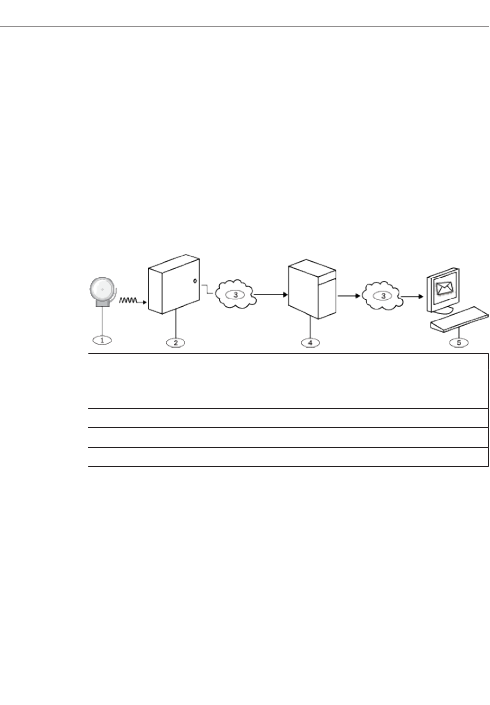
86 en | Panel Wide Parameters Control Panel
2017.03 | 03 | F.01U.323.389 Program Entry Guide Bosch Security Systems, Inc.
3.18 Personal Notification Routing Attempts
Default: 3
Selections: 1-6
This parameter sets the maximum number of attempts the control panel makes to send a
personal notification.
RPS Menu Location
Panel Wide Parameters > Personal Notification > Personal Notification Routing Attempts
3.19 Email Server Configuration
You can program the control panels to send personal notifications to one or more email
addresses (up to 16 destinations).
When an event occurs, the control panel transmits a report across an IP network to an email
server. The SMTP (Simple Mail Transfer Protocol) email server translates the incoming data
into text and then pushes it out to the destinations you programmed. This is a one-way
communication from the control panel to the user.
Callout - Description
1 - Alarm event
2 - Compatible Bosch control panel
3 - Internet
4 - SMTP email server
5 - Computer or other device used to receive email
SMTP Email Servers
SMTP email servers transfer messages to personal notification email addressees.Refer to
Email Server Name/Address for a list of some of the more popular servers and their addresses.
If you can't locate the address for your SMTP email server, contact your email provider.
Setting up an Email Account
To setup an email account that sends emails to the Personal Notification Destinations:
1. Register for an email account from an email provider (example: Google, Yahoo, AOL,
Microsoft).
2. Choose a user name that makes it easy for the individuals receiving the notifications to
identify which emails are coming from the control panel (example: panelacctstore52).
3. Enter the address associated with the SMTP email server you chose in the Email Server
Name/Address parameter.
4. Enter the user name you specified when registering for this account in the Authentication
User Name parameter.
5. Enter the password you specified when registering for this account in the Authentication
Password parameter.

Control Panel Panel Wide Parameters | en 87
Bosch Security Systems, Inc. Program Entry Guide 2017.03 | 03 | F.01U.323.389
3.19.1 Email server name/address
Default: Blank
Selections: Domain name or IP address
This parameter specifies either the domain name or address for the SMTP (Simple Mail
Transfer Protocol) email server for your chosen email provider. The control panel uses the
server's domain name (or address) to transfer event messages from the control panel to
designated personal notification email addressees.
SMTP Email Servers
Refer to the table below for the some of the more popular email providers and their server's
domain name. If your provider doesn't appear in the table, contact them for their domain
name (or IP address).
Email provider Domain name
1&1 smtp.1and1.com
Airmail mail.airmail.net
AOL smtp.aol.com
AT&T outbound.att.net
Bluewin smtpauths.bluewin.ch
BT Connect mail.btconnect.tom
Comcast smtp.comcast.net
Earthlink smtpauth.earthlink.net
Gmail smtp.gmail.com
Gmx mail.gmx.net
HotPop mail.hotpop.com
Libero mail.libero.it
Lycos smtp.lycos.com
O2 smtp.o2.com
Orange smtp.orange.net
Outlook.com (former Hotmail) smtp.live.com
Tin mail.tin.i
Tiscali smtp.tiscali.co.uk
Verizon outgoing.verizon.net
Virgin smtp.virgin.net
Wanadoo smtp.wanadoo.fr
Yahoo smtp.mail.yahoo.com
Further information
IP Address and Domain Name formats, page 254

88 en | Panel Wide Parameters Control Panel
2017.03 | 03 | F.01U.323.389 Program Entry Guide Bosch Security Systems, Inc.
RPS Menu Location
Panel Wide Parameters > Personal Notification > Email Server Configuration > Email Server
Name/Address
3.19.2 Email server port number
Default: 25
Selections: 1-65535
This parameterspecifies the port number for the email server.
Port 25 is the default SMTP port for most outgoing servers. If the IP denies the default port
number (generally because of the massive spam and malware traffic), try another commonly
used port such as port 587 or port 465 to avoid the block.
RPS Menu Location
Panel Wide Parameters > Personal Notification > Email Server Configuration > Email
Server Port Number
3.19.3 Email server authentication/encryption
Default: Authenticate
Selections:
– Basic - no authentication, no encryption
– Authenticate - authentication required, no encryption
– Encrypted - authentication required, encryption required
Use this parameter to set the security level required by the email server to receive messages
from the control panel.
Authentication means that the email server requires an authentication user name and
authentication password.This is sometimes referred to as SMTP-AUTH.
The Encryption used is Secure Sockets Layer (SSL) / Transport Layer Security (TLS)
RPS Menu Location
Panel Wide Parameters > Personal Notification > Email Server Configuration > Email Server
Authentication/Encryption
3.19.4 Authentication user name
Default: Blank
Selections: Blank, 1 to 255 characters
This parameter specifies the user name for the email account that is set up to receive
messages from the SMTP server sent by the control panel.
RPS Menu Location
Panel Wide Parameters > Personal Notification > Email Server Configuration > Authentication
User Name
3.19.5 Authentication password
Default: Blank
Selections: Blank, 1 to 49 characters
This parameter sets the password that the SMTP server uses to send emails to the Personal
Notification destinations.
RPS Menu Location
Panel Wide Parameters > Personal Notification > Email Server Configuration > Authentication
Password

Control Panel Area Wide Parameters | en 89
Bosch Security Systems, Inc. Program Entry Guide 2017.03 | 03 | F.01U.323.389
4 Area Wide Parameters
4.1 Area / Bell Parameters, Open / Close Options
An area is defined as a geographically grouped set of points.
Configurations
Area programming offers a wide selection of different system configurations. The control
panel assigns an account number to each area to define annunciation, control, and reporting
functions. Make area arming conditional on other areas (master or associate), if desired. You
can configure any area for perimeter and interior arming, not requiring a separate area for this
function. Link multiple areas to a shared area which is automatically controlled (hallway or
lobby).
For systems with more than one area, all areas must be under the responsibility of one
ownership and management. This may be a group of buildings attached or unattached and
may even have different addresses but are under the responsibility of someone having mutual
interest (other than the alarm installing company). This does not apply to strip mall
applications where each independent business must have their own separate alarm system.
An example for a commercial system would be a business that has an OFFICE area and a
WAREHOUSE area in a building where each area can be armed or disarmed independently.
As a residential example a system could be configured with the garage and house as separate
areas.
In each of the examples above all of the areas are under the sole responsibility of a single
owner.
In multi-area systems the bell (or siren) and control panel must be in one of the protected
areas.
The bell or siren must be located where it can be heard by users who turn areas on and off
(arm and disarm).
The B6512 supports up to 6 areas.
4.1.1 Area Name Text
Default: Area # (# = the Area number)
Selections: Up to 32 characters
This parameter sets what is displayed at keypads. This is for informational purposes only.
Enter up to 32 characters of text, numbers and symbols to describe the area.
– Keypads display the first 20 characters. If more than 20 characters are used, the area
name text scrolls across the display one time. To scroll the text again, press [ESC].
– Spaces before, after and within a string of text are treated as text and are included in the
32 character limit.
RPS Menu Location
Area Wide Parameters > Area/Bell Parameters, Open/Close Options > Area Name Text
4.1.2 Area Name Text (Second Language)
Default: Blank
Selections: Up to 32 characters
This parameter sets what is displayed at keypads. This is for informational purposes only.
Enter up to 32 characters of text, numbers and symbols to describe the area.
– Keypads display the first 20 characters. If more than 20 characters are used, the area
name text scrolls across the display one time. To scroll the text again, press [ESC].
– Spaces before, after and within a string of text are treated as text and are included in the
32 character limit.

90 en | Area Wide Parameters Control Panel
2017.03 | 03 | F.01U.323.389 Program Entry Guide Bosch Security Systems, Inc.
RPS Menu Location
Area Wide Parameters > Area/Bell Parameters, Open/Close Options > Area Name Text
(Second Language)
4.1.3 Area On
Default:
– B6512:
– Area 1: Yes
– Areas 2 to 6: No
Selections:
– YesArea is enabled.
– No Area is disabled.
This parameter enables or disables the specified area.
Notice!
To comply with UL 864 requirements for Commercial Fire Systems, set this parameter to Yes.
When an area is set to No:
– Points assigned to this area do not generate events.
– When arming and disarming, this area number is not displayed at keypads with the scope
to view this area.
– Status for this area is not reported with status reports.
– All user authority in this area is turned off while the area is disabled.
RPS Menu Location
Area Wide Parameters > Area/Bell Parameters, Open/Close Options > Area On
4.1.4 Account Number
Default: 0000
Selections: 4 or 10 digit numbers, 0-9, B-F
This parameter determines the account number reported for this area. An account number
must be assigned to each active area.
If 5 or more digits are used in the account number, RPS automatically pads the number with
leading zeros to make it a ten-digit number.
Notice!
Make sure the central station automation software is compatible with 10-digit account
numbers before programming a 10-digit account number into the control panel.
Notice!
Account numbers must not include 'A' for any digit.
Account numbers are used to group areas together. Each area can have a different account
number, or several areas might share the same account number. The controlpanel uses the
account number as a reference for arming and keypad text displays.
RPS Menu Location
Area Wide Parameters > Area/Bell Parameters, Open/Close Options > Account Number.
Control Panel Area Wide Parameters | en 91
Bosch Security Systems, Inc. Program Entry Guide 2017.03 | 03 | F.01U.323.389
4.1.5 Force Arm/Bypass Max
Default:2
Selections:
– B6512: 0 to 30
This parameter specifies the maximum number of combined controlled points that can be
faulted or in a bypassed state when arming this area.
Refer to Force Arm Returnable, page 190 and Bypass Returnable, page 190 in the Point Index for
returning a point to the system when the point returns to normal or when the area is
disarmed.
Notice!
Points must have Bypassable, page 191 set to Yes to be bypassed or force armed. Force
arming does not bypass 24-hour points.
Notice!
To comply with UL1610, set this parameter to 0 for wireless keyfobs.
RPS Menu Location
Area Wide Parameters > Area/Bell Parameters, Open/Close Options > Force Arm/Bypass Max.
4.1.6 Delay Restorals
Default:No Delay
Selections:
– No Delay. Point restoral events are logged and reported when the point physically
restores.
– Delay Until Bell Expires. Point restoral events are not logged or reported until the point
has physically restored and the bell silenced or bell time expires.
Use this parameter to delay restoral reports.
For Fire/Gas Alarm/Supervisory points, restoral events are not logged or reported until the
point has physically restored, the bell silenced, and the event cleared from the keypads.
RPS Menu Location
Area Wide Parameters > Area/Bell Parameters, Open/Close Options > Delay Restorals
4.1.7 Exit Tone
Default:Yes
Selections:
– Yes Sound an exit tone at all keypads during exit delay.
– No Turn off exit tones for individual keypads (based on their KP# 1 through 8).
This parameter sounds an exit tone during exit delay at all keypads assigned to this area.
RPS Menu Location
Area Wide Parameters > Area/Bell Parameters, Open/Close Options > Exit Tone
4.1.8 Exit Delay Time
Default:60
Selections:0 to 600 (seconds, in increments of 5)
92 en | Area Wide Parameters Control Panel
2017.03 | 03 | F.01U.323.389 Program Entry Guide Bosch Security Systems, Inc.
This parameter sets the amount of time users have to leave the premises without creating an
alarm event after turning their system All On - Exit or Part On - Exit. They must leave through a
point assigned to a point profile that is configured for a controlled point type with a delayed
alarm response (refer to Point Response, page 179)
Points programmed for instant alarm response generate alarms immediately, even during exit
delay.
Notice!
To comply with SIA CP-01 False Alarm Reduction, set this parameter between 45 and 255
seconds. Refer to SIA CP-01 Verification for more information.
RPS Menu Location
Area Wide Parameters > Area/Bell Parameters, Open/Close Options > Exit Delay Time
4.1.9 Auto Watch
Default:Manual
Selections:
– Manual – users must turn Watch Mode on and off manually from a keypad.
– On at Disarm – the control panel automatically turns Watch Mode on when the area is
turned off (disarmed).
When an area is off (disarmed), Watch Mode is on, and points configured as Watch Point, page
188s are faulted, a watch tone sounds at keypads assigned to the area.
When the area is Part On, only interior points configured as Watch Points sound the watch
tone when they are faulted. Perimeter points report faults as alarms or troubles.
If this Auto Watch parameter is set to Manual and Watch Mode is on when the area is turned
On (armed), Watch Mode will be on when the area is turned off (disarmed).
RPS Menu Location
Area Wide Parameters > Area/Bell Parameters, Open/Close Options > Auto Watch
4.1.10 Restart Time
Default:5
Selections:5 to 55 (seconds) (in 1 second increments)
This parameter sets the length of time to wait for the sensor to stabilize after an alarm
verification point is faulted and the sensor reset has reapplied power to the sensors. This
allows the control panel to double-check alarm verification point activations before generating
alarm signals.
Alarm verification is a feature of automatic fire detection and alarm systems to reduce false
alarms where sensors report alarm conditions for a minimum period of time, or confirm alarm
conditions within a given period of time after being reset, in order to be accepted as a valid
alarm initiation signal.
Notice!
Do not enable the Cross Point Feature in Point Indexes that are designated for fire points.
Notice!
Check the sensor's datasheet for the stabilization time and enter a value at least 5 seconds
higher than the longest time specified by any sensor in the loop.
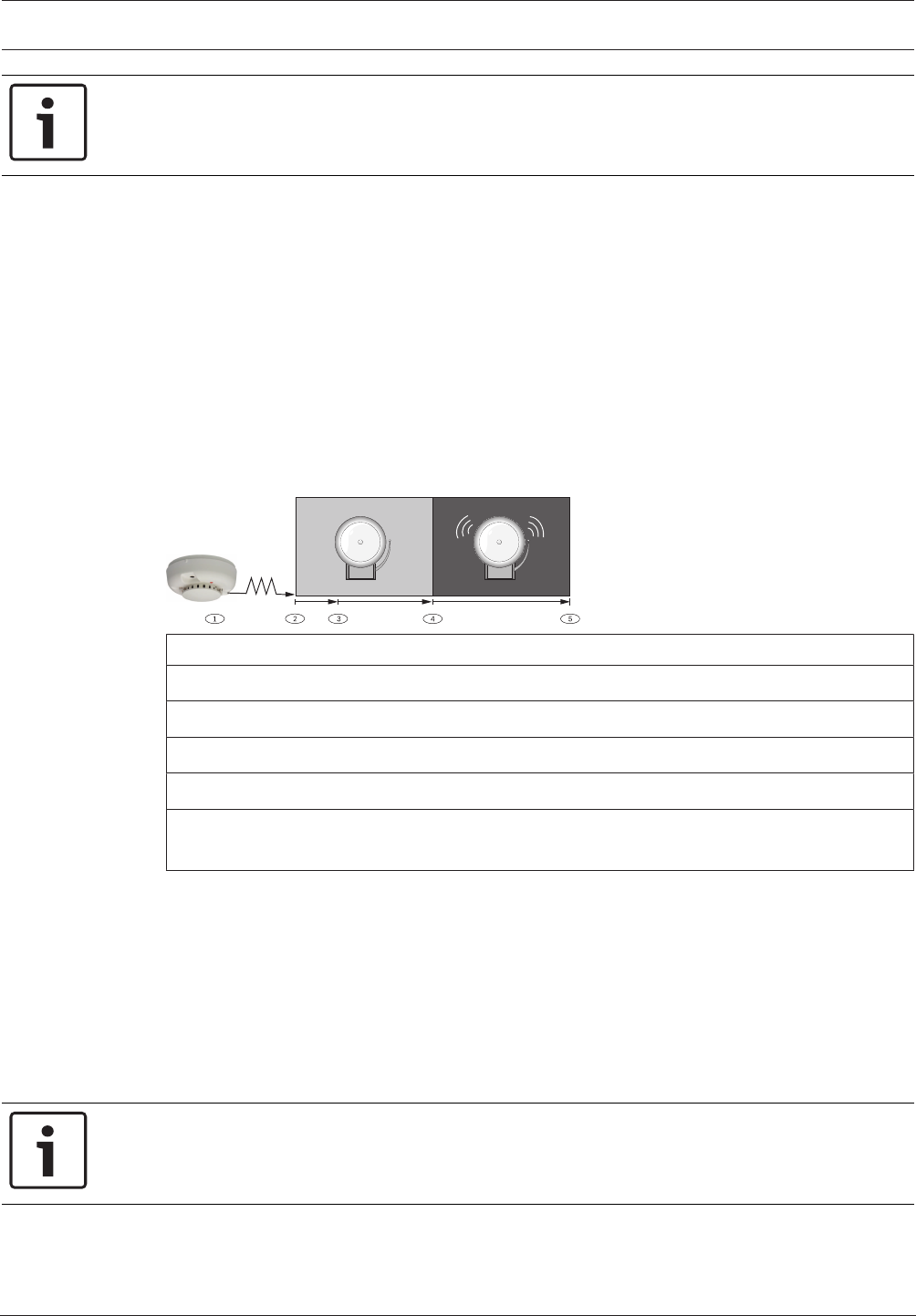
Control Panel Area Wide Parameters | en 93
Bosch Security Systems, Inc. Program Entry Guide 2017.03 | 03 | F.01U.323.389
Notice!
Check with your Authority Having Jurisdiction (AHJ) to determine the maximum verification
time allowed.
Alarm verification points are programmed individually to activate the verification feature. Refer
to Point Index. Any resettable fire point can activate alarm verification for the area to which it
is assigned. Bosch recommends using separate area alarm verification outputs.
To enable alarm verification on a point, set Point Type to Fire, and Alarm Verify and Resettable
to Yes.
When an alarm verification point is faulted, the control panel automatically removes power to
all resettable points connected to the areas Reset Sensors output. Power is removed for 4.5
seconds. When power is reapplied, the control panel ignores alarms from the resettable points
for the amount of time programmed in Restart Time. After Restart Time has expired, a 65
second confirmation window begins. If the alarm verification point is still in alarm, or faults
again during the confirmation window, or if a different alarm verification point in the area
faults, an alarm is generated.
4.5 sec 10-60 sec 65 sec
Callout - Description
1 - Sensor detects possible event.
2 - Power removed from resettable points.
3 - Power reapplied to resettable points. Restart Time begins.
4 - Confirmation window begins. Any alarm during this period will be annunciated.
5 - Confirmation window ends. The sequence is re-initiated the next time an alarm
verification point is faulted.
RPS Menu Location
Area Wide Parameters > Area/Bell Parameters, Open/Close Options > Restart Time
4.1.11 Duress Enable
Default:No
Selections:
– Yes. Enable Duress alarm for this area.
– No. Disable Duress alarm for this area.
This parameter determines if this area allows duress alarms to be generated.
Notice!
To comply with SIA CP-01, set this parameter to Yes.
94 en | Area Wide Parameters Control Panel
2017.03 | 03 | F.01U.323.389 Program Entry Guide Bosch Security Systems, Inc.
If [MENU 35] is used to move the keypad display to an area where this parameter is set to No,
a valid duress disarm passcode does not send a duress report. If you set the parameter to No
in a particular area, the passcode you normally enter for Duress is no longer valid in that area.
If this parameter is set to No, and a passcode with the appropriate disarm authority is used to
duress-disarm the area, NO AUTHORITY appears in the keypad display.
RPS Menu Location
Area Wide Parameters > Area/Bell Parameters, Open/Close Options > Duress Enable
Additional resources
Refer to Duress Type, page 73 for an explanation of Duress
4.1.12 Area Type
Default:Regular
Selections: (selections vary depending on the control panel type)
– Regular - will arm or disarm as an independent area.
– Master - will not allow arming for this area unless all Associate areas with the same A#
Acct Number are exit delay arming or are All On Delay. A Check Area message displays if
the Associate areas have not yet been armed. EXCEPTION: RPS allows Master areas to be
armed without all Associate areas being in the armed state. A Master area can be
disarmed regardless of the armed state of the other areas in the account. Multiple Master
areas can be programmed in a single account.
Notice!
Keypad Scope affects master arming. When arming a master area from a keypad with Keypad
Scope set to Panel Wide or Account Wide, all Associate areas enter Exit Delay as soon as the
Master area is armed. If there is a Shared area within the same account, it begins its Exit
Delay after all Associate areas are armed.
Notice!
Using the arming sked requires that you first use an arming sked to arm the Associate areas
before using an arming sked to arm the Master area. Arming Master areas with RPS,
Keyswitch, or Auto Close parameters occurs before all Associate areas are armed.
– Associate - will allow arming and disarming regardless of the armed state of the other
areas with the same A# Acct Number . This type of area is used with a Master Area and is
associated by having the same account number. Using the arming Sked requires that you
first use an arming Sked to arm the Associate areas before using an arming Sked to arm
the Master area. Keypads assigned to Associate areas, when used in conjunction with
Shared areas, should have the KP# Scope programmed to encompass the Shared Area.
Notice!
Keypads assigned to Associate areas, when used with Shared areas, must have Keypad Scope
programmed.
– Shared - shared areas cannot be armed using a passcode, keyswitch, Sked or by the RPS.
The scope of all Associate areas must include the Shared area(s) in order to view faulted
points. Shared areas:
– Are not associated to other areas by account number, they are shared panel wide.
– Are armed when all Associate areas in the control panel are put into All On Delay
state.

Control Panel Area Wide Parameters | en 95
Bosch Security Systems, Inc. Program Entry Guide 2017.03 | 03 | F.01U.323.389
– Are disarmed when at least one Associate area in the control panel is taken out of All
On Delay state.
Notice!
Arming commands intended for a Shared area must be executed on a keypad with Panel Wide
scope by a user with appropriate authority in all Associate areas. Shared areas associate with
all Associate areas regardless of their account assignments. The shares area does not begin to
arm until all Associates finish arming.
Shared Area Characteristic Description
Arming a Shared Area Requires all Associate areas to be armed. As
soon as the last Associate area is armed, the
Shared area begins its arming sequence
automatically. Shared areas cannot be armed
by passcode, keyswitch or RPS. To allow
faulted points to be displayed at associated
areas, the shared and associate areas must
share the same account number.
Disarming a Shared Area Shared areas automatically disarm when any
Associate area in the control panel is
disarmed. Shared areas cannot be disarmed
by passcode, cards, keyswitch or RPS.
Shared Area Arming Sequence When Shared areas automatically begin to
arm, the arming is based on the A# Exit Dly
Time programmed for the Area # where the
keypad has been assigned.
Shared Area Not Ready If a point is faulted in the Shared area,
[CHECK AREA] will display on the Associate
keypad that is arming the last Associate area.
Associate area keypads can display faults
from Shared areas as long as the Shared
areas fall within the scope of the Associate
area.
Force Arming a Shared Area When [CHECK AREA] is displayed, press the
NEXT key until the Force Arm? prompt is
shown.. Pressing the ENTER key will force
arm the Shared area if: the user has authority
to bypass points, the point is bypassable,
AND the number of faulted points does not
exceed the force arm max amount for the
Shared area. Remember to include the
Shared area in the Associate area's scope.
Viewing Shared Area Armed Status [VIEW AREA STATUS] can be used from a
keypad outside of the Shared area to view
the Shared areas armed state.

96 en | Area Wide Parameters Control Panel
2017.03 | 03 | F.01U.323.389 Program Entry Guide Bosch Security Systems, Inc.
Shared Area Characteristic Description
Silencing Sounders in the Shared Area Shared area alarms and troubles can be
silenced from any keypad.
To silence sounders, the user must have an
authority level assigned to the Shared area.
Access Control Readers Assigned to the
Shared Area
If the entry area is armed and is a Shared
area, then the exit delay will restart and allow
a user to walk to an Associate area and
disarm. If the card reader assigned to the
Shared area includes any Associate area in
the D## KP# Scope (in the ACCESS
CONTROL section, both the Associate area
and Shared area will disarm when the card is
presented.
Closing Reports for Shared Areas If closing reports for Shared areas are
required, Passcodes must also have a valid
authority level assigned in the Shared area.
RPS Menu Location
Area Wide Parameters > Area/Bell Parameters, Open/Close Options > Area Type
4.1.13 Two Man Rule?
Default:No
Selections:
– Yes - two valid and unique passcodes, entered using the same keypad, are required to
disarm the area.
– No - one passcode with a valid authority level can disarm the area.
This parameter sets the requirement for two valid passcodes to be entered on the same
keypad to disarm the area.
Notice!
To comply with SIA CP-01 False Alarm Reduction, set this parameter to No for all enabled
areas. Refer to SIA CP-01 Verification for more information.
Use this parameter in an area that is disarmed from All On using a keypad with Scope, page
109. An alarm event occurs if entry delay ends before the second valid passcode is entered.
If the area is already in an alarm event, the first passcode entry silences the alarm. The second
passcode entry disarms the area.
If the second passcode is entered using a different keypad than the first passcode, the second
keypad displays a warning that the Two Man Rule is already running. Enter both passcodes
using the same keypad.
The area scope that is disarmed is determined by the first passcode that starts the Two Man
Rule?, page 96. A single area keypad (with Scope, page 109) is required for this feature.
You can create a custom function that will disarm the area using passcode disarm.
Set this parameter to Yes in facilities that require a higher level of security to gain access to
the secured area. For example, a bank might enable this parameter to gain access to the vault.
If this parameter is enabled, set the Scope, page 109 parameter for keypads in the affected
areas to "Area Wide."

Control Panel Area Wide Parameters | en 97
Bosch Security Systems, Inc. Program Entry Guide 2017.03 | 03 | F.01U.323.389
You should not set Two Man Rule to Yes in an area that also has Early Ambush?, page 97 set
to Yes.
This function only works when you use passcode disarm.
RPS Menu Location
Area Wide Parameters > Area/Bell Parameters, Open/Close Options > Two Man Rule
4.1.14 Early Ambush?
Default:No
Selections:
– Yes - two valid passcodes are required to disarm the area within the time limit set in the
Early Ambush Time, page 77 parameter.
– No - one passcode with a valid authority level can disarm the area.
This parameter requires two valid passcodes to disarm the area within the time limit set in the
Early Ambush Time, page 77 parameter.
Notice!
To comply with SIA CP-01 False Alarm Reduction, set this parameter to No for all enabled
areas. Refer to SIA CP-01 Verification for more information.
The first passcode entry disarms the area, and the second passcode entry validates the disarm
command. The passcodes can be entered from any two keypads in the area. It is
recommended that you use this parameter when disarming from an All On area, or during the
entry delay period for All On.
You can create a custom function that will disarm the area using passcode disarm. If the
second passcode is not entered before the Early Ambush Time, page 77 ends, the control panel
generates a duress event based on the primary user. You should not set Early Ambush?, page
97 to Yes in an area that also has Two Man Rule?, page 96 set to Yes.
This function only works when you use passcode disarm.
RPS Menu Location
Area Wide Parameters > Area/Bell Parameters, Open/Close Options > Early Ambush
4.1.15 Fire Time
Default:6
Selections:1 to 90 (minutes) (in one minute increments)
This parameter sets the length of time in minutes the bell rings for fire alarm points.
Notice!
Check with your Authority Having Jurisdiction (AHJ) to determine the appropriate bell time
for your geographical area.
The output activated for this time is programmed in A# Fire Bell. The A## Gas Bell is
completely independent of the A## Fire Bell, but also follows the time programmed in this
prompt. The bell output starts as soon as the fire alarm occurs. It shuts off the bell when the
programmed number of minutes expires. Set this parameter for two minutes or more to
ensure you have ample output time.
RPS Menu Location
Area Wide Parameters > Area/Bell Parameters, Open/Close Options > Fire Time

98 en | Area Wide Parameters Control Panel
2017.03 | 03 | F.01U.323.389 Program Entry Guide Bosch Security Systems, Inc.
4.1.16 Fire Pattern
Default:Pulsed
Selections:
– Steady -steady output.
– Pulsed - pulsed march time. 60 beats per minute at an even tempo (0.5 seconds on and
0.5 seconds off).
– California Standard - 10 seconds audible + 5 seconds silent + 10 seconds audible + 5
seconds silent. This sequence repeats until bell time expires.
– Temporal Code 3 - 0.5 seconds On, 0.5 seconds Off, 0.5 seconds On, 0.5 seconds Off, 0.5
seconds On, 1.5 seconds Off; pattern repeats. This sequence repeats for a minimum of 3
minutes with ± 10% timing tolerance. (1999 NFPA standards allow automatic silencing as
permitted by the Authority Having Jurisdiction (AHJ), and carry a minimum ring time of 5
minutes.)
This parameter selects the bell pattern this area uses to signal an alarm on a fire point.
Notice!
When two fire points sharing the same output go into alarm, the bell pattern of the most
recent fire event takes precedence.
RPS Menu location
Area Wide Parameters > Area/Bell Parameters, Open/Close Options > Fire Pattern
4.1.17 Burg Time
Default:6
Selections:1 to 90 (minutes) (in one minute increments)
This parameter sets the number of minutes the bell rings for burglary alarm points.
Notice!
Check with your Authority Having Jurisdiction (AHJ) to determine the appropriate bell time
for your geographical area.
Notice!
To comply with SIA CP-01 False Alarm Reduction, set this parameter to 6 minutes or higher in
all enabled areas. Refer to SIA CP-01 Verification for more information.
The output activated for this time is programmed in A# Alarm Bell, page 129.The bell output
starts as soon as the burglary alarm occurs. It shuts off the bell when the programmed number
of minutes expires. When the control panel's internal clock begins a new minute, it considers
the first minute expired. Set this parameter for two or more minutes.
RPS Menu Location
Area Wide Parameters > Area/Bell Parameters, Open/Close Options > Burg Time
4.1.18 Burg Pattern
Default:Steady
Selections:
– Steady - steady output.
– Pulsed - pulsed march time. 60 beats per minute at an even tempo (0.5 seconds on and
0.5 seconds off).

Control Panel Area Wide Parameters | en 99
Bosch Security Systems, Inc. Program Entry Guide 2017.03 | 03 | F.01U.323.389
– California Standard - 10 seconds audible + 5 seconds silent + 10 seconds audible + 5
seconds silent. This sequence repeats until bell time expires.
– Temporal Code 3 - 0.5 seconds On, 0.5 seconds Off, 0.5 seconds On, 0.5 seconds Off, 0.5
seconds On, 1.5 seconds Off; pattern repeats. This sequence repeats for a minimum of 3
minutes with ± 10% timing tolerance. (1999 NFPA standards allow automatic silencing as
permitted by the Authority Having Jurisdiction (AHJ), and carry a minimum ring time of 5
minutes.)
Select the bell pattern this area uses to signal an alarm on a non-fire point.
RPS Menu Location
Area Wide Parameters > Area/Bell Parameters, Open/Close Options > Burg Pattern
4.1.19 Gas Pattern
Default: Temporal Code 4
Selections:
– Steady. Steady output.
– Pulsed. Pulsed march time. 60 beats per minute at an even tempo (0.5 seconds on and
0.5 seconds
– off).
– California Standard. 10 seconds audible + 5 seconds silent + 10 seconds audible + 5
seconds silent. This sequence repeats until bell time expires.
– Temporal Code 3. 0.5 seconds On, 0.5 seconds Off, 0.5 seconds On, 0.5 seconds Off, 0.5
seconds On, 1.5 seconds Off; pattern repeats. This sequence repeats for a minimum of 3
minutes with ± 10% timing tolerance. (1999 NFPA standards allow automatic silencing as
permitted by the Authority Having Jurisdiction (AHJ), and carry a minimum ring time of 5
minutes.)
– Temporal Code 4. 0.1 seconds On, 0.1 seconds Off, 0.1 seconds On, 0.1 seconds Off, 0.1
seconds On, 0.1 seconds Off, 0.1 seconds On, 5 seconds Off; pattern repeats.
Select the bell pattern this area uses to signal an alarm on a non-fire point.
RPS Menu Location
Area Wide Parameters > Area/Bell Parameters, Open/Close Options > Gas Pattern
4.1.20 Single Ring
Default:No
Selections:
– Yes - this setting produces one bell output per arming period. After one alarm, alarms on
non-fire points in the same area cannot restart the bell until the armed state changes.
– No - restart bell output with each alarm event.
This parameter determines if an alarm from a non-fire point can restart the alarm bell time
with each alarm event, or only initiate alarm output once per arming period.
Notice!
If an alarm occurs on a 24-hour point while the area is disarmed, arming that area with a
keyswitch does not clear the Single Ring flag.
Notice!
Silencing the bell resets Single Ring.

100 en | Area Wide Parameters Control Panel
2017.03 | 03 | F.01U.323.389 Program Entry Guide Bosch Security Systems, Inc.
This parameter does not silence the keypad alarm bell tone or prevent any reports. Fire points
are not affected and bell time is restarted with each new alarm.
RPS Menu Location
Area Wide Parameters > Area/Bell Parameters, Open/Close Options > Single Ring
4.1.21 Bell Test
Default:No
Selections:
– Yes - initiate bell test.
– No - do not initiate bell test.
This parameter provides an alarm output from the output programmed at Alarm Bell, page 129
after the closing report has been confirmed or the exit delay time has expired.
When more than one area is armed at the same time (for example, ARM ALL AREAS? Function
is used), the bell sounds for two seconds with a two-second pause between each bell
activation if all areas have the same exit delay time programmed. Otherwise, the bell test
occurs as each area is armed and it complete its exit delay time. When areas are armed
simultaneously and report to the central station, the bell test occurs as each area is confirmed
by the central station receiver.
Bell Test After Closing Confirmation
In areas that report opening and closing activity, the bell test occurs after the control panel
sends the closing report and receives the acknowledgment from the central station receiver.
For proper operation of the bell test after closing confirmation, the following rules apply:
– The control panel must report opening and closings to the central station.
– Restricted openings and closings, and opening and closing windows, should not be used.
Area Armed Confirmation
In areas that do not report opening and closing activity, the alarm bell output for this area is
activated for two seconds after exit time expires.
RPS Menu Location
Area Wide Parameters > Area/Bell Parameters, Open/Close Options > Bell Test
4.1.22 Account O/C
Default:No
Selections:
– Yes - send opening and closing reports by account. Use this selection if the control panel
sends reports to an automation system that cannot interpret multiple area opening/
closing reports.
– No - do not send opening and closing reports by account.
This parameter determines if account opening and closing reports are generated by this area.
Set this parameter the same for all areas in the account.
An account opening report is generated when the first area in an account is opened
(disarmed). After the account opening report is sent, disarming other areas in the account
does not generate another account opening report. An account closing report is generated
only when the last area in an account is closed (armed). Account opening and closing reports
do not contain any area information.
If an account opening or closing is generated while an opening or closing window for this area
is in effect, and Disable O/C in Window, page 101 is set to Yes, the report is not sent. Bosch
recommends that all areas sharing the same account number use the same opening and
closing window times.
Note: Account numbers are sent over the network to the central station receiver.

Control Panel Area Wide Parameters | en 101
Bosch Security Systems, Inc. Program Entry Guide 2017.03 | 03 | F.01U.323.389
RPS Menu Location
Area Wide Parameters > Area/Bell Parameters, Open/Close Options > Account O/C
4.1.23 Area O/C
Default:Yes
Selections:
– Yes - include the area number and generate opening and closing reports for this area
when it is armed.
– No - do not include the area number or generate opening and closing reports for this
area.
This parameter determines if the area number and the account number are sent upon arming
and disarming.
As long as Account O/C, page 100 is set to No, the account number is sent when arming this
area individually. If Acct O/C is set to Yes, all areas with the same account number must also
be armed. An area opening report is generated when each individual area is opened
(disarmed). An area closing report is generated when each individual area is closed (armed).
Do not set this parameter to Yes if the control panel sends reports to an automation system
that cannot interpret multiple area opening/closing reports.
Opening/Closing Reports are only sent for users with Authority Levels, page 153 assigned as
follows:
– Ready to Arm: Area Open/Close = E
– Not Ready to Arm (Force Arm/Bypass Arm): Restricted Open/Close = E
– Part On Arm: Part On Open/Close = E
RPS Menu Location
Area Wide Parameters > Area/Bell Parameters, Open/Close Options > Area O/C
4.1.24 Disable O/C in Window
Default:Yes
Selections:
– Yes - do not send opening and closing reports to the central station if they occur inside an
active window. If an opening or closing report occurs outside of a window, send it with
an early or late modifier. Refer to O/C Windows.
– The active window must be a closing window for closing reports. It must be an
opening window for opening reports.
– No - send opening and closing reports to the central station even when they occur inside
a programmed window. If an opening or closing occurs outside of the appropriate
window, it reports but does not have an early or late modifier.
– If you want to monitor all opening and closing activity, but you also want to use
features provided by opening and closing windows, set this parameter to No, and
program appropriate O/C windows.
This parameter determines if opening and closing activity is reported when it occurs inside an
opening or closing window as programmed in O/C Windows.
Reports are always logged and printed on a local printer, if installed.
RPS Menu Location
Area Wide Parameters > Area/Bell Parameters, Open/Close Options > Disable O/C in Window
4.1.25 Auto Close
Default:No
Selections:

102 en | Area Wide Parameters Control Panel
2017.03 | 03 | F.01U.323.389 Program Entry Guide Bosch Security Systems, Inc.
– Yes - the area automatically arms All On Delay at the end of the close window. When the
area automatically arms, the control panel sends a closing report if area and/or account
reports are programmed to do so.
– No - do not automatically arm the area at the end of the close window.
With this parameter, the control panel can automatically arm the area All On Delay at the end
of the closing window regardless of the previous armed state.
Regardless of Force Arm/Bypass Max, page 91 or Bypassable, page 191, an unconditional force
arm occurs resulting in faulted points being left out of the system. Refer to Force Arm
Returnable, page 190 or Bypass Returnable, page 190 for details on returning these points to
service.
RPS Menu Location
Area Wide Parameters > Area/Bell Parameters, Open/Close Options > Auto Close
4.1.26 Fail to Open
Default:No
Selections:
– Yes - a Fail to Open report is sent for this area if the area is not disarmed when the
opening window stop time occurs.
– No - a Fail to Open report is not sent for this area.
This parameter allows you to determine if a Fail to Open report is sent for this area. This
parameter can also be used to determine if a user failed to disarm the area before the opening
window expired.
RPS Menu Location
Area Wide Parameters > Area/Bell Parameters, Open/Close Options > Fail To Open
4.1.27 Fail to Close
Default:No
Selections:
– Yes - a Fail to Close report is sent for this area if the area is not armed when the closing
window stop time occurs.
– No - a Fail to Close report is not sent for this area.
This parameter allows you to determine if a Fail to Close report is sent for this area. This
parameter can also be used to determine if a user failed to arm the area before the closing
window expired.
Normal opening and closing reports do not need to be programmed to use this parameter.
An exit delay time must be programmed in Exit Delay Time, page 91.
If Auto Close, page 101 is set to Yes, a report is sent because it occurs when the closing
window stop time occurs.
If Disable O/C in Window, page 101 is set to Yes, Fail to Close report is followed by Closing
Late or Force Close Late report.
RPS Menu Location
Area Wide Parameters > Area/Bell Parameters, Open/Close Options > Fail To Close
4.1.28 Latest Close Time
Default: Disabled
Selections:
– Disabled - RPS sends 0:00 to the control panel.
– 00:30 to 23:30 - set the time for latest close. Set in 30 minute increments using 01 to 24
to specify the hour.
– Midnight - RPS sends 24:00 to the control panel.

Control Panel Area Wide Parameters | en 103
Bosch Security Systems, Inc. Program Entry Guide 2017.03 | 03 | F.01U.323.389
Use this parameter to set a latest close time boundary when an open/close window is
assigned to the selected area.
If the Latest Close Time setting is set to a non-zero value, the time of day specified in the
Close Window Start, page 206 parameter cannot be greater than or equal to the Latest Close
Time setting. For example, if the Latest Close Time parameter is set to 17:30, the Close
Window Start parameter cannot be set to 17:30 or higher.
RPS Menu Location
Area Wide Parameters > Area/Bell Parameters, Open/Close Options > Latest Close Time
4.1.29 Restricted O/C
Default:No
Selections:
– Yes - restrict opening and closing reports for this area. Area O/C, page 101 must be set to
Yes to generate restricted opening and closing reports.
– No - do not restrict opening and closing reports for this area. Regardless of programming
in Restricted O/C , reports are not restricted in this area when this item is set to No.
This parameter determines if opening and closing report activity for this area is restricted.
Was Force Armed and Forced Close events are still sent to the central station if enabled in
routing when force arming the system.
A restricted opening report means the control panel sent an area opening report only when
the area is disarmed after a non-fire/gas alarm.
A restricted closing report means the control panel sent an area closing report only when the
area was All On with controlled points that were faulted during the arming sequence. The
sequence of reports generated by a restricted closing are: Was Force Armed, Forced Point,
Forced Close, then Closing Report.
Opening and Closing reports can be restricted for certain users by configuring the user
authority Restricted Open/Close.
If a passcode is not required for turning the system on, closing reports are always restricted
when A# Restricted O/C is Yes.
If a passcode is required for turning the system on, the user must also be assigned an
Authority Levels, page 153 with Restricted Open/Close = E (enabled) in order for O/C reports
to be restricted.
Open/Close Windows does not prevent restricted opening and closing reports from being
sent. Early or late designations are not added to opening/closing reports when they are sent
according to the rules for restricted opening/closing reports.
RPS Menu Location
Area Wide Parameters > Area/Bell Parameters, Open/Close Options > Restricted O/C
4.1.30 Part On O/C
Default:No
Selections:
– Yes - this area can send Part On opening and closing reports.
– No - this area cannot send Part On opening and closing reports.
This parameter determines if this area can send Part On, Instant and Part On, Delay closing
reports and normal opening reports to the central station.
This event is not suppressed by opening/closing windows.
RPS Menu Location
Area Wide Parameters > Area/Bell Parameters, Open/Close Options > Part On O/C

104 en | Area Wide Parameters Control Panel
2017.03 | 03 | F.01U.323.389 Program Entry Guide Bosch Security Systems, Inc.
4.1.31 Exit Delay Restart
Default:Yes
Selections:
Yes - enable Exit Delay Restart.
No - do not restart Exit Delay.
The Exit Delay Restart feature automatically restarts exit delay when an end-user reenters the
premises before exit delay expires. For example, a home owner turns on (arms) their system,
leaves and closes the door, then realizes they forgot to pick up the car keys. When they open
the door to retrieve their keys, the control panel restarts exit delay, giving them plenty of time
to turn the system off.
With this parameter is set to Yes, following these steps restarts exit delay (Exit Delay Time,
page 91):
1. Turn the system All On or Part On.
2. Fault and restore a point (open and close a door) assigned to a Point Profile configured
for the Point Type, Part On, and a delayed alarm Point Response (4, 5, 6, 7, or 8). (Point
Profiles, page 176, Point Type, page 178, Point Response, page 179)
3. With exit delay still running, fault any point (open a door) assigned to a Point Profile
configured for the Point Type, Part On, and a delayed alarm Point Response (4, 5, 6, 7, or
8). Exit Delay restarts.
Notice!
Exit delay restarts only one time
Exit Delay can only be restarted one time. Faulting the same point a again, or faulting another
point in the restarted exit delay does not restart the delay a second time.
RPS Menu Location
Area Wide Parameters > Area/Bell Parameters, Open/Close Options > Exit Delay Restart
4.1.32 All On- No Exit
Default: Yes
Selections:
Yes – switch the arming state of the area from All On Delay to Part On Delay if no Part On
Delay points are faulted and restored during the exit delay time.
No – keep the arming state of the area All On Delay, whether or not, a Part On Delay point is
faulted and restored during the exit delay time.
This parameter selects whether or not the arming state for an area changes from All On to Part
On if no Part On Delay points are faulted during Exit Delay.
Only the final armed state is reported and displayed at the keypads.
When arming from a keyfob or SKED, the panel ignores this option.
RPS Menu Location
Area Wide Parameters > Area/Bell Parameters, Open/Close Options > All On - No Exit
4.1.33 Exit Delay Warning
Default: No
Selections:
– Yes - pulse the alarm output for the last 10 seconds of Exit Delay
– No - do not pulse the alarm output during Exit Delay
This parameter enables the alarm bell to pulse on and off every two seconds for the remaining
10 seconds of Exit Delay.
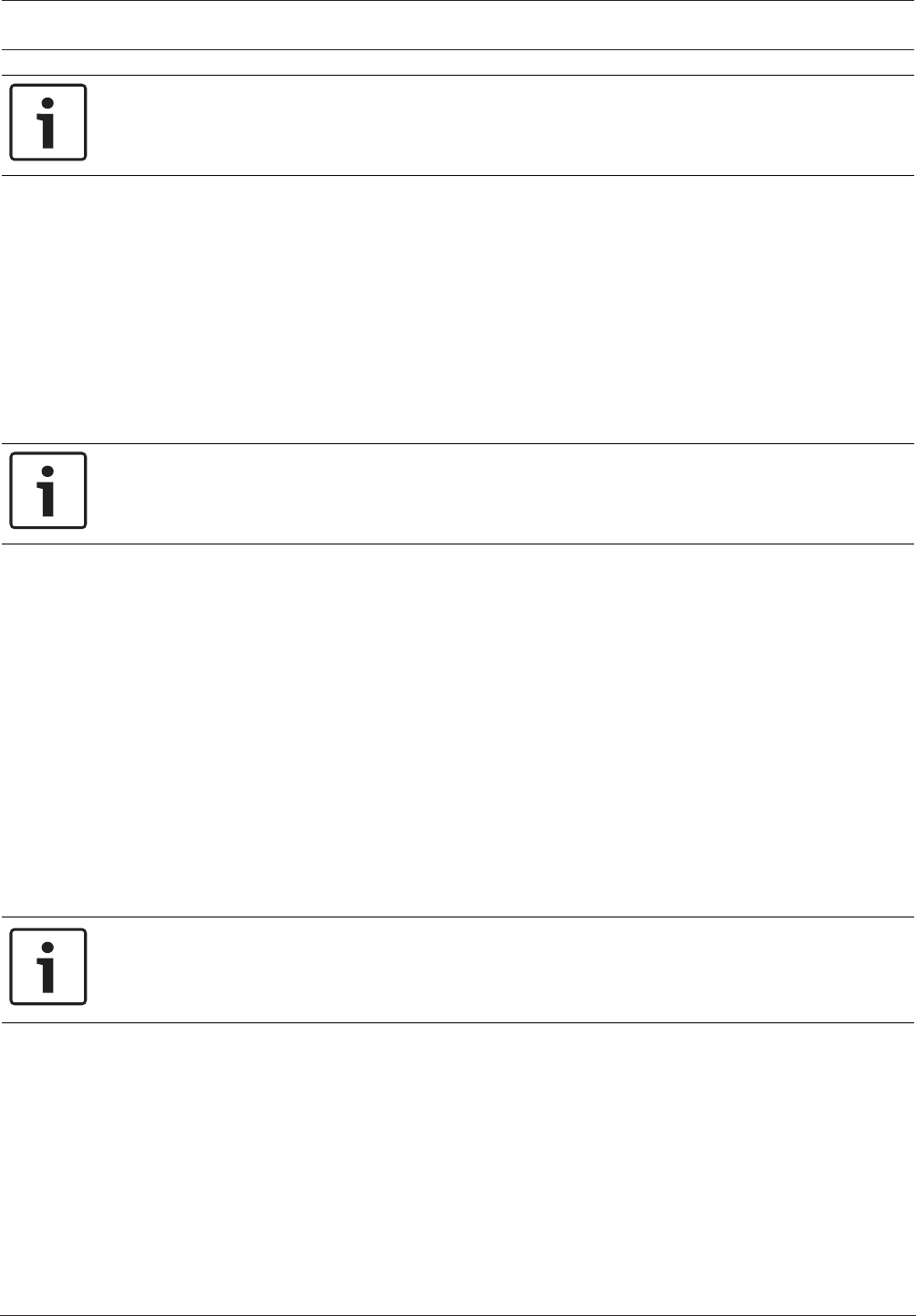
Control Panel Area Wide Parameters | en 105
Bosch Security Systems, Inc. Program Entry Guide 2017.03 | 03 | F.01U.323.389
Notice!
To comply with SIA CP-01 False Alarm Reduction, set this parameter to Yes. Refer to SIA
CP-01 Verification for more information.
RPS Menu Location
Area Wide Parameters > Area/Bell Parameters, Open/Close Options > Exit Delay Warning
4.1.34 Entry Delay Warning
Default: No
Selections:
– Yes - pulse the alarm output for the last 10 seconds of Entry Delay
– No - do not pulse the alarm output during Entry Delay
When this parameter is set to Yes, the alarm bell pulses on and off every two seconds for the
remaining 10 sec of Entry Delay.
Notice!
To comply with SIA CP-01 False Alarm Reduction, set this parameter to Yes. Refer to SIA
CP-01 Verification for more information.
When upgrading a non-control panel account to a control panel account, RPS forces the
default to No.
RPS Menu Location
Area Wide Parameters > Area/Bell Parameters, Open/Close Options > Entry Delay Warning
4.1.35 Area Re-Arm Time
Default:00:00
Selections: 00:00 thru 23:59
00:00 = disabled
This parameter sets the length of time (HH:MM) that a disarmed area delays until it rearms to
All On Delay.
For example if Area Re-Arm Time is set to four hours (04:00) and the area is disarmed (turned
off) at 1:30 pm, it rearms to All On Delay at 5:30 pm. Any points not ready to arm (faulted) are
force armed.
Notice!
Force Arm / Bypass Max is ignored when re-arming
All points not ready to arm (faulted) are force armed when the area re-arms at the end of Area
Re-Arm Time.
The area automatically re-arms at 11:59 pm regardless of when the Area Re-Arm timer started.
For example, if the Area Re-Arm timer is set to 4 hours (04:00) and the area is disarmed
(turned off) at 10:30 pm, the area rearms to All On Delay at 11:59 pm (1 hour and 29 minutes
after disarm).
Users can use Extend Close time from a system keypad to extend an active Area Re-arm delay
(On/Off Menu > Extend Close time).
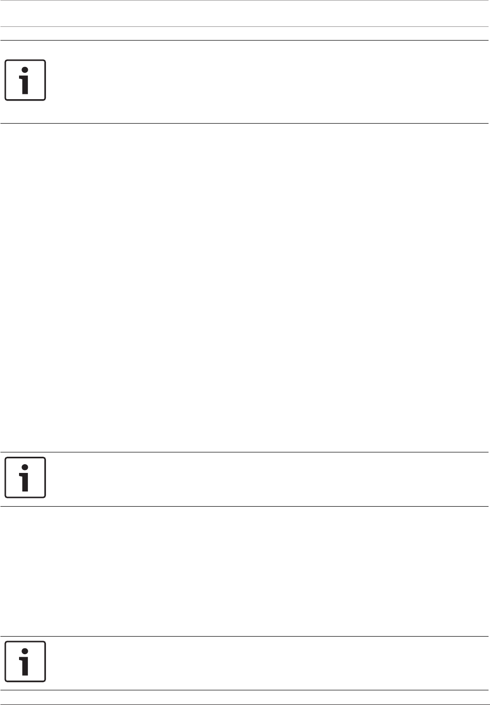
106 en | Area Wide Parameters Control Panel
2017.03 | 03 | F.01U.323.389 Program Entry Guide Bosch Security Systems, Inc.
Notice!
Configuring Closing Window and Area Re-Arm Time may cause unexpected Area behavior.
When both a Closing Window and Area Re-Arm Time are configured for the same area,
the Closing Window is running simultaneously with the Area Re-arm timer,
and a user uses the Extend Close time from a system keypad,
the control panel extends only the Closing Window, not the Area Re-Arm Time.
RPS Menu Location
Area Wide Parameters > Area/Bell Parameters, Open/Close Options > Area Re-Arm Time
4.2 Area Arming Text
The B6512 supports up to 6 areas.
4.2.1 Area name text
Default: Area # (# = the Area number)
Selections: Up to 32 characters
This parameter sets what is displayed at keypads. This is for informational purposes only.
Enter up to 32 characters of text, numbers and symbols to describe the area.
– Keypads display the first 20 characters. If more than 20 characters are used, the area
name text scrolls across the display one time. To scroll the text again, press [ESC].
– Spaces before, after and within a string of text are treated as text and are included in the
32 character limit.
RPS Menu Location
Area Wide Parameters > Area/Bell Parameters, Open/Close Options > Area Arming Text > Area
Name Text
4.2.2 Account is On text
Default: Blank
Selection: Enter up to 32 characters.
This parameter displays the text to display at the keypad for each area as required.
Notice!
When using a D1255F, D1256F, or D1257F keypad, program this parameter as *Fire System*.
RPS Menu Location
Area Wide Parameters > Area/Bell Parameters, Open/Close Options > Area Arming Text >
Account is On Text
4.2.3 Area # is On text
Default: Blank
Selection: Enter up to 32 characters.
This parameter displays the text to display at the keypad for each area as required.
Notice!
When using a D1255F, D1256F, or D1257F keypad, program this parameter as *Fire System*.

Control Panel Area Wide Parameters | en 107
Bosch Security Systems, Inc. Program Entry Guide 2017.03 | 03 | F.01U.323.389
RPS Menu Location
Area Wide Parameters > Area/Bell Parameters, Open/Close Options > Area Arming Text > Area
# is On Text
4.2.4 Area # is not Ready text
Default: Blank
Selection: Enter up to 32 characters.
This parameter displays the text to display at the keypad for each area as required.
Notice!
When using a D1255F, D1256F, or D1257F keypad, program this parameter as *Fire System*.
RPS Menu Location
Area Wide Parameters > Area/Bell Parameters, Open/Close Options > Area Arming Text > Area
# Not Ready Text
4.2.5 Area # is Off text
Default: Blank
Selection: Enter up to 32 characters.
This parameter displays the text to display at the keypad for each area as required.
RPS Menu Location
Area Wide Parameters > Area/Bell Parameters, Open/Close Options > Area Arming Text > Area
# is Off Text

108 en | Keypads Control Panel
2017.03 | 03 | F.01U.323.389 Program Entry Guide Bosch Security Systems, Inc.
5 Keypads
5.1 Keypad Assignments
The B6512 control panel supports SDI2 Keypads 1 to 12.
5.1.1 Keypad Name
Default: Keypad#
Selections: Up to 32 characters
This parameter sets what is displayed at keypads. This is for informational purposes only.
Enter up to 32 characters of text, numbers and symbols to describe the keypad.
– Keypads display the first 20 characters. If more than 20 characters are used, the keypad
name text scrolls across the display one time. To scroll the text again, press [ESC].
– Spaces before, after and within a string of text are treated as text and are included in the
32 character limit.
RPS Menu Location
Keypads > Keypad Assignments > Keypad Name
5.1.2 Keypad Name (Second Language)
Default: blank
Selections: Up to 32 characters
This parameter sets what is displayed at keypads. This is for informational purposes only.
Enter up to 32 characters of text, numbers and symbols to describe the keypad.
– Keypads display the first 20 characters. If more than 20 characters are used, the keypad
name text scrolls across the display one time. To scroll the text again, press [ESC].
– Spaces before, after and within a string of text are treated as text and are included in the
32 character limit.
RPS Menu Location
Keypads > Keypad Assignments > Keypad Name (second language)
5.1.3 Keypad Type
Default:
– Address 1 = B92x Two-line Keypad
– All other addresses = No Keypad Installed
Selections:
– No keypad installed
– B91x Basic Keypad
– B92x Two-line Keypad
– B93x ATM Style Keypad
– B94x Touch Screen Keypad
This parameter identifies the type of keypad that is connected to the control panel at this
address. The information in this parameter is auto-configured when the keypad is first
installed.
RPS Menu Location
Keypads > Keypad Assignments > Keypad Type
Additional Information for fire keypads
Account is On text, page 106
Area # is On text, page 106
Area # is not Ready text, page 107
Area # is Off text, page 107

Control Panel Keypads | en 109
Bosch Security Systems, Inc. Program Entry Guide 2017.03 | 03 | F.01U.323.389
5.1.4 Area Assignment
Default:1 (for all KP addresses)
Selections:
– B6512: 1 to 6
This parameter assigns the keypad to an area.
RPS Menu Location
Keypads > Keypad Assignments > Area Assignment
5.1.5 Keypad Language
Default: First Language, follow User language (for all KP addresses)
Selections:
– First Language, follow User Language
– First Language, ignore User Language
– Second Language, follow User language
– Second Language, ignore User language
This parameter sets the language that is displayed at the keypad.
RPS Menu Location
Keypads > Keypad Assignments > Keypad Language
5.1.6 Scope
Default:
– Address 1: Panel Wide
– All other Addresses: Area Wide
Selections:
– Area Wide – An area keypad is restricted to the viewing information and arming/disarming
functions for the area it is assigned to.
– Account Wide – An account keypad can view information, and perform arming and
disarming functions for all areas that have the same account number. This is normally
used for an associate area.
– Panel Wide – A panel wide keypad can view information and perform arming and
disarming functions for all areas in the control panel. This is normally used with a Master
area.
– Custom – For a custom keypad you select the Areas in Scope.
Use this parameter to define what areas are affected when this keypad is armed, what areas
can be viewed with this keypad, and what areas this keypad can move to.
Whenever the custom scope is changed, RPS shows the following warning dialog:
If you click Yes, RPS resets the Area(s) In Scope parameter.
If you click No, no changes are made in RPS.
RPS Menu Location
Keypads > Keypad Assignments > Scope
Further information
Account Number, page 90
Area Type, page 94
Area in Scope, page 110

110 en | Keypads Control Panel
2017.03 | 03 | F.01U.323.389 Program Entry Guide Bosch Security Systems, Inc.
5.1.7 Area in Scope
Default:
– Address 1: All
– All other Addresses: 1
Selections:
– All All areas within the scope of this keypad are affected.
– 1 Only area 1 is affected.
– Dbl click to view. Areas included within the scope of the keypad have been custom
selected. Double click to view or select custom areas.
This parameter identifies the areas included in the scope of this keypad for viewing status,
arming or disarming.
RPS Menu Location
Keypads > Keypad Assignments > Areas in Scope
Further information
Scope, page 109
5.1.8 Passcode Follows Scope?
Default: Yes (for all KP addresses)
Selections:
– Yes - change the armed state of the areas within the scope of this keypad. If the areas in
the scope are already at the intended armed state, they remain in that state.
– No - view areas within the programmed scope, but only arm or disarm the area
programmed in Area Assignment when a passcode is entered.
This parameter determines whether this keypad follows Scope, or whether it only arms or
disarms the area to which it is assigned. It does not affect the Function List arming and
disarming parameters.
Use this parameter to create a group of account wide keypads that arm only the area
to which they are assigned, even if the user has a passcode with arming authority rights in all
areas.
If the area to which this keypad is assigned is armed, entering a valid passcode disarms this
area and all other areas assigned to the scope of this keypad.
If the area to which this keypad is assigned is disarmed, entering a valid passcode disarms this
area and all other areas assigned to the scope of this keypad. Users must have authority
enabled in Passcode Arm and Passcode Disarm.
RPS Menu Location
Keypads > Keypad Assignments > Passcode Follows Scope
Further information
Scope, page 109
Area, page 173
Arm by Passcode, page 166
Disarm by Passcode, page 166
5.1.9 Enter Key Output
Default:0 (for all keypad addresses)
Selections:
– 0 – no output assigned to Passcode Enter Function, Cycle Output.
– 1-3, 9-96 – assigns output for Passcode Enter Function, Cycle Output.
This parameter assigns an output to Passcode Enter Function, Cycle Output function.

Control Panel Keypads | en 111
Bosch Security Systems, Inc. Program Entry Guide 2017.03 | 03 | F.01U.323.389
When the Passcode Enter Function, page 111 is set to Cycle Output, and a user enters their
passcode and presses [Enter], the output assigned by this parameter cycles (activates for 10
seconds). Two events are added to the panel log: Output ### Set with User ID and, Output
### Reset without User ID.
Notice!
Do not share Enter Key Output with other output functions
The output you assign in this Enter Key Output parameter must not be assigned to any other
output function. Erroneous output operation can result.
You can use the Passcode Enter Function, Cycle Door and the Enter Key Output for a low-level
access control strike on a door. It does not shunt a point.
RPS Menu Location
Keypads > Keypad Assignments > Enter Key Output
Further information
Passcode Enter Function, page 111
5.1.10 Passcode Enter Function
Default:Arm/Disarm (for all KP addresses)
Selections:
– Arm/Disarm - Passcode + [ENTER] starts All On Delay arming for all areas within the users
scope if the current area is disarmed. If the area is not disarmed (off), then all areas in
scope are disarmed.
– Cycle Door - Passcode + [ENTER] cycles the door controller programmed in Assign Door,
page 112 for the Strike Time, page 223 duration, then actuates the users authorized post
access operations (Disarm, Perimeter Instant arm, or execute a Custom Function) if
enabled.
– Cycle Output - Passcode + [ENTER] key activates Enter Key Output, page 110 for 10
seconds.
– Auto Re-Arm - If the area assigned to the keypad is armed All On Delay, passcode +
[ENTER] starts Exit Delay. If the area is Off, passcode + [ENTER] does not arm, the area
remains off.
– Login Only - Passcode + [ENTER] key logs in the user. Dual authentication not enforced.
– Login/Disarm - Passcode + [ENTER] key logs in the user and all armed areas within the
users authorized scope are disarmed. Dual Authentication not enforced.
This parameter defines a single purpose to this keypad; however entry of a passcode with
authority in the current area will always silence alarms and troubles.
When a Passcode Enter Function is unable to be executed due to configuration conflicts, then
the control panel performs the Arm/Disarm function regardless of setting.
The Service Passcode (User ID 0) cannot be used to operate the Passcode Enter Functions.
Outputs used for the Cycle Output function must not be shared with any other point, sensor
reset, control panel, or bell functions. Sharing can cause errors in output operation.
Notice!
To comply with SIA CP-01 False Alarm Reduction, keep this parameter at its default setting.
RPS Menu Location
Keypads > Keypad Assignments > Passcode Enter Function
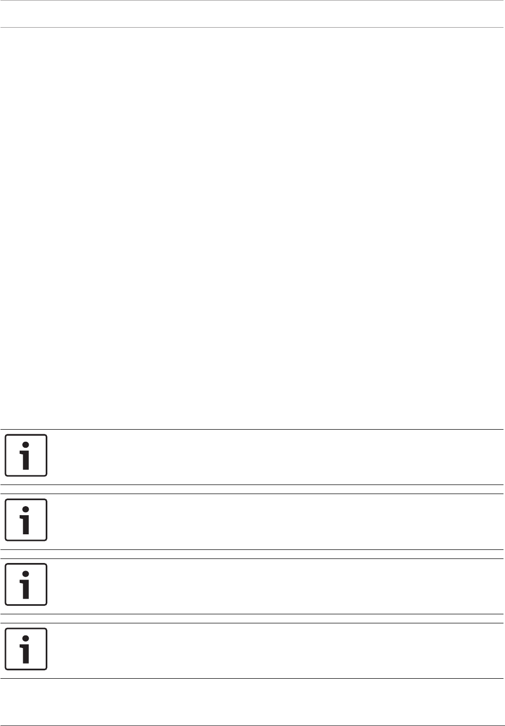
112 en | Keypads Control Panel
2017.03 | 03 | F.01U.323.389 Program Entry Guide Bosch Security Systems, Inc.
5.1.11 Dual Authentication
Default: No
Selections:
This parameter sets the requirement that a user must present any two forms of authorization
(passcode at a keypad, or credential or keyfob to a door reader) in order to gain access.
Before setting this parameter to YES, first Assign Door, page 112 or Keypad Type, page 108.
If the keypad is a B94X Touch Screen and the Assign Door prompt is set to No Door, then the
keypad reader is used for Dual Authentication.
If the keypad is a B94X Touch Screen and the Assign Door prompt is set to Door #, then the
keypad reader is disabled and the door reader is used for Dual Authentication.
RPS Menu Location
Keypads > Keypad Assignments > Dual Authentication
5.1.12 Dual Authentication Duration
Default: 20 Seconds
Selections: 10, 15, 20, 25, 30, 35, 40, 45 seconds
This parameter sets the time out between the presentation of the first and second form of
authorization (passcode, credential or keyfob).
RPS Menu Location
Keypads > Keypad Assignments > Dual Authentication Duration
5.1.13 Assign Door
Default:No Door
Selections: No Door, Door 1 to Door 4
– No Door:No door controller is assigned for adding tokens or the CLOSE DOOR # display
on the keypad.
– 1 - 4: Assign the door controller that enters the Add User? mode when initiated. This door
activates the CLOSE DOOR # display at this keypad if Close Door is set to Yes.
Notice!
The B6512 supports up to 12 keypads.
Notice!
A setting of No Door disables the Cycle Door option of Passcode Enter Function.
Notice!
A setting of No Door disables the Add Card option of the Add/Change User command for this
keypad.
Notice!
A setting of No Door disables Dual Authentication for this keypad.
Enter the door number that is used by this keypad for adding tokens/cards and displaying the
Close Door display.

Control Panel Keypads | en 113
Bosch Security Systems, Inc. Program Entry Guide 2017.03 | 03 | F.01U.323.389
NOT READY appears at this keypad when you are attempting to add a user if a door is not
entered in this parameter and a door is not assigned to the area using the Entry Area, page 219
section. This indicates that access credentials cannot be assigned to a user through the ADD/
CHANGE User command at this keypad until a door number is assigned.
A door does not need to be assigned to a keypad for the user to control the door(s) using the
DOOR CONTROL function. Any door that is active can be controlled by a user who has the
door control authority enabled at a keypad with the doors area, assigned in the ACCESS
CONTROL section, within its scope.
Notice!
During the ADD USER? mode, token/cards, door control requests and RTE/REX do not
function. If there is heavy activity for this door, set the door mode into an unlocked state
before adding users.
RPS Menu Location
Keypads > Keypad Assignments > Assign Door
5.1.14 Trouble Tone
Default:No (for all keypad addresses)
Selections:
– Yes: Panel wide trouble tones sound and visual displays show at this keypad.
– No: Panel wide troubles do not sound. Visual displays still show.
This parameter determines whether this keypad or any keypad with the same address setting,
sounds the panel wide trouble tones.
Panel wide trouble tones include power, phone, SDI2 bus and bus. They do not include point
troubles, or buzz on fault.
RPS Menu Location
Keypads > Keypad Assignments > Trouble Tone
5.1.15 Entry Tone
Default:Yes (for all KP addresses)
Selections:
– Yes: This keypad sounds entry tones.
– No: This keypad does not sound entry tones.
This parameter determines whether this keypad or any keypad with the same address setting
sounds the entry delay tone.
Any delay point within the area scope of this keypad initiates the entry sequence.
This parameter allows you to manage the tone by keypad. Entry tone can also be turned off
when programming Entry Tone Off in Point Index.
Assign two keypads to the same area to have one sound the tone while the other does not.
Set this parameter to Yes for UL installations.
RPS Menu Location
Keypads > Keypad Assignments > Entry Tone
Additional Resource
Entry Tone Off, page 185
5.1.16 Exit Tone
Default: Yes (for all KP addresses)
Selections:
– Yes - this keypad sounds exit tones.

114 en | Keypads Control Panel
2017.03 | 03 | F.01U.323.389 Program Entry Guide Bosch Security Systems, Inc.
– No - this keypad does not sound exit tones.
This parameter determines whether this keypad or any keypad with the same address setting
sounds the exit delay tone during the delay arming of an area.
Any keypad that has a scope to arm this area can initiate the exit tone sequence.
This parameter allows you to manage the tone by keypad. Exit tone can also be turned off
when programming your Exit Tone in Area Parameters.
Assign two keypads to the same area to have one sound the tone while the other does not.
RPS Menu Location
Keypads > Keypad Assignments > Exit Tone
5.1.17 Arm Area Warning Tone
Default:Yes (for all KP addresses)
Selections:
– Yes - this keypad activates a tone and warning display.
– No - this keypad does not activate a tone or warning display.
Use this parameter to determine whether this keypad sounds an audible tone and displays a
warning on the keypad when a closing window has activated.
RPS Menu Location
Keypads > Keypad Assignments > Arm Area Warning Tone
5.1.18 Close Door Warning Tone
Default:Yes (for all KP addresses)
Selections:
– Yes - this keypad activates a tone and warning display.
– No - this keypad does not activate a tone or warning display.
Use this parameter to determine whether this keypad sounds an audible tone and displays the
CLOSE DOOR # warning on the keypad when the door is physically held open past the Shunt
Time, and Extend Time has a value greater than zero for the door assigned to this area in
Assign Door, page 112.
RPS Menu Location
Keypads > Keypad Assignments > Close Door Warning Tone
5.1.19 Idle Scroll Lock
Default: No
Selections:
– Yes - enable Idle Scroll Lock.
– No - allow the control panel's text to auto-scroll.
This parameter prevents auto-scrolling of the keypad's text displaying existing control panel
conditions, such as troubles.
RPS Menu Location
Keypads > Keypad Assignments > Idle Scroll Lock
5.1.20 Function Lock
Default: No (for all KP addresses)
Selections:
– Yes - pressing the Bypass, Menu, or Shortcuts key requires a passcode before proceeding.
– No - pressing the Bypass, Menu, or Shortcuts key does not require a passcode until a
function requiring one is selected.
This parameter determines if the Function Lock requires a passcode when pressed to access
the functions.

Control Panel Keypads | en 115
Bosch Security Systems, Inc. Program Entry Guide 2017.03 | 03 | F.01U.323.389
The user is prompted to enter a passcode after pressing the Bypass, Menu, or Shortcuts key
on the keypad. The items programmed in the function list for this specific keypad are filtered
by the user’s authority level. Only those items in the function list for which the user has
authority appear.
If set to No, when the user presses the Bypass, Menu, or Shortcuts key, all items that are
programmed in the Menu List for the keypad address appear, regardless of the user’s
authority level.
RPS Menu Location
Keypads > Keypad Assignments > Function Lock
5.1.21 Abort Display
Default: Yes (for all KP addresses)
Selections:
– Yes - this keypad displays a message for all aborted alarms within its scope.
– No - this keypad does not display a message for aborted alarms within its scope.
Select whether or not the keypad shows ALARM NOT SENT if the alarm is aborted before an
event report is sent to the central station.
RPS Menu Location
Keypads > Keypad Assignments > Abort Display
5.1.22 Cancel Display
Default: Yes (for all KP addresses)
Selections:
– Yes - this keypad displays a message for all canceled alarms within its scope.
– No - this keypad does not display a message for canceled alarms within its scope.
Select whether or not the keypad displays a message if a burglar alarm is canceled after the
control panel sends a burglar alarm report to the central station.
To show this message, Cancel Reports must be set to Yes. When upgrading a non-control
panel account to a control panel account, RPS forces the default to No.
RPS Menu Location
Keypads > Keypad Assignments > Cancel Display.
Further information
Cancel Reports, page 74
5.1.23 Nightlight Enable
Default: No (for all KP addresses)
Selections: Yes, No
Users with authority to change the keypad display can select whether or not to enable the
nightlight feature on the keypad.
When set to Yes, The display backlight and key backlight (B920, B930) shall remain
illuminated at the minimum level when the keypad is “Idle”.
RPS Menu Location
Keypads > Keypad Assignments > Nightlight Enable
5.1.24 Nightlight Brightness
Default: 2
Selections: 0 to 6
0 = Nightlight off

116 en | Keypads Control Panel
2017.03 | 03 | F.01U.323.389 Program Entry Guide Bosch Security Systems, Inc.
1 to 6 - increases or decreases nightlight brightness. The higher the number, the brighter the
nightlight.
This parameter sets the brightness level for the backlight on the keypad display.
RPS Menu Location
Keypads > Keypad Assignments > Nightlight Brightness
5.1.25 Silence Keypress Tone
Default: No (for all KP addresses)
Selections:
– Yes - disable key press acknowledgement tone. Keypad is silent when buttons are
pressed.
– No - enable key press acknowledgement tone. Users hear a tone each time they press a
button on the keypad.
This parameter enables or disables the key press acknowledgement tone on the keypad.
This option can only be set from RPS.
RPS Menu Location
Keypads > Keypad Assignments > Silence Keypress Tone
5.1.26 Show Date and Time
Default: No (for all KP addresses)
Selections: Yes, No
Users with authority to change the keypad display can select whether or not the keypad
displays the date and time.
RPS Menu Location
Keypads > Keypad Assignments > Show Date and Time
Additional Information
Change Keypad Display, page 159
5.1.27 Keypad Volume
Default: 7 (for all KP addresses)
Selections: 0 to 7
– 0 - the minimum volume setting.
– 1 to 7 - increases or decreases keypress volume. The higher the number, the louder the
tone.
This parameter sets the volume level for the keypress acknowledgement tone on the keypad.
Adjusting the keypad volume in this parameter does not affect the volume of high priority
tones such as alarms which always sound at maximum volume.
RPS Menu Location
Keypads > Keypad Assignments > Keypad Volume
5.1.28 Keypad Brightness
Default: 6
Selections: 0 to 6
0 - Lowest setting
1 to 6 - increases or decreases keypad display brightness. The higher the number, the brighter
the display.
This parameter sets the brightness for the LED display on the keypad. Keypad brightness can
also be set at the keypad.

Control Panel Keypads | en 117
Bosch Security Systems, Inc. Program Entry Guide 2017.03 | 03 | F.01U.323.389
RPS Menu Location
Keypads > Keypad Assignments > Keypad Brightness
5.1.29 Disable Presence Sensor
Default: No
Selections:
– Yes - disable Presence Sensor
– No - enable Presence Sensor
This parameter enables or disables the Presence Sensor on the keypad.
When enabled, the Presence Sensor detects motion within close proximity to the keypad and
brightens a dimmed display as a user approaches.
Available for the B94x Touch screen keypads.
RPS Menu Location
Keypads > Keypad Assignments > Disable Presence Sensor
5.1.30 Disable Token Reader
Default: Yes
Selections:
– Yes - disable Token Reader.
– No - enable Token Reader.
This parameter enables or disables the Credential Reader on the keypad.
Disable when the proximity reader is not in use with the system. Disabling the credential
reader when not in use reduces power consumption. Available for the B94x Touch screen
keypads.
RPS Menu Location
Keypads > Keypad Assignments > Disable Token Reader
5.1.31 Enable Tamper Switch
Default: No
Selections:
– Yes - enable the Tamper Switch.
– No - disable the Tamper Switch.
This parameter is only supported on SDI keypads and the B915. When a legacy keypad is
selected from Keypad Type, page 108, this parameter can be modified. Otherwise it is grayed
out.
RPS Menu Location
Keypads > Keypad Assignments > Enable Tamper Switch
5.1.32 Feature Button Option
Default: Language Selection
Selections:
– Language - allows the user to switch between the first and second languages as
configured under the Panel Info tab of the Panel Data dialog box.
– Event Memory - allows the user to quickly access and view Event Memory.
This parameter sets which feature shows in the upper left corner of a B94x keypad display.
This parameter applies to B94x Touch Screen keypads only.
RPS Menu Location
Keypads > SDI2 Keypad Assignments > Feature Button Option
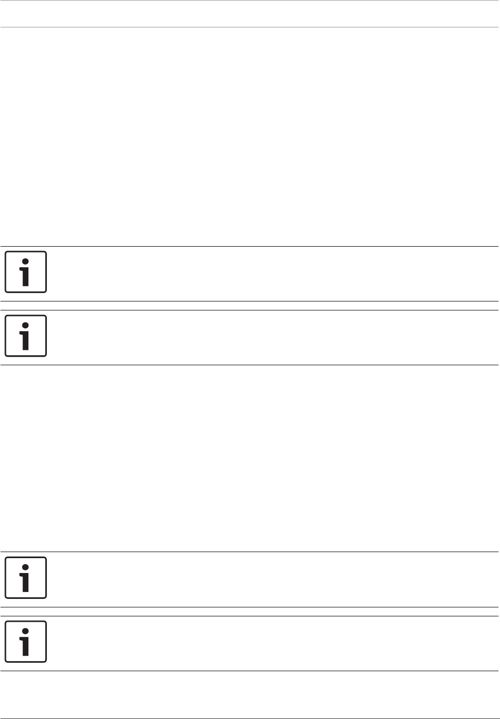
118 en | Keypads Control Panel
2017.03 | 03 | F.01U.323.389 Program Entry Guide Bosch Security Systems, Inc.
5.2 Global Keypad Settings
5.2.1 A key Response
Default: No Response
Selections:
– No Response (Invalid key press response)
– Manual Fire Alarm (When A key and 1 key are held together for 2 sec.)
– Custom Function
This parameter specifies how the control panel responds when the "A" key and 1 key are held
on a keypad that has an "A" key.
An alarm occurs each time the user presses the applicable keys regardless of whether or not
the event has been cleared from the display.
The "A" Key's default function is Manual Fire. To change the function, set this parameter to "A"
Key Custom Function. If the "A" key is configured to execute a custom function, then the "A"
Key Custom Function parameter must also be configured.
Notice!
Enabling the A key response for a FIRE ALARM ALSO enables the keypad CMD 7 response to
generate a fire alarm when you enter CMD 7 from any keypad that has this function enabled.
Notice!
The "A" Key Custom Function option is not available with B942 touch screen keypads.
RPS Menu Location
Keypads > Global Keypad Settings > A Key Response.
5.2.2 A Key Custom Function
Default: Disabled
Selections:
– B6512G: Disabled, Function 128 to Function 133
This parameter specifies the custom function that is run when an "A" key and 1 key are held
together for 2 sec and the "A" key is configured to run a custom function.
If the custom function number is disabled and the "A" key is configured to run a custom
function, holding the "A" key and 1 key generates an invalid key press response.
The number of custom functions supported varies based on the control panel type. Select the
CF# that corresponds to the custom function programmed in Custom Functions.
Notice!
Enabling the A key Custom Function enables the keypad CMD 7 response to activate the
custom function when you enter CMD 7 from any keypad that has this function enabled.
Notice!
The "A" Key Custom Function option is not available with B942 touch screen keypads.
RPS Menu Location
Keypads > Global Keypad Settings > A Key Custom Function
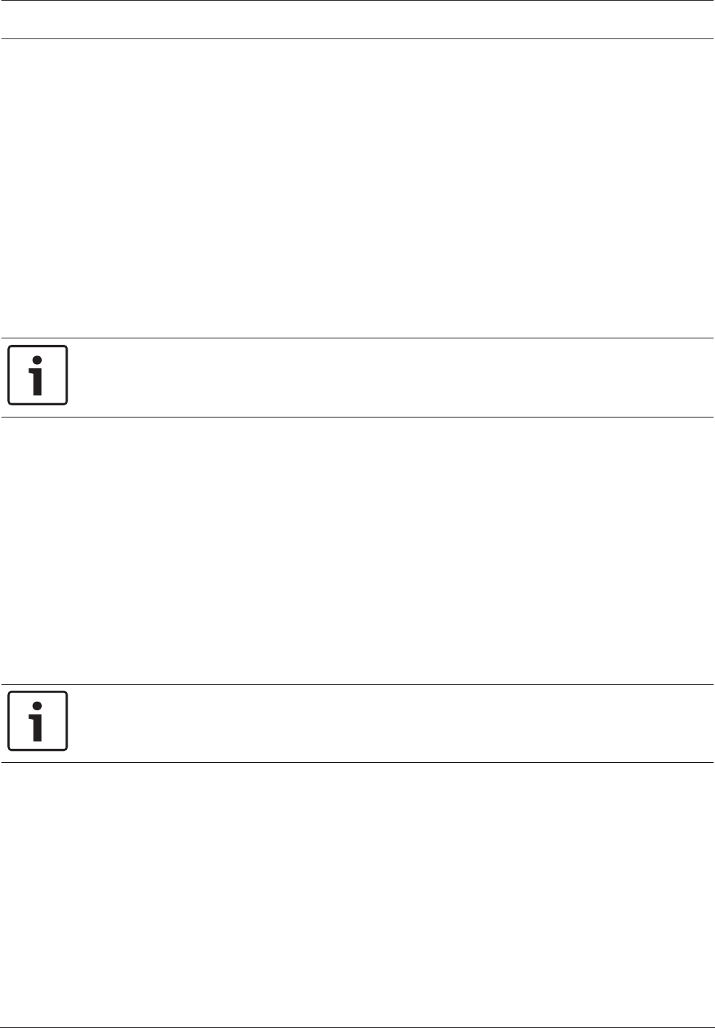
Control Panel Keypads | en 119
Bosch Security Systems, Inc. Program Entry Guide 2017.03 | 03 | F.01U.323.389
5.2.3 B Key Response
Default: No Response
Selections:
– No Response (Invalid key press response)
– Manual Medical Alarm, no Alarm output (when B key and 4 key are held together for 2
sec.)
– Manual Medical Alarm, with Alarm output (when B key and 4 key are held together for 2
sec.)
– Custom Function
This parameter specifies how the control panel responds when the "B" key is held on a keypad
that has a "B" key.
The "B" Key's default function is Medical Alarm. To change the function, set this parameter to
B Key Custom Function, page 119. If the "B" key is configured to execute a custom function,
then the "B" Key Custom Function parameter must also be configured.
Notice!
The "B" Key Custom Function option is not available with B942 touch screen keypads.
RPS Menu Location
Keypads > Global Keypad Settings > B Key Response
5.2.4 B Key Custom Function
Default: Disabled
Selections:
– B6512G: Disabled, Function 128 to Function 133
This parameter specifies the custom function that is run when an "B" key is held and the "B"
key is configured to run a custom function.
If the custom function number is disabled and the "B" key is configured to run a custom
function, holding the "B" key generates an invalid key press response.
The number of custom functions supported varies based on the control panel type. Select the
CF# that corresponds to the custom function programmed in Custom Functions.
Notice!
The "B" Key Custom Function option is not available with B942 touch screen keypads.
RPS Menu Location
Keypads > Global Keypad Settings > B Key Custom Function
5.2.5 C Key Response
Default: No Response
Selections:
– No Response (Invalid key press response)
– Manual Panic Alarm, invisible and silent alarm output (when the C key and 7 are held
together).
– Manual Panic Alarm, visible with alarm output (when the C key and 7 key are held
together).
– Custom Function
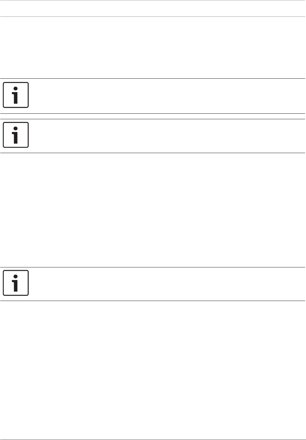
120 en | Keypads Control Panel
2017.03 | 03 | F.01U.323.389 Program Entry Guide Bosch Security Systems, Inc.
This parameter specifies how the control panel responds when a "C" key is held on a keypad
that supports "C" keys. An alarm occurs each time the user presses the applicable keys
regardless of whether or not the event has been cleared from the display.
The "C" Key's default function is Manual Panic Alarm. To change the function, set this
parameter to "C" Key Custom Function. If the "C" key is configured to execute a custom
function, then the "C" Key Custom Function parameter must also be configured.
Notice!
Enabling the C Key Response for a panic alarm also enables the keypad CMD 9 response to
generate a panic alarm when you enter CMD 9 from any keypad that has this function
enabled.
Notice!
The "C" Key Custom Function option is not available with B942 touch screen keypads.
RPS Menu Location
Keypads > Global Keypad Settings > C Key Response
5.2.6 C Key Custom Function
Default: Disabled
Selections:
– B6512G: Disabled, Function 128 to Function 133
This parameter specifies the custom function that is run when a "C" key is held and the "C"
key is configured to run a custom function.
If the custom function number is disabled and the "C" key is configured to run a custom
function, holding the "C" key generates an invalid key press response.
The number of custom functions supported varies based on the control panel type. Select the
CF# that corresponds to the custom function programmed in Custom Functions.
Notice!
The "C" Key Custom Function option is not available with B942 touch screen keypads.
RPS Menu Location
Keypads > Global Keypad Settings > C Key Custom Function
5.2.7 Manual Silent Alarm Audible on Comm Trouble
Default: No
Selections:
– Yes Enable the Alarm Bell to activate when the silent alarm event fails to reach central
station.
– No Disables the Alarm Bell from activating when the silent alarm fails to reach central
station.
This parameter enables the Alarm Bell output to activate for the remaining Burg Bell time if a
keypad or RADION keyfob silent alarm fails in two attempts to transmit its report to the
configured destination.

Control Panel Keypads | en 121
Bosch Security Systems, Inc. Program Entry Guide 2017.03 | 03 | F.01U.323.389
The Alarm Bell outputs activated are the same outputs that would have been activated if the
keypad or RADION keyfob alarm had been configured as a panic alarm. The bell timer was
started when the silent alarm was generated so the Alarm Bell is only active for the configured
Burg Time minus the time it took to attempt to report twice.
This option only has an effect if a keypad's C key or a RADION keyfob panic is configured to
create a silent alarm.
RPS Menu Location
Keypads > Global Keypad Settings > Manual Silent Alarm Audible on Comm Trouble
5.2.8 Comm Trouble Options
Default: Comm Troubles are Audible and Visible
Selections:
– Comm Troubles are Silent and Invisible
– Comm Troubles are Audible and Visible
When this parameter is set to Comm Troubles are Audible and Visible, communication trouble
events show at keypads and activate the trouble tone.
When this parameter is set to Comm Troubles are Silent and Invisible, communication trouble
events do not show at keypads. They do not activate the trouble tone.
Notice!
Enable trouble tone for each keypad
Use the Trouble Tone, page 113 parameter in Keypad assignments to enable panel wide
trouble tones (including the Comm Trouble) for individual keypads. The default for all keypad
addresses for the Trouble Tone parameter is No (panel wide troubles do not sound).
RPS Menu Location
Keypads > Global Keypad Settings > Comm Trouble Sound Options
5.3 Global Wireless Keyfob
5.3.1 Keyfob Function A Custom Function
Default: Disabled
Selections:
– B6512G: Disabled, Function 128 to Function 133
This parameter specifies the custom function that is run when the Auxiliary Function A button
is pressed on the RADION keyfob.
On the RADION four-button keyfobs, pressing the third button activates Auxiliary Function A.
When the auxiliary function button is pressed, the control panel performs the custom function
configured in this parameter. If it is configured as disabled, then no action occurs.
RPS Menu Location
Keypads > Global Wireless Keyfob > Keyfob Function A Custom Function
5.3.2 Keyfob Function B Custom Function
Default: Disabled
Selections:
– B6512G: Disabled, Function 128 to Function 133
This parameter specifies the custom function that is run when the Auxiliary Function B button
is pressed on the keyfob.
On the RADION four-button keyfobs, pressing the fourth button activates Auxiliary Function B.
When the auxiliary function button is pressed, the control panel performs the custom function
configured in this parameter. If it is configured as disabled, then no action occurs.

122 en | Keypads Control Panel
2017.03 | 03 | F.01U.323.389 Program Entry Guide Bosch Security Systems, Inc.
RPS Menu Location
Keypads > Global Wireless Keyfob > Keyfob Function B Custom Function
5.3.3 Keyfob Panic Options
Default: Panic response disabled
Selections:
– Panic response disabled - the control panel ignores all panic button presses from every
keyfob.
– Audible panic response enabled - when a panic button is pressed on any keyfob the
control panel activates an audible tone at the keypads and activates the Alarm Bell
output.
– Silent panic response enabled - when a panic button is pressed on any keyfob the control
panel activates the Silent Alarm output and keypads remain silent.
The keyfob panic response is enabled or disabled globally. The outputs activate for the Burg
Time configured in their respective areas. If the Alarm Bell is active, silencing the alarm logs a
Cancel event. No alarm abort window is supported.
When an audible panic response is generated, a Burg Alarm is indicated and sounded on all
keypads that have scope over the areas where the alarm bell is active. The control panel logs a
Keyfob Panic Alarm event. The user number associated with the keyfob is logged with the
event. No restoral event is logged.
Keyfob panic alarm events have a configuration option enabling or disabling their reporting by
route group. This option is available only from RPS in PANEL WIDE PARAMETERS > Report
Routing. This option controls the reporting of both Keypad Panic Alarms and Keyfob Panic
Alarms.
When a silent panic response is generated, the control panel activates the Area Wide Output >
Duress Output in each area that the keyfob user has authority. The outputs activate for the
Burg Time configured in their respective areas.
If the duress output is active, silencing the alarm logs a Cancel event. No alarm abort window
is supported. When a silent panic response is generated, there is no indication or sound on
any keypad. When a silent panic response is generated, the control panel logs a Key Fob Silent
Alarm event. The user number associated with the keyfob is logged with the event. No restoral
event is logged for a keyfob Silent Alarm.
Keyfob silent alarm events have a configuration option, separate from the keyfob panic alarms,
enabling or disabling their reporting by route group. This option is available only from RPS in
PANEL WIDE PARAMETERS > Report Routing. This option controls the reporting of both
Keypad Silent Alarms and keyfob Silent Alarms.
RPS Menu Location
Keypads > Wireless keyfob > keyfob Panic Options

Control Panel Custom Functions | en 123
Bosch Security Systems, Inc. Program Entry Guide 2017.03 | 03 | F.01U.323.389
6 Custom Functions
Each Custom Function ### item has an 18 character programmable text. When the custom
function is assigned to the Shortcut Menu Function the user can use the PREV or NEXT key to
scroll to the Custom Function Text.
The user must have the appropriate authority level enabled for the Custom Function in the
User Configuration section, to be capable of using the custom function.
The B6512 supports 6 custom functions
6.1 Custom Function Text
Default: Function ###
Selection: Enter up to 32 characters of text, numbers and symbols.
– SDI2 keypads display the first 20 characters. If more than 20 characters are used, the text
scrolls across the display one time. To scroll the text again, press [ESC].
– Spaces before, after and within a string of text are treated as text and are included in the
32 character limit.
This parameter sets the menu text displayed at the keypad for the Custom Function item.
RPS Menu Location
Custom Function > Custom Function Text
6.2 Custom Function Text (Second Language)
Default: Blank
Selections: Enter up to 32 characters of text, numbers and symbols.
This parameter sets the menu text displayed at the keypad for the Custom Function item when
the user, keypad, or system is configured to use the second language.
SDI2 keypads display the first 20 characters. If more than 20 characters are used, the text
scrolls across the display one time. To scroll the text again, press [ESC].
Spaces before, after and within a string of text are treated as text and are included in the 32
character limit.
RPS Menu Location
Custom Function > Custom Function Text (second language)
6.3 Functions
Default: Not in Use
Selections: Refer to the list below.
Use these Function parameters (Function 1 to Function 6) to assign up to six functions to a
custom function.
Double click in the Function 1 (to Function 6) field to show the function selection dialog box.
Some functions require you to configure one or two parameters. For example, if you select the
Disarm function, you select which areas to disarm in Parameter 1.

124 en | Custom Functions Control Panel
2017.03 | 03 | F.01U.323.389 Program Entry Guide Bosch Security Systems, Inc.
Notice!
When a Custom Function initiates, assigned functions run in order, 1 to 6
The control panel runs the functions assigned to a custom function consecutively. The panel
starts functions immediately after starting the previous function. It does not wait for the
previous function to finish.
Use the Delay function selection to create a delay between the start of two functions.
Parameter 1 configures the length of the delay (1 to 90 seconds).
For example: To toggle an output at the end of a Part On Delay with a 30 second exit delay,
set Function 1 to "Part On Delay", set Function 2 to "Delay" with Parameter 1 set to greater
than 30 seconds, and set Function 3 to "Toggle Output".
Notice!
Special Force Arm / Bypass Max rules for arming with Custom Functions
When a Custom Function includes an arming function (All On Delay, All On Instant, Part On
Instant, Part On Delay) special rules for the Force Arm/Bypass Max, page 91 limit for faulted
points apply.
If a user activates the Custom Function from a keypad using a shortcut or function key, from
an RF Keyfob, or by presenting their credential (card or token) to a reader or keypad,
and the Custom Function requires a passcode (Custom Function, page 152 = P),
then the control panel enforces the Force Arm / Bypass Max limit for faulted points. If the
number of faulted points exceeds the Force / Arm Bypass Max limit, the function fails The
control panel does not arm the Area. There is no indication at keypads for the failed function.
The control panel includes the user number in the arming event (history log and report).
If a user activates a Custom Function from a keypad using a shortcut or function key, from an
RF Keyfob, or by presenting their credential (card or token) to a reader or keypad,
and the Custom Function does not require a passcode (Custom Function, page 152 = E),
then the control panel enforces the Force Arm / Bypass Max limit for faulted points. If the
number of faulted points exceeds the Force / Arm Bypass Max limit, the function fails The
control panel does not arm the Area. There is no indication at keypads for the failed function.
The control panel does not include the user number in the arming event (history log and
report).
If a custom function is activated by a Sked, point, or automation, the control panel does not
enforce the Force Arm / Bypass Max limit for faulted points. The control panel arms all faulted
points, even if the Force Arm / Bypass Max limit is exceeded.
FUNCTION:
Click on a function name for information about that function.
Not In Use - This function is disabled and no functions after this will be performed.
All On Delay, page 213
All On Instant, page 214
Part On Delay, page 214
Part On Instant, page 214
Disarm, page 214
Extend Close, page 214
Bypass a Point, page 214
Unbypass a Point, page 214
Unbypass All Points, page 214
Reset Sensors, page 214
Turn Output On, page 214
Turn Output Off, page 215

Control Panel Custom Functions | en 125
Bosch Security Systems, Inc. Program Entry Guide 2017.03 | 03 | F.01U.323.389
Toggle Output, page 215
One-Shot Output, page 215
Reset All Outputs, page 215
Delay, page 215
Cycle Door
Unlock Door
Lock Door
Secure Door
Access Ctrl Level
Access Granted Events
Access Denied Events
Answer RPS, page 215
Contact RPS, page 215
Contact RPS User Port, page 216
Send Status Report, page 216
Send Test Report, page 216
Send Test on Off Normal, page 217
Go to Area, page 217
Watch On, page 217
Watch Off, page 217
Show Date & Time, page 217
Sound Watch Tone, page 217
Set Keypad Volume, page 218
Set Keypad Brightness, page 218
Trouble Silence, page 218
Alarm Silence, page 218
RPS Menu Location
Custom Function > Function 1-6

126 en | Shortcut Menu Control Panel
2017.03 | 03 | F.01U.323.389 Program Entry Guide Bosch Security Systems, Inc.
7 Shortcut Menu
7.1 Function
Default:
– Shortcut Menu Item 1: All On Selected Area
– Shortcut Menu Item 2: Off Select Area
– Shortcut Menu Item 3: View Point Status
– Shortcut Menu Item 4: Reset Sensors
– Shortcut Menu Item 5: Change Watch Mode
– Shortcut Menu Item 6: Brightness (SDI2) / Dim (SDI)
– Shortcut Menu Item 7: Volume (SDI2) / Dim (SDI)
– Shortcut Menu Item 8: View Log
– Shortcut Menu Item 9-32: Disabled Item
Selections:Refer to table below.
This parameter assigns functions to menu items.
Select the function from the drop down list in the dialogue box that appears when you double-
click a cell in the Function column and next to the function in the User Configuration section.
All supported custom functions are listed by their configured Custom Function Text, page 123.
There is no restriction on how many times you might assign a specific function to the menu. By
doing so, you can assign the same function at different keypads so they appear in a different
order in some areas than they would in others.
Function Function Function
Disabled Item
All On Delay
All On Instant
All On Select Area
Part On Delay
Part On Instant
Part On Select Area
Off
Off Select Area
Extend Close
Bypass a Point
Unbypass a Point
View Area Status
View Point Status
Send Status Report
Reset Sensors
Change Output State
Fire Walk Test
Intrusion Walk Test
Service Walk Test
Invisible Walk Test
Send Test Report
Display Revisions
RPS Answer
RPS via Network
RPS via Network, Change
Port
RPS via Phone
Go to Area
Update Firmware
View Service Bypassed
Cycle Door
Unlock Door
Lock Door
Secure Door
Change Passcode
Add User
Edit User
Delete User
Change Watch Mode
Set Panel Date
Set Panel Time
Show Date/Time
Change Skeds
Brightness (SDI2)
Volume (SDI2)
Keypad Nightlight
Silence Key Tone
View Event Memory
Delete Event Memory
View Log
A Key Alarm (Fire)
B Key Alarm (Medical)
C Key Alarm (Silent/Panic)
Function ### (128 to 133)
RPS Menu Location
Shortcut Menu > Function
7.2 Set/Clear all
Default: Set/Clear All

Control Panel Shortcut Menu | en 127
Bosch Security Systems, Inc. Program Entry Guide 2017.03 | 03 | F.01U.323.389
Selections: Address 1-32
Use this parameter to quickly enable or disable a selected function number at all available
addresses or select set several addresses at once without the need to set each one
individually.
Any changes you make in the Set/Clear All window also appear in the specific keypad Address
# cell. For example, if you check the boxes for Address 1 and Address 2 in the Set/Clear All
Address window, the cells for Address 1 and Address 2 change to show Yes. Likewise, if you
change any of the Address #, page 127 cells individually, those changes appear in the Set/Clear
All Address window.
RPS Menu Location
Shortcut Menu > Set/Clear All
7.3 Address #
Default: Yes (Shortcut Menu 1 to 8)
Selections:
– Yes - this menu item appears at this keypad address.
– No - this menu item does not appear at this keypad address.
This parameter determines at which keypad address setting this menu item appears.
Any changes you make in the Set/Clear all, page 126 window also appear in the specific keypad
Address # cell. For example, if you check the boxes for Address 1 and Address 2 in the Set/
Clear All Address window, the cells for Address 1 and Address 2 change to show Yes.
Likewise, if you change any of the Address # cells individually, those changes appear in the
Set/Clear All Address window.
RPS Menu Location
Shortcut Menu > Address # (B6512: 1 to 12, B5512, B4512: 1 to 8, B3512: 1 to 4)
Shortcut Menu > Address # (B9512: 1 to 32, B8512: 1 to 16)

128 en | Output Parameters Control Panel
2017.03 | 03 | F.01U.323.389 Program Entry Guide Bosch Security Systems, Inc.
8 Output Parameters
Outputs provide dry contact (normally open/closed) outputs for LED annunciation and other
applications as well as wet (12vdc on/off) voltage outputs for basic alarm system functions
(such as Bell output, Reset Sensors, etc.). The applications are endless, but primarily, outputs
are used to enhance a systems capability to perform output functions.
Output Types
– Panel Wide Outputs: These outputs are used to provide an output related to a "panel
wide" indication. For annunciation, these outputs can be used to indicate "system wide"
troubles for power, phone and overall control panel summary of alarms, troubles and
supervisory events.
– Area Outputs: These outputs are used to provide an output "by the area" that the output
is assigned to. An area can have its own bell and sensor reset indications. Outputs can
also be used to indicate the area armed state and whether any off normal events such as
a force arm have occurred.
– On-board Outputs: There are 2 on-board 12 VDC voltage-outputs which provide power
when activated on the control panel. These outputs are default programmed from the
factory as outputs A(1), B(2) and C(3). Typically, output A(1) is used for the Bell, output
B(2) is used for an alternate alarm output (such as another bell) and output C(3) is used
for Sensor Reset.
Off-board Outputs: The control panel can also control as many as 64 dry contact form "C"
outputs when up to 8 optional B308 OctoOutput Modules are installed. These outputs are
used for Area Output, Panel Wide Output, and Individual Point Fault Outputs.
Output Follows Point
Outputs can also be used to activate when a point programmed for, Output Response Type (in
the point index section), is off normal or in alarm event.
Output Reports
When output activity is reported to the receiver (Refer to Routing ), on-board outputs are
reported as follows: A(1) = 253, B(2) = 254, C(3) = 255, and others report as 001 to 58. The
output report is Relay Set Output #rrrr when the output is turned ON and Relay Set Output
#rrrr when the output is turned off. Output reports are also stored in the control panel
memory log.
Controlling Outputs
As mentioned, outputs can be activated depending upon events that exist with the control
panel. In addition, outputs can be controlled by the user using the [CHG OUTPUT?] function,
Output On/Output Off skeds, and the RPS.
The following programming tips, notes and applications are important for you to review prior
to programming your outputs.
Notice!
Do not attempt to use the CHG OUTPUTS? function to toggle outputs reserved for special
functions. Special function outputs are Area and control panel Wide output functions as well
as outputs assigned to KP# Entr Key Rly and Output Response Type.
Output C is always powered ON. Assigning any other output deactivates Output C so this
output can be used for other functions. When Output C is programmed for Reset Sensors,
power is always supplied from the AUX terminal of the control panel and the Output C
provides a path to common. Output C turns off the common connection during sensor reset.
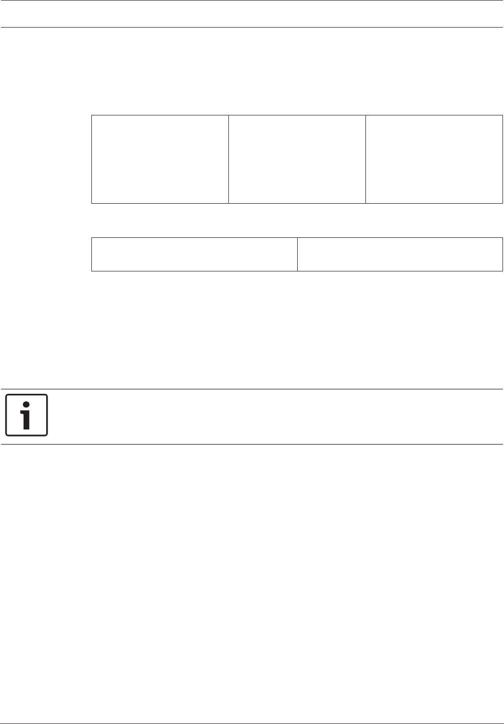
Control Panel Output Parameters | en 129
Bosch Security Systems, Inc. Program Entry Guide 2017.03 | 03 | F.01U.323.389
Check output status after reprogramming or resetting the control panel. All outputs are turned
off after the control panel is reset. Certain output functions are checked by the control panel
each minute and will resume the correct state after the reset. Other outputs must be manually
set to the correct state using the Change Output function (MENU 32).
These output functions resume the proper state within one minute:
Fire Bell
Summary Fire
Summary Trouble
Silent Alarm
Summary SupFire
Summary Fire Tbl
Area Fault
Summary Alarm
Phone Fail
Watch Mode
Alarm Bell
Area Armed
Part On Fault
AC Fail
Communications Fail
Reset Sensors
Battery Trouble
Summary SupBurg
These output functions need to be manually reset with Change Output function:
Fail To Close
Duress
Force Armed
Log % Full
8.1 Area Wide Outputs
8.1.1 Alarm Bell
Default:1
Selections:
– B6512: 0 to 96
This output activates when an intrusion point assigned to this area goes into alarm. It will also
activate for (non-fire) keypad and keyfob alarms that are configured to sound the Alarm Bell.
Notice!
To comply with SIA CP-01 False Alarm Reduction, set this parameter to a value other than 0
for each enabled area. Refer to SIA CP-01 Verification for more information.
Burg Time, page 98 and Burg Pattern, page 98 must be programmed. This output activates
according to the bell pattern and remains active until the bell time expires or is manually
silenced. Silent Alarm, page 132 must be set to No in order for the bell to ring upon alarm.
Each area can be assigned a unique output number for each of the events listed in this
section.
RPS Menu Location
Output Parameters > Area Wide Outputs > Alarm Bell
8.1.2 Fire Bell
Default:1
Selections:
– B6512: 0 to 96
This output activates when a fire point assigned to this area goes into alarm. It will also
activate for keypad fire alarms.
Fire Time and Fire Pattern must be programmed in Bell Parameters. This output activates
according to the bell pattern and remains active until the bell time expires or is manually
silenced. Silent Bell must be set to No in order for the bell to ring upon alarm.
Each area can be assigned a unique output number for each of the events listed in this
section.

130 en | Output Parameters Control Panel
2017.03 | 03 | F.01U.323.389 Program Entry Guide Bosch Security Systems, Inc.
Notice!
To comply with UL 864 requirements for Commercial Fire Systems, program this parameter
with a relay.
RPS Menu Location
Output Parameters > Area Wide Outputs > Fire Bell
8.1.3 Reset Sensors
Default:3
Selections:
– B6512: 0 to 96
This parameter (output C) output de-activates for five seconds when the RESET SENSORS?
function is initiated from the keypad or during a FIRE WALK? test.
The Reset Sensor time converts from the five second default time to the time programmed in
Restart Time (Area parameters section) when a point programmed for Alarm Verify, page 193
(Point Index Section) goes into an alarm event.
When sharing one output to reset sensors in two or more areas, you must program the
parameters below. Failure to do so can cause TROUBLE PT ### for all point types programmed
as Resettable, page 193.
–Scope, page 109 must include all the areas that are sharing the output.
–Reset Sensor(s), page 162 for the user initiating the sensor reset must be enabled in all
the areas that are sharing the output.
–Restart Time, page 92 must be the same number of seconds for all the areas that are
sharing the output.
Each area can be assigned a unique output number for each of the events listed in this
section.
RPS Menu Location
Output Parameters > Area Wide outputs > Reset Sensors
8.1.4 Fail to Close/Part On Armed
Default:0
Selections:
– B6512: 0 to 96
To change between the Fail To Close and Part On output functions described below, configure
the Part On Output, page 80 parameter.
This output activates when the closing window expires for the specified area. It remains
activated until midnight, or until another closing window starts, or the control panel is reset,
whichever occurs first.
Each area can be assigned a unique output number for each of the events listed in this
section.
This output activates when all areas assigned to the same output are armed Part On Instant or
Part On Delayed.
RPS Menu Location
Output Parameters > Area Wide Outputs > Fail to Close/Part On
8.1.5 Force Armed
Default:0
Selections:
– B6512: 0 to 96

Control Panel Output Parameters | en 131
Bosch Security Systems, Inc. Program Entry Guide 2017.03 | 03 | F.01U.323.389
This output activates when this area is force armed. It remains activated until the area is
disarmed or the control panel is reset. This output does not activate when Part On force
arming.
Each area can be assigned a unique output number for each of the events listed in this
section.
RPS Menu Location
Output Parameters > Area Wide Outputs > Force Armed
8.1.6 Watch Mode
Default:0
Selections:
– B6512: 0 to 96
This output activates when a controlled point programmed for Watch Point is tripped in the
specified area while the area is in Watch Mode and the point is not armed. It remains activated
for two seconds after each point is faulted.
Each area can be assigned a unique output number for each of the events listed in this
section.
RPS Menu Location
Output Parameters > Area Wide Outputs > Watch Mode
8.1.7 Area Armed
Default:0
Selections:
– B6512: 0 to 96
The output activates when the specified area becomes All On (exit delay must expire before
the output activates). The output remains activated until the area is disarmed, it does not
deactivate during the entry delay time.
If multiple areas use the same output, the output activates when all areas are armed. It
deactivates when the first area disarms.
– Keyswitch area armed status with LED's. Use an module and connect an LED to display
the armed state.
– Alternate communication trigger: This output can be used to trigger the input zone of a
device being used as a slave to report control panel arming status.
Each area can be assigned a unique output number for each of the events listed in this
section.
RPS Menu Location
Output Parameters > Area Wide Outputs > Area Armed
8.1.8 Area Off
Default: 0
Selections:
– B6512: 0 to 96
When an area's arming state switches from All On (either delay or instant) to Part On or
Disarmed, the output number configured here activates.
When an area's arming state switches from Part On or Disarmed to All On (either delay or
instant), the output number configured here de-activates.
If the same output number is configured in more than one area's Area Off Output, the output
will only activate when the first area is no longer armed All On. If the same output number is
configured in more than one area's Area Off Output, the output will only de-activate if all
area's using that same output number are armed All On.

132 en | Output Parameters Control Panel
2017.03 | 03 | F.01U.323.389 Program Entry Guide Bosch Security Systems, Inc.
The Area Off Output is also affected by the Early Area Armed Output, page 81. When the Early
Area Armed Output is set to No,the Area Off Output does not activate until the end of exit
delay. When the Early Area Armed Output is set to Yes, the Area Off Output de-activates as
soon as exit delay starts and the area is armed All On.
Note: if the All On- No Exit, page 104 option is set to Yes and the area switches to Part On at
the end of exit delay, the Area Off Output will activate at that time.
Simply starting entry delay does not affect the state of the output configured in Area Off.
RPS Menu Location
Output Parameters > Area Wide Outputs > Area Off
8.1.9 Area Fault
Default:0
Selections:
– B6512: 0 to 96
The output activates whenever a Part On, Interior or Interior Follower point is faulted. The
output remains activated until all perimeter and interior points in the area are normal.
Keyswitch area fault status with LED's: Use a B308 module and connect an LED to illuminate
when this output is activated indicating that the area is not ready to arm.
Assign a unique output number for each area.
RPS Menu Location
Output Parameters > Area Wide Outputs > Area Fault
8.1.10 Duress Output
Default:0
Selections:
– B6512: 0 to 96
The output activates when a duress event is generated from a keypad assigned to the area.
Burg Time must have a bell period programmed and Duress Enable, page 93 must be set to Yes.
This output activates "steady" regardless of bell pattern and remains active until the bell time
expires.
You can assign a different output number for the Duress Output each area.
RPS Menu Location
Output Parameters > Area Wide Outputs > Duress Output
8.1.11 Part On Fault
Default:0
Selections:
– B6512: 0 to 96
The output activates when a controlled perimeter point (Type 1) assigned to the specified
area is faulted. This output activates regardless of the areas armed state.
This output provides a steady output until all perimeter points in the area return to normal.
This output does not activate on interior faults. To detect all area point faults, program all
points as perimeter points in the area to which this output is assigned.
Assign a unique output number for each area.
RPS Menu Location
Output Parameters > Area Wide Outputs > Part On Fault
8.1.12 Silent Alarm
Default:0
Selections:

Control Panel Output Parameters | en 133
Bosch Security Systems, Inc. Program Entry Guide 2017.03 | 03 | F.01U.323.389
– B6512: 0 to 96
This output activates when a point assigned to the specified area and programmed for Silent
Bell, page 186 goes into alarm.
Use this output for invisible/silent bell 24-hour panic/hold up applications.
RPS Menu Location
Output Parameters > Area Wide Outputs > Silent Alarm
8.1.13 Gas Bell
Default: 1
Selections:
– B6512: 0 to 96
This output activates when a gas point assigned to this area goes into alarm.
The area-wide Gas alarm bell uses the time in Fire Time, page 97 and output cadence defined
in Gas Pattern, page 99. This output activates according to the bell pattern and remains active
until the bell time expires or is manually silenced.
Each area can be assigned a unique output number for each of the events listed in this
section.
RPS Menu Location
Output Parameters > Area Wide Outputs > Gas Bell
8.2 Panel Wide Outputs
8.2.1 AC Failure
Default:0
Selections:
– B6512: 0 to 96
This parameter enables the output to activate when the control panel responds to an AC
power failure as programmed in AC Fail Time, page 69. The output automatically resets when
AC power is restored.
Connect a separate sounder to this output to create an audible annunciation from the keypads
for all applications excluding commercial fire systems.
RPS Menu Location
Output Parameters > Panel Wide Outputs > AC Failure
8.2.2 Battery Trouble
Default:0
Selections:
– B6512: 0 to 96
This parameter enables the output to activate when battery voltage falls below 12.1 VDC, or
when the battery is in a missing condition. The output automatically resets when battery
power is restored.
Connect a separate sounder to this output to create an audible annunciation from the keypads
for all applications excluding commercial fire systems.
RPS Menu Location
Output Parameters > Panel Wide Outputs > Battery Trouble
8.2.3 Phone Fail
Default:0
Selections:
– B6512: 0 to 96

134 en | Output Parameters Control Panel
2017.03 | 03 | F.01U.323.389 Program Entry Guide Bosch Security Systems, Inc.
This parameter enables the output to activate when a telephone line failure alarm is
generated. The output automatically resets when the telephone line restores.
A time must be entered in Phone Supervision Time in order for this output to activate.
RPS Menu Location
Output Parameters > Panel Wide Outputs > Phone Fail
8.2.4 Comm Fail
Default:0
Selections:
– B6512: 0 to 96
When there is a Comm Fail event for any Route Group the output you enter at this parameter
activates. The output automatically resets when a report from the Route Group is sent to the
central station receiver successfully. To learn more about Comm Fail events refer to
Communicator, overview, page 58.
RPS Menu Location
Output Parameters > Panel Wide Outputs > Comm Fail
8.2.5 Log % Full
Default:0
Selections:
– B6512: 0 to 96
This parameter sets the number of the output that activates when the log has reached the
programmed percentage of its capacity as programmed in Log % Full, page 70. A steady
output is provided until the RPS pointer is set.
RPS Menu Location
Output Parameters > control panel Wide Outputs > Log % Full (Outputs)
Additional resources
See Get History for more information.
8.2.6 Summary Fire
Default:0
Selections:
– B6512: 0 to 96
This parameter sets the number of the output that activates when any fire point in the system
(Point type = Fire) goes into alarm. A steady output is provided until all fire points in the
system are returned to normal, and all fire alarm events are cleared from keypad displays.
Notice!
This parameter only functions as described when Fire Summary Sustain, page 76 is set to No.
Notice!
To ensure proper operation, do not assign more than one function to the output associated
with this summary function.
RPS Menu Location
Output Parameters > Panel Wide Outputs > Summary Fire
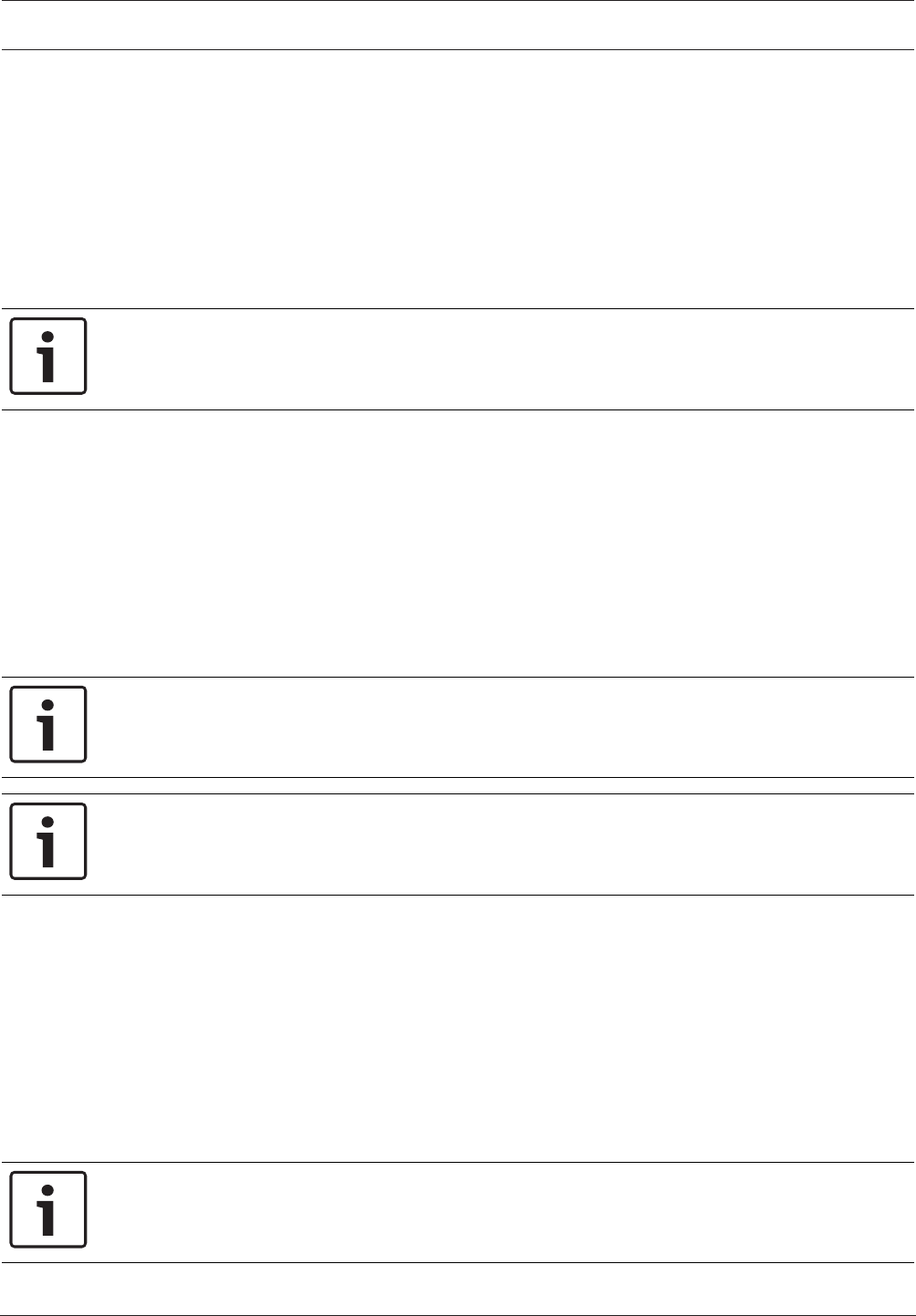
Control Panel Output Parameters | en 135
Bosch Security Systems, Inc. Program Entry Guide 2017.03 | 03 | F.01U.323.389
8.2.7 Summary Alarm
Default:0
Selections:
– B6512: 0 to 96
This parameter sets the number of the output that activates when a non-fire point goes into
alarm.
A steady output is provided until the alarm is silenced and the alarm event is cleared form the
keypads' display.
This output does not activate for silent alarms.
Notice!
To ensure proper operation, do not assign more than one function to the output associated
with this summary function.
RPS Menu Location
Output Parameters > Panel Wide Outputs > Summary Alarm
8.2.8 Summary Fire Trouble
Default:0
Selections:
– B6512: 0 to 96
This parameter enables the output to activate when any fire point on the control panel is in
trouble. A steady output is provided until all fire points have restored to a normal event and
the event message is cleared by the user at the keypad.
Notice!
To ensure proper operation, do not assign more than one function to the output associated
with this summary function.
Notice!
Fire/gas trouble points must be restored to normal before summary outputs can be cleared.
RPS Menu Location
Output Parameters > Panel Wide Outputs > Summary Fire Trouble
8.2.9 Summary Supervisory Fire
Default:0
Selections:
– B6512: 0 to 96
This output activates when any fire supervisory point on the control panel is in a supervisory
event (off normal). A steady output is provided until all fire supervisory points are restored to
a normal condition and the event message is cleared by the user at the keypad.
Notice!
To ensure proper operation, do not assign more than one function to the output associated
with this summary function.
136 en | Output Parameters Control Panel
2017.03 | 03 | F.01U.323.389 Program Entry Guide Bosch Security Systems, Inc.
Notice!
Fire/gas trouble points must be restored to normal before summary outputs can be cleared.
RPS Menu Location
Output Parameters > Panel Wide Outputs > Summary Supervisory Fire
8.2.10 Summary Trouble
Default:0
Selections:
– B6512: 0 to 96
This parameter output activates when any non-fire/gas point on the control panel is in a
trouble condition. A steady output is provided until the event message is cleared by the user
at the keypad.
Notice!
To ensure proper operation, do not assign more than one function to the output associated
with this summary function.
Notice!
Fire/gas trouble points must be restored to normal before summary outputs can be cleared.
RPS Menu Location
Output Parameters > Panel Wide Outputs > Summary Trouble
8.2.11 Summary Supervisory Burg
Default:0
Selections:
– B6512: 0 to 96
This parameter enables the output to activate when any non-fire supervisory point on the
control panel is in a supervisory condition. A steady output is provided until all Burg points are
restored to a normal condition and the event message is cleared by the user at the keypad.
Notice!
To ensure proper operation, do not assign more than one function to the output associated
with this summary function.
Notice!
Fire/gas trouble points must be restored to normal before summary outputs can be cleared.
RPS Menu Location
Output Parameters > Panel Wide Outputs > Summary Supervisory Burg
8.2.12 Summary Gas Output
Default: 0
Selections:
Control Panel Output Parameters | en 137
Bosch Security Systems, Inc. Program Entry Guide 2017.03 | 03 | F.01U.323.389
– B6512: 0 to 96
This parameter sets the number of the output that activates when any gas point in the system
goes into alarm. A steady output is provided until all gas points in the system are returned to
normal and the event message is cleared by the user at the keypad.
Notice!
To ensure proper operation, do not assign more than one function to the output associated
with this summary function.
Notice!
Fire/gas trouble points must be restored to normal before summary outputs can be cleared.
RPS Menu Location
Output Parameters > Panel Wide Outputs > Summary Gas Output
8.2.13 Summary Gas Supervisory Output
Default: 0
Selections:
– B6512: 0 to 96
This parameter enables the output to activate when any gas supervisory point on the control
panel is in a supervisory event (off normal). A steady output is provided until all gas
supervisory points are restored to a normal condition and the event message is cleared by the
user at the keypad.
Notice!
To ensure proper operation, do not assign more than one function to the output associated
with this summary function.
Notice!
Fire/gas trouble points must be restored to normal before summary outputs can be cleared.
RPS Menu Location
Output Parameters > Panel Wide Outputs > Summary Gas Supervisory Output
8.2.14 Summary Gas Trouble Output
Default: 0
Selections:
– B6512: 0 to 96
This parameter sets the output to activate when any gas point on the control panel is in
trouble. A steady output is provided until all gas points have restored to a normal condition
and the event message is cleared by the user at the keypad.
Notice!
To ensure proper operation, do not assign more than one function to the output associated
with this summary function.
138 en | Output Parameters Control Panel
2017.03 | 03 | F.01U.323.389 Program Entry Guide Bosch Security Systems, Inc.
Notice!
Fire/gas trouble points must be restored to normal before summary outputs can be cleared.
RPS Menu Location
Output Parameters > Panel Wide Outputs > Summary Gas Trouble Output
8.3 Output Configuration
8.3.1 Output Source
Default:
– Output A(1): On-board A
– Output B(2): On-board B
– Output C(3): On-board C
– All other Outputs: Unassigned
Selections:
– On-board
– Unassigned
– Octo-output
– IP Camera
– Keypad
This parameter guides the RPS operator with configuration rules, such as where the Octo-
output devices are allowed to be configured, and what output number ranges are permitted.
When a selection is grayed out it cannot be changed.
You can install a B308 Octo-output Module on particular Output number boundaries starting
at Output 11. Refer to B308 Octo-output Module switch settings, page 250.
Notice!
Use of IP Camera as Output Source is limited
Each IP Camera (1 to 6 ) supports 4 outputs. You can select IP Camera as Output Source for
Outputs 11 to 14, 21 to 24, 31 to 34, …61 to 64 only.
Do not select IP Camera as Output Source for Outputs 15 to 18, 25 to 28, 35 to 38, …65 to
68.
RPS Menu Location
Output Parameters > Output Configuration > Output Source
8.3.2 Output Text
Default: Output #
Selections: Up to 32 alphanumeric characters
This parameter provides a description for the physical location of the point for use by
installation and service personnel. Enter up to 32 characters of text to describe the output.
Note: To expand or collapse the list of Point numbers, use the arrows at the top of the RPS
screen.
RPS Menu Location
Output Parameter > Output Configuration > Output Text
8.3.3 Output Text (Second Language)
Default: Blank
Selections: Up to 32 alphanumeric characters

Control Panel Output Parameters | en 139
Bosch Security Systems, Inc. Program Entry Guide 2017.03 | 03 | F.01U.323.389
This parameter provides a description for the physical location of the point for use by
installation and service personnel. Enter up to 32 characters of text to describe the output.
Note: To expand or collapse the list of Point numbers, use the arrows at the top of the RPS
screen.
RPS Menu Location
Output Parameter > Output Configuration > Output Text-Second Language
8.3.4 Hide From User
Default: No
Selections:
– Yes - The control panel denies access to this output for all users except the installer.
– No - The control panel allows authorized end users to toggle the output manually at a
keypad, or by using RSC, Automation Mode 1, or Automation Mode 2.
This parameter gives the installer the ability to hide outputs from user control.
Note: To expand or collapse the list of Point numbers, use the arrows at the top of the RPS
screen.
RPS Menu Location
Output Parameter > Output Configuration > Hide from User

140 en | User Configuration Control Panel
2017.03 | 03 | F.01U.323.389 Program Entry Guide Bosch Security Systems, Inc.
9 User Configuration
9.1 User Assignments (passcodes)
9.1.1 User Name
Default:
– User 0: Installer
– All others: USER #
Selections: Up to 32 characters.
This parameter sets the user name displayed at keypads, and included in user reports when
transmitting in Modem4 format to the central station receiver.
Enter up to 32 characters of text, numbers and symbols.
Keypads display the first 20 characters. If more than 20 characters are used, the name scrolls
across the display one time. To scroll the name again, press [ESC].
Spaces before, after and within the name are treated as text and are included in the 32
character limit.
To expand or collapse the list of users, use the arrows at the top of the RPS screen.
RPS Menu Location
User Configuration > User Assignments > User Name
9.1.2 Passcode
Default:
– User 0: 123
– User 1: 123456
– All others: Blank
Selections:Enter a 3-to-6-digits based on the entry made in Passcode Length, page 78.
This parameter sets a value from three to six digits in length to enable a passcode for the
Master User in this group.
You cannot enter any passcode number that could conflict with a duress passcode. Regardless
of the Duress Type, page 73 setting, passcodes within a range of 2 for existing passcodes
cannot be entered. This rule applies even if duress is disabled. For example, once a passcode
of 654327 is entered, 654325, 654326, 654328, and 654329 cannot be entered.
A silence bell authority is built into all authority levels, even if they are default and none of the
available programmable functions are enabled. A user passcode can silence a Fire/Burg bell as
long as any authority level is assigned to the area where the bell can be silenced from.
User 000 is the Service Authority Level (Level 15). You cannot change the programming for
User 000. Only the Service Authority Level (User 000) can delete User 000. When a user other
than User 000 tries to delete the passcode for User 000, the keypad displays NOT IN USE.
User 000 cannot be added or changed at the keypad.
Note: To expand or collapse the list of users, use the arrows at the top of the RPS screen.
RPS Menu Location
User Configuration > User Assignments (Passcodes) > Passcode
9.1.3 Remote Access
Default: No (prohibit this user system access with RSC application)
Selections:
– Yes (allow this user system access with RSC application)
– No (prohibit this user system access with RSC application)

Control Panel User Configuration | en 141
Bosch Security Systems, Inc. Program Entry Guide 2017.03 | 03 | F.01U.323.389
When this parameter is set to Yes, the user can use the RSC (Remote Security Control)
application on their mobile device to control their security system.
When this parameter is set to No, the user is prohibited from using the RSC (Remote Security
Control) application on their mobile device to control their security system.
RPS Menu Location
User Configuration > User Assignments > Remote Access
9.1.4 User Group
Default:0
Selections:
– B6512: 0 to 6
0 = no restrictions
This parameter creates a group of users whose combinations can be enabled/disabled using
an automatic user window. This is the number that is entered into the User Group, page 208
(Schedules > User Group Windows) for any active user window.
Multiple windows can be programmed for one user group within one 24 hour period. For
example, if User Group 1 has a window running from 8:00 AM (start time) to 4:00 PM (stop
time), the users for that group can use their passcodes only between 8:00 AM and 4:00 PM.
Between 4:00 PM and 8:00 AM the next day, the users cannot use their passcodes.
To enable this user's passcode at all times, leave this item 0.
User Group Window times cannot be changed from the keypad. Once a window is assigned to
a user group, the users in that group rely on the window to be active (within the start and
stop times) for their passcodes to function. The only way to disable the window is by
reprogramming the control panel from RPS.
Note: To expand or collapse the list of users, use the arrows at the top of the RPS screen.
RPS Menu Location
User Configuration > User Assignments (Passcodes) > User Group
9.1.5 Area Authorities
Default:
– User 0: All Area #'s Authority Level = 15
– User 1:
– Area #1 Authority Level = 1
– All other Area #'s Authority Level = 0
– All Other User #'s: 0
Selections:
– B6512: 0 to 6
Notice!
When setting up a new User, assign an authority level to the user for at least one area. The
Area Authorities parameter defaults to 0 (zero) for new users. Authority Level 0 (zero) means
the user has no authority in the area indicated. Authority level 15 is reserved for User 0-
Installer and cannot be changed.
0 = No Authority
Refer to User Configuration > Authority Levels, page 153 in RPS to view settings for each
authority level.
Note: To expand or collapse the list of users, use the arrows at the top of the RPS screen.

142 en | User Configuration Control Panel
2017.03 | 03 | F.01U.323.389 Program Entry Guide Bosch Security Systems, Inc.
RPS Menu Location
User Configuration > User Assignments > Area Authorities
9.1.6 Site Code
Default (per card type):
26 bit card type:255
37 bit no site code card type:blank
37 bit with site code card type:65535
Selections (per card type):
26 bit card type:0 to 254, 255 = disabled
37 bit no site code card type:blank
37 bit with site code card type: 0 to 65534, 65535 = disabled
For the 37 bit no site code card type the site code is not configurable (the Site Code
parameter is grayed out).
For 26 bit and 37 bit with site code card types, enter the site code (facility code) as shown on
the packaging of the cards or tokens. You can also retrieve the site code using RPS. First add
the card or token into the system at the premises using a reader and keypad (MENU 42). Then
connect to the panel with RPS and receive the panel account.
When you delete a card (or delete the card data) RPS automatically sets the Site Code to the
default (255 for 26 bit card type, 65535 for 37 bit with site code card type).
RPS Menu Location
User Configuration > User Assignments > Site Code
9.1.7 Card Data
Default:blank
Selections:
26 bit card type: 0 to 65534, blank
37 bit no site code card type: 0 to 1099511627774, blank
37 bit with site code card type: 0 to 524286, blank
Enter the card data printed on the card or token.
For the 26 bit and 37 bit with site code Card Type, page 227s, you must enter the Site Code,
page 142 before you enter Card Data.
RPS Menu Location
User Configuration > User Assignments > Card Data
9.1.8 Inovonics Keyfob RFID (B820)
Default: N/A
Selections: 0 - 99999999
Each user can be assigned a wireless keyfob RFID (Radio Frequency device Identification
number). An Inovonics keyfob RFID can be Auto-Learned through the SDI2 bus RF receiver, or
it can be entered here.
Auto-Learned RFIDs can be edited for Inovonics keyfob replacement, or can be set to 0 to
disable a user’s Inovonics keyfob. An RFID is a unique number assigned to a wireless device at
the factory. It provides a unique way for the wireless receiver and wireless repeaters to
identify what device is transmitting. Duplicate ID detection must be based on the RFID value
stored in configuration memory, not on the number printed on the device. Inovonics keyfobs
are not supervised when assigned to a user.
Control Panel User Configuration | en 143
Bosch Security Systems, Inc. Program Entry Guide 2017.03 | 03 | F.01U.323.389
Notice!
After you Send Updates to Panel, the control panel does not download the RFIDs to the
receiver until you disconnect RPS.
Note: To expand or collapse the list of users, use the arrows at the top of the RPS screen.
RPS Menu Location
User Configuration > User Assignments > Keyfob RFID (B820 Inovonics Wireless)
9.1.9 RADION Keyfob RFID (B810)
Default: 0
Selections: 0, 11 - 167772156
Use this feature to assign each user a wireless keyfob RFID (Radio Frequency device
Identification number). A RADION keyfob RFID is Auto-Learned through the SDI2 bus RF
receiver. Alternatively, enter the RFID manually here.
Youcan edit auto-Learned RFIDs for RADION keyfob replacement, or set the parameter to 0 to
disable a user’s RADION keyfob. An RFID is a unique number assigned to a wireless device at
the factory. It provides a unique way for the wireless receiver and wireless repeaters to
identify what device is transmitting. Duplicate ID detection is based on the RFID value stored
in configuration memory, not on the number printed on the device.
Notice!
After you Send Updates to Panel, the control panel does not download the RFIDs to the
receiver until you Disconnect RPS from the Control Panel.
Note: To expand or collapse the list of users, use the expand / collapse icons at the top of the
RPS screen.
RPS Menu Location
User Configuration > User Assignments > Keyfob RFID (B810 RADION Wireless)
9.1.10 Supervised
Default: No
Selections:
– Yes - the RADION keyfob assigned to this user is supervised.
– No - the RADION keyfob assigned to this user is not supervised.
When this parameter is set to Yes to supervise the RADION keyfob assigned to this user, the
control panel creates a missing event when the keyfob is moved out of range of the RADION
receiver.
The supervision interval for keyfobs is 4 hours. Keyfobs must be out of range of the receiver
for 4 hours before the panel creates the missing event.
Inovonics keyfobs are not supervised.
RPS Menu Location
User Configuration > User Assignments > Supervised
9.1.11 User language
Default: 1: (language programmed as first language in Panel Data window)
Selections:
– 1:(first language)
– 2:(second language)
This parameter sets the language to display at the assigned keypad.

144 en | User Configuration Control Panel
2017.03 | 03 | F.01U.323.389 Program Entry Guide Bosch Security Systems, Inc.
First and Second languages are programmed during panel account setup in the New Panel
Data window. Supported languages include English, Spanish, French and Portuguese.
Note: To expand or collapse the list of users, use the arrows at the top of the RPS screen.
RPS Menu Location
User Configuration > User Assignments (Passcodes) > User Language
9.2 User Groups
9.2.1 User Group Name
Default: Blank
Selections: Enter up to 32 characters.
Use this parameter to enter a name that identifies a user group.
RPS Menu Location
User Configuration > User Groups > User Group Name
9.3 User (keypad) Functions
9.3.1 All On, Delay
Default:P
Selections: - , E, P
– Disable (-) - Disable this function panel wide regardless of the user's authority level.
– Enable (E) - Enable this function panel wide without requiring a passcode.
– Passcode (P) - Require a passcode to enable this function panel wide.
This function arms all Delay areas that are disarmed.
When the passcode is entered at the keypad, the control panel checks the user's authority
level.
RPS Menu Location
User Configuration > User Keypad Functions > All On Delay
9.3.2 All On, Instant
Default:P
Selections: - , E, P
– Disable (-) - Disable this function panel wide regardless of the user's authority level.
– Enable (E) - Enable this function panel wide without requiring a passcode.
– Passcode (P) - Require a passcode to enable this function panel wide.
This function arms all Instant areas that are disarmed.
Notice!
To comply with SIA CP-01 False Alarm Reduction, set this parameter to Disabled (-). Refer to
SIA CP-01 Verification for more information.
Entry and Exit Delays are not provided with this arming function. This causes Part On and
interior delay points to act as instant points.
RPS Menu Location
User Configuration > User Keypad Functions > All On Instant
9.3.3 Part On, Instant
Default:P
Selections: - , E, P
– Disable (-) - Disable this function panel wide regardless of the user's authority level.
– Enable (E) - Enable this function panel wide without requiring a passcode.

Control Panel User Configuration | en 145
Bosch Security Systems, Inc. Program Entry Guide 2017.03 | 03 | F.01U.323.389
– Passcode (P) - Require a passcode to enable this function panel wide.
This function turns areas part on with no entry/exit delays in the area where the keypad is
assigned. This causes perimeter and interior delay points to act as instant points.
Notice!
To comply with SIA CP-01 False Alarm Reduction, set this parameter to Disabled (-). Refer to
SIA CP-01 Verification for more information.
RPS Menu Location
User Configuration > User Keypad Functions > Part On Instant.
9.3.4 Part On, Delay
Default:P
Selections: - , E, P
– Disable (-) - Disable this function panel wide regardless of the user's authority level.
– Enable (E) - Enable this function panel wide without requiring a passcode.
– Passcode (P) - Require a passcode to enable this function panel wide.
This function turns areas part on with entry/exit delays in the area where the keypad is
assigned.
Entry and exit delays are provided with this arming function. This will not cause a Part On
instant point to act as a delay point.
RPS Menu Location
User Configuration > User Keypad Functions > Part On Delay.
9.3.5 Watch Mode
Default:E
Selections: - , E, P
– Disable (-) - Disable this function panel wide regardless of the user's authority level.
– Enable (E) - Enable this function panel wide without requiring a passcode.
– Passcode (P) - Require a passcode to enable this function panel wide.
This function turns watch mode on and off.
This function provides keypad audible/visual and optional output activation when a point
configured for Watch Mode is activated. (Refer to Watch Mode in the Area Wide Outputs
section).
RPS Menu Location
User Configuration > User Keypad Functions > Watch Mode
9.3.6 View Area Status
Default:P
Selections: - , E, P
– Disable (-) - Disable this function panel wide regardless of the user's authority level.
– Enable (E) - Enable this function panel wide without requiring a passcode.
– Passcode (P) - Require a passcode to enable this function panel wide.
This function allows the user to view the armed status of all areas within the scope of the
keypad.
The armed states include:
– Disarmed
– All On delay armed
– All On instant armed
– Part On instant armed

146 en | User Configuration Control Panel
2017.03 | 03 | F.01U.323.389 Program Entry Guide Bosch Security Systems, Inc.
– Part On delay armed
All area types (Master, Associate, Regular and Shared) can be viewed using this function.
RPS Menu Location
User Configuration > User Keypad Functions > View Area Status
9.3.7 View/Delete Event Memory
Default:E
Selections: - , E, P
– Disable (-) - Disable this function panel wide regardless of the user's authority level.
– Enable (E) - Enable this function panel wide without requiring a passcode.
– Passcode (P) - Require a passcode to enable this function panel wide.
This function allows the user to view and clear event memory. Event memory is not cleared
until the area is re-armed.
RPS Menu Location
User Configuration > User Keypad Functions > View/Clear Event Memory
9.3.8 View Point Status
Default:E
Selections: - , E, P
– Disable (-) - Disable this function panel wide regardless of the user's authority level.
– Enable (E) - Enable this function panel wide without requiring a passcode.
– Passcode (P) - Require a passcode to enable this function panel wide.
This function allows the user to view point status, point text and the electrical state (normal,
open, short and missing) of each point assigned to the area.
RPS Menu Location
User Configuration > User Keypad Functions > View Point Status
9.3.9 Walk Test (all Non-Fire Burg Points)
Default:E
Selections: - , E, P
– Disable (-) - Disable this function panel wide regardless of the user's authority level.
– Enable (E) - Enable this function panel wide without requiring a passcode.
– Passcode (P) - Require a passcode to enable this function panel wide.
This function allows the user to test controlled points in areas within the keypad's scope
without sending reports to the central station.
24 hour points cannot be tested using this walk test mode.
RPS Menu Location
User Configuration > User Keypad Functions > Walk Test (All Non-Fire Burg Points)
9.3.10 Walk Test All Fire Points
Default:P
Selections: - , E, P
– Disable (-) - Disable this function panel wide regardless of the user's authority level.
– Enable (E) - Enable this function panel wide without requiring a passcode.
– Passcode (P) - Require a passcode to enable this function panel wide.
This function allows the user to test 24-hour points in areas within the Scope of the keypad
where the function is entered.
Controlled points, Point Type, cannot be tested using the fire walk test mode. 24-Hour points
left off-normal when exiting the Fire Test are bypassed. A trouble tone sounds until it is
silenced. The keypads alternate text with the Bypass indications.

Control Panel User Configuration | en 147
Bosch Security Systems, Inc. Program Entry Guide 2017.03 | 03 | F.01U.323.389
RPS Menu Location
User Configuration > User Keypad Functions > Walk Test All Fire Points
Further information
Point Type, page 178
9.3.11 Send Report (Test/Status)
Default:E
Selections: - , E, P
– Disable (-) - Disable this function panel wide regardless of the user's authority level.
– Enable (E) - Enable this function panel wide without requiring a passcode.
– Passcode (P) - Require a passcode to enable this function panel wide.
This function tests the communication link between the control panel and the central station
receiver(s).
This parameter can send a test report or a status report to the phone numbers as
programmed in Phone Routing. Reports can also be sent to an IP address if programmed. The
test report includes additional information if Expand Test Rpt is enabled in the Phone section.
RPS Menu Location
User Configuration > User Keypad Functions > Send Report (Test/Status)
9.3.12 Door Control
Default:P
Selections: - , E, P
– Disable (-) - Disable this function panel wide regardless of the user's authority level.
– Enable (E) - Enable this function panel wide without requiring a passcode.
– Passcode (P) - Require a passcode to enable this function panel wide.
This function allows the user to access the cycle door, unlock door, and secure door functions.
Use this feature when programming door control in your function menu.
RPS Menu Location
User Configuration > User Keypad Functions > Door Control
9.3.13 Set Keypad Brightness / Volume / Keypress
Default:E
Selections: - , E, P
– Disable (-) - Disable this function panel wide regardless of the user's authority level.
– Enable (E) - Enable this function panel wide without requiring a passcode.
– Passcode (P) - Require a passcode to enable this function panel wide.
This function allows the user to select either a bright or dim display with loud or soft keypad
warning tones.
RPS Menu Location
User Configuration > User Keypad Functions > Set Keypad Brightness/Volume/Keypress
9.3.14 Set/Show Date and Time
Default:P
Selections: - , E, P
– Disable (-) - Disable this function panel wide regardless of the user's authority level.
– Enable (E) - Enable this function panel wide without requiring a passcode.
– Passcode (P) - Require a passcode to enable this function panel wide.
This function allows the user to set the time and date in the control panel.

148 en | User Configuration Control Panel
2017.03 | 03 | F.01U.323.389 Program Entry Guide Bosch Security Systems, Inc.
RPS Menu Location
User Configuration > User Keypad Functions > Set/Show Date and Time
9.3.15 Change Passcodes
Default:P
Selections: - , E, P
– Disable (-) - Disable this function panel wide regardless of the user's authority level.
– Enable (E) - Enable this function panel wide without requiring a passcode.
– Passcode (P) - Require a passcode to enable this function panel wide.
This function allows a user to change their own passcode.
This is a panel wide function that can be executed from any keypad assigned to an area where
the user has authority. Regardless of whether an E or a P is placed here, when Change
Passcode is performed, the keypad will prompt the user to enter their existing passcode first.
RPS Menu Location
User Configuration > User Keypad Functions > Change Passcode
9.3.16 Add/Edit User
Default:P
Selections: - , E, P
– Disable (-) - Disable this function panel wide regardless of the user's authority level.
– Enable (E) - Enable this function panel wide without requiring a passcode.
– Passcode (P) - Require a passcode to enable this function panel wide.
This function allows a user with authority to add or change passcodes, and add or change
control panel authority levels for other users by area.
RPS Menu Location
User Configuration > User Keypad Functions > Add/Edit User
9.3.17 Delete User
Default:P
Selections: - , E, P
– Disable (-) - Disable this function panel wide regardless of the user's authority level.
– Enable (E) - Enable this function panel wide without requiring a passcode.
– Passcode (P) - Require a passcode to enable this function panel wide.
This function allows a user with authority to delete other users' passcodes. It does not delete
user names.
RPS Menu Location
User Configuration > User Keypad Functions > Delete User
9.3.18 Extend Close
Default:P
Selections: - , E, P
– Disable (-) - Disable this function panel wide regardless of the user's authority level.
– Enable (E) - Enable this function panel wide without requiring a passcode.
– Passcode (P) - Require a passcode to enable this function panel wide.
This function allows users to extend the closing window.
The window cannot be adjusted until the Close Early Begin time has passed and the closing
window is active.
RPS Menu Location
User Configuration > User Keypad Functions > Extend Close

Control Panel User Configuration | en 149
Bosch Security Systems, Inc. Program Entry Guide 2017.03 | 03 | F.01U.323.389
9.3.19 View Event Log
Default:E
Selections: - , E, P
– Disable (-) - Disable this function panel wide regardless of the user's authority level.
– Enable (E) - Enable this function panel wide without requiring a passcode.
– Passcode (P) - Require a passcode to enable this function panel wide.
This function allows the user to view the event log.
RPS Menu Location
User Configuration > User Keypad Functions > View Event Log
9.3.20 User Command 7
Default:P
Selections: - , E, P
– Disable (-) - Disable this function panel wide regardless of the user's authority level.
– Enable (E) - Enable this function panel wide without requiring a passcode.
– Passcode (P) - Require a passcode to enable this function panel wide.
This parameter enables or disables the User Command 7.
RPS Menu Location
User Configuration > User Keypad Functions > User Command 7
9.3.21 User Command 9
Default:P
Selections: - , E, P
– Disable (-) - Disable this function panel wide regardless of the user's authority level.
– Enable (E) - Enable this function panel wide without requiring a passcode.
– Passcode (P) - Require a passcode to enable this function panel wide.
This parameter enables or disables the User Command 9.
RPS Menu Location
User Configuration > User Keypad Functions > User Command 9
9.3.22 Bypass a Point
Default:P
Selections: - , E, P
– Disable (-) - Disable this function panel wide regardless of the user's authority level.
– Enable (E) - Enable this function panel wide without requiring a passcode.
– Passcode (P) - Require a passcode to enable this function panel wide.
This function bypasses individual points in areas within the Scope of the keypad.
Bypassed points do not create alarm or trouble events.
RPS Menu Location
User Configuration > User Keypad Functions > Bypass a Point
9.3.23 Unbypass a Point
Default:P
Selections: - , E, P
– Disable (-) - Disable this function panel wide regardless of the user's authority level.
– Enable (E) - Enable this function panel wide without requiring a passcode.
– Passcode (P) - Require a passcode to enable this function panel wide.
This function unbypasses individual points that are programmed either P## FA Returnable or
P## Bypass Returnable. Points within the Scope of the keypad are unbypassed where the
function is entered.

150 en | User Configuration Control Panel
2017.03 | 03 | F.01U.323.389 Program Entry Guide Bosch Security Systems, Inc.
The control panel will respond to alarms/troubles and display point faults when a point is
unbypassed.
RPS Menu Location
User Configuration > User Keypad Functions > Unbypass a Point
9.3.24 Reset Sensor
Default:E
Selections: - , E, P
– Disable (-) - Disable this function panel wide regardless of the user's authority level.
– Enable (E) - Enable this function panel wide without requiring a passcode.
– Passcode (P) - Require a passcode to enable this function panel wide.
This function resets sensors in areas within the Scope of the keypad.
RPS Menu Location
User Configuration > User Keypad Functions > Reset Sensors
9.3.25 Change Output
Default:P
Selections: - , E, P
– Disable (-) - Disable this function panel wide regardless of the user's authority level.
– Enable (E) - Enable this function panel wide without requiring a passcode.
– Passcode (P) - Require a passcode to enable this function panel wide.
This function allows the user to manually set and reset any outputs installed in the system.
NOTE: The Change Outputs parameter also works with onboard outputs. Use the following
output numbers to toggle the onboard outputs:
– Onboard Output A(1) > Output #253
– Onboard Output B(2) > Output #254
– Onboard Output C(3) > Output #255
RPS Menu Location
User Configuration > User Keypad Functions > Change Outputs
9.3.26 Remote Program
Default:P
Selections: - , E, P
– Disable (-) - Disable this function panel wide regardless of the user's authority level.
– Enable (E) - Enable this function panel wide without requiring a passcode.
– Passcode (P) - Require a passcode to enable this function panel wide.
This function initiates Remote Account Manager sessions. When the phone is ringing at the
control panel, the user initiates this function to have the control panel seize the line.
Notice!
To comply with UL 864 requirements for Commercial Fire Systems, set this parameter to P.
RPS Menu Location
User Configuration > User Keypad Functions > Remote Program
9.3.27 Go to area
Default:P
Selections: - , E, P
– Disable (-) - Disable this function panel wide regardless of the user's authority level.

Control Panel User Configuration | en 151
Bosch Security Systems, Inc. Program Entry Guide 2017.03 | 03 | F.01U.323.389
– Enable (E) - Enable this function panel wide without requiring a passcode.
– Passcode (P) - Require a passcode to enable this function panel wide.
This function temporarily switches the keypad's assignment to a different area. This can be
used to perform any function that can be performed by a keypad assigned to the area in
programming.
Users are limited to performing functions enabled by the authority level they have in the area
that the keypad is moved to. After fifteen (15) seconds of no activity at the keypad, the keypad
reverts back to the originally programmed area.
RPS Menu Location
User Configuration > User Keypad Functions > Move to Area
9.3.28 Display Panel Type and Revision
Default:E
Selections: - , E, P
– Disable (-) - Disable this function panel wide regardless of the user's authority level.
– Enable (E) - Enable this function panel wide without requiring a passcode.
– Passcode (P) - Require a passcode to enable this function panel wide.
This function displays the control panel's software revision number in the keypad display.
RPS Menu Location
User Configuration > User Keypad Functions > Display Revision
9.3.29 Service Walk All Points
Default:P
Selections: - , E, P
– Disable (-) - Disable this function panel wide regardless of the user's authority level.
– Enable (E) - Enable this function panel wide without requiring a passcode.
– Passcode (P) - Require a passcode to enable this function panel wide.
This function allows a user to walk test all points in the entire control panel regardless of the
Point Type.
24-Hour points left off-normal when exiting the Service Walk Test are bypassed. A trouble tone
sounds until it is silenced. The keypads alternate text with the Bypass indications.
RPS Menu Location
User Configuration > User Keypad Functions > Service Walk All Points
9.3.30 Change Skeds
Default:P
Selections: - , E, P
– Disable (-) - Disable this function panel wide regardless of the user's authority level.
– Enable (E) - Enable this function panel wide without requiring a passcode.
– Passcode (P) - Require a passcode to enable this function panel wide.
This function allows the user to change the Time from the keypad to make adjustments to
Skeds. This is a panel wide function that can be executed from any keypad assigned to an area
where the user has authority.
RPS Menu Location
User Configuration > User Keypad Functions > Change Skeds
9.3.31 Walk Test All Invisible Burg Points
Default:P
Selections: - , E, P
– Disable (-) - Disable this function panel wide regardless of the user's authority level.

152 en | User Configuration Control Panel
2017.03 | 03 | F.01U.323.389 Program Entry Guide Bosch Security Systems, Inc.
– Enable (E) - Enable this function panel wide without requiring a passcode.
– Passcode (P) - Require a passcode to enable this function panel wide.
This function allows a user with Invisible Walk Test authority to test invisible intrusion points
that are within the scope of the keypad without sending a report to the central station.
Invisible points must have the Invisible Point parameter set to Yes.
24-Hour points left off-normal when exiting the Invisible Walk Test are bypassed. A trouble
tone sounds until it is silenced. The keypads will alternate text with the Bypass indications.
RPS Menu Location
User Configuration > User Keypad Functions > Walk Test All Invisible Burg Points
9.3.32 Silence Function
Default:E
Selections:
– Enable (E) - Enable this function panel wide without requiring a passcode.
– Passcode (P) - Require a passcode to enable this function panel wide.
This parameter enables or disables the silence function.
RPS Menu Location
User Configuration > User (Keypad) Functions > Silence Function
9.3.33 Custom Function
Default:Passcode (P)
Selections: - , E, P
– Disable (-) - Disable this function panel wide regardless of the user's authority level.
– Enable (E) - Enable this function panel wide without requiring a passcode.
– Passcode (P) - Require a passcode to enable this function panel wide.
This function sets whether a passcode will be required (or not) when attempting to access a
Custom Function from the Shortcut Menu, A-Key, B-Key, C-Key, or a Keyfob.
The B6512 supports Custom Function 128 to 133.
The B5512 supports Custom Function 128 to 131.
The B4512 supports Custom Function 128 to 129.
The B3512 supports Custom Function 128.
RPS Menu Location
User Configuration > User Keypad Functions > Custom function
9.3.34 Keypad Programming
Default:P
Selections: - , E, P
– Disable (-) - Disable this function panel wide regardless of the user's authority level.
– Enable (E) - Enable this function panel wide without requiring a passcode.
– Passcode (P) - Require a passcode to enable this function panel wide.
This function allows local keypad programming for a select list of parameters from keypads.
The Installer passcode is the only passcode that provides access to keypad programming.
If at least one area is armed or the control panel is communicating with RPS, you cannot
access keypad programming.
RPS Menu Location
User Configuration > User Keypad Functions > Keypad Programming
Further information
Refer to the control panel documentation for more information on keypad programming.

Control Panel User Configuration | en 153
Bosch Security Systems, Inc. Program Entry Guide 2017.03 | 03 | F.01U.323.389
9.4 Authority Levels
9.4.1 Authority Level Name
Default: L1 (to L15)
Selections: Enter up to 32 characters.
This parameter allows the user to enter a description for an authority level. Enter up to 32
characters from the Latin-1 8-bit (ISO/IEC 8859-1) character set to describe the area.
Note: First and Second languages are programmed during panel account setup in the Panel
Data window. Supported languages include English, Spanish, French and Portuguese.
RPS Menu Location
User Configuration > Authority Levels > Authority Level Name
9.4.2 Authority Level Name (Second Language)
Default: L1 (to L15)
Selections: Enter up to 32 characters.
This parameter allows the user to enter a description for an authority level. Enter up to 32
characters from the Latin-1 8-bit (ISO/IEC 8859-1) character set to describe the area.
Note: First and Second languages are programmed during panel account setup in the Panel
Data window. Supported languages include English, Spanish, French and Portuguese.
RPS Menu Location
User Configuration > Authority Levels > Authority Level Name (second language)
9.4.3 Disarm Select
Default:
Authority Levels 1-5, 14: Enabled (E)
Authority Levels 6-13, 15: Blank (-)
Selections:
– Blank(-): This function is not authorized for the user who is assigned this authority level.
– Enabled (E): This function is authorized for the user who is assigned this authority level.
The parameter disarms areas that are All On or Part On.
If enabled, the following disarming choices are available to the user with this authority.
– Disarm All: Disarms all areas within the scope of the keypad being used by accessing the
function menu and the Authority Level of the user performing the function.
– Disarm Area#: Disarms only the area that is displayed.
The options available for arming and disarming are dependent upon Area Type and Scope.
Configure the Duress Enable parameter to Yes in applicable areas, or the keypad will respond
with No Authority.
Duress Disarm Profile
User Authority Level 14 is programmed by default as a Duress disarm profile. When Duress
Type is set to 3, the SIA CP-01 compliant Duress Passcode feature is enabled. Duress Types 1
and 2 are not allowed in SIA CP-01 compliant installations.
With Authority Level 14 assigned to a user passcode in an area, that user has the authority to
disarm and send a Duress event from that area.
All Duress-capable passcodes must be unique and cannot be derived from other passcodes.
To facilitate this uniqueness, User Authority Level 14 is pre-programmed from the factory as
an example of Duress Disarm authority.
A Duress Disarm user authority level requires the following functions to be enabled:
–Disarm Select, page 153
–Send Duress, page 165

154 en | User Configuration Control Panel
2017.03 | 03 | F.01U.323.389 Program Entry Guide Bosch Security Systems, Inc.
–Disarm by Passcode, page 166
RPS Menu Location
User Configuration > Authority Levels > Disarm Select
9.4.4 All On, Delay
Default:
Authority Levels 1-5: Enabled (E)
Authority Levels 6-15: Blank (-)
Selections:
– Blank(-): This function is not authorized for the user who is assigned this authority level.
– Enabled (E): This function is authorized for the user who is assigned this authority level.
This parameter allows users to turn the system All On, Delay (arm all Part On (perimeter) and
Interior points with exit and entry delay time in areas within the scope of the keypad being
used, and that correspond to the user's Authority Level).
If a user uses Command 1, All On, Delay only arms the area the keypad is assigned to.
If a user uses the Remote Security Control app (RSC) to turn the system All On, Delay, the
areas that correspond to the user’s Authority Level are armed.
RPS Menu Location
User Configuration > Authority Levels > All On Delay
9.4.5 All On, Instant
Default:
Authority Levels 1 & 2: Enabled (E)
Authority Levels 3-15: Blank (-)
Selections:
– Blank(-): This function is not authorized for the user who is assigned this authority level.
– Enabled (E): This function is authorized for the user who is assigned this authority level.
This parameter allows users to turn the system All On, Instant (arm all Part On (perimeter)
and Interior points with no exit and no entry delay time in areas within the scope of the
keypad being used, and that correspond to the user's Authority Level).
If a user uses Command 11, All On, Instant only arms the area the keypad is assigned to.
If a user uses the Remote Security Control app (RSC) to turn the system All On, Instant, the
areas that correspond to the user’s Authority Level are armed.
RPS Menu Location
User Configuration > Authority Levels > All On Instant
9.4.6 Part On, Instant
Default:
Authority Levels 1-4: Enabled (E)
Authority Levels 5-15: Blank (-)
Selections:
– Blank(-): This function is not authorized for the user who is assigned this authority level.
– Enabled (E): This function is authorized for the user who is assigned this authority level.
This parameter allows users to turn the system Part On, Instant (arm all Part On (perimeter)
points with no exit and no entry delay time in areas within the scope of the keypad being
used, and that correspond to the user's Authority Level).
If a user uses Command 2, Part On, Instant only arms the area the keypad is assigned to.

Control Panel User Configuration | en 155
Bosch Security Systems, Inc. Program Entry Guide 2017.03 | 03 | F.01U.323.389
If a user uses the Remote Security Control app (RSC) to turn the system Part On, Instant, the
areas that correspond to the user’s Authority Level are armed.
RPS Menu Location
User Configuration > Authority Levels > Part On Instant
9.4.7 Part On, Delay
Default:
Authority Levels 1-4: Enabled (E)
Authority Levels 5-15: Blank (-)
Selections:
– Blank(-): This function is not authorized for the user who is assigned this authority level.
– Enabled (E): This function is authorized for the user who is assigned this authority level.
This parameter allows users to turn the system Part On, Delay (arm all Part On (perimeter)
points with entry exit and entry delay time in areas within the scope of the keypad being used,
and that correspond to the user's Authority Level).
If a user uses Command 3, Part on, Delay only arms the area the keypad is assigned to.
If a user uses the Remote Security Control app (RSC) to turn the system Part On, Delay, the
areas that correspond to the user’s Authority Level are armed.
RPS Menu Location
User Configuration > Authority Levels > Part On Delay
9.4.8 Watch Mode
Default:
Authority Levels 1-3, 15: Enabled (E)
Authority Levels 4-14: Blank (-)
Selections:
– Blank(-): This function is not authorized for the user who is assigned this authority level.
– Enabled (E): This function is authorized for the user who is assigned this authority level.
This parameter allows the user with this authority level to initiate the watch mode in the area
to which this is keypad assigned.
Authority Level 15 is reserved for the Service Passcode (User 0). You cannot change any
settings in the Authority Level 15 column.
RPS Menu Location
User Configuration > Authority Levels > Watch Mode
9.4.9 View Area Status
Default:
Authority Levels 1, 2, 15: Enabled (E)
Authority Levels 3-14: Blank (-)
Selections:
– Blank(-): This function is not authorized for the user who is assigned this authority level.
– Enabled (E): This function is authorized for the user who is assigned this authority level.
This parameter allows the user with this authority level to view the current arm/disarm and
not ready to arm status of all areas within the scope of the keypad in this area. The user must
have arming/disarming authority.
Authority Level 15 is reserved for the Service Passcode (User 0) and cannot be changed.
RPS Menu Location
User Configuration > Authority Levels > View Area Status

156 en | User Configuration Control Panel
2017.03 | 03 | F.01U.323.389 Program Entry Guide Bosch Security Systems, Inc.
9.4.10 View Event Memory
Default:
Authority Levels 1-3, 15: Enabled (E)
Authority Levels 4-14: Blank (-)
Selections:
– Blank(-): This function is not authorized for the user who is assigned this authority level.
– Enabled (E): This function is authorized for the user who is assigned this authority level.
This parameter allows the user with this authority level to view all memory events that have
occurred since the last time the system was armed for all areas within the scope of the keypad
in this area.
Authority Level 15 is reserved for the Service Passcode (User 0) and cannot be changed.
RPS Menu Location
User Configuration > Authority Levels > View Event Memory
9.4.11 View Point Status
Default:
Authority Levels 1-3, 15: Enabled (E)
Authority Levels 4-14: Blank (-)
Selections:
– Blank(-): This function is not authorized for the user who is assigned this authority level.
– Enabled (E): This function is authorized for the user who is assigned this authority level.
This parameter allows the user with this authority level to view the current status of all points
in the area to which this keypad is assigned.
Authority Level 15 is reserved for the Service Passcode (User 0) and cannot be changed.
RPS Menu Location
User Configuration > Authority Levels > View Point Status
9.4.12 Walk Test (All Non-Fire Burg Points)
Default:
Authority Levels 1, 2, 15: Enabled (E)
Authority Levels 3-14: Blank (-)
Selections:
– Blank(-): This function is not authorized for the user who is assigned this authority level.
– Enabled (E): This function is authorized for the user who is assigned this authority level.
This function allows the user to test controlled points in areas within the keypad's scope
without sending reports to the central station.
24 hour points cannot be tested using this walk test mode.
RPS Menu Location
User Configuration > Authority Levels > Walk Test (non-fire burg points)
9.4.13 Walk Test All Fire Points
Default:
Authority Levels 1, 2, 15: Enabled (E)
Authority Levels 3-14: Blank (-)
Selections:
– Blank(-): This function is not authorized for the user who is assigned this authority level.
– Enabled (E): This function is authorized for the user who is assigned this authority level.

Control Panel User Configuration | en 157
Bosch Security Systems, Inc. Program Entry Guide 2017.03 | 03 | F.01U.323.389
This parameter allows the user with this authority level to initiate a Fire walk test for all 24
hour points in the area to which this keypad is assigned.
When a Walk Test All Fire Points is initiated one person can typically test a fire system without
assistance. The following features are provided with the Fire Test Mode:
– During this test, the control panel is being powered by the battery only. A battery test is
initiated during the full duration of the test to ensure the battery capacity is capable of
supporting the full load of the control panel while AC is failed.
– This test includes a two-second bell test (fire bell output) for each fire point that is
tested.
– The test ends once all points are tested or until the test times out in 20 minutes of no
activity.
– Local alarm annunciation without reporting to the central station receiver.
– Automatic smoke detector reset [SENSORS RESETTING] for all fire points programmed
with Resettable, page 193 as YES.
– The keypad displays a sequential count after each point is activated and restored as well
as the text for the point.
– FIRE WALK START and FIRE WALK END are reported at the central station receiver for the
beginning and end of the test.
Fire Time, page 97 for fire points programmed with Alarm Verify, page 193 as Yes is ignored
during the Fire walk test.
Authority Level 15 is reserved for the Service Passcode (User 0). You cannot change any
settings in the Authority Level 15 column.
24-Hour points left off-normal when exiting the Fire Test are bypassed. A trouble tone sounds
until it is silenced. The keypads will alternate text with the Bypass indications.
RPS Menu Location
User Configuration > Authority Levels > Walk Test All Fire Points
9.4.14 Walk Test All Invisible Burg Points
Default:
Authority Levels 1, 15: Enabled (E)
Authority Levels 2-14: Blank (-)
Selections:
– Blank(-): This function is not authorized for the user who is assigned this authority level.
– Enabled (E): This function is authorized for the user who is assigned this authority level.
This function allows a user with Invisible Walk Test authority to test invisible interior or
perimeter controlled points that are within the scope of the keypad without sending a report
to the central station.
Invisible points must have the Invisible Point, page 187 parameter set to Yes.
24-Hour points left off-normal when exiting the Invisible Walk Test are bypassed. A trouble
tone sounds until it is silenced. The keypads will alternate text with the Bypass indications.
RPS Menu Location
User Configuration > Authority Levels > Walk Test All Invisible Burg Point
9.4.15 Service Walk All Points
Default:
Authority Levels 1, 15: 1, Enabled (E)
Authority Levels 2-14: Blank (-)
Selections:
– Blank(-): This function is not authorized for the user who is assigned this authority level.

158 en | User Configuration Control Panel
2017.03 | 03 | F.01U.323.389 Program Entry Guide Bosch Security Systems, Inc.
– Enabled (E): This function is authorized for the user who is assigned this authority level.
This parameter allows the user with this authority level to initiate a service walk test for all 24
hour interior and perimeter controlled points in the control panel.
Points are not included in this test if
– points are in an area that is already in any walk test mode
– points are assigned to an area that is not enabled (Area On), or
– points are in an area that is All or Part On.
When a Service Walk Test is initiated, one person can test all the points in the control panel
without assistance.
Authority Level 15 is reserved for the Service Passcode (User 0) and cannot be changed.
24-Hour points left off-normal when exiting the Service Walk Test are bypassed. A trouble tone
sounds until it is silenced. The keypads will alternate text with the Bypass indications.
RPS Menu Location
User Configuration > Authority Levels > Service Walk All Points
9.4.16 Send Report (Test / Status)
Default:
Authority Levels 1, 15: Enabled (E)
Authority Levels 2-14: Blank (-)
Selections:
– Blank(-): This function is not authorized for the user who is assigned this authority level.
– Enabled (E): This function is authorized for the user who is assigned this authority level.
This parameter allows the user with this authority level to send a test report from any keypad
assigned to an area where the user has authority.
Authority Level 15 is reserved for the Service Passcode (User 0) and cannot be changed.
RPS Menu Location
User Configuration > Authority Levels > Send Report (Test/Report)
9.4.17 Cycle Door
Default:
Authority Levels 1, 2, 15: Enabled (E)
Authority Levels 3-14: Blank (-)
Selections:
– Blank(-): This function is not authorized for the user who is assigned this authority level.
– Enabled (E): This function is authorized for the user who is assigned this authority level.
This parameter allows the user with this authority level to cycle a door from any keypad
assigned to an area where the user has authority.
Press the keypad number keys [1 through 8] that correspond to the door number to cycle
doors. For example, pressing the 2 and the ENTER keys cycles door number 2, which is
indicated by "C" in the display.
RPS Menu Location
User Configuration > Authority Levels > Cycle Door
9.4.18 (Un)Lock door
Default:
Authority Levels 1, 2, 15: Enabled (E)
Authority Levels 3-14: Blank (-)

Control Panel User Configuration | en 159
Bosch Security Systems, Inc. Program Entry Guide 2017.03 | 03 | F.01U.323.389
Selections:
– Blank(-): This function is not authorized for the user who is assigned this authority level.
– Enabled (E): This function is authorized for the user who is assigned this authority level.
Press the keypad number keys [1 through 8] that correspond to the door number to unlock/
relock doors. For example, pressing the 2 and the ENTER keys unlocks door number 2, which
is indicated by "U" in the display.
Authority Level 15 is reserved for the Service Passcode (User 0). You cannot change any
settings in the Authority Level 15 column.
RPS Menu Location
User Configuration > Authority Levels > (Un)Lock Door
9.4.19 Secure Door
Default:
Authority Levels 1, 15: Enabled (E)
Authority Levels 2-14: Blank (-)
Selections:
– Blank(-): This function is not authorized for the user who is assigned this authority level.
– Enabled (E): This function is authorized for the user who is assigned this authority level.
This parameter allows the user with this authority level to secure a door from any keypad
assigned to an area where the user has authority.
Press the keypad number keys [1 through 8] that correspond to the door number to secure/
unsecure doors. For example, pressing the 2 and the ENTER keys secures door number 2,
which is indicated by an "X" in the display.
Authority Level 15 is reserved for the Service Passcode (User 0). You cannot change any
settings in the Authority Level 15 column.
RPS Menu Location
User Configuration > Authority Levels > Secure Door
9.4.20 Change Keypad Display
Default:
Authority Levels 1, 15: Enabled (E)
Authority Levels 2-14: Blank (-)
Selections:
– Blank(-): This function is not authorized for the user who is assigned this authority level.
– Enabled (E): This function is authorized for the user who is assigned this authority level.
This parameter allows the user with this authority level to change the display (bright display,
dim display) in the area to which this keypad is assigned.
Authority Level 15 is reserved for the Service Passcode (User 0) and cannot be changed.
RPS Menu Location
User Configuration > Authority Levels > Change Keypad Display
9.4.21 Change Date and Time
Default:
Authority Levels 1, 15: Enabled (E)
Authority Levels 2-14: Blank (-)
Selections:
– Blank(-): This function is not authorized for the user who is assigned this authority level.
– Enabled (E): This function is authorized for the user who is assigned this authority level.

160 en | User Configuration Control Panel
2017.03 | 03 | F.01U.323.389 Program Entry Guide Bosch Security Systems, Inc.
This parameter allows the user with this authority level to change and display the date and
time for the control panel in this area.
Authority Level 15 is reserved for the Service Passcode (User 0) and cannot be changed.
RPS Menu Location
User Configuration > Authority Levels > Change Date and Time
9.4.22 Change Passcodes
Default:
Authority Levels 1, 15: Enabled (E)
Authority Levels 2-14: Blank (-)
Selections:
– Blank(-): This function is not authorized for the user who is assigned this authority level.
– Enabled (E): This function is authorized for the user who is assigned this authority level.
This parameter allows the user with this authority level to change a user passcode.
Authority Level 15 is reserved for the Service Passcode (User 0) and cannot be changed.
RPS Menu Location
User Configuration > Authority Levels > Change Passcode
9.4.23 Add User Passcodes / Card / Level
Default:
Authority Levels 1, 15: Enabled (E)
Authority Levels 2-14: Blank (-)
Selections:
– Blank(-): This function is not authorized for the user who is assigned this authority level.
– Enabled (E): This function is authorized for the user who is assigned this authority level.
This parameter allows the user with this authority level to add/change users.
Authority Level 15 is reserved for the Service Passcode (User 0) and cannot be changed.
RPS Menu Location
User Configuration > Authority Levels > Add User Passcode/Card/Level
9.4.24 Delete User Passcode / Card/ Level
Default:
Authority Levels 1, 15: Enabled (E)
Authority Levels 2-14: Blank (-)
Selections:
– Blank(-): This function is not authorized for the user who is assigned this authority level.
– Enabled (E): This function is authorized for the user who is assigned this authority level.
This parameter allows the user with this L## to delete users.
Authority Level 15 is reserved for the Service Passcode (User 0) and cannot be changed.
RPS Menu Location
User Configuration > Authority Levels > Delete User passcode/card/level
9.4.25 Extend Close
Default: Service Walk
Authority Levels 1, 15: Enabled (E)
Authority Levels 2-14: Blank (-)
Selections:
– Blank(-): This function is not authorized for the user who is assigned this authority level.

Control Panel User Configuration | en 161
Bosch Security Systems, Inc. Program Entry Guide 2017.03 | 03 | F.01U.323.389
– Enabled (E): This function is authorized for the user who is assigned this authority level.
This parameter allows the user with this authority level to change the closing time in the area
where the function is entered.
Authority Level 15 is reserved for the Service Passcode (User 0) and cannot be changed.
RPS Menu Location
User Configuration > Authority Levels > Extend Close
9.4.26 View Event Log
Default:
Authority Levels 1, 15: Enabled (E)
Authority Levels 2-14: Blank (-)
Selections:
– Blank(-): This function is not authorized for the user who is assigned this authority level.
– Enabled (E): This function is authorized for the user who is assigned this authority level.
This parameter allows the user with this authority level to view all control panel wide events in
the control panel's memory log.
Authority Level 15 is reserved for the Service Passcode (User 0) and cannot be changed.
RPS Menu Location
User Configuration > Authority Levels > View Event Log
9.4.27 User Command 7
Default:
Authority Levels 1: Enabled (E)
Authority Level All others: Blank (-)
Selections:
– Blank(-): This function is not authorized for the user who is assigned this authority level.
– Enabled (E): This function is authorized for the user who is assigned this authority level.
Allow a user with this authority level to report User Command 7 reports if the area to which
this authority level is assigned sends User Command 7 reports.
Authority Level 15 is reserved for the Service Passcode (User 0) and cannot be changed.
RPS Menu Location
User Configuration > Authority Levels > User Command 7
9.4.28 User Command 9
Default:
Authority Levels 1: Enabled (E)
Authority Level All others: Blank (-)
Selections:
– Blank(-): This function is not authorized for the user who is assigned this authority level.
– Enabled (E): This function is authorized for the user who is assigned this authority level.
Allow a user with this authority level to report User Command 9 reports if the area to which
this authority level is assigned sends User Command 9 reports.
Authority Level 15 is reserved for the Service Passcode (User 0) and cannot be changed.
RPS Menu Location
User Configuration > Authority Levels > User Command 9

162 en | User Configuration Control Panel
2017.03 | 03 | F.01U.323.389 Program Entry Guide Bosch Security Systems, Inc.
9.4.29 Bypass a Point
Default:
Authority Levels 1-4, 15: Enabled (E)
Authority Levels 5-14: Blank (-)
Selections:
– Blank(-): This function is not authorized for the user who is assigned this authority level.
– Enabled (E): This function is authorized for the user who is assigned this authority level.
This parameter allows the user with this authority level to bypass points.
Authority Level 15 is reserved for the Service Passcode (User 0) and cannot be changed.
RPS Menu Location
User Configuration > Authority Levels > Bypass a Point
9.4.30 Unbypass a Point
Default:
Authority Levels 1-4, 15: Enabled (E)
Authority Levels 5-14: Blank (-)
Selections:
– Blank(-): This function is not authorized for the user who is assigned this authority level.
– Enabled (E): This function is authorized for the user who is assigned this authority level.
This parameter allows the user with this authority level to unbypass points.
Authority Level 15 is reserved for the Service Passcode (User 0) and cannot be changed.
RPS Menu Location
User Configuration > Authority Levels > Unbypass a Point
9.4.31 Reset Sensor(s)
Default:
Authority Levels 1-4, 15: Enabled (E)
Authority Levels 5-14: Blank (-)
Selections:
– Blank(-): This function is not authorized for the user who is assigned this authority level.
– Enabled (E): This function is authorized for the user who is assigned this authority level.
This parameter allows the user with this authority level to reset sensors.
Notice!
To comply with UL 864 requirements for Commercial Fire Systems, program this parameter
with a relay.
Authority level 15 is reserved for the Service Passcode (User 0) and cannot be changed.
RPS Menu Location
User Configuration > Authority Levels > Reset Sensors
9.4.32 Change Output(s)
Default:
Authority Levels 1, 2, 15: Enabled (E)
Authority Levels 3-14: Blank (-)
Selections:
– Blank(-): This function is not authorized for the user who is assigned this authority level.
– Enabled (E): This function is authorized for the user who is assigned this authority level.

Control Panel User Configuration | en 163
Bosch Security Systems, Inc. Program Entry Guide 2017.03 | 03 | F.01U.323.389
This parameter allows the user with this authority level to set OUTPUT ON and reset OUTPUT
OFF outputs in the control panel.
Do not use the CHANGE OUTPUTS function to toggle outputs reserved for special functions.
Special function outputs are Area and Panel Wide output functions as well as outputs assigned
to Enter Key Output, page 110.
Authority Level 15 is reserved for the Service Passcode (User 0) and cannot be changed.
RPS Menu Location
User Configuration > Authority Levels > Change Outputs
9.4.33 Remote Program
Default:
Authority Levels 1-4, 15: Enabled (E)
Authority Levels 5-14: Blank (-)
Selections:
– Blank(-): This function is not authorized for the user who is assigned this authority level.
– Enabled (E): This function is authorized for the user who is assigned this authority level.
This parameter allows the user with this authority level to initiate an RPS session when the
phone rings at the control panel.
Authority Level 15 is reserved for the Service Passcode (User 0) and cannot be changed.
RPS Menu Location
User Configuration > Authority Levels > Remote Programming
9.4.34 Go to Area
Default:
Authority Levels 1, 2, 15: Enabled (E)
Authority Levels 3-14: Blank (-)
Selections:
– Blank(-): This function is not authorized for the user who is assigned this authority level.
– Enabled (E): This function is authorized for the user who is assigned this authority level.
This parameter allows the user with this authority level to temporarily switch to a different
area and perform keypad functions related to the area to which the keypad is switched.
Authority Level 15 is reserved for the Service Passcode (User 0) and cannot be changed.
RPS Menu Location
User Configuration > Authority Levels > Go to Area
9.4.35 Display Panel Type and Revision
Default:
Authority Levels 1, 15: Enabled (E)
Authority Levels 2-14: Blank (-)
Selections:
– Blank(-): This function is not authorized for the user who is assigned this authority level.
– Enabled (E): This function is authorized for the user who is assigned this authority level.
This parameter allows the user with this authority level to display the control panel firmware
revision. All keypads will display the firmware revision as a Major.Minor.Micro value with the
following format ##.##.###.
Authority Level 15 is reserved for the Service Passcode (User 0) and cannot be changed.
RPS Menu Location
User Configuration > Authority Levels > Display Panel Type and Revision

164 en | User Configuration Control Panel
2017.03 | 03 | F.01U.323.389 Program Entry Guide Bosch Security Systems, Inc.
9.4.36 Change Skeds
Default:
Authority Levels 1, 15: Enabled (E)
Authority Levels 2-14: Blank (-)
Selections:
– Blank(-): This function is not authorized for the user who is assigned this authority level.
– Enabled (E): This function is authorized for the user who is assigned this authority level.
This parameter allows the user with this authority level to change skeds that can be edited.
Skeds can be restricted from being edited by setting Time Edit, page 210 to No.
Authority Level 15 is reserved for the Service Passcode (User 0) and cannot be changed.
RPS Menu Location
User Configuration > Authority Levels > Change Skeds
9.4.37 Custom Function
Default:
Authority Level 1: Enabled (E)
Authority Levels 2-15: Blank (-)
Selections:
– Blank(-): This function is not authorized for the user who is assigned this authority level.
– Enabled (E): This function is authorized for the user who is assigned this authority level.
Allow the user with this authority level to execute the desired Custom Function.
Authority Level 15 is reserved for the Service Passcode (User 0) and cannot be changed.
Notice!
The user authority to execute a Custom Function automatically grants the user authority to
execute all commands within the programmed Custom Function. If a user does not have
authority to do a specific command through the keypad menu, then it does not prohibit them
from using the same command through a Custom Function.
RPS Menu Location
B9512: User Configuration > Authority Levels > Custom Function 128 (to 159)
B8512: User Configuration > Authority Levels > Custom Function 128 (to 135)
B6512: User Configuration > Authority Levels > Custom Function 128 (to 133)
B5512: User Configuration > Authority Levels > Custom Function 128 (to 131)
B4512: User Configuration > Authority Levels > Custom Function 128 (and 129)
B3512: User Configuration > Authority Levels > Custom Function 128
9.4.38 Force Arm
Default:
Authority Levels 1-6: Enabled (E)
Authority Levels 7-15: Blank (-)
Selections:
– Blank(-): This function is not authorized for the user who is assigned this authority level.
– Enabled (E): This function is authorized for the user who is assigned this authority level.
Allow a user with this authority level to force arm the control panel.
Authority Level 15 is reserved for the Service Passcode (User 0) and cannot be changed.
RPS Menu Location
User Configuration > Authority Levels > Force Arm

Control Panel User Configuration | en 165
Bosch Security Systems, Inc. Program Entry Guide 2017.03 | 03 | F.01U.323.389
9.4.39 Send Area Open/Close
Default:
Authority Level 1-14: Enabled (E)
Authority Level 15: Blank (-)
Selections:
– Blank(-): This function is not authorized for the user who is assigned this authority level.
– Enabled (E): This function is authorized for the user who is assigned this authority level.
Allow a user with this authority level to generate opening and closing reports if the area to
which this authority level is assigned sends opening and closing reports.
Authority Level 15 is reserved for the Service Passcode (User 0) and cannot be changed.
RPS Menu Location
User Configuration > Authority Levels > Send Area Opening/Closings
9.4.40 Restricted Open/Close
Default: Blank (-) for all authority levels
Selections:
– Blank(-): This function is not authorized for the user who is assigned this authority level.
– Enabled (E): This function is authorized for the user who is assigned this authority level.
Allow a user with this authority level to initiate an opening report if a bell is ringing or a
closing report when force/bypass arming. The area to which this authoritylevel is assigned
must be programmed for restricted openings and closings (Refer to Restricted O/C, page 103).
Authority Level 15 is reserved for the Service Passcode (User 0) and cannot be changed.
RPS Menu Location
User Configuration > Authority Levels > Restricted Open/Close
9.4.41 Part On Open/Close
Default:
Authority Levels 1 - 14: Enabled (E)
Authority Level 15: Blank (-)
Selections:
– Blank(-): This function is not authorized for the user who is assigned this authority level.
– Enabled (E): This function is authorized for the user who is assigned this authority level.
Allow a user with this authority level to report Part On opening and closing reports if the area
to which this authority level is assigned sends Part On opening and closing reports.
Authority Level 15 is reserved for the Service Passcode (User 0) and cannot be changed.
RPS Menu Location
User Configuration > Authority Levels > Part On Open/Close
9.4.42 Send Duress
Default:
Authority Level 14: Enabled (E)
Authority Levels 1-13, 15: Blank (-)
Selections:
– Blank(-): This function is not authorized for the user who is assigned this authority level.
– Enabled (E): This function is authorized for the user who is assigned this authority level.
Allow a user with this authority level to send duress report if the area to which this authority
level is assigned sends duress. Refer to Duress Enable for more information.

166 en | User Configuration Control Panel
2017.03 | 03 | F.01U.323.389 Program Entry Guide Bosch Security Systems, Inc.
Configure the Duress Enable parameter to Yes in applicable areas, or the keypad will respond
with No Authority.
Duress Disarm Profile
User Authority Level 14 is programmed by default as a Duress disarm profile. When Duress
Type is set to 3, the SIA CP-01 compliant Duress Passcode feature is enabled. Duress Types 1
and 2 are not allowed in SIA CP-01 compliant installations.
With Authority Level 14 assigned to a user passcode in an area, that user has the authority to
disarm and send a Duress event from that area.
All Duress-capable passcodes must be unique and cannot be derived from other passcodes.
To facilitate this uniqueness, User Authority Level 14 is pre-programmed from the factory as
an example of Duress Disarm authority.
A Duress Disarm user authority level requires the following functions to be enabled:
–Disarm Select, page 153
–Send Duress, page 165
–Disarm by Passcode, page 166
RPS Menu Location
User Configuration > Authority Levels > Send Duress
9.4.43 Arm by Passcode
Default:
Authority Levels 1-6: Enabled (E)
Authority Levels 7-15: Blank (-)
Selections:
– Blank(-): This function is not authorized for the user who is assigned this authority level.
– Enabled (E): This function is authorized for the user who is assigned this authority level.
Allow a user with this authority level to arm an area by entering their passcode, then pressing
the [ENTER] key.
Authority Level 15 is reserved for the Service Passcode (User 0) and cannot be changed.
RPS Menu Location
User Configuration > Authority Levels > Arm by Passcode
9.4.44 Disarm by Passcode
Default:
Authority Levels 1-5, 14: Enabled (E)
Authority Levels 6-13, 15: Blank (-)
Selections:
– Blank(-): This function is not authorized for the user who is assigned this authority level.
– Enabled (E): This function is authorized for the user who is assigned this authority level.
Allow a user with this authority level to disarm an area by entering their passcode, then
pressing the [ENTER] key.
Authority Level 15 is reserved for the Service Passcode (User 0) and cannot be changed.
Configure the Duress Enable parameter to Yes in applicable areas, or the keypad will respond
with No Authority.
Duress Disarm Profile
User Authority Level 14 is programmed by default as a Duress disarm profile. When Duress
Type is set to 3, the SIA CP-01 compliant Duress Passcode feature is enabled. Duress Types 1
and 2 are not allowed in SIA CP-01 compliant installations.
Control Panel User Configuration | en 167
Bosch Security Systems, Inc. Program Entry Guide 2017.03 | 03 | F.01U.323.389
With Authority Level 14 assigned to a user passcode in an area, that user has the authority to
disarm and send a Duress event from that area.
All Duress-capable passcodes must be unique and cannot be derived from other passcodes.
To facilitate this uniqueness, User Authority Level 14 is pre-programmed from the factory as
an example of Duress Disarm authority.
A Duress Disarm user authority level requires the following functions to be enabled:
–Disarm Select, page 153
–Send Duress, page 165
–Disarm by Passcode, page 166
RPS Menu Location
User Configuration > Authority Levels > Disarm by Passcode
9.4.45 Security Level
Default:
Authority Levels 1, 2: All On (A)
Authority Levels 3-5: Part On (P)
Authority Level 6: Disarmed (D)
Authority Levels 7-15: No Access (-)
Selections:
– All On (A):Users have access rights for this area when the area in any armed state.
– Part On (P):Users have access rights for this area when the area is Part On or disarmed,
but not when the area is all on Armed.
– Disarmed (D):Users have access rights for this area only when it is disarmed.
– No Access (-):Users do not have access rights to this area.
When the user presents a token/card at the reader, access is granted only when the user has
the authority to enter the area under certain armed conditions.
Notice!
Authority Level 15 is reserved for the Service Passcode (User 0). You cannot change any
settings in the Authority Level 15 column.
RPS Menu Location
User Configuration > Authority Levels > Security Level
9.4.46 Disarm Level
Default:
Authority Levels 1-5: Disarm (D)
Authority Levels 6-15: No Disarm Rights (-)
Selections:
– All or Part On to Part On Instant (I):Users change the All On state and Part On state to
[Part On INSTANT]. The armed state does not change in other areas, and the armed state
does not change if the area is already in the Part On instant or disarmed state. User must
have Access Level for All On (A) state.
– Disarm (D):Users change the local area's All On state and Part On state to the disarm
state. User must have Access Level for All On (A) or Part On (P) state. All areas within the
scope of the keypad assigned to the KP# Scope in the Access handler and areas to which
the user has disarm rights disarm as programmed.
– No Disarm Rights (-):Users do not have disarm rights in this area.
When the user presents a card door reader, the panel checks the Access Level and enables
area disarm functions as programmed.
168 en | User Configuration Control Panel
2017.03 | 03 | F.01U.323.389 Program Entry Guide Bosch Security Systems, Inc.
Opening and Closing reports are sent to the central station receiver if programmed.
For more information on programming this prompt for a Shared area, see the Access Control
Readers Assigned to the Shared Area paragraph for the Area Type, page 94 prompt in Area
Parameters.
Notice!
Burglar bells silenced when user presents token/card
Burglar bells are silenced in the local area when a user disarms with a token/card, or presents
the token/card during an alarm. The user must use a passcode to silence a fire bell. Cancel
reports are sent after a valid passcode or token/card has silenced the bell.
Notice!
Authority Level 15 reserved
Authority Level 15 is reserved for the Service Passcode (User 0). You cannot change any
settings in the Authority Level 15 column.
RPS Menu Location
User Configuration > Authority Levels > Disarm Level
9.4.47 Function Level
Default:
Authority Level 1: Disarmed (D)
Authority Levels 2-15: No Function Level (-)
Selections:
– All On (A): Activate the custom function assigned to the door in this area when the area is
All On or Part On.
– Disarmed (D):Activate the custom function assigned to the door in this area when the
area is disarmed.
– All On and Disarmed (C): Users can activate the custom function assigned to the door in
this area regardless of the area's arming state.
– No Function Level (-):Users cannot activate a custom function in this area.
Notice!
When a token or card can also disarm an area, the custom function starts after the area
disarms.
Notice!
A user does not require Security Level or Disarm Level authority to activate a custom function
with a token or card.
Notice!
Tokens or cards that are used to execute custom functions must have a passcode assigned to
the corresponding user.
Notice!
Authority Level 15 is reserved for the Service Passcode (User 0). You cannot change any
settings in the Authority Level 15 column.

Control Panel User Configuration | en 169
Bosch Security Systems, Inc. Program Entry Guide 2017.03 | 03 | F.01U.323.389
RPS Menu Location
User Configuration > Authority Levels > Function Level
9.4.48 Keyfob Arm
Default:
Authority Levels 1-6: Enabled (E)
Authority Levels 7-15: Blank (-)
Selections:
– Blank(-): This function is not authorized for the user who is assigned this authority level.
– Enabled (E): This function is authorized for the user who is assigned this authority level.
Allow a user with this authority level to arm an area by using their assigned RADION wireless
keyfob.
Notice!
Authority Level 15 is reserved for the Service Passcode (User 0). Since the installer is not
allowed a keyfob, authority level 15 shall always be disabled (-).
Duress operation when disarming is not applicable when using RADION wireless keyfobs.
RPS Menu Location
User Configuration > Authority Levels > Keyfob Arm
9.4.49 Keyfob Disarm
Default:
Authority Levels 1-6: Enabled (E)
Authority Levels 7-15: Blank (-)
Selections:
– Blank(-): This function is not authorized for the user who is assigned this authority level.
– Enabled (E): This function is authorized for the user who is assigned this authority level.
Allow a user with this authority level to disarm an area by using their assigned RADION
wireless keyfob.
Notice!
Authority Level 15 is reserved for the Service Passcode (User 0). Since the installer is not
allowed a keyfob, authority level 15 shall always be disabled (-).
Duress operation when disarming is not applicable when using RADION wireless keyfobs.
RPS Menu Location
User Configuration > Authority Levels > Keyfob Disarm
9.4.50 Firmware Update
Default:
Authority Levels 1 - 6: Enabled (E)
Authority Levels 7 - 15: Blank (-)
Selections:
– Blank(-): This function is not authorized for the user who is assigned this authority level.
– Enabled (E): This function is authorized for the user who is assigned this authority level.
When local authorization is required, only a security user with the Firmware Update authority
enabled can authorize the update.
Authority Level 15 is reserved for the Service Passcode (User 0) and cannot be changed.

170 en | User Configuration Control Panel
2017.03 | 03 | F.01U.323.389 Program Entry Guide Bosch Security Systems, Inc.
RPS Menu Location
User Configuration > Authority Levels > Firmware Update
9.4.51 Silence Function
Default:
Authority Levels 1 and 15: Enabled (E)
Authority Levels 2-14: Blank (-)
Selections:
– Blank(-): This function is not authorized for the user who is assigned this authority level.
– Enabled (E): This function is authorized for the user who is assigned this authority level.
This parameter controls authority to silence trouble tones at the keypads.
Authority Level 15 is reserved for the Service Passcode (User 0). You cannot change any
settings in the Authority Level 15 column.

Control Panel Points | en 171
Bosch Security Systems, Inc. Program Entry Guide 2017.03 | 03 | F.01U.323.389
10 Points
10.1 Point Assignments
10.1.1 Source
Default:
– Points 1-8 On-board
– All Other Points Unassigned
Selections:
– Unassigned - point is not in use.
– Octo-input - point is installed on an SDI2 bus input module.
– Keypad - point is installed on a keypad.
– Wireless - point is installed on an SDI2 bus RF receiver.
– On-board - point is installed on the control panel.
– Output - logical connection to the output of the same number. Not installed on a physical
device.
– IP Camera - point is installed on an IP Camera.
– Door - point is installed on a door module.
Use this parameter to assign a point to a physical device.
Point Source indicates where specific point devices are allowed to be configured, and what
point ranges are allowed. When a selection is grayed out, you cannot use that option to
configure the point.
When the Point Source is set to Wireless, Output, or IP Camera, Debounce does not apply.
RPS automatically selects a dash (-) for Debounce, which indicates that Debounce is not
applicable.
Notice!
Point Sourcefor points 1-8 is fixed as On-boardand cannot be changed. To expand or
collapse the list of Point numbers, use the arrows at the top of the RPS screen.
RPS Menu Location
Points > Point Assignments > Source
10.1.2 Text
Default:Point #
Selections:Up to 32 characters.
This parameter sets what is displayed at keypads and what is reported to the central station
receiver when transmitting in Modem4 format (if it is a reporting point).
Enter up to 32 characters of text, numbers and symbols to describe the point.
Keypads display the first 20 characters. If more than 20 characters are used, the text scrolls
across the display one time. To scroll the text again, press [ESC].
Spaces before, after and within a string of text are treated as text and are included in the 32
character limit.
Notice!
Include the point number in point text
Including the point number in the point text helps users when viewing events, initiating
bypasses, etc. and can simplify troubleshooting.
To expand or collapse the list of Point numbers, use the arrows at the top of the RPS screen.

172 en | Points Control Panel
2017.03 | 03 | F.01U.323.389 Program Entry Guide Bosch Security Systems, Inc.
RPS Menu Location
Points > Point Assignments > Text
10.1.3 2nd Language Text
Default:blank
Selections:Up to 32 characters.
This parameter sets what is displayed at keypads and what is reported to the central station
receiver when transmitting in Modem4 format (if it is a reporting point).
Enter up to 32 characters of text, numbers and symbols to describe the point.
Keypads display the first 20 characters. If more than 20 characters are used, the text scrolls
across the display one time. To scroll the text again, press [ESC].
Spaces before, after and within a string of text are treated as text and are included in the 32
character limit.
Notice!
Include the point number in custom point text. This helps the user when viewing events,
initiating bypasses, etc. and can simplify troubleshooting.
To expand or collapse the list of Point numbers, use the arrows at the top of the RPS screen.
RPS Menu Location
Points > Point Assignments > 2nd Language Text
10.1.4 Profile (Index)
Default:
– Point 1: 4
– Point 2: 8
– Point 3: 8
– Point 4: 13
– Point 5: 13
– Point 6: 7
– Point 7: 7
– Point 8: 1
– All others: 0
This parameter selects one of several point indexes (point profiles) that define the points'
characteristics and determine how the control panel responds to various point events.
0 (zero) disables the point.
MISSING POINT reports occur if a point address does not exists for a point that is assigned a
point index. EXTRA POINT events occur if more than two devices have the same address.
EXTRA POINT events also occur if a device is addressed but has no programming (Point Index
= 0).
NOTE: To expand or collapse the list of Point numbers, use the arrows at the top of the RPS
screen.
RPS Menu Location
Points > Point Assignments > Index
10.1.5 Profile (Index) Description
Default:
– Point 1: Smoke Detector
– Point 2: Part On: Delay
– Point 3: Part On: Delay

Control Panel Points | en 173
Bosch Security Systems, Inc. Program Entry Guide 2017.03 | 03 | F.01U.323.389
– Point 4: Interior: Follower
– Point 5: Interior: Follower
– Point 6: Part On: Instant
– Point 7: Part On: Instant
– Point 8: 24-Hour Instant Open/Short
Selections: No selections – this field cannot be edited by the user
This field displays a description of the point index that is entered in the Index field. It is a
reference field only and the information displayed in it is not sent to the control panel.
NOTE: To expand or collapse the list of Point numbers, use the arrows at the top of the RPS
screen.
RPS Menu Location
Points > Point Assignments > Description
10.1.6 Area
Default:1
Selections:
– B6512 - 1 to 6
Enter the area number you want to assign the point to.
NOTE: To expand or collapse the list of Point numbers, use the arrows at the top of the RPS
screen.
RPS Menu Location
Points > Point Assignments > Area
10.1.7 Debounce
Default: 500 ms
Selections:
– 250 ms
– 500 ms
– 750 ms
– 1.00 s
– 1.25 s
– 1.50 s
– 1.75 s
– 2.00 s
… to …
– 6.00 s
The Debounce parameter sets the length of time the control panel scans a point before
initiating an alarm. Consult the manufacturer's instructions for the device connected to the
point if you are unsure of how to set this parameter.
Bosch recommends an entry of 500 ms or higher. For Interior Follower points set Debounce to
at least 750 ms seconds.
Debounce does not apply when the point Source, page 171 is set to Wireless, IP Camera, or
Output. RPS automatically selects a dash (-) for Debounce, which indicates that Debounce is
not applicable.
RPS Menu Location
Points > Point Assignments > Debounce
10.1.8 Output
Default:0

174 en | Points Control Panel
2017.03 | 03 | F.01U.323.389 Program Entry Guide Bosch Security Systems, Inc.
Selections:
– B6512: 0 to 96
Use this parameter to activate an output when the point goes into alarm.
The output does not activate for Trouble or Supervisory events. The output resets when the
originating point restores and the corresponding alarm restoration event is generated.
Notice!
Legacy BFSK Relay or Relay functionality
The point assignment parameters for many legacy Bosch control panels include a BFSK Relay
or Relay parameter for each point.
You can easily emulate BFSK Relay functionality by setting this new Output parameter to the
same output number for multiple points. You can use any output number for any number of
points.
NOTE: To expand or collapse the list of Point numbers, use the arrows at the top of the RPS
screen.
RPS Menu Location
Points > Point Assignments > Output
10.1.9 RADION RFID (B810)
Default: - blank
Selections: 0, 11 - 167772156
A point Radio Frequency device Identification number (RFID) can be Auto-Learned through the
SDI2 bus RF receiver, or it can be entered here.
Auto-Learned RFID's can be edited for point replacement, or can be set to 0 to disable a RF
point. An RFID is a unique number assigned to a wireless device at the factory. It provides a
unique way for the wireless receiver and wireless repeaters to identify what device is
transmitting.
If an SDI2 communication device is allocated for automation communication, then it cannot be
used for central station or RPS communication.
When the Point Source is configured to Wireless, then the RFID is set to 0.
Notice!
If the configuration option, Wireless Module Type, page 244, is set to B810 RADION Wireless,
the control panel is limited to 1512 wireless devices (1000 keyfobs, 504 points, and 8
repeaters). Wirelessis only a valid option if the number of points with Point Sourceset to
Wirelessdoes not exceed 504, plus the number of users assigned a valid keyfob RFID does
not exceed 1000, and the number of repeaters does not exceed 8. Note, Point Sourceis used
instead of RFID as the installer might have assigned several points to wireless without adding
any RFIDs.
NOTE: To expand or collapse the list of Point numbers, use the arrows at the top of the RPS
screen.
RPS Menu Location
Points > Point Assignments > RADION RFID (B810)
10.1.10 RADION Device Type
Default: Blank
Selections:
– Glass Break
– Smoke

Control Panel Points | en 175
Bosch Security Systems, Inc. Program Entry Guide 2017.03 | 03 | F.01U.323.389
– Inertia
– Door Window Contact
– Recessed Door Window
– Motion Dual
– Motion PIR
– Ceiling Mt.Motion
– Universal TX
– Bill Trap
– Curtain Motion
– CO Detector
– Panic, One Button
– Panic, Two Button
This parameter allows point source options to be set to wireless.
If the wireless module type is set to B810 Wireless Device, there is no limit on how many Point
Sourceoptions can be set to wireless. (Note: Even with keyfob supervision enabled, the
wireless device should support 1800 devices.)
Each wireless device contains corresponding input functions. Enable or disable input
functions by clicking the corresponding checkbox in the dialog box.
Device type Input 1 Input 2 Input 3 Input 4
Glass break Glass break
alarm
Not used Not used Not used
Smoke Smoke alarm Not used Not used Not used
Inertia Reed alarm Loop input Vibration alarm Not used
Door window
contact
Reed alarm Not used Not used Not used
Recessed door
window
Reed alarm Not used Not used Not used
Motion dual Motion alarm Not used Not used Not used
Motion PIR PIR alarm Not used Not used Not used
Ceiling mount
motion
Motion alarm Not used Not used Not used
Universal TX Reed alarm Loop input Not used Not used
Bill trap Bill trap alarm Not used Not used Not used
Curtain motion PIR alarm Not used Not used Not used
CO detector CO alarm Not used Not used Not used
Panic, one
button
Not used Not used Not used Not used
Panic, two
button
Not used Not used Not used Not used
Each point device must have at least one valid input function selected.
RPS will reset this field to the default value when the wireless device type is changed.

176 en | Points Control Panel
2017.03 | 03 | F.01U.323.389 Program Entry Guide Bosch Security Systems, Inc.
NOTE: To expand or collapse the list of Point numbers, use the arrows at the top of the RPS
screen.
RPS Menu Location
Points > Point Assignments > RADION Device Type
10.1.11 Inovonics RFID (B820)
Default: N/A
Selections: 0 - 167772156
A point RFID can be Auto-Learned through the SDI2 bus RF receiver, or it can be entered here.
Auto-Learned RFIDs can be edited for point replacement, or can be set to 0 to disable a RF
point. An RFID (Radio Frequency device Identification number) is a unique number assigned to
a wireless device at the factory. It provides a unique way for the Wireless Receiver and
Wireless Repeaters to identify what device is transmitting.
If the configuration option, Wireless Module Type, page 244, is set to B820 Inovonics Wireless,
the control panel is limited to 350 wireless devices not including repeaters. Wirelessis only a
valid option if the number of points with point Source, page 171set to Wirelessplus the
number of users assigned a valid key fob RF ID is less than 350. Both the control panel and
RPS enforce this restriction. Note, point Sourceis used instead of RF ID as the installer might
have assigned several points to wireless without adding any RF IDs.
When the point Source is configured to Wireless then the RFID will be set to 0.
If an SDI2 communication device is allocated for automation communication, then it cannot be
used for central station nor for RPS communication.
NOTE: To expand or collapse the list of Point numbers, use the arrows at the top of the RPS
screen.
RPS Menu Location
Points > Point Assignments > RFID (B820 Inovonics Wireless)
10.2 Cross Point Parameters
10.2.1 Cross Point Timer
Default: 20
Selections: 5-255 (seconds)
The Cross Point Time is the duration of the cross point window or the amount of time the
control panel waits for a second point within the same cross point group to fault before
generating an Cross Zone Alarm event. If a second point is not faulted within the Cross Point
Time, then a Burglar Alarm event is generated.
Only use the Cross Point function on non-fire points.
Notice!
Cross points must be overlapped so that each individual cross point can protect the area
individually
RPS Menu Location
Points > Cross Point Parameters > Cross Point Timer
10.3 Point Profiles
Point profiles (point indexes) determine how the control panel responds to changes on points.
To build point profiles, use the parameters in this section. Assign Point Profiles to points in
Point Assignments.

Control Panel Points | en 177
Bosch Security Systems, Inc. Program Entry Guide 2017.03 | 03 | F.01U.323.389
10.3.1 Point Profile Text (First Language)
Default:Refer to table below
Selections:Up to 24 alphanumeric characters
Enter up to 24 characters of text to describe the point profile (point index).
Point Profile # Point Profile text
1 24-Hour Instant Open/Short
2 24-Hour Invisible/Silent on Short
3 Pull Station
4 Smoke Detector
5 Smoke Detector with Verification
6 Bell Supervision - D192G
7 Part On: instant
8 Part On: Delay
9 Part On: Instant, Local Disarmed, Buzz
10 Interior: Instant
11 Interior: Delay
12 Interior: Instant Local Disarmed
13 Interior: Follower
14 Maintained Keyswitch
15 Momenary Keyswitch
16 Point Opening/Closing on Fault
17 Gas
18 Gas Supervisory
19 Aux AC Supervision
20 Part On: Watch Off
RPS Menu Location
Points > Point Profiles > Point Profile Text
10.3.2 Point Profile Text (Second Language)
Default:Blank
Selections:Up to 24 alphanumeric characters
Enter up to 24 characters of text to describe the point profile (point index).
This is for informational purposes only and is not programmed in the control panel.
RPS Menu Location
Points > Point Profiles > Point Profile Text (second language)

178 en | Points Control Panel
2017.03 | 03 | F.01U.323.389 Program Entry Guide Bosch Security Systems, Inc.
10.3.3 Point Response overview
Applications for Point Responses 9, D, and E
You can combine Point Responses 9, D and E with perimeter Point Types to create more
flexible 24-hour protection. Unlike 24-hour points, a faulted perimeter point with a point
Response of D and E displays at the keypad when arming. Like a 24-hour point, a point
programmed this way can generate alarms whether the area is armed or disarmed.
Combining Point Response 9 with the Local While Disarmed feature provides off-site reporting
when the area is armed, but only local alarm annunciation when the area is disarmed.
Combining Point Response 9 with the Local While Armed feature provides off-site reporting
when the area is disarmed, but only local alarm annunciation when the area is armed.
Point Response E Use this for Asic motion detectors. This allows troubles to report while the
control panel is all on.
Point Response F will not sound local keypads but will activate Output Response Type and
keypad faults. To annunciate the off-normal state at a keypad, set Display as Device to Yes
and/or Buzz On Fault as 1 or 2. This point response does not generate alarms or activate alarm
output.
Point Response 8, 9, A, B, and C provide supervisory (24 hour) reporting.
Fire Point Characteristics
1. Reporting: Fire reports are the first events that the control panel sends when a group of
events occur.
2. Visual Annunciation: Fire Troubles continue to scroll until the trouble is cleared. Once
acknowledged, a FIRE TROUBLE scroll lets the end user know that a fire point, or group
of Fire points, is still in trouble. Panel Wide Outputs Summary Fire and Summary Fire
Trouble activate if a output is assigned when any fire point goes into alarm or is in
trouble.
3. Audible Annunciation: A Fire point activates the Fire Bell. The amount of time and pattern
of the output activation is programmed by area in Fire Time and Fire Pattern.
4. Supervisory: A Fire point can send a FIRE SUPERVISORY report and activate the Summary
Supervisory Fire and Summary Fire Trouble panel wide outputs with a Point Response of
8, 9, A, B, C.
5. Alarm Verification: A Fire point can delay an alarm by the time programmed in Restart
Time in the Area parameters. Combined with Resettable, a fire point also resets the
electrical circuit for the amount of Restart Time.
6. Reset Sensor: A fire device that requires resetting can be manually reset using the reset
sensor output for the area it is assigned to.
7. Fire Walk: Use the Fire Walk function to test fire points in the system.
To provide an audible tone for a Fire Supervisory point that has been restored, use Output
Response Type and connect to a graphic annunciator.
You should dedicate a Fire annunciation device to all your fire points if they are assigned to a
single area in a multiple area system.
10.3.4 Point Type
Point Response, page 179
Circuit Style, page 196
Default:
– Point Indexes 1 to 2, 6, 23, 31: 24 Hour
– Point Indexes 3 to 5, 22: Fire Point
– Point Indexes 7-9, 20, 21, 24-27: Part On
– Point Index 10-12, 29-30: Interior
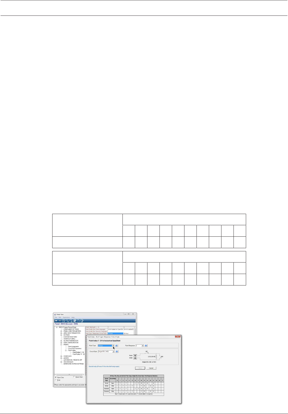
Control Panel Points | en 179
Bosch Security Systems, Inc. Program Entry Guide 2017.03 | 03 | F.01U.323.389
– Point Index 13, 28: Interior Follower
– Point Index 14: Keyswitch Maintained
– Point Index 15: Keyswitch Momentary
– Point Index 16: Open/Close Point
– Point Index 17, 18: Gas Point
– Point Index 19: AUX AC Supervision
Selections: (click the links below for a description of each point index)
–24-Hour, page 197
–Part On, page 197
–Interior, page 198
–Interior Follower, page 199
–Keyswitch Maintained, page 199
–Keyswith Momentary, page 199
–Open / Close Point, page 200
–Fire Point, page 200
–Aux AC Supervision, page 200
–Gas Point, page 200
–Custom Function, page 200
This parameter defines the point type.
RPS Menu Location
Points > Point Indexes > Point Type / Response / Circuit Style
10.3.5 Point Response
Default:
Point Profile
12345678910
Point Response Default 0111190890
Point Profile
11 12 13 14 15 16 17 18 19 20
Point Response Default 8981111900
Selections:0 – 9, A – F
The combined Point Type / Response / Circuit Style parameter allows you to configure all
three parameters in a single window.
Figure10.1: Point type-response-circuit style window
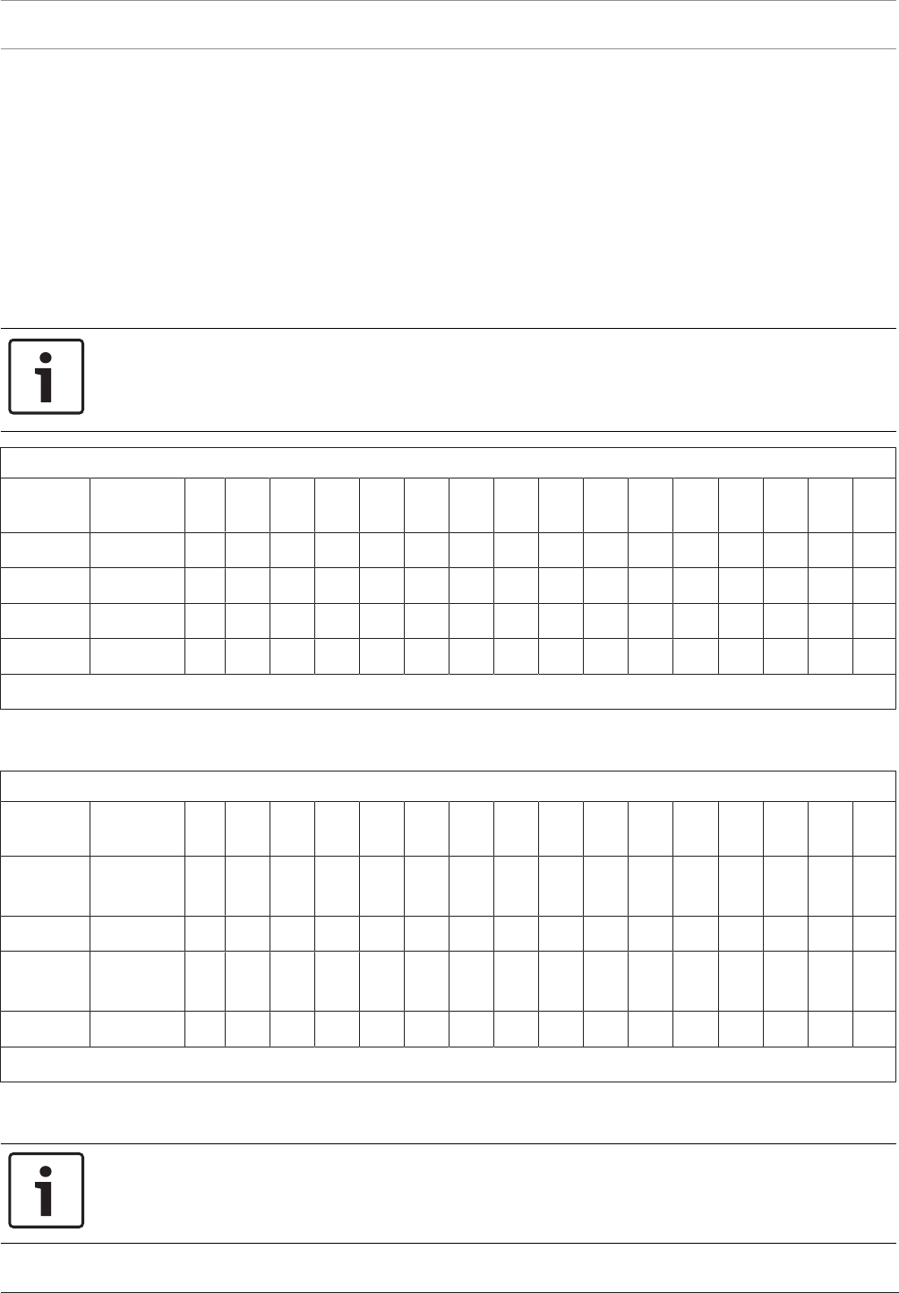
180 en | Points Control Panel
2017.03 | 03 | F.01U.323.389 Program Entry Guide Bosch Security Systems, Inc.
The Point Response parameter in combination with the Point Type parameter determines how
the control panel responds to changes on point sensor loops (open, short, normal) for wired
points, or changes in point states for wireless point devices (fault, normal, trouble).
The tables below show the Point Response selections for:
– 24 Hour, Fire, Gas, and AUX AC Supervision
– Controlled point types – Part On, Interior, and Interior Follower
– Keyswitch Maintained
– Keyswitch Momentary
– Open/Close Point
– Custom Function
Notice!
Changing Point Type automatically changes Point Response to default
Selecting a Point Type automatically changes the Point Response to the default for that Point
Type.
24 Hour, Fire, Gas, and AUX AC Point Types, Single EOL Circuit Style, Point Response Selections
Armed
State
Circuit
State 0 1 2 3 4 5 6 7 8 9 A B C D E F
Armed Open I T I T I T S T S S
Armed Short I I T T I T T S S S
Disarmed Open I T I T I T S T S S
Disarmed Short I I T T I T T S S S
Key: I = instant alarm, S = supervisory alarm, T = trouble, blank = no response
Example: Point Type = 24-hour and Point Response = 8. 24-hour point with supervisory
response when open and a trouble response when shorted.
24 Hour, Fire, and Gas Point Types, Dual EOL Circuit Style, Point Response Selections
Armed
State
Circuit
State 0 1 2 3 4 5 6 7 8 9 A B C D E F
Armed Open/
Short
T I T I
Armed Fault I I S S
Disarmed Open/
Short
T I T I
Disarmed Fault I I S S
Key: I = instant alarm, S = supervisory alarm, T = trouble, blank = no response
Example: Point Type = 24-hour and Point Response = 2. 24-hour point with supervisory
response for fault and a trouble response for open or short.
Notice!
For Dual EOL Circuit Style, purchase second 1kΩ EOL separately
Order ICP-1K22AWG-10, package of 10 resistors.

Control Panel Points | en 181
Bosch Security Systems, Inc. Program Entry Guide 2017.03 | 03 | F.01U.323.389
Notice!
Control panel and B208 Octo-input firmware requirements for Dual EOL
To use the Dual EOL Circuit style, verify the control panel firmware is v3.01 or greater.
If you are using a B208 Octo-input Module, verify the module firmware is v2.1.1 or greater.
24 Hour, Fire, and Gas Point Types, No EOL Circuit Style, Point Response Selections
Armed
State
Circuit
State 0 1 2 3 4 5 6 7 8 9 A B C D E F
Armed Fault I T S
Disarmed Fault I T S
Key: I = instant alarm, S = supervisory alarm, T = trouble, blank = no response
Example: Point Type = 24-hour and Point Response = 2. 24-hour point with supervisory
response for fault and a trouble response for open or short.
Controlled Point Types, Single EOL Circuit Style, Point Response Selections
Armed
State
Circuit
State 0 1 2 3 4 5 6 7 8 9 A B C D E F
Armed Open I I I I D D I I D I I I I I T
Armed Short I I I I I I D D D I I I I I I
Disarmed Open T T T I I T I T
Disarmed Short T T T I T I I
Key: I = instant alarm, D = delayed alarm, T = trouble, blank = no response
Example: Point Type = Part On and Point Response = 8. Perimeter point with delayed alarm
response when armed (opened or shorted) and no response when disarmed.
Controlled Point Types, Dual EOL Circuit Style, Point Response Selections
Armed
State
Circuit
State 0 1 2 3 4 5 6 7 8 9 A B C D E F
Armed Open/
Short
IIIIIIII
Armed Fault I D I D I D I D
Disarmed Open/
Short
T T I I T T I I
Disarmed Fault T T T T
Key: I = instant alarm, D = delayed alarm, T = trouble, blank = no response
Example: Point Type = Part On and Point Response = 1. When the area is on (armed), a fault
on the point circuit creates a delayed alarm response. An open or short on the point circuit
creates an instant alarm.
When the area is off (disarmed), an open or short on the point circuit creates a point trouble.
There is no response for a fault on the point circuit.

182 en | Points Control Panel
2017.03 | 03 | F.01U.323.389 Program Entry Guide Bosch Security Systems, Inc.
Notice!
For Dual EOL Circuit Style, purchase second 1kΩ EOL separately
Order ICP-1K22AWG-10, package of 10 resistors.
Notice!
Control panel and B208 Octo-input firmware requirements for Dual EOL
To use the Dual EOL Circuit style, verify the control panel firmware is v3.01 or greater.
If you are using a B208 Octo-input Module, verify the module firmware is v2.1.1 or greater.
Controlled Point Types, No EOL Circuit Style, Point Response Selections
Armed
State
Circuit
State 0 1 2 3 4 5 6 7 8 9 A B C D E F
Armed Fault I I D D T
Disarmed Fault T T T
Key: I = instant alarm, D = delayed alarm, T = trouble, blank = no response
Example: Point Type = Part On and Point Response = 2. When the area is on (armed), a fault
on the point circuit creates a delayed alarm response.
When the area is off (disarmed), there is no response for a fault on the point circuit.
Keyswitch Maintained Point Type, Point Response Selections
Armed
State
Circuit
State 0 1 2 3 4 5 6 7 8 9 A B C D E F
Armed Open D
Armed Short I I
Disarmed Open A
Disarmed Short T T
Key: A = transition from normal to open changes arming state to armed, D = transition from normal to open
changes arming state to disarmed, I = instant alarm, T = trouble, blank = no response
When the point response is set to 1 and the point circuit is normal, the area is off (armed
state is disarmed). Changing the point circuit state from normal to open turns the area on
(armed state is armed). Changing the point circuit state from open to normal turns the area
off (armed state is disarmed).
When the point response is set to 2 and the point circuit is normal, the area is on (armed state
is armed). Changing the point circuit state from normal to open turns the area off (armed
state is disarmarmed). Changing the point circuit state from open to normal turns the area on
(armed state is armed).
A short on the point circuit creates a point trouble while the area is off (disarmed). A short on
the point circuit while the area is on (armed) creates an instant alarm. When the point circuit
returns to normal or open the trouble restores.
Keyswitch Momentary Point Type, Point Response Selections
Armed
State
Circuit
State 0 1 2 3 4 5 6 7 8 9 A B C D E F
Armed Open I

Control Panel Points | en 183
Bosch Security Systems, Inc. Program Entry Guide 2017.03 | 03 | F.01U.323.389
Keyswitch Momentary Point Type, Point Response Selections
Armed
State
Circuit
State 0 1 2 3 4 5 6 7 8 9 A B C D E F
Armed Short D
Disarmed Open T
Disarmed Short A
Key: A = transition from normal to short to normal changes arming state to armed, D = transition from normal to
short to normal changes arming state to disarmed, I = instant alarm, T = trouble, blank = no response
The point response is fixed to 1 for the Keyswitch Momentary Point type. Changing the point
circuit state from normal to short to normal, toggles the armed state of the area. If the area is
on (armed) it is turned off (disarmed). If the area is off (disarmed) it is turned on (armed).
An open on the point circuit creates a point trouble while the area is off (disarmed). An open
on the point circuit while the area is on (armed) creates an instant alarm. When the point
circuit returns from open to normal the trouble restores.
Open/Close Point Type, Point Response Selections
Armed
State
Circuit
State 0 1 2 3 4 5 6 7 8 9 A B C D E F
Armed Open I
Armed Short D
Disarmed Open T
Disarmed Short D
Key: D = transition from normal to short changes point arming state to disarmed (point arming state is armed
when point circuit state is normal), I = instant alarm, T = trouble, blank = no response
The point response is fixed to 1 for the Open/Close Point type.
Changing the point circuit state to normal arms the point. The control panel sends a point
closing report. Changing the circuit state from normal to open creates an instant point alarm.
Changing the point circuit state to short disarms the point. The control panel sends a point
closing report. Changing the circuit state from short to open creates a point trouble.
Custom Function Point Type, Single EOL Circuit Style, Point Response Selections
Armed
State
Circuit
State 0 1 2 3 4 5 6 7 8 9 A B C D E F
Armed Open CF CF T CF CF CF T CF
Armed Short CF CF CF T CF CF CF T
Disarmed Open CF CF T CF CF CF T CF
Disarmed Short CF CF CF T CF CF CF T
Key: CF = control panel executes custom function on transition to circuit state. T = trouble, blank = no response
When the point circuit state changes the control panel responds by activating a custom
function.
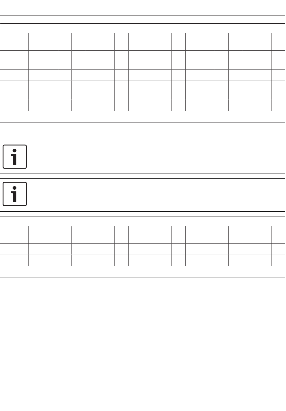
184 en | Points Control Panel
2017.03 | 03 | F.01U.323.389 Program Entry Guide Bosch Security Systems, Inc.
Custom Function Point Type, Dual EOL Circuit Style, Point Response Selections
Armed
State
Circuit
State 0 1 2 3 4 5 6 7 8 9 A B C D E F
Armed Open/
Short
TTTTTTTTTT
Armed Fault T CF CF CF CF CF CF CF CF CF CF CF T
Disarmed Open/
Short
TTTTTTTTTT
Disarmed Fault CF T CF CF CF CF T CF CF CF CF CF T
Key: CF = control panel executes custom function on transition to circuit state. T = trouble, blank = no response
When the point circuit state changes the control panel responds by activating a custom
function.
Notice!
For Dual EOL Circuit Style, purchase second 1kΩ EOL separately
Order ICP-1K22AWG-10, package of 10 resistors.
Notice!
Control panel and B208 Octo-input firmware requirements for Dual EOL
To use the Dual EOL Circuit style, verify the control panel firmware is v3.01 or greater.
If you are using a B208 Octo-input Module, verify the module firmware is v2.1.1 or greater.
Custom Function Point Type, No EOL Circuit Style, Point Response Selections
Armed
State
Circuit
State 0 1 2 3 4 5 6 7 8 9 A B C D E F
Armed Fault T CF CF CF CF CF CF CF CF CF CF CF T B
Disarmed Fault CF T CF CF CF CF CF CF CF CF CF CF T B
Key: CF = control panel executes custom function on transition to circuit state. T = trouble, blank = no response
When the point circuit state changes the control panel responds by activating a custom
function.
Point Response for B820 SDI2 Inovonics Interface Module
When point Source is set to Wireless and a B820 SDI2 Inovonics Interface Module is used,
wireless points:
– send Short for point fault (regardless of sensor loop open/short state)
– send Open for a tamper event (enclosure cover removed)
Point Response for B810 RADION receiver SD
When point Source is set to wireless and a B810 RADION receiver SD module is used, wireless
points:
– send Open or Short for point fault (the electrical state of the sensor loop)
– send Short for the reed switch (magnet not present)
– send Tamper for a tamper event (enclosure cover removed)
RPS Menu Location
Points > Point Indexes > Point Type / Response / Circuit Style
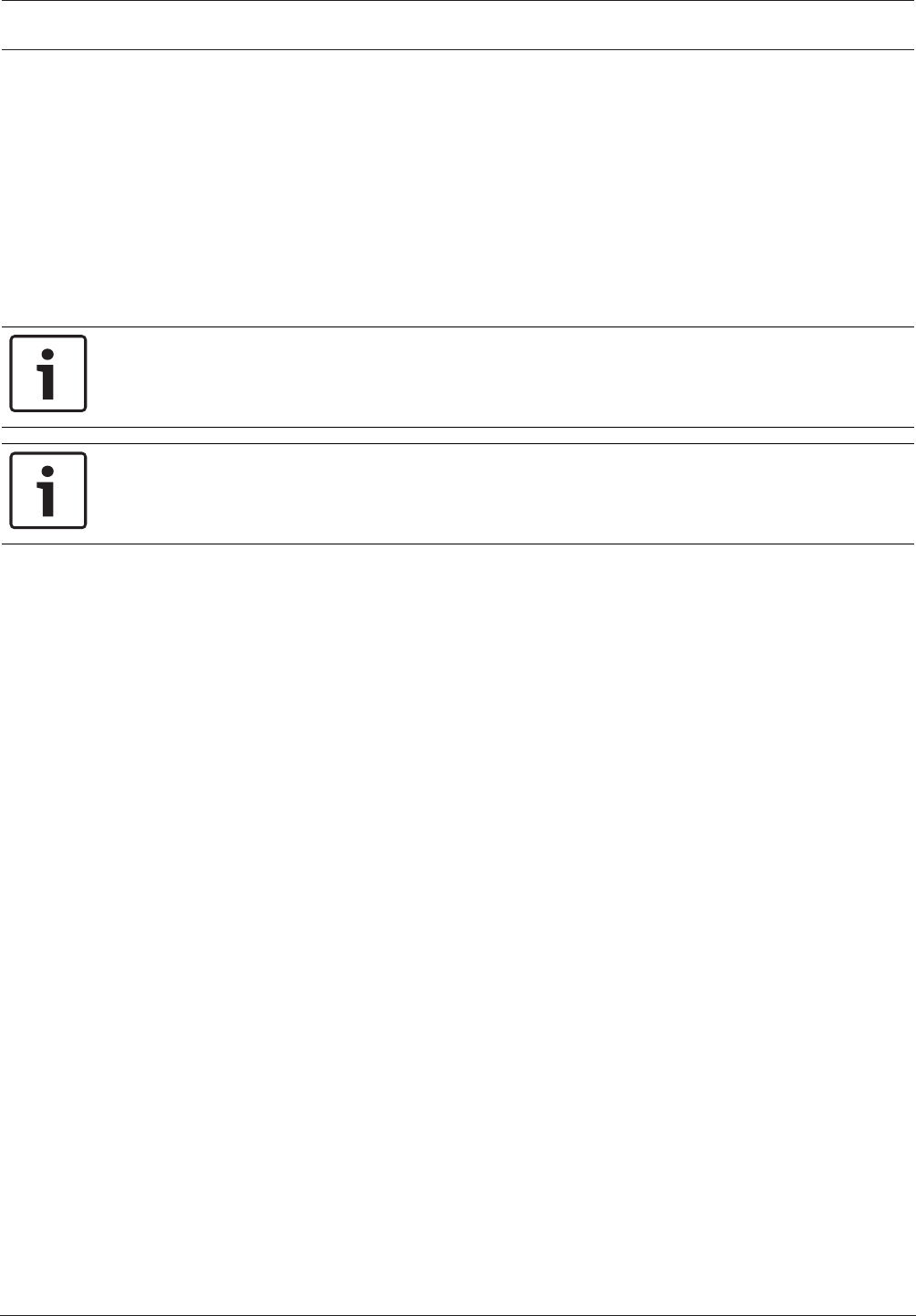
Control Panel Points | en 185
Bosch Security Systems, Inc. Program Entry Guide 2017.03 | 03 | F.01U.323.389
Further information
Point Type, page 178
Circuit Style, page 196
10.3.6 Entry Delay
Default: 30 seconds
Selections:5 - 600 seconds (5-second increments)
This parameter sets the amount of entry delay time that a user has after faulting a controlled
point (Part On, Interior or Interior Follower) with a delayed response (D) (Point Response,
page 179) of 4, 5, 6, 7, or 8.
Notice!
To comply with UL standards, the total amount of time entered in Entry Delay and Alarm
Abort, page 194 must not exceed 1 minute.
Notice!
To comply with SIA CP-01 False Alarm Reduction, set this parameter between 30 and 240
seconds for all point indexes. Refer to SIA CP-01 Verification for more information.
On the keypad's display, DISARM NOW appears for the duration of the time programmed
when the point is faulted in the delay event. The keypad display alternates between DISARM
NOW and the point text of the point that caused the area to enter into Entry Delay.
If this time is allowed to expire before disarming or if the point is faulted to an instant
response (I) an alarm occurs.
Make entries in five-second increments. The programmer does not allow off-increment entries.
Disarm by Passcode, page 166 activates when the last digit of the passcode is pressed. The
[ENTER] key is allowed, but not required, when entering a passcode during Entry Delay.
If a subsequent perimeter or interior follower delay point trips while the area is already in
entry delay, the control panel adjusts the delay time to the delay point with the least amount
of delay time.
When a user enters an area, a perimeter point is faulted and Entry Delay starts. If an interior
point must fault during Entry Delay to allow the user to disarm the area at a keypad, program
Point Type, page 178 as Interior Follower.
RPS Menu Location
Points > Point Indexes > Entry Delay
10.3.7 Entry Tone Off
Default: No (for all Point Indexes)
Selections:
– Yes. Disable entry delay tone when this point is faulted to the delay response.
– No. A tone sounds at keypads when this point initiates entry delay.
This parameter enables/disables the entry delay warning tone for this point.
Do not set this parameter to No on points used to notify the user to disarm the system. The
possibility of false alarms increases if the entry delay warning is not used.
Entry Tone can also be turned off when programming your Entry Tone, page 113 in the keypad
section which allows you to manage the tone by keypad.
You might want to disable the entry tone in high security applications where you do not want
to annunciate entry delay.

186 en | Points Control Panel
2017.03 | 03 | F.01U.323.389 Program Entry Guide Bosch Security Systems, Inc.
RPS Menu Location
Points > Point Indexes > Entry Tone Off
10.3.8 Silent Bell
Default:
– Point Index 2: Yes
– All other Point Indexes: No
Selections:
– Yes Activate the Silent Alarm, page 132 output when this point goes into alarm; Do not
activate the Alarm Bell output or keypad alarm sounders. This setting only applies to non-
fire/gas points.
– No Activate the Fire Bell, page 129, Gas Bell, page 133 or Alarm Bell, page 129 output and
sound the alarm tone at keypads when this point goes into alarm. If this is a fire point, it
activates the Fire Bell. If this is a gas point, it activates the Gas Bell, otherwise, it
activates the Alarm Bell. The amount of time and pattern of the output activation is
programmed by area.
This parameter determines whether the bell and keypad sounders activate upon an alarm
event for non-fire/gas points. Fire and Gas points ignore this parameter setting and always
activate the bell and sound the alarm tone at keypads when this point goes into alarm.
If you want this point to eventually ring the bell because the message failed to reach the
central station receiver, set Audible After Two Fails, page 186 to Yes.
RPS Menu Location
Points > Point Indexes > Silent Bell
10.3.9 Ring Until Restored
Default: No (for all Point Indexes)
Selections:Yes/No
– Yes Fire or Gas Bell output and keypad sounders for this point cannot be deactivated,
from a keypad or upon bell time-out, until the point is restored to normal.
– No Fire or Gas Bell output and keypad alarm sounders for this point can be deactivated,
either from a keypad or upon bell time-out, whether or not the point has been restored to
normal.
Use this parameter for fire or gas applications to meet the requirement that audible alarms
cannot be silenced until the fault event clears.
If the point restores and the originating alarm is not silenced from the keypad, the alarm
output continues until Fire Bell or Gas Bell time expires. If the point does not restore, the
alarm output continues even after bell time expires.
RPS Menu Location
Points > Point Indexes > Ring Until Restored
10.3.10 Audible After Two Fails
Default: No (for all Point Indexes)
Selections:
– Yes For silent points, Alarm Bell, page 129 output activates after two failed attempts to
send the report to the central station.
– No Silent Bell, page 186 points do not cause the Alarm Bell output to activate even if the
report does not get to the central station receiver.
When set to Yes, if the report fails to reach the central station after two attempts, a silent
alarm rings the alarm bell. A silent alarm is generated when a point with Silent Bell set to Yes
is alarmed.

Control Panel Points | en 187
Bosch Security Systems, Inc. Program Entry Guide 2017.03 | 03 | F.01U.323.389
When a point programmed for Silent Bell, page 186 is faulted, Burg Time, page 98 starts even
though the bell is not yet ringing. It could take up to three minutes before the second attempt
has failed. Because of this, ensure Burg Time is set to provide the amount of bell time you
would like, minus the three minutes it might take before the bell actually begins to ring.
RPS Menu Location
Points > Point Indexes > Audible After 2 Fails
10.3.11 Invisible Point
Default:
– Point Index 2: Yes
– All other Point Indexes: No
Selections:
– Yes Keypads do not display alarm activity from this point.
– No Activity from this point is visible at the keypads.
This parameter determines whether the point appears in the keypad display upon an alarm
event. Point text appears and annunciation is made for invisible points that are programmed
for a trouble event in point response.
To prevent the keypad alarm tone and the Alarm Bell, page 129 from sounding, this point must
have Silent Bell, page 186 set to Yes.
Note: Fire and Gas points always function as if this parameter is set to No.
RPS Menu Location
Points > Point Indexes > Invisible Point
10.3.12 Buzz on Fault
Default:
– Point Index 9: 1
– All other Point Indexes: 0
Selections:0 to 3
This parameter brings attention to a faulted point by generating a trouble buzz even if the
point is not actually in trouble.
Instant Alarm (I), Trouble (T) and Supervisory (S) point responses take priority over Buzz on
Fault. If the point response is "blank", then Buzz on Fault can be the only response. Refer to
the Point Response, page 179 configuration for a description of response types for each point
type and how they are affected by arm state.
If an alarm, trouble or supervisory event occurs and is silenced, then Buzz on Fault selections
1 and 3 will persist until the point returns to normal.
Refer to the following table for Buzz on Fault controlled point operation and 24-hour point
operation:
Selection Buzz on fault Silence while
faulted
Silence after
restore
Description
0 Disabled Does not apply Does not apply Buzz on Fault
feature is
disabled.
1 Yes Not allowed Allowed Buzz persists
until the point
restores and is
silenced.
188 en | Points Control Panel
2017.03 | 03 | F.01U.323.389 Program Entry Guide Bosch Security Systems, Inc.
Selection Buzz on fault Silence while
faulted
Silence after
restore
Description
2 Yes Allowed Allowed Buzz can be
silenced.
3 Yes Not allowed Auto silence Buzz persists
until the point
restores.
Notice!
Custom Function point types do not support Buzz on Fault.
RPS Menu Location
Points > Point Indexes > Buzz on Fault
10.3.13 Watch Point
Default:
– Point Indexes 7 to 8: Yes
– All other Point Indexes: No
Selections:
– Yes:This point activates Watch Mode responses if it is faulted when the control panel is
in Watch Mode.
– No:Do not activate Watch Mode responses for this point.
This parameter allows a controlled point to generate a watch tone as long as the area is
disarmed and not being faulted into a trouble or alarm event.
Notice!
You can only hear the watch tone on a keypad where the current area is the point’s assigned
area.
You can only hear the watch tone on a keypad where the current area is the point’s assigned
area.
RPS Menu Location
Points > Point Indexes > Watch Point
10.3.14 Output Response Type
Default: 0
Selections:
– 0- Point state does not affect the operation of the corresponding output.
– 1- The output corresponding with this point activates when the point is faulted to any off
normal state, even if the point is bypassed. The output automatically resets when the
point is returned to normal.
– 2- The output corresponding with this point latches when the point goes into an alarm
condition. This output remains on steady output until the alarm is cleared from the
keypad display.
This parameter causes an output to respond when a corresponding point with the same
number is faulted.

Control Panel Points | en 189
Bosch Security Systems, Inc. Program Entry Guide 2017.03 | 03 | F.01U.323.389
Outputs used for this function must not be shared with any other point, keypad, sked, area, or
panel output functions. Sharing can cause errors in output operation.
RPS Menu Location
Points > Point Indexes > Output Response Type
10.3.15 Display as Device
Default:No
Selections:
– Yes. Display [CHECK DEVICE] when this point is off normal.
– No. Do not display [CHECK DEVICE] when this point is off normal.
Use this parameter to cause the to display CHECK DEVICE once a point is off normal or is
acknowledged after going into alarm.
This parameter can be used for devices that have a dry contact output which faults a point
once the device is in a trouble event.
RPS Menu Location
Points > Point Indexes > Display as Device
10.3.16 Local While Disarmed
Default:
– Point Index 9, 12: Yes
– All other Point Indexes: No
Selections:
– Yes. Suppress alarm, trouble and restoral reports from this point while the area it is
assigned to is disarmed.
– No. Report events occurring from this point while the area is disarmed.
Use this parameter to allow a controlled point to report alarms, troubles and restoral reports
only when the area is armed.
Notice!
A restoral report is transmitted even when the area is disarmed if the alarm or trouble event
occurred while the area was armed and returned to normal after the area was disarmed.
This parameter suppresses all reports from 24-hour points. Do not use this parameter with
Point Type set to 24-Hour. This parameter only works for disarmed points, and a 24 hour
"always armed" point. Instead, choose any type other than 24-Hour, and use a point response
that sends an alarm whether the point is armed or not. For instance, Point Type, page 178 Part
On and Point Response 9 send an alarm on a trouble or a short (I) whether the area is armed
or not.
This parameter affects keyswitch points and suppresses keyswitch (troubles/restorals).
This parameter does not affect local annunciation.
RPS Menu Location
Points > Point Indexes > Local While Disarmed
10.3.17 Local While Armed
Default: No
Selections:Yes/No
– Yes Suppress alarm, trouble and restoral reports from this point while the area it is
assigned to is armed.

190 en | Points Control Panel
2017.03 | 03 | F.01U.323.389 Program Entry Guide Bosch Security Systems, Inc.
– No Report events occurring from this point while the area is armed.
Use this parameter to allow a controlled point (Part On, Interior and Interior Follower), to
report alarms, troubles and restoral reports only when the area is disarmed. This parameter
does not affect local annunciation.
This parameter suppresses all reports from 24-hour points. This parameter only works for
disarmed points, and a a 24 hour "always armed" point. Instead, choose any typeother than
24-Hour, and use a point response that sends an alarm whether the pointis armed or not. For
instance, Point Type Part On and Point Response 9 send an alarm on a trouble or a short (I)
whether the area is disarmed or not.
This parameter affects keyswitch points and suppresses keyswitch (alarms/troubles/restorals)
and D279 (opening/closing/troubles/restorals) Do not use this parameter for controlled points
that arm/disarm.
RPS Menu Location
Points > Point Indexes > Local While Armed
10.3.18 Disable Restorals
Default: No
Selections:Yes/No
– Yes Disable restoral reports for this point.
– No Enable restoral reports for this point.
Use this parameter to disable any restoral reports from this point after it returns to normal
from an alarm or trouble event.
RPS Menu Location
Points > Point Indexes > Disable Restorals
10.3.19 Force Arm Returnable
Default: No
Selections:
– Yes This point automatically returns to the system when it restores to normal.
– No This point stays out of the system until the area is disarmed.
Use this parameter to allow points which were force armed out of the area to return back to
the armed state once they are normal again without needing to disarm the system.
Use this parameter on points assigned to loading dock doors that are required to be left open
until loading is completed. Once the loading dock door is closed, it detects an opening and
sends an alarm.
RPS Menu Location
Points > Point Indexes > Force Arm Returnable
10.3.20 Bypass Returnable
Default: No
Selections:
– Yes This point automatically returns to the system when the area is disarmed.
– No This point stays out of the system through arming and disarming cycles.
Use this parameter to return a point which has been bypassed, force armed or swinger
bypassed back into the system once the area this point is assigned to is disarmed.
Set this parameter to No for interlock points.
When not allowed to return to the system through disarming, the point must be manually
unbypassed using the UNBYPASS?, keypad function, Sked functions Unbypass a Point, or
Unbypass All Points, or remotely using RPS. For force armed points to remain bypassed,
ensure Force Arm Returnable, page 190 is set to No.

Control Panel Points | en 191
Bosch Security Systems, Inc. Program Entry Guide 2017.03 | 03 | F.01U.323.389
RPS Menu Location
Points > Point Indexes > Bypass Returnable
10.3.21 Bypassable
Default:
– Point Profiles 1 to 7-13, 20: Yes
– Point Profiles 2-6, 14-19: No
Selections:
– Yes. This point can be bypassed and force armed.
– No. This point can not be bypassed or force armed from the keypad or RPS. However, it
can be force armed by automatic arming at the end of the closing window (Refer to Auto
Close ), or by a Sked programmed to arm the area.
Use this parameter to allow this point to be bypassed and/or force armed.
When a 24-hour point or 24-hour supervisory point is bypassed, 24 HOUR BYPASS
continuously scrolls on the keypad. FIRE BYPASS scrolls to indicate a 24-hour fire point or a
fire supervisory point is bypassed. GAS BYPASS scrolls to indicate a gas detector or gas
supervisory point is bypassed.
To have the alarm capability of a 24-hour point without the continuous scrolling, use a
perimeter point with a Point Response, page 179 of 9 to E.
Setting this parameter to Yes for Cross Point Timer, page 176 can cause missed cross-point
alarms. For example, if Points 1 and 2 are programmed as Cross Points and Point 1 is
bypassed or force armed, Point 2 is not able to generate an ALARM CROSS POINT event.
However, Point 2 can generate an UNVERIFIED or ALARM event depending on how the point
was tripped.
A point can be bypassed at the keypad using the BYPASS? function.
RPS Menu Location
Points > Point Profiles > Bypassable
10.3.22 Swinger Bypass
Default: No
Selections:
– YesEnable Swinger Bypass for this point.
– NoDisable Swinger Bypass for this point.
Use this parameter to allow the control panel to automatically bypass a point that erroneously
reports a pre-determined number of alarm or trouble events within the same arm cycle.
The control panel reports a Swinger Bypass when the Swinger Bypass Count, page 79 is
reached and Report Bypass at Occurrence, page 191 is set to Yes. If the point has a partial
count (less than the Swinger Bypass Count number of events an hour), the count is reset to
zero.
Bypassable, page 191 does not need to be set to Yes for swinger bypass to work.
A swinger-shunted point returns to the system if Bypass Returnable, page 190 is set to Yes. If
not, return the point to the system as described in Bypass Returnable.
RPS Menu Location
Points > Point Indexes > Swinger Bypass
10.3.23 Report Bypass at Occurrence
Default: No
Selections:
– Yes:Send a report at the time that the point is bypassed.
– No:Do not send a report at the time the point is bypassed.

192 en | Points Control Panel
2017.03 | 03 | F.01U.323.389 Program Entry Guide Bosch Security Systems, Inc.
This parameter allows a point to generate a COMMAND BYPASS report as soon as a user
bypasses the point from the keypad.
Enable this parameter for all bypassable 24-hour points. You can also report a bypassed point
at the time the area is armed. Refer to Defer Bypass Report, page 192.
RPS Menu Location
Points > Point Indexes > Report Bypass at Occurrence
10.3.24 Defer Bypass Report
Default: No
Selections:
– Yes.Send a report with the closing report instead of when the point is bypassed by a
user.
– No.Do not defer bypass reports.
Use this parameter to prevent points that are bypassed by the user from reporting until the
area is armed.
Once the area is armed, the bypassed points as well as any point being bypassed during the
arming sequence report as POINT BYPASS along with the closing report.
To report the bypass at occurrence and when the area is armed, set this parameter and Report
Bypass at Occurrence, page 191 to Yes. A COMMAND BYPASS report is sent as soon as it
occurs, and a POINT BYPASS report is sent with the closing report.
Bypass reports do not occur when arming the area if the closing report is suppressed by
Open/Close windows, or are not being reported.
Bypass reports for 24 hour points are not sent if this parameter and Report Bypass at
Occurrence, page 191 are both set to No.
RPS Menu Location
Points > Point Indexes > Defer Bypass Report
10.3.25 Cross Point
Default: No
Selections:
– Yes Enable cross point alarm events.
– No Disable cross point alarm events.
This parameter reduces false alarms. Points can be programmed so that the control panel
needs two faults within a programmed period of time from at least two points within a cross
point group before creating cross point alarm events.
The Cross Point function is fixed to a minimum of two points per group.
Only use this parameter with Part On, Interior or 24-hour point types with instant alarm
response.
Each cross point group consists of eight points, and is identified by the point numbers in them
(for example, Cross Points 1-8, Cross Points 9-16, and so on. A minimum of two points must
be programmed to meet the cross point criteria.
Point numbers from different cross point groups do not affect each other.
When a point with this parameter set to Yes detects an alarm, the control panel starts the
cross point timer. If a second cross point in the same cross point group detects an alarm while
the cross point timer is active, the control panel sends cross point alarm events for both
points.
A cross point is considered to be in alarm when it meets the criteria for instant alarm
response. The cross point index must have Point Responses set to generate an instant alarm.
If a single cross point detects an alarm and stays faulted throughout the cross point timer, the
system sends a standard alarm report for that point.

Control Panel Points | en 193
Bosch Security Systems, Inc. Program Entry Guide 2017.03 | 03 | F.01U.323.389
If a single cross point detects an alarm, then restores, and does not detect any other event,
the system sends an unverified event for that point. A second alarm on the first point does not
create an alarm event, but rather an unverified event.
The cross point function applies only to alarm events. It does not apply to supervisory or
trouble events.
If an abort window delay is needed for the cross zone alarm, all cross points in the group must
have Alarm Abort set to Yes. It is recommended that all points in cross zone group use the
same point index.
RPS Menu Location
Points > Point Indexes > Cross Point
Additional resources
Point Response, page 179
Cross Point Timer, page 176
Alarm Abort, page 194
10.3.26 Alarm Verify
Default:
– Point Index 5: Yes
– All other Point Indexes: No
Selections:
– YesEnable alarm verification on this point.
– NoDisable alarm verification on this point.
Use this parameter only with fire points to designate them for alarm verification.
When an alarm verification point goes into alarm, the control panel removes power to all
resettable points for the duration programmed in Restart Time. If the point (or another
resettable point in the area) is still in alarm, or goes back into alarm within 65 seconds after
the initial verification time reset, an alarm is generated.
Alarm verification points must be programmed as Resettable.
During a Fire Walk Test, the reset time is 5 seconds. The time programmed in Restart Time is
ignored.
RPS Menu Location
Points > Point Indexes > Alarm Verify
Additional resources
Restart Time, page 92
Resettable, page 193
10.3.27 Resettable
Default:
Point Profiles 1-3, 6-20: No
Point Profiles 4,5: Yes
Selections:
– Yes This point is reset by the RESET SENSORS? function and during the alarm
verification sequence.
– No This point is not resettable.
Use this parameter if this is a powered point that requires interruption of power to reset a
latched alarm event. The resettable point function is typically used with smoke detectors and
glass break detectors.

194 en | Points Control Panel
2017.03 | 03 | F.01U.323.389 Program Entry Guide Bosch Security Systems, Inc.
When a sensor reset is initiated, the control panel does not accept alarms from any points in
which this parameter is set to Yes. During the five-second reset time, alarms from these points
are ignored. When initiated either through a walk test or the keypad function RESET
SENSOR?, or by RPS, power is interrupted to the device for 5 seconds. SENSOR RESET is
reported to the central station receiver.
Do not mix fire and intrusion devices on the same powered loop.
RPS Menu Location
Points > Point Indexes > Resettable
10.3.28 Alarm Abort
Default:
– Point Profiles 1, 7-10, 11-16, 20: Yes
– Point Profiles 2-6, 17-19: No
Selections:
– Yes If the point goes into alarm, the system delays the alarm report for the amount of
time specified in Abort Window.
– No If the point goes into alarm, the system immediately sends the alarm report.
This parameter allows points with the associated point index to delay a burglar alarm (non-
fire) event for the time period specified in Abort Window, page 77.
Notice!
To comply with UL standards, the total amount of time entered in Entry Delay, page 185 and
Alarm Event Abort must not exceed 1 minute.
An alarm is aborted by performing an alarm silence operation before this time elapses at a
keypad showing the burglar alarm event. When an alarm is successfully aborted, the keypad
shows an optional ALARM NOT SENT message. Refer to Abort Display, page 115 for more
information.
This parameter does not apply to fire alarms or invisible point alarms. When upgrading a non-
control panel account to a control panel account, RPS forces the default to No.
RPS Menu Location
Points > Point Indexes > Alarm Abort
10.3.29 Wireless Point Supervision Time
Default:
– Point Index 1-2, 7-16: 24 Hours
– Point Indexes 3-6: 4 Hours
Selections:
– None. Disable wireless point supervision.
– 4, 12, 24, 48, 72.Set the length of time in hours for wireless point supervision.
This parameter sets the length of time in hours between failure events to hear from the
wireless transmitter before sending a missing event for devices configured to report to the
Wireless Receiver.
RADION keyfobs will follow the supervision rules if configured as a point device. Fire points
have a fixed supervision interval of 4 hours, regardless of Wireless Point Supervision Time
setting. If the point type is Fire, then the Wireless Point Supervision Time setting can only be
set to 4 hours.
This is an alternate supervision interval to the global System (Repeater) Supervision Time, page
245 setting.

Control Panel Points | en 195
Bosch Security Systems, Inc. Program Entry Guide 2017.03 | 03 | F.01U.323.389
RPS Menu Location
Points > Point Indexes > Wireless Point Supervision Time
10.3.30 Custom Function
Default: Disabled
This specifies the custom function to be run when a point with this index faults to a short (S)
or open (O) state.
RPS Menu Location
Points > Point Indexes > Custom Function
10.3.31 Monitor Delay
Default: 00:00
Selections: 00:00, 00:01 thru 60:00
00:00 = disabled
Use this parameter to configure the length of time (MM:SS) a disarmed control panel waits
after a point faults before reporting the event to the central station.
The control panel sends a Burg Supervisory report to the central station if the point remains
faulted during the entire period of time configured in this parameter. If the point is restored
during this time, no report is sent. The control panel does not indicate monitor delay at the
keypad.
Enable this feature to monitor a door, such as a trash compactor, jewelry case, or freezer that
should not be left open.
Notice!
Starting a walk test that includes controlled points, or arming the points' area will cancel the
monitor point timer. No report is sent after the configured time expires.
RPS Menu Location
Points > Point Indexes (point profiles) > Monitor Delay
10.3.32 Delay Response, Disarmed
Default: 00:00
Selections: 00:05 thru 60:00
00:00 = disabled
This parameter sets the length of time (MM:SS) the control panel waits after a disarmed point
faults before annunciating or reporting the fault. This parameter only applies to the following
point types when armed:
–Part On, page 197
–Interior, page 198
–Interior Follower, page 199
Use this feature to delay the effect of the following parameters:
–Point Response, page 179
– Instant Alarm
– Supervisory
–Buzz on Fault, page 187
–Watch Point, page 188
–Output Response Type, page 188
–Display as Device, page 189
–Output, page 173
196 en | Points Control Panel
2017.03 | 03 | F.01U.323.389 Program Entry Guide Bosch Security Systems, Inc.
Notice!
Point Response (D) Delay Alarm is not supported by Delay Response feature. So, when a
Delay Alarm results in an instant alarm, that alarm is not delayed by this feature.
RPS Menu Location
Points > Point Indexes (point profiles) > Delay Response Disarmed
10.3.33 Delay Response, Armed
Default: 00:00
Selections: 00:05 thru 60:00
00:00 = disabled
This parameter sets the length of time (MM:SS) the control panel waits after an armed point
faults before annunciating or reporting the fault. This parameter only applies to the following
point types when armed:
–24-Hour, page 197
–Part On, page 197
–Interior, page 198
–Interior Follower, page 199
Use this feature to delay the effect of the following parameters:
–Point Response, page 179
– Instant Alarm
– Supervisory
–Output Response Type, page 188
–Display as Device, page 189
–Output, page 173
Notice!
Point Response (D) Delay Alarm is not supported by Delay Response feature. So, when a
Delay Alarm results in an instant alarm, that alarm is not delayed by this feature.
RPS Menu Location
Points > Point Indexes (point profiles) > Delay Response Armed
10.3.34 Circuit Style
Default: Single EOL (1KΩ)
Selections:
– Single EOL (1KΩ)
– Single EOL (2KΩ)
– Dual EOL
– No EOL
This parameter sets the circuit style for a point index.
Notice!
Circuit Style control panel firmware requirements
The Circuit Style Parameter is not available for control panel firmware v2.xx.
The Dual EOL resistor configuration is available only for control panel firmwarev3.01 and
higher.
The Single EOK (2KΩ) selection is only for control panel firmware v3.03 and higher.
The No EOL selection is only for control panel firmware v3.03 and higher.

Control Panel Points | en 197
Bosch Security Systems, Inc. Program Entry Guide 2017.03 | 03 | F.01U.323.389
Single EOL (1KΩ) – valid with all point sources.
Single EOL (2KΩ), Dual EOL, No EOL – valid with On-board and B208 point sources.
RPS Menu Location
Points > Point Indexes (point profiles) > Point Type/Response/Circuit Style
Further information
Point Type, page 178
Point Response, page 179
10.3.35 Normal State
(Not available on version 2.xx control panels.)
Default: Open
Selections:
– Open – an open point circuit is the Normal state.
– Short – a short on point circuit is the Normal state.
This parameter sets the Normal state for the point index.
When this parameter is set to Open, an open circuit on the point sensor loop is the Normal
state.
When this parameter is set to Short, a shorted circuit on the point sensor loop is the Normal
state.
RPS Menu Location
Points > Point Profile (Point Index) > Point Type/Response/Circuit Style
10.4 Point Profile descriptions
10.4.1 24-Hour
A 24-hour point is not turned on and off from a keypad. 24-hour points are armed all the time,
and can be used for panic, medical, and police alerts.
24-hour points can be programmed as bypassable. However, the application should be
carefully considered before using the bypassable option. Bypassable 24-hour points should be
programmed to Buzz on Fault, page 187.
When a 24-hour point is bypassed, the report should be sent as it occurs. If the area contains
all 24-hour points, the area is never armed or disarmed; therefore, a deferred bypass report is
not sent.
24-hour protection for fire doors, roof hatches, etc. Instead of programming this type of
protection as a 24-hour point, consider using a perimeter point type with a Point Response,
page 179 of 9 to E. 24-hour points do not show faults when an arming function is entered, but
perimeter points do. When programming for this type of protection, you should consider using
the Buzz On Fault and Local While Disarmed, page 189 options.
Hold-up devices in UL installations: the 24-Hour point type must be used for points connected
to hold-up devices. The point text must include, “hold-up”.
10.4.2 Part On
Configuring a point profile with the Part On point type makes it a Part On point profile. Points
assigned to a Part On point profile are Point On points. Part On points are typically used to
monitor devices in the perimeter of the premises (doors and windows).
A Part On point profile includes a configurable entry delay time. Entry delay time provides time
for users to reach a keypad and turn the area Off without creating an alarm event. For
example, when a user opens the front door (tripping a Part On point) entry delay time begins.
The user needs to proceed to a keypad and turn the area off before exit delay time expires to
prevent an alarm event.

198 en | Points Control Panel
2017.03 | 03 | F.01U.323.389 Program Entry Guide Bosch Security Systems, Inc.
If the area is in entry delay and a second Part On point trips, the control panel compares the
remaining entry delay time to the entry delay time programmed for the second Part On point.
If the second point's entry delay time is less than the remaining time, it shortens the entry
delay time.
Notice!
Part On Points with instant Point Response create immediate alarm events
Perimeter Points programmed for an instant Point Response, page 179 do not start entry delay
time when tripped. They generate an alarm event immediately, even during entry or exit delay.
When a user turns an area All On; Part On points, Interior points, and Interior Follower points
are all armed.
When a user turns an area Part On only Part On points are armed. Interior points, and Interior
Follower points are not armed. In a typical system, turning an area Part On arms only the
perimeter protection allowing users to remain in the premises without creating alarm events
from interior points.
10.4.3 Interior
Configuring a point profile with the Interior point type makes it an Interior point profile. Points
assigned to an Interior point profile are Interior points. Interior points are typically used to
monitor interior detection devices such as interior doors, motion detectors, photoelectric
beams, or carpet mats.
Interior points are armed only when the area is All On. They are not armed when the area is
Part On.
The Point Response, page 179 for Interior points can be configured for instant or delayed alarm
response.
– Instant - points configured for instant alarm response create alarm events immediately,
even during entry or exit delay time. Interior points are commonly configured for instant
alarm response.
– Delayed - when an interior point configured for delayed alarm response is tripped while
the area is All On, it initiates entry delay time. It will not create an alarm event unless
entry delay time expires before the area is turned off.
If the area is already in entry delay when an interior point with delayed alarm response
trips, the control panel compares the remaining entry delay time to the entry delay time
programmed for the interior point. If the interior point's entry delay time is less than the
remaining time, it shortens the entry delay time
Delayed points can also initiate an entry tone at the keypad (Refer to Entry Tone Off, page
185).
Notice!
Use the Interior Follower, page 199 profile for instant alarm if the area is not in entry delay
For some installations you may want an interior point that follows, but can not initiate entry
day. Tripping an Interior Follower point while the area is All On creates an instant alarm
event. However, if another point is tripped starting entry delay, and then the Interior Follower
point is tripped, the Interior Follower point delays the alarm response until exit delay time
expires. If the area is turned Off before entry delay time expires there is no alarm response.
Control Panel Points | en 199
Bosch Security Systems, Inc. Program Entry Guide 2017.03 | 03 | F.01U.323.389
10.4.4 Interior Follower
Configuring a point profile with the Interior Follower point type makes it an Interior Follower
point profile. Points assigned to an Interior Follower point profile are Interior Follower points.
Interior Follower points are typically used to monitor interior detection devices such as
interior doors, motion detectors, photoelectric beams, or carpet mats.
Interior Follower points are armed only when the area is All On. They are not armed when the
area is Part On.
Interior Follower points follow, but can not initiate entry day. Tripping an Interior Follower
point while the area is All On creates an instant alarm response. However, if another point is
tripped starting entry delay, and then the Interior Follower point is tripped, the Interior
Follower point delays the alarm response until exit delay time expires. If the area is turned Off
before entry delay time expires there is no alarm response
During Exit Delay, faulting an Interior Follower point does not create an alarm event (even if a
Part On, Delay point is not faulted during the exit delay).
Interior Follower points do not initiate entry delay even when configured for a delayed alarm
response (Point Response, page 179 set to 4, 5, 6, 7, or 8).
Notice!
Use the Interior, page 198 profile and delayed alarm response for interior points that
initiate entry delay
For some installations you may want an interior point that can initiate entry day. Tripping an
Interior point configured for delayed alarm response (refer to Point Response, page 179) while
the area is All On initiates entry delay. The alarm response is delayed until exit delay time
expires. If the area is turned Off before entry delay time expires there is no alarm response.
10.4.5 Keyswitch Maintained
Program Point Response as 1. Do not connect initiating devices to a keyswitch point.
– Normal:The area is disarmed.
– Open:When this point changes from normal to open, the area arms.
– Short:A short is a trouble while the area is disarmed. A short is an alarm while the area is
armed. When this point changes from shorted to normal or open, it restores.
If you program Point Response as 2, the point responds as follows:
– Normal:When this point changes from open to normal, the area arms.
– Open:The area is disarmed.
– Short:A short is a trouble while the area is disarmed. A short is an alarm while the area is
armed. When this point changes from shorted to normal or open, it restores.
Trouble and restoral reports are not sent if Local While Disarmed, page 189 is set to Yes.
Alarm and restoral reports are not sent if Local While Armed, page 189 is set to Yes.
Notice!
Point Response 2 is required for Inovonics FA113 Wireless devices.
10.4.6 Keyswith Momentary
Used for area arming and disarming. Point Response must be programmed 1. Do not connect
initiating devices to a keyswitch point.
– N–>S–>N:When this point momentarily changes from normal to shorted to normal, it
toggles the armed state of the area.

200 en | Points Control Panel
2017.03 | 03 | F.01U.323.389 Program Entry Guide Bosch Security Systems, Inc.
– Open:An open is a trouble while the point is disarmed. An open is an alarm while the
point is armed.
When this point changes from open to normal, it restores.
Trouble and restoral reports are not sent if Local While Disarmed, page 189 is set to Yes.
Trouble and restoral reports are not sent if Local While Armed, page 189 is set to Yes.
10.4.7 Open / Close Point
Used for point arming and disarming. Point Response must be programmed 1. Local bells are
silenced through the keypad.
– Normal:The point is armed and sends a POINT CLOSING. Point Closing is not sent if
Local While Armed, page 189 is set to Yes.
– Open:An open is an alarm while the point is armed. An open is a trouble while the point
is disarmed. ALARM and RESTORAL reports are not sent if Local While Disarmed, page 189
is set to Yes.
– Short:The point is disarmed and sends a POINT OPENING. A Point OPening is not sent if
Local Armed is set to Yes.
10.4.8 Fire Point
This point type generates a Fire Alarm when an instant alarm response is activated (Refer to
24-hour point response section). Fire alarms are the highest priority event in the control panel.
10.4.9 Aux AC Supervision
This point type monitors the AC power of an auxiliary power supply. When the point is in an
off-normal state, the control panel waits for the time programmed in AC Fail Time before
generating a Point Trouble. This point type does not use Point Response, page 179; therefore,
no alarm event occurs.
If this point type is bypassed, 24 HOUR PT BYPASSED is shown on the keypads.
10.4.10 Gas Point
This point type monitors gas detection sensors and generates a Gas Alarm when an instant
alarm response is activated (Refer to 24-hour point response section).
10.4.11 Custom Function
This point type activates a Custom Function when the CF point response is activated (Refer to
the Custom Function Point response table). The Custom Function activated is configured in
Custom Function parameter.
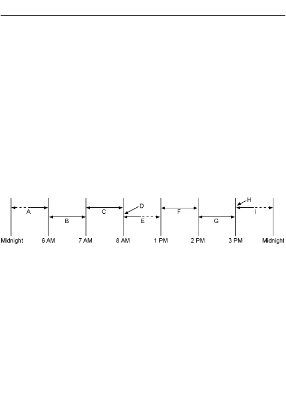
Control Panel Schedules | en 201
Bosch Security Systems, Inc. Program Entry Guide 2017.03 | 03 | F.01U.323.389
11 Schedules
11.1 Open/Close Windows
Use these windows to set a schedule for disarming and arming. The disarming and arming
schedules provide several independent features:
– Suppress normal opening and/or closing reports when Disable O/C in Window, page 101 is
set to Yes.
– Generate a FAIL TO OPEN report if the area is not disarmed on schedule when Fail to
Open, page 102 is set to Yes.
– Provide a warning tone and [PLEASE CLOSE NOW] display at the keypad when it is time
to arm the area.
– Generate a FAIL TO CLOSE report if the area is not armed on schedule when Fail to Close,
page 102 is set to Yes.
– Automatically arm the area at the end of the closing window when Auto Close, page 101 is
set to Yes.
Opening and closing schedules can be set up independently. For example, if you only want to
use features provided by closing windows, leave times blank in the opening windows
parameters and program closing window times.
11.1.1 Opening window timeline
Example using two opening windows on the same day
Areas that are disarmed between midnight and 6 AM generate Opening reports.
Areas that are disarmed between 6 AM and 7 AM generate Early to Open reports.
If the area is disarmed between 7 AM and 8 AM regular Opening Reports are generated.
If Disable O/C in Window is programmed as "yes" the Opening Report is not transmitted to the
central station.
If the area is not disarmed by 8:01 AM then a Fail to Open event is generated if Fail to Open is
programmed as "yes" in Opening and Closing Options.
If the user disarms the area between 8:01 AM and 12:59 PM then a Late to Open event is
generated.
Areas that are disarmed between 1 PM and 2 PM generate Early to Open reports.
If the area is disarmed between 2 PM and 3 PM regular Opening Reports are generated.
If Disable O/C in Window is programmed as "yes" the Opening Report is not transmitted to the
central station.
If the area is not disarmed by 3:01 PM then a Fail to Open event is generated if Fail to Open is
programmed as "yes" in Opening and Closing Options.
If the user disarms the area between 3:01 PM and 11:59 PM then a Late to Open event is
generated.

202 en | Schedules Control Panel
2017.03 | 03 | F.01U.323.389 Program Entry Guide Bosch Security Systems, Inc.
Programming for two Opening Windows on the same day (as shown in the time line)
Open Close
W# Day of
the week
Early
begin
Start Stop Early
begin
Start Stop Except
on
Holiday
1 SMTWT
FS
06:00 07:00 08:00 23:59 Yes / No
2 SMTWT
FS
13:00 14:00 15:00 01:00 Yes / No
Do not program a single window to cross the midnight boundary. The window stop time must
be later than the window start time. To program a window that effectively crosses the
midnight boundary, you have to program two windows.
For example, to program windows for an area that opens between 11:30 PM and 12:30 AM,
five days a week, use two windows as shown in the example below:
Programming to Link Two Days Over Midnight
Open Close
W# Early
begin
Start Stop Early
begin
Start Stop Except
on
Holiday
Holiday
index
Area(s)
1 /
Monday
22:00 23:30 23:59 Yes /
No
1234 123456
78
2 /
Monday
00:00 00:00 00:30 Yes /
No
1234 123456
78
11.1.2 Opening_Closing windows table
Monday to Friday, opening between 5 and 6 AM, closing between 11 PM and 1 AM.
Open Close
W# Day of
the week
Early
begin
Start Stop Early
begin
Start Stop Except
on
Holiday
1 SMTWT
FS
04:00 05:00 06:00 20:00 23:00 23:59 Yes / No
2 SMTWT
FS
00:00 00:00 01:00 Yes / No
Sunday, in between 8 and 8:30 AM, out between 2:30 and 5:00 PM.
Open
W# Day of week Early begin Start Stop
4 SMTWTFS 07:00 08:00 08:30
All days must be
programmed NO
Only on holidays

Control Panel Schedules | en 203
Bosch Security Systems, Inc. Program Entry Guide 2017.03 | 03 | F.01U.323.389
Opening/Closing Windows Table
Use this table to determine the proper entries for your application.
Day of week The column
below briefly
describes the
ways to activate
an Opening/
Closing window.
Use the
guidelines shown
in the other
columns to
choose the
appropriate
entries.
Except on
holiday
Holiday index Areas
Program at least
one day as YES
Days(s) of the
week
NO None Program at least
on area as YES
Program at least
one day as YES
Day(s) of the
week, but NOT
on holidays
YES Select at least
one Index
Program at least
on area as YES
Program at least
one day as YES
Day(s) of the
week, PLUS
holidays
NO Select at least
one Index
Program at least
on area as YES
All days must be
programmed NO
Only on holidays NO Select at least
one Index
Program at least
on area as YES
11.1.3 Sunday through Saturday
Default (Sunday through Saturday): No
Selections: Yes/No
In the seven weekday parameters, select the days of the week that the opening and/or closing
windows are active.
To prevent the windows from activating on certain days of the year, set Xept Holiday, page 209
to Yes, and enable at least one holiday index. When Xept Holiday, page 209 is set to Yes, the
window executes on the days of the week programmed unless the date is designated as a
holiday by the selected holiday index.
If opening and/or closing windows are only needed on certain days of the year, do not
program the windows to execute on any days of the week. Instead, set Xept Holiday, page 209
to No, and select a holiday index with the days of the year you want the window to be active.
RPS Menu Location
Schedules > Open/Close Windows > Sunday through Saturday
11.1.4 Open Early Begin
Default:Disable
Selections:Disable, HH:MM (hours and minutes) 00:00 to 23:59

204 en | Schedules Control Panel
2017.03 | 03 | F.01U.323.389 Program Entry Guide Bosch Security Systems, Inc.
This parameter is one of three required to create an opening window. To finish programming
an opening window, Open Window Start, page 204 and Open Window Stop, page 205 also must
be programmed.
The time entered in this parameter is the earliest time that the user is allowed to open an area
before the Open Window Start, page 204 time. If opening and closing reports are enabled,
disarming the area between midnight and the Open Early Begin time generates an opening
report.
– If Disable O/C in Window, page 101 is set to Yes and the area is disarmed between the
Open Early Begin time and the Open Window Start time, the opening event is sent with
an Early to Open modifier. If the Open Early Begin time is the same as the Open Window
Start time, no opening event is sent.
– If Disable O/C in Window, page 101 in Window is set to No and the area is disarmed at any
time, an opening event is sent without an Early to Open or Late to Open modifier.
Disarming the area between the Open Window Start and Open Window Stop times creates a
local event in the control panel event log, but does not send the opening report to the central
station.
Disarming the area between the Open Window Stop time and before the next window's Open
Early Begin time (or midnight, whichever is earlier) generates an opening event with a Late to
Open modifier.
When configuring multiple windows to operate on the same day, ensure that they are added to
the system in chronological order. For example, if three windows are programmed to execute
on Tuesday, Window 1 (W1) must occur before Window 2 (W2), and Window 2 must occur
before Window 3 (W3).
– Avoid programming the Open Early Begin time before a time that is between another
window's Open Window Start and Open Window Stop times.
– Do not program a window to cross the midnight boundary.
Disabled windows have a 00:00 beginning time. If the entry for this parameter is 00:00, but
times are programmed for Open Window Start and Open Window Stop, the window is
disabled.
To disable the window, all hours and minutes spaces must be 00:00.
Ensure time entries use a 24-hour clock. For example, midnight = 00:00; 7:00 AM = 07:00; 2:45
PM = 14:45; 11:59 PM = 23:59.
If the window needs to activate on the same day you program it, reboot the control panel to
activate today's window.
RPS Menu Location
Schedules > Open/Close Windows > Open Early Begin
11.1.5 Open Window Start
Default:Disable
Selections:Disable, HH:MM (hours and minutes)
This parameter is one of three required to create an opening window. Enter the time that you
want the control panel to start the opening window. The window goes into effect at the
beginning of the minute.
00:00 is Midnight 23:59 is 11:59 P.M. Make entries using a 24-hour clock (for example, 7:00
AM is entered as 07:00, 2:45 PM is entered as 14:45).
To program an opening window, Open Early Begin and Open Window Stop must also be
programmed.
RPS Menu Location
Schedules > Open/Close Windows > Open Window Start

Control Panel Schedules | en 205
Bosch Security Systems, Inc. Program Entry Guide 2017.03 | 03 | F.01U.323.389
Additional resources
Close Early Begin, page 205
Open Window Stop, page 205
11.1.6 Open Window Stop
Default:Disable
Selections:Disable, HH:MM (hours and minutes)
Enter the time that you want the control panel to end the opening window. The window stops
at the end of the minute.
00:00 is Midnight 23:59 is 11:59 P.M. Make entries using a 24-hour clock (for example, 7:00
AM is entered as 07:00, 2:45 PM is entered as 14:45).
This parameter is one of three required to create an opening window. To program an opening
window, Close Early Begin, page 205 and Open Window Start, page 204 must also be
programmed.
If the area is not disarmed by the time the Open Window Stop, page 205 time expires, the
control panel generates a FAIL TO OPEN report if enabled in Fail to Open, page 102.
Opening reports generated between the Open Window Start time and Open Window Stop
time can be suppressed by setting Disable O/C in Window, page 101 to Yes. Refer to Open
Early Begin for other report feature explanations.
Do not use a time of 23:59 as a window stop time unless another window begins on the next
day at 00:00.
The control panel does not send FAIL TO OPEN reports for windows that stop at 23:59.
RPS Menu Location
Schedules > Open/Close Windows > Open Window Stop
11.1.7 Close Early Begin
Default:Disable
Selections:Disable, HH:MM (hours and minutes) 00:00 to 23:59
This parameter is one of three required to create a closing window. To finish programming a
closing window, Close Window Start, page 206 and Close Window Stop, page 206 must be
programmed.
The time entered in this parameter is the earliest time the user can close an area before the
Close Window Start time. If opening and closing reports are enabled, arming the area between
midnight and the time entered in this parameter generates a closing report.
If Disable O/C in Window, page 101 is set to Yes and the area is armed between the Close Early
Begin time and the Close Window Start time, the closing event is sent with an Early to Close
modifier. If the Close Early Begin time is the same as the Close Window Start time, no closing
event is sent.
If Disable O/C in Window is set to No and the area is armed at any time, a closing event is sent
without the Early to Close or Late to Close modifiers.
Arming the area between the Close Window Start and Close Window Stop times creates a
local event in the control panel event log, but does not send the closing report to the central
station.
Arming the area after the Close Window Stop time and before the next window's Close Early
Begin time (or midnight, whichever is earlier) generates a closing event with a Late to Close
modifier.
When configuring multiple windows to operate on the same day, ensure that they are added to
the system in chronological order. For example, if three windows are programmed to execute
on Tuesday, Window 1 (W1) must occur before Window 2 (W2), and Window 2 must occur
before Window 3 (W3).

206 en | Schedules Control Panel
2017.03 | 03 | F.01U.323.389 Program Entry Guide Bosch Security Systems, Inc.
Avoid programming the Open Early Begin, page 203 time that is between another window's
Open Window Start, page 204 and Open Window Stop, page 205 times.
Disabled windows have a 00:00 start time. If the entry for this parameter is 00:00, but times
are programmed for Close Window Start and Close Window Stop, the window is disabled.
To disable the window, both the hours and minutes spaces must be 00:00.
Ensure time entries use a 24-hour clock. For example, midnight = 00:00; 7:00 AM = 07:00; 2:45
PM = 14:45; 11:59 PM = 23:59.
If the window needs to activate on the same day you program it, reboot the control panel to
activate today's window.
RPS Menu Location
Schedules > Open/Close Windows > Close Early Begin
11.1.8 Close Window Start
Default:Disable
Selections:Disable, HH:MM (hours and minutes)
This parameter is one of three required to create a closing window. Enter the time that you
want the control panel to start the closing window. The window goes into effect at the
beginning of the minute.
00:00 is Midnight 23:59 is 11:59 P.M. Make entries using a 24-hour clock (for example, 7:00
AM is entered as 07:00, 2:45 PM is entered as 14:45).
To program a closing window, Close Early Begin, page 205 and Close Window Stop, page 206
must also be programmed.
A warning tone sounds and [PLEASE CLOSE NOW] displays at the keypad if the area is not
armed when the Close Window Start time comes. To temporarily silence the tone, press the
[ESC] key on the keypad. The warning tone restarts in 10 minutes if the area is not armed.
Refer to Close Early Begin, page 205 for report feature explanations.
RPS Menu Location
Schedules > Open/Close Windows > Close Window Start
11.1.9 Close Window Stop
Default:Disable
Selections:Disable, HH:MM (hours and minutes)
This parameter is one of three required to create a closing window. Enter the time that you
want the control panel to end the closing window. The window stops at the end of the minute.
00:00 is Midnight 23:59 is 11:59 P.M. Make entries using a 24-hour clock (for example, 2:45
PM is entered as 14:45).
To program a closing window, Close Early Begin and Close Window Start must also be
programmed.
If the area is not armed by the time the Close Window Stop time expires, the control panel
generates a FAIL TO CLOSE report if enabled in Fail To Close.
Closing reports generated between the Close Window Start time and Close Window Stop time
can be suppressed by setting Disable O/C in Window to Yes. Refer to Close Early Begin for
other report feature explanations.
Do not use a time of 23:59 as a window stop time unless the window continues on the next
day at 00:00. FAIL TO CLOSE reports are not sent, and the Auto Close feature does not work
for windows that stop at 23:59.
Do not program a single window to cross the midnight boundary. The window stop time must
be later than the window start time. To program a window that effectively crosses the
midnight boundary, you have to program two windows.

Control Panel Schedules | en 207
Bosch Security Systems, Inc. Program Entry Guide 2017.03 | 03 | F.01U.323.389
For example, to program windows for an area that closes between 11:30 PM and 12:30 AM,
five days a week, use two windows as shown:
Open Close
W# Day of
week
Early
begin
Start Stop Early
begin
Start Stop Except
on
holiday
1SMTWT
FS
22:00 23:30 23:59 Yes / No
2 SMTWT
FS
00:00 00:00 00:30 Yes / No
RPS Menu Location
Schedules > Open/Close Windows > Close Window Stop
11.1.10 Xept on Holiday
Default:No
Selections:
Yes Do not activate this window on holidays.
NoA holiday does not prevent this window from activating.
This parameter allows you to determine if the window is disabled on holidays, or is active only
on holidays.
To prevent the windows from activating on certain days of the year, set Xept Holiday to Yes,
and enable at least one holiday index. When Xept Holiday is set to Yes, the window executes
on the days of the week programmed unless the date is designated as a holiday by the
selected holiday index(es).
To use this parameter, the window must be programmed to activate on at least one day of the
week and a holiday index must be enabled.
You also use this selection if opening and/or closing windows are only needed on certain days
of the year. Do not program the windows to execute on any days of the week. Instead, set
Xept Holiday to No, and select at least one holiday index with the days of the year you want
the window to be active.
RPS Menu Location
Schedules > Open/Close Windows > Xept on Holiday
Further information
Holiday #, page 209
11.1.11 Holiday #
Default (Holiday 1): No
Selections:
Yes: Use the selected holiday index with this window.
No: Do not use the selected holiday index with this window.
This parameter enables up to four holiday indexes for use with Opening/Closing windows.
Enable at least one holiday index if Xept Holiday, page 209 is set to Yes for this window, or if
you want this window to activate only on specific dates.
RPS Menu Location
Schedules > Open/Close Windows > Holiday 1 to 8

208 en | Schedules Control Panel
2017.03 | 03 | F.01U.323.389 Program Entry Guide Bosch Security Systems, Inc.
11.1.12 Area #
Default:No
Selections:
YesActivate the window in the specified area number.
NoDisable the window in the specified area number.
This parameter determines whether a particular window activates in each of the control
panel's areas.
RPS Menu Location
Schedules > Open/Close Windows > Area #
11.2 User group windows
In this section, you can create up to eight User Group periods in which the passcodes for the
group chosen will be enabled. One user group can have multiple windows assigned to them
within a 24 hour period. Refer to User Group, in the Passcode Worksheet section of the
program to assign individuals to a group.
When you assign a User Group to one of the eight windows, all passcodes for the group are
enabled only for the period between the Enable Time and Disable Time for assigned User
Window #.
If a user is not assigned to a User Group or the number programmed for the user for User
Group is not assigned to a User Window # , the passcode for that user is enabled all the time.
11.2.1 User Group
Default: (window #)
Selections:
– B6512G: 0 to 6
0 = disabled
Enter a number to identify the group of users in this parameter. When this window runs, the
user passcodes for this group are enabled / disabled.
You can assign a user group to more than one window in a 24 hour period, but the windows
must not overlap or exceed the midnight boundary.
RPS Menu Location
Schedules > User Group Windows > User Group
11.2.2 Sunday through Saturday
Default (Sunday through Saturday): No
Selections: Yes/No
In the seven weekday parameters, select the days of the week that the User Group window is
active.
To prevent the windows from activating on certain days of the year, set Xept Holiday to Yes,
and enable at least one holiday index. When Xept Holiday is set to Yes, the window executes
on the days of the week programmed unless the date is designated as a holiday by the
selected holiday index.
If opening and/or closing windows are only needed on certain days of the year, do not
program the windows to execute on any days of the week. Instead, set Xept Holiday to No,
and select a holiday index with the days of the year you want the window to be active.
RPS Menu Location
Schedules > User Group Windows > Sunday through Saturday
Control Panel Schedules | en 209
Bosch Security Systems, Inc. Program Entry Guide 2017.03 | 03 | F.01U.323.389
Additional Information
Xept Holiday, page 209
11.2.3 Group Enable Time
Default: Disable
Selections:Disable, HH:MM (hours and minutes)
Enter the time of day that the window starts. Beginning at this time, users assigned to this
window's group are allowed to use their passcodes. The window goes into effect at the
beginning of the minute.
Notice!
This parameter must be programmed if this User Group Window is assigned to a user group.
Make entries using a 24-hour clock (for example, 2:45 PM is entered as 14:45).
When disabling Group Enable Time input, the time reverts back to 00:00.
Perform a Reset Panel command when ending the communications session to activate today's
window. If you are programming a window that needs to activate on the same day that you are
programming it, do a Reset Panel command after programming.
RPS Menu Location
Schedules > User Group Windows > Group Enable Time
11.2.4 Group Disable Time
Default: Disable
Selections:Disable, HH:MM (hours and minutes)
Enter the time of day when the window ends. This time marks the end of the period in which
users assigned to this window's group can use their passcodes. The window stops at the end
of the minute.
Notice!
This parameter must be programmed if this user group window is assigned to a user group.
Make entries using a 24-hour clock. For example, 2:45 PM = 14:45.
To disable the window, both the hours and minutes spaces must be blank.
Do not program a single window to cross the midnight boundary. The window stop time must
be later than the window start time.
RPS Menu Location
Schedules > User Group Windows > Group Disable Time
11.2.5 Xept Holiday
Default:No
Selections:Yes/No
This parameter allows you to determine if the window is disabled on holidays, or is active only
on holidays. Use the instructions provided in Xept Holiday.
RPS Menu Location
Schedules > User Group Windows > Xept Holiday
11.2.6 Holiday #
Default: No

210 en | Schedules Control Panel
2017.03 | 03 | F.01U.323.389 Program Entry Guide Bosch Security Systems, Inc.
Selections:
Yes: Use the selected holiday index with this window.
No: Do not use the selected holiday index with this window.
This parameter enables up to four holiday indexes to use with User Group Windows.
Enable at least one holiday index if Xept Holiday is set to Yes for this User Window, or if you
want this window to activate only on specific dates.
RPS Menu Location
Schedules > User Group Windows > Holiday #
11.3 Skeds
Use the SKEDS module to program the control panel to automatically execute functions-that
are otherwise initiated by the end user at the keypad. Each Sked can be programmed to occur
at a specific time on a specific date or day of the week.
A Sked can be edited from the keypad if Time Edit is set to Yes. The date and time can be
changed using the [CHANGE SKED?] function.
Each Sked Number can be programmed with one of 24 functions for the Function. A function
is what is executed. In addition to the function, a choice must be made to what is affected by
the function. (e.g. When choosing a Disarm Sked, the disarming is the function while the areas
that are being chosen to become disarmed are what is affected).
The functions and their associated parameters are explained in detail following the Function
parameter.
Each Sked can be programmed with up to four Holiday Indexes. The Holiday Indexes can be
used to execute the Sked on the Holidays in addition to the Date or Day(s) of the Week, or,
they can be used to prevent the Sked from executing on the Holidays (Refer to Xept Holiday ).
11.3.1 Sked Name Text
Default: Sked #
Selections: Up to 32 alphanumeric characters
Enter up to 32 characters of text to describe the area.
This is for informational purposes only and is not sent to the control panel.
RPS Menu Location
Schedules > Skeds > Sked Name Text
11.3.2 Sked Name Text (Second Language)
Default: Blank
Selections: Up to 32 alphanumeric characters
Enter up to 32 characters of text to describe the area. This is for informational purposes only
and is not sent to the control panel.
RPS Menu Location
Schedules > Skeds > Sked Name Text (second language)
11.3.3 Time Edit
Default:Yes
Selections:
Yes. The user can edit the time of this Sked from the keypad, and it appears in the CHANGE
SKED display.
No. The user cannot edit the time of this Sked from the keypad, and it does not appear in
the CHANGE SKED displays.
Select whether the user can edit the time of this Sked from the keypad.

Control Panel Schedules | en 211
Bosch Security Systems, Inc. Program Entry Guide 2017.03 | 03 | F.01U.323.389
RPS Menu Location
Schedules > Skeds > Time Edit
11.3.4 Function
Default: Not in Use
Selections: See list of Sked functions below.
Select the function name from the drop down list that you want this Sked to execute.
RPS automatically displays the available parameter choices and range fields for this function.
(e.g. A list of check boxes are automatically displayed for the areas when choosing the arm/
disarm function.
Notice!
The All On - No Exit feature is ignored when arming from a SKED.
Click on a function name for information about that function.
Not In Use - This function is disabled and no functions after this will be performed.
All On Delay, page 213
All On Instant, page 214
Part On Delay, page 214
Part On Instant, page 214
Disarm, page 214
Extend Close, page 214
Bypass a Point, page 214
Unbypass a Point, page 214
Unbypass All Points, page 214
Reset Sensors, page 214
Turn Output On, page 214
Turn Output Off, page 215
Toggle Output, page 215
One-Shot Output, page 215
Reset All Outputs, page 215
Delay, page 215
Cycle Door
Unlock Door
Lock Door
Secure Door
Access Ctrl Level
Access Granted Events
Access Denied Events
Answer RPS, page 215
Contact RPS, page 215
Contact RPS User Port, page 216
Send Status Report, page 216
Send Test Report, page 216
Send Test on Off Normal, page 217
Go to Area, page 217
Watch On, page 217
Watch Off, page 217
Show Date & Time, page 217

212 en | Schedules Control Panel
2017.03 | 03 | F.01U.323.389 Program Entry Guide Bosch Security Systems, Inc.
Sound Watch Tone, page 217
Set Keypad Volume, page 218
Set Keypad Brightness, page 218
Trouble Silence, page 218
Alarm Silence, page 218
RPS Menu Location
Schedules > Skeds > Sked 1-80 > Function
11.3.5 Time
Default: Disable
Selections:Disable, HH:MM (hours and minutes)
Enter the time that the Sked executes using a 24-hour clock (for example, 2:45 PM is entered
as 14:45).
Disabled Skeds displays "Disabled"in the cell.
Follow these steps to program a time:
1. Double-click on the field corresponding to the Sked you wish to program the time for.
2. If "Disable" is checked, uncheck it. The time field will become active.
3. Click inside the time field and either use the up and down arrows to set the time, or type
in the desired time.
4. Click on OK.
Follow these steps to Disable a Sked:
1. Double-click on the field corresponding to the Sked you wish to disable.
2. Select "Disable".
3. Click OK.
RPS Menu Location
Schedules > Skeds > Time
11.3.6 Date
Default:Disable
Selections:Disable, Day/Month (ex. 12 June)
Enter the date that the Sked executes. Disabled Skeds display "Disabled" in the Date cell.
RPS Menu Location
Schedules > Skeds > Date
11.3.7 Sunday through Saturday
Default (Sunday through Saturday): No
Selections: Yes/No
These seven day of the week parameters select the days of the week that the Sked is active.
To prevent the Sked from activating on certain days of the year, set Xept on Holiday, page 213
to Yes, and enable at least one holiday index. When Xept Holiday is set to Yes, the window
executes on the days of the week programmed unless the date is designated as a Holiday by
the Holiday Index selected.
If a Sked is only needed on certain days of the year, do not program the Sked to execute on
any days of the week. Instead, set Xept Holiday to No, and select a holiday index with the
dates you want the window to be active.
RPS Menu Location
Schedules > Skeds > Sunday through Saturday

Control Panel Schedules | en 213
Bosch Security Systems, Inc. Program Entry Guide 2017.03 | 03 | F.01U.323.389
11.3.8 Xept on Holiday
Default: No
Selections:
– Yes. Prevent this Sked from operating on the Holidays identified in the specific Holiday
Index(es) used with this Sked. Specific Holiday Indexes are selected in this programming
section and programmed in the next programming module.
– No. This Sked operates on Holidays programmed in the Holiday Index(es) used with
this Sked.
If no Days of the Week are programmed, this Sked operates only on the Holidays programmed
in the Holiday Index(es) used with this Sked. This Sked also operates if the Holiday falls on a
day of the week that is programmed.
RPS Menu Location
Schedules > Skeds > Xept on Holiday
11.3.9 Holiday #
Default: No
Selections:
Yes: Use the selected holiday index with this window.
No: Do not use the selected holiday index with this window.
This parameter enables up to four holiday indexes to use with User Group Windows.
Enable at least one holiday index if Xept Holiday is set to Yes for this User Window, or if you
want this window to activate only on specific dates.
RPS Menu Location
Schedules > Skeds > Holiday #
11.4 Holiday indexes
11.4.1 Schedule
Holiday Indexes Schedule
This parameter sets holidays.
Within each index, you can select up to 365 dates (or 366 dates for a Leap Year) to be
designated as Holidays. Double-click in a cell corresponding to the Holiday Index you wish to
program. The Holiday Schedule dialog appears. This dialog is formatted to look like a calendar.
It opens to the current month and year.
The year is for reference purposes only. RPS only sends the month and day information to the
Panel. When a day is chosen to be a holiday in a specific year that same day will be a holiday
in every year thereafter. However, the day of the week will shift according to the year being
viewed. For example if October 24, 2012, is set as a holiday, October 24 will be a holiday in
2013, 2014, and so on. But the holiday will fall on different days of the week.
RPS Menu Location
Schedules > Holiday Index > Holiday Indexes Schedule
11.5 Sked Function descriptions
11.5.1 All On Delay
This function simulates the All On Delay keypad function. Selections in the Parameter 1: Area #
prompt define the area(s) this Sked arms. The Sked can arm multiple areas. If any point is
faulted when the Sked executes, it is force armed regardless of FA/Bypass max.

214 en | Schedules Control Panel
2017.03 | 03 | F.01U.323.389 Program Entry Guide Bosch Security Systems, Inc.
11.5.2 All On Instant
This function simulates the All On Instant keypad function. Entries in the Parameter 1: Area #
field define the area(s) this Sked arms. The Sked can arm multiple areas. If any point is faulted
when the Sked executes, it is force armed regardless of FA/Bypass max.
11.5.3 Part On Delay
This function simulates the Part On Delay keypad function. Selections in the Parameter 1: Area
# prompt define the area(s) this Sked arms. The Sked can arm multiple areas. If any point is
faulted when the Sked executes, it is force armed regardless of FA/Bypass max.
11.5.4 Part On Instant
This function simulates the Part On Instant keypad function. Selections in the Parameter 1:
Area # prompt define the area(s) this Sked arms. The Sked can arm multiple areas. If any point
is faulted when the Sked executes, it is force armed regardless of FA/Bypass max.
11.5.5 Disarm
This function emulates the Disarm keypad function. Selections in the Parameter 1: Area #
prompt define the area(s) this Sked disarms. The Sked can disarm multiple areas.
11.5.6 Extend Close
This function sets the closing window start time to the current time plus the number of
minutes configured in Parameter 2. This function can only take effect after the Close Early
Begin time has passed.
Notice!
Extend Close time cannot extend past midnight. Furthermore, if enabled, it cannot extend
past an area's configured Latest Close Time.
11.5.7 Bypass a Point
This function emulates the Bypass Point keypad function. The entry in the Parameter 1: Point
#prompt defines the point this Sked bypasses. The point can be bypassed only if Bypassable
is programmed YES in the Point Index assigned to the point. The bypass is reported if Bypass
Reports are enabled in the Point Index assigned to the point. The Sked can bypass one point.
11.5.8 Unbypass a Point
This function emulates the Unbypass Point shortcut keypad function. The entry in the
Parameter 1: Point # prompt defines the point this function unbypasses. This function can only
bypass one point.
11.5.9 Unbypass All Points
This function is not available as a shortcut keypad function. The areas selected in the
Parameter 1: Area # prompt define the areas where this function unbypasses all points.
11.5.10 Reset Sensors
This function emulates the keypad shortcut Reset Sensors. When activated, this function
activates the area-wide-output Reset Sensors for 5 seconds. This function de-activates the
alarm output for areas selected in Parameter 1 for five seconds.
11.5.11 Turn Output On
This function emulates the Change Output State keypad shortcut to turn outputs on.

Control Panel Schedules | en 215
Bosch Security Systems, Inc. Program Entry Guide 2017.03 | 03 | F.01U.323.389
The entry in the Parameter 1: Output # prompt defines the specific output this function
activates. The function can activate one output.
11.5.12 Turn Output Off
This function emulates the Change Output State keypad shortcut to turn outputs off.
The entry in the Parameter 1: Output # prompt defines the specific output this function
deactivates. The function can deactivate one output.
11.5.13 Toggle Output
This function is not available as a keypad shortcut function. The entry in the Parameter 1:
Output # prompt defines the specific output this function toggles. If the output is on, it is
turned off. If the output is off, it is turned on. The function has effect on one output.
11.5.14 One-Shot Output
This function is not available as a keypad shortcut function and is only available as a custom
function. The function activates the output selected in Parameter 1 for the number of seconds
selected in Parameter2.
11.5.15 Reset All Outputs
This function is not available as a keypad shortcut function. This function turns off all outputs
that are turned on by a sked or custom function. This is a panel-wide function. No other
parameters require input for this option.
11.5.16 Delay
Use this function to create a configurable delay (0 to 90 seconds) between, or before
functions. Parameter 1 configures the delay.
11.5.17 Answer RPS
This function emulates the keypad short cut Answer RPS which causes the control panel to
answer the next request from RPS to establish a session via phone or network. This function is
only available in a custom function. This auto-answer period will last for 2 minutes and
overrides the Answer RPS Over Network? and RPS Address Verification prompt settings.
11.5.18 Contact RPS
This function attempts to contact an Unattended RPS at the configured time. The control
panel's account in RPS controls the operations performed upon successful contact.
Notice!
Avoid having multiple functions occur at the same time at the same address. Functions can
clash and the effect on the panel is unpredictable.
Notice!
Do not program multiple Skeds to execute at the same keypad during the same time of
execution.
Notice!
Do not program Skeds to execute at times when a user is likely to be executing functions at
the keypad.

216 en | Schedules Control Panel
2017.03 | 03 | F.01U.323.389 Program Entry Guide Bosch Security Systems, Inc.
11.5.19 Contact RPS User Port
This function attempts to contact Unattended RPS at the configured time over a network
communication device at the configured port. The control panel's account in RPS controls the
operations performed upon successful contact.
11.5.20 Send Status Report
This function generates a status report for each area that is enabled. The report is sent to the
Phone(s) programmed for Test and Status Reports in Report Routing.
The status report can be deferred if any other report was sent since the last status report. To
defer the status report for up to 24 hours, set the Parameter 1: Deferred option to Yes.
11.5.21 Send Test Report
This sked function emulates the Test Report keypad function. This function generates a test
report from Area 1 that includes panel wide status information. The report is sent based on
the Report Routing configuration under Panel Wide Parameters > Report Routing > Test
Reports > Test Reports, page 54.
If Expand Test Report, page 31 in Panel Wide > Phone and Phone Parameters is programmed
Yes, the test report also includes all off-normal states for events listed in Panel Wide
Parameters > Report Routing > Diagnostic Reports, page 54 and Test Reports.
Selections, Parameter 1: Deferred
– Yes - defer sending test reports for 24 hours if any other report is sent.
– No - do not defer sending test reports.
Notice!
Only sending the test report is deferred
When Parameter 1: Deferred is set to Yes, only sending the test report is deferred. The Send
Test Report sked still runs at the frequency set in Parameter 2: Frequency.
Selections, Parameter 2: Frequency
– Hourly - The first Send Test Report sked runs at the time entered in the Time parameter
for the Sked. The Send Test Report sked runs every hour after that.
– Monthly - The first Send Test Report sked runs at the time entered in the Time parameter
for the sked, on the date entered in the Date parameter. The Send Test Report sked runs
every month after that.
– Scheduled - The Send Test Report sked runs annually on the date entered in Date
parameter, at the time entered in the Time parameter.
Deferring test reports
When Parameter 1: Deferred is set to Yes, the control panel starts (or restarts) a 24 hour
countdown timer each time it receives an Ack (acknowledgement) from the central station
receiver for any report.
If Parameter 2 is set to Hourly, and the panel has not received an Ack by the time the first
hourly Send Test Report sked runs, the panel sends the test report. If the panel received an
Ack, test reports are deferred for 24 hours from the last Ack received. The hourly Send Test
Report sked will not send a test report for at least 24 hours.
If Parameter 2 is set to Monthly, and the panel has not received an Ack within 24 hours of the
time the first monthly Send Test Report sked runs, the panel sends the test report. If the
panel receives an Ack within 24 hours of the time a monthly Send Test Report sked is set to
run, the test report is deferred for 24 hours from the last Ack received. If the 24 hour
countdown timer expires, the panel sends the deferred test report at that time.
Control Panel Schedules | en 217
Bosch Security Systems, Inc. Program Entry Guide 2017.03 | 03 | F.01U.323.389
If Parameter 2 is set to Scheduled, and the panel has not received an Ack within 24 hours of
the time the scheduled Send Test Report sked runs, the panel sends the test report. If the
panel receives an Ack within 24 hours of the time a scheduled Send Test Report sked is set to
run, the test report is deferred for 24 hours from the last Ack received. If the 24 hour
countdown timer expires, the panel the deferred test report at that time.
11.5.22 Send Test on Off Normal
In order to generate this event, one or more points must be in an off-normal state at the time
the Sked executes. Expanded Off-Normal Test Reports include the Off Normal Test Report
event as well as events for any points that are in an off-normal state at the time the report is
generated.
This function sends the following report to the central station if the point is in an off-normal
state:
Modem event Contact ID event Contact ID code
Test Report – System off-
normal, expanded status
Periodic Test – System
Trouble Present
1 608 00 000
Non-Expanded Off-Normal Test Report events are only sent when any point is in the off-normal
state from any area but only sends the Off Normal Test Report event.
11.5.23 Go to Area
This function emulates the Go To Area keypad shortcut and is only available to custom
functions activated through a keypad. When activated, this function will change the keypads
current area to the one programmed in Parameter 1: Area #.
11.5.24 Watch On
This function emulates the operation of the keypad shortcut Change Watch Mode by activating
Match mode for the areas programmed in Parameter 1: Area #. Watch mode causes a chime at
any keypad within scope when a watch point is faulted while disarmed.
11.5.25 Watch Off
This function emulates the operation of the keypad shortcut Change Watch Mode by
deactivating Match mode for the areas programmed in Parameter 1: Area #.
11.5.26 Show Date & Time
This function emulates the keypad shortcut Show Date & Time by displaying the current time
and date at the SDI2 keypads specified in Parameter 1: Keypads #.
Notice!
When using the Show Date & Time function with the Set Keypad Volume or Set Keypad
Brightness functions in the same custom function they must be separated by about 10
seconds with the Delay function.
11.5.27 Sound Watch Tone
This function is not available as a keypad shortcut. When activated, this function causes the
SDI2 keypads specified in Parameter 1: Keypads # to continuously emit a watch beep until
silenced.

218 en | Schedules Control Panel
2017.03 | 03 | F.01U.323.389 Program Entry Guide Bosch Security Systems, Inc.
11.5.28 Set Keypad Volume
This function sets the configured keypads shown in Parameter 1: Keypad # to the volume level
entered in Parameter 2: Volume Level. Refer to Keypad Volume, page 116 in the keypad
configuration section for details on volume parameters.
11.5.29 Set Keypad Brightness
This function sets the configured keypads shown in Parameter 1: Keypad # to the brightness
level selected in Parameter 2: Brightness Level. Refer to the Keypad Brightness, page 116
parameter in the keypad configuration section for details on the brightness parameter.
11.5.30 Trouble Silence
This function is not available as a Keypad Shortcut, but can be performed at any keypad
through other means. When activated, this function silences all trouble tones and system
buzzes in the areas programmed in Parameter 1: Area #.
11.5.31 Alarm Silence
This function is not available as a Keypad Shortcut, but can be performed at any keypad
through other means. When activated, this function silences all alarms in the areas
programmed in Parameter 1: Area #.
11.5.32 Execute Custom Function
This function executes the custom function selected in Parameter 1: Custom Function # at a
scheduled time.

Control Panel Access | en 219
Bosch Security Systems, Inc. Program Entry Guide 2017.03 | 03 | F.01U.323.389
12 Access
12.1 Door #
12.1.1 Door Name Text
Default: DOOR#
Selections: Up to 32 alphanumeric characters
Notice!
The B6512 supports Doors 1 to 4.
Enter up to 24 characters of text to describe the door.
This is for informational purposes only and is not programmed in the control panel.
RPS Menu Location
Access > Doors > Door Name Text
12.1.2 Door Name Text (second language)
Default: blank
Selections: Up to 32 alphanumeric characters
Notice!
The B6512G supports Doors 1 to 4.
Enter up to 24 characters of text to describe the door.
This is for informational purposes only and is not programmed in the control panel.
RPS Menu Location
Access > Doors > Door Name Text (second language)
12.1.3 Door Source
Default:Disabled
Selections:
– Disabled. Door module is disabled.
– SDI2 (B901)
Use this parameter to assign each door to a device type.
RPS Menu Location
Access > Doors > Door Source
12.1.4 Entry Area
Default:1
Selections:
– B6512: 1-4
Assign an area to the door controller. This is the area a user exit when initiating a request to
exit (REX).
RPS Menu Location
Access > Doors > Entry
12.1.5 Associated Keypad #
Default:No Keypad

220 en | Access Control Panel
2017.03 | 03 | F.01U.323.389 Program Entry Guide Bosch Security Systems, Inc.
Selections:0 to 32
– B6512: 1 to 12
This parameter sets the door controller to SDI2 keypad associated for KP# Dual
Authentication. A Setting of Disabled also disables Dual Authentication operation.
Enter the Keypad number (KP#) which determines the scope of the user ID's disarming rights.
Areas disarm on the basis of this Keypad's scope and the Authority Level of.
No Keypad: Only the area assigned to the Entry Area, page 219 disarms for this door.
RPS Menu Location
Access > Doors > Associated Keypad #
12.1.6 Custom Function
Default: Disabled
Selections:
– B6512G: Disabled, CF128 to CF133
Disabled: Custom function is disabled.
CF###: The custom function number that activates when a valid ID is entered, given the
appropriate user access level and area arm state.
Use this parameter to program a custom function that activates at the keypad programmed for
Scope, page 109.
This custom function only activates for users with a function level authority that allows a valid
ID to perform a custom function during the armed or disarmed state.
The user to which the card or token is assigned must have an assigned passcode.
The following table shows how this programming affects custom function activation:
Function level Custom function activation
A (armed) User token activates the custom function
assigned to the door controller only when the
entry area for the door controller is All On or
Part On.
D (disarmed) User token activates the custom function
assigned to the door controller only when the
entry area for the door controller is disarmed.
C (armed and disarmed) User token activates the custom function
assigned to the door controller only when the
entry area for the door controller regardless
of the armed state of the entry area.
Blank User token does not activate the custom
function assigned to the door controller.
RPS Menu Location
Access > Doors > Custom Function #
12.1.7 Door Point
Default:0
Selections: 0 (no point assigned), 1-96
Use this parameter to assign a point to a door. This point cannot be used for any other point
assignments.

Control Panel Access | en 221
Bosch Security Systems, Inc. Program Entry Guide 2017.03 | 03 | F.01U.323.389
Door Points must be programmed as Part On points. If a Door Point requires 24 hour point
type behavior, use the Part On point type with a Point Response of 9 to C for instant alarm
response when the area is on (armed) or off (disarmed).
If you select an on-board point (points 1-8) as a Door Point, be sure there is no EOL resistor
connected to the sensor loop on the control panel.
RPS Menu Location
Access > Doors > Door Point
See also
– Debounce, page 173
12.1.8 Door Point Debounce
Default: 600 ms
Selections:
Debounce
300 ms 1800 ms 3300 ms
600 ms 2100 ms 3600 ms
900 ms 2400 ms 3900 ms
1200 ms 2700 ms 4200 ms
1500 ms 3000 ms 4500 ms
This parameter sets the length of time the access control module scans a door point before
initiating an alarm. For appropriate settings, consult the manufacturer's instructions for the
device connected to the door point.
RPS Menu Location
Access > Doors > Door Point Debounce
12.1.9 Interlock Point
Default:0
Selections: 0 (no point assigned), 1-96
Use this parameter to make a point an Interlock Point. An Interlock Point cannot be used for
any other point assignments.
Interlock Points must be programmed as Part On points. If an Interlock Point requires 24 hour
point type behavior, use the Part On point type with a Point Response of 9 to C for instant
alarm response when the area is on (armed) or off (disarmed).
When an Interlock Point is, faulted, it prevents the access control module from granting
access for a valid ID read or door request.
You may use the same point as the Interlock Point for multiple access control modules.
Sharing a point as the Interlock point for multiple modules allows one faulted point to prevent
multiple modules from granting access.
The interlock point will be considered in a normal state if it is bypassed, swinger bypassed, or
forced armed. This results in normal operation of access even if the door is left open.
RPS Menu Location
Access > Doors > Interlock Point
See also
– Debounce, page 173
222 en | Access Control Panel
2017.03 | 03 | F.01U.323.389 Program Entry Guide Bosch Security Systems, Inc.
12.1.10 Auto Door
Default:No
Selections:
– Yes – when the area assigned in Entry Area, page 219 is off (disarmed), the door state is
Unlocked. When that area is on (armed), the door returns to the Locked state.
– No – door state is not affected by the armed state of the area.
Use this program item to unlock the door (latched shunt and strike) automatically when the
entry area is turned off (disarmed). The door re-locks when the area is turned All On or Part
On (armed).
Notice!
Use Secure Door to override Unlocked
You cannot manually override the Unlocked state. Use Secure Door, page 159 to override this
setting.
RPS Menu Location
Access > Doors > Auto Door
12.1.11 Fire Unlock
Default:No
Selections:
Yes:Fire or Gas alarm activates the output and shunts the door point.
No: Door remains in its current mode upon a Fire or Gas alarm.
Use this parameter to activate the output for the door strike and shunt the door point upon a
Fire or Gas alarm. This feature overrides a Secure Door state, Locked Door state, Auto Door,
and an Interlock faulted point. The output activates for all doors when a Fire or Gas alarm
occurs in any area.
Notice!
This unlocks the door regardless of the armed state.
Notice!
You can return doors activated by Fire Unlock to a normal state by pressing 8 – Main menu >
3 – Actions > 8 – Access, or through the keypad with Command 46 – Access menu.
Notice!
For door controllers configured for dual authentication, Fire Unlock is only available if you
configure the associated keypad with a Passcode Enter Function of Cycle Door. All other
Passcode Enter functions use the token reader for authentication and prevent all door
functions including Fire Unlock.
RPS Menu Location
Access > Doors > Fire Unlock
12.1.12 Disarm on Open
Default:No
Selections:
Yes:the area only disarms after access has been granted to a user with disarm authority, and
the door point has been faulted (door was opened).

Control Panel Access | en 223
Bosch Security Systems, Inc. Program Entry Guide 2017.03 | 03 | F.01U.323.389
No:the area disarms when a user with a valid disarm level presents a valid token/card,
whether or not the door has been opened.
Use this program item to determine whether the door needs to be physically opened prior to
disarming the area upon a valid access request. The user initiating the access request must
have access levels that allow disarming with ID.
RPS Menu Location
Access > Doors > Disarm on Open
12.1.13 Strike Time
Default:10
Selections:1 - 240 seconds
The strike activates for the amount of time programmed.
Enter the amount of time the output for the strike activates to allow a user to open the door.
The strike activates upon a valid credential (card), Request to Enter (RTE), Request to Exit
(REX), and the keypad [CYCLE DOOR?] function.
RPS Menu Location
Access > Doors > Strike Time
12.1.14 Shunt Time
Default:10
Selections:
0 – the shunt does not activate for this door.
1 to 240 – the shunt activates for the seconds entered.
Enter the number of seconds the door is shunted to allow a user to open the door without
causing the point to go into Trouble, Alarm, or a faulted condition.
RPS Menu Location
Access > Doors > Shunt Time
12.1.15 Buzz Time
Default:2
Selections:0, 1 - 240 seconds
0:no buzz time for this door.
1 - 240:The buzzer sounds for seconds programmed.
Enter the seconds that the buzzer output activates to notify the user that the strike is
activated and the door is ready to open. The buzzer stops when the door is opened.
A separate buzzer is required.
Many readers have an internal buzzer that is not affected by Buzz Time.
RPS Menu Location
Access > Doors > Buzz Time
12.1.16 Extend Time
Default:10
Selections:0, 1 - 30 seconds
Enter the amount of time (1 to 30) to prolong strike, buzz, and shunt activation when the
shunt time expires and a door remains open. At the end of the programmed Extend Time, the
buzzer continues to buzz until the door closes. In addition, if programmed, the point assigned
to the door indicates a Trouble, Alarm, or Fault at the keypad.

224 en | Access Control Panel
2017.03 | 03 | F.01U.323.389 Program Entry Guide Bosch Security Systems, Inc.
Regardless of the door point programming, the system generates a Trouble Door Left Open
event while the system is disarmed, and an Alarm Door Left Open event when the system is
armed and the door is held open beyond Extend Time. "Door Closed - Restoral" events are
generated after the door is held open past Extend Time and the door has returned to normal.
Enter 0 to disable Extend Time. The Trouble Door Left Open event, the Alarm Door Left Open
event, and the warning at the keypad are all disabled.
RPS Menu Location
Access > Doors > Extend Time
12.1.17 Deactivate on Open
Default:Yes
Selections:
Yes:Strike deactivates when the door point is faulted (door is opened) after access is granted.
No: Strike remains activated for the amount of the programmed strike time whether the door
is opened or closed.
This parameter determines whether the strike deactivates immediately upon physically
opening the door (door point is faulted).
In order for this function to work, a point needs to be assigned in the Door Point, page 220
parameter.
Notice!
To reduce false alarms, leave this programming item at Yes (default). This helps prevent the
door from “bouncing” open and causing a false alarm.
RPS Menu Location
Access > Doors > Deactivate On Open
12.1.18 RTE Shunt Only
Default:No
Selections:
Yes - when the RTE Input (Request To Enter) on the access control module is shorted the door
point is shunted for the duration of Shunt Time, page 223. The strike output is not activated.
No - when the RTE Input on the access control module is shorted the door point is shunted for
the duration of Shunt Time, page 223. The strike output is activated for the duration of Strike
Time, page 223.
Use this parameter when a user can open a door manually without relying on a token/card to
activate the strike (such as with a "push bar").
Notice!
No RTE Events when RTE Shunt Only is set to Yes
When RTE Shunt Only is set to Yes, the control panel does not log or report Request To Enter
events when the RTE Input is shorted.
RPS Menu Location
Access > Doors > RTE Shunt Only
12.1.19 RTE Input Debounce
Default: 600 ms
Selections:
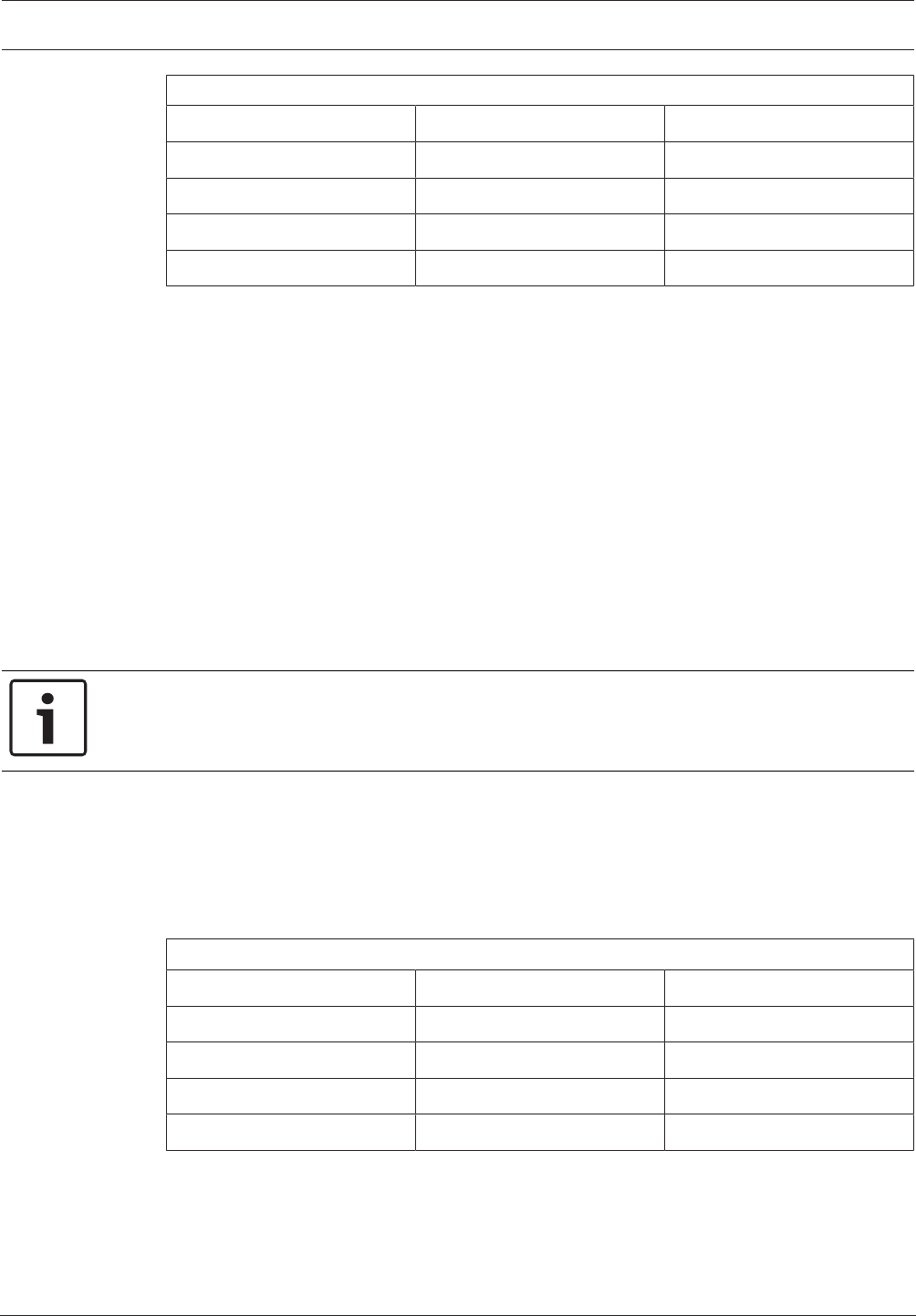
Control Panel Access | en 225
Bosch Security Systems, Inc. Program Entry Guide 2017.03 | 03 | F.01U.323.389
Debounce
300 ms 1800 ms 3300 ms
600 ms 2100 ms 3600 ms
900 ms 2400 ms 3900 ms
1200 ms 2700 ms 4200 ms
1500 ms 3000 ms 4500 ms
This parameter sets the length of time the access control module scans the RTE input before
initiating a request to enter (RTE) event. For appropriate settings, consult the manufacturer's
instructions for the device connected to the RTE input.
RPS Menu Location
Access > Doors > RTE Input Debounce
12.1.20 REX Shunt Only
Default:No
Selections:
Yes:Programmed shunt time will activate so door can be manually opened.
No:Request to Exit (REX) automatically activates the programmed strike and shunt time.
Use this program item to disable the strike, but still activate the programmed shunt time upon
a Request to Exit an area.
Use this parameter when a user can open a door manually without relying on a token/card to
activate the strike (such as with a "push bar").
Notice!
When REXShunt Only is Yes, Request To Exit events are not logged or reported.
RPS Menu Location
Access > Doors > REX Shunt Only
12.1.21 REX Input Debounce
Default: 600 ms
Selections:
Debounce
300 ms 1800 ms 3300 ms
600 ms 2100 ms 3600 ms
900 ms 2400 ms 3900 ms
1200 ms 2700 ms 4200 ms
1500 ms 3000 ms 4500 ms
This parameter sets the length of time the access control module scans the REX input before
initiating a request to exit (REX) event. For appropriate settings, consult the manufacturer's
instructions for the device connected to the REX input.
RPS Menu Location
Access > Doors > REX Input Debounce

226 en | Access Control Panel
2017.03 | 03 | F.01U.323.389 Program Entry Guide Bosch Security Systems, Inc.
12.1.22 Access Granted
Default:Yes
Selections:
Yes:ACCESS GRANTED and DOOR REQUEST events logged and reported.
No:ACCESS GRANTED and DOOR REQUEST events are not logged or reported.
This parameter determines if ACCESS GRANTED and DOOR REQUEST events from this access
control module are logged and reported by the control panel.
An ACCESS GRANTED event can be initiated by:
– a valid read of a crendential (card or token)
– a valid door state changed at the keypad
– an automatically scheduled or armed state changes that hold a door open
RPS Menu Location
Access > Doors > Access Granted
12.1.23 No Entry
Default:Yes
Selections:
Yes:ACCESS DENIED events logged and reported.
No:ACCESS DENIED events are not logged and reported.
This No Entry parameter determines if ACCESS DENIED events from this access control
module are logged and reported by the control panel.
A No Entry (ACCESS DENIED) event may be caused by:
– invalid or unknown user ID, interlock or secured door, or incorrect authority level
– request to enter/exit (RTE/REX) for door in interlock or secured door
RPS Menu Location
Access > Doors > No Entry
12.1.24 Enter Request
Default:No
Selections:
Yes: REQUEST TO ENTER (RTE) events logged and reported.
No: REQUEST TO ENTER (RTE) events are not logged and reported.
This parameter determines if REQUEST TO ENTER (RTE) events from this access control
module are logged and reported by the control panel.
RPS Menu Location
Access > Doors > Enter Request
12.1.25 Exit Request
Default:No
Selections:
Yes: REQUEST TO EXIT (REX) events logged and reported.
No: REQUEST TO EXIT (REX) events are not logged and reported.
This parameter determines if REQUEST TO EXIT (REX) events from this access control module
are logged and reported by the control panel.
RPS Menu Location
Access > Doors > Enter Request
12.1.26 Failure Mode
Default:Fail secure
Selections:
Control Panel Access | en 227
Bosch Security Systems, Inc. Program Entry Guide 2017.03 | 03 | F.01U.323.389
Fail Secure. Door remains locked to ensure continued security.
Fail Safe. Access module releases door locking mechanism to allow passage.
This parameter sets the behavior for the Access Module when it loses communication with the
control panel and enters Failure Mode.
This configuration option only applies to the SDI2 B901 access control modules.
RPS Menu Location
Access > Doors > Failure Mode
12.1.27 Enclosure Tamper
Default: No
Selections:
Yes - enable tamper input (T+).
No - disable tamper input (T+).
Notice!
Enclosure Tamper parameter configures reader tamper input, T+
For the B901 Access Control Interface module, this parameter enables the reader tamper
input (T+ terminal). There is no enclosure tamper input on these modules.
Shorting the B901 tamper input (T+) to common (COM) creates a Point Missing event for the
Door Point, page 220 and a Tamper event for the B901 module.
RPS Menu Location
Access > Doors > Enclosure Tamper
See also
– Door Point, page 220
12.2 Global Access settings
12.2.1 Card Type
Default:26 bit
Selections:
26 bit
37 bit no site code
37 bit with site code
This parameter specifies the card or token format used for all of the door controllers and
keypads.
Notice!
Set to 26 bit when credentials (card or token) are used with a B942.
Default Site Code, page 142 for card types
26 bit:default site code is 255.
37 bit no site code:default site code is blank. The site code is not configurable (Site Code
parameter is grayed out).
37 bit with site code:default site code is 65535.
RPS Menu Location
Access > Global Keypad Settings > Card Type

228 en | Automation / Remote App Control Panel
2017.03 | 03 | F.01U.323.389 Program Entry Guide Bosch Security Systems, Inc.
13 Automation / Remote App
13.1 Automation Device
Default: None
Selections:
– None. Automation communication is disabled.
– Mode 1 using onboard connection without TLS.
– Mode 1 using a B42x module at SDI2 address 1.
– Mode 1 using onboard connection with TLS.
– Mode 2 using an onboard connection or B42x module at SDI2 address 1, TLS or secure
UDP connection
This parameter enables and selects the communication module to use exclusively for
automation communication.
RPS Menu Location
Automation / Remote App > Automation Device
13.2 Status Rate
Default: 0
Selections: 0 - 255
This parameter sets how often the default status information is sent to the Serial Interface
Module.
0: Status information never sent unless requested.
1 – 255: Status information is sent at the interval programmed.
The Status information includes the current point status (normal or off-normal), the control
panel’s area status (All On, All On Instant, Part On Delay Armed, Part On Instant, Disarmed,
Area Entry Delay, Part On Entry Delay, Area Exit Delay, Part On Exit Delay), the control panel
status (AC fail, battery missing, AC restore, battery low, and so on), and output status (output
on or output off).
Entries are in 500 millisecond increments. Therefore, if a 5 is entered, the Status information
is sent every 500 milliseconds (or ½ second). An entry of 10 would equal 1 second. If the
Status Rate is set to a value under 10 and there are 1 – 6 SDI devices connected to the
system, the fastest the control panel can send the Status information is approximately 1
second. In addition to this, if there are more than 6 SDI Devices connected to the control
panel, the fastest the control panel can send the information is approximately 1½ to 2
seconds.
RPS Menu Tree Location
Automation / Remote App > Status Rate
13.3 Automation Passcode
Default: Bosch_Auto
Selections: Up to 24 characters.
This parameter sets the passcode that must be entered before automation software can
connect to the control panel.
This parameter accepts up to 24 characters, but allows shorter passcodes. The minimum
length is six characters. The passcode is case-sensitive. The automation passcode must be
entered before any other automation commands will be accepted by the control panel.

Control Panel Automation / Remote App | en 229
Bosch Security Systems, Inc. Program Entry Guide 2017.03 | 03 | F.01U.323.389
RPS Menu Tree Location
Automation / Remote App > Automation Passcode
13.4 Mode 1 Automation Ethernet Port Number
Default: 7702
Selections: 1 to 65535
This parameter sets the port number for the Mode 1 Automation Ethernet.
RPS Menu Location
Automation / Remote App > Mode 1 Automation Ethernet Port Number
13.5 Remote App
Default: Enabled
Selections:
– Enable – the control is able to establish secure connections with remote apps.
– Disable – the control is not able to establish secure connections with remote apps.
Set this parameter to Enable, to allow the control panel to establish secure connections with
remote apps (smart phone with Bosch RSC is an example of a remote app).
Set this parameter to Disable, to prohibit the control panel from establishing secure
connections with remote apps (smart phone with Bosch RSC is an application example).
RPS Menu Location
Automation / Remote App > Remote App
13.6 Remote App Passcode
Default: [RPS generated random 24 character passcode]
Selections: Up to 24 characters
Use this parameter to set the passcode the panel receives from a remote application to
establish a secure connection (smart phone with Bosch RSC is an application example).
The passcode length is 6 to 24 characters. The passcode can be a combination of letters,
numbers, and special characters. The passcode is case sensitive. The application passcode
must be received before any other commands from the remote application are accepted by
the control panel.
RPS automatically generates a random 24 character passcode as the default when you create
each panel account.
Notice!
Setting Remote App Passcode to 'disabled', disables remote app login
To prevent any remote app user (RSC user) from logging into the control panel, even when
the Remote App parameter is set to enabled, set the Remote App Passcode to 'disabled' (any
combination of upper and lower case).
RPS Menu Location
Automation / Remote App > Remote App Passcode

230 en | SDI2 modules Control Panel
2017.03 | 03 | F.01U.323.389 Program Entry Guide Bosch Security Systems, Inc.
14 SDI2 modules
14.1 B208 Octo-input
The B208 Octo-input is a device that attaches to the SDI2 bus of the control panel. Each
module provides 8 independently monitored control loops.
Panel type Modules supported
B6512 8
Tab.14.1: Capacity
Settings
RPS supports the configuration of the Enclosure Tamper, page 230 on each of the Octo-input
modules.
Yes = Enable enclosure tamper
No = Disable enclosure tamper. The default setting is No.
Switch Settings
Refer to Hardware Switch Settings > B208 Octo-input Module switch settings, page 249
14.1.1 Enclosure Tamper
Default: No - Disable
Selections:
Yes - Enable enclosure tamper input
No - Disable enclosure tamper input
This parameter enables the enclosure tamper switch input on the SDI2 module.
When the input is enabled and connected to a Bosch ICP-EZTS tamper switch installed in the
module enclosure, the control panel can create a tamper event when the enclosure door is
opened, or when the enclosure is removed from the wall.
RPS Menu Location
SDI2 modules > B208 Octo-input > Enclosure Tamper
14.2 B308 Octo-output
The B308 Octo-output is a device that attaches to the SDI2 bus of the control panel. Each
module provides 8 independently monitored outputs similar in function to those provided by
the output modules.
Panel type Modules supported
B6512 8
Tab.14.2: Capacity
Settings
RPS supports the configuration of the Enclosure Tamper, page 230 on each of the Octo-output
modules.
Yes = Enable enclosure tamper
No = Disable enclosure tamper. The default setting is No.
Switch Settings
Refer to Hardware Switch Settings > B308 Octo-output Module switch settings, page 250

Control Panel SDI2 modules | en 231
Bosch Security Systems, Inc. Program Entry Guide 2017.03 | 03 | F.01U.323.389
14.2.1 Module Enclosure Tamper
Default: No - Disable
Selections:
Yes - Enable enclosure tamper input
No - Disable enclosure tamper input
This parameter enables the enclosure tamper switch input on the SDI2 module.
When the input is enabled and connected to a Bosch ICP-EZTS tamper switch installed in the
module enclosure, the control panel can create a tamper event when the enclosure door is
opened, or when the enclosure is removed from the wall.
RPS Menu Location
SDI2 modules > B308 Octo-output > Enclosure Tamper
14.3 (B42x) IP Communicator
Connecting the B42x
1. Connect the module to the SDI2 bus.
2. Set the module's rotary switch to Address 1.
3. Connect the module to the control panel.
Configuring the module
When installing a B42x IP Communicator, set the available configuration parameters properly
to ensure proper module operation.
The B426 Ethernet Communication Module is used to connect to the control panel over an
Ethernet network. Typical uses include PC front-end (automation) software packages, network
RPS connection for off-site programming, diagnostic troubleshooting, central station receiver
reporting, and history retrieval. Module bus supervision is enforced when the SDI2
communication module is used in a central station reporting route.
You can use one or both B426/B450 communication modules for central station reporting or
RPS communications. Optionally, you can use one of the B42x modules for communication
with automation software. While in this mode, you cannot use the module to communicate
with RPS nor with the central station.
Notice!
To prevent communication loss, the configuration sent to the control panel for the B42x
module takes effect after RPS disconnects from the control panel.
If the module is configured through the B42x configuration web interface to disable control
panel programming (that is, Panel Programming Enable is set to No), then RPS programming
of the B42x is accepted by the control panel, but not applied to the B42x. The Panel
Programming Enable parameter is not available in RPS.
14.3.1 Module Enclosure Tamper
Default: No - Disable
Selections:
Yes - Enable enclosure tamper input
No - Disable enclosure tamper input
This parameter enables the enclosure tamper switch input on the SDI2 module.
When the input is enabled and connected to a Bosch ICP-EZTS tamper switch installed in the
module enclosure, the control panel can create a tamper event when the enclosure door is
opened, or when the enclosure is removed from the wall.

232 en | SDI2 modules Control Panel
2017.03 | 03 | F.01U.323.389 Program Entry Guide Bosch Security Systems, Inc.
RPS Menu Location
SDI2 > B42x IP Communicator > Enclosure Tamper
14.3.2 IPv6 Mode
Default: No
Selections:
– Yes - Enable IPv6
– No - Disable IPv6 (Use IPv4 mode).
This parameter configures IP communication for IPv6 (Internet Protocol version 6) or IPv4
(Internet Protocol version 4)
When IPv6 Enable is set to Yes, the IPv4 parameters are read only (grayed out and not
editable). Set DHCP/AutoIP enable to Yes.
When IPv6 Enable is set to No, the IPv6 parameters are read only (grayed out and not
editable).
RPS Menu Location
SDI2 > B42x IP Communicator > IPv6 Mode
14.3.3 IPv4 DHCP/AutoIP Enable
Default: Yes
Selections:
– Yes - enable DHCP to automatically configure the IP Address, IP Default Gateway, and IP
DNS Server Address.
– No - manually configure the IP Address, IP Default Gateway, and IP DNS Server Address.
Use this setting if there is no DHCP service.
DHCP enables a computer to be automatically configured which eliminates the need for
interaction by a network administrator. DHCP also provides a central database that tracks
computers that connect to the network, which prevents two computers from accidentally
being configured with the same IP address.
AutoIP enables dynamic IP addresses to be assigned to a device when the device is started up.
DHCP requires a DHCP server.
When this parameter is set to Yes, the IPv4 address, IPv4 Subnet Mask, and IPv4 Default
Gateway are grayed out. You cannot change them.
When this parameter is set to No, set the IPv6 Mode parameter to No. When the IPv6 Mode
parameter is set to Yes, this parameter is not available (grayed out).
The parameter has no effect on B450 Plug-in Communicator Interface operation.
RPS Menu Location
SDI2 > B42x IP Communicator > IPv4 DHCP/AutoIP Enable
14.3.4 IPv4 Address
Default: 0.0.0.0
Selections: 0.0.0.0 to 255.255.255.255
This parameter sets the IPv4 address.
If the IPv4 DHCP/Auto IP Enable parameter is set to Yes, this parameter is grayed out (you do
not have access to it).
If the IPv4 DHCP/Auto IP Enable parameter is set to No, enter the IPv4 address here.
Further Information
IP Address and Domain Name formats, page 254
This parameter has no effect on B450 Plug-in Communicator Interface operation.

Control Panel SDI2 modules | en 233
Bosch Security Systems, Inc. Program Entry Guide 2017.03 | 03 | F.01U.323.389
RPS Menu Location
SDI2 > B42x IP Communicator > IPv4 address
14.3.5 IPv4 Subnet Mask
Default: 255.255.255.0
Selections: 0.0.0.0 to 255.255.255.255
This parameter sets the address for the IPv4 Subnet Mask.
If the IPv4 DHCP/Auto IP Enable parameter is set to Yes, this parameter is grayed out (you do
not have access to it).
If the IPv4 DHCP/Auto IP Enable parameter is set to No, enter the IPv4 sub-network mask
here.
Subnetting breaks the network into more efficient subnets to prevent the excessive rates of
packet collision in a large network. A significant feature of subnets is the subnet mask.
Applying a subnet mask to an IP address allows control panels to more efficiently identify the
network and node parts of the address.
Further information
IP Address and Domain Name formats, page 254
The parameter has no effect on B450 Plug-in Communicator Interface operation.
RPS Menu Location
SDI2 > B42x IP Communicator > IPv4 Subnet Mask
14.3.6 IPv4 Default Gateway
Default: 0.0.0.0
Selections: 0.0.0.0 to 255.255.255.255
This parameter sets the address for the local network gateway to the internet or intranet.
If the IPv4 DHCP/Auto IP Enable parameter is set to Yes, this parameter is grayed out (you do
not have access to it).
If the IPv4 DHCP/Auto IP Enable parameter is set to No, enter the Default Gateway address
here.
A gateway is an address on a TCP/IP network that serves as an entrance to another network. A
host uses a default gateway when an IP packet's destination is outside the local subnet. The
default gateway address is usually an interface belonging to a LAN's border router.
Further information
IP Address and Domain Name formats, page 254
The parameter has no effect on B450 Plug-in Communicator Interface operation.
RPS Menu Location
SDI2 > B42x IP Communicator > IPv4 default gateway
14.3.7 IPv4 DNS Server IP Address
Default: 0.0.0.0
Selections: 0.0.0.0 to 255.255.255.255
This parameter sets the IPv4 DNS server address in Static IP mode.
A Domain Name Server (DNS) converts internet domain names or hostnames to their
corresponding IP addresses. In DHCP mode, the DHCP server’s default DNS is used. To use a
custom DNS server in DHCP mode, change this parameter to the custom DNS server’s IP
address.
Further information
IP Address and Domain Name formats, page 254

234 en | SDI2 modules Control Panel
2017.03 | 03 | F.01U.323.389 Program Entry Guide Bosch Security Systems, Inc.
RPS Menu Location
SDI2 > B42x IP Communicator > IPv4 DNS server IP address
14.3.8 IPv6 DNS Server IP Address
Default: ::
Selections: 0000:0000:0000:0000:0000:0000:0000:0000 to
FFFF:FFFF:FFFF:FFFF:FFFF:FFFF:FFFF:FFFF
This parameter configures the IPv6 DNS server address in Static IP mode.
A Domain Name Server (DNS) converts internet domain names or hostnames to their
corresponding IP addresses. In DHCP mode, the DHCP server’s default DNS is used. To use a
custom DNS server in DHCP mode, change the parameter to the custom DNS server’s IP
address.
When this address is set by the DHCP service, do not change it.
This IPv6 DNS server address is the only IPv6 address entered as numbers.
Further information
IP Address and Domain Name formats, page 254
RPS Menu Location
SDI2 > B42x IP Communicator > IPv6 DNS server IP address
14.3.9 UPnP (Universal Plug and Play) Enable
Default: Yes
Selections:
– Yes – open port forwarder using UPnP
– No – do not use UPnP.
When this parameter is set to Yes, the control panel sends a request to the premises router to
open a port forwarder. The port forward allows inbound RPS and RSC (Remote Security
Control) connections.
The UPnP parameter has no effect on event reporting to a central station receiver.
Notice!
UPnP requires IP Address / Host Name and Panel Port be configured
In the Panel Data – View, Network tab, verify that the IP Address / Host Name and Panel Port
parameters are configured.
The UPnP parameter has no effect on B450 Plug-in Communicator Interface operation.
RPS Menu Location
SDI2 > B42x IP Communicator > UPnP enable
14.3.10 HTTP Port Number
Default: 80
Selections: 1 to 65535
This parameter allows the configuration of the web server port number.
When TLS Enhanced Security is enabled, HTTPS is applied. The default value for HTTPS is 443.
If enhanced security is not enabled, the HTTP value is applied.
RPS Menu Location
SDI2 Modules > IP Communicator > HTTP Port Number
14.3.11 ARP Cache Timeout (sec.)
Default: 600
Selections: 1 to 600 (seconds)

Control Panel SDI2 modules | en 235
Bosch Security Systems, Inc. Program Entry Guide 2017.03 | 03 | F.01U.323.389
This parameter specifies the time-out for ARP cache entries (time-out value in seconds).
The parameter has no effect on B450 Plug-in Communicator Interface operation.
RPS Menu Location
SDI2 > B42x IP Communicator > ARP cache timeout
14.3.12 Web/USB Access Enable
Default: No
Selections: Yes/No
This parameter enables authorized users to view and modify the B42x configuration
parameters through a standard web browser.
RPS Menu Location
SDI2 Modules > IP Communicator > Web/USB access Enable.
14.3.13 Web/USB Access Password
Default: B42V2
Selections: blank, ASCII printable characters
This parameter sets the password required to log in for web access.
The password must be 4-10 ASCII printable characters in length. Blank spaces disable the
password checking.
RPS Menu Location
SDI2 > IP Communicator > Web Access Password
14.3.14 Firmware Upgrade Enable
Default: No
Selections:
Yes - modify the firmware through the web interface.
No -modify the firmware through the control panel.
This parameter allow the B42x modules’s firmware to be modified via the external Web
interface.
RPS Menu Location
SDI2 Modules > IP Communicator > Firmware Upgrade Enable
14.3.15 Module Hostname
Default: Blank
Selections: Up to sixty-three characters (letters, numbers, and dashes)
The hostname indentifies the ip communicator (onboard or SDI2 module) on the network. Use
this parameter to create a custom hostname.
Notice!
Leave this parameter blank to use factory default hostname
The factory default hostname begins with the letter B, followed by the last six digits of the
modules MAC address.
Use RPS diagnostics or installer (keypad) diagnostics to view the hostname.
Use the hostname on a local network using DHCP. To use the hostname externally, you must
enter the hostname in the DNS server.
You can use the hostname to connect to the control panel with RPS or RSC (Remote Security
Control), or for module web configuration and diagnostics.
The parameter has no effect on B450 Plug-in Communicator Interface operation.
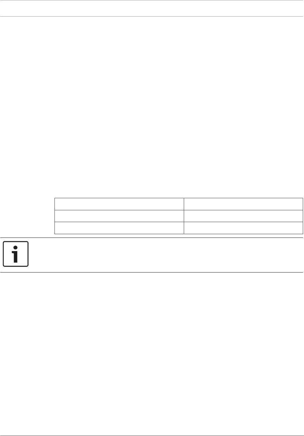
236 en | SDI2 modules Control Panel
2017.03 | 03 | F.01U.323.389 Program Entry Guide Bosch Security Systems, Inc.
RPS Menu Location
SDI2 > B42x IP Communicator > Module Hostname
14.3.16 Unit Description
Default: Blank
Selections: Up to twenty alphanumeric characters.
This parameter describes the B42xmodule (location, attributes, etc.).
The description can be programmed with up to twenty alphanumeric characters, including: A
to Z, 0 to 9, ?, &, @, -, *, +, $, #, /
Characters not listed are invalid and cannot be used for text.
RPS Menu Location
SDI2 Modules > IP Communicator > Unit Description.
14.3.17 TCP/UDP Port Number
Default: 7700
Selections: 0 - 65535
This parameter sets the local port number that the IP communicator listens to in-coming
network traffic. It also uses this port for outgoing communications.
The TCP/UDP Port is typically left at the default, 7700, for control panel communications with
a central station receiver, RPS, automation, or Remote Security Control (RSC).
Port numbers are categorized into three ranges:
System ports 0-1023
User ports 1024-49151
Dynamic or private ports 49152-65535
Notice!
Limit unwanted traffic, choose a port number greater than 1023
In order reduce the risk of unwanted network traffic interfering with control panel IP
communications, select a port number above 1023.
RPS Menu Location
SDI2 Modules > IP Communicator > TCP/UDP Port Number
14.3.18 TCP Keep Alive Time
Default: 45
Selections: 0 - 65 (seconds)
This parameter sets the time in seconds between TCP keep-alive transmissions to verify that
an idle connection is still active.
The parameter has no effect on B450 Plug-in Communicator Interface operation.
RPS Menu Location
SDI2 > B42x IP Communicator > TCP keep alive time
14.3.19 IPv4 Test Address
Default: 8.8.8.8
Selections: IPv4 address or Domain Name
The default test address works for most networks.
The control panel uses the IP communicator to ping the IPv4 Test Address to verify the
integrity of the network and the network configuration settings.

Control Panel SDI2 modules | en 237
Bosch Security Systems, Inc. Program Entry Guide 2017.03 | 03 | F.01U.323.389
RPS Menu Location
SDI2 > B42x IP Communicator > IPv4 Test Address
14.3.20 IPv6 Test Address
Default: 2001:4860:4860::8888
Selections: IPv6 address or Domain Name
The default test address works for most networks.
This parameter is only available when IPv6 Mode is set to Yes.
The control panel uses the IP communicator to ping the IPv4 Test Address to verify the
integrity of the network and the network configuration settings.
Further information
IP Address and Domain Name formats, page 254
RPS Menu Location
SDI2 > B42x IP Communicator > IPv6 test address
14.3.21 Web and Automation Security
Default: Enable
Selections:
– Disable - enhanced security is not applied.
– Enable - enhanced security is applied.
Set this parameter to Enable for enhanced security for Automation and B42x Web Access.
When enabled, HTTPS is applied to B42x Web Access changing the default value of the
HTTP Port Number, page 234 parameter. This setting also enables TLS Security for Automation.
RPS Menu Location
SDI2 > IP Communicator > Web and Automation Security
14.3.22 Alternate IPv4 DNS server IP address
Default: 0.0.0.0
Selections: 0.0.0.0 to 255.255.255.255
This parameter provides an alternate IPv4 DNS server IP address.
If the IP communicator fails to obtain an address from the primary server, it tries the alternate
DNS server.
Further information
IP Address and Domain Name formats, page 254
RPS Menu Location
SDI2 > B42x IP Communicator > Alternate IPv4 DNS server IP address
14.3.23 Alternate IPv6 DNS server IP address
Default: ::
Selections: 0000:0000:0000:0000:0000:0000:0000:0000 to
FFFF:FFFF:FFFF:FFFF:FFFF:FFFF:FFFF:FFFF
This parameter provides an alternate IPv6 DNS server IP address.
The Alternate IPv6 Domain Name Server (DNS) address has a hexadecimal notation, which
consists of the eight groups of the address expressed separately in hexadecimal and
separated by colons. Each group has a value between 0000-FFFF.
When this is defined through the DHCP service, leave the default value. If the module fails to
obtain an address from the primary server, the Alternate IPV6 DNS server is used, if specified.
The module can use the Alternate IPv6 DNS server only when the Primary address is not the
default address.
238 en | SDI2 modules Control Panel
2017.03 | 03 | F.01U.323.389 Program Entry Guide Bosch Security Systems, Inc.
Further information
IP Address and Domain Name formats, page 254
RPS Menu Location
SDI2 > B42x IP Communicator > Alternate IPv6 DNS server IP address
14.4 B450 cellular
14.4.1 Inbound SMS
Notice!
Important configuration information for cellular communication
Refer to Configuring for Cellular Service, page 252 for an overview and configuration
information.
Default: Yes
Selections:
Yes - Enabled
No - Disabled
This parameter enables an RPS user to start a control panel initiated download with an SMS
message.
RPS menu location
SDI2 modules > IP Communicator > B450 Cellular > Inbound SMS
14.4.2 Session Keep Alive Period (min.)
Notice!
Important configuration information for cellular communication
Refer to Configuring for Cellular Service, page 252 for an overview and configuration
information.
Default: 0
Selections: 0 to 1000 (minutes)
– 0 - Disabled. Panel does not verify the connection is active.
– 1 to 1000 - Enabled. Panel verifies an active connection exists.
This parameter sets the length of time in minutes between session keep alive reports to verify
that an idle connection is still active. This parameter is pre-configured for optimal
performance. Leave at the default setting. Default settings should only be changed for high
security UL1610 commercial listed installations requiring low signal notification.
RPS menu location
SDI2 modules > IP Communicator > B450 Cellular > Session keep alive period
14.4.3 Inactivity Time Out (min.)
Notice!
Important configuration information for cellular communication
Refer to Configuring for Cellular Service, page 252 for an overview and configuration
information.
Control Panel SDI2 modules | en 239
Bosch Security Systems, Inc. Program Entry Guide 2017.03 | 03 | F.01U.323.389
Default: 0
Selections: 0 to 1000 (minutes)
– 0 - Disabled. Panel does not verify the connection is active.
– 1 to 1000 - Enabled. Panel verifies an active connection exists.
This parameter specifies the time before the control panel will disconnect a session with no
data traffic. This parameter is pre-configured for optimal performance. Leave at the default
setting. Default settings should only be changed for high security UL1610 commercial listed
installations requiring low signal notification.
RPS menu location
SDI2 modules > IP Communicator > B450 Cellular > Inbound SMS
14.4.4 Reporting Delay for Low Signal Strength (sec.)
Notice!
Important configuration information for cellular communication
Refer to Configuring for Cellular Service, page 252 for an overview and configuration
information.
Default: 0
Selections: 0-3600 (seconds)
– 0 - Disabled.
– 1 to 3600 - seconds of delay before Cellular Low Signal event.
Notice!
UL Requirement
To meet UL requirements, the entry for this parameter should not exceed 200 seconds.
The control panel creates a Cellular Low Signal event when the signal strength is below the
"unacceptable" threshold (indicated by the red LED) for the number of seconds specified in
this Reporting Delay for Low Signal Strength parameter. (Low signal is defined as 80% of the
measurements taken during the time period are below the threshold).
The control panel creates a Cellular Low Signal Restoral event when the signal strength is
above the "good" threshold (indicated by the green LED) for the number of seconds specified
in this Reporting Delay for Low Signal Strength parameter. (Good signal is defined as 80% of
the measurements taken during the time period are above the threshold).
RPS menu location
SDI2 modules > IP Communicator > B450 Cellular > Reporting delay for low signal strength
14.4.5 Reporting Delay for Single Tower (sec.)
Notice!
Important configuration information for cellular communication
Refer to Configuring for Cellular Service, page 252 for an overview and configuration
information.
Default: 1800
Selections: 0-3600 (seconds)
– 0 - Disabled.
– 1 to 3600 (seconds)
240 en | SDI2 modules Control Panel
2017.03 | 03 | F.01U.323.389 Program Entry Guide Bosch Security Systems, Inc.
Leave this parameter at the default setting unless otherwise instructed by a Bosch Security
Systems, Inc. representative.
The control panel creates a Single Tower event when only a single tower has been available for
the number of seconds set at this parameter.
The control panel creates a Single Tower restoral event when two or more towers are available
for the number of seconds set at this parameter.
RPS menu location
SDI2 modules > IP Communicator > B450 Cellular > Reporting delay for single tower
14.4.6 Reporting Delay for No Towers (sec.)
Notice!
Important configuration information for cellular communication
Refer to Configuring for Cellular Service, page 252 for an overview and configuration
information.
Default: 0
Selections: 0-3600 (seconds)
– 0 - Disabled.
– 1 to 3600 - Enabled.
When there are no towers present the control panel starts two timers, one for a
NoTowersevent, one for a NoIPAddress event. The control panel uses the duration set by
this ReportingDelayforNoTowerparameter for both timers. If the cellular plug-in module
does not find a tower before the end of the delay, the control panel creates a NoTowersevent
and a NoIPAddressevent at the same time.
The control panel creates a NoTowerrestoral event when one or more towers are available for
the duration set by this ReportingDelayforNoTowerparameter.
The contro panel creates a NoIPAddressrestoralevent when the cellular plug-in module
successfully registers with one or more towers and receives an IP address.
Notice!
When one or more towers are available, 60 second delay for NoIPAddressevent
If the cellular plug-in module successfully registers with one or more towers, but does not
receive an IP address within 60 seconds, the control panel creates a NoIPAddressevent.
RPS menu location
SDI2 modules > IP Communicator > B450 Cellular > Reporting delay for no towers
14.4.7 Outgoing SMS Length
Notice!
Important configuration information for cellular communication
Refer to Configuring for Cellular Service, page 252 for an overview and configuration
information.
Default: 0
Selections: 0-3600 (seconds)
– 0 - Disabled.
– 1 to 3600 - Enabled.
Control Panel SDI2 modules | en 241
Bosch Security Systems, Inc. Program Entry Guide 2017.03 | 03 | F.01U.323.389
When there are no towers present the control panel starts two timers, one for a
NoTowersevent, one for a NoIPAddress event. The control panel uses the duration set by
this ReportingDelayforNoTowerparameter for both timers. If the cellular plug-in module
does not find a tower before the end of the delay, the control panel creates a NoTowersevent
and a NoIPAddressevent at the same time.
The control panel creates a NoTowerrestoral event when one or more towers are available for
the duration set by this ReportingDelayforNoTowerparameter.
The contro panel creates a NoIPAddressrestoralevent when the cellular plug-in module
successfully registers with one or more towers and receives an IP address.
Notice!
When one or more towers are available, 60 second delay for NoIPAddressevent
If the cellular plug-in module successfully registers with one or more towers, but does not
receive an IP address within 60 seconds, the control panel creates a NoIPAddressevent.
RPS menu location
SDI2 modules > IP Communicator > B450 Cellular > Reporting delay for no towers
14.4.8 SIM PIN
Notice!
Important configuration information for cellular communication
Refer to Configuring for Cellular Service, page 252 for an overview and configuration
information.
Default: Blank
Selections: 4-8 numbers
This is an optional parameter. This parameter is only necessary if the SIM card uses a PIN for
security.
The SIM PIN is hidden on the display and appears as asterisks (********) when entered. If an
invalid SIM PIN is entered, an event is logged in history. A report is sent only if the report
function is enabled. If no SIM PIN is required, you can leave the field blank.
RPS menu location
SDI2 modules > IP Communicator > B450 Cellular > SIM PIN
14.4.9 Network Access Point Name (APN)
Notice!
Important configuration information for cellular communication
Refer to Configuring for Cellular Service, page 252 for an overview and configuration
information.
Default: wyless.apn
Selections: 0-99 ASCII characters
This parameter sets the IP address for the network access point. Enter up to 99 alphanumeric
characters. The field is case sensitive.
RPS menu location
SDI2 modules > IP Communicator > B450 Cellular > Network access point name (APN)

242 en | SDI2 modules Control Panel
2017.03 | 03 | F.01U.323.389 Program Entry Guide Bosch Security Systems, Inc.
14.4.10 Network Access Point User Name
Notice!
Important configuration information for cellular communication
Refer to Configuring for Cellular Service, page 252 for an overview and configuration
information.
Default: Blank
Selections: 0-30 ASCII characters
This parameter specifies the user name for the Network Access Point.
Enter up to 30 alphanumeric characters. The field is case sensitive.
RPS menu location
SDI2 modules > IP Communicator > B450 Cellular > Network access point user name
14.4.11 Network Access Point Password
Notice!
Important configuration information for cellular communication
Refer to Configuring for Cellular Service, page 252 for an overview and configuration
information.
Default: Blank
Selections: 0-30 ASCII characters
This parameter sets the password required to access the Network Access Point.
Enter up to 30 alpha-numeric characters. The password is case sensitive.
RPS menu location
SDI2 modules > IP Communicator > B450 Cellular > Network access point password
14.5 B520 aux power supply
The B520 Auxiliary Power Supply is a device that attaches to the SDI2 bus of the control
panel. It provides a supervised 12 Volt DC 2.5 Amp auxiliary power supply.
Each power supply might support 2 separate 12V nominal lead acid batteries with a capacity
of 7-18 Ah.
Settings
RPS supports the configuration of the Enclosure Tamper, page 230 on each of the Power
Supply modules.
Yes = Enable enclosure tamper, No = Disable enclosure tamper. Default setting is No.
RPS supports the configuration of the Module Enable, page 243 on each of the Power Supply
modules.
Yes = Enable module supervision, No = Disable module supervision. Default setting is No.
RPS supports the configuration of the One or Two Batteries, page 243 on each of the Power
Supply modules.
Switch Settings
Ref. Hardware Switch Settings > SDI2 Devices > B520 Power Supply switch settings, page 251

Control Panel SDI2 modules | en 243
Bosch Security Systems, Inc. Program Entry Guide 2017.03 | 03 | F.01U.323.389
14.5.1 Module Enable
Default: No
Selections: Yes or No
Yes Supervise the SDI2 module.
No Do not supervise the SDI2 module.
This parameter indicates to the control panel if the SDI2 module should be supervised.
RPS Menu Location
SD12 > B520 Power Supply > Module Enable
14.5.2 Module Enclosure Tamper
Default: No - Disable
Selections:
Yes - Enable enclosure tamper input
No - Disable enclosure tamper input
This parameter enables the enclosure tamper switch input on the SDI2 module.
When the input is enabled and connected to a Bosch ICP-EZTS tamper switch installed in the
module enclosure, the control panel can create a tamper event when the enclosure door is
opened, or when the enclosure is removed from the wall.
RPS Menu Location
SDI2 > B520 Aux Power Supply > Enclosure Tamper
14.5.3 One or Two Batteries
Default: One
Selections: One or Two
This parameter specifies if 1 or 2 backup batteries are installed with the Auxiliary Power
Supply module.
RPS Menu Location
SDI2 Modules > B520 Aux Power Supply > One or Two Batteries
14.6 Wireless Receiver
The SDI2 bus of the control panel supports the B820 Inovonics SDI2 Wireless Interface
Module. The B820 module provides the ability to use wireless key fobs, repeaters and points
with the control panel.
Capacity
The control panel supports two types of SDI2 wireless interface modules:
B810 RADION Wireless
B820 Inovonics Wireless
You can use only one wireless module at a time. All points, repeaters and key fobs must be the
same type.
RADION limits:
Keyfobs - 1000
Points - 504
Repeaters - 8
RPS displays a warning message when you reach these limits. To add another device of that
type, delete one or more of the existing devices.

244 en | SDI2 modules Control Panel
2017.03 | 03 | F.01U.323.389 Program Entry Guide Bosch Security Systems, Inc.
Notice!
Choose the type of wireless module before you add any points, users or repeaters to the
system. When you change wireless types, RPS resets all RF information to factory defaults. All
previously configured RF information is erased.
Settings
RPS supports the configuration of the Enclosure Tamper, page 230 on each of the Wireless
Receiver modules.
RPS supports the configuration of the global System (Repeater) Supervision Time, page 245 for
devices configured to report to the Wireless Receiver.
RPS supports the configuration of the Low Battery Resound, page 245 on each of the Wireless
Receiver modules.
Switch Settings
Refer to B810/B820 Hardware switch settings, page 248
14.6.1 Wireless Module Type
Default: B810 RADION Wireless
Selections:
– Unassigned
– B810 RADION Wireless
– B820 Inovonics Wireless
This parameter configures the system for either a RADION or an Inovonics wireless module.
Unassigned. You cannot use a wireless device. Wireless is not a valid selection for the Point
Source parameter for any point. You cannot enroll RF Keyfobs for any user.
B820 Inovonics Wireless limits:
Devices - 350 (not including repeaters)
Repeaters - 4
You can assign Inovonics wireless devices to points.
You can assign Inovonicskeyfobs to users.
B810 RADION Wireless limits:
Keyfobs - 1000
Points - 504 (valid point numbers: 9 to 96)
Repeaters - 8
When these limits are reached, RPS shows a warning message. To add another device of that
type, delete one or more of the existing devices.
RPS Menu Location
SDI2 Modules > Wireless Receiver > Wireless Module Type
14.6.2 Module Enclosure Tamper
Default: No - Disable
Selections:
Yes - Enable enclosure tamper input
No - Disable enclosure tamper input
This parameter enables the enclosure tamper switch input on the SDI2 module.
When the input is enabled and connected to a Bosch ICP-EZTS tamper switch installed in the
module enclosure, the control panel can create a tamper event when the enclosure door is
opened, or when the enclosure is removed from the wall.
Control Panel SDI2 modules | en 245
Bosch Security Systems, Inc. Program Entry Guide 2017.03 | 03 | F.01U.323.389
RPS Menu Location
SDI2 > Wireless Receiver > Enclosure Tamper
14.6.3 System (Repeater) Supervision Time
Default: 12 hours
Selections:
– None - Disable wireless repeater supervision.
– 4, 12, 24, 48, 72 hours
This parameter sets the supervision time for all configured wireless repeaters. If the wireless
receiver does not hear from a repeater within the number of hours set by this parameter, the
control panel creates a missing repeater event.
Notice!
Wireless Point Supervision Time
Configure the wireless supervision time for non-fire points using the parameter Point
Profiles / Wireless Point Supervision Time, page 194. The wireless point supervision time for
fire points is fixed at 4 hours.
Notice!
Wireless Keyfob Supervision Time
Enable or disable wireless supervision time for wireless keyfobs using the parameter User
Assignments / Supervised, page 143. When supervision is enabled, the wireless keyfob
supervision time is fixed at 4 hours.
RPS Menu Location
SDI2 > Wireless Receiver > System Supervision Time
14.6.4 Low Battery Resound
Default: Never Resound
Selections: Never Resound, 4 hours, 24 hours
This parameter is global for all non-fire points. The control panel automatically fixes the Low
Battery Resound at 24 hours for fire points.
RPS Menu Location
SDI2 Modules > Wireless Receiver > Low Battery Resound
14.6.5 Enable Jamming Detection
Default: Yes
Selections: Yes / No
This parameter setting turns on or off the reporting of interference to the control panel.
The B810 RADION wireless module detects RF jamming (interference) when it is present. You
can use jamming Detection can be disabled for the B810 RADION Wireless module. The B820
Inovonics Wireless module also detects RF jamming (interference) when it is present.
Jamming Detection annot be disabled for the B820 Inovonics Wireless module.
RPS Menu Location
SDI2 Modules > Wireless Receiver > Enable Jamming Detection
14.7 Wireless Repeater
The wireless repeater modules are independent of the SDI2 bus. You can use a wireless
repeater to extend the range of the B820 Inovonics SDI2 Wireless Interface Module for an
installation site.

246 en | SDI2 modules Control Panel
2017.03 | 03 | F.01U.323.389 Program Entry Guide Bosch Security Systems, Inc.
Capacity
The control panel supports two types of SDI2 wireless interface modules:
– B810 RADION Wireless
– B820 Inovonics Wireless
The type of wireless repeater must match the type of receiver. Choose the type of wireless
receiver before you configure any repeaters. The control panel supports up to 8 repeaters
simultaneously. All repeaters must be the same type.
Settings
You can configure the Enclosure Tamper on each of the wireless repeater modules.
Yes (default) = Enable enclosure tamper
No = Disable enclosure tamper.
You can configure the RFID for each of the Wireless Repeater modules.
There are no hardware switches on a wireless repeater. The location of the RFID within the
configuration table determines the wireless repeater number.
Notes
Even though RPS lists the Wireless Repeater configuration under the SDI2 Modules heading,
wireless repeaters are not physically connected to the SDI2 bus. You must configure a
wireless interface module as part of the system.
14.7.1 Module Enclosure Tamper
Default: No - Disable
Selections:
Yes - Enable enclosure tamper input
No - Disable enclosure tamper input
This parameter enables the enclosure tamper switch input on the SDI2 module.
When the input is enabled and connected to a Bosch ICP-EZTS tamper switch installed in the
module enclosure, the control panel can create a tamper event when the enclosure door is
opened, or when the enclosure is removed from the wall.
RPS Menu Location
SDI2 > Wireless Repeater > Enclosure Tamper
14.7.2 RADION RFID (B810)
Default: 0
Selection: 0, 11 - 167772156
This parameter provides a unique way for the Wireless Receiver and Wireless Repeaters to
identify what device is transmitting.
The Radio Frequency device Identification number (RFID) is a unique number assigned to a
wireless device at the factory. Since the Wireless Repeater is a receiver as well as a
transmitter it also is assigned an RFID so that the Wireless Receiver can determine what
Repeater is transmitting.
This RFID number is located on the label that is affixed to the device. The label location might
differ for each RF device.
RADION supports up to 1000 keyfobs. Keyfobs can be assigned to any user # between 1-2000,
but cannot exceed more than 1000 devices in total.
RPS Menu Location
SDI2 Modules > Wireless Repeater > RFID (B810 RADION Wireless)
14.7.3 Inovonics RFID (B820)
Default: N/A
Range: 0 - 99999999

Control Panel SDI2 modules | en 247
Bosch Security Systems, Inc. Program Entry Guide 2017.03 | 03 | F.01U.323.389
This parameter provides a unique way for the Wireless Receiver and Wireless Repeaters to
identify what device is transmitting.
The RFID (Radio Frequency device Identification number) is a unique number assigned to a
wireless device at the factory. Since the Wireless Repeater is a receiver as well as a
transmitter it also is assigned an RFID so that the Wireless Receiver can determine what
Repeater is transmitting.
This RFID number is located on the label that is affixed to the device. The label location might
differ for each RF device.
RPS Menu Location
SDI2 Modules > Wireless Repeater > RFID (B820 Inovonics Wireless)

248 en | Hardware switch settings Control Panel
2017.03 | 03 | F.01U.323.389 Program Entry Guide Bosch Security Systems, Inc.
15 Hardware switch settings
15.1 Keypad address
B91x Basic Keypad address switch settings
Address Switches
1 23456
1 ON OFF OFF OFF OFF OFF
2 OFF ON OFF OFF OFF OFF
3 ON ON OFF OFF OFF OFF
4 OFF OFF ON OFF OFF OFF
5 ON OFF ON OFF OFF OFF
6 OFF ON ON OFF OFF OFF
7 ON ON ON OFF OFF OFF
8 OFF OFF OFF ON OFF OFF
9 ON OFF OFF ON OFF OFF
10 OFF ON OFF ON OFF OFF
11 ON ON OFF ON OFF OFF
12 OFF OFF ON ON OFF OFF
13 ON OFF ON ON OFF OFF
14 OFF ON ON ON OFF OFF
15 ON ON ON ON OFF OFF
16 OFF OFF OFF OFF ON OFF
17 ON OFF OFF OFF ON OFF
18 OFF ON OFF OFF ON OFF
19 ON ON OFF OFF ON OFF
20 OFF OFF ON OFF ON OFF
21 ON OFF ON OFF ON OFF
22 OFF ON ON OFF ON OFF
23 ON ON ON OFF ON OFF
24 OFF OFF OFF ON ON OFF
25 ON OFF OFF ON ON OFF
26 OFF ON OFF ON ON OFF
27 ON ON OFF ON ON OFF
28 OFF OFF ON ON ON OFF
29 ON OFF ON ON ON OFF
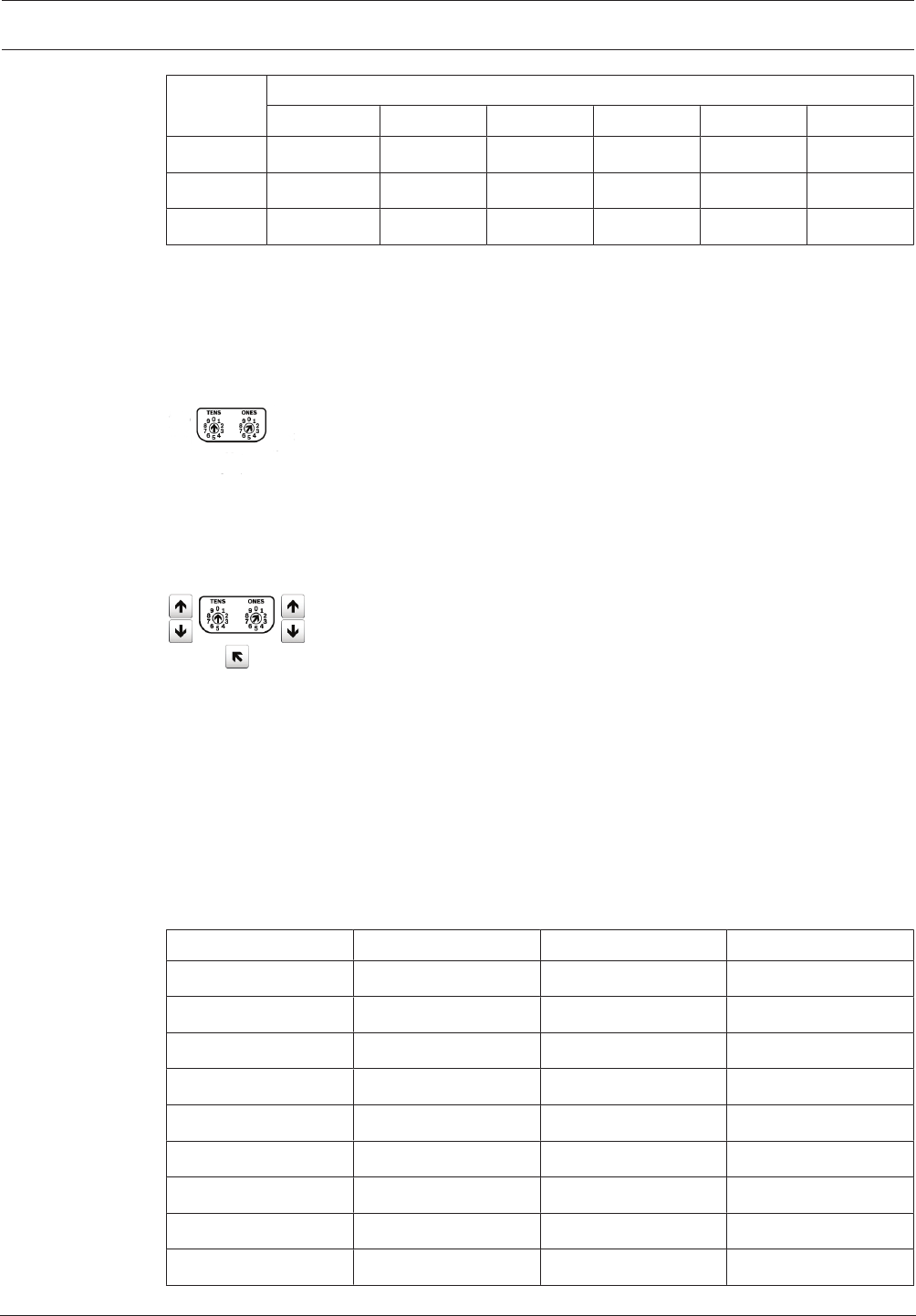
Control Panel Hardware switch settings | en 249
Bosch Security Systems, Inc. Program Entry Guide 2017.03 | 03 | F.01U.323.389
Address Switches
1 23456
30 OFF ON ON ON ON OFF
31 ON ON ON ON ON OFF
32 OFF OFF OFF OFF OFF ON
B92x Two-line Keypad / B93x ATM Style Keypad address switch settings
Set the address switches per the control panel configuration. If multiple SDI2 keypads reside
on the same system, each SDI2 keypad must have a unique address. For single-digit addresses
1 through 9, set the tens switch to 0. The figure below shows the address switch setting for
address 1.
B94x Touch Screen Keypad address switch settings
To set the address, use the up and down arrows on the right of the switches image to change
the ones digit, and the arrows on the left to change the tens digit. Press the diagonal arrow
under the switches to save the setting and return to the power up screen.
15.2 B208 Octo-input Module switch settings
This table describes the relationship between the module switch settings and the point
address range that corresponds to the setting. The values of point range listed in this table
references back to POINTS > Point Assignments.
The B6512 supports up to 9 B208 Octo-input modules.
The B5512 supports up to 4 modules.
The B4512 supports up to 2 modules.
The B3512 does not support the B208 module.
Terminate unused B208 inputs with an EOL resistor.
B208 address number B6512 point numbers B5512 point numbers B4512 point numbers
1 11 - 18 11 - 18 11 - 18
2 21 - 28 21 - 28 21 - 28
3 31 - 38 31 - 38
4 41 - 48 41 - 48
5 51 - 58
6 61 - 68
7 71 - 78
8 81 - 88
9 91 - 96

250 en | Hardware switch settings Control Panel
2017.03 | 03 | F.01U.323.389 Program Entry Guide Bosch Security Systems, Inc.
15.3 B308 Octo-output Module switch settings
This table describes the relationship between the module switch settings and the output
number range that corresponds to the setting.
The 65512 supports up to 9 B308 Octo-output modules.
The B5512 supports up to 5 modules.
The B4512 supports up to 3 modules.
The B3512 does not support the B308 module.
B308 address number B6512 output
numbers
B5512 output
numbers
B4512 output
numbers
1 11 - 18 11 - 18 11 - 18
2 21 - 28 21 - 28 21 - 28
3 31 - 38 31 - 38 31 - 38
4 41 - 48 41 - 48
5 51 - 58 51 - 58
5 51 - 58
6 61 - 68
7 71 - 78
8 81 - 88
15.4 B426 Ethernet Communication Module switch settings
This table describes the relationship between the module switch settings and type of control
panel communication that corresponds to the setting.
B426 switch setting Address Bus type Function
0 Local configuration
setting (default
setting)
1 1 (173) SDI2 Automation or RPS
reporting
15.5 B450 Cellular Module switch settings
This table describes the relationship between the module switch settings and type of control
panel communication that corresponds to the setting.
B450 switch setting Address Bus type Function
0 Local configuration
setting (default
setting)
1 1 (173) SDI2 Automation or RPS
reporting

Control Panel Hardware switch settings | en 251
Bosch Security Systems, Inc. Program Entry Guide 2017.03 | 03 | F.01U.323.389
15.6 B520 Power Supply switch settings
The rotary address switch range for the B520 Power Supply is between 1 and 4 for the B5512,
between 1 and 2 for the B4512, and 1 for the B3512 control panels. Address ranges 00 and
05-99 are not valid on the SDI2 device bus. The factory default setting is 01. When using more
than one power supply, assign each power supply a different switch setting.
Valid B520 switch settings
01
02
03
04
15.7 B810 RADION wireless receiver switch settings
B810 and B820 address switches provide a single-digit setting for the module’s address. The
module uses address 1. Addresses 0 and 2 through 9 are invalid.
15.8 B820 Inovonics wireless receiver switch settings
The B820 Inovonics address switches provide a single-digit setting for the module’s address.
The module uses addresses 1 through 4. Addresses 0 and 5 through 9 are invalid.
Only address 1 is valid for these control panels.
15.9 B901 Access Module switch settings
Two address switches determine the address for the B901 Access Control Module. The
control panel uses the address for communications.
Use a slotted screwdriver to set the address switches.
Address Designation
0,0 Disabled
0,1 to 0,4 Doors 1 through 4
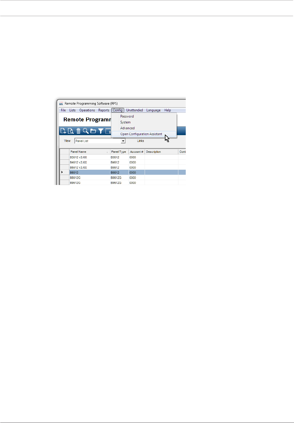
252 en | Configuring for Cellular Service Control Panel
2017.03 | 03 | F.01U.323.389 Program Entry Guide Bosch Security Systems, Inc.
16 Configuring for Cellular Service
Sign-up for Bosch Cellular Service first
Before you can utilize cellular communication for reporting, personal notifications, RPS
connections, or RSC connections you need to register for Bosch Cellular Service at the Bosch
Installer Services Portal, https://installerservices.boschsecurity.com/.
Configure RPS for cellular service
Configuring RPS for cellular service is quick and easy using the Configuration Assistant. Click
Config to open the Configuration menu. Select OpenConfigurationAssistant.
Figure16.1: Configuration Assistant
If you choose not to use not to use the Configuration Assistant, follow the steps below to
configure RPS for cellular service.
1. Click Config to open the Configuration menu. Click System.
2. Click the Connectivity tab.
3. Click Cellular.
4. If you will connect from the internet to the panel using cellular IP over a PPTP VPN (a
login is provided with Bosch Cellular), click the VPN tab. This one-time setup automates
the PPTP VPN login and connection from the Connect window in RPS.
The VPN client (or Windows VPN) must be setup on your PC before RPS can use it. This
setup is not required if your network is configured for always-on IPSec VPN connection to
the network provider.
For instructions on setting up Windows VPN, refer to the Bosch Cellular Services User
Guide located at http://www.conettix.com/Downloads.aspx.
Configure the control panel account for cellular service
Configuring a control panel account for cellular service is quick and easy using the Account
Assistant.
In the Panel List, right-click the panel account you want to configure for cellular service, then
click OpenAccountAssistant.
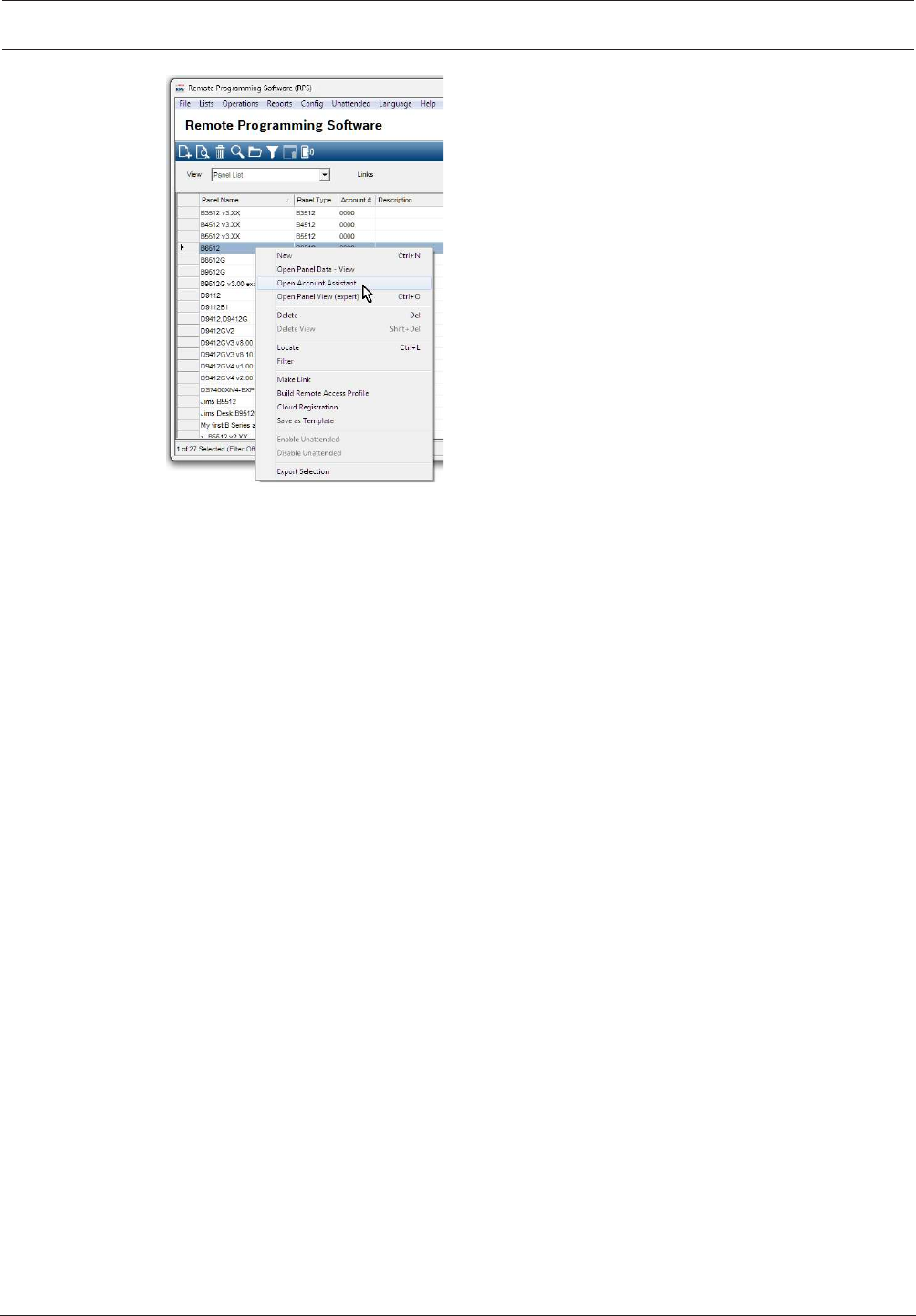
Control Panel Configuring for Cellular Service | en 253
Bosch Security Systems, Inc. Program Entry Guide 2017.03 | 03 | F.01U.323.389
Figure16.2: Open Account Assistant
If you choose not to use not to use the Account Assistant, follow the steps below to configure
a control panel account for cellular service.
1. In the Panel List, right-click the panel account you want to configure for cellular service,
then click OpenPanelData - View.
2. Click the Cellular tab.
3. Press F1 to open the help for the Cellular tab.
4. Follow the instructions to enter information in the Cellular Connectivity fields. RPS uses
the SIM or radio MEID number to retrieve and store the assigned IP address, phone
number and assigned plan.
5. Click Show Plans, and then click Plan Help. Select an appropriate plan to avoid overage
fees.
6. Click OK when you're finished. You're back to the Panel List.
7. To set panel parameters, in the Panel List, right-click the panel account you clicked in
step 1, then click OpenPanelView.
8. Panel Wide Parameters > Cellular Plug-in Module, page 36: leave the parameters here at
their defaults. Only change for UL1610 commercial listed installations requiring low signal
notification.
9. Panel Wide Parameters > Communicator, overview, page 58 > Primary Destination Device
(Backup Destination Device): to send reports for a Route Group via a cellular
communicator, select a (Plug-in) Cellular Destination as the Primary (or Backup)
Destination.
10. Panel Wide Parameters > Enhanced Communication, page 62: set reporting Destinations,
and polling/supervision settings here. Be sure cellular polling rates follow recommended
settings and align with your cellular plan.
11. Panel Wide Parameters > Personal Notification > Personal Notification Destinations, page
84: set phone numbers for SMS messages, email addresses for email messages. Set
Method to Plug in Cellular SMS, Bus Device Cellular SMS, Plug in Cellular Email, or Bus
Device Email.

254 en | IP Address and Domain Name formats Control Panel
2017.03 | 03 | F.01U.323.389 Program Entry Guide Bosch Security Systems, Inc.
17 IP Address and Domain Name formats
IPv4 Address Format
IPv4 addresses are in ASCII decimal format, xxx.xxx.xxx.xxx (xxx = 0 to 255). The four octets
(xxx) of the address are separated by periods.
Correct: 12.3.145.251
Incorrect: C.17.91.FB
IPv6 Address Format
IPv6 addresses consist of eight groups of 4 hexadecimal digits separated by colons,
xxxx:xxxx:xxxx:xxxx:xxxx:xxxx:xxxx:xxxx, x = 0 to F.
Fully Qualified Domain Name Format
The fully qualified domain name defines the exact address of a device in the Domain Name
System (DNS) hierarchy. This includes the unique hostname of the device and the subnet on
which the device is located, separated by periods.
Example: receiver01.your-alarm-company.com
Each label within the name must comply with RFC-921, "Domain Name System
Implementation Schedule".
Only the letters (A-Z), numbers (0-9), and the minus sign (-) are allowed in the text labels in
the fully qualified domain name.
The period (.) is only allowed to delimit text labels that comprise the fully qualified domain
name.
Before entering a fully qualified domain name, be sure the device being addressed has its
name properly registered with the DNS servers available to the IP communicator. This can be
verified using a ping tool.
Additional Information
Information on Hostnames and fully qualified Domain Name formats can be found on the "The
Internet Engineering Task Force (IETF)" website http://www.ietf.org/

Bosch Security Systems, Inc.
130 Perinton Parkway
Fairport, NY 14450
USA
www.boschsecurity.com
© Bosch Security Systems, Inc., 2017
Bosch Sicherheitssysteme GmbH
Robert-Bosch-Ring 5
85630 Grasbrunn
Germany
