Bosch B9512/B8512 UL Installation Guide En Us B9512G B8512G Manual 18617908491
User Manual: Bosch en-us B8512G Control Panels
Open the PDF directly: View PDF ![]() .
.
Page Count: 44
- Title Page
- Introduction
- System overview
- Control panel installation
- Power supply
- On-board outputs
- Control panel board overview
- System wiring diagrams
- B925F Fire Keypad operating instructions
- B926F Fire Keypad operating instructions
- D1255RB operating instructions
- D1256RB operating instructions
- Specifications
- Back Page
- Blank Page
- Blank Page
Control Panels
B9512G/B8512G (B9512G-E/B8512G-E)
en UL Installation Guide
Introduction
This section includes an introduction to documents for this product and other document-
related instructions.
About documentation
This document contains instructions for a trained installer to properly install, configure, and
operate this control panel, and optional peripheral devices. Review this document before
beginning the installation to determine the hardware and wiring requirements for the features
used.
(Bosch Security Systems, Inc. recommends that installers follow good wiring practices such as
those descibed in NFPA 731, Standard for the Installation of Electronics Premises Security
Systems.)
Throughout this document, the words “control panel” refer to all control panels covered by
this document (B9512G/B8512G/B9512G-E/B8512G-E).
Notifications
This document uses Notices, Cautions, and Warnings to draw your attention to important
information.
Notice!
These include important notes for successful operation and programming of equipment, or
indicate a risk of damage to the equipment or environment.
!
Caution!
These indicate a hazardous situation which, if not avoided, could result in minor or moderate
injury.
!
Warning!
These indicate a hazardous situation which, if not avoided, could result in death or serious
injury.
Copyright
This document is the intellectual property of Bosch Security Systems, Inc. and is protected by
copyright. All rights reserved.
Trademarks
All hardware and software product names used in this document are likely to be registered
trademarks and must be treated accordingly.
Related documentation
Control panel documents
Control Panels (B9512G/B8512G) Release Notes *
Control Panels (B9512G/B8512G) Installation and System Reference Guide (P/N: F01U303996)+
Control Panels (B9512G/B8512G/B5512/B4512/B3512) Owner’s Manual (English) (P/N:
F01U307371)* +
Control Panels (B9512G/B8512G) Program Entry Guide (P/N: F01U303998)+
Control Panels (B9512G/B8512G) UL Installation Guide+ (this document) (P/N: F01U304001)*
+
1
1.1
1.1.1
Control Panels Introduction | en 3
Bosch Security Systems, Inc. UL Installation Guide 2016.05 | 05 | F.01U.304.001

Control Panels (B9512G/B8512G) SIA Quick Reference Guide (P/N: F01U304000)* +
Control Panels (B9512G/B8512G/B6512/B5512/B4512/B3512) ULC Installation Guide (P/N:
F01U321698)
*Shipped with the control panel.
+Located on the documentation CD shipped with the control panel.
Keypad documents
Basic Keypad (B915) Installation Guide (P/N: F01U297873)*
Two-line Alphanumeric Keypad (B920) Installation Guide (P/N: F01U265450)*
Fire Keypads (B925F/B926F) Installation Guide (P/N: F01U305193)*
Two-line Capacitive Keypad with Inputs (B921C) Installation Guide (P/N: F01U297887)*
ATM Style Alphanumeric Keypad (B930) Installation Guide (P/N: F01U265451)*
Touch Screen Keypad (B942/B942W) Installation Guide (P/N: F01U294527)*
*Shipped with the keypad.
Optional module documents
Octo-input Module (B208) Installation and Operation Guide (P/N: F01U265456)*
POPEX Module (B299) Installation Guide (P/N: F01U300043)*
Octo-output Module (B308) Installation and Operation Guide (P/N: F01U265458)*
Conettix Ethernet Communication Module (B426) Installation and Operation Guide (P/N:
F01U281208)* +
Plug-in Telephone Communicator (B430) Installation Guide Installation Guide (P/N:
F01U265454)*
Conettix Plug-in Cellular Communicator (B440) Installation and Operation Guide (P/N:
F01U265455)*
Conettix Plug-in CDMA Cellular Communicator (B441) Installation and Operation Guide (P/N:
F01U282233)*
Conettix Plug-in GPRS Cellular Communicator (B442) Installation and Operation Guide (P/N:
F01U283180)*
Conettix Plug-in HSPA+ Cellular Communicator (B443) Installation and Operation Guide (P/N:
F01U283181)*
Conettix Plug-in Communicator Interface (B450) Installation and Operation Guide (P/N:
F01U300740)* +
Auxiliary Power Supply (B520) Installation and Operation Guide (P/N: F01U265445)*
Retrofit ZONEX Module (B600) Installation Guide (P/N: F01U300237)
RADION receiver SD (B810) Installation Guide (P/N: F01U261834)*
SDI2 Inovonics Interface Module (B820) Installation Guide (P/N: F01U265460)*
Access Control Module (B901) Installation Guide (P:/N: F01U300416)
Dual Class B Initiating Module (D125B) Installation Instructions (P/N: F01U036340)
4en | Introduction Control Panels
2016.05 | 05 | F.01U.304.001 UL Installation Guide Bosch Security Systems, Inc.
Multiplex Bus Interface (D8125MUX) Operation and Installation Guide (P/N: F01U034973)
OctoPOPIT Module (D8128D) Installation Guide (P/N: F01U070537)
Access Control Interface Module (D9210C) Installation and Operation Guide (P/N:
F01U215232)
*Shipped with the module.
+Located on the documentation CD shipped with the module.
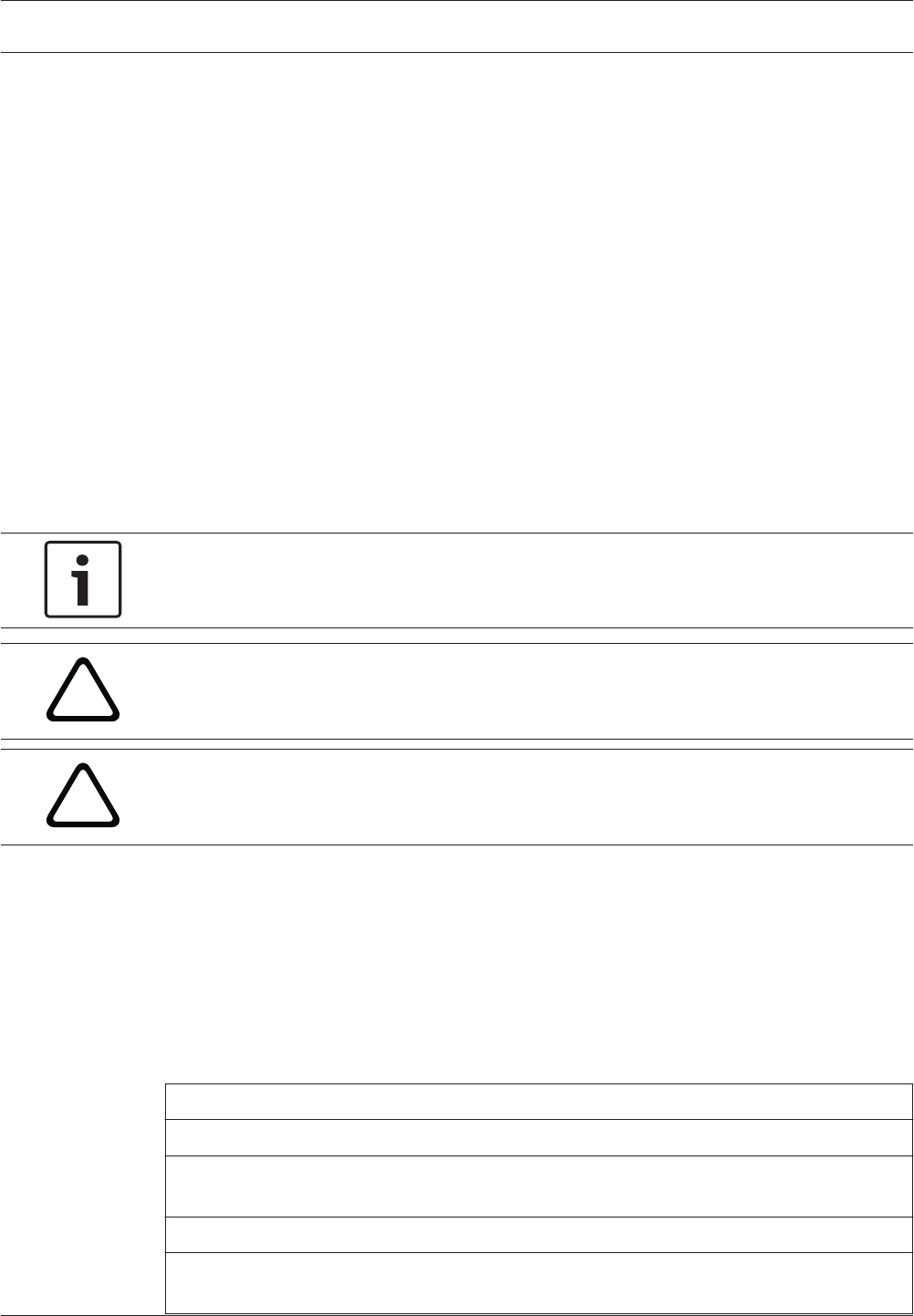
Bosch Security Systems, Inc. product manufacturing dates
Use the serial number located on the product label and refer to the Bosch Security Systems,
Inc. website at http://www.boschsecurity.com/datecodes/.
The following image shows an example of a product label and highlights where to find the
manufacturing date within the serial number.
1.2
Control Panels Introduction | en 5
Bosch Security Systems, Inc. UL Installation Guide 2016.05 | 05 | F.01U.304.001
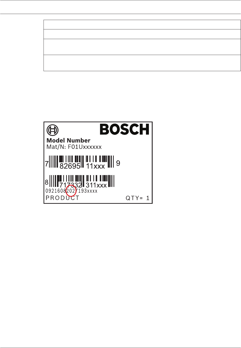
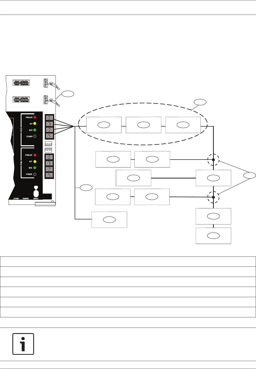
System overview
B430
Plug-in Tephone Communicator
provides a single
telephone RJ-45 connector
to allow communication
over telephone lines.
Control
Panel
On-board Points
1 to 8
B44x
Conettix Plug-In Cellular
Communicator allows
communciation over
a cellular network.
B208
Octo-input modules allow
the addition of up to 8
input devices.
B308
Octo-output modules allow
the addition of up to 8
output devices.
B520
Auxiliary Power Supply modules
expand power by connecting to
an SDI2 device bus or
other 12 volt devices.
B810
RADION receiver SDs
connect RADION wireless devices
to the control panel.
B820
SDI2 Inovonics Interface modules
interface with an Inovonics
wireless receiver.
B91x/B92x/B93x/B94x
Use keypads* to operate
the control panel by area.
B9512 control panels support up to 32 areas.
B8512 control panels support up to 8 areas.
Each area can have its own account number
or you can group together areas
with a common account number.
B450
Conettix Plug-In Communicator
Interface allows communciation
over a cellular network through
the SDI2 bus.
B426
The B426 provides off-board
communication over a network.
B299
POPEX modules provide
support for up to 100 POPIT
devices over a single
expansion loop.
B600
The ZONEX modules allows
the connection of ZONEX
expansion modules.
*Up to 8 of the keypads can be models D1260, D1257/D1257RB, D1256/D1256RB, or
D1255/D1255R/D1255RB on the SDI bus (SDIx configured as SDI).
2
6en | System overview Control Panels
2016.05 | 05 | F.01U.304.001 UL Installation Guide Bosch Security Systems, Inc.
Control panel installation
This section explains how to mount the control panel enclosure, how to mount the control
panel into the enclosure, and provides an overview of how to wire modules to the control
panel.
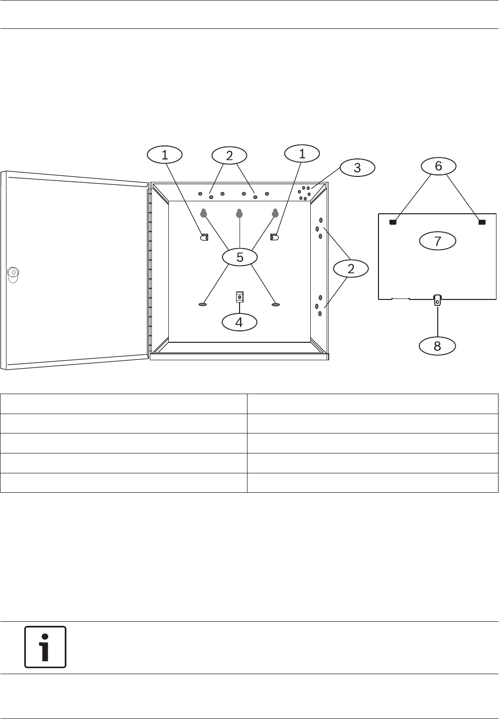
Enclosure overview
Before you begin, review the overview figure:
Figure 3.1: Enclosure and control panel mounting overview
Callout ᅳ Description Callout ᅳ Description
1 ᅳ Mounting skirt attachment hooks (2) 5 ᅳ Enclosure mounting holes (5)
2 ᅳ Module mounting three-hole pattern (4) 6 ᅳ Mounting skirt attachment holes (2)
3 ᅳTamper switch mounting location 7 ᅳ Back of the control panel mounting skirt
4 ᅳ Mounting skirt screw location (1) 8 ᅳ Mounting skirt screw tab
Install the enclosure
Refer to Enclosures to determine if the application requires a specific enclosure.
Installing the enclosure:
1. Remove any knockouts prior to installing the control panel.
2. Mount the enclosure in the desired location. Use all enclosure mounting holes. Refer to
the mounting instructions supplied with the selected enclosure.
3. Pull the wires into the enclosure.
4. Optionally install the supplied point label chart on the inside of the enclosure door.
Notice!
Electromagnetic interference (EMI) can cause problems on long wire runs.
3
3.1
Control Panels Control panel installation | en 7
Bosch Security Systems, Inc. UL Installation Guide 2016.05 | 05 | F.01U.304.001
Install the control panel
This section includes instructions to mount the control panel in the enclosure, connect earth
ground, and make other control panel connections.
Mount the control panel
Refer to the figure Enclosure overview, page 7.
Mounting the control panel:
1. Place the control panel over the inside back of the enclosure, aligning the large
rectangular openings of the mounting skirt with the enclosure mounting attachment
hooks. Slide the control panel down so that it hangs on the hooks.
2. Remove the tape from the #6 x 1/4-in screw in the mounting skirt screw tab on the
control panel. The screw passes through the mounting tab and into the skirt mounting
hole in the enclosure.
3. Tighten the screw to secure the control panel in the enclosure.
Notice!
Connect earth ground to the control panel before making any other connections.
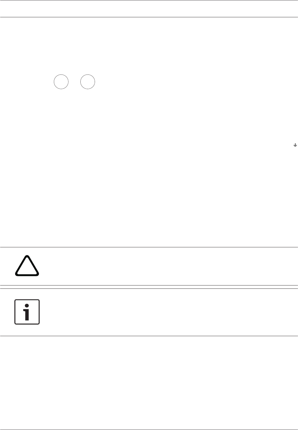
Connect earth ground
To help prevent damage from electrostatic discharges or other transient electrical surges,
connect the system to earth ground before making other connections. The icon (Terminal
10) indicates the earth ground terminal. Use a recommended earth ground reference, such as
a grounding rod or a cold water pipe. Make the connection using 14 AWG (1.8 mm) to 16 AWG
(1.5 mm) wire.
Notice!
Do not use telephone or electrical ground for the earth ground connection. Do not connect
other control panel terminals to earth ground.
!
Caution!
Avoid electrostatic discharge. Always touch the earth ground connection with the icon first,
before beginning work on the control panel.
Ground Fault Detect enable
To meet UL 864 requirements, enable Ground Fault Detect.
A ground fault is a circuit impedance to ground sufficient to result in the annunciation of a
trouble condition.
The control panel has a ground fault detection circuit that when enabled, detects ground
faults on Terminals 1 to 9 and 11 to 30.
If a ground fault condition occurs, the keypads annunciate a ground fault and the control panel
transmits a trouble message.
When the control panel recognizes that the ground fault condition is corrected, and remains
corrected for between 5 to 45 consecutive seconds, the control panel clears the fault from the
keypad display and sends a restoral report.
The control panel detects ground fault at ≤ 300 Ω.
3.2
3.2.1
3.2.2
3.2.3
8en | Control panel installation Control Panels
2016.05 | 05 | F.01U.304.001 UL Installation Guide Bosch Security Systems, Inc.

Enable Ground Fault Detect
To enable fault detection, use RPS. Refer to RPS Help.
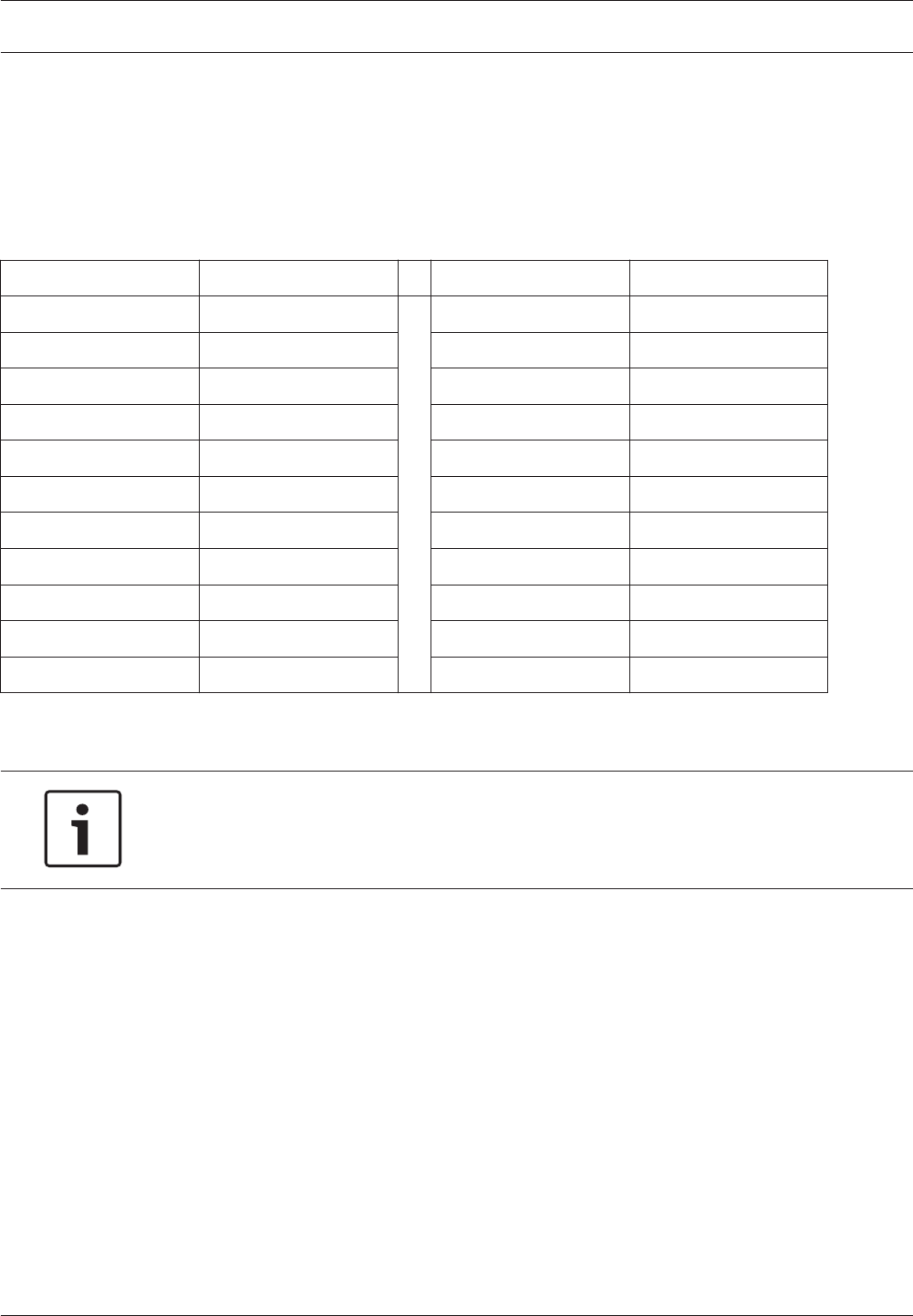
Ground fault detection troubleshooting
Measure earth ground (Terminal 10) and common (Terminal 9) to determine whether the
control panel has the necessary -2.1 V decay to 0.
Measuring and comparing voltage for ground fault detection:
1. Set your digital voltmeter (DVM) to measure VDC.
2. Connect the red DVM lead to control panel Terminal 10, and the black DVM lead to
Terminal 9.
3. Compare this voltage to the following table:
Control panel voltage at Terminals 9 and 10) Terminal potentially causing ground fault
~ 0 VDC 4, 9, 12, 15, 17, 21
~ 13.65 VDC 5, 6, 7, 8, 26, 30
~ 2.51 VDC 11, 13, 14, 16, 17, 19, 20, 22
~ 2.44 to 3.2 VDC 24
~ 10.9 to 11.2 VDC 25
~ 7.2 VDC 28
~ 5.8VDC 29
~ 7.35 VDC 1, 2
Control panel to module wiring overview
In the following sections, this document provides instructions for wiring devices to your
control panel. You can use interconnect or terminal wiring.
If SDIx is configured for SDI2, use either SDI2 bus.
Using terminal wiring
For terminal wiring, use 18 AWG to 22 AWG (1.02 mm to 0.65 mm) wire.
3.2.4
3.3
Control Panels Control panel installation | en 9
Bosch Security Systems, Inc. UL Installation Guide 2016.05 | 05 | F.01U.304.001
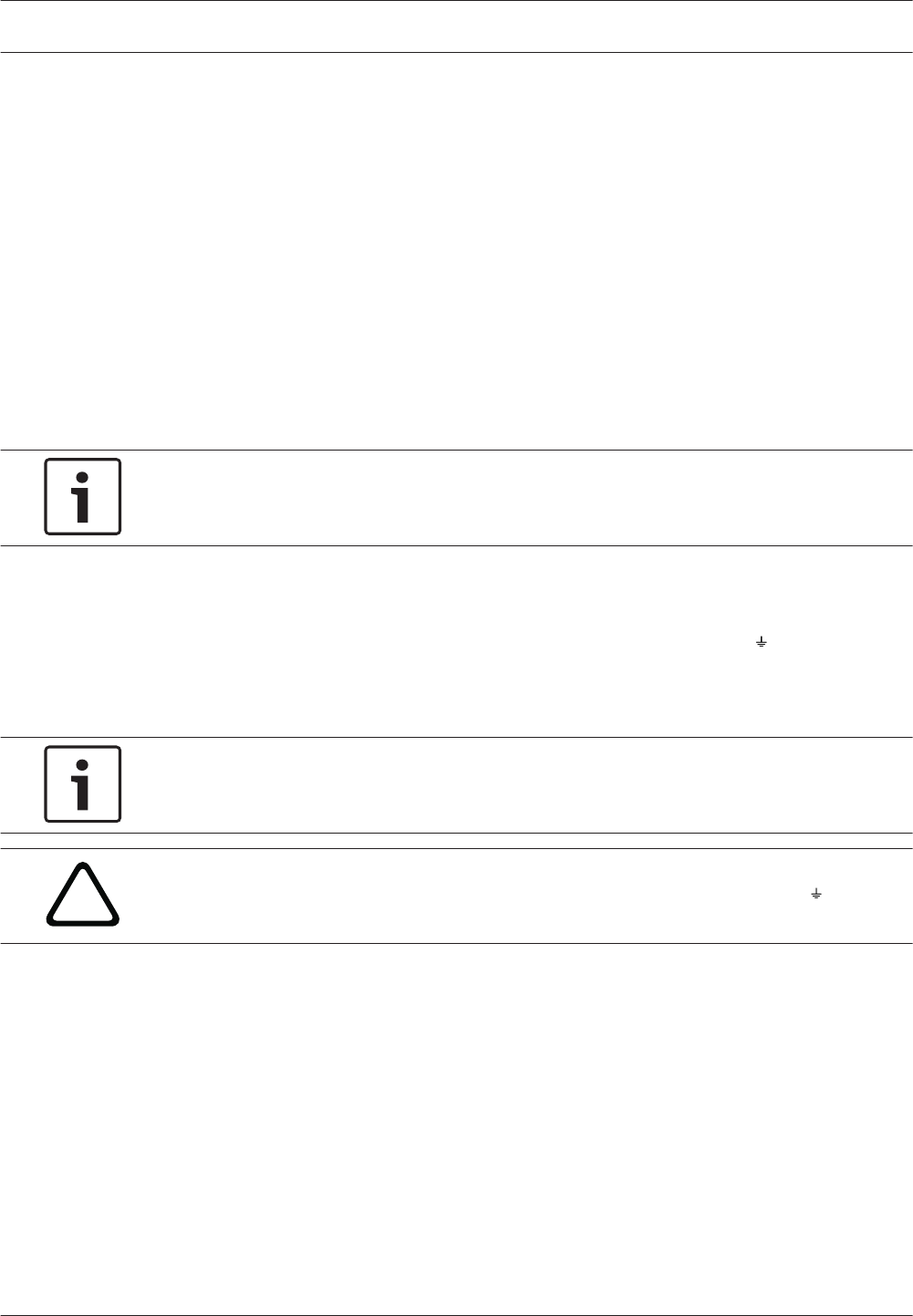
SDI2 devices daisy chained with terminal wiring
RESETZONEX TAMPER
SDI2
PWR+/R
A/Y
B/G
COM/B
PWR+/R
A/Y
B/G
COM/B
24
25
26
27
28
29
23
26
SDIx
ire
olice
ting
RESETZONEX TAMPER
SDI2
PWR+/R
A/Y
B/G
COM/B
PWR+/R
A/Y
B/G
COM/B
25
26
28
29
30
23
27
SDIx
ire
olice
ting
24
ZONEX TMPR
SDIx SDI2
MODULE RELEASE
MOD-2
MOD-1
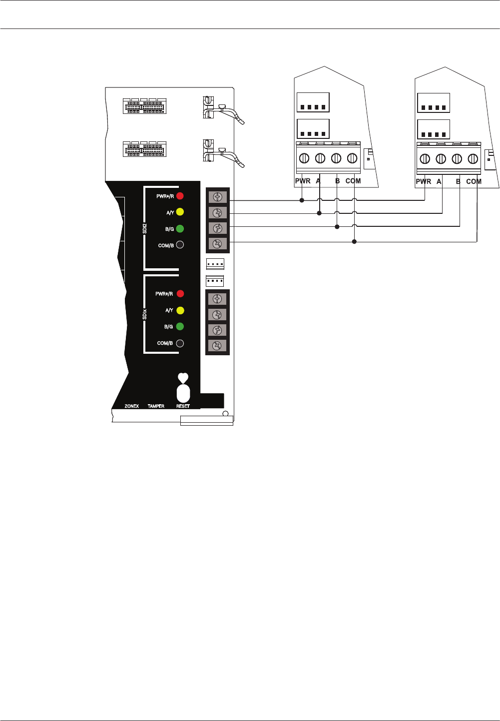
Using interconnect wiring
Interconnect wiring connectors parallel the SDI2 terminals (27 through 30 (or 23 through 26 if
configured for SDI2)). In installations with multiple SDI2 modules, using interconnect wiring
makes the installation quicker and easier than using terminal strip wiring. You use any
combination of terminal and interconnect wiring to wire multiple modules in parallel, but do
not wire a single module to the control panel using both terminal and interconnect wiring.
The interconnect wiring connectors are "keyed" (interconnect wiring plug can fit in only one
direction).
10 en | Control panel installation Control Panels
2016.05 | 05 | F.01U.304.001 UL Installation Guide Bosch Security Systems, Inc.
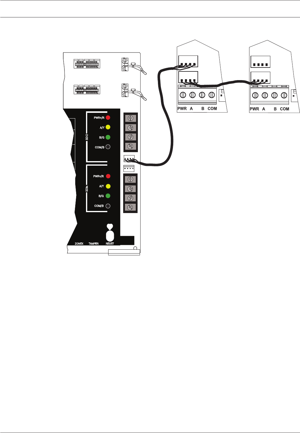
SDI2 devices daisy chained with interconnect wiring
RESETZONEX TAMPER
SDI2
PWR+/R
A/Y
B/G
COM/B
PWR+/R
A/Y
B/G
COM/B
24
25
26
27
28
29
23
26
SDIx
ire
olice
ting
RESETZONEX TAMPER
SDI2
PWR+/R
A/Y
B/G
COM/B
PWR+/R
A/Y
B/G
COM/B
25
26
28
29
30
23
27
SDIx
ire
olice
ting
24
ZONEX TMPR
SDIx SDI2
MODULE RELEASE
MOD-2
MOD-1
Control Panels Control panel installation | en 11
Bosch Security Systems, Inc. UL Installation Guide 2016.05 | 05 | F.01U.304.001
Power supply
This section provides information on installing and maintaining primary power, batteries, and
auxiliary power.
Primary (AC) power
2
1
The control panel uses a 16.5 VAC, 40 VA, internally-fused transformer (D1640) for its primary
power source. The control panel draws 190 mA when idle and 265 mA when in the alarm
state.
The auxiliary power available for powered devices is 1.4 A.
Surge protection
Transient suppressors and spark gaps protect the circuit from power surges. This protection
relies on the ground connection at the earth ground terminal (Terminal 10), marked with the
icon. Ensure that you connect the terminal to a proper ground.
Refer to Connect earth ground, page 8.
AC power fail
The system indicates an AC power failure when the transformer input terminals do not have
sufficient voltage. The AC Fail Time parameter sets the amount of time without AC power
before the control panel reports the failure, and the amount of time after the power returns
before the control panel reports restored power.
When the control panel loses AC power long enough for the battery to become low, the
control panel adds a Battery Low event to the event log. If the battery continues to discharge
below the load shed threshold, the system ceases to operate and generates no further events.
Install the transformer
!
Caution!
Do not short-circuit the terminals of the transformer: Shorting the terminals opens the
internal fuse, causing permanent failure. Connect the transformer to the control panel's AC
power terminals before plugging it into the power source.
Notice!
Plan ahead
Route telephone, SDI2 bus wiring, and sensor loop wiring away from any AC conductors,
including the transformer wire. AC wiring can induce noise and low level voltage into adjacent
wiring.
1. Use 18 AWG (1.02 mm) wire minimum (12 AWG [2 mm] maximum) and connect the
transformer to the control panel. Make the wire length as short as possible. Do not
exceed 50 ft (15 m).
2. Connect the wire to the control panel.
3. Connect the wire to the transformer.
4. Plug the transformer into an unswitched, 120 VAC, 60 Hz power outlet only.
5. Secure the transformer to the outlet with the screw provided (not applicable in
Cananda).
4
4.1
4.1.1
12 en | Power supply Control Panels
2016.05 | 05 | F.01U.304.001 UL Installation Guide Bosch Security Systems, Inc.
D8004 Transformer Enclosure required for fire systems
Use the D8004 Transformer Enclosure for the D1640 Transformer in fire and combined fire
and burglary applications.
Notice!
Check with the Authority Having Jurisdiction (AHJ) about mounting transformers on specific
circuits.
Secondary (DC) power
4 5
A 12 V sealed lead-acid rechargeable battery (such as the D126/D1218) supplies secondary
power to maintain system operation during interruptions of primary (AC) power.
Notice!
Use sealed lead acid batteries only
The charging circuit is calibrated for lead-acid batteries. Do not use gel-cell or NiCad
batteries.
Extra batteries
To increase battery back-up time, connect a second 12 V battery in parallel to the first battery.
Use a D122/D122L Dual Battery Harness to ensure proper and safe connection.
Refer to Standby battery requirements and calculations.
D1218 Battery
The D1218 is a 12 V, 18 Ah battery for use in applications requiring extended battery standby
time. The control panel does not support more than 38 Ah of battery.
Install the battery
1. Place the battery upright in the base of the enclosure.
2. Locate the red and black leads supplied in the hardware pack.
3. Connect the black battery lead to Terminal 4 and then to the negative (-) side of the
battery.
4. Connect the red battery lead to Terminal 5, and then to the positive (+) side of the
battery.
!
Warning!
High current arcs are possible. The positive (red) battery lead and Terminal 5 can create high
current arcs if shorted to other terminals or the enclosure. Use caution when working with
the positive lead and Terminal 5. Always disconnect the positive (red) lead from the battery
before removing it from Terminal 5.
!
Caution!
The battery terminals and wire are not power limited. Maintain a 0.250 in (6.4 mm) space
between the battery terminals, battery wiring, and all other wiring. Battery wiring cannot
share the same conduit, conduit fittings, or conduit knockouts with other wiring.
4.2
4.2.1
Control Panels Power supply | en 13
Bosch Security Systems, Inc. UL Installation Guide 2016.05 | 05 | F.01U.304.001
Non-power-limited wiring
USB POWER
STATUS L
I
N
K
ETHERNETUSB
B
A
S
E
T
11 13 14 16 17 19 20 22
12 15 18 21
Quick Flash:
Low
BATTERY STATUS
Slow Flash:
Charging
Off: Normal
On:
Missing
Low 12.1 VDC
Load Shed 10.2 VDC
EARTH GROUND
COMMON
BATTERY (
-
)
+ AUX POWER
BATTERY ( + )
CLASS 2
16.5 VAC 40 VA 60 Hz
TRANSFORMER
10
9
8
7
6
5
4
3
2
1
OUTPUT
B (2)
OUTPUT
A (1)
OUTPUT
C (3)
Do not connect
to a receptacle
controlled by
a switch.
Point 5 Point 6
Point 3 Point 4
Point 1 Point 2 Point 7 Point 8
ON-BOARD POINTS
1 k End-of-line-Resistors Required (P/N 15093130-004),
WARNING!
Multi-Battery
installation requires
Model D122 or D122L
Dual Battery Harness.
Improper installation
can be a fire hazard
.
WARNING!
Incorrect wiring will
damage this
equipment.
Devices powered by
any output must be
supervised.
POWER SUPPL
The Power S
refer to the B
The system is intended
panel has been approv
RevPol.
Battery: Replace every 3 to
5 years with one or two
Model D126 or D1218 12V
Lead Acid Batteries.
WARNING!
To prevent risk of shock,
disconnect AC power and
communication lines before
servicing.
All exte
Require
Voltage Ranges: Open 3.7 - 5.0 VDC,
Owner I
be removed by
POINT 1 COM POINT 2 POINT 3 COM POINT 4 POINT 5 COM POINT 6 POINT 7 COM POINT 8
12
3
4
5
6
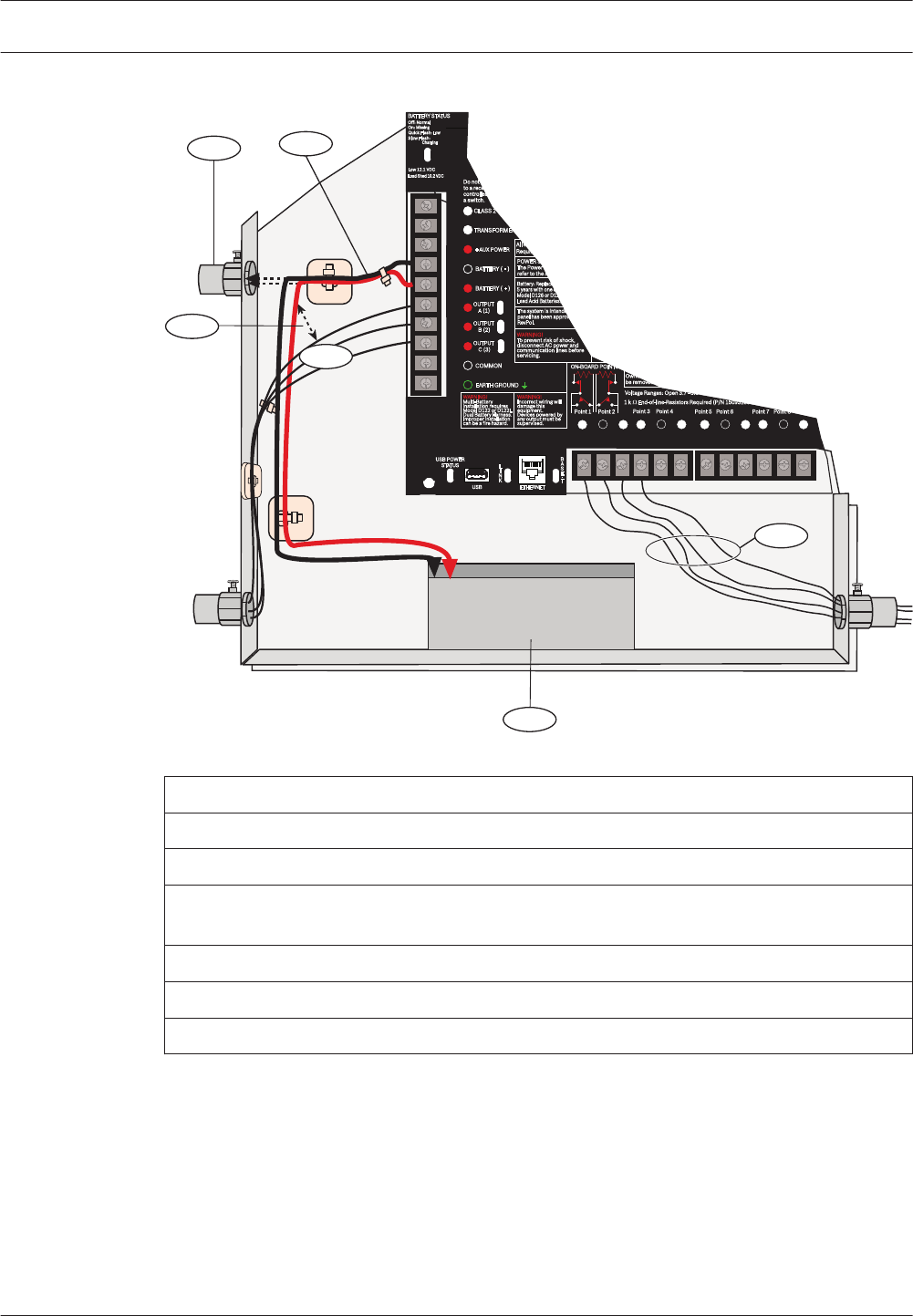
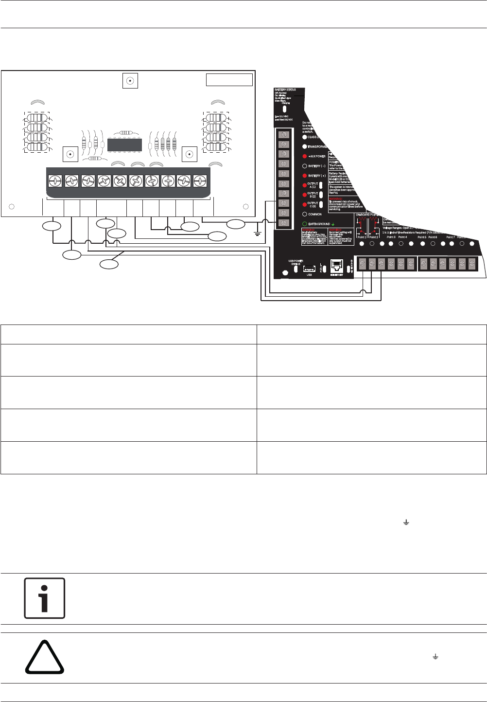
Figure 4.1: Non-power-limited wiring
Callout ᅳ Description
1 ᅳ Conduit required for use with external batteries
2 ᅳ Battery wires
3 ᅳ 0.25 in (6.4 mm) minimum. To ensure proper spacing, use tie-wraps or similar devices to
secure wires.
4 ᅳ Output wires
5 ᅳ Sensor loop wires
6 ᅳ 12 V sealed lead-acid rechargeable battery (D126/D1218)
Charge the battery
Connect the battery and then the transformer to allow the control panel to charge the battery
while you complete the installation.
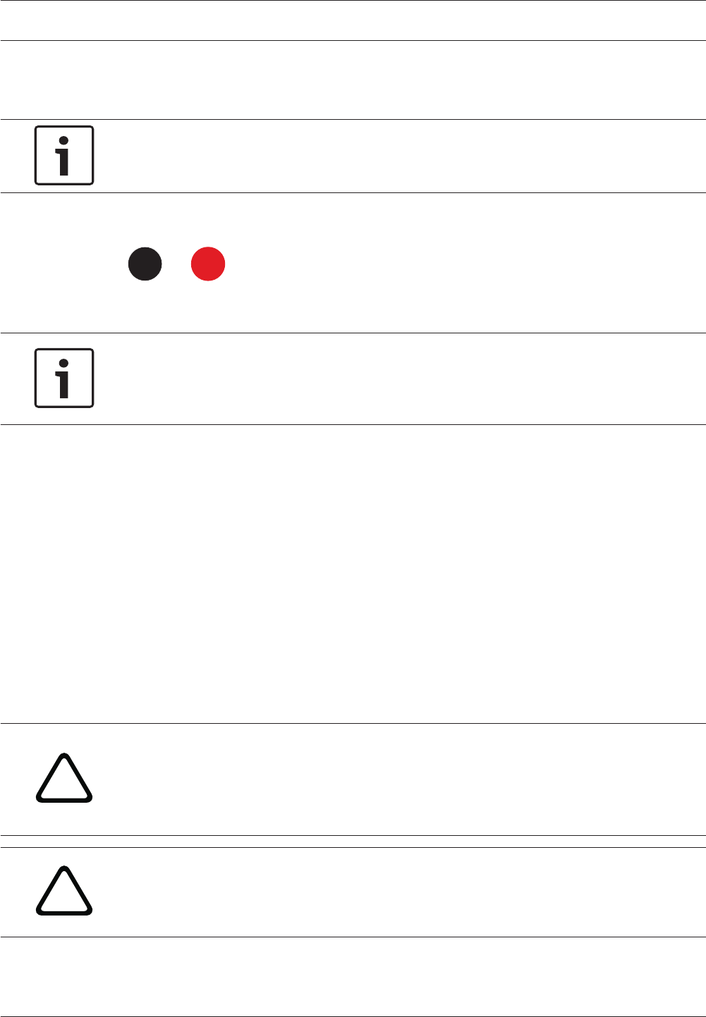
BATTERY STATUS LED
The control panel includes one BATTERY STATUS LED with 4 LED patterns to indicate the
battery status.
4.2.2
14 en | Power supply Control Panels
2016.05 | 05 | F.01U.304.001 UL Installation Guide Bosch Security Systems, Inc.
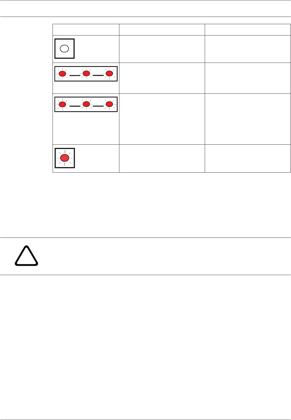
LED pattern Function Refer to
Off
Battery is fully charged.
N/A
Flashing slowly
Battery charge is below 13.4
VDC and the battery is
recharging.
Low battery, page 15 and
Battery restoral, page 15
Flashing quickly
Battery voltage dropped to
between 12.1 VDC and 10.2
VDC.
LED turns off when voltage
reaches at least 13.4 and > 200
mA.
Low battery, page 15 and
Battery restoral, page 15
On Steady
Battery is missing, shorted, or
reversed.
Missing battery, page 15
Battery maintenance
Use 12 VDC sealed lead-acid rechargeable battery (7 Ah, 18 Ah, or 38 Ah). The control panel
supports up to 38 Ah of battery. If you use two batteries, they must have the same capacity
and you must connect them using the D122/D122L Dual Battery Harness.
Replace the batteries every 3 to 5 years. If you install two batteries, replace them both at the
same time.
Record the date of installation directly on the battery.
!
Caution!
Exceeding the maximum output ratings or installing the transformer in an outlet that is
routinely switched off causes heavy discharges. Routine heavy discharges can lead to
premature battery failure.
Battery supervision
Low battery
If the control panel is programmed for power supervision, it sends a Battery Low report in the
Modem4 communication format or a Low System Battery (302) report in the Contact ID
format.
Missing battery
If the control panel is programmed for power supervision, it sends a Battery Missing/Dead
report in the Modem4 communication format, or a Control Panel Battery Missing (311) report
in the Contact ID format.
Battery restoral
When AC returns and the battery is charged, If the control panel is programmed for power
supervision, it sends a Low System Battery Restore report in the Modem4 communication
format or a Control Panel Battery Restored to Normal (302) report in the Contact ID format.
Battery charging circuit float charge
The float voltage for the battery charging circuit is 13.65 VDC when operating within load
range.
4.2.3
4.2.4
4.2.5
Control Panels Power supply | en 15
Bosch Security Systems, Inc. UL Installation Guide 2016.05 | 05 | F.01U.304.001
Load shed
Load shed relay protects battery: During an AC power loss, the battery supplies all power to
the security system. If the battery voltage falls below 10.0 V during an AC power loss, a load
shed relay disconnects the battery from the control panel and disables the control panel. Load
shed protects the battery from being damaged by deep discharge.
When AC power restores, the load shed relay reconnects the charging circuit on the control
panel to the battery and the battery begins to recharge.
Over load with AC present
If devices draw more than 1.6 A of auxiliary current from the control panel with AC applied,
the control panel indicates a Panel Over-current system trouble. Unless corrected, this
condition prevents the control panel from properly maintaining the battery charge level, and
leaves the system vulnerable to failing during power outages.
To correct the issue, remove all loads to the control panel and disconnect the battery and AC
power. Fix the condition creating the over current and reconnect AC power.
A shorted battery condition (created either by a shorted cell inside the battery or by a short
on Terminals 4 and 5), might prevent the control panel from operating, or might cause the
control panel to detect a missing battery condition.
!
Caution!
Shorting the battery terminals is dangerous.
Battery discharge and recharge schedule
Battery
discharge/
recharge
schedule
Discharge
Cycle
13.30 VDC
12.1 VDC
10.2 VDC
10.2 VDC
BATTERY STATUS LED slow flash.
Low Battery Report, if programmed.
BATTERY STATUS LED quick flash.
Minimum operational voltage.
Battery load shed.
Recharge
Cycle
AC ON
12.50 VDC (under
load)
13.4 VDC and charging
current < 200 mA
Load shed relay resets, battery charging begins.
Battery Restoral Report sent, BATTERY STATUS LED
off.
Battery float charged. BATTERY STATUS LED off.
B520 Auxiliary Power Supply
The optional B520 Auxiliary Power Supply Module provides up to 2 A of 12 VDC standby
power for Fire and Burglar applications. For Burglar applications, an additional 2 A of alarm
power is available, allowing 2 A of standby current and up to 4 A of alarm current.
The B9512G control panels support up to 8 B520 modules. The B8512G control panels
support up to 4 B520 modules.
Connect B520 Auxiliary Power Supply Modules to the SDI2 bus on the control panel using
terminals 27 through 30 (or 23 through 26 if configured for SDI2). This section includes basic
installation instructions. For detailed installation instructions, refer to the Auxiliary Power
Supply Module (B520) Installation Guide for complete installation instructions, and for battery
standby time calculations, refer to the B520 Auxiliary Power Supply Module Battery Standby
Chart within the installation guide.
4.2.6
4.3
16 en | Power supply Control Panels
2016.05 | 05 | F.01U.304.001 UL Installation Guide Bosch Security Systems, Inc.
SDI2 address settings
Notice!
The module reads the address switch setting only during module power up. If you change the
setting after you apply power to the module, you must cycle the power to the module in order
for the new setting to take effect.
If multiple B520 modules reside on the same system, each B520 module must have a unique
address.
Supervision
The control panel supervises B520 Auxiliary Power Supply Modules on the SDI2 bus.
With any failure to receive an expected response from a B520, all keypads show a system
fault. The control panel sends a module trouble report to the central station (if configured for
module trouble reports).
Auxiliary power supply trouble conditions
Each auxiliary power supply module on the SDI2 bus monitors several conditions including AC
status, battery status, over current status, and a tamper input. Each of these conditions
produces a unique system trouble condition at all keypads. The control panel sends a module
trouble report to the central station (if configured for module trouble reports).
Installation and control panel wiring (B520)
The power supply draws approximately 15 mA (+/- 1 mA) from the control panel.
Ensure that there is enough power for the module and other powered devices you want
connected to the system.
Refer to On-board outputs, page 20.
!
Caution!
Remove all power (AC and battery) before making any connections. Failure to do so might
result in personal injury and/or equipment damage.
Install the module
1. Set the module address using the address switches before you install it in the enclosure.
2. Insert the plastic mounting clips onto the appropriate standoff locations inside the
enclosure or on a mounting skirt, when required.
3. Mount the module onto the plastic mounting clips and then secure it using the supplied
mounting screws.
Wire to earth ground
To help prevent damage from electrostatic charges or other transient electrical surges,
connect the system to earth ground before making other connections. Recommended earth
ground references are a grounding rod or a cold water pipe. When grounding, run wire as
close as possible to grounding device.
!
Caution!
Do not use telephone or electrical ground for the earth ground connection. Use 14 AWG (1.8
mm) to 16 AWG (1.5 mm) wire when making the connection.
4.3.1
4.3.2
4.3.3
4.3.4
Control Panels Power supply | en 17
Bosch Security Systems, Inc. UL Installation Guide 2016.05 | 05 | F.01U.304.001
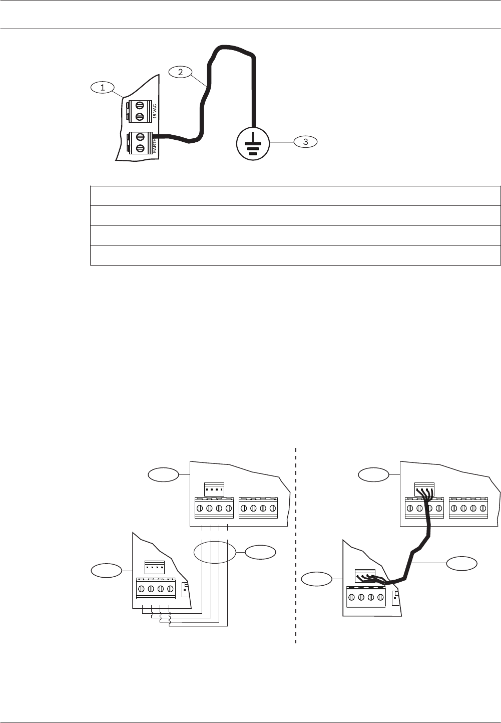
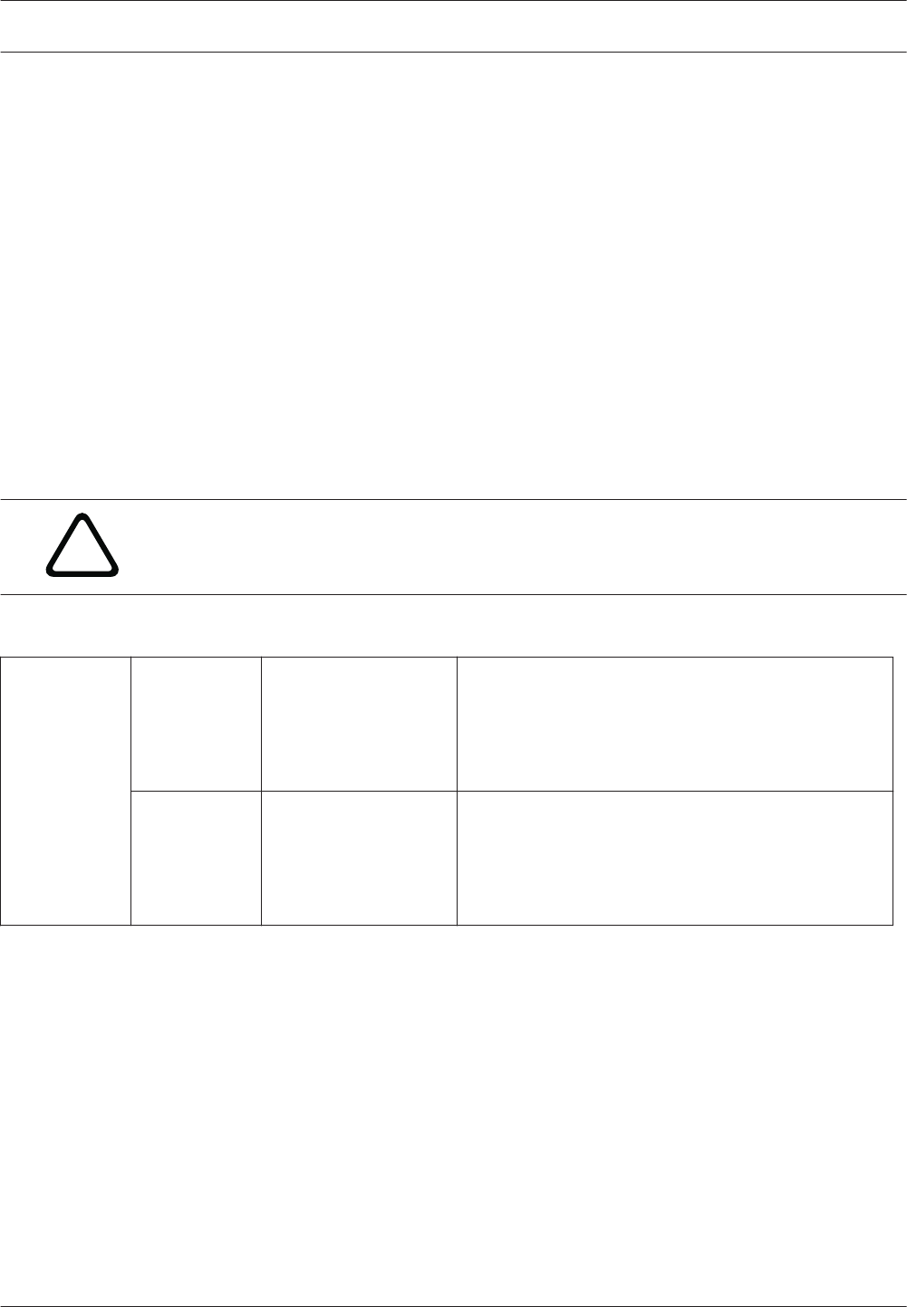
Figure 4.2: B520 earth ground wiring
Callout ᅳ Description
1 ᅳ B520 Auxiliary Power Supply Module
2 ᅳ 14 AWG - 16 AWG (1.8 mm - 1.5 mm) wire
3 ᅳ Ground device (grounding rod or cold water pipe)
Wire to the control panel
When wiring a module to a control panel, use the terminal strip labeled with PWR, A, B, and
COM for SDI2 IN to wire to corresponding control panel terminals 27 through 30 (or 23
through 26 if configured for SDI2).
Use 12 AWG to 22 AWG (2 mm to 0.65 mm) wire.
Powered device and battery wiring
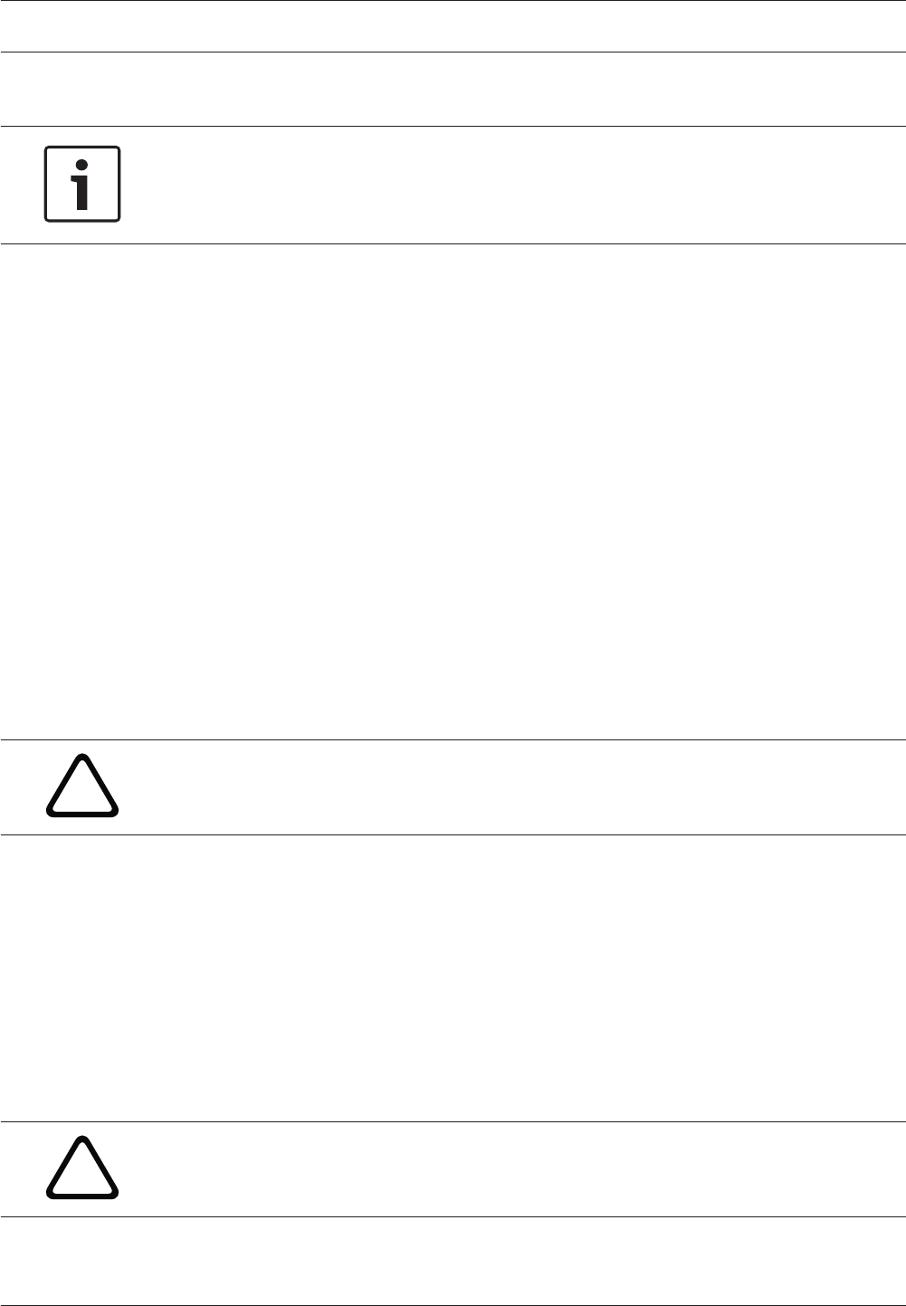
Wire to SDI2 powered devices
When wiring the output of a B520 to a SDI2 module, you can use either the SDI2 OUT terminal
strip labeled with PWR, A, B, and COM to wire to terminals labeled PWR, A, B, and COM on
the next module, or you can use the interconnect cable (included). Wiring the output of a
B520 to a SDI2 device provides power to the device while passing through data between the
control panel and the device.
PWR A B COM
2
4
PWR A B COM
SDI2 OUT SDI2 IN
PWR A B COM PWR A B COM
1
2
3
SDI2 OUT SDI2 IN
PWR A B COM PWR A B COM
1
R Y G B
Figure 4.3: B520 to powered devices - terminal strip or interconnect wiring connector
4.3.5
18 en | Power supply Control Panels
2016.05 | 05 | F.01U.304.001 UL Installation Guide Bosch Security Systems, Inc.
Callout ᅳ Description
1 ᅳ B520 Auxiliary Power Supply Module
2 ᅳ Powered device (SDI2 module)
3 ᅳ Terminal strip wiring
4 ᅳ Interconnect wiring (P/N: F01U079745)
Wire to batteries
Wiring the B520 to BATT 1 is required for proper operation of standby power for the B520
module. Wiring the second battery (BATT 2) is optional. If a B520 is configured for two
batteries as the standby power source, then BATT 2 is also required for proper operation.
BATT 2 must have the same capacity and rating as BATT 1. Maximum standby power cannot
exceed 36 Ah.
BATT 1 BATT 2
RBR B
+ -
1
23
+ -
Figure 4.4: B520 BATT terminals wiring
Callout ᅳ Description
1 ᅳ B520 Auxiliary Power Supply Module
2 ᅳ Battery 2 (BATT 2) - (12 V nominal lead acid)
3 ᅳ Battery 1 (BATT 1) - (12 V nominal lead acid)
Control Panels Power supply | en 19
Bosch Security Systems, Inc. UL Installation Guide 2016.05 | 05 | F.01U.304.001
On-board outputs
The control panel provides three powered relay outputs.
Circuit protection
The powered outputs come with circuit protection.
Four self-resetting circuit breakers protect the control panel from short circuits on the
continuous and programmable power outputs.
The self-resetting circuit breakers include:
– One self-resetting circuit breaker protects Terminal 3, auxiliary power.
– Another self-resetting circuit breaker protects:
– Terminal 6. Alarm power output
– Terminal 7. Alternate alarm power output
– Terminal 8. Switched auxiliary power
Notice!
A short circuit on one terminal disrupts power to the other two terminals.
– The third self-resetting circuit breaker protects Terminals 26 and 30, power +.
– The fourth self-resetting circuit breaker protects the ZONEX connection.
Notice!
UL requires any device powered from a power output to be supervised.
Total available power
The system produces up to 1.4 A of combined power at 12.0 VDC nominal. The outputs in this
section share the available power. These outputs appear as shown on the faceplate.
3
Auxiliary power
Power devices requiring continuous power.
6
Output A (1), Alarm power output
Programmable output normally open, power on alarm.
7
Output B (2), Alternate alarm power output
Programmable output normally open, power on alarm.
8
Output C (3), Switched auxiliary power
Programmable output normally closed, switches power off when the Sensor Reset command
is executed.
26
SDIx Power+ / R
Powers serial device interface (SDI) keypads, or use to power serial device interface 2 (SDI2)
devices, such as keypads and expansion modules.
5
5.1
5.2
20 en | On-board outputs Control Panels
2016.05 | 05 | F.01U.304.001 UL Installation Guide Bosch Security Systems, Inc.
30
SDI2 Power+ / R
Powers serial device interface 2 (SDI2) devices, such as keypads and expansion modules.
ZONEX Power
Powers ZONEX modules such as the D8125, D8128D, and D8129 connected through the B600.
Continuous power outputs
3
26
30
The continuous current draw for powered devices connected to Terminals 3, 26, and 30, and
the ZONEX connector must not exceed 1.4 A. Devices powered from these outputs operate at
12.0 VDC Nominal.
Notice!
Power Restricted for Fire and Combined Fire and Burglary Systems
Use the Fire system power formula, page 22 to calculate the current available for fire and
combined fire and burglary systems
Programmable power outputs
6
7
8
The power outputs at Terminals 6, 7, and 8 are programmed as Outputs A (1), B (2), and C
(3).
Assign each output an output type (Fire Bell, for example), when assigning it to an area. You
can assign an output to one or more areas.
The defaults are:
– Output A (1) - Terminal 6 - as a Steady Alarm Bell output
– Output B (2) - Terminal 7 - as a Pulsed Fire Bell output
– Output C (3) - Terminal 8 - as a Verification or Reset output for smoke detectors
The Program Entry Guide contains complete instructions for programming outputs. Refer to
the Bell Parameters section of the program to set the Fire Bell, Alarm Bell output responses
for outputs. Four annunciation patterns are available: Steady, Pulsed, California Standard,
and Temporal Code 3.
If Terminals 6, 7, and 8 do not provide the expected output, check:
– The Outputs section of the program for Outputs A (1), B (2), and C (3).
– The Bell Parameters section of the program to confirm that the Alarm and Fire Bell
responses are programmed for the expected duration and pattern.
– The Point Assignments section to confirm that each point is programmed for the expected
local response.
Terminals 6 and 7
6
7
When activated, Terminals 6 (Output A) and 7 (Output B), provide a positive (+) 12.0 VDC
Nominal power output. Use the power at Terminals 6 and 7 to power bells, siren drivers,
piezoelectric fire sounders, electronic horns, or other devices.
Programming determines the format of the output and the conditions that activate it.
5.3
5.4
5.4.1
Control Panels On-board outputs | en 21
Bosch Security Systems, Inc. UL Installation Guide 2016.05 | 05 | F.01U.304.001

When using Output A or Output B to activate notification appliance circuits in UL Listed fire
alarm applications, install a D192G Notification Appliance Circuit (NAC) Module.
Power restricted for Fire and Combined Fire and Burglary Systems
Fire systems are prohibited from using the battery for supplying alarm power. Use the fire
system power formula that follows to calculate the current available for fire and combined fire
and burglary systems.
Fire system power formula
Calculating the current available at Terminals 6 and 7 for fire and combined fire and burglary
systems:
1. Add together the current draws for all devices connected to Terminals 3, 26, and 30, and
the ZONEX connector. This is the total current required for the normal standby condition
(NSC).
2. The current available for NSC is 1.4 A. Subtract the NSC current required calculated in
Step 1 from the NSC current available, 1.4 A. The difference is the alarm current available
for Terminals 6 and 7.
In formula format: 1.4 A – NSC current required (Step 1) = Alarm current available
Refer to Approved applications for module or accessory current requirements
Terminal 8
8
Terminal 8 provides continuous positive (+) 12.0 VDC Nominal power. Output C interrupts the
power at Terminal 8 when activated. Use Terminal 8 to power smoke detectors or other
devices that reset by interrupting power.
Verify and reset Output C
The default program sets Output C (Terminal 8) as a verification and reset output. Refer to
Output Parameters and Point Assignments in the control panel Program Entry Guide for
instructions on programming verification and resetting outputs and points.
Performing a sensor reset at a keypad produces a five-second activation of verification and
reset outputs. The control panel ignores verification and resettable points during the five
seconds.
USB power
3
USB
In addition to connecting RPS to the control panel for programming, you can use the USB port
on the control panel to power USB-powered devices.
When enabled, the USB port provides 500 mA of 5 V power, which it draws from the control
panel. Ensure that there is enough power for all the powered devices you want to connect to
the system.
Enable USB power by pressing the control panel RESET button 3 times, or using the keypad
Installer menu (refer to [7] USB Power). The USB POWER STATUS LED lights when power to
the USB is turned on. Press the control panel RESET button 3 times to turn power off, if
desired.
5.4.2
5.5
22 en | On-board outputs Control Panels
2016.05 | 05 | F.01U.304.001 UL Installation Guide Bosch Security Systems, Inc.
Control panel board overview
POINT 1 COM POINT 2 POINT 3 COM POINT 4 POINT 5 COM POINT 6 POINT 7 COM POINT 8
ZONEX TMPR
SDIx SDI2
MODULE RELEASE
MOD-2
MOD-1
USB POWER
STATUS
RESETZONEX TMPR
SDI2
PWR+/R
A/Y
B/G
COM/B
PWR+/R
A/Y
B/G
COM/B
B
A
S
E
L
I
N
KT
ETHERNET
USB
11
Point 5 Point 6
Point 3 Point 4
Point 1 Point 2 Point 7 Point 8
EARTH GROUND
ON-BOARD POINTS
COMMON
BATTERY (
-
)
+ AUX POWER
BATTERY ( + )
CLASS 2
16.5 VAC 40 VA 60 Hz
TRANSFORMER
10
9
8
7
6
5
4
3
2
1
1 k End-of-line-Resistors Required (P/N 15093130-004), Max Loop Current: 5 mA
13 14 16 17 19 20 22
12 15 18 21
24
25
26
28
29
30
23
27
Quick Flash:
Low
BATTERY STATUS
Slow Flash:
Charging
Off: Normal
Minimum system requirements for Classification in accordance with ANSI/SIA
CP-01-2010. UL Listed and Classified control unit Model B9512G and B8512G.
UL Listed and Classified keypad Model B942, B930, B925F, B926F, B921C,
B920, B915, D1255RB, D1256RB and D1257RB. UL Listed Local Bell.
WARNING!
Multi-Battery
installation requires
Model D122 or D122L
Dual Battery Harness.
Improper installation
can be a fire hazard
.
WARNING!
Incorrect wiring will
damage this
equipment.
Devices powered by
any output must be
supervised.
The equipment should be installed in accordance with the NFPA 70 (National Electrical
Code) and NFPA 72 (National Fire Alarm Code).
Depending on the application, the installation may need to be in accordance with one or
more of the following UL standards: UL681, UL1076, UL1641 and C22.1, CEC, Part 1.
Use of a D185 is not suitable for remote station protected premises service where separate
transmissions circuits are required for fire, supervisory (when applicable) and trouble
signals.
SDIx
Refer to the system wiring diagrams in the B9512G/B8512G
ULLD and to the D125B Installation Instructions for compatible
smoke detectors. 2-wire Compatible Identifier “A”. Printed
information describing proper installation, operation, testing,
maintenance, repair service and response to an alarm is to be
provided with this equipment.
POWER SUPPLY REQUIREMENTS
The Power Supply provides a maximum of 1.4 Amps for the Control Panel and all Accessory Devices. For System Loading,
refer to the B9512G/B8512G UL Listing Document, ULLD. Auxiliary powered devices: 11.8 to 12.5 VDC
The system is intended to be checked by a Qualified Technician at least every 3 years. The types of initiating circuits the control
panel has been approved for are A, M, WF, SS. The types of signaling the control panel has been approved for are DAC, OT, NC,
RevPol.
Battery: Replace every 3 to
5 years with one or two
Model D126 or D1218 12V
Lead Acid Batteries.
The B9512G/B8512G Control Panel is UL Listed For CS, RS, L, AUX, Prop and Res Fire and Res, Prop,
Cent. Stat, Local, and PS Con. Merc. Burg, MSV, BSV, Holdup, suitable as a dual line trans. sys.
Signaling means: DAC, Cell or IP
WARNING!
To prevent risk of shock,
disconnect AC power and
communication lines before
servicing.
All external connections except Terminal 5 (BATTERY(+) are inherently power limited.
Requirements for battery standby time might reduce allowable output.
On:
Missing
Low 12.1 VDC
Load Shed 10.2 VDC
OUTPUT
B (2)
OUTPUT
A (1)
OUTPUT
C (3)
Do not connect
to a receptacle
controlled by
a switch.
Voltage Ranges: Open 3.7 - 5.0 VDC, Short 0.0 - 1.3 VDC, Normal 2.0 - 3.0 VDC
WARNING!
Owner Instructions (P/N F.01U.307.371): Not to
be removed by anyone except occupant.
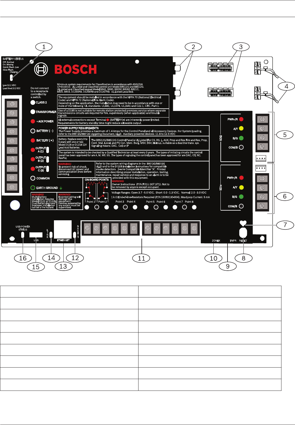
Figure 6.1: Control panel board overview
Callout ᅳ Description Callout ᅳ Description
1 ᅳ BATTERY STATUS LED 9 ᅳ Tamper switch connector location
2 ᅳ Holes to stabilize plug-in modules 10 ᅳ Zonex module connector location
3 ᅳ Plug-in module connectors 11 ᅳ Sensor loop terminals for points 1 to 8
4 ᅳ Plug-in module connector 12 ᅳ BASE-T LED (green)
5 ᅳ SDI2 wiring 13 ᅳ On-board Ethernet connector
6 ᅳ SDIx wiring (use as SDI or SDI2) 14 ᅳ LINK LED (yellow)
7 ᅳ Heartbeat LED (blue) 15 ᅳ USB connector
8 ᅳ RESET button 16 ᅳ USB POWER STATUS LED
6
Control Panels Control panel board overview | en 23
Bosch Security Systems, Inc. UL Installation Guide 2016.05 | 05 | F.01U.304.001

System wiring diagrams
Notice!
For UL Certificated accounts, add additional power using only a UL Listed 12.0 VDC
regulated, power-limited power supply such as the B520 Auxiliary Power Supply Module.
All terminals except Outputs A (1), B (2), and C (3) (Terminals 6, 7, and 8) are supervised.
For proper supervision, do not loop wire under terminals. Break the wire run to provide
supervision of connections.
7
24 en | System wiring diagrams Control Panels
2016.05 | 05 | F.01U.304.001 UL Installation Guide Bosch Security Systems, Inc.
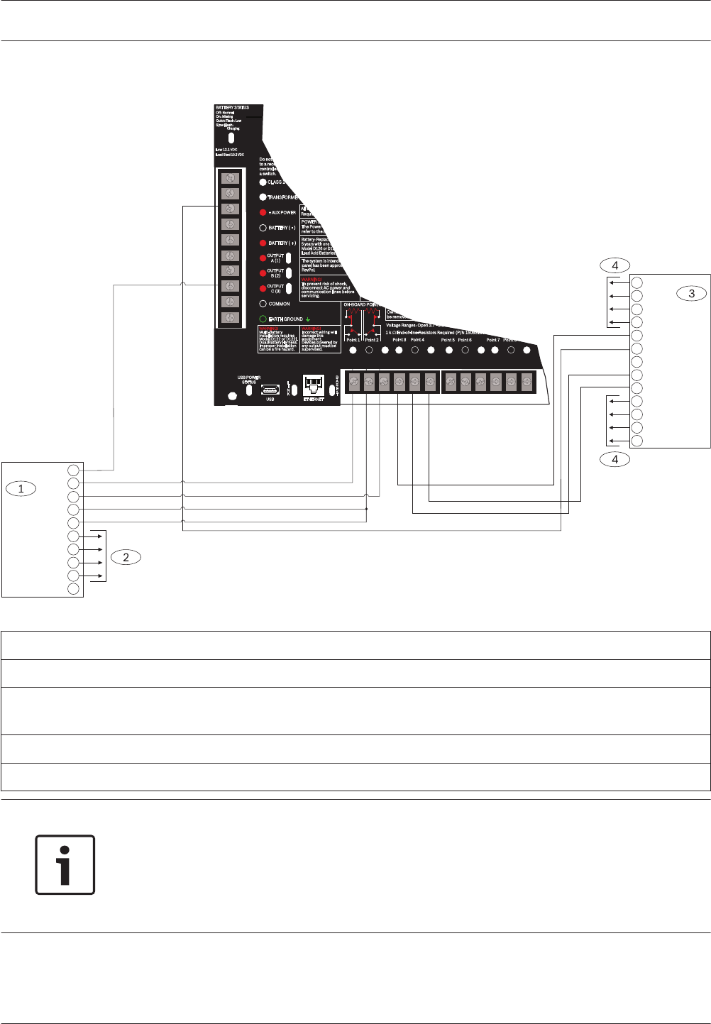
Power supply side wiring
+
AUX PWR
ALARM TRIG
COM
SUPV IN
ALARM CKT
-
BAT 2+
BAT 1+
BAT 2-
BAT 1- SUPV
CHGR+
CHGR-
VAUX+
6
7
11
10
12
13
9
5
8
USB POWER
STATUS L
I
N
K
ETHERNETUSB
B
A
S
E
T
11 13 14 16 17 19 20 22
12 15 18 21
Quick Flash:
Low
BATTERY STATUS
Slow Flash:
Charging
Off: Normal
On:
Missing
Low 12.1 VDC
Load Shed 10.2 VDC
EARTH GROUND
COMMON
BATTERY (
-
)
+ AUX POWER
BATTERY ( + )
CLASS 2
16.5 VAC 40 VA 60 Hz
TRANSFORMER
10
9
8
7
6
5
4
3
2
1
OUTPUT
B (2)
OUTPUT
A (1)
OUTPUT
C (3)
Do not connect
to a receptacle
controlled by
a switch.
Point 5 Point 6
Point 3 Point 4
Point 1 Point 2 Point 7 Point 8
ON-BOARD POINTS
1 k End-of-line-Resistors Required (P/N 15093130-004),
WARNING!
Multi-Battery
installation requires
Model D122 or D122L
Dual Battery Harness.
Improper installation
can be a fire hazard
.
WARNING!
Incorrect wiring will
damage this
equipment.
Devices powered by
any output must be
supervised.
POWER SUPPL
The Power S
refer to the B
The system is intended
panel has been approv
RevPol.
Battery: Replace every 3 to
5 years with one or two
Model D126 or D1218 12V
Lead Acid Batteries.
WARNING!
To prevent risk of shock,
disconnect AC power and
communication lines before
servicing.
All exte
Require
Voltage Ranges: Open 3.7 - 5.0 VDC,
Owner I
be removed by
POINT 1 COM POINT 2 POINT 3 COM POINT 4 POINT 5 COM POINT 6 POINT 7 COM POINT 8
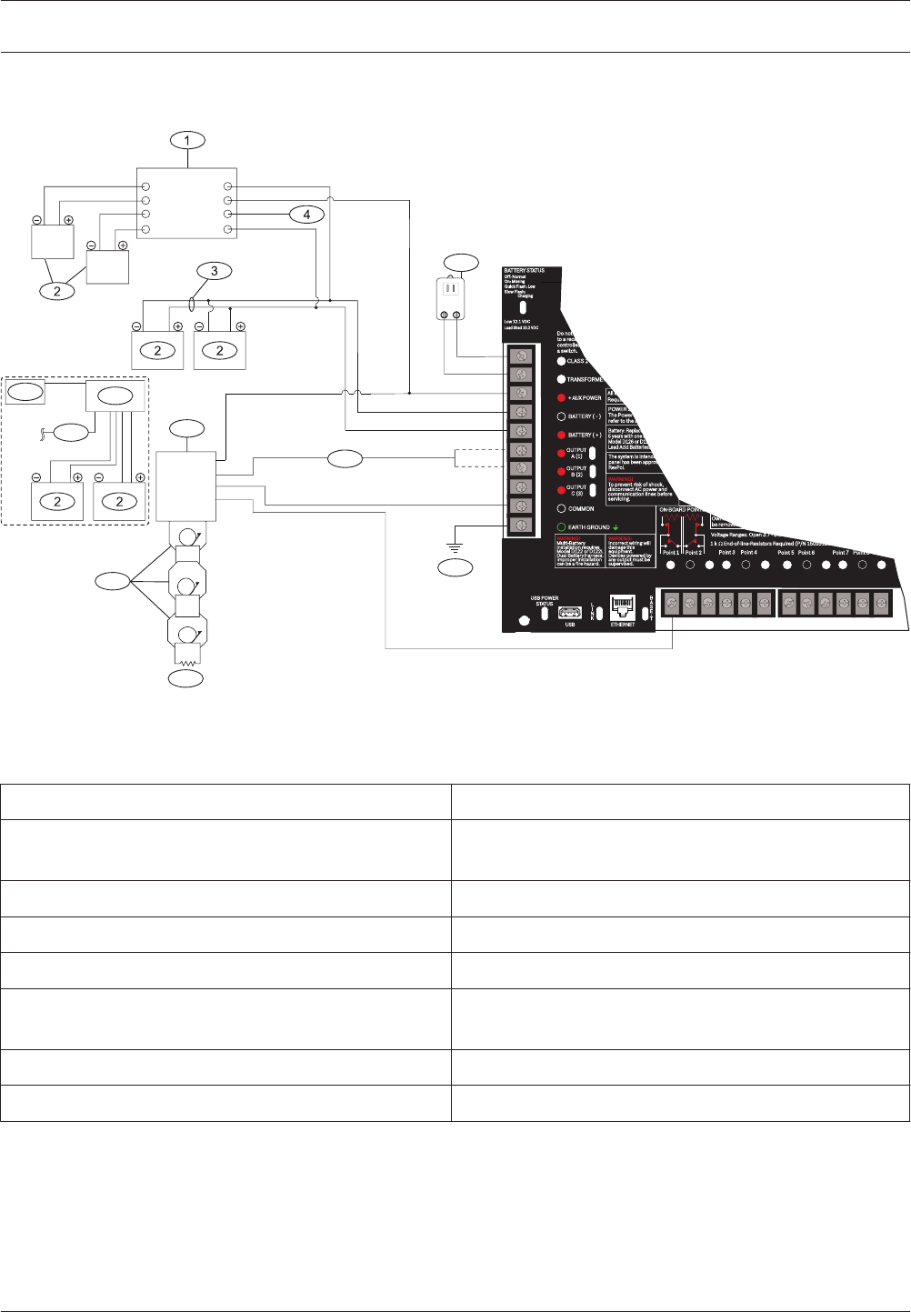
Figure 7.1: Power supply side wiring
Callout ᅳ Description Callout ᅳ Description
1 ᅳ D113 Battery Lead Supervision Module, if required
by local AHJ
8 ᅳ To control panel SDI2 wiring
2 ᅳ Batteries 9 ᅳ D192G Bell Supervision Module
3 ᅳ D122/D122L Dual Battery Harness, as required 10 ᅳ To OUTPUT A (1) or OUTPUT B (2)
4 ᅳ To supervision point 11 ᅳ 560 Ω, 2 W EOL resistor (P/N: 15-03130-005)
5 ᅳ D1640 Transformer 12 ᅳ Listed audible signaling devices rated at 12.0 VDC
nominal (do not use vibrating type horns)
6 ᅳ B520 Auxiliary Power Supply Module 13 ᅳ To earth ground
7 ᅳ To powered devices
7.1
Control Panels System wiring diagrams | en 25
Bosch Security Systems, Inc. UL Installation Guide 2016.05 | 05 | F.01U.304.001
Input points wiring with D125B, D130, or D129
Sw. Aux Pwr
Zone B
Zone A
Pnl Common
Pnl Common
Loop B-
Loop A-
Loop B+
Loop A+
Earth Ground 10
9
5
4
3
8
2
1
7
6
Aux Power
Zone B
Zone A
Common
Loop B-
Loop A-
Loop B+
Loop A+
Earth Ground
Loop A+
Loop A-
Loop B+
Loop B-
10
9
5
4
3
8
2
1
7
6
11
12
13
USB POWER
STATUS L
I
N
K
ETHERNETUSB
B
A
S
E
T
11 13 14 16 17 19 20 22
12 15 18 21
Quick Flash:
Low
BATTERY STATUS
Slow Flash:
Charging
Off: Normal
On:
Missing
Low 12.1 VDC
Load Shed 10.2 VDC
EARTH GROUND
COMMON
BATTERY (
-
)
+ AUX POWER
BATTERY ( + )
CLASS 2
16.5 VAC 40 VA 60 Hz
TRANSFORMER
10
9
8
7
6
5
4
3
2
1
OUTPUT
B (2)
OUTPUT
A (1)
OUTPUT
C (3)
Do not connect
to a receptacle
controlled by
a switch.
Point 5 Point 6
Point 3 Point 4
Point 1 Point 2 Point 7 Point 8
ON-BOARD POINTS
1 k End-of-line-Resistors Required (P/N 15093130-004),
WARNING!
Multi-Battery
installation requires
Model D122 or D122L
Dual Battery Harness.
Improper installation
can be a fire hazard
.
WARNING!
Incorrect wiring will
damage this
equipment.
Devices powered by
any output must be
supervised.
POWER SUPPL
The Power S
refer to the B
The system is intended
panel has been approv
RevPol.
Battery: Replace every 3 to
5 years with one or two
Model D126 or D1218 12V
Lead Acid Batteries.
WARNING!
To prevent risk of shock,
disconnect AC power and
communication lines before
servicing.
All exte
Require
Voltage Ranges: Open 3.7 - 5.0 VDC,
Owner I
be removed by
POINT 1 COM POINT 2 POINT 3 COM POINT 4 POINT 5 COM POINT 6 POINT 7 COM POINT 8
Figure 7.2: Input wiring with a D125B and a D129
Callout ᅳ Description
1 ᅳ D125B Dual Class B Initiating Module
2 ᅳ To compatible UL listed two-wire smoke detectors. Refer to the D125B Installation Instructions for a listing of
compatible two-wire smoke detectors.
3 ᅳ D129 Dual Class A Initiation Circuit Module
4 ᅳ For wiring instructions, refer to the D129 Dual Class A Initiation Circuit Module Installation Instructions.
Notice!
Use zero retard except for waterflow devices.
All external connections except Terminal 5 (battery positive) are power limited.
Optionally, for 24 V applications use a UL 1481 listed, regulated, power-limited 24 VDC power
supply with a D130 Relay Module. Refer to the D130 Installation Instructions for correct wiring
requirements.
7.2
26 en | System wiring diagrams Control Panels
2016.05 | 05 | F.01U.304.001 UL Installation Guide Bosch Security Systems, Inc.
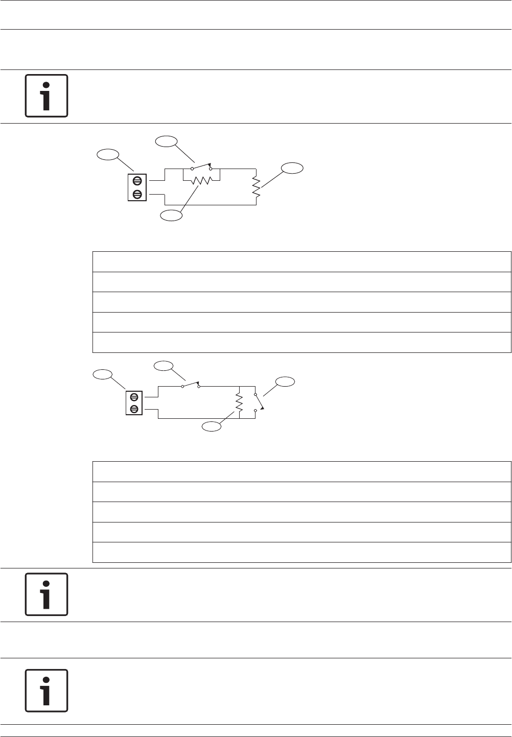
Input points wiring with or without EOL resistors
Notice!
For the dual EOL resistor circuit style order ICP-1K22AWG-10, package of 10 1.0 kΩ EOL
resistors.
Point
COM
NC
1
4
3
2
Figure 7.3: Input wiring with dual EOL resistors
Callout - Description
1 - Point sensor loop terminals
2 - Normally closed device (contact)
3 - 1.0 kΩ resistor at device
4 - 1.0 kΩ resistor at EOL (end-of-line)
Point
COM
1
3
4
2
Figure 7.4: Single EOL (NC or NO)
Callout - Description
1 - Point sensor loop terminals
2 - Normally closed device (contact)
3 - Normally open device (contact)
4 - EOL Resistor – 1.0 kΩ (2.0 kΩ and No EOL optional)
Notice!
The No EOL option does not support the use of NO and NC contacts simultaneously.
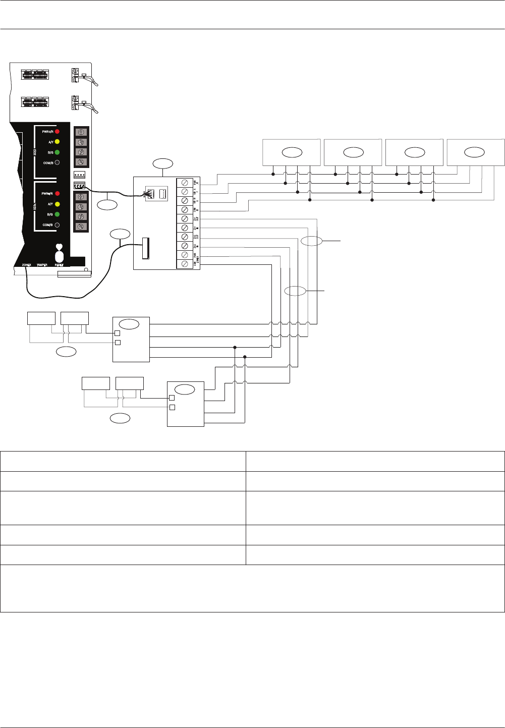
SDI and ZONEX wiring
Notice!
Install Fire and Intrusion devices only on separate circuits. Refer to the ICP-SDI-9114
Installation Instructions (P/N: F01U030068).
All external connections except Terminal 5 (battery positive) are power limited.
7.3
7.4
Control Panels System wiring diagrams | en 27
Bosch Security Systems, Inc. UL Installation Guide 2016.05 | 05 | F.01U.304.001
POPITPOPIT
In
Out
Aux
Gn
+-
4
5
7
6
POPIT POPIT
In
Out
Aux
Gnd
+-
4
5
1
2233
ZONEX 1
ZONEX 2
SDI2
RESETZONEX TAMPER
SDI2
PWR+/R
A/Y
B/G
COM/B
PWR+/R
A/Y
B/G
COM/B
24
25
26
27
28
29
23
26
SDIx
ire
olice
ting
RESETZONEX TAMPER
SDI2
PWR+/R
A/Y
B/G
COM/B
PWR+/R
A/Y
B/G
COM/B
25
26
28
29
30
23
27
SDIx
ire
olice
ting
24
ZONEX TMPR
SDIx SDI2
MODULE RELEASE
MOD-2
MOD-1
Figure 7.5: SDI and ZONEX wiring
Callout ᅳ Description Callout ᅳ Description
1 ᅳ B600 5 ᅳUp to 119 D9127U/T POPITs
2 ᅳ SDI keypads when configuring SDIx for SDI (refer
to System power/size)
6 ᅳ ZONEX connection cable (P/N: F01U295103)
(included)
3 ᅳ Up to 8 D9210C Access Control Interface Modules 7 ᅳ Interconnect cable (P/N: F01U079745) (included)
4 ᅳ D8125 POPEX Modules
*The number of D8129 Octo-relay modules allowed for each ZONEX terminal on the B600 is limited by the number
of D8128D OctoPOPITs connected to the same terminal. Refer to the D8128D Installation Guide (P/N:
F01U070537) or the D8129 Operation and Installation Guide (P/N: F01U036302) for specific information.
28 en | System wiring diagrams Control Panels
2016.05 | 05 | F.01U.304.001 UL Installation Guide Bosch Security Systems, Inc.
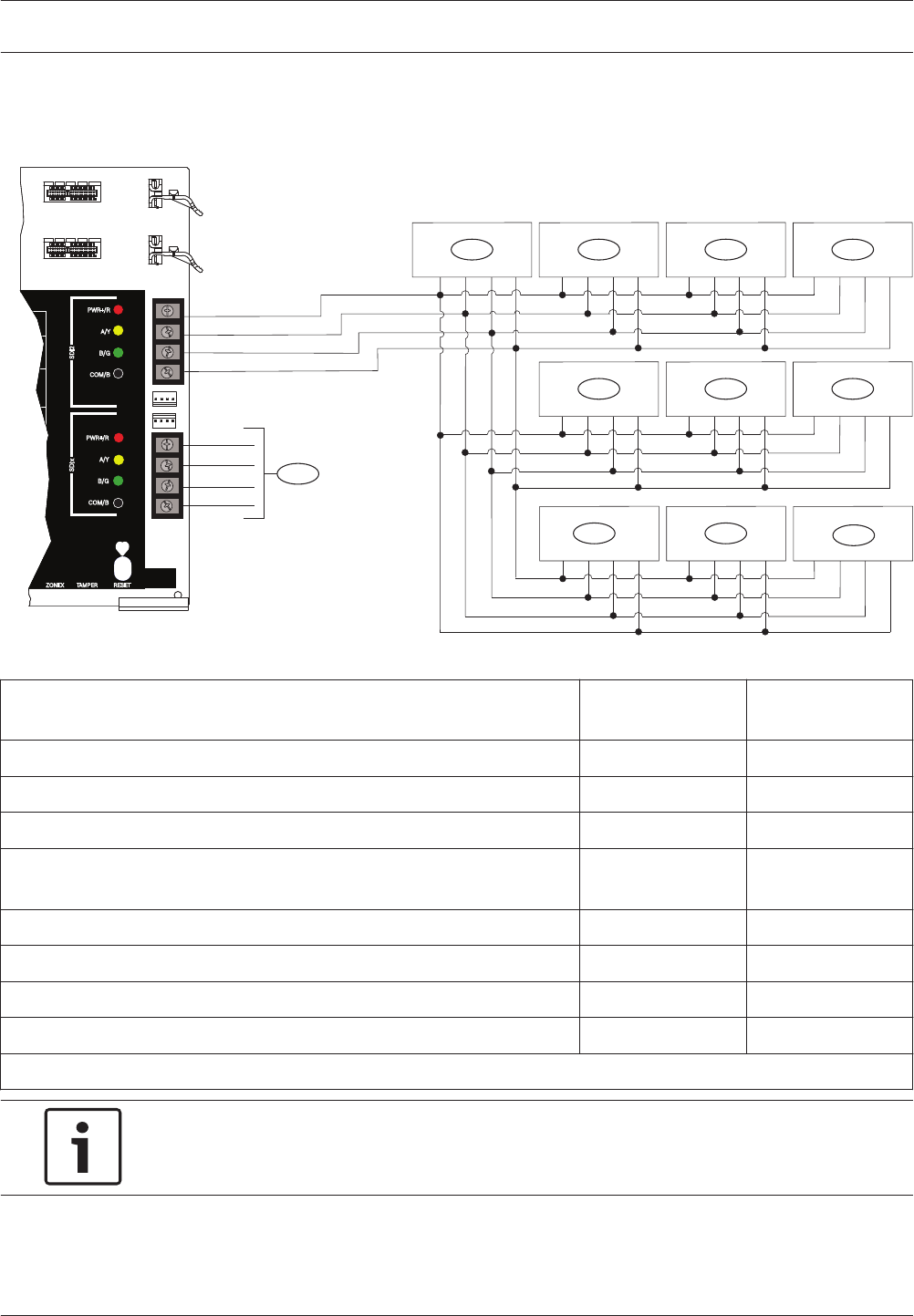
SDI2 devices general system wiring
1 432
765
9
8
88
RESETZONEX TAMPER
SDI2
PWR+/R
A/Y
B/G
COM/B
PWR+/R
A/Y
B/G
COM/B
24
25
26
27
28
29
23
26
SDIx
ire
olice
ting
RESETZONEX TAMPER
SDI2
PWR+/R
A/Y
B/G
COM/B
PWR+/R
A/Y
B/G
COM/B
25
26
28
29
30
23
27
SDIx
ire
olice
ting
24
ZONEX TMPR
SDIx SDI2
MODULE RELEASE
MOD-2
MOD-1
Figure 7.6: SDI2 devices system wiring
Callout ᅳ Description B9512G/B9512G-E
Capacity
B8512G/B8512G-E
Capacity
1 ᅳ B208 Octo-input Modules 59 9
2 ᅳ B299 POPEX Module 6 1
3 ᅳ B308 Octo-output Modules 59 9
4 ᅳ B426 Conettix Ethernet Communication Modules or B450 Conettix
Plug-in Communicator Interfaces
2 2
5 ᅳ B520 Auxiliary Power Supply Modules 8 4
6 ᅳ B810 wireless receivers or B820 SDI2 Inovonics Interface Modules 1 1
7 ᅳ B901 Access Control Modules 32 8
8 ᅳ SDI2 keypads 32 16
9 ᅳ Configurable for SDI keypads and access control interface modules, or SDI2 devices
Notice!
Each SDI2 bus supports up to 99 devices.
The SDI2 power terminal (PWR+/R) is power limited. The SDI2 terminals are supervised.
7.5
Control Panels System wiring diagrams | en 29
Bosch Security Systems, Inc. UL Installation Guide 2016.05 | 05 | F.01U.304.001
SDI2 bus wiring recommendations
Use the following SDI2 bus wiring recommendations for SDI2 installation. The control panel
and SDI2 modules use the SDI2 bus to communicate with one another.
You can wire modules via home run, daisy chain, or single level T-tap anywhere on the SDI2
bus.
2 2 2
3
2
2 2
24
2
2
2
5
1
2 2
RESETZONEX TAMPER
SDI2
PWR+/R
A/Y
B/G
COM/B
PWR+/R
A/Y
B/G
COM/B
24
25
26
27
28
29
23
26
SDIx
ire
olice
ting
RESETZONEX TAMPER
SDI2
PWR+/R
A/Y
B/G
COM/B
PWR+/R
A/Y
B/G
COM/B
25
26
28
29
30
23
27
SDIx
ire
olice
ting
24
ZONEX TMPR
SDIx SDI2
MODULE RELEASE
MOD-2
MOD-1
Figure 7.7: SDI2_Wiring_Recommendations
Callout ᅳ Description
1 ᅳ Control panel
2 ᅳ SDI2 device (module or keypad)
3 ᅳ Daisy chain wiring
4 ᅳ Single-level T-tapped wiring
5 ᅳ Home run wiring
Notice!
There can only be a difference of 2 volts (maximum) between the AUX power terminals of the
control panel or power supply and the device for the modules and keypads to work properly
under all conditions.
7.5.1
30 en | System wiring diagrams Control Panels
2016.05 | 05 | F.01U.304.001 UL Installation Guide Bosch Security Systems, Inc.
Maximum cable lengths
Follow these rules when wiring the SDI2 bus:
– The SDI2 bus requires the use of unshielded cable from 12 AWG to 22 AWG.
– Refer to the SDI2 device or keypad documentation for the allowable maximum distance
from the control panel.
– Maximum overall cable lengths are listed in the following table:
Cable capacitance Overall cable length Cable capacitance Overall cable length
pF/ft ft pF/ft ft
< 17 7500 27 5185
18 7500 28 5000
19 7350 29 4828
20 7000 30 4700
21 6666 31 4516
22 6363 32 4400
23 6086 33 4242
24 5800 34 4100
25 5600 35 4000
26 5385 36 3800
Table 7.1: Maximum cable length
Notice!
Use unshielded cable only.
Maximum capacitance of 140nF (140,000 pF) per system. Contact the wire manufacturer for
the capacitance ratings of the wire being used.
Control Panels System wiring diagrams | en 31
Bosch Security Systems, Inc. UL Installation Guide 2016.05 | 05 | F.01U.304.001
2-wire smoke wiring (D125B)
CCD 0x - 0xxxx - 000 © RADIONICS INC.
D125B
1992
1
SWITCH
POWER
10
EARTH
GND
2
ZONE
B
4 5
PANEL
COMMON
3
ZONE
A
6
B-
LOOP
7
A-
LOOP
8
B+
LOOP
9
A+
LOOP
R21
R9
R10
R14 R11
R12
R22
RV2
RV3
RV4
R8
RV1
TB1/J1
R3
C1
R7
C3
C2
R13
R4
R5
R6
U1
PTC2 PTC1
R1
R2
D125B
USB POWER
STATUS L
I
N
K
ETHERNETUSB
B
A
S
E
T
11 13 14 16 17 19 20 22
12 15 18 21
Quick Flash:
Low
BATTERY STATUS
Slow Flash:
Charging
Off: Normal
On:
Missing
Low 12.1 VDC
Load Shed 10.2 VDC
EARTH GROUND
COMMON
BATTERY (
-
)
+ AUX POWER
BATTERY ( + )
CLASS 2
16.5 VAC 40 VA 60 Hz
TRANSFORMER
10
9
8
7
6
5
4
3
2
1
OUTPUT
B (2)
OUTPUT
A (1)
OUTPUT
C (3)
Do not connect
to a receptacle
controlled by
a switch.
Point 5 Point 6
Point 3 Point 4
Point 1 Point 2 Point 7 Point 8
ON-BOARD POINTS
1 k End-of-line-Resistors Required (P/N 15093130-004),
WARNING!
Multi-Battery
installation requires
Model D122 or D122L
Dual Battery Harness.
Improper installation
can be a fire hazard
.
WARNING!
Incorrect wiring will
damage this
equipment.
Devices powered by
any output must be
supervised.
POWER SUPPL
The Power S
refer to the B
The system is intended
panel has been approv
RevPol.
Battery: Replace every 3 to
5 years with one or two
Model D126 or D1218 12V
Lead Acid Batteries.
WARNING!
To prevent risk of shock,
disconnect AC power and
communication lines before
servicing.
All exte
Require
Voltage Ranges: Open 3.7 - 5.0 VDC,
Owner I
be removed by
POINT 1 COM POINT 2 POINT 3 COM POINT 4 POINT 5 COM POINT 6 POINT 7 COM POINT 8
3
1
2
4
56, 8
7, 9 10
Figure 7.8: D125B to control panel wiring
Callout ᅳ Description Callout ᅳ Description
1 ᅳ Switched auxiliary power from the control panel’s
relay C
6 ᅳ Supervised smoke detector to B LOOP negative
2 ᅳ Supervised connection to Zone B power from an on-
board point of the control panel
7 ᅳ Supervised smoke detector to A LOOP negative
3 ᅳ Supervised connection to Zone A power from an on-
board point of the panel
8 ᅳ Supervised smoke detector to B LOOP positive
4/5 ᅳ Connection to the control panel’s common (one
connection only)
9 ᅳ Supervised smoke detector to A LOOP positive
Earth ground wiring
To help prevent damage from electrostatic discharges or other transient electrical surges,
connect the system to earth ground before making other connections. The icon (Terminal
10) indicates the earth ground terminal. Use a recommended earth ground reference, such as
a grounding rod or a cold water pipe. Make the connection using 14 AWG (1.8 mm) to 16 AWG
(1.5 mm) wire.
Notice!
Do not use telephone or electrical ground for the earth ground connection. Do not connect
other control panel terminals to earth ground.
!
Caution!
Avoid electrostatic discharge. Always touch the earth ground connection with the icon first,
before beginning work on the control panel.
7.6
7.7
32 en | System wiring diagrams Control Panels
2016.05 | 05 | F.01U.304.001 UL Installation Guide Bosch Security Systems, Inc.
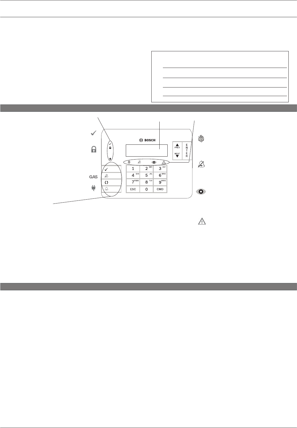
B925F Fire Keypad operating instructions
Operation
GAS
A1 Lobby
System Ready
RESET
SILENCE
ACK
DRILL
This keypad is a full-function system controller and
annunciator. The illuminated keypad has a display and a
sounder that emits distinct condition tones to alert you
to fi re alarm, fi re trouble, or fi re supervisory events as
they occur. In conjunction with the display and sounder,
seven status indicators provide the following system status
information as described below.
Required: Mount this document in view of the fi re
keypad.
Normal operation
When in normal operation and off (disarmed), the keypad shows programmed idle text, such as *Fire System*, or System
Ready.
Fire Alarm operation
When a fi rm alarm occurs, the Fire indicator lights, and the keypad emits a pulsing high-pitched fi re tone (____ ____ ____). The
tone sounds for the duration set by your security company. The keypad shows the fi rst point that entered alarm and its area.
Press ACK to acknowledge the alarm. The keypad shows the next point in alarm, if applicable. Press SILENCE to silence the
alarm.
Fire Trouble operation
When a trouble condition occurs (such as wiring for a point is cut or AC power fails), the keypad sounder activates briefl y
approximately every six seconds. The Trouble indicator lights and the keypad shows the highest priority trouble. Press ACK
to acknowledge the trouble. To view and acknowledge additional system or point troubles, press NEXT repeatedly.
Fire Supervisory operation
When a supervisory condition occurs, the sounder activates briefl y approximately every six seconds. The Supervisory
indicator lights and the keypad shows a fi re supervisory message. Press ACK to acknowledge the supervisory condition. To
view and acknowledge point supervisory conditions, press NEXT repeatedly.
Silence and reset
Alarm or Trouble silence. Press SILENCE and enter your passcode.
Detector reset. Press RESET and enter your passcode (if required). You can also use [CMD][4][7], or the Menu to
reset detectors.
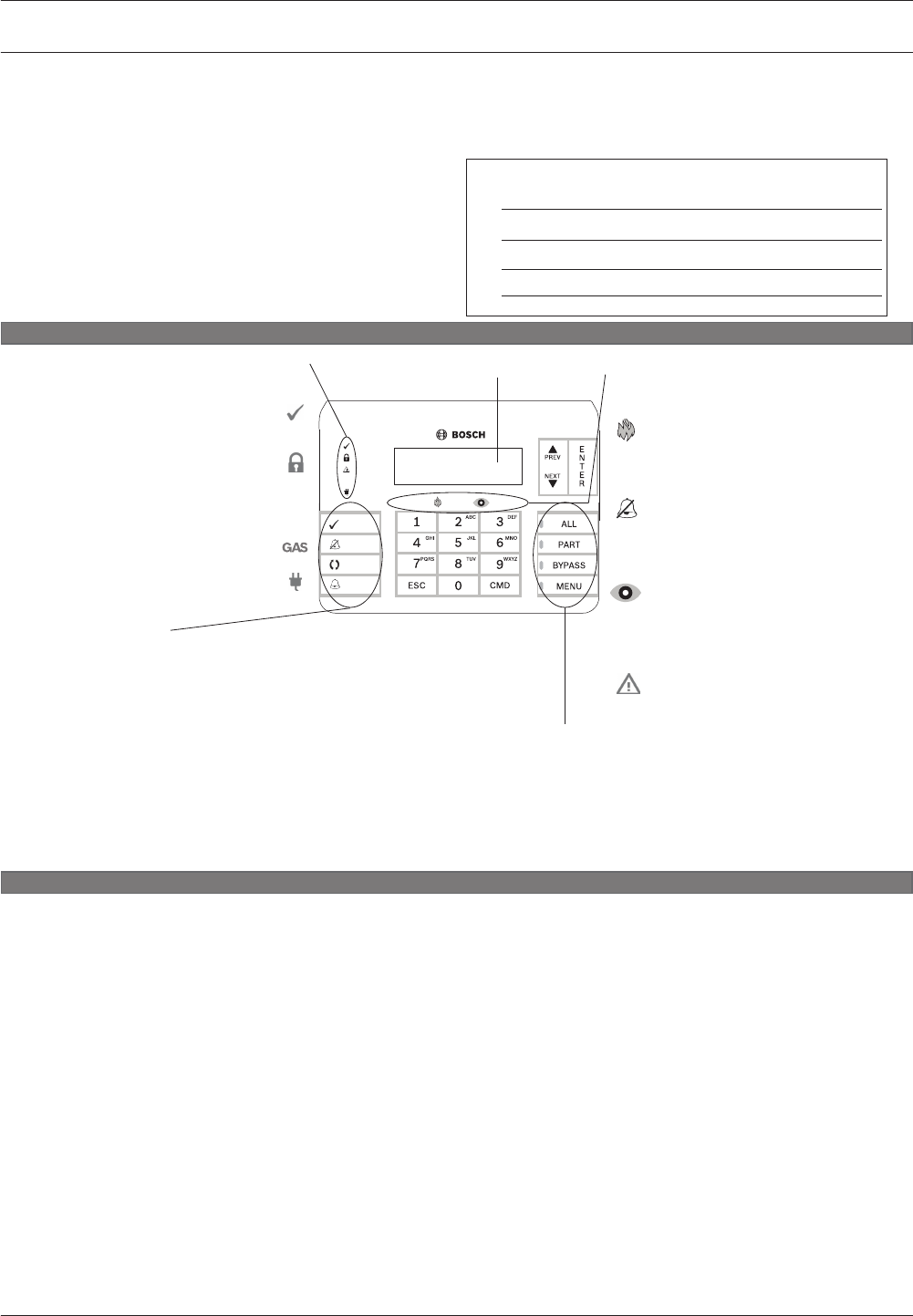
Overview
Local Service Representative
Name
Address
Phone
Status indicators
The Status indicators provide a quick
visual reference of the system status.
Fire function keys
ACK. Press to acknowledge the system alarm or trouble condition.
SILENCE. Press to silence fi re alarm or trouble.
RESET. Press to reset devices such as smoke detectors.
DRILL. Press and hold to initiate fi re drill.
Alphanumeric display
Navigation and number keys
The keypad includes keys for navigating and entering passcodes:
PREV and NEXT. Use to scroll through menus or menu selections.
ENTER. Use to complete the entry of your passcode or other
numbers, or to answer Yes to a keypad request.
backspace when you enter names and numbers.
ESC. Use to exit from menus and functions, or use as a
backspace when you enter names and numbers.
Number keys. Use to enter passcodes or other numbers and
letters.
Intrusion function keys
ALL. Press to turn the system All On.
PART. Press to turn the system Part On.
BYPASS. Press to open the menu to bypass points.
MENU. Press to open the keypad’s Main menu.
Fire
Lights when a fi re alarm
condition exists; turns off when
all fi re alarm points return to
normal.
Silenced
Lights when a fi re alarm condition
is silenced; turns off when a
user presses the RESET button
or if another fi re alarm condition
appears.
Supervisory
Lights when any point
programmed as supervisory is
not normal; turns off when all
supervisory points return to
normal.
Trouble
Lights when a trouble condition
exists.
Ready to arm
Lights when the system is ready
to turn on (arm).
On (armed)
Lights when the system is on
(armed).
Gas
Lights when a gas alarm exists.
Power
Lights to indicate the control
panel has AC power.
Fire Status indicators
The Fire Status indicators provide
a quick visual reference of the fi re
system status.
8
Control Panels B925F Fire Keypad operating instructions | en 33
Bosch Security Systems, Inc. UL Installation Guide 2016.05 | 05 | F.01U.304.001
B926F Fire Keypad operating instructions
Operation
This keypad is a full-function system controller and
annunciator. The illuminated keypad has a display and a
sounder that emits distinct condition tones to alert you
to fi re alarm, fi re trouble, or fi re supervisory events as
they occur. In conjunction with the display and sounder,
seven status indicators provide the following system status
information as described below.
Required: Mount this document in view of the fi re
keypad.
Normal operation
When in normal operation and off (disarmed), the keypad shows programmed idle text, such as *Fire System*, or System
Ready.
Fire Alarm operation
When a fi rm alarm occurs, the Fire indicator lights, and the keypad emits a pulsing high-pitched fi re tone (____ ____ ____). The
tone sounds for the duration set by your security company. The keypad shows the fi rst point that entered alarm and its area.
Press ACK to acknowledge the alarm. The keypad shows the next point in alarm, if applicable. Press SILENCE to silence the
alarm.
Fire Trouble operation
When a trouble condition occurs (such as wiring for a point is cut or AC power fails), the keypad sounder activates briefl y
approximately every six seconds. The Trouble indicator lights and the keypad shows the highest priority trouble. Press ACK
to acknowledge the trouble. To view and acknowledge additional system or point troubles, press NEXT repeatedly.
Fire Supervisory operation
When a supervisory condition occurs, the sounder activates briefl y approximately every six seconds. The Supervisory
indicator lights and the keypad shows a fi re supervisory message. Press ACK to acknowledge the supervisory condition. To
view and acknowledge point supervisory conditions, press NEXT repeatedly.
Silence and reset
Alarm or Trouble silence. Press SILENCE and enter your passcode.
Detector reset. Press RESET and enter your passcode (if required). You can also use [CMD][4][7], or the Menu to
reset detectors.
Overview
Local Service Representative
Name
Address
Phone
GAS
A1 Lobby
System Ready
RESET
SILENCE
ACK
DRILL
Status indicators
The Status indicators provide a quick
visual reference of the system status.
Fire function keys
ACK. Press to acknowledge the system alarm or trouble condition.
SILENCE. Press to silence fi re alarm or trouble.
RESET. Press to reset devices such as smoke detectors.
DRILL. Press and hold to initiate fi re drill.
Alphanumeric display
Navigation and number keys
The keypad includes keys for navigating and entering passcodes:
PREV and NEXT. Use to scroll through menus or menu selections.
ENTER. Use to complete the entry of your passcode or other
numbers, or to answer Yes to a keypad request.
backspace when you enter names and numbers.
ESC. Use to exit from menus and functions, or use as a
backspace when you enter names and numbers.
Number keys. Use to enter passcodes or other numbers and
letters.
Fire
Lights when a fi re alarm
condition exists; turns off when
all fi re alarm points return to
normal.
Silenced
Lights when a fi re alarm condition
is silenced; turns off when a
user presses the RESET button
or if another fi re alarm condition
appears.
Supervisory
Lights when any point
programmed as supervisory is
not normal; turns off when all
supervisory points return to
normal.
Trouble
Lights when a trouble condition
exists.
Ready to arm
Lights when the system is ready
to turn on (arm).
On (armed)
Lights when the system is on
(armed).
Gas
Lights when a gas alarm exists.
Power
Lights to indicate the control
panel has AC power.
Fire Status indicators
The Fire Status indicators provide
a quick visual reference of the fi re
system status.
9
34 en | B926F Fire Keypad operating instructions Control Panels
2016.05 | 05 | F.01U.304.001 UL Installation Guide Bosch Security Systems, Inc.
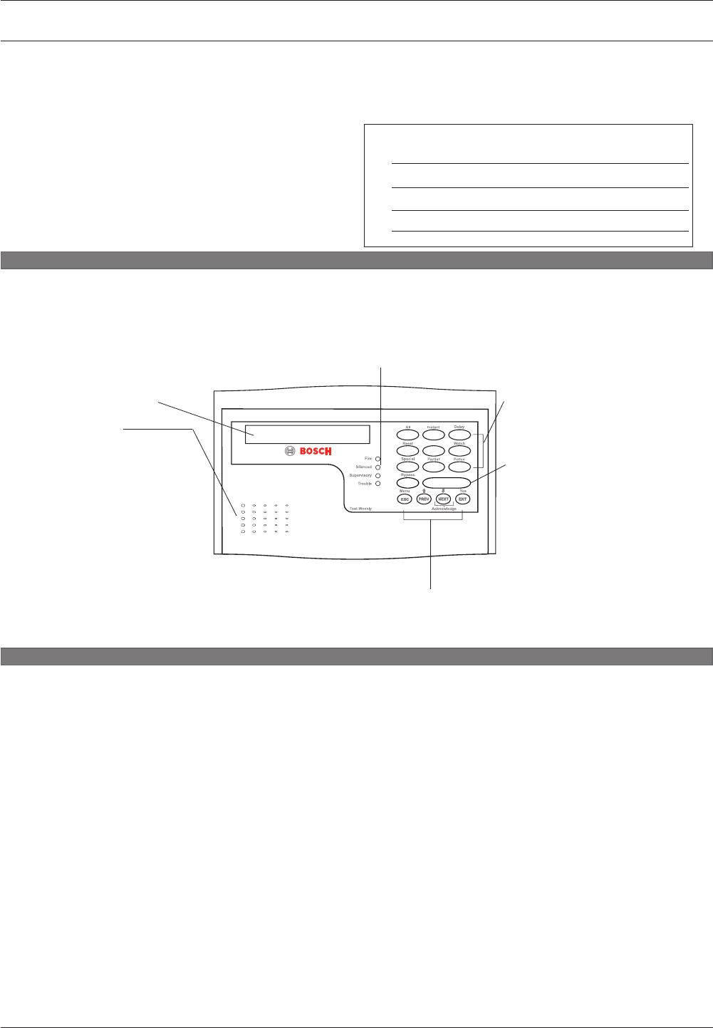
D1255RB operating instructions
Operation
This keypad is a system controller and annunciator. The
illuminated keypad has a 16-character vacuum fl uorescent
display (VFD) and a sounder that emits distinct condition
tones to alert you to fi re alarm, fi re trouble, or fi re supervisory
events as they occur. In conjunction with the VFD and the
sounder, four status LEDs provide the following system status
indications: Fire, Silenced, Supervisory, and Trouble.
Required: Mount this document in view of the fi re
keypad.
Normal operation
When the system is operating normally and is disarmed, the display shows the programmed idle text. The default system
normal message is * FIRE SYSTEM *.
Fire Alarm operation
When an alarm occurs, the Fire LED activates, and the keypad emits a pulsing high-pitched fi re tone. The tone sounds for a
pre-programmed length of time. A display message appears that describes the fi rst point that entered an alarm. Press the
NEXT key to acknowledge the alarm. To view and acknowledge additional points that are in alarm, press NEXT repeatedly.
The display shows Ax ## FIRE ALARM (x = the area number; ## = the number of fi re alarms in Area x).
Fire Trouble operation
When a trouble condition occurs (such as wiring for a point is cut, AC power fails, and so on), the keypad sounder activates
briefl y approximately every six seconds. The Trouble LED illuminates and Ax ## FIRE TRBL or the highest priority system
trouble appears in the display. Press the NEXT key to acknowledge the trouble. To view and acknowledge additional system
or point troubles, press NEXT repeatedly.
Fire Supervisory operation
Fire Supervisory Operation. When a supervisory condition occurs, the sounder activates briefl y approximately every six
seconds. The Supervisory LED illuminates and Ax ## FIRE SUPV appears in the display. Press the NEXT key to acknowledge
the supervisory condition. To view and acknowledge point supervisory conditions, press NEXT repeatedly.
Silence and reset
Alarm silence. Enter PIN (if required) and press ENT.
Trouble silence. Press the COMMAND bar and select 4.
Detector reset. Press the COMMAND bar and select 4 + 7.
Annunciating reset. Enter PIN (if required) and press ESC. This clears alarm or trouble memory from the keypad display,
when all points are in a normal state.
Overview
1
COMMAND
8
7
0
23
456
9
Navigation keys
Use ESC/Menu to enter the command menu, to complete a command entry, or to return to idle text.
Use PREV to return to the previously viewed menu item.
Use NEXT/Acknowledge to acknowledge an alarm or off -normal condition, or to move to the next menu item.
Use ENT/Yes to complete a PIN entry, or to select a menu item.
Local Service Representative
Name
Address
Phone
Alphanumeric display
Status indicators
The Status indicators provide a quick visual reference of the system status.
Fire: Lights when a fi re alarm condition exists; turns off when all fi re alarm points return to normal.
Silenced: Lights after a fi re alarm is silenced; turns off when a PIN and ESC is entered. This clears the alarm
or trouble memory from the keypad display, when all points are in a normal state.
Supervisory: Lights when any point programmed as supervisory is not normal; turns off when all supervisory
points return to normal.
Trouble: Lights when any system trouble or point trouble exists; turns off when the system and all points
return to normal.
Built-in sounder
The built-in sounder emits the
following warning tones:
Fire signal: pulsed, high-pitched
bell tone during fi re alarm.
Trouble signal: two-tone warble
during a trouble event.
Invalid key buzz: buzz tone when
invalid key is pressed.
Keypad encoding tone: muted
beep tone as each key is
pressed.
Number keys
Use one or two in combination
with the COMMAND bar to
perform a function, or use to enter
a PIN before pressing the ENT key.
COMMAND bar
Use in combination with one or
two numeric keys to perform a
function.
10
Control Panels D1255RB operating instructions | en 35
Bosch Security Systems, Inc. UL Installation Guide 2016.05 | 05 | F.01U.304.001

D1256RB operating instructions
Operation
This keypad is a system controller and annunciator. The
illuminated keypad has a 16-character vacuum fl uorescent
display (VFD) and a sounder that emits distinct condition
tones to alert you to fi re alarm, fi re trouble, or fi re supervisory
events as they occur. In conjunction with the VFD and the
sounder, four status LEDs provide the following system status
indications: Fire, Silenced, Supervisory, and Trouble.
Required: Mount this document in view of the fi re
keypad.
Normal operation
When the system is operating normally and is disarmed, the display shows the programmed idle text. The default system
normal message is * FIRE SYSTEM *.
Fire Alarm operation
When an alarm occurs, the Fire LED activates, and the keypad emits a pulsing high-pitched fi re tone. The tone sounds for a
pre-programmed length of time. A display message appears that describes the fi rst point that entered an alarm. Press the
NEXT key to acknowledge the alarm. To view and acknowledge additional points that are in alarm, press NEXT repeatedly.
The display shows Ax ## FIRE ALARM (x = the area number; ## = the number of fi re alarms in Area x).
Fire Trouble operation
When a trouble condition occurs (such as wiring for a point is cut, AC power fails, and so on), the keypad sounder activates
briefl y approximately every six seconds. The Trouble LED illuminates and Ax ## FIRE TRBL or the highest priority system
trouble appears in the display. Press the NEXT key to acknowledge the trouble. To view and acknowledge additional system
or point troubles, press NEXT repeatedly.
Fire Supervisory operation
Fire Supervisory Operation. When a supervisory condition occurs, the sounder activates briefl y approximately every six
seconds. The Supervisory LED illuminates and Ax ## FIRE SUPV appears in the display. Press the NEXT key to acknowledge
the supervisory condition. To view and acknowledge point supervisory conditions, press NEXT repeatedly.
Silence and reset
Alarm silence. Press the Alarm Silence key to silence a fi re alarm.
Trouble silence. Press the Trouble Silence key to silence a fi re trouble.
Detector reset. Press the Detector Reset key to reset detection devices.
Annunciating reset. Press the Annunciator Reset key to clear all alarm, trouble, and supervisory messages when all points
are in a normal state.
Overview
Navigation keys
Use ESC/Menu to enter the command menu, to complete a command entry, or to return to idle text.
Use PREV to return to the previously viewed menu item.
Use NEXT/Acknowledge to acknowledge an alarm or off -normal condition, or to move to the next menu item.
Use ENT to complete a PIN entry, or to select a menu item.
Local Service Representative
Name
Address
Phone
Alphanumeric display
Status indicators
The Status indicators provide a quick visual reference of the system status.
Fire:
Lights when a fi re alarm condition exists; turns off when all fi re alarm points return to normal.
Silenced: Lights after a fi re alarm is silenced; turns off when a PIN and ESC is entered. This clears the alarm
or trouble memory from the keypad display, when all points are in a normal state.
Supervisory: Lights when any point programmed as supervisory is not normal; turns off when all supervisory
points return to normal.
Trouble: Lights when any system trouble or point trouble exists; turns off when the system and all points
return to normal.
Built-in sounder
The built-in sounder emits the
following warning tones:
Fire signal. Pulsed, high-pitched
bell tone during fi re alarm.
Trouble signal. Two-tone warble
during a trouble event.
Invalid key buzz. Buzz tone when
invalid key is pressed.
Keypad encoding tone. Muted
beep tone as each key is
pressed.
Function keys
Use one or two in combination
with the COMMAND bar to
perform a function, or use to enter
a PIN before pressing the ENT key.
11
36 en | D1256RB operating instructions Control Panels
2016.05 | 05 | F.01U.304.001 UL Installation Guide Bosch Security Systems, Inc.

Specifications
Control panel power supply specifications
Voltage input
(power supply)
Primary Terminals
1
and 2
16.5 VAC 40 VA class 2 plug-in transformer (D1640)
Secondary Terminals
4
and 5
Use 12 VDC sealed lead-acid rechargeable battery (7 Ah, 18 Ah, or
38 Ah). The control panel supports up to 38 Ah of battery. If you
use two batteries, they must have the same capacity and you must
connect them using the D122/D122L Dual Battery Harness.
Current
requirements
Control Panel: Idle 190 mA; Alarm 265 mA
Refer to the Current Rating Chart for Standby Battery Calculations section in the Control Panels
(B9512G/B8512G) Installation and System Reference Guide for the current draw requirements
of other system components.
Power outputs2All external connections are power-limited except battery terminals.
Continuous
Power
Outputs
1.4 A maximum at 12.0 VDC nominal (continuous supply) total for all devices
and outputs including the ZONEX connection, the plug-in module connector,
and Terminals 3, 26, and 30.
Alarm Power
Output
2.0 A maximum (1.4 A max for commercial fire) at 12.0 VDC nominal output for
all devices and outputs including the ZONEX connection, the plug-in module
connector, and Terminals 3, 6, 7, 26, and 30. Output can be steady or one of
three pulsed patterns depending on programming. Refer to Relays in the
Online Help for RPS.
Switched
Aux Power
Terminal
8
1.4 A maximum at 12.0 VDC nominal output. Continuous output is
interrupted by Sensor Reset or alarm verification depending on
programming. Refer to Relays in RPS Help or the Control Panels
(B9512G/B8512G) Program Entry Guide.
Fire and
Fire/
Burglary
Systems
To comply with UL 985 and 864 listing standards for fire alarm systems
(effective March 1, 1989), the total combined continuous and alarm current
draw for the system during alarm conditions must be limited to 1.4 A provided
by the primary power supply (rectified AC). If current draw for the system
exceeds 1.4 A, remove connected devices until the current draw falls below
1.4 A. Then, connect the removed devices to an external power supply1 (such
as B520).
1 Requires a UL Listed power supply.
2 For UL 864 applications, refer to US1B LIt differences compatible devices.
Minimum
operating
voltage
10.2 VDC
SDI bus SDI bus A:
SDI bus B:
9 VDC 4572 m (15000 ft) maximum
9 VDC 4572 m (15000 ft) maximum
SDI2 bus SDI2 bus A:
SDI2 bus B:
12 VDC nominal (7500 ft) maximum2
12 VDC nominal (7500 ft) maximum2
12
Control Panels Specifications | en 37
Bosch Security Systems, Inc. UL Installation Guide 2016.05 | 05 | F.01U.304.001

Network Built-in 10/100 Ethernet LAN (RJ-45 connector)
USB USB 2.0 full speed
Environmental Temperature: 0°C to +49°C (+32°F to +120°F)
Relative
Humidity:
Maximum 93% non-condensing
Arming
stations
B942/B942W keypads, B930 keypads, B926F Fire keypads, B925F Fire keypads, B921C
keypads, B920, B915/B915I, D1260 keypads, D1257/D1257RB Fire Alarm Annunciators, D1256/
D1256RB, D1255/D1255R/D1255RB keypads, Keyswitch
Point
thresholds
(Single EOL
resistor circuit
style)
On-board
points 1 to 8
With 1.0 kΩ resistors Open - 3.7 to 5.0 VDC
Normal - 2.0 to 3.0 VDC
Short - 0.0 to 1.3 VDC
Short circuit current - 5 mA
With 2.0 kΩ resistors Open - 4.1 to 5.0 VDC
Normal – 3.0 to 4.1 VDC
Short - 0.0 to 3.0 VDC
Short circuit current - 5 mA
No EOL Open - 2.6 to 5.0 VDC
Short - 0.0 to 2.4 VDC
Short circuit current - 5 mA
Point
thresholds
(Dual EOL on-
board points)
Dual EOL (1.0 kΩ + 1.0 kΩ) Short - 0 to 1.67 VDC
Open - 4.12 to 4.95 VDC
Normal - 1.69 to 2.94 VDC
Fault - 2.95 to 4.10 VDC
Short circuit current - 5 mA
Compatible
enclosures
B8103 Universal Enclosure, D8103 Universal Enclosure, D8109 Fire Enclosure, D8108A Attack
Resistant Enclosure, BATB-40 and BATB-80 Battery Boxes.
Battery
discharge/
recharge
schedule
Discharge
Cycle
13.30 VDC
12.1 VDC
10.2 VDC
10.2 VDC
BATTERY STATUS LED slow flash.
Low Battery Report, if programmed.
BATTERY STATUS LED quick flash.
Minimum operational voltage.
Battery load shed.
Recharge
Cycle
AC ON
12.50 VDC (under
load)
13.4 VDC and charging
current < 200 mA
Load shed relay resets, battery charging begins.
Battery Restoral Report sent, BATTERY STATUS LED
off.
Battery float charged. BATTERY STATUS LED off.
Wire requirements
Terminal label Terminal description Requirements
1 AC 18 AWG min (up to 14 AWG max)
2 AC 18 AWG min (up to 14 AWG max)
12.1
38 en | Specifications Control Panels
2016.05 | 05 | F.01U.304.001 UL Installation Guide Bosch Security Systems, Inc.

3 + AUX POWER Terminal accommodates 14 to 22 AWG, use appropriate
wire size based on current
4 BATTERY - Bosch supplied wire lead, included with control panel.
5 BATTERY +
6 Output A (1) Terminal accommodates 14 to 22 AWG, use appropriate
wire size based on current
7 Output B (2)
8 Output C (3)
9 COMMON
10 EARTH GROUND 14 to 16 AWG
11 POINT 1 Terminal accommodates 14 to 22 AWG, use appropriate
wire size based on loop resistance less than 100 Ω
12 POINT 1/2 COMMON Terminal accommodates 14 to 22 AWG, use appropriate
wire size based on loop resistance less than 100 Ω
13 POINT 2 Terminal accommodates 14 to 22 AWG, use appropriate
wire size based on loop resistance less than 100 Ω
14 POINT 3 Terminal accommodates 14 to 22 AWG, use appropriate
wire size based on loop resistance less than 100 Ω
15 POINT 3/4 COMMON Terminal accommodates 14 to 22 AWG, use appropriate
wire size based on loop resistance less than 100 Ω
16 POINT 4 Terminal accommodates 14 to 22 AWG, use appropriate
wire size based on loop resistance less than 100 Ω
17 POINT 5 Terminal accommodates 14 to 22 AWG, use appropriate
wire size based on loop resistance less than 100 Ω
18 POINT 5/6 COMMON Terminal accommodates 14 to 22 AWG, use appropriate
wire size based on loop resistance less than 100 Ω
19 POINT 6 Terminal accommodates 14 to 22 AWG, use appropriate
wire size based on loop resistance less than 100 Ω
20 POINT 7 Terminal accommodates 14 to 22 AWG, use appropriate
wire size based on loop resistance less than 100 Ω
21 POINT 7/8 COMMON Terminal accommodates 14 to 22 AWG, use appropriate
wire size based on loop resistance less than 100 Ω
22 POINT 8 Terminal accommodates 14 to 22 AWG, use appropriate
wire size based on loop resistance less than 100 Ω
ZONEX ZONEX Bosch supplied wire, included with the optional B600
23 SDIx COMMON Terminal accommodates 14 to 22 AWG, use appropriate
wire size based on peripheral device current
24 SDIx DATA BUS B 22 AWG min (up to 14 AWG max)
25 SDIx DATA BUS A
Control Panels Specifications | en 39
Bosch Security Systems, Inc. UL Installation Guide 2016.05 | 05 | F.01U.304.001

26 SDIx POWER Terminal accommodates 14 to 22 AWG, use appropriate
wire size based on peripheral device current
27 SDI2 COMMON Terminal accommodates 14 to 22 AWG, use appropriate
wire size based on peripheral device current
28 SDI2 DATA BUS B 22 AWG min (up to 14 AWG max)
29 SDI2 DATA BUS A
30 SDI2 POWER Terminal accommodates 14 to 22 AWG, use appropriate
wire size based on peripheral device current
40 en | Specifications Control Panels
2016.05 | 05 | F.01U.304.001 UL Installation Guide Bosch Security Systems, Inc.

Bosch Security Systems, Inc.
130 Perinton Parkway
Fairport, NY 14450
USA
www.boschsecurity.com
© Bosch Security Systems, Inc., 2016
Bosch Sicherheitssysteme GmbH
Robert-Bosch-Ring 5
85630 Grasbrunn
Germany
www.boschsecurity.com
