Bosch FAP 520_OG_monob_ma Operation Manual 520 En US 1255597451
User Manual: Bosch Operation Manual FAP‑520 Automatic Fire Detectors LSN improved version
Open the PDF directly: View PDF ![]() .
.
Page Count: 38
- Table of Contents
- 1 Product Description
- 2 Planning Notes
- 3 Installation
- 4 Programming
- 5 Maintenance and Service
- 6 Technical Data
- A Appendix

Automatic Detectors LSN improved
version
FAP-O 520 | FAP-O 520-P | FAP-OC 520 | FAP-OC 520-P
en Operation Guide

Automatic Detectors LSN improved version Table of Contents | en 3
Bosch Sicherheitssysteme GmbH Operation Guide F.01U.025.877 | 2.1 | 2011.11
Table of Contents
1 Product Description 5
1.1 Performance Features 7
1.2 System Description 8
1.3 Configuration of the Detector 8
1.4 Functional Description of the Sensor Technology 9
1.5 LED Operation 9
2 Planning Notes 10
2.1 General Notes 10
2.2 Network Topologies for LSN Improved 10
3 Installation 12
3.1 Ceiling Mount Back Box 12
3.2 Detector Base/Detector Base with Relay 13
3.3 Address Allocation 16
3.4 Detector and Trim Ring 16
3.5 Built-in Housing for Concrete Ceilings 18
3.6 Surface Mount Back Box 19
3.7 External Detector Alarm Displays 20
3.7.1 Mounting Notes for the Remote Indicator FAA-420-RI 20
3.7.2 Mounting Notes for the External Detector Alarm Display MPA 22
4Programming 24
5 Maintenance and Service 26
5.1 Notes for the Service 27
5.2 General Notes for Detector Testing 27
5.3 Inspection Procedure for FAP-OC 520 28
5.3.1 1. Alternative 28
5.3.2 2. Alternative 28
5.4 Inspection Procedure for FAP-O 520 29
5.4.1 1. Alternative 29
5.4.2 2. Alternative 29
5.5 Repair 30
5.6 Disposal 30
5.7 Additional Documentation 30
6 Technical Data 31
6.1 Detector and Trim Ring 31
6.2 Detector Base 32
6.3 Mounting Boxes 32
6.4 External Detector Alarm Displays 33

4en | Table of Contents Automatic Detectors LSN improved version
F.01U.025.877 | 2.1 | 2011.11 Operation Guide Bosch Sicherheitssysteme GmbH
A Appendix 34
A.1 Abbreviations 34
A.2 Order Overview 34
A.2.1 Detector and Trim Ring 34
A.2.2 Detector Bases/Accessories 35
A.2.3 Mounting Boxes 35
A.2.4 Service/Hardware Accessories 35

Automatic Detectors LSN improved version Product Description | en 5
Bosch Sicherheitssysteme GmbH Operation Guide F.01U.025.877 | 2.1 | 2011.11
1 Product Description
Figure 1.1 520 Series Fire Detector
The 520 Series Fire Detectors combine the advantages of the LSN improved technology with
the aesthetic benefits of flush-mounted installation and the option to choose the color. The
detectors are specially designed for connection to the modular fire panel Series 5000 with the
significantly extended LSN system parameters. They can also be connected to all classic LSN
fire panels.
The detectors with associated trim ring are available in the versions white and transparent
with color toning inserts. Through the use of the supplied color toning inserts, optimum
adjustment to many different environments becomes possible.
The lack of an optical labyrinth and their easily-cleaned smooth surface means the detectors
are also suitable for applications in high-dust areas.
The low profile, flush-mounted design allows the use the detectors even in areas that must be
free of protrusions.
Thanks to the geometric arrangement of two separate optical sensor systems, the detectors
are not sensitive to interference, such as that caused by insects. The scattered light volume
that is evaluated by the sensors is located in the free space a few centimeters below the
ceiling.
The contamination level is measured constantly. Contamination of the detector surface leads
to an active adjustment of the threshold (drift compensation) and a fault indication at the
panel in the case of heavier contamination.
The detector is available as a scattered light fire detector only or as a multisensor detector
with an additional gas sensor.
The combination of scattered light detector and gas sensor allows the evaluation of signals
with the help of modern signal processing methods. The result is high immunity against
deceptive alarms and extended application possibilities in environments that are not suitable
for pure scattered light smoke detectors.
The integrated rotary switches allow for an automatic or manual allocation of addresses.
The FAP-520 Detectors can be connected directly to the Local SecurityNetwork LSN.
Accessories
The 520 Series Detectors are generally mounted flush with the ceiling in false ceilings. The
detector and base are installed in a robust ceiling mount back box. In addition, a housing for
mounting within concrete ceilings can be used.
For special applications where recessed ceiling mounting is not possible, a surface mount
back box is available. This is used as an alternative to the ceiling mount back box.
The surface mount back box with damp room seal also allows the detector to be used in a
humid environment.
6en | Product Description Automatic Detectors LSN improved version
F.01U.025.877 | 2.1 | 2011.11 Operation Guide Bosch Sicherheitssysteme GmbH
For special applications, e.g. control of an emergency door in accordance with DIBt, base
variants are available with relay (only in combination with the Modular Fire Panel FPA-5000).
All bases have an integrated strain relief for false ceiling cables.The connection terminals are
easily accessible. Cables up to 3.3 mm2 in cross section can be used.
An innovative concept for locking the detector module utilizing the push-in/push-out principle
allows very quick and easy insertion and exchange of the click and lock detector.
For the detector test and detector exchange, a special user-friendly service accessory is
available.
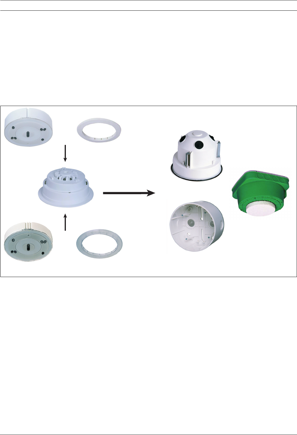
Overview of the 520 Series Detectors and Accessories
Figure 1.2 520 Series Detectors and Accessories
Detectors LSN improved:
LSN Detector Bases:
FAP-O 520-P
FAP-OC 520-P
FAP-O 520
FAP-OC 520
FAA-500
FAA-500-R
FAA-500-BB
FAA-500-CB
FAA-500-SB-H
FAA-500-TR-W
+
+
FAA-500-TR-P
- FAP-O 520 Optical Fire Detector LSN improved, white
- FAP-O 520-P Optical Fire Detector LSN improved, transparent with color toning
inserts
- FAP-OC 520 Multisensor Fire Detector LSN improved, optical/chemical, white
- FAP-OC 520-P Multisensor Fire Detector LSN improved, optical/chemical, transparent
with color toning inserts
- FAA-500-TR-W White Trim Ring for detectors 500 and 520 Series
- FAA-500-TR-P Transparent Trim Ring with color toning inserts for detectors 500 and
520 Series
- FAA-500 LSN Detector Base
- FAA-500-R LSN Detector Base with Relay*
* for connection to the Modular Fire Panel FPA-5000 only

Automatic Detectors LSN improved version Product Description | en 7
Bosch Sicherheitssysteme GmbH Operation Guide F.01U.025.877 | 2.1 | 2011.11
Mounting Boxes:
Service Accessories:
1.1 Performance Features
– Fulfills the highest aesthetic demands through the flush-mounting design and the
possibility of color toning
– Smooth, easily-cleaned detector surface
– Quick and easy insertion and exchange of the detector thanks to innovative detector
locking mechanism (click and lock principle)
– Easily-visible two-color LED for display of alarm, trouble and test mode
– Self-monitoring of the sensors, with display on the fire panel:
– Fault indication upon failure of the evaluation electronics or one of the LEDs of the
optical sensor
– Three-stage contamination display (analog value can be read out at service)
– Fault indication in the case of heavy contamination (instead of false alarm)
– Fault indication in the case of CO sensor failure (for the FAP-OC 520)
– Thanks to integrated isolators, the LSN loop will continue to function in case of wire
interruption or short-circuit of a detector
– Active adjustment of the threshold (drift compensation) if the optical sensor becomes
contaminated
– Active adjustment of the threshold (drift compensation) of the chemical sensor
– Increased detection and false alarm immunity thanks to evaluation of the time behavior
of fire and disturbance variables
– Programmable sensitivity, i.e. can be adjusted to the area of operation
– Flexible network structures, including T-taping without additional elements
– Automatic or manual address allocation with or without auto-detection via integrated
rotary switches
– Detector individual identification on the fire panel in the case of alarm
– A pre-alarm is signaled when 50 % of alarm threshold is reached (indicator in the event
database of the fire panel).
– Serial number, contamination level, operating hours and current analog values can be
read out from each configured detector
– Activation of an external detector alarm display is possible (not for relay bases)
– Activation of external devices by the relay base is possible (only in combination with the
Modular Fire Panel FPA-5000)
– Easily-accessible connection terminals
– Service accessories for simple and comfortable detector test and exchange
– When using the FAA-500-TTL test adapter, an integrated reed switch automatically
switches the detector into the test mode.
– The EMC security fulfills the guidelines according to VdS 2110 (VdS Schadenverhütung
GmbH) as well as UL 268.
- FAA-500-BB Ceiling Mount Back Box
- FAA-500-CB Built-in Housing for concrete ceilings
- FAA-500-SB-H Surface Mount Back Box with damp room seal
- FAA-500-RTL Detector Exchanger for 500 and 520 Series Detectors
- FAA-500-TTL Test Adapter with Magnet for 500 and 520 Series Detectors
8en | Product Description Automatic Detectors LSN improved version
F.01U.025.877 | 2.1 | 2011.11 Operation Guide Bosch Sicherheitssysteme GmbH
– Can be connected to the LSN fire panels FPA-1200, FPA-5000, BZ 500 LSN,
UEZ 2000 LSN, UGM 2020 and to other fire panels or their receiver modules with
identical connection conditions.
– VdS Approval
– CE conform according to EN 54-7
1.2 System Description
All detectors in the 520 Series are equipped with two optical sensors and a pollution sensor.
The FAP-OC 520 Multisensor Detector contains a gas sensor as an additional detection
channel.
The response sensitivity of the detector can be programmed with the programming software
via the LSN network. All sensor signals are analyzed continually by the internal signal
evaluation processor and are linked with each other.
By linking the optical sensors and the gas sensor, the OC detector can also be used in places
where the work carried out gives rise to small amounts of smoke, steam or dust. The alarm
will only be triggered automatically if the signal combination corresponds with the
characteristic diagram of the installation location that was selected during configuring.
1.3 Configuration of the Detector
Figure 1.3 Detector front panel with sensors
Figure 1.4 Side view of detector cover
Position Description Position Description
1 Optical sensor 5 Two-color LED:
red = alarm
green = test mode / trouble
2 Receiver (photo diodes) 6 Pollution sensor
3 Transmitter (LEDs) 7 Measuring area
4 CO sensor (only OC-variants)
1 1
2
3
3
2
4
5
6
23
7

Automatic Detectors LSN improved version Product Description | en 9
Bosch Sicherheitssysteme GmbH Operation Guide F.01U.025.877 | 2.1 | 2011.11
1.4 Functional Description of the Sensor Technology
Optical sensor (smoke sensor)
The optical sensor (see Figure 1.3 (1)) operates according to the scattered light principle.
The LEDs (see Figure 1.3 (3)) transmit light at a defined angle into the measuring area (see
Figure 1.4 (7)). In case of fire, the light is scattered by the smoke particles and strikes the
photo diodes (see Figure 1.3 (2)), which transform the quantity of light into a proportional
electrical signal.
The effects of daylight and commercial lighting sources are filtered out with an optical
daylight filter and by the use of electronic filtering and phase-locked rectification (ambient
light stability: glare test DIN EN 54-7).
The various light-emitting and photo diodes of the detector are individually activated.
Consequently, signal combinations are produced that are independent of each other and
ideally suitable for the detection of smoke, which makes it possible to differentiate between
smoke and interference agents (insects, objects). In addition, the time characteristics and the
correlation of the optical sensor signals for the fire or interference detection are evaluated.
Moreover, plausibility checking of the various signals makes it possible to detect errors in the
evaluation electronics and the LEDs.
Chemical sensor (CO gas sensor)
The gas sensor (see Figure 1.3 (4), only FAP-OC 520(-P)) detects mainly the carbon monoxide
(CO) that is produced by a fire, but it also detects hydrogen (H) and nitrogen monoxide (NO).
The basic measuring principle is CO oxidation on an electrode and the measurable current
that arises from this. The sensor signal value is proportional to the concentration of gas.The
gas sensor supplies additional information in order to reliably suppress the disturbance
variables.
The CO sensor is monitored by supervision of the internal capacity. If the capacity lies outside
the permitted range, a malfunction signal is output on the fire panel. In this case, the detector
continues to operate purely as a scattered light smoke detector.
Pollution sensor
The contamination level of the detector surface is measured and evaluated continuously by
the pollution sensor (see Figure 1.3 (6)). A three-stage contamination display can be read out
at service (see Section 5 Maintenance and Service, page 26).
1.5 LED Operation
The two-color LED of the detector indicates the operation and alarm statuses.
During the whole life cycle, the sensors are self-monitored and the sensitivity is self-adjusted
according to the programmed threshold. In case the detector is heavily contaminated, a
message is sent to the fire panel.
In case of an alarm, the LED flashes red. The detector is set back to standby if the alarm is
reset via the fire panel and if the cause of the alarm is gone.
LED Operation
Status LED
Standby off
Alarm red, flashes
Trouble green, double flash every 8 to 12 seconds
Test mode green, flashes once every second

10 en | Planning Notes Automatic Detectors LSN improved version
F.01U.025.877 | 2.1 | 2011.11 Operation Guide Bosch Sicherheitssysteme GmbH
2 Planning Notes
2.1 General Notes
– Country-specific standards and guidelines must be observed during the planning phase.
– The FAP-OC 520, like the FAP-O 520, is planned according to the guidelines for optical
detectors (see also EN 54 and VDS 2095).
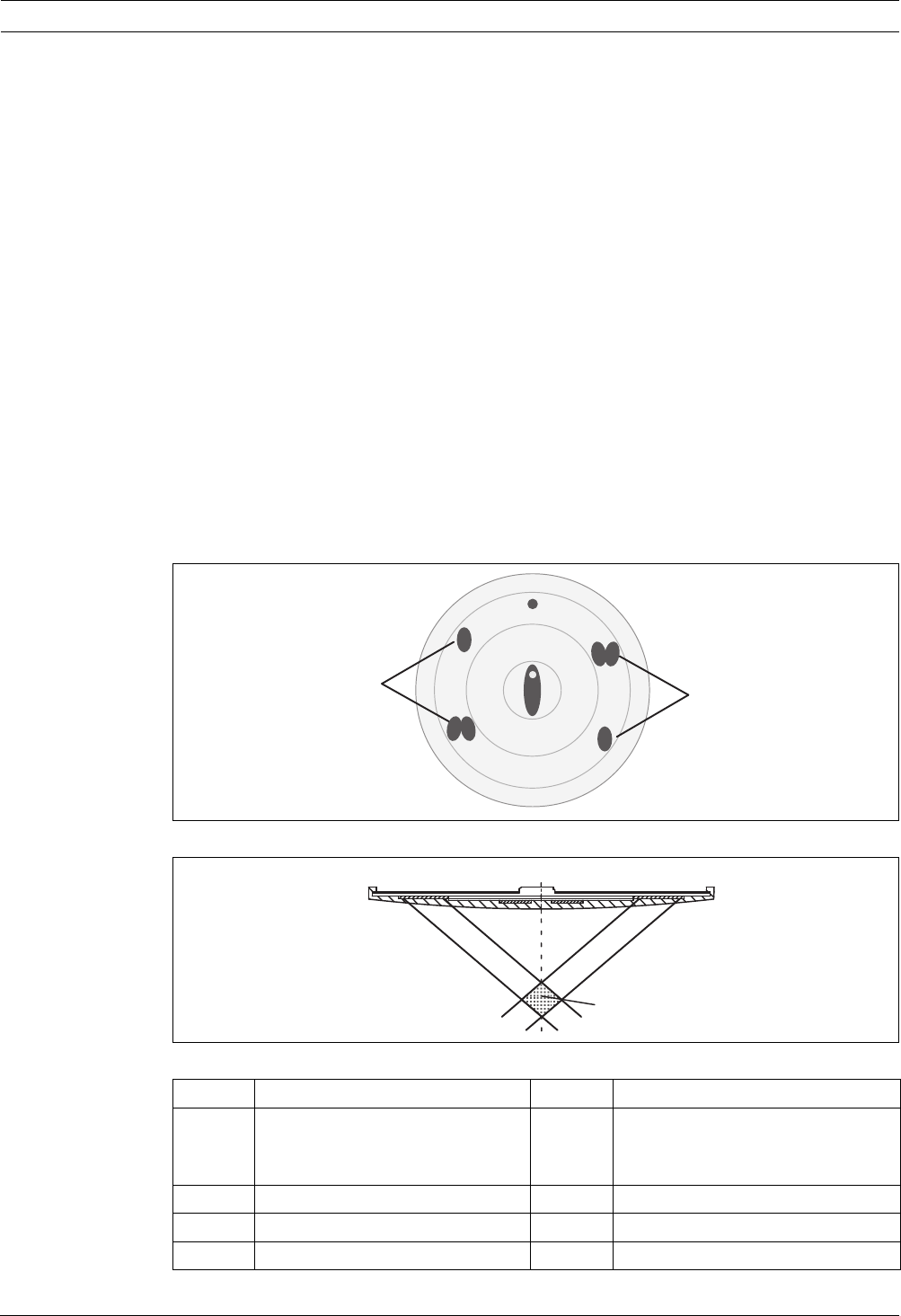
– A hemispherical space (see Figure 2.1 (1)) with a radius of 50 cm must remain free below
the detector (see Figure 2.1 (2)).
Care must be taken to ensure that no people, larger animals, plants, opening doors or
any objects intrude into this area and that no parts of the detector surface become
covered.
Figure 2.1 Radius
– The detector may only be installed in a position which is out of arm's reach.
Minimum installation height recommended by BOSCH: 2.70 m.
– The 520 Series Detectors may not be installed in rooms with data transmission by means
of high-intensity infra-red light (e.g. in rooms with IR systems for interpreters).
– The detectors must be mounted so that they are not exposed to any direct sunlight.
– A minimum distance of 50 cm from lamps must be maintained.
The detectors may not be mounted in a cone of light from lamps.
– By default, the bases are equipped with a spring for mounting the detector in concrete
and wooden ceilings. This spring is identifiable by the red marking. For mounting a
detector in a false ceiling panel you can use the additional, softer spring in the package.
In this use case, the detector must not be subjected to strong vibrations (> 350 m/s).
– Maximum permitted air speed: 20 m/s.
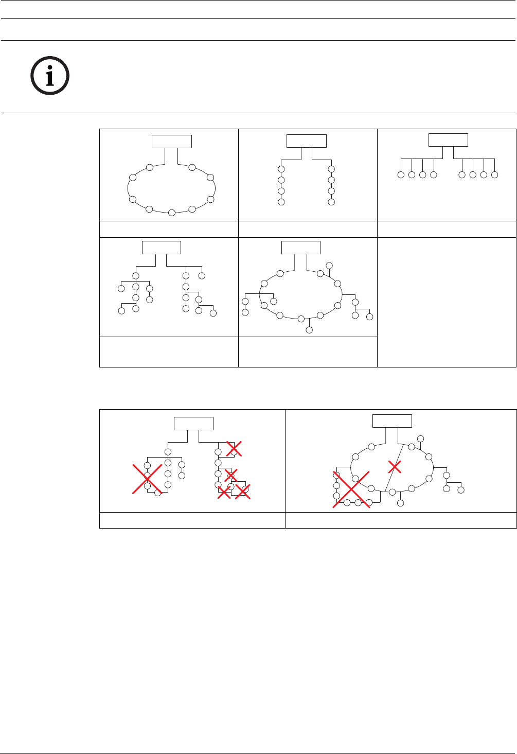
2.2 Network Topologies for LSN Improved
In an improved version Local Security Network (LSN improved), the detectors can be
configured as a loop, a stub or T-tap or in any mixed loop or T-tap structures. However, it is
important to note that mesh structures cannot be created.
The LSN improved version allows T-taps on stubs or loops and any number of nodes, branches
per node and elements per branch as long as the maximum number of elements does not
exceed 254.
Connections can be positioned anywhere along the LSN line.
NOTICE!
The 520 Series Detectors are approved for indoor use only! The detectors must be installed
exclusively in the FAA-500 Series Bases provided. In addition, the detector base must be
installed in an FAA-500-BB Ceiling Mount Back Box or in an FAA-500-SB-H Surface Mount Back
Box.
1
50 cm
2
Automatic Detectors LSN improved version Planning Notes | en 11
Bosch Sicherheitssysteme GmbH Operation Guide F.01U.025.877 | 2.1 | 2011.11
Table 2.1 Possible structures in LSN
When configuring the detectors, it is essential to ensure that no mesh structures are created.
Table 2.2 Unusable network structures
NOTICE!
Planning should take the anticipated total current and line resistance into account to ensure
each detector has an operating voltage of at least 15 V DC.
As soon as an LSN classic device is in a loop or stub, only loop or stub structures can be used.
In this case, T-tapping is no longer possible.
1: Loop 2: 1 or 2 stubs 3: T-tap
4: 1 or 2 stubs and T-taps
mixed
5: Loop and stubs mixed with
T-taps
Mesh structures within a stub structure Mesh structures within a loop structure
FPA-5000
FPA-5000
FPA-5000
FPA-5000
FPA-5000
FPA-5000
FPA-5000

12 en | Installation Automatic Detectors LSN improved version
F.01U.025.877 | 2.1 | 2011.11 Operation Guide Bosch Sicherheitssysteme GmbH
3 Installation
3.1 Ceiling Mount Back Box
Figure 3.1 Ceiling mount back box
The ceiling mount back box (see Figure 3.1) is made of white polypropylene.
It has four cable bushings with tightly-closing rubbers lips of polyflam that are suitable for
cable diameters up to 1.4 cm.
When used with a base, approx. 30 cm of cable length can be accommodated in the upper
area of the ceiling mount back box.
1. Bore a circular hole with a diameter of 130 mm (tolerance -1 mm to +5 mm) in the false
ceiling.
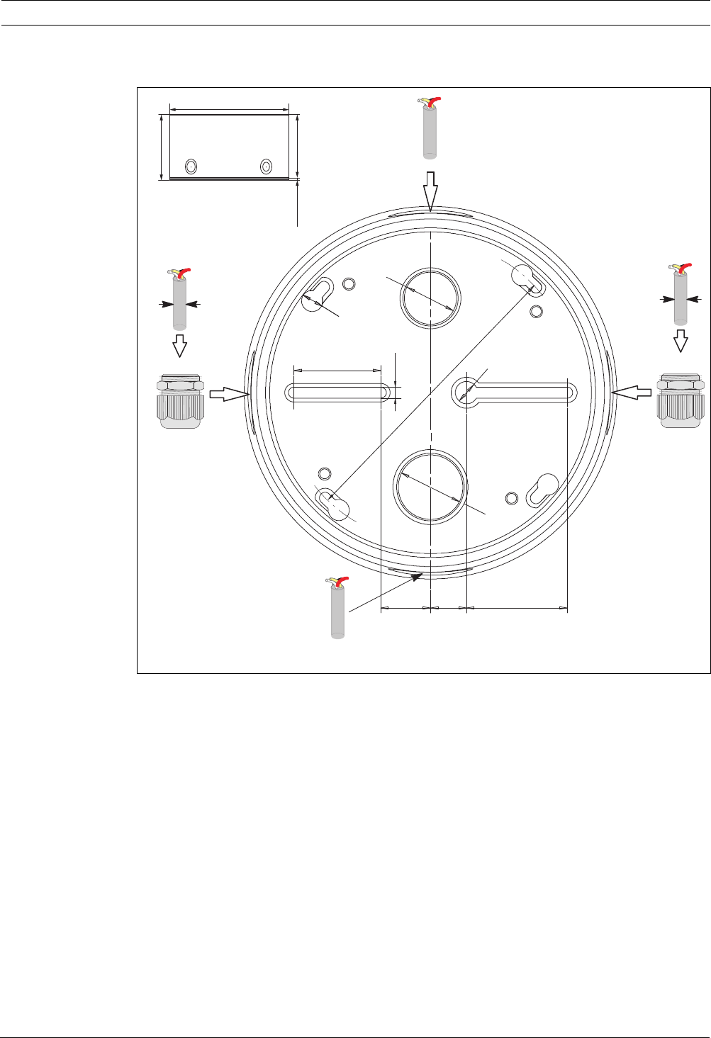
Figure 3.2 Plan view and side view of the ceiling mount back box FAA-500-BB
NOTICE!
The 520 Series Detectors may only be installed with an FAA-500 Detector Base in combination
with an FAA-500-BB Ceiling Mount Back Box or an FAA-500-SB-H Surface Mount Back Box.
NOTICE!
The false ceiling may have a maximum thickness of 32 mm.
Above the false ceiling, a free height of at least 11 cm is required.
NOTICE!
A hole saw with Ø 133 mm can be obtained from:
Wittmann-Komet, Metal Cutting Saws GmbH & Co. KG, Alte Str. 28, D-79576 Weil am Rhein,
Tel. ++49-7621-9783-0, www.wittmann-komet.de
129 mm
104 mm
3
1
2

Automatic Detectors LSN improved version Installation | en 13
Bosch Sicherheitssysteme GmbH Operation Guide F.01U.025.877 | 2.1 | 2011.11
2. Pull the cable through one of the cable bushings (see Figure 3.2 (3)). A cable tie around
the cable sheath will secure the cable against being pulled out accidentally.
3. Insert the ceiling mount back box in the false ceiling from below.
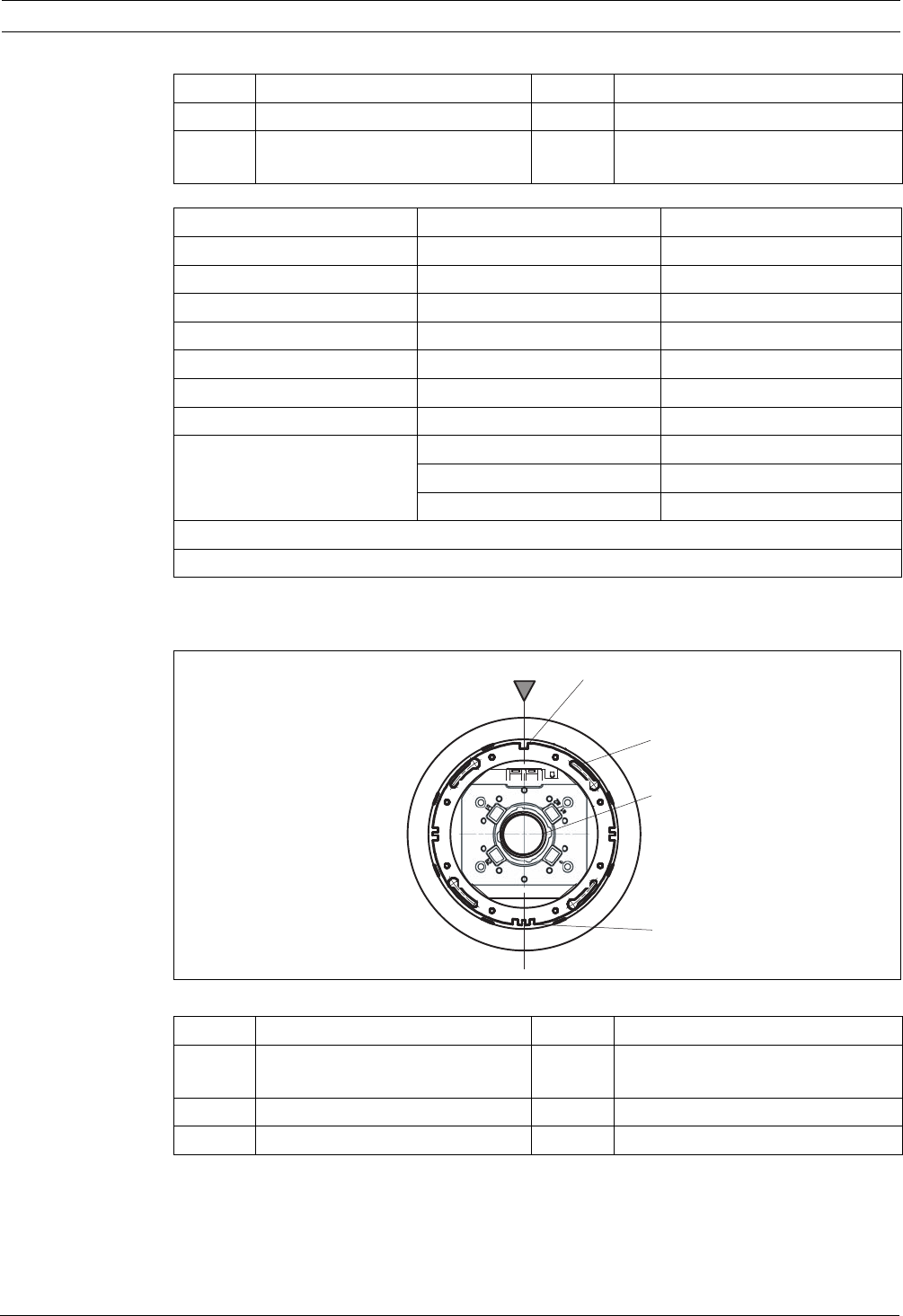
4. A triangular marking (see Figure 3.3 Pos. M) is impressed into the outer edge of the
ceiling mount back box. Turn the ceiling mount back boxes so that all markings are in a
line. In this way, the long, middle windows of the detectors will later appear in a line to
give a harmonious overall visual effect.
5. Tighten the brackets (see Figure 3.2 (1)).
Figure 3.3 Alignment of ceiling mount back box, base and detector
3.2 Detector Base/Detector Base with Relay
Figure 3.4 Side view of base
The base housings (see Figure 3.4) are made of white polycarbonate.
The screw terminals (for cables with cross section from 0.3 mm2 to 3.3 mm2) guarantee a
secure electrical connection through the clamped contacts when mounting the detector. The
bases are provided with three mounts for cable ties. These can be used for fastening the base
during the wiring-up.
Position Description Position Description
1 Bracket 3 Cable bushing
2 Screws for fastening base
E
NOTICE!
It is recommended that for the usual, soft false ceiling panels, you do not use a cordless
screwdriver.
FAA-500-BB FAA-500
FAP-O 520 (-P)
FAP-OC 520 (-P)
M
LED
mm
5
,36
146 mm
14 en | Installation Automatic Detectors LSN improved version
F.01U.025.877 | 2.1 | 2011.11 Operation Guide Bosch Sicherheitssysteme GmbH
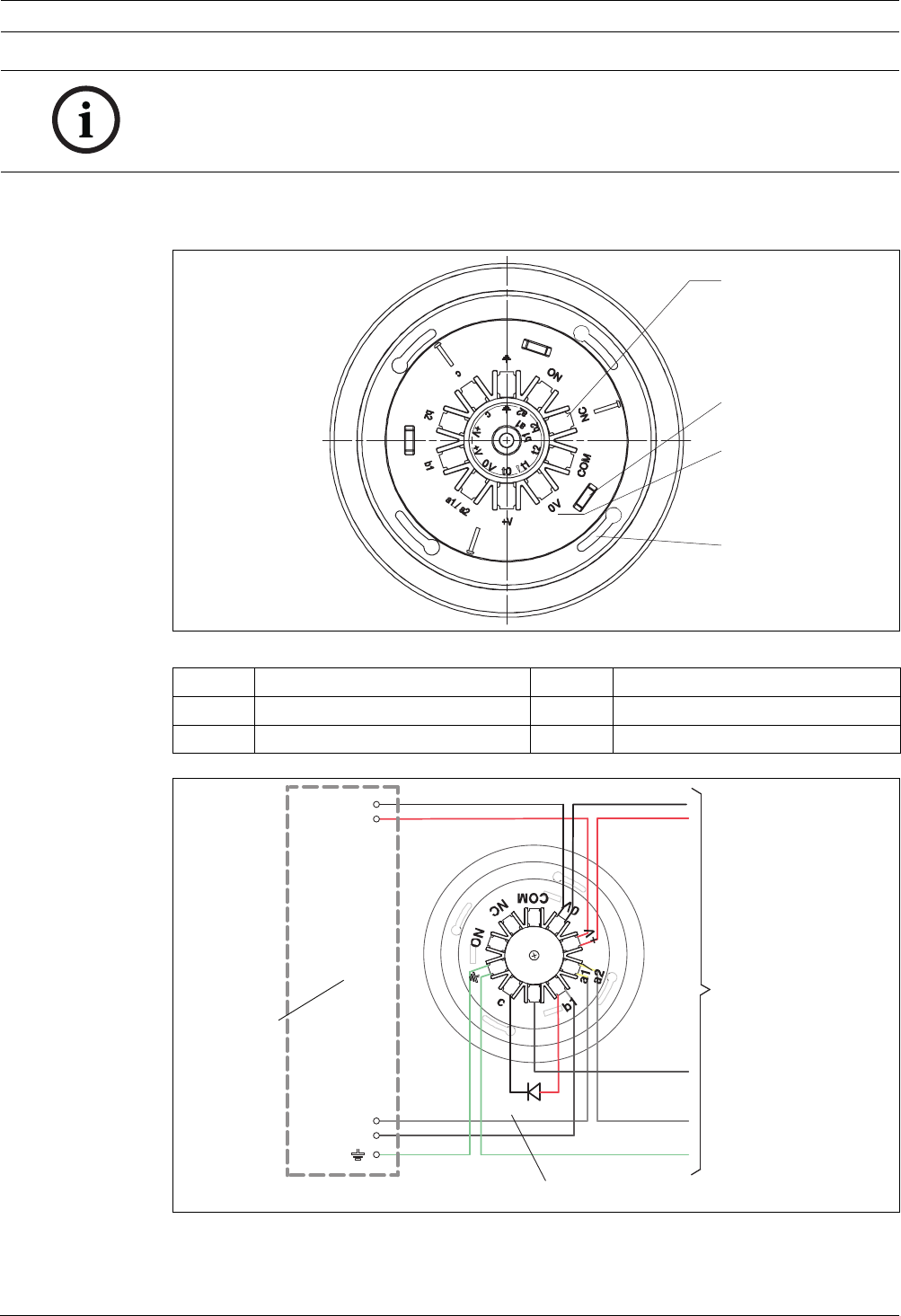
Connecting the base
Wire up the LSN base according to the labeling in the outer ring (see Figure 3.5 (3)).
Figure 3.5 Plan view base
Figure 3.6 Connection of bases
NOTICE!
Detector bases with relay (FAA-500-R) can only be used in combination with the modular fire
panel series 1200 and 5000.
In cases where relay bases are used, no external detector alarm display can be connected.
Position Description Position Description
1 Connection terminals 3 Labeling on LSN connections
2 Mount for cable ties 4 Fastening slot
1
2
3
4
MPA
+V
0V
LSN a1/a2
LSN b1
wh wh
gn
rd rd
bk
ye
ye
b2
FAA-500(-R)
gn
bk
3
2
1
Automatic Detectors LSN improved version Installation | en 15
Bosch Sicherheitssysteme GmbH Operation Guide F.01U.025.877 | 2.1 | 2011.11
The base is fastened into the ceiling mount back box with four screws. It can be rotated in the
long slots through an angle of 20° so that fine alignment is possible.
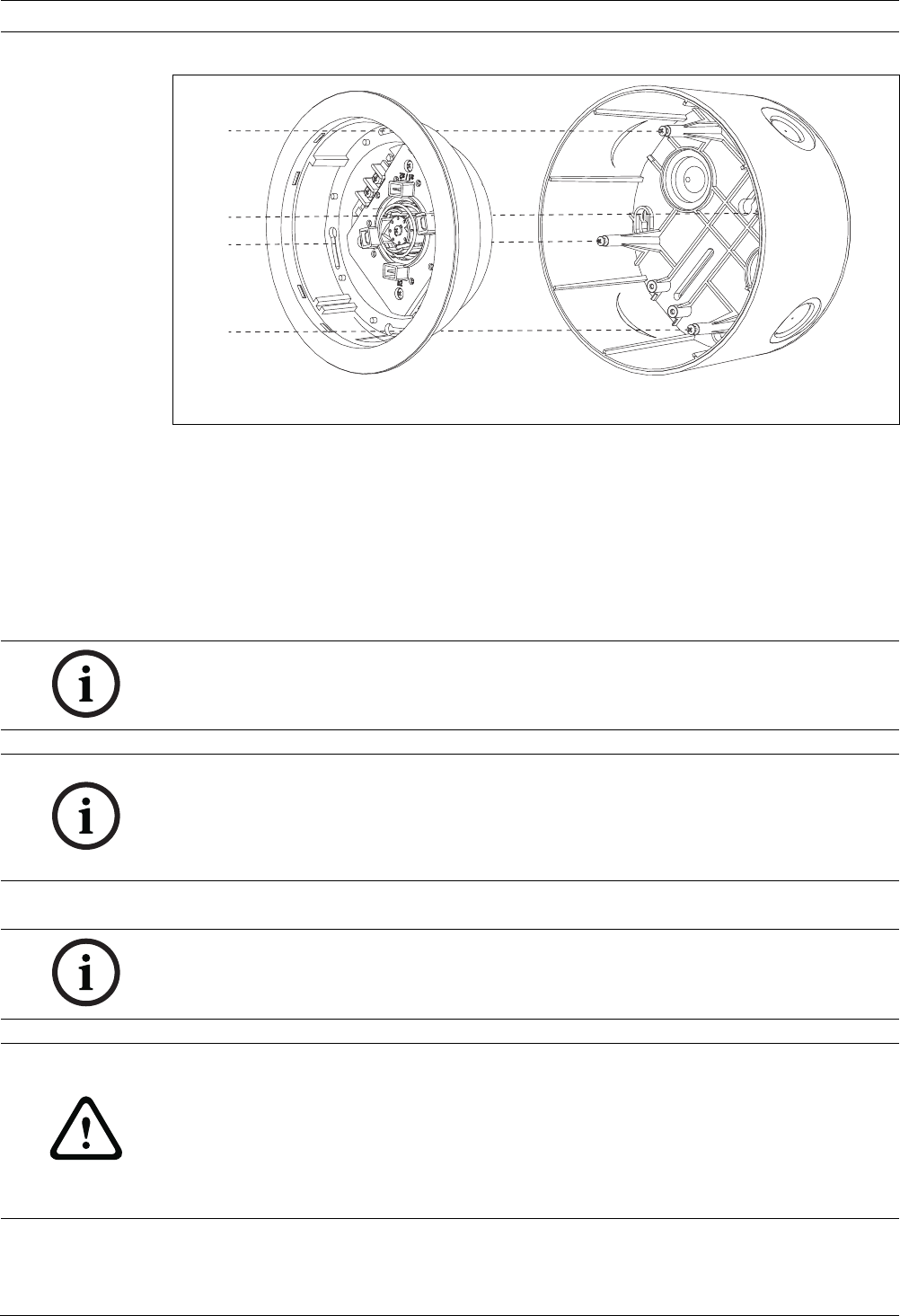
Figure 3.7 Placing the base in the ceiling mount back box
1. Place the base in the ceiling mount back box so that the marking on the backbox (see
Figure 3.7 (1)) coincides with the single guide-groove on the base (2).
2. Turn the base until the fastening screws are approximately in the middle of the long slots
(3).
3. Adjust the bases around this position until they appear in a line.
Position Description Position Description
1 Fire panel 3 Next detector
2 External detector alarm display
(optional), not for relay bases
Connection Terminal Wire
Voltage - * 0V black (bk)
Voltage + * +V red (rd)
LSN a in/out a1/a2 white (wh)
LSN b in b1 yellow (ye)
LSN b out b2 yellow (ye)
Indicator output c
Shielding [green (gn)]
Relay outputs** (FAA-500-R) NO
NC
COM
* Terminals for looping through the power supply for other LSN elements
**For connection to FPA-1200/FPA-5000 only
Position Description Position Description
1 Alignment of the marking on the
ceiling mount back box
4Spring
2 Single guide-groove 5 Triple guide-groove
3 Long slot for fastening the base
1 2
3
4
5
16 en | Installation Automatic Detectors LSN improved version
F.01U.025.877 | 2.1 | 2011.11 Operation Guide Bosch Sicherheitssysteme GmbH
4. Tighten the four screws.
3.3 Address Allocation
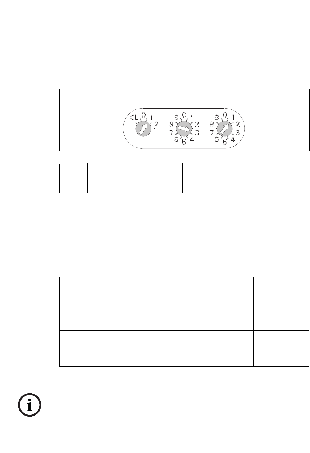
The detector's address is allocated by setting three rotary switches located on the back of the
device.
Use a flat-bladed screwdriver to position each switch. The switches will click when turned.
All detectors delivered ex factory are set to 0 0 0.
Figure 3.8 Rotary switches
When connecting the detectors to the LSN fire panels BZ 500 LSN, UEZ 2000 LSN or
UGM 2020, all detectors have to be addressed by CL 0 0.
When connecting the detectors to the Modular Fire Panel FPA1200/FPA-5000, the address
allocation is done automatically or manually.
In case of a manual allocation, all detectors of the same loop, stub or T-tap have to have an
address between 001 and 254. Addresses between 255 and 299 are not allowed and produce
a fault message on the fire panel.
If the addresses shall be allocated automatically by the fire panel, all detectors must have the
address 0 0 0.
3.4 Detector and Trim Ring
Position Description Position Description
CL LSN classic mode xXx Tens
Xxx Hundreds xxX Ones
Address Operating mode Fire Panel
CL 0 0 Loop/stub in classic LSN mode BZ 500 LSN
UEZ 2000 LSN
UGM 2020
FPA 1200
FPA 5000
0 0 1 - 2 5 4 Loop/stub/T-tap system in LSN improved mode with
manual addressing
FPA 1200
FPA 5000
0 0 0 Loop/stub in LSN improved mode with automatic
addressing (T-tap system not possible)
FPA 1200
FPA 5000
CL/
Xxx xXx xxX
NOTICE!
The packaging of the detectors with C sensor consists of tear-resistant PE-ALU laminated film
and must be cut open carefully.
Do not remove the protective film until the detector is ready to be fitted.
Automatic Detectors LSN improved version Installation | en 17
Bosch Sicherheitssysteme GmbH Operation Guide F.01U.025.877 | 2.1 | 2011.11
Inserting the color rings
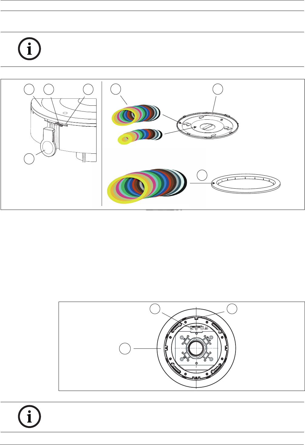
Figure 3.9 Inserting the color rings
1. The detector front panel (1) is secured with a small snap-fit hook (2) on the triple groove
at the side. Insert the supplied opener (3) into the slot above the snap-fit hook (4), fasten
the opener with the thumb and rotate the front panel anti-clockwise.
2. The desired color rings from the supplied set (5) are laid on the front panel (1) and the
detector placed on top. The front panel will only fit in one position.
3. Rotate the front panel clockwise until it engages. The sensor window must remain
unobstructed.
4. Insert the desired color ring into the FAA-500-TR-P Trim Ring (6).
Inserting the detector and trim ring
Figure 3.10 Inserting the detector and trim ring
NOTICE!
Do not switch detector front plates.
The pollution sensor is calibrated individually for each detector and its front plate.
Switching front plates can result in a display of wrong pollution values.
FAA-500-TR-P
51
21 4
3
6
9
8
7
NOTICE!
The FAA-500-RTL Detector Exchanger is recommended for inserting and removing the
detectors.
18 en | Installation Automatic Detectors LSN improved version
F.01U.025.877 | 2.1 | 2011.11 Operation Guide Bosch Sicherheitssysteme GmbH
1. Push the trim ring onto the base until it is heard to engage (7).
2. Remove the protective film from the detector surface.
During initial set-up, the system will detect that a detector does not have a protective
film and signal an O-malfunction.
3. Insert the detector and press it gently upwards. Locking is achieved by a click and lock
mechanism.
The guide grooves ensure the detector can only be inserted into the base in the correct
position.
In the case of very high installation heights: The two easily-visible contact faces (8) are on
the same side as the single guide-groove (9).
Removing the detector and trim ring
1. To remove, push the detector gently upwards in the middle. In this way the locking is
released.
2. To take off the trim ring, carefully lift it up on one side.
3.5 Built-in Housing for Concrete Ceilings
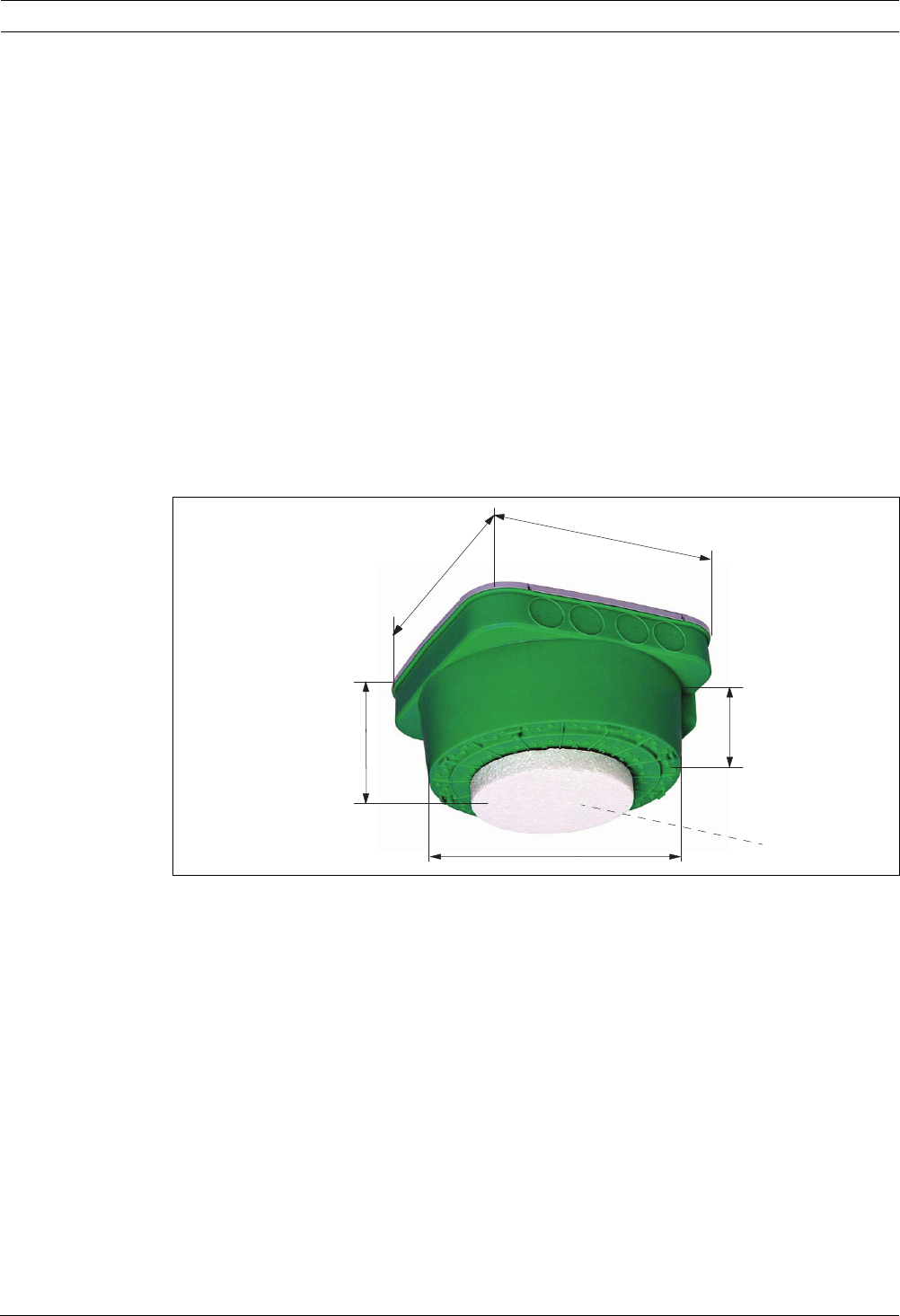
Figure 3.11 FAA-500-CB built-in housing
The FAA-500-CB Built-in Housing is used for the installation of the detector into concrete
ceilings. It allows for easy connection of conduits.
The FAA-500-CB Built-in Housing is placed on the concrete form, fastened and secured against
floating.
Pipe or cable inlets at the FAA-500-CB Built-in Housing within the wall areas are made with an
universal cutting tool. After removing the form-boards, the front part (see Figure 3.11 (1)) is
opened with a fret-saw or hole saw.
Into the hole of the built-in housing, a FAA-500-BB Ceiling Mount Back Box is then inserted
which takes base and detector.
226 mm
226 mm
150 mm
202 mm
75 mm
1
Automatic Detectors LSN improved version Installation | en 19
Bosch Sicherheitssysteme GmbH Operation Guide F.01U.025.877 | 2.1 | 2011.11
3.6 Surface Mount Back Box
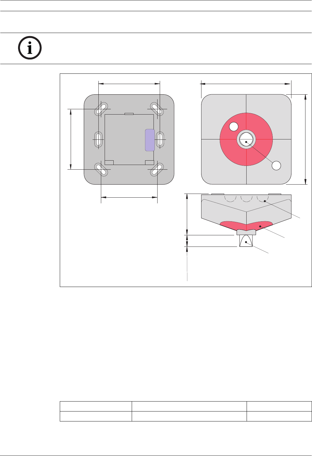
Figure 3.12 FAA-500-SB-H Surface Mount Back Box
The FAA-500-SB-H Surface Mount Back Box allows flush and surface cable duct. The box has a
seal for damp rooms.
For surface cable duct use the side knockouts. For flush cable duct, there are two openings in
the bottom.
Using 13.5 mm cable glands, the maximum cable gauge is 12 mm.
Mounting occurs:
– via the elongated slots or
– via the four mounting holes to mount directly to 4 inch electrical boxes or single gang
switch boxes (for US)
∅
max.:
6--12 mm
13,5 mm13,5 mm
∅
max.:
6--12 mm
120 mm
F.01U.000.654
>PC--FR<
25 mm
∅
40,5 mm
20 mm
14,5 mm
8,5 mm
35 mm
4,1 mm
8,5 mm
20 mm
∅
82 mm
80 mm 2 mm
∅
∅
150 mm
20 en | Installation Automatic Detectors LSN improved version
F.01U.025.877 | 2.1 | 2011.11 Operation Guide Bosch Sicherheitssysteme GmbH
Figure 3.13 Fastening points for mounting
The base is mounted inside the back box via four fastening points.
3.7 External Detector Alarm Displays
If the detector is not directly visible or was mounted in rooms that are inaccessible, an
external detector alarm display is used in the corridors or in the access routes to the
corresponding section of the building or rooms.
The red alarm indication corresponds to DIN 14 623.
3.7.1 Mounting Notes for the Remote Indicator FAA-420-RI
FAA--500/FCA-500 FAA--500--SB-H
NOTICE!
In cases where relay bases are used, no external detector alarm display can be connected.
NOTICE!
If unshielded cables are used, the cable length between an LSN detector and an external
detector alarm display is restricted to a maximum of 3 m.
If shielded cables are used, make sure that the total cable length (= sum of all cables leading
to external detector alarm displays within one loop or stub) does not exceed 500 m.
NOTICE!
The FAA-420-RI must be installed such that the broad side of the red alarm indication (see
Figure 3.14 (2)) follows the observer’s line of sight.
WARNING!
If the maximum current consumption of the connected detector is larger than 20 mA, it can
result in malfunctions and damage to the External Detector Alarm Display.
In order to prevent damage to the device, ensure that the maximum current consumption of
20 mA is not exceeded.
Bosch automatic detectors already have an internal resistance which limits the current
consumption.

Automatic Detectors LSN improved version Installation | en 21
Bosch Sicherheitssysteme GmbH Operation Guide F.01U.025.877 | 2.1 | 2011.11
Figure 3.14 FAA-420-RI dimensions and mounting
1. Before assembly, remove the cap from the base plate: Unlock the snap-fit hook (see
Figure 3.14 (3)) with a flat object (e.g. screwdriver), press in and lift the cap carefully.
2. Mount FAA-420-RI directly on the ceiling or wall. Secure the base plate with two (see
Figure 3.14, (5)) or four (6) screws on an even, dry foundation.
3. For surface-mounted cable insertion, break out the pre-punched cable feeds (see
Figure 3.14 (4)) on any side of the housing. For flush-mounted cable insertion, the cable
is fed in through the opening (see Figure 3.14 (7)) beneath the connection board.
4. Connect FAA-420-RI via two terminals (see Figure 3.15).
Figure 3.15 FAA-420-RI Connection
5. Place the housing on the base place so that the two hooks (see Figure 3.14 (1)) are
inserted into the two slits. Press the cap lightly onto the base plate until the snap-fit
hooks (3) engage.
The technical data can be found in Section 6.4 External Detector Alarm Displays, page 33.
84 mm
84 mm
57 mm
35 mm 57 mm
_
+
+
_
1
2
3
4
5
6
7
Position Description Position Description
1 Hooks 5 Slots for securing the base with
two screws
2 Broad side of the red alarm
indication
6 Slots for securing the base with
four screws
3 Snap-fit hook 7 Cable opening
4 Pre-punched cable feeds
+
_
FAA-420-RI
Cb1/+V
22 en | Installation Automatic Detectors LSN improved version
F.01U.025.877 | 2.1 | 2011.11 Operation Guide Bosch Sicherheitssysteme GmbH
3.7.2 Mounting Notes for the External Detector Alarm Display MPA
Figure 3.16 External detector alarm display MPA, dimensions
Mounts directly on the ceiling or wall.
For surface mounted cable entry, break out the prepared cable entry points (see Figure 3.16.
(3)) on the housing. For flush mounted cable entry, cable entry is through the opening below
the connection board.
Connecting the External Detector Alarm Display MPA
The external detector alarm display is connected using 4 Wago terminals (see Figure 3.17).
– Connecting: insert the stripped cable end (no braided wire) into the terminal.
– Disconnecting: pull out the wire while turning it to and fro.
Up to 4 detectors can be connected to each external detector alarm display.
Three inputs (terminals 2 - 4) allow adjustment to the various line networks.
Making the connection depending on the used line technology
NOTICE!
According to VdS guidelines, the external detector alarm display must be mounted so that the
flat side of the prism (see Figure 3.16 (2)) shows towards the observer's line of sight.
Line technology Fire panels Terminals
GLT BZ 1060 1 + 2
1234
85 mm
39 mm 11 mm
85 mm
1
2
60 mm
55 mm
55 mm
2
1
3
Automatic Detectors LSN improved version Installation | en 23
Bosch Sicherheitssysteme GmbH Operation Guide F.01U.025.877 | 2.1 | 2011.11
Terminal assignment
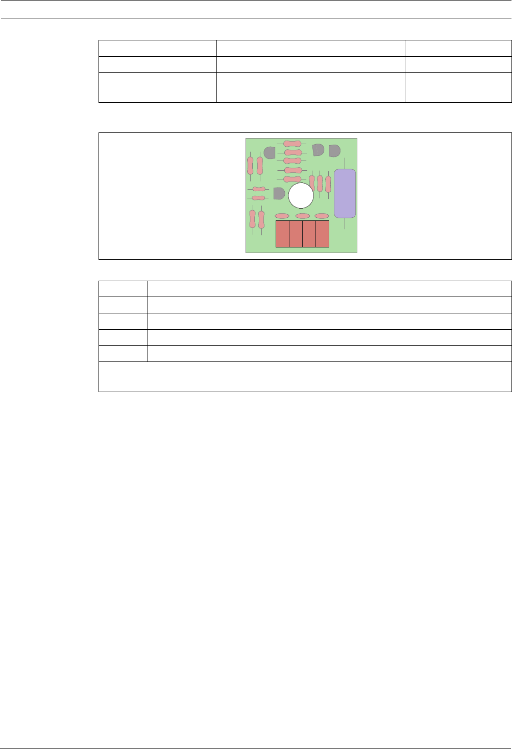
Figure 3.17 Terminal assignment MPA
The technical data can be found in Section 6.4 External Detector Alarm Displays, page 33.
GLT UEZ 1000, UGM 2020, FP 102, 104, 106 1 + 3
LSN BZ 500 LSN, UEZ 1000, UEZ 2000 LSN,
UGM 2020, FPA-5000, FPA 1200
1 + 4
Terminal Assignment
1Ground
2 Flashing input (LED flashes)
3 Static input (LED lights up)
4 Static input (LED lights up)
Only connect to Terminal 4 via a series resistor (integrated in the case of BOSCH detectors);
otherwise, the LED could be destroyed.
Line technology Fire panels Terminals
1234

24 en | Programming Automatic Detectors LSN improved version
F.01U.025.877 | 2.1 | 2011.11 Operation Guide Bosch Sicherheitssysteme GmbH
4 Programming
LSN detectors are programmed according to the required operating mode.
Programming is carried out with the programming software using a PC or laptop connected to
the fire panel.
The suitable response sensitivity of the multisensor detector is programmed by specifying the
operating location (e.g. computer room, office, large kitchen). The selection of the operation
location determines the optimal characteristic diagram for the fire and disturbance variable
evaluation.
If, according to the operating location, a low sensitivity is set for the optical sensor, the alarm
goes off only if the detector senses high levels of smoke and of CO at the same time. This is
the case with open or smouldering fire.
Programming the multisensor detector and linking all detectors by algorithms, considerably
increases the fire detection reliability and lowers the false alarm rate.
In the case of the optical FAP-O 520 detector, the sensitivity of the optical sensors can be set
on three levels. Depending on the operating location, the optical sensor of the detector is
thus adjusted to the environmental conditions. For fire detection, also the time behavior of
the fire characteristics is evaluated. This is very different from the time behavior of the
disturbance variables.
Operating locations for multisensor fire detector
(FAP-OC 520) selectable via the programming
software
Sensitivity
Ounit Cunit
Office (smokers) / waiting room / restaurant /
conference room
low
The sensitivity of
the C unit is always
equally high,
regardless of the
operating location
Conference room / waiting room / exhibition hall low
Warehouse with vehicle traffic low
Production facilities low
Kitchen / casino / restaurant during operation low
Garage low
Office (daily operation) medium
School / kindergarten medium
Theaters / concert halls medium
Office (no traffic) high
Computer room high
High-board warehouse without vehicle traffic with
internal combustion engines
high
Operating location and recommended setting for optical fire
detector (FAP-O 520) selectable via the programming software
Sensitivity O unit
Office (smokers) / waiting room / restaurant / conference room low
Conference room / waiting room / exhibition hall low
Warehouse with vehicle traffic low
Production facilities low
Office (daily operation) medium
School / kindergarten medium
Theaters / concert halls medium

Automatic Detectors LSN improved version Programming | en 25
Bosch Sicherheitssysteme GmbH Operation Guide F.01U.025.877 | 2.1 | 2011.11
Office (no traffic) high
Computer room high
High-board warehouse without vehicle traffic with internal
combustion engines
high
Operating location and recommended setting for optical fire
detector (FAP-O 520) selectable via the programming software
Sensitivity O unit
NOTICE!
For execution of the function test for the FAP-O 520 and FAP-OC 520 detector, the detector
must be switched to test mode. This can be carried out via the fire panel or via the reed
switch at the detector with the help of a magnet (see Section 5 Maintenance and Service,
page 26).

26 en | Maintenance and Service Automatic Detectors LSN improved version
F.01U.025.877 | 2.1 | 2011.11 Operation Guide Bosch Sicherheitssysteme GmbH
5 Maintenance and Service
For maintenance and inspection work on security systems, the regulations laid down in
DIN VDE 0833 strictly apply in Germany; these refer to the maintenance intervals specified by
the manufacturer.
– Maintenance and inspection work should be carried out regularly and by trained
technical personnel.
– Bosch Sicherheitssysteme GmbH recommends a functional and visual inspection at least
once a year.
FAP-OC 520
Due to the life expectancy of the gas sensor, the FAP-OC 520 detector switches off the
C sensors after approx. 5 years of operation. The detector will continue to function as an
Odetector.
At the fire panel, an according fault indication is displayed.
The detector should then be exchanged immediately in order to be able to keep using the
higher reliability of detection of the OC detector.
The detector can be wiped over with a soft cloth and a proprietary plastic cleaning agent.
Cleaning should only take place in test mode.
NOTICE!
The 520 Series Detectors do not require to be removed from their bases for routine
maintenance.
If occasionally a detector requires replacement due to a design change or damage to the
device then this should be carried out by a qualified engineer.
This should only be undertaken when the system is offline and the user has made alternative
arrangements for emergency evacuation.
Test steps Detector type
OOC
Check of the LED display X X
Visual check of the mounting X X
Visual inspection for damage and contamination of the detector surface X X
Check monitoring area for limitations of function and interference
caused by lamps
XX
Test of the optical sensors (see Section 5.4 Inspection Procedure for
FAP-O 520)
X-
Combined test with detector test device and CO testing gas (see
Section 5.3 Inspection Procedure for FAP-OC 520)
-X
NOTICE!
Multisensor detectors with C sensors must be exchanged every 4 - 6 years.
NOTICE!
The cleaning intervals depend on the environmental conditions.

Automatic Detectors LSN improved version Maintenance and Service | en 27
Bosch Sicherheitssysteme GmbH Operation Guide F.01U.025.877 | 2.1 | 2011.11
5.1 Notes for the Service
10-digit serial number: The year of manufacture is coded in the third and fourth digits of the
serial number (example: serial no. 7304900251 - year of manufacture: 2004).
Contamination level: The contamination level is given as a percentage:
Operating hours: Display of the operating time in hours since first putting into operation.
Current measurement values:
Analog smoke value of the scattered light sensor:
CO value: Current measurement value of the CO sensor (only in the case of FAP-OC 520). The
maximum measurement value is 1023.
Error code and cause of malfunction:
The cause of the malfunction is output as a binary code in WinPara:
5.2 General Notes for Detector Testing
The FAP-OC 520 detector has an additional sensor for CO detection in case of fire. The CO
sensor provides improved response behavior and increased stability against nuisance alarms
in critical environmental conditions.
For fire detection, FAP-520 detectors use the time behavior of the fire characteristics, which
differs from the time behavior of disruption variables. Therefore, for a functional test, the
NOTICE!
The serial number, contamination level, operating hours and current analog values can be read
out at all configured detectors (BZ 500 LSN, UEZ 2000 LSN, UGM 2020: via WinPara,
FPA-1200/FPA-5000: via panel display).
Contamination level Fire panel display Required action
Light (> 50 %) LS contam Clean at next service
Moderate (> 75 %) LS dusty Reliability of detection is still guaranteed, clean
as soon as possible
Heavy (100 %) LS malfunction Reliability of detection no longer guaranteed,
fault indication at the fire panel
Detector state Value
New detector, as supplied < 300
Light contamination > 500
Heavy contamination > 600
Malfunction will be triggered > 700
Maximum measurement value 1023
Error code WinPara Cause of malfunction
0000 0001 Malfunction caused by ambient light
0000 0010 Malfunction caused by object in front of detector
0000 0100 Malfunction of detector electronics, O unit
0000 1000 EEPROM read/write error
0001 0000 Temperature outside the range permitted for the CO sensor
0010 0000 Defective CO sensor
0100 0000 General malfunction bit of CO sensor

28 en | Maintenance and Service Automatic Detectors LSN improved version
F.01U.025.877 | 2.1 | 2011.11 Operation Guide Bosch Sicherheitssysteme GmbH
detector must be switched to test mode. Switching to test mode can occur in two ways,
which are described in the alternative test procedures (see below).
5.3 Inspection Procedure for FAP-OC 520
5.3.1 1. Alternative
1. On the central unit, switch the detector zone to be inspected into test mode. This
automatically sets the detector into revision operation and readies it for the detector
test.
Only in revision operation the detector’s individual sensors will trigger with the
corresponding test device. For an alarm, all sensors must trigger at the same time. The
C sensor is triggered using CO test aerosol, the O sensors by being covered up. No
O testing gas is required.
2. Now hold the test device under the detector so that the test beaker is flush with the trim
ring and seals it tightly.
Make sure that the test beaker does not tilt, which could cause the detector to be lifted
up and consequently become detached from its fastening.
3. Spray the CO testing gas for approximately 1 sec.
The test head must remain over the detector until the detector has been triggered.
Distribution of the CO testing gas in the test head and therefore the sensor trigger time
can take up to 20 sec.
4. Both scattered light areas are covered by the test beaker, so that both optical sensors
are also triggered at the same time.
5. The detector triggers the alarm and the red alarm LED flashes.
5.3.2 2. Alternative
The detector can be tested in normal operation if a test device with magnet is used.
Figure 5.1 shows the position of the reed switch (Pos. R) in the case of OC detectors.
If you imagine the CO sensor (Pos. CO) to be in a 12 o’clock position, the reed switch (Pos. R)
is located at approximately 2 o’clock.
NOTICE!
Detectors that are programmed for two-detector dependency must be tested in accordance
with the first alternative (in test mode).
NOTICE!
For the detector test, you need:
– Detector test device for optical fire detector (product ID: 4.998.112.071)
– FAA-500-TTL test adapter with magnet (product ID: F.01U.508.725)
For OC detector, in addition:
– CO testing gas for detector with CO sensor (product ID: 4.998.142.221)
NOTICE!
Make sure that the alarm cannot be passed on to higher-level systems. Programmed
activations of the central unit are retained and are executed.

Automatic Detectors LSN improved version Maintenance and Service | en 29
Bosch Sicherheitssysteme GmbH Operation Guide F.01U.025.877 | 2.1 | 2011.11
Figure 5.1 Position of reed switch
1. Bring the magnet close to the reed switch.
2. The LED of the detector flashes green once a second as soon as the reed switch has been
triggered. The detector will now remain in test mode for 60 sec with automatically set
test parameters (e.g. reduction of the delay time to 15 sec). The green LED flashes for as
long as the detector remains in test mode.
3. Now hold the test device under the detector so that the test beaker is flush with the trim
ring and seal it tightly.
Make sure that the test beaker does not tilt, which could cause the detector to be lifted
up and consequently become detached from its fastening.
4. Proceed as in the case of the first alternative:
– spray with CO gas
– leave the test device on the detector for approx. 20 sec, until the alarm is triggered
5. Both scattered light areas are covered by the test beaker, so that both optical sensors
are triggered as the same time as the CO sensor (no O testing gas is required).
6. The detector triggers the alarm and the red alarm LED flashes.
5.4 Inspection Procedure for FAP-O 520
5.4.1 1. Alternative
1. On the fire panel, switch the detector zone to be inspected to test mode. This
automatically sets the detector into revision operation and readies it for the detector
test.
2. Hold a sufficiently large object (e.g. the detector test device or the detector exchanger)
in both scattered light areas until an alarm is triggered. No O testing gas is required.
5.4.2 2. Alternative
The detector can be tested in normal operation if a test device with magnet is used.
Figure 5.1 shows the position of the reed switch (Pos. R) in O detectors.
CO R
LED
NOTICE!
In the case of programmed intermediate alarm storage, longer trigger times occur.
NOTICE!
Make sure that the alarm cannot be passed on to higher-level systems. Programmed
activations of the central unit are retained and are executed.

30 en | Maintenance and Service Automatic Detectors LSN improved version
F.01U.025.877 | 2.1 | 2011.11 Operation Guide Bosch Sicherheitssysteme GmbH
If you imagine a line through the detector LED to be at the 12 o’clock position, the reed
switch (Pos. R) is located at approximately 2 o’clock.
Figure 5.2 Position of reed switch
1. The LED of the detector flashes green once a second as soon as the reed switch has been
triggered.
The detector will now remain in test readiness for 60 sec with automatically set test
parameters (e.g. reduction of the delay time to 15 sec). The green LED flashes for as long
as the detector remains in test readiness.
2. Now hold the test device under the detector so that the test beaker is flush with the trim
ring. By covering the scattered light areas, both optical sensors are triggered
simultaneously (no O testing gas is required).
3. The detector triggers the alarm and the red alarm LED flashes.
5.5 Repair
In the event of any defect, the entire module/device is exchanged.
5.6 Disposal
Packaging Film of the Fire Detectors with C sensor:
The packaging bag of the multisensor detectors with C sensor consists of tear-resistant
PE-ALU laminated film and may be disposed of with the household garbage.
5.7 Additional Documentation
The current information for each product, as well as the installation instructions supplied with
the device, are available for download as a PDF file via: www.boschsecurity.com\emea\fire.
LED
R
NOTICE!
In the case of programmed intermediate alarm storage, longer trigger times occur.
Unusable electrical and electronic devices/modules must not be disposed of
with normal household refuse. They must be disposed of in compliance with
the applicable regulations and directives (e.g. WEEE in Europe).

Automatic Detectors LSN improved version Technical Data | en 31
Bosch Sicherheitssysteme GmbH Operation Guide F.01U.025.877 | 2.1 | 2011.11
6 Technical Data
6.1 Detector and Trim Ring
Detector type FAP-OC 520 / FAP-OC 520-P FAP-O 520 / FAP-O 520-P
Detection principle Combination of scattered light
and combustion gas
measurement
Scattered light measurement
Special features – Contamination detection
– Drift compensation in
optical and in gas
measuring unit
– Contamination detection
– Drift compensation in
optical unit
Address allocation Manual or automatic address setting via rotary switches
Operating voltage 15 to 33 V DC
Current consumption 3.25 mA
Individual display Two-color LED: red/green
Alarm output By data word via two-wire signal line
Indicator output Open collector, switches 0 V over 1.5 kΩ, max. 15 mA
Response sensitivity:
– O unit < 0.36 dB/m (EN 54-7) < 0.18 dB/m (EN 54-7)
– Gas unit in ppm-range -
Max. monitoring area 120 m2 (note local guidelines)
Maximum installation
height
16 m (note local guidelines)
Minimum installation
height
Out of arm’s reach
Minimum distance to
lamps
50 cm
Permitted air speed 20 m/s
Permitted operating
temperature
-10 °C to +50 °C -20 °C to +65 °C
Permitted relative
humidity
<95 % (non-condensing)
Protection class as per
IEC 60529
IP 33 IP 53
Dimensions:
– Detector without trim
ring
Ø 113 mm x 55 mm (without base)/Ø 113 x 70 mm (with base)
– Detector with trim
ring
Ø 150 mm x 55 mm (without base)/Ø 150 x 70 mm (with base)
Housing material Polycarbonate
Color of detector housing Signal white (RAL 9003)
Color of detector front
panel:
– White variant Signal white, matt

32 en | Technical Data Automatic Detectors LSN improved version
F.01U.025.877 | 2.1 | 2011.11 Operation Guide Bosch Sicherheitssysteme GmbH
6.2 Detector Base
6.3 Mounting Boxes
– Transparent variant
(-P)
Transparent/silver gray, (RAL 7001)
Weight
(without/with pack.):
– Detector Approx. 180 g/370 g Approx. 170 g/360 g
– Trim ring
FAA-500-TR(-P)
Approx. 30 g/60 g
Detector type FAP-OC 520 / FAP-OC 520-P FAP-O 520 / FAP-O 520-P
Base type FAA-500 FAA-500-R (with relay)
Special note - For connection to FPA-5000
only
Connections Screw terminals for:
– Power supply (0V, +V)
–LSN
(a-in/out, b-in, b-out)
–C-point
– Shielding
Screw terminals for:
– Power supply (0V, +V)
–LSN
(a-in/out, b-in, b-out)
–C-point
–Shielding
– Relay (NO, NC, COM)
Current consumption - 0.2 mA
Load capacity of relay contact - 1 A, 30 V DC
Cable cross section 0.3 mm2 - 3.3 mm2 (22 AWG - 12 AWG)
Material and color Polycarbonate, signal white (RAL 9003)
Dimensions (Ø x H) 145.6 x 63.5 mm
Weight (without/with pack.) Approx. 200 g/280 g Approx. 210 g/290 g
FAA-500-BB Ceiling Mount Back Box
Mounting dimensions:
– Thickness of the false ceiling Max. 32 mm
– Required bored hole Ø 130 mm (tolerance -1 mm to +5 mm)
– Installation height 11 cm
Max. cable diameter 1.4 cm
Material and color Polypropylene/white
Dimensions (Ø x H) 140 x 104 mm
Weight (without/with pack.) Approx. 100 g/200 g
FAA-500-CB Built-in Housing for concrete ceilings
Material and color Plastic/polystyrene
Gray/green
Dimensions (Ø x H) 226 x 226 x 150 mm
Weight Approx. 345 g

Automatic Detectors LSN improved version Technical Data | en 33
Bosch Sicherheitssysteme GmbH Operation Guide F.01U.025.877 | 2.1 | 2011.11
6.4 External Detector Alarm Displays
FAA-500-SB-H Surface Mount Back Box with damp room seal
Housing (back box/seal):
– Material Polycarbonate (PC-FR)/TPE
– Color White/transparent
Cable entries
– 2 x Ø 20 mm (pre-punched) for cable gland
13.5 mm
– 2 x Ø 25 mm (pre-punched)
Dimensions (Ø x H) 150 x 82 mm
Weight Approx. 225 g
FAA-420-RI
Operating voltage 5 to 30 V DC
Maximum current consumption 20 mA
Display medium 2 LEDs
Permissible wire gauge 0.6 to 2 mm
Dimensions 84 x 84 x 35 mm
Weight 45 g
Protection class as per IEC 60529 IP 40
MPA
Operating voltage 9 V DC to 30 V DC
Current consumption for
display
Terminal 2 Approx. 2 mA
Terminal 3 Limited to approximately 13 mA
Terminal 4 Limit to 20 mA maximum*
Display medium 1 LED via a light guide
Permissible wire gauge 0.6 to 0.8 mm
Dimensions 85 x 85 x 50 mm
Weight 65 g
Protection class as per IEC 60529 IP 40
* Non-observance may cause malfunction and damage the LED. In case of BOSCH detectors,
limitation occurs via internal resistor.

34 en | Automatic Detectors LSN improved version
F.01U.025.877 | 2.1 | 2011.11 Operation Guide Bosch Sicherheitssysteme GmbH
A Appendix
A.1 Abbreviations
A.2 Order Overview
A.2.1 Detector and Trim Ring
a.P. auf Putz (surface-mounted)
ABS AcrylonitrileButadieneStyrene
DIBt Deutsches Institut für Bautechnik (German Institute for Building Technology)
DIN Deutsches Institut für Normung e.V. (German Institute for Standardization)
EN Europäische Norm (European standard)
FAA Fire Analog Accessory
FACP Fire Alarm Control Panel
FAP Fire Analog Photoelectric
FCA Fire Conventional Accessory
FCP Fire Conventional Photoelectric
GLT Gleichstromlinientechnik (conventional technology)
LED Light Emitting Diode
LSN Lokal SecurityNetwork
NVU Netz-Verarbeitungsumsetzer (network processing converter)
O Optical (smoke)
OC Optical (smoke), chemical (gas)
PC Polycarbonate
PI Product information
PP Polypropylene
u.P. unter Putz (flush-mounted)
UEZ Universelle Europazentrale (universal European fire panel)
UGM Universelle Gefahrenmeldezentrale (danger detection system)
VDE Verband Deutscher Elektrotechniker e.V.
(Association of German Electrical Engineers)
VdS VdS Schadenverhütung GmbH (company name)
Description Product ID
FAP-O 520 Optical Fire Detector LSN improved, white F.01U.510.149
FAP-OC 520 Multisensor Fire Detector LSN improved, optical/chemical,
white
F.01U.510.151
FAP-O 520-P Optical Fire Detector LSN improved, transparent with color
toning inserts
F.01U.510.161
FAP-OC 520-P Multisensor Fire Detector LSN improved, optical/chemical,
transparent with color toning inserts
F.01U.510.162
Automatic Detectors LSN improved version | en 35
Bosch Sicherheitssysteme GmbH Operation Guide F.01U.025.877 | 2.1 | 2011.11
A.2.2 Detector Bases/Accessories
A.2.3 Mounting Boxes
A.2.4 Service/Hardware Accessories
FAA-500-TR-W Trim Ring, White, for the detectors FAP-O 520 and
FAP-OC 520
4.998.151.295
FAA-500-TR-P Trim Ring, Transparent, with color toning inserts for
FAP-O 520-P and FAP-OC 520-P detectors
4.998.151.296
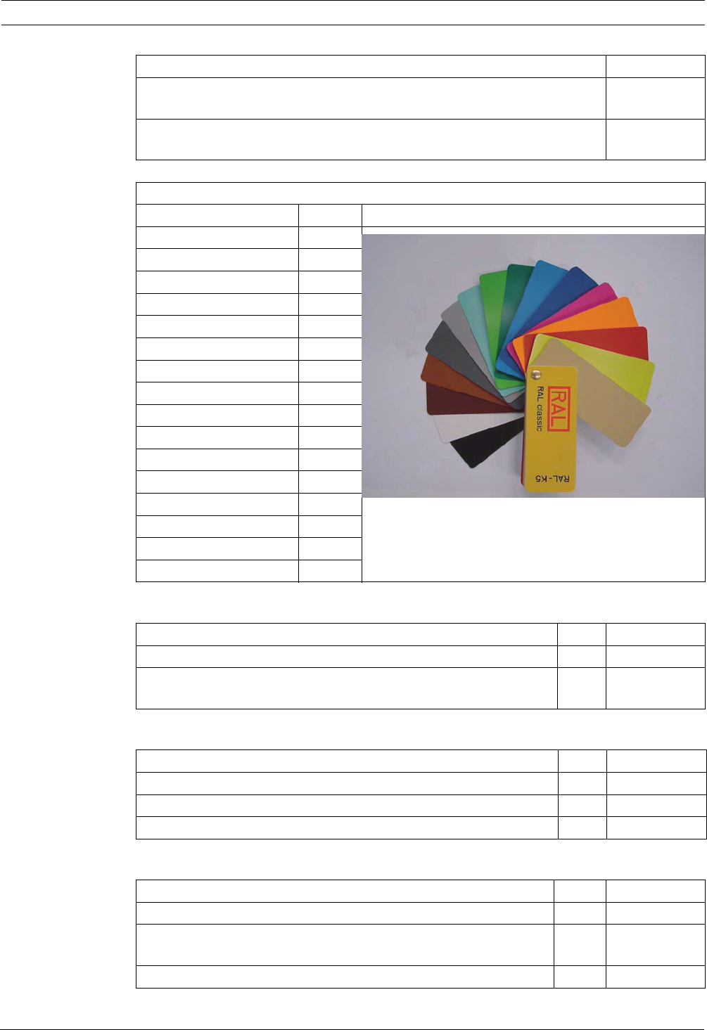
Color toning inserts for FAP-O 520-P, FAP-OC 520-P and FAA-500-TR-P:
Color RAL
beige 1001
sulfur yellow 1016
red orange 2001
fluorescent orange 2007
erica violet 4003
signal blue 5005
sky blue 5015
turquoise green 6016
yellow green 6018
light green 6027
signal gray 7004
basalt gray 7012
earth brown 8003
nut brown 8011
signal white 9003
graphite black 9011
Description Product ID
1001
1016
2001
2007
4003
5005
5015
6016
6018
6027
7004
7012
8003
8011
9003
9011
Description DU* Product ID
FAA-500 LSN Detector Base PE 4.998.151.297
FAA-500-R LSN Detector Base with relay (for connection to
FPA-5000 only)
PE 4.998.151.299
Description DU* Product ID
FAA-500-BB Ceiling Mount Back Box PE 4.998.151.302
FAA-500-CB Built-in Housing for concrete ceilings PE F.01U.508.713
FAA-500-SB-H Surface Mount Back Box with damp room seal PE F.01U.510.166
Description DU* Product ID
FAA-500-RTL Detector Exchanger for 500 and 520 Series Detectors PE F.01U.508.720
FAA-500-TTL Test Adapter with Magnet for 500 and 520 Series
Detectors
PE F.01U.508.725
Test Device for Optical Fire Detectors PE 4.998.112.071

36 en | Automatic Detectors LSN improved version
F.01U.025.877 | 2.1 | 2011.11 Operation Guide Bosch Sicherheitssysteme GmbH
* DU = delivery unit, PE = pieces, PU = packaging unit
CO Testing Gas (spray can)
for detectors with CO sensors (1 PU = 12 pieces)
for use in test device for optical fire detectors
PU 4.998.142.221
Telescopic Pole (1 m to 3.38 m) made of fiberglass, can be
extended with max. 3 extension poles
PE 4.998.112.069
Extension Pole made of fiberglass (1 m) PE 4.998.112.070
Transport Bag for test devices and accessories PE 4.998.112.073
MPA External Detector Alarm Display according to DIN 14 623 (with
VdS approval)
PE 2.799.330.669
FAA-420-RI Remote Indicator according to DIN 14 623 PE F.01U.522.590
Description DU* Product ID

Bosch Sicherheitssysteme GmbH
Robert-Bosch-Ring 5
85630 Grasbrunn
Germany
www.boschsecurity.com
© Bosch Sicherheitssysteme GmbH, 2011
