Bosch System_Information_11.3_EN En Us FPA 5000 Installation Manual 1218442507
User Manual: Bosch en-us Panel Controller
Open the PDF directly: View PDF ![]() .
.
Page Count: 170 [warning: Documents this large are best viewed by clicking the View PDF Link!]
- Table of contents
- 1 System Information
- 2 Product Description
- 3 Planning
- 4 Installation
- 4.1 General Information
- 4.2 Quick Installation Guide
- 4.3 Installation of Housing Components
- 4.4 Accessories for Housing
- 4.5 Power Supply Brackets
- 4.6 UPS 2416 A Universal Power Supply 24 V/6 A
- 4.7 Panel Rails
- 4.8 MPC Panel Controller
- 4.9 Functional Modules
- 4.9.1 Installation and Removal
- 4.9.2 ANI 0016 A Annunciator Module
- 4.9.3 BCM‑0000‑B Battery Controller Module
- 4.9.4 CZM 0004 A 4 Zone Conventional Module
- 4.9.5 ENO 0000 B Fire Service Interface Module
- 4.9.6 FPE‑5000‑UGM Interface Module
- 4.9.7 IOP 0008 A Input/Output Module
- 4.9.8 IOS 0020 A 20 mA Communication Module
- 4.9.9 IOS 0232 A RS232 Communication Module
- 4.9.10 LSN 0300 A LSN improved Module 300 mA
- 4.9.11 LSN 1500 A LSN improved Module 1500 mA
- 4.9.12 NZM 0002 A Notification Appliance Zone Module
- 4.9.13 RMH 0002 A Relay Module for Mains Voltage
- 4.9.14 RML 0008 A Relay Module for Low Voltage
- 4.9.15 Accessories for Functional Modules
- 4.10 Cable Sets
- 4.11 Monitoring auxiliary power according to EN 54-13
- 4.12 FPP‑5000 External Power Supply Unit Kit 24 V/6 A
- 4.13 THP 2020 A Thermal Printer
- 4.14 Remote Keypad
- 5 Commissioning
- 6 Maintenance and Service
- 7 Technical Data
- 7.1 System Limits
- 7.2 Power loss of FPA-5000 Components
- 7.3 Housing and Accessories
- 7.3.1 Housings for Frame Installation
- 7.3.2 Housings for Wall Mounting
- 7.3.3 PRS-0002-C Panel Rail Short for 2 Modules
- 7.3.4 PRS 0002 A Panel Rail Short for 2 Modules (no longer available)
- 7.3.5 PRD 0004 A Panel Rail Long for 4 Modules
- 7.3.6 FPO‑5000‑PSB1/FPO‑5000‑PSB‑CH Power Supply Brackets
- 7.3.7 UPS 2416 A Universal Power Supply 24 V/6 A
- 7.4 Panel Controller and Remote Keypad
- 7.5 Functional Modules
- 7.5.1 ANI 0016 A Annunciator Module
- 7.5.2 BCM‑0000‑B Battery Controller Module
- 7.5.3 CZM 0004 A 4 Zone Conventional Module
- 7.5.4 ENO 0000 B Fire Service Interface Module
- 7.5.5 FPE‑5000‑UGM Interface Module
- 7.5.6 IOP 0008 A Input/Output Module
- 7.5.7 IOS 0020 A 20 mA Communication Module
- 7.5.8 IOS 0232 A RS232 Communication Module
- 7.5.9 LSN 0300 A LSN improved Module 300 mA
- 7.5.10 LSN 1500 A LSN improved Module 1500 mA
- 7.5.11 NZM 0002 A Notification Appliance Zone Module
- 7.5.12 RMH 0002 A Relay Module for mains voltage
- 7.5.13 RML 0008 A Relay Module for Low Voltage
- 7.6 FPP‑5000 External Power Supply Unit Kit 24 V/6 A
- 8 Appendix
- 8.1 Options with requirements under EN 54‑2:1997/A1:2006
- 8.2 Component Overview
- 8.2.1 Frame Installation Housings, Mounting Frames and Installation Kits
- 8.2.2 Wall Mounting Housings and Installation Kits
- 8.2.3 Accessories for Housing
- 8.2.4 Panel Rails
- 8.2.5 Power Supply Units, Power Supply Brackets, Batteries
- 8.2.6 Panel Controller/Remote Keypad
- 8.2.7 Functional Modules
- 8.2.8 Cable Sets
- 8.2.9 Thermal Printer
- 8.2.10 CAN/FOC Adapters
- 8.3 Special Applications
- Index
Modular Fire Panel
FPA-5000
en System Information

Modular Fire Panel Table of contents | en 3
Bosch Sicherheitssysteme GmbH System Information 09.2017 | 11.3 | F.01U.028.089
Table of contents
1System Information 6
2Product Description 6
2.1 FPA-5000 with Functional Modules 6
2.2 MPC Panel Controller 11
2.3 Remote Keypad 12
2.4 Housings for Frame Installation 13
2.5 Housings for Wall Mounting 16
2.6 System Overview of FPA-5000 with Peripherals 18
2.7 Networking 23
2.8 Connection to BIS 23
2.9 Connecting a Voice Alarm System 24
3Planning 24
3.1 General Information 24
3.2 Structures in Local Security Network 25
3.3 Detection Points 27
3.4 Addressing 27
3.5 Achievable Cable Length with LSN 0300 A 28
3.6 Achievable Cable Length with LSN 1500 A 31
3.7 Examples of Housing Equipment 35
3.8 Configuration of BCM Battery Controller Module 36
3.9 Redundancy 40
4Installation 42
4.1 General Information 42
4.2 Quick Installation Guide 43
4.3 Installation of Housing Components 44
4.3.1 Installation Instructions for Housing 45
4.3.2 Installation Dimensions for Wall Mounting Housing 47
4.3.3 Installation Dimensions for Frame Installation Housing 53
4.3.4 Installation Dimensions for Mounting Frames 56
4.3.5 Installation Kits for 48 cm (19”) Racks 59
4.4 Accessories for Housing 61
4.4.1 RLE 0000 A Junction Board 61
4.4.2 HMP 0003 A Mounting Plate for Mounting Frame 63
4.4.3 FPO-5000-EB Earth Bar 65
4.5 Power Supply Brackets 65
4.5.1 FPO‑5000‑PSB‑CH Power Supply Bracket 67
4.5.2 FPO-5000-PSB1 Power Supply Bracket 71
4.6 UPS 2416 A Universal Power Supply 24 V/6 A 72
4.7 Panel Rails 78
4.7.1 PRS-0002-C Panel Rail Short for 2 Modules 78
4.7.2 PRD 0004 A Panel Rail Long for 4 Modules 80
4.7.3 Panel Rail Installation 81
4.8 MPC Panel Controller 84
4.9 Functional Modules 99
4.9.1 Installation and Removal 100
4.9.2 ANI 0016 A Annunciator Module 101
4.9.3 BCM‑0000‑B Battery Controller Module 101
4.9.4 CZM 0004 A 4 Zone Conventional Module 107

4en | Table of contents Modular Fire Panel
09.2017 | 11.3 | F.01U.028.089 System Information Bosch Sicherheitssysteme GmbH
4.9.5 ENO 0000 B Fire Service Interface Module 107
4.9.6 FPE‑5000‑UGM Interface Module 109
4.9.7 IOP 0008 A Input/Output Module 110
4.9.8 IOS 0020 A 20 mA Communication Module 111
4.9.9 IOS 0232 A RS232 Communication Module 112
4.9.10 LSN 0300 A LSN improved Module 300 mA 113
4.9.11 LSN 1500 A LSN improved Module 1500 mA 114
4.9.12 NZM 0002 A Notification Appliance Zone Module 116
4.9.13 RMH 0002 A Relay Module for Mains Voltage 117
4.9.14 RML 0008 A Relay Module for Low Voltage 118
4.9.15 Accessories for Functional Modules 119
4.10 Cable Sets 120
4.11 Monitoring auxiliary power according to EN 54-13 121
4.12 FPP‑5000 External Power Supply Unit Kit 24 V/6 A 121
4.13 THP 2020 A Thermal Printer 123
4.14 Remote Keypad 127
5Commissioning 141
5.1 Notes 141
5.2 Documentation 141
5.3 Quick Guide for Commissioning 141
5.4 Functional Test 141
5.4.1 Preparation 141
5.4.2 Testing the Power Supply 142
5.4.3 Testing the Conventional and LSN Functions 142
5.4.4 Testing the Addressing/Activation 142
6Maintenance and Service 143
6.1 Warranty 143
6.2 Repair 143
6.3 Disposal 143
6.4 Additional Documentation 143
7Technical Data 143
7.1 System Limits 143
7.2 Power loss of FPA-5000 Components 145
7.3 Housing and Accessories 146
7.3.1 Housings for Frame Installation 146
7.3.2 Housings for Wall Mounting 146
7.3.3 PRS-0002-C Panel Rail Short for 2 Modules 146
7.3.4 PRS 0002 A Panel Rail Short for 2 Modules (no longer available) 147
7.3.5 PRD 0004 A Panel Rail Long for 4 Modules 147
7.3.6 FPO‑5000‑PSB1/FPO‑5000‑PSB‑CH Power Supply Brackets 148
7.3.7 UPS 2416 A Universal Power Supply 24 V/6 A 148
7.4 Panel Controller and Remote Keypad 148
7.4.1 MPC 148
7.4.2 Remote Keypad 149
7.4.3 FSP-5000-RPS Programming Software 150
7.5 Functional Modules 150
7.5.1 ANI 0016 A Annunciator Module 150
7.5.2 BCM‑0000‑B Battery Controller Module 150
7.5.3 CZM 0004 A 4 Zone Conventional Module 151

Modular Fire Panel Table of contents | en 5
Bosch Sicherheitssysteme GmbH System Information 09.2017 | 11.3 | F.01U.028.089
7.5.4 ENO 0000 B Fire Service Interface Module 152
7.5.5 FPE‑5000‑UGM Interface Module 152
7.5.6 IOP 0008 A Input/Output Module 152
7.5.7 IOS 0020 A 20 mA Communication Module 153
7.5.8 IOS 0232 A RS232 Communication Module 153
7.5.9 LSN 0300 A LSN improved Module 300 mA 153
7.5.10 LSN 1500 A LSN improved Module 1500 mA 154
7.5.11 NZM 0002 A Notification Appliance Zone Module 155
7.5.12 RMH 0002 A Relay Module for mains voltage 155
7.5.13 RML 0008 A Relay Module for Low Voltage 156
7.6 FPP‑5000 External Power Supply Unit Kit 24 V/6 A 156
7.6.1 FPP‑5000 Kit 156
7.6.2 FPP‑5000‑TI Trouble Interface 157
7.6.3 FPP‑5000‑TI13 Communication Interface 157
8Appendix 157
8.1 Options with requirements under EN 54‑2:1997/A1:2006 157
8.2 Component Overview 158
8.2.1 Frame Installation Housings, Mounting Frames and Installation Kits 158
8.2.2 Wall Mounting Housings and Installation Kits 158
8.2.3 Accessories for Housing 159
8.2.4 Panel Rails 159
8.2.5 Power Supply Units, Power Supply Brackets, Batteries 159
8.2.6 Panel Controller/Remote Keypad 160
8.2.7 Functional Modules 162
8.2.8 Cable Sets 162
8.2.9 Thermal Printer 162
8.2.10 CAN/FOC Adapters 163
8.3 Special Applications 164
8.3.1 Controlling Extinguishing Systems 164
Index 165
6en | System Information Modular Fire Panel
09.2017 | 11.3 | F.01U.028.089 System Information Bosch Sicherheitssysteme GmbH
1 System Information
Safety Instructions
Danger!
The fire panel contains live components.
Touching live components can result in electric shock.
Disconnect the power supply to the fire panel before all maintenance or installation work.
Notice!
The fire panel may only be installed and commissioned by trained specialist personnel.
Notice!
Have maintenance and inspection work carried out regularly by trained, qualified personnel.
Bosch Sicherheitssysteme GmbH recommends a functional and visual inspection at least once
a year.
Notice!
The fire panel is designed for indoor installation.
After installing batteries, the poles must be masked. Appropriate masking strips are included
with the housing in which the batteries are installed.
Use fuses complying with national regulations to protect the power lines.
Notice!
Do not dispose of batteries with domestic waste. Use the collection points provided locally.
See http://www.boschsecurity.com/standards for further information.
Notice!
Consider national and local regulations when installling and operating the fire system.
2 Product Description
With its modular design, the FPA-5000 Fire Panel is easily adapted to local circumstances and
regulations. Due to the different functional modules, country-specific characteristics are
accommodated in the connection just as quickly as the respective alarm protocol.
2.1 FPA-5000 with Functional Modules
The fire panel is available with two different housings:
– Housing for mounting directly on the wall
– Frame installation housings, which are fitted to the mounting frame and can be swiveled.
Special installation kits also allow installation in 482.6mm (19") racks. All housings can be
extended with various additional housings.
The fire panel is configured on a laptop using the FSP-5000-RPS programming software.
Modular Fire Panel Product Description | en 7
Bosch Sicherheitssysteme GmbH System Information 09.2017 | 11.3 | F.01U.028.089
The MPC Panel Controller is the central component of the system. All messages are shown on
the display. The complete system is operated via a touch screen. The user-friendly interface
adapts to the relevant situation. This allows correct operation that is both simple and clear
and targeted and intuitive. The FSP-5000-RPS programming software enables adaptation to
country-specific circumstances.
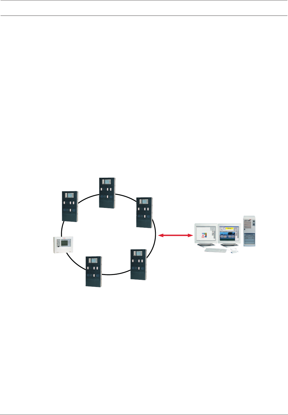
The panels can be networked with one another and with the remote keypad using the external
CAN bus interface. With a loop or bus structure, this networking is adapted to the conditions
of use (see Networking, page 23).
The FPA-5000 can be connected to the Bosch UGM Universal Security System and thus
integrated into large-scale systems.
Connection to a building management system (Bosch Building Integration System BIS) is
possible via an Ethernet interface using an OPC server (see Connection to BIS, page 23). The
FSM-5000-FSI Software Interface Package allows custom connections to other management
systems.
The FPA-5000 can be connected to a Plena Voice Alarm System. The Praesideo/PAVIRO
systems can be connected using an IP based interface module. See Connecting a Voice Alarm
System, page 24.
The FMR-5000-C Remote Keypad allows decentralized operation of the panel or the panel
network.
Ethernet
BIS
OPC
FPA-5000
FMR-5000
Figure2.1: FPA-5000 Fire Panel (with FMR-5000-C Remote Keypad) in a network
System Overview
The figure below shows an example configuration:
8en | Product Description Modular Fire Panel
09.2017 | 11.3 | F.01U.028.089 System Information Bosch Sicherheitssysteme GmbH
N
I
TUO
N
I
TUO
#
0
*
8 9
5 6
2 3
7
4
1
?
PQRS TUV WXYZ
GHI JKI MNO
ABC DEF
F i r e
Test
City Tie
City Tie Fa ult
Ground F ault
Battery F ault
Power
Trouble
Signal S ilence
Bypass ed
Superv isory
N A C 1 N A C 3N A C 7N A C
9
N A C 5
N A C 2N A C 4N A C 8N A C
10
N A C 6
PS 2PS 3 PS 5P S
6
PS 4
BC B AT
BC B AT
BA T 2
10 A
25 A
25 A
Bridge 2-3 Bridge 3-4 Bri dge 4- 5 Bridge 5- 6
- - - --+ + + ++
- + - +
-
+
BA T 1 AB AT 1 B
-
+-
+
NETZEIN
NETZSTROM
Störung
BATTERIE1
Störung
BATTERIE2
Störung
FAULT
MAIN
+ - BAT1
+ - BAT2
+ - BAT1
+ - +-
FAULT AC
FAULT
AUX3
+ - AUX4
+ -
AUX2
+ -
AUX1
+ - AUX5
+ - AUX6
+ -
BCM0000A
L SN 0 3 0 0 A
AU X 1
+ - L S N 1
a -b +AU X 2
+ - L S N 2
a -b +
ZONE4
Störung
ZONE3
Störung
ZONE2
Störung
ZONE1
Störung
CZM0004A
AUX1
+ - OUT1
+- IN1
+- AUX2
+ - OUT2
+- IN2
+-
AUX3
+ - OUT3
+- IN3
+- AUX4
+ - OUT4
+- IN4
+-
ANI0016A
F2F1
NC1
NO1
C1
NC2
NO2
C2
FB1
+-FB2
+ -
RELAIS2
Störung
RELAIS1
Störung
RMH0002A
OUT3
OUT2
OUT4
OUT6
OUT5
OUT7
GND
OUT8
GND
GND
GND
IN1
IN3
IN2
IN4
IN6
IN5
IN7
GND
IN8
GND
GND
GND
OUT1
IOP0008A
3
4
2
5
1
6
7
9
110
11
8
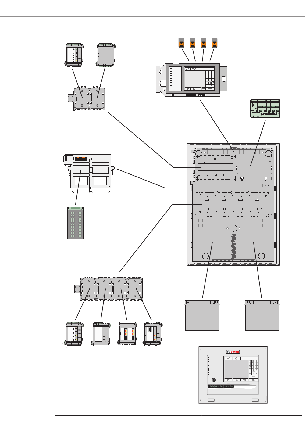
Figure2.2: Example configuration
Position Description Position Description
1 Functional modules 7 Power supply unit

Modular Fire Panel Product Description | en 9
Bosch Sicherheitssysteme GmbH System Information 09.2017 | 11.3 | F.01U.028.089
Position Description Position Description
2 Address cards 8 Housing (in this case: HCP0006A)
3 Panel controller 9 Panel rail, long
4 Distributor, optional (RLE) 10 Batteries
5 Panel rail, short 11 Remote keypad
6 Power supply bracket
Functions
Due to its modular structure, the FPA‑5000 Modular Fire Panel provides complete flexibility
and thus customized solutions for any application.
The configuration of the components is supported by Planning Software by Bosch for fire
alarm systems. The software provides information about the size and number of housings, the
modules and the energy balance calculation.
Depending on specific requirements, the planning involves choosing from the following
options:
–Housing type (frame and wall mounting)
– Selection of a basic housing
– Extension housing, optional
– Power supply housing, optional
– Installation kits (optional) for installation in 482.6mm (19") racks
–Panel controller
– Selection from a range of language versions
–Panel rail
– Selection according to housing type and/or number of functional modules required
–Power supply
– Batteries
– Power supply units for additional power supply
– Power supply brackets
The power supply brackets on frame installation housings are preinstalled ex works;
for wall-mounted housings, power supply brackets can be selected as required.
–Thermal printer
– THP2020A Thermal Printer
The thermal printer is used to document operating procedures on the panel, as well
as alarm and fault messages (see THP2020A Thermal Printer, page 123). Plain text
can also be printed. Programming is carried out via the programming software
FSP-5000-RPS.
–Additional accessories
– Front doors
– Cable sets for special applications (see Cable Sets, page 120)
–Functional modules
Functional modules are independent, encapsulated units that can be inserted into any
slot on the panel. The power supply and the data traffic with the panel are therefore
provided automatically. The module is identified by the panel with no further settings and
operates in the default operating mode (plug and play).
Wiring to external components is performed using compact connector/screw terminals.
After a replacement, only the connectors need to be reinserted; there is no need for
extensive rewiring.

10 en | Product Description Modular Fire Panel
09.2017 | 11.3 | F.01U.028.089 System Information Bosch Sicherheitssysteme GmbH
Module Description Function
ANI 0016 A Annunciator Module Indicating system statuses; with 16 red and 16
yellow freely programmable LEDs
BCM-0000-B Battery Controller
Module
Monitoring the power supply to the panel and the
battery charge level
CZM 0004 A 4 Zone Conventional
Module
Connecting existing conventional peripherals using
four monitored conventional lines
ENO 0000 B Fire Service
Interface Module
Connecting fire service equipment complying with
DIN 14675
FPE-5000-UGM Interface Module Connection to UGM systems
IOP 0008 A Input/Output OC
Module
Individual displays or flexible connection of various
electrical devices, with 8 independent digital inputs
and 8 open collector outputs
IOS 0020 A 20mA
Communication
Module
With S20, RS232 and S1 interfaces
IOS 0232 A RS232
Communication
Module
Connection of two devices using two independent
serial interfaces, e.g. a Plena Voice Alarm System,
laptop or printer.
LSN 0300 A LSN improved
Module 300mA
Connection of an LSN loop with up to 254LSN
improved elements or 127LSN classic elements at a
maximum line current of 300mA
LSN 1500 A LSN improved
Module 1500mA
Connection of an LSN loop with up to 254LSN
improved elements at a maximum line current of
1500mA or 127LSN classic elements at a maximum
line current of 300mA
NZM 0002 A Notification
Appliance Zone
Module
Allows connection of two conventional, monitored
notification appliance circuit lines
RMH 0002 A Relay Module Monitored connection of external elements with
feedback, with two changeover contact relays
suitable for switching mains voltage
RML 0008 A Relay Module For low voltage switching, with eight changeover
contact relays
Further information can be found in Functional Modules, page 99.
The technical data can be found in Housing and Accessories, page 146.
Notice!
Planning Software by Bosch can be used to plan fire alarm systems that conform to the
relevant limits (e.g. in terms of cable length and power supply).
Modular Fire Panel Product Description | en 11
Bosch Sicherheitssysteme GmbH System Information 09.2017 | 11.3 | F.01U.028.089
Notice!
Planning Software by Bosch for fire alarm systems enables the system dimensions, the energy
requirements and the quantity and prices of the elements required to be estimated at each
different phase in the planning process.
The software is designed for planners and engineering offices that want to produce a
quotation for a fire alarm system.
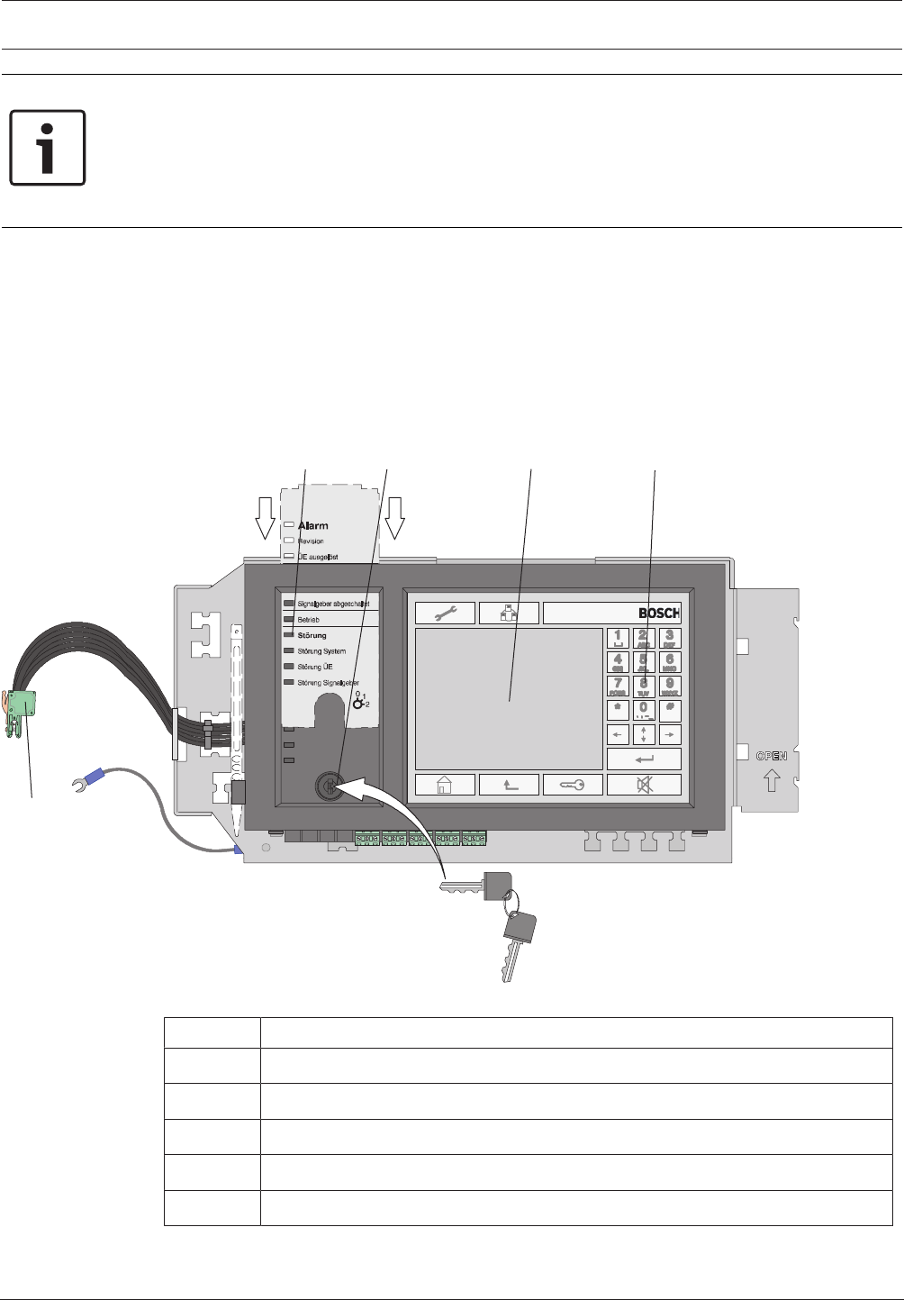
2.2 MPC Panel Controller
The panel controller is the central component of the fire detection system. All messages are
shown on the display. The entire system is operated via a touch screen. The user-friendly user
interface adapts to the various situations. This allows correct operation that is both simple
and clear and targeted and intuitive.
The FSP-5000-RPS programming software enables adaptation to country-specific
circumstances.
1234
5
Figure2.3: Overview of MPC system
Position Description
1 LEDs for displaying the operating status, with labeling strips
2 Key switch
3 Touch screen
4 Membrane keys
5 CAN bus, internal

12 en | Product Description Modular Fire Panel
09.2017 | 11.3 | F.01U.028.089 System Information Bosch Sicherheitssysteme GmbH
Networking
Up to 32panel controllers, remote keypads and OPC servers can be combined to form a
network.
Alarm Indication
The display element is an LCD touch screen with automatically activated backlighting. 12LEDs
provide continuous information about the operating status of the panel or system. Additional
LED indicator modules each with 16detection points can be used to provide visual indication
of alarms or faults.
Operation and Processing of Messages
The panel is operated and all messages are processed on the functionally designed operating
panel with the integrated LCD touch screen. There are permanent keys on the right, at the
bottom, and along the top of the display as well as variable virtual keys located in the touch
screen area.
The language for the menu navigation can be selected as required.
Below the status LEDs is a key switch with two programmable positions, e.g.:
– for switching between day/night mode, or
– for switching local alarm on/off (internal/external alarm)
Interfaces
A USB interface is provided to quickly transfer the required configuration to the panel
controller. There is also an Ethernet interface for adding the BIS software to the local network,
for example.
Saving and Printing Messages
All incoming messages and events are saved internally and can be viewed on the display at any
time. A log printer for printing incoming messages can be connected.
Installation
Information on installing the panel controller can be found in MPCPanel Controller, page 84.
The technical data can be found in MPC, page 148.
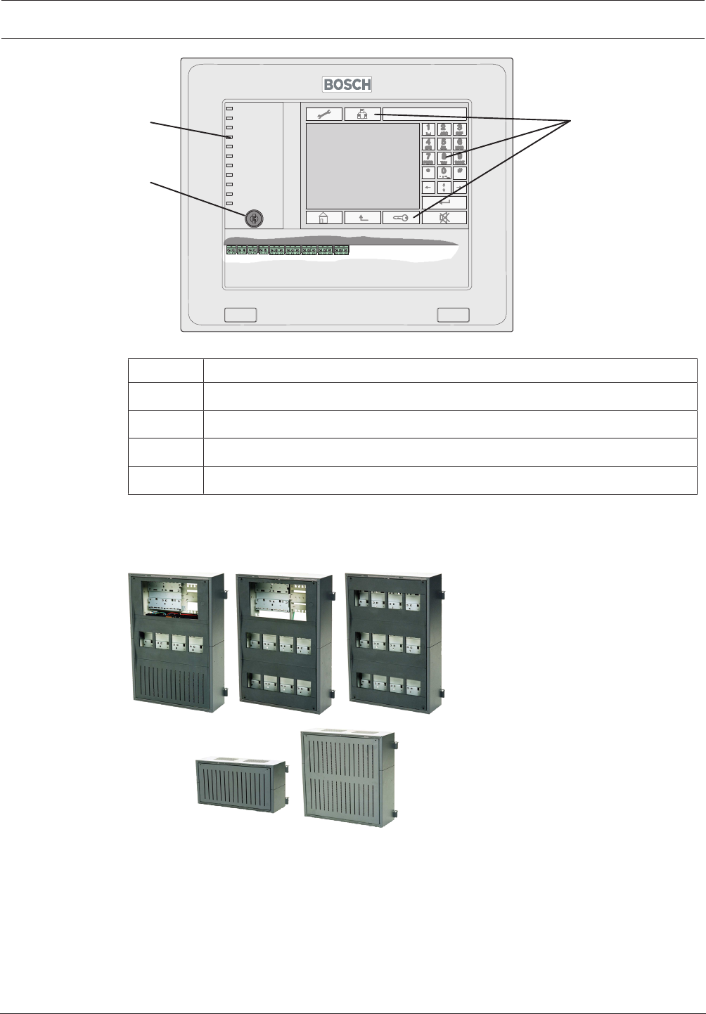
2.3 Remote Keypad
The FMR-5000-C Remote Keypad can be used to perform the same operating procedures as
the panel itself, enabling a networked system to be operated decentrally.
Power can be supplied by the panel or an external power supply unit such as the FPP-5000.
The easy-to-install housing was designed for tilted installation and for surface or flush wall
mounting.
Modular Fire Panel Product Description | en 13
Bosch Sicherheitssysteme GmbH System Information 09.2017 | 11.3 | F.01U.028.089
2
3
41
Figure2.4: FMR-5000-C Remote Keypad
Position Description
1 Touch screen
2 Membrane keys
3 LEDs for displaying the operating status
4 Key switch
Information on installing the Remote Keypad can be found in Remote Keypad, page 127.
The technical data can be found in Remote Keypad, page 149.
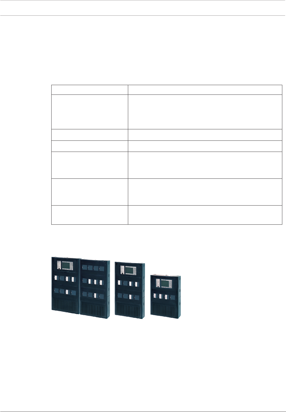
2.4 Housings for Frame Installation
Figure2.5: Housings for frame installation
Frame installation housings are always used in conjunction with the associated mounting
frame.
The housings are hooked into the mounting frame and can be swiveled to the front for
installation and servicing. The mounting frames are screwed to the wall surface and hold the
pre-cabling.
Alternatively to surface mounting, installation in 482.6mm (19") racks is also possible using
special installation kits.
12V/45Ah batteries can be used in the frame installation housing.

14 en | Product Description Modular Fire Panel
09.2017 | 11.3 | F.01U.028.089 System Information Bosch Sicherheitssysteme GmbH
The modular system makes it easy to extend the system.
Housing Designs and Combinations
Two frame installation housings are available as a base unit:
– CPH0006A (for 6 modules) or
– MPH0010A (for 10 modules)
These housings can accommodate an MPCPanel Controller with an operating and display unit.
The CPH0006A and MPH0010A basic housings can be extended to meet individual
requirements using:
– EPH0012A extension housing for an additional 12 modules, frame installation
– PSF0002A or PMF0004power supply housing for two or four 12V/45Ah batteries
respectively and an additional power supply unit.
– USF0000A Universal Housing Small, Frame Installation.
A power supply bracket for a UPS power supply is fitted ex-works in housing units
CPH0006A, PSF0002A and PMF0004A.
Mounting Frames
All mounting frames have integrated terminal blocks for the mains supply, integrated junction
boards, as well as permanently installed cable ducts to facilitate clear and tidy cable routing.
The mounting frames are available in three sizes:
– FBH0000A Mounting Frame Large
– FMH0000A Mounting Frame Medium
– FSH0000A Mounting Frame Small
The large mounting frame is also available in a design with a distributor rail complying with
EN60715:
– FHS0000A Mounting frame large with distributor rail
The housings for frame installation require the following mounting frames for surface-mounted
version:
Housing type Mounting frames
CPH 0006 A FBH 0000 A / FHS 0000 A
MPH 0010 A FBH 0000 A / FHS 0000 A
EPH 0012 A FBH 0000 A / FHS 0000 A
PSF 0002 A FSH 0000 A
PMF 0004 A FMH 0000 A
USF 0000 A FSH 0000 A
Notes:
– All mounting frames have an opening for routing cables that is sealed with an insert. Pre-
punched cable entries can be created from this insert.
– The FBH0000A and FHS0000A mounting frames are equipped with an earth bar ex
works.
– For the FMH0000A, the FPO‑5000‑EB Earth Bar can be ordered as an extension if
required.
– For continuous installation in combination, all mounting frames have T-shaped guide rails
on the base and T-shaped grooves on the top.

Modular Fire Panel Product Description | en 15
Bosch Sicherheitssysteme GmbH System Information 09.2017 | 11.3 | F.01U.028.089
Mounting Plate
An HMP0003A Mounting plate can be mounted in large mounting frames FBH0000A and
FHS 0000 A; this mounting plate can be individually equipped. It contains fixing holes for a
distributor rail.
USF 0000 A is fitted with a mounting plate ex works, which can be equipped as required. It
contains fixing holes for two distributor rails.
Equipment Limits
The table below shows the maximum number of:
– Modules
– Panel rails (short PRS-0002-C, long PRD 0004 A)
Housing type Modules Short rails Long rails
CPH 0006 A 6 1 1
MPH 0010 A 10 1 2
EPH 0012 A 12 - 3
PSF 0002 A - - -
PMF 0004 A - - -
USF 0000 A - - -
The table below shows the maximum number of:
– Panel controllers
– UPS power supply units
– Batteries
Housing type MPC UPS power
supply units
Batteries
CPH 0006 A 1 1 2x45Ah
MPH 0010 A 1 - -
EPH 0012 A - - -
PSF 0002 A - 1 2x45Ah
PMF 0004 A - 1 4x45Ah
USF 0000 A - - -
Installation Kits for 48cm (19") racks
Special installation kits are available for installing the frame installation housing in 482.6mm
(19") racks:
Housing type Installation kit, 482.6mm
CPH 0006 A FRB 0019 A
MPH 0010 A FRB 0019 A
EPH 0012 A FRB 0019 A
PSF 0002 A FRB 0019 A
PMF 0004 A FRM 0019 A
USF 0000 A FRS 0019 A
16 en | Product Description Modular Fire Panel
09.2017 | 11.3 | F.01U.028.089 System Information Bosch Sicherheitssysteme GmbH
No mounting frame is required when using the 482.6mm installation kits.
Front Doors
The CPH0006A, MPH0010A and EPH0012A housings can be equipped with optional
transparent front doors made of impact-resistant plastic, with a lock on the left or right:
– FDT 0000A Front Door Transparent, lock right side
– FDT 0003A Front Door Transparent, lock left side
Scope of Delivery
Housing type Scope of delivery (each x 1)
CPH 0006 A - Housing, painted sheet steel
- Power supply bracket
- Sheet steel front panel with plastic cover
- Accessories pack with installation material
MPH 0010 A - Housing, painted sheet steel
EPH 0012 A - Housing, painted sheet steel
PSF 0002 A - Housing, painted sheet steel
- Power supply bracket
- Cable set for battery connection
PMF 0004 A - Housing, painted sheet steel
- Power supply bracket
- Cable set for battery connection
USF 0000 A - Housing, painted sheet steel
- Mounting plate
The technical data for the frame installation housings can be found in Housings for Frame
Installation, page 146.
2.5 Housings for Wall Mounting
Figure2.6: Housings for wall mounting
Wall mounting housings are screwed directly onto the wall. This reduces the installation depth
by approx. 9cm, although the smaller 12V/28Ah batteries must be used as a result.
The modular system makes it easy to extend the system.
Housing Designs and Combinations
Two wall mounting housings are available as a base unit:
– HCP0006A (for 6 modules), and
– HBC0010A (for 10 modules)
These housings can accommodate an MPCPanel Controller with operating and display unit as
the central element.

Modular Fire Panel Product Description | en 17
Bosch Sicherheitssysteme GmbH System Information 09.2017 | 11.3 | F.01U.028.089
The HCP0006A and HBC0010A basic housings can be extended to meet individual
requirements using:
– HBE0012A Modular Extension Housing for an additional 12modules, and 2 x 12V/28Ah
batteries
– PSS0002A or PSB0004A Power Supply housings for additional power supply units and
12V/28Ah batteries
– DIB0000A Distribution Box
The DIB 0000 A Distribution Box is equipped with a distributor rail and is used to install
terminal strips.
Equipment Limits
The table below shows the maximum number of:
– Modules
– Panel rails (short PRS-0002-C, long PRD 0004 A)
Housing type Modules Short rail Long rail
HCP 0006 A 6 1 1
HBC 0010 A 10 1 2
HBE 0012 A 12 - 3
PSS 0002 A - - -
PSB 0004 A - - -
DIB 0000 A - - -
The table below shows the maximum number of:
– Panel controllers
– UPS power supply units
– Batteries
Housing type MPC UPS power supply
units
Batteries
HCP 0006 A 1 1 2x28Ah
HBC 0010 A 1 1 2x28Ah
HBE 0012 A - 1 2x28Ah
PSS 0002 A - 1 2x28Ah
PSB 0004 A - 1 4x28Ah
DIB 0000 A - - -
Installation Types
Various types of installation are possible:
– Surface mounted
– Installation in 482.6mm (19") racks
For surface mounting, the housing is mounted directly on the wall. For installation in
482.6mm (19") racks, the FRK0019A installation kit is used.
The housings have pre-formed cable bushings.
Front Doors
The housings can also be equipped with transparent front doors. The doors are made of
impact-resistant plastic and are available in two sizes (each with a lock on the left or right).
18 en | Product Description Modular Fire Panel
09.2017 | 11.3 | F.01U.028.089 System Information Bosch Sicherheitssysteme GmbH
Housing type Front door, lock left side Front door, lock right side
HCP 0006 A FDT 0003 A FDT 0000 A
HBC 0010 A FDT 0002 A FDT 0001 A
HBE 0012 A FDT 0002 A FDT 0001 A
The technical data for the housings can be found in Housings for Wall Mounting, page 146.
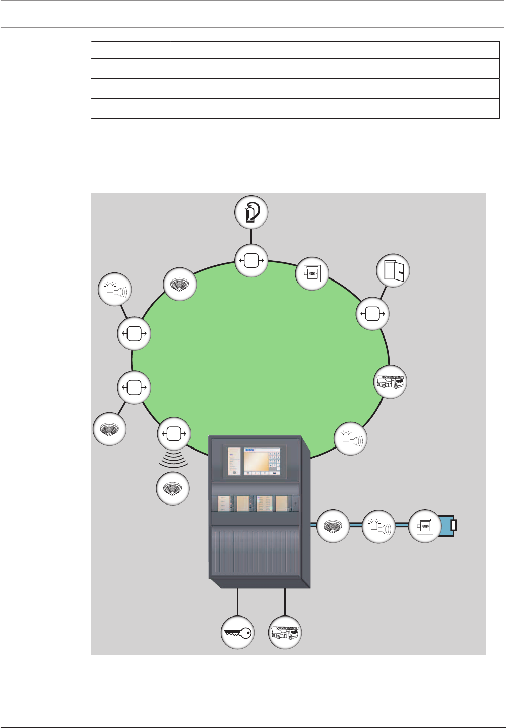
2.6 System Overview of FPA-5000 with Peripherals
The following figure shows a typical fire detection system design using an FPA-5000 Fire
Panel.
EOL
LSN improved/classic
1
2
Figure2.7: System overview of FPA-5000 with peripherals
Position Description
1 LSN loop (classic or improved version)

Modular Fire Panel Product Description | en 19
Bosch Sicherheitssysteme GmbH System Information 09.2017 | 11.3 | F.01U.028.089
Position Description
2 Conventional stub with EOL resistor or EOL module
(optional: conventional loop)
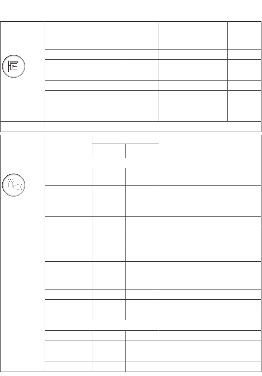
The tables below list the various product groups with all compatible peripheral elements from
our current range.
The devices approved for connection to the CZM 0004 A Conventional Module or the
FLM-420/4‑CON Conventional Interface Module can be found in the relevant compatibility
lists:
Module/interface module Compatibility list
CZM 0004 A F.01U.164.327
FLM-420/4‑CON F.01U.079.455
The current versions of the compatibility lists are available on the Internet (see Additional
Documentation, page 143).

20 en | Product Description Modular Fire Panel
09.2017 | 11.3 | F.01U.028.089 System Information Bosch Sicherheitssysteme GmbH
Product group Product name LSN 0300 A / LSN 1500 A CZM 0004 A FLM-420/4‑CO
N
FK100LSN
improved classic
Automatic fire
detectors
Point detectors
FAP-420/FAH-420 • •
AVENAR detector
4000
• •
FAP-520 • •
FCP-500 • •
FCP-320/FCH-320 • •
DO1101A-Ex •1)
RF smoke detectors
DOW 1171 •
Aspirating smoke detector
FAS-420-TM • •
FAS-420-TP/-TT • •
Linear smoke detectors
Fireray 50/100RV • •
FIRERAY3000 • •
FIRERAY5000 • •
Linear heat detectors
FCS-LWM-1 • •
ADW 511A •
N4387A • •
Infrared flame detectors
DF1192 •
DF1101A-Ex •1)
016519 • •
016589 • •
Duct smoke detectors
FAD-420-HS-EN • •
1) Connection via DCA1192/SB3 only
Modular Fire Panel Product Description | en 21
Bosch Sicherheitssysteme GmbH System Information 09.2017 | 11.3 | F.01U.028.089
Product group Product name LSN 0300 A / LSN 1500 A CZM 0004 A FLM-420/4‑CO
N
FK100LSN
improved classic
Manual call
points
FMC-420RW • •
FMC-210-DM • •
FMC-210-SM • •
FMC-300RW • •
FMC-120-DKM • •
SMF 121 •
DKM 2014/2-ex •1)
DM 1103 B-Ex •1)
1) Connection via DCA1192/SB3 only
Product group Product name LSN 0300 A / LSN 1500 A FLM-420-
NAC/ NZM
0002 A
FLM-420/4‑CO
N/
CZM0004A
RMH0002A
improved classic
Notification
appliances
Audible notification appliances
MSS300-SA/WS-
EC
•
MSS300-WS • •
MSS400 LSN •
MSS401 LSN •
FNM-320 •
FNM-320V-A-RD/
WH / -B-RD
•
ROLP-W-LX/ROLP-
R-LX
•
FNM-420-A/-B/-A-
BS
• •
FNM-420U-A • •
FNM-420V-A • •
DS 10 •
HPW 11 •
Visual notification appliances
FNS-320 •
FNS-P400RTH •
FNS-420-R • •
SOL-LX •
22 en | Product Description Modular Fire Panel
09.2017 | 11.3 | F.01U.028.089 System Information Bosch Sicherheitssysteme GmbH
Product group Product name LSN 0300 A / LSN 1500 A
improved classic
Interface
modules
FLM-420/4-CON • •
FLM-420-NAC • •
FLM-I 420-S • •
FLM-420-RHV • •
FLM-420-RLV1 • •
FLM-420-RLV8-S • •
FLM-420-I8R1-S • •
FLM-420-I2 • •
FLM-420-O2 • •
FLM-420-O8I2-S • •
FLM-420-O1I1 • •
FLM-420-RLE-S • •
FK 100 LSN •
Product group Product name Connection via
Fire service
devices
FBF 100 LSN LSN classic
FAT2002
FAT2002 RE (+ ADP-NB2)
– IOS 0020 A + IOP 0008 A
– IOS 0020 A + FLM-420-I2
– IOS 0020 A + FLM-420-I8R1
– IOS 0020 A + FLM-420-O1I1
– IOS 0020 A + FLM-420-O8I2
– IOS 0020 A + MPC
FMF-ADP-TTY – FPE-5000-UGM
– IOS 0020 A
FMF-FAT/FMF-FBF-FAT FMF-ADP-TTY
FMF-FIBS-A4/FMF-FIBS-A3 FMF-ADP-TTY
FMF-ESPA – FMF-ADP-TTY
– FMF-FAT/FMF-FBF-FAT
– FMF-FIBS-A4/FMF-FIBS-A3
2) Included in the scope of delivery of the FAT2002 RE
Modular Fire Panel Product Description | en 23
Bosch Sicherheitssysteme GmbH System Information 09.2017 | 11.3 | F.01U.028.089
Product group Product name Connection via
Transmission
devices
AT3000 IP/GSM
AT3000 IP/GSM/Analog
AT3000 IP/GSM/ISDN
ENO 0000 B
Key deposits Connection via: ENO 0000 B
Door controls Connection via: – FAA-MSR 420
– FLM-420-RHV
2.7 Networking
Notice!
You will find detailed information about the CAN and Ethernet networking of the panels in the
Networking Guide available for download at www.boschsecurity.com.
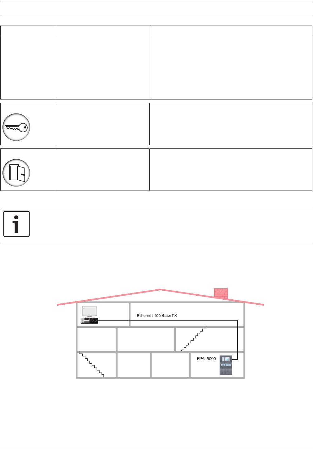
2.8 Connection to BIS
The MPCPanel Controller can be connected to a building management system (BIS) via an
Ethernet connection and an OPC server.
The connection must be enabled with an ADC-5000-OPC license key (see ).
BIS
Figure2.8: Connection to BIS
For a multiple-building network, it is essential to clarify with the network administrator:
– whether the network is designed for multiple-building connections (e.g. there must be no
technical interference due to differences in grounding potential)
– whether the bus users are designed for this kind of network (e.g. sufficient bandwidth).
24 en | Planning Modular Fire Panel
09.2017 | 11.3 | F.01U.028.089 System Information Bosch Sicherheitssysteme GmbH
Notice!
For detaiIed information about the installation und configuration of the OPC server see the
FSM-5000-OPC-Server manual.
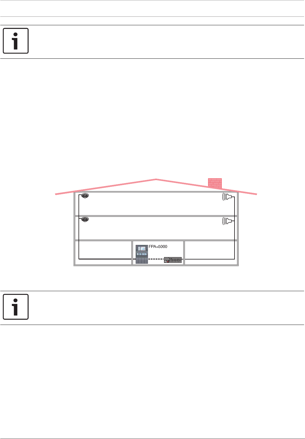
2.9 Connecting a Voice Alarm System
The Praesideo/PAVIRO or Plena voice alarm system can be connected via a data transmission
line to the FPA-5000 system. This enables the FPA-5000 to control voice alarm zones. The
control can be defined down to the individual detector level.
– For connection to the Praesideo/PAVIRO systems the Ethernet interface and IP protocols
are used. The voice alarm system can be configured for up to 244 virtual VAS triggers. You
will find detailed information in the Networking Guide which is available for download at
www.boschsecurity.com.
– For connection to a Plena system the RS232 interface on the IOS 0020 A or IOS 0232 A is
used. The Plena system can be configured for up to 120 virtual VAS triggers. You will find
detailed information in the Wiring Guide which can be found on the Extranet
www.boschbuildingsecurity.de/extranet.
The virtual VAS triggers are programmed using the FSP-5000-RPS programming software.
Plena
RS232
LSN
≤ 3m
Figure2.9: Connecting a Plena Voice Alarm System
3 Planning
Notice!
Planning Software by Bosch can be used to plan fire alarm systems that conform to the
relevant limits (e.g. in terms of cable length, power supply and energy requirement).
3.1 General Information
– Country-specific standards and guidelines must be considered during planning.
– The regulations issued by regional authorities and institutions (e.g. fire service) must be
adhered to.
– Please note that standards and guidelines may require that a maximum of one function in
more than one zone may fail.
For example, if the auxiliary power fails, only the fire detectors and/or manual call points
of one zone may fail.
– We recommend the use of loops wherever possible, as they offer far greater security than
stub lines.

Modular Fire Panel Planning | en 25
Bosch Sicherheitssysteme GmbH System Information 09.2017 | 11.3 | F.01U.028.089
– Terminating each stub and each T-tap with EOL modules is essential to set up a complete
fire alarm system complying with EN 54-13.
– Conventional detectors approved for the FPA-5000 can be connected using one of the
following methods:
– Using the CZM 0004 A 4 Zone Conventional Module
The module provides four DC primary lines (zones).
– Using an FLM-420/4‑CON GLT interface module on the LSN bus for two zones
– Consider the system limit for the number of LSN elements.
– When selecting the address cards, note:
Each element and input which is able to set off an alarm requires a detection point.
Inputs are considered as detection points if they are programmed accordingly using the
FSP-5000-RPS Programming Software. Refer to Detection Points, page 27.
– In accordance with EN 54-2, no more than 512 detectors and their functions may fail if a
system component fails. The corresponding measures are described under Redundancy,
page 40 .
– 12V/45Ah batteries can only be used with the frame installation housings.
– Use fuses complying with national regulations to protect the power lines.
– Recommended fire detector cable: J-Y(St)Y 2 x 2 x 0,8mm, red.
LSN Modules
– It is possible to combine LSN interface modules, LSN detectors and notification
appliances on one loop or stub line.
– For a mixed connection of LSN classic elements and LSN improved elements, a maximum
of 127elements are permitted.
– The use of unshielded cables is possible.
– Limits per LSN0300 module:
– Up to 127LSN classic elements or 254LSN improved elements can be connected
– Current consumption of up to 300mA
– Cable length of up to 1600m (see also Achievable Cable Length with LSN0300A,
page 28)
– Limits per LSN1500 module:
– Up to 127LSN classic elements or 254LSN improved elements can be connected
– Up to 1500mA current consumption if LSN improved elements are connected
– Up to 300mA current consumption if LSN classic elements are connected
– Cable length of up to 3000m
– As stipulated by EN54‑2, systems with more than 512 LSN elements must be connected
redundantly. This is ensured by using a second basic housing with an additional panel
controller. A CRP0000A cable set is required for redundant connection.
Technical Data and System Limits
Refer to the system limits in System Limits, page 143.
The technical data for all components can be found in Technical Data, page 143.
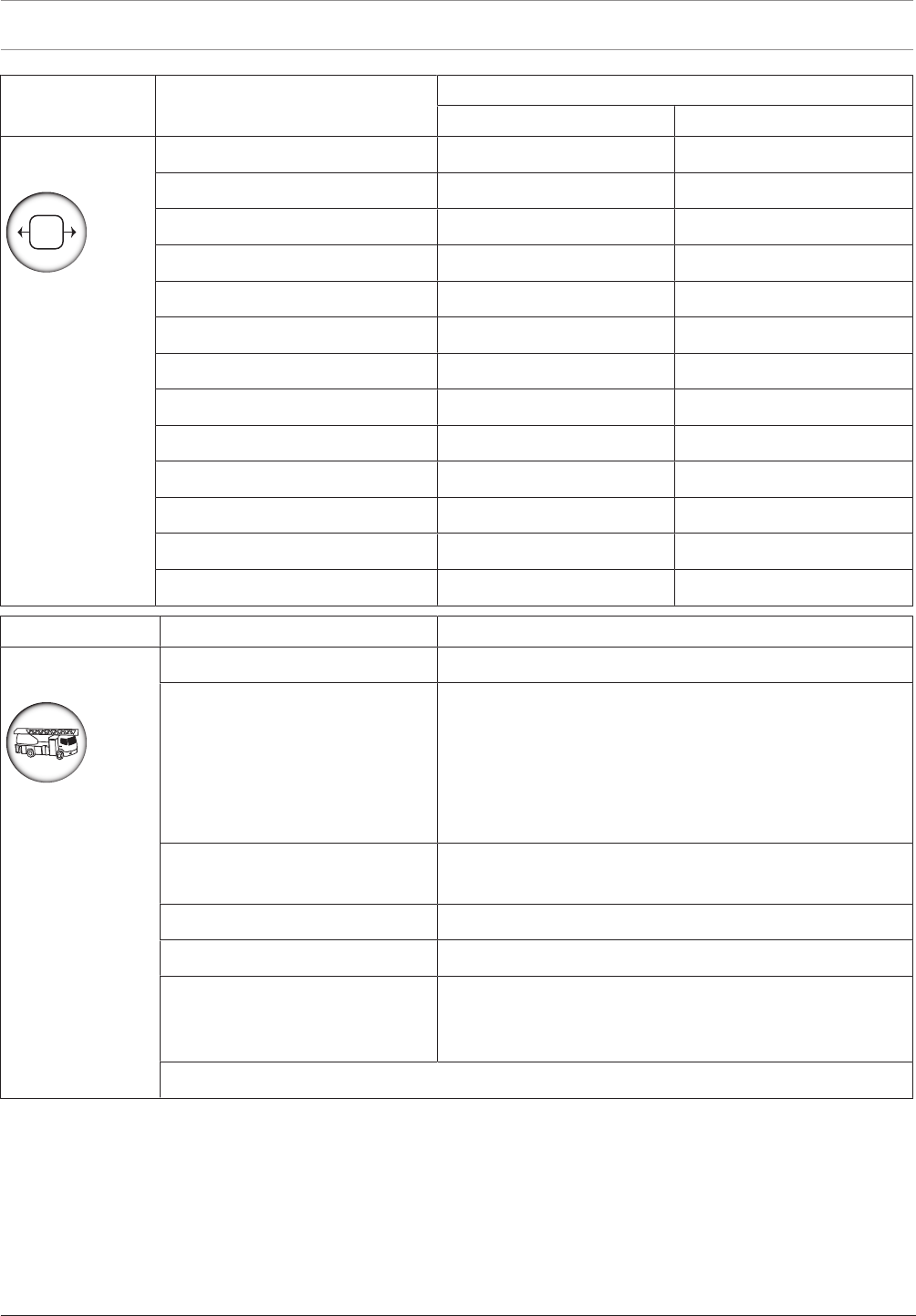
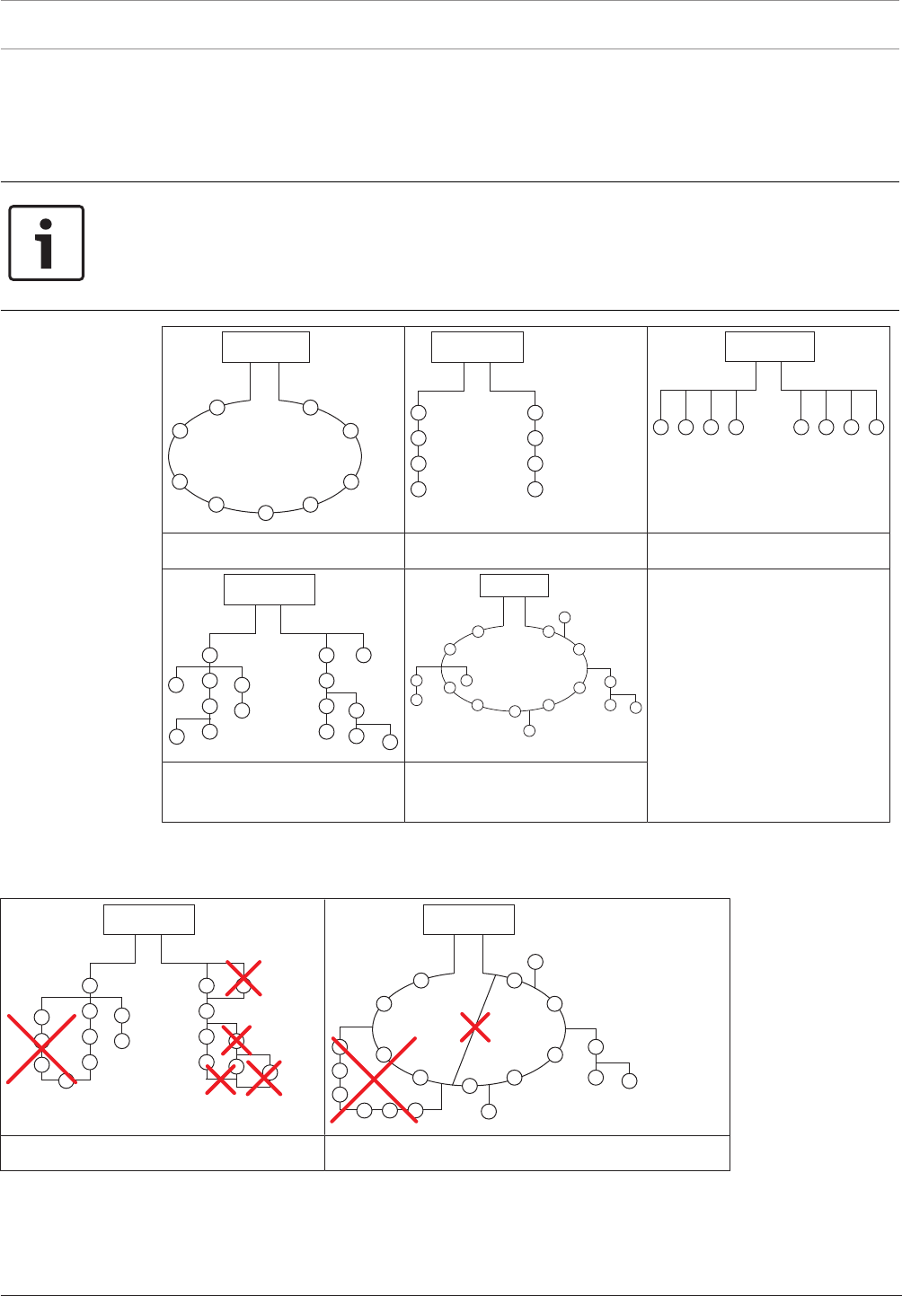
3.2 Structures in Local Security Network
In a Local Security Network (LSNclassic), fire detectors can be configured as a loop or as one
or two stubs.
In an improved version Local Security Network (LSNimproved), the detectors can be
configured as a loop, a stub or T-tap or in any mixed loop or T-tap structures. However, it is
important to note that mesh structures cannot be created.
26 en | Planning Modular Fire Panel
09.2017 | 11.3 | F.01U.028.089 System Information Bosch Sicherheitssysteme GmbH
The LSNimproved version allows T-taps on stubs or loops and any number of nodes, branches
per node and elements per branch as long as the maximum number of elements does not
exceed 254.
Connections can be positioned anywhere along the LSN line.
Notice!
Planning should take the anticipated total current and line resistance into account to ensure
each detector has an operating voltage of at least 15VDC.
As soon as an LSN classic device is in a loop or stub, only loop or stub structures can be
used. In this case, T-tapping is no longer possible.
FPA-5000
FPA-5000
FPA-5000
1: Loop 2: 1 or 2 stubs 3: T-tap
FPA-5000
FPA-5000
4: 1 or 2 stubs and T-taps
mixed
5: Loop and stubs mixed with
T-taps
Table3.1: Possible structures in LSN
When configuring the detectors, it is essential to ensure that no mesh structures are created.
FPA-5000
FPA-5000
Mesh structures within a stub structure Mesh structures within a loop structure
Table3.2: Unusable network structures

Modular Fire Panel Planning | en 27
Bosch Sicherheitssysteme GmbH System Information 09.2017 | 11.3 | F.01U.028.089
3.3 Detection Points
Each element or input that can trigger an alarm after programming requires its own detection
point. Detection points are enabled via address cards. One FPA‑5000 manages up to 4096
detection points.
All elements and inputs that do not use the Input type in the Message type setting are
regarded as detection points. Therefore, all elements and inputs for which one of the
following settings is programmed as the Message type are regarded as detection points:
– Fire
– Internal fire
– Building control
– Multi-criterion
– Smoke
– Fault
– Heat
– Water
Only some of these message types are available for selection depending on the element type.
The elements and inputs that can trigger an alarm include all manual and automatic detectors,
as well as the modules and interface modules listed below on the basis of the available inputs.
Modules Detection Points
CZM0004A Up to 4 (1 detection point per zone)
IOP0008A Up to 8 (1 detection point per monitored input)
ENO 0000 B requires 1 detection point only if a FSE release element is
connected and programmed using the FSP-5000-RPS
programming software
Interfaces Detection Points
FLM-420/4CON Up to 2
FLM-420-I8R1 Up to 8
FLM-420-I2 Up to 2
FLM-420-O8I2 Up to 2
FLM-420-O1I1 Up to 1
FLM-420-RLE-S Up to 2
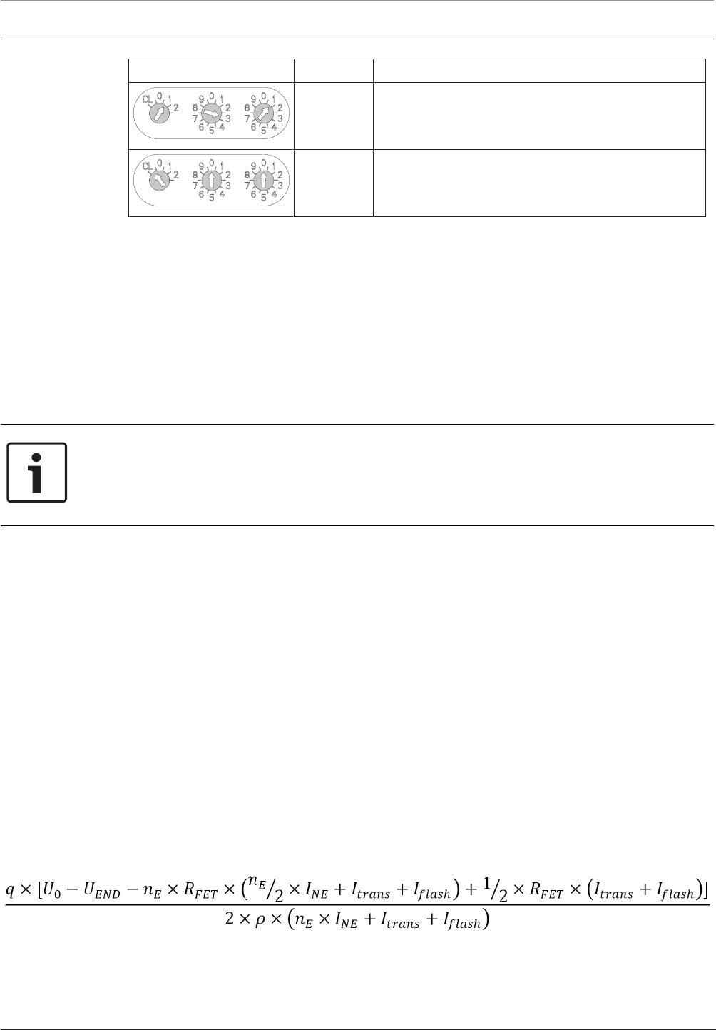
3.4 Addressing
LSN elements are addressed via rotary switches (e.g. FAP420) or DIP switches (e.g. E/W
versions of the FLM-420).
For the detectors, there are three rotary switches on the underside, which can be used to
select automatic or manual addressing with or without automatic detection.
The following settings are possible:
Rotary switch setting Address Operating mode
0 0 0 Loop/stub in LSNimproved version mode with
automatic addressing (T-tapping not possible)=
factory default setting
28 en | Planning Modular Fire Panel
09.2017 | 11.3 | F.01U.028.089 System Information Bosch Sicherheitssysteme GmbH
Rotary switch setting Address Operating mode
0 0 1
...
2 5 4
Loop/stub/T-tapping in LSNimproved version mode
with manual addressing (address shown in
example= 131)
CL 0 0 Loop/stub in LSNclassic mode with automatic
addressing (T-tapping not possible, maximum
number of elements= 127)
Table3.3: Addressing via rotary switches
The rotary switches are moved to the required position using a slotted-head screwdriver.
Automatic Addressing
If addresses are automatically allocated by a fire panel with LSN improved version technology,
all detectors must have the address "000" (factory default setting).
Manual Addressing
With manual addressing, the detector address is set using the three rotary switches. The right-
hand rotary switch is used to set the units, the central rotary switch is used to set the tens
and the left-hand rotary switch is used to set the hundreds.
Notice!
Using addresses greater than 254 is not permitted.
This will prompt the display of an error message on the fire panel.
With manual addressing, all the detectors in a loop, stub or T-tap must have an address
between 1 and 254.
From the LSN module software version 1.0.35 onwards, you can operate LSN improved
elements and LSN classic elements in combination in a loop or stub. If an LSN classic element
is present, only 127 elements can be used in the loop.
Note that structures with T-tapping are only possible if only LSN improved elements are used
(see Structures in Local Security Network, page 25).
For setting addresses with DIP switches, refer to the instructions in the installation guide
supplied with the products.
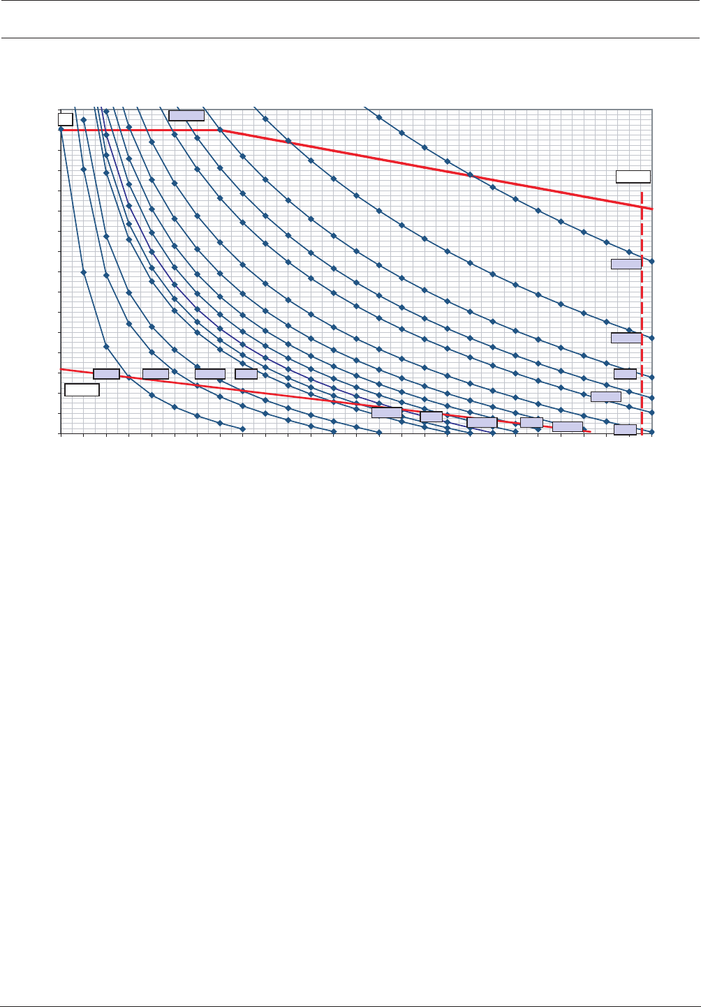
3.5 Achievable Cable Length with LSN0300A
The usable cable length depends essentially on the resistance of the cable and the quantity
and current consumption of the network elements. The way in which the elements are
distributed locally on the bus also makes a difference.
The possible cable length can be estimated using the formula below. This formula is also used
in the Planning Software by Bosch for fire alarm systems and is based on the critical
application situation where all network elements are concentrated at the end of the bus line.
The calculated cable lengths are therefore on the conservative side. The diagrams on and can
be used to make a quick estimate.
The following applies:
L = cable length to be calculated in[m]
U0 = bus voltage at the connection terminals = 30volt
UEnd = bus end voltage = 15volt (must not fall below this limit!)
q = cable cross section = 0.503mm2 (for cable Ø0.8mm)

Modular Fire Panel Planning | en 29
Bosch Sicherheitssysteme GmbH System Information 09.2017 | 11.3 | F.01U.028.089
nE = number of elements
ρ = specific resistance of copper = 0.0178Ωmm2/m)
RFET = FET resistance = 0.7Ω (LSN classic) or 0.35Ω (LSN improved),
INE = average current consumption of elements in[A]
Itrans = transmission current = 0.012A
Iflash = flash current = 0.018A
Note that the sum of non-isolated cables must not exceed the limit of 500m. The limit of
500m applies to:
– The lines on the inputs of the following modules: FLM-420-RHV, FLM-420-I2 , FLM-420-
I8R1-S, FLM-420-O8I2-S, FLM-420-O1I1, FLM-420-RLE-S
– The NAC line of the FLM-420-NAC module
– The lines to remote indicators: FAA-420-RI-DIN, FAA-420-RI-ROW
The limit of 500m non-isolated cables doesn't count for the conventional lines of the
FLM-420/4‑CON and the lines connected to the relay contacts and open collector outputs.
Note that the maximum cable length must not exceed 1600m.
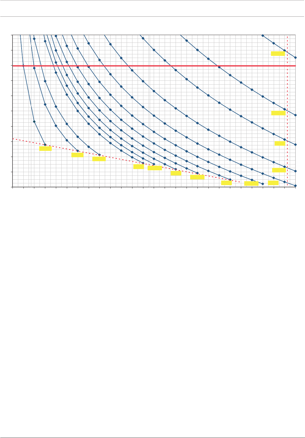
Using the Diagram for LSN classic
FET resistance = 0.7Ω, fire alarm cable with Ø0.8mm
Example 1:
You want to know the maximum cable length for a given number of network elements and a
given current consumption (nE=50, INE=3 mA). On the X axis, go vertically up at 50 until you
reach the 3mA curve. Then, from the point of intersection go horizontally to the left to the Y
axis and read off the maximum achievable cable length. In this example it is 840m.
Example 2:
You want to know the maximum number of network elements for a given cable length and an
average current consumption of the network elements (L=1000m, INE=20mA). Starting from
the Y axis at 1000, go horizontally across to the right as far as the 20mA curve and then from
the point of intersection vertically down to the X axis. Read off the maximum number of
network elements, in this example it is 8.
Notice!
Remote indicators activated by the detector C point:
A maximum additional cable length of 500m is allowed when using remote indicators (e.g.
FAA-420-RI-DIN/FAA-420-RI-ROW). The total length of installed cable must not exceed the
limit of 1600m.
30 en | Planning Modular Fire Panel
09.2017 | 11.3 | F.01U.028.089 System Information Bosch Sicherheitssysteme GmbH
0
0
02
0
04
006
00
8
00
01
00
21
00
41
0061
0081
0002
A
m7,0
Am1
Am
5
,1
A
m
02
Am01
A
m5
,
7
Am5
Am2
A
m4
Am
5,
4
Am5,2
A
m3
Am5,3
310210110010908070605
0
40302010
0
Am4,0
c
a
L [m]
N
b
Figure3.1: Diagram for determining the maximum achievable cable length: LSN classic elements with LSN 0300 A
L = cable length in meters
N = number of LSN classic elements
a = 1600m limit
b = 300mA limit
c = maximum possible number of LSN classic elements = 127
Modular Fire Panel Planning | en 31
Bosch Sicherheitssysteme GmbH System Information 09.2017 | 11.3 | F.01U.028.089
0
0
0
2
0
0
4
0
06
0
08
0
0
01
0021
0041
0061
0
0
81
0002
L [m]
0
52042032
0
22012
0
020
9
10
8
1
0
7
1
0
6
105
1
0410310
2
101
1
00109
080
706
0
50
4
0302
0
10
Am1
Am3
A
m4
A
m7
,0
Am2
Am5
,
2
Am5
Am01
Am02
A
m
5,7
Am562,0
Am573,0
Am5,0
Am5,1
N
a
b
c
d
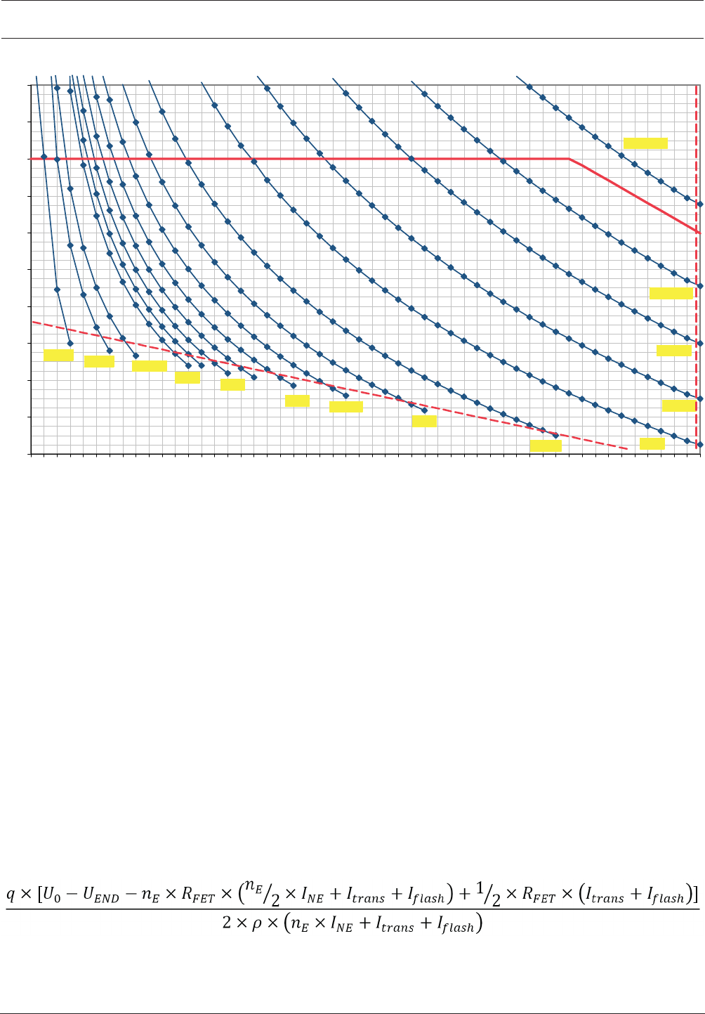
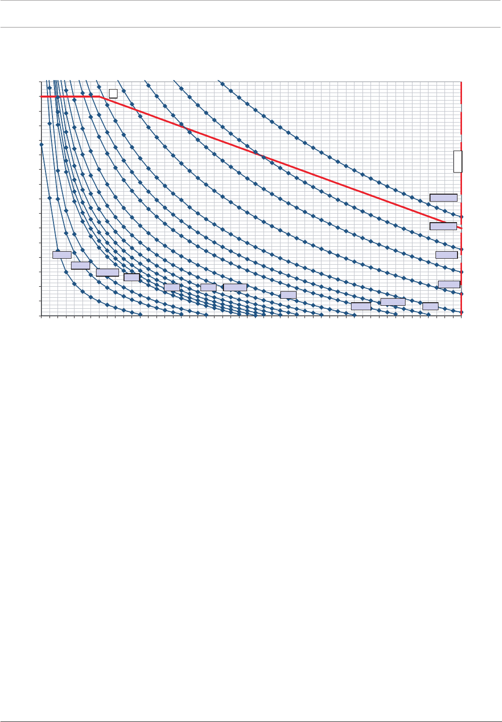
Figure3.2: Diagram for determining the maximum achievable cable length: LSN improved elements with LSN 0300 A
L = cable length in meters
N = number of LSN improved elements
a = 1600 m limit
b = bus dynamic limit
c = maximum possible number of LSN improved elements = 254
d = 300mA limit
3.6 Achievable Cable Length with LSN1500A
The usable cable length depends essentially on the resistance of the cable and the quantity
and current consumption of the network elements.
The way in which the elements are distributed locally on the bus also makes a difference. The
possible cable length can be estimated using the formula below. This formula is also used in
the Planning Software by Bosch for fire alarm systems and is based on the critical application
situation where all network elements are concentrated at the end of the bus line. The
calculated cable lengths are therefore on the conservative side.
The diagrams on pages and can be used to make a quick estimate.
The following applies:
L = cable length to be calculated in[m]
U0 = bus voltage at the connection terminals = 30volt
UEnd = bus end voltage = 15volt (must not fall below this limit!)

32 en | Planning Modular Fire Panel
09.2017 | 11.3 | F.01U.028.089 System Information Bosch Sicherheitssysteme GmbH
q = cable cross section = 0.503mm2 (for cableØ0.8mm)
nE = number of elements
ρ = specific resistance of copper = 0.0178mm2/m)
RFET = FET resistance = 0.7Ω (LSN classic) or 0.35Ω (LSN improved),
INE = average current consumption of elements in[A]
Itrans = transmission current = 0.012A
Iflash = flash current = 0.018A
Note that the sum of non-isolated cables must not exceed the limit of 500m. The limit of
500m applies to:
– The lines on the inputs of the following modules: FLM-420-RHV, FLM-420-I2 , FLM-420-
I8R1-S, FLM-420-O8I2-S, FLM-420-O1I1, FLM-420-RLE-S
– The NAC line of the FLM-420-NAC module
– The lines to remote indicators: FAA-420-RI-DIN, FAA-420-RI-ROW
The limit of 500m non-isolated cables doesn't count for the conventional lines of the
FLM-420/4‑CON and the lines connected to the relay contacts and open collector outputs.
Note that the maximum cable length must not exceed 3000m.
Using the Diagram for LSN improved
FET resistance = 0.35Ω, fire alarm cable with Ø0.8mm
Example 1:
You want to know the maximum cable length for a given number of network elements and a
given current consumption (nE=120, INE=0.5mA). On the X axis, go vertically up at 120 until
you reach the 0.5mA curve. Then, from the point of intersection go horizontally to the left to
the Y axis and read off the maximum achievable cable length. In this example it is 1950 m.
Example 2:
You want to know the maximum number of network elements for a given cable length
(L=1000m, INE=2mA). Starting from the Y axis at 1000, go horizontally across to the right as
far as the 2mA curve and then from the point of intersection vertically down to the X axis.
Read off the maximum number of network elements, in this example it is 73.
Notice!
Remote indicators activated by the detector C point:
A maximum additional cable length of 500m is allowed when using remote indicators (e.g.
FAA-420-RI-DIN/FAA-420-RI-ROW).
The total length of installed cable must not exceed the limit of 3000m.
Modular Fire Panel Planning | en 33
Bosch Sicherheitssysteme GmbH System Information 09.2017 | 11.3 | F.01U.028.089
0
200
400
600
800
1000
1200
1400
1600
1800
2000
2200
2400
2600
2800
3000
3200
0 5 10 15 20 25 30 35 40 45 50 55 60 65 70 75 80 85 90 95 100 105 110 115 120 125 130
N
L [m]
0,7mA
1mA
1,5mA
20mA
10mA
7,5mA
5mA
2mA
4mA
4,5mA
2,5mA
3mA
3,5mA
b = 127
1,25mA
0,4mA
300mA
a
Figure3.3: Diagram for determining the maximum achievable cable length: LSN classic elements with LSN 1500 A
L = cable length in meters
N = number of LSN classic elements
a = 3000m limit
b = maximum possible number of LSN classic elements = 127
34 en | Planning Modular Fire Panel
09.2017 | 11.3 | F.01U.028.089 System Information Bosch Sicherheitssysteme GmbH
0
200
400
600
800
1000
1200
1400
1600
1800
2000
2200
2400
2600
2800
3000
3200
0 10 20 30 40 50 60 70 80 90 100 110 120 130 140 150 160 170 180 190 200 210 220 230 240 250
N
L [m]
1mA
3mA
4mA
1,5mA
0,7mA
2mA
2,5mA
5mA
10mA
20mA
7,5mA
a
b =254
1,25mA
0,5mA
0375mA
0,265mA
Figure3.4: Diagram for determining the maximum achievable cable length: LSN improved elements with LSN 1500 A
L = cable length in meters
N = number of LSN improved elements
a = Bus dynamic limit
b = maximum possible number of LSN improved elements = 254
Modular Fire Panel Planning | en 35
Bosch Sicherheitssysteme GmbH System Information 09.2017 | 11.3 | F.01U.028.089
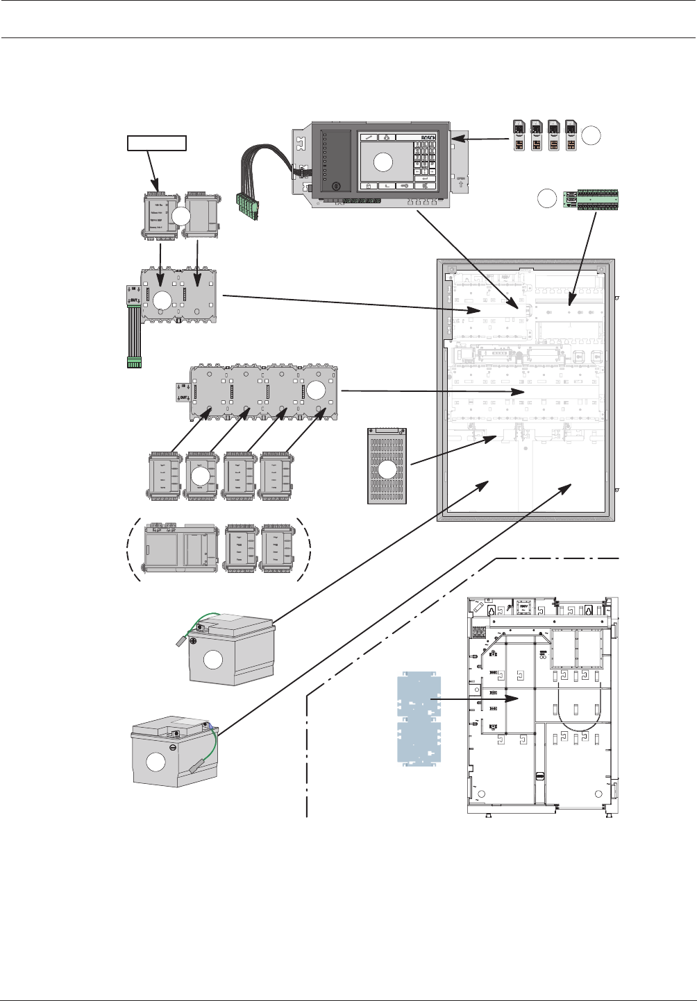
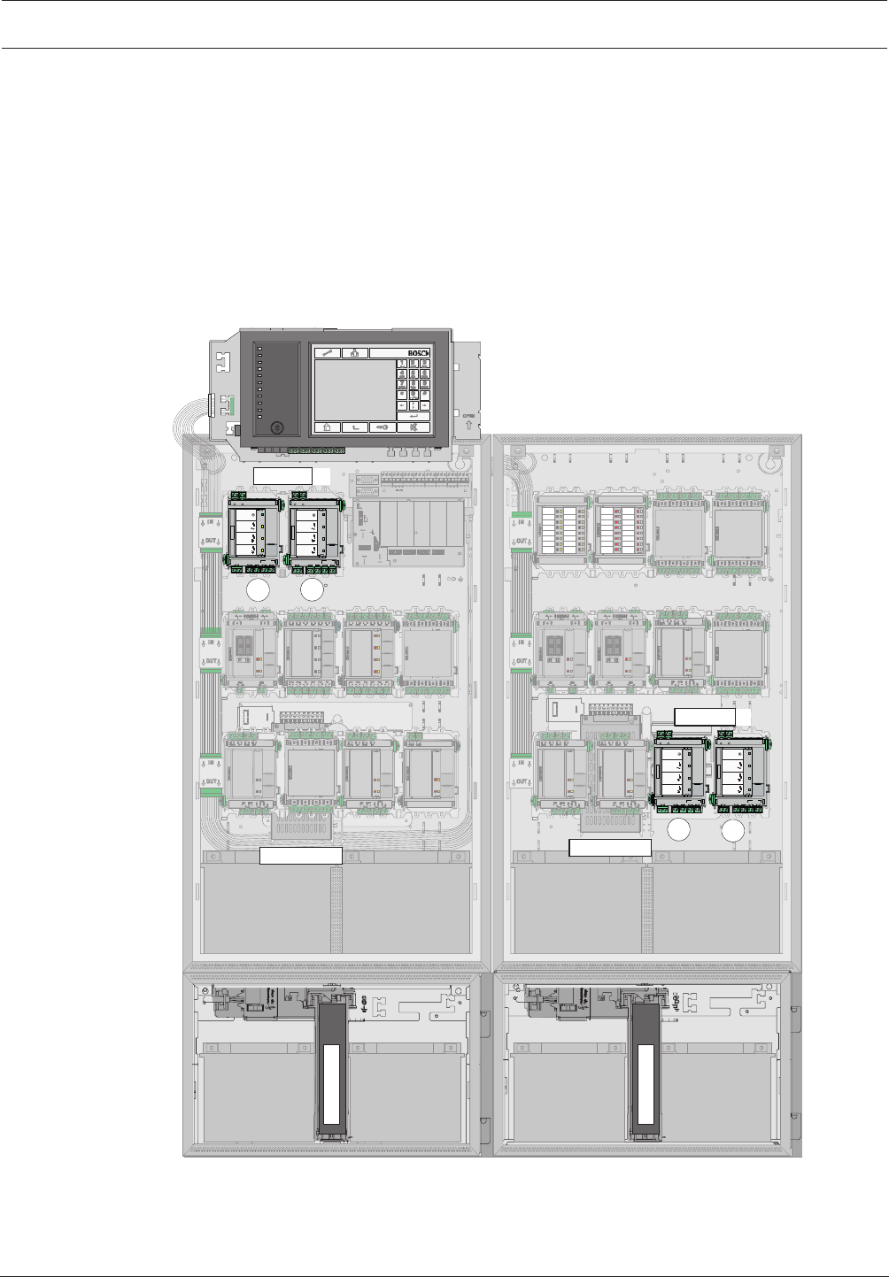
3.7 Examples of Housing Equipment
CPH0006A, Fully Configured Panel, with Installation Sequence
UPS 2416 A
PRD 0004 A
PRS-0002-C
MPC
RLE 0000 A
ADC xxxxx A
CPH 0006 A
1
2
4
5
6
3
9
BCM-0000-B
12 V / 45 Ah
7
12 V / 45Ah
8
<= 4 Module
10
FBH 0000 A / FHS 0000 A
HMP 0003 A
Figure3.5: Example of configuration with CPH0006A frame installation housing for 6modules
36 en | Planning Modular Fire Panel
09.2017 | 11.3 | F.01U.028.089 System Information Bosch Sicherheitssysteme GmbH
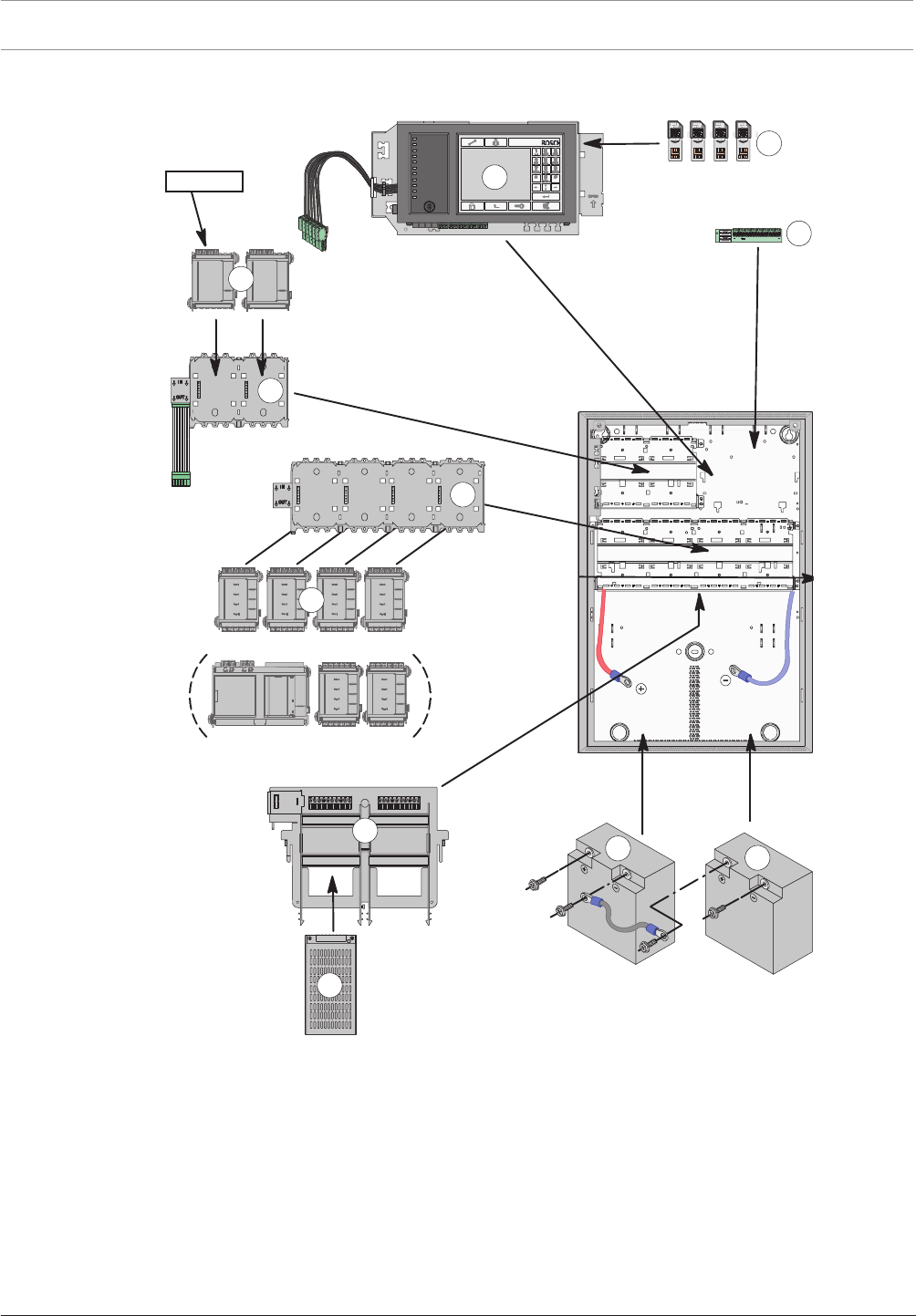
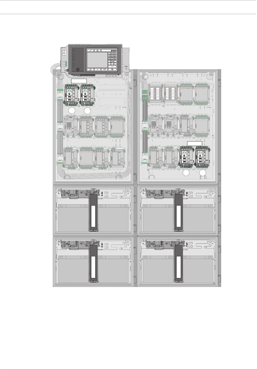
HCP0006A, Fully Configured Panel, with Installation Sequence
MPC
UPS 2416 A
PRS-0002-C
RLU 0000 A
ADC xxxxx A
HCP 0006 A
<= 4 Module
FPO-5000-PSB-CH
2
4
5
6
9
10
11
12 V / 28 Ah
12 V / 28 Ah
8
7
BCM-0000-B
PRD 0004 A
3
1
Figure3.6: Example of configuration with HCP0006A Modular Panel Housing for 6 Modules
3.8 Configuration of BCM Battery Controller Module
The panel can be powered by up to 8 BCM-0000-B Battery Controller Modules, each with its
own UPS2416A Universal Power Supply. Current consumption is equally distributed among
all battery controller modules.
Notes
– The 24V switch outputs may not be connected in parallel.
– The total current for all connected components including the battery charge current may
not exceed 6A.
Modular Fire Panel Planning | en 37
Bosch Sicherheitssysteme GmbH System Information 09.2017 | 11.3 | F.01U.028.089
– The batteries connected to the BCM must all be of the same type and have identical
electrical properties.
– The cable length at the switch outputs for faults may not exceed 3meters.
– The cables for the switch outputs for faults may only be routed inside the housing.
Information on installation of the BCM module can be found in BCM‑0000‑B Battery Controller
Module, page 101.
Configuration with One to Four BCM Modules in Wall Mounting Housings
– Up to 2 BCM-0000-B modules on short panel rail
– Maximum 2 BCM-0000-B modules at the end of the long panel rail
– Each BCM-0000-B module requires one UPS 2416 A Universal Power Supply.
1. 2.
BCM 0000
HCP 0010 A
UPS 2416 A 12 V / 24 Ah12 V / 24 Ah
12
BCM
34
BCM
UPS 2416 A UPS 2416 A
BCM 0000 B
+ - + -
24V 24V
MAIN BAT1 BAT2 FAULT
FAULT
AC
BAT
MAIN POWER
MAIN POWER
TROUBLE
TROUBLE
TROUBLE
BATTERY 1
BATTERY 2
+ - + - + - - - - +
S
1 2
BCM 0000 B
+ - + -
24V 24V
MAIN BAT1 BAT2 FAULT
FAULT
AC
BAT
MAIN POWER
MAIN POWER
TROUBLE
TROUBLE
TROUBLE
BATTERY 1
BATTERY 2
+ - + - + - - - - +
S
12
BCM 0000 B
+ - + -
24V 24V
MAIN BAT1 BAT2 FAULT
FAULT
AC
BAT
MAIN POWER
MAIN POWER
TROUBLE
TROUBLE
TROUBLE
BATTERY 1
BATTERY 2
+ - + - + - - - - +
S
1 2
BCM 0000 B
+ - + -
24V 24V
MAIN BAT1 BAT2 FAULT
FAULT
AC
BAT
MAIN POWER
MAIN POWER
TROUBLE
TROUBLE
TROUBLE
BATTERY 1
BATTERY 2
+ - + - + - - - - +
S
12
A6142SPU
A6
1
4
2SP
U
A
2
00
0S
S
P
12 V / 28 Ah12 V / 28 Ah 12 V / 28 Ah
12 V / 28 Ah12 V / 28 Ah12 V / 28 Ah12 V / 28 Ah
12 V / 28 Ah
Figure3.7: Configuration of 1 to 4 BCM modules (wall mounting)
Configuration with One to Four BCM Modules in Frame Installation Housings
– Up to 2 BCM-0000-B modules on short panel rail
– Maximum 2 BCM-0000-B modules at the end of the last long panel rail
38 en | Planning Modular Fire Panel
09.2017 | 11.3 | F.01U.028.089 System Information Bosch Sicherheitssysteme GmbH
– Each BCM-0000-B module requires one UPS 2416 A Universal Power Supply.
Depending on the back-up time, a PMF 0004 A housing may be required instead of the PSF
0002 A housing for the power supply.
12
BCM
BCM
4
3
A6142SPU
A6
1
4
2SP
U
A6142SPU
A61
4
2SPU
EPH 0012 A
MPH 0010 A
A2000FS
PA
2
0
00FS
P
12 V / 45 Ah12 V / 45 Ah 12 V / 45 Ah12 V / 45 Ah
12 V / 45 Ah12 V / 45 Ah 12 V / 45 Ah12 V / 45 Ah
Figure3.8: Configuration of 1 to 4 BCM modules (frame installation)
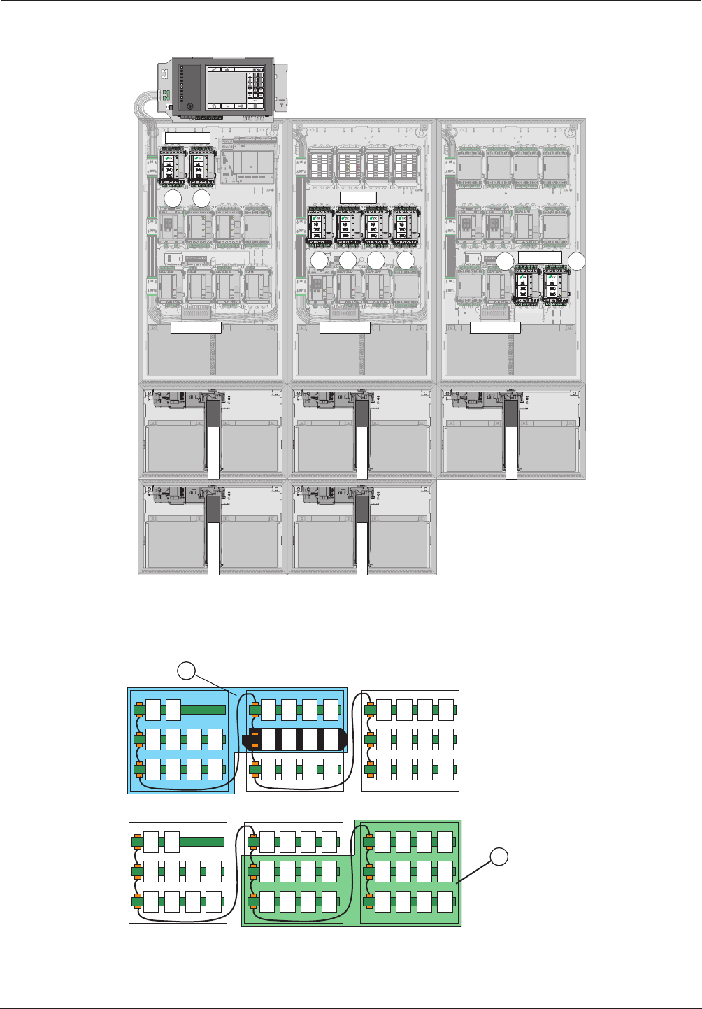
Configuration with 5 to 8 BCM Modules in Wall Mounting Housings
– 2 BCM-0000-B modules on short panel rail
– 2 BCM-0000-B modules at the end of the long panel rail
– The remaining BCM-0000-B modules on a panel rail in the center of the system.
– Each BCM-0000-B module requires one UPS 2416 A Universal Power Supply.
Modular Fire Panel Planning | en 39
Bosch Sicherheitssysteme GmbH System Information 09.2017 | 11.3 | F.01U.028.089
12
BCM
BCM
34
BCM
HBE 0012 A
A0100PCH
HBE 0012 A
UPS 2416 A
12 V / 28 Ah12 V / 28 Ah
12 V / 28 Ah 12 V / 28 Ah
12 V / 28 Ah 12 V / 28 Ah
UPS 2416 AUPS 2416 A
8
7
6
5
UPS 2416 A UPS 2416 A
12 V / 24 Ah12 V / 24 Ah 12 V / 24 Ah12 V / 24 Ah
A
6
1
42SPU
A6142SPU
A
2000SS
P
12 V / 28 Ah
12 V / 28 Ah 12 V / 28 Ah 12 V / 28 Ah
UPS 2416 A UPS 2416 A
12 V / 24 Ah12 V / 24 Ah 12 V / 24 Ah12 V / 24 Ah
A
6
1
42SPU
A6142SPU
A
2000SS
P
12 V / 28 Ah
12 V / 28 Ah 12 V / 28 Ah 12 V / 28 Ah
UPS 2416 A 12 V / 24 Ah12 V / 24 Ah
A6142SPU
12 V / 28 Ah 12 V / 28 Ah
Figure3.9: Configuration of 5 to 8 BCM modules (wall mounting)
Limits:
The current load on a panel rail may not exceed the maximum value of 12A.
The current load via a panel rail plug may not exceed the maximum value of 10A.
BCM
3
BCM
4
BCM
1
BCM
2
BCM
5
BCM
6
BCM
7
BCM
8
1
Figure3.10: Area1
BCM
3
BCM
4
BCM
1
BCM
2
BCM
5
BCM
6
BCM
7
BCM
8
2
Figure3.11: Area2

40 en | Planning Modular Fire Panel
09.2017 | 11.3 | F.01U.028.089 System Information Bosch Sicherheitssysteme GmbH
Standby Current Calculation to EN 54-4
Imax, Standby =CBatt -IAlarm x 0,5h
tStandby
Imax, A = 6A - 18h
CBatt
(1) (2)
Inom = min[Imax, Standby , Imax, A ]
(3)
Formula(1) describes the maximum system current to guarantee a particular back-up time
(Imax,Standby).
Formula(2) describes the maximum system current taking into account simultaneous battery
charging (Imax.A).
The system standby current (Inom) to be selected is calculated from the lower of the two
maximum system current values, as shown in the formula (3).
Parameters:
– tStandby = back-up time in hours
– IAlarm = maximum alarm current (Imax,B)
– CBatt = battery capacity in Ah
Possible capacities (CBatt):
– 24-26Ah or 36-45Ah with 2batteries
– 48-52Ah or 72-90Ah with 4batteries
3.9 Redundancy
Standards and guidelines (e.g. DIN VDE 0833-2, EN 54-2) require different, country-specific
redundancy conditions for specific applications:
– In the event of a system fault in the panel or the system, no more than 512 detectors may
fail (EN 54-2). In such cases, redundant system components must be used:
– Redundant panel controller
– Redundant connection to a Bosch UGM
– Redundant connection of the transmission device or AT3000, see the FPA-5000/
FPA-1200 wiring guide (document number F.01U.009.201)
– Activation of extinguishing systems in accordance with VdS 2496: If a signal processing
unit fails, no more than one extinguishing area may fail. In such cases, redundant system
components must be used:
– Redundant panel controller
– Redundant LSN 0300 A module when using more than one FLM-420-RLE-S in an LSN
loop
Redundant panel controller
For a redundant connection, a second basic housing with an additional panel controller and a
CRP 0000 A Cable Set is required, where applicable. The figure below shows a configuration
with a redundant panel controller. The slots (2) behind a redundant panel controller (1) must
not be occupied with modules.
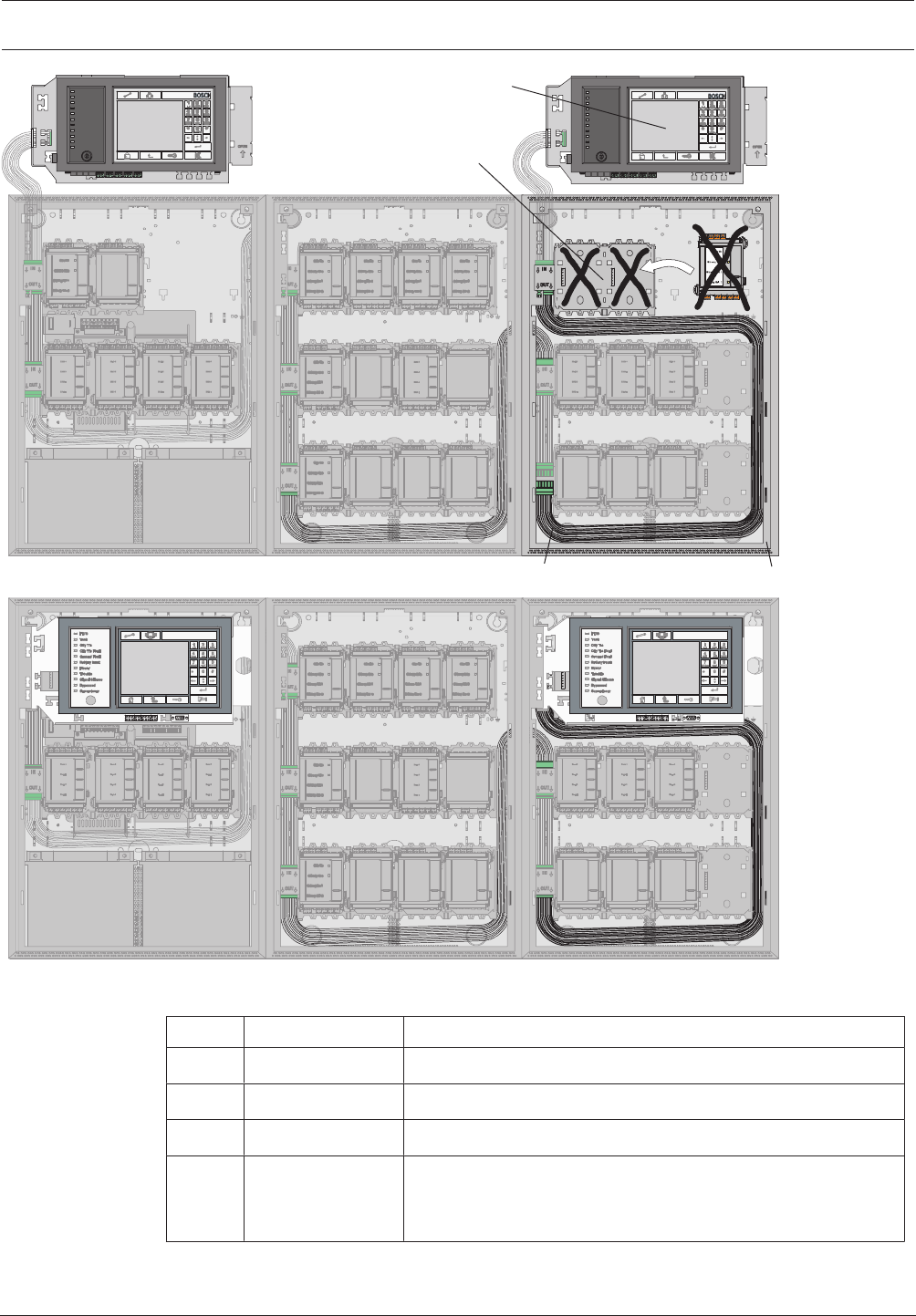
Modular Fire Panel Planning | en 41
Bosch Sicherheitssysteme GmbH System Information 09.2017 | 11.3 | F.01U.028.089
4
3
2
CPH 0006 A EPH 0012 A MPH 0010 A
CPH 0006 A EPH 0012 A MPH 0010 A
1
Figure3.12: Redundant configuration
Pos. Designation Description
1 MPC Redundant panel controller
2 PRS-0002-C Short panel rail (may not be occupied with modules)
3 CRP 0000 A Redundant MPC cable set
4 CPH 0006 A or
MPH0010A
Redundant panel housing, additionally installed PRD 0004 A
Panel Rail Long (1x in the CPH 0006 A or 2x in the
MPH0010A ) may be fitted with modules.
42 en | Installation Modular Fire Panel
09.2017 | 11.3 | F.01U.028.089 System Information Bosch Sicherheitssysteme GmbH
For installation reasons, only 42modules can be programmed when configuring a redundant
panel. Without redundancy, 46modules per panel are possible if one housing is set up with
the panel controller and 10modules and three housings each with 12modules.
Notice!
In line with EN54-2, a redundant panel controller must be used if there are more than 512
detectors connected.
4 Installation
4.1 General Information
Danger!
Some devices contain live components.
Touching live components entails a risk of death or serious injury.
Disconnect the power supply before all installation work.
!
Warning!
Electrostatic discharge.
The standard precautions for CMOS technology must be taken when handling PC boards.
– The fire panel may only be installed and commissioned by trained specialist personnel.
– Only use installation materials recommended by BOSCH Security Systems. Otherwise,
interference resistance cannot be guaranteed.
– Connection conditions set down by the regional authorities and institutions (police, fire
service) must be observed.
Environmental Conditions
– Fire panels can only be installed in dry, clean interior rooms.
– The following environmental conditions must be noted:
– Permissible ambient temperature: - 5°C to + 50°C
– Permissible relative humidity: max. 95%, non-condensing
– To ensure optimum battery service life, the panel should only be operated at sites with
normal room temperatures.
– Do not operate devices showing condensation.
Positioning
– Operating and display elements should be positioned at eye level.
The distance between the upper edge of the housing and the center of the panel
controller display is around 11cm. For example, if the eye level required is 164cm, the
housing upper edge installation dimension is 175cm.
– For frame installation housings, a clearance of at least 230mm is required to the right of
the last housing to swivel out the installed housing (e.g. for connection, maintenance or
service).
– Sufficient space should be left below and next to the panel for any possible extensions,
e.g. for an additional power supply or an extension housing.
– The installation dimensions can be found in Installation Dimensions for Wall Mounting
Housing, page 47 to Installation Kits for 48cm (19”) Racks, page 59.

Modular Fire Panel Installation | en 43
Bosch Sicherheitssysteme GmbH System Information 09.2017 | 11.3 | F.01U.028.089
Functional Modules
– Functional modules are encapsulated; the connection terminals are protected against
static discharge.
Building Management System
– If connected to a building management system (Bosch Building Integration System BIS)
via an Ethernet interface using an OPC server, the following must be noted:
In a multi-building network, it is essential to clarify with the network administrator
whether the network is designed for multi-building connections (e.g. no interference due
to differences in grounding potential).
Documentation
– All product documentation including the operating instructions can be found on the CD
that is supplied with the FPA-5000.
The current and full product documentation can also be found on
www.boschsecurity.com.
– For those with access rights, the current wiring guide can be found on the Extranet
www.boschbuildingsecurity.de/extranet . This contains information about the wiring of
the functional modules and the peripherals.
– A printed user guide in the relevant national language is supplied with the panel
controller. Store the documents in a safe place.
4.2 Quick Installation Guide
1 Keep to hand:
– The installation instructions supplied with the relevant components (housing, frame,
cables etc.) (see Installation of Housing Components, page 44).
– The required tools.
An overview of the required tools can be found in the installation instructions.
2 Preparation
– Lay the pre-cabling.
– Optional: network cabling.
3a Installation of wall mounting housing
Install:
– Housing
– Optional: accessories for housing
– Power supply bracket
– Power supply unit and batteries
– Panel rail
– Panel controller
– Functional modules
3b Installation of frame installation housing
Install:
– Mounting frames
– Housing
– Optional: accessories for housing
– Power supply unit and batteries
– Panel rail
– Panel controller
– Functional modules
44 en | Installation Modular Fire Panel
09.2017 | 11.3 | F.01U.028.089 System Information Bosch Sicherheitssysteme GmbH
4 After installation
Store all documents.
4.3 Installation of Housing Components
Installation Instructions for Wall Mounting Housing and Mounting Frame
All listed mounting frames, wall mounting housings, and extension housings are supplied with
the following installation materials:
– 3 6x50mm screws
– 3 Ø8mm dowels
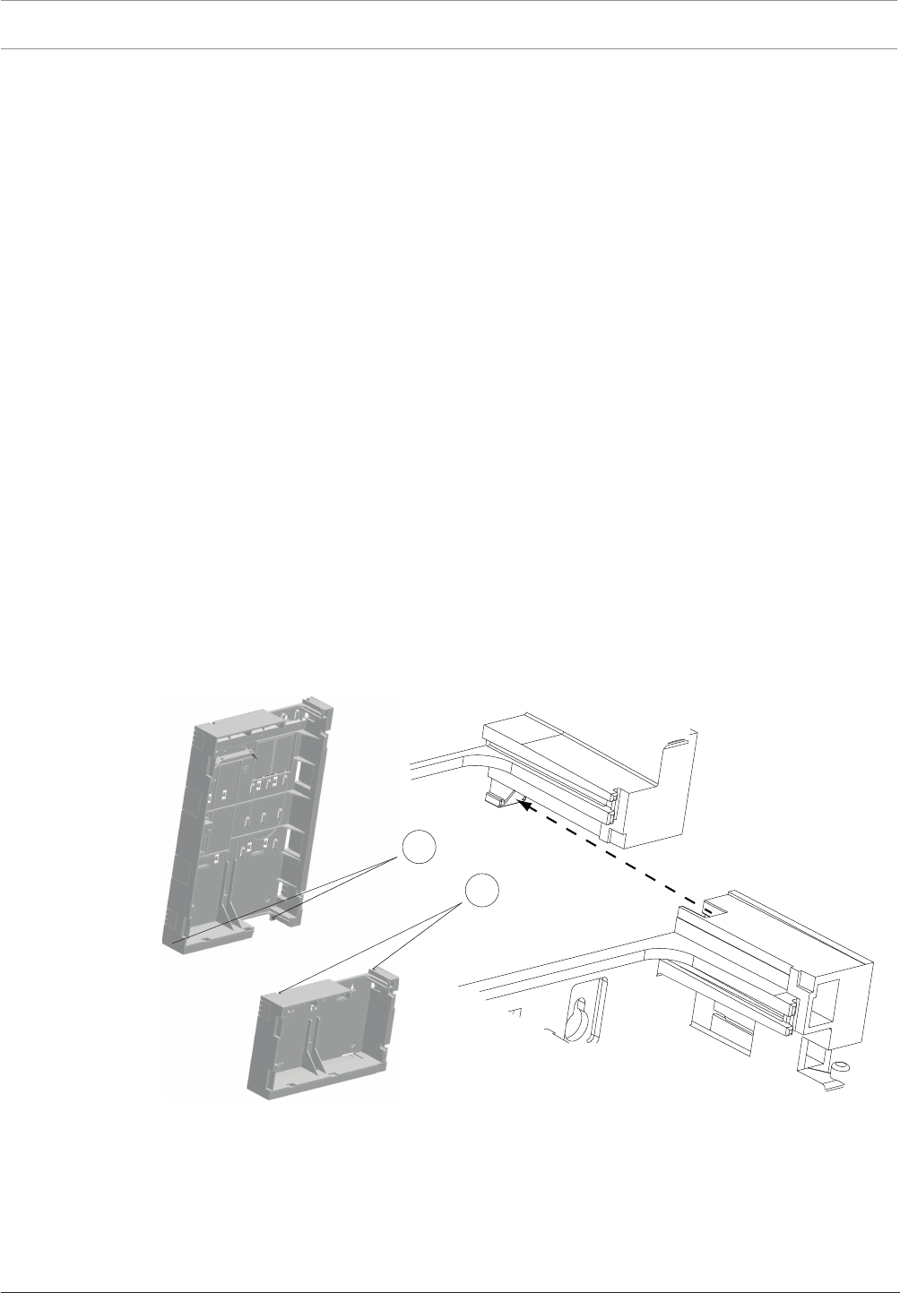
To install, proceed as follows:
1. Mark the 3 required holes on the wall as shown in the installation drawing.
2. At the marked points, drill holes approx. 55mm deep with an 8-mm drill. Insert a dowel
in each hole.
3. Screw the upper fixing screws to a distance of 5mm from the wall and fit the housing or
mounting frame.
4. Now fit the third fixing screw. This 'safety' screw prevents the housing from being pushed
up and off the top screws.
5. Then check the installation position and securely tighten all screws.
Installing Several Housings
It is possible to install several housings for frame mounting directly beneath each other by
connecting the frames to each other. The following instructions explain such an installation
using the example of the FBH0000A and FSH0000A mounting frames.
First, install the FBH0000A mounting frame as explained above (steps 1-5).
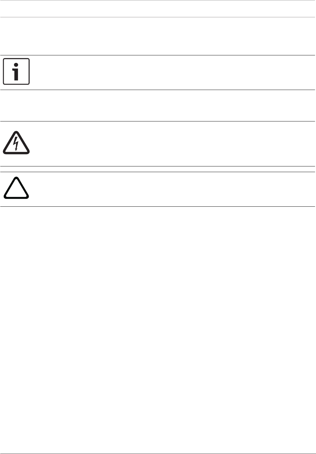
1. Push the grooves of the FSH 0000 A Mounting Frame (2) onto the guide rails of the
FBH0000A Mounting Frame (1).
1
2
FBH 0000 A
FSH 0000 A
2. Mark the 3 required holes on the wall as shown in the installation drawing for the
FSH0000A Mounting Frame (see ).
3. Remove the FSH0000A Mounting Frame.
4. At the marked points, drill holes approx. 55mm deep with an 8-mm drill. Insert a dowel
in each hole.
5. Refit the FSH0000A Mounting Frame, as described in step 1.
6. Screw the FSH0000A Mounting Frame tight.

Modular Fire Panel Installation | en 45
Bosch Sicherheitssysteme GmbH System Information 09.2017 | 11.3 | F.01U.028.089
4.3.1 Installation Instructions for Housing
All housings and housing components are supplied with installation instructions ex works.
You can also find the installation instructions at www.boschsecurity.com by searching for the
type designation of the product you want to install. The document numbers of the installation
instructions can be found in the footer on every page of the document.
The tables below show the instructions available.
Frame Mounting
Panel housings for frame installation Document number
CPH 0006 A Frame installation housing for 6 modules 4.998.154.002
MPH 0010 A Frame installation housing for 10 modules 4.998.154.003
Extension housings
EPH 0012 A Frame installation extension housing for 12 modules 4.998.154.005
PMF 0004 A Frame installation power supply housing F.01U.003.083
PSF 0002 A Frame installation power supply housing F.01U.003.082
USF 0000 A Universal frame installation extension housing F.01U.003.106
Mounting frames
FBH 0000 A Mounting frame, large 4.998.153.998
FHS 0000 A Mounting frame, large with distributor rail 4.998.154.018
FMH 0000 A Mounting frame, medium 4.998.153.999
FSH 0000 A Mounting frame, small 4.998.154.000
Installation kits
FRB 0019 A Installation kit for frame installation housing
CPH0006A, MPH0010A and EPH0012A
4.998.154.015
FRM 0019 A Installation kit for PMF0004A power supply housing 4.998.154.017
FRS 0019 A Installation kit for frame installation housing
PSF0002A and USF0000A
F.01U.003.352
Wall Mounting
Panel housings for wall mounting Document number
HCP 0006 A Modular panel housing for 6 modules 4.998.153.981
HBC 0010 A Modular panel housing for 10 modules 4.998.153.995
Extension housings
HBE 0012 A Wall mounting extension housing for 12 modules 4.998.153.996
PSB 0004 A Wall mounting power supply housing 4.998.154.010
PSS 0002 A Wall mounting power supply housing 4.998.154.009
DIB 0000 A Distribution box F.01U.003.105

46 en | Installation Modular Fire Panel
09.2017 | 11.3 | F.01U.028.089 System Information Bosch Sicherheitssysteme GmbH
Installation kit
FRK 0019 A Universal installation kit for all wall mounting housings F.01U.005.045
Front Doors
Type designation Description Document number
FDT 0000 A Front door, transparent, lock right side F.01U.003.101
FDT 0001 A Front door, transparent, large, lock right side F.01U.003.100
FDT 0002 A Front door, transparent, large, lock left side F.01U.003.104
FDT 0003 A Front door, transparent, lock left side F.01U.003.102
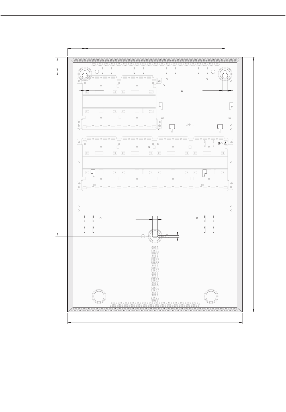
Modular Fire Panel Installation | en 47
Bosch Sicherheitssysteme GmbH System Information 09.2017 | 11.3 | F.01U.028.089
4.3.2 Installation Dimensions for Wall Mounting Housing
HCP0006A Modular Panel Housing for 6 Modules
45
904
440
836
83
6,5 12,5
350
12
5,6
Figure4.1: Housing: Installation dimensions - HCP0006A [inmm]
48 en | Installation Modular Fire Panel
09.2017 | 11.3 | F.01U.028.089 System Information Bosch Sicherheitssysteme GmbH
HBC0010A Modular Panel Housing for 10 Modules
45
906
440
0
48
83
6,5 12,5
350
12
5,6
Figure4.2: Installation dimensions - HBC0010A [inmm]
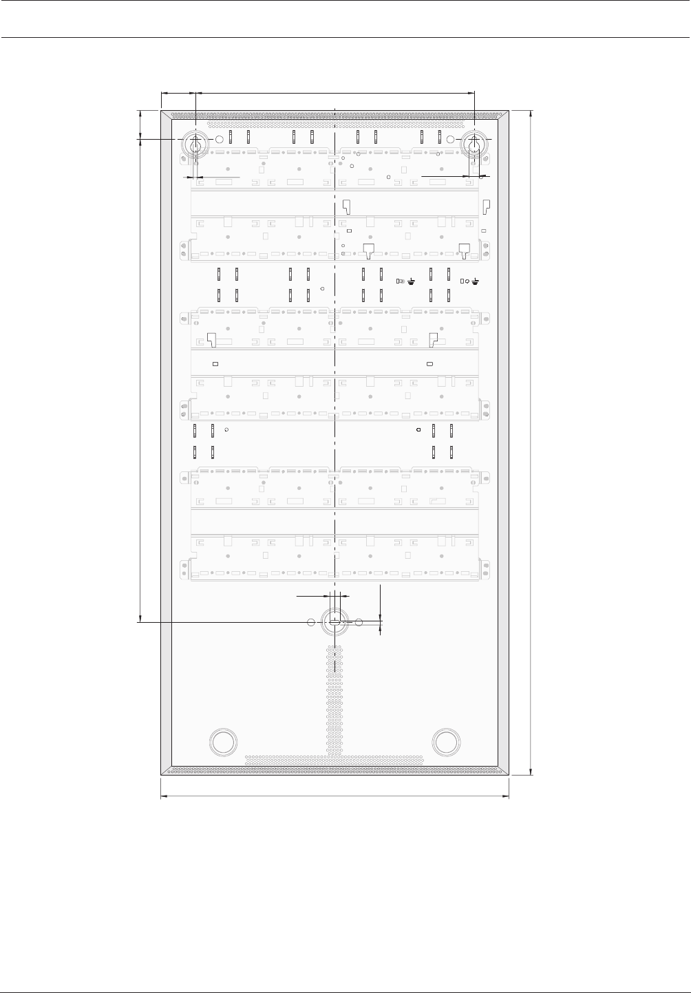
Modular Fire Panel Installation | en 49
Bosch Sicherheitssysteme GmbH System Information 09.2017 | 11.3 | F.01U.028.089
HBE0012A Modular Extension Housing for 12Modules
45
906
440
0
48
83
6,5 12,5
350
12
5,6
Figure4.3: Installation dimensions - HBE0012A [inmm]
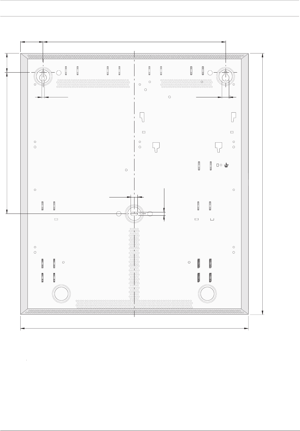
50 en | Installation Modular Fire Panel
09.2017 | 11.3 | F.01U.028.089 System Information Bosch Sicherheitssysteme GmbH
PSB0004A Power Supply Module, Wall Mounting
45
8
0
3
440
205
8
3
6,5 12,5
350
12
5
,6
Figure4.4: Installation dimensions - PSB0004A [inmm]

Modular Fire Panel Installation | en 51
Bosch Sicherheitssysteme GmbH System Information 09.2017 | 11.3 | F.01U.028.089
PSS0002A Power Supply Small/DIB0000A Distribution Box
45
712
440
762
8
3
6,5 12,5
350
12
5
,
6
Figure4.5: Installation dimensions - PSS0002A/DIB0000A [inmm]
Cable Bushings
Wall mounting housings have pre-punched cable bushings with the three most common
diameters (22mm, 35mm, 44mm).
Notice!
Carefully punch out the pre-punched hole for the cable entry and fit a suitable cable
grommet. When inserting the cable into the housing, pierce a hole in the grommet with a
pointed object, do not cut.
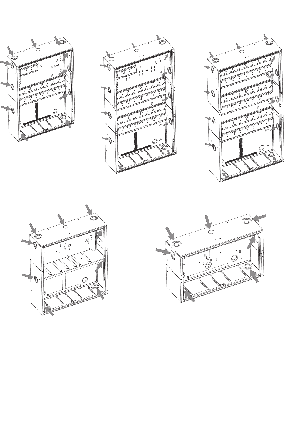
52 en | Installation Modular Fire Panel
09.2017 | 11.3 | F.01U.028.089 System Information Bosch Sicherheitssysteme GmbH
HCP 0006 A HBC 0010 A HBE 0012 A
PSB 0004 A PSS 0002 A
28.4
∅
28.4
∅
28.4
∅
28.4
∅
28.4
∅
Figure4.6: Wall mounting housing cable bushings
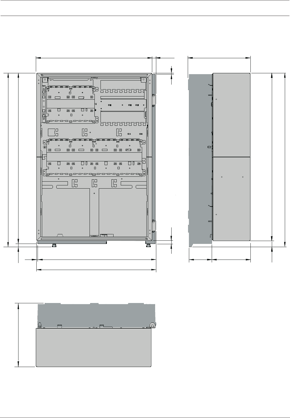
Modular Fire Panel Installation | en 53
Bosch Sicherheitssysteme GmbH System Information 09.2017 | 11.3 | F.01U.028.089
4.3.3 Installation Dimensions for Frame Installation Housing
Installation Dimensions for CPH0006A, EPH0012A and MPH0010A with FBH0000A or
FHS0000A Mounting Frames
236
638
663
651
663
12
3
236
440 15,5
145
452,5
455,5
391
13
25
Figure4.7: Housing:Installation dimensionsInstallation dimensions for CPH0006A, EPH0012A and MPH0010A [inmm]
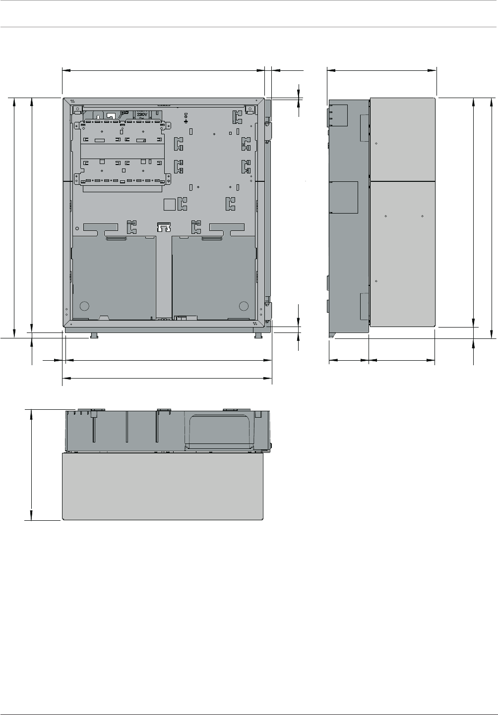
54 en | Installation Modular Fire Panel
09.2017 | 11.3 | F.01U.028.089 System Information Bosch Sicherheitssysteme GmbH
Installation Dimensions for PMF0004A with FMH0000A Mounting Frame
502
527
515
527
236
25
3
440 15,5
145
452,5
455,5
391
13
236 12
Figure4.8: Installation dimensions for PMF0004A [inmm]
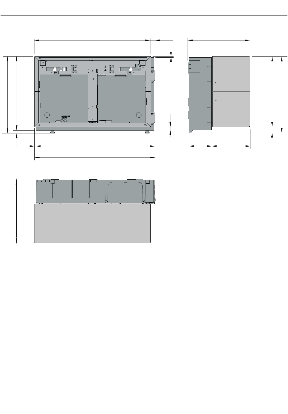
Modular Fire Panel Installation | en 55
Bosch Sicherheitssysteme GmbH System Information 09.2017 | 11.3 | F.01U.028.089
Installation Dimensions for PSF0002A and USF0000A with FSH0000A Mounting frame
267
292
280
292
3
440 15,5 236
13
25
145
452,5
455,5
391
236 12
Figure4.9: Installation dimensions for PSF0002A and USF0000A [inmm]
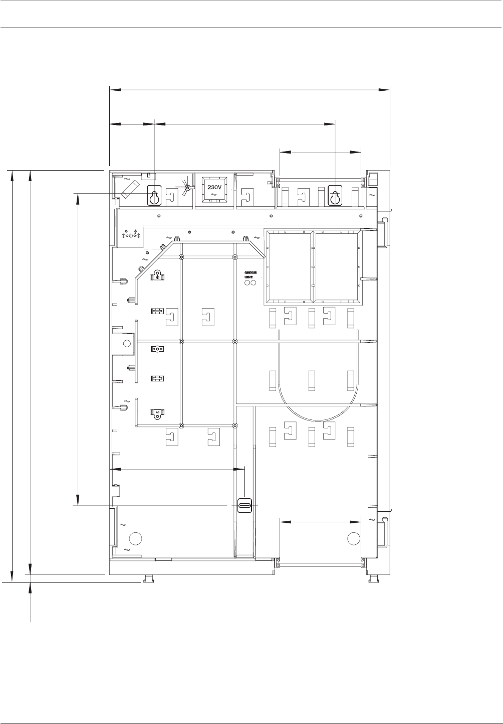
56 en | Installation Modular Fire Panel
09.2017 | 11.3 | F.01U.028.089 System Information Bosch Sicherheitssysteme GmbH
4.3.4 Installation Dimensions for Mounting Frames
FBH0000A/FHS0000A Mounting Frame Large
130
00
5
06
6
216
8
4
6
290 ± 0,5
450
130
71
2
1
Figure4.10: Mounting frame:Installation dimensionsInstallation dimensions - FBH0000A/FHS0000A [inmm]
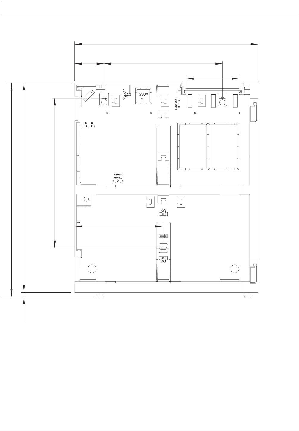
Modular Fire Panel Installation | en 57
Bosch Sicherheitssysteme GmbH System Information 09.2017 | 11.3 | F.01U.028.089
FMH0000A Mounting Frame Medium
290 ± 0,5
450
130
71
5,663
216
215
524
21
Figure4.11: Installation dimensions - FMH0000A [inmm]
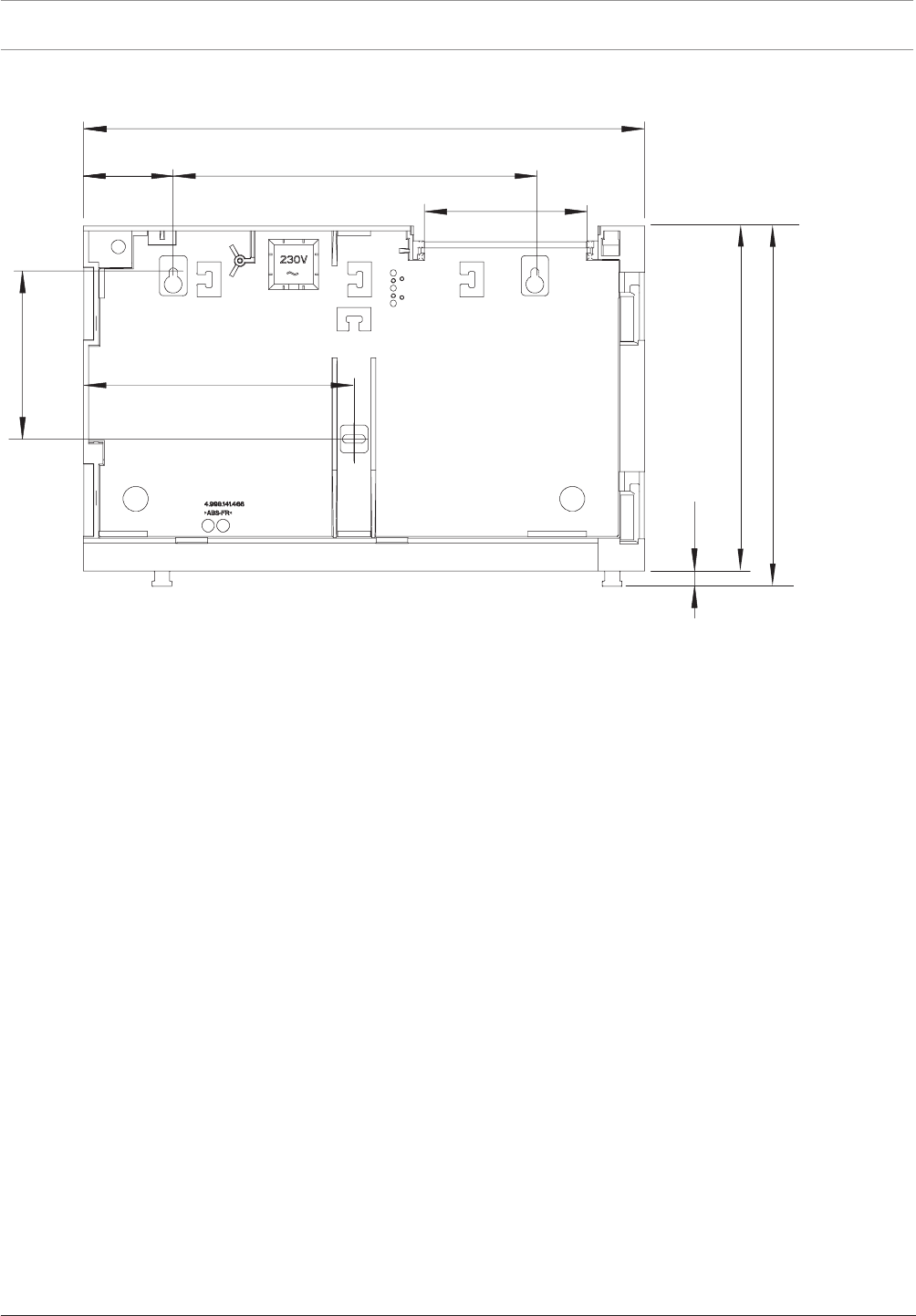
58 en | Installation Modular Fire Panel
09.2017 | 11.3 | F.01U.028.089 System Information Bosch Sicherheitssysteme GmbH
FSH0000A Mounting Frame Small
290 ± 0,5
450
130
71
4
31
216
772
289
21
Figure4.12: Installation dimensions - FSH0000A [inmm]
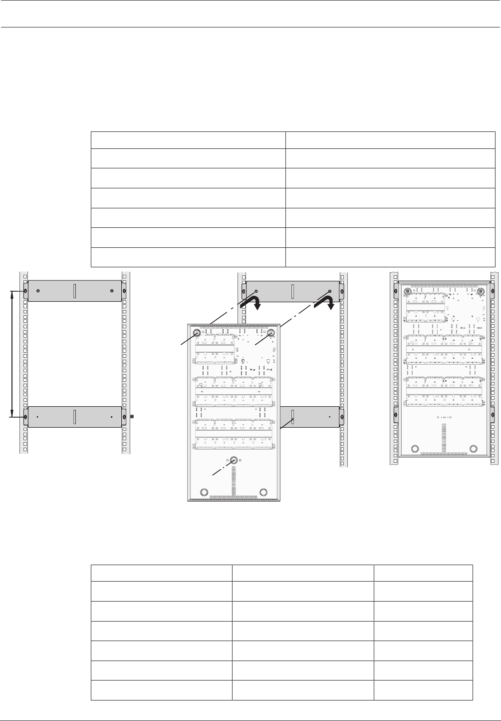
Modular Fire Panel Installation | en 59
Bosch Sicherheitssysteme GmbH System Information 09.2017 | 11.3 | F.01U.028.089
4.3.5 Installation Kits for 48cm (19”) Racks
FRK0019A Rack Installation Kit for All Wall Mounting Housings
The FRK 0019 A Rack Installation Kit is used to install wall mounting housings in 48cm (19'')
racks.
The two mounting brackets in the universal installation kit are fitted at distanceH (see ). The
dimensions of H for the different wall mounting housings can be found in the table below:
Housing H
PSS 0002 A 217mm
DIB 0000 A 217mm
PSB 0004 A 308mm
HCP 0006 A 409mm
HBC 0010 A 609mm
HBE 0012 A 609mm
H
Figure4.13: FRK0019A housing installation
Installation Kits for Frame Installation Housings
Special installation kits are available for installing frame installation housings in 48 cm (19'')
racks:
Housing type Installation kit Height unit
CPH 0006 A FRB 0019 A 15
MPH 0010 A FRB 0019 A 15
EPH 0012 A FRB 0019 A 15
PMF 0004 A FRM 0019 A 12
PSF 0002 A FRS 0019 A 6
USF 0000 A FRS 0019 A 6
No mounting frame is required when using the 48cm (19'') installation kits.
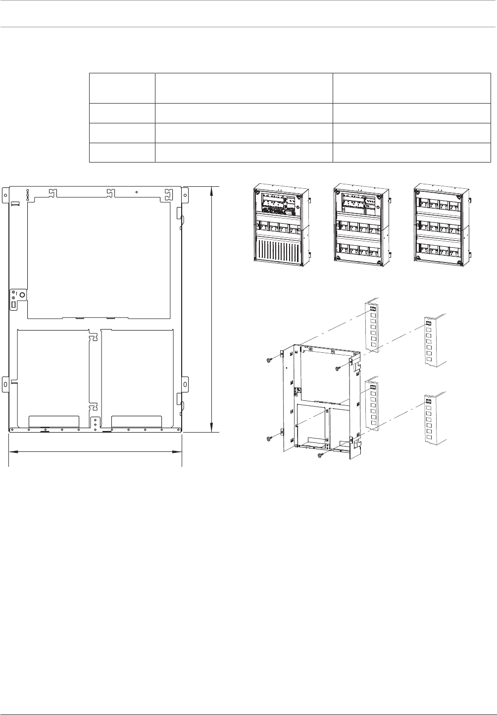
60 en | Installation Modular Fire Panel
09.2017 | 11.3 | F.01U.028.089 System Information Bosch Sicherheitssysteme GmbH
The table below shows the space required for the different frame installation housings when
using the installation kits for 48cm (19'') racks.
Installation
kit
Housing types Space required (H x B x T)
FRB 0019 A CPH 0006 A, MPH 0010 A, EPH 0012 A 638 x 449 x 233.5mm
FRM 0019 A PMF 0004 A 502 x 449 x 233.5mm
FRS 0019 A PSF 0002 A, USF 0000 A 267 x 449 x 233.5mm
FRB0019A Rack Installation Kit, Large
636
449
Figure4.14: FRB0019A installation kit for CPH0006A, MPH0010A, EPH0012A [installation dimensions inmm]
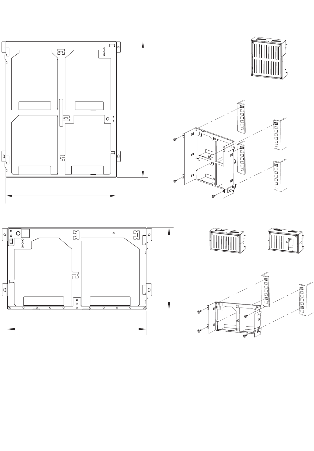
Modular Fire Panel Installation | en 61
Bosch Sicherheitssysteme GmbH System Information 09.2017 | 11.3 | F.01U.028.089
FRM0019A Rack Installation Kit, Medium
449
500
Figure4.15: FRM0019A installation kit for PMF0004A [installation dimensions inmm]
FRS0019A Rack Installation Kit, Small
265
449
Figure4.16: FRS0019A installation kit for PSF0002A, USF0000A [installation dimensions inmm]
The FRS0019A installation kit is also used for the THP2020A Thermal Printer.
4.4 Accessories for Housing
4.4.1 RLE0000A Junction Board
The RLE0000A Junction Board is designed for installation in the CPH 0006 and MPH 0010 A
frame installation housings.
Junction boards receive the cables coming from outside and allow clear onward transmission
to the individual modules.
The RLE0000A Junction Board is also required to connect the AT3000 transmission unit.
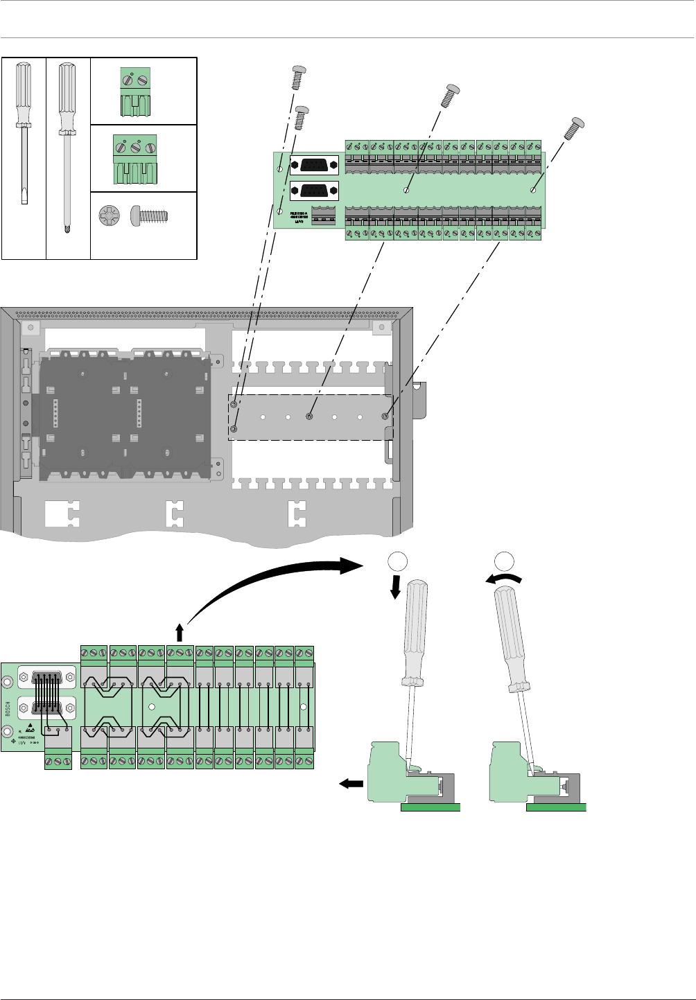
62 en | Installation Modular Fire Panel
09.2017 | 11.3 | F.01U.028.089 System Information Bosch Sicherheitssysteme GmbH
x
2
1
RLE 0000 A
4x
9x
12x
M3 x 10PZ3
PZ3
Figure4.17: RLE0000A installation
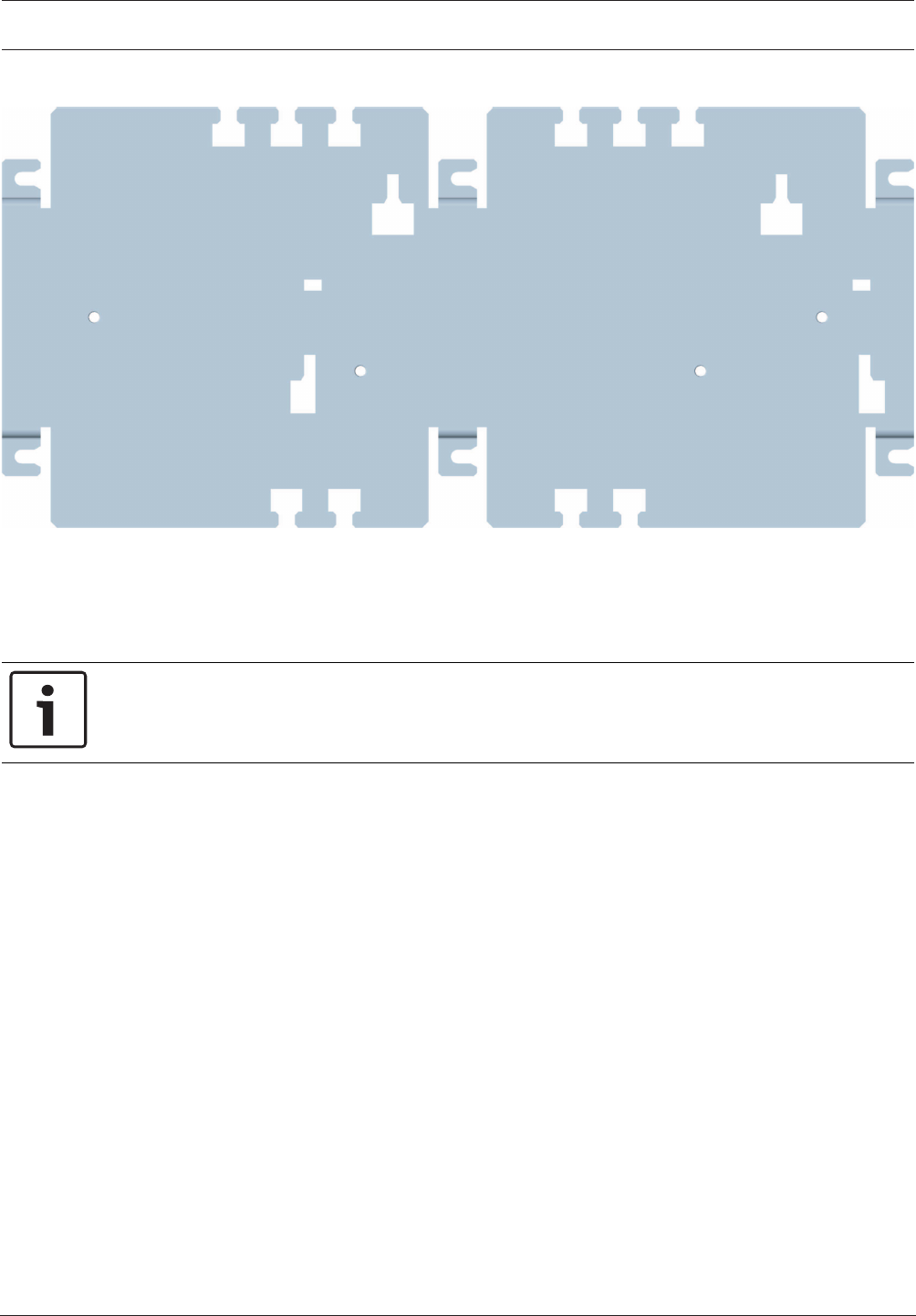
Modular Fire Panel Installation | en 63
Bosch Sicherheitssysteme GmbH System Information 09.2017 | 11.3 | F.01U.028.089
4.4.2 HMP0003A Mounting Plate for Mounting Frame
Figure4.18: HMP0003A Mounting Plate for Mounting Frame
The HMP0003A Mounting Plate is used in both the large FBH0000A and FHS0000A
mounting frames.
The mounting plate is required to install interface modules, external device controllers, relays
and other components. It can be fitted with a distributor rail.
Notice!
The distributor rail is not included in the scope of delivery for the HMP0003A Mounting
Plate.
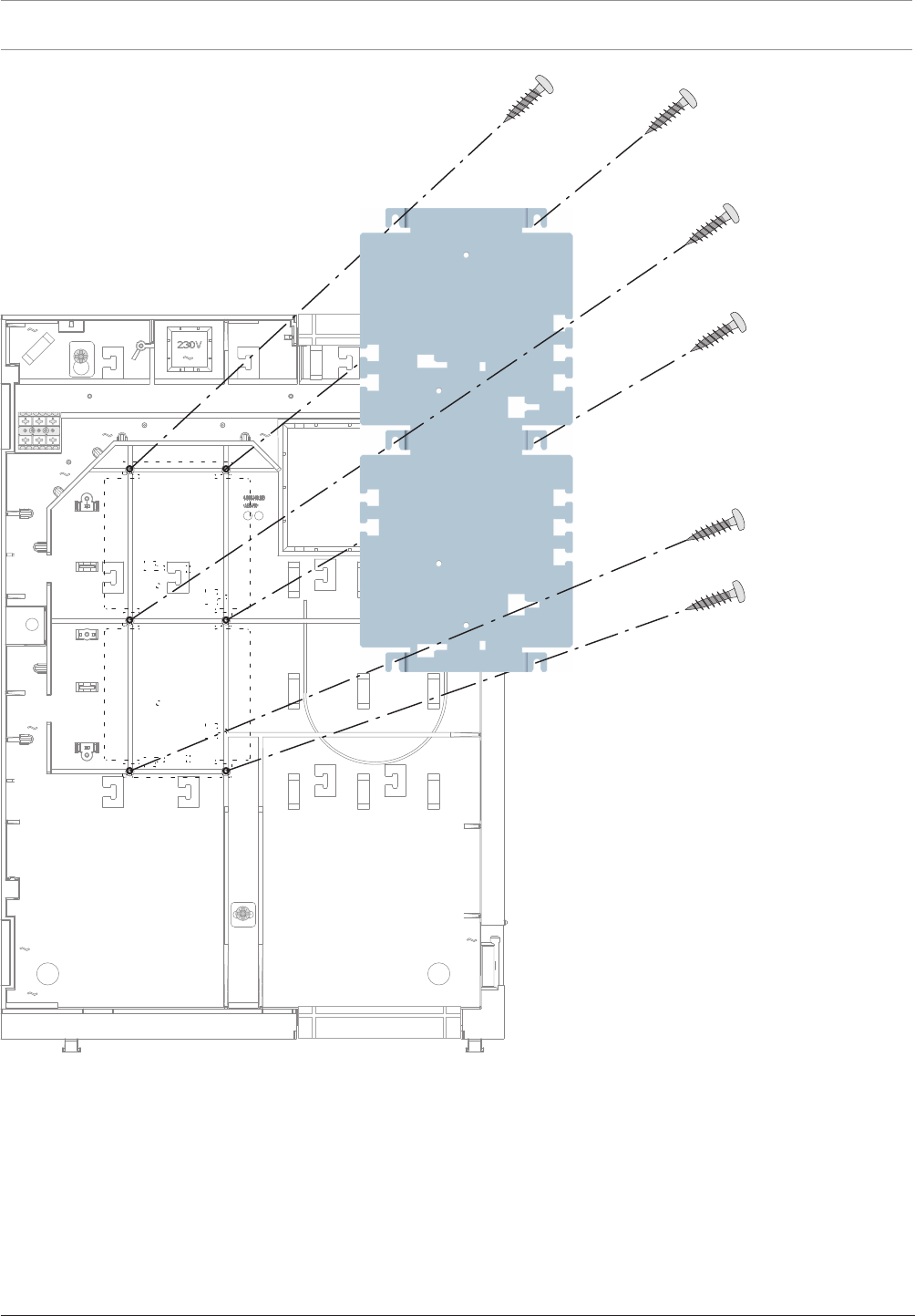
64 en | Installation Modular Fire Panel
09.2017 | 11.3 | F.01U.028.089 System Information Bosch Sicherheitssysteme GmbH
Figure4.19: HMP0003A installation
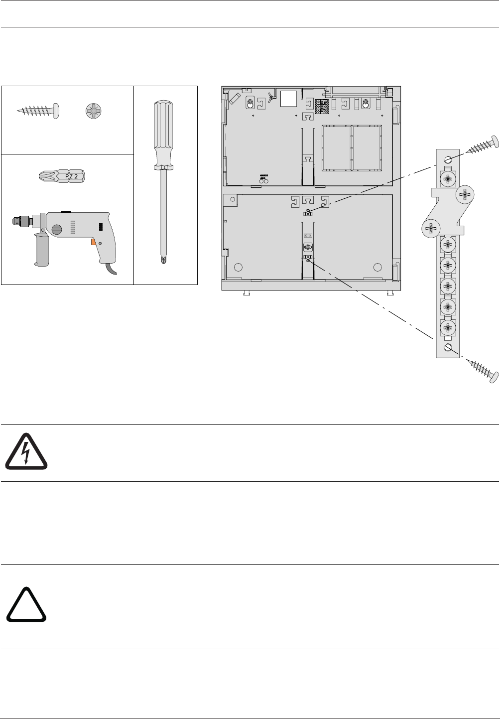
Modular Fire Panel Installation | en 65
Bosch Sicherheitssysteme GmbH System Information 09.2017 | 11.3 | F.01U.028.089
4.4.3 FPO-5000-EB Earth Bar
The FPO-5000‑EB Earth Bar is inserted in the FMH0000A Mounting Frame Medium in a
prefabricated bracket. It allows star grounding of a centrally positioned extension housing.
FPO-5000-EB
FMH 0000 A
∅ 4 x 12 mm PZ2
PZ2
2x
PZ2
Figure4.20: FPO‑5000‑EB installation
4.5 Power Supply Brackets
Danger!
The device contains live components.
Touching live components entails a risk of death or serious injury.
Disconnect the power supply before all installation work.
The power supply brackets are designed for installation in wall mounting housings and can
hold a UPS2416A Universal Power Supply. This is ready for immediate operation via the pre-
wired plug connection.
The brackets are made of fiberglass-reinforced plastic and have a fuse (T10A) and a
temperature sensor, which is positioned between the batteries.
!
Warning!
There is a risk of injury if the temperature sensor is not positioned between the batteries.
The temperature sensor is supplied with the power supply bracket and protects the batteries
against overheating. If the sensor is not positioned correctly, the batteries can overheat and
explode.
Position the temperature sensor between the batteries.
Power supply brackets are available in the FPO‑5000‑PSB‑CH (see FPO‑5000‑PSB‑CH Power
Supply Bracket, page 67) and FPO‑5000‑PSB1 (see FPO-5000-PSB1 Power Supply Bracket,
page 71) versions.
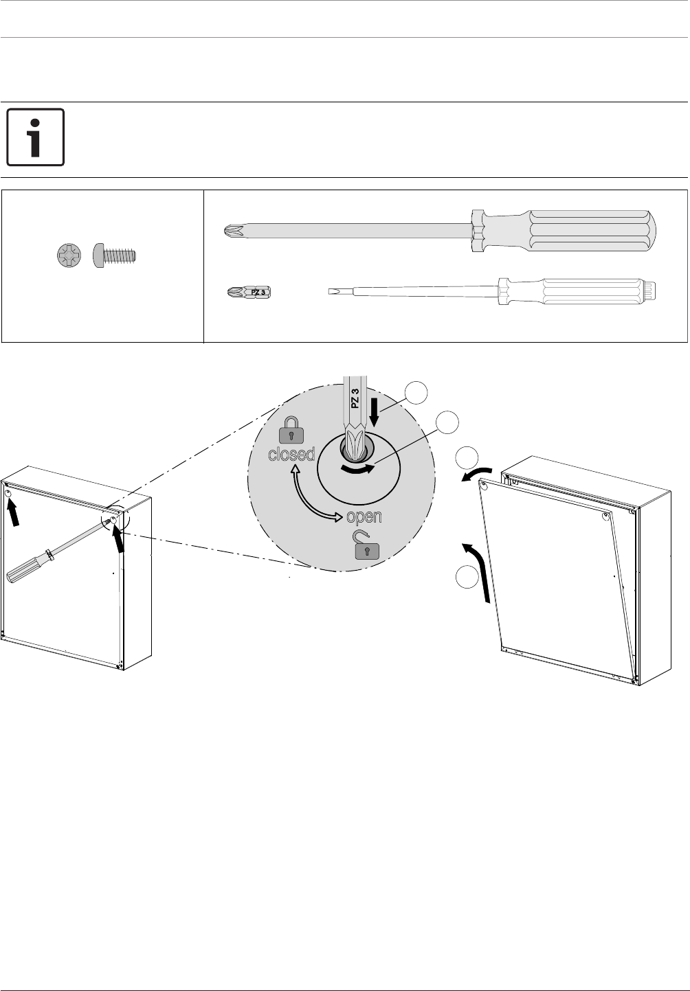
66 en | Installation Modular Fire Panel
09.2017 | 11.3 | F.01U.028.089 System Information Bosch Sicherheitssysteme GmbH
All frame installation housings designed for a power supply bracket are supplied with one of
these brackets, which is fitted ex works.
Notice!
A maximum of one power supply bracket and one power supply can be installed in the power
supply housing.
2
4
3
1
PZ3
3x
M4 x 12 mm
Figure4.21: FPO‑5000‑PSB‑CH/FPO‑5000‑PSB1 installation (1-4)
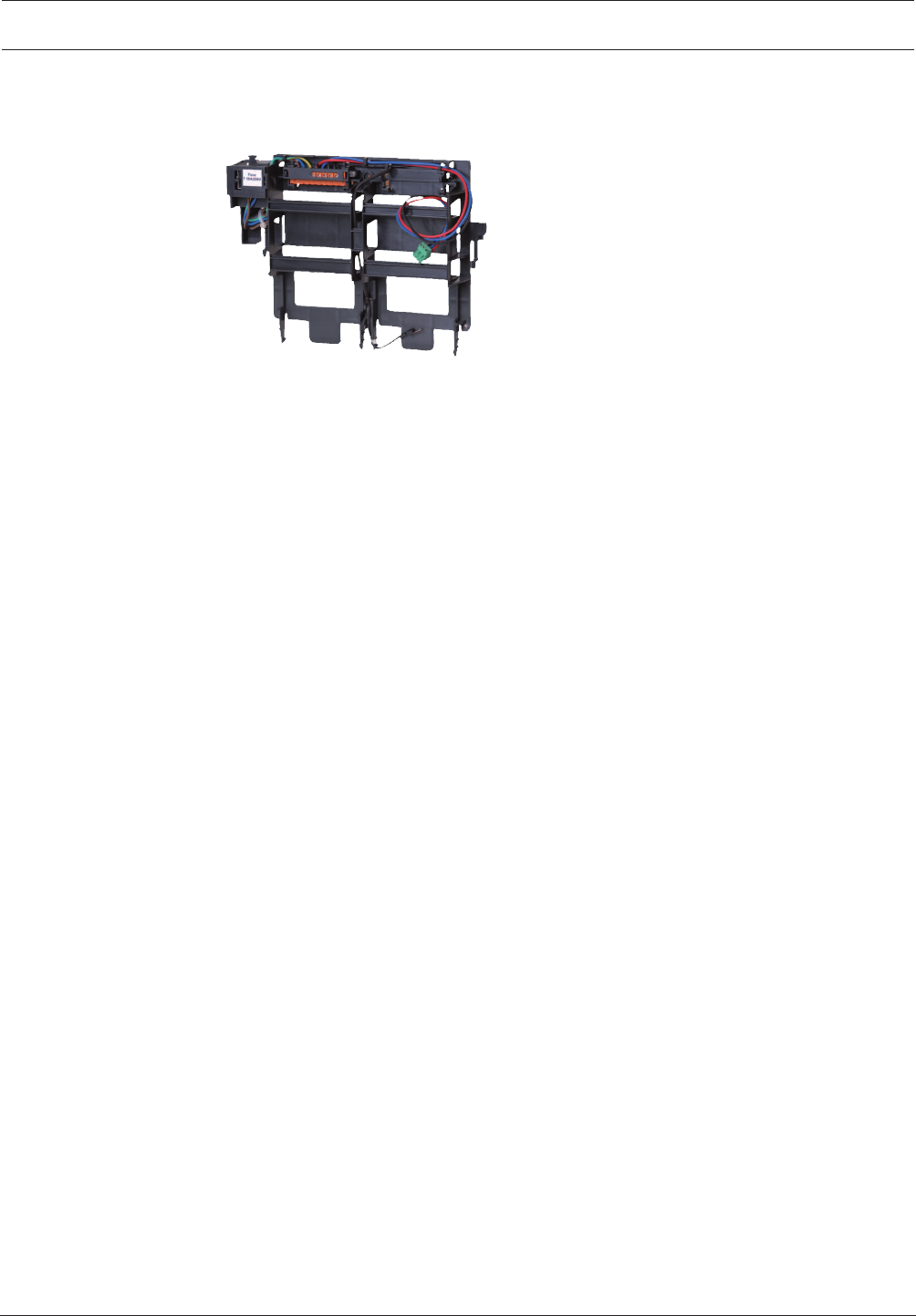
Modular Fire Panel Installation | en 67
Bosch Sicherheitssysteme GmbH System Information 09.2017 | 11.3 | F.01U.028.089
4.5.1 FPO‑5000‑PSB‑CH Power Supply Bracket
Figure4.22: FPO‑5000‑PSB‑CH Power Supply Bracket
The FPO‑5000‑PSB‑CH Power Supply Bracket is used in the HCP0006A, HBC0010A and
HBE0012A wall mounting housings.
The technical data can be found in FPO‑5000‑PSB1/FPO‑5000‑PSB‑CH Power Supply Brackets,
page 148.
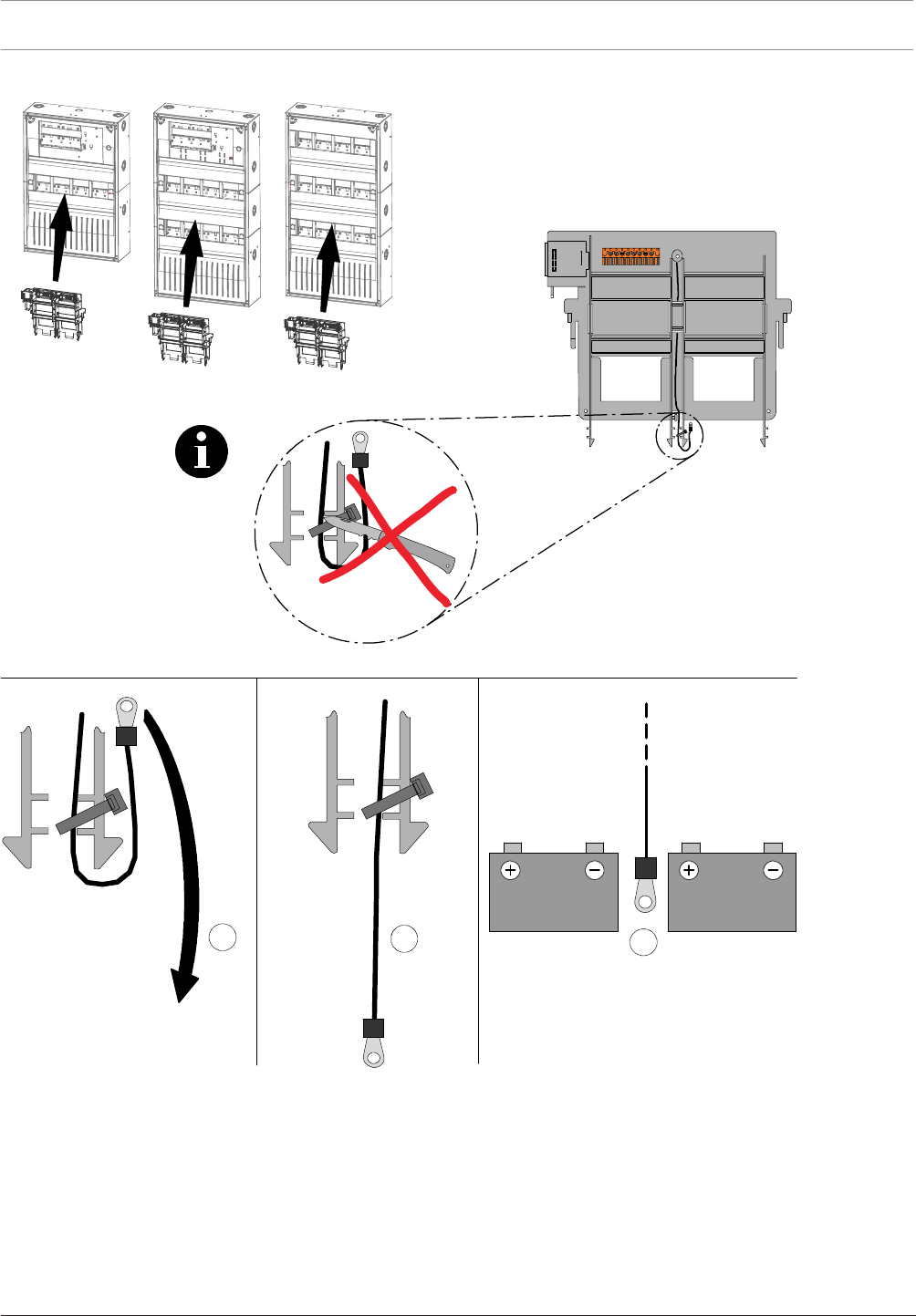
68 en | Installation Modular Fire Panel
09.2017 | 11.3 | F.01U.028.089 System Information Bosch Sicherheitssysteme GmbH
HCP0006 A HBC 0010 A HBE 0012 A
ABC
Figure4.23: FPO‑5000‑PSB‑CH housing compatibility and installation of temperature sensor
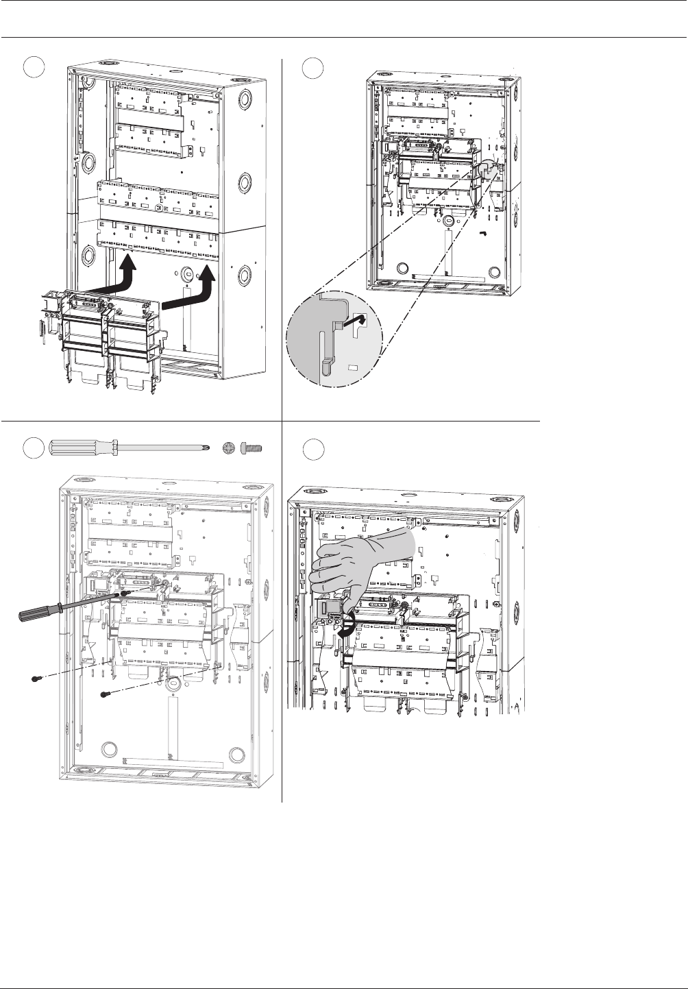
Modular Fire Panel Installation | en 69
Bosch Sicherheitssysteme GmbH System Information 09.2017 | 11.3 | F.01U.028.089
56
73x
M4 x 12 mm
8
Figure4.24: FPO‑5000‑PSB‑CH installation (5-8)
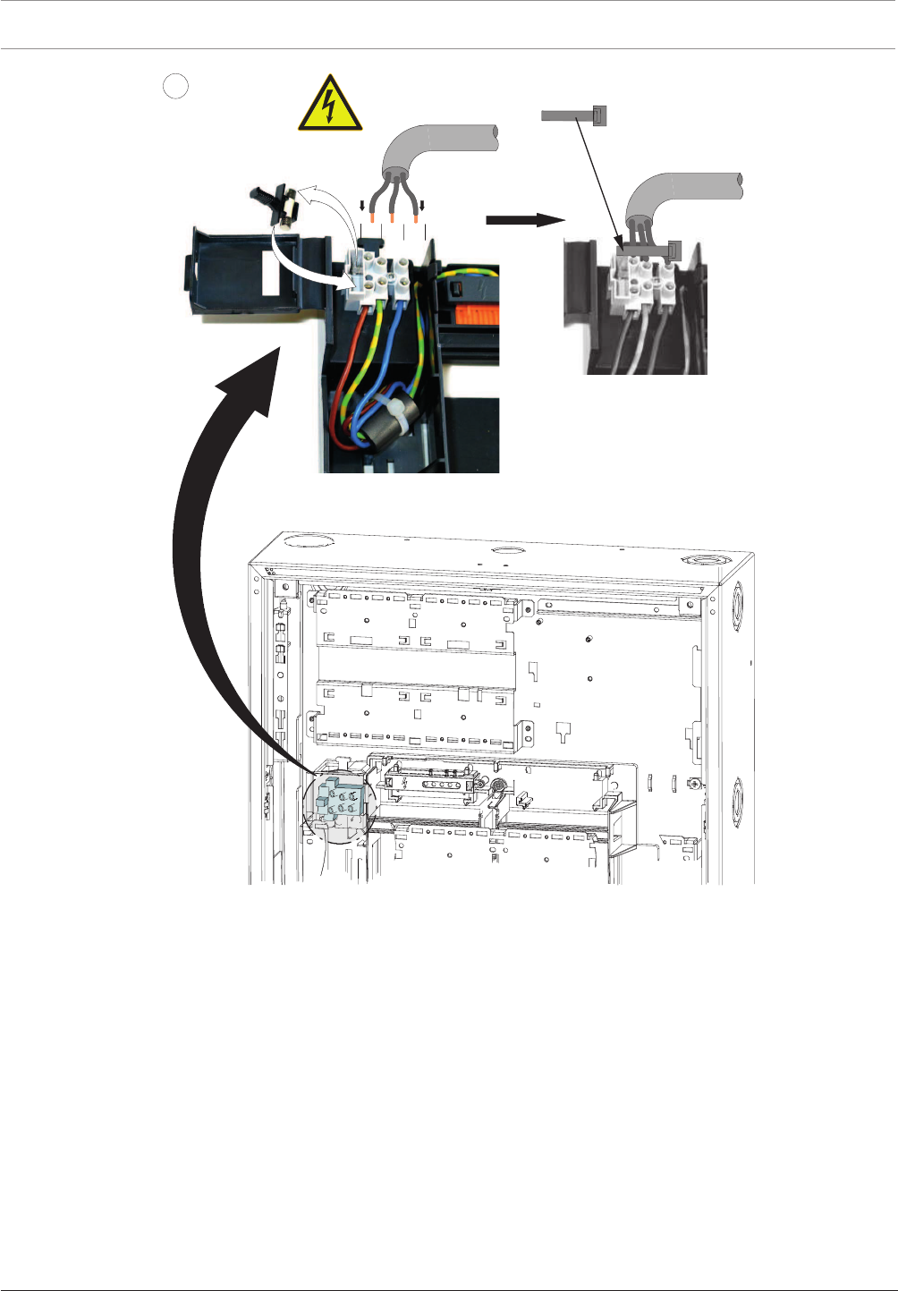
70 en | Installation Modular Fire Panel
09.2017 | 11.3 | F.01U.028.089 System Information Bosch Sicherheitssysteme GmbH
50 - 60 Hz
9
T 10 A / 250 V
100 - 240 V AC
L1 G N
Figure4.25: FPO‑5000‑PSB‑CH installation (9)
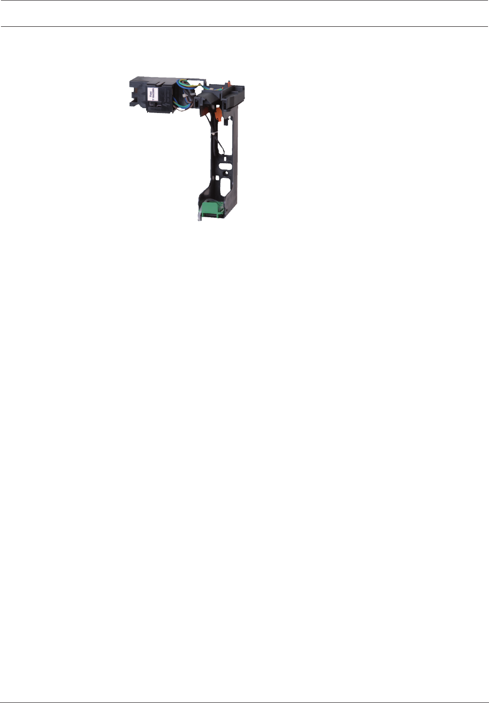
Modular Fire Panel Installation | en 71
Bosch Sicherheitssysteme GmbH System Information 09.2017 | 11.3 | F.01U.028.089
4.5.2 FPO-5000-PSB1 Power Supply Bracket
Figure4.26: FPO‑5000‑PSB1 Power Supply Bracket
The FPO‑5000‑PSB1 Power Supply Bracket is used in the PSS0002A and PSB0004A power
supply housings.
It is installed in a central position between two batteries.
The technical data can be found in FPO‑5000‑PSB1/FPO‑5000‑PSB‑CH Power Supply Brackets,
page 148.
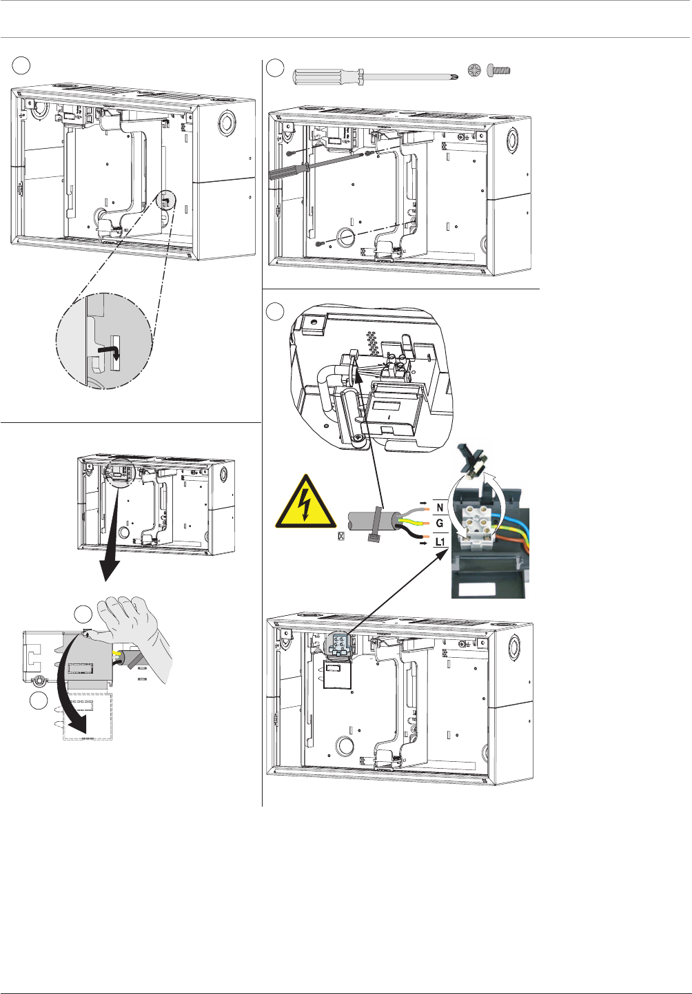
72 en | Installation Modular Fire Panel
09.2017 | 11.3 | F.01U.028.089 System Information Bosch Sicherheitssysteme GmbH
53x
M4 x 12 mm
6
7
8
100 -- 240 V
50 -- 60 Hz
9
Figure4.27: FPO‑5000‑PSB1 installation (5-9)
4.6 UPS2416A Universal Power Supply 24V/6A
The UPS2416A is a plug-and-play switching power supply that provides the power for the
FPA‑5000 Fire Panel. It is inserted into a power supply bracket and is then ready to use
immediately.
The power supply unit is protected against pole reversal and overvoltage. A green LED on the
power supply unit itself indicates that it is functioning.
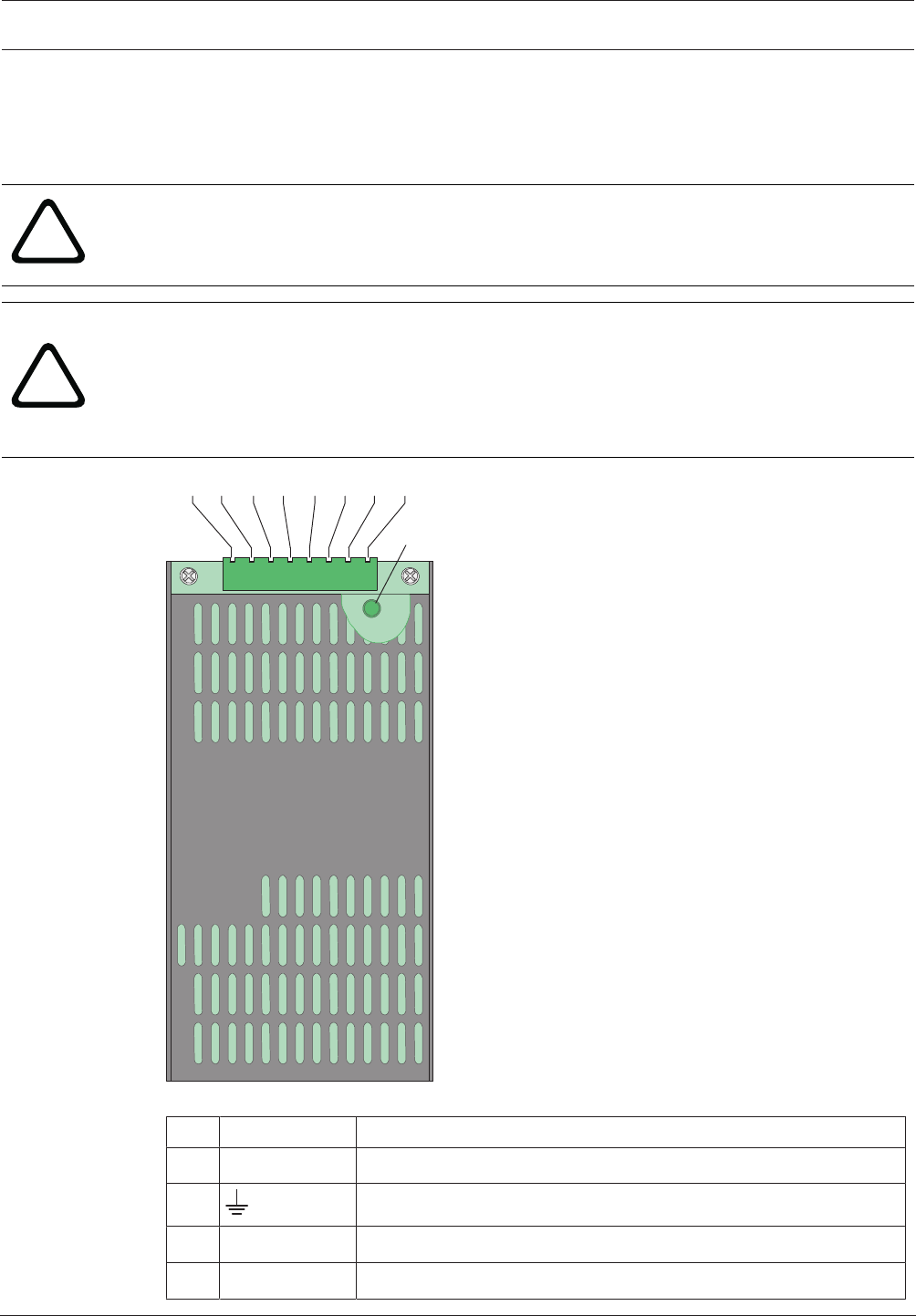
Modular Fire Panel Installation | en 73
Bosch Sicherheitssysteme GmbH System Information 09.2017 | 11.3 | F.01U.028.089
The temperature-dependent output voltage is monitored and regulated by the BCMBattery
Controller Module.
The output voltage is monitored and regulated by a temperature sensor. If there is a fault, the
FAULT output drops to 0V.
!
Warning!
The power supply unit may only be used in the specially designed brackets and in a fireproof
cover (such as a panel housing).
!
Warning!
There is a risk of injury if the temperature sensor is not positioned between the batteries.
The temperature sensor is supplied with the power supply bracket and protects the batteries
against overheating. If the sensor is not positioned correctly, the batteries can overheat and
explode.
Position the temperature sensor between the batteries.
12345678
LED
1 8
Figure4.28: UPS2416A Universal Power Supply 24V/6A
Pos. Labeling Connection
1 - 2 ACL | ACN Mains supply
3 Protective ground
4 - 5 DC+ | DC- 26.76VDC output plus/0VDC output minus
6 FAULT Mains fault output

74 en | Installation Modular Fire Panel
09.2017 | 11.3 | F.01U.028.089 System Information Bosch Sicherheitssysteme GmbH
Pos. Labeling Connection
7 - 8 RTH+ | RTH- Temperature sensor plus/minus
The universal power supply is used with the FPO-5000-PSB1 and FPO-5000-PSB‑CH Power
Supply Brackets. These power supply brackets can be used in the following wall mounting
housings:
Power supply bracket Housing
FPO-5000-PSB1 PSS 0002 A, PSB 0004 A
FPO-5000-PSB‑CH HCP 0006 A, HBC 0010 A, HBE 0012 A
Information on power supply brackets can be found in Power Supply Brackets, page 65.
The technical data can be found in UPS2416A Universal Power Supply 24V/6A, page 148.
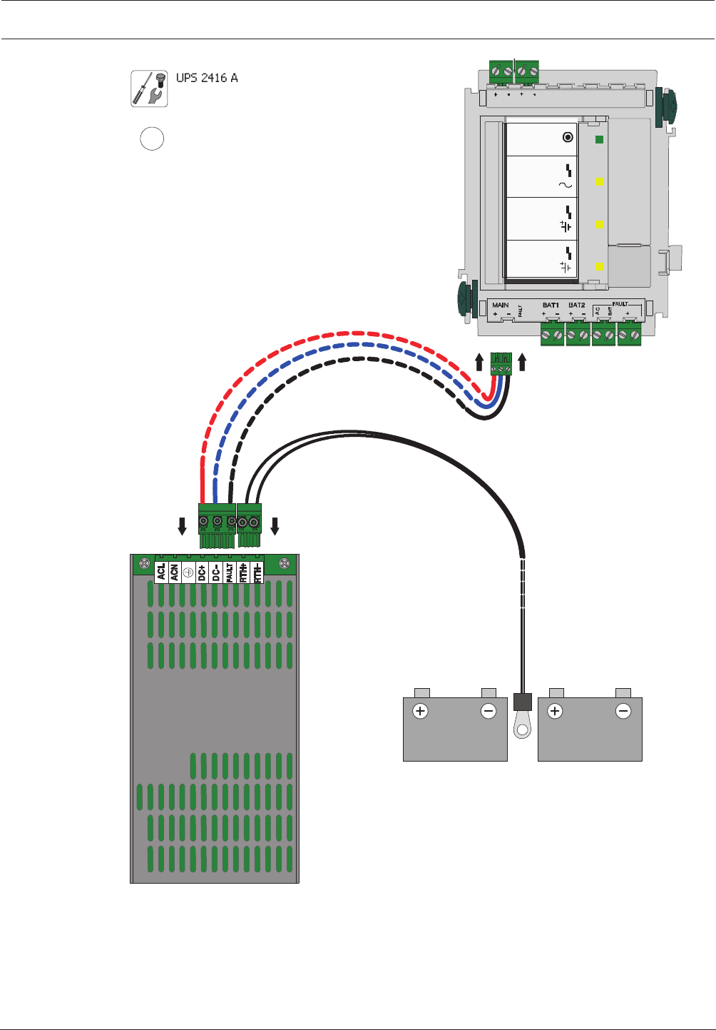
Modular Fire Panel Installation | en 75
Bosch Sicherheitssysteme GmbH System Information 09.2017 | 11.3 | F.01U.028.089
BCM-0000-B
UPS 2416 A
1
FPO-5000-PSB1
MAIN POWER
MAIN POWER
TROUBLE
BATTERY 1
BATTERY 2
TROUBLE
TROUBLE
24 V 24 V
Σ
24 V
B
-
0
0
0
0
-
MCB
Figure4.29: Installation of UPS2416A in FPO‑5000‑PSB1 (1)
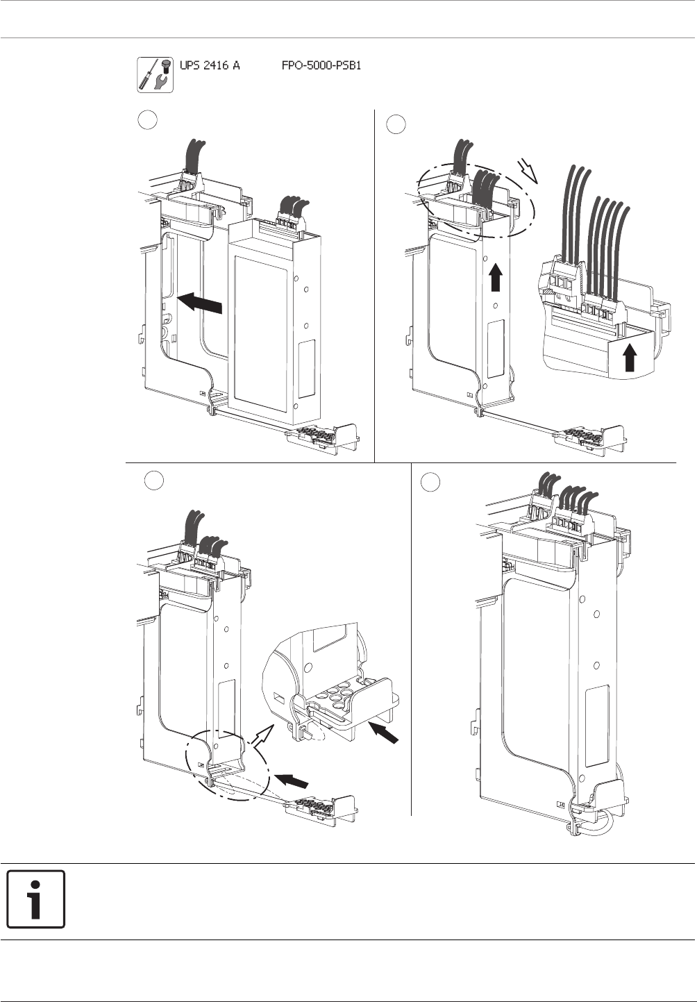
76 en | Installation Modular Fire Panel
09.2017 | 11.3 | F.01U.028.089 System Information Bosch Sicherheitssysteme GmbH
23
5
4
Figure4.30: Installation of UPS2416A in FPO‑5000‑PSB1 (2-5)
Notice!
Only one power supply unit can be installed in the FPO-5000-PSB‑CH Power Supply Bracket
(see figure).
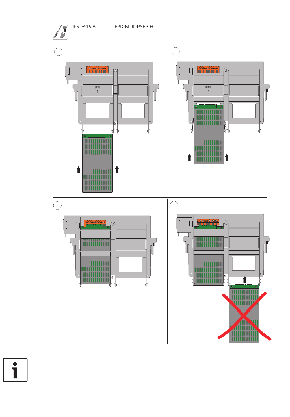
Modular Fire Panel Installation | en 77
Bosch Sicherheitssysteme GmbH System Information 09.2017 | 11.3 | F.01U.028.089
3
2
1
4
Figure4.31: Installation of UPS2416A in FPO-5000‑PSB‑CH (1-4)
Notice!
Each power supply unit and each housing comes with a self-adhesive product label. Attach
the sticker to the outside of the housing (see figure).
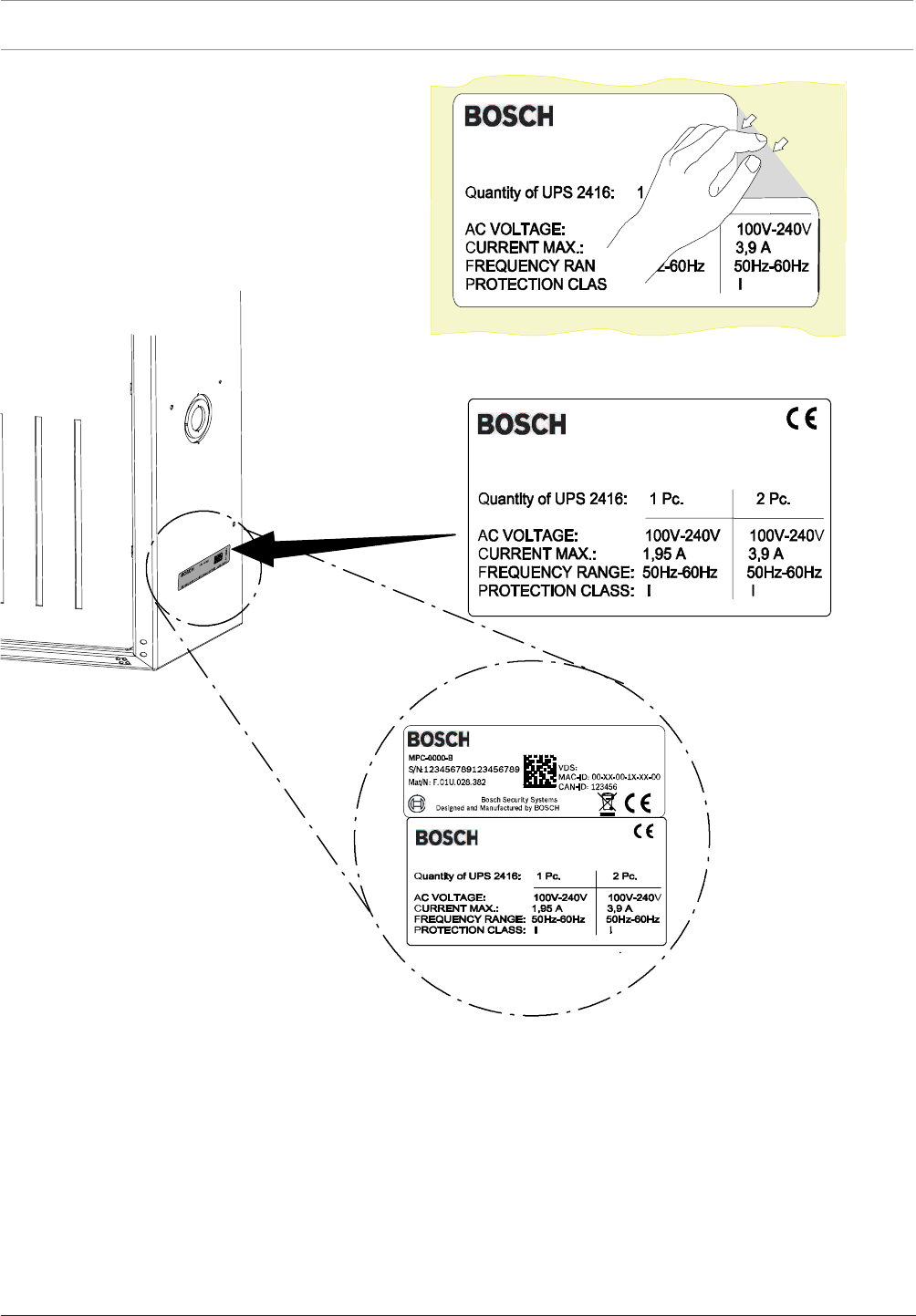
78 en | Installation Modular Fire Panel
09.2017 | 11.3 | F.01U.028.089 System Information Bosch Sicherheitssysteme GmbH
Figure4.32: Attaching the stickers
4.7 Panel Rails
4.7.1 PRS-0002-C Panel Rail Short for 2 Modules
The PRS-0002-C Panel Rail Short has two module slots and is supplied with 24 V DC by the
BCM-0000-B. An integrated voltage converter then generates the 5 V DC operating voltage
required by the modules. Due to its concealed position behind the operating and display
panel, the PRS-0002-C Panel Rail Short is intended for installation of the following modules
without operating and display elements:
– BCM-0000-B Battery Controller Module
– IOS 0020 A and IOS 0232 A Communication Modules
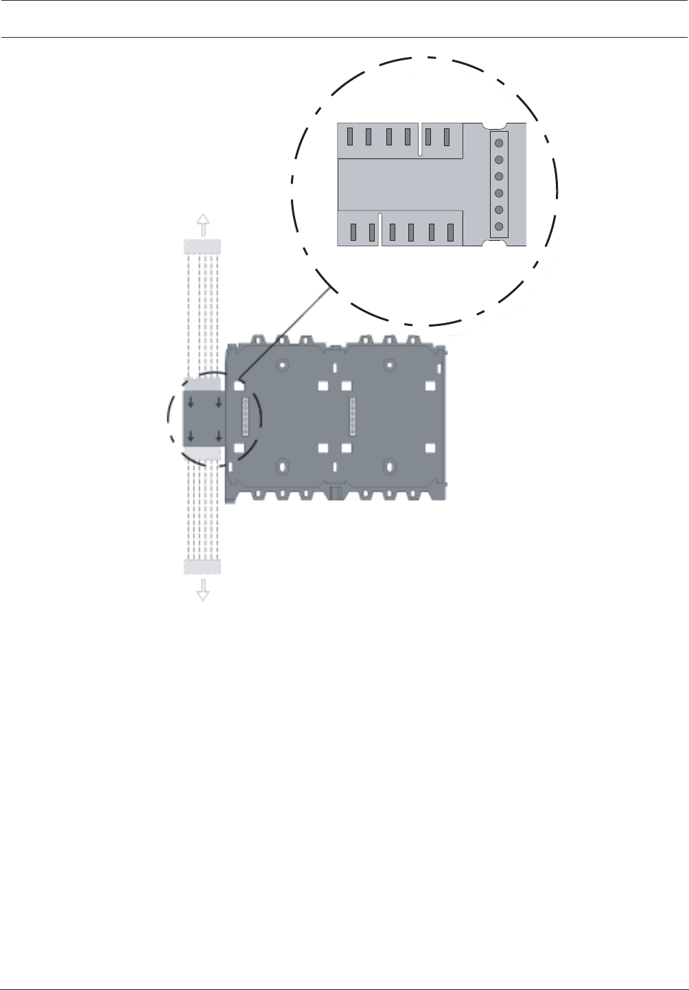
Modular Fire Panel Installation | en 79
Bosch Sicherheitssysteme GmbH System Information 09.2017 | 11.3 | F.01U.028.089
CANH
CANL
+24V
GND
24VMID
MID
CANH
CANL
+24V
GND
MID
CANH
CANL
+24V
GND
+5V
MID
PRD 0004 A
MPC
Figure4.33: PRS-0002-C connections
The technical data can be found in PRS-0002-C Panel Rail Short for 2 Modules, page 146.
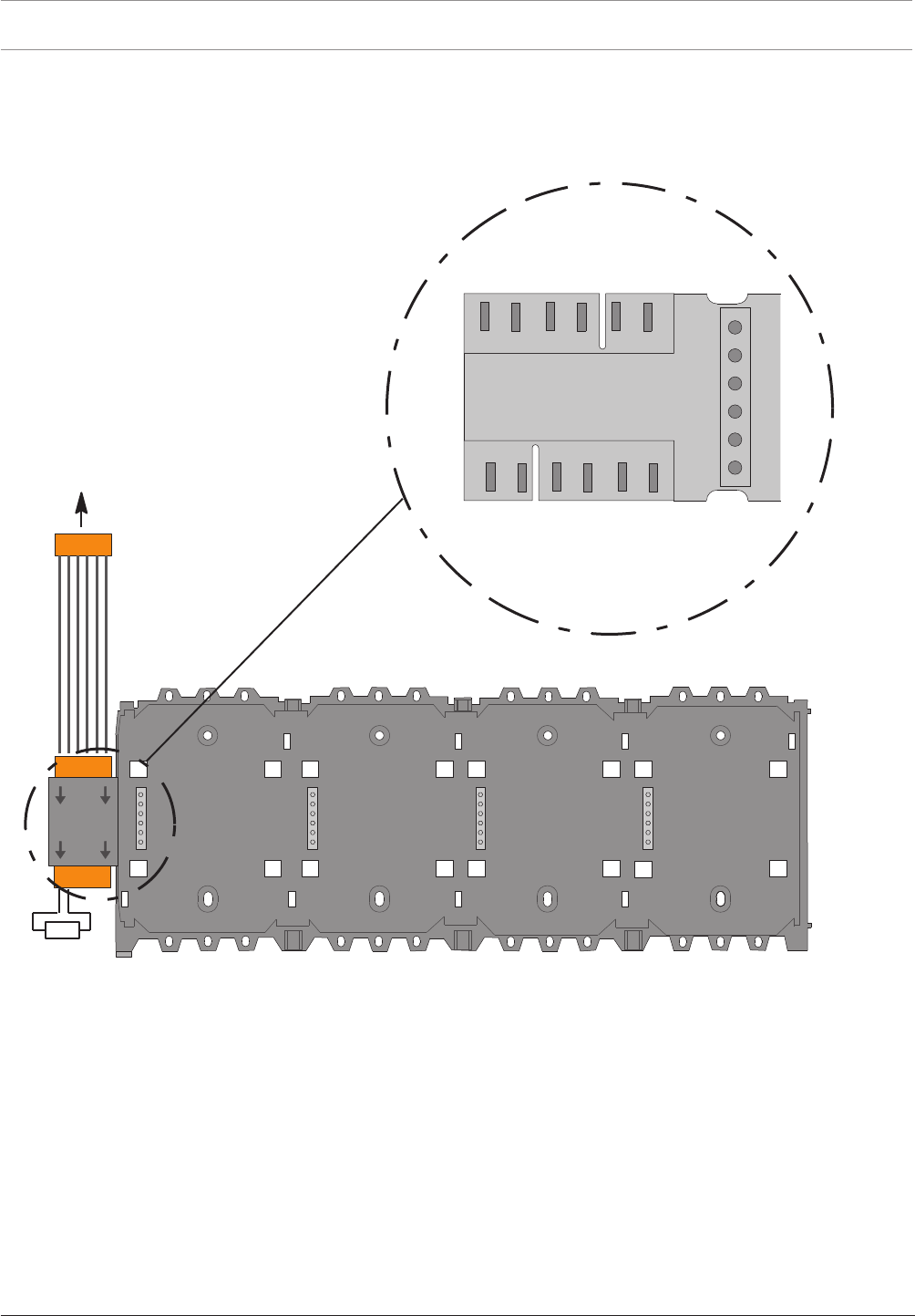
80 en | Installation Modular Fire Panel
09.2017 | 11.3 | F.01U.028.089 System Information Bosch Sicherheitssysteme GmbH
4.7.2 PRD0004A Panel Rail Long for 4 Modules
The PRD0004A Panel Rail Long has four module slots and is supplied with 24VDC by the
BCM. An integrated voltage converter then generates the 5VDC operating voltage required by
the modules.
PRS-0002-C/
PRD 0004 A
RE
120W
C AN H
C AN L
+24V
G N D
M ID
24VM ID
24VM ID
C AN H
C AN L
+24V
G N D
M ID
CANH
CANL
+24V
GND
+5V
MID
Figure4.34: PRD0004A connections
The technical data can be found in PRD0004A Panel Rail Long for 4 Modules, page 147.
A line terminator (RE) has to be plugged at the open end of the last rail.
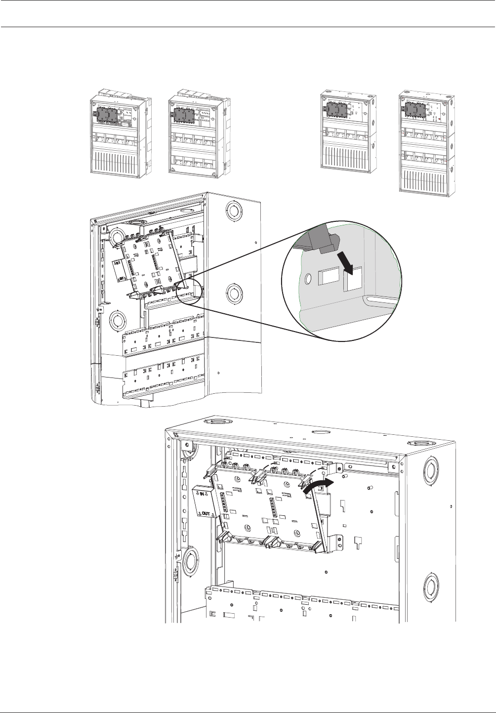
Modular Fire Panel Installation | en 81
Bosch Sicherheitssysteme GmbH System Information 09.2017 | 11.3 | F.01U.028.089
4.7.3 Panel Rail Installation
Short rail installation
HCP 0006 A HBC 0010 ACPH 0006 A MPH 0010 A
Figure4.35: PRS-0002-C installation
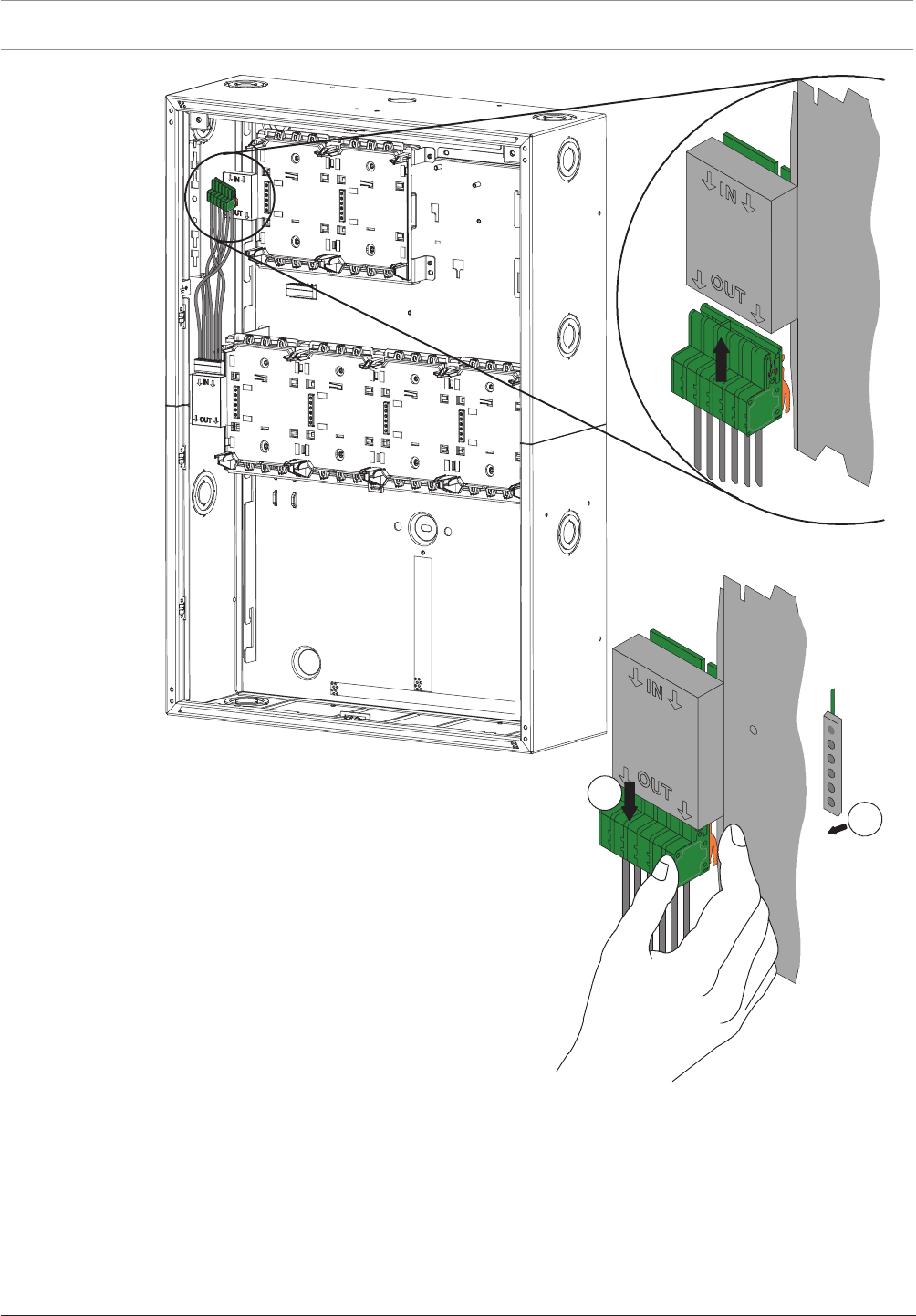
82 en | Installation Modular Fire Panel
09.2017 | 11.3 | F.01U.028.089 System Information Bosch Sicherheitssysteme GmbH
1
2
Figure4.36: Connection of panel rail
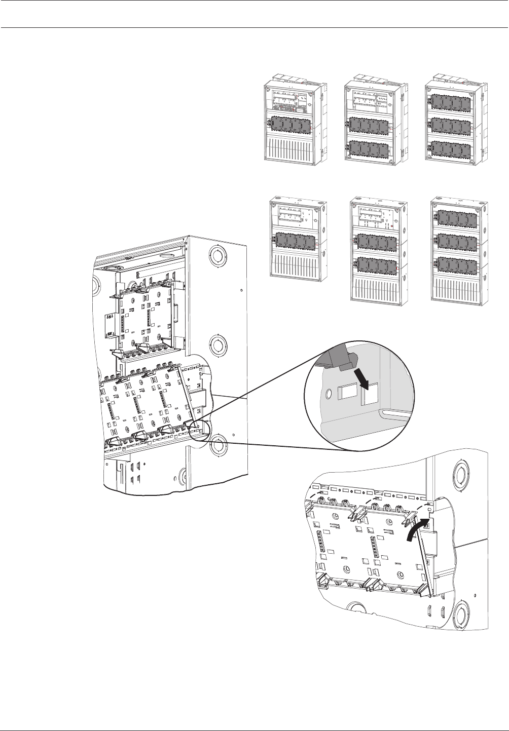
Modular Fire Panel Installation | en 83
Bosch Sicherheitssysteme GmbH System Information 09.2017 | 11.3 | F.01U.028.089
Long rail installation
HCP 0006 A HBC 0010 A HBE 0012 A
CPH 0006 A MPH 0010 A EPH 0012 A
Figure4.37: PRD0004A installation

84 en | Installation Modular Fire Panel
09.2017 | 11.3 | F.01U.028.089 System Information Bosch Sicherheitssysteme GmbH
1
2
Figure4.38: Connection of panel rail
4.8 MPCPanel Controller
The panel controller with the operating and display unit is the central element of the fire
detection system.
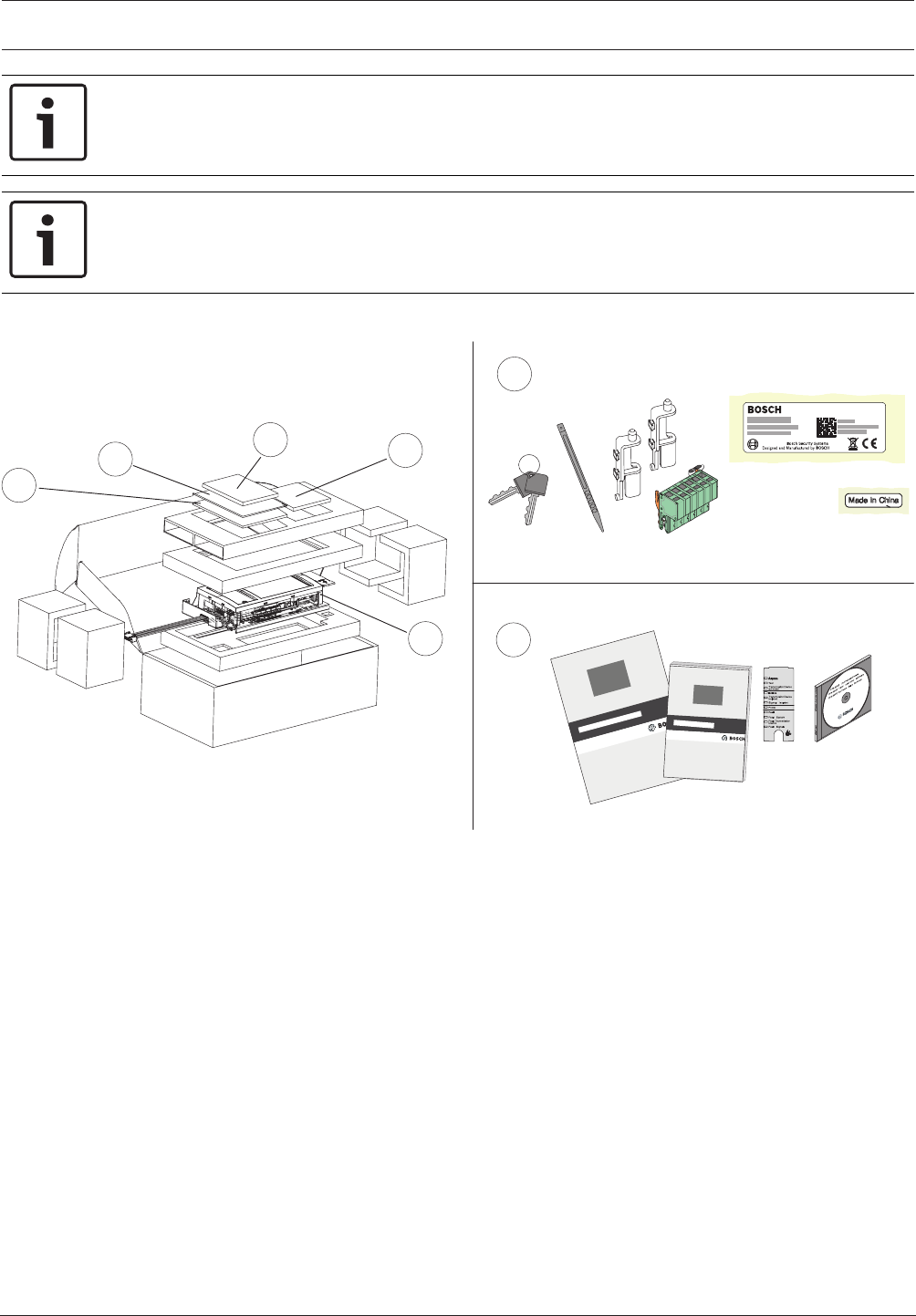
Modular Fire Panel Installation | en 85
Bosch Sicherheitssysteme GmbH System Information 09.2017 | 11.3 | F.01U.028.089
Notice!
Installation must only be performed by authorized and specialized personnel!
Notice!
The CD includes the FSP-5000-RPS Programming Software and the required product
documentation of the panel.
The technical data can be found in MPC, page 148.
2
2
1
32
1
2
cs ,QVWDODFQ¯SU¯UXFND
da Installationsvejledning
de Installationsanleitung
elOδηγϊες σuvαρμολόγησης
en Installation Guide
es Guía de instalación
fr Manuel d’installation
hr 8SXWH]DLQVWDODFLMX
hu 7HOHS¯W«VL¼WPXWDWµ
itGuida di installazione
nlInstallatiehandleiding
pl ,QVWUXNFMDLQVWDODF\MQD
pt Guia de Instalação
ro *KLGGHLQVWDODUH
ru ̷͚͕͉͕͙͉͕͖͕͚͙͑͋͘͘D͔͕͉͑H
sv Installationshandledning
sl 1DYRGLOD]DQDPHVWLWHY
tr Kurulum Klavuzu
en Operation Guide
Figure4.39: Scope of delivery for MPC
Functional Description
The panel controller controls all components in the system and has the following functional
elements
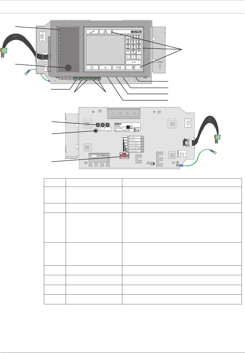
86 en | Installation Modular Fire Panel
09.2017 | 11.3 | F.01U.028.089 System Information Bosch Sicherheitssysteme GmbH
RS232
USB Device
IN1 / GND / IN2
2 x CAN1 2 x CAN2
CAN Bus
CAN Bus
12
5
6
78
3
4
2 x Ethernet (RJ45)
USB Host
Figure4.40: MPC functional elements
Position Designation Function
1 Touch screen Operation of the panel using virtual keys and variable
display windows
2 22 permanent keys Standard inputs
3 12 LEDs Display operating status.
The LED strip can be provided with a labeling strip. A
country-specific insert strip is enclosed with the
operating instructions.
4 Key switch Two switch positions, freely programmable, e.g. for
switching between day/night mode or activating/
deactivating local alarms
5 3 rotary switches Address setting
6 Reboot button Panel hardware reset
7 6-pin DIP switch Configuration setting
8 Grounding cable Panel controller grounding
Networking and Interfaces
The panel controller has
– 2 CAN interfaces (CAN1/CAN2) for networking
– 2 Ethernet interfaces (ETH1/ETH2) für Vernetzung
– 2 signal inputs (IN1/IN2)
– 1 USB and 1 RS232 interface
Note the maximum cable length of 2m for connection to the USB and RS232 interface.
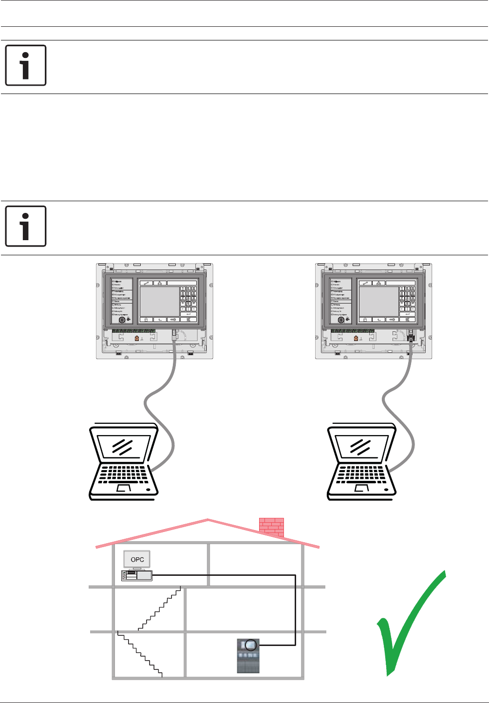
Modular Fire Panel Installation | en 87
Bosch Sicherheitssysteme GmbH System Information 09.2017 | 11.3 | F.01U.028.089
Notice!
You will find detailed information about the CAN and Ethernet networking of the panels in the
Networking Guide available for download at www.boschsecurity.com.
When connecting to a building management system (BIS) via an OPC server and Ethernet
100BaseTX in multiple building networks, you must clarify with the network administrator
whether
1. the network is designed for multiple building connections (e. g. there must be no
technical interference due to differences in grounding potential);
2. the bandwidth of the bus users is sufficient for the network.
Information about address setting and configuration in the network can be found in section .
Notice!
For detaiIed information about the installation und configuration of the OPC server see the
FSM-5000-OPC-Server manual.
USB Device RS232
max. 3 m
max. 3 m
Figure4.41: MPC, USB and RS232 interfaces
OPC
Server
Ethernet
100BaseTX
FPA-5000
FPA-1200
0
1
2
Figure4.42: MPC connection to BIS via OPC server

88 en | Installation Modular Fire Panel
09.2017 | 11.3 | F.01U.028.089 System Information Bosch Sicherheitssysteme GmbH
Installation
The MPC Panel Controller can be installed in the following housings: CPH 0006 A, MPH 0010
A, HCP 0006 A and HBC 0010 A.
For installation, follow the instructions on the following pages.
Notes:
– Make sure the Panel Rail Short is installed before you install the panel controller.
– Secure the grounding cable at the screw provided on the housing (4).
– Plug the cable into the IN slot on the Panel Rail Short (6).
Caution: Connection at the OUT slot or to a Panel Rail Long is not permissible.
– Plug the terminal element for the data bus into the OUT slot on the last occupied panel
rail (8).
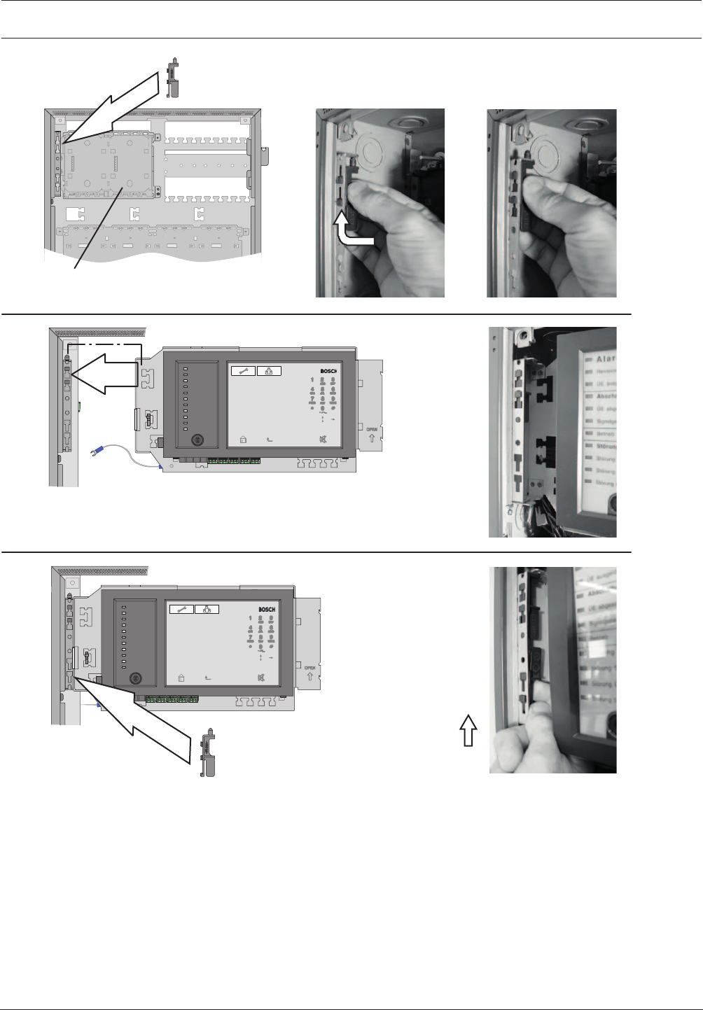
Modular Fire Panel Installation | en 89
Bosch Sicherheitssysteme GmbH System Information 09.2017 | 11.3 | F.01U.028.089
PRS-0002-C
1.
2.
3.
Figure4.43: MPC installation (1-3)
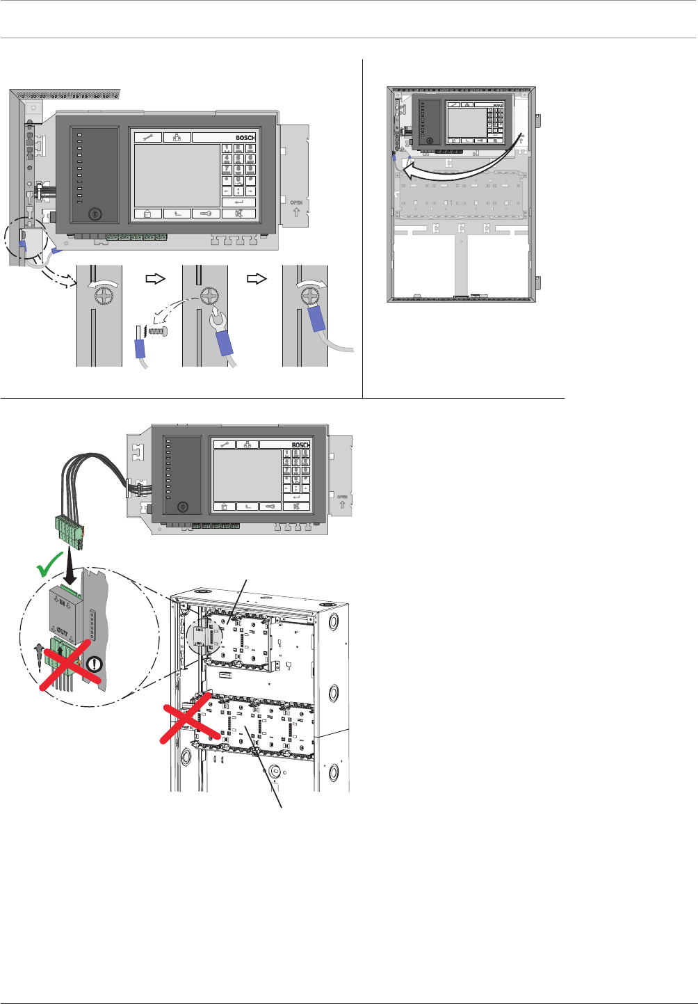
90 en | Installation Modular Fire Panel
09.2017 | 11.3 | F.01U.028.089 System Information Bosch Sicherheitssysteme GmbH
5.
6.
4.
PRS-0002-C
PRD-0004-A
Figure4.44: MPC installation (4-6)
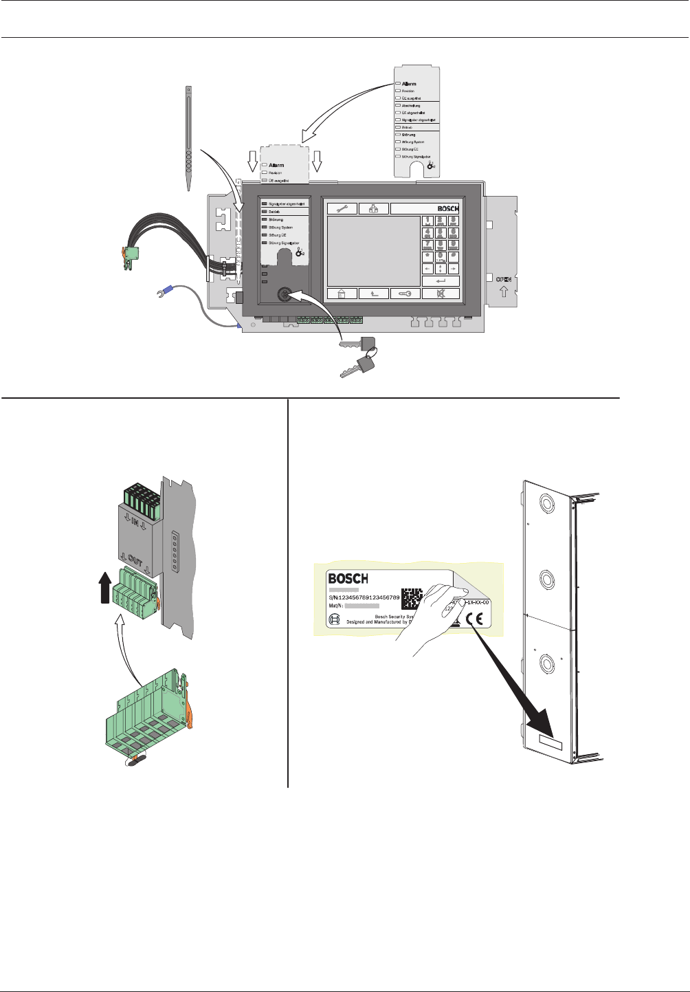
Modular Fire Panel Installation | en 91
Bosch Sicherheitssysteme GmbH System Information 09.2017 | 11.3 | F.01U.028.089
7.
8. 9.
Bosch xxxxxxx xxxxx
xxxxx xxxx
Figure4.45: MPC installation (7-9)
Address Cards ADCxxxxA
Address cards are used to specify the number of possible detection points.
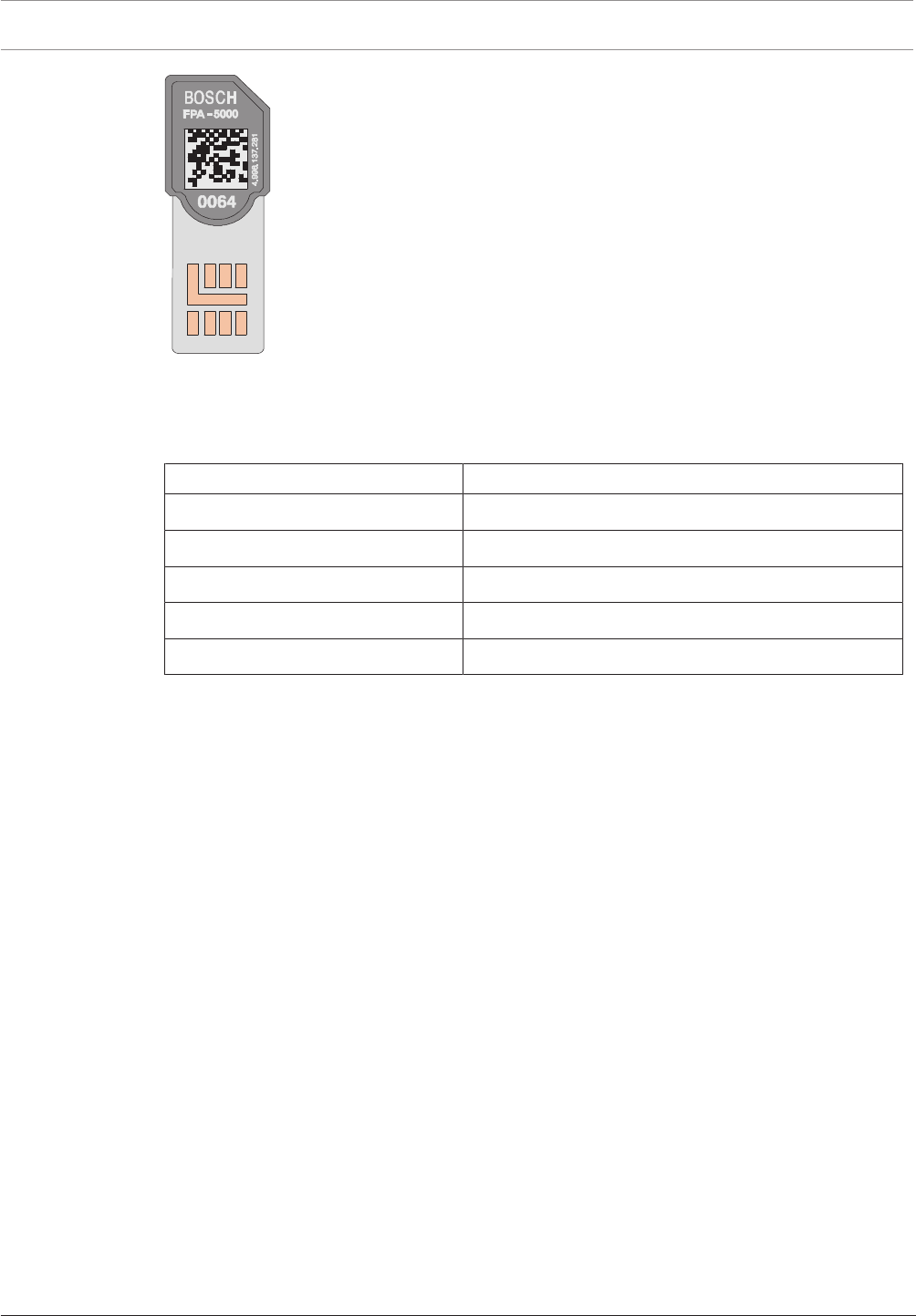
92 en | Installation Modular Fire Panel
09.2017 | 11.3 | F.01U.028.089 System Information Bosch Sicherheitssysteme GmbH
Figure4.46: ADCXXXX A address cards
One panel can be equipped with up to four address cards each with 64, 128, 512, 1024 or
2048 addresses, depending on requirements. The address cards are plugged into slots on the
back of the panel controller. The address cards can be used in any order.
Designation Description
ADC 0064 A SIM card with 64 addresses
ADC 0128 A SIM card with 128 addresses
ADC 0512 A SIM card with 512 addresses
ADC 1024 A SIM card with 1024 addresses
ADC-2048-A SIM card with 2048 addresses
When selecting the address card, note:
– Each module, each monitored module input and each LSN element occupies a detection
point (an address).
– An FPA-5000 can manage up to 4096 addresses.
A detailed explanation of addresses and detection points can be found starting on Detection
Points, page 27.
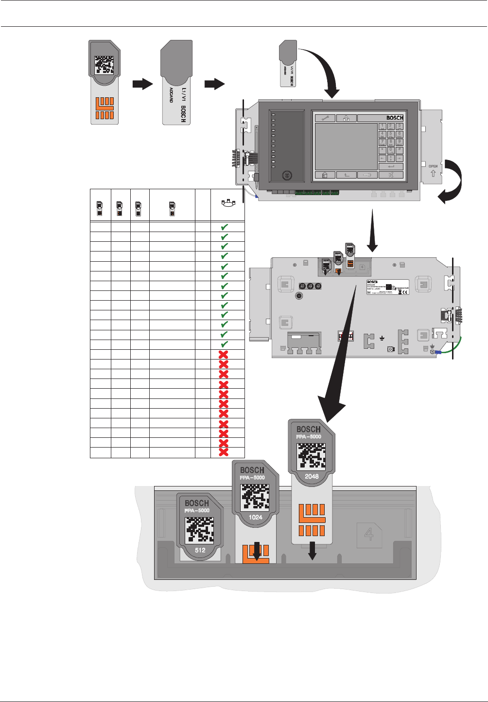
Modular Fire Panel Installation | en 93
Bosch Sicherheitssysteme GmbH System Information 09.2017 | 11.3 | F.01U.028.089
F.01U.076.111
FPA-5000
BOSCH
2048
F.01U.076.111
4.998.137.284
4.998.137.283
1234
≤ 2048
X 0064
X
X
X
X
X
0128
0128
0128
0128
0128
0128
0128
X
X
X
0512
0128 0512
0128
0512
0512
0512
0128
0128
0512
0512
1024
1024
1024
1024
1024
1024
1024
0512
0064
0512
0128
0128
1024
0128
0512
OPC/VA/OPC+VA
OPC/VA/OPC+VA
OPC/VA/OPC+VA
OPC/VA/OPC+VA
OPC/VA/OPC+VA
OPC/VA/OPC+VA
OPC/VA/OPC+VA
OPC/VA/OPC+VA
OPC/VA/OPC+VA
OPC/VA/OPC+VA
OPC/VA/OPC+VA
VA
VA
VA
VA
VA
VA
VA
0128
0128
0512
0064
0128
0512
0064
0128
0512
0064
0128
0512
1024
0128
0512
2048
2048
2048
1024
2048
0512
2048
2048
1024
2048
1024
2048
0512
0128
0512
1024
0128
1024
0512
1024
Σ
0064
0128
0256
0384
0512
0640
0768
0896
1024
1280
1536
1728
2048
2176
2240
2560
2688
2752
3072
3200
3264
3584
3712
4096
/OPC/OPC+VA
Figure4.47: Address Cards ADCxxxxA
ADC‑5000‑OPC License Key
The ADC‑5000‑OPC License Key is a special address card that enables communication
between an OPC server and an FPA-5000 Modular Fire Panel.
The fire panels FPA-1200 or FPA-5000 can be connected to the Fire Monitoring System
FSM-2500 or FSM-5000 via an Ethernet connection. The connection must be enabled with an
ADC‑5000‑OPC License Key.

94 en | Installation Modular Fire Panel
09.2017 | 11.3 | F.01U.028.089 System Information Bosch Sicherheitssysteme GmbH
Although all the panels in a network can be connected to the OPC server, the license key only
needs to be fitted to one of them.
The address cards can be in any order in a panel.
ADC‑5000‑VA Licence Key
The ADC‑5000‑VA enables the IP Ethernet data interaction between the FPA-5000/FPA-1200
fire panel and the Praesideo/PAVIRO voice alarm system. The activation of all programmed
voice zones is realized by only one data connection without additional devices.
ADC‑5000‑OPC-VA Licence Key
OPC server connection and Praesideo/PAVIRO voice alarm system are independently activated
with only one licence key.
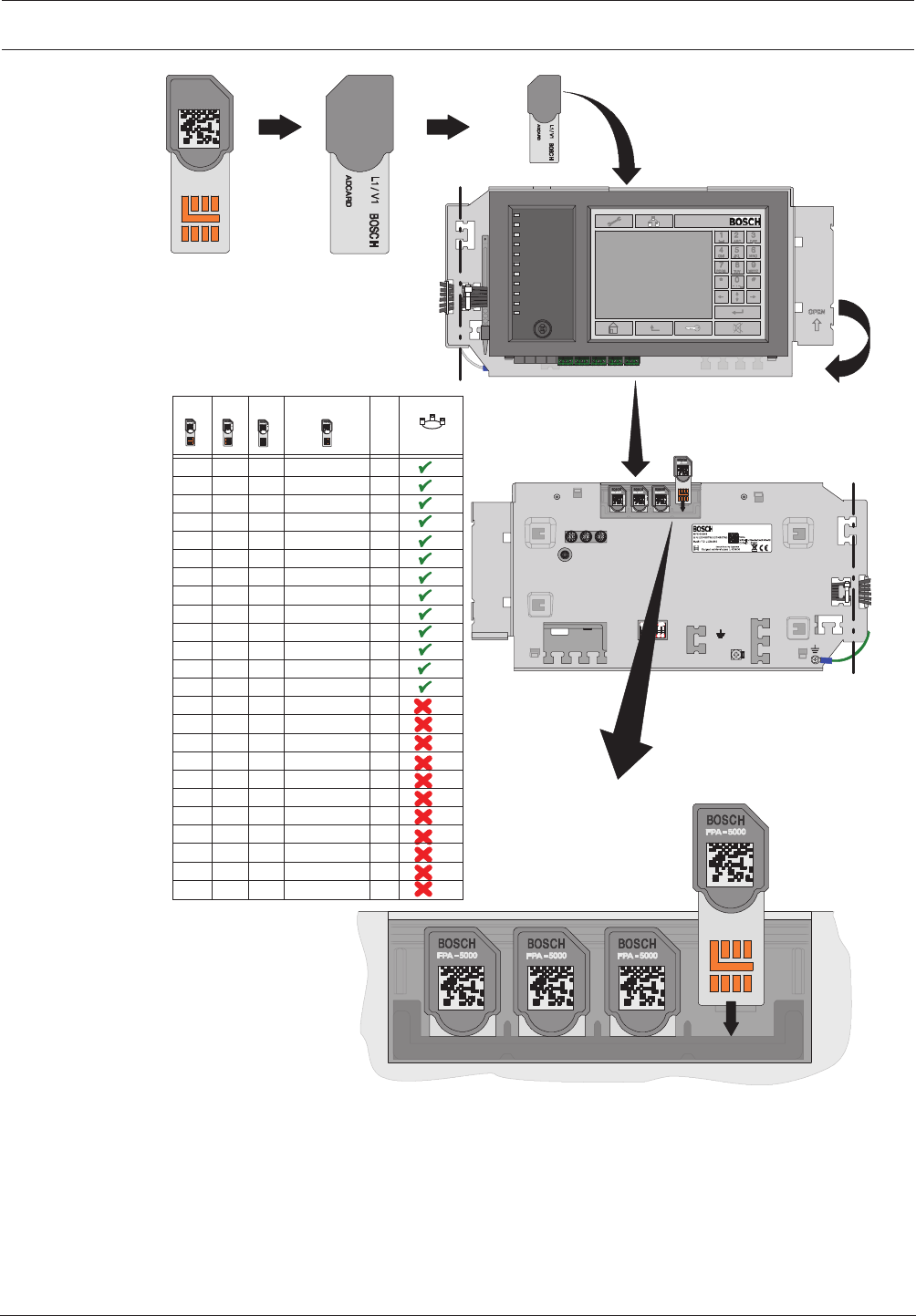
Modular Fire Panel Installation | en 95
Bosch Sicherheitssysteme GmbH System Information 09.2017 | 11.3 | F.01U.028.089
F.01U.076.111
F.01U.076.112
4.998.137.284
4.998.137.283
F.01U.076.112
OPC
FPA-5000
OPC
2048
1024512
BOSCH
1234
≤ 2048
X 0064
X
X
X
X
X
0128
0128
0128
0128
0128
0128
0128
X
X
X
0512
0128 0512
0128
0512
0512
0512
0128
0128
0512
0512
1024
1024
1024
1024
1024
1024
1024
0512
0064
0512
0128
0128
1024
0128
0512
OPC/VA/OPC+VA
OPC/VA/OPC+VA
OPC/VA/OPC+VA
OPC/VA/OPC+VA
OPC/VA/OPC+VA
OPC/VA/OPC+VA
OPC/VA/OPC+VA
OPC/VA/OPC+VA
OPC/VA/OPC+VA
OPC/VA/OPC+VA
OPC/VA/OPC+VA
VA
VA
VA
VA
VA
VA
VA
0128
0128
0512
0064
0128
0512
0064
0128
0512
0064
0128
0512
1024
0128
0512
2048
2048
2048
1024
2048
0512
2048
2048
1024
2048
1024
2048
0512
0128
0512
1024
0128
1024
0512
1024
Σ
0064
0128
0256
0384
0512
0640
0768
0896
1024
1280
1536
1728
2048
2176
2240
2560
2688
2752
3072
3200
3264
3584
3712
4096
/OPC/OPC+VA
Figure4.48: ADC‑5000‑OPC License Key
Addressing and Settings in the Network
The panels and remote keypads are identified in the network by a unique address. This
address is set on the rotary switches and is known as the rotary switch number (RSN) (see
the figures in the circle on the circuit diagrams). The rotary switches are located on the rear of
the panel controller (see ).
Note the address on the sign below the rotary switches (see , step 2).
The DIP switches are located on the rear of the panel controller (see ).
Mark the selected setting on the sign above the DIP switches (see , step 4).

96 en | Installation Modular Fire Panel
09.2017 | 11.3 | F.01U.028.089 System Information Bosch Sicherheitssysteme GmbH
Notice!
Redundant panels must have identical addresses.
Notice!
You will find detailed information about the CAN and Ethernet networking of the panels in the
Networking Guide available for download at www.boschsecurity.com.
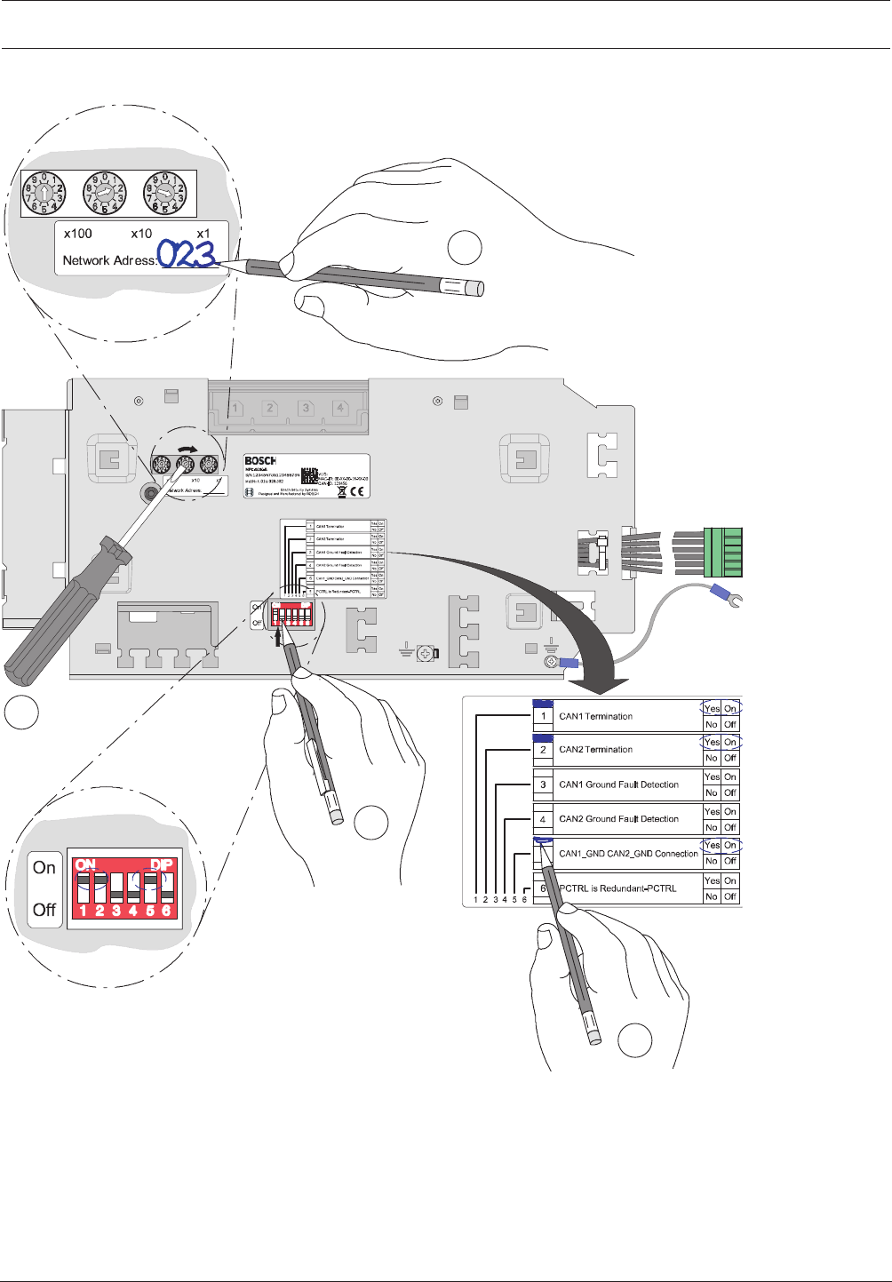
Modular Fire Panel Installation | en 97
Bosch Sicherheitssysteme GmbH System Information 09.2017 | 11.3 | F.01U.028.089
Addressing and Configuration of MPCPanel Controller
2
4
3
1
Figure4.49: MPCPanel Controller, addressing
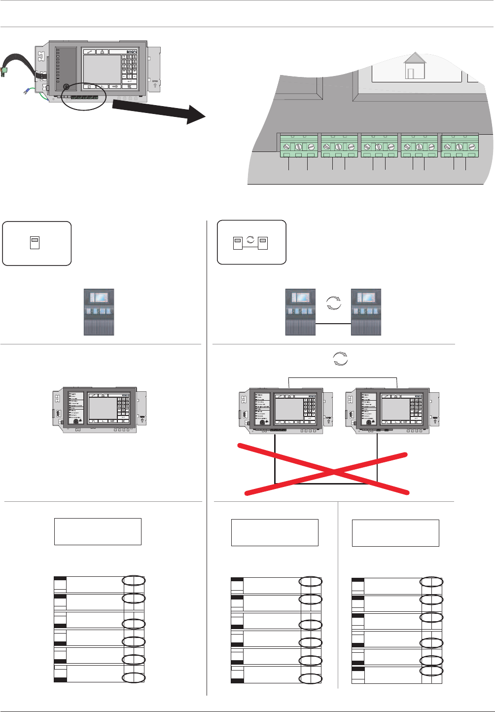
98 en | Installation Modular Fire Panel
09.2017 | 11.3 | F.01U.028.089 System Information Bosch Sicherheitssysteme GmbH
GND IN2IN1 GLHGLHGLHGLH
CAN1CAN1CAN2
CAN2
Figure4.50: MPCPanel Controller, network connections
Standalone Panel and Redundant Standalone Panel
FPA-5000FPA-5000
001001 001
CAN1CAN1
CAN internal
001
Redundant-PCTRL
PCTRL is
CAN2 Ground Fault
Detection
CAN1 Ground Fault
Detection
1On
On
On
On
On
On
CAN1 Termination
CAN1_GND CAN2_GND
CAN2 Termination
Connection
No
No
No
No
No
No Off
Off
Off
Off
Off
Off
Yes
Yes
Yes
Yes
Yes
Yes
2
3
4
5
6
x100 x10 x1
Network Address: ________ 001
Redundant-PCTRL
PCTRL is
CAN2 Ground Fault
Detection
CAN1 Ground Fault
Detection
1On
On
On
On
On
On
CAN1 Termination
CAN1_GND CAN2_GND
CAN2 Termination
Connection
No
No
No
No
No
No Off
Off
Off
Off
Off
Off
Yes
Yes
Yes
Yes
Yes
Yes
2
3
4
5
6
x100 x10 x1
Network Address: ________ Network Address: ________
001
Redundant-PCTRL
PCTRL is
CAN2 Ground Fault
Detection
CAN1 Ground Fault
Detection
1On
On
On
On
On
On
CAN1 Termination
CAN1_GND CAN2_GND
CAN2 Termination
Connection
No
No
No
No
No
No Off
Off
Off
Off
Off
Off
Yes
Yes
Yes
Yes
Yes
Yes
2
3
4
5
6
x100 x10 x1
Figure4.51: Standalone panel (regular and redundant): Configuration in network

Modular Fire Panel Installation | en 99
Bosch Sicherheitssysteme GmbH System Information 09.2017 | 11.3 | F.01U.028.089
See also
– Connection to BIS, page 23
4.9 Functional Modules
Each functional module has been developed for a specific function within the fire detection
system.
All modules feature:
– robust, totally enclosed housings
– replacement during operation
– pluggable connection terminals
– automatic detection
The plug contacts in the panel rail provide the power supply to the modules and handle all
data traffic between the module and control panel.
The module is automatically identified as soon as it is plugged in. Contact with peripherals is
achieved with compact plug/screw terminals. If a module is replaced
the plug/screw terminals are simply re-fitted, with no need for complex rewiring.
Functional settings on the modules are made using the FSP-5000-RPS programming software.
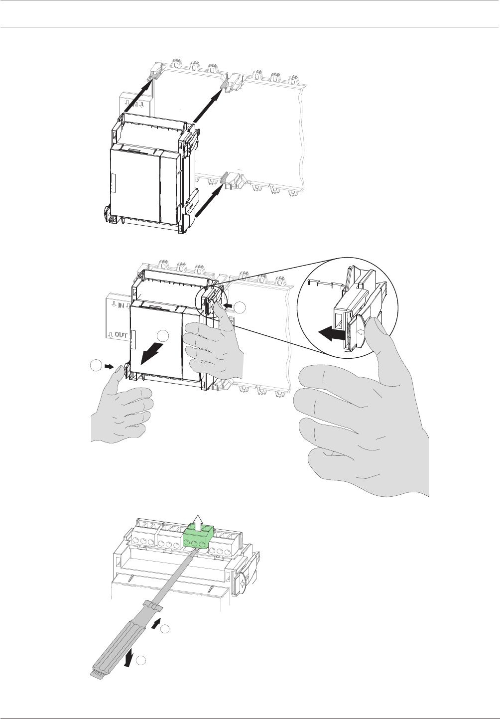
100 en | Installation Modular Fire Panel
09.2017 | 11.3 | F.01U.028.089 System Information Bosch Sicherheitssysteme GmbH
4.9.1 Installation and Removal
2
1
3
Figure4.52: Installation and removal of functional modules
2
1
Figure4.53: Detaching the screw terminal block
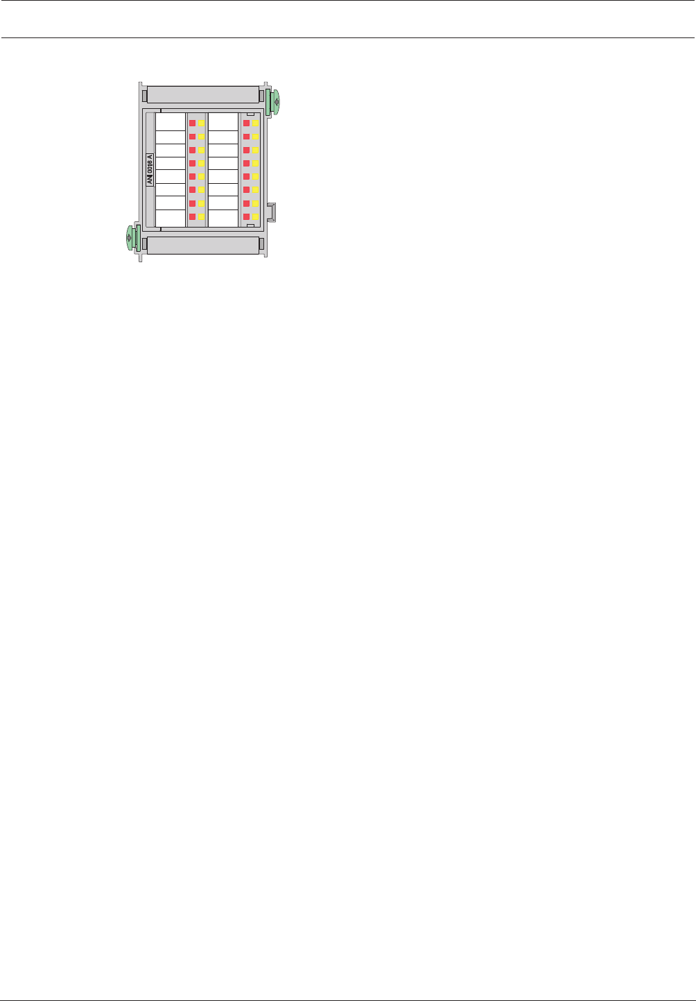
Modular Fire Panel Installation | en 101
Bosch Sicherheitssysteme GmbH System Information 09.2017 | 11.3 | F.01U.028.089
4.9.2 ANI0016A Annunciator Module
Figure4.54: ANI0016A Annunciator Module
The annunciator module has 16 red and 16 yellow LEDs for displaying the operating states of
16definable detection points.
The activation of each LED is defined using the FSP-5000-RPS programming software.
This defines which detection points will activate the LEDs in which state.
The technical data can be found in ANI0016A Annunciator Module, page 150.
4.9.3 BCM‑0000‑B Battery Controller Module
The BCM-0000-B Battery Controller Module monitors the power supply of the entire panel and
regulates the temperature and time-controlled charging of up to four batteries.
The following functions are available using the keys on the module (1):
– The four LEDs on the module light up as a confirmation and LED test each time the key is
pressed.
– If the batteries have a voltage of between 18V and 21V, the battery charging procedure
can be started manually. Please note that a power supply must be available.
– The 24V switch outputs can be reset.
The switch output is deactivated if a fault occurs.
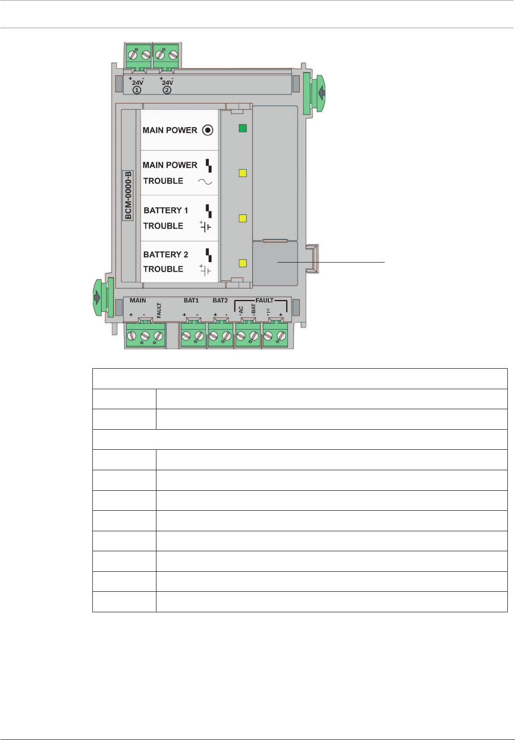
102 en | Installation Modular Fire Panel
09.2017 | 11.3 | F.01U.028.089 System Information Bosch Sicherheitssysteme GmbH
24 V
1
Figure4.55: BCM‑0000‑B Battery Controller Module
Top connections, from left to right
24V + | - Switch output +24V max. 2.8A (battery buffered, optional)
24V + | - Switch output +24V max. 2.8A (battery buffered, optional)
Lower connections, from left to right
MAIN + | - Power supply unit connection
MAIN FAULT Signal input for power supply unit fault
BAT1 + | - Battery pair 1 connection
BAT2 + | - Battery pair 2 connection
FAULT AC - Switch output for mains fault
FAULT BAT - Switch output for battery fault
FAULTΣ - Switch output for collective fault
FAULT +24V Switch output +
Notes
– The module can only be used with the MPC Panel Controller from software version 2.1
onwards.
– If the FPA-5000 Fire Panel is not supplied with mains power, it can only be started
– if a battery pair is connected to BAT1 and
– no second battery pair is connected to BAT2.

Modular Fire Panel Installation | en 103
Bosch Sicherheitssysteme GmbH System Information 09.2017 | 11.3 | F.01U.028.089
If batteries are connected to the BAT2 connection on the module, the system will
report a battery fault and will not start. This battery fault can only be reset if the
FPA-5000 Fire Panel is supplied with mains power and the BAT 2 connection is
configured.
– If the FPA-5000 Fire Panel is not supplied with mains power for an extended period,
ensure that the batteries are disconnected.
– When using the module in the FPP‑5000 External Power Supply, only one battery pair can
be charged (see FPP‑5000 External Power Supply Unit Kit 24V/6A, page 121).
– Refer to the configuration information in Configuration of BCM Battery Controller Module,
page 36.
The technical data can be found in BCM‑0000‑B Battery Controller Module, page 150.
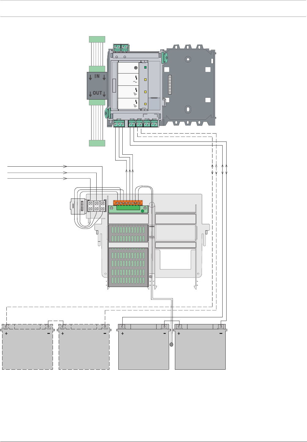
104 en | Installation Modular Fire Panel
09.2017 | 11.3 | F.01U.028.089 System Information Bosch Sicherheitssysteme GmbH
Wiring Diagram
L1
N
1 8
G
BCM
UPS 2416 A
MPC
24V DC
PRD 0004 A
MAIN POWER
MAIN POWER
TROUBLE
TROUBLE
TROUBLE
BATTERY 1
BATTERY 2
12 V / 28 Ah
(12 V / 45 Ah)
12 V / 28 Ah
(12 V / 45 Ah)
12 V / 28 Ah
(12 V / 45 Ah)
12 V / 28 Ah
(12 V / 45 Ah)
B
-0000-MCB
+ - + -
24V 24V
MAIN BAT1 BAT2 FAULT
TLUAF
C
A
T
AB
MAIN POWER
MAIN POWER
TROUBLE
TROUBLE
TROUBLE
BATTERY 1
BATTERY 2
+ - + - + - - - - +
Σ
12
V 42
PRS-0002-C
Figure4.56: Wiring diagram for BCM‑0000‑B
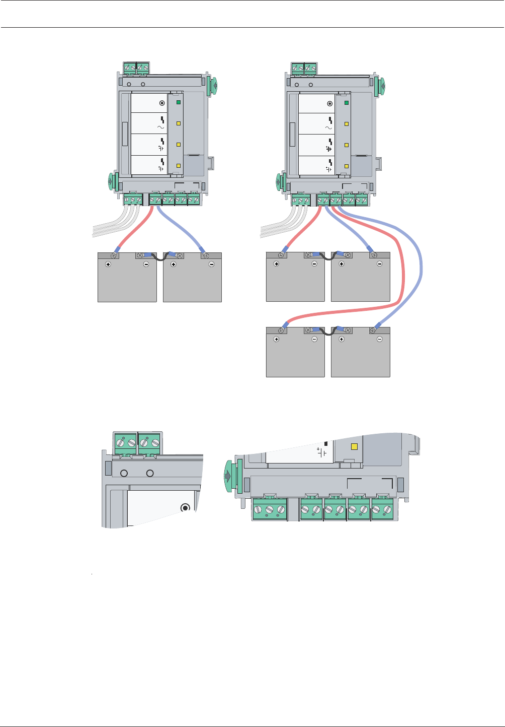
Modular Fire Panel Installation | en 105
Bosch Sicherheitssysteme GmbH System Information 09.2017 | 11.3 | F.01U.028.089
Battery Connection
B
-
00
0
0-MCB
+ - + -
24V 24V
MAIN BAT1 BAT2 FAULT
T
LUA
F
CA -
TA
B
-
MAIN POWER
MAIN POWER
TROUBLE
TROUBLE
TROUBLE
BATTERY 1
BATTERY 2
+ - + - + - +
-Σ
1 2
B-
00
0
0
-
M
CB
+ - + -
24V 24V
MAIN BAT1 BAT2 FAULT
T
LU
AF
MAIN POWER
MAIN POWER
TROUBLE
TROUBLE
TROUBLE
BATTERY 1
BATTERY 2
1 2
CA -
T
A
B
-
+ - + - + - +
-Σ
V 4
2
V 42
+ - + -
24V 24V
MAIN POWER
1 2
MAIN BAT1 BAT2 FAULT
T
LUAF
CA
-
TAB
-
TROUBLE
BATTERY 2
+ - + - + -
-Σ
V 4
2
+
Figure4.57: BCM‑0000‑B battery connection
Cable Set
A cable set is supplied and contains 2 connection cables: BCM/battery (90cm) and battery/
battery (17cm).
If you want to install the batteries in a power supply housing, you require the CBB0000A
Cable Set (BCM/battery cable length 180cm.

106 en | Installation Modular Fire Panel
09.2017 | 11.3 | F.01U.028.089 System Information Bosch Sicherheitssysteme GmbH
!
Warning!
There is a risk of injury if no temperature sensor is positioned between the batteries.
The temperature sensor is supplied with the power supply bracket and protects the batteries
against overheating. If the sensor is not positioned correctly, the batteries can overheat and
explode.
Position the temperature sensor between the batteries.
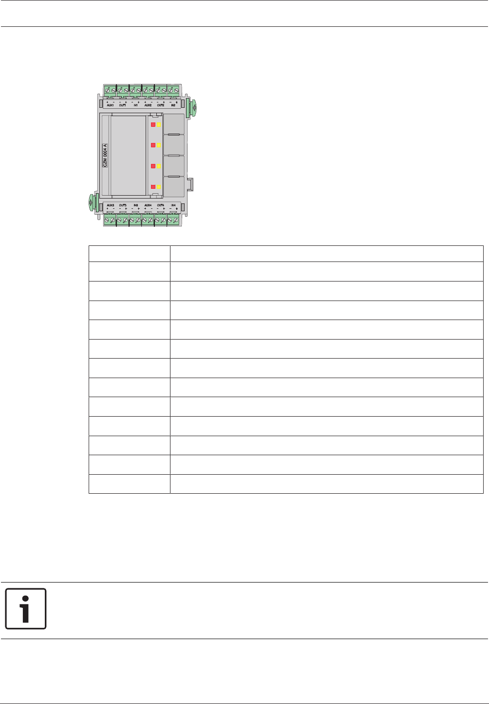
Modular Fire Panel Installation | en 107
Bosch Sicherheitssysteme GmbH System Information 09.2017 | 11.3 | F.01U.028.089
4.9.4 CZM0004A 4Zone Conventional Module
The CZM0004A Conventional Module enables particular existing conventional peripherals to
be connected. It provides connections for four monitored conventional lines.
Figure4.58: CZM0004A 4Zone Conventional Module
Labeling Connection
AUX1 + | AUX1 - 24VDC auxiliary power supply zone1
OUT1 - | OUT1 + Zone1 output low/zone1 output high
IN1 - | IN1 + Zone1 input low/zone1 input high
AUX2 + | AUX2 - 24VDC auxiliary power supply zone2
OUT2 - | OUT2 + Zone2 output low/zone2 output high
IN2 - | IN2 + ClassA zone2 input low/classA zone2 input high
AUX3 + | AUX3 - 24VDC auxiliary power supply zone3
OUT3 - | OUT3 + Zone3 output low/zone3 output high
IN3 - | IN3 + ClassA zone3 input low/classA zone3 input high
AUX4 + | AUX4 - 24VDC auxiliary power supply zone4
OUT4 - | OUT4 + Zone4 output low/zone4 output high
IN4 - | IN4 + ClassA zone4 input low/classA zone4 input high
Notes
– All additional voltage outputs (AUX1-AUX4) can be switched on and off simultaneously.
– Two and four-wire conventional components can be connected.
– Note the maximum line resistance:
– 25Ohm for conventional lines with FMC-300-RW or automatic fire detectors
– 12Ohm for conventional lines with FMC-120-DKM call points
Notice!
To ensure that operation of the fire detection system complies with EN 54-13, each
conventional line must be terminated with EOL modules.
The EOL modules can be used with CZM modules from software version 1.1.10 onwards.
The technical data can be found in CZM0004A 4Zone Conventional Module, page 151.
4.9.5 ENO0000B Fire Service Interface Module
The ENO 0000 B is used to connect fire service equipment:
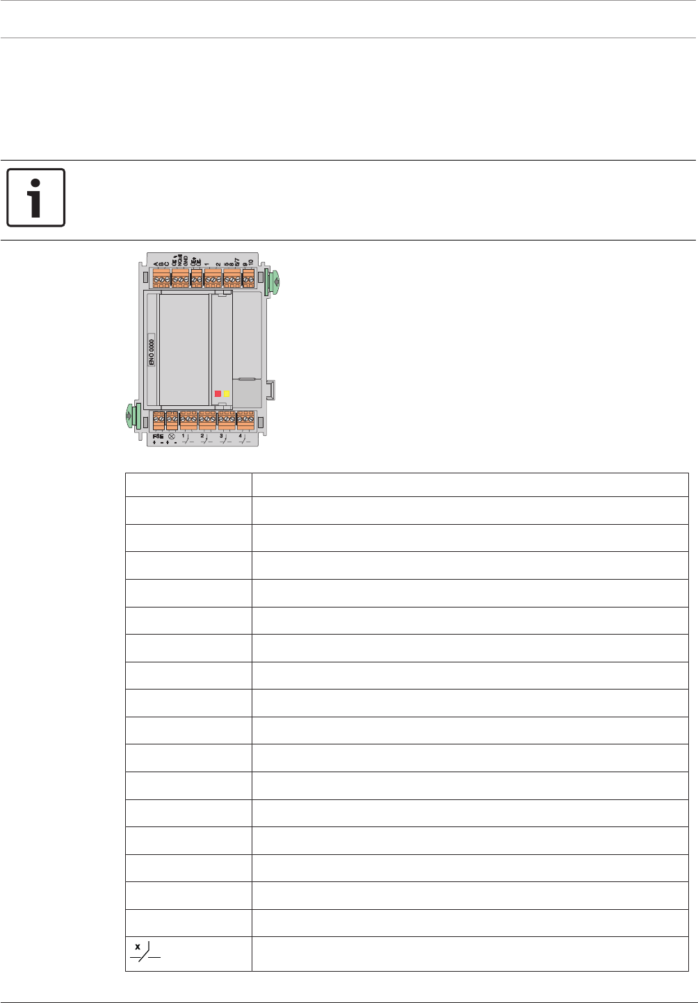
108 en | Installation Modular Fire Panel
09.2017 | 11.3 | F.01U.028.089 System Information Bosch Sicherheitssysteme GmbH
– Transmission device to the fire brigade
– Key deposit
– Signal lamp (e.g. BEGA flush-mounting lamp or BL 200)
– FSE release element monitoring
– Four freely programmable changeover relays
Notice!
The requirements of the local fire department must be taken into account during
programming.
The module is used almost exclusively in Germany.
Figure4.59: ENO0000B Fire Service Interface Module
Labeling Connection
A Ground
B Transmission unit control
C Feedback contact
ÜE Automatic dialer and transmission unit fault
NQuit Acknowledge
GND Ground
ÜE+ | ÜE- Power supply of transmission unit
1 Monitoring key deposit
2 Ground
5 Door release magnet, +12V/24V, approx. 10W
8 Key deposit lock monitoring
6 | 7 Ground
9 Heating, +24V, approx. 8W
10 Ground
FSE+ | − FSE release element monitoring
⊗ + | − Signal lamp, e.g. BEGA lamp +24V, approx. 10W
Relay 1-4
Information on the redundant connection of the module can be found in Redundancy, page 40.
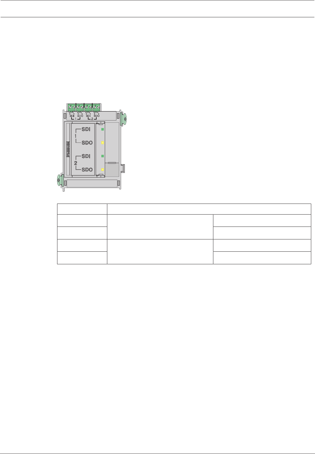
Modular Fire Panel Installation | en 109
Bosch Sicherheitssysteme GmbH System Information 09.2017 | 11.3 | F.01U.028.089
The technical data can be found in ENO0000B Fire Service Interface Module, page 152.
4.9.6 FPE‑5000‑UGM Interface Module
The FPE-5000-UGM Interface Module allows the FPA-5000 Modular Fire Panel or an FPA-5000/
FMR-5000-C network to be connected to a higher-level system such as the UGM or to fire
service devices such as FMF-FAT/FMF-FBF-FAT. The module provides two bi-directional
transmission paths.
The module has two LEDs per transmission path for indicating the status (green=
transmission, yellow= fault), and a key for testing the LEDs.
Figure4.60: FPE‑5000‑UGM Interface Module
Labeling Connection
SDI 1 + | - Transmission path 1 Data input + | -
SDO 1 + | - Data output + | -
SDI 2 + | - Transmission path 2 Data input + | -
SDO 2 + | - Data output + | -
Information on the redundant connection of the module can be found in Redundancy, page 40.
The technical data can be found in FPE‑5000‑UGM Interface Module, page 152.
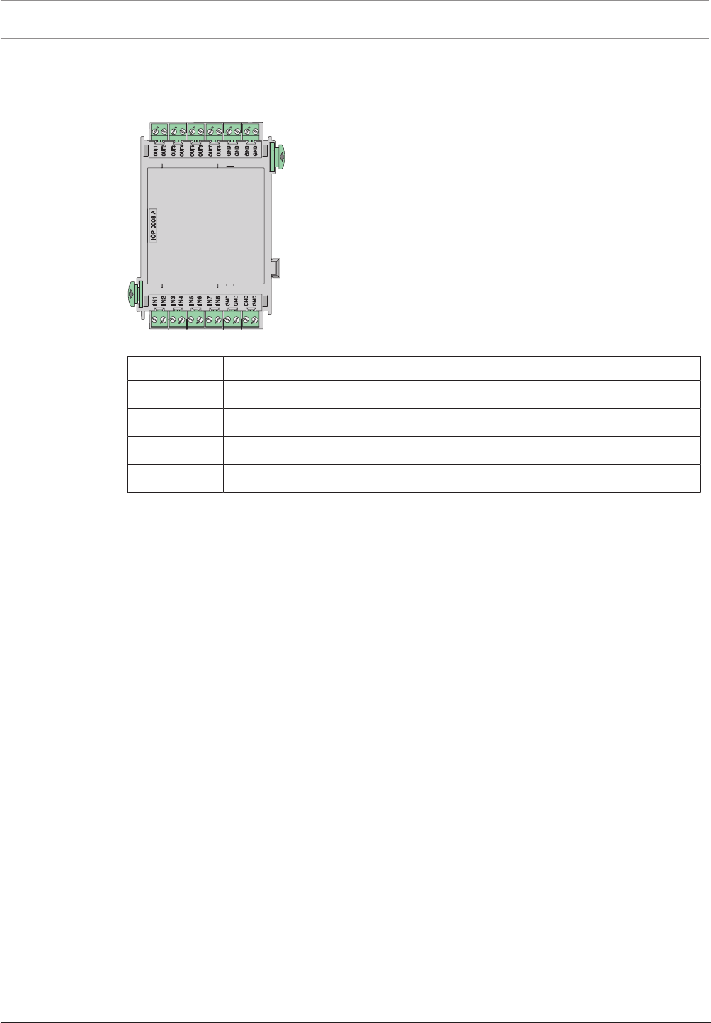
110 en | Installation Modular Fire Panel
09.2017 | 11.3 | F.01U.028.089 System Information Bosch Sicherheitssysteme GmbH
4.9.7 IOP0008A Input/Output Module
The IOP0008A Input/Output Module has 8 independent digital inputs and 8open collector
outputs for individual displays or for flexible connection of various electrical devices.
Figure4.61: IOP0008A Input/Output Module
Labeling Connection
OUT1-OUT8 Outputs, max. voltage of 35VDC at 1.5A per output (nominal 0.7A)
GND Ground
IN1-IN8 Inputs, max. voltage of 5VDC at 0.1mA per input
GND Ground
The technical data can be found in IOP0008A Input/Output Module, page 152.
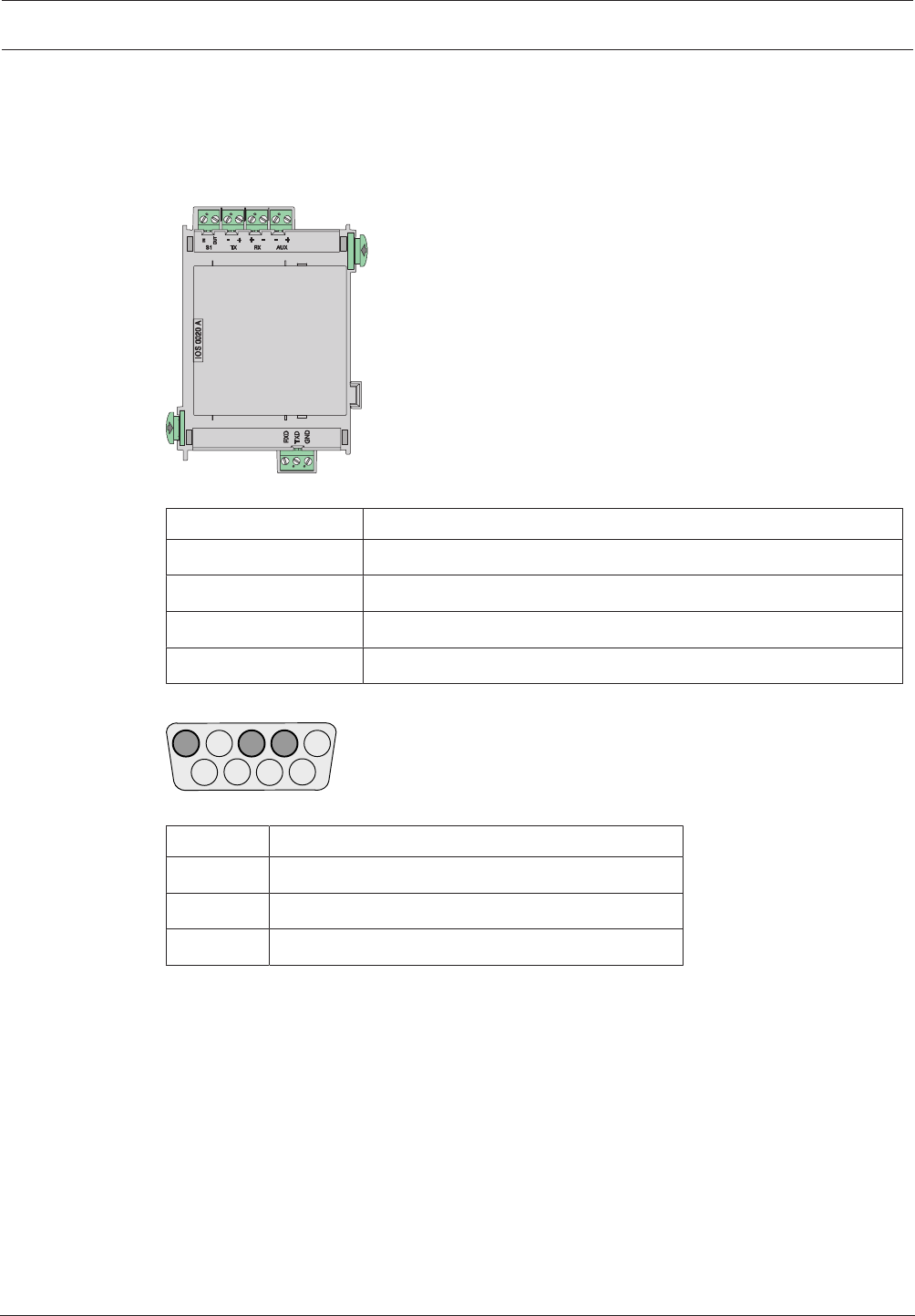
Modular Fire Panel Installation | en 111
Bosch Sicherheitssysteme GmbH System Information 09.2017 | 11.3 | F.01U.028.089
4.9.8 IOS0020A 20mA Communication Module
The 20mA communication module has an S1 interface, an RS232 interface (e.g. for
connecting a printer) and an S20 interface (20mA). The FAT2002 Fire Service Display Panel
or the THP2020A Thermal Printer is connected to the S20 interface. The Plena Voice Alarm
System can be connected via the RS232 interface.
Figure4.62: IOS0020A 20mA Communication Module
Labeling Connection
S1 IN | S1 OUT S1 interface
TX - | TX + | RX + | RX - S20 interface (20mA interface)
AUX - | AUX + Power supply +24VDC/max. 1.3A
RXD | TXD | GND RS232 interface
Assignment of DSUB9 Plug
543 2 1
9876
Figure4.63: DSUB9 plug
PIN no. Connection
2 TxD0
3 RxD0
5 GND
The technical data can be found in IOS0020A 20mA Communication Module, page 153.
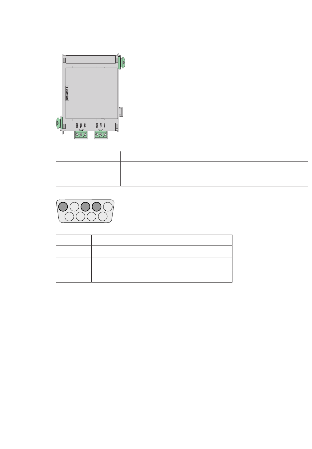
112 en | Installation Modular Fire Panel
09.2017 | 11.3 | F.01U.028.089 System Information Bosch Sicherheitssysteme GmbH
4.9.9 IOS0232A RS232 Communication Module
The module has two independent serial interfaces, which can be used to connect two devices,
e.g. a Plena Voice Alarm System, laptop or printer.
Figure4.64: IOS0232A RS232 Communication Module
Labeling Connection
RXD1 | TXD1 | GND RS232 interface 1
RXD2 | TXD2 | GND RS232 interface 2
Assignment of DSUB9 Plug
543 2 1
9876
Figure4.65: DSUB9 plug
PIN no. Connection
2 TxD0
3 RxD0
5 GND
The technical data can be found in IOS0232A RS232 Communication Module, page 153.
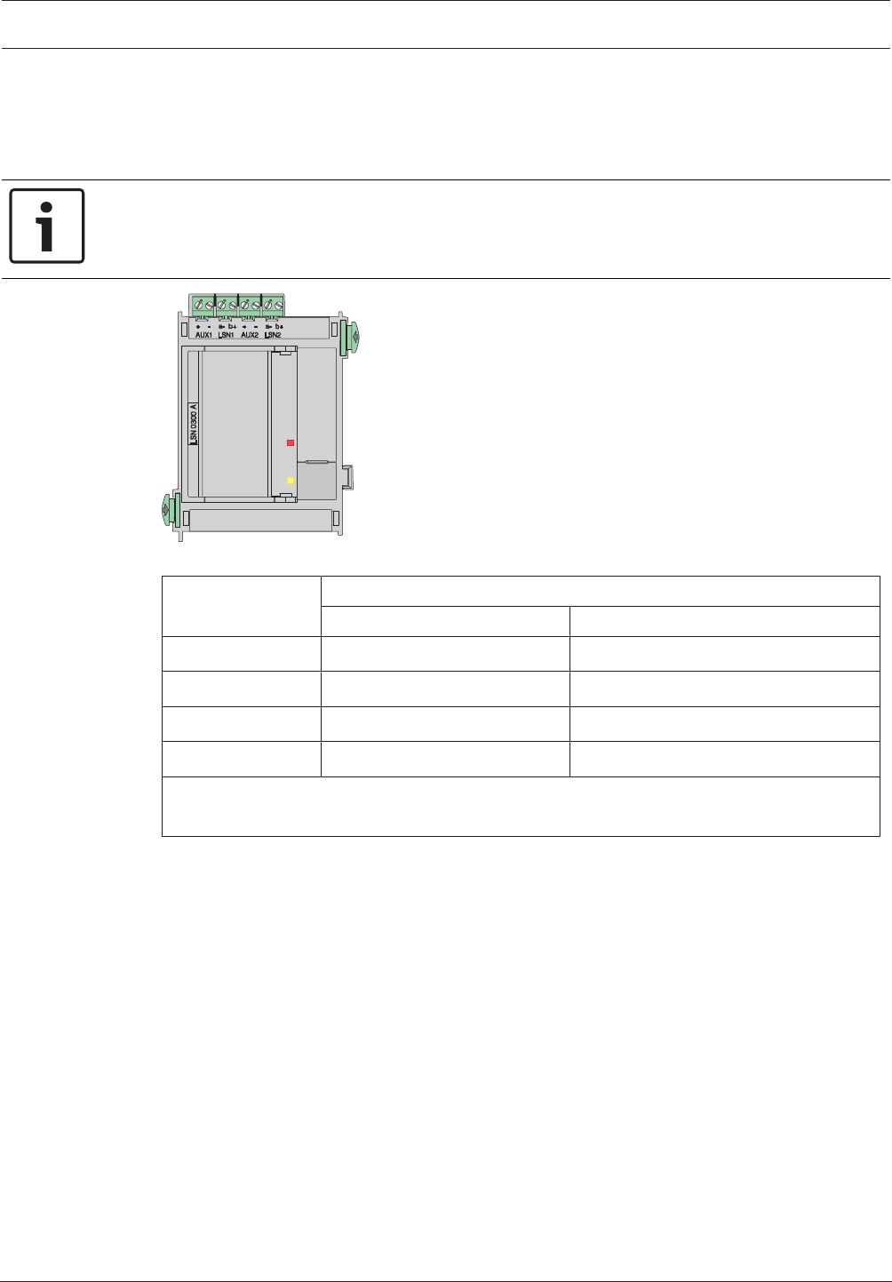
Modular Fire Panel Installation | en 113
Bosch Sicherheitssysteme GmbH System Information 09.2017 | 11.3 | F.01U.028.089
4.9.10 LSN0300A LSNimprovedModule 300mA
This module enables an LSN loop with up to 254 LSN improved elements or 127 classic LSN
elements to be connected, with a maximum line current of 300mA and a cable length of up to
1600m (depending on configuration and cable type).
Notice!
To ensure that the fire detection system is operated in compliance with EN 54‑13, each LSN
stub and T-tap must be terminated with EOL modules.
Figure4.66: LSN0300A LSNimprovedModule 300mA
Labeling Connection
LSN loop LSN stub
AUX1 + | AUX1 - Auxiliary power supply Auxiliary power supply for stub 1
LSN a1- | LSN b1+ LSN a1- / LSN b1+ outgoing Stub 1 LSN a1- / Stub 1 LSN b1+
AUX2 + | AUX2 - Auxiliary power supply* Auxiliary power supply for stub 2
LSN a2- | LSN b2+ LSN a2- / LSN b2+ incoming Stub 2 LSN a2- / Stub 2 LSN b2+
* The auxiliary voltage may only be fed back to AUX2 when isolators (ERT technology) are
used in the loop (suitable components include YBO-R/SCI isolators).
The technical data can be found in LSN0300A LSNimprovedModule 300mA, page 153.
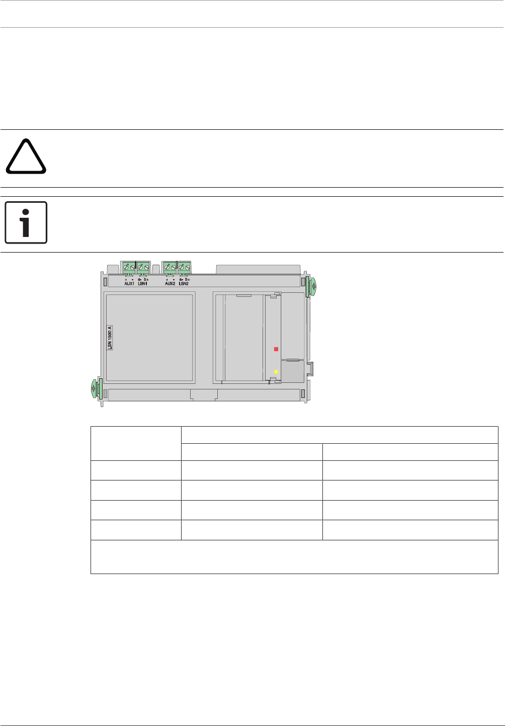
114 en | Installation Modular Fire Panel
09.2017 | 11.3 | F.01U.028.089 System Information Bosch Sicherheitssysteme GmbH
4.9.11 LSN1500A LSN improved Module 1500mA
This module can be used to connect an LSN loop with
– up to 254 LSN improved elements with a max. line current of 1500mA and a cable length
of up to 3000m (depending on configuration and cable type)
– up to 127 classic LSN elements with a max. line current of 300mA and a cable length of
up to 3000m (depending on configuration and cable type).
!
Caution!
The module may only be connected to a PRD0004A Panel Rail Long, where it requires two
slots (see ).
The module must be connected to the first two slots on the left of the panel rail.
Notice!
To ensure that the fire detection system is operated in compliance with EN 54‑13, each LSN
stub and T-tap must be terminated with EOL modules.
Figure4.67: LSN1500A LSN improved Module 1500mA
Labeling Connection
LSN loop LSN stub
AUX1 + | AUX1 - Auxiliary power supply Auxiliary power supply for stub1
LSN a1- | LSN b1+ LSNa1- / LSNb1+ outgoing Stub1 LSNa1-/stub 1 LSNb1+
AUX2 + | AUX2 - Auxiliary power supply* Auxiliary power supply for stub 2
LSN a2- | LSN b2+ LSNa2- / LSNb2+ incoming Stub2 LSNa2-/stub 2 LSNb2+
* The auxiliary voltage may only be fed back to AUX2 when isolators (ERT technology) are
used in the loop (suitable components include YBO-R/SCI isolators).
The technical data can be found in LSN1500A LSN improved Module 1500mA, page 154.
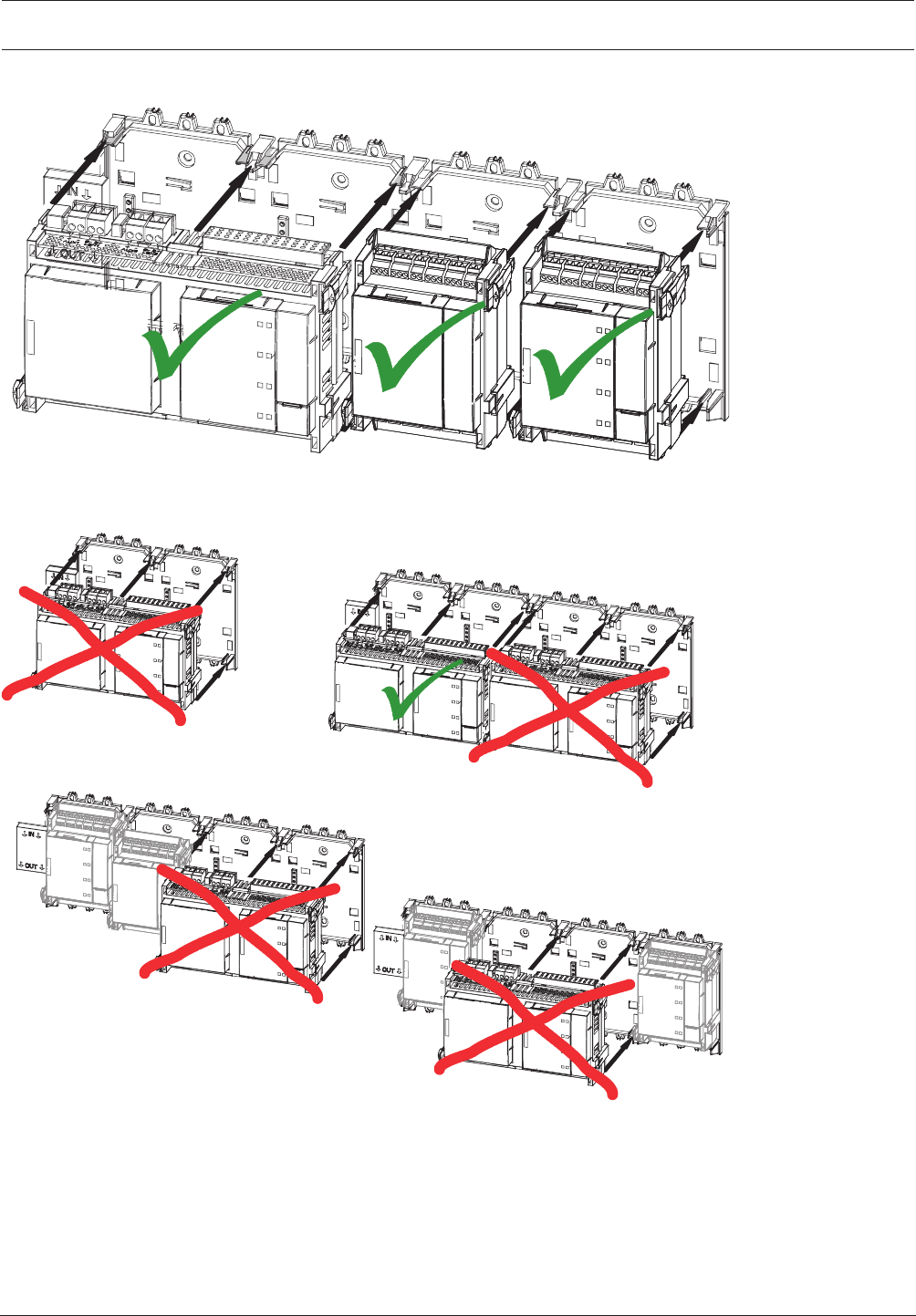
Modular Fire Panel Installation | en 115
Bosch Sicherheitssysteme GmbH System Information 09.2017 | 11.3 | F.01U.028.089
Installation in Panel Rail
PRD 0004 A
PRD 0004 A
PRD 0004 A
PRD 0004 A
PRS-0002-C
LSN 1500 A
LSN 1500 A
LSN 1500 A
LSN 1500 A
LSN 1500 A
LSN 1500 A
Figure4.68: LSN1500A - Inserting the module
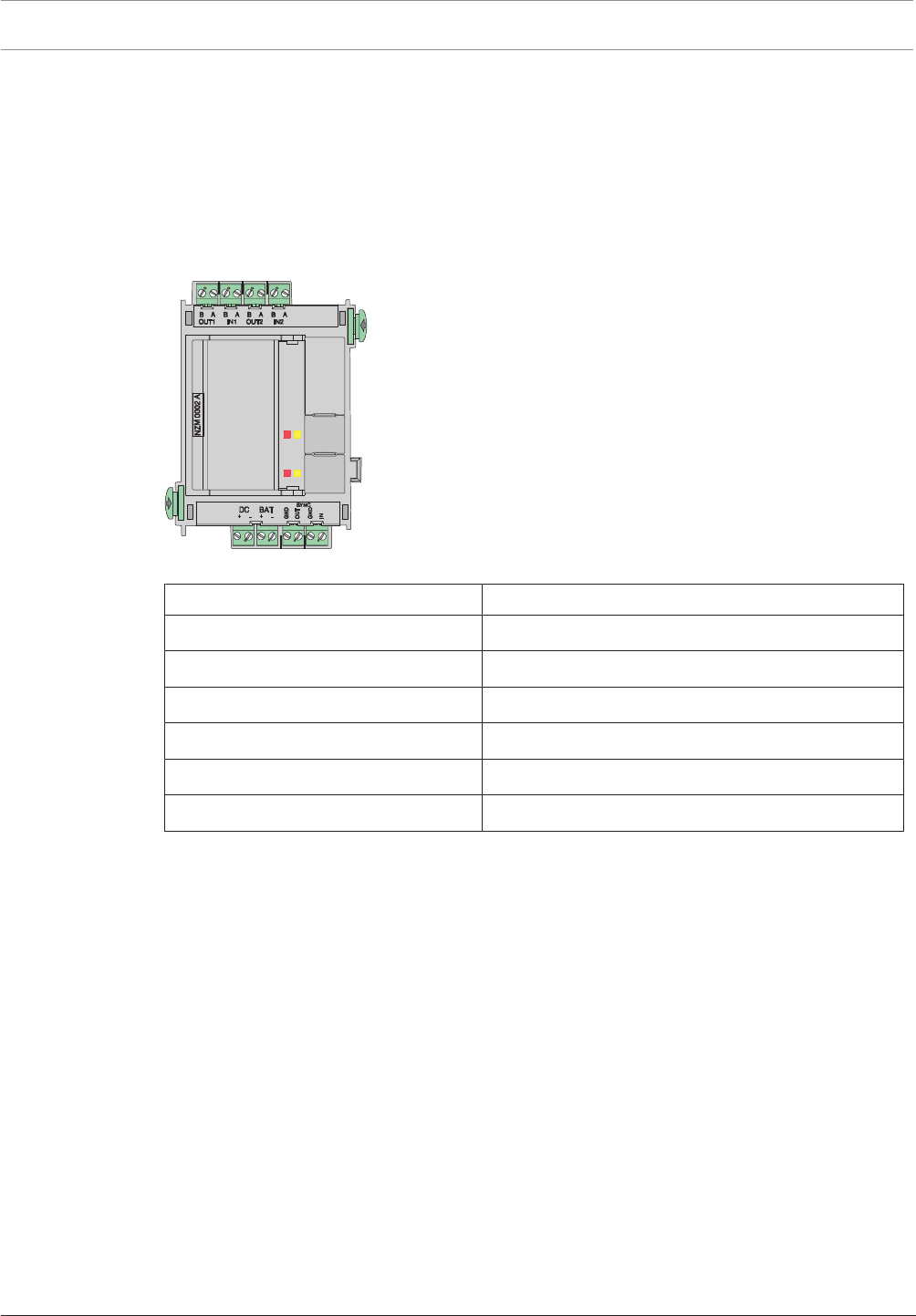
116 en | Installation Modular Fire Panel
09.2017 | 11.3 | F.01U.028.089 System Information Bosch Sicherheitssysteme GmbH
4.9.12 NZM0002A Notification Appliance Zone Module
The NZM0002A Notification Appliance Zone Module provides two monitored primary lines.
This enables the connection of two separate notification appliance lines.
The following can be connected:
– Sounders
– Strobes
– Horns
The operating status of each zone is shown by a red and a yellow status LED.
Figure4.69: NZM0002A Notification Appliance Zone Module
Labeling Connection
B OUT1 | A OUT1 | B IN1 | A IN1 NAC zone1
B OUT2 | A OUT2 | B IN2 | A IN2 NAC zone2
DC + | DC - External power supply
BAT + | BAT - 24VDC input, battery voltage
SYNC GND | SYNC OUT Output synchronization
SYNC GND | SYNC IN Input synchronization
The technical data can be found in NZM0002A Notification Appliance Zone Module, page 155.
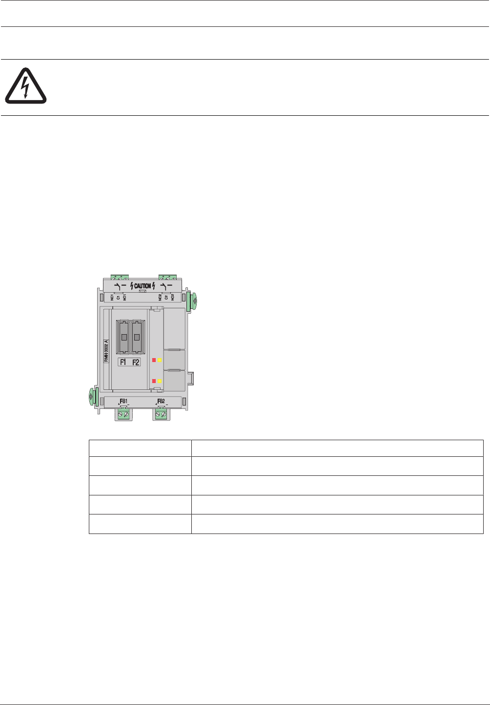
Modular Fire Panel Installation | en 117
Bosch Sicherheitssysteme GmbH System Information 09.2017 | 11.3 | F.01U.028.089
4.9.13 RMH 0002 A Relay Module for Mains Voltage
Danger!
The device contains live components.
Touching live components entails a risk of death or serious injury.
Disconnect the power supply before all installation work.
The module has two changeover contact relays (typeC) for monitored connection of external
elements with feedback, e.g.
– Electromagnetic door holders
– Fans
– Smoke dampers
Each relay has one NO (normally open) and one NC (normally closed) contact and is protected
by a 6.3A fuse.
The outputs are not monitored.
The maximum permissible contact load is 5A at 120V/230VAC and 5A at 30VDC.
The relay module can also be used as an extinguishing system interface in accordance with
VdS2496.
Figure4.70: RMH 0002 A Relay Module for mains voltage
Labeling Connection
NC1 | C1 | NO1 Relay 1
NC2 | C2 | NO2 Relay 2
FB1 + | FB1 - Feedback relay 1
FB2 + | FB2 + Feedback relay 2
The technical data can be found in RMH 0002 A Relay Module for mains voltage, page 155.
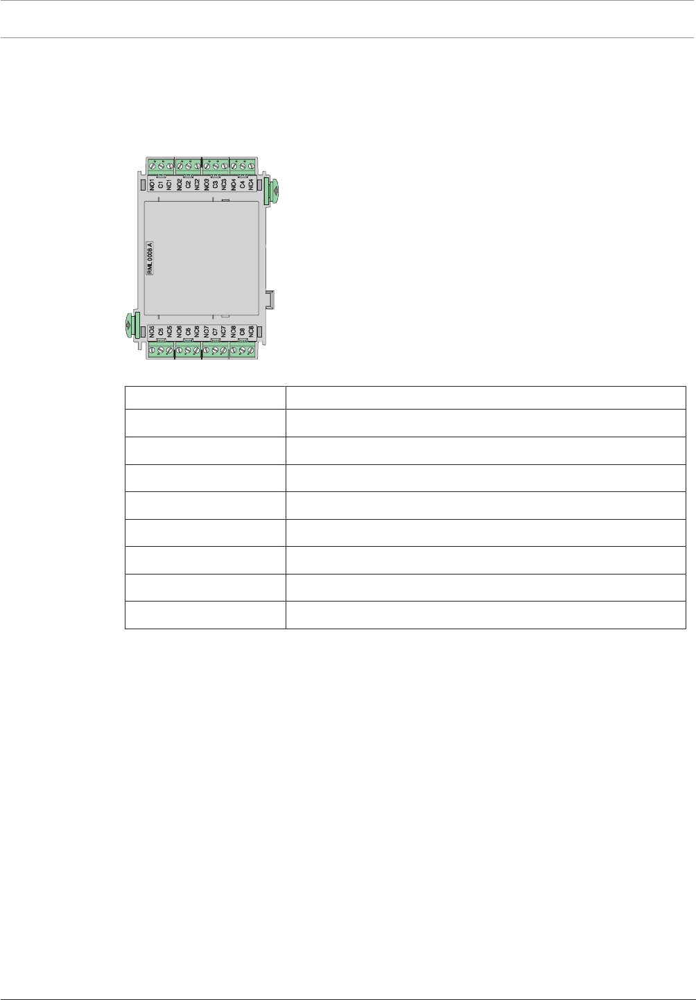
118 en | Installation Modular Fire Panel
09.2017 | 11.3 | F.01U.028.089 System Information Bosch Sicherheitssysteme GmbH
4.9.14 RML 0008 A Relay Module for Low Voltage
Relay module for low voltage with eight changeover relays (type C relays) for connecting
external elements e.g. notification appliances, smoke dampers etc.
Each relay has one NO (normally open) and one NC (normally closed) contact.
The maximum permissible contact load is 30VDC/1A.
Figure4.71: RML 0008 A Relay Module for Low Voltage
Labeling Connection
NO1 | C1 | NC1 Relay 1
NO2 | C2 | NC2 Relay 2
NO3 | C3 | NC3 Relay 3
NO4 | C4 | NC4 Relay 4
NO5 | C5 | NC5 Relay 5
NO6 | C6 | NC6 Relay 6
NO7 | C7 | NC7 Relay 7
NO8 | C8 | NC8 Relay 8
The technical data can be found in RML 0008 A Relay Module for Low Voltage, page 156.
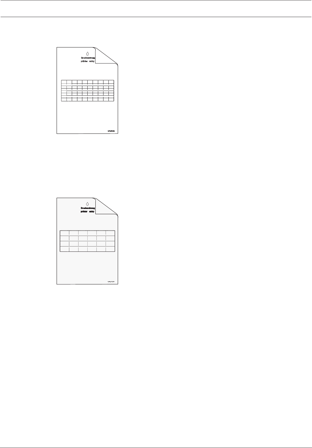
Modular Fire Panel Installation | en 119
Bosch Sicherheitssysteme GmbH System Information 09.2017 | 11.3 | F.01U.028.089
4.9.15 Accessories for Functional Modules
PSL0001A Labeling Strips, Small
210 x 297mm
(DIN A4)
Figure4.72: PSL0001A Labeling Strips, Small
The PSL0001A Labeling Strips, Small can only be used for the ANI0016A Annunciator
Module.
The strips can be individually printed using a standard laser printer. A dot file is included on
the CD supplied with the MPCPanel Controller.
Scope of delivery: 20 sheets of 10 strips.
PSK0001A Labeling Strips, Wide
210 x 297mm
(DIN A4)
Figure4.73: PSK0001A Labeling Strips, Wide
White A4 paper, with pre-punched blank labeling strips for the function keys on the modules.
Each sheet contains six labeling strips.
The PSK0001A Universal Labeling Strips can be used in the following functional modules:
BCM‑0000‑B, CZM0004A, ENO0000B, LSN0300A, LSN1500A, NZM0002A and
RMH0002A.
The strips can be individually printed using a standard laser printer. A dot file is included on
the CD supplied with the MPC Panel Controller.
Scope of delivery: 20 sheets of 6 strips.
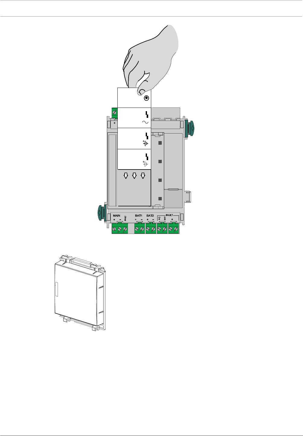
120 en | Installation Modular Fire Panel
09.2017 | 11.3 | F.01U.028.089 System Information Bosch Sicherheitssysteme GmbH
24 V 24 V
MAIN POWER
MAIN POWER
TROUBLE
BATTERY 1
BATTERY 2
TROUBLE
TROUBLE
B-0000-MCB
24 V
Σ
BCM-0000-B
LSN 0300 A
LSN 1500 A
CZM 0004 A
NZM 0000 A
ENO 0000 B
RMH 0002 A
Figure4.74: PSK0001A - Inserting the labeling strip
FDP0001A Dummy Cover Plate
Figure4.75: FDP0001A Dummy Cover Plate
Fit the dummy cover plates on unused module slots in the front panels of the housings.
4.10 Cable Sets
Overview
There are various cable sets available for connecting the central components.
All cable sets are supplied with installation instructions ex works. You can also find the
installation instructions at www.boschsecurity.com by searching for the type designation of
the product. The document numbers of the installation instructions can be found in the footer
on every page of the document.
The table below shows the instructions available.
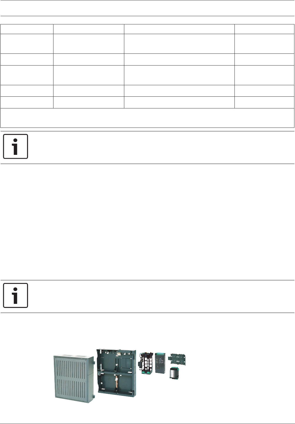
Modular Fire Panel Installation | en 121
Bosch Sicherheitssysteme GmbH System Information 09.2017 | 11.3 | F.01U.028.089
Type designation Connection of ... ... to Document number
CBB 0000 A 1) BCM Battery Controller
Module
Battery pair F.01U.003.099
CPA 0000 A MPC Panel Controller FMA-AT2000-IP/-ISDN/-GSM, ENO0000B F.01U.003.343
CPB 0000 A BCM Battery Controller
Module
UPS Universal Power Supply F.01U.003.098
CPR 0001 A MPC Panel Controller RLE 0000 A Junction Board F.01U.003.342
CRP 0000 A MPC Panel Controller MPC Panel Controller (Redundant) F.01U.003.097
1) Required for power supply in a separate power supply housing. Compared to the enclosed standard cable sets,
this cable set has a longer connecting cable to the battery.
Notice!
In the installation instructions for the CPA0000A Cable Set: Please refer to the programming
instructions for the FMA-AT2000‑IP/-ISDN/-GSM.
4.11 Monitoring auxiliary power according to EN54-13
Auxiliary power supplies to the following modules can be monitored for creeping short circuits
and creeping wire breaks: LSN 300, LSN 1500, and BCM-0000-B (when using FPP-5000-TI13).
A creeping short circuit is detected by these modules. An FPP-5000-TI13 forwards the faults
detected and reported by the BCM-000-B to the panel. Use additional 4-wire end of line
elements to monitor for creeping wire break.
Procedure:
1. Monitor with 4-wire end of line element:
– On stub cabling, terminate the exposed end of an AUX line with an FLM-420-EOL4W
– Insert an FLM-420-EOL4W as the last element of an LSN ring or of a stub
– Use an FLM-320-EOL4W for the conventional zone of a conventional zone module or
a FLM-420-CON/4
2. Activate EN 54-13 compliant operation.
Notice!
According to EN 54-13, no branch wiring (T-tapping) is permitted for auxiliary power supplies.
4.12 FPP‑5000 External Power Supply Unit Kit 24V/6A
The FPP-5000 External Power Supply Unit Kit is designed to provide a universal power supply,
and has space for two 12V/45Ah batteries.
Figure4.76: FPP‑5000 External Power Supply Unit Kit 24V/6A
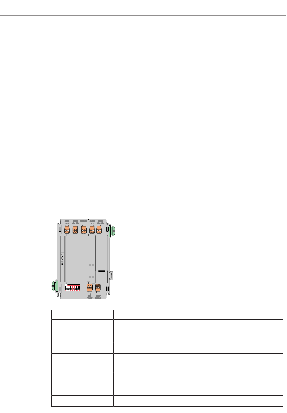
122 en | Installation Modular Fire Panel
09.2017 | 11.3 | F.01U.028.089 System Information Bosch Sicherheitssysteme GmbH
Scope of Delivery
– PMF 0002 A Power Supply Housing Frame Installation medium
– FMH 0000 A Mounting Frame Medium
– Power supply bracket, installed
– UPS 2416 A Universal Power Supply
– PRS-0002-C Panel Rail Short
– BCM-0000-B Battery Controller Module
– Requisite cable sets
Can be Extended with:
– 2 x 12V/45Ah batteries
– FPP‑5000‑TI Trouble Interface or FPP-5000-TI13 LSN Communication Interface
– FPO‑5000‑EB Earth Bar
Notes
– You can find the installation instructions for the FPP-5000 kit at www.boschsecurity.com
by searching for the type designation (document number for installation instructions:
F.01U.005.065).
– The installation dimensions are the same as those for the PMF0004A (see ).
FPP‑5000‑TITrouble Interface
The FPP-5000-TImodule is used in the FPP-5000 External Power Supply Unit with the
BCM-0000-B to transmit faults to the fire panel via the Local Security Network (LSN).
Two independent signal inputs for "battery fault" and "mains current fault" allow a specified
fault indication on the fire panel.
The FPP-5000-TI is connected directly to the LSN bus line and supplied with power via the bus
line.
Figure4.77: FPP‑5000‑TITrouble Interface
Labeling Connection
AUX1 - | AUX1 + Auxiliary power supply, incoming
LSN1 a1 - | LSN1 b1 + LSN in
SHIELD Shield wire
AUX2 - | AUX2 + Auxiliary power supply, outgoing
(support points for looping through)
LSN1 a2 - | LSN1 b2 + LSN outgoing
AC FAULT - | + Input of mains fault
BATT FAULT - | + Input of battery fault
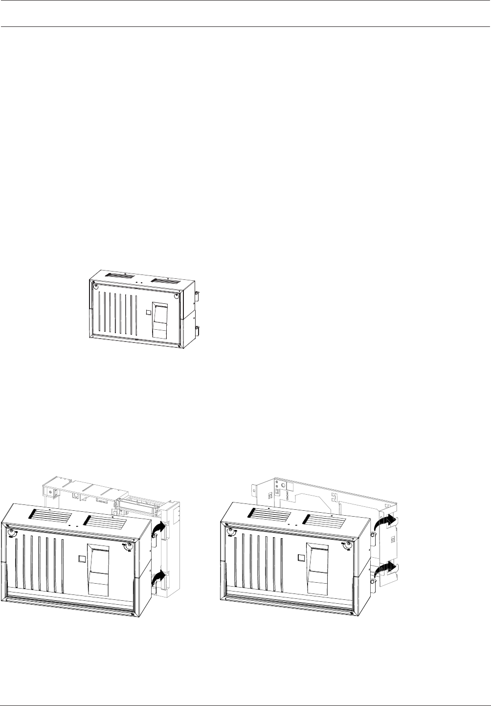
Modular Fire Panel Installation | en 123
Bosch Sicherheitssysteme GmbH System Information 09.2017 | 11.3 | F.01U.028.089
You can find the installation instructions for the FPP‑5000‑TImodule at
www.boschsecurity.com (document number for installation instructions: F.01U.081.396).
The technical data can be found in FPP‑5000‑TITrouble Interface, page 157.
FPP-5000-TI13 Communication Interface
The Communication Interface is an extension for the External Power Supply Unit Kit only. It is
the communication interface between the External Power Supply Unit Kit and the panel, and
transmits the following faults to the panel:
– Mains fault
– Battery fault
– Battery internal resistance fault
– BCM Battery Controller Module fault
– Short 24 V outputs
– Ground fault
Additionally, with the programming software, the switching outputs can be programmed and
the settings for the line monitoring according to EN54-13 can be done.
4.13 THP2020A Thermal Printer
Figure4.78: THP2020A Thermal Printer
Scope of Delivery
– Sheet steel housing, painted
– Thermal printer (installed), with connection cable
– Plastic front panel
– Accessories pack with installation materials
Required for Installation
– FSH0000A Mounting Frame Small, or
– FRS0019A Rack Installation Kit, Small
FSH 0000 A
THP2020 A
FRS 0019 A
THP2020 A
Figure4.79: THP2020A mounting frame/installation kit
General Information
– The following information can be sent to the printer:
– Operating procedures on the panel (e.g. daytime operation)
– Alarm and fault messages
– Plain text; programming is carried out via the programming software FSP-5000-RPS.

124 en | Installation Modular Fire Panel
09.2017 | 11.3 | F.01U.028.089 System Information Bosch Sicherheitssysteme GmbH
– On every printout:
– The current date and the time are specified.
– The most recent event is always at the top
– Entries stored in the history log can also be printed if the operator has the appropriate
operational authorization.
– Always ensure the printer cover panel is closed properly. If the device contact is opened,
incoming messages cannot be printed, even at a later date, as the printer does not have
its own message memory. In this case, the message only appears on the display of the
control panel.
– If the supply of paper is nearing its end, this is indicated by a message on the display of
the control panel. When this message appears, you still have enough paper on the roll to
print approx. 200 lines of text.
Printer Settings using Jumpers
Notes:
– The jumpers BR2, BR3 and BR4 must not be inserted if connecting to the FPA-5000.
– Caution: Inserting jumper BR1 changes the character set from Western to Cyrillic.
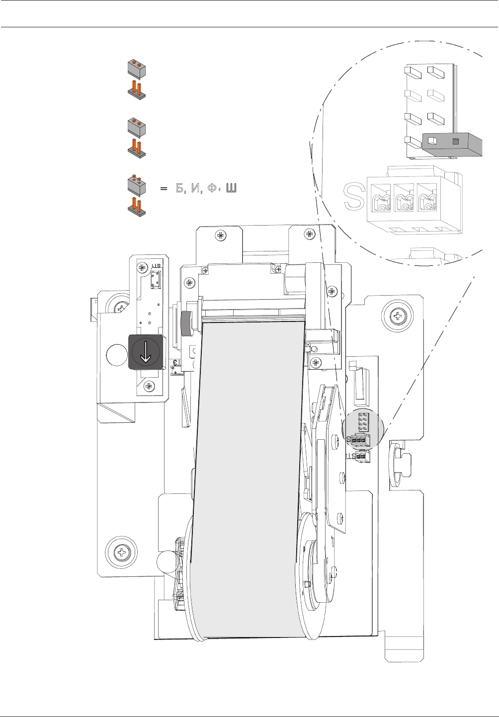
Modular Fire Panel Installation | en 125
Bosch Sicherheitssysteme GmbH System Information 09.2017 | 11.3 | F.01U.028.089
= A, B, C, D (Western)
̨ ̯ ̻ ̿ ̷͚͑͘͘͏͐
BR1
BR2 = 2400 bit/s (UEZ 2000)
=9600 bit/s (FPA-5000)
BR4 = DR 2020
=THP 2020 A (FPA-5000)
BR1
BR2
BR3
BR4
Figure4.80: THP2020A jumpers
Changing the Paper Roll
The paper roll in the printer is changed as follows (see also ):

126 en | Installation Modular Fire Panel
09.2017 | 11.3 | F.01U.028.089 System Information Bosch Sicherheitssysteme GmbH
1. Open the locks and remove the housing front panel.
2. Push down the paper locking lever.
3. Pull out the paper roll unit.
4. Tear off the paper before the last printed message, then hold the paper roll on the
collecting spool and remove the securing disk by pulling it to the left. Remove the printed
paper roll from the collecting spool.
5. Lift out the empty paper roll, making sure that the support pin does not fall out.
6. Remove the empty paper roll and slide a new paper roll onto the support pin.
7. Push the support pin with the new paper roll back between the metal clips.
8. Guide the paper behind the metal pin A and up behind the paper pressure roller B.
9. Pull out the paper up to the paper roll unit and secure the paper with at least one of the
pins of the securing disk. Always slide the securing pins accurately along the guide slots
of the collecting spool.
10. Let the collecting spool fall back into its original position and lift up the paper locking
lever (see arrow).
11. Close the housing front panel and secure with the safety screws.
12. If necessary, tension the paper by pressing the paper feed button.
Notice!
Only use the thermal printer paper specified by the manufacturer
(Bosch product ID 4.998.110.290, pack of 5 rolls).
The paper roll can be changed without turning off the printer.
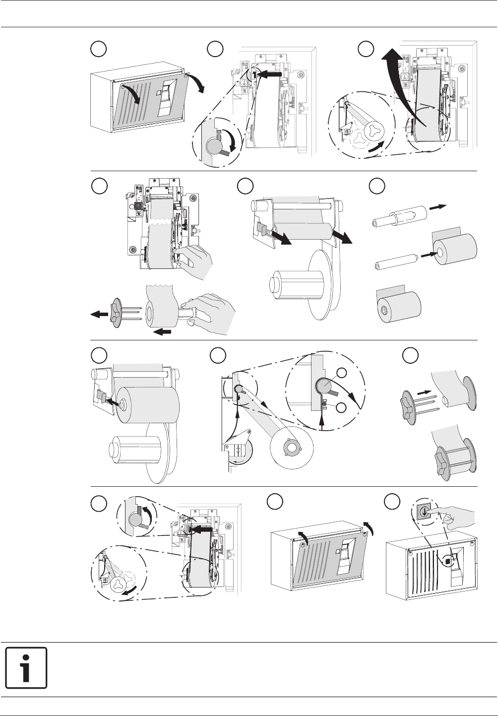
Modular Fire Panel Installation | en 127
Bosch Sicherheitssysteme GmbH System Information 09.2017 | 11.3 | F.01U.028.089
7
11
8
10 12
1 2 3
45 6
9
B
A
Figure4.81: THP2020A - Changing the paper roll
4.14 Remote Keypad
Notice!
Installation must only be carried out by authorized specialist personnel.
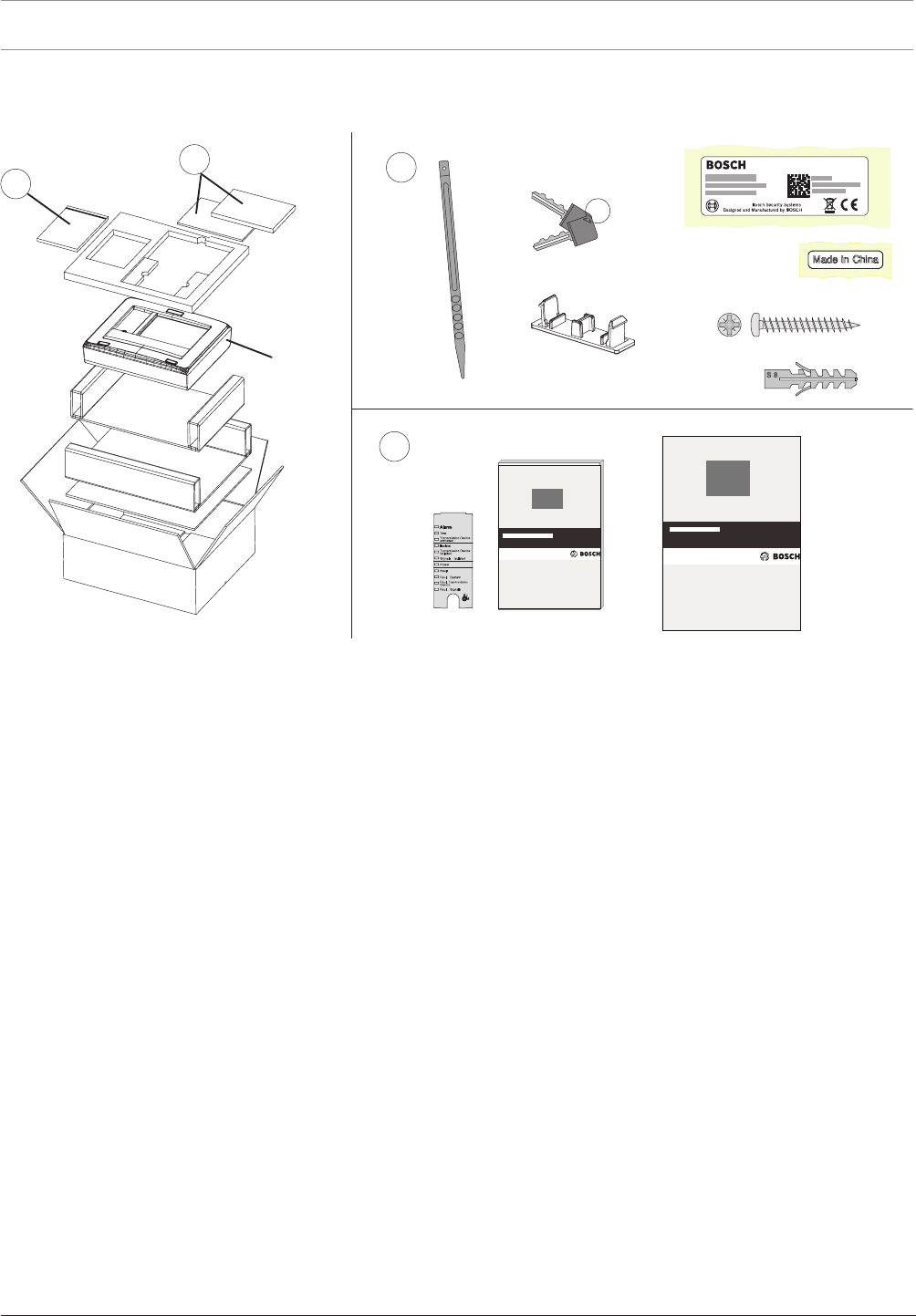
128 en | Installation Modular Fire Panel
09.2017 | 11.3 | F.01U.028.089 System Information Bosch Sicherheitssysteme GmbH
Please refer to the figure for the scope of delivery.
The technical data can be found in Remote Keypad, page 149.
11
2
2
FMR-5000
4x
2x
4x
cs ,QVWDODFQ¯SU¯UXFND
da Installationsvejledning
de Installationsanleitung
el Oδηγϊες σuvαρμολόγησης
en Installation Guide
es Guía de instalación
fr Manuel d’installation
hr 8SXWH]DLQVWDODFLMX
hu 7HOHS¯W«VL¼WPXWDWµ
it Guida di installazione
nl Installatiehandleiding
pl ,QVWUXNFMDLQVWDODF\MQD
pt Guia de Instalação
ro *KLGGHLQVWDODUH
ru ̷͚͕͉͕͙͉͕͖͕͚͙͑͋͘͘D͔͕͉͑H
sv Installationshandledning
sl 1DYRGLOD]DQDPHVWLWHY
tr Kurulum Klavuzu
en Operation Guide
Figure4.82: Remote Keypad - Scope of delivery
Functions
The remote keypad can be used to perform the same operating procedures as the (MPC)
panel itself, enabling a networked system to be operated decentrally.
It has the following functional elements:
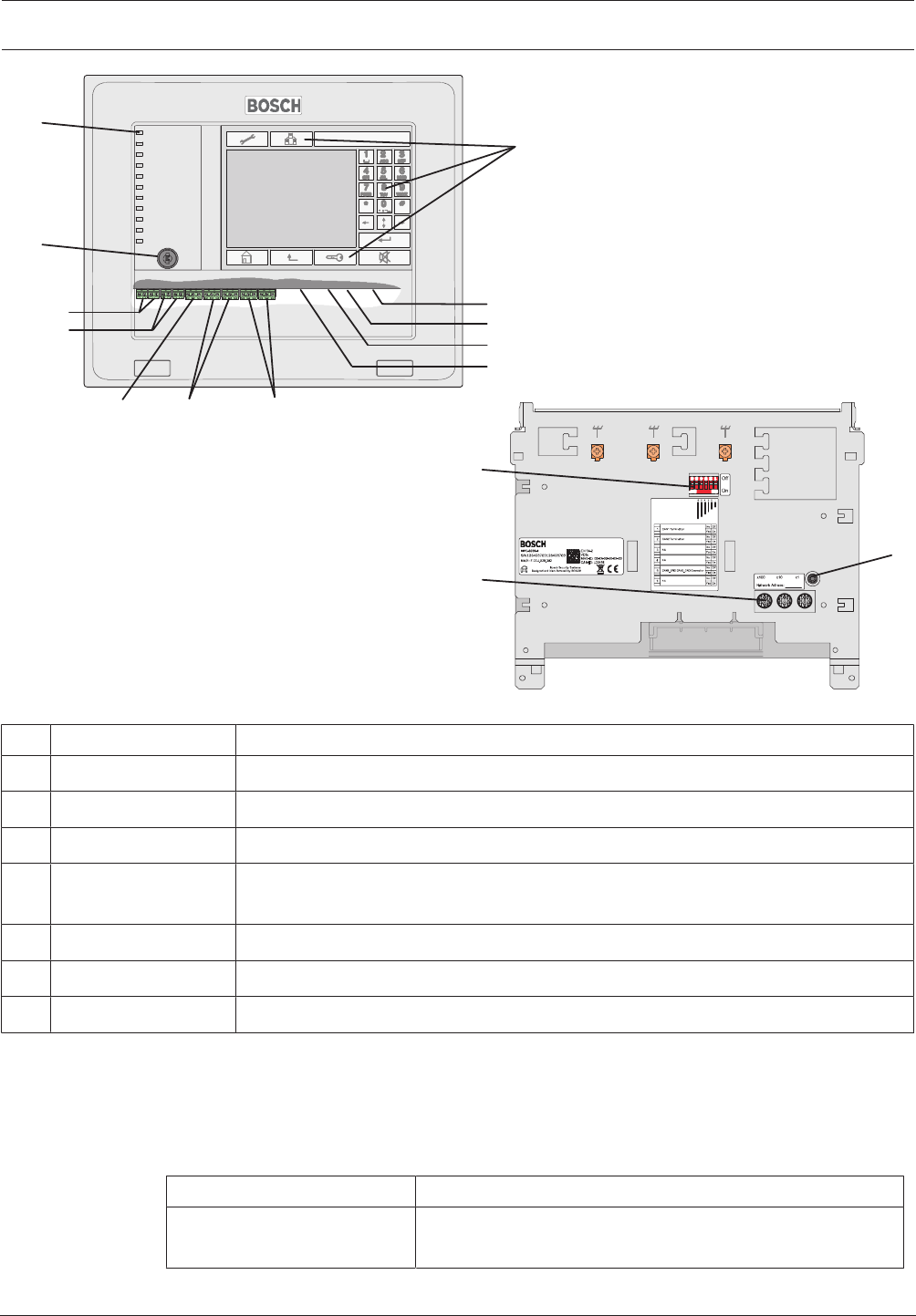
Modular Fire Panel Installation | en 129
Bosch Sicherheitssysteme GmbH System Information 09.2017 | 11.3 | F.01U.028.089
2 x DC1
2 x DC2
RS232
USB Device
USB Host
IN1 / GND / IN2 2 x CAN1 2 x CAN2
3.
5
6
7
1
4
3
2
2 x Ethernet (RJ45)
Figure4.83: Remote Keypad - Functional elements
Pos. Designation Function
1 Touch screen Operation of the networked system using virtual keys and variable display windows
2 Keypad Standard inputs
3 12 LEDs Display operating status
4 Key switch Two switch positions, freely programmable, e.g. for switching between day/night
mode or activating/deactivating local alarms
5 Reboot button Remote keypad hardware reset
6 6-pin DIP switch Configuration setting
7 3 rotary switches Address setting
Note the maximum cable length of 2m for connection to the USB and RS232 interfaces (see
figure).
Information about address setting and configuration in the network can be found in .
Installation
Follow the instructions for the required installation version.
Installation version Installation instructions
Surface wall mounting
(see figure, I)
See steps 1to13 and
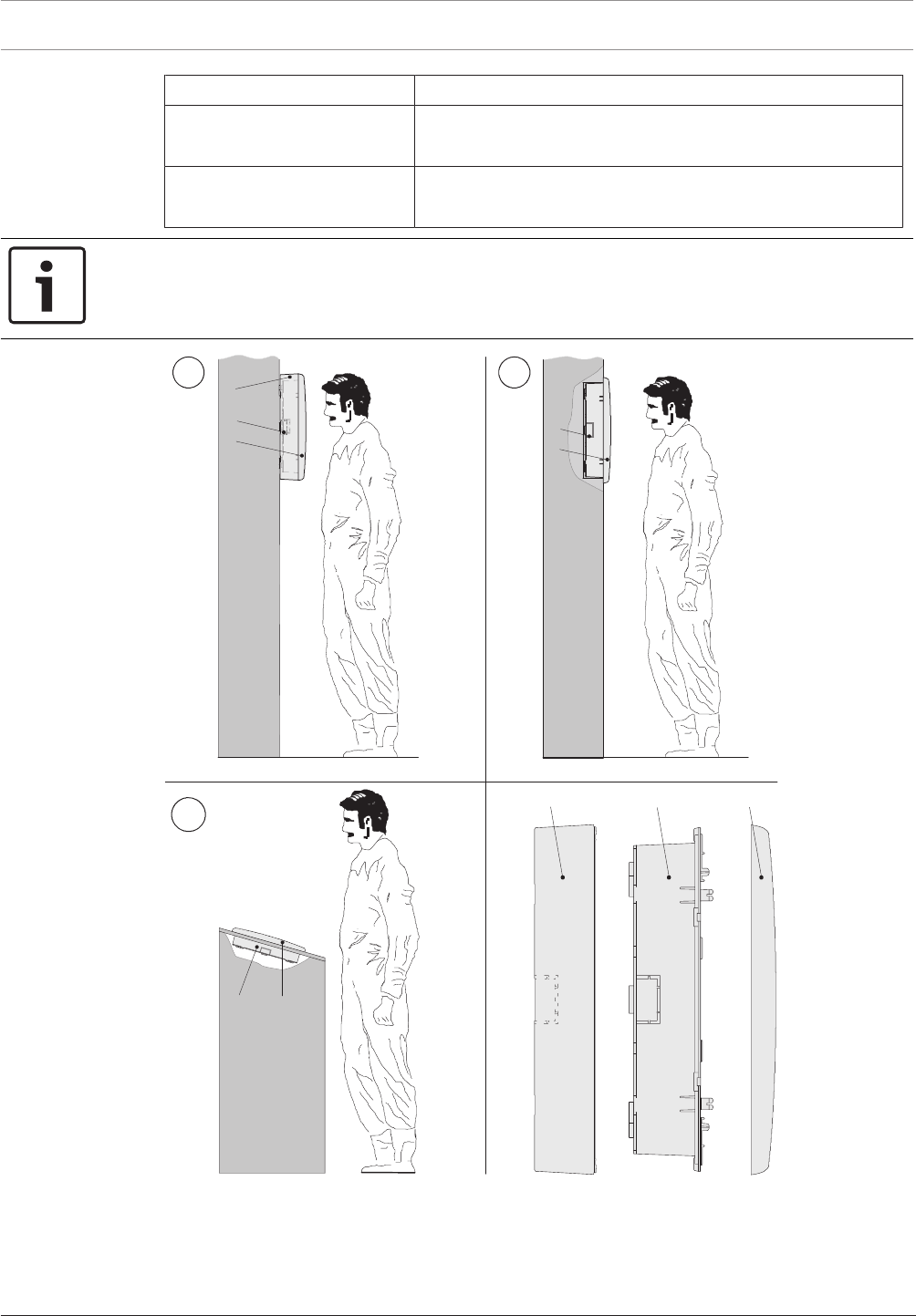
130 en | Installation Modular Fire Panel
09.2017 | 11.3 | F.01U.028.089 System Information Bosch Sicherheitssysteme GmbH
Installation version Installation instructions
Flush wall mounting (see
figure, II)
See steps 1to13 and
Tilted installation
(see figure, III)
See steps 1to13 and
Notice!
Dismantle the operating unit before housing installation. This avoids damage to the touch
screen and makes it easier to screw in the lower fixing screws.
III
III
CBA
CB
C
B
A
C
B
Figure4.84: Remote Keypad installation variations
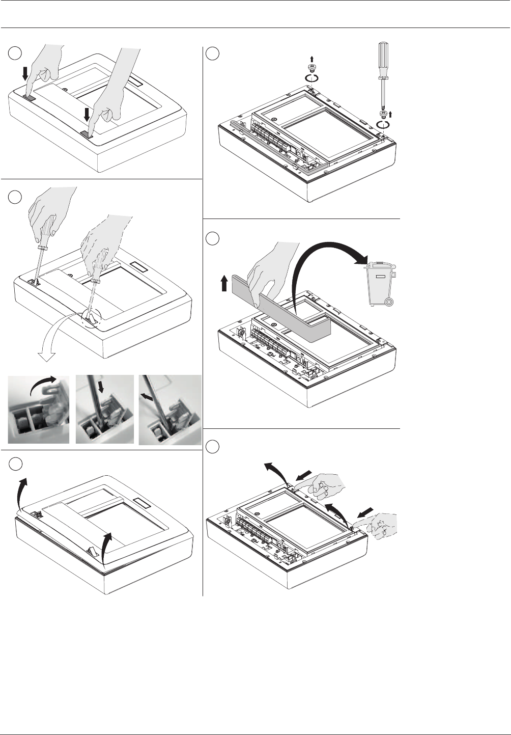
Modular Fire Panel Installation | en 131
Bosch Sicherheitssysteme GmbH System Information 09.2017 | 11.3 | F.01U.028.089
2
14
5
3
2.1 2.2 2.3
PZ2
6
Figure4.85: Remote Keypad installation (1‑6)
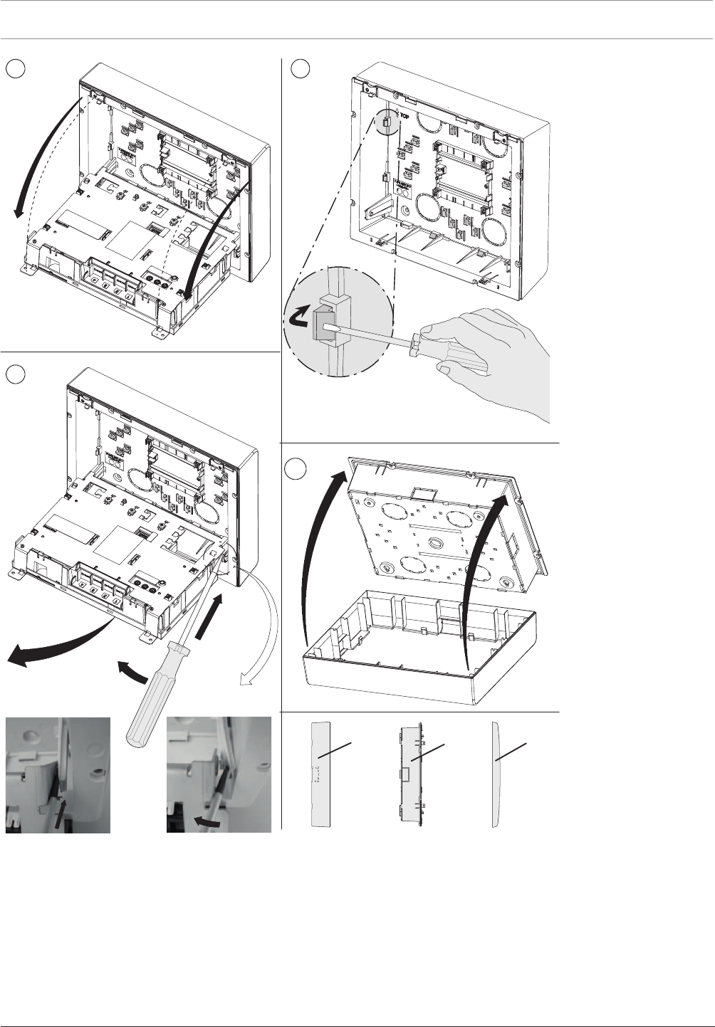
132 en | Installation Modular Fire Panel
09.2017 | 11.3 | F.01U.028.089 System Information Bosch Sicherheitssysteme GmbH
9
7
10
8
8.1 8.2
8.1
8.2
8.3
CBA
8 x
Figure4.86: Remote Keypad installation (7‑10)
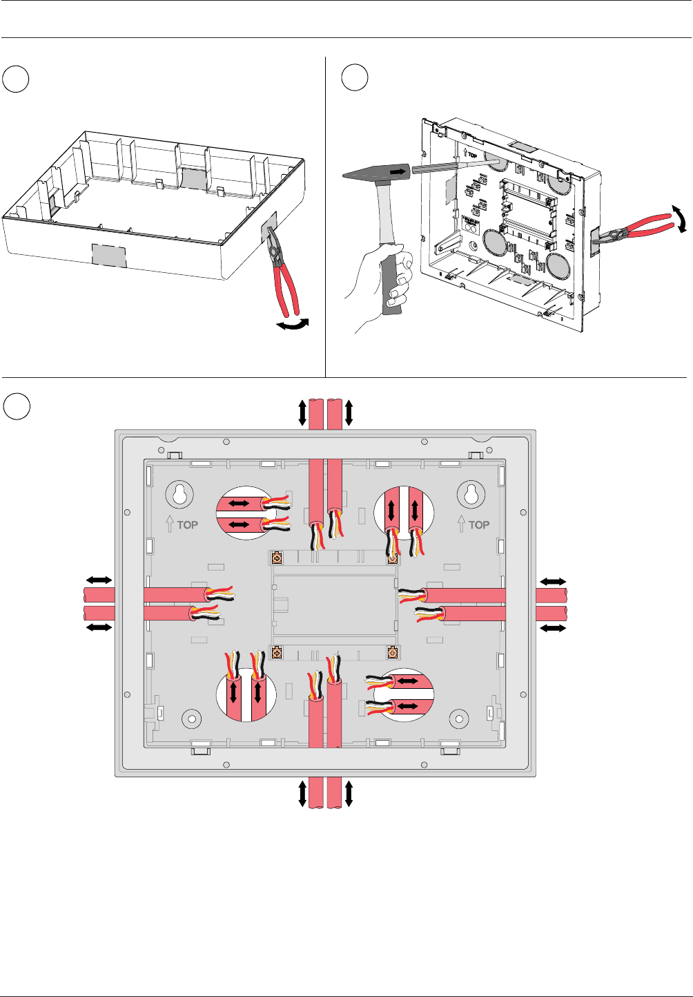
Modular Fire Panel Installation | en 133
Bosch Sicherheitssysteme GmbH System Information 09.2017 | 11.3 | F.01U.028.089
11 12
13
Figure4.87: Remote Keypad installation (11‑13)
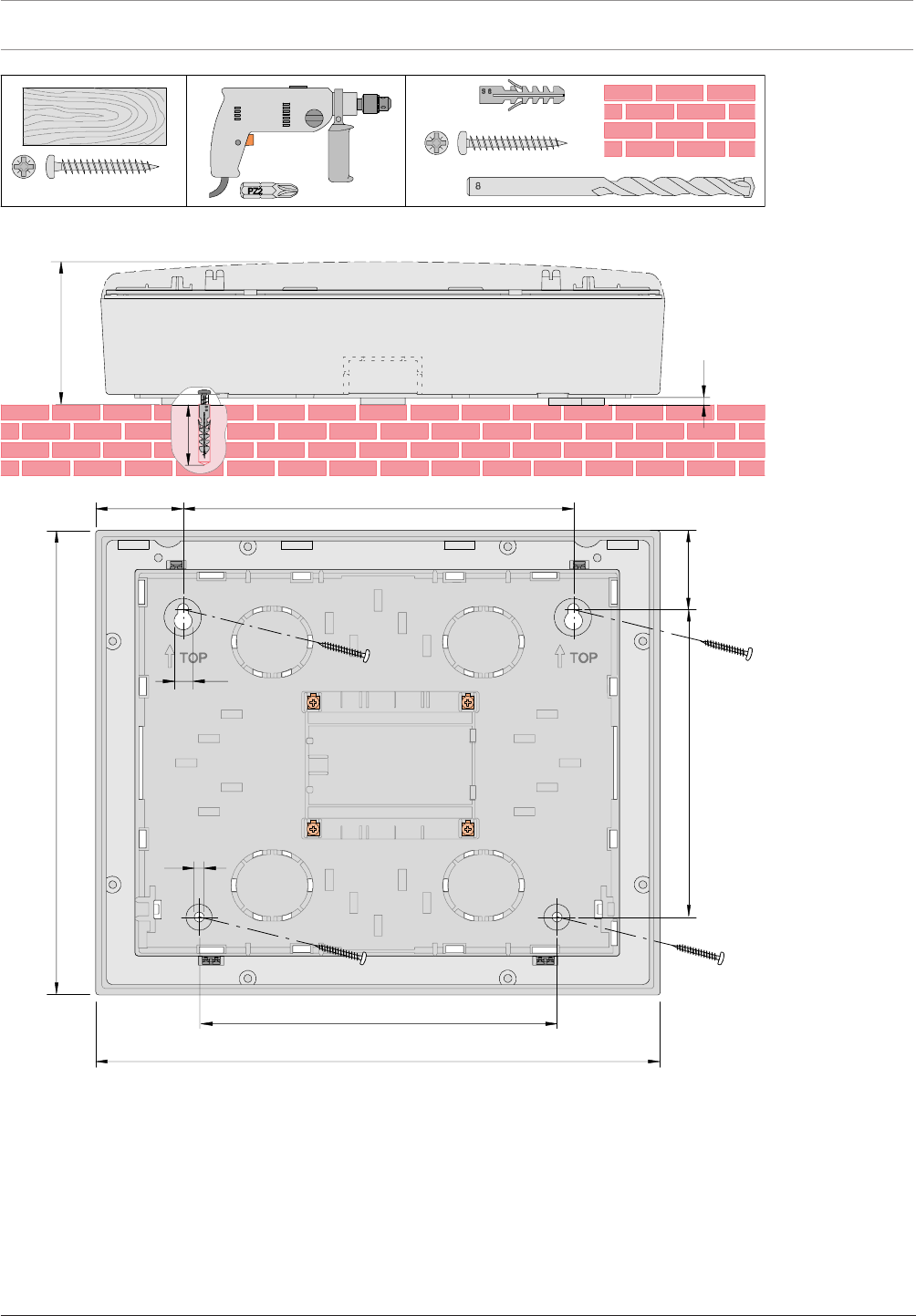
134 en | Installation Modular Fire Panel
09.2017 | 11.3 | F.01U.028.089 System Information Bosch Sicherheitssysteme GmbH
091
340
220
240
082 2,78
54
6
11
4x
(∅ 8 x 40 mm)
∅ 5 x 50 mm
PZ2
S 8
4x
∅ 5 x 50 mmPZ2
4x
∅ 8mm
PZ2
50
05
2,4
Figure4.88: Remote Keypad surface mounting; dimensions in mm
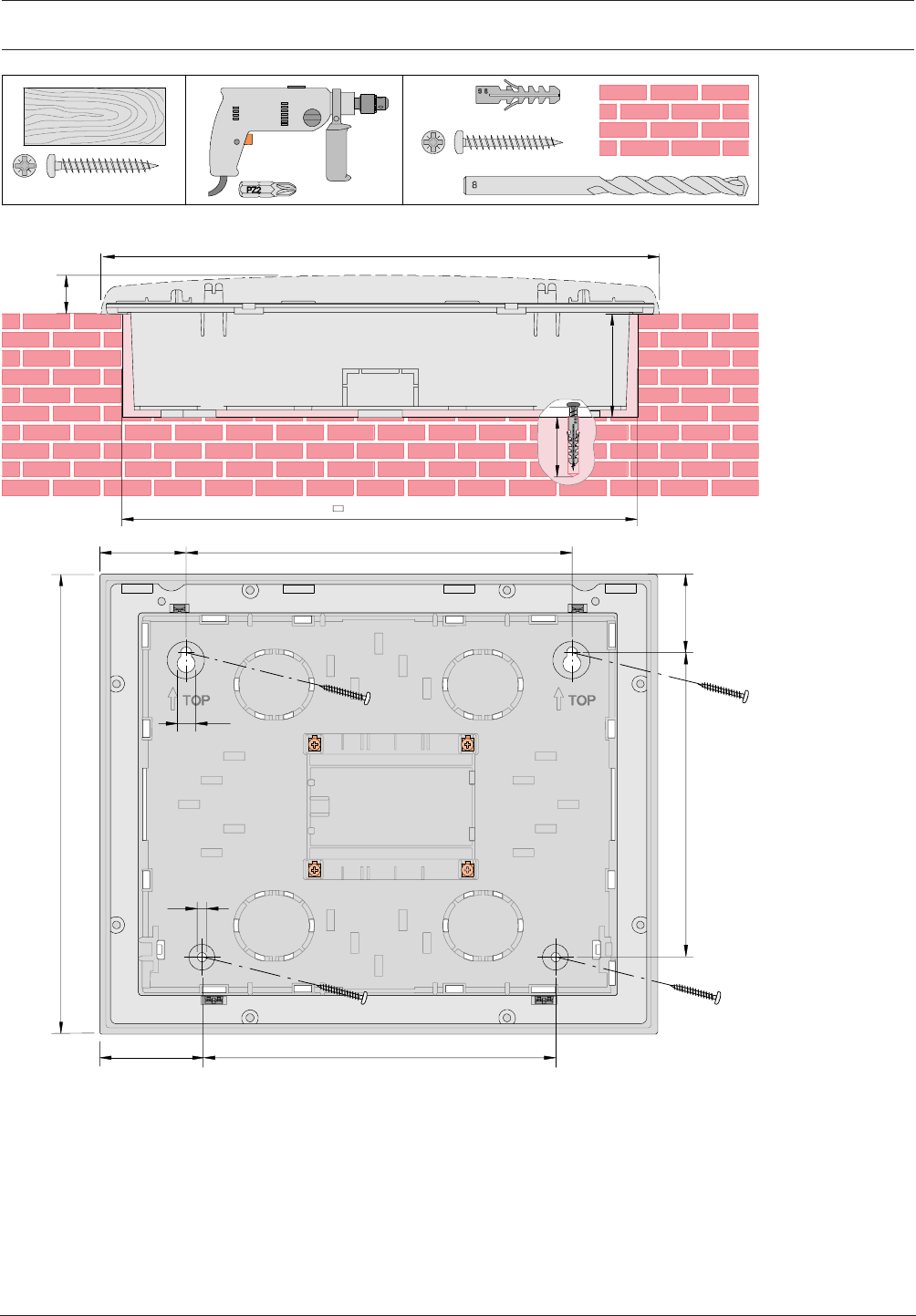
Modular Fire Panel Installation | en 135
Bosch Sicherheitssysteme GmbH System Information 09.2017 | 11.3 | F.01U.028.089
2,42
56
340
250 x 310
091
220
240
0
82
54
6
1
1
50
60
5
0
4x
(∅8 x 40 mm)
∅5 x 50 mm
PZ2
S 8
4x
∅5 x 50 mmPZ2
4x
∅8 mm
PZ2
Figure4.89: Remote Keypad flush mounting; dimensions in mm
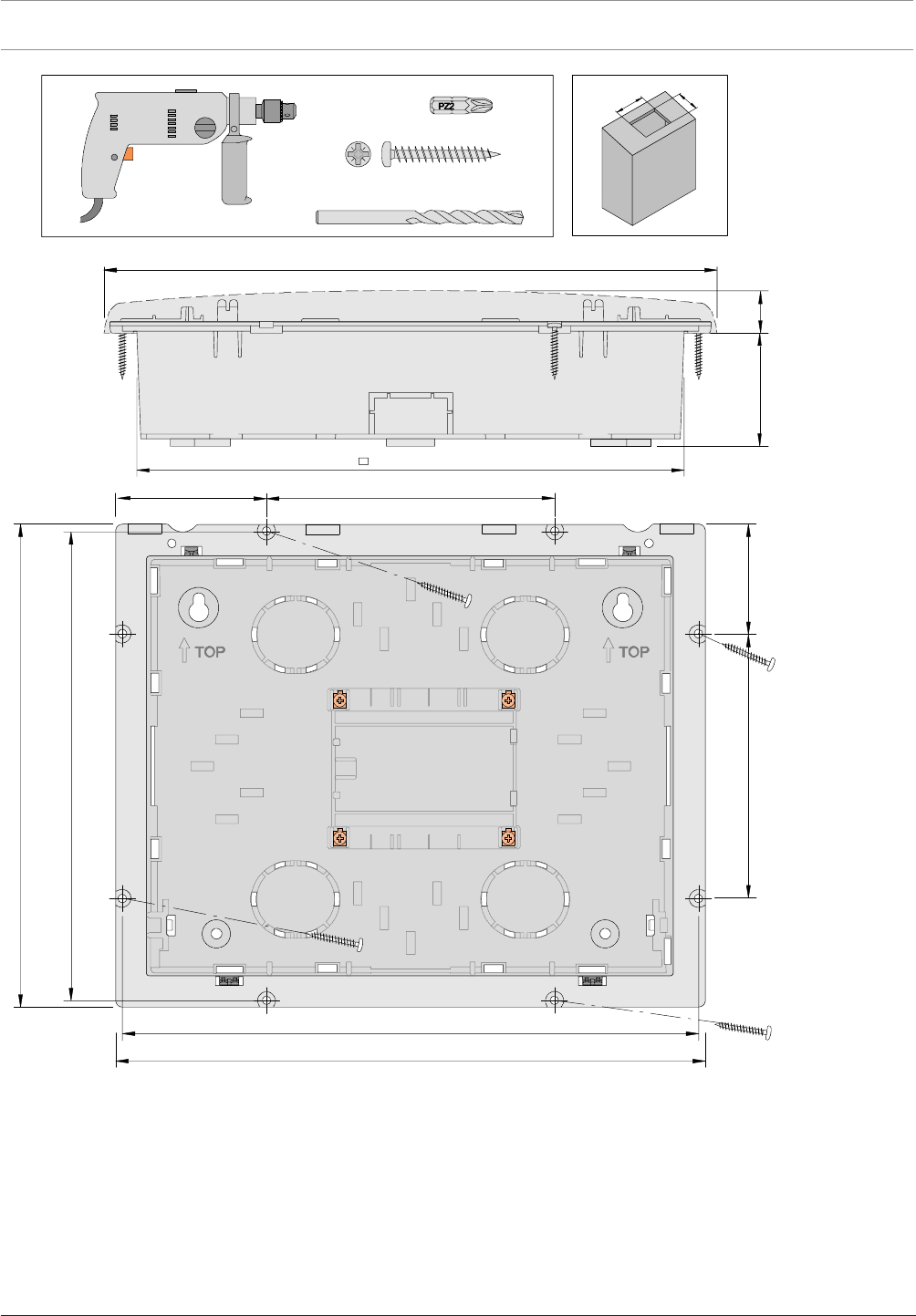
136 en | Installation Modular Fire Panel
09.2017 | 11.3 | F.01U.028.089 System Information Bosch Sicherheitssysteme GmbH
051
334
160
472
2
,4
2
26 36
340
∅5 x 50 mmPZ2
4x
∅2 mm
PZ2
87
244 x 304
326
6
6
2
305
245
Figure4.90: Remote Keypad tilting installation; dimensions in mm
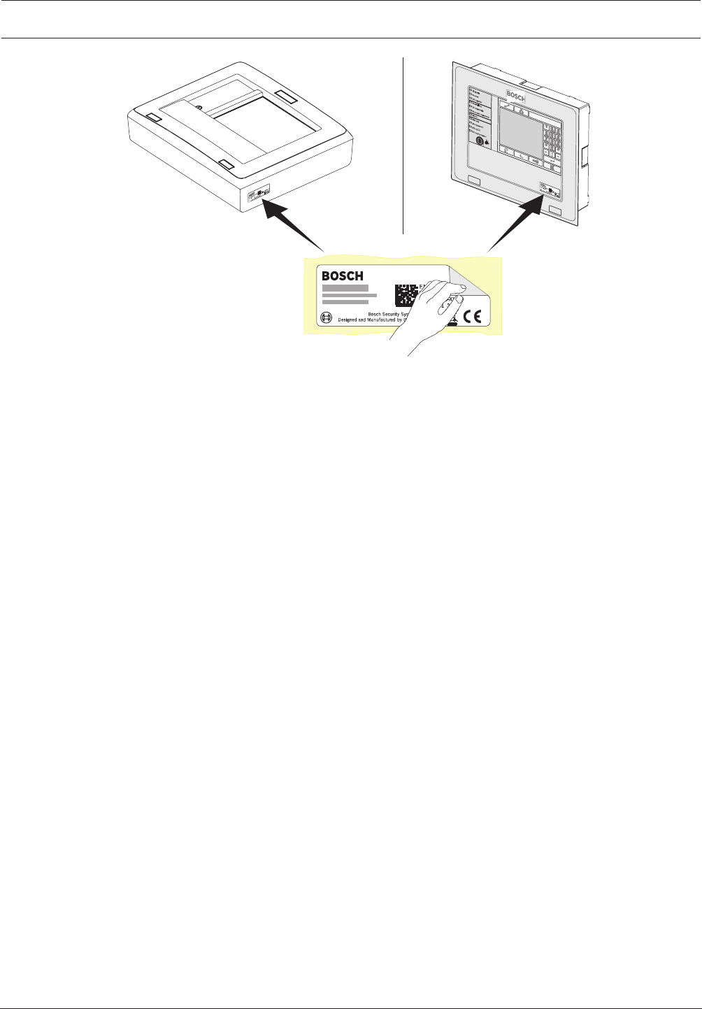
Modular Fire Panel Installation | en 137
Bosch Sicherheitssysteme GmbH System Information 09.2017 | 11.3 | F.01U.028.089
Figure4.91: Remote Keypad sticker
Wiring
1. Place the shield wire on the support point (step1)
2. Secure the cable with cable ties (step1 to 4).
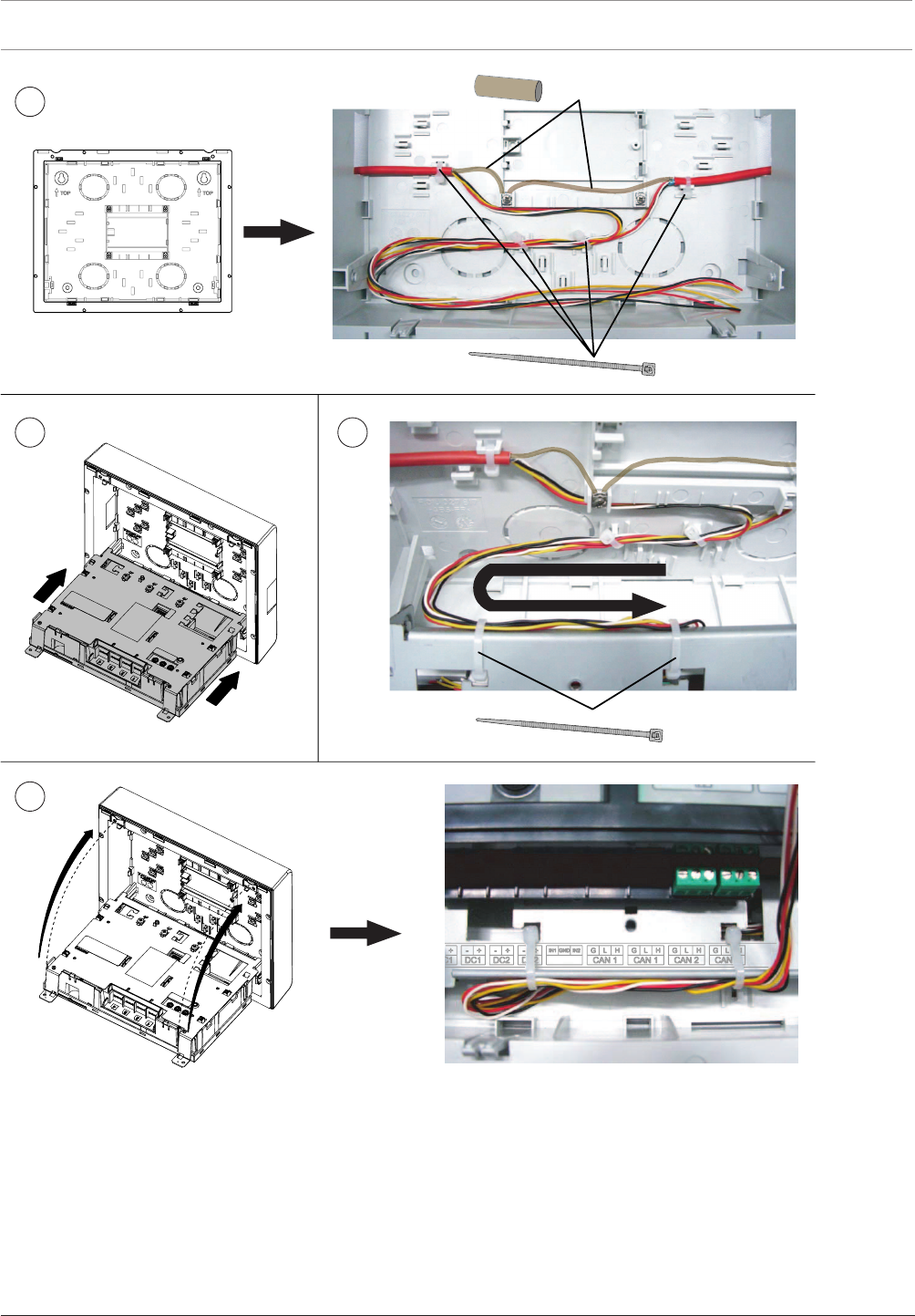
138 en | Installation Modular Fire Panel
09.2017 | 11.3 | F.01U.028.089 System Information Bosch Sicherheitssysteme GmbH
1SHIELD
4x
2x
23
4
Figure4.92: Remote Keypad wiring
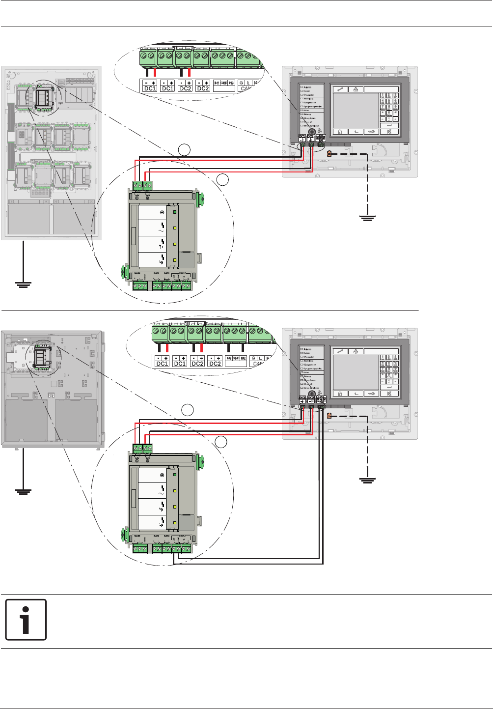
Modular Fire Panel Installation | en 139
Bosch Sicherheitssysteme GmbH System Information 09.2017 | 11.3 | F.01U.028.089
FMR-5000
FPA-5000
FPP-5000
FMR-5000
24V (2,8 A) ⇒ DC2
24V (2,8 A) ⇒ DC1
-AC FAULT ⇒ IN2
-BAT FAULT ⇒ IN1
MAIN POWER
MAIN POWER
TROUBLE
TROUBLE
TROUBLE
BATTERY 1
BATTERY 2
BCM-0000-B
24V (2,8 A) ⇒ DC2
24V (2,8 A) ⇒ DC1
MAIN POWER
MAIN POWER
TROUBLE
TROUBLE
TROUBLE
BATTERY 1
BATTERY 2
BCM-0000-B
12
1
2
Figure4.93: Remote Keypad wiring with BCM-0000-B
Notice!
The value 2.8A must be set in the configuration window of the BCM‑0000‑B in the panel's
programming software.
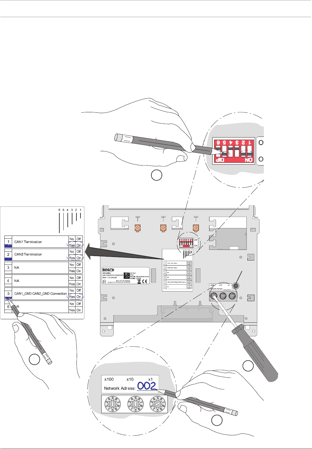
140 en | Installation Modular Fire Panel
09.2017 | 11.3 | F.01U.028.089 System Information Bosch Sicherheitssysteme GmbH
Addressing and Configuration in the Network
The remote keypads are identified in the network by a unique address. This address is set on
the rotary switches and is known as the rotary switch number (RSN) (see the figures in the
circle on the circuit diagrams).
Note the address on the sign above the rotary switches (see , step 2).
Configure the remote keypad using the DIP switches. Mark the selected setting on the sign
below the DIP switches (see , step 4).
Addressing and Configuration of Remote Keypad
1 -- 240
3.
RESET
123456
3
1
2
4
Figure4.94: Addressing and Configuration
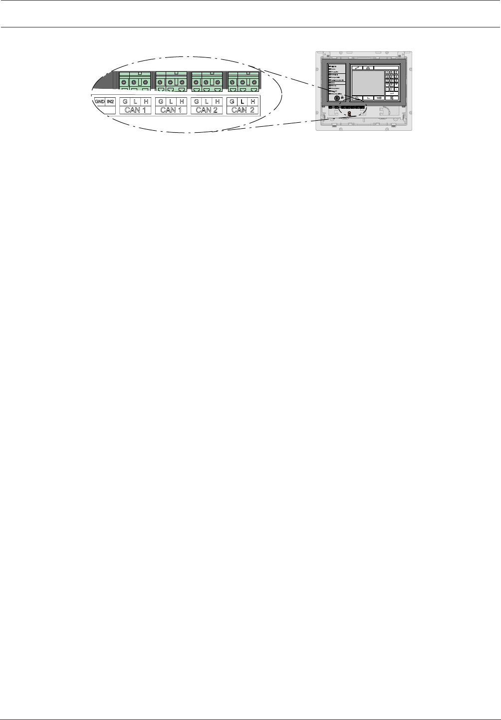
Modular Fire Panel Commissioning | en 141
Bosch Sicherheitssysteme GmbH System Information 09.2017 | 11.3 | F.01U.028.089
FMR-5000
Figure4.95: Network Connections
5 Commissioning
5.1 Notes
– Commissioning and the function test may only be carried out by authorized specialist
personnel.
– Observe all country-specific testing and acceptance regulations.
– A function test must be carried out before commissioning (see Functional Test, page 141).
Bosch Security Systems recommends at least one function test and one visual inspection
per year.
5.2 Documentation
The panel controller is supplied with a CD on which you will find the product documentation
(installation instructions, system description).
The current and full product documentation can also be found on the Internet at
www.boschsecurity.com.
The fire panel is configured on a PC using the FSP-5000-RPS programming software. The
programming software and the associated documentation can also be found on the CD
supplied with the FPA-5000. More recent versions of the software are available on the Internet
for those with access rights.
Information about the programming software is also included in the online help.
5.3 Quick Guide for Commissioning
1. Connect the panel to the power supply.
2. Connect the MPC Panel Controller to the PC (via USB). Make sure that the current
version of the FSP-5000-RPS programming software is installed on your PC.
3. Start the auto-configuration. Edit the configuration according to the requirements of the
fire detection system.
4. Load the configuration to the MPC Panel Controller.
5. Start the walktest.
6. Test the power supply (see Testing the Power Supply, page 142)
7. Check the conventional and LSN functions (see Testing the Conventional and LSN
Functions, page 142).
8. Test all detection points and activations as programmed (see Testing the Addressing/
Activation, page 142).
9. Read out the diagnosis file and save the file as a test log.
5.4 Functional Test
5.4.1 Preparation
Once all components of the fire detection system are installed and wired:
1. Turn on the fire detection system.

142 en | Commissioning Modular Fire Panel
09.2017 | 11.3 | F.01U.028.089 System Information Bosch Sicherheitssysteme GmbH
2. Connect the laptop on which the FSP-5000-RPS programming software is installed to the
fire detection system.
3. Load the configuration.
Now perform the function tests (as described in Testing the Power Supply, page 142 to Testing
the Addressing/Activation, page 142).
5.4.2 Testing the Power Supply
1. Measure the voltage of the batteries.
The target values are12.0V to 14.1V, or 24V to 28.2V.
2. Test the power failure function
Remove the fuse and make sure that the failure of the power supply is indicated on the
display.
Make sure that the time limit for failure of the power supply is set to around 25min (in
the configuration).
3. Restore the power supply.
Once the fire detection system is reconnected to the power supply, it automatically goes
into standby mode, and the power supply failure display disappears.
4. Test the battery failure function:
Remove the cables between the batteries and the BCM module.
Make sure that the time limit for failure of the batteries is set to around 25min (in the
configuration).
Indication of battery failure can be delayed by up to 15min.
5. Reconnect the cables between the batteries and the BCM module.
Once the connection with the batteries has been restored, the battery failure display
must be reset manually.
5.4.3 Testing the Conventional and LSN Functions
1. Testing a conventional/LSN loop:
Disconnect the conventional/LSN loop by detaching the cable connection to the
corresponding functional module.
Failure of the conventional/LSN loop must be indicated on the display.
Restore the connection between the conventional/LSN loop and the corresponding
functional module and reset the error message. Now test all automatic and manual
detectors.
2. Testing a conventional/LSN stub:
Disconnect the conventional/LSN stub by detaching the cable connection to the
corresponding functional module.
Failure of the conventional/LSN stub must be indicated on the display.
Restore the connection between the conventional/LSN stub and the corresponding
functional module and reset the error message. Now test all automatic and manual
detectors.
5.4.4 Testing the Addressing/Activation
1. Test the activation of the transmission devices (TD/DACT/TSN/GSM/X25/X31) by
triggering the corresponding assigned detector.
2. Test the activation of the transmission devices (TD/DACT/TSN/GSM/X25/X31) by
initiating the corresponding fault.
3. Test the activation of extinguishing systems, door controls etc.
4. Test all internal alarm signaling equipment (e.g. audible and visual notification
appliances).
Modular Fire Panel Maintenance and Service | en 143
Bosch Sicherheitssysteme GmbH System Information 09.2017 | 11.3 | F.01U.028.089
6 Maintenance and Service
In Germany, maintenance work and inspection work on security systems are governed by the
regulations of DIN VDE 0833; these regulations stipulate reference to the manufacturer’s
instructions for maintenance intervals.
Notice!
Have maintenance and inspection work carried out regularly by trained, qualified personnel.
Bosch Sicherheitssysteme GmbH recommends a functional and visual inspection at least once
a year.
Danger!
Touching live components can result in electric shock.
Disconnect the power supply to the fire panel before all maintenance or installation work!
6.1 Warranty
Defective modules/devices are exchanged free of charge in the case of a claim under the
warranty.
6.2 Repair
In the event of any defect, the entire module/device is exchanged.
6.3 Disposal
Unusable electrical and electronic devices/modules must not be disposed of
with normal household refuse. They must be disposed of in compliance with
the applicable regulations and directives (e.g. WEEE in Europe).
6.4 Additional Documentation
The installation instructions and operating instructions supplied with the device are available
as PDF files on www.boschsecurity.com.
Additional documents (including the Wiring Guide) are available to those with access rights on
the Extranet on www.boschbuildingsecurity.de/extranet.
Notice!
The hexadecimal error codes can be found on the Extranet (access rights required): LSN
diagnostic data (F.01U.081.090).
7 Technical Data
7.1 System Limits
Panels/remote keypads/OPC server in the network Max. number
Ethernet / CAN loop 32
CAN bus 8

144 en | Technical Data Modular Fire Panel
09.2017 | 11.3 | F.01U.028.089 System Information Bosch Sicherheitssysteme GmbH
LSN elements Max. number
Stand-alone panel 4096
Per network panel 2048
Total network 32768
NAC groups Max. number
NAC groups with more than one FNM-420, per loop 6
Praesideo/PAVIRO Max. number
In CAN network, per panel 1
In Ethernet network, per panel 1
Triggers (each trigger counts as one sounder group) 244
Per fire panel Max. number
Sets, e.g. bypass group 192
Functional modules 46
Printer 4
Alarm counters (external, internal, testing) 3
Entries in the event database 10000
FSP-5000-RPS configuration interfaces (USB, COM) 2
Maximum number of outputs (sounders, controls, etc.) activated in
parallel due to the same event
508
Configuration limits per fire panel (FSP-5000-RPS) Max. number
Timer channels 20
Time control programs 19
Configuration for a Specific Day 365
Permission levels 4
User profiles 200
Sum counters and counters (in total) 60000
Exportable objects including counters in the entire panel cluster
(without pre-defined system counters)
2000
Importable objects including counters (without pre-defined system
counters)
2000
Automatic connections to FMR-5000-C 3
Blocks of State-Dependent Rules (depending on what kind of
activations are possible)
8
Maximum number of rules within a block 254

Modular Fire Panel Technical Data | en 145
Bosch Sicherheitssysteme GmbH System Information 09.2017 | 11.3 | F.01U.028.089
Number of functional modules Max. number
ANI 0016 A 32
BCM-0000-B 8
CZM 0004 A 32
ENO 0000 B 8
FPE-5000-UGM 4
IOP 0008 A 32
IOS 0020 A 4
IOS 0232 A 4
LSN 0300 A 32
LSN 1500 A 11
NZM 0002 A 8
RMH 0002 A 32
RML 0008 A 32
7.2 Power loss of FPA-5000 Components
Component Power loss
ANI 0016 A 0.62W (all LEDs lit)
BCM‑0000‑B – 0.96W (controller + green LED lit)
– 1.44W (per AUX with 1.06A load)
CZM 0004 A – 1.65W (for a line with 100mA load)
– 3.36W (for 4 lines with 100mA load each)
ENO 0000 B – 1.44W (1 relay activated)
– 7.80W (4 relays activated + key deposit heating
active)
FMR-5000-C 5.52 W
FPE-5000-UGM 0.17W
IOP 0008 A 0.24W
IOS 0020 A 0.36W
IOS 0232 A 0.36W
LSN 0300 A – 1.50W (AUX with 490mA load)
– 2.72W (LSN)
LSN 1500 A – 8.00W (AUX)
– 14.70W (LSN with 750mA load)
MPC-xxxx-C 5.40W
NZM 0002 A 0.96W
PRD 0004 A 0.07W

146 en | Technical Data Modular Fire Panel
09.2017 | 11.3 | F.01U.028.089 System Information Bosch Sicherheitssysteme GmbH
Component Power loss
PRS-0002-C 0.07W
RMH 0002 A 1.16W
RML 0008 A 1.04W (all relays activated)
UPS 2416 A 28.00W
7.3 Housing and Accessories
7.3.1 Housings for Frame Installation
Housing material Sheet steel, painted
Housing color Slate gray, RAL7015; front: anthracite gray, RAL7016
Housing type Dimensions (HxWxD) Dimensions including mounting
frame
Weight
CPH 0006 A approx. 638 x 440 x 145mm approx. 663 x 455.5 x 236mm 12.5kg
MPH 0010 A approx. 638 x 440 x 145mm approx. 663 x 455.5 x 236mm 12.5kg
EPH 0012 A approx. 638 x 440 x 145mm approx. 663 x 455.5 x 236mm 13.2kg
PMF 0004 A approx. 502 x 440 x 145mm approx. 527 x 455.5 x 236mm 11.4kg
PSF 0002 A approx. 267 x 440 x 145mm approx. 292 x 455.5 x 236mm 6.4kg
USF 0000 A approx. 267 x 440 x 145mm approx. 292 x 455.5 x 236mm 6.4kg
7.3.2 Housings for Wall Mounting
Housing material Sheet steel, painted
Housing color Slate gray, RAL7015; front: anthracite gray, RAL7016
Housing type Dimensions (HxWxD) Weight
HCP 0006 A approx. 638 x 440 x 149mm 12.5kg
HBC 0010 A approx. 840 x 440 x 149mm 17.0kg
HBE 0012 A approx. 840 x 440 x 149mm 17.0kg
PSB 0004 A approx. 502 x 440 x 149mm 11.4kg
PSS 0002 A approx. 267 x 440 x 149mm 6.4kg
DIB 0000 A approx. 267 x 440 x 149mm 6.4kg
7.3.3 PRS-0002-C Panel Rail Short for 2 Modules
Input voltage 24VDC (20VDC to 30VDC)
Current consumption at 24 V
DC
2.8 mA
Output voltage 5VDC ± 4.5 %/24 V DC
Maximum input current 8 A at 24VDC

Modular Fire Panel Technical Data | en 147
Bosch Sicherheitssysteme GmbH System Information 09.2017 | 11.3 | F.01U.028.089
Maximum output current 1 A at 5VDC
Permissible operating
temperature
-5°C to 50°C (23 °F to 122 °F)
Permissible storage
temperature
-20°C to 60°C (-4 °F to 140 °F)
Material ABS plastic, Polylac PA-766 (UL94V-0)
Color Satin finish, anthracite, RAL7016
Installation of the panel rail is described in Panel Rails, page 78.
7.3.4 PRS0002A Panel Rail Short for 2 Modules (no longer available)
Input voltage 24VDC (20VDC to 30VDC)
Current consumption at
24VDC
7.6mA
Output voltage +5VDC ± 4.5 %/24 V DC
Permissible operating
temperature
-5°C to 50°C
Permissible storage
temperature
-20°C to 60°C
Material and color ABS plastic (UL94V-0), satin finish, anthracite, RAL7016
Space required (H x W x D) approx. 146 x 216 x 35mm
Weight approx. 136g
7.3.5 PRD0004A Panel Rail Long for 4 Modules
Input voltage 24VDC (20VDC to 30VDC)
Current consumption at
24VDC
2.8mA
Output voltage +5VDC ± 4.5%/24VDC
Maximum input current 8A at 24VDC
Maximum output current 1A at 5VDC
Permissible operating
temperature
-5°C to 50°C
Permissible storage
temperature
-20°C to 60°C
Material and color ABS plastic (UL94 V-0), satin finish, anthracite, RAL7016
Space required (H x W x D) approx. 146 x 396 x 35mm
Weight approx. 280g
Installation of the panel rail is described in Panel Rails, page 78.

148 en | Technical Data Modular Fire Panel
09.2017 | 11.3 | F.01U.028.089 System Information Bosch Sicherheitssysteme GmbH
7.3.6 FPO‑5000‑PSB1/FPO‑5000‑PSB‑CH Power Supply Brackets
Permissible operating
temperature
-5°C to 50°C
Permissible storage
temperature
-20°C to 60°C
Weight
– FPO-5000-PSB1 approx. 550g
– FPO-5000-PSB‑CH approx. 395g
Material PA6 plastic, Grilon BSV0 (UL94 V‑0)
Color satin finish, anthracite, RAL 7016
Installation of the devices is described in Power Supply Brackets, page 65.
7.3.7 UPS2416A Universal Power Supply 24V/6A
Input voltage range 100VAC to 240VAC
Input frequency 50Hz to 60Hz
Input current max. 1.95A
Efficiency > 85%
Back-up time >16ms at 115VAC
Output voltage 26VDC to 29VDC
Maximum output current 6A
Maximum power 160W (permanent)
Cooling Ventilation without ventilator
Safety standards IEC60950/EN60950
Permissible operating temperature -5°C to 50°C
Permissible storage temperature -20°C to 60°C
Housing material and color Aluminum, anodized, black satin finish
Space required (H x W x D) approx. 200 x 100 x 40mm
Weight approx. 780g
Installation of the power supply unit is described in UPS2416A Universal Power Supply
24V/6A, page 72.
7.4 Panel Controller and Remote Keypad
7.4.1 MPC
Display element TFT touch screen, 320x240 pixels, 127.5mm x 170mm
active area
Operating elements 22 buttons, 1 key switch, 12 LEDs, 1 reboot button
Interfaces CAN1, CAN2, ETH1, ETH2, USB, RS232

Modular Fire Panel Technical Data | en 149
Bosch Sicherheitssysteme GmbH System Information 09.2017 | 11.3 | F.01U.028.089
Signal inputs IN1/IN2
Max. length of CAN cable for
system networking
Lmax = 1000m, depending on configuration, cable type
and topology
Input voltage 20VDC to 30VDC
Maximum current consumption – Standby mode: 135mA at 24VDC
– In case of alarm: 225mA at 24VDC
Permissible operating temp. -5°C to 50°C
Permissible storage temperature -20°C to 70°C
Space required (H x W x D) 190 x 404 x 60mm
Weight Approx. 2kg
Installation of the device is described in MPCPanel Controller, page 84.
7.4.2 Remote Keypad
Display element TFT touch scree, 320x240 pixels, 127.5mm x 170mm
active area
Operating and display elements 22 buttons, 1 key switch, 12 LEDs, 1 reboot button
Interfaces CAN1, CAN2, ETH1, ETH2, USB, RS232
Signal inputs IN1/IN2
Permissible length of CAN cable
for system networking
Lmax = 1000m, depending on configuration, cable type
and topology
Recommended cable type for
CAN connection
J-Y-ST/Y2x2x0.8
Power supply connections DC1 (power supply),
DC2 (redundant power supply)
Input voltage 12VDC to 30VDC, from FPA‑5000 or FPP‑5000
Maximum power supply line
resistance
18Ω
Maximum current consumption – Standby mode: 140mA at 24VDC
– In case of alarm: 230mA at 24VDC
Permissible operating
temperature
-5°C to 50°C
Permissible storage temperature -20°C to 70°C
Housing material and color ABS plastic, light gray (similar to RAL7035)
Space required (H x W x D) 280 x 340 x 87mm
Weight approx. 3kg
Installation of the device is described in Remote Keypad, page 127.

150 en | Technical Data Modular Fire Panel
09.2017 | 11.3 | F.01U.028.089 System Information Bosch Sicherheitssysteme GmbH
7.4.3 FSP-5000-RPS Programming Software
The following minimum system requirements are defined for the FSP-5000-RPS Programming
Software:
– Operating system: Windows 7 (32bit or 64bit), Windows 10 (32bit or 64bit).
– Hard disk: At least 1GB storage capacity.
– RAM: At least 500MB.
7.5 Functional Modules
The functional modules have the following technical specifications in common:
Permissible operating temperature -5°C to 50°C
Permissible storage temperature -20°C to 60°C
Relative humidity Max. 95% non-condensing
Housing material and color ABS plastic, satin finish, anthracite, RAL7016
Safety standards EN60950
Protection class IP30
Alternative technical data is listed for the individual modules.
7.5.1 ANI0016A Annunciator Module
Display elements 16 red LEDs, 16 yellow LEDs
Input voltage 20VDC to 30VDC/5VDC ± 5%
Maximum current consumption
– Standby mode (all LEDs off) 6mA
– In case of alarm (all LEDs on) 26mA
Space required (H x W x D) approx. 127 x 96 x 60mm
Weight approx. 206g
Installation of the power supply unit is described in ANI0016A Annunciator Module, page 101.
7.5.2 BCM‑0000‑B Battery Controller Module
Input voltage 20.4V to 30V
Current consumption at 23VDC
– Standby operation 25mA
– Fault 40mA
Permissible battery capacities
– with 2batteries 24to26Ah, 36to45Ah
– with 4batteries 48to52Ah, 72to90Ah
Maximum current
– of the module Max. 6A
– to panel rails Max. 6A

Modular Fire Panel Technical Data | en 151
Bosch Sicherheitssysteme GmbH System Information 09.2017 | 11.3 | F.01U.028.089
– for switch outputs Max. 5.6A (2x 2.8A cannot be connected in
parallel)
Maximum load of fault outputs BAT
FAULT, AC FAULT and collective fault
0V/0 - 20mA
Maximum battery resistance (fault
threshold)
430mΩ
Voltage outputs
– 2 switchable outputs +24V (20.4 - 30V), 2.8A, battery buffered
(programmable)
Display and operating elements
– 1 green LED Mains power on
– 3 yellow LEDs Mains fault /fault in battery1/fault in battery2
– 1 button LED test, start charging manually, reset switch
outputs
Space required (H x W x D) approx. 127 x 96 x 60mm
Weight 193g
Permissible operating temperature -5°C to 50°C
Permissible storage temperature -25°C to 85°C
Installation of the power supply unit is described in BCM‑0000‑B Battery Controller Module,
page 101.
7.5.3 CZM0004A 4Zone Conventional Module
Input voltage 20VDC to 30VDC
5VDC ± 5%
Maximum current consumption
– Standby mode (all 4zones) 65mA (at 24VDC)
– In case of alarm (all 4zones) 65mA + 100mA per zone (at 24VDC)
Outputs (OUT1-OUT4)
– Maximum output voltage 20VDC ± 5%
– Maximum output current 100mA ± 10% per zone
– Max. line resistance 2 x 25Ω per zone
Auxiliary power supply (AUX1-AUX4)
– Max. output current (total of all 4
outputs)
230mA
Space required (H x W x D) approx. 127 x 96 x 60mm
Weight without packaging Approx. 135g
Operating and display elements 8LEDs (4x red, alarm/4x yellow, fault)
4keys (LED test)

152 en | Technical Data Modular Fire Panel
09.2017 | 11.3 | F.01U.028.089 System Information Bosch Sicherheitssysteme GmbH
Installation of the power supply unit is described in CZM0004A 4Zone Conventional Module,
page 107.
7.5.4 ENO0000B Fire Service Interface Module
Operating and display elements 2 LEDs (1x red, 1x yellow)/1 button (LED
test)
Input voltage 20VDC to 30VDC
Current consumption
– In standby 25mA
– All relays tripped 60mA
– Key deposit heating additional 240mA
Permissible relay contact load 1A/30V
Space required (H x W x D) approx. 127 x 96 x 60mm
Weight approx. 150g
Installation of the power supply unit is described in ENO0000B Fire Service Interface Module,
page 107.
7.5.5 FPE‑5000‑UGM Interface Module
Operating and display elements 4 two color LEDs (green = transmission / yellow
= fault), 1 button (LED test)
Input voltage 20VDC to 30VDC/5VDC ± 5%
Maximum cable length 1000m
Maximum line resistance 70Ω
Transmission rate 9600bit/s at 1000m to 38400bit/s at 200m
Maximum current consumption
– Standby operation 7mA (at 24V)
– One transmission path active 10mA (at 24V)
– Both transmission paths active 13mA (at 24V)
Space required (H x W x D) approx. 110 x 90 x 60mm
Weight approx. 150g
Installation of the power supply unit is described in FPE‑5000‑UGM Interface Module, page 109.
7.5.6 IOP0008A Input/Output Module
Input voltage 20VDC to 30VDC/5VDC ± 5%
Maximum current consumption 15mA at 24VDC
Maximum switch-on current 700mA (short-circuit protected, Imax = 1.5A)
Maximum cable length 3m
Space required (H x W x D) approx. 127 x 96 x 60mm
Modular Fire Panel Technical Data | en 153
Bosch Sicherheitssysteme GmbH System Information 09.2017 | 11.3 | F.01U.028.089
Weight approx. 150g
Installation of the power supply unit is described in IOP0008A Input/Output Module, page 110.
7.5.7 IOS0020A 20mA Communication Module
Input voltage 20VDC to 30VDC/5VDC ± 5%
Maximum current consumption 15mA at 24VDC
Maximum output current 1.3A at 24VDC resistive
Maximum cable lengths – S1: 1000m
– S20: 1000m
– RS232: 3m
Space required (H x W x D) approx. 127 x 96 x 60mm
Weight approx. 175g
Installation of the power supply unit is described in IOS0020A 20mA Communication Module,
page 111.
7.5.8 IOS0232A RS232 Communication Module
Input voltage 20VDC to 30VDC/5VDC ± 5%
Maximum current consumption 15mA at 24VDC
Maximum cable length 3m per interface
Space required (H x W x D) approx. 127 x 96 x 60mm
Weight approx. 180g
Installation of the power supply unit is described in IOS0232A RS232 Communication Module,
page 112.
7.5.9 LSN0300A LSNimprovedModule 300mA
Operating and display elements 2 LEDs (1xred, alarm/ 1xyellow, fault)
1 button (LED test)
Input voltage 20VDC to 30VDC/5VDC ± 5%
Output voltage
– LSN standby voltage 30 ± 1.0VDC
– LSN transmission voltage 30 ± 1.0VDC + 1.6 ± 0.15VDC (voltage range)
– Auxiliary supply AUX 28 ± 1.0VDC
Maximum current consumption 1750mA at 24VDC
Nominal current consumption
– Module 39mA at 24VDC
– LSN 1.7x current consumption of the LSN elements
– AUX 1.2x auxiliary supply AUX

154 en | Technical Data Modular Fire Panel
09.2017 | 11.3 | F.01U.028.089 System Information Bosch Sicherheitssysteme GmbH
Cable length max. 1600m, depending on configuration and cable
type
Number of LSN elements max. 127 LSN classic elements
max. 254 LSN improved elements
LSN line current max. 300mA, depending on configuration and cable
type
Auxiliary supply AUX
(28VDC)
max. 500mA for an LSN loop (ERT technology) or 2x
max. 500mA with 2 stubs
Space required (H x W x D) approx. 127 x 96 x 60mm
Weight approx. 225g
Installation of the power supply unit is described in LSN0300A LSNimprovedModule 300mA,
page 113.
7.5.10 LSN1500A LSN improved Module 1500mA
Operating and display elements 2 LEDs (1xred, alarm/1xyellow, fault)
1 button (LED test)
Input voltage 20VDC to 30VDC/5VDC ± 5%
Output voltage
– LSN 30 ± 0.85VDC
– Auxiliary supply AUX 28 ± 1.0VDC
Maximum current consumption 4010mA at 24VDC
Nominal current consumption
– Module 260mA at 24VDC
– LSN 1.7x current consumption of the LSN elements
– AUX 1.2x auxiliary supply AUX
Cable length max. 3000m, depending on configuration and cable type
Number of LSN elements Max. 127 LSN classic elements
Max. 254 LSN improved elements
LSN line current
– Standby max. 750mA, depending on configuration and cable type
– Alarm max. 1500mA, depending on configuration and cable
type
max. 300mA when connecting LSN classic elements
Auxiliary supply AUX
(28VDC)
max. 500mA for an LSN loop (ERT technology) or 2x
max. 500mA with 2 stubs
Space required (H x W x D) approx. 127 x 190 x 60mm
Weight approx. 440g

Modular Fire Panel Technical Data | en 155
Bosch Sicherheitssysteme GmbH System Information 09.2017 | 11.3 | F.01U.028.089
Installation of the power supply unit is described in LSN1500A LSN improved Module
1500mA, page 114.
7.5.11 NZM0002A Notification Appliance Zone Module
Operating and display elements 4 LEDs (2xred, alarm/2xyellow, fault)
2 buttons (LED test)
Input voltage 20VDC to 30VDC/5VDC ± 5%
Maximum current consumption
– Standby mode (both zones) 40mA
– In case of alarms (both zones) 65mA + 500mA per notification appliance
Maximum output voltage 29.5VDC
Maximum output current
– For supply via panel rail 500mA per notification appliance (in case of
alarm)
– For external power supply 3A per notification appliance (in case of
alarm)
Space required (H x W x D) approx. 127 x 96 x 60mm
Weight Approx. 135g
Installation of the power supply unit is described in NZM0002A Notification Appliance Zone
Module, page 116.
7.5.12 RMH 0002 A Relay Module for mains voltage
Operating and display elements 4 LEDs (2xred, alarm/2xyellow, fault)
2buttons (each on/off)
Fuses F1 = T6.3A, F2 = T6.3A
Input voltage 20VDC to 30VDC/5VDC ± 5%
Feedback current max. 8.5mA per feedback output
Feedback voltage max. 30VDC
Maximum current consumption
– Standby operation 10mA
– Both relays tripped 50mA
Maximum contact load 5A at 120V/230VAC or 5A at 30VDC
(resistive)
Maximum line resistance of feedback lines 2x25Ω
Space required (H x W x D) approx. 127 x 96 x 60mm
Weight Approx. 135g
Installation of the power supply unit is described in RMH 0002 A Relay Module for Mains
Voltage, page 117.

156 en | Technical Data Modular Fire Panel
09.2017 | 11.3 | F.01U.028.089 System Information Bosch Sicherheitssysteme GmbH
7.5.13 RML 0008 A Relay Module for Low Voltage
Input voltage 20VDC to 30VDC/5VDC ± 5%
Maximum current consumption
– Standby operation 4mA
– All relays tripped 68mA
Maximum contact load 1A at 30VDC resistive
Space required (H x W x D) approx. 127 x 96 x 60mm
Weight approx. 150g
Installation of the power supply unit is described in RML 0008 A Relay Module for Low Voltage,
page 118.
7.6 FPP‑5000 External Power Supply Unit Kit 24V/6A
7.6.1 FPP‑5000 Kit
Input voltage range 100VAC to 240VAC
Input frequency range 50Hz to 60Hz
Efficiency > 85%
Back-up time >100ms at 230VAC
Output voltage
– With mains supply 26 - 29VDC (depending on temperature),
26.8VDC nominal (at 40°C)
– With battery supply 21 - 23VDC
Maximum output current 6A
Max. output 160W (permanent)
Maximum load of fault outputs BATFAULT,
ACFAULT, and collective fault
0V/0 - 20mA
2 voltage outputs, switchable +24V/2.8A (20.4-30V), battery buffered
Housing material Sheet steel, painted
Housing color Slate gray, RAL7015
Front: anthracite gray, RAL7016
Dimensions, installed (H x W x D) approx. 527 x 456 x 326mm
Protection class as per EN 60950 Class I equipment
Permissible operating temperature -5°C to 50°C
Permissible storage temperature -20°C to 60°C
Relative humidity Max. 95% non-condensing
Cooling Ventilation without ventilator

Modular Fire Panel Appendix | en 157
Bosch Sicherheitssysteme GmbH System Information 09.2017 | 11.3 | F.01U.028.089
Installation of the power supply unit is described in RMH 0002 A Relay Module for Mains
Voltage, page 117.
7.6.2 FPP‑5000‑TITrouble Interface
Input voltage 15VDC to 30VDC
Maximum current consumption 1.15mA (at 24V), from LSN
Protection class (IEC60529) IP20
Addressing using eight DIP switches
Space required (H x W x D) approx. 127 x 96 x 60mm
The module is described in FPP‑5000 External Power Supply Unit Kit 24V/6A, page 121.
7.6.3 FPP‑5000‑TI13 Communication Interface
Input voltage 15VDC to 33VDC
Current consumption
– From panel rail at 24VDC
– From LSN
– 13.2mA
– 3.25mA
Protection class (IEC60529) IP20
Space required (H x W x D) approx. 127 x 96 x 60mm
The module is described in FPP‑5000 External Power Supply Unit Kit 24V/6A, page 121.
8 Appendix
8.1 Options with requirements under EN 54‑2:1997/A1:2006
The FPA-5000 provides the following options with requirements under EN 54‑2:1997/A1:2006:
– Output for activation of fire alarm devices
– Activation of fire alarm transmission equipment
– Output to fire alarm transmission equipment
– Alarm acknowledgement input from fire alarm transmission equipment
– Output for activation of fire protection equipment
– Output type A
– Output type B
– Output type C
– Fault monitoring of fire protection equipment
– Transmission delay
– Dependency of fire detection status on more than one alarm signal
– Type A dependency
– Type B dependency
– Alarm counter
– Fault signal status
– Fault signals from detection points
– Complete failure of power supply
– Output to fault signaling transmission equipment
– Disabled status
– Disabling of addressable points
– Test status

158 en | Appendix Modular Fire Panel
09.2017 | 11.3 | F.01U.028.089 System Information Bosch Sicherheitssysteme GmbH
8.2 Component Overview
8.2.1 Frame Installation Housings, Mounting Frames and Installation Kits
Panel Housings for Frame Installation
Designation Product ID
CPH0006A Modular Panel Housing for 6 Modules, Frame Installation 4.998.137.290
MPH0010A Modular Panel Housing for 10 Modules, Frame Installation 4.998.137.291
Extension Housings for Frame Installation
Designation Product ID
EPH0012A Modular Extension Housing for 12 Modules 4.998.137.292
PMF0004A Power Supply Big, Frame Installation 4.998.137.294
PSF0002A Power Supply Small, Frame Installation 4.998.137.293
USF0000A Universal Housing Small, Frame Installation 4.998.147.119
Mounting Frames
Designation Product ID
FBH0000A Mounting Frame Large 4.998.137.296
FHS0000A Mounting Frame Large with Distributor Rail 4.998.139.490
FMH0000A Mounting Frame Medium 4.998.137.297
FSH0000A Mounting Frame Small 4.998.137.298
48cm (19”) Installation Kits for Frame Installation Housing
Designation Product ID
FRB0019A Installation kit, large, 15 height units 4.998.139.498
FRM0019A Installation kit, medium, 12 height units 4.998.139.499
FRS0019A Installation kit, small, 6 height units 4.998.139.500
8.2.2 Wall Mounting Housings and Installation Kits
Panel Housings for Wall Mounting
Designation Product ID
HBC0010A Modular Panel Housing for 10 Modules 4.998.137.286
HCP0006A Modular Panel Housing for 6 Modules 4.998.137.285
Extension Housings for Wall Mounting
Designation Product ID
DIB0000A Distribution Box 4.998.139.497
HBE0012A Modular Extension Housing for 12 Modules 4.998.137.287
PSB0004A Power Supply 4.998.137.289
PSS0002A Power Supply Small, Frame Installation 4.998.137.288
Modular Fire Panel Appendix | en 159
Bosch Sicherheitssysteme GmbH System Information 09.2017 | 11.3 | F.01U.028.089
48cm (19”) Installation Kit for Wall Mounting Housing
Designation Product ID
FRK0019A Installation kit F.01U.511.304
8.2.3 Accessories for Housing
Front Doors (Transparent Plastic)
Designation Product ID
FDT0000A Front Door Transparent, lock right side 4.998.147.120
FDT0001A Large Front Door Transparent, lock right side 4.998.153.238
FDT0002A Large Front Door Transparent, lock left side 4.998.153.239
FDT0003A Front Door Transparent, lock left side F.01U.508.703
Mounting Plates/Installation Accessories
Designation Product ID
FPO‑5000‑EB Earth Bar F.01U.513.251
HMP0003A Mounting Plate for Mounting Frame F.01U.511.305
RLE0000A Junction Board 4.998.153.241
Mounting Kits for Ethernet switch and media converter
Designation Product ID
FPM-5000-KES Mounting Kit for Ethernet Switch F.01U.266.844
FPM-5000-KMC Mounting Kit for Media Converter F.01U.266.845
8.2.4 Panel Rails
Designation Product ID
PRD0004A Panel Rail Long, for up to 4Modules 4.998.137.280
PRS-0002-C Panel Rail Short, for up to 2Modules F.01U.284.903
8.2.5 Power Supply Units, Power Supply Brackets, Batteries
Designation Product ID
FPP‑5000 External Power Supply Unit Kit F.01U.511.307
FPP‑5000‑TI Trouble Interface for FPP‑5000 F.01U.073.324
FPP‑5000‑TI13 LSN Communication interface for FPP‑5000 F.01U.161.679
UPS2416A Universal Power Supply 24V/6A F.01U.500.367
FPO‑5000‑PSB‑CH Power Supply Bracket F.01U.078.860
FPO‑5000‑PSB1 Power Supply Bracket F.01U.078.858
Battery 12V/28Ah 2.799.502.177
Battery 12V/45Ah 2.799.380.000

160 en | Appendix Modular Fire Panel
09.2017 | 11.3 | F.01U.028.089 System Information Bosch Sicherheitssysteme GmbH
8.2.6 Panel Controller/Remote Keypad
MPC Panel Controllers
Designation Product ID
MPC‑0000-C Panel Controller DE,
Labeling and documentation in German
F.01U.275.048
MPC‑1300-CPanel Controller EN,
Labeling and documentation in English
F.01U.275.049
MPC‑1400-C Panel Controller PT,
Labeling and documentation in Portuguese
F.01U.275.050
MPC‑1500-C Panel Controller CZ,
Labeling and documentation in Czech
F.01U.275.051
MPC-1600-C Panel Controller HU,
Labeling and documentation in Hungarian
F.01U.275.052
MPC-1700-C Panel Controller IT/DE,
Labeling and documentation in Italian/German
F.01U.275.053
MPC‑2000-C Panel Controller ES,
Labeling and documentation in Spanish
F.01U.275.054
MPC‑3000-C Panel Controller PL,
Labeling and documentation in Polish
F.01U.275.055
MPC‑5000-C Panel Controller FR/NL,
Labeling and documentation in French/Dutch
F.01U.275.056
MPC‑6000-C Panel Controller EL,
Labeling and documentation in Greek
F.01U.275.057
MPC‑7000-C Panel Controller RO/EN,
Labeling and documentation in Romanian/English
F.01U.275.058
MPC‑8000-C Panel Controller RU,
Labeling and documentation in Russian
F.01U.275.059
MPC‑9000-C Panel Controller TR,
Labeling and documentation in Turkish
F.01U.275.060
Remote Keypads
Designation Product ID
FMR‑5000‑C-00 Remote Keypad DE,
Labeling and documentation in German
F.01U.275.061
FMR‑5000‑C-02 Remote Keypad ES,
Labeling and documentation in Spanish
F.01U.275.062
FMR‑5000‑C-03 Remote Keypad PT
Labeling and documentation in Portuguese
F.01U.275.063
FMR‑5000‑C-05 Remote Keypad FR/NL,
Labeling and documentation in French/Dutch
F.01U.275.064

Modular Fire Panel Appendix | en 161
Bosch Sicherheitssysteme GmbH System Information 09.2017 | 11.3 | F.01U.028.089
Designation Product ID
FMR‑5000‑C-06 Remote Keypad EL
Labeling and documentation in Greek
F.01U.275.065
FMR‑5000‑C-07 Remote Keypad RO/EN
Labeling and documentation in Romanian/English
F.01U.275.072
FMR‑5000‑C-08 Remote Keypad RU
Labeling and documentation in Russian
F.01U.275.066
FMR‑5000‑C-09 Remote Keypad TR
Labeling and documentation in Turkish
F.01U.275.067
FMR‑5000‑C-13 Remote Keypad EN
Labeling and documentation in English
F.01U.275.068
FMR‑5000‑C-14 Remote Keypad PT
Labeling and documentation in Portuguese
F.01U.275.069
FMR‑5000‑C-15 Remote Keypad CZ
Labeling and documentation in Czech
F.01U.275.070
FMR‑5000‑C-16 Remote Keypad HU
Labeling and documentation in Hungarian
F.01U.275.071
FMR‑5000‑C-17 Remote Keypad IT/DE
Labeling and documentation in Italian/German
F.01U.275.073
Address Cards
Designation Product ID
ADC0064A 64 point Address Card 4.998.137.281
ADC0128A 128 point Address Card 4.998.137.282
ADC0512A 512 point Address Card 4.998.137.283
ADC1024A 1024 point Address Card 4.998.137.284
ADC‑2048‑A 2048 point Address Card F.01U.076.111
License Key
Designation Product ID
ADC‑5000‑OPC License key F.01U.076.112
ADC‑5000‑VA Licence Key F.01U.282.794
ADC‑5000‑OPC-VA Licence Key F.01U.282.795

162 en | Appendix Modular Fire Panel
09.2017 | 11.3 | F.01U.028.089 System Information Bosch Sicherheitssysteme GmbH
8.2.7 Functional Modules
Modules
Designation Product ID
ANI0016A Annunciator Module 4.998.137.262
BCM‑0000‑B Battery Controller Module F.01U.081.384
CZM0004A 4 Zone Conventional Module 4.998.137.270
ENO0000BFire Service Interface Module F.01U.063.204
FPE‑5000‑UGM Interface Module F.01U.028.289
IOP0008A Input/Output Module 4.998.137.269
IOS0020A 20mA Communication Module 4.998.137.266
IOS0232ARS232 Communication Module 4.998.137.267
LSN0300ALSN improved Module 300mA 4.998.137.277
LSN1500ALSN improved Module 1500mA 4.998.137.278
NZM0002A Notification Appliance Zone Module 4.998.137.275
RMH0002A Relay Module (for mains voltage) 4.998.137.274
RML0008ARelay Module (for low voltage) 4.998.137.265
Accessories
Designation Product ID
FDP0001 Dummy Cover Plate, for empty module slots F.01U.500.374
PSK0001A Labeling Strips, Wide, for module buttons F.01U.500.366
PSL0001A Labeling Strips, Small, for ANI0016A module F.01U.500.363
8.2.8 Cable Sets
Designation Product ID
CBB0000A Cable Set BCM/Battery 4.998.153.244
CPA0000A Cable Set AT 2000 4.998.153.247
CPB0000A Cable BCM/UPS 4.998.153.243
CPR0001A Printer Cable F.01U.500.372
CRP0000A Redundant MPC cable set 4.998.153.242
8.2.9 Thermal Printer
Designation Product ID
THP2020AThermal Printer, in frame installation housing 4.998.137.295

Modular Fire Panel Appendix | en 163
Bosch Sicherheitssysteme GmbH System Information 09.2017 | 11.3 | F.01U.028.089
8.2.10 CAN/FOC Adapters
Designation Product ID
DL‑CAN/1x13-MM‑ST, PzPCAN‑LWLSystem/MM 0 100 07421
DL‑CAN/1x13-MM‑SC 0 100 07423
DL‑CAN/1x13-SM‑ST 0 100 07431
DL‑CAN/1x13-SM‑SC 0 100 07433
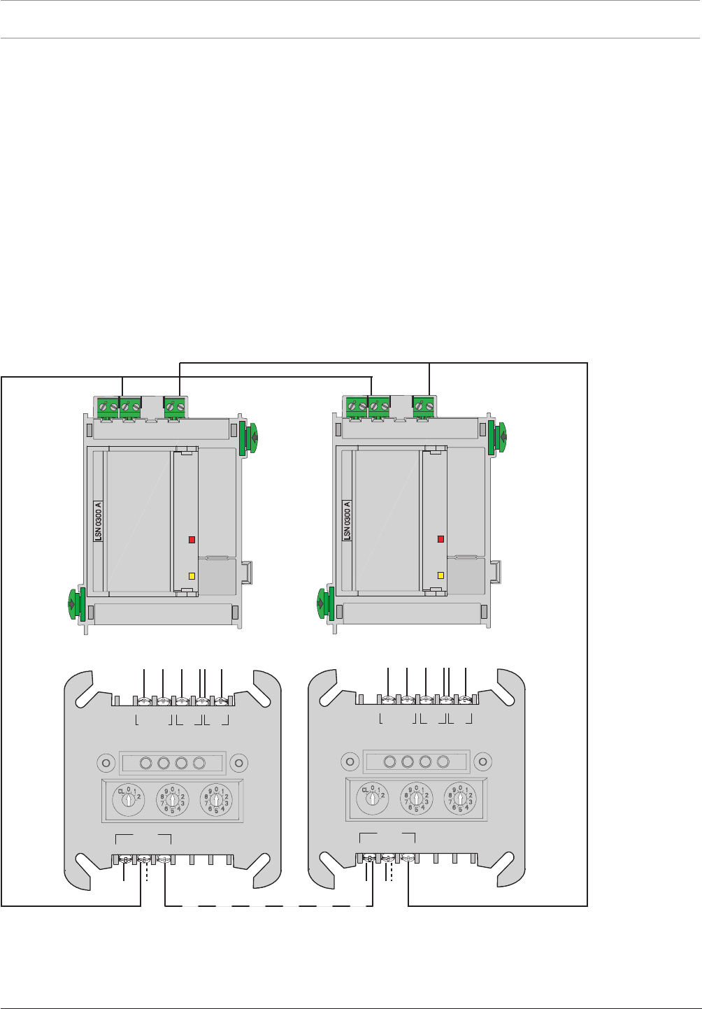
164 en | Appendix Modular Fire Panel
09.2017 | 11.3 | F.01U.028.089 System Information Bosch Sicherheitssysteme GmbH
8.3 Special Applications
8.3.1 Controlling Extinguishing Systems
The FPA enables the activation of extinguishing systems via the extinguishing interface
described in VDE0833 Part2 or by the VdS (standard interface SST in line with VdS Guideline
2496). Connection occurs either at the panel using the RMH0002A Relay Module for mains
power or in the field via the FLM‑420‑RLE Interface Module.
For each panel, a maximum of 8 extinguishing panels can be activated in each case via an
RMH0002A Relay Module for mains power. For each LSN loop, a maximum of 8 extinguishing
systems can be activated in each case via an FLM‑420‑RLE Interface Module.
The requirement is for a maximum of one extinguishing area to fail in the case of a system
fault. This means that from the second extinguishing area, there must be a redundant MPC
panel controller.
If several FLM-420-RLE Interface Modules are used to control the extinguishing system in each
LSN loop, in addition to the redundant panel controller, the associated LSN0300A or
LSN1500A module must also be duplicated.
LSN 0300 A
AUX1 LSN1 AUX2 LSN2
+ – a– b+ + – a– b+
b1+ a- b2+
LSN
REL1 FB2 FB1
NO COM –+
+
FLM-420-RLE-S
LSN 0300 A
AUX1 LSN1 AUX2 LSN2
+ – a– b+ + – a– b+
b1+ a- b2+
LSN
REL1 FB2 FB1
NO COM –+
+
FLM-420-RLE-S
Figure8.1: Several FLM-420-RLE modules in the LSN loop

Modular Fire Panel Index | en 165
Bosch Sicherheitssysteme GmbH System Information 09.2017 | 11.3 | F.01U.028.089
Index
A
Address 28, 92
Address card 25, 27, 92
License key 93, 94
Addressing 27, 95
Automatic 28
Manual 28
Rotary switch 95
AT 2000 Transmission System 121
AT3000 transmission unit 61
B
Batteries 6, 103
Battery Controller Module BCM
Configuration example 37
BCM Battery Controller Module 36, 101
Plug load 39
Standby current 40
Bracket, power supply 65
Building Management System 7, 23, 43
C
Cable
Bushings 51
Cable length 29, 32
Cable sets 120
CAN interface 7
Commissioning 141
Quick guide 141
Communication 111
20mA module 111
RS232 module 112
Components 158
Configuration
Example 7, 35
Contact rating 39
Conventional module 19, 107
D
Detection point 27, 92
Detector 19
Automatic 20
Manual 21
DIP switches 95
Display 12, 84
Disposal 143
Distributor rail 14, 15, 63
Documentation 43, 141, 143
Door control 23
Dummy cover plate 120
E
Earth bar 65
EN 54-2, Requirements 157
Extinguishing systems, Activation 164
Extranet 24, 43, 143
F
Fire detector cable 25
Fire service
Connection 107
Devices 22
Front doors 16, 17
FSM Fire Monitoring System 93
FSP-5000-RPS Programming Software 6, 141
System requirements 150
Functional module 9, 99, 111
Accessories 119
Annunciator module 101
BCM Battery Controller Module 101
Conventional module 107
Interfaces 110
LSN 1500mA 114
LSN 300mA 113
Notification appliance zone module 116
Relay module 117, 118
Technical data 150
Functional module: Communication 112
Functional module: Fire service interface 107
Functional module: Interfaces 109
Functional test 141
H
Height unit 59, 158
Housing
frame installation 13
Installation 44
Installation dimensions 146
Installation instructions 45
Installation types 17
Scope of delivery 16
Versions 6
Wall mounting 16
Weight 146
I
Installation 42
Documentation 43, 143
Instructions 42
MPC 88
Quick guide 43

166 en | Index Modular Fire Panel
09.2017 | 11.3 | F.01U.028.089 System Information Bosch Sicherheitssysteme GmbH
Installation kit, 482.6mm 15, 59, 158, 159
Height unit 59, 158
Interface modules 22
Interfaces 12
Module 109
Introduction 6
J
Junction board 61
K
Key deposit 23
L
Labeling strips 119
License key OPC 93, 94
License key PAVIRO 94
License key Praesideo 94
Limits 29, 32, 143, 144
Local Security Network, LSN 25, 28, 31
Cable length 28, 31
LSN module 25, 113, 114
M
Maintenance and service 143
Maximum limits 143, 144
Modular principle 9
Mounting frames 14
Mounting plate 63
Distributor rail 15, 63
N
Networking 12
Networking guide 24
Networking: Panel controller 86
Notification appliance
Audible 21
visual 21
Notification appliances 21
O
OPC license key 93, 94
OPC server 93, 94
P
Panel controller 11, 84, 148
Elements 85
Installation 84
Networking 86
Technical data 148
Panel rail 15
long 80
short 78
PAVIRO 7, 24, 94, 144
PAVIRO license key 94
Peripherals 18
Elements 19
Planning 9, 24
Instructions 24
Software 9, 10, 11, 24
Planning Software by Bosch 9, 10, 11, 24
Plena Voice Alarm System 7, 24
Power loss 146
Power supply
External 122
Power supply bracket 65
frame installation housing 65
Power supply unit 72
Praesideo 7, 24, 94, 144
Praesideo license key 94
Product IDs 158
R
Redundancy 25, 40
Addressing 96
Panel controller 40
Remote keypad 12
Addressing 140
Functional elements 128
Technical data 149
Wiring 137
Rotary switch 95
Rotary switch number (RSN) 95
S
Safety Instructions 6
Stickers 77
System limits 29, 32, 143, 144
T
Technical data
Functional modules 150
Panel controller 149
Power loss 146
Remote keypad 149
System limits 143, 144
Temperature sensor 65, 73
Test
Addressing/activation 142
Conventional/LSN functions 142
Power supply 142
Thermal printer 9, 123
Changing the paper roll 125
Jumpers 124
Transmission device 23
Transmission unit 61
Trouble Interface 122


168 en | Index Modular Fire Panel
09.2017 | 11.3 | F.01U.028.089 System Information Bosch Sicherheitssysteme GmbH

Bosch Sicherheitssysteme GmbH
Robert-Bosch-Ring 5
85630 Grasbrunn
Germany
www.boschsecurity.com
© Bosch Sicherheitssysteme GmbH, 2017
