Bosch Plena VAS Operation Manual En Us 18014411126996235
User Manual: Bosch en-us LBB1990/00 Controller
Open the PDF directly: View PDF ![]() .
.
Page Count: 192 [warning: Documents this large are best viewed by clicking the View PDF Link!]
- Title page
- Table of Contents
- Safety
- About this manual
- System overview
- Installation
- Connection
- Configuration
- Operation
- Troubleshooting
- Introduction
- Message or chime does not sound
- No pilot tone detected on EOL board
- No pilot tone detected on power amplifier
- No BGM on the router
- No BGM on controller or router
- No sound coming from the router
- Volume override only working for EMG, not for business calls (or similar problems)
- False Ground Short fault
- Start/Stop function on Trigger Inputs
- Processor Reset
- USB port not connected
- Data fault during configuration upload
- A click sounds through the loudspeakers at regular intervals
- Password not working
- Configuration download fails
- Can’t retrieve the original wave files with the configuration download
- Maintenance
- Technical data
- Appendices
- Back page
Plena
Voice Alarm System
en Installation and Operation manual

Table of contents
1Safety 8
1.1 Important Safeguards 8
1.2 Important Notices 8
2About this manual 9
2.1 Purpose of this manual 9
2.2 Intended audience 9
2.3 Related documentation 9
2.4 Alerts and notice signs 9
2.5 Conversion tables 10
2.6 Nomenclature 11
2.7 Document history 11
3System overview 12
3.1 Voice Alarm System 12
3.1.1 Application types 12
3.1.2 Application areas 12
3.1.3 Plena 12
3.1.4 Praesideo 12
3.2 Voice Alarm Controller 13
3.2.1 Hand-held microphone 13
3.2.2 Internal power amplifier 13
3.2.3 Internal message manager 13
3.2.4 Supervision 13
3.2.5 Trigger inputs 13
3.2.6 Remote control 14
3.2.7 Controls, connectors and indicators 14
3.3 Voice Alarm Router 18
3.3.1 Loudspeaker zones 18
3.3.2 Trigger inputs 18
3.3.3 External power amplifiers 18
3.3.4 Remote control 18
3.3.5 Controls, connectors and indicators 19
3.4 Call Station 21
3.4.1 Buttons 21
3.4.2 Supervision 21
3.4.3 Keypad 22
3.4.4 Controls, connectors and indicators 23
3.5 Call Station Keypad 24
3.6 Voice Alarm Remote Control 25
3.7 Voice Alarm Remote Control kit 27
3.8 Remote Control Extension 28
3.9 Remote Control Extension kit 29
3.10 Fireman’s Panel 30
3.11 End Of Line detection board 32
3.12 Application examples 32
3.12.1 Schools 32
3.12.2 Swimming pool 35
3.12.3 Shopping mall 37
Plena Table of Contents | en 3
Bosch Security Systems B.V. Installation and Operation manual 2013.07 | V2.0 |

3.12.4 Hotel 40
3.13 Calls and priorities 42
3.13.1 Priority 42
3.13.2 Mergeable messages 42
3.13.3 Business call 42
3.13.4 Emergency call 42
4Installation 43
4.1 Voice Alarm Controller 43
4.2 Voice Alarm Router 43
4.3 Call Station Keypad 44
4.4 Voice Alarm Remote Control 44
4.5 Voice Alarm Remote Control Kit 44
4.6 Remote Control Extension 45
4.7 Remote Control Extension Kit 45
4.8 End Of Line detection board 45
4.8.1 Installation of a single EOL 46
4.8.2 Installation of a multiple EOL in a daisy-chain 46
4.9 Dummy load 48
4.9.1 Set the jumper JP1 on the Dummy load 48
5Connection 49
5.1 Voice Alarm Controller 49
5.1.1 Emergency microphone 49
5.1.2 Call station 50
5.1.3 Voice alarm routers 51
5.1.4 External power amplifier 52
5.1.5 Remote controls 53
5.1.6 Loudspeakers 54
5.1.7 Volume overrides 56
5.1.8 Line output 58
5.1.9 Mic/line input with VOX 59
5.1.10 BGM inputs 60
5.1.11 Status output contacts 61
5.1.12 Power 62
5.1.13 Trigger inputs 64
5.2 Voice Alarm Router 66
5.2.1 Voice alarm controller 66
5.2.2 Loudspeakers 66
5.2.3 Volume overrides 66
5.2.4 Trigger inputs 66
5.2.5 External power amplifiers 67
5.2.6 Power 68
5.3 Call Station 69
5.3.1 Voice alarm controller 69
5.3.2 Power supply 69
5.3.3 Keypads 69
5.4 Voice Alarm Remote Control 70
5.4.1 Voice alarm controller 70
5.4.2 Remote control extensions 70
5.4.3 Status output contacts 70
4en | Table of Contents Plena
2013.07 | V2.0 | Installation and Operation manual Bosch Security Systems B.V.

5.4.4 Power 71
5.5 Voice Alarm Remote Control Kit 71
5.5.1 Rear panel 71
5.5.2 LEDs 71
5.5.3 Lamps 72
5.5.4 Relays 72
5.6 Remote Control Extension 73
5.6.1 Remote control 73
5.6.2 Status output contacts 73
5.6.3 Power 73
5.7 Remote Control Extension Kit 73
5.7.1 Rear panel 73
5.7.2 LEDs 73
5.7.3 Lamps 73
5.7.4 Relays 74
5.8 Fireman’s Panel 74
5.8.1 Voice alarm controller 74
5.8.2 Remote control extensions 74
5.8.3 Status output contacts 74
5.8.4 Power 74
6Configuration 75
6.1 System settings 75
6.1.1 Monitor 76
6.1.2 APR mode 76
6.1.3 Supervision 76
6.1.4 1-Channel mode operation 77
6.1.5 2-Channel mode operation 78
6.2 Supervision 78
6.2.1 Processor reset 79
6.2.2 Network 79
6.2.3 Power amplifiers 79
6.2.4 Ground short 79
6.2.5 Emergency trigger inputs 80
6.2.6 Mains power 80
6.2.7 Battery 80
6.2.8 Message supervision 80
6.2.9 Emergency microphone 80
6.2.10 Line supervision 80
6.3 Voice alarm controller 81
6.3.1 VOX configuration 81
6.3.2 VOX 82
6.3.3 Speech filter 82
6.3.4 Phantom power 82
6.3.5 Voice alarm router 82
6.3.6 Router ID 82
6.3.7 Termination switch 82
6.4 Call station 83
6.4.1 Call station ID 83
6.4.2 Sensitivity 83
Plena Table of Contents | en 5
Bosch Security Systems B.V. Installation and Operation manual 2013.07 | V2.0 |

6.4.3 Speech filter 84
6.4.4 Termination 84
6.5 Remote control 85
6.5.1 Remote control ID 85
6.5.2 Monitor 85
6.5.3 Termination switch 85
6.6 Remote control extension 86
6.6.1 Remote control extension ID 86
6.6.2 Termination switch 86
7Operation 87
7.1 Switch on 87
7.1.1 Voice alarm controller 87
7.1.2 Voice alarm router 87
7.1.3 Calibration 87
7.2 Background music 88
7.2.1 Select BGM source 88
7.2.2 Select zones 88
7.2.3 Adjust volume 89
7.2.4 Adjust frequencies 89
7.3 Business calls 89
7.3.1 Select zones 90
7.3.2 Make the announcement 90
7.4 Emergency state 91
7.4.1 Enter the emergency state 91
7.4.2 Acknowledge the emergency state 92
7.4.3 Exit the emergency state 92
7.4.4 Distribute live speech 92
7.4.5 Select zones 93
7.4.6 Make the announcement 94
7.4.7 Distribute the alert message 94
7.4.8 Distribute the alarm message 96
7.5 Fault State 96
7.5.1 Acknowledge the fault state 96
7.5.2 Reset the fault state 97
7.5.3 Fault indicators 98
8Troubleshooting 101
8.1 Introduction 101
8.2 Message or chime does not sound 101
8.3 No pilot tone detected on EOL board 101
8.4 No pilot tone detected on power amplifier 101
8.5 No BGM on the router 101
8.6 No BGM on controller or router 101
8.7 No sound coming from the router 102
8.8 Volume override only working for EMG, not for business calls (or similar problems) 102
8.9 False Ground Short fault 102
8.10 Start/Stop function on Trigger Inputs 102
8.11 Processor Reset 103
8.12 USB port not connected 103
8.13 Data fault during configuration upload 103
6en | Table of Contents Plena
2013.07 | V2.0 | Installation and Operation manual Bosch Security Systems B.V.

8.14 A click sounds through the loudspeakers at regular intervals 103
8.15 Password not working 103
8.16 Configuration download fails 103
8.17 Can’t retrieve the original wave files with the configuration download 104
9Maintenance 105
9.1 Clean the units 105
9.2 Clean air inlets 105
9.3 Check the connectors and grounding 105
10 Technical data 106
10.1 Electrical 106
10.1.1 Voice Alarm Controller 106
10.1.2 Voice Alarm Router 109
10.1.3 Call Station 110
10.2 Physical characteristics 110
10.2.1 Voice Alarm Controller 110
10.2.2 Voice Alarm Router 111
10.2.3 Call Station 111
10.2.4 Call Station Keypad 111
10.2.5 Voice Alarm Remote Control 111
10.2.6 Voice Alarm Remote Control Kit 111
10.2.7 Remote Control Extension 111
10.2.8 Remote Control Extension Kit 111
10.2.9 Fireman’s Panel 112
10.2.10 End of line detection board 112
10.3 Environmental conditions 112
10.3.1 Voice Alarm Controller 112
10.3.2 Voice Alarm Router 112
10.3.3 Call Station 112
10.4 Standards 113
10.4.1 Voice Alarm Controller 113
11 Appendices 114
11.1 Compliancy checklists 114
11.1.1 Emergency Sound Systems 114
11.1.2 EN60849: 1998 116
11.1.3 EN60849 - When using the Remote Control Kits: 135
11.1.4 EN54-16 136
Plena Table of Contents | en 7
Bosch Security Systems B.V. Installation and Operation manual 2013.07 | V2.0 |

Safety
Important Safeguards
Prior to installing or operating products, always read the Important Safety Instructions which
are available as a separate multilingual document: Important Safety Instructions (Safety_ML).
These instructions are supplied together with all equipment that can be connected to the
mains supply.
Important Notices
When using routers, keypads or more than one call station, configure the controller using the
supplied software.
Use shielded cable (CAT-5) between the routers and the controller.
The factory default setting of the Plena Voice Alarm System Controller is as follows:
– One channel system.
– Supervision off.
– Please read the latest release notes for the version of the hardware and software you are
using. With firmware (e.g. 3.01.01), the first digit is a major release, where backward
compatibility is not guaranteed, second digits are changes in functionality that are
backward compatible, the last digits are for bug fixes without impact on functionality.
Lastly, the PC configuration software may have an Rx suffix, that indicates changes to the
PC configuration software without changes to firmware.
1
1.1
1.2
8en | Safety Plena
2013.07 | V2.0 | Installation and Operation manual Bosch Security Systems B.V.
About this manual
Purpose of this manual
The purpose of the Installation and Operation manual is to provide information that is required
to install, configure and operate a Plena Voice Alarm System.
Intended audience
The Installation and Operation manual is intended for installers and users of an (extensive)
Plena Voice Alarm System.
Related documentation
The following related document is available:
– Plena Voice Alarm System Configuration Software Manual.
– Refer to the product related information on www.boschsecurity.com.
Alerts and notice signs
Four types of signs can be used in this manual. The type is closely related to the effect that
may be caused if it is not observed. These signs - from least severe effect to most severe
effect - are:
Notice!
Containing additional information. Usually, not observing a ‘notice’ does not result in damage
to the equipment or personal injuries.
!
Caution!
The equipment or the property can be damaged, or persons can be lightly injured if the alert
is not observed.
!
Warning!
The equipment or the property can be seriously damaged, or persons can be severely injured
if the alert is not observed.
Danger!
Not observing the alert can lead to severe injuries or death.
2
2.1
2.2
2.3
2.4
Plena About this manual | en 9
Bosch Security Systems B.V. Installation and Operation manual 2013.07 | V2.0 |
Conversion tables
In this manual, SI units are used to express lengths, masses, temperatures etc. These can be
converted to non-metric units using the information provided below.
1 in = 25.4 mm 1 mm = 0.03937 in
1 in = 2.54 cm 1 cm = 0.3937 in
1 ft = 0.3048 m 1 m = 3.281 ft
1 mi = 1.609 km 1 km = 0.622 mi
Table 2.1: Conversion of units of length
1 lb = 0.4536 kg 1 kg = 2.2046 lb
Table 2.2: Conversion of units of mass
1 psi = 68.95 hPa 1 hPa = 0.0145 psi
Table 2.3: Conversion of units of pressure
Notice!
1 hPa = 1 mbar
°F = _ . °C + 32
9
5
°C = _ . (°F - 32)
5
9
2.5
10 en | About this manual Plena
2013.07 | V2.0 | Installation and Operation manual Bosch Security Systems B.V.

Nomenclature
Throughout this manual, terms like “Controller”, “Router” and “Remote Control” are used to
describe the various component types, as indicated below.
Component description Component type designation
Power Amplifier 360/240W LBB 1935/20
Power Amplifier 720/480W LBB 1938/20
Call Station LBB 1956/00
Call Station Keypad LBB 1957/00
Controller LBB 1990/00
Router LBB 1992/00
Fireman's panel LBB 1995/00
Remote Control LBB 1996/00
Remote Control Extension LBB 1997/00
Loop Amplifier PLN-1LA10
Dummy load PLN‑DMY60
End-of-Line board PLN‑1EOL
Table 2.4: Component description and type designation
Component description Component type designation
Remote Control kit LBB1998/00
Remote Control Extension kit LBB1999/00
Power Amplifier 720/480W PLN‑1P1000
Surge and transiens suppression board PM1‑6SP
Table 2.5: Component description and type designation
Document history
Release date Documentation version Reason
2013.07.07 V2.0 – 2nd edition
2.6
2.7
Plena About this manual | en 11
Bosch Security Systems B.V. Installation and Operation manual 2013.07 | V2.0 |

System overview
Voice Alarm System
The Plena Voice Alarm System is a public address and voice alarm system in which features for
compliance to evacuation standards such as EN60849, NEN2575, BS5839/8 and EN54-16 are
integrated.
Application types
Typically, the Plena Voice Alarm System is used to create small systems that must comply to
evacuation standards, medium-sized systems in which one call channel is enough and large
systems that consist of many small zones.
Application areas
The application areas of the Plena Voice Alarm System include:
– Supermarkets, shops
– Factories
– High-rise buildings
– Office buildings
– Schools
– Recreational facilities
– Hotels
– Small airports
Plena
The Plena Voice Alarm System is part of the Plena product range. Plena provides public
address solutions for places where people gather to work, worship, trade or simply enjoy
themselves. It is a family of system elements that are combined to create public address
systems tailored for virtually any application. The range includes mixer, pre, system and power
amplifiers, a source unit, digital message manager, feedback suppressor, conventional and PC
call stations, an ‘All-in-One’ system, an audio interface, a timer, a charger, a loop amplifier, a
BGM source and a voice alarm system. Each element is designed to complement all others
thanks to matched acoustical, electrical and mechanical specifications.
Praesideo
It is possible to combine the Plena Voice Alarm System with e.g. a Praesideo digital public
address and emergency sound system, or a Promatrix or other system. When an audio output
of Praesideo is connected to a VOX audio input of the Plena Voice Alarm System, calls that are
made by the Praesideo system overrule the calls that are made with the Plena Voice Alarm
System.
3
3.1
3.1.1
3.1.2
3.1.3
3.1.4
12 en | System overview Plena
2013.07 | V2.0 | Installation and Operation manual Bosch Security Systems B.V.
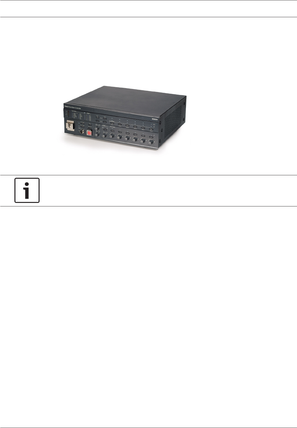
Voice Alarm Controller
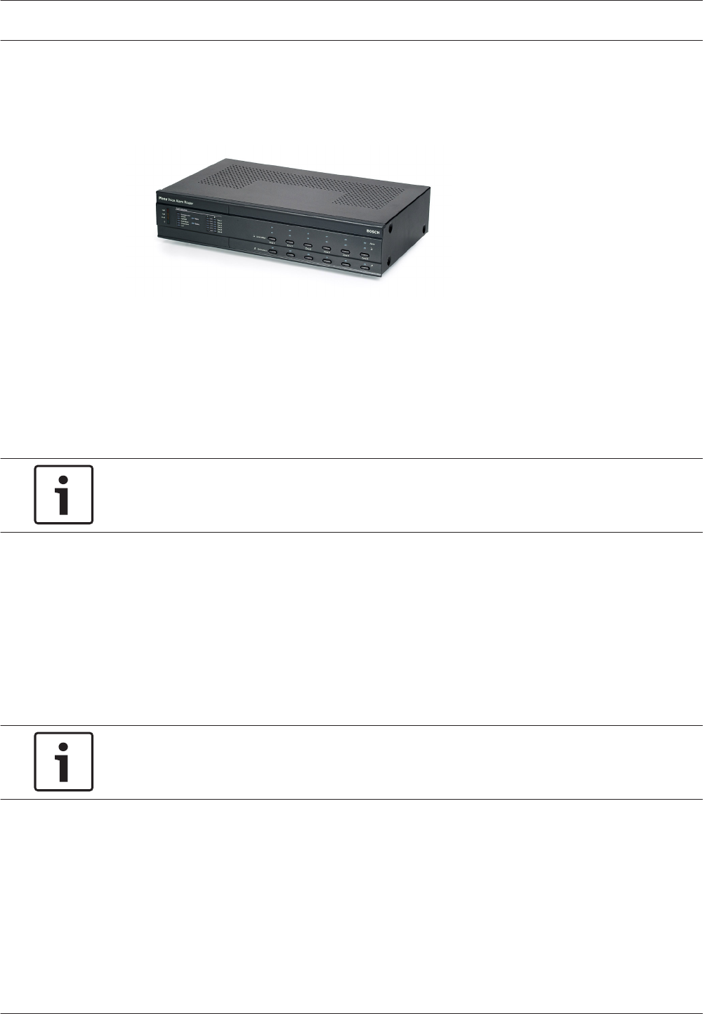
The Voice Alarm Controller is the heart of the Plena Voice Alarm System. The voice alarm
controller distributes emergency calls, business calls as well as background music (BGM) to
up to 6 loudspeaker zones.
Figure 3.1: Voice Alarm Controller
Notice!
When the voice alarm controller has been purchased in the Asian-Pacific Region, the
emergency button has a different cover.
Hand-held microphone
The voice alarm controller is equipped with a hand-held microphone, which can be used to
make emergency calls.
Internal power amplifier
The voice alarm controller has a 240 W internal power amplifier, which can be used in
1‑channel or 2‑channel mode. In the 1‑channel mode, all calls and BGM are amplified by the
internal power amplifier. If desired, an external power amplifier can be connected for spare
switching. In the 2‑channel mode, the BGM is amplified by the internal power amplifier,
whereas the calls are amplified by an external power amplifier.
Internal message manager
The voice alarm controller has an internal message manager, which maps wave files (.wav) to
messages that can be played by the Plena Voice Alarm System.
Supervision
All necessary supervision features for compliance to evacuation standards are integrated into
the voice alarm controller. If supervision is enabled and a fault is detected, the voice alarm
controller lights a LED on its front panel that indicates the cause of the fault.
Trigger inputs
The voice alarm controller has a terminal block to which 6 emergency (EMG) and 6 business
trigger inputs can be connected. Third party systems can use the trigger inputs to start
emergency and business calls in the Plena Voice Alarm System.
3.2
3.2.1
3.2.2
3.2.3
3.2.4
3.2.5
Plena System overview | en 13
Bosch Security Systems B.V. Installation and Operation manual 2013.07 | V2.0 |
Remote control
With the Voice Alarm Remote Control, it is possible to control the voice alarm controller from
another site. The remote control is also available as kit (Voice Alarm Remote Control Kit) for
creating customized solutions. The maximum number of remote controls that can be
connected to the voice alarm controller is 2. A special type of remote control is the Fireman’s
Panel.
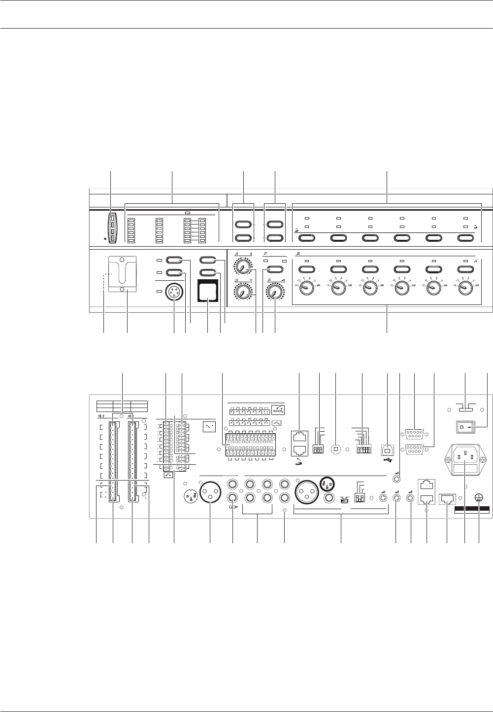
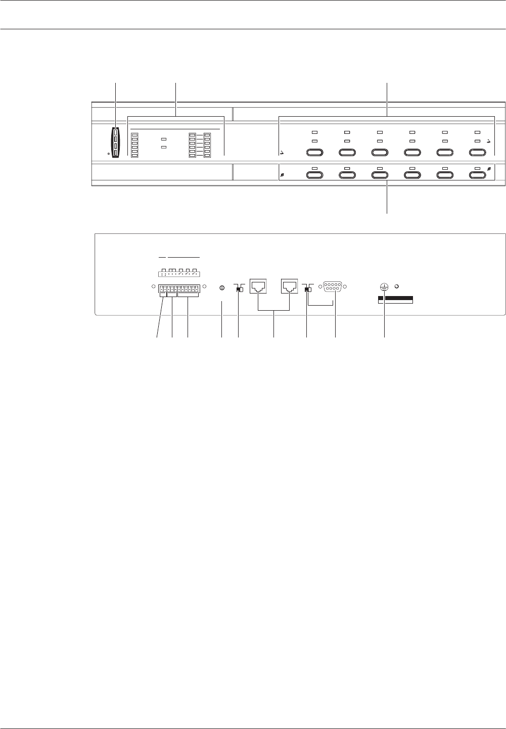
Controls, connectors and indicators
0
-+
-+
0 dB
-6dB
-20dB
Processor reset
Network
Call/EMG
Music/Spare
Ground short
Input
Mains
Battery
Zone1
Zone2
Zone3
Zone4
Zone5
Zone6
Alarm
Zone select
Plena Voice Alarm Controller
Fault Indicators
CD/Tuner Aux
Select Zone select
Indicator test
EMG mic
Alert message
Alarm message
All call
Zone1 Zone2 Zone3 Zone4 Zone5 Zone6
Fault EMG
Ack
Reset
AB
Disabled
Message
EMG mic
RCP
Router
CO M
NC N O
10k 10k
Trigger input/24V DC out
Business
Emergency
NC
TRG2
Override/Trigger Output
AUX
L
R
PC
Digital
Mess age
Monitoring
Speaker
Remote Control Panel
Impedance
Calibration
In
LBB 1 990 /00 8900 199 0 0 001
Plena Voice Alarm Controller
Max. output power 360W
Rated output power 240W
115-230V~, 50/60Hz
S/N.
Design & Quality
The Netherlands
N663
Phantom power
Z1
Z2
Z3
Z4
Z5
Z6
Ext
B ooster
In
DC In
100V
0
TRG 1
Int
B ooster
Out
24V
EM G
Fault
C all
External Booster
Out
CD/Tuner
SEL1
SEL0
Firmware
Upgrade
Monitor
APR mode
Supervision
2ch operation
Reserved
Off
On
USB
Vox
Speech filter
Mic/Line
Vox
Reserved
Rated input power:760VA
Line fuse
T6.3L250V for230V AC
T10L250V for115V AC
115V~ 230V~
Apparatus delivered
C onnected for 230V~
Power
Router
W arning
This apparatus must be earthed
100V
0
100V
0
100V
0
100V
0
100V
0
100V
0
24V
70 V
Z1
Z2
Z3
Z4
Z5
Z6
GND
Reserved
1 2 3 4 5 6
1 2 3 4 5 6
1 2 3 4 5 6
Off
On
Off
On
Call station For ser vice only
GND
24V
DC out
VOX
Switch
VOX Switch
1 2 3 4 5 6
NC
COM
NO
NC
COM
NO
NC
COM
NO
100V
0
C all out
100V
0
100V
0
100V
0
100V
0
100V
0
100V
0
Z2
Z3
Z4
Z5
Z6
Z1
A B
NO
24V
DC out
24V
1 Channel 2 Channel
Int Booster
Ext Booster
BGM / Spare
N.C ./ Spare
Call
BGM / C all
Volume Override
100 V
Made in China
1
2
1
2
EMG. Mic
12 3 4 5
6712151617
32333435363739
1013
89
384041424647
18 19 20 22 23 24 25 26 27 28 30 312921
4445 43
1114
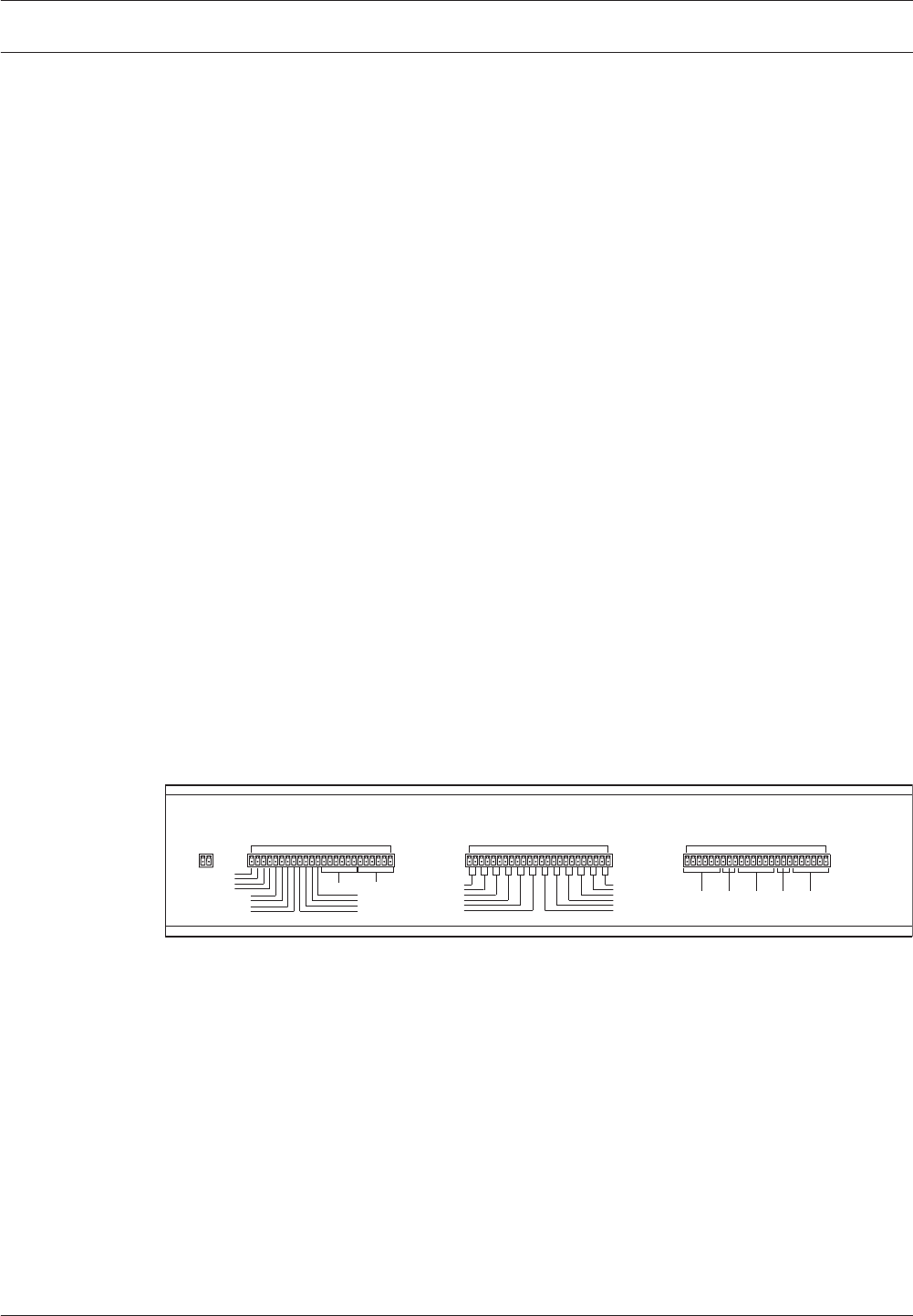
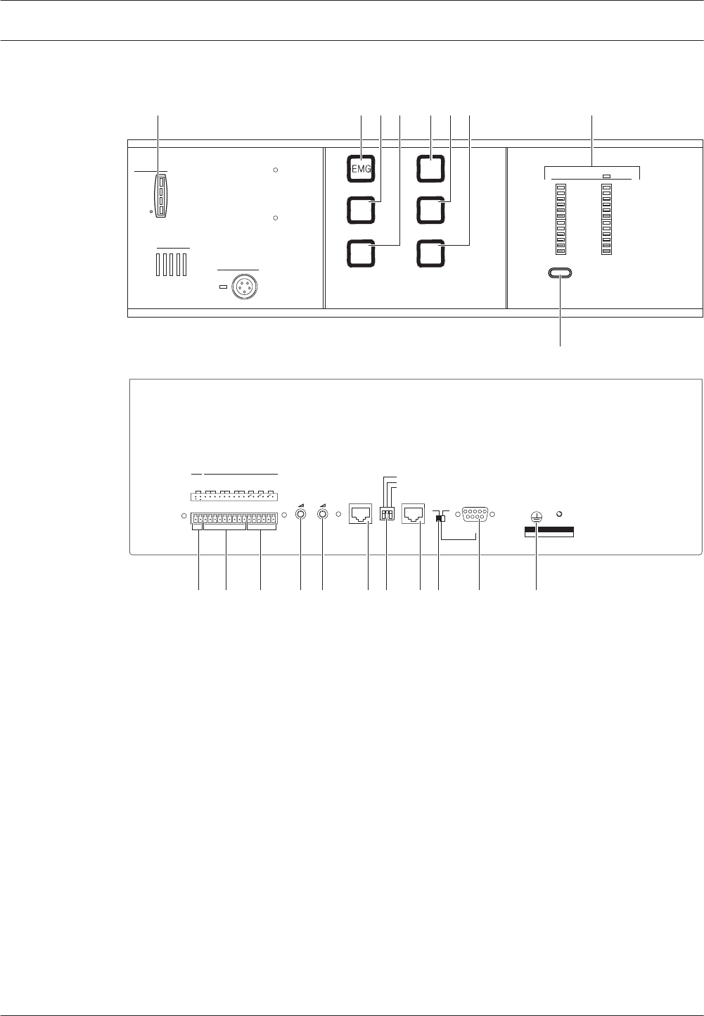
Figure 3.2: Front and rear views of the voice alarm controller
Controls, connectors and indicators on the voice alarm controller:
1. Power LED/VU Meter:
A combined power indicator and VU meter. The green power LED is lit if the voice alarm
controller is connected to the mains or back-up power and switched on. The VU meter
indicates the master VU level: 0 dB (red), 6 dB, -20 dB (yellow).
Notice: As the pilot-tone level of the VAS is -20 dB or -23 dB in some amplifiers, the -20
dB LED will be on continuously. This is normal.
3.2.6
3.2.7
14 en | System overview Plena
2013.07 | V2.0 | Installation and Operation manual Bosch Security Systems B.V.

2. Fault indicators:
Twelve yellow system fault LEDs (Processor reset, Network, Call/EMG, Music/Spare,
Ground short, Input, Mains, Battery, Message, EMG mic, RCP and Router) and twelve
yellow loudspeaker line fault LEDs. Fault indication is only possible if supervision is
enabled (see section Fault indicators, page 98). If supervision is disabled, the yellow
Disabled LED is lit.
3. Fault state buttons:
Two buttons to acknowledge (Ack) and reset (Reset) the fault state (see section Fault
State, page 96).
4. Emergency state buttons:
Two buttons to acknowledge (Ack) and reset (Reset) the emergency state (see section
Emergency state, page 91).
5. Emergency call zone selectors:
Six buttons to select the zones to which the emergency call must be distributed (see
section Emergency state, page 91). Each button has a green and a red LED. The six red
LEDs indicate the zones that are selected for the emergency call. The six green LEDs
indicate the zones in which a business call is running.
6. BGM zone selectors:
Six buttons to select the zones to which the BGM is distributed (see section Background
music, page 88). Each button has a green LED and a rotary knob. The six green LEDs
indicate the zones to which BGM is distributed. The six rotary knobs are local volume
controls that can be used to adjust the volume of the BGM in each zone. Each volume
control knob has six settings.
7. BGM master volume control:
A rotary knob to set the master volume of the BGM (see section Background music, page
88).
8. BGM source selector:
A button to select the BGM source (CD/Tuner or Aux). The selected source is indicated
with a green LED (see section Background music, page 88).
9. BGM tone controls:
Two rotary knobs to control the high and low frequencies of the BGM (see section
Background music, page 88).
10. All call button:
A button to select all zones. This button is only available in the emergency state (see
section Emergency state, page 91).
11. Indicator test button:
A button to test all LEDs on the front panel of the voice alarm controller, and connected
voice alarm routers, remote control panels, remote control extensions and fireman’s
panels. All LEDs are lit as long as the button is pushed (see section Fault State, page
96).
12. Emergency button:
A push button to put the system in the emergency state (see sectionEmergency state, page
91).
13. Alert message button:
A button to select the alert message. This button is only available in the emergency state
(see section Emergency state, page 91).
14. Alarm message button:
A button to select the default alarm message. This button is only available in the
emergency state (see section Emergency state, page 91).
Plena System overview | en 15
Bosch Security Systems B.V. Installation and Operation manual 2013.07 | V2.0 |

15. Microphone socket:
A socket to connect the hand-held emergency microphone (see section Emergency
microphone, page 49).
16. Bracket:
A bracket for the hand-held emergency microphone that is supplied with the voice alarm
controller.
17. Monitoring speaker:
Built-in monitoring speaker.
18. Zone outputs:
Six zone outputs to connect loudspeakers to the voice alarm controller. Each zone output
consists of two loudspeaker line outputs (see section Loudspeakers, page 54).
19. Override outputs:
Six volume override outputs to override local volume controls in each zone (see section
Volume overrides, page 56).
20. Status outputs:
Three status outputs to send the status of the Plena Voice Alarm System to third party
equipment (see section Status output contacts, page 61).
21. Trigger inputs/24 V DC output:
Twelve trigger inputs to receive signals from third party equipment and one 24 V(DC)
output (see section Trigger inputs, page 64).
22. Call station sockets:
Two RJ45 sockets to connect call stations to the voice alarm controller (see section Call
station, page 50).
23. Service settings:
A set of DIP switches to service the voice alarm controller. Do not change the positions of
the switches.
24. Calibration switch:
A switch to calibrate the impedances of the loudspeaker lines for loudspeaker supervision
(see section Calibration, page 87).
25. Configuration settings:
A set of DIP switches to configure the system (see section System settings, page 75).
26. PC socket:
A USB socket to connect the voice alarm controller to a PC.
Refer to the Configuration Software Manual for more information about connecting a PC
to the voice alarm controller.
27. Emergency microphone volume control:
A rotary knob to set the volume of the hand-held emergency microphone.
28. Reserved.
29. Reserved:
To connect an OI, or for upgrades (only for authorized use).
30. Voltage selector:
A voltage selector to select the local mains voltage (see section Power, page 62).
31. Power switch:
A switch to switch the voice alarm controller on and off (see section Power, page 62).
32. Ground:
A connection to electrically ground the voice alarm controller.
33. Mains power inlet:
A socket to connect the voice alarm controller to the mains power (see section Power,
page 62).
16 en | System overview Plena
2013.07 | V2.0 | Installation and Operation manual Bosch Security Systems B.V.

34. Router socket:
An RJ45 socket to connect voice alarm routers to the voice alarm controller (see section
Voice alarm routers, page 51).
35. Remote control panel socket:
Two RJ45 sockets to connect remote control panels (Fireman’s panel, Remote Control,
Remote Control kit) to the voice alarm controller.
36. Monitoring speaker volume control:
A rotary knob to set the volume of the monitoring loudspeaker.
37. Digital message volume control:
A rotary knob to set the volume of the digital messages. This volume control does not
influence the volume of the emergency messages.
38. Mic/line input with VOX functionality:
An XLR socket and a 6.3 mm jack with voice-activated (VOX) functionality to connect a
microphone or line input to the voice alarm controller (see section Mic/line input with
VOX, page 59). The VOX settings are configured with the DIP switches and the source
switch (see section VOX configuration, page 81).
39. PC Call station input:
An input to connect a PC call station. For future use.
40. BGM inputs:
Two inputs to connect background music sources. Each input consists of two cinch
sockets (see section BGM inputs, page 60).
41. Line output:
A line output to connect an external recording device to record the audio of the Plena
Voice Alarm System (see section Line output, page 58).
42. External power amplifier (output):
An XLR socket to connect an external power amplifier (see section External power
amplifier, page 52). This socket is used in combination with the external power amplifier
input (no. 47).
43. Trigger outputs:
Two general purpose trigger outputs. For future use. TR1 is active during impedance
check.
44. Internal power amplifier output:
Three pins that provide the 100 V audio signal of the internal power amplifier of the voice
alarm controller. Also includes a 70 V connection.
45. Call output:
An output that provides the call audio of the Plena Voice Alarm System.
46. Back-up power inlet:
An inlet to connect a back-up power supply to the voice alarm controller (see section
Power, page 62).
47. External power amplifier (input):
An input to connect an external power amplifier (see section External power amplifier,
page 52). These pins are used in combination with the external power amplifier output
(no. 42).
Plena System overview | en 17
Bosch Security Systems B.V. Installation and Operation manual 2013.07 | V2.0 |
Voice Alarm Router
With the Voice Alarm Router, the number of loudspeaker zones and trigger inputs in the
system can be increased.
Figure 3.3: Voice alarm router
Loudspeaker zones
A voice alarm controller can serve and manage 6 loudspeaker zones. To increase the number
of zones in the system, one or more Voice Alarm Routers can be connected to the voice alarm
controller. Each router adds a maximum of 6 zones to the system. As the maximum number of
voice alarm routers that can be connected in a system is 19, the maximum number of zones in
a Plena Voice Alarm System is 120 (from hardware and software version 3.x onwards).
Notice!
If older routers are used (version 2.x or higher), 60 zones can be addressed. The
recommendation is to always use 3.x hardware in combination with each other.
Trigger inputs
A voice alarm controller can manage 6 emergency (EMG) and 6 business trigger inputs. To
increase the number of EMG and trigger inputs, one or more voice alarm routers can be
connected to the voice alarm controller. Each router adds a maximum of 6 EMG trigger inputs
and 6 business trigger inputs to the system. As the maximum number of voice alarm routers
that can be connected in a system is 19, the maximum number of EMG trigger inputs in a
Plena Voice Alarm Systemis 120 (from hardware and software version 3.x onwards).
The maximum number of business trigger inputs in a Plena Voice Alarm System is also 120
(from hardware and software version 3.x onwards).
Notice!
If older routers are used (version 2.x or higher), 60 zones can be addressed. The
recommendation is to always use 3.x hardware in combination with each other.
External power amplifiers
The voice alarm router does not have an internal power amplifier. When the power that is
supplied by the voice alarm controller is insufficient, to each voice alarm router two external
power amplifiers can be connected. In a multi‑router system, multiple power amplifiers can be
connected to amplify calls and background music (BGM) or just for backup purposes.
Remote control
With the Voice Alarm Remote Control Extension, it is possible to control the voice alarm router
from another location. The remote control extension is also available as a kit (Voice Alarm
Remote Extension Kit) for creating customized solutions.
3.3
3.3.1
3.3.2
3.3.3
3.3.4
18 en | System overview Plena
2013.07 | V2.0 | Installation and Operation manual Bosch Security Systems B.V.
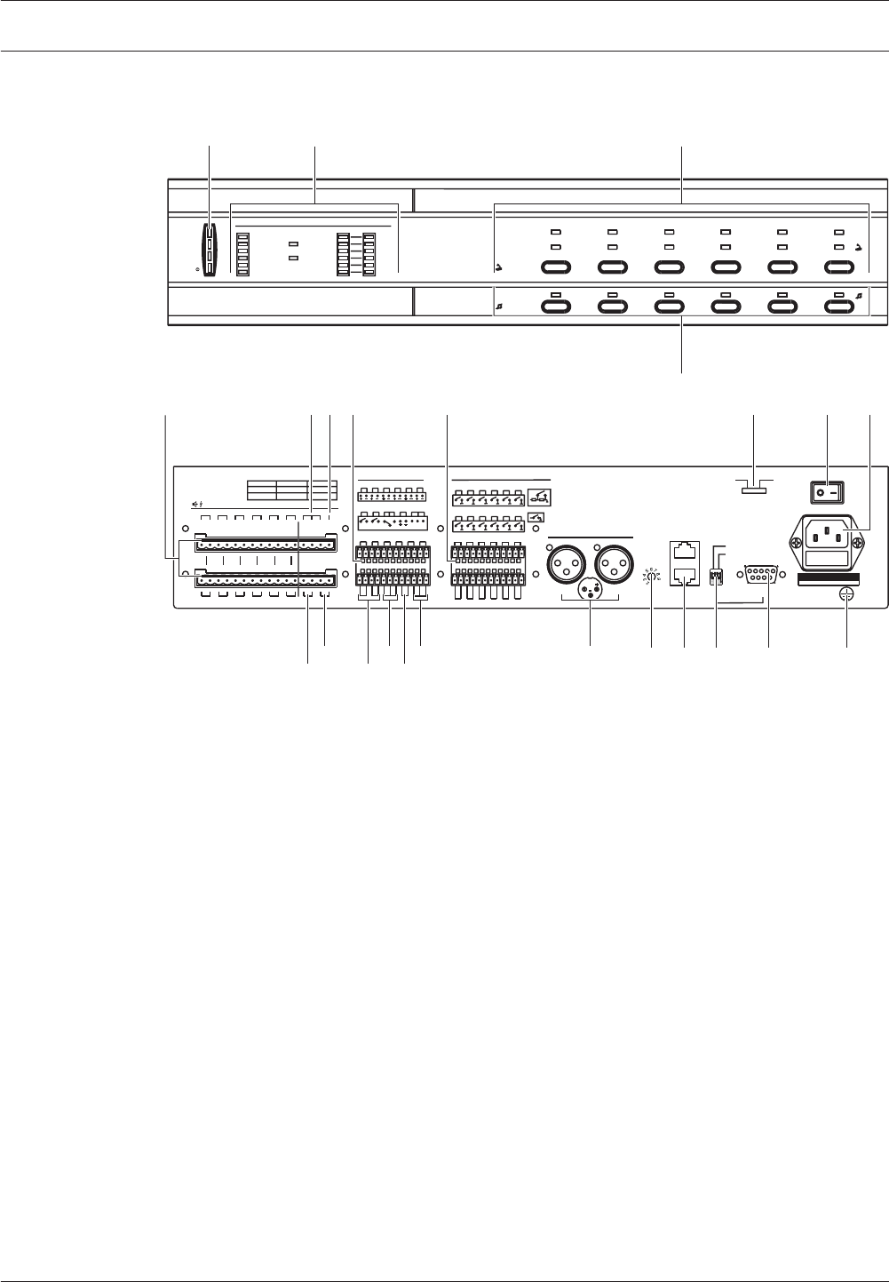
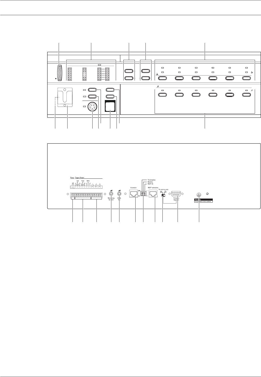
Controls, connectors and indicators
Plena Voice Alarm Router
0 dB
-6dB
-20dB
B
Processor reset
Network
Call/EMG
Music/Spare
Ground short
Input
Mains
Battery
Zone1
Zone2
Zone3
Zone4
Zone5
Zone6
Alarm
Zone select
A
Fault Indicators
Zone select
Zone1 Zone2 Zone3 Zone4 Zone5 Zone6
10k 10k
Booster 1 in
Override/Trigger Output Trigger Input
Business
Emergency
Firmware upgrade
Firmware Upgrade
LBB 1992/00 8900 199 20001
Plena Voice Alarm Router
115-230V~,50/60Hz
S/N.
Design & Quality
The Netherlands
N663
Termination
100V 0 100V 0 100V 0 100V 0 100V 0 100V 0 100V 70V 0 100V
Z1 Z2 Z3 Z4 Z5 Z6
Booster 1
Out
1...9
ID
Router
Rated input power:100VA
Line fuse:T1L250V for 230V AC
T2L250V for 115V AC
Warning
This apparatus must be earthde
TRG1 TRG2
1 2 3 4 5 6
COM
NC NO
1 2 3 4 5 6
1 2 3 4 5 6
1 2 3 4 5 6
Z1 Z2 Z3 Z4 Z5
Booster
Failure
GND
Booster 2
Z6
24V
DC Out
TRG1 TRG2
Booster
Failure
24V
DC Out
A
100V 0 100V 0 100V 0 100V 0 100V 0 100V 0 100V 0 +24V-
Booster 2 in
Z1 Z2 Z3 Z4 Z5 Z6
B
DC In
Z1 Z2 Z3 Z4 Z5 Z6
24V
1 Channel 2 Channel
Booster 1
Booster 2
BGM/ Spare
N.C./Spare Call
BGM/ Call
V.O.R.
V.O.R.
NC NO
24V
In
Out
Power
Appara tu s de li vered
Co nn ec ted for 230 V~
115V~ 230V~
Call out
Made in China
Off
On
1
76
2 3
4
5 9 10 118 12
1314151617
1819
2024
21
22
23
Figure 3.4: Front and rear views of the voice alarm router
Controls, indicators and connectors on the voice alarm router:
1. Power LED/VU Meter:
A combined power indicator and VU meter. The green power LED is lit if the voice alarm
router is connected to the mains or back-up power and switched on. The VU meter
indicates the master VU level: 0 dB (red), -6 dB, -20 dB (yellow).
2. Fault indicators:
Eight yellow system fault LEDs (Processor reset, Network, Call/EMG, Music/Spare,
Ground short, Input, Mains, Battery) and twelve yellow loudspeaker line fault LEDs. Fault
indication is only possible if supervision is enabled (see section Fault indicators, page
98).
3. Emergency call zone selectors:
Six buttons to select the zones to which the emergency call must be distributed (see
section Emergency state, page 91). Each button has a green and a red LED. The six red
LEDs indicate the zones that are selected for the emergency call. The six green LEDs
indicate the zones in which a business call is running.
4. BGM zone selectors:
Six buttons to select the zones to which the BGM is distributed (see section Background
music, page 88). Each button has a green LED. The six green LEDs indicate the zones to
which BGM is distributed.
5. Zone outputs:
Six zone outputs to connect loudspeakers to the voice alarm router. Each zone output
consists of two loudspeaker line outputs (see section Loudspeakers, page 66).
3.3.5
Plena System overview | en 19
Bosch Security Systems B.V. Installation and Operation manual 2013.07 | V2.0 |

6. External power amplifier 1 (input):
An input to connect an external power amplifier (see section External power amplifiers,
page 67). These pins are used in combination with the external power amplifier output
(no. 18).
7. Call output:
An output that provides the call audio of the Plena Voice Alarm System.
8. Override outputs:
Six volume override outputs to override local volume controls in each zone (see section
Volume overrides, page 66).
9. Trigger inputs:
Twelve trigger inputs to receive signals from third party equipment (see section Trigger
inputs, page 66).
10. Voltage selector:
A voltage selector to select the local mains voltage (see section Power, page 68).
11. Power switch:
A switch to switch the voice alarm router on and off (see section Power, page 68).
12. Mains power inlet:
A socket to connect the voice alarm router to the mains power (see section Power, page
68).
13. Ground:
A connection to electrically ground the router.
14. Firmware upgrade connector:
An RS232 connector to connect a PC to upgrade the firmware of the voice alarm router.
15. Configuration settings:
A set of DIP switches to configure the voice alarm router (see section Voice alarm router,
page 82).
16. System sockets:
Two RJ45 sockets to connect other voice alarm routers to the voice alarm router (see
section Voice alarm routers, page 51).
17. Router ID:
A rotary switch to set the ID of the router (see section Voice alarm router, page 82).
18. External power amplifier (output):
Two XLR sockets to connect external power amplifiers (see section External power
amplifier, page 52). This socket is used in combination with the external power amplifier
inputs (no. 6 and 24).
19. Volume override:
Three contacts (NC/24V/NO) to connect a fail-safe or a power-saving 4-wire volume
override (see section Volume overrides, page 56).
20. 24 VDC output: 800 mA.
21. Power amplifier failure:
Two pins (NC relays) to report a failure of the power amplifier.
22. Trigger outputs:
Two general purpose trigger outputs. For future use.
23. Back-up power inlet:
An inlet to connect a back-up power supply to the voice alarm router (see section Power,
page 68).
24. External power amplifier 2 (input):
An input to connect an external power amplifier (see section Voice Alarm Router, page
109). These pins are used in combination with the external power amplifier output (no.
18).
20 en | System overview Plena
2013.07 | V2.0 | Installation and Operation manual Bosch Security Systems B.V.
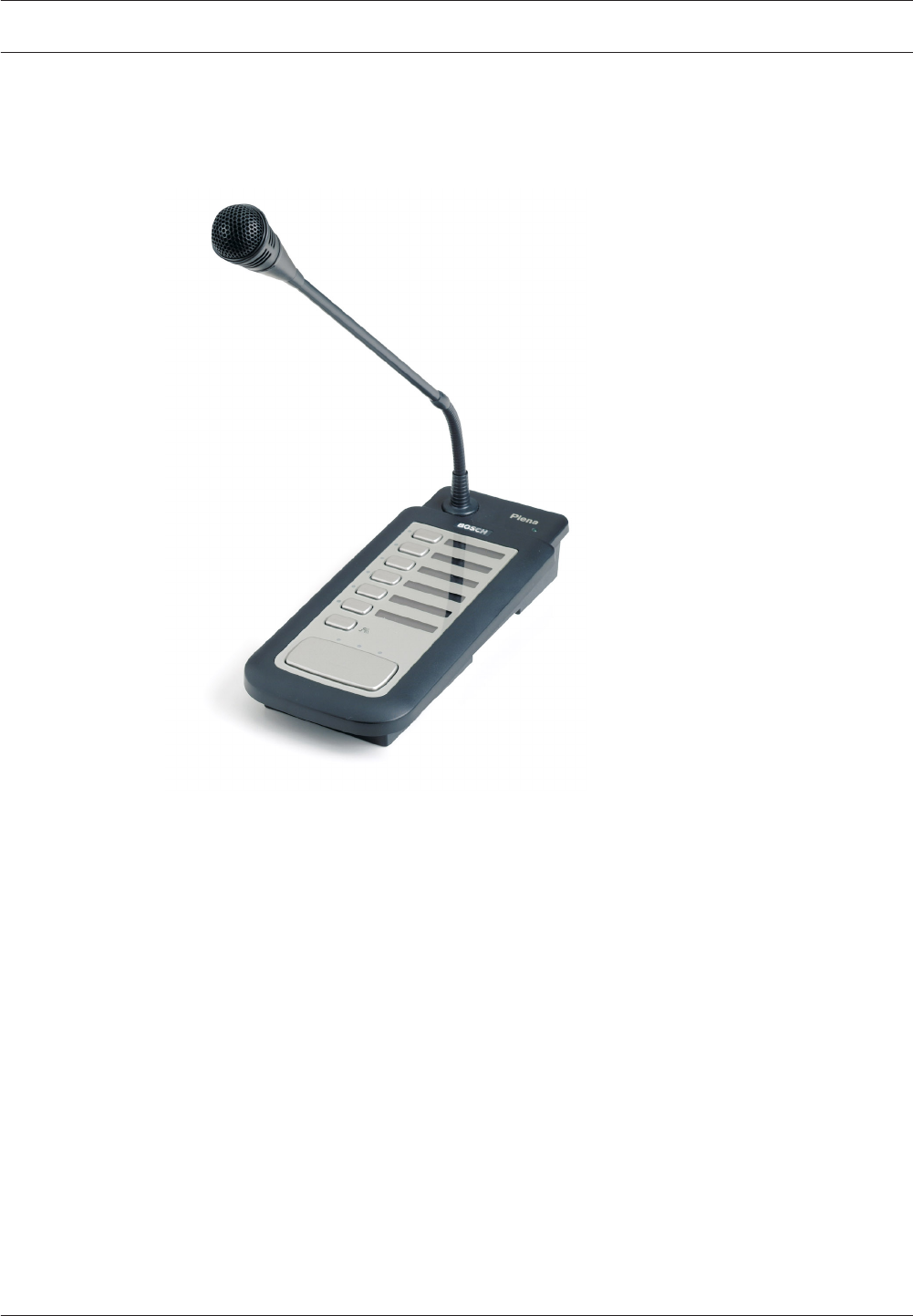
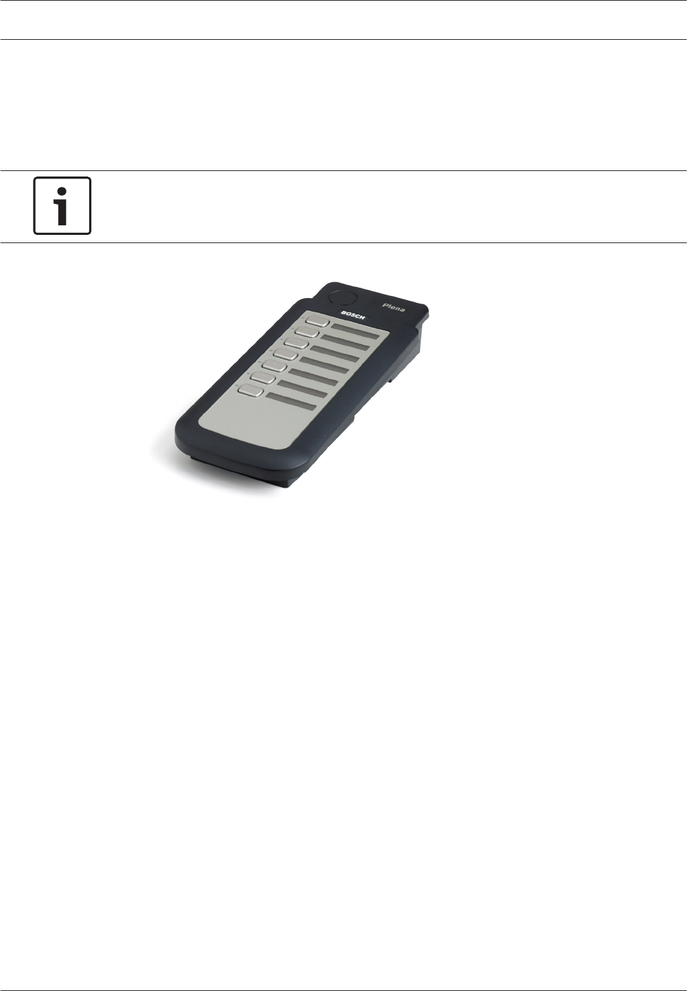
Call Station
The Call Station can be connected to the Plena Voice Alarm System to make business calls.
The maximum number of call stations in a Plena Voice Alarm System is 8.
Figure 3.5: Call Station
Buttons
Each call station has zone select buttons and a push-to-talk (PTT) button. The zone select
buttons can be configured for selecting zones and zone groups in the system. To the PTT
button, a pre and post chime can be assigned that is played at the start or at the end of the
business call.
Supervision
The call station is not supervised. For compliance to evacuation standards, the Plena Voice
Alarm System disables the call station during emergency calls.
3.4
3.4.1
3.4.2
Plena System overview | en 21
Bosch Security Systems B.V. Installation and Operation manual 2013.07 | V2.0 |
Keypad
Each voice alarm router can add 6 extra loudspeaker zones to the system. To be able to
distribute calls to the extra zones, it is possible to connect Remote Control Extension to the
call station. The maximum number of keypads that can be connected to a call station is 8, with
a maximum of 32 total in a system.
Notice!
To address zones in a 120-zone system, zone groups need to be made.
Figure 3.6: Call station keypad
3.4.3
22 en | System overview Plena
2013.07 | V2.0 | Installation and Operation manual Bosch Security Systems B.V.
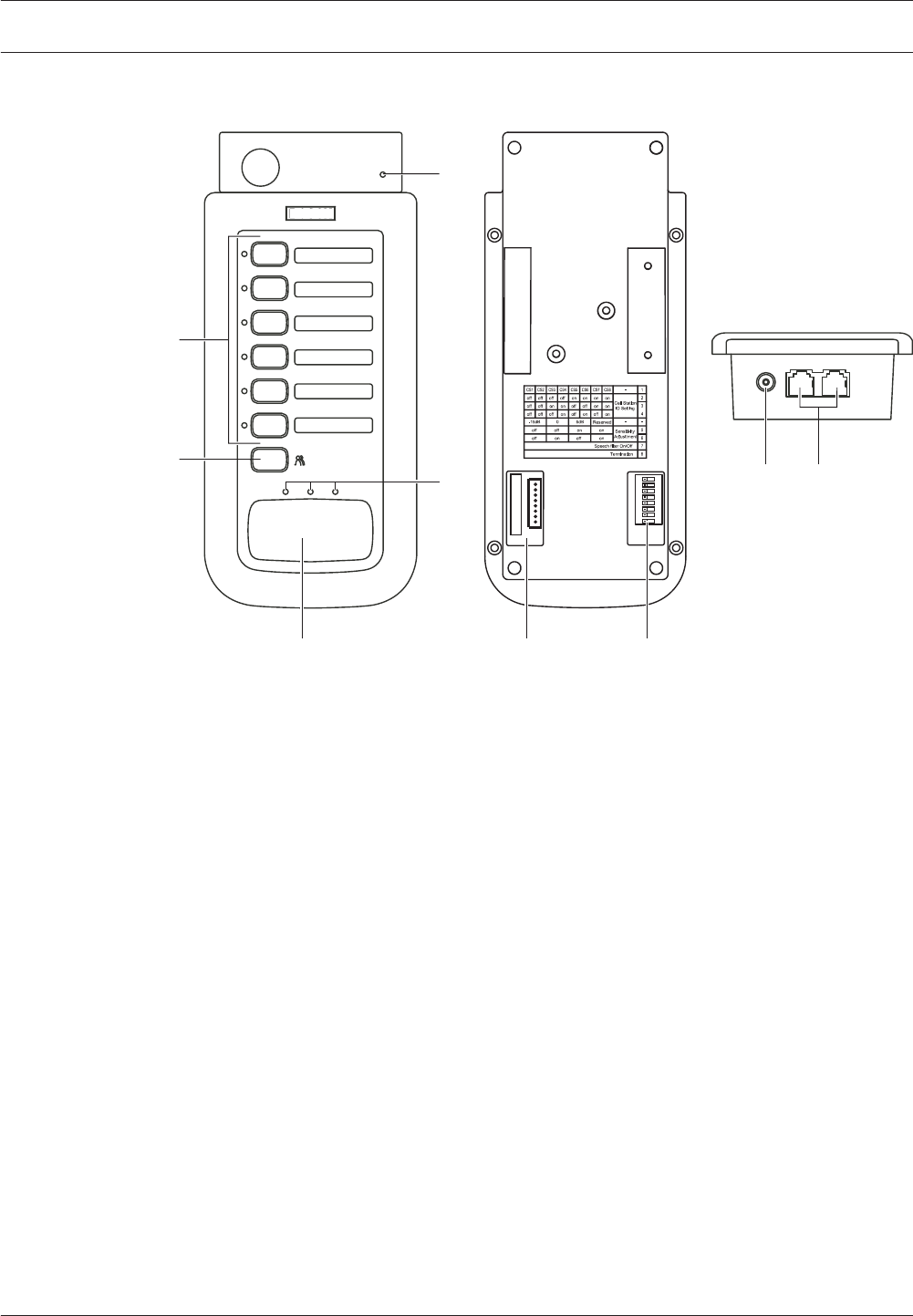
Controls, connectors and indicators
Plena
ON
1 2 3 4 5 6 7 8
2
39
5
1
4
8
6 7
Figure 3.7: Top and bottom views of the call station
Controls, indicators and connectors on the call station:
1. Power indicator:
A green LED to indicate that the call station is powered on.
2. Zone selection buttons:
Six buttons to select the zones to which the business call is distributed (see section
Business calls, page 89). Each button has a green LED, which indicates the zones to
which the business call is distributed.
3. ‘All call’ button:
A button to select all zones (see section Business calls, page 89).
4. Push-to-talk button:
A push-to-talk (PTT) button to start the business call.
5. Status indicators:
Three LEDs that indicate the status of the call station (see section Make the
announcement, page 90).
6. Keypad connector:
A connector to connect call station keypads to the call station.
7. Configuration settings:
A set of DIP switches to configure the call station (see section Call station, page 83).
8. Power supply inlet:
A socket to connect a 24 V(DC) power supply (see section Power supply, page 69).
9. System sockets:
Two redundant RJ45 sockets to connect the call station to the voice alarm controller (see
section Call station, page 50).
3.4.4
Plena System overview | en 23
Bosch Security Systems B.V. Installation and Operation manual 2013.07 | V2.0 |
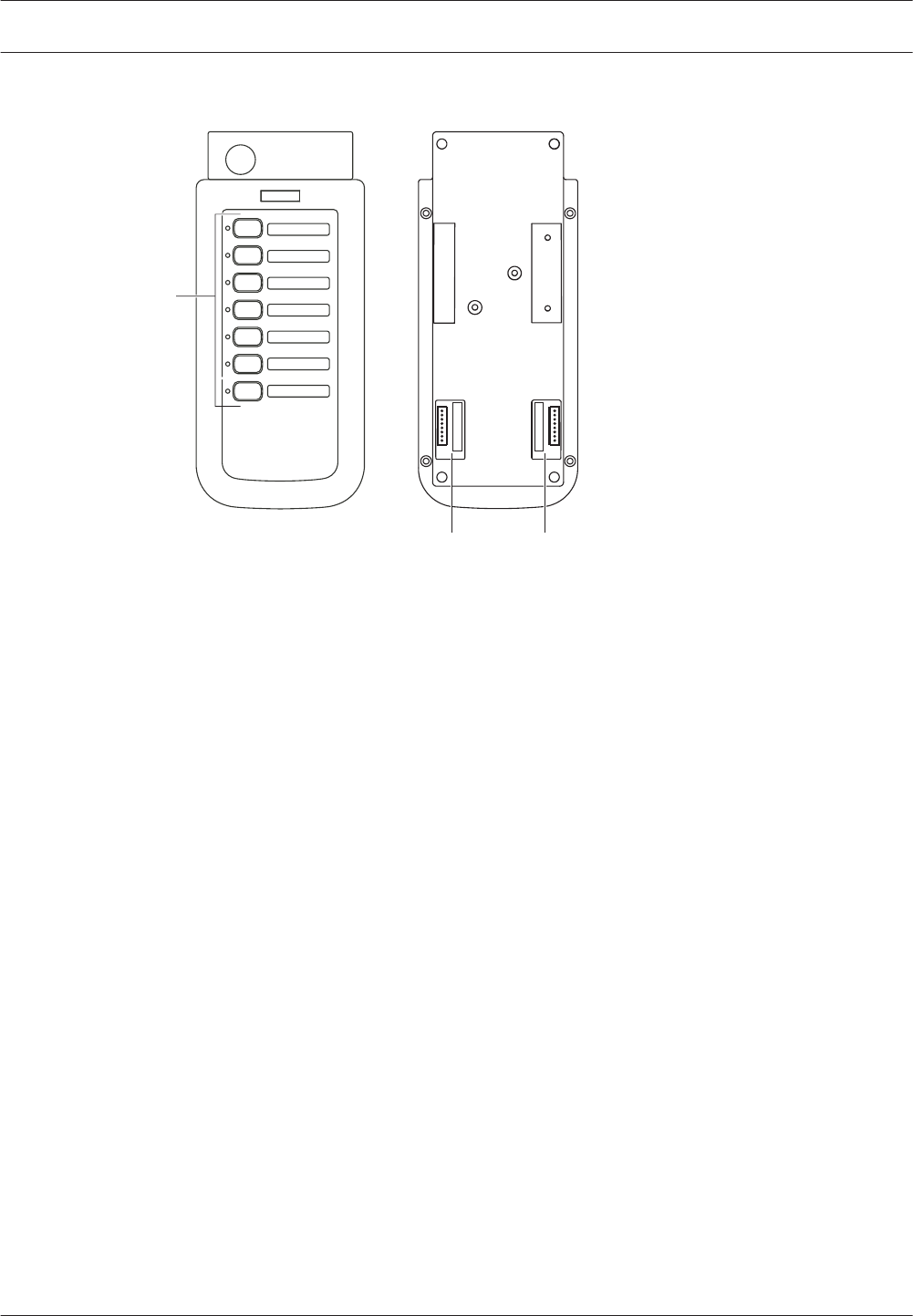
Call Station Keypad
Plena
1
2 2
Figure 3.8: Top and bottom views of the call station keypad
Controls, indicators and connectors on the call station keypad:
1. Zone selection buttons:
Seven buttons to select the zones to which the business call is distributed (see section
Business calls, page 89). Each button has a green LED, which indicates the zones to
which the business call is distributed.
2. Keypad connector:
A connector to connect call station keypads to the call station or to other call station
keypads (see section Call Station Keypad, page 44).
3.5
24 en | System overview Plena
2013.07 | V2.0 | Installation and Operation manual Bosch Security Systems B.V.
Voice Alarm Remote Control
0 dB
-6dB
-20dB
Processor reset
Network
Call/EMG
Music/Spare
Ground short
Input
Mains
Battery
Zone1
Zone2
Zone3
Zone4
Zone5
Zone6
Alarm
Zone select
Plena Voice Alarm Remote Control
Fault Indicators
Zone select
Indicator test
EMG mic
Alert message
Alarm message
All call
Zone1 Zone2 Zone3 Zone4 Zone5 Zone6
Fault EMG
Ack
Reset
AB
Disabled
Message
EMG mic
RCP
Router
Design & Quality
The Netherlands
NL-4827HG-10
Plena Voice Alarm System
RC Panel
Max. input power
300mA, 24V DC
S/N.
PLN-V6RC
A035413
Made in China
N663
8900 199 60001
12 3 4 5
69121314
15171820
710
16192122232425
811
Figure 3.9: Front and rear views of the voice alarm remote control
Controls, connections and indicators on the remote control:
1. Power LED/VU Meter:
A combined power indicator and VU meter. The green power LED is lit if the remote
control is connected to the power supply. The VU meter indicates the call level: 0 dB
(red), -6 dB, -20 dB (yellow).
2. Fault indicators:
Twelve yellow system fault LEDs (Processor reset, Network, Call/EMG, Music/Spare,
Ground short, Input, Mains, Battery, Message, EMG mic, RCP and Router) and twelve
yellow loudspeaker line fault LEDs. Fault indication is only possible if supervision is
enabled (see section Fault indicators, page 98). If supervision is disabled, the yellow
Disabled LED is lit.
3. Fault state buttons:
Two buttons to acknowledge (Ack) and reset (Reset) the fault state (see section Fault
State, page 96).
4. Emergency state buttons:
Two buttons to acknowledge (Ack) and reset (Reset) the emergency state (see section
Emergency state, page 91).
3.6
Plena System overview | en 25
Bosch Security Systems B.V. Installation and Operation manual 2013.07 | V2.0 |

5. Emergency call zone selectors:
Six buttons to select the zones to which the emergency call must be distributed (see
section Emergency state, page 91). Each button has a green and a red LED. The six red
LEDs indicate the zones that are selected for the emergency call. The six green LEDs
indicate the zones in which a business call is running.
6. BGM zone selectors:
Six buttons to select the zones to which the BGM is distributed (see section Background
music, page 88). Each button has a green LED. The six green LEDs indicate the zones to
which BGM is distributed. It is not possible to control the volume of the BGM with the
remote control.
7. All call button:
A button to select all zones. This button is only available in the emergency state (see
section Emergency state, page 91).
8. Indicator test button:
A button to test all LEDs on the front panel of the remote control and all connected
remote control extensions. All LEDs are lit as long as the button is pushed (see section
Fault State, page 96).
9. Emergency button:
A push button to put the system in the emergency state (see section Emergency state,
page 91).
10. Alert message button:
A button to select the alert message. This button is only available in the emergency state
(see section Emergency state, page 91).
11. Alarm message button:
A button to select the default alarm message. This button is only available in the
emergency state (see section Emergency state, page 91).
12. Microphone socket:
A socket to connect the hand-held emergency microphone (see section Emergency
microphone, page 49).
13. Bracket:
A bracket for the hand-held emergency microphone that is supplied with the remote
control.
14. Monitoring loudspeaker:
Built-in monitoring loudspeaker.
15. Ground:
A connection to electrically ground the remote control.
16. Firmware upgrade connector:
An RS232 connector to connect a PC to upgrade the firmware of the remote control.
17. Firmware upgrade switch:
A switch to upgrade the firmware of the remote control.
18. Remote control extension sockets:
Two redundant RJ45 sockets to connect remote control extensions to the remote control
(see section Remote control extensions, page 70).
19. Configuration settings:
A set of DIP switches to configure the remote control (see section Remote control, page
85).
20. Controller socket:
One RJ45 socket to connect the remote control to the voice alarm controller (see section
Voice alarm controller, page 70).
26 en | System overview Plena
2013.07 | V2.0 | Installation and Operation manual Bosch Security Systems B.V.

21. Emergency microphone volume control:
A rotary knob to set the volume of the hand-held emergency microphone.
22. Monitoring speaker volume control:
A rotary knob to set the volume of the monitoring loudspeaker.
23. Trigger outputs:
Three general purpose trigger outputs. For future use.
24. Status outputs:
Three status outputs to send the status of the Plena Voice Alarm System to third party
equipment (see section Status output contacts, page 70).
25. 24 V DC input:
One 24 V(DC) input to connect the remote control panel to a power supply (see section
Power, page 71).
Voice Alarm Remote Control kit
With the Voice Alarm Remote Control Kit, it is possible to make customized remote controls
that can be connected to the voice alarm controller. The remote control kit provides the same
functionality as the Voice Alarm Remote Control.
The rear panel of the remote control kit is the same as the rear panel of the Voice Alarm
Remote Control (see Voice Alarm Remote Control, page 25).
BG M Zone 1
BG M Zone 6
BG M Zone 5
BG M Zone 4
BG M Zone 3
BG M Zone 2
Ca ll Zone 6
Speak er
Pow er
EM G Ack
EM G Reset
Proce ss or r es et
Netwo rk
Ca ll /E M G.
Music /Spa re
Groun d sh or t
Input
Mains
Zone 1~ 6B
Zone 1~ 6A
RC P Ext.
Co ntrolle r/ R ou ter
EM G mic
Mess age
Ba tter y
Ca ll Z one Ind ic at or 1 ~6
EM G Zone Indi ca to r 1~ 6
GN D
BG M Zone I nd icator 1~ 6
GN D
EM G Stat e Lamp
+
_
-20dB
-6 dB
0dB
Disa ble
Alert M es sa ge
Alarm M es sa ge
EM G Mic
EM G Switch
Alert M es sa ge
Alarm M es sa ge
All cal l
Indic at or t es t
Fault A ck
Fault R es et Ca ll Z one 1
Ca ll Z one 2
Ca ll Z one 3
Ca ll Z one 4
Ca ll Z one 5
Plena Voice Alarm Remote Control Kit
LE DS / LA M P S
200mA Max . inpu t
LE DS/ LA M P S
200mA Max . inpu t
LE DS/ LA M P S
200mA Max . inpu t
Ca ll /B G M
Zone se le ct io n
GND 24V out
0.2A
5K ohm
< 5mA
24V out
LEDS/LA MPS input
1 2 3 4 5 6 1 2 3 4 5 6 1 2 3 4 5 6
1 2 3 4 5 61 2 3 4 5 6
EMG mic
External Power Supply
200mA max.
50V DC max.
Figure 3.10: Front and rear views of the remote control kit
3.7
Plena System overview | en 27
Bosch Security Systems B.V. Installation and Operation manual 2013.07 | V2.0 |
Remote Control Extension
Plena Remote Control Extension
0 dB
-6dB
-20dB
B
Processor reset
Network
Call/EMG
Music/Spare
Ground short
Input
Mains
Battery
Zone1
Zone2
Zone3
Zone4
Zone5
Zone6
Alarm
Zone select
A
Fault Indicators
Zone select
Zone1 Zone2 Zone3 Zone4 Zone5 Zone6
6
1...9
ID
1
2
3
4
5
7
9
8
RCP ext. In RCP ext. Out
Off On
Termination
Firmware
Upgrade
For service only
Off On
Warning
This apparatus must be earthed
Trigger OutputPower
24V
DC In 321
Fault
Design & Quality
The Netherlands
NL-4827HG-10
Plena Voice Alarm System
RC Panel Extension
Max. input power
200mA, 24V DC
S/N.
PLN-V6RCE
A035413
Made in China
N663
8900 199 80001
NC
NO
COM
12 3
4
567910 8111213
Figure 3.11: Front and rear views of the remote control extension
Overview of the controls, indicators and connectors on the remote control extension:
1. Power LED/VU Meter:
A combined power indicator and VU meter. The green power LED is lit if the remote
control extension is connected to the mains or back-up power and switched on. The VU
meter indicates the call level: 0 dB (red), -6 dB, -20 dB (yellow).
2. Fault indicators:
Eight yellow system fault LEDs (Processor reset, Network, Call/EMG, Music/Spare,
Ground short, Input, Mains, Battery) and twelve yellow loudspeaker line fault LEDs. Fault
indication is only possible if supervision is enabled (see section Fault indicators, page
98).
3. Emergency call zone selectors:
Six buttons to select the zones to which the emergency call must be distributed (see
section Emergency state, page 91). Each button has a green and a red LED. The six red
LEDs indicate the zones that are selected for the emergency call. The six green LEDs
indicate the zones in which a business call is running.
4. BGM zone selectors:
Six buttons to select the zones to which the BGM is distributed (see section Background
music, page 88). Each button has a green LED. The six green LEDs indicate the zones to
which BGM is distributed.
5. Ground:
A connection to electrically ground the remote control extension.
6. Firmware upgrade connector:
An RS232 connector to connect a PC to upgrade the firmware of the remote control
extension.
3.8
28 en | System overview Plena
2013.07 | V2.0 | Installation and Operation manual Bosch Security Systems B.V.
7. Firmware upgrade switch:
A switch to upgrade the firmware of the remote control extension.
8. System sockets:
One RJ45 socket to connect the remote control extension to the remote control (see
section Remote control extensions, page 70).
9. Configuration settings:
A termination switch for the Remote Control Extension and 0-9 / 10-19 switch (see
section Remote control extension, page 86).
10. Remote control extension ID:
A rotary switch to set the ID of the remote control extension (see section Remote control
extension, page 86).
11. Trigger outputs:
Three general purpose trigger outputs. For future use.
12. Status output:
One status output to send the status of the Plena Voice Alarm System to third party
equipment (see section Status output contacts, page 73).
13. 24 V DC input:
One 24 V(DC) input to connect the remote control panel to a power supply (see section
Power, page 73).
Remote Control Extension kit
With the Voice Alarm Control Extension Kit, it is possible to make customized remote control
extensions that can be connected to a remote control (Fireman’s Panel, Remote Control,
Remote Control kit). The remote control extension kit provides the same functionality as the
Voice Alarm Remote Control Extension.
The rear panel of the remote control extension kit is the same as the rear panel of the Voice
Alarm Remote Control Extension (see Remote Control Extension, page 28).
BG M Zone 1
BG M Zone 6
BG M Zone 5
BG M Zone 4
BG M Zone 3
BG M Zone 2
Ca ll Z one 6
Ca ll Z one 1
Ca ll Z one 2
Ca ll Z one 3
Ca ll Z one 4
Ca ll Z one 5
Pow er
-16d B
-6 dB
0dB
Proce ss or r es et
Netwo rk
Ca ll /E M G
Music /Spa re
1 2 3 4 5 6
Zone 1~ 6A Zone 1~ 6B
Ba tter y
Mains
Input
Groun d sh or t
EM G Zone
Indic at or 1 ~6
GN D Cal l Zo ne
Indic at or 1 ~6
GN D BG M Zone
Indic at or 1 ~6
Plena Voice Alarm Remote Control Extension Kit
GN D
Ca ll /B G M
Zone se le ct io n
LE DS / LA M P S
200mA Max . inpu t
LE DS / LA M P S
200mA Max . inpu t
1 2 3 4 5 6 1 2 3 4 5 6 1 2 3 4 5 6 1 2 3 4 5 6
Figure 3.12: Front and rear views of the remote control extension kit
3.9
Plena System overview | en 29
Bosch Security Systems B.V. Installation and Operation manual 2013.07 | V2.0 |
Fireman’s Panel
Plena Fireman's Panel
EMG mic
Fault Indicators
Processor reset
Network
Call/EMG
Music/Spare
Ground short
Input
A
B
A
B
A
B
Zone1
Zone2
Zone3
Disable
For service only
On
1
2
Termination
RCP ID
Controller
Monitoring
Speaker Warning
This apparatus must be earthed
Trigger Output
24V
DC In
NC
NO
COM
Call Fault EMG
321
Power
NC
NO
COM
NC
NO
COM
EMG.
Mic
Monitor
Off
On
Off
Firmware
Upgrade
Emergency
Acknowledge
Emergency
Reset
Fault
Acknowledge
Fault Reset
Emergency
Mains
Battery
Message
EMG mic
RCP
Router
A
B
A
B
A
B
Zone4
Zone5
Zone6
Indicator test
Reserve
Monitor Speaker
Call Alarm
Message
Design & Quality
The Netherlands
NL-4827HG-10
Plena Voice Alarm System
Fireman's Panel
Max. input power
300mA, 24V DC
S/N.
PLN-V1FP
A035413
Made in China
N663
8900 199 70501
0 dB
-6dB
-20dB
12 3 4 5 6 7 8
9
10121315 1114
1617
181920
Figure 3.13: Front and rear views of the fireman’s panel
Overview of the controls, connections and indicators on the fireman’s panel:
1. Power LED/VU Meter:
A combined power indicator and VU meter. The green power LED is lit if the fireman’s
panel is connected to the power supply. The VU meter indicates the call level: 0 dB (red),
-6 dB, -20 dB (yellow).
2. Emergency button:
A push button to put the system in the emergency state (see section Emergency state,
page 91).
3. Emergency acknowledge:
A push button to acknowledge the emergency state (see section Emergency state, page
91).
4. Emergency reset:
A push button to reset the emergency state (see section Emergency state, page 91).
5. Alarm message button:
A push button to start the default alarm message. This button is only available in the
emergency state (see section Emergency state, page 91).
6. Fault acknowledge:
A push button to acknowledge the fault state (see section Fault State, page 96).
3.10
30 en | System overview Plena
2013.07 | V2.0 | Installation and Operation manual Bosch Security Systems B.V.

7. Fault reset:
A push button to reset the fault state (see section Fault State, page 96).
8. Fault indicators:
Twelve yellow system fault LEDs (Processor reset, Network, Call/EMG, Music/Spare,
Ground short, Input, Mains, Battery, Message, EMG mic, RCP and Router) and twelve
yellow loudspeaker line fault LEDs. Fault indication is only possible if supervision is
enabled (see section Fault indicators, page 98). If supervision is disabled, the yellow
Disabled LED is lit.
9. Indicator test button:
A button to test all LEDs on the front panel of the fireman’s panel and all connected
remote control extensions. All LEDs are lit as long as the button is pushed (see section
Fault State, page 96).
10. Ground:
A connection to electrically ground the fireman’s panel.
11. Firmware upgrade connector:
An RS232 connector to connect a PC to upgrade the firmware of the fireman’s panel.
12. Firmware upgrade switch:
A switch to upgrade the firmware of the fireman’s panel.
13. Remote control extension sockets:
Two redundant RJ45 sockets to connect remote control extensions to the fireman’s panel
(see section Remote control extensions, page 70).
14. Configuration settings:
A set of DIP switches to configure the fireman’s panel (see section Remote control, page
85).
15. Controller socket:
One RJ45 socket to connect the fireman’s panel to the voice alarm controller (see section
Voice alarm controller, page 70).
16. Emergency microphone volume control:
A rotary knob to set the volume of the hand-held emergency microphone.
17. Monitoring speaker volume control:
A rotary knob to set the volume of the monitoring loudspeaker.
18. Trigger outputs:
Three general purpose trigger outputs. For future use.
19. Status outputs:
Three status outputs to send the status of the Plena Voice Alarm System to third party
equipment (see section Status output contacts, page 74).
20. 24 V DC input:
One 24 V(DC) input to connect the fireman’s panel to a power supply (see section Power,
page 74).
Plena System overview | en 31
Bosch Security Systems B.V. Installation and Operation manual 2013.07 | V2.0 |

End Of Line detection board
The End Of Line (EOL) detection board makes a continuous check of the integrity of the
loudspeaker line based on a pilot tone. This check is in addition to the check given by the
impedance measurement. The pilot tone is independent of the quantity of the loudspeakers in
the system or the load on the speaker cables.
The EOL is installed in the speaker cabinet at the furthest point on a loudspeaker line. When
the EOL detects a pilot tone that is given by the voice alarm system, the loudspeaker lines
have no fault. The EOL trigger output is closed and the LED lights up to show that the lines
have a pilot tone signal.
If the loudspeaker cable has a fault, the pilot tone stops. The EOL circuit becomes open,
which is detected by the Voice Alarm Controller.
One EOL board can be installed to give a single fault indication per zone or more than one can
be installed on a single fault input to check the integrity of a loudspeaker line with several
branches. When more than one EOL board is installed, the configuration is called a daisy-
chain.
When a fault is detected by the Voice Alarm Controller, to find the EOL board that detects the
failure, every individual board must be checked.
Application examples
Schools
Schools are typical example of applications with a large number of zones each with a relatively
low output power requirement per zone. The main priorities are speech intelligibility and
compliance with IEC 60849 standard (or equivalent). In addition to mandatory voice alarm
functionality for evacuating staff and students, EVAC systems for schools should also include
chime tones for notifying the start/finish of lessons, plus public address functionality for
individually calling classrooms or public area. BGM is not essential. Since a classroom has a
low ambient noise level, 1 loudspeaker is usually sufficient, keeping the total power
requirement relatively low. Outside areas such as playgrounds and sports fields will require
weatherproof horn loudspeakers.
Summary of requirements
– Typically 20 to 60 zones (in high schools)
– Speech intelligibility is the main priority
– Low power requirement (1 loudspeaker) per classroom
– Fireman’s panel by main entrance
– Call station in main office
– Additional public address functions such as chime tones desirable
– BGM in recreation areas is optional
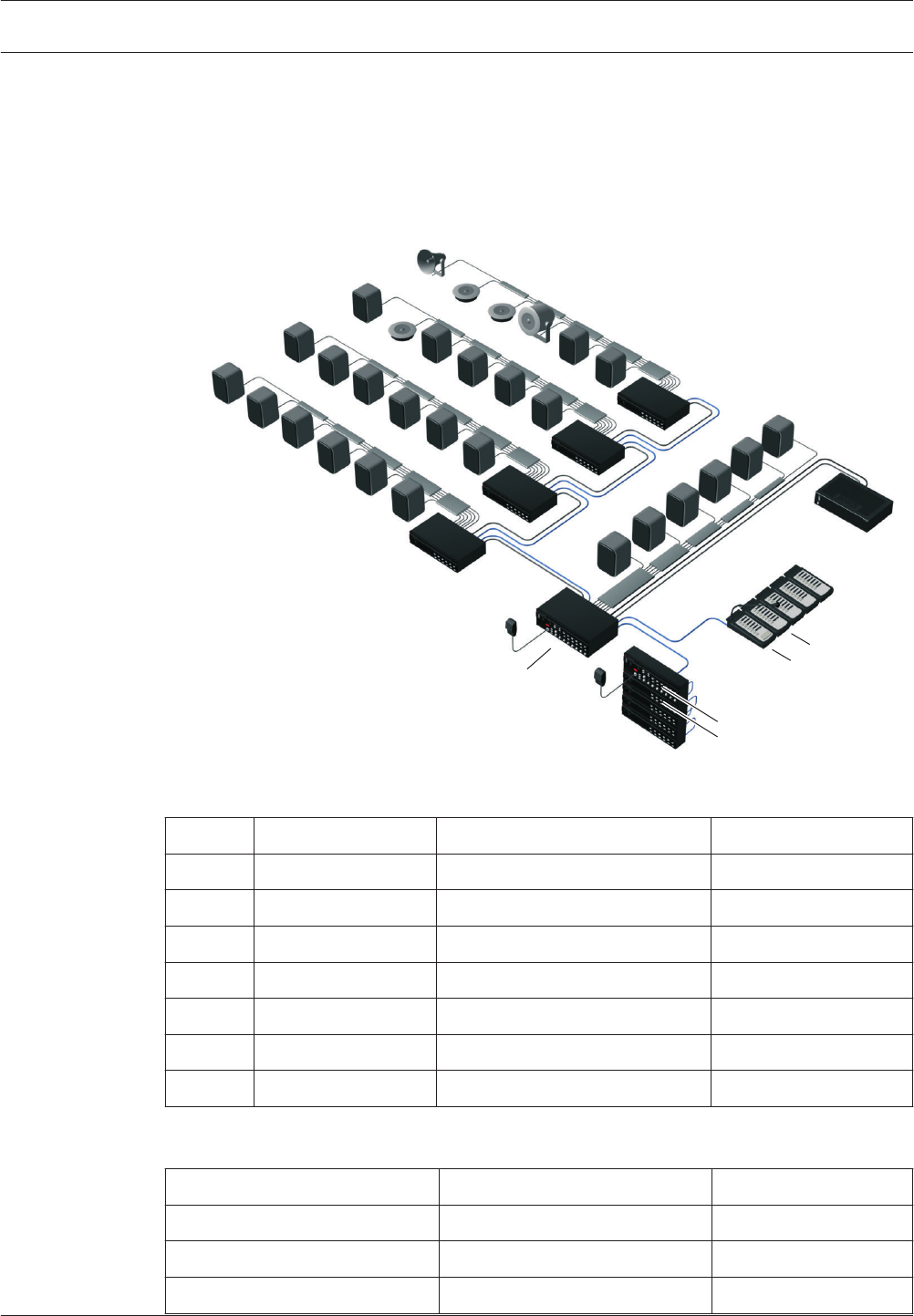
Solution for a 30-zone system
The Plena Voice Alarm System Controller handles message routing to 6 zones, the remaining
24 zones require four additional 6-zone routers. The office is equipped with a call station plus
keypads for individually addressing zones, while a fireman’s panel (with overall priority) is
built in by the main entrance.
Power requirements
The system controller features a built‑in 240 W power amplifier, making it possible to drive up
to 40 loudspeakers with a power handling capacity of 6 W each. This is sufficient for a
medium-sized high school with 24 classrooms, 4 toilets/changing rooms, a staff meeting room
3.11
3.12
3.12.1
32 en | System overview Plena
2013.07 | V2.0 | Installation and Operation manual Bosch Security Systems B.V.
and 2 offices, each requiring a single loudspeaker. The canteen, assembly hall, playing fields
and corridors typically require more loudspeakers per zone. An additional Plena Power
Amplifier is used as a spare amplifier.
Layout
2
Z7-12
Z13-18
Z19-24
Z25-30
Z1-6
7
5
3
4
6
1
Figure 3.14: Example of a school
Number Unit Description No.
1 LBB 1990/00 Controller 1 x
2 LBB 1992/00 Router 4 x
3 LBB 1996/00 Remote control 1 x
4 LBB 1997/00 Remote control extension 4 x
5 LBB 1956/00 Call station 1 x
6 LBB 1957/000 Call station keypad 4 x
7 LBB 1935/20 Power Amplifier (240 W) 1 x
Table 3.1: Units
Zone Description Power
Z1-22 Classrooms 22 x 6 W
Z23 Toilets/changing rooms 4 x 6 W
Z24 Staff meeting room 1 x 6 W
Plena System overview | en 33
Bosch Security Systems B.V. Installation and Operation manual 2013.07 | V2.0 |

Zone Description Power
Z25-26 Offices 2 x 6 W
Z27 Corridors 4 x 6 W
Z28 Assembly hall 2 x 6 W
Z29 Lunch canteen 2 x 6 W
Z30 Playing fields 1 x 10 W
Total 232 W
Table 3.2: Zones
34 en | System overview Plena
2013.07 | V2.0 | Installation and Operation manual Bosch Security Systems B.V.

Swimming pool
Swimming pools and other indoor sports and recreational facilities are typical examples of
smaller applications with few zones. The main priorities are excellent speech intelligibility and
compliance with IEC 60849 standard (and its national equivalents), although music in different
areas is optional. An EVAC system for a swimming pool requires voice alarm functionality with
public address functionality for regular announcements and background music (optional). To
ensure that all visitors in the relatively noisy pool area hear emergency messages, the power
output for that zone is relatively high. Other areas, such as the changing rooms and offices,
have lower power requirements.
Summary of requirements
– Typically up to 6 zones
– Speech intelligibility is the main priority
– High power requirement in the noisy pool area
– Fireman’s panel by fire exit
– Call station in office/reception
– Additional public address functions for announcements
– BGM
Solution for a 5-zone system
The Plena Voice Alarm System controller handles routing to up to 6 zones, so no additional
routers are required. The office/reception is equipped with a call station plus keypad for
individually addressing zones, while a fireman’s panel (with overall priority) is built‑in by the
emergency exit. The Plena Voice Alarm System is a two-channel system, so BGM can still be
provided in zones not receiving a call.
Power requirements
The system controller has a built-in 240 W power amplifier, making it possible to drive up to
40 loudspeakers with a power handling capacity of 6 W each. The pool area requires high
power music loudspeakers qualified for use in a high humidity atmosphere. The snack bar
uses cabinet loudspeakers for music reproduction. The zones are defined as indicated in the
table. An additional Plena Power Amplifier is used for two-channel operation and as a spare
amplifier.
3.12.2
Plena System overview | en 35
Bosch Security Systems B.V. Installation and Operation manual 2013.07 | V2.0 |
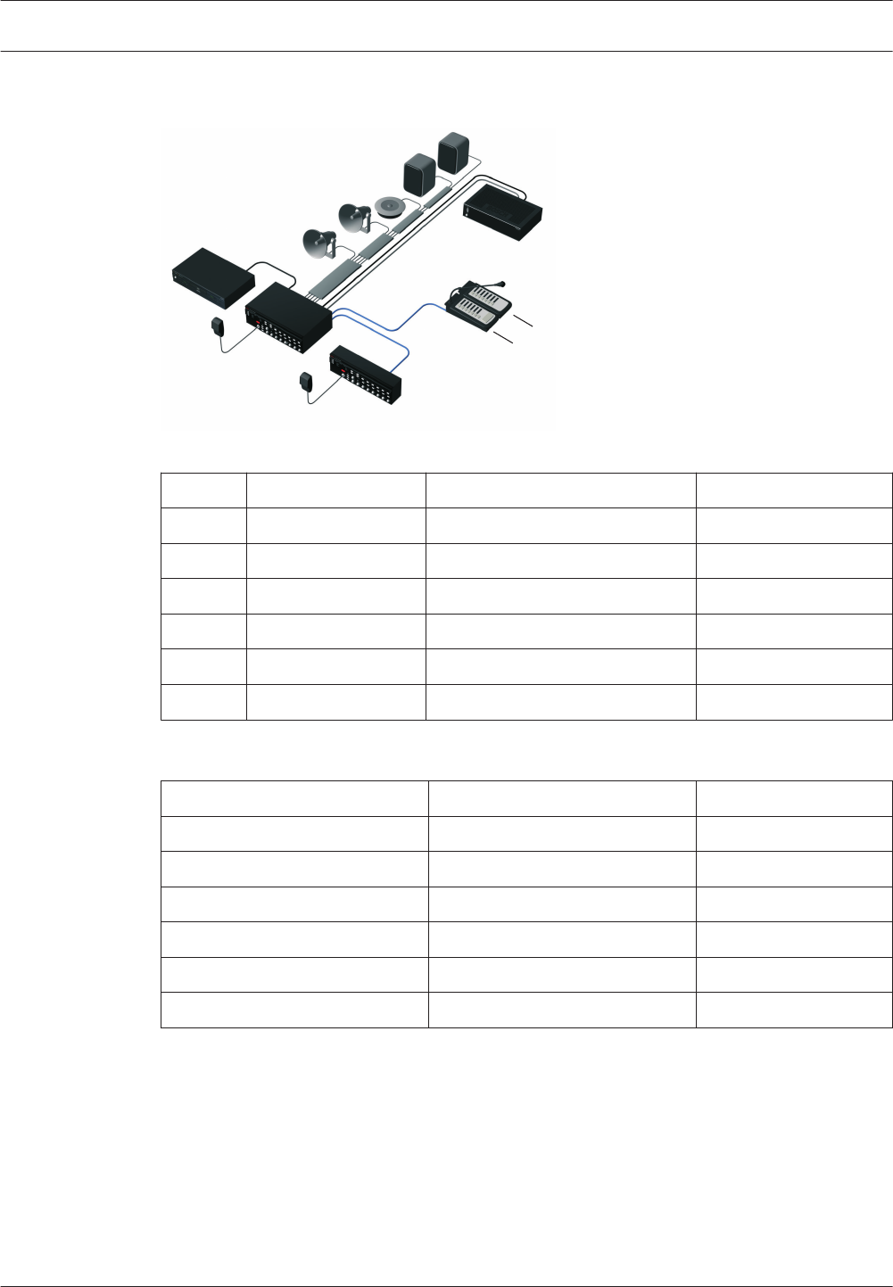
Layout
6
1
Z1-5
5
3
2
4
Figure 3.15: Example of a swimming pool
Number Unit Description No.
1 LBB 1990/00 Controller 1 x
2 LBB 1996/00 Remote control 1 x
3 LBB 1956/00 Call station 1 x
4 LBB 1957/00 Call station keypad 4 x
5 LBB 1935/20 Power Amplifier (240 W) 1 x
6 Bosch Music source 1 x
Table 3.3: Units
Zone Description Power
Z1 Indoor pool area 5 x 30 W
Z2 Children’s pool area 2 x 10 W
Z3 Changing rooms 4 x 6 W
Z4 Snack-bar 4 x 6 W
Z5 Office 2 x 6 W
Total 230 W
Table 3.4: Zones
36 en | System overview Plena
2013.07 | V2.0 | Installation and Operation manual Bosch Security Systems B.V.

Shopping mall
Shopping malls are typical example of applications with a large number of zones with varying
output power requirements per zone. The priorities are speech intelligibility and compliance
with IEC 60849 standard (and its national equivalents). In addition to mandatory voice alarm
functionality for evacuating the public and shop personnel, an EVAC system for shopping
centers can have BGM for the public areas. It should be possible to individually call each shop
or store. During emergency messages, each shop’s BGM volume control is automatically
overridden. Additional public address functionality for making general public announcements
is an optional requirement.
Summary of requirements
– Typically up to 60 zones
– Speech intelligibility is the main priority
– Variable power requirement per zone
– Call station in security control room
– Additional public address functionality (non-emergency)
– BGM in public areas
– BGM music with local override in shops
Solution for a 54-zone system
A Plena Voice Alarm System Controller handles routing to 6 zones, the remaining 48 zones
require eight 6‑zone routers. The security control room is equipped with a remote control
panel and call station plus keypads for individually addressing zones and BGM for the public
areas, while the controller unit and routers are located in a fire-resistant cabinet or basement.
Fireman’s panel (with overall priority) is built-in close to the main entrance or emergency exit
(subject to relevant local regulations). The Plena Voice Alarm System is a two-channel system,
so BGM can still be provided in zones not receiving a call.
Power requirements
Each zone will have varying power requirements, ranging from small shops with a single
loudspeaker to department stores with several floors and more loudspeakers. Parking garages
and open-air walkways will require weatherproof sound projectors or horn loudspeakers. To
facilitate phased evacuation from different levels of the shopping center, public areas are
divided into zones. Additional Plena Power Amplifiers are incorporated to provide additional
power, two-channel operation and for use as a spare amplifier.
3.12.3
Plena System overview | en 37
Bosch Security Systems B.V. Installation and Operation manual 2013.07 | V2.0 |
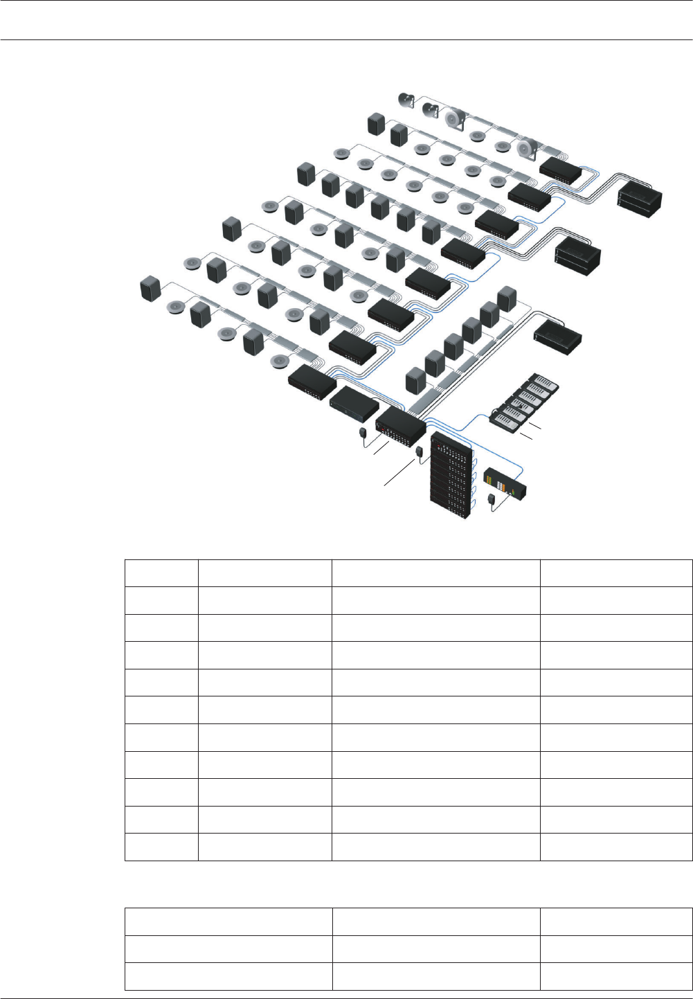
Layout
2
Z49-54
Z43-48
Z37-42
Z31-36
Z25-30
Z19-24
Z13-18
Z7-12
Z1-6
9
8
8
6
3
7
10
1
4
5
Figure 3.16: Example of a shopping mall
Number Unit Description No.
1 LBB 1990/00 Controller 1 x
2 LBB 1992/00 Router 8 x
3 LBB 1995/00 Fireman’s Panel
4 LBB 1996/00 Remote control 1 x
5 LBB 1997/00 Remote control extension 8 x
6 LBB 1956/00 Call station 1 x
7 LBB 1957/00 Call station keypad 5 x
8 LBB 1935/20 Power Amplifier (240 W) 3 x
9 LBB 1938/20 Power Amplifier (480 W) 2 x
10 Bosch Music source 1 x
Table 3.5: Units
Zone Description Power
Z1-30 30 small shops/kiosks 30 x 6 W
Z31-36 6 shops 12 x 6 W
38 en | System overview Plena
2013.07 | V2.0 | Installation and Operation manual Bosch Security Systems B.V.

Zone Description Power
Z37-42 6 medium-sized stores 24 x 6
Z47 Security control room 1 x 6 W
Z48 Offices 4 x 6 W
Z49 Walkways ground floor 4 x 6 W
Z50 Gallery 1st floor 10 x 6 W
Z51 Gallery 2nd floor 10 x 6 W
Z52 Main public square 4 x 18 W
Z53 Parking garage level 1 6 x 10 W
Z54 Parking garage level 2 6 x 10 W
Total 858 W
Table 3.6: Zones
Plena System overview | en 39
Bosch Security Systems B.V. Installation and Operation manual 2013.07 | V2.0 |

Hotel
Smaller hotels are typical examples of applications with relatively few zones, each with a
medium to high output power requirement. The priorities are speech intelligibility and
compliance with IEC 60849 standard. In addition to mandatory voice alarm functionality for
evacuating guests and staff, an EVAC system for a hotel should also include BGM in the
restaurant, bar and lobby, plus public address functionality for general paging. To ensure that
all guests hear an emergency message, the power output per zone is relatively high. Outside
areas such as car parking garages, require weatherproof horn loudspeakers.
Summary of requirements
– Typically 10 to 20 zones in small hotels
– Speech intelligibility is the main priority
– High power requirement (multiple loudspeakers) per floor
– Fireman’s panel by fire exit
– Call stations in reception and office
– Additional public address functions for paging guests
– BGM in lobby and restaurant
Solution for a 12-zone system
A Plena Voice Alarm System Controller handles routing to up to 6 zones, the additional 6
zones require a router. Both the reception and office are equipped with call stations plus
keypads for individually addressing zones, while a fireman’s panel (with overall priority) is
built‑in by the emergency exit. The Plena Voice Alarm System is a two‑channel system, so BGM
can still be provided in zones not receiving a call.
Power requirements
The system controller features a built-in 240 W power amplifier, able to drive up to 40
loudspeakers (6 W). Additional Plena Power Amplifiers are incorporated to provide additional
power, two‑channel operation and spare amplification. To facilitate phased evacuation from
different floors of the hotel, guest areas are divided into separate zones, each fitted with 13
ceiling loudspeakers in the corridors. The bar uses cabinet loudspeakers, while the parking
garage uses weatherproof horn loudspeakers.
3.12.4
40 en | System overview Plena
2013.07 | V2.0 | Installation and Operation manual Bosch Security Systems B.V.
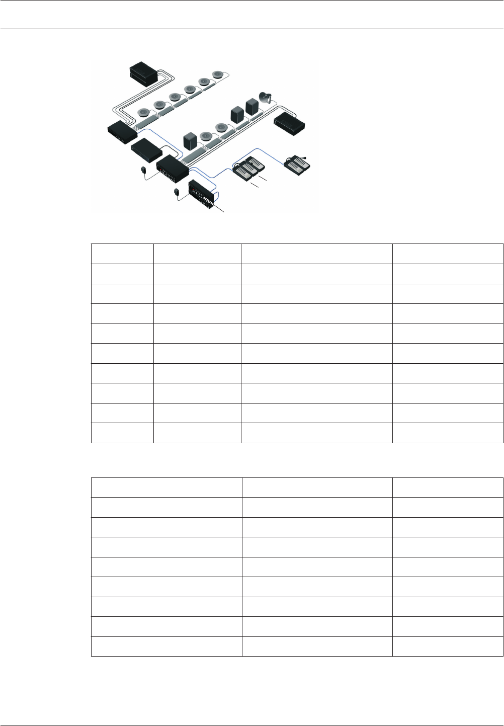
Layout
2
9
1
Z7-12
Z1-6
7
8
5
3
6
4
Figure 3.17: Example of a hotel
Number Unit Description No.
1 LBB 1990/00 Controller 1 x
2 LBB 1992/00 Router 1 x
3 LBB 1996/00 Remote control 1 x
4 LBB 1997/00 Remote control extension 1 x
5 LBB 1956/00 Call station 2 x
6 LBB 1957/00 Call station keypad 3 x
7 LBB 1935/20 Power Amplifier (240 W) 1 x
8 LBB 1938/20 Power Amplifier (480 W) 2 x
9 Bosch Music source 1 x
Table 3.7: Units
Zone Description Power
Z1 Bar 3 x 6 W
Z2 Restaurant 6 x 6 W
Z3 Lobby 2 x 6 W
Z4 Office 1 x 6 W
Z5 Kitchens 2 x 6 W
Z6 Parking garage 3 x 10 W
Z7-12 Floors 1 to 6 78 x 6 W
Total 582 W
Table 3.8: Zones
Plena System overview | en 41
Bosch Security Systems B.V. Installation and Operation manual 2013.07 | V2.0 |

Calls and priorities
As the Plena Voice Alarm System is a public address and emergency sound system, it is used
to distribute background music, business calls and emergency calls.
Priority
To each call, a priority is assigned. When two or more calls are addressed to the same zone or
need shared resources (e.g. the internal message manager of the voice alarm controller), the
call with the lower priority is stopped immediately and the call with the higher priority is
started. The priority of a call depends on the part of the system that started the call and must
be configured with the configuration software.
Notice!
See the Configuration Software Manual for more information about the configuration
software.
When two or more calls with the same priority are addressed to the same zone or need shared
resources (e.g. the internal message manager of the voice alarm controller), the oldest call is
stopped immediately and the youngest call is started. An exception to this rule are mergeable
messages (see section Mergeable messages, page 42).
Mergeable messages
When two or more calls are started that are based on the same mergeable message template
and have the same priority, the calls are merged. The youngest call will not stop the oldest call
in this case. Mergeable message can be created with the configuration software.
Business call
A business call is a call that is made when the system is in the normal state. Business calls
always have a priority between 2 and 8 and can be started with:
– Business trigger inputs
– Call stations
– The mic/line input with VOX functionality of the voice alarm controller
Emergency call
An emergency call is a call that is made when the system is in the emergency state. Emergency
calls have a certain priority in the configuration software, and can be started with:
– Emergency trigger inputs (priority between 2 and 14)
– The hand-held emergency microphone of the voice alarm controller (priority between 9
and 19)
– The mic/line input with VOX functionality of the voice alarm controller (priority between 2
and 14)
3.13
3.13.1
3.13.2
3.13.3
3.13.4
42 en | System overview Plena
2013.07 | V2.0 | Installation and Operation manual Bosch Security Systems B.V.
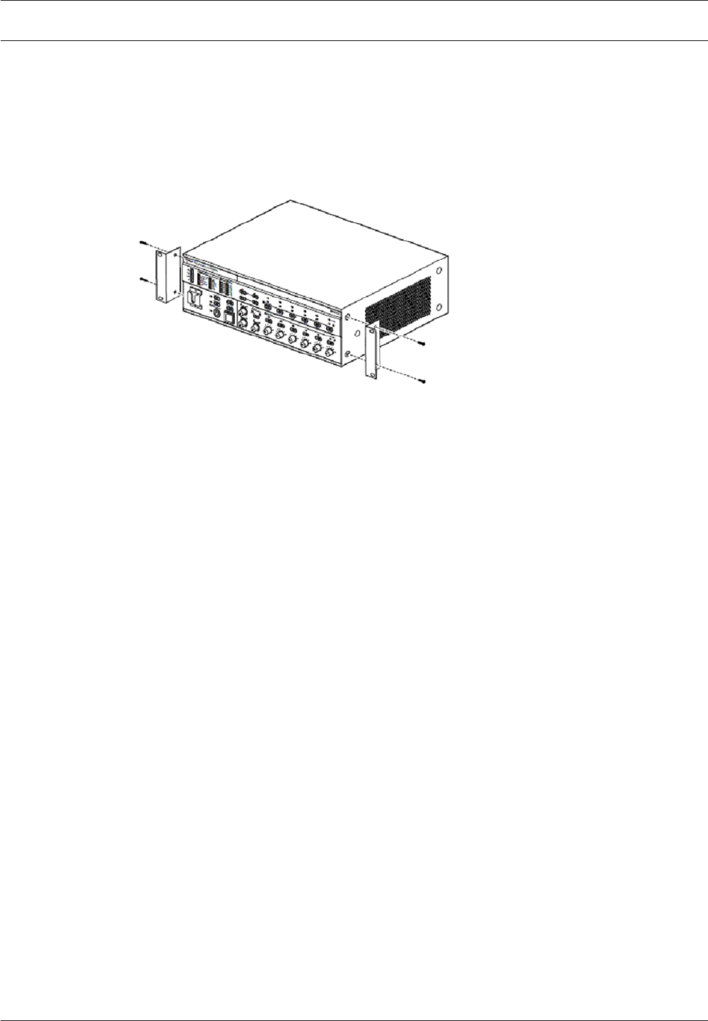
Installation
Voice Alarm Controller
The voice alarm controller is suitable for table‑top and 19‑inch rack-mounting installation. Two
brackets for rack-mounting are supplied.
Figure 4.1: Brackets for rack-mounting
Make sure that there is a free space of at least 100 mm on both sides of the unit for
ventilation. The voice alarm controller has an internal fan, which is regulated to keep the
temperature inside the unit within the safe operating area.
Voice Alarm Router
The voice alarm router is suitable for table‑top and 19‑inch rack mounting installation. Two
brackets for rack-mounting are supplied. Installing a voice alarm router is similar to installing a
voice alarm controller (see section Voice Alarm Controller, page 43).
4
4.1
4.2
Plena Installation | en 43
Bosch Security Systems B.V. Installation and Operation manual 2013.07 | V2.0 |
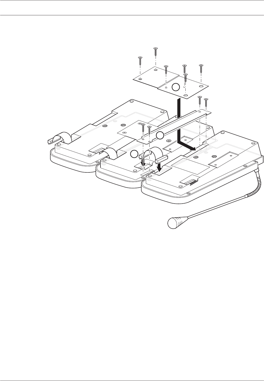
Call Station Keypad
Call station keypads can be connected to call stations or to other call station keypads.
11 22 44
33 55 66 77
1
2
3
Figure 4.2: Connecting call station keypads
Voice Alarm Remote Control
The remote control is suitable for table‑top and 19‑inch rack mounting installation. Two
brackets for rack-mounting are supplied. Installing a remote control is similar to installing a
voice alarm controller (see section Voice Alarm Controller, page 43). The brackets can also be
used to attach the remote control to a wall.
Voice Alarm Remote Control Kit
The remote control kit is suitable for table‑top and 19‑inch rack mounting installation. Two
brackets for rack-mounting are supplied. Installing a remote control kit is similar to installing a
voice alarm controller (see section Voice Alarm Controller, page 43).
4.3
4.4
4.5
44 en | Installation Plena
2013.07 | V2.0 | Installation and Operation manual Bosch Security Systems B.V.

Remote Control Extension
The remote control extension is suitable for table‑top and 19‑inch rack mounting installation.
Two brackets for rack-mounting are supplied. Installing a remote control extension is similar
to installing a voice alarm controller (see section Voice Alarm Controller, page 43). The
brackets can also be used to attach the remote control extension to a wall.
Remote Control Extension Kit
The remote control extension kit is suitable for table‑top and 19‑inch rack mounting
installation. Two brackets for rack-mounting are supplied. Installing a remote control kit is
similar to installing a voice alarm controller (see section Voice Alarm Controller, page 43).
End Of Line detection board
To install an EOL, use these general notes:
– An EOL board can only be installed in a 2‑channel system. The EOL board needs the
second amplifier to produce the pilot tone for the zones that are not in use. Refer to
section 2-Channel mode operation, page 78.
– The volume control on the VAC must be set to -9 dB or higher. The recommended setting
is 0 dB. A lower dB setting attenuates the pilot‑tone.
Notice!
You must use either EOL or impedance measurement, not both.
Notice!
Do not connect the EOL board to the secondary side of a volume control.
The secondary side of a volume control can attenuate the pilot tone.
All inputs to a VAC or router that have an EOL input must be normally closed inputs. The EOL
board operates with a normally closed output and the configuration software is set to Action
Open. Use another router to receive normally open inputs.
Notice!
During a call the pilot tone is absent in zones without a call or without background music. The
LED on the EOL board is dim. The EOL input is ignored during calls to avoid false fault
readings.
The short circuit check must be set in the configuration software.
Notice!
The EOL board detects a short circuit, but the EOL cannot detect where the short circuit is.
Notice!
It is possible for the LED to turn off before the contact is opened or vice versa. This level
difference is typically less than 500 mV.
4.6
4.7
4.8
Plena Installation | en 45
Bosch Security Systems B.V. Installation and Operation manual 2013.07 | V2.0 |
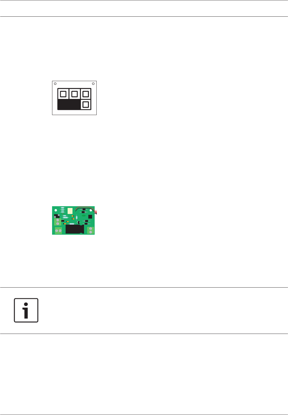
Installation of a single EOL
1. Connect the two cables at the end of the 100 V loudspeaker line to the Input 100 V LS on
the EOL board.
2. Connect the two cables from an Emergency Trigger Input on the Voice Alarm Controller to
TRGA on the EOL.
3. Connect the jumpers JP1 on the EOL as shown.
Figure 4.3: JP1 for single EOL
Installation of a multiple EOL in a daisy-chain
With a daisy‑chain configuration it is possible to:
– Supervise several loudspeaker lines with only one fault input.
– Supervise several branches of a loudspeaker line with just one fault input.
1. Connect the cable from the 100 V loudspeaker line to the terminal 100 V LS Input on the
EOL board.
2. Connect one cable from an Emergency Trigger Input on the Voice Alarm Controller to the
FIRST BOARD input on the EOL board.
JP1
Figure 4.4: JP1 for first EOL
3. Connect a 20 or 22 kOhm resistor in parallel with the Trigger input to connect more than
one EOL board on a single Trigger input and to supervise them.
4. Connect the EOL boards to the Trigger input as indicated previousl. This input should be
on the Controller or Router to which the loudspeaker lines it supervises are also
connected
Notice!
The last EOL board in line is connected in a different way than the other EOL boards. This is
required to supervise the whole EOL detection line against short circuit. Such a short circuit
will be reported as an Input Fault. A break in the detection line will be reported as a Line
Fault, just as a loudspeaker line failure.
4.8.1
4.8.2
46 en | Installation Plena
2013.07 | V2.0 | Installation and Operation manual Bosch Security Systems B.V.
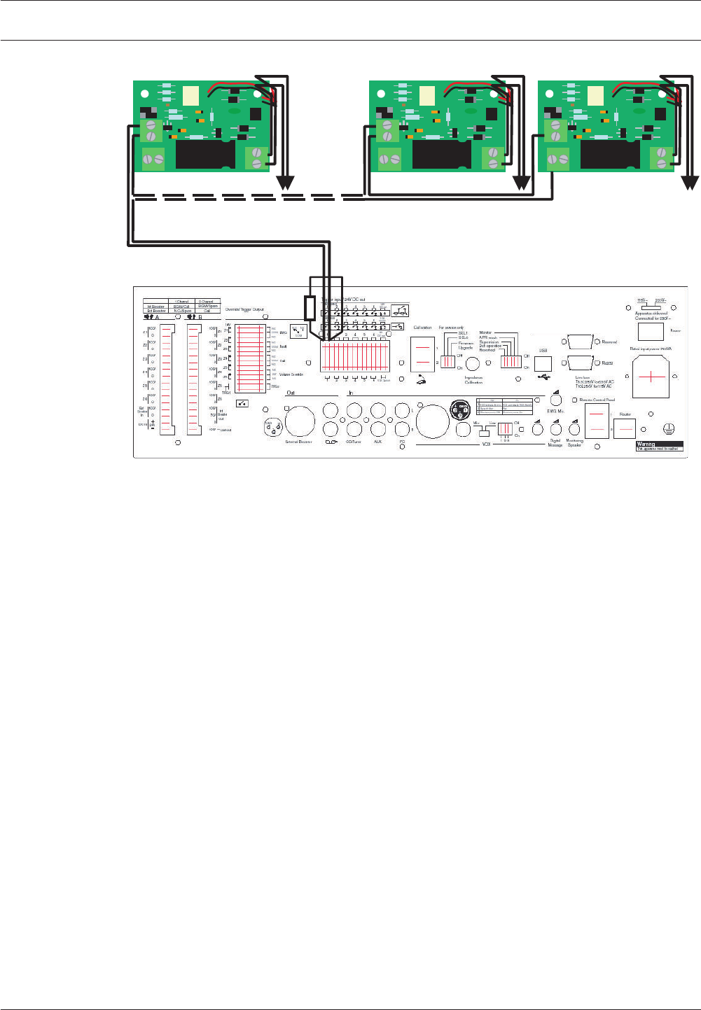
JP1
JP1
JP1
Last EOL board
First EOL board
20k
Figure 4.5: Trigger input indication
5. In the configuration program, set the Action Programming for the relevant input to Fault
and EOL.
6. Enter the Zone or Zone group that is monitored by the EOL board. The Zone group can be
All Zones (of the Controller/Router), Zone 1‑3 or Zone 4‑6. Fault Type and Zone will
define the visual indication on the unit in case of a fault.
7. Set the Action to Open and Type to Momentary.
Plena Installation | en 47
Bosch Security Systems B.V. Installation and Operation manual 2013.07 | V2.0 |
Dummy load
To install the Dummy load do as follows:
1. Connect the two leads onto the connection terminals of the last loudspeaker in a line.
2. Attach the Dummy Load circuit board in the loudspeaker cabinet to the mounting studs.
Notice!
In some loudspeakers only one mounting stud is available as the studs are too far apart.
Set the jumper JP1 on the Dummy load
The Dummy load incorporates the following functions:
– Increases the percentage of impedance (with respect to the cable impedance) present at
the end of the line.
– Allows more loudspeakers to be fitted.
– Allows longer cable lengths.
Fault detection of the loudspeaker lines with impedance measurement is triggered by a
change in excess of 20%. The impedance at the end of the loudspeaker line must be more
than 20% of the total impedance to make sure that an open circuit is detected.
The Dummy Load has a jumper to set the load at 20 kHz to 8, 20 and 60 W.
Notice!
You can download the Dummy load calculator.xls from the Plena Voice Alarm System product
related information on www.boschsecurity.com.
1. Use the Dummy load calculator to calculate the jumper setting of JP1 on the Dummy load.
2. Select the Excel sheet Dummy load calculator. Click Enable Macros when the dialog box
appears. The worksheet opens.
3. Type the load per loudspeaker in Step 1. The maximum number of loudspeakers is
automatically calculated and appears in Step 2.
4. Type the number of loudspeakers in the line in Step 2. The result automatically appears in
Step 3.
5. Type the capacitance of the 100 V cable in Step 4.
6. Type the length of the cable in Step 5.
7. Click Display jumper JP1 settings. The configuration of the jumper settings appears.
8. Set the jumper JP1 on the Dummy load to the shown in the calculator.
4.9
4.9.1
48 en | Installation Plena
2013.07 | V2.0 | Installation and Operation manual Bosch Security Systems B.V.
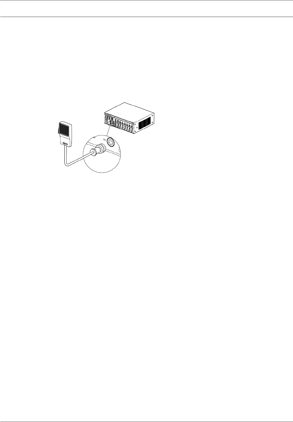
Connection
Voice Alarm Controller
Emergency microphone
The voice alarm controller has 1 connector for an emergency microphone. A hand-held
emergency microphone is supplied with the voice alarm controller. See for installation details
below. Turn the lock ring clockwise to lock the plug.
Figure 5.1: Connecting the emergency microphone
5
5.1
5.1.1
Plena Connection | en 49
Bosch Security Systems B.V. Installation and Operation manual 2013.07 | V2.0 |
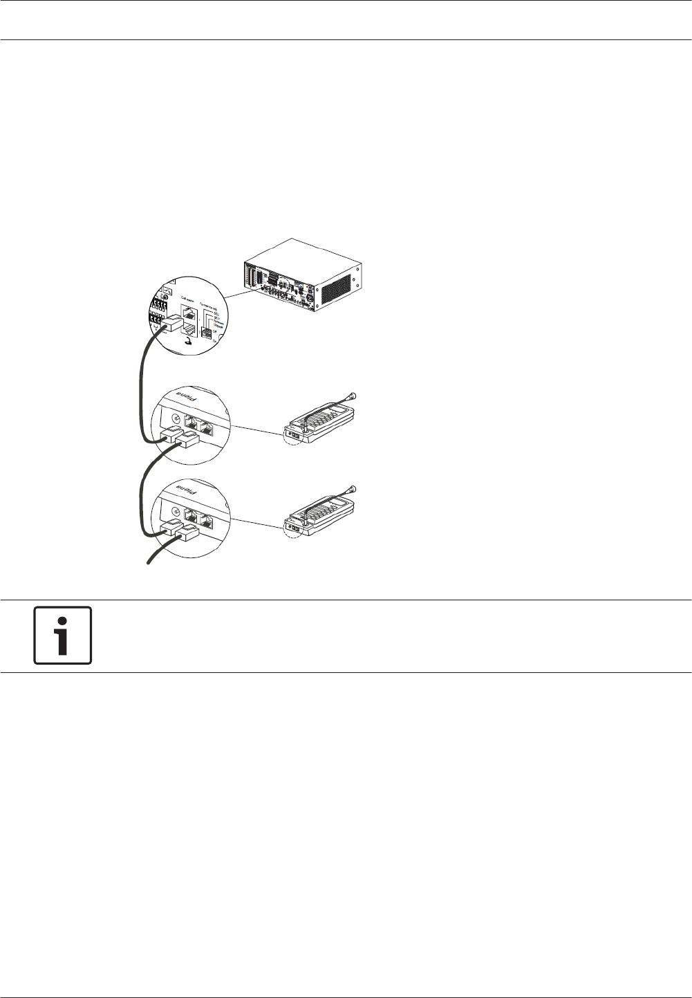
Call station
The voice alarm controller has 2 sockets for Call Stations. Use CAT‑5 Ethernet cables with
RJ45 plugs to connect call stations to the voice alarm controller. When the system requires
more than 2 call stations, use the system sockets on the call stations to make loop-throughs.
See the connection details below.
The controller comes with CAN bus termination installed. This is an RJ45 connector with
built‑in termination. Make sure that it is installed in the unused connector. On the routers and
call station the termination switch setting must be in the "ON" position on the last device.
Figure 5.2: Connecting call stations
Notice!
Each connected call station must have a unique ID (see section Call station, page 83).
If the cable between the call station and the voice alarm controller is too long to power the
call station, it is possible to connect a 24 VDC power source (see section Power supply, page
69).
5.1.2
50 en | Connection Plena
2013.07 | V2.0 | Installation and Operation manual Bosch Security Systems B.V.
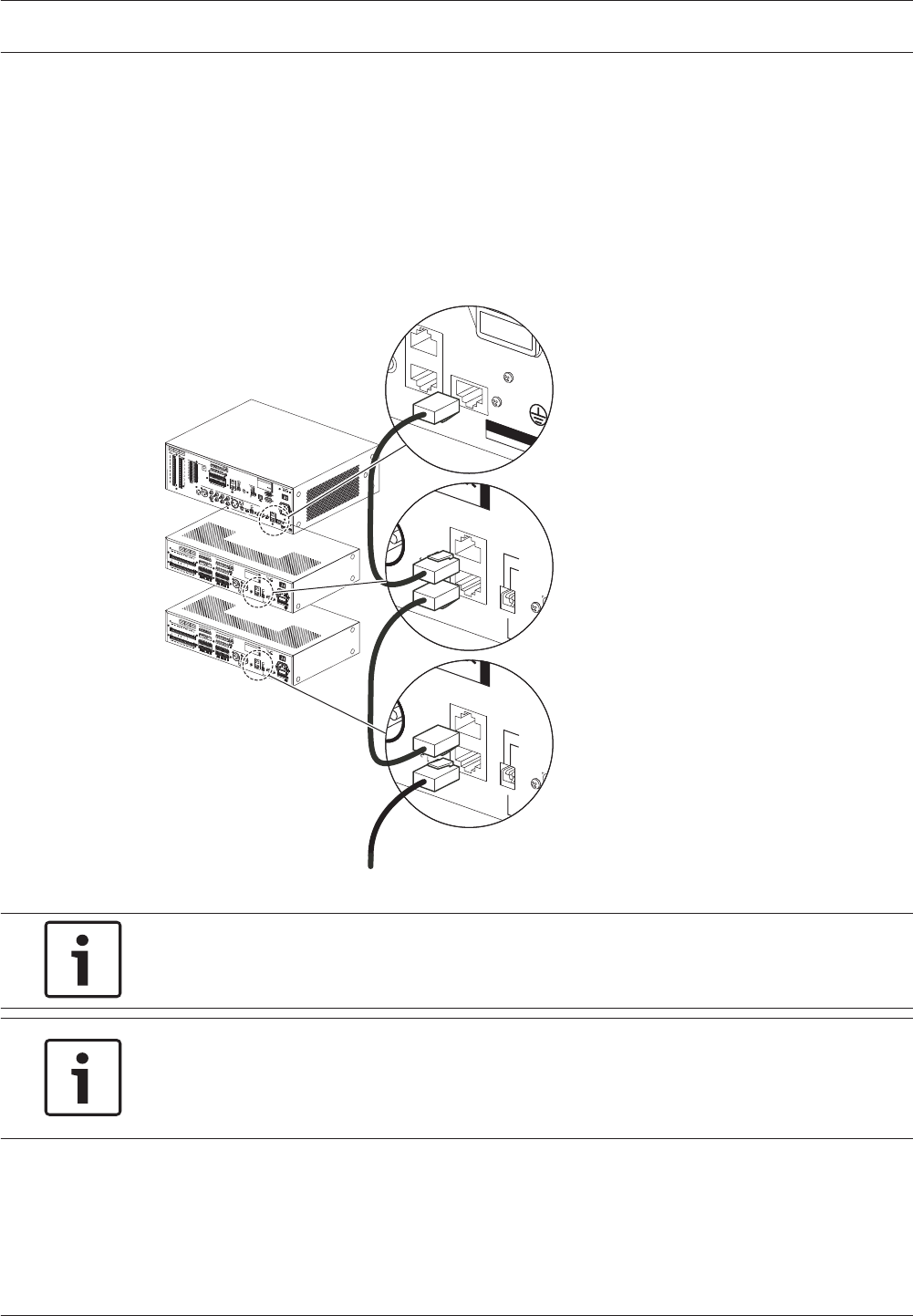
Voice alarm routers
The voice alarm controller has 1 socket for Voice Alarm Routers. Use shielded CAT‑5 Ethernet
cables with RJ45 plugs to connect a voice alarm router to the voice alarm controller. When the
system requires more than 1 voice alarm router, use the system sockets on the voice alarm
router to make loop-throughs. See the connection details below.
The router come with CAN bus termination installed. This is an RJ45 connector with built‑in
termination. Make sure that it is installed in the unused connector. On the routers and call
station the termination switch setting must be in the "ON" position on the last device.
Monitoring
Speaker
ontrol Panel
Router
Warning
This apparatus must be earthed
1
2
Firmware upgrade
Design & Quality
The Netherlands
N663
Termination
1...9
ID
Router
Rated input power
Line fuse
Booster 2
In
Out
Made in China
On
Off
Firmware upgrade
Design & Quality
The Netherlands
N663
Termination
1...9
ID
Router
Rated input power
Line fuse
Booster 2
In
Out
Made in China
On
Off
Figure 5.3: Connecting routers
Notice!
Each connected voice alarm router must have a unique ID (see section Voice alarm router,
page 82).
Notice!
The voice alarm controller comes delivered with termination plugs (connectors) fitted in some
RJ45 sockets. When connecting routers and RCP panels, the connected device must have
their termination set to on, and the termination plug has to plugged in the unused socket.
5.1.3
Plena Connection | en 51
Bosch Security Systems B.V. Installation and Operation manual 2013.07 | V2.0 |
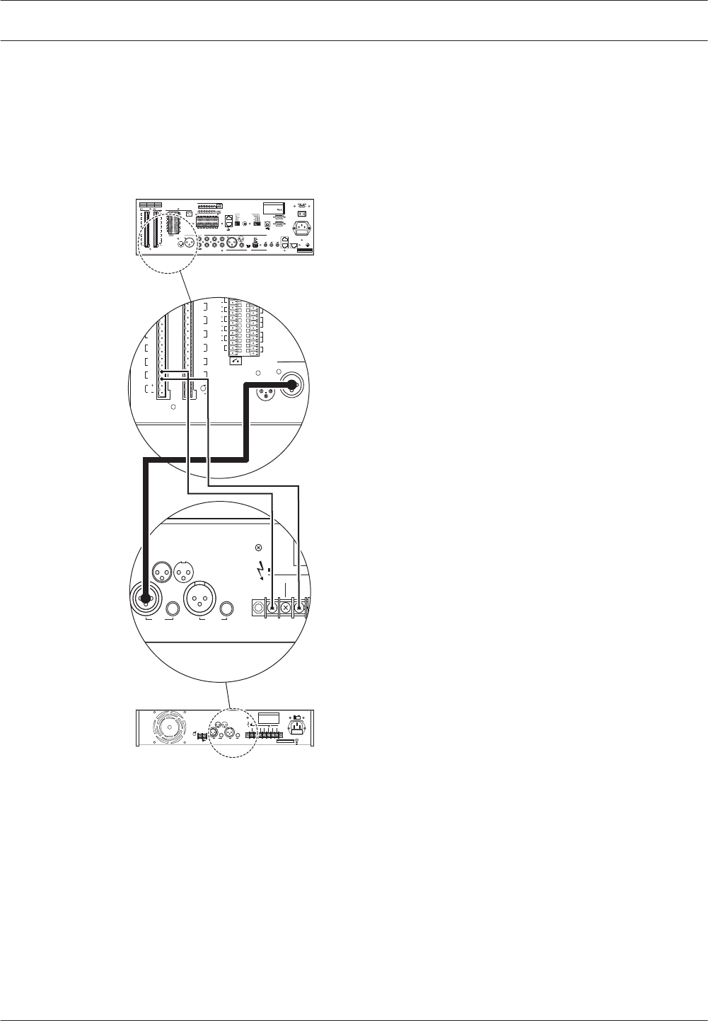
External power amplifier
The voice alarm controller has 1 external power amplifier output (line level, 1 V) and 1 external
power amplifier input (100 V) to connect an external power amplifier. The function of the
external power amplifier (e.g. a Plena Power Amplifier 360/240W) depends on the channel
mode for which the voice alarm controller is configured (see section 1-Channel mode
operation, page 77 and section 2-Channel mode operation, page 78).
100V 70V 0 0
line in line out
1 2
3
1 2
3
GND GND+ +
- -
COM
NC
TRG2
Z2
Z3
Z4
Z5
Z6
Ext
Booster
In
DC In
0
TRG 1
Int
Booster
Out
24V
Fault
Call
External Booster
Out
100V
0
100V
0
100V
0
100V
0
100V
0
100V
0
24V
70V
Z2
Z3
Z4
Z5
Z6
GND
NC
COM
NO
NC
COM
NO
NO
100V
0
Call out
0
100V
0
100V
0
100V
0
100V
0
100V
0
Z2
Z3
Z4
Z5
Z6
NO
Volume Override
100V
Figure 5.4: Connecting an external power amplifier
5.1.4
52 en | Connection Plena
2013.07 | V2.0 | Installation and Operation manual Bosch Security Systems B.V.
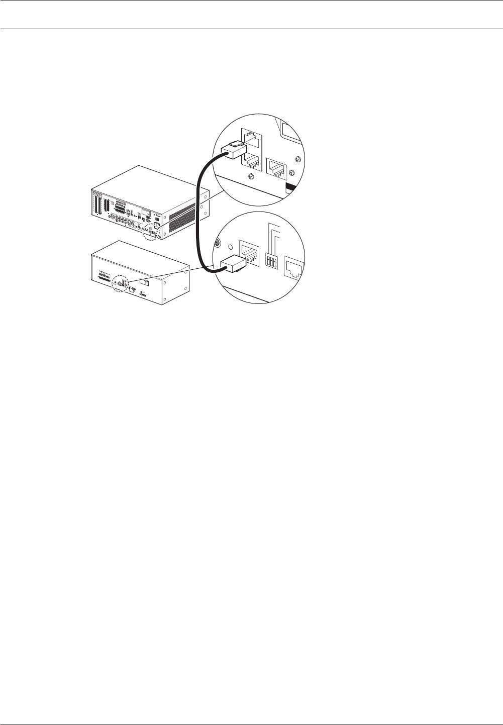
Remote controls
The voice alarm controller has 2 sockets for remote controls. Use shielded CAT‑5 Ethernet
cables with RJ45 plugs to connect a remote control to the voice alarm controller. See the
connection details below:
Monitoring
Speaker
Control Panel
Router
Warning
This apparatus must be earthed
1
2
Controller
Off
Termination
Monitor
RCP ID
RCP extension
EMG.
Mic
On
1
2
Design & Quality
The Netherlands
Plena Voice Alarm System
RC Panel
Max. input power
300mA, 24V DC
S/N.
V6RC
A035413
63
Figure 5.5: Connecting a remote control
5.1.5
Plena Connection | en 53
Bosch Security Systems B.V. Installation and Operation manual 2013.07 | V2.0 |
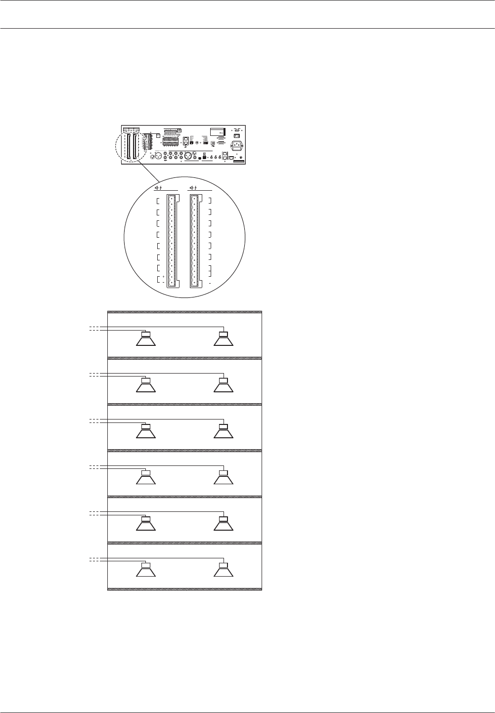
Loudspeakers
The voice alarm controller has 6 zone outputs (Z1 to Z6). Each zone output consists of 2
redundant loudspeaker lines (line A and line B). Normally, calls and BGM are distributed to a
zone over both loudspeaker lines. If one of the loudspeaker lines of a zone fails, it is still
possible to distribute calls and BGM to the zone over the remaining loudspeaker line.
Z1
Z2
Z3
Z4
Z5
Z6
Ext
Booster
In
DC In
100V
0
Int
Booster
Out
100V
0
100V
0
100V
0
100V
0
100V
0
100V
0
24V
70V
100V
0
Call out
100V
0
100V
0
100V
0
100V
0
100V
0
100V
0
Z2
Z3
Z4
Z5
Z6
Z1
A B
Int B BG M/
100V
1A 1B
2A 2B
3A 3B
4A 4B
5A 5B
6A
Z6
Z5
Z4
Z3
Z2
Z1
6B
Figure 5.6: Connecting loudspeaker zones
5.1.6
54 en | Connection Plena
2013.07 | V2.0 | Installation and Operation manual Bosch Security Systems B.V.

If it is necessary to detect the removal or failure of a single loudspeaker, the following is
advised:
– Do not connect more than 5 loudspeakers to the same loudspeaker line (line A or line B).
Field tests have shown that the impedance of loudspeakers and loudspeaker lines varies
with temperature and age. The limit of 5 loudspeakers is set due to this variation. In a
more stable environment, the number of loudspeakers can be higher.
– Make sure that all loudspeakers connected to the same loudspeaker line have the same
impedance.
Notice!
The impedance measurement of the Plena Voice Alarm System has an accuracy better than
2%. The system only generates a fault if the line impedance difference is greater than the
configured accuracy. Use the configuration software to configure the accuracy
Notice!
See the Configuration Software Manual for more information about the configuration
software.
Notice!
The maximum load for the internal power amplifier of the voice alarm controller is 240 W.
However, if the voice alarm controller is used in 2‑channel mode and an external 480 W
amplifier is connected to it, the maximum loudspeaker load can be 480 W at 100 V. This is
because in 2‑channel mode, the internal power amplifier of the voice alarm controller is used
for BGM only and distributes BGM at ‑3 dB, from which follows that the maximum power
output is 240 W at 70 V and that the loading caused by 100 V loudspeakers at 70 V is also
240 W. The external amplifier is used for calls only with 480 W output power and 100 V
loudspeaker line voltage.
Notice!
The voice alarm system has great flexibility, from one amplifier for all routers to one amplifier
per router, or any arrangement in between. But in a 2‑channel system, the number and type
of amplifiers for the call-channel has to be exactly mirrored for the music channel. Getting the
signal from the same routers and feeding loudspeaker signal to the same set of routers. If not,
amplifier supervision and amplifier sparing will not function properly.
Plena Connection | en 55
Bosch Security Systems B.V. Installation and Operation manual 2013.07 | V2.0 |
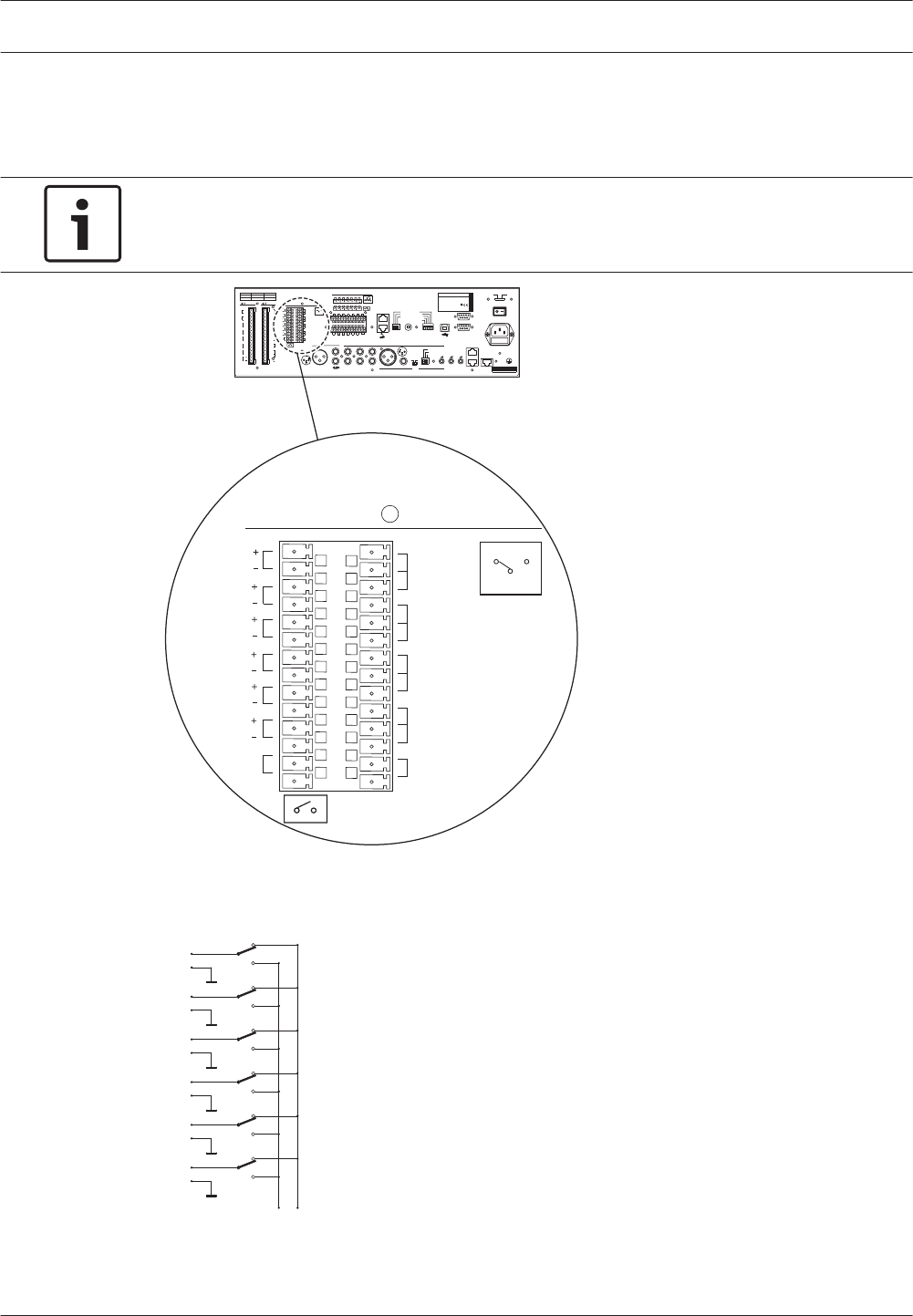
Volume overrides
The voice alarm controller has 6 override outputs; 1 for each zone in the system. These are
suitable for 4‑wire override (24 V) and 3‑wire override.
Notice!
By default, the voice alarm controller is configured for 4‑wire (24 V), power-saving override
(refer to situation I below).
COM
NC NO
NC
TRG2
Override/Trigger Output
TRG 1
24V
EMG
Fault
Call
Z1
Z2
Z3
Z4
Z5
Z6
NC
COM
NO
NC
COM
NO
NC
COM
NO
NO
24V
Volume Override
Figure 5.7: Override outputs
Internally, the positive override pins (Z+) are all connected to either the NC or the NO contact
of the Volume Override output. The negative override pins (Z-) are all connected to earth.
Z1 +
_
Z2 +
_
Z3 +
_
Z4 +
_
Z5 +
_
Z6 +
_
NO NC
Figure 5.8: Volume override contacts
5.1.7
56 en | Connection Plena
2013.07 | V2.0 | Installation and Operation manual Bosch Security Systems B.V.
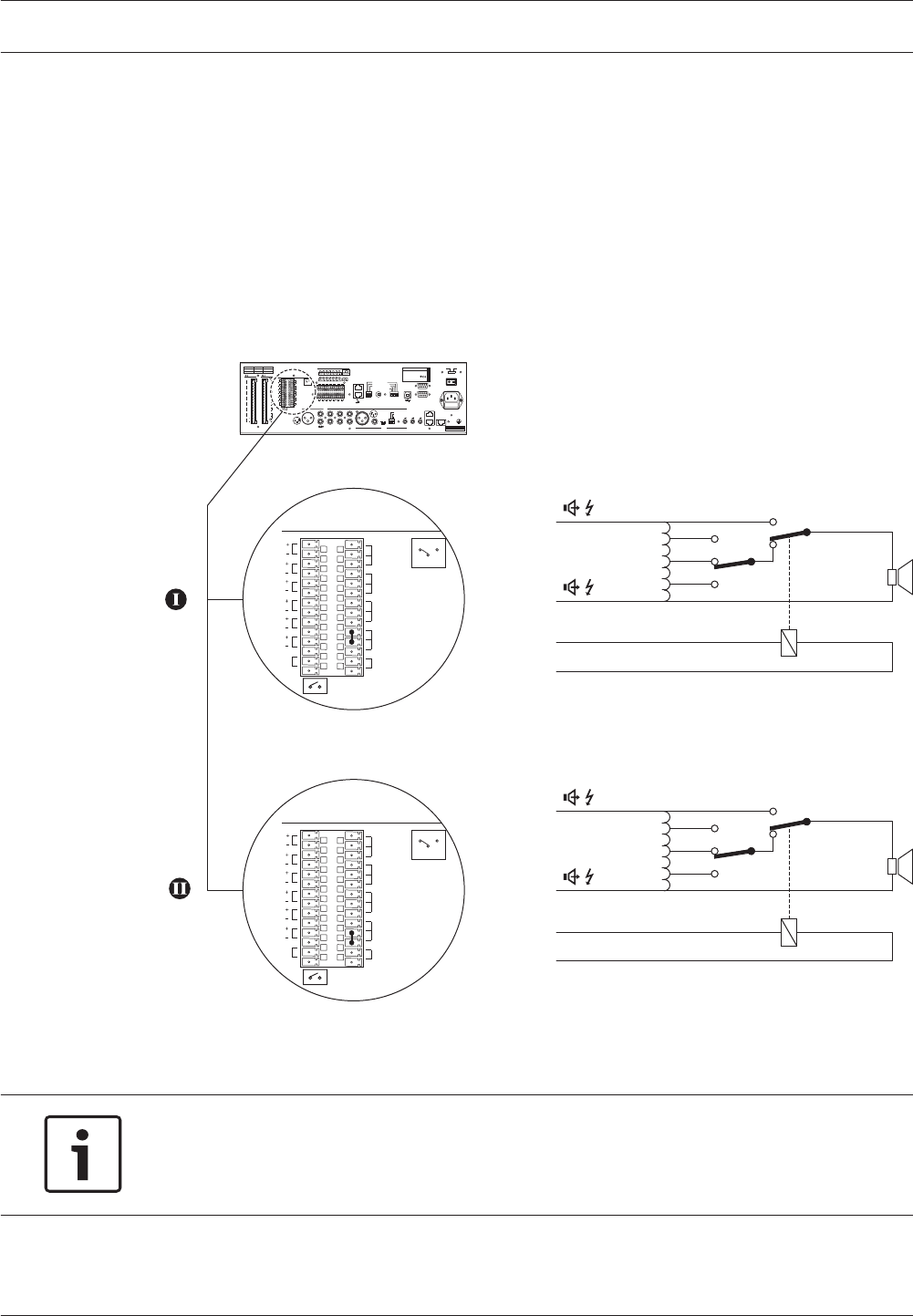
Normally, when there are no active calls, the Z+ pins are internally connected to the NC
contact of the Volume Override. At the moment a call is started in a zone, the Z+ pin of the
zone is internally connected to the NO contact of the Volume Override. So, the NC and the NO
contacts determine which voltage is supplied to the positive pins of the override outputs (Z+).
See situation I, for an example of a power-saving 4-wire volume override:
4Connect the NO contact of the Volume Override to the 24V contact of the Volume
Override.
See situation II, for an example of a fail-safe 4-wire volume override:
4Connect the NC contact of the Volume Override to the 24V contact of the Volume
Override.
CO M
NC N O
NC
TRG2
Override/Trigger Output
G 1
24V
EM
Fault
Call
Z1
Z2
Z3
Z4
Z5
Z6
NC
COM
NO
NC
COM
NO
NC
COM
NO
NO
24V
Volume Override
100V
0V
Z+
Z-
NO
NC
CO M
NC N O
NC
TRG2
Override/Trigger Output
G 1
24V
EM
Fault
Call
Z1
Z2
Z3
Z4
Z5
Z6
NC
COM
NO
NC
COM
NO
NC
COM
NO
NO
24V
Volume Override
100V
0V
Z+
Z-
NC
NO
Figure 5.9: 4‑wire volume override
To create a 3‑wire volume override:
Notice!
It is not possible to use 3‑wire volume override in combination with redundant loudspeaker
lines (line A and B, see figure 5.6) and supervision. If redundant loudspeaker lines are
needed, use 4‑wire volume override.
1. Connect the 100 V output of loudspeaker line A to the 100 V input of the volume control.
2. Connect the 100 V/0 V (CALL/RTN) of the transformer to the 100V output of loudspeaker
line B.
3. Connect the 0 output of loudspeaker line A to the 0 V of the loudspeaker.
Plena Connection | en 57
Bosch Security Systems B.V. Installation and Operation manual 2013.07 | V2.0 |
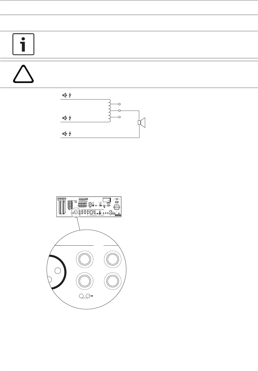
4. Enable 3‑wire volume override in the configuration software.
Notice!
See the Configuration Software Manual for more information about the configuration
software.
!
Caution!
Make sure that the correct connections have been made and the system is correctly
configured.
100V
A
A
B
100V
0V
Figure 5.10: 3‑wire volume override
Line output
The voice alarm controller has 1 line output. This output has a double cinch socket. Both cinch
sockets contain the same, mono signal, which consists of the current BGM and calls. The line
output can be used to connect the voice alarm controller to a recording device (e.g. a
tape‑deck).
In
ternal Booster CD/Tuner
Figure 5.11: Line output
5.1.8
58 en | Connection Plena
2013.07 | V2.0 | Installation and Operation manual Bosch Security Systems B.V.
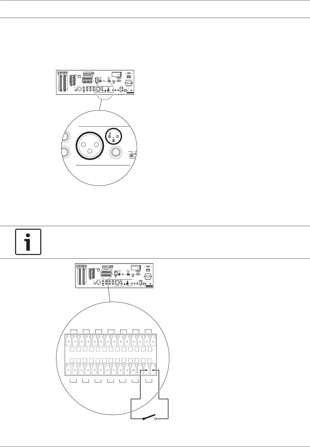
Mic/line input with VOX
The voice alarm controller has 1 mic/line input with voice-activated (VOX) functionality. This
input has 2 sockets; a balanced XLR socket and a balanced 6.3 mm jack socket. The signals
from both sockets are mixed to form a single input signal.
L
R
PC
Impedance
Calibration
Mic/Line
GND
Figure 5.12: Mic/line input with VOX functionality
The input automatically starts a business or emergency call if the input is higher than -10 dB
or if the VOX switch is closed. The input must be configured with the configuration software.
Notice!
See the Configuration Software Manual for more information about the configuration
software.
1 2 3 4 5 6
VOX Switch
1 2 3 4 5 6
24V
DC out
Figure 5.13: Connecting a VOX switch
5.1.9
Plena Connection | en 59
Bosch Security Systems B.V. Installation and Operation manual 2013.07 | V2.0 |
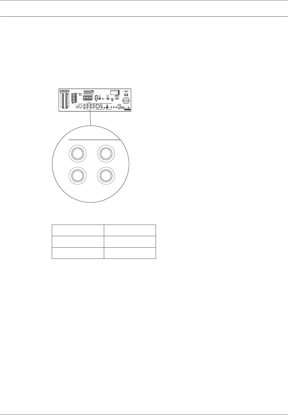
For example, the mic/line input with VOX functionality can be used to create a supervised link
to another emergency sound system (e.g. a Praesideo system).
BGM inputs
The voice alarm controller has 2 BGM inputs. Each BGM input has a double cinch socket. To
these cinch outputs, a background music source can be connected (e.g. a Bosch music
source). The signals connected to the L (left) and R (right) cinch sockets are mixed to form a
single input signal.
AUX
In
CD/Tuner
Figure 5.14: BGM inputs
Input Source
CD/Tuner CD or tuner
AUX Auxiliary source
Table 5.1: BGM inputs
5.1.10
60 en | Connection Plena
2013.07 | V2.0 | Installation and Operation manual Bosch Security Systems B.V.
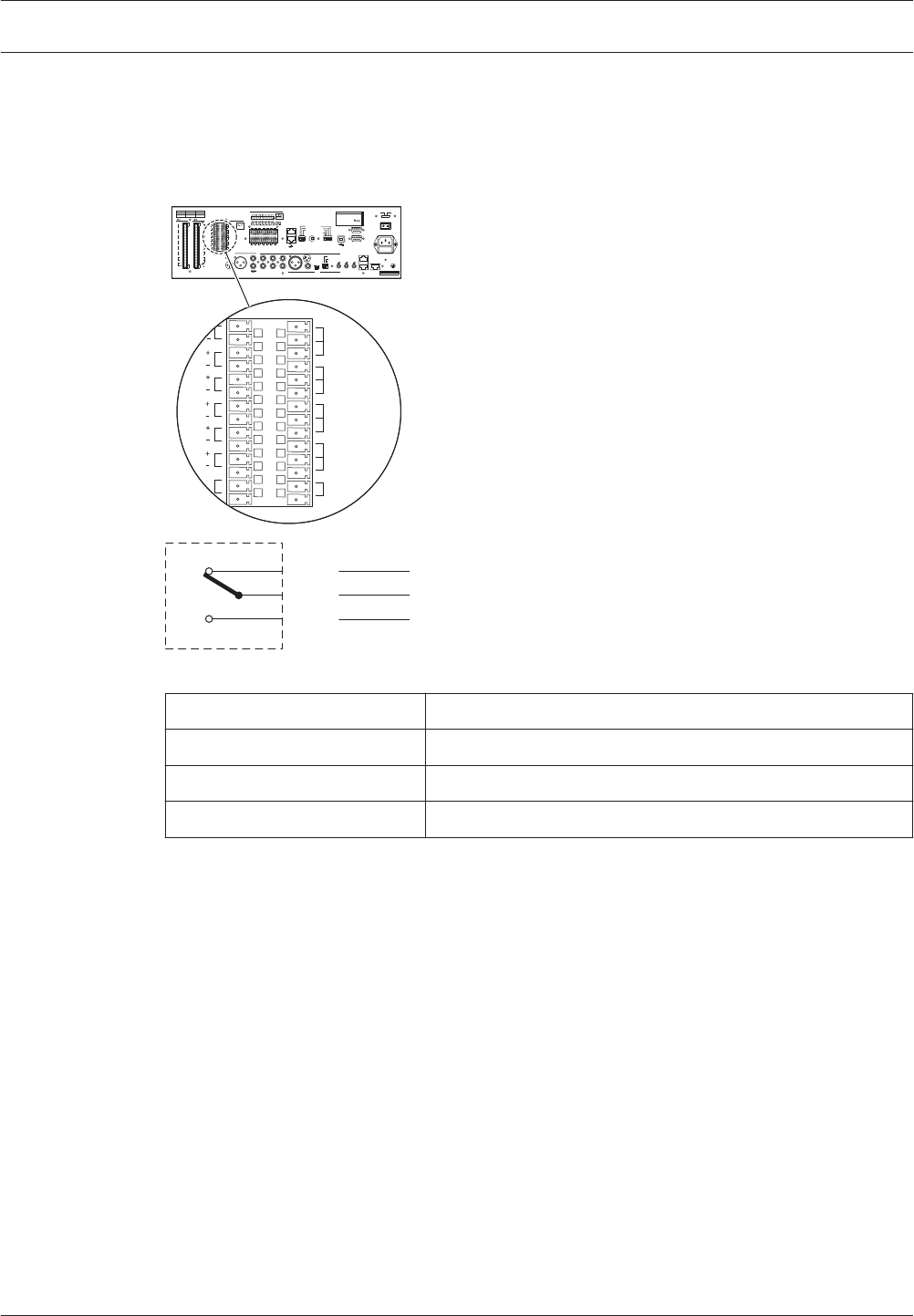
Status output contacts
The voice alarm controller has 3 status output contacts to indicate the current system state.
These are used to send the status of the Plena Voice Alarm Systemto third party equipment or
to connect sounders or similar indicating devices.
NC
TRG2
TR
24V
EMG
Fault
Call
Z1
Z2
Z3
Z4
Z5
Z6
NC
COM
NO
NC
COM
NO
NC
COM
NO
NO
V
NC
COM
NO
olume Override
Figure 5.15: Status output contacts (default)
Contact Description
EMG Emergency state (see section Emergency state, page 91).
Fault Fault state (see section Fault State, page 96).
Call Call active state.
Table 5.2: Status output contact
The status output contacts are internal relays. By default, NC is connected to COM. When the
Plena Voice Alarm System enters one of the states that are indicated, the relay connects NO to
COM.
5.1.11
Plena Connection | en 61
Bosch Security Systems B.V. Installation and Operation manual 2013.07 | V2.0 |
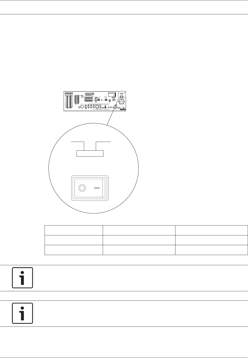
Power
Introduction
The voice alarm controller has the following power connections:
– Mains power connection.
– Back-up power connection.
Mains power
Proceed as follows to connect the voice alarm controller to the mains power:
4Select the local mains voltage using the voltage selector on the rear of the voice alarm
controller.
115V~ 230V~
Apparatus delivered
Connected for 230V~
Power
Figure 5.16: Voltage selector
Selector Mains voltage V(AC) Fuse
115 100 - 120 115 V - 10 AT
230 220 - 240 230 V - 6,3 AT
Table 5.3: Voltage selector
Notice!
The Voice Alarm Controller is delivered with the voltage selector in the 230 V position.
1. Put the correct type of fuse in the voice alarm controller.
Notice!
The Voice Alarm Controller is delivered with a T6.3L 250 V fuse for a mains voltage of
220 to 240 V(AC).
2. Connect a locally approved mains cord to the voice alarm controller.
3. Connect the mains cord to a locally approved mains outlet.
5.1.12
62 en | Connection Plena
2013.07 | V2.0 | Installation and Operation manual Bosch Security Systems B.V.
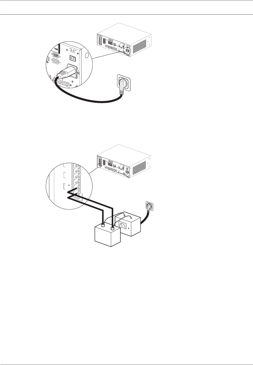
COM
NC NO
10k 10k
Trigger input/24V DC out
Business
Emergency
NC
TRG2
Override/Trigger Output
AUX
L
R
PC
Digital
Message
Monitoring
Speaker
Remote Control Panel
Impedance
Calibration
In
Voice AlarmController
Max. output power 360W
Ratedoutput power 240W
115-230V~, 50/60Hz
S/N.
Design & Quality
The Netherlands
N663
Phantom power
Z1
Z2
Z3
Z4
Z5
Z6
Ext
Booster
In
DC In
100V
0
TRG 1
Int
Booster
Out
24V
EMG
Fault
Call
External Booster
Out
CD/Tuner
SEL1
SEL0
Firmware
Upgrade
Monitor
APR mode
Supervision
2ch operation
LBB1994
Off
On
USB
Vox
Speech filter
Mic/Line
Vox
LBB1994
Rated input power:760VA
Line fuse
T6.3L250V for230V AC
T10L250V for115V AC
115V~ 230V~
Apparatus delivered
Connected for 230V~
Power
Router
Warning
This apparatus must be earthed
100V
0
100V
0
100V
0
100V
0
100V
0
100V
0
24V
70V
Z1
Z2
Z3
Z4
Z5
Z6
GND
Fireman's panel
1 2 3 4 5 6
1 2 3 4 5 6
1 2 3 4 5 6
Off
On
Off
On
Call station For service only
GND
24V
DC out
VOX
Switch
VOX Switch
1 2 3 4 5 6
NC
COM
NO
NC
COM
NO
NC
COM
NO
100V
0
Call out
100V
0
100V
0
100V
0
100V
0
100V
0
100V
0
Z2
Z3
Z4
Z5
Z6
Z1
A B
NO
24V
DC out
24V
1 Channel 2 Channel
Int Booster
Ext Booster
BGM/Spare
N.C./Spare
Call
BGM/Call
Volume Override
100V
1
2
1
2
Digital
Message
Monitoring
Speaker
Remote Control Panel
90/00 8900 199 00001
Plena Voice Alarm Controller
Max. output power 360W
Rated output power 240W
5-230V~, 50/60Hz
S/N.
Design & Quality
The Netherlands
N663
Phantom power
USB
LBB1994
Rated input power:760VA
Line fuse
T6.3L250V for230V AC
T10L250V for115V AC
115V~ 230V~
Apparatus delivered
Connected for 230V~
Power
Router
W
Fireman's panel
1
2
Figure 5.17: Connecting the mains cord
Back-up power
The voice alarm controller has a 24 V(DC) input to connect a back-up power supply (e.g. a
battery) which powers the system if the mains power is not available. See the connection
details below:
COM
NC NO
10k 10k
Trigger input/24V DC out
Business
Emergency
NC
TRG2
Override/Trigger Output
AUX
L
R
PC
Digital
Message
Monitoring
Speaker
Remote Control Panel
Impedance
Calibration
In
Voice AlarmController
Max. output power 360W
Ratedoutput power 240W
115-230V~, 50/60Hz
S/N.
Design & Quality
The Netherlands
N663
Phantom power
Z1
Z2
Z3
Z4
Z5
Z6
Ext
Booster
In
DC In
100V
0
TRG 1
Int
Booster
Out
24V
EMG
Fault
Call
External Booster
Out
CD/Tuner
SEL1
SEL0
Firmware
Upgrade
Monitor
APR mode
Supervision
2ch operation
LBB1994
Off
On
USB
Vox
Speech filter
Mic/Line
Vox
LBB1994
Rated input power:760VA
Line fuse
T6.3L250V for230V AC
T10L250V for115V AC
115V~ 230V~
Apparatus delivered
Connected for 230V~
Power
Router
Warning
This apparatus must be earthed
100V
0
100V
0
100V
0
100V
0
100V
0
100V
0
24V
70V
Z1
Z2
Z3
Z4
Z5
Z6
GND
Fireman's panel
1 2 3 4 5 6
1 2 3 4 5 6
1 2 3 4 5 6
Off
On
Off
On
Call station For service only
GND
24V
DC out
VOX
Switch
VOX Switch
1 2 3 4 5 6
NC
COM
NO
NC
COM
NO
NC
COM
NO
100V
0
Call out
100V
0
100V
0
100V
0
100V
0
100V
0
100V
0
Z2
Z3
Z4
Z5
Z6
Z1
A B
NO
24V
DC out
24V
1 Channel 2 Channel
Int Booster
Ext Booster
BGM/Spare
N.C./Spare
Call
BGM/Call
Volume Override
100V
1
2
1
2
Z6
Ext
In
DC In
100V
0
24V
100V
0
Charger
24 VDC
-+
Figure 5.18: Connecting a back-up power supply
Plena Connection | en 63
Bosch Security Systems B.V. Installation and Operation manual 2013.07 | V2.0 |
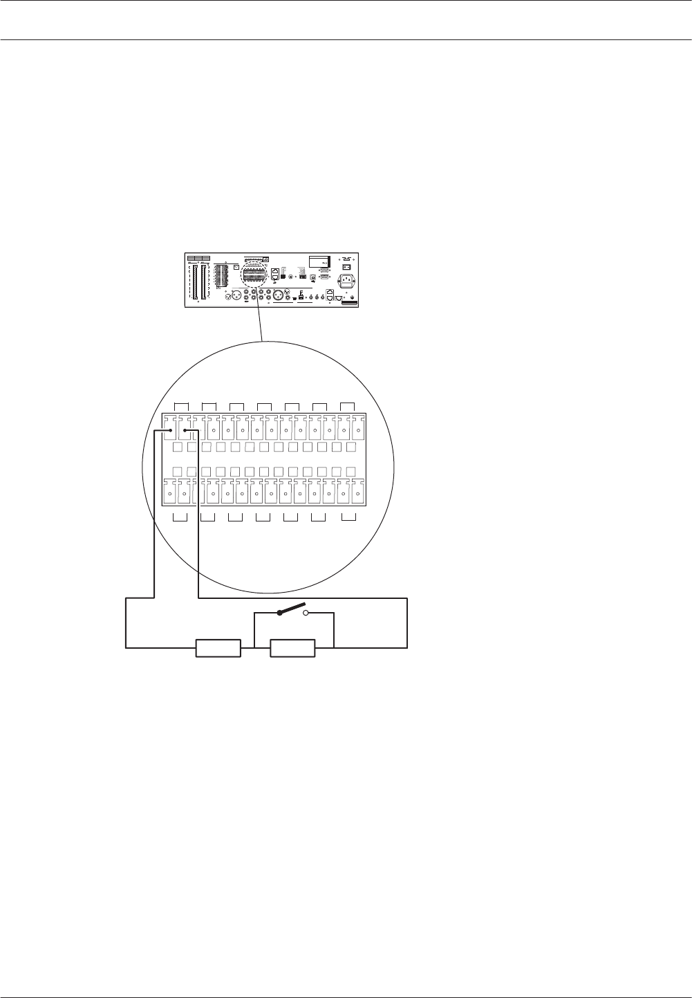
Trigger inputs
Introduction
The voice alarm controller has a terminal block to which 6 emergency (EMG) and 6 business
trigger inputs can be connected. Third party systems can use the trigger inputs to start
emergency and business calls in the Plena Voice Alarm System. The trigger inputs must be
configured with the configuration software.
Emergency trigger inputs
The upper part of the terminal block contains the emergency trigger inputs. The emergency
trigger inputs have a higher priority than the business trigger inputs.
1 2 3 4 5 6
VOX Switch
1 2 3 4 5 6
24V
DC out
10K 10K
Figure 5.19: Connecting emergency trigger inputs
5.1.13
64 en | Connection Plena
2013.07 | V2.0 | Installation and Operation manual Bosch Security Systems B.V.
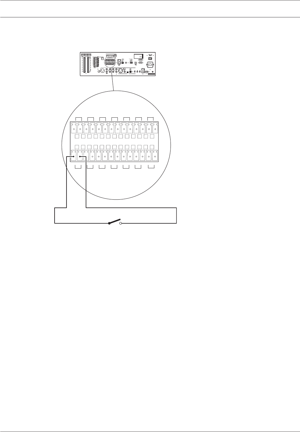
Business trigger inputs
The lower part of the terminal block contains the business trigger inputs. The business trigger
inputs have a lower priority than the emergency trigger inputs.
1 2 3 4 5 6
VOX Switch
1 2 3 4 5 6
24V
DC out
Figure 5.20: Connecting business trigger inputs
Plena Connection | en 65
Bosch Security Systems B.V. Installation and Operation manual 2013.07 | V2.0 |

Voice Alarm Router
Voice alarm controller
Connect the voice alarm router to the voice alarm controller (see section Voice alarm routers,
page 51).
Loudspeakers
The voice alarm router has 6 zone outputs (Z1 to Z6). The procedure for connecting
loudspeakers to a voice alarm router is the same as the procedure for connecting
loudspeakers to a voice alarm controller (see section Loudspeakers, page 54).
Volume overrides
The voice alarm router has 6 override outputs; 1 for each connected zone. These are suitable
for 4‑wire override (24 V) and for 3‑wire override. The procedure for using volume override in
zones that are connected to a voice alarm router is the same as the procedure for using
volume override in zones that are connected to the voice alarm controller (see section Volume
overrides, page 56).
Trigger inputs
The voice alarm router has a terminal block to which 6 emergency (EMG) and 6 business
trigger inputs can be connected. Third party systems can use the trigger inputs to start
emergency and business calls in the Plena Voice Alarm System. The trigger inputs must be
configured with the configuration software. The procedure for connecting trigger inputs to a
voice alarm router is similar to the procedure for connecting trigger inputs to the voice alarm
controller (see section Trigger inputs, page 64).
5.2
5.2.1
5.2.2
5.2.3
5.2.4
66 en | Connection Plena
2013.07 | V2.0 | Installation and Operation manual Bosch Security Systems B.V.
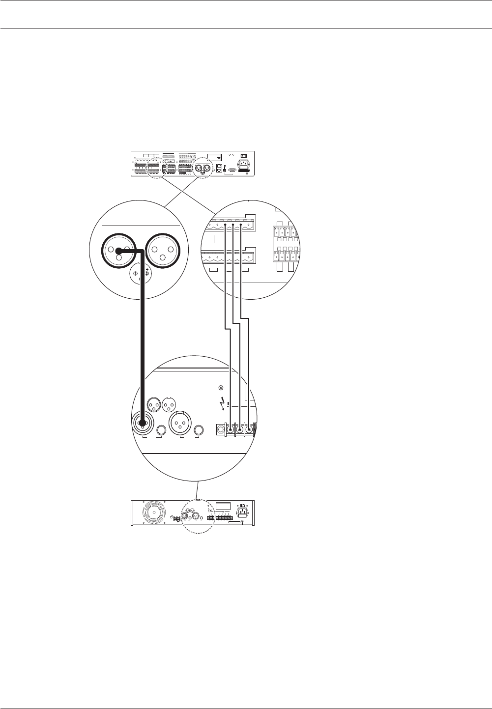
External power amplifiers
The voice alarm router has 2 external power amplifier outputs (line level, 1 V) and 1 external
power amplifier input (100 V) to connect two external power amplifiers. The function of the
external power amplifier (e.g. a Plena Power Amplifier) depends on the channel mode for
which the system is configured (see section 1-Channel mode operation, page 77 and section
2-Channel mode operation, page 78).
See the next information about connecting external power amplifier 1 to a voice alarm router:
Design & Quality
The Netherlands
Amplifier 1
Out
GND
Amplifier 2
100V 70V 0 0
line in line out
1 2
3
1 2
3
GND GND+ +
- -
0V 0 100V 0 100V 70V 0 100V
TRG1 TRG2
NC
B
Failure
0V 0 100V 0 100V 0 +24V-
Booster 2 in
Z5 Z6 DC In
Z1 Z2 Z3
Figure 5.21: Connecting external power amplifier 1
See the next information about connecting external power amplifier 2 to a voice alarm router:
5.2.5
Plena Connection | en 67
Bosch Security Systems B.V. Installation and Operation manual 2013.07 | V2.0 |
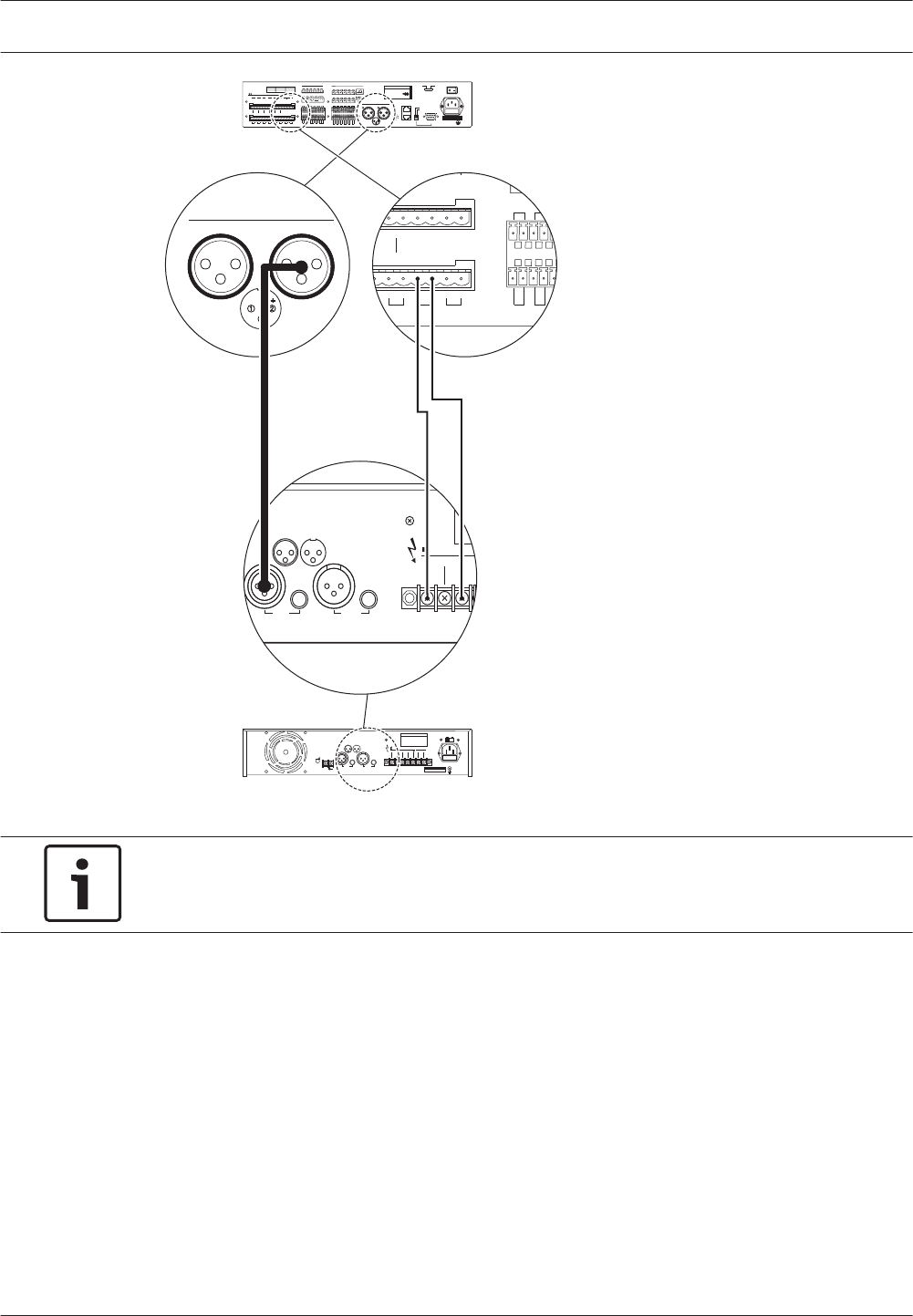
Design & Quality
The Netherlands
Out
GND
Amplifier 1 Amplifier 2
100V 70V 0 0
line in line out
1 2
3
1 2
3
GND GND+ +
- -
0V 0 100V 0 100V 70V 0 100V
TRG1 TRG2
NC
B
Failure
0V 0 100V 0 100V 0 +24V-
Booster 2 in
Z5 Z6 DC In
Z1 Z2 Z3
Figure 5.22: Connecting external power amplifier 2
Notice!
The internal power amplifier of the voice alarm controller can also be used as external power
amplifier for the voice alarm router.
Power
The procedure for connecting a voice alarm router to the mains power is the same as the
procedure for connecting the voice alarm controller to the mains (see section Power, page 62).
5.2.6
68 en | Connection Plena
2013.07 | V2.0 | Installation and Operation manual Bosch Security Systems B.V.
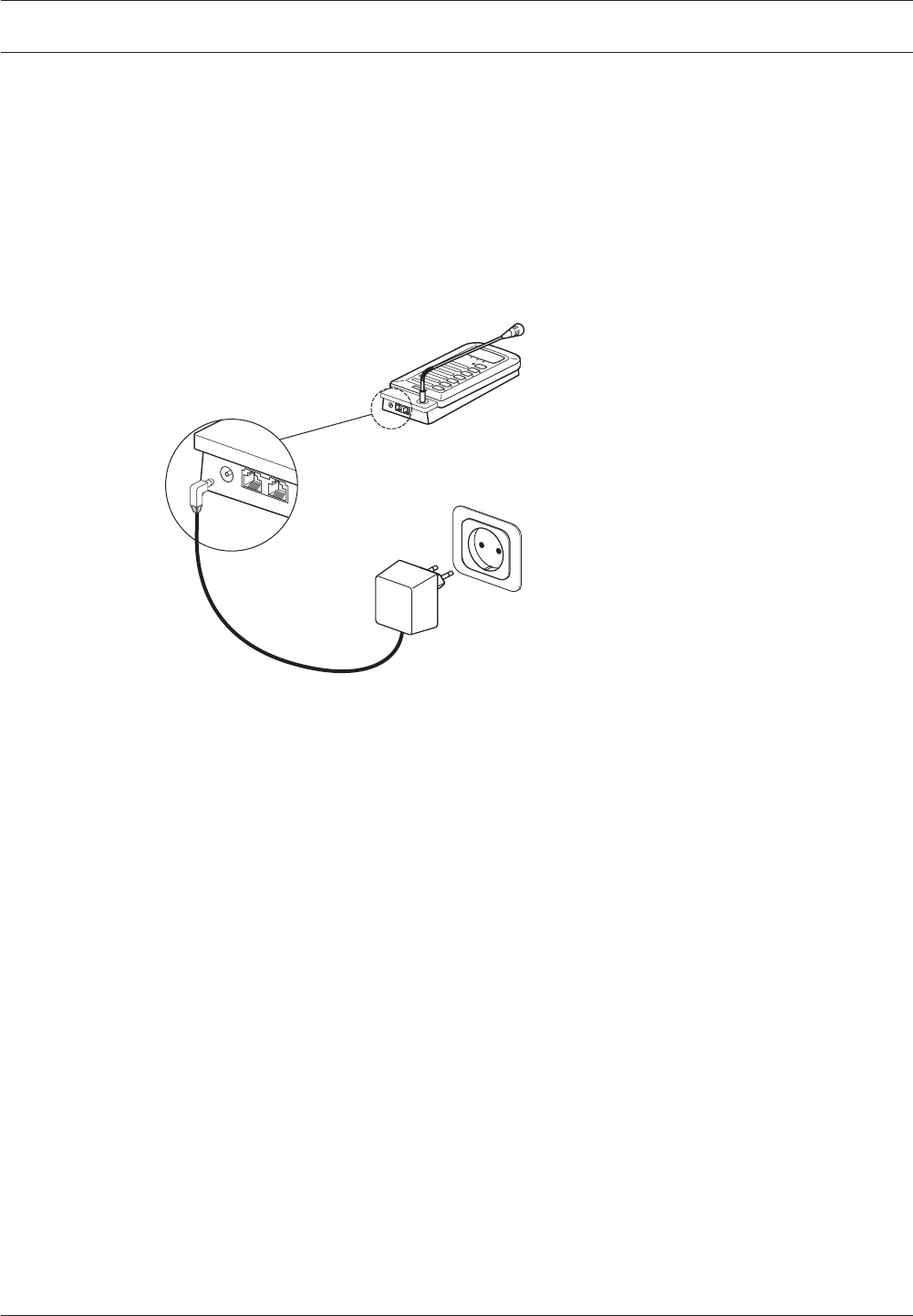
Call Station
Voice alarm controller
Connect the call station to the voice alarm controller (see section Call station, page 50).
Power supply
If the cable between the voice alarm controller or the previous call station is longer than
100 m, the call station may sometimes need to be connected to a 24 V(DC) power source. See
the connection details below:
Figure 5.23: Connecting a power supply
Keypads
The maximum number of keypads that can be connected to a call station is 8 (see section Call
Station Keypad, page 44).
5.3
5.3.1
5.3.2
5.3.3
Plena Connection | en 69
Bosch Security Systems B.V. Installation and Operation manual 2013.07 | V2.0 |
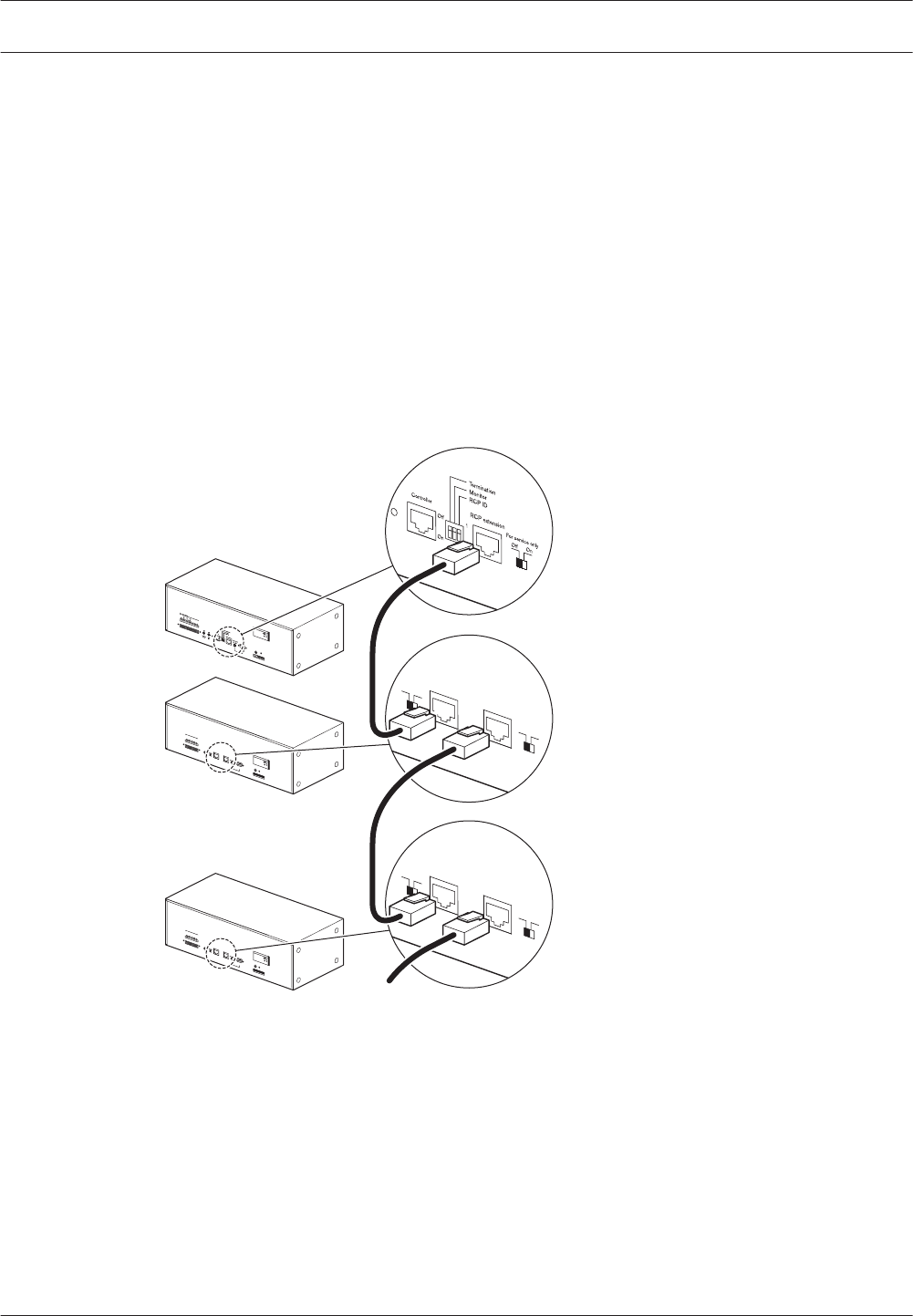
Voice Alarm Remote Control
Voice alarm controller
Connect the remote control panel to the voice alarm controller (see section Remote controls,
page 53).
Remote control extensions
The remote controller has 1 socket for remote control extensions (Remote Control Extension,
Remote Control Extension kit). Use shielded CAT‑5 Ethernet cables with RJ45 plugs to
connect a remote control extension to the remote control. When the system requires more
than 1 remote control extension, use the system sockets on the remote control extension to
make loop‑throughs. See the connection details below.
The termination switch must be set to ON. If not, over long distances, the data bus can
malfunction.
RCP ext. In RCP ext. Out
Off On
T
ermination For service only
Off On
RCP ext. In RCP ext. Out
Off On
T
ermination For service only
Off On
6
1...9
ID
1
2
3
4
5
7
9
8
RCP ext. In RCP ext. Out
Off On
T
ermination
Firmware
Upgrade
For service only
Off On
Warning
This apparatus must be earthed
Trigger Output
Power
24V
DC In 3
21
Fault
Design & Quality
The Netherlands
RC Panel Extension
Max. input power
200mA, 24V DC
S/N.
A035413
N663
NC
NO
COM
Design & Quality
The Netherlands
RC Panel
Max. input power
300mA, 24V DC
S/N.
PLN-V6RC
A035413
N663
Figure 5.24: Connecting remote control extensions
Status output contacts
The remote control panel has 3 status output contacts to indicate the current system state.
The procedure for connecting the status outputs is the same as the procedure for connecting
status outputs to the voice alarm controller (see section Status output contacts, page 61).
5.4
5.4.1
5.4.2
5.4.3
70 en | Connection Plena
2013.07 | V2.0 | Installation and Operation manual Bosch Security Systems B.V.
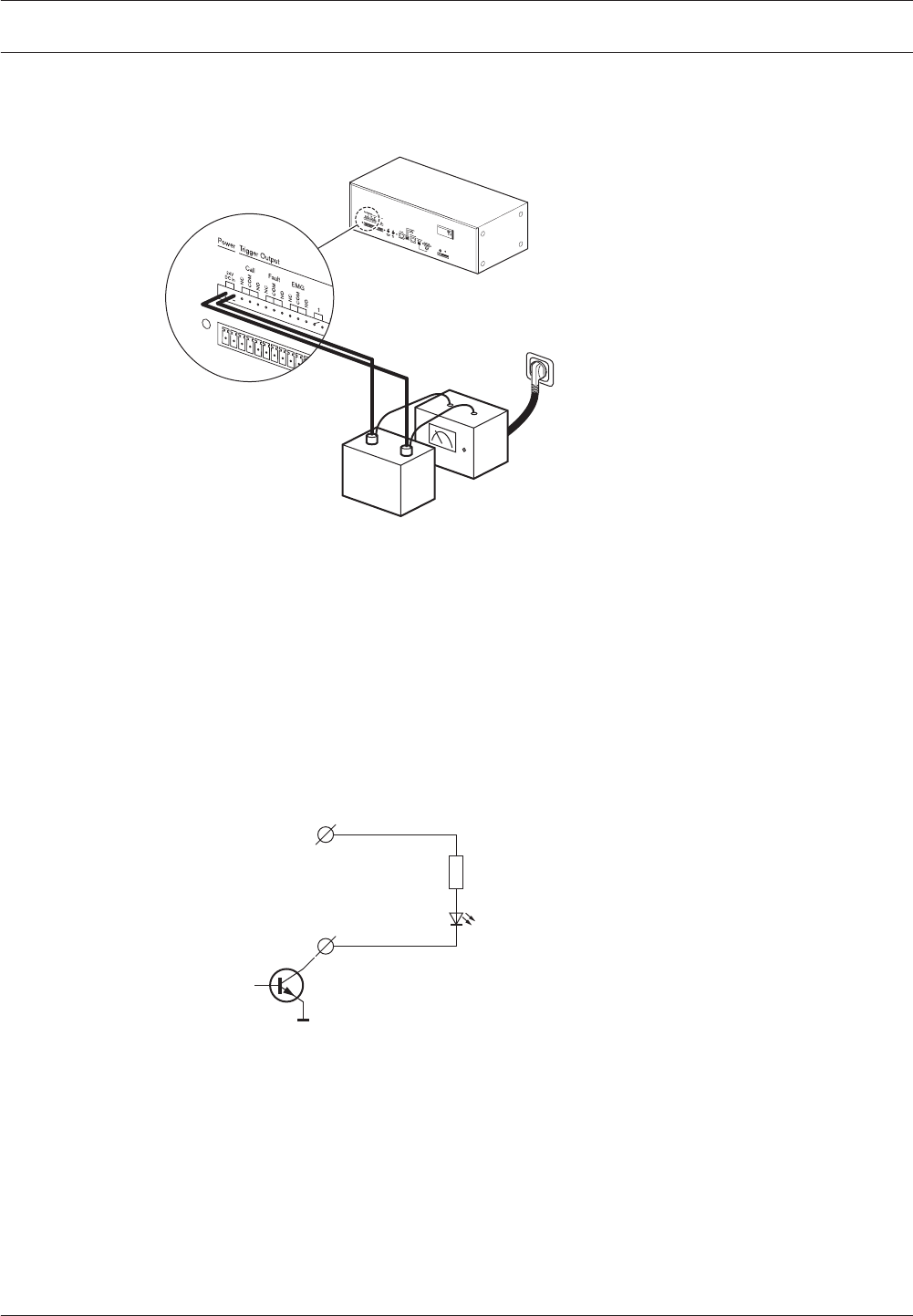
Power
Connect a power supply to the remote control panel:
Design & Quality
The Netherlands
RC Panel
Max
. input power
300mA
, 24V DC
S/N.
A035413
N663
Charger
24 VDC
-+
Figure 5.25: Connecting a 24 VDC power supply
Voice Alarm Remote Control Kit
Rear panel
The rear panel of the remote control kit has the same connectors and controls as the rear
panel of the Voice Alarm Remote Control. See section Voice Alarm Remote Control, page 70 for
connection details.
LEDs
To the LEDS/LAMPS connectors on the front panel of the remote control kit, the LEDs can be
connected.
24 V output
5 k
LEDS/LAMPS
connector
W
Figure 5.26: Connecting LEDs
5.4.4
5.5
5.5.1
5.5.2
Plena Connection | en 71
Bosch Security Systems B.V. Installation and Operation manual 2013.07 | V2.0 |
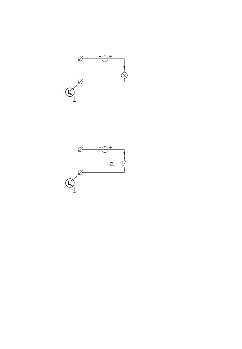
Lamps
To the LEDS/LAMPS connectors on the front panel of the remote control kit, lamps can be
connected:
GND
max. 52 V
LEDS/LAMPS
connector
< 200 mA
Figure 5.27: Connecting lamps
Relays
To the LEDS/LAMPS connectors on the front panel of the remote control kit, relays can be
connected:
GND
max. 52 V
LEDS/LAMPS
connector
< 100 mA
Figure 5.28: Connecting relays
5.5.3
5.5.4
72 en | Connection Plena
2013.07 | V2.0 | Installation and Operation manual Bosch Security Systems B.V.
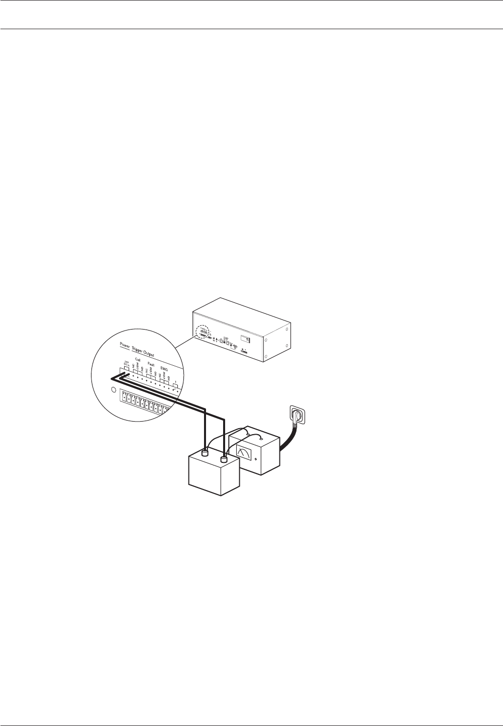
Remote Control Extension
Remote control
Connect the remote control extension to the remote control (see section Remote control
extensions, page 70).
Status output contacts
The remote control extension has 3 status output contacts to indicate the current system
state. The procedure for connecting the status outputs is the same as the procedure for
connecting status outputs to the voice alarm controller (see section Status output contacts,
page 61).
Power
Connect a back‑up power supply to the remote control extension.
The 24 V output of the Controller or the Router can be used for this. Those outputs are
powered by mains and back‑up power. It is also possible to install a floating (without ground
reference) 24 V power supply with backup battery (EN54‑4 compliant for EN54‑16 compliant
systems, or EN60849 compliant).
Design & Quality
The Netherlands
RC Panel
Max
. input power
300mA
, 24V DC
S/N.
A035413
N663
Charger
24 VDC
-+
Figure 5.29: Connecting a power supply
Remote Control Extension Kit
Rear panel
The rear panel of the remote control extension kit has the same connectors and controls as
the rear panel of the Voice Alarm Control Extension. See section Remote Control Extension,
page 73 for connection details.
LEDs
To the LEDs/LAMPS connectors on the front panel of the remote control extension kit, the
LEDs can be connected (see Voice Alarm Remote Control kit, page 27).
Lamps
To the LEDs/LAMPS connectors on the front panel of the remote control extension kit, lamps
can be connected (see Voice Alarm Remote Control kit, page 27).
5.6
5.6.1
5.6.2
5.6.3
5.7
5.7.1
5.7.2
5.7.3
Plena Connection | en 73
Bosch Security Systems B.V. Installation and Operation manual 2013.07 | V2.0 |

Relays
To the LEDs/LAMPS connectors on the front panel of the remote control extension kit, relays
can be connected (see Voice Alarm Remote Control kit, page 27).
Fireman’s Panel
Voice alarm controller
Connect the fireman’s panel to the voice alarm controller (see section Remote controls, page
53).
Remote control extensions
The fireman’s panel has 1 socket for remote control extensions (Remote Control Extension,
Remote Control Extension kit). Use shielded CAT‑5 Ethernet cables with RJ45 plugs to
connect a remote control extension to the fireman’s panel. When the system requires more
than 1 remote control extension, use the system sockets on the remote control extension to
make loop‑throughs. See section Remote control extensions, page 70 for connection details.
Status output contacts
The fireman’s panel has 3 status output contacts to indicate the current system state. The
procedure for connecting the status outputs is the same as the procedure for connecting
status outputs to the voice alarm controller (see section Status output contacts, page 61).
Power
The procedure for connecting a fireman’s panel to a power supply is the same as the
procedure for connecting a remote control to a power supply (see section Power, page 71).
5.7.4
5.8
5.8.1
5.8.2
5.8.3
5.8.4
74 en | Connection Plena
2013.07 | V2.0 | Installation and Operation manual Bosch Security Systems B.V.

Configuration
A number of functions of the Plena Voice Alarm System is hardware configured using, for
example, DIP switches and volume controls. Other parts of the system must be software
configured using the Plena Voice Alarm System configuration software. A description of this
software is beyond the scope of this manual. This manual only describe the hardware
configuration of a Plena Voice Alarm System.
Notice!
See the Configuration Software Manual for more information about the configuration
software.
It is recommended to do the hardware configuration of the system before the software
configuration.
System settings
The system settings are configured using DIP switches on the rear of the voice alarm
controller. By default, all switches are in the OFF position.
1
2
3
4
5
Off
On
Figure 6.1: System settings DIP switches
No DIP switch Description
1 Monitor Switches the monitoring loudspeaker on (ON) and off (OFF). See
section Monitor, page 76.
2APR mode Switches the Asian Pacific Region mode on (ON) and off (OFF). See
section APR mode, page 76.
3Supervision Switches supervision on (ON) and off (OFF). See section Supervision,
page 76.
42ch operation Switches2-channel operation on (ON) and off (OFF). See section 1-
Channel mode operation, page 77 and section 2-Channel mode
operation, page 78.
5Reserved Reserved. This DIP switch must always be in the OFF position.
Table 6.1: System settings DIP switches
6
6.1
Plena Configuration | en 75
Bosch Security Systems B.V. Installation and Operation manual 2013.07 | V2.0 |

Monitor
If the Monitor switch is in the ON position, the internal monitoring loudspeaker of the voice
alarm controller is switched on. The volume of the monitoring loudspeaker is set with the
Monitoring Speaker volume control (see Controls, connectors and indicators, page 14, no. 36).
APR mode
If the APR mode switch is in the ON position, the system is in the Asian-Pacific Region (APR)
mode. In APR mode, the system operates according to the emergency standards of the Asian-
Pacific Region. In the APR mode:
– The priority level of the emergency trigger inputs is always 14.
– Emergency and business trigger inputs of the same zone form pairs. The settings of the
emergency trigger input (software configurable) apply to both.
– The emergency trigger inputs are never supervised.
– When an emergency trigger input is activated, the system enters the emergency state.
The voice alarm controller also automatically starts a pre-emergency announcement and
alarm message (software configurable).
– When a business trigger input is activated, the system enters the emergency state. The
voice alarm controller does not automatically start a pre‑emergency announcement and
alarm message.
– The red LED, which during normal operation indicates that the zone is selected for an
emergency call (see Controls, connectors and indicators, page 14, no. 5), indicates that an
emergency trigger input is active.
– The green LED, which during normal operation indicates that a business call is running in
the zone (see Controls, connectors and indicators, page 14, no. 5), indicates that an
emergency call is running in the zone.
– The priority level of the emergency microphone of the voice alarm controller is always 16.
– When the emergency button (see Controls, connectors and indicators, page 14, no. 12) is
pushed on the front of the voice alarm controller, an alarm message is automatically
started. This message is automatically repeated.
Supervision
If the Supervision switch (see System settings, page 75) is in the ON position, supervision is
enabled. If it is in the OFF position, supervision is disabled. See section Supervision, page 78
for more information about supervision.
6.1.1
6.1.2
6.1.3
76 en | Configuration Plena
2013.07 | V2.0 | Installation and Operation manual Bosch Security Systems B.V.

1-Channel mode operation
If the 2ch operation switch (see 2-Channel mode operation, page 78) is in the OFF position,
the system operates in the 1‑channel mode.
Voice alarm controller
In the 1‑channel mode, all calls and BGM are amplified by the internal power amplifier of the
voice alarm controller. If desired, an external power amplifier can be connected for spare
switching (see section External power amplifier, page 52). In 1‑channel mode, all calls will
interrupt the BGM.
Amplifier Function
Internal BGM/Call power amplifier.
External Not connected/Spare power amplifier.
Table 6.2: 1-channel mode, voice alarm controller
Voice alarm router
One or two external power amplifiers can be connected to a voice alarm router to increase the
power of the system (see section External power amplifiers, page 67). In 1‑channel mode:
– External power amplifier 1 of the voice alarm router is used to increase the power for
calls and BGM, that go via the internal power amplifier of the voice alarm controller.
– External power amplifier 2 of the voice alarm router is used for spare-switching.
Amplifier Function
1 BGM/Call power amplifier.
2 Not connected/Spare power amplifier.
Table 6.3: 1-channel mode, voice alarm router
6.1.4
Plena Configuration | en 77
Bosch Security Systems B.V. Installation and Operation manual 2013.07 | V2.0 |
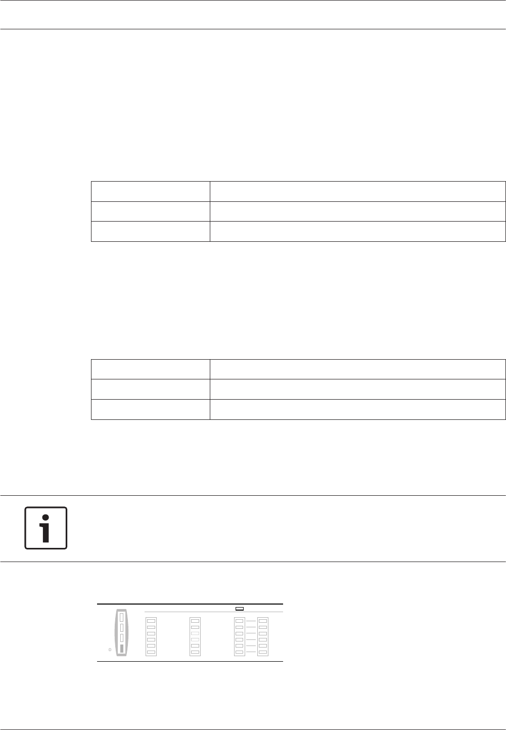
2-Channel mode operation
If the 2ch operation switch (see System settings, page 75) is in the ON position, the system
operates in the 2‑channel mode.
Voice alarm controller
In the 2‑channel mode, the BGM is amplified by the internal power amplifier of the voice alarm
controller. The calls are amplified by the external power amplifier, which is connected to the
voice alarm controller (see section External power amplifier, page 52). If the external power
amplifier is faulty, the calls are amplified by the internal power amplifier. In 2‑channel mode,
calls do not interrupt the BGM.
Amplifier Function
Internal BGM/Spare power amplifier.
External Call power amplifier.
Table 6.4: 2-channel mode, controller
Voice alarm router
One or two external power amplifiers can be connected to a voice alarm router to increase the
power of the system (see section External power amplifiers, page 67). In 2‑channel mode:
– External power amplifier 1 of the voice alarm router is used to increase the power of the
internal power amplifier of the voice alarm controller.
– External power amplifier 2 of the voice alarm router is used to help the external power
amplifier of the voice alarm controller to amplify calls.
Amplifier Function
1 BGM/Spare power amplifier.
2 Call power amplifier.
Table 6.5: 2-channel mode, router
Supervision
If the Supervision switch (see System settings, page 75) is in the ON position, supervision is
enabled. If it is in the OFF position, supervision is disabled.
Notice!
Supervision is only necessary for systems that have to comply to the IEC60849 evacuation
standard. If the system does not have to comply to this standard, leave the switch in the OFF
position.
If the Supervision switch is in the OFF position, the Disabled indicator on the front panel of
the voice alarm controller is lit to indicate that supervision is switched off.
Processor reset
Network
Call/EMG
Music/Spare
Ground short
Input
Mains
Battery
Zone1
Zone2
Zone3
Zone4
Zone5
Zone6
Fault Indicators
AB
Disabled
Message
EMG mic
RCP
Router
0 dB
-6dB
-20dB
Figure 6.2: Disabled indicator
If the Supervision switch is in the ON position, an indicator is lit when a supervised function
fails (see section Fault State, page 96). Use the configuration software to switch supervised
functions on and off.
6.1.5
6.2
78 en | Configuration Plena
2013.07 | V2.0 | Installation and Operation manual Bosch Security Systems B.V.

Notice!
See the Configuration Software Manual for more information about the configuration
software.
Processor reset
Watchdog
If supervision is enabled (see section Supervision, page 78), the processor of the voice alarm
controller is supervised by a watchdog. If the watchdog triggers, the Processor reset indicator
on the front panel of the voice alarm controller is lit. Then, the program memory is checked
and the processor resumes operation within 10 seconds. The indicator remains on until the
fault is acknowledged and reset.
New firmware
A processor reset sometimes happens after new firmware is installed. make sure the Service
DIP switches are put back to the correct position. The correct positions are:
– SEL0 and SEL1 to ON.
– Enable Firmware Download to OFF.
Network
If supervision is enabled and network supervision is switched on (see section Supervision,
page 78), the connections from the voice alarm controller to the voice alarm routers and
remote controls are supervised. When any voice alarm router or remote control is missing
during a network check, a network error is reported.
Power amplifiers
If supervision is enabled and call power amplifier supervision is switched on (see section
Supervision, page 78), the call power amplifiers in the system are supervised. In the
configuration software, mark the checkbox Call/EMG to enable this function.
If supervision is enabled and BGM/Spare power amplifier supervision is switched on (see
section Supervision, page 78), the BGM and spare power amplifiers in the system are
supervised. In the configuration software, mark the checkbox Spare to enable this function.
Ground short
If supervision is enabled and ground short supervision is switched on (see section Supervision,
page 78), the system can continuously monitor loudspeaker lines in the system for short-to-
ground situations. For each loudspeaker line, short-to-ground supervision can be switched on
and off with the configuration software.
Notice!
See the Configuration Software Manual for more information about the configuration
software.
If a leakage current > 30 + 15 mA is detected in a line, the line is considered faulty.
6.2.1
6.2.2
6.2.3
6.2.4
Plena Configuration | en 79
Bosch Security Systems B.V. Installation and Operation manual 2013.07 | V2.0 |
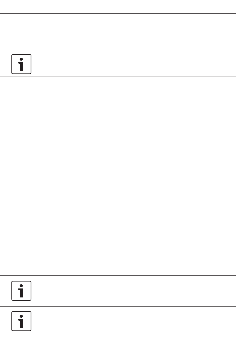
Emergency trigger inputs
If supervision is enabled and input supervision is switched on (see section Supervision, page
78), the system can supervise the emergency trigger inputs. For each emergency trigger input,
supervision can be switched on and off with the configuration software.
Notice!
See the Configuration Software Manual for more information about the configuration
software.
Mains power
If supervision is enabled and mains power supervision is switched on (see section Supervision,
page 78), the availability of the mains power is supervised.
Battery
If supervision is enabled and battery supervision is switched on (see section Supervision, page
78), the availability of the back-up power is supervised.
Message supervision
If supervision is enabled and message supervision is switched on (see section Supervision,
page 78), the internal message manager of the voice alarm controller is supervised. This
message supervision consists of supervision of the wave player using a check‑sum and
supervision of the audio path using a pilot‑tone.
Emergency microphone
If supervision is enabled and emergency microphone supervision is switched on (see section
Supervision, page 78), the audio path and the PTT switch of the emergency microphone are
monitored from the capsule to the connection with the voice alarm controller.
Line supervision
If supervision is enabled and line supervision (see section Supervision, page 78) is switched
on, all loudspeaker lines are supervised. Line supervision consists of:
– Impedance supervision.
– Short‑to‑ground supervision.
Impedance supervision
If line supervision is switched on, the voice alarm controller measures the impedance of all
loudspeaker lines once every 90 seconds (default value). The reference values for impedance
supervision are stored in the voice alarm controller during the system calibration (see section
Calibration, page 87). If a difference of > 15% (default value) is detected between the
measured line impedance and its reference value, the line is considered faulty. The default
values can be changed with the configuration software.
Notice!
A small click can be heard at the start and end of an impedance measurement. If the click is
unacceptable, then end of line supervision with EOL can be considered instead of impedance
supervision.
Notice!
See the Configuration Software Manual for more information about the configuration
software.
6.2.5
6.2.6
6.2.7
6.2.8
6.2.9
6.2.10
80 en | Configuration Plena
2013.07 | V2.0 | Installation and Operation manual Bosch Security Systems B.V.
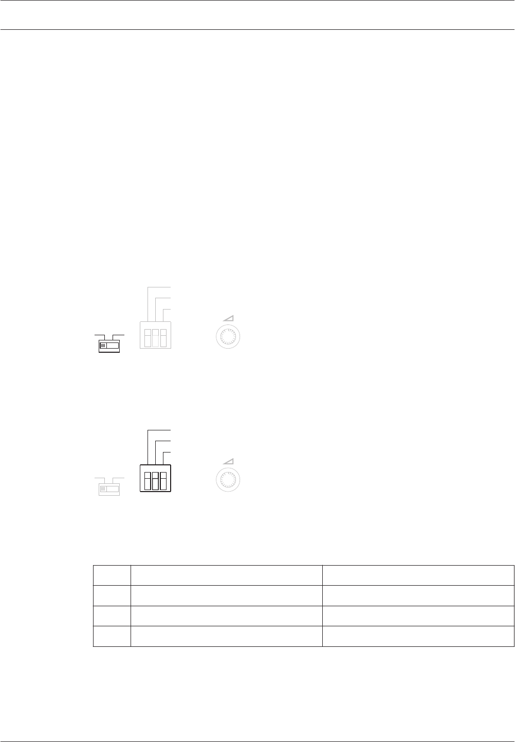
Short-circuit supervision
If line supervision is switched on, the voice alarm controller continuously monitors all
loudspeaker lines in the system for short-circuits.
If a short‑circuit is detected, the line output of the short-circuited line is isolated and shut
down within 200 ms. The system will remain operational. If the line is dual-redundant
connected (A and B), the short-circuited line remains operational as well.
When a ground short occurs, first check the 0 V and 100 V connections from the amplifier to
the Voice Alarm Controller. If these connections are incorrect, then a short fault can occur at
unpredictable times.
Voice alarm controller
VOX configuration
The type of source that is connected to the mic/line input with VOX functionality is set using
the Mic/Line switch on the rear of the voice alarm controller.
– If the source is a microphone, put the switch in the Mic. position.
– If the source is a line-level source, put the switch in the Line position.
Phantom power
Vox
Speech filter
Off
On
Mic/Line
Figure 6.3: VOX input source switch
The mic/line input with VOX functionality is configured using DIP switches on the rear of the
voice alarm controller. By default, all switches are in the OFF position.
Phantom power
Vox
Speech filter
Off
On
Mic/Line
Figure 6.4: VOX settings
The settings that can be made using the DIP switches are explained in a table on the rear of
the voice alarm controller (see the following table).
Off On
1 VOX activated by mic. VOX activated by VOX switch.
2 Speech filter. Flat.
3 Phantom power Off. Phantom power On.
Table 6.6: Vox settings
The volume of the mic/line input with VOX functionality is set with the VOX volume control.
6.3
6.3.1
Plena Configuration | en 81
Bosch Security Systems B.V. Installation and Operation manual 2013.07 | V2.0 |
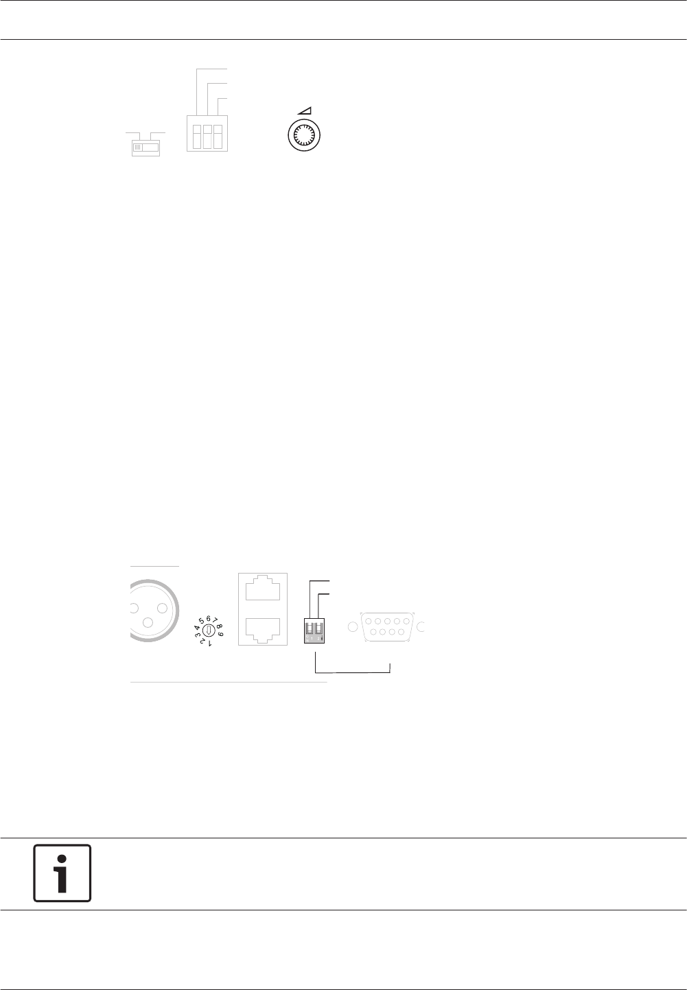
Phantom power
Vox
Speech filter
Off
On
Mic/Line
Figure 6.5: VOX volume control
VOX
If the VOX switch is in the OFF position, the input is activated when the voltage of the signal
of the source is above the specified threshold. If the VOX switch is in the ON position, the
input is activated when the VOX Switch trigger input is closed (see also section Mic/line input
with VOX, page 59).
Speech filter
If the Speech filter switch is in the OFF position, a speech filter is activated for the mic./line
input with VOX functionality. The speech filter improves the speech intelligibility by cutting off
the lower frequencies.
Phantom power
If the Phantom power switch is in the ON position, a phantom power supply is activated. This
switch only has to be put in the ON position if the source is a microphone that must receive
phantom power. If the source is not a microphone or if the microphone does not accept
phantom power, leave the switch in the OFF position.
Voice alarm router
The voice alarm routers are configured using an ID selector and a DIP switch:
Booster 1
Out
1...9
ID
Router
GND
Booster 2
In
Out
Firmware upgrade
Firmware Upgrade
Termination
Off
On
Figure 6.6: Router settings
Router ID
The ID of the voice alarm router is set using an ID selector (17). Each voice alarm router must
have a unique ID (1 to 19). Use a small screwdriver to turn the arrow in the correct position.
The DIP switch (15) has 3 switches. The first switch (left) determines whether the router has
address 0x (1 to 9) or 1x (10 to 19).
Notice!
The switch “Firmware upgrade” must be set to “ON” to execute the firmware upgrade. When
the upgrade is complete, the switch must be set back to “OFF”.
Termination switch
The last voice alarm router in a sequence of looped-through routers must always be
terminated. Only for these voice alarm routers, put the Termination switch in the ON position.
6.3.2
6.3.3
6.3.4
6.3.5
6.3.6
6.3.7
82 en | Configuration Plena
2013.07 | V2.0 | Installation and Operation manual Bosch Security Systems B.V.

Call station
The call stations are configured using the DIP switch at the bottom:
ON
1 2 3 4 5 6 7 8
Figure 6.7: Call station DIP switches
DIP switch Description
1, 2, 3, 4 Set the ID of the call station. See section Call station ID, page 83.
5, 6 Set the sensitivity of the call station. See section Sensitivity, page 83.
7Switches the speech filter on (ON) and off (OFF). See section Speech filter,
page 84.
8Switches termination on (ON) and off (OFF). See section Termination, page
84.
Table 6.7: Call station DIP switches
Call station ID
The ID of the call station is set using switches 1 to 4. Each call station must have a unique ID
(1 to 9).
Sensitivity
The sensitivity of the call station is set using switches 5 and 6:
Sensitivity Switch 5 Switch 6
-15 dB OFF OFF
0 dB OFF ON
6 dB ON OFF
Reserved ON ON
Table 6.8: Call station sensitivity
6.4
6.4.1
6.4.2
Plena Configuration | en 83
Bosch Security Systems B.V. Installation and Operation manual 2013.07 | V2.0 |

Speech filter
If switch 7 is in the ON position, a speech filter is activated for the call station. The speech
filter improves the speech intelligibility by cutting off the lower frequencies.
Termination
The last call station in a sequence of looped-through call stations must always be terminated.
Only for these call stations, put switch 8 in the ON position.
Notice!
The Controller comes with a termination plug (RJ45). Plug this connector in the unused RJ45
socket.
6.4.3
6.4.4
84 en | Configuration Plena
2013.07 | V2.0 | Installation and Operation manual Bosch Security Systems B.V.

Remote control
The remote controls are configured using a DIP switch:
Figure 6.8: Remote control settings
Remote control ID
The ID of the remote control is set using the Remote Control Panel ID switch. The ID of the
remote control must be the same as the number of the RCP connection of the voice alarm
controller to which the remote control is connected (1 to 2). Actions that are started by the
remote control with ID 1 have a higher priority than actions that are started by the remote
control with ID 2.
Monitor
If the Monitor switch is in the ON position, the internal monitoring loudspeaker of the remote
control is switched on. The volume of the monitoring loudspeaker is set with the Monitoring
Speaker volume control on the rear panel of the remote control.
Termination switch
If there are no remote control extensions connected to the remote control, the termination
switch must be in the ON position.
6.5
6.5.1
6.5.2
6.5.3
Plena Configuration | en 85
Bosch Security Systems B.V. Installation and Operation manual 2013.07 | V2.0 |
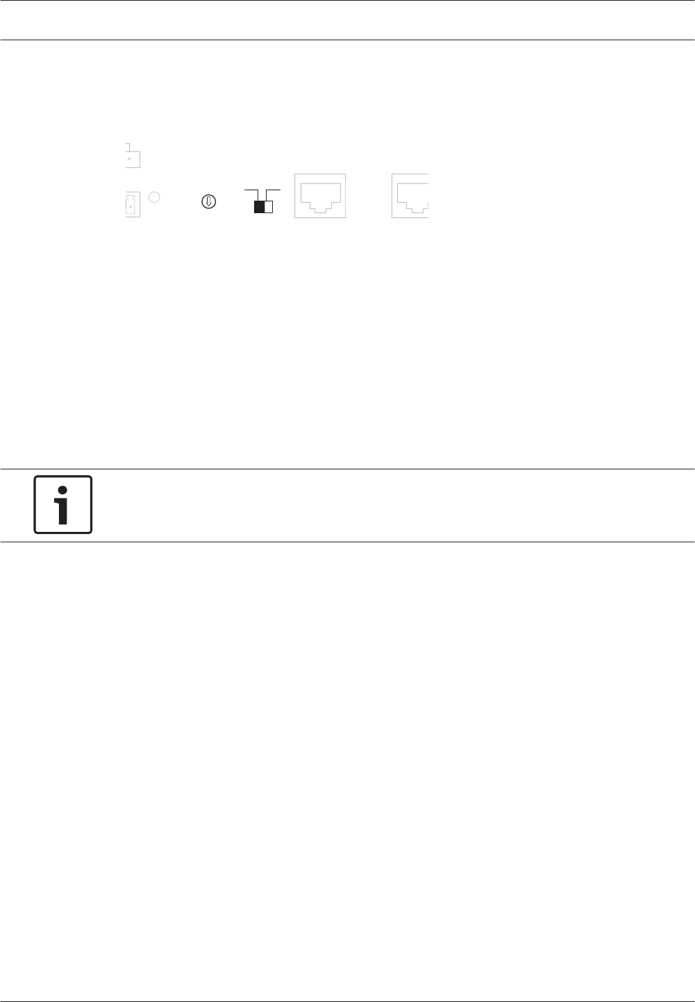
Remote control extension
The remote control extensions are configured using an ID selector and a switch:
6
1...9
ID
1
2
3
4
5
7
9
8
RCP ext. In RCP ext. Out
Off On
Termination
3
Figure 6.9: Remote control settings
Remote control extension ID
The ID of the remote control extension is set using a ID selector. The remote control extension
only controls the voice alarm router that has the same ID. Furthermore, each remote control
extension that is connected to the same remote control must have a unique ID.
Termination switch
The last remote control extension in a sequence of looped-through remote control extensions
must always be terminated. Only for these remote control extensions, put the termination
switch in the ON position.
Notice!
The Controller comes with a termination plug (RJ45). Plug this connector in the unused RJ45
socket.
6.6
6.6.1
6.6.2
86 en | Configuration Plena
2013.07 | V2.0 | Installation and Operation manual Bosch Security Systems B.V.
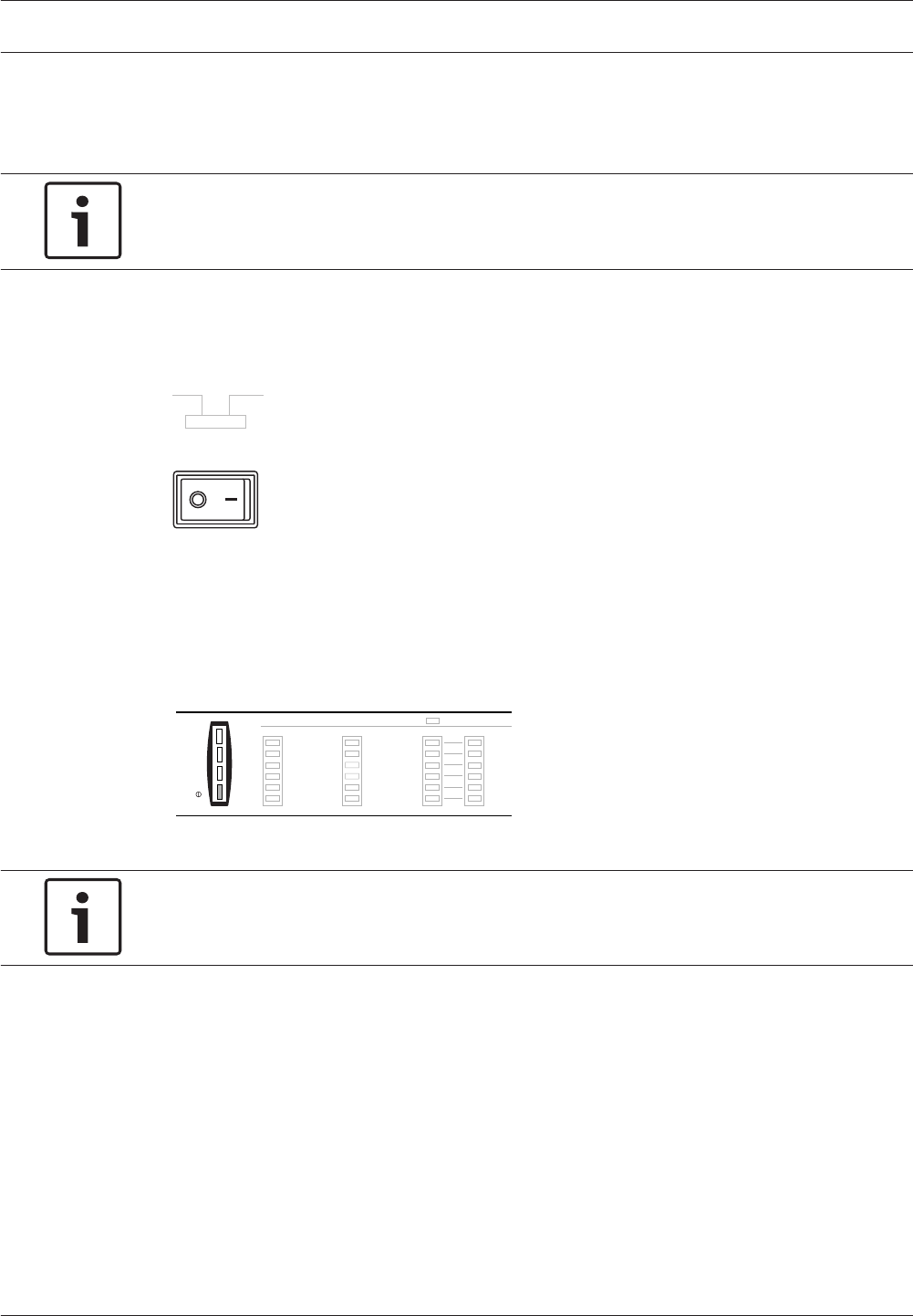
Operation
Switch on
Notice!
It is assumed that the APR mode switch (see section APR mode, page 76) is in the OFF
position.
Voice alarm controller
Switch on
Put the power switch on the rear of the voice alarm controller in the I position.
115V~ 230V~
Apparatus delivered
Connected for 230V~
Power
Figure 7.1: Power switch
If mains power or back‑up power is available, the power indicator on the front of the voice
alarm controller is lit. If the system contains call stations, the power indicator of the call
stations are also lit (see Controls, connectors and indicators, page 23, no. 1). Furthermore, all
connected remote controls and remote control extensions are switched on by the voice alarm
controller.
Processor reset
Network
Call/EMG
Music/Spare
Ground short
Input
Mains
Battery
Zone1
Zone2
Zone3
Zone4
Zone5
Zone6
Fault Indicators
AB
Disabled
Message
EMG mic
RCP
Router
0 dB
-6dB
-20dB
Figure 7.2: Power indicator
Notice!
When the system is switched on for the first time and supervision is enabled, calibrate the
system (see section Calibration, page 87).
Voice alarm router
Switch on
Put the power switch on the rear of the voice alarm router in the I position.
Calibration
Calibration is necessary for a correct loudspeaker line impedance supervision (see section
Line supervision, page 80). To calibrate the system, push the calibration switch on the rear of
the voice alarm controller (see Controls, connectors and indicators, page 14, no. 24). The
system must be calibrated:
– When the voice alarm controller is switched on for the first time.
– When a voice alarm router is switched on for the first time.
– After the connected loudspeakers are changed.
– After loudspeakers have been added or removed.
7
7.1
7.1.1
7.1.2
7.1.3
Plena Operation | en 87
Bosch Security Systems B.V. Installation and Operation manual 2013.07 | V2.0 |
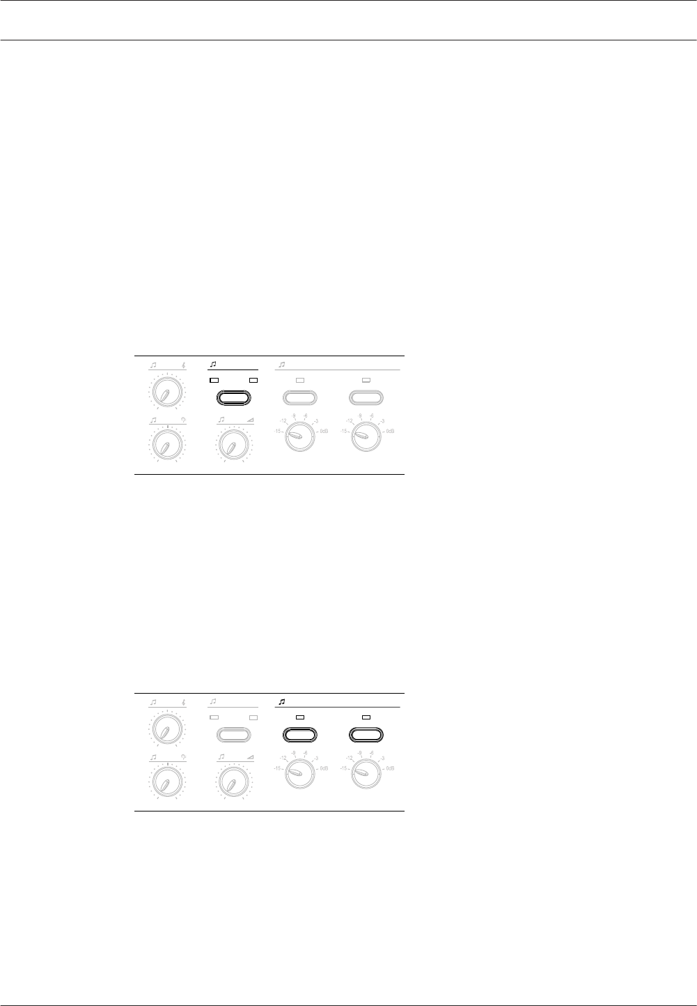
– After the settings of the connected loudspeakers have been changed.
Background music
The background music (BGM) is controlled using the BGM controls on the front of the voice
alarm controller, voice alarm router and their remote control and remote control extensions.
Proceed as follows to route BGM:
1. Select the BGM source (see section Select BGM source, page 88).
2. Select the zones (see section Select zones, page 88).
Select BGM source
Select the BGM source with the Select button on the front of the voice alarm controller. A
green LED indicates the source that is selected.
– If the source is a CD player or a tuner that is connected to the CD/Tuner input, choose
CD/Tuner.
– If the source is an auxiliary source that is connected to the Aux input, choose Aux.
0
-+
-+
CD/Tuner Aux
Select Zone select
Figure 7.3: BGM source selector
Select zones
The BGM is distributed to the zones with the Zone select buttons on the voice alarm
controller, voice alarm router, remote controls and remote control extensions. A green LED
indicates the zones to which BGM is distributed.
– If the Zone select indicator is off, no BGM is distributed to the zone. Push the Zone select
button to distribute the BGM to the zone.
– If the Zone select indicator is on, BGM is distributed to the zone. Push the Zone select
button to stop distributing the BGM to the zone.
Zone select
0
-+
-+
CD/Tuner Aux
Select
Figure 7.4: BGM zone selector
7.2
7.2.1
7.2.2
88 en | Operation Plena
2013.07 | V2.0 | Installation and Operation manual Bosch Security Systems B.V.
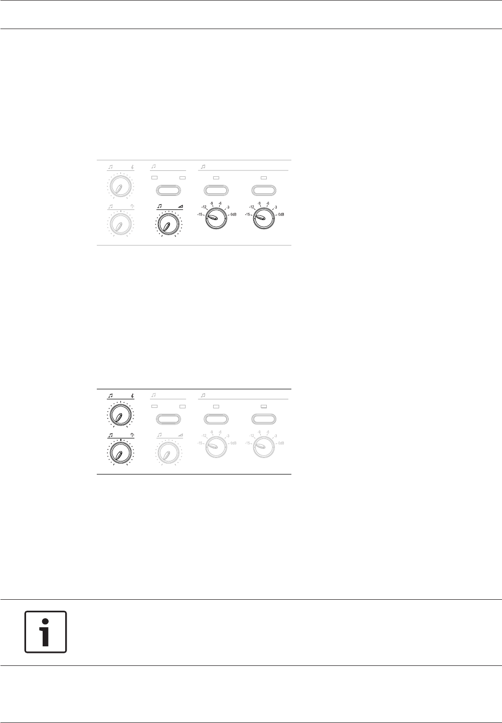
Adjust volume
The voice alarm controller has two types of controls to adjust the BGM volume. The overall
(maximum) volume of the BGM source is set with the master volume control, which is located
below the BGM source selector (Select button, see Select BGM source, page 88). Per zone that
is connected to the voice alarm controller, the local volume can be adjusted with the zone
volume switches, which are located below the zone selection buttons (Zone select, see Select
zones, page 88). Each zone volume switch has six settings, ranging between 0 dB and -15 dB.
0
-+
-+
CD/Tuner Aux
Select Zone select
Figure 7.5: BGM volume controls
The local volume in the zones that are connected to voice alarm routers must be adjusted
using local volume controls that must be connected to the loudspeaker line of each individual
zone.
Adjust frequencies
The voice alarm controller has two rotary knobs to adjust the sound of the BGM.
– Use the upper rotary knob to adjust the treble or high frequency content of the BGM.
– Use the lower rotary knob to adjust the bass or low frequency content of the BGM.
0
-+
-+
CD/Tuner Aux
Select Zone select
Figure 7.6: BGM tone controls
Business calls
Business calls can only be distributed with call stations. It is not possible to use a hand-held
emergency microphone to distribute business calls. Proceed as follows to distribute a
business call:
1. Select the zones (see section Select zones, page 90).
2. Make the announcement (see section Make the announcement, page 90).
Notice!
It is also possible to distribute business calls using business trigger inputs. When an business
trigger input is activated, the system automatically takes the action that is programmed with
the configuration software.
7.2.3
7.2.4
7.3
Plena Operation | en 89
Bosch Security Systems B.V. Installation and Operation manual 2013.07 | V2.0 |
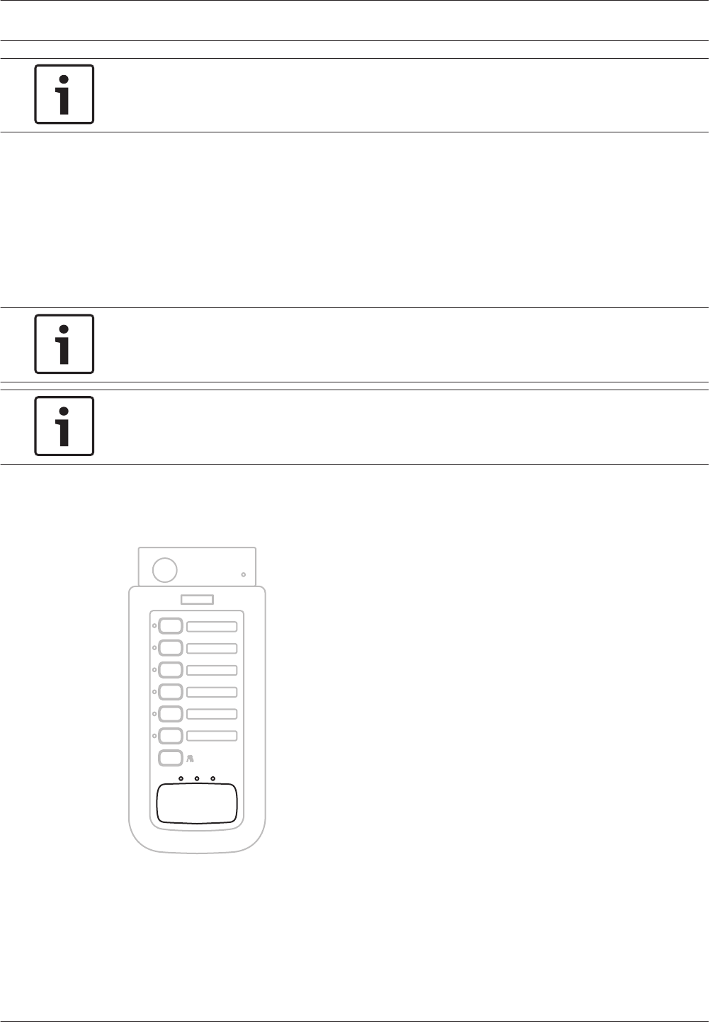
Notice!
See the Configuration Software Manual for more information about the configuration
software.
Select zones
Select the zones to which the business call must be distributed with the zone selection
buttons on the call station or its keypads. A green LED indicates the zones to which the
business call is distributed.
– If the indicator of a button is off, the zone is not selected. Push the button to select the
zone.
– If the indicator of a button is on, the zone is selected. Push the button to deselect the
zone.
Notice!
The zone selection buttons of the call stations and call station keypads must be configured
with the configuration software.
Notice!
See the Configuration Software Manual for more information about the configuration
software.
Make the announcement
Push the push‑to‑talk (PTT) button of the call station to make an announcement. The call is
only distributed to the selected zones.
Figure 7.7: PTT button and indicators
The LEDs above the PTT button provide information about the status of the call station.
7.3.1
7.3.2
90 en | Operation Plena
2013.07 | V2.0 | Installation and Operation manual Bosch Security Systems B.V.
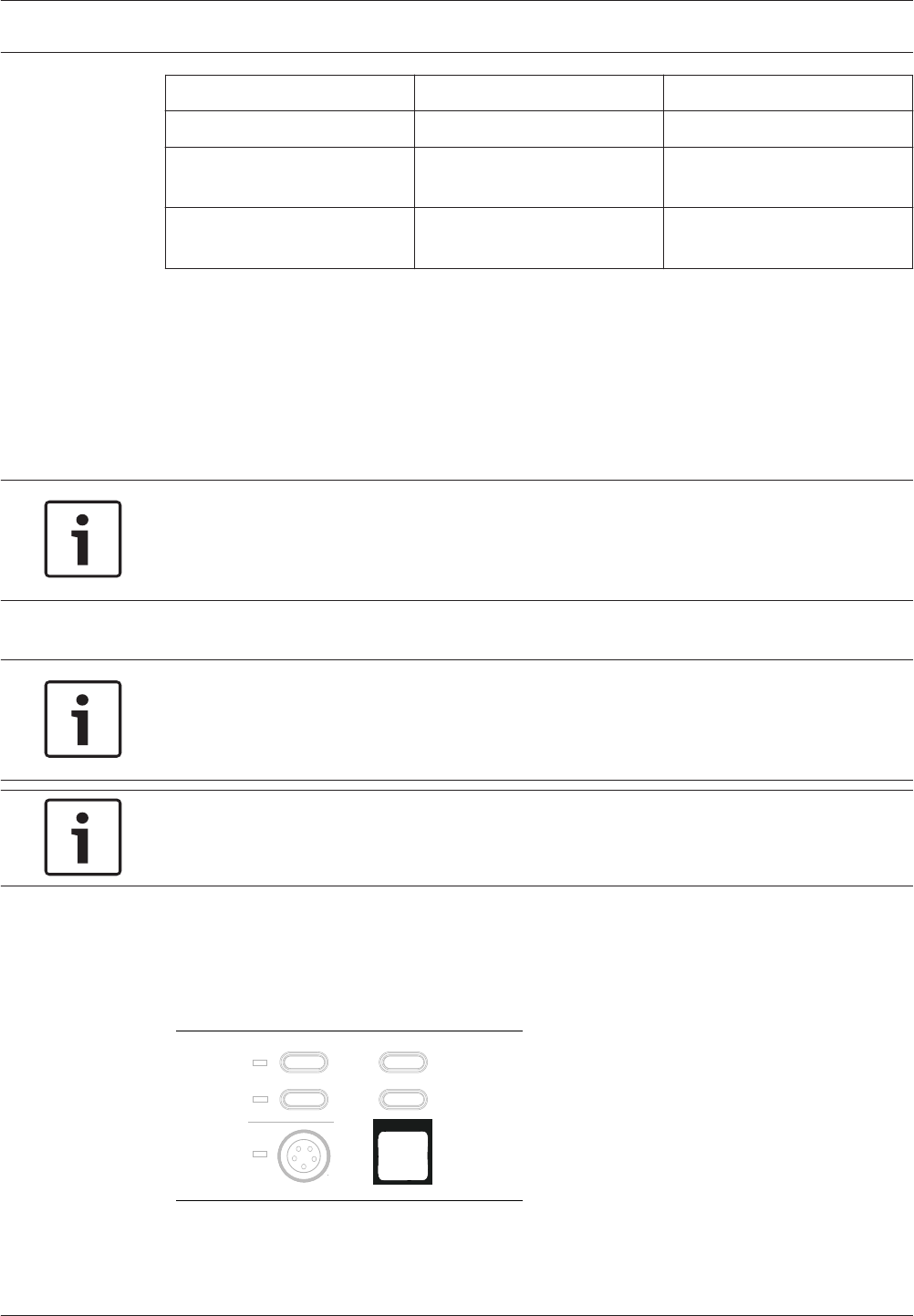
Indicator Position Description
Yellow Left System fault
Green Center Talk (green). Busy (Yellow
flashing).
Red Right System in emergency state,
call station disabled
Table 7.1: Call station status indicators
Emergency state
Emergency calls can only be distributed when the system is in the emergency state. See
section Enter the emergency state, page 91 for information about entering the emergency
state. In the emergency state, it is possible to distribute the following emergency calls:
– Live speech with the emergency microphone of the voice alarm controller or remote
controls (see section Distribute live speech, page 92).
Notice!
It is not possible to distribute chimes or speech with the call station when the system is in
the emergency state, because the call station is disabled automatically at the moment that
the system enters the emergency state.
– The default alert message (see section Distribute the alert message, page 94).
– The default alarm message (see section Distribute the alarm message, page 96).
Notice!
It is also possible to distribute emergency calls using emergency trigger inputs. When an
emergency trigger input is activated, the system automatically enters the emergency state
and takes the action that is programmed with the configuration software.
Notice!
See the Configuration Software Manual for more information about the configuration
software.
Enter the emergency state
To enter the emergency state, push the emergency button on the front of the voice alarm
controller or the remote controls. The red LED that is integrated in the switch lights. The
emergency state can also be entered by pushing the Emergency button on the fireman’s panel.
Indicator test
EMG mic
Alert message
Alarm message
All call
Figure 7.8: Emergency button
7.4
7.4.1
Plena Operation | en 91
Bosch Security Systems B.V. Installation and Operation manual 2013.07 | V2.0 |
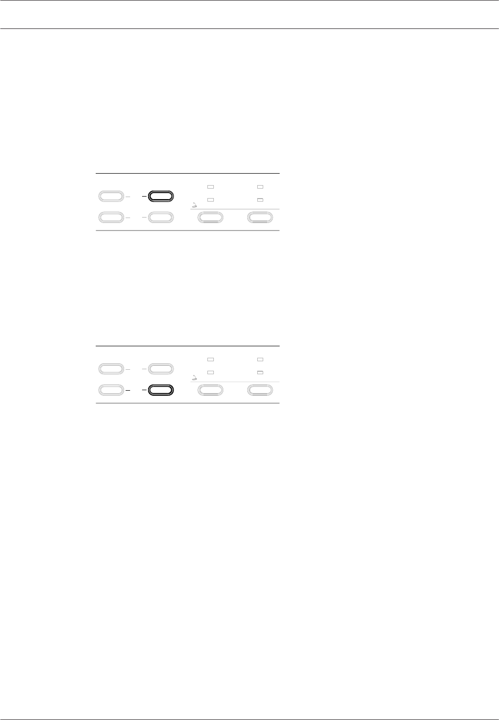
At the moment the emergency state is entered, a beeper starts and the EMG status output
contact are closed. See section Exit the emergency state, page 92 for information about
exiting the emergency state.
Acknowledge the emergency state
The beeper can be switched off by acknowledging the emergency state with the EMG Ack
button on the voice alarm controller or the remote controls. The beeper can also be switched
off by acknowledging the emergency state with the Emergency Acknowledge button on the
fireman’s panel.
Zone select
Zone1 Zone2
Fault
Reset
EMG
Ack
Figure 7.9: EMG Ack button
Exit the emergency state
Exit (reset) the emergency state by pushing the EMG Reset button on the voice alarm
controller or the remote controls. The emergency state can also be reset with the Emergency
Reset button on the fireman’s panel. In order to reset the emergency state, it first must be
acknowledged (see section Acknowledge the emergency state, page 92).
Zone select
Zone1 Zone2
Fault
Reset
EMG
Ack
Figure 7.10: EMG Reset button
Distribute live speech
Proceed as follows to distribute live speech:
1. Select zones (see section Select zones, page 93).
2. Make announcement (see section Make the announcement, page 94).
7.4.2
7.4.3
7.4.4
92 en | Operation Plena
2013.07 | V2.0 | Installation and Operation manual Bosch Security Systems B.V.

Select zones
Select the zones to which the live speech must be distributed with the Zone select buttons on
the front of the voice alarm controller or the remote controls. A red LED indicates the zones to
which the live speech is distributed.
– If the indicator of a Zone select button is off, the zone is not selected. Push the button to
select the zone.
– If the indicator of a Zone select button is on, the zone is selected. Push the button to
deselect the zone.
Notice!
If no additional action is taken within 10 seconds after the last Zone select button has been
pushed (for example closing the PTT switch), the zone selection is cancelled.
Zone select
Zone1 Zone2
Fault
Reset
EMG
Ack
Figure 7.11: Zone select buttons
To select all zones, push the All call buttons on the front of the voice alarm controller or the
remote controls.
Indicator test
EMG mic
All call
Alert message
Alarm message
Figure 7.12: All call button
7.4.5
Plena Operation | en 93
Bosch Security Systems B.V. Installation and Operation manual 2013.07 | V2.0 |
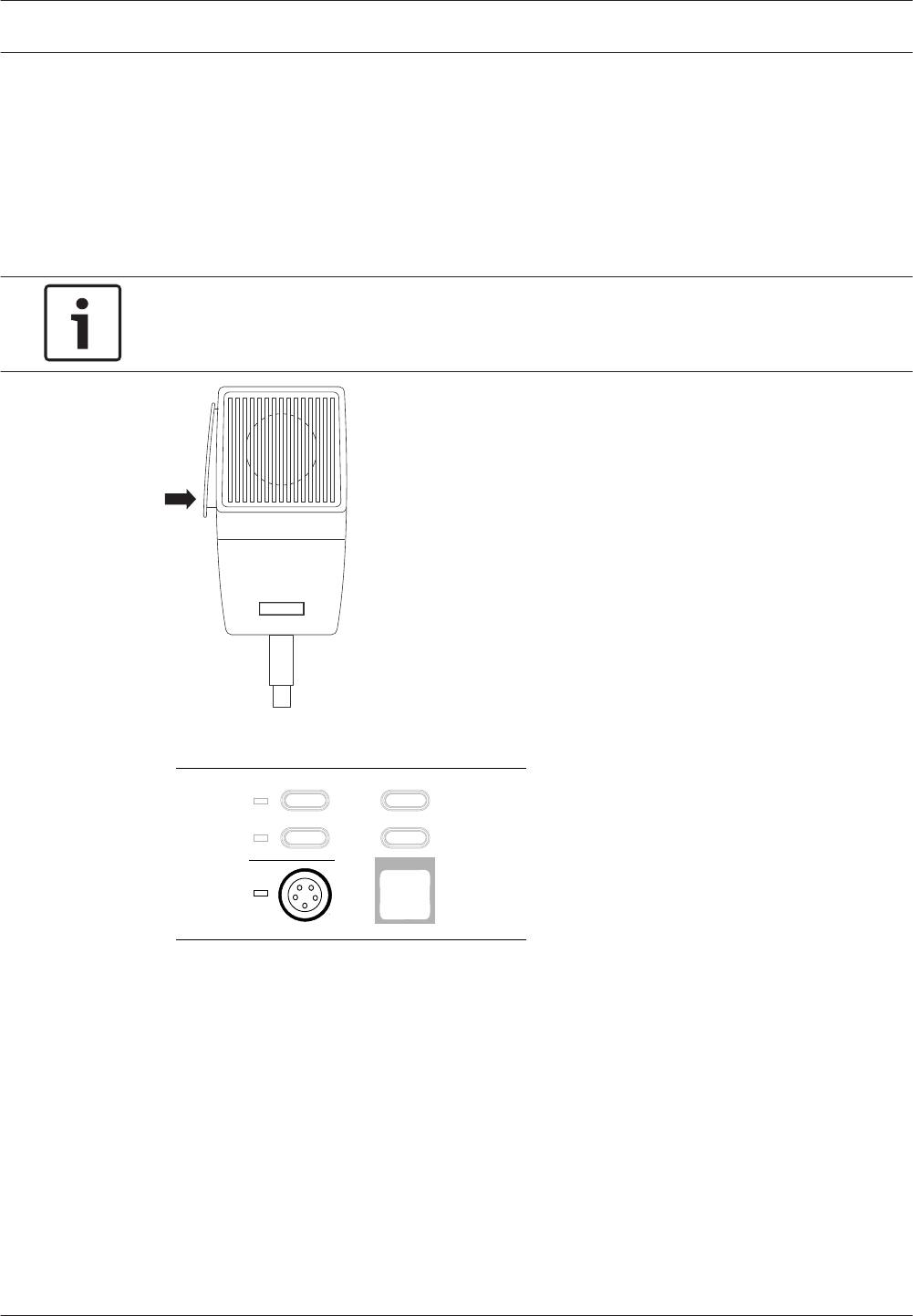
Make the announcement
Push the push‑to‑talk (PTT) button of the emergency microphone to make an announcement.
The live speech is only distributed to the selected zones (see section Select zones, page 93). At
the moment the PTT button of the emergency microphone is pushed:
– The red EMG mic indicator is lit.
– If they are currently distributed, the default alert message and default alarm message are
stopped.
Notice!
If no zones have been selected, the live speech is automatically distributed to all zones in the
system.
Figure 7.13: Emergency microphone
Indicator test
EMG mic
Alert message
Alarm message
All call
Figure 7.14: Emergency microphone indicator
Distribute the alert message
Proceed as follows to distribute the default alert message:
– Select the zones.
– Start the alert message.
Select zones
Select the zones to which the default alert message must be distributed with the Zone select
buttons on the front of the voice alarm controller or the remote controls. A red LED indicates
the zones to which the default alert message is distributed.
– If the indicator of a Zone select button is off, the zone is not selected. Push the button to
select the zone.
– If the indicator of a Zone select button is on, the zone is selected. Push the button to
deselect the zone.
7.4.6
7.4.7
94 en | Operation Plena
2013.07 | V2.0 | Installation and Operation manual Bosch Security Systems B.V.
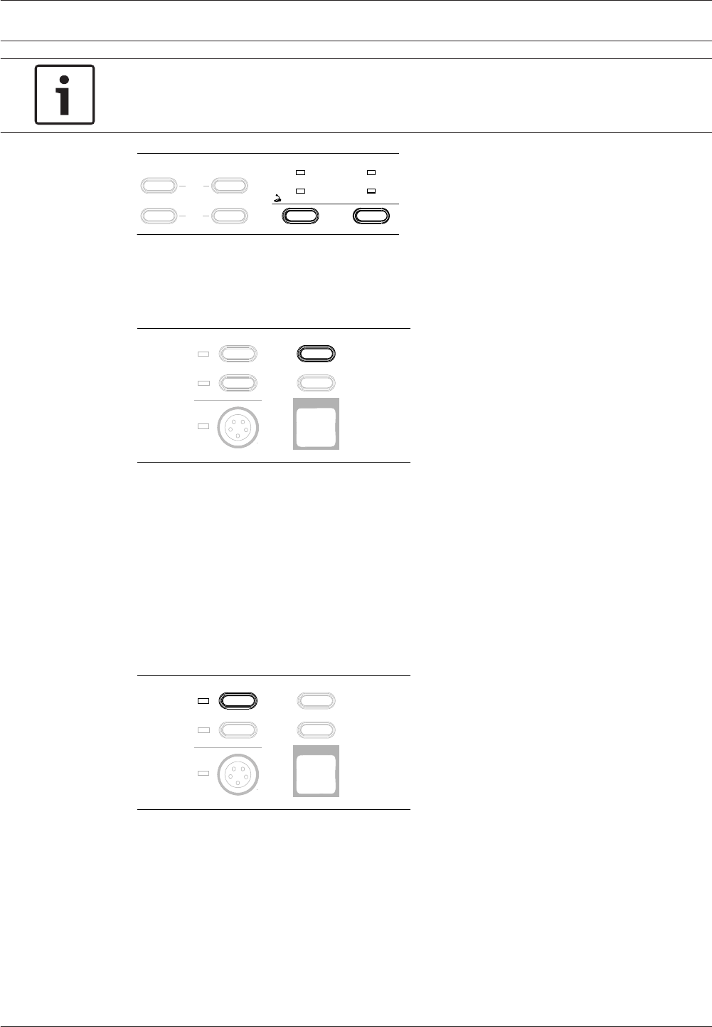
Notice!
If no additional action is taken within 10 seconds after the last Zone select button has been
pushed (for example pushing the Alert message button), the zone selection is cancelled.
Zone select
Zone1 Zone2
Fault
Reset
EMG
Ack
Figure 7.15: Zone select buttons
To select all zones, push the All call button on the front panel of the voice alarm controller or
the remote controls.
Indicator test
EMG mic
All call
Alert message
Alarm message
Figure 7.16: All call button
Start the alert message
Push the Alert message button on the front of the voice alarm controller or the remote
controls to distribute the default alert message. The message is only distributed to the
selected zones.
– If the red Alert message indicator is off, the alert message is not distributed. Push the
Alert message button to distribute the default alert message.
– If the red Alert message indicator is on, the message is distributed. Push the Alert
message button to stop distributing the default alert message.
Indicator test
EMG mic
Alarm message
All call
Alert message
Figure 7.17: Alert message button
Plena Operation | en 95
Bosch Security Systems B.V. Installation and Operation manual 2013.07 | V2.0 |
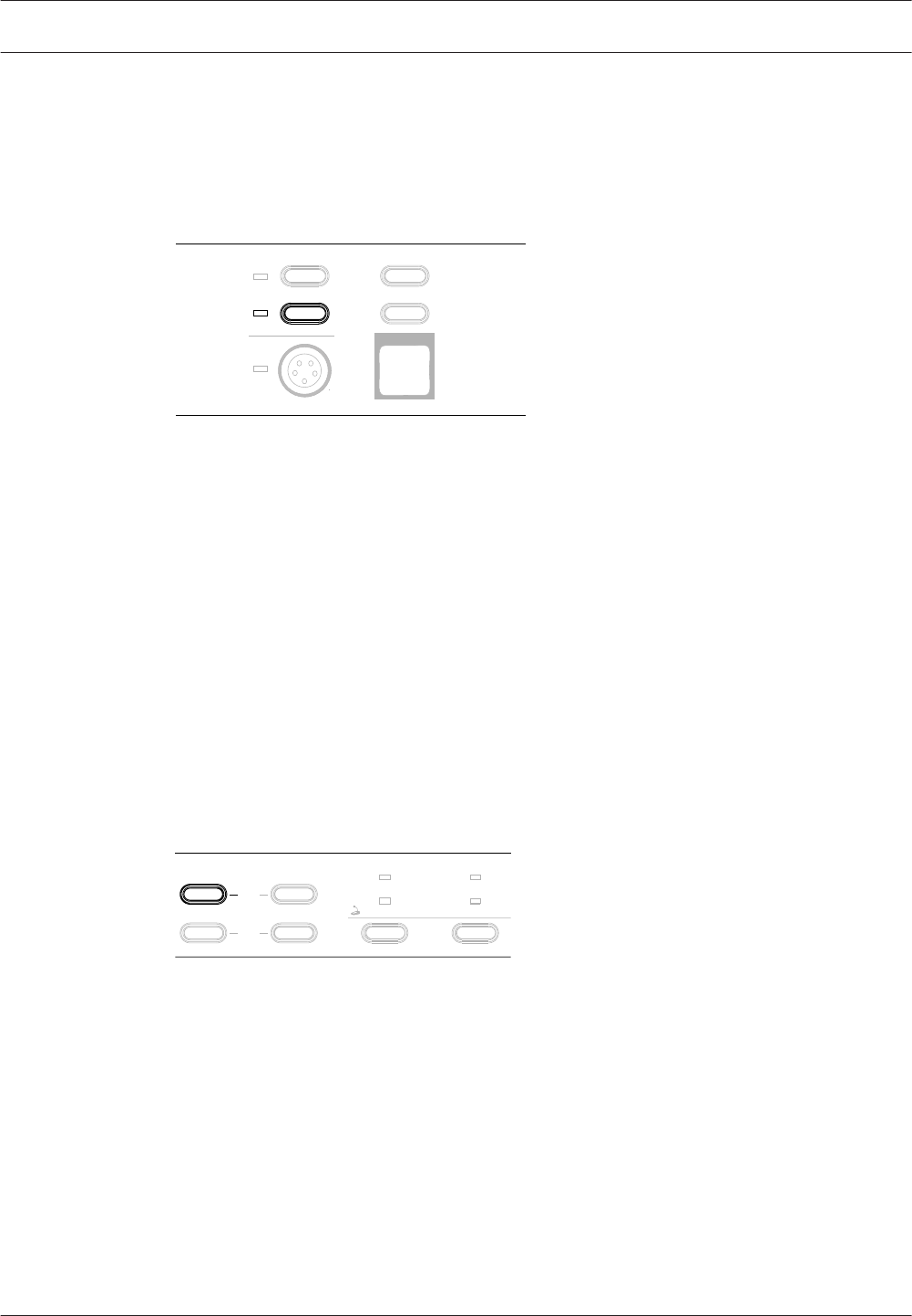
Distribute the alarm message
Distributing the default alarm message is similar to distributing the default alert message (see
section Distribute the alert message, page 94). Push the Alarm message button instead of the
Alert message button. The alarm message can also be distributed by pushing the Alarm
Message button on the fireman’s panel.
Indicator test
EMG mic
All call
Alert message
Alarm message
Figure 7.18: Alarm message button
Fault State
If a supervised function fails, the system enters the fault state and:
– Starts a beeper. The beeper is switched off when the fault is acknowledged (see section
Acknowledge the fault state, page 96).
– Closes the Fault Status NO output contacts. These status output contact is opened again
when the fault is reset (see section Reset the fault state, page 97).
– Lights a fault indicator on the front panels that indicates the source of the fault (see Fault
indicators, page 98). The indicator is switched off when the fault is reset (see section
Reset the fault state, page 97).
Acknowledge the fault state
The beeper can be switched off by acknowledging the fault state with the Fault Ack button on
the front of the voice alarm controller or the remote controls. The fault state can also be
acknowledged by pushing the Fault Acknowledge button on the fireman’s panel.
Zone select
Zone1 Zone2
Fault
Reset
EMG
Ack
Figure 7.19: Fault Ack button
The following buttons also acknowledge the fault state and stop the beeper:
– Alert message button.
– Alarm message button.
– PTT button of the emergency microphone.
7.4.8
7.5
7.5.1
96 en | Operation Plena
2013.07 | V2.0 | Installation and Operation manual Bosch Security Systems B.V.

Reset the fault state
Reset the fault state by pushing the Fault Reset button on the front of the voice alarm
controller or the remote controls. The fault state can also be reset by pushing the Fault Reset
button on the fireman’s panel. In order to reset the fault state, it first must be acknowledged
(see section Acknowledge the fault state, page 96).
When the Fault Reset button is pushed, the fault indicators are switched off and the status of
the system is checked.
– If the fault is not resolved, the fault indicators are switched on again. The beeper remains
off. It is only switched on if a new fault occurs or if the resolved fault occurs again.
– If the fault is resolved, the fault indicators remain off.
Zone select
Zone1 Zone2
Fault
Reset
EMG
Ack
Figure 7.20: Fault reset button
7.5.2
Plena Operation | en 97
Bosch Security Systems B.V. Installation and Operation manual 2013.07 | V2.0 |
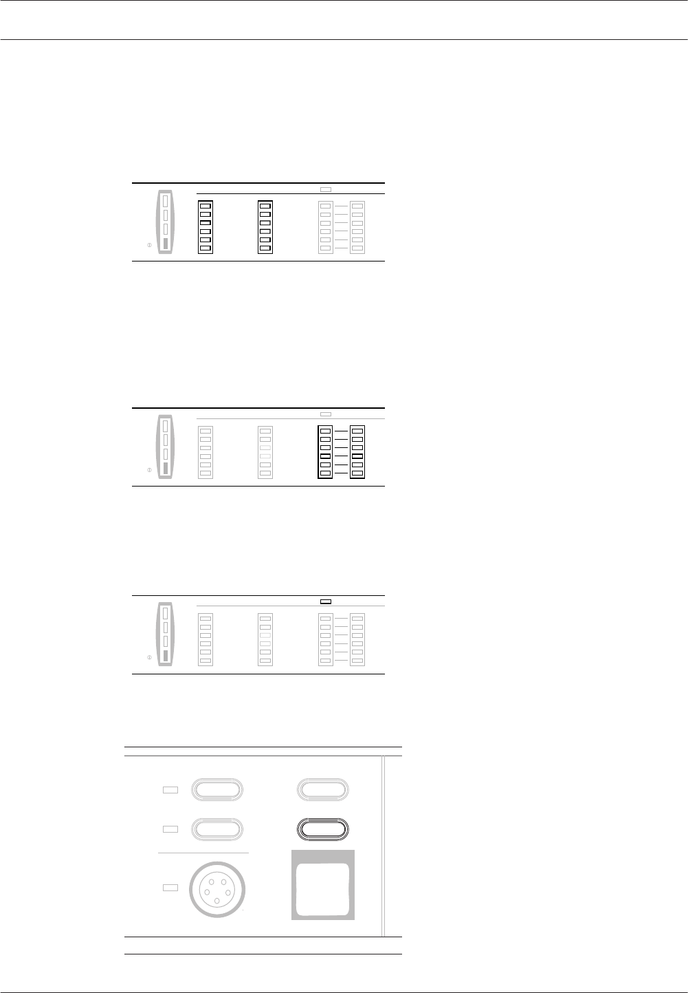
Fault indicators
The voice alarm controller, voice alarm router and remote controls have two types of fault
indicators: System fault indicators and loudspeaker line fault indicators (see Supervision, page
78). The system fault indicators provide information about failing system functions that are
supervised. If a system fault is persistent, contact your Bosch representative.
Zone1
Zone2
Zone3
Zone4
Zone5
Zone6
AB
Disabled
0 dB
-6dB
-20dB
Processor reset
Network
Call/EMG
Music/Spare
Ground short
Input
Mains
Battery
Fault Indicators
Message
EMG mic
RCP
Router
Figure 7.21: System fault indicators
The loudspeaker line indicators provide information about failing loudspeaker lines. They
indicate short-circuit and impedance supervision faults (see section Line supervision, page 80).
If a loudspeaker line indicator lights, check the wiring of the indicated loudspeaker line and try
to solve the fault. If it not possible to determine the fault, contact your Bosch representative.
Processor reset
Network
Call/EMG
Music/Spare
Ground short
Input
Mains
Battery
Fault Indicators Disabled
Message
EMG mic
RCP
Router
0 dB
-6dB
-20dB
Zone1
Zone2
Zone3
Zone4
Zone5
Zone6
AB
Figure 7.22: Loudspeaker line indicators
If supervision is disabled (see section Supervision, page 78), the fault indicators do not
function and the Disabled indicator is lit:
Processor reset
Network
Call/EMG
Music/Spare
Ground short
Input
Mains
Battery
Zone1
Zone2
Zone3
Zone4
Zone5
Zone6
Fault Indicators
AB
Disabled
Message
EMG mic
RCP
Router
0 dB
-6dB
-20dB
Figure 7.23: Disabled indicator
The availability of the indicators can be tested with the Indicator test button:.
Indicator test
EMG mic
Alert message
Alarm message
All call
Figure 7.24: Indicator test button
7.5.3
98 en | Operation Plena
2013.07 | V2.0 | Installation and Operation manual Bosch Security Systems B.V.

Indicator Description Recommended action Additional information
Processor
reset
A processor reset is
detected.
Switch the voice alarm
controller off and on
again.
See section Processor
reset, page 79.
Network A network fault is
detected.
Check all network
connections and the
network configuration.
See section Call station,
page 50 and section
Voice alarm router, page
82, section Voice alarm
routers, page 51 and
section Call station, page
83.
Call/EMG The call power amplifier
failed.
In 1-channel
mode:Switch the voice
alarm controller off and
on again.In 2-channel
mode:Switch the
external power amplifies
off and on again.
See section External
power amplifier, page 52,
section External power
amplifiers, page 67 and
section 1-Channel mode
operation, page 77 and
section 2-Channel mode
operation, page 78.
Music/Spare The BGM power
amplifier failed.
In 1-channel
mode:Switch the
external power
amplifiers off and on
again.In 2- channel
mode:Switch the voice
alarm controller off and
on again.
See section External
power amplifier, page 52,
section External power
amplifiers, page 67 and
section 1-Channel mode
operation, page 77 and
section 2-Channel mode
operation, page 78.
Ground short A short-to-ground fault
in the loudspeaker line
cabling is detected.
Check all loudspeaker
lines for short-to-ground
situations.
See section
Loudspeakers, page 54
and section Line
supervision, page 80.
Input fault in the connection
to an emergency trigger
input is detected.
Check the connections
to all supervised
emergency trigger
inputs.
See section Voice Alarm
Controller, page 106 and
section Emergency
trigger inputs, page 80.
Mains A mains power failure is
detected.
Check the mains power
connection of the voice
alarm controller and the
mains power availability.
See section Power, page
62 and section Mains
power, page 80.
Battery A back-up power failure
is detected.
Check the back-up
power supply
connection of the voice
alarm controller and the
back-up power
availability.
See section Power, page
62 and section Battery,
page 80.
Plena Operation | en 99
Bosch Security Systems B.V. Installation and Operation manual 2013.07 | V2.0 |

Indicator Description Recommended action Additional information
Message A message fault is
detected.
Switch the voice alarm
controller off and on
again.
See section Message
supervision, page 80.
EMG mic An emergency
microphone fault is
detected.
Check the emergency
microphone. If
necessary, replace it.
See section Emergency
microphone, page 49 and
section Emergency
microphone, page 80.
RCP A remote control panel
fault is detected.
Contact your dealer. This fault should not
occur, since this type of
supervision is disabled.
Router A router fault is
detected.
The indicated fault was
not detected in the voice
alarm controller, but in a
voice alarm router.
Check the voice alarm
routers.
Table 7.2: System fault indicators
100 en | Operation Plena
2013.07 | V2.0 | Installation and Operation manual Bosch Security Systems B.V.

Troubleshooting
Introduction
Although the Plena Voice Alarm System is simple and easy in general, still questions may arise.
Maybe because of inexperience or maybe because of exploring limits of what the Plena Voice
Alarm System can do. In practice often the same questions reoccur. In other cases questions
can be foreseen. An attempt was made to put al these questions on paper, so there is no need
to ask them anymore. The answers are here already and the questions are listed by symptom.
If necessary, refer to Fault indicators, page 98 for information on the system fault indicators.
Message or chime does not sound
First check if all messages (and wave files) were downloaded using the option Upload
messages and configuration. You should do this when ANY message or wave file is changed. If
this is omitted even messages that are unchanged may stop working.
Some wave files are known to contain a proprietary block of data which cannot be interpreted
by the Plena Voice Alarm System Controller. This block of data is called a PAD chunk. This PAD
chunk can easily be removed by first loading the wave file into Audacity and then saving it
again without modifying. Audacity will save it without the PAD chunk. Audacity is a free
software tool that could be downloaded from the Plena Voice Alarm System product related
information on www.boschsecurity.com.
No pilot tone detected on EOL board
The EOL board only works on a 2-channel system. Pilot‑tone detection will also fail in a
Controller zone when BGM is selected and BGM is attenuated more than -9 dB with the rotary
volume control. Also when a call is going on the pilot‑tone will be absent on zones without call
and BGM. Fault detection on the Plena Voice Alarm System will ignore this if properly
configured.
No pilot tone detected on power amplifier
This may happen when the 100 V slave input is used and the 0 V and 100 V connections are
swapped.
Another possibility is when the 100 V slave input is used and no Call or BGM is present on the
100 V input (from the 100 V A or B line). When you want to use pilot tone supervision be sure
to use 2‑channel mode and define the fault trigger input as EOL supervision input.
No BGM on the router
Please be aware that the 70 V terminal of the Booster 1 input should be connected to the 70 V
output of the Power Amplifier. If this omitted there will not be BGM on the zones of the
router.
No BGM on controller or router
This can happen when there is an amplifier failure, for instance in a 1‑channel system without
using a spare amplifier. If supervision of the spare amplifier is nevertheless enabled a fault is
detected and BGM will be disabled. Check for the amplifier fault and rectify the problem, for
instance by correcting the configuration or replacing the defective unit.
8
8.1
8.2
8.3
8.4
8.5
8.6
Plena Troubleshooting | en 101
Bosch Security Systems B.V. Installation and Operation manual 2013.07 | V2.0 |
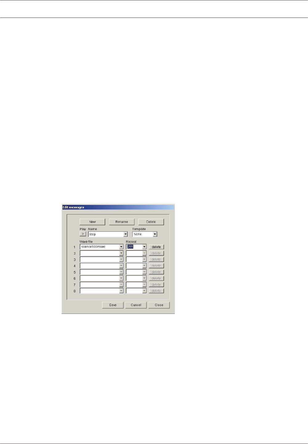
No sound coming from the router
Please check, if you are using a Plena Power Amplifier 720/480W, if the Line signal is
connected to the Program Input. If the line signal is connected to the Priority Input instead of
the Program Input there will be no output signal on the amplifier’s loudspeaker output.
Volume override only working for EMG, not for business calls
(or similar problems)
Confusion can arise in 2‑channel operation. In contradiction to what one would expect volume
override will be active in zones without BGM when no call is active. This is sometimes wrongly
interpreted mixing up fail-safe override and power saving override.
False Ground Short fault
Please check if the 0 V and 100 V connections are swapped. Swapping these could cause a
false ground short fault appearing and disappearing at unpredictable moments and events.
Start/Stop function on Trigger Inputs
This is a functionality which is not really intended at the moment, but may be desired by the
user. Program a message which consists of a silent wave file, with the maximum repeat of 255.
Name it Stop.
Figure 8.1: Silent wave file message
Since the Start action on the trigger input needs to be latched the Trigger Type under Action
Programming > Controller > EMG Trigger/Fault Detector should be set to Toggle. Configure the
alarm message for the Trigger Input which you want to be used for the Start function.
Configure the silent message named Stop for the Trigger Input you want to use for the Stop
function. Select All Zones for its Zone Selection. The priority must be higher than the priority
of the Trigger Inputs used for Start.
When the alarm is stopped with the Trigger Input Stop all zones will be silent but the system
will still be in Emergency State. The end user then needs to press Emergency Acknowledge
and Emergency Reset to terminate this Emergency State.
8.7
8.8
8.9
8.10
102 en | Troubleshooting Plena
2013.07 | V2.0 | Installation and Operation manual Bosch Security Systems B.V.

Processor Reset
This fault can occur when the Service DIP Switches are left in the wrong position. This
frequently occurs when people have downloaded new firmware. The correct positions should
be SEL0 and SEL1 to on, and Enable Firmware Download to off.
The fault indication for Processor Reset cannot be disabled, neither in the configuration nor
with the dipswitch Supervision at the back of the Controller.
USB port not connected
This error message can occur when the Configuration Software is just installed. Although
there is no such instruction displayed during installation it is recommended that your PC is
rebooted after installing the Configuration Software.
This problem could also occur when the Service DIP Switches are in the wrong position. A
more common problem in such a case is a Processor Reset Fault. However if fault supervision
is disabled this fault indication will not occur and USB port not connected could occur. Please
refer to the section Processor Reset for more information.
Data fault during configuration upload
This fault occurs when the Configuration Software you are using and the Firmware on the
Controller to which you are uploading have a different incompatible version.
A click sounds through the loudspeakers at regular intervals
In a very silent environment like meeting rooms and offices, especially when they are
abandoned, a small click can be heard at the start and end of an impedance measurement.
This click is simply caused by the 20 kHz pilot tone being switched on and off. The level of the
click is small, but also depends on cable parameters, loudspeaker characteristics and load. If
the click, no matter how weak it is, is unacceptable then end of line supervision using the EOL
board should be considered instead of impedance supervision.
Password not working
A fault message, like indicated below, occurs when data used by the Configuration Software is
corrupted. It sometime happens after a software upgrade or when different versions of the
Configuration Software have been installed on your PC.
To fix it uninstall all versions of Configuration Software and (only) reinstall the version you will
use.
Configuration download fails
Figure 8.2: Downloading window
8.11
8.12
8.13
8.14
8.15
8.16
Plena Troubleshooting | en 103
Bosch Security Systems B.V. Installation and Operation manual 2013.07 | V2.0 |

When the configuration download fails and the message in the window above changes to
STATUS: Downloading data failed there is a wave file in the configuration with misinterpreted
data. The file might be created with Audacity. Files created with R8brain do not suffer from
this.
Can’t retrieve the original wave files with the configuration
download
Please note that the names of wave files, messages, message templates, zones and zone
groups are not stored in the Controller and therefore cannot be retrieved. However all data is
still there in the right place leaving a correctly functioning configuration. The names taken are
default names followed by an incremental number. The default names are listed below:
Label or file type Default name
Wave file Wave#.wav
Message name Message #
Template name Template #
Controller Zone Controller Output Z#
Router Zone Router # Output Z#
Zone Group Group #
Table 8.1: Default file names
The wave files will be stored in the folder C:\Program Files\Bosch\Plena Voice Alarm System
\Configuration\Sounds\Backup, or C:\Program Files (86)\....., or C:\Bosch\Plena....
8.17
104 en | Troubleshooting Plena
2013.07 | V2.0 | Installation and Operation manual Bosch Security Systems B.V.

Maintenance
The system requires minimum maintenance.
To keep the system in good condition, do the following:
– Clean the units (section Clean the units, page 105)
– Clean the air inlets (section Clean air inlets, page 105)
– Check connectors and grounding (section Check the connectors and grounding, page
105).
!
Warning!
Dangerous mains voltages are present inside the units. Disconnect the main power supply
before you do any maintenance.
Clean the units
Periodically you must clean all units with a damp, lint-free cloth.
Clean air inlets
The 19‑inch units can collect dust as a result of the internal fans. Once a year you should use a
vacuum cleaner to clean the air inlets of all units in the 19‑inch racks.
Check the connectors and grounding
Periodically check:
– All cable connections.
– The ground (PE) connection of the system components.
9
9.1
9.2
9.3
Plena Maintenance | en 105
Bosch Security Systems B.V. Installation and Operation manual 2013.07 | V2.0 |

Technical data
Electrical
Voice Alarm Controller
Electrical
Mains voltage: 230/115 V(AC), ± 10%, 50/60 Hz
Mains current: 0.3 A (system idle)
4.0 A (maximum load)
Max. mains inrush current: 6.3 A (for mains voltage of 220 - 240 V)
10 A (for mains voltage of 100 - 120 V)
Battery voltage: 20.0 to 26.5 V(DC)
Battery current: 0.9 A (system idle)
14 A (maximum load)
Notice!
Maximum load means maximum power out, maximum load 24 V(DC) out and maximum
number of call stations.
Message manager
Data format: WAV-file, 16-bit PCM, mono
Supported sample rates (fs): 24 kHz, 22.05 kHz, 16 kHz, 12 kHz, 11.025
kHz
Frequency response:
@ fs = 24 kHz, 100 Hz - 11 kHz (+1/-3 dB)
@ fs = 22.05 kHz, 100 Hz - 10 kHz (+1/-3 dB)
@ fs = 16 kHz, 100 Hz - 7.3 kHz (+1/- 3 dB)
@ fs = 12 kHz, 100 Hz - 5.5 kHz (+1/-3 dB)
@ fs = 11.025 kHz, 100 Hz - 5 kHz (+1/-3 dB)
Distortion: < 0.1% @ 1 kHz
Signal-to-noise ratio (flat at max. volume): > 80 dB
Memory capacity: 64 Mbit Flash
Recording/playback time: 333 s @ fs = 24 kHz
Number of messages: max. 254 wave files
Supervision EEPROM: Continuous checksum control
Supervision DAC: 1 Hz pilot tone
Data retention time: > 10 years
10
10.1
10.1.1
106 en | Technical data Plena
2013.07 | V2.0 | Installation and Operation manual Bosch Security Systems B.V.

Internal power amplifier
Rated output power: 240 W
Frequency response: 100 Hz - 18 kHz (+1/-3 dB, @ -10 dB ref.
rated output)
Distortion: < 1% @ rated output power, 1 kHz
Signal-to-noise ratio (flat at max. volume): > 85 dB
Supervision: 20 kHz pilot tone
Outputs: 70, 100 V screw terminal, 100 V call out
Interconnection
Call Station: RJ45 sockets, CAN bus; max. 8 call stations
Voice Alarm Router: RJ45 socket, CAN bus; max. 9 routers
Remote controls (Fireman’s Panel, Remote
Control, Remote Control Extension):
RJ45 socket, CAN bus; max. 2 remote
controls
PC: USB 2.0 (USB 1.1 compatible)
External power amplifier: 3-pin XLR and screw terminals, max. 5 A;
max. rated output 1000 W
Loudspeaker outputs
Type: Screw terminals
Number of zones: 6
Number of loudspeaker lines: 12 (2 per zone)
Signal-to-noise ratio (flat at max. volume): > 85 dB
Line voltage: 100 V
Overrides
Type: 3-wire or 4-wire on screw terminals
Voltage: 24 V(DC) for 4-wire, if selected
Current: total 0.8 A
Trigger outputs
Type: Screw terminals
Voltage: Floating, max. 250 V
Current: max. 0.5 A
Plena Technical data | en 107
Bosch Security Systems B.V. Installation and Operation manual 2013.07 | V2.0 |

Trigger inputs / 24 V DC out
Trigger voltage: < 24 V
Type:
Momentary or latching
Normally opened (default) or normally
closed
Emergency input supervision: 10 kΩ + 10 kΩ series and parallel resistors
24 V DC out: 24 V(DC), max. 0.8 A
VOX switch: Normally opened
Mic/line input with VOX functionality
Type: 3-pin XLR, 6.3 mm jack socket, balanced
Sensitivity: 1 mV +1/-3 dB (mic), 1 V +1/-3 dB (line)
Impedance: > 10 kΩ
VOX threshold: -10 dB ref nominal input level
BGM
Type: Cinch, stereo converted to mono
Nominal input level: 500 mV
Line out
Type: 3-pin XLR, 6.3 mm jack socket, balanced
Nominal output level: 1 V
Maximum output level: 1 V
External power amplifier
Type: 3-pin XLR and screw terminals
Controller output/Amplifier input: 1 V
Controller input/Amplifier output: 100 V
108 en | Technical data Plena
2013.07 | V2.0 | Installation and Operation manual Bosch Security Systems B.V.
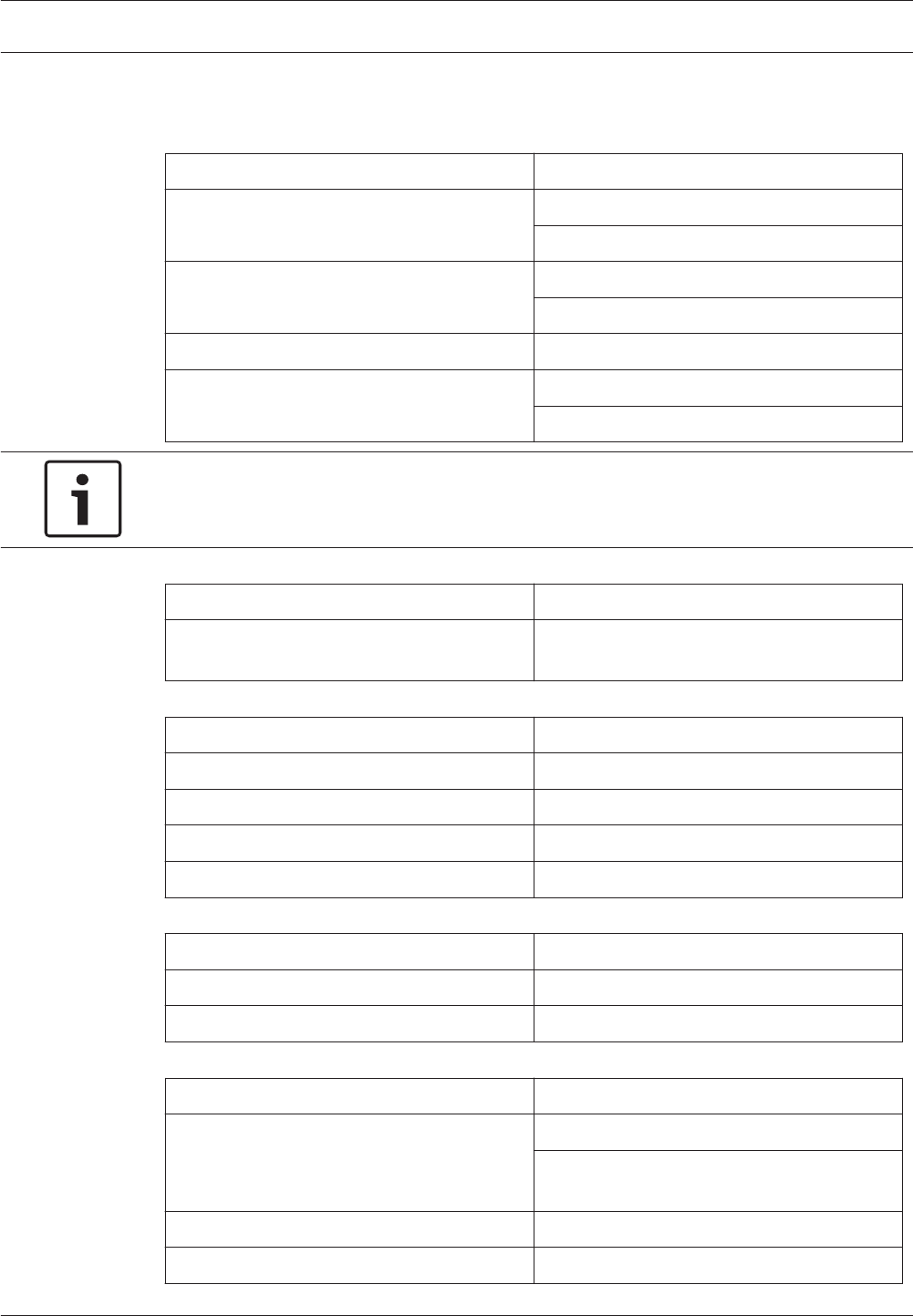
Voice Alarm Router
Electrical
Mains voltage: 230/115 V(AC), ± 10%, 50/60 Hz
Mains current: 0.2 A (system idle)
0.3 A (maximum load)
Max. mains inrush current: 1.5 A (for mains voltage of 220 - 240 V)
3 A (for mains voltage of 100 - 120 V)
Battery voltage: 20.0 to 26.5 V(DC)
Battery current: 0.5 A (system idle)
1.5 A (maximum load)
Notice!
Maximum load means maximum power out, maximum load 24 V(DC) out and maximum
number of call stations.
Interconnection
Voice Alarm Router: RJ45 socket, CAN bus; max. 2 routers
External power amplifiers: 3-pin XLR and screw terminals, max. 5 A;
max. rated output 1000 W
Loudspeaker outputs
Type: Screw terminals
Number of zones: 6
Number of loudspeaker lines: 12 (2 per zone)
Signal-to-noise ratio (flat at max. volume): > 85 dB
Line voltage: 100 V
Overrides
Type: 3‑wire or 4‑wire on screw terminals
Voltage: 24 V(DC) for 4‑wire, if selected
Current: Total 0.8 A
Trigger inputs / 24 V DC out
Trigger voltage: < 24 V
Type:
Momentary or latching
Normally opened (default) or normally
closed
Emergency input supervision: 10 kΩ + 10 kΩ series and parallel resistors
24 V DC out: 24 V(DC), max. 0.8 A
10.1.2
Plena Technical data | en 109
Bosch Security Systems B.V. Installation and Operation manual 2013.07 | V2.0 |

External power amplifiers
Type: 3-pin XLR and screw terminals
Router output/Amplifier input: 1 V
Router input/Amplifier output: 100 V
Call Station
Electrical
Voltage range: 24 V(DC), +20%/-10%, supplied by the
Controller or external power source
Current consumption: < 30 mA
Performance
Nominal sensitivity: 85 dB SPL (gain preset 0 dB)
Nominal output level: 355 mV
Maximum input sound level: 110 dB SPL
Gain preset: +6/0/-15 dB
Limiter threshold: 2 V
Compression ratio limiter: 20:1
Distortion:
< 0.6% (nominal input)
< 5% (maximum input)
Equivalent input noise level: 25 dB SPL(A)
Frequency response: 100 Hz - 16 kHz
Speech filter: - 3 dB @ 500 Hz, high-pass, 6 dB/oct
Output impedance: 200 Ω
Interconnection
Type: 2x redundant RJ45 sockets to connect the
call station to the voice alarm system
controller with CAT‑5 Ethernet cables.
Physical characteristics
Voice Alarm Controller
Dimensions: 19” wide, 3 U high, 360 mm deep
(leave 50 mm for connections)
19” mounting brackets: Included
Weight: Approx. 20 kg
10.1.3
10.2
10.2.1
110 en | Technical data Plena
2013.07 | V2.0 | Installation and Operation manual Bosch Security Systems B.V.

Voice Alarm Router
Dimensions: 19” wide, 2 U high, 250 mm deep
(leave 50 mm for connections)
19” mounting brackets: Included
Weight: Approx. 3 kg
Call Station
Dimensions: 40 x 100 x 235 (base)
390 mm stem length (with microphone)
Weight: Approx. 1 kg
Call Station Keypad
Dimensions: 40 x 100 x 235 (base)
Voice Alarm Remote Control
Current consumption:
150 mA (typical), 24 V(DC)
400 mA (indicator test), 24 V(DC)
Dimensions: 132.5 x 430 x 90 mm
Weight: 2.2 kg
Voice Alarm Remote Control Kit
Current consumption:
150 mA (idle)
400 mA (indicator test)
Dimensions: 132.5 x 430 x 90 mm
Weight: 2.2 kg
Remote Control Extension
Current consumption:
50 mA (idle)
200 mA (indicator test)
Dimensions: 88 x 432 x 90 mm
Weight: 1.8 kg
Remote Control Extension Kit
Current consumption:
50 mA (idle)
200 mA (indicator test)
Dimensions: 88 x 432 x 90 mm
Weight: 1.8 kg
10.2.2
10.2.3
10.2.4
10.2.5
10.2.6
10.2.7
10.2.8
Plena Technical data | en 111
Bosch Security Systems B.V. Installation and Operation manual 2013.07 | V2.0 |

Fireman’s Panel
Current consumption:
150 mA (idle)
400 mA (indicator test)
Dimensions: 132.5 x 430 x 90 mm
Weight: 2.2 kg
End of line detection board
Input level: 100 V rms @ program 20 Hz - 20 kHz
Pilot input level: 5 V - 50 V @ 20 kHz ± 20%
Minimum trigger level: 3.5 V
Output: Floating single trigger
Isolation: 250 Vp
Max level on open contact: 250 VDC
Response time:
Close min. 1 second
Close max. 10 seconds
Environmental conditions
Voice Alarm Controller
Operating temperature range: -10 to +55 °C
Storage temperature range: -40 to +70 °C
Relative humidity: < 95%
Voice Alarm Router
Operating temperature range: -10 to +55 °C
Storage temperature range: -25 to +55 °C
Relative humidity: < 95%
Call Station
Operating temperature range: -10 to +55 °C
Storage temperature range: -40 to +70 °C
Relative humidity: < 95%
10.2.9
10.2.10
10.3
10.3.1
10.3.2
10.3.3
112 en | Technical data Plena
2013.07 | V2.0 | Installation and Operation manual Bosch Security Systems B.V.

Standards
Voice Alarm Controller
EMC emission: According to EN55103-1
EMC immunity: According to EN55103-2
10.4
10.4.1
Plena Technical data | en 113
Bosch Security Systems B.V. Installation and Operation manual 2013.07 | V2.0 |

Appendices
Compliancy checklists
Emergency Sound Systems
Bosch Security Systems B.V. has made a great effort for the design and manufacturing of the
components and also supplies all documentation that enables the assembly of a safe and high
quality emergency unit in accordance with EN60849:1998, EN54-16:2008 and
ISO7240-16:2007. Bosch Security Systems B.V. has made up this list of requirements, based
on the standard, which needs to be filled in and subsequently signed off by both parties. The
signed paper has the nature of a certificate and can have significant meaning in the case of a
legal investigation of the liability issue for personal injuries.
– The safety of the system in accordance with EN60849:1998, EN54-16:2008 and
ISO7240-16:2007 in an alarm and emergency application does not only depend on
component safety, but also highly on the installation engineer and the operator. For
example, the sound pressure level of the system depends on the installation. Moreover,
the system should only be installed and operated by qualified personnel.
– Modifications of the system should only be executed by authorized persons in accordance
with the safety concept and need to be registered in the system documentation.
– If third party components (not delivered by Bosch Security Systems B.V.) are added to
the minimal configuration of Plena Voice Alarm System, then the EN60849:1998,
EN54‑16:2008 and ISO7240‑16:2007 certification becomes expired. This does not apply
to BGM sources or non evac features.
– Only use a UPS compliant to the current standards and legislation in combination with
the Plena Voice Alarm System.
– The end-user must maintain a journal for the system.
– The installer is responsible for security measures to prevent improper use of the system.
– Bosch Security Systems B.V. refuses any liability for damage that might result from non-
observance of these instructions.
Herewith the undersigned states that he/she has processed for him/her applicable
requirements, as specified in this document, in an adequate way and has confirmed this fact
by signing the rightmost column of each applicable requirement.
Installer End-user
Name:
Signature:
Date:
Place:
11
11.1
11.1.1
114 en | Appendices Plena
2013.07 | V2.0 | Installation and Operation manual Bosch Security Systems B.V.

List of authorized end-users
Name Name
Plena Appendices | en 115
Bosch Security Systems B.V. Installation and Operation manual 2013.07 | V2.0 |

EN60849: 1998
Valid for version 2.13.xx
4. General system requirements
Clause / Requirement Compliance Signature
4.1 Principal features
A sound system for emergency purposes
shall permit the broadcasting of
intelligible information of measures to be
taken for the protection of lives within
one or more specified areas.
Compliant, if properly installed.
The relevant article is covered by
the Plena Voice Alarm System , The
correct installation and
configuration is the responsibility
of the installer.
The following criteria shall be fulfilled:
a When any alarm is detected, the
system shall immediately disable any
functions not connected with its
emergency role (such as paging, music
or general pre-recorded
announcements being broadcast to
the loudspeaker zones requiring
emergency broadcasts).
Compliant. The EMG state can be
entered in two ways:
– When an emergency message
is started via the EMG
triggers.
– The EMG button on the front
panel, the remote control or
the Fireman's panel is
pressed.
When the EMG state is entered, all
non emergency paging and BGM is
stopped.
11.1.2
116 en | Appendices Plena
2013.07 | V2.0 | Installation and Operation manual Bosch Security Systems B.V.

Clause / Requirement Compliance Signature
b Unless damaged as a result of the
emergency, the system shall be
available for operation at all times (or
as required by the system
specification).
Compliant, if all requirements
below are fulfilled and installed
with:
– Spare Power Amplifiers.
– Multiple loudspeaker circuits
per zone or multiple zones.
– Battery back-up / UPS back-
up.
Responsibility of the installer.
– The communication bus
between Controller and
Routers and between
Controller and Remote
Controls is not redundant. If
damage or removed,
communication between these
elements is not possible. Also,
when the processor is
damaged or fails the system
will not function properly. In
that event the fault will be
clearly indicated on the
Controller, Routers (if
installed) and Remote
Controls (if Installed) Also an
audible signal is generated at
the Controller and Remote
Control. The installer must
ensure that during downtime
for repair or maintenance the
safety of the occupants is
ensured. Responsibility of the
installer to verify that proper
procedures are in place. If the
processor is defective, no
calls can be made. If the
communication bus between
routers, or between controller
and remote control is broken,
no call can be made beyond
the point of the broken
connection.
c The system shall be capable of
broadcasting within 10 s after primary
or secondary power is applied.
Compliant. It is recommended that
the Remote Control at the
fireman's entrance is programmed
to have the highest priority.
Plena Appendices | en 117
Bosch Security Systems B.V. Installation and Operation manual 2013.07 | V2.0 |

Clause / Requirement Compliance Signature
d Except during the condition described
in 4.1c), the system shall be capable
of broadcasting a first attention-
drawing signal within 3 s of being
placed in an emergency mode by the
operator, or automatically on receipt
of a signal from a fire or other
detection system. In the latter case,
the period of 3 s includes the reaction
time of the detection system from the
time the emergency is first detected,
to commanding the alarm broadcast.
Compliant. The installer is required
to ensure that the Fire detection
system does not have latency
beyond 2s to ensure that the entire
installation reacts within 3s.
Note: Reaction time of the Voice
Alarm System reacts within 1
second.
e The system shall be able to broadcast
attention-drawing signals and speech
messages to one or more areas
simultaneously. There shall be at least
one appropriate attention-drawing
signal alternating with one or more
speech messages for this purpose.
Compliant, if attention-drawing
signal is part of the configuration.
Responsibility of the installer.
Note: It is recommended that an
attention drawing signal is
assigned to the EMG button.
f At any time the system operator shall
be able to receive, by means of a
monitoring system, indications of the
correct functioning or otherwise of
the relevant parts of the emergency
system (see also 5.2 and 5.3).
Compliant.
g Failure of a single amplifier or
loudspeaker circuit shall not result in
total loss of coverage in the
loudspeaker zone served.
NOTE 1 - The monitoring system
specified in 4.1f) should indicate the
failure of an amplifier or of a
loudspeaker circuit.
NOTE 2 - Particularly in small
buildings, it may not be necessary to
install two separate loudspeaker
circuits in one loudspeaker zone. A
decision on this matter may be
subject to local regulations.
Compliant if installed with:
– Spare Power Amplifiers.
– Multiple loudspeaker circuits
per zone or multiple zones. A-
B wiring.
– Appropriate supervision on.
Responsibility of the installer.
118 en | Appendices Plena
2013.07 | V2.0 | Installation and Operation manual Bosch Security Systems B.V.

Clause / Requirement Compliance Signature
h An attention-drawing signal shall
precede the first message for 4 s to
10 s. Successive signals and messages
shall then continue until either
changed in accordance with the
evacuation procedure, or manually
silenced. The interval between
successive messages shall not exceed
30 s and attention-drawing signals
shall be broadcast whenever periods
of silence might otherwise exceed 10
s. Where more than one attention-
drawing signal is used, such as those
used for different types of emergency,
each signal shall be clearly
distinguishable in character.
Compliant, if attention-drawing
signal is part of the pre- recorded
message and the configuration has
been setup to include this signal.
Responsibility of the installer.
Note: if you deviate from this, the
system is no longer a certified
system.
i All messages shall be clear, short,
unambiguous and as far as
practicable, pre-planned.
Responsibility of the installer.
Default configuration is compliant.
Various messages are pre installed
as examples.
Where pre-recorded messages are
used they shall be held in a non-
volatile form, preferably in a solid-
state store, and be continuously
monitored for availability.
Flash memory is monitored with
checksum.
The system design shall make it
inherently impossible for an external
source to corrupt or derange the store
or its contents.
Compliant. Upload of a new
configuration via external PC is
password protected. Other
external connections are not
available.
NOTE - On grounds of reliability, it is
preferable not to use storage media
depending on mechanical devices.
Storage medium is flash memory.
j The language(s) used shall be
specified by the purchaser.
Responsibility of the installer.
k The system shall be capable of being
divided into emergency loudspeaker
zones if required by the evacuation
procedure. Such zones need not be
the same as other zones, for example
emergency detection zones or non-
emergency loudspeaker zones.
Compliant, if properly installed.
Responsibility of the installer.
l In determining loudspeaker zones, the
following criteria shall apply:
Plena Appendices | en 119
Bosch Security Systems B.V. Installation and Operation manual 2013.07 | V2.0 |

Clause / Requirement Compliance Signature
1 the intelligibility of messages
broadcast in one zone shall not be
reduced below the requirement of
5.1 by the broadcasting of
messages in other zones or from
more than one source.
Compliant, if properly installed.
Responsibility of the installer.
2 no emergency detection zone shall
contain more than one emergency
loudspeaker zone. For non-
emergency use, a loudspeaker
zone may be subdivided.
Compliant, if properly installed.
Responsibility of the installer.
m A secondary power source shall be
available (see 5.6).
Compliant, if properly installed.
Responsibility of the installer.
The system has 24V backup power
connection.
4.2 Responsible person
The person or body, having control of the
premises shall nominate a "responsible
person", identified by name or job title,
who shall be responsible for ensuring
that the system is properly maintained
and repaired so as to continue to operate
as specified.
Responsibility of the person or
body having control of the
premises. Action to be taken care
of by the installer.
4.3 Priorities
4.3.1 Classification of priorities
It is necessary to decide upon an order of
priority for the message distribution
based upon:
a Any automatic programmed response. Compliant, if properly installed.
Responsibility of the installer. The
Voice Alarm System has a priority
structure.
b The perceived risk to occupants,
which may require manual override of
the programmed response.
Compliant, if properly installed.
Responsibility of the installer. EMG
microphone always has priority
over automated messages.
Events shall be given a level of priority
according to their urgency. The following
primary levels are recommended but
there may be advantages in adding
further subgroups, depending on the
operational strategies of the site:
Compliant, if properly installed.
Responsibility of the installer.
120 en | Appendices Plena
2013.07 | V2.0 | Installation and Operation manual Bosch Security Systems B.V.

Clause / Requirement Compliance Signature
a Evacuate - potentially life-threatening
situation needing immediate
evacuation.
Compliant, if properly installed.
Responsibility of the installer.
b Alert - dangerous situation nearby
requiring warning of pending
evacuation.
Compliant, if properly installed.
Responsibility of the installer.
c Non-emergency - operational
messages, e.g. system test, etc.
Compliant, if properly installed.
Responsibility of the installer.
The use of these levels in descending
order of priority will ensure that
appropriate alarm signals and messages
are provided first to the zones
immediately at risk.
Compliant, if properly installed.
Responsibility of the installer.
4.3.2 Operational priorities
If the voice alarm system is capable of
operation in fully automatic mode, a
facility shall always be available to
control:
a The type of pre-recorded message
being broadcast.
Compliant, if properly installed:
– Input contact configured to
start a call with a pre-
recorded message.
– Running message can be
overridden by higher priority
automatic started messages.
– Running message can be
overridden by higher priority
manually started messages.
– Running message can always
be overridden by the
emergency microphone.
b The distribution of messages to
different zones.
Compliant.
c Real-time instructions or information
to occupants via the emergency
microphone (if any).
Compliant, if properly installed.
Manual selection of loudspeaker
zones is supported.
Plena Appendices | en 121
Bosch Security Systems B.V. Installation and Operation manual 2013.07 | V2.0 |

Clause / Requirement Compliance Signature
Means shall be provided for manual
intervention to override any automatically
programmed functions. This shall apply
both to the nature of the message being
broadcast and to the distribution paths of
the message. Thus, manual controls shall
be provided at the central control point
(and also at specified remote control
points) to allow:
a Starting or stopping of pre-recorded
alarm messages.
Compliant, if properly installed.
Running message can be
overridden by higher priority
manually started messages. Alarm
and Alert messages can be
stopped and started from the
controller front panel.
b Selection of appropriate pre-recorded
alarm messages.
Compliant, if properly installed.
Manual selection of pre-recorded
alarm messages is supported.
c Switching on or off, of selected
loudspeaker zones.
Compliant, if properly installed.
Manual selection of loudspeaker
zones is supported. Adding or
removing zones from a running call
is supported.
d Broadcasting of live messages via the
emergency microphone (if any).
NOTE - The above controls may form
part of an emergency detection
control panel.
Compliant, if properly installed.
Live calls from an emergency call
station are supported.
The emergency control microphone shall
have the highest level of priority for
access to the voice alarm system, with
provision to allow it to override all other
broadcasts.
Compliant.
4.4 Safety requirements
The safety requirements applying to
emergency sound systems are given in
IEC60065 or other appropriate IEC safety
standards.
Compliant. The Plena Voice Alarm
System complies with IEC60065.
122 en | Appendices Plena
2013.07 | V2.0 | Installation and Operation manual Bosch Security Systems B.V.

Clause / Requirement Compliance Signature
The mechanical construction of the
system shall be such that under the
influence of internally generated heat,
explosion or implosion, however caused,
no part shall cause injury to any person.
Compliant.
Where any part of the system is installed
in areas with hazardous or explosive
atmospheres, the relevant safety
requirements of IEC60079 shall be met.
Responsibility of the installer. The
Plena Voice Alarm System
equipment itself does not comply
with IEC60079.
5. System technical requirements
Clause / Requirement Compliance Signature
5.1 Speech intelligibility
Unless otherwise specified, the following
requirement shall be satisfied:
The speech intelligibility over all of an area
of coverage shall be greater than or equal
to 0,7 on the common intelligibility scale
(CIS). See annexes A and B for the
conversion between CIS and other scales
of intelligibility. The noise level (see B.5) at
the time of measurement (but in the
absence of the test signal) and the test
signal level shall be stated with the test
result.
NOTE - If the persons who are required to
understand the messages are, or will be,
reasonably familiar with them through
regular system tests, the effective
intelligibility tends to increase by
approximately 0,05 on the CIS if the
intelligibility is in the range 0,6 to 0,7. This
may apply, for example, in an office
building. However, in a sports ground, for
example, most of the messages are likely to
be relatively unfamiliar to the majority of
persons present, and no relaxation of the
above requirement should be considered.
Responsibility of the installer.
The system specification may exclude from
the area of coverage, defined areas rarely
or never occupied by people.
Responsibility of the installer.
5.2 Automatic status indication
A clear indication shall automatically be
given at the designated control locations
of:
Plena Appendices | en 123
Bosch Security Systems B.V. Installation and Operation manual 2013.07 | V2.0 |

Clause / Requirement Compliance Signature
a System availability. Compliant. Indication on
controller, router and call station.
b Power supply availability. Compliant. Indication on
controller, router and call station.
c Any fault condition. Compliant. Indication on
controller, router and call station.
d For systems having numerous
loudspeaker zones, which loudspeaker
zones are selected and the mode of
operation of each zone, i.e. "evacuate"
or "alert" and pre-selection of
emergency microphone. Where different
alarm messages are provided, which are
dependent on the evacuation
requirements, indication of which
message is being broadcast and into
which zone, shall be displayed by a
suitable method. This information shall
be continuously displayed and kept up
to date.
Compliant. Indication on
controller, router.The Plena Voice
Alarm System Remote Control is
part of the certified system.If the
Fireman;s Panel is used, there
should only be one emergency
zone, covering all zones of the
system. The Fireman’s Panel is an
all call remote control with large
buttons..
5.3 Automatic fault monitoring
A clear indication shall automatically be
given, at specified locations, e.g. at main
equipment locations, of:
a Short-circuit or disconnection or failure
of the primary power source.
Compliant, if properly installed.
Responsibility of the installer.
Backup via 24 V.
b Short-circuit or disconnection or failure
of the standby power source.
Compliant, if properly installed.
Responsibility of the installer.
Backup via 24 V.
c Short-circuit or disconnection or failure
of any battery charging equipment
associated with the primary or standby
power sources.
Responsibility of the installer.
Supervision of third party
charging equipment is via control
inputs.
d Rupture of any fuse or operation of
circuit breaker, isolator or protective
device that may prevent an emergency
broadcast.
Compliant. Fault is indicated on
the controller and router.
Configuration must be set up to
supervise this.
e Failure of microphone, including
capsule voice coil, pre-amplifier and
essential wiring to the rest of the
system.
Compliant. Fault is indicated on
the controller and router.
Configuration must be set up to
supervise this.
124 en | Appendices Plena
2013.07 | V2.0 | Installation and Operation manual Bosch Security Systems B.V.

Clause / Requirement Compliance Signature
f Failure of critical signal paths through
the amplification chain, with individual
amplifiers separately identified.
Compliant. Fault is indicated on
the controller and router.
Configuration must be set up to
supervise this.
g Amplifiers or critical modules missing. Compliant. Fault is indicated on
the controller and router.
Configuration must be set up to
supervise this.
h Failure of any standby amplifier. Compliant. Fault is indicated on
the controller and router.
Configuration must be set up to
supervise this.
i Failure of emergency signal generators,
including emergency pre-recorded
message stores.
Compliant. Fault is indicated on
the controller and router.
Configuration must be set up to
supervise this.
j Failure of any loudspeaker circuit (open-
and short-circuit faults).
Compliant. Fault is indicated on
the controller and router.
Configuration must be set up to
supervise this.
k Short-circuit or disconnection of visual
alarm devices.
Supervised Trigger inputs must
be set up to monitor this,
installer.
l Failure of a processor to correctly
execute its software program.
Compliant. Fault is indicated on
the controller and router.
Configuration must be set up to
supervise this.
m Detection of any error during memory
checking.
Compliant. Fault is indicated on
the controller and router.
Configuration must be set up to
supervise this.
n Cessation of any scanning or
interrogation process.
Compliant. Fault is indicated on
the controller and router.
Configuration must be set up to
supervise this.
o Failure of the interconnecting data or
voice communication links between
parts of a distributed system.
Compliant. Fault is indicated on
the controller and router.
Configuration must be set up to
supervise this.
Plena Appendices | en 125
Bosch Security Systems B.V. Installation and Operation manual 2013.07 | V2.0 |

Clause / Requirement Compliance Signature
In addition to individual fault identification
at these locations, a common sounder shall
sound for a minimum of 0,5 s every 5 s. A
fault shall cause the sounder to operate in
a latched mode and a visual indicator to
light, either steadily, or in a flashing mode.
Manual acceptance and reset switching
shall be included. When accepted, the
sounder shall be silenced and the indicator
shall change to (or remain in) steady
illumination. The occurrence of a further
fault condition shall reactivate the sounder
and the visual indicator. When all the faults
have been cleared, the indicator shall be
switched off, either automatically or by
operating a reset switch.
Compliant. Fault identification
and sounder is part of the
controller.
The fault indication should be given within
100 s of the occurrence of the fault,
regardless of whether the voice alarm
system is being used for non-emergency
purposes, such as the transmission of
background music.
Compliant.
5.4 Monitoring of software controlled
equipment
The correct execution of the system
software by any microprocessor shall be
monitored by internal self-checking
procedures and by an appropriate
monitoring circuit (e.g. "watch dog" circuit)
complying with the following:
a The monitoring circuit and its
associated indication and signalling
circuits shall not be prevented from
determining and signalling a fault
condition by the failure of any
microprocessor or associated clock
circuits.
Compliant.
b The monitoring circuit shall monitor the
execution of routines associated with
the main program elements (i.e. it shall
not be solely associated with "waiting"
or other "housekeeping" routines).
Compliant. Fault is indicated on
the controller and router.
Configuration must be set up to
supervise this.
126 en | Appendices Plena
2013.07 | V2.0 | Installation and Operation manual Bosch Security Systems B.V.

Clause / Requirement Compliance Signature
c In the event of a failure by a
microprocessor to execute its software
correctly, the monitoring circuit shall (in
addition to initiating an audible and
visual fault warning) perform as follows:
Compliant. Fault is indicated on
the controller and router.
Configuration must be set up to
supervise this.
1 re-initialize the processor and
attempt to restart the program at
a suitable point within 10 s of the
occurrence of the failure. The re-
initialisation procedure shall
verify that the contents of
memory, both program and data,
are not corrupted, and
Compliant, both data and
program are checked for the
Controller and the firmware in
the routers.
2 either
i record that a failure has occurred
(using a system capable of
recording a minimum of 99
failures and re-settable only by an
operation restricted to
authorized servicing personnel)
or
ii automatically reset the
equipment and give an audible
and visual warning that an
automatic reset has occurred.
Compliant. Fault is indicated on
the controller and router. This
function cannot be switched off.
5.5 Interface with emergency detection
systems
The communication link between the
emergency detection system and the sound
system shall be continuously monitored for
faults. This is normally performed by the
control equipment for the emergency
detection system, which gives an audible
and visual indication of a fault in the link
between the two systems.
Compliant, if properly installed
using supervised trigger inputs.
Responsibility of the installer.
Plena Appendices | en 127
Bosch Security Systems B.V. Installation and Operation manual 2013.07 | V2.0 |

Clause / Requirement Compliance Signature
The emergency detection system shall also
be capable of receiving information
regarding faults in the sound system and
shall include a provision, usually at its
control and indicating equipment, for
appropriate audible and visual indication of
such faults. As a minimum, the sound
system shall be capable of transmitting to
the emergency detection system one
general "Sound system fault" for any of the
fault conditions listed in 5.3 that may occur
within the sound system.
Compliant, if properly installed
using trigger outputs.
Responsibility of the installer.
The link between a fire detection and alarm
system and the voice alarm system is of
crucial importance in maintaining the
integrity of overall operation. It may be
desirable on larger systems, where
distributed control equipment is used, to
provide a link at each control equipment
location rather than to rely on a central
location. Each link shall be monitored. The
voice alarm system shall be capable of
continuing to broadcast alarm messages,
which have been initiated by the fire
detection and alarm system, even in the
event of a subsequent fault in the
interconnecting link between the two
systems (i.e. the voice alarm system shall
"latch" on receipt of a signal from the fire
detection and alarm system). Interruption
by higher priority broadcasts shall still be
possible.
N/a.
In complex buildings in which actions, such
as initiation of evacuation signals, silencing
of alarm signals, etc., can be implemented
at remote voice alarm equipment,
consideration shall be given to whether
there is a need for such actions to be
indicated at any central fire detection and
alarm control and indicating equipment.
Responsibility of the installer.
5.6 Secondary power supply
128 en | Appendices Plena
2013.07 | V2.0 | Installation and Operation manual Bosch Security Systems B.V.

Clause / Requirement Compliance Signature
If the building is to be evacuated following
primary power failure, a secondary power
supply shall be provided. This shall be
capable of operating the system in the
emergency mode for a period equal to
twice the evacuation time determined by
the appropriate authority for the building.
In any event, the secondary power supply
shall be capable of powering the system for
a minimum of 30 min.
Power consumption data is
available in various Plena
equipment data sheets. With this
information the necessary back
up capacity can be calculated,
Responsibility of the installer.
If the building is not to be evacuated
following failure of the principal power
supply, the secondary power supply shall
be capable of operating the system for at
least 24 h, or 6 h if an emergency generator
is available, and then powering the system
in emergency mode for a minimum of 30
min. If a building remains unoccupied for
several days, provision should be made to
ensure that the voice alarm system is
capable of operation in emergency mode
for 30 min. when the building is re-
occupied.
See above. Responsibility of the
installer.
Non-emergency functions within the
system, such as background music, shall
not operate from the secondary power
supply if this will reduce the capacity for
emergency operation.
Responsibility of the installer by
connecting the BGM source to
the primary power supply. From
release 1.1 onwards the BGM will
be deactivated.
If batteries are used as a secondary power
supply they shall be of the secondary type,
complete with automatic charging facilities.
Where lead-acid batteries are used they
shall be of the valve-regulated type unless
otherwise specified, and the charging
system shall incorporate charging current
compensation for changes in the ambient
temperature, where this is necessary to
achieve the specified battery life.
Responsibility of the installer.
Batteries shall be used in accordance with
the manufacturer's recommendations in
order to achieve their specified life, which
shall be not less than four years. The end
of life shall be taken as the time when
deterioration to less than 80% of the rated
ampere-hour capacity (at the one-hour
rate) has occurred.
Responsibility of the installer.
Plena Appendices | en 129
Bosch Security Systems B.V. Installation and Operation manual 2013.07 | V2.0 |

Clause / Requirement Compliance Signature
Automatic charging shall ensure that the
batteries are fully recharged to 80% of
their maximum rated capacity from the
fully discharged state in a period of not
more than 24 h.
Responsibility of the installer.
Adequate ventilation and protection
against corrosion and dangers resulting
from gases emitted by the batteries shall
be provided.
Responsibility of the installer.
5.7 Climate and environmental conditions
As all or part of the system may be
installed inside or outside buildings, under
various climatic and environmental
conditions, and exposed to possible
mechanical damage, full information on the
conditions under which the system is
required to operate shall be included in the
system specification. For tests, refer to
IEC60068-1 (environmental testing).
The Plena Voice Alarm System
specifications exceed the
environmental requirements
given by IEC60849.
When not otherwise specified, equipment
shall operate in accordance with the
system specification under the following
conditions:
a Control and amplification equipment
and associated battery power supplies:
– Ambient temperature -5 °C to + 40
°C.
– Relative humidity 25% to 90%.
– Air pressure 86 kPa to 106 kPa.
b All other equipment:
– Ambient temperature -20 °C to +55
°C.
– Relative humidity 25% to 99%.
– Air pressure 86 kPa to 106 kPa.
5.8 Marking and symbols for marking
Equipment shall be permanently marked
with information regarding its function.
Compliant.
Terminals and controls shall be
permanently marked with information
regarding their function, characteristics
and polarity.
Compliant.
130 en | Appendices Plena
2013.07 | V2.0 | Installation and Operation manual Bosch Security Systems B.V.

Clause / Requirement Compliance Signature
The marking shall be such that it shall be
possible to adjust the user controls and to
confirm their positions accurately in
conformity with the information given in
the user instructions.
Compliant.
Marking shall preferably include letter
symbols, signs, numbers and colors that
are internationally comprehensible.
Reference is required to IEC60027 and
IEC60417. Marking not included in these
standards shall be clearly explained in the
user instructions.
Compliant.
5.9 Electrical matching values
For the electrical matching values,
reference is required to IEC61938 unless
otherwise specified.
Compliant (specified in Technical
data sections).
5.10 Connectors
Connectors shall comply with IEC60268-11
or IEC60268-12. Requirements for fire
resistance of connectors may also be
stipulated by the relevant authorities.
Connectors comply to
IEC60268-11 or IEC60268-12.
Additional requirements are the
responsibility of the installer, i.e.
cables wiring and loudspeakers
should comply with IEC60849.
Responsibility of the installer..
6. Installation requirements
Clause / Requirement Compliance Signature
The system shall be installed in accordance
with IEC60364 or with mandatory national
or local standards.
Responsibility of the installer.
If the emergency sound system forms part
of an emergency detection and/or alarm
system, the cabling shall meet the
requirements of mandatory national or
local, emergency and/or alarm system
standards. Where the application
specifically excludes detection and/or
alarm, the cabling shall be of a standard
suitable for the application.
Responsibility of the installer.
Precautions shall be taken to prevent the
spread of hazardous effects via the wiring
routes.
Responsibility of the installer.
Plena Appendices | en 131
Bosch Security Systems B.V. Installation and Operation manual 2013.07 | V2.0 |

Clause / Requirement Compliance Signature
When a sound system for emergency
purposes is installed in combination with
an emergency detection system, the
installation standards for the sound system
shall comply as far as is applicable with the
standards required for that detection
system.
Responsibility of the installer.
When additions and/or modifications are
made to a non-compliant system the
existing system may require to be
upgraded to meet this standard. In all
cases the additions and/or modifications
shall meet this standard.
Responsibility of the installer.
7. Instructions for use
Clause / Requirement Compliance Signature
7.1 Instructions for operation
Instructions for the operation of the
system, including actions to be taken in
accordance with established and well-
rehearsed procedures, shall be available for
rapid reference, preferably prominently and
permanently displayed, at each control
station.
Responsibility of the installer.
As far as possible, graphic illustrations
should be used: where text is necessary
this should be clearly legible and in the
preferred language(s).
Compliant. Availability of user
instructions is the responsibility
of the installer.
Updating of the instructions for operation
shall be carried out after additions to or
modifications of the system, or on the
basis of practical experience, or revised
procedures.
Responsibility of the installer.
Instructions shall include:
– The functional operation of the system. Responsibility of the installer.
– Action to be taken in the event of a
system failure.
Responsibility of the installer.
132 en | Appendices Plena
2013.07 | V2.0 | Installation and Operation manual Bosch Security Systems B.V.

Clause / Requirement Compliance Signature
A bound copy of the operational
instructions shall be provided.
Compliant. A printed version of
the English User Manual is
provided and electronic copies in
Dutch, French, German, Polish,
Norwegian, Finnish, Swedish,
Portuguese, and Spanish. The
Installation and User Instruction
are available electronically in
English. Responsibility of the
installer.
7.2 Records to be kept
Installation, logbook and maintenance
records shall be kept by the end-user
and/or maintenance company contracted
by the end-user in accordance with
relevant international and national
standards. These shall comprise as a
minimum:
Responsibility of the installer.
a Installation
1 details of the locations of all items of
the equipment.
Responsibility of the installer.
2 “as installed” performance
measurements of the system
including:
Responsibility of the installer.
– measured loudspeaker loading
per circuit in emergency mode.
Responsibility of the installer.
– settings of any adjustable items
within the system, including the
output level of power amplifiers.
Responsibility of the installer.
– sound pressure levels. Responsibility of the installer.
– intelligibility measurements. Responsibility of the installer.
b Log book
A stiff covered log book shall be kept, in
which all usage of the system and all
fault occurrences should be recorded,
together with all available automatically
produced records, to include:
Responsibility of the person
nominated by the person or
body, having control of the
premises (see 4.2).
1 dates and times of usage of the
system.
2 details of tests and routine checks
carried out.
Plena Appendices | en 133
Bosch Security Systems B.V. Installation and Operation manual 2013.07 | V2.0 |

Clause / Requirement Compliance Signature
3 time and date of each fault
occurrence.
4 details of the fault found and the
circumstances of it being found (for
example during routine
maintenance).
5 action taken to rectify or remedy.
6 date, time and name of person in
charge of the system.
7 countersignature of the responsible
person, if any faults occurred or have
been rectified.
7.3 Maintenance
7.3.1 General
There shall be an established and
documented procedure for the scheduled
maintenance and retesting of the sound
system and equipment as recommended by
the system designer in conjunction with
the equipment manufacturer and in
accordance with relevant international and
national standards. It is recommended that
a minimum of two scheduled maintenance
inspections, by a competent person, be
made each year. A responsible person (see
4.2) shall be nominated to ensure that the
procedure continues to be carried out
correctly.
Responsibility of the installer to
establish the maintenance
procedures using the
manufacturer documentation.
7.3.2 Maintenance instructions
A stiff-covered maintenance manual should
be available giving details of all work
required to maintain the installation and
equipment in proper working order,
consistent with specified performance
criteria and any other requirements of this
standard and other relevant international
or national standards. This should state
clearly:
Responsibility of the installer to
establish the maintenance
procedures using the
manufacturer documentation.
a The method of maintenance.
b Any sequence related to maintenance.
134 en | Appendices Plena
2013.07 | V2.0 | Installation and Operation manual Bosch Security Systems B.V.

Clause / Requirement Compliance Signature
c Identification of parts requiring
maintenance, giving reference to the
location of items on drawings, together
with manufacturer’s reference numbers,
and the addresses, telephone and
facsimile numbers, of suppliers of
materials and parts.
Preventive Maintenance:Vacuum
cleaning of the Controller and the
external power amplifier(s) every
+/- 2 years (depending on the
ambient dust).When used,
vacuum clean the rack mounting
filters of the cooling fans +/- 2
years (depending on the ambient
dust).Prevent or remove animal
nests (mice and rats can eat the
cabling).
d Original versions of equipment and
materials catalogues.
Compliant. For this purpose
retain the original data sheets
and the Installation and
Operation manuals.
e List and location of spare parts. Responsibility of the installer.
f List and location of special tools. N/a
The maintenance instructions should
also include:
g Test certificates as required to be
examined by the relevant authority.
Responsibility of the installer.
h A set of "as fitted" drawings. Responsibility of the installer.
EN60849 - When using the Remote Control Kits:
The Plena Voice Alarm System Remote Control Kit and the Plena Voice Alarm System Remote
Control Extension Kit are versions of the Remote Control and Remote Control Extension with
connector interfaces instead of LED and buttons. These kits enable the use to built custom
panels for the Voice alarm System. Functionality and firmware is identical to the remote
control (extension). The compliancy to IEC60849 is valid as long as the buttons and LED’s/
lamps are connected correctly. This should be done by a qualified electrician. Furthermore the
final installation should always be tested according to the above standard to ensure proper
functioning.
When installing in a 19" rack please ensure the following:
– Ventilation requirements are met and ambient temperature inside rack is below 55
degrees.
– Indications are visible from the outside.
– The sounder is audible.
– Access level control is met if applicable.
– The rack is properly grounded.
11.1.3
Plena Appendices | en 135
Bosch Security Systems B.V. Installation and Operation manual 2013.07 | V2.0 |

EN54-16
EN54‑16 is a product standard governing 'Voice Alarm Control and Indicating Equipment'
(VACIE) which is issued by the European Union Construction Product Directive (CPD), also
known as Directive 89/106/EEC.This EU directive ensures that all products sold in the
European Union are safe to use and install.
The CPDs with numbers 560‑CPD‑10219002/AA/00 and 1438/CPD/0209, issued by Notified
Certification Bodies, are valid for the products listed in the table below, which are part of the
Plena Public Address and Emergency Sound System.
The following firmware versions have been certified according EN54‑16:
– 2.16.04
– 2.16.05
– 3.00.01
– 3.00.02
– 3.00.03
To configure the system, the PC software version and firmware version has to match.
To be compliant to EN54‑16, the firmware of the controller and routers has to be the same.
Certified has been:
Unit Type Description HW version
LBB 1990/00 Controller 2.0 - 3.0
LBB 1992/00 Router 2.0 - 3.0
LBB 1995/00 Fireman's panel 1.0 - 2.0
LBB 1996/00 Remote Control 1.0 - 2.0
LBB 1997/00 Remote Control
Extension
1.0 - 2.0
LBB 1935/20 Power Amplifier
360/240W
2.0 - 3.0
LBB 1938/20 Power Amplifier
720/480W
2.0 - 3.0
PLN-1P1000 Power Amplifier 1000W 2.0 - 3.0
PLN-1LA10 Loop Amplifier 1.0
You can check the firmware version of connected Voice Alarm Components with the PC
configuration program. If the firmware version of any of the components is older, you can
upgrade the LBB 1990/00 and LBB 1992/00 if needed. Also print and fill in the EN54‑16
checklist that could be download from the Installation and User Instructions software
directory from the Plena Voice Alarm System product related information on
www.boschsecurity.com , and affix the EN54‑16 label to the cabinet.
11.1.4
136 en | Appendices Plena
2013.07 | V2.0 | Installation and Operation manual Bosch Security Systems B.V.

Backward compatibility of the firmware
Firmware (f/w)
compatibility
Hardware (h/
w) / Version
Firmware (f/w) versions allowed
Units 2.16.04 2.16.05 2.16.07 3.00.01 3.00.02
Controller
LBB 1990/00
2.0 Yes Yes Yes Yes Yes
3.0 No Yes* Yes Yes Yes
Router
LBB 1992/00
2.0 Yes Yes Yes No Yes
3.0 Yes Yes Yes Yes Yes
(*): This software version does not recognize the latest version USB controller ISP1763.
Yes means, you can run the firmware in top row on the hardware version indicated. If you do
upgrade or downgrade, the controller will indicate faults, after up or downgrading you must
update the configuration. The configuration files are not backward compatible. You must
create a new configuration file and make sure you do not mix them up.
Part of EN54‑16 compliancy is to have a well documented system. This includes correct
naming and storing of configuration files.
Notice!
Firmware version 2.16.07 is identical to 2.16.05 except the handling of the USB controller IC.
The following f/w versions are available:
2.16.05, 2.16.07, 3.00.02.
Notice!
Router 2.0 h/w will need a hardware change to operate 3.00.02 f/w. This is not supported or
recommended.
Interoperability of the hardware
Controller
Router
- 2.0 3.0
2.0 OK OK*
3.0 OK OK
Controller/Router >>>>>>>>>> 2.0/2.0 2.0/3.0 3.0/2.0 3.0/3.0
Amplifier 2.0 OK OK OK OK
3.0 OK OK OK OK
LBB 1995/00 2.0 OK OK OK OK
LBB 1996/00 2.0 OK OK OK OK
Plena Appendices | en 137
Bosch Security Systems B.V. Installation and Operation manual 2013.07 | V2.0 |
Controller/Router >>>>>>>>>> 2.0/2.0 2.0/3.0 3.0/2.0 3.0/3.0
LBB 1997/00 2.0 OK OK OK OK
LBB 1998 2.0 OK OK OK OK
LBB 1999 2.0 OK OK OK OK
To use a 3.0 controller with 2.0 routers, you must downgrade the controller to 2.16.05 or
2.16.07. You will not have the functionality and bugfixes of 3.00.01 or 3.00.02.You may use 2.0
h/w routers on 3.0 controllers with the controller running 3.00.02, as router 1-9. This option is
available when expanding systems. We recommend that the same h/w version and same f/w
are used in one system.We recommend that the leading number matches, so if possible install
2.x firmware on 2.x hardware, and only install 3.x f/w on 3.x h/w.
Notice!
For more information, manual addenda and release notes, check the 3.00.xx or 2.16.05 Plena
Voice Alarm System product related information on www.boschsecurity.com.
Notice!
When upgrading the controller firmware from version 2.16.05 to 3.00.0x, the configuration
has to made again in the 3.00.0x PC software and uploaded into the controller again. It is not
possible to load configuration if the PC software version does not match the firmware
version.
Windows 7 compatibility
Version 3.0 will run on Windows 7 Professional or Ultimate. Be sure that the user has local
admin rights.
138 en | Appendices Plena
2013.07 | V2.0 | Installation and Operation manual Bosch Security Systems B.V.
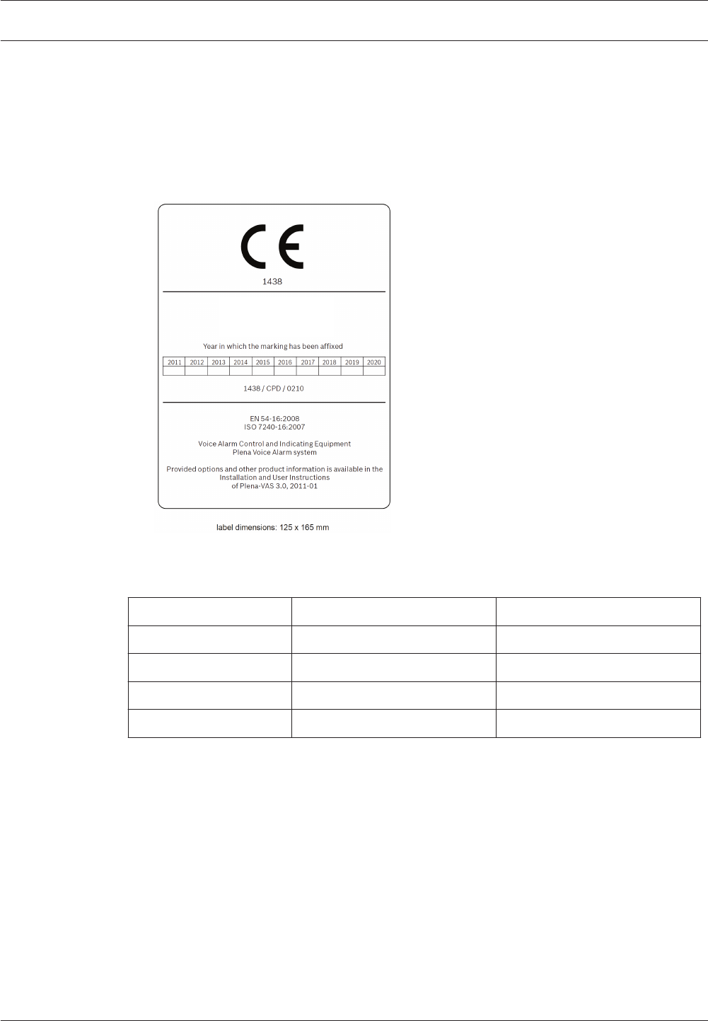
Checklist EN54‑16
Print and fill in the EN54‑16 checklist that could be download from the Installation and User
Instructions software directory from the Plena Voice Alarm System product related
information on www.boschsecurity.com, and affix the EN54‑16 label to the cabinet. The label
will look similar to this:
Bosch Security systems B.V.
Torenallee 49
5617 BA Eindhoven
The Netherlands
Figure 11.1: EN54‑16 label
Installer End-user
Name:
Signature:
Date:
Place:
Plena Appendices | en 139
Bosch Security Systems B.V. Installation and Operation manual 2013.07 | V2.0 |

4 General Requirements
Clause / Requirement Compliance Signature
4.1 General Plena is compliant.
4.1.1 If an optional function with
requirements is included in the VACIE,
then all the corresponding requirements
shall be met (see Annex B).
The following optional functions,
with requirements, are included in
Plena Voice Alarm System:
– Audible warning (7.3)
– Manual silencing of the voice
alarm condition (7.6.2)
– Manual reset of the voice alarm
condition (7.7.2)
– Voice alarm condition output
(7.9)
– Indication of faults related to
the transmission path to the CIE
(8.2.6)
– Indication of fault related to
voice alarm zones (8.2.7)
– Voice alarm manual control (10)
– Emergency microphone(s) (12)
– Microphone priority (12.2)
– Redundant power amplifiers
(13.14)
The following optional functions
with requirements are not included
in Plena Voice Alarm System:
– Delay(s) to entering the voice
alarm condition (7.4)
– Phased evacuation (7.5)
– Output to fire alarm devices
(7.8)
– Disabled condition (9)
– Interface to external control
device(s) (11)
4.1.2 If functions other than those
specified in this European Standard are
provided, they shall not jeopardize
compliance with any requirements of
this European Standard
4.2 Combined VACIE and CIE
When the VACIE and CIE are combined
they may share common indications,
manual controls and outputs (see
Annex F). In this case, the following
shall apply:
This requirement is not applicable.
In Plena Voice Alarm System, the
Voice Alarm Control and Indicating
Equipment (VACIE) is not combined
with a fire alarm Control and
Indicating Equipment (CIE).
140 en | Appendices Plena
2013.07 | V2.0 | Installation and Operation manual Bosch Security Systems B.V.

Clause / Requirement Compliance Signature
a single fault in the CIE shall not
adversely affect the mandatory
functions of the VACIE;
b indication(s) and manual control(s)
of the voice alarm condition shall be
clearly identifiable, with the
exception of the optional audible
warning.
4.3 Power supply Plena Voice Alarm System is
compliant.
Power supply equipment, external or
included in the VACIE, shall comply
with the requirements of EN 54‑4.
It is the responsibility of the installer
to use power supplies and battery
charging equipment in accordance
with EN 54‑4.
The PLN‑24CH12 is compliant to
EN54‑4.
NOTE - The power supply may be
shared with that of the fire detection
and fire alarm system.
The power supply may be shared
with that of a fire detection system,
but when operated with a battery a
new capacity calculation is required.
5 General requirements for indications
Clause / Requirement Compliance Signature
5.1 Display and functional conditions Plena Voice Alarm System is
compliant.
5.1.1 The VACIE shall be capable of
unambiguously indicating the following
functional conditions, as described in
Clauses 6 to 9:
– quiescent condition;
– voice alarm condition;
– fault warning condition;
– disablement condition (option with
requirements)
See Clauses 6 to 9.
Plena Voice Alarm System does not
have a disablement function.
5.1.2 The VACIE shall be capable of
being simultaneously in any
combination of the following functional
conditions on different voice alarm
zones:
The Plena Voice Alarm System is
capable of being simultaneously in
the voice alarm condition and in the
fault warning condition.
Plena Appendices | en 141
Bosch Security Systems B.V. Installation and Operation manual 2013.07 | V2.0 |

Clause / Requirement Compliance Signature
– voice alarm condition; The voice alarm condition is
indicated on each call station
(system status LED), remote control
or fireman’s panel and on the display
of the controller This system wide
indication can be combined with the
indication of the fault warning
condition: the controller gives an
audible warning on EMG condition
that has priority over the audible
fault signal. EMG condition is
indicated by a red LED, faults by
corresponding yellow LEDs,
therefore both conditions can be
indicated simultaneously.
– fault warning condition; The fault warning condition is
indicated on each call station
(system status LED), remote control
or fireman’s panel and on the display
of the controller (faults menu). This
system wide indication can be
combined with the indication of the
voice alarm condition The display of
the controller can indicate both the
voice alarm condition and the fault
warning.
– disablement condition (option with
requirements).
The optional disablement condition
is not implemented in Plena Voice
Alarm System.
5.2 Indication display Plena Voice Alarm System is
compliant.
All mandatory indications shall be
clearly identifiable, except where
otherwise specified in this European
Standard.
The Plena Voice Alarm System uses
the following color coding for
indications throughout the system:
– Green: system ok
– Red: system/zone in voice alarm
condition
– Yellow: system in fault warning
condition
5.3 Indication on alphanumeric
displays
Not applicable.
142 en | Appendices Plena
2013.07 | V2.0 | Installation and Operation manual Bosch Security Systems B.V.

Clause / Requirement Compliance Signature
Where an alphanumeric display is used
to display indications relating to
different functional conditions these
may be displayed at the same time.
However, for each functional condition
there shall be only one window, in
which all of the information relating to
that functional condition is grouped.
The front panel of the controller and
remote control panels have a field
with LEDs that have specific fault
assigned to them. Each zone has a
separate LED to signal a fault in that
zone.
If a zone on a router is in fault
condition. The main controller will
signal a router fault and the router
will indicate which zone.
The logging application delivered
with the Plena Voice Alarm System
offers a graphical user interface for
viewing events (Logging Viewer).
5.4 Indication of the supply of power Plena Voice Alarm System is
compliant.
5.4.1 A visible indication shall be given
by means of a separate discrete light-
emitting indicator while the VACIE is
supplied with power.
Each Plena Voice Alarm System
component has a dedicated power
LED.
5.4.2 Where the VACIE is distributed in
more than one cabinet, an indication of
supply of power to each distributed
cabinet shall be given at that point.
The Plena Voice Alarm System can
be distributed in more than one
cabinet, depending on the
installation of the system. Many
system components can be mounted
in a 19’’ rack. Each cabinet will
indicate supply of power
independently if the system is
distributed in more than one
cabinet.
5.5 Additional indications Plena Voice Alarm System is
compliant.
Where additional indications are
provided, they shall be clearly
identifiable and shall not override the
primary indication of the VACIE.
For LEDs with multiple indication
functions, all of the additional
indications are clearly identified (in
the Installation and User Instructions
of the Plena Voice Alarm System);
since the fault warning indication
and the voice alarm indication
always have precedence over the
additional indications, the primary
indications are not overridden.
Almost all LEDs indicate a single
function.
Plena Appendices | en 143
Bosch Security Systems B.V. Installation and Operation manual 2013.07 | V2.0 |

6 The quiescent condition
Clause / Requirement Compliance Signature
Any kind of system information may be
displayed during the quiescent
condition. However, no indications shall
be given which could be confused with
indications used in the
Plena Voice Alarm System is
compliant.
– voice alarm condition, If the Plena Voice Alarm System
enters the voice alarm condition,
controller, remote control panels
(including fireman’s panel), and each
call station will show a red system
status LED. In the quiescent
condition no red indicators are used
at all and the display of the
controller will never automatically
switch to the emergency menu.
– fault warning condition, If the Plena Voice Alarm System
enters the fault warning condition
each call station will show a yellow
fault LED. Yellow LEDs are solely
used for fault condition.
– disablement condition (option with
requirements).
The disablement condition is not
implemented in Plena Voice Alarm
System.
7 The voice alarm condition
Clause / Requirement Compliance Signature
7.1 Reception and processing of fire
signals
Plena Voice Alarm System is
compliant.
7.1.1 The VACIE shall be capable of
receiving and processing alarm signals
from the CIE or from manual control on
the VACIE or both, and causing the
appropriate voice alarm outputs to be
activated within 3 s or on expiry of any
delay period (see 7.4).
Alarm signals from the CIE can be
received from input contacts and the
Open Interface. Manual control is
possible via the controls and input
contacts. Note the call stations are
not part of the voice alarm function
and are disabled in the alarm
condition.
144 en | Appendices Plena
2013.07 | V2.0 | Installation and Operation manual Bosch Security Systems B.V.

Clause / Requirement Compliance Signature
NOTE - See Annex E for additional
information relating to the interface
between the VACIE and the CIE.
If input contacts are used for
connection of the CIE to the Plena
Voice Alarm System then the input
contacts can be monitored for short
circuit and open line. If the Open
Interface is used for connection of
the CIE to the VACIE, the
communication is monitored using
keep-alive messaging.
7.1.2 The mandatory indications and or
outputs shall not be falsified by multiple
alarm signals received simultaneously
from the CIE and/or manual controls.
The Plena Voice Alarm System offers
one alarm priority.
7.1.3 Where the VACIE and CIE are in
separate cabinets, failure of the
transmission path between the CIE and
the VACIE shall not result in any loss of
control or any change of state of the
VACIE.
The Plena Voice Alarm System is an
autonomous subsystem that can
operate without connection to the
CIE. The effect of the failure of the
transmission path between the CIE
and the Plena Voice Alarm System is
limited to fault reporting and losing
interaction between the CIE and the
Plena Voice Alarm System.
The system must be configured
correctly for this.
7.2 Indication of the voice alarm
condition
Plena Voice Alarm System is
compliant.
7.2.1 The presence of a voice alarm
condition shall be indicated on the
VACIE, without prior manual
intervention, by:
a a visible indication by means of a
separate discrete light emitting
indicator (the General Voice Alarm
Activated indicator);
A voice alarm condition is indicated
on the Plena Voice Alarm System by:
– A red indicator on all call
stations (the system status
LED).
– A textual indicator on the
controller display.
– A red indicator on the
controller.
b a visible indication for each
activated voice alarm zone where
manual controls are provided (see
10.2);
The controller and routers have a
separate LED per zone to indicate
activation of all zones.
Plena Appendices | en 145
Bosch Security Systems B.V. Installation and Operation manual 2013.07 | V2.0 |

Clause / Requirement Compliance Signature
NOTE - This may be by means of
separate discrete indicators or an
alphanumeric display as specified in
13.8.
c an optional audible indication, as
specified in 7.3.
The controller and remote control
panels (including fireman’s panel),
have a built-in sounder.
7.2.2 The audible warning shall be
capable of being silenced at access
level 1 or 2.
The sounder (see 7.2.1.c) can be
silenced by acknowledging the voice
alarm condition. The voice alarm
condition can be acknowledged by
means of an input contact, manual
operation at the controller or remote
control panels or via the Open
Interface.
7.3 Audible warning (option with
requirements)
An audible warning of the voice alarm
condition might be the same as that for
the fault warning condition. If they are
different, the voice alarm condition
warning shall have priority.
The voice alarm condition is
indicated by an audible warning on
EMG condition that has priority over
the audible fault signal. The EMG
condition is indicated by an
intermittent tone, the fault condition
by a continuous tone.
7.4 Delays to entering the voice alarm
condition (option with requirements)
The VACIE may be provided with a
facility to introduce a delay before
entering the voice alarm condition. In
this case:
Since the Plena Voice Alarm System
does not process the fire sensors,
this functionality is better handled
by the device managing the fire
sensors (the CIE). The Plena Voice
Alarm System itself does not
implement this requirement.
a the operation of the delay shall be
selectable at access level 3;
b the operation of the delay shall be in
increments not exceeding 1 min up
to a maximum of 10 min;
c the delay to one output signal shall
not affect the delay to other outputs;
d it shall be possible to override the
delay by a manual operation at
access level 1;
146 en | Appendices Plena
2013.07 | V2.0 | Installation and Operation manual Bosch Security Systems B.V.

Clause / Requirement Compliance Signature
e there shall be provision to switch on
and switch off delays by means of a
manual operation at access level 2
(see Annex A for information on
access levels);
f there may be provision to
automatically switch on and/or
switch off delays by means of a
programmable timer which shall be
configurable at access level 3;
g a separate discrete light emitting
indicator and/or a field on the
alphanumeric display shall be visible
when a fire signal is received and the
delay activated. This indication shall
be suppressed when the VACIE
enters the voice alarm condition.
7.5 Phased evacuation (option with
requirements)
Plena Voice Alarm System does not
accommodate phased evacuation.
The VACIE may have a provision to
phase the warning signals to the
emergency loudspeaker zones. The
facility shall be configurable at access
level 3. There may be provision to
switch on and switch off the phased
evacuation sequence by means of a
manual operation at access level 2 (see
Annex A for information on access
levels).
7.6 Silencing of the voice alarm
condition
Plena Voice Alarm System is
compliant.
7.6.1 Silencing of the voice alarm
condition from the CIE
7.6.1.1 Where the voice alarm condition
has been triggered from the CIE, the
VACIE shall respond appropriately to a
silence instruction from the CIE.
Voice alarm calls triggered from the
CIE can also be stopped from the
CIE. To reset the voice alarm
condition an Acknowledge
Emergency is possible for CIE and
on the front panels of the controller
and remote control panels.
Plena Appendices | en 147
Bosch Security Systems B.V. Installation and Operation manual 2013.07 | V2.0 |

Clause / Requirement Compliance Signature
7.6.1.2 The silencing procedure may
allow for the completion of messages in
the process of being broadcast.
If a voice alarm call is activated from
the contacts it is configurable
whether or not to stop or finish the
message. If the alarm condition is
reset from the front panel or the call
is aborted from the front panel of
the controller and remote control
panels, the message is topped
immediately.
7.6.2 Manual silencing of the voice
alarm condition (option with
requirements)
7.6.2.1 It shall be possible to manually
silence the voice alarm message from
the VACIE at access level 2.
Plena Voice Alarm System offers the
possibility to stop voice alarm calls
by de-activating (or re-activating) the
contact or key that started the call,
or. By using the front panel key on
the controller or remote control
panels, the messages can be routed
differently, or overruled.
7.6.2.2 Following silencing, it shall be
possible to re-activate the voice alarm
message at access level 2.
Voice alarm call can be re-activated
by starting that call again from a
contact, routing it to the zone(s)
again.
7.7 Reset of the voice alarm condition Plena Voice Alarm System is
compliant.
7.7.1 Reset of the voice alarm condition
from the CIE
Where the voice alarm condition has
been triggered from the CIE, the VACIE
shall respond appropriately to a reset
instruction from the CIE.
See 7.6.1.1.
7.7.2 Manual reset of the voice alarm
condition (option with requirements)
7.7.2.1 It shall be possible to reset the
voice alarm condition from the VACIE at
access level 2 by means of a separate
manual control. This control shall be
used only for reset and may be the
same as that used for reset from the
fault warning condition.
To reset the voice alarm condition an
Acknowledge Emergency and Reset
Emergency action is required. Plena
Voice Alarm System has dedicated
acknowledge and reset buttons on
the front panel of the controller and
remote controls.
148 en | Appendices Plena
2013.07 | V2.0 | Installation and Operation manual Bosch Security Systems B.V.

Clause / Requirement Compliance Signature
7.7.2.2 Following a reset operation, the
indication of the correct functional
condition corresponding to any received
signals shall either remain or be re-
established within 20 s.
After a reset operation, the Plena
Voice Alarm System will immediately
indicate the functional condition it is
currently in. It will also immediately
(<<1 s) respond to received signals
that will bring it into another
functional condition.
7.8 Output to fire alarm devices
(option with requirements)
This option is not supported by the
Plena Voice Alarm System.
In addition to the voice alarm outputs
the VACIE may have provision for the
automatic transmission of fire alarm
signals to fire alarm devices such as
beacons and vibrating devices. In this
case, the following shall apply:
a it shall be possible to de-activate the
fire alarm devices at access level 2;
b following de-activation, it shall be
possible to re-activate the fire alarm
devices at access level 2;
c the fire alarm devices shall not be
de-activated automatically;
d it shall be possible to configure the
VACIE at access level 3 to
automatically reactivate the fire
alarm devices if an alarm is reported
in an other zone.
7.9 Voice alarm condition output
(option with requirements)
Plena Voice Alarm System is
compliant.
The VACIE may have provision for
transmitting a signal that is in the voice
alarm condition. In this case, it shall
activate the output only in the voice
alarm condition.
The Plena Voice Alarm System
transmits a signal that it is in the
voice alarm condition via the Open
Interface, and via the status contact.
Plena Appendices | en 149
Bosch Security Systems B.V. Installation and Operation manual 2013.07 | V2.0 |

8 Fault warning condition
Clause / Requirement Compliance Signature
8.1 Reception and processing of fault
signals
Plena Voice Alarm System is
compliant.
8.1.1 The VACIE shall enter the fault
warning condition when signals are
received which, after any necessary
processing, are interpreted as a fault.
When the Plena Voice Alarm
System receives a supervision fault
signal (i.e. detects a fault in the
system), the fault warning
condition is entered until this state
is explicitly reset.
8.1.2 The VACIE shall be capable of
simultaneously recognizing all of the
faults specified in 8.2 and, if provided, in
8.3 unless this is prevented by:
– the presence of an alarm output signal
on the same voice alarm zone, and/or
All Plena Voice Alarm System faults
are handled (acknowledged and
reset) collectively. The faults are
indicated individually, if a contact
is configured as fault input, it may
indicate a fault in a zone groups or
individual zones, responsibility f
the installer.
– the disablement of the corresponding
voice alarm zone or function, and/or
Optional disablement of voice
alarm zones or functions is not
implemented in Plena Voice Alarm
System.
8.1.3 The VACIE shall enter the fault
warning condition within 100 s of the
occurrence of any fault, or the reception
of a fault signal or within another time as
specified in this European Standard or in
other parts of EN 54.
The Plena Voice Alarm System
recognizes and reports all faults
within 100 seconds.
8.2 Indication of faults in specified
functions
Plena Voice Alarm System is
compliant.
8.2.1 The presence of faults in specified
functions shall be indicated on the VACIE
without prior manual intervention. The
fault warning condition is established
when the following are present:
150 en | Appendices Plena
2013.07 | V2.0 | Installation and Operation manual Bosch Security Systems B.V.

Clause / Requirement Compliance Signature
a a visible indication by means of a
separate light emitting indicator (the
general fault warning indicator);
The Plena Voice Alarm System
provides a visible indication when
it is in the fault warning condition
via the fault LEDs of the of the call
stations, output contacts, and
front panels of controller, routers
and remote control panels.
Additionally the is a fixed fault
output contact on the controller.
b a visible indication for each
recognized fault as specified in 8.2.4,
and 8.2.5, 8.2.6, 8.2.7, if provided,
and 8.3;
The Plena Voice Alarm System
offers two ways of visual indication
of individual faults: via the front
panel of the controller, router, and
remote control panels and via the
Plena Voice Alarm System logging
application.
c an audible indication, as specified in
8.4.
The Plena Voice Alarm System
provides an audible fault indication
from the controller and remote
control panels.
8.2.2 If the indication is by means of
separate light-emitting indicators, these
may be the same as those to indicate
disablement of the corresponding alarm
zones or functions.
The optional function ‘disablement’
is not implemented in Plena Voice
Alarm System.
8.2.3 If the indication is on an
alphanumeric display, which cannot
simultaneously indicate all of the faults
because of its limited capacity, at least
the following shall apply:
a the presence of fault indications
which have been suppressed shall be
indicated;
Plena Voice Alarm System does not
have an alphanumeric display.
b suppressed fault indications shall be
capable of being displayed by means
of a manual operation at access level
1 or 2 which interrogates only fault
indications.
8.2.4 The following faults shall be
indicated by means of separate light
emitting indicators and/or an
alphanumeric display:
Plena Voice Alarm System is
compliant.
Plena Appendices | en 151
Bosch Security Systems B.V. Installation and Operation manual 2013.07 | V2.0 |

Clause / Requirement Compliance Signature
a an indication at least common to any
power supply fault resulting from:
The mains and backup power of all
Plena Voice Alarm System
elements are supervised
individually, depending on
configuration. The controller and
routers monitor the power sources
on a system level.
– a short circuit or an interruption in
a transmission path to a power
supply (item L of Figure 1 of
EN 54-1), where the power supply
is contained in a different cabinet
from that of the VACIE, and
– the power supply faults as
specified in EN 54-4;
b an indication at least common to any
earth fault of less than 50 kW is
capable of affecting a mandatory
function, and which is not otherwise
indicated as a fault of a supervised
function;
All 100V lines of the Plena Voice
Alarm System are supervised
individually for earth faults (i.e.
connections to earth with a
leakage resistance of less than 50 k
Ohm).
c an indication of the rupture of any
fuse within the VACIE, or the
operation of any protective device
within the VACIE which is capable of
affecting a mandatory function in the
fire alarm condition;
Every rupture of a fuse or the
operation of a protected device
that affects a mandatory function
will result in a fault since the
mandatory functions are
supervised. The reported fault is as
close to the located defect as
possible. E.g. a mains related fault
is reported as a mains fault and an
amplifier defect is reported as
defect for that amplifier.
d an indication of any short circuit or
interruption, at least common to all
transmission paths between parts of
the VACIE contained in more than one
cabinet, which is capable of affecting
a mandatory function and which is not
otherwise indicated as a fault of a
supervised function.
All transmission paths of the Plena
Voice Alarm System are
supervised.
All control input contacts of the
Plena Voice Alarm System can be
supervised for shorts and
interruptions.
Analog audio connections to
external parties can be supervised
by pilot tone supervision.
152 en | Appendices Plena
2013.07 | V2.0 | Installation and Operation manual Bosch Security Systems B.V.

Clause / Requirement Compliance Signature
These indications may be suppressed
during the fire alarm condition.
Plena Voice Alarm System fault
indicators are not suppressed.
There are separate indicators for
fault and voice alarm conditions.
The only exception is the audible
indicator.
8.2.5 The following faults shall be
indicated at least by means of the general
fault warning indicator:
a any short-circuit or interruption in a
voice alarm transmission path
between parts of the VACIE contained
in more than one cabinet even where
the fault does not affect a mandatory
function;
All transmission paths of the Plena
Voice Alarm System are
supervised.
When the Plena Voice Alarm
System is used in a redundant loop
configuration, the loss of the
redundant path is reported.
All control input contacts of the
Plena Voice Alarm System can be
supervised for shorts and
interruptions.
Analog audio connections to
external parties can be supervised
by pilot tone supervision.
b any short-circuit or interruption in the
voice alarm transmission path to the
emergency microphone capsule, if
provided;
The capsule of the Plena Voice
Alarm System emergency
microphone can be supervised for
both short-circuit and interruption.
This is configurable.
c any short-circuit or interruption in the
voice alarm transmission path
between the VACIE and loudspeakers
even where the fault does not affect
the operation of loudspeakers.
The loudspeaker lines of the Plena
Voice Alarm System can be
supervised.
Plena Appendices | en 153
Bosch Security Systems B.V. Installation and Operation manual 2013.07 | V2.0 |

Clause / Requirement Compliance Signature
d any short-circuit or interruption in the
transmission path between the VACIE
and fire alarm devices when used (see
7.8).
The Plena Voice Alarm System
does not offer this functionality
directly: control inputs are
supervised, but control outputs are
voltage free relay contacts. It is the
responsibility of the installer to
create a feedback signal
(corresponding to the transmission
path status between the Plena
Voice Alarm System and the fire
alarm device) to a supervised input
contact of the Plena Voice Alarm
System.
e failure of any power amplifier. All Plena Voice Alarm System
power amplifiers are supervised for
overload, overheating, short-
circuit, ground short and amplifier
defect.
8.2.6 Indication of faults related to the
transmission path to the CIE (option with
requirements)
The VACIE may have provision for an
indication of faults related to the
transmission path to the CIE. In this case,
the short-circuit or interruption of the
transmission path to the CIE shall be
indicated by means of a separate light
emitting indicator and/or an
alphanumeric display.
Plena Voice Alarm System is
compliant.
All input contacts of the Plena
Voice Alarm System can be
supervised for short and
interruption.
Open Interface connections are
supervised through keep-alive
messaging.
Faults related to the transmission
path to the CIE are therefore
individually reported and can be
inspected using the front panel of
the controller or the logging
application. The faults are also
reported through the general fault
warning indication.
8.2.7 Indication of faults related to voice
alarm zones (option with requirements)
154 en | Appendices Plena
2013.07 | V2.0 | Installation and Operation manual Bosch Security Systems B.V.

Clause / Requirement Compliance Signature
The VACIE may have provision for an
indication of faults related to voice alarm
zones. In this case the short-circuit or
interruption of a voice alarm transmission
path between the VACIE and the
loudspeakers in that zone shall be
indicated by means of a separate light
emitting indicator per zone and/or an
alphanumeric display.
Plena Voice Alarm System is
compliant.
Faults that occur in the Plena Voice
Alarm System are reported per
defective zone or monitored
function.
8.3 System fault Plena Voice Alarm System is
compliant.
A system fault is a fault as specified in
14.4 Program monitoring (see also Annex
C)or 14.6 Monitoring of memory contents
in the case of software controlled VACIE.
A system fault may prevent requirements
of this European Standard, other than
those specified below, from being
fulfilled. In the event of a system fault at
least the following shall apply:
a a system fault shall be visibly
indicated by means of the general
fault warning indicator and a separate
light emitting indicator on the VACIE.
These indications shall not be
suppressed by any other functional
condition of the VACIE and shall
remain until a manual reset and/or
another manual operation at access
level 2 or 3;
System faults are individually
reported by the Plena Voice Alarm
System and can be inspected using
the front panel menu of the
controller or the logging
application.
Faults are also reported through a
general fault warning indicator,
connected to a control output.
Both the individual fault indicator
of each system fault and the
general fault warning indicator are
not suppressed by any other
functional condition of the Plena
Voice Alarm System.
Plena Appendices | en 155
Bosch Security Systems B.V. Installation and Operation manual 2013.07 | V2.0 |

Clause / Requirement Compliance Signature
b a system fault shall be audibly
indicated. This indication may be
capable of being silenced.
The controller and remote control
panels all have a monitor speaker
that is used as a sounder in case of
a fault.
The audible fault indicator can be
silenced by acknowledging all
faults via a button on the front
panel of the controller and remote
control panels. The control output
for the visible fault indicator is only
deactivated upon resolving and
resetting the fault condition.
8.4
Audible indication
Plena Voice Alarm System is
compliant.
8.4.1
The audible indication of faults required
in 8.2 shall be capable of being silenced
manually at access level 1 or 2 at the
VACIE. The same manual operation may
be used as for silencing the voice alarm
condition.
The audible fault indicator can be
silenced by acknowledging all
faults via a key or control input
that is configured as Fault
acknowledge key. Individual faults
can also be acknowledged from
the front panel menu of the
controller or via the Open
Interface.
8.4.2
The audible indication shall be silenced
automatically if the VACIE is automatically
reset from the fault warning condition.
Since the Plena Voice Alarm
System does not offer automatic
reset from the fault warning
condition this requirement does
not need to be implemented.
8.4.3
If previously silenced, the audible
indication shall resound for each newly
recognized fault.
After the audible indication has
been silenced (by acknowledging
all faults) the Plena Voice Alarm
System will resound the indication
upon occurrence of a new fault or
reoccurrence of a previously
resolved fault.
8.5 Reset of fault indications Plena Voice Alarm System is
compliant.
8.5.1 Indications of faults as required in
8.2 shall be capable of being reset
a automatically when faults are no
longer recognized, and/or
The Plena Voice Alarm System
does not offer automatic reset of
faults
156 en | Appendices Plena
2013.07 | V2.0 | Installation and Operation manual Bosch Security Systems B.V.

Clause / Requirement Compliance Signature
b by a manual operation at access
level 2.
Faults can be manually reset by
acknowledging and resetting them.
Acknowledging and/or resetting
faults individually (as they appear)
can be done via the front panel
menu of the Controller and via the
Open Interface. Acknowledging
and/or resetting will acknowledge/
reset all faults in one action, This
can be done via the front panel
button of the controller, remote
control panels or the Open
Interface.
8.5.2 Following reset, the indication of
the correct functional conditions
corresponding to any received signals
shall either remain or be re-established
within 20 s.
If faults are reset, all individual
faults that are not actually resolved
in the system are reported again
within 20 seconds. The sounder
will not resound. the system
checks reported fault first
immediately. If the faults are
resolved when the reset is done,
and the fault reappear shortly
afterward the sounder will
resound.
8.6 Transmission of the fault warning
condition
Plena Voice Alarm System is
compliant.
The VACIE shall have provision for
transmitting, by means of at least general
fault signal, all faults specified in 8. This
fault signal shall also be given if the
VACIE is de-energized.
The Plena Voice Alarm System
controller has a fixed fault output.
This relay output contact indicates
no fault when open (energized)
and indicates a fault when closed
(de-energized). If the Plena Voice
Alarm System is de-energized this
output contact is closed, therefore
the fault signal will also be given.
Plena Appendices | en 157
Bosch Security Systems B.V. Installation and Operation manual 2013.07 | V2.0 |

9 Disablement condition (option with requirements)
Clause / Requirement
Compliance Signature
9.1 General requirements Plena Voice Alarm System does not
support the disablement condition.
9.1.1 Disablements in accordance with
the requirements of 9.4 shall inhibit all
corresponding mandatory indications
and/or outputs but shall not prevent
other mandatory indications and/or
outputs.
9.1.2 The VACIE shall have provision to
independently disable and re-enable the
function specified in 9.4 by means of
manual operations at access level 2.
9.1.3 The VACIE shall be in the disabled
condition while a disablement in
accordance with the requirements of
9.4 exists.
9.1.4 Disablement and re-enablement
shall not be affected by a reset from the
voice alarm condition or from the fault
warning condition.
9.2 Indication of the disabled condition
The disabled condition shall be
indicated visibly, by means of
a a separate light emitting indicator
(the general disablement indicator),
and
b an indication for each disablement,
as specified in 9.3 and 9.4.
9.3 Indication of specific disablements
9.3.1 Disablements shall either be
indicated within 2 s of the completion
of the manual operation or, where a
disablement cannot be completed
within 2 s, it shall be indicated within 2
s that the disabling process is running.
9.3.2 The same light-emitting indicator
may be used as that for the indication
of the corresponding fault, although the
indication shall be distinguishable.
158 en | Appendices Plena
2013.07 | V2.0 | Installation and Operation manual Bosch Security Systems B.V.

Clause / Requirement
Compliance Signature
9.3.3 If the indication is on an
alphanumeric display, which cannot
simultaneously indicate all of the
disablements because of its limited
capacity, at least the following shall
apply:
a the presence of disablement
indications which have been
suppressed shall be indicated;
b suppressed disablement indications
shall be capable of being displayed
by means of a manual operation at
access level 1 or 2 which
interrogates only disablement
indications.
9.4 Disablements and their indication
Voice alarm zones may be capable of
being independently disabled and re-
enabled. In this case the disablements
shall be indicated by means of separate
light emitting indicators per zone
and/or an alphanumeric display. The
indications shall not be suppressed
during the voice alarm condition.
9.5 Transmission of the disablement
condition
The VACIE shall have provision for
transmitting, by means of a general
disablement signal, all disablement
conditions specified in this clause.
10 Voice alarm manual control (option with requirements)
Clause / Requirement Compliance Signature
10.1 General requirements Plena Voice Alarm System is
compliant.
The VACIE may have provision for
manually activating the voice alarm
output condition. If a voice alarm output
control facility is provided the following
shall apply:
Plena Appendices | en 159
Bosch Security Systems B.V. Installation and Operation manual 2013.07 | V2.0 |

Clause / Requirement Compliance Signature
a a manual control which causes a
voice alarm output condition to be
given shall only be accessible at
access level 2;
The Plena Voice Alarm System can
enter the voice alarm output
condition manually via controls on
the front panel of the controller and
remote control panels, via input
contacts, and the Open Interface, by
starting a call with a high enough
priority.
b it shall be possible to activate each
voice alarm zone individually and/or
in group(s) of voice alarm zones;
A voice alarm priority call can be
manually activated in one or more
individual zones or zone groups.
Zone selection is possible via the
front panels of the controller, router
and remote control panels. Or via
the Open Interface (e.g. using a PC
Call Station for graphical
representation of zones with mouse
or touch screen selection).
Zones can also be added to and
removed from a running voice
evacuation call using the front
panels of the controller, router and
remote control panels.
c the manual activation of a voice
alarm zone shall not prevent the
mandatory indications and outputs
to other voice alarm zones.
Plena Voice Alarm System has one
channel for broadcasting. To ensure
that a new emergency call does not
affect a running call, the priorities of
all calls have to be the same.
Message merging and alternate
broadcasting is supported
responsibility of the installer.
Plena Voice Alarm System will abort
lower priority emergency calls if a
call with higher priority is started.
Non emergency audio is always
stopped when entering the
emergency state.
10.2 Indication of the voice alarm
zones in an activated condition
Plena Voice Alarm System is
compliant.
The indication for the voice alarm
condition in the voice alarm zone(s)
associated with each manual control
shall be available without any manual
action and shall not be suppressed. This
indication shall be by means of
160 en | Appendices Plena
2013.07 | V2.0 | Installation and Operation manual Bosch Security Systems B.V.

Clause / Requirement Compliance Signature
a a separate light emitting indicator
(the General Voice Alarm Output
activated indicator), and
The voice alarm condition is
indicated on the Plena Voice Alarm
System in general by a red indicator
inside the EMG button on the
controller, routers and remote
control panels.
b a separate light emitting indicator
and/or alphanumeric display for
each voice alarm zone and/or an
indication for group(s) of voice
alarm zones.
The voice alarm condition is
indicated on the Plena Voice Alarm
System per zone by a red indicator
on the controller, routers and
remote control panels.
NOTE - These indicators may not
necessarily indicate which emergency
message is being broadcast in each
voice alarm zone.
10.3 Indication of the voice alarm
zones in fault condition
Plena Voice Alarm System is
compliant.
The indication for the fault condition
which would prevent the generation and
transmission of the voice alarm signal to
the voice alarm zone(s) associated with
each manual control shall be available
without any manual action and shall not
be suppressed. This indication shall be
by
a a separate light emitting indicator
(the general fault indicator), and
Plena Voice Alarm System does not
have a common fault indicator. A
light emitting device must be
connected to the general fault
output to achieve this.
b an indication for each voice alarm
zone and/or an indication for
defined group(s) of zones.
The Plena Voice Alarm System
provides a visible indication when it
is in the fault warning condition via
the fault LED of the corresponding
zone for loudspeaker line related
faults and key (mandatory)
monitored elements. A fault
indicator of an individual zone may
indicate more than one fault.
Common to those fault are that they
occur in the indicated zone (e.g.
loudspeaker line short circuit, open
connection, ground short of the
same zone).
Plena Appendices | en 161
Bosch Security Systems B.V. Installation and Operation manual 2013.07 | V2.0 |

Clause / Requirement Compliance Signature
10.4 Indication of the voice alarm
zones in disablement condition
The indication for the disablement
condition in the voice alarm zone(s)
associated with each manual control
shall be available without any manual
action and shall not be suppressed. This
indication shall be by
Plena Voice Alarm System does not
support the optional disablement
condition.
a a separate light emitting indicator
(the general disablement indicator),
and
b an indication for each voice alarm
zone and/or an indication for
defined group(s) of zones.
11 Interface to external control device(s) (option with the requirements)
Clause / Requirement Compliance Signature
The VACIE may have provision for
interfacing to external control device(s)
such as standardized user interfaces
required by local regulations. In this case,
the following shall apply:
Plena Voice Alarm System does not
support the Interface to external
control device(s) option.
a the interface shall allow only access
level 1 and 2 functions;
b the mandatory functions of the VACIE
shall not be overridden;
c any short-circuit, interruption or earth
fault in the transmission path to the
external device(s) shall
– not prevent the mandatory
function of the VACIE, and
– be indicated on the VACIE, at least
by means of the general fault
warning indicator.
NOTE - The external control devices
should comply with available local or
national standards.
162 en | Appendices Plena
2013.07 | V2.0 | Installation and Operation manual Bosch Security Systems B.V.

12 Emergency microphone(s) (option with requirements)
Clause / Requirement Compliance Signature
12.1 General Plena Voice Alarm System is
compliant.
The VACIE may have provision for
emergency microphone(s). In this
case the emergency microphone(s)
shall have
Plena Voice Alarm System offers
two types of emergency
microphones with microphone
supervision:
– the emergency microphone on
the controller;
– the emergency microphone on
the remote control panels.
a priority over all inputs, including
pre-recorded messages,
The priority can be configured of a
call station. The call stations
cannot start an emergency
message.
The trigger inputs can have
emergency priorities, but will
always be lower than the
emergency microphones.
The emergency microphone can
have different priority levels.
b an emergency microphone control
to open the microphone channel,
All emergency microphones have a
push to talk (PTT) button built in.
c an indication of any short circuit or
interruption in the voice alarm
transmission path to the
microphone,
The microphone of a emergency
microphones (capsule and wiring)
can be configured to be
supervised.
d where a pre-announcement
attention drawing signal is
provided, an indicator adjacent to
the microphone shall show when
the signal has finished and live
speech can commence, and
The voice alarm system has a built
in monitor speaker and LED
indications of a running emergency
call. Pressing the emergency
microphone will always override
the automated message.
Plena Appendices | en 163
Bosch Security Systems B.V. Installation and Operation manual 2013.07 | V2.0 |

Clause / Requirement Compliance Signature
e when the emergency microphone
control is operated, any audible
indication that might interfere with
the use of the microphone shall be
automatically muted.
The monitor speaker is muted
during the live speech phase. All
sounders are acknowledged by the
use of the emergency microphone.
Microphone and sounder are
always at the same location, front
panels of controller and remote
control panels.
Other sources of interference
should be minimized by proper
installation, e.g. keep HVAC
equipment and loudspeakers at a
distance from the microphone.
It is not possible to avoid
interference from closely mounted
loudspeakers receiving the call.
12.2 Microphone priority (option
with requirements)
Plena Voice Alarm System is
compliant.
12.2.1 Where more than one
emergency microphone can be
connected to the VACIE, the
emergency microphones shall be
configurable for priority at access
level 3 or access level 4.
Configuration of the emergency
microphones is performed via the
PC interface of the controller. This
PC program requires access level
3.
For emergency microphones 3
priority levels are available, for
each possible MEG microphone
location. Maximum three EMG
microphone is a system: controller
and maximum two remote control
panels.
12.2.2 Where more than one
emergency microphone is configured
at each priority level, only one
microphone shall be active at any one
time.
Microphones should be configured
for different priorities.
164 en | Appendices Plena
2013.07 | V2.0 | Installation and Operation manual Bosch Security Systems B.V.

13 Design requirements
Clause / Requirement Compliance Signature
13.1 General requirements and
manufacturer's declarations
Plena Voice Alarm System is
compliant.
13.1.1 The VACIE shall comply with the
design requirements of this clause, where
relevant to the technology used. Some
requirements can be verified by testing.
Others can only be verified by inspection
of the design and its accompanying
documentation because of the
impracticability of testing all of the
possible combinations of functions and of
establishing the long-term reliability of
the VACIE.
See the relevant clauses regarding
testing and documentation.
13.1.2 In order to assist the process of
design inspection, the manufacturer shall
declare the following in writing:
a that the design has been carried out in
accordance with a quality
management system which
incorporates a set of rules for the
design of all elements of the VACIE;
The Bosch Security Systems B.V.
development department
responsible for development/
maintenance of the Plena Voice
Alarm System works according its
own development process,
Standard Development Process or
SDP.
Rules for the design of all elements
of the Plena Voice Alarm System
can be found in the TPD
(document repository). In the SDP
repository all process descriptions,
process implementation
documents, templates, guidelines,
etc. of the development processes
can be found.
b that the components of the VACIE
have been selected for the intended
purpose and are expected to operate
within their specification when the
environmental conditions outside the
cabinet of the VACIE comply with
Class 3k5 of EN 60721-3-3:1995 +
A2:1997.
The Plena Voice Alarm System was
designed as a compliant voice
alarm system.
13.2 Documentation Plena Voice Alarm System is
compliant.
Plena Appendices | en 165
Bosch Security Systems B.V. Installation and Operation manual 2013.07 | V2.0 |

Clause / Requirement Compliance Signature
13.2.1 The manufacturer shall prepare
installation and user documentation
which shall be submitted to the testing
authority together with the VACIE. This
shall comprise at least the following:
The Plena Voice Alarm System
Installation and User Instructions
(IUI) are provided as multilingual
pdf‑files on
www.boschsecurity.com product
related information including the
software for installation and
configuration.
a a general description of the
equipment, including a list of
The IUI contains a general
description of the Plena Voice
Alarm System . It includes an
EN54‑16 checklist, containing a list
of supported optional functions.
It describes all Plena Voice Alarm
System functions related to
EN54-16 or otherwise.
1 the optional functions with
requirements of this European
Standard,
2 the functions relating to other
parts of EN 54, and
3 the ancillary functions not required
by this European Standard;
b technical specifications of the inputs
and outputs of the VACIE, sufficient to
permit an assessment of the
mechanical, electrical, and software
compatibility with other components
of the system (e.g. as described in
EN 54‑1), including where relevant
The inputs and outputs for audio
and control are described in the
IUI, including the technical data,
system functions, configuration
instructions, compliancy to
standards. This includes the
information as requested in 13.2.1
b) 1)..7).
The Open Interface is described in
the ‘Software manual of the voice
alarm system.
1 the power requirements for
recommended operation,
Power requirements are described
in the respective manuals.
2 the maximum number of voice
alarm zones,
This is described in the respective
manuals.
3 information concerning the
connection of emergency
microphones,
This is described in the respective
manuals.
4 the maximum and minimum
electrical ratings for each input
and output,
This is described in the respective
manuals.
166 en | Appendices Plena
2013.07 | V2.0 | Installation and Operation manual Bosch Security Systems B.V.

Clause / Requirement Compliance Signature
5 information on the communication
parameters employed on each
transmission path,
This is described in the respective
manuals.
6 recommended cable parameters
for each transmission path, and
This is described in the respective
manuals.
7 fuse ratings; Main fuse ratings are described.
c specified means to limit the
consequences of fault (see 13.5.2);
The IUI describes the following
means to limit the consequences
of fault:
– Switchover to spare (standby)
amplifiers
– Audio/control input
supervision
– Backup power supply
– Loudspeaker line supervision
– The ability of the emergency
microphone to make a ‘fail
safe’ call in case of a
controller defect
– A/B group wiring of
loudspeakers
d configuring and commissioning
instructions;
Configuring and commissioning
instructions are included in the
IUI/SCM (installation and user
instruction and software
configuration manual).
e operating instructions; Operating instructions are included
in the IUI.
f maintenance information. Maintenance information of the
Plena Voice Alarm System is
included in the IUI.
13.2.2 The manufacturer shall prepare
design documentation that shall be
submitted to the testing authority
together with the VACIE. This
documentation shall include drawings,
parts lists, block diagrams, circuit
diagrams and a functional description to
such an extent that compliance with this
European Standard may be checked and
that a general assessment of the
mechanical and electrical design is made
possible.
All of the mentioned design
documentation is available as TPD
for inspection by testing
authorities.
Plena Appendices | en 167
Bosch Security Systems B.V. Installation and Operation manual 2013.07 | V2.0 |

Clause / Requirement Compliance Signature
13.3 Mechanical design requirements Plena Voice Alarm System is
compliant.
13.3.1 The cabinet of the VACIE shall be
of robust construction consistent with
the method of installation recommended
in the documentation. It shall meet at
least classification IP30 of
EN 60529:1991+A1:2000.
The installer is responsible for
implementing this requirement for
19”-units, by means of using a
correct 19”- frame, meeting at
least classification IP30 of EN
60529:1991+A1:2000.
13.3.2 All interconnections and settings
inside the cabinet shall be accessible at
level 3.
If the installer ensures that the
physical access to the Plena Voice
Alarm System is restricted to
access level 3, all interconnections
and settings inside the cabinet
(e.g. interconnections between the
system elements) are accessible at
this access level.
13.3.3 The VACIE may be housed in more
than one cabinet. If the documentation
shows that the cabinets may be installed
in locations distributed within the
protected premises, then all of the
mandatory manual controls and
indicators shall be on one cabinet or on
cabinets declared to be only suitable for
mounting adjacent to each other.
The IUI shows that the Plena Voice
Alarm System cabinets may be
installed in locations distributed
within the premises. One
dedicated Plena Voice Alarm
System remote control panels with
extentions as needed, can then be
used for all of the mandatory
controls and indicators. The
installer is responsible for proper
installation in order to fulfill this
requirement.
13.3.4 All mandatory manual controls and
light emitting indicators shall be clearly
labeled to indicate their purpose. The
labels shall be legible at 0.8 m distance in
an ambient light intensity from 100 lux to
500 lux.
All indicators are clearly labeled.
For language other than English.
Permanent labels are available.
168 en | Appendices Plena
2013.07 | V2.0 | Installation and Operation manual Bosch Security Systems B.V.

Clause / Requirement Compliance Signature
13.3.5 The terminations for transmission
paths and the fuses shall be clearly
labeled.
All terminations for transmission
paths are clearly labeled on all of
the Plena Voice Alarm System
elements (near the relevant
connectors).
The mains fuse for each Plena
Voice Alarm System element that
has a mains connector is labeled
on the rear plate of the element.
The rest of the fuses are not easily
accessible (only during service),
therefore this requirement does
not apply to them.
13.4 Electrical and other design
requirements
Plena Voice Alarm System is
compliant.
13.4.1 The processing of signals shall give
the highest priority to the voice alarm
condition.
Calls within the Plena Voice Alarm
System have a configured priority.
In case of conflicting requirements,
system resources are assigned to
the calls in order of priority. Voice
alarm call must be configured with
a high priority. All secondary
functions of the system are pre-
configured to stop in case calls
above emergency priority are
present; this includes calls below
the emergency priority.
13.4.2 Transitions between the main and
the standby power sources shall not
change any indications and/or the state
of any outputs, except those relating to
the power supplies.
Transition between the main and
standby power sources does not
change any of the indications
and/or state of any outputs of the
Plena Voice Alarm System, except
for the fault warning indication
(global and individual) in order to
report the failure of a power
source.
13.4.3 If the VACIE has provision for
disconnecting or adjusting the main or
the standby power source, this shall only
be possible at access level 3 or 4.
The Plena Voice Alarm System
elements that have a mains and
backup power supply offer
connectors for the main and
standby power source, a rear-
mounted voltage selector switch
and on/off switch. The installer is
responsible to ensure that these
items are only accessible at access
level 3 or 4.
Plena Appendices | en 169
Bosch Security Systems B.V. Installation and Operation manual 2013.07 | V2.0 |

Clause / Requirement Compliance Signature
13.5 Integrity of transmission paths Plena Voice Alarm System is
compliant.
170 en | Appendices Plena
2013.07 | V2.0 | Installation and Operation manual Bosch Security Systems B.V.

Clause / Requirement Compliance Signature
13.5.1 A fault in any voice alarm
transmission path between the VACIE and
other components of the voice alarm
system shall not affect the correct
functioning of the VACIE or of any other
voice alarm transmission path.
The Plena Voice Alarm System has
the following voice alarm
transmission paths between itself
and other parts of the voice alarm
system:
– transmission path between
CIE and Plena Voice Alarm
System via input contact or
Open Interface;
– transmission path between
Plena Voice Alarm System and
the loudspeaker(s).
If there is a fault in the
transmission path between the CIE
and an input contact of the Plena
Voice Alarm System, the
configured action of the input
contact will not be automatically
activated or de-activated. The
correct functioning of the Plena
Voice Alarm System or of any other
voice alarm transmission path is
therefore not affected. The fault
will be reported.
If there is a fault in the
transmission path between the CIE
and the Ethernet connection of the
controller of the Plena Voice Alarm
System (connection via Open
Interface), methods can no longer
be invoked by the CIE and no
events can be notified to the CIE.
However the fault will not affect
the correct functioning of the
Plena Voice Alarm System or any
other voice alarm transmission
path. The fault will just be
reported.
If there is a fault in the
transmission path between the
Plena Voice Alarm System, i.e. the
amplifier outputs and the
loudspeaker(s), the loudspeaker(s)
will not be able to produce the
intended audio signal. However the
fault will not affect the correct
functioning of the Plena Voice
Plena Appendices | en 171
Bosch Security Systems B.V. Installation and Operation manual 2013.07 | V2.0 |

Clause / Requirement Compliance Signature
Alarm System or any other voice
alarm transmission path. The fault
will just be reported.
13.5.2 Means shall be specified and
provided to ensure that a short circuit or
an interruption in the transmission path
to the loudspeaker(s) does not affect
more than one voice alarm zone for
longer than 100 s following the
occurrence of the fault.
Each audio output of the Plena
Voice Alarm System is only
assigned to one voice alarm zone
by definition. The IUI specifies this
clearly. Due to this, a short circuit
or interruption in the transmission
path to the loudspeaker(s) only
affects the voice alarm zone it was
assigned to.
Multiple zones may share one
amplifier channel. However, if
configured correctly (line
supervision switched on) the
routers will perform short circuit
isolation.
13.5.3 Means shall be specified and
provided to ensure that a single short
circuit or an interruption in any voice
alarm transmission path between
distributed cabinets of a VACIE does not
prevent the activation of a voice alarm
output condition to more than one voice
alarm zone for longer than 100 s
following the occurrence of the fault.
The voice alarm transmission path
between distributed cabinets of
the Plena Voice Alarm System is
achieved by means of the system
bus.
A single interruption or short
circuit in this bus will lead to loss
of functionality. To comply with
this article, all Plena Voice Alarm
System equipment must be housed
in one 19” rack.
172 en | Appendices Plena
2013.07 | V2.0 | Installation and Operation manual Bosch Security Systems B.V.

Clause / Requirement Compliance Signature
13.5.4 If the VACIE is designed to be used
with a power supply (item L of Figure 1 of
EN 54-1) contained in a separate cabinet,
then an interface shall be provided for at
least two voice alarm transmission paths
to the power supply, such that a short
circuit or an interruption in one does not
affect the other.
If a 19”-cabinet (rack) or adjacent
cabinets provide enough space for
the battery and/or charger, the
installer can install the complete
PSE (power supply equipment) as
referred in EN54-4 in one cabinet.
In that case this requirement is not
applicable.
In case the installer installs the
backup part of the PSE (battery
and charger) in a separate cabinet,
Plena Voice Alarm System provides
a separate (monitored) DC-backup
connection on the Plena Voice
Alarm System units. This implies
that a Plena Voice Alarm System
installation will always have two
separate voice alarm transmission
paths to the power supply: one for
mains and one for DC backup.
Both will not influence each other
(except for current drawn).
It is the responsibility of the
installer to let the installation
comply with this requirement.
13.6 Accessibility of indications and
controls
Plena Voice Alarm System is
compliant.
Plena Appendices | en 173
Bosch Security Systems B.V. Installation and Operation manual 2013.07 | V2.0 |

Clause / Requirement Compliance Signature
Four access levels shall be provided on
the VACIE, from access level 1 (most
accessible) to access level 4 (least
accessible). Manual controls at a given
access level shall not be accessible at a
lower access level.The following shall
apply:
The Plena Voice Alarm System
offers three types of user accounts
(with different access rights):
– User: user account type that
offers operational control of
the system; meant for
operational users of the Plena
Voice Alarm System;
– Installer: user account type
that offers operational
control, configuration and
diagnosis of the Plena Voice
Alarm System; meant for
installers and/or configurators
of the Plena Voice Alarm
System;
– Administrator: user account
type that offers full control of
the system including user
management, i.e. the ability to
add and delete user accounts.
Access level 1 is intended for
operational users of the Plena
Voice Alarm System. It provides
direct (unrestricted) operational
access to the Plena Voice Alarm
System via:
– Input contacts of system
components;
– The front panels of system
components;
– Remote control panels.
Access level 2 is intended for
operational users of the Plena
Voice Alarm System. Access level 2
needs to be secured by correct
installation and restriction access
to certain components.
– The open interface; access is
restricted by restriction
access to the PC.
174 en | Appendices Plena
2013.07 | V2.0 | Installation and Operation manual Bosch Security Systems B.V.

Clause / Requirement Compliance Signature
Access level 3 is intended for
installers and/or configurators of
the Plena Voice Alarm System. It
provides access for configuration
and diagnosis of the Plena Voice
Alarm System. This level of access
is offered through:
– The PC interface offered by
the configuration program of
the controller. A user name
and password need to be
provided to get access to this
interface.
– Physical access control by
means of installing the system
elements in a restricted
environment, such as placing
the 19”-units in a 19”-rack
with key lock. This type of
access can be used for
physical diagnosis of the
system, e.g. inspect
interconnections.
Access level 4 is intended for
maintenance personnel of the
Plena Voice Alarm System. It
provides software/firmware
upgrade of the Plena Voice Alarm
System components after logical
identification. This level of access
is offered through:
– The file transfer application of
the Plena Voice Alarm System
to transfer message sets to
the controller and upgrade the
system software. A password
is needed to be able to use
the File Transfer Application
and get access to the
controller.
a all mandatory indications shall be
visible at access level 1 without prior
manual intervention (e.g. the need to
open a door);
All indicators of the Plena Voice
Alarm System can be visible at
access level 1. The installer is
responsible for correct
implementation of this
requirement.
Plena Appendices | en 175
Bosch Security Systems B.V. Installation and Operation manual 2013.07 | V2.0 |

Clause / Requirement Compliance Signature
b manual controls at access level 1 shall
be accessible without special
procedures;
Manual controls of the Plena Voice
Alarm System at access level 1 are
accessible without special
procedures.
c indications and manual controls that
are mandatory at access level 1 shall
also be accessible at access level 2;
All Plena Voice Alarm System
indications (LEDs, equipment
connected to output contacts,
front panel display) and manual
controls (input contacts, call
station keys, front panel menus)
that are accessible at access level
1 will also be accessible at access
level 2. It may be needed to iinstal
the equipment in a 19”rack with a
glass door.
d entry to access level 2 shall be
restricted by a special procedure;
Physical access control by means
of installing the system elements in
a restricted environment, such as
placing (parts of the) 19”-units in a
19”-rack with key lock will be
needed.
e entry to access level 3 shall be
restricted by a special procedure,
differing from that for access level 2;
Entry to access level 3 is restricted
by a special procedure, see
clause13.6, access level 3
description for details. Correct
configuration and installation
(physical access control) will
ensure that the special procedure
differs from that of access level 2.
The installer should ensure that
the physical access procedure
differs from that of the physical
access procedure of access level 2,
if applicable.
f the entry to access level 4 shall be
restricted by special means which are
not part of the VACIE.
Entry to access level 4 is restricted
by means of having to use the File
Transfer Application (FTA), see
clause13.6, access level 4
description for details. This FTA is
only used for access level 4
functions and is therefore not part
of the daily operation/
configuration of the Plena Voice
Alarm System.
176 en | Appendices Plena
2013.07 | V2.0 | Installation and Operation manual Bosch Security Systems B.V.

Clause / Requirement Compliance Signature
NOTE - Further access levels are
permitted provided that they are distinct
from the access levels described in this
standard.
13.7 Indications by means of light-
emitting indicators
Plena Voice Alarm System is
compliant.
13.7.1 Mandatory indications from light
emitting indicators shall be visible in an
ambient light intensity up to 500 lux, at
any angle up to 22.5° from a line through
the indicator perpendicular to its
mounting surface
– at 3 m distance for the general
indications of functional condition,
– at 3 m distance for the indication of
the supply of power, and
– at 0.8 m distance for other
indications.
All of the light emitting indicators
of the Plena Voice Alarm System
fulfill this requirement. When
external light emitting indicators
are installed, such as LEDs
connected to fault contacts, or
light emitting indicators connected
to output contacts, the installer is
responsible for using indicators
that fulfill this requirement.
13.7.2 If flashing indications are used,
both the on period and the off period
shall be greater than or equal to 0.25 s,
and the frequencies of flash shall not be
less than
– 1 Hz for voice alarm indications, and
– 0.2 Hz for fault indications.
The fault indication does not flash;
it is steady on.
The voice alarm indication on the
equipment flashes with a
frequency of 1 Hz (on and off
period of 0.5 s).
13.7.3 If the same light emitting
indicators are used for the indication of
specific faults and disablements, fault
indications shall be flashing and
disablement indications shall be steady.
Disablement indication is not
available in the Plena Voice Alarm
System since Plena Voice Alarm
System does not support the
optional disablement condition.
13.8 Indications on alphanumeric
displays
Plena Voice Alarm System does not
have an alphanumeric display.
13.8.1 If an alphanumeric display consists
of elements or segments, the failure of
one of these shall not affect the
interpretation of the displayed
information.
13.8.2 If an alphanumeric display is used
to display mandatory indications, it shall
be clear and unambiguous.
Plena Appendices | en 177
Bosch Security Systems B.V. Installation and Operation manual 2013.07 | V2.0 |

Clause / Requirement Compliance Signature
13.8.3 Mandatory indications on an
alphanumeric display shall be legible for
at least one hour following the display of
a new indication of the voice alarm
condition and at least 5 minutes for fault
or disablement conditions, at 0,8 m
distance, in ambient light intensities from
5 to 500 lux, at any angle from the normal
to the plane of the display up to
– 22.5º when viewed from each side,
and
– 15º when viewed from above and
below.
13.9 Indication colors Plena Voice Alarm System is
compliant.
13.9.1 The colors of the general and
specific indications from light emitting
indicators shall be
a red for indications of voice alarms; The system status LED of Plena
Voice Alarm System call stations is
on (red) when the system is in the
voice alarm condition. The
indicators on the controller and
remote control panels are red. The
installer is responsible for
connecting a red light emitting
indicator to a ‘Visual EVAC
indicator’ output contact of the
Plena Voice Alarm System. All zone
indicators in emergency mode are
red.
178 en | Appendices Plena
2013.07 | V2.0 | Installation and Operation manual Bosch Security Systems B.V.

Clause / Requirement Compliance Signature
b yellow for indications of
– fault warnings, and
– disablements, or
The Fault LED of Plena Voice Alarm
System controller, routers and
remote control panels are yellow.
Additionally the call station
indicator is also yellow when the
system is in the fault warning
condition. The installer is
responsible for connecting a yellow
light emitting indicator to the
‘Visual fault indicator’ output
contact (or another output contact
configured for this function).
Disablement indication is not
available in the Plena Voice Alarm
System since Plena Voice Alarm
System does not support the
optional disablement condition.
c green for the indication that the VACIE
is supplied with power.
All light emitting indicators of the
Plena Voice Alarm System that
indicate power supply are green.
NOTE - Where voice alarm automatic
message status indicators are provided, it
may be advantageous to indicate the
difference between evacuation and alert
messages. In this case, red will be used
for emergency messages and yellow may
be used for alert messages.
13.9.2 The use of different colors is not
necessary for indications on
alphanumeric displays. However, if
different colors are used for different
indications, the colors used shall be as
specified in 13.9.1.
The Plena Voice Alarm System do
not use alphanumeric displays.
13.10 Audible indications Plena Voice Alarm System is
compliant.
Plena Appendices | en 179
Bosch Security Systems B.V. Installation and Operation manual 2013.07 | V2.0 |

Clause / Requirement Compliance Signature
13.10.1 Audible indicators shall be part of
the VACIE. The same device may be used
for voice alarm zone activated and fault
warning indications.
The monitor loudspeaker of the
Voice Alarm System is used for
both fault warning (continuous
tone) and emergency condition
(intermittent tone). If additional
sounders are desired, the installer
is responsible for connecting
sounders to output contacts
configured as ‘EVAC indicator’ or
‘fault indicator’. The installer may
decide to connect both the voice
alarm activated output contact as
well as the fault warning condition
activated output contact to the
same sounder.
13.10.2 The minimum sound pressure
level, measured under anechoic
conditions at a distance of 1 m, with any
access door(s) on the VACIE closed, shall
be
– 60 dBA for the voice alarm condition,
and
– 50 dBA for the fault warning
condition.
The installer is responsible for
either connecting a sounder that
complies with this clause outside
or inside the rack, or install the
system in a rack that is sufficiently
acoustic transparent. Advice is to
install a remote control panel, all
remote control panels and the
fireman’s panel have a monitor
speaker.
13.11 Indicator testing Plena Voice Alarm System is
compliant.
All mandatory visible and audible
indicators shall be testable by a manual
operation at access level 1 or 2.
Plena Voice Alarm System provides
an ‘Indicator test’ button. When
activated all indications the system
and all its connected routers are
switched on to visually check the
indicators. The remote control
panels have their own test button.
The indicators of that remote
control panel and connected
extensions will light up.
The installer is responsible for
making indicators that are
connected to control output
contacts testable.
13.12 Audio performance Plena Voice Alarm System is
compliant.
13.12.1 Output power
180 en | Appendices Plena
2013.07 | V2.0 | Installation and Operation manual Bosch Security Systems B.V.
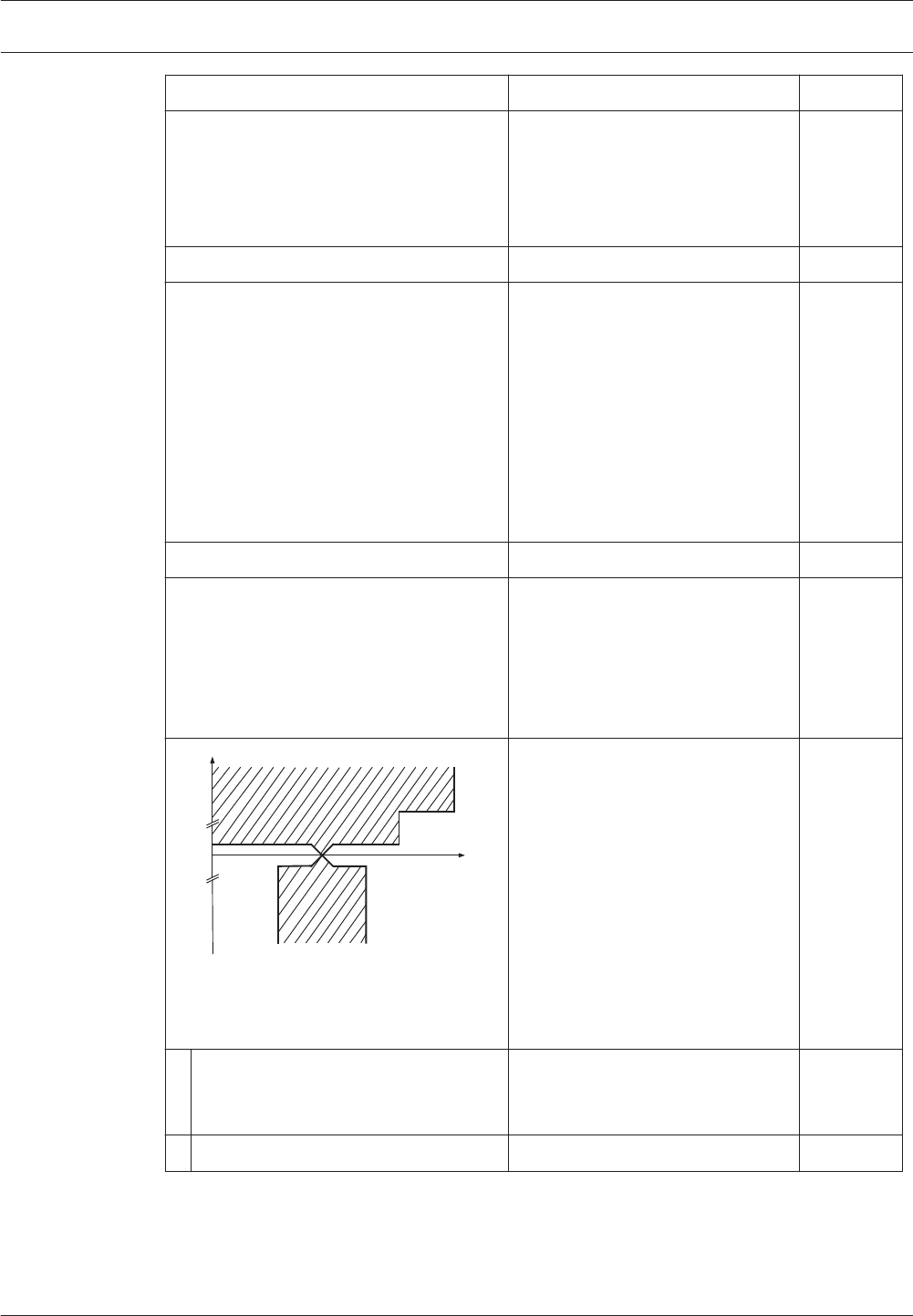
Clause / Requirement Compliance Signature
The VACIE output power shall be as
declared by the manufacturer.
The output power of the amplifier
elements of the Plena Voice Alarm
System (Power Amplifiers, Basic
Amplifiers) are specified in the
data sheets and in the IUI.
13.12.2 Signal-to-noise ratio
The VACIE shall have an A-weighted
signal-to-noise ratio of at least 45 dB (see
IEC 60268-1).
The A-weighted signal-to-noise
ratio of the Plena Voice Alarm
System amplifiers (Power
Amplifiers and Basic Amplifiers) is
specified in the data sheets and in
the IUI. The signal-to-noise ratio is
above 75 dB. The complete signal
chain from microphone to
loudspeaker is compliant to this
clause.
13.12.3 Frequency response
The frequency response of the VACIE
shall fit within the non-shaded area in
Figure 1 for sound sources without
microphone(s) (e.g. message store) and
Figure 2 for sound sources with
microphone(s).
2
4,0 8,0 20
-10
0,4
-20
-15
0
1
10
-1
0,125
15
20
1
1,0
VACIE frequency response limits without
microphone(s)
Key
The frequency response of all
Plena Voice Alarm System sound
paths that do not include
microphones is within the
specified limits of this clause.
1 relative output signal level, with
reference to 0 dB signal level
measured at 1 kHz (dB)
2 1/3 octave frequency band (Hz)
Plena Appendices | en 181
Bosch Security Systems B.V. Installation and Operation manual 2013.07 | V2.0 |

Clause / Requirement Compliance Signature
2
4,0 10
-10
0,5
-20
-15
0
5
10
-5
0,2
15
20
1
1,0
0,63
0,8 1,6
1,25
VACIE frequency response limits with
microphone(s)
Key
The frequency response of all
Plena Voice Alarm System sound
paths that include microphones is
within the specified limits of this
clause.
1 relative output signal level, with
reference to 0 dB signal level
measured at 1 kHz (dB)
2 1/3 octave frequency band (Hz)
NOTE - The frequency response limits
exclude loudspeakers.
NOTE - A bandwidth of 400 Hz to 4 kHz is
sufficient to achieve acceptable
intelligibility in some acoustic
environments. However, a higher
frequency limit may be necessary to
achieve acceptable intelligibility in more
difficult acoustic environments due, for
example, to the masking effect caused by
reverberation and/or ambient noise.
13.13 Message store(s) Plena Voice Alarm System is
compliant.
Pre-recorded messages shall be stored in
non-volatile memory that retains the
messages when all power sources are
removed.
The pre-recorded messages of the
Plena Voice Alarm System are
digitally stored on a Flash memory
in uncompressed format (linear
PCM, 16-bit, 44.1kHz). This card
retains the messages when all
power sources are removed.
NOTE - The use of tapes or magnetic or
optical data disks for the storage of
emergency messages is not acceptable at
the time of drafting this European
Standard (see Annex C)
13.14 Redundant power amplifiers
(option with requirements)
Plena Voice Alarm System is
compliant.
182 en | Appendices Plena
2013.07 | V2.0 | Installation and Operation manual Bosch Security Systems B.V.

Clause / Requirement Compliance Signature
13.14.1 The VACIE may have provision for
at least one spare power amplifier. In this
case:
The Plena Voice Alarm System has
a minimum of one main amplifier
and one call amplifier. It has a
maximum of one main amplifier per
router and one spare amplifier per
router (including the router built in
the controller). Each router of the
Plena Voice Alarm System has an
input for connecting a spare
amplifier channel. It also contains
switch-over relays to switch the
loudspeaker load from the original
amplifier output to the spare
amplifier output. A spare amplifier
channel assignment is configurable
to multiple routers (in single
channel mode).
a in the event of the failure of a power
amplifier, the faulty amplifier shall be
capable of being replaced
automatically with a spare amplifier
within 10 s of the fault being
detected;
After fault detection of an amplifier
all loudspeaker lines are switched
automatically to the spare amplifier
(if connected and configured)
within 10 s.
NOTE - This can be achieved, for
example, by switching or by permanently
connected parallel amplifiers.
b the spare power amplifier(s) shall
have at least the same functionality
and output power as the replaced
amplifier.
Each router of the Plena Voice
Alarm System has a spare amplifier
input. The installer is responsible
for proper installation and
configuration of the amplifiers to
match amplifier power and load.
Plena Voice Alarm System takes
care of input signal switching to
the spare amplifier channel. This
way the spare power amplifier(s)
will have the same functionality
and output power as the replaced
amplifier.
Plena Appendices | en 183
Bosch Security Systems B.V. Installation and Operation manual 2013.07 | V2.0 |

Clause / Requirement Compliance Signature
13.14.2 Every fault of an amplifier shall
be indicated by a general fault warning
indicator as specified in .2
All Plena Voice Alarm System
power amplifiers are supervised for
overload, overheating, short-
circuit, ground short and amplifier
defect. If any such fault is detected
it is indicated both by means of the
general fault warning indicator and
by means of an individual fault
LED.
13.14.3 Supervision of the spare
amplifier(s) shall be maintained during
the functional condition whilst the VACIE
is powered by either the mains or
standby power supplies.
The spare amplifiers are
continuously supervised,
supervision is identical to the main
(call) amplifier.
The supervision is active whilst the
Plena Voice Alarm System is
powered by either the mains or
standby power supplies.
Note: the spare amplifiers in the
Voice Alarm System are used as
background music amplifiers (if so
configured).
14 Additional design requirements for software controlled VACIE
Clause / Requirement Compliance Signature
14.1 General requirements and
manufacturer's declarations
Plena Voice Alarm System is
compliant.
In order to fulfill requirements of this
European Standard the VACIE may
contain elements which are controlled by
software. In this case, the VACIE shall
comply with the requirements of Clause
13 Design requirements and this clause
where relevant to the technology used.
The Plena Voice Alarm System is
centrally controlled by the
software running on the controller.
14.2 Software documentation Plena Voice Alarm System is
compliant.
14.2.1 The manufacturer shall prepare
documentation that gives an overview of
the software design, which shall be
submitted to the testing authority
together with the VACIE. This
documentation shall be in sufficient detail
for the design to be inspected for
compliance with this European Standard
and shall comprise at least the following:
The software design
documentation is available for
testing authorities. It is in
sufficient detail for the design to
be inspected for compliance.
184 en | Appendices Plena
2013.07 | V2.0 | Installation and Operation manual Bosch Security Systems B.V.

Clause / Requirement Compliance Signature
a functional description, using a clear
methodology appropriate to the
nature of the software, e.g. graphical
representations of the system design,
data flows and control flows andof the
main program flow, including:
Software design documents are
available and maintained.
1 a brief description of each module
and the tasks it performs,
Architecture documents are
available.
2 the way in which the modules
interact,
Architecture and design
documents are available.
3 the way in which the modules are
called, including any interrupt
processing, and
Architecture and design
documents are available.
4 the overall hierarchy of the
program;
Architecture documents are
available.
b a description of which areas of
memory are used for the various
purposes (e.g. the program, site
specific data and running data);
Memory usage is described in the
system architecture document.
c a description of how the software
interacts with the hardware of the
VACIE.
Hardware software interaction is
desribed in a set of Hardware-
Software Interface documentation.
Where dynamic memory management is
employed, a separation shall be
implemented between the program, site
specific data and running data and this
shall be described in connection with the
method of memory allocation.
The program is located in separate
Flash EPROMs that are reserved
for the program executable.
The message data is stored on a
separate Flash EPROMs.
14.2.2 The manufacturer shall prepare
and maintain detailed design
documentation. This need not be
submitted to the testing authority but
shall be available for inspection in a
manner which respects the
manufacturer's rights of confidentiality.
This documentation shall comprise at
least the following:
The software design documents
contain detailed design
documentation. Furthermore code
comments also contain detailed
design documentation.
a a description of each module of the
program, as it is implemented in the
source code of the program,
containing:
– the name of the module, and
– the identification of the
author(s);
The Plena Voice Alarm System
software component descriptions
(module descriptions) are available
from the software architecture
documents. These documents
contain the names of the
components.
Plena Appendices | en 185
Bosch Security Systems B.V. Installation and Operation manual 2013.07 | V2.0 |

Clause / Requirement Compliance Signature
b the source code listing, including all
global and local variables, constants
and labels used, and sufficient
comment for the program flow to be
recognized;
The source code can be obtained.
c details of any software tools used in
the preparation of the program (e.g.
high level design tools, compilers,
assemblers).
The list can be composed on
request and contains high level
design tools, compilers for various
processors, syntax validation tools,
build tools, test tools, performance
validation tools, version control
tools, and defect tracking tools.
14.3 Software design Plena Voice Alarm System is
compliant.
In order to ensure the reliability of the
VACIE the following requirements for
software design shall apply:
a the software shall have a modular
structure;
The modular structure of the Plena
Voice Alarm System software is
documented in the software
architecture documents.
b the design of the interfaces for
manually and automatically generated
data shall not permit invalid data to
cause an error in the program
execution;
The interfaces between the
modules and to external
components are well defined and
described in the design documents
and external interface documents
(Open Interface). Asserts are used
to validate inputs on component
boundaries.
c the software shall be designed to
avoid the occurrence of a deadlock in
the program flow.
Design guidelines are in place to
avoid deadlocks. Multi threading
within components is avoided
where feasible and components
have an input command queue for
safe decoupling of threads.
14.4 Program monitoring (see also
Annex C)
Plena Voice Alarm System is
compliant.
14.4.1 The execution of the program shall
be monitored as under 14.4.2 or 14.4.3. If
routines associated with the main
functions of the program are no longer
executed, either or both of the following
shall apply:
186 en | Appendices Plena
2013.07 | V2.0 | Installation and Operation manual Bosch Security Systems B.V.

Clause / Requirement Compliance Signature
a the VACIE shall indicate a system fault
(as in 8.3);
Upon activation of a watchdog, a
fault is reported after restart of the
failing component indicating the
failing unit and processor. A
system fault is indicated when
entering the fault condition.
b the VACIE shall enter the fault warning
condition and indicate faults of
affected supervised functions (as in
8.2.4, 8.2.5, 8.2.6 and 8.3), where only
these functions are affected.
Upon activation of a watchdog, a
fault is reported after restart of the
failing component indicating the
failing unit and processor.
14.4.2 If the program executes in one
processor, the execution of the routines
in 14.4.1, it shall be monitored by a
monitoring device as in 14.4.4.
All processors used in the Plena
Voice Alarm System are either
guarded by a hardware watchdog
or are monitored by a processor
that is guarded by a hardware
watchdog.
14.4.3 If the program executes in more
than one processor, the execution of the
routines in 14.4.1 shall be monitored in
each processor. A monitoring device as in
14.4.4 shall be associated with one or
more processors, and at least one such
processor shall monitor the functioning of
any processor not associated with such a
monitoring device.
All processors are either guarded
by a hardware watchdog or are
monitored by a processor that is
guarded by a hardware watchdog.
The controller is responsible for
monitoring all processors in the
system. Upon failure of one of the
processors, either due to a
watchdog failure or due to a
communication failure a fault is
generated. Failure of the controller
itself will cause the system fault
output contact to be de-energized
to indicate a system fault.
14.4.4 The monitoring device of 14.4.2
and 14.4.3 shall have a time-base
independent of that of the monitored
system. The functioning of the monitoring
device, and the signaling of a fault
warning, shall not be prevented by a
failure in the execution of the program of
the monitored system.
All processors are either guarded
by a hardware watchdog or are
monitored by a processor that is
guarded by a hardware watchdog.
Additionally the correct operation
of the main processor of all system
elements is validated by adding
execution checks on relevant
locations in the code. This to
assure that no important flow is
excluded from execution.
Plena Appendices | en 187
Bosch Security Systems B.V. Installation and Operation manual 2013.07 | V2.0 |

Clause / Requirement Compliance Signature
14.4.5 In the event of a system fault as
specified in 14.4.1 a) or 14.6, those parts
of the VACIE affected shall enter a safe
state not later than the indication of the
system fault. This safe state shall not
result in the false activation of mandatory
outputs.
Upon restart of a unit other than
the Controller, the unit will be
reinitialized and reordered to its
expected state.
14.5 The storage of programs and data
(see also Annex C)
Plena Voice Alarm System is
compliant.
14.5.1 All executable code and data
necessary to comply with this European
Standard shall be held in memory that is
capable of continuous, unmaintained,
reliable operation for a period of at least
10 years.
All Plena Voice Alarm System
programs (executable code and
data) are stored in Flash EEPROM.
14.5.2 For the program, the following
requirements shall apply:
a the program shall be held in non-
volatile memory, which can only be
written to at access level 4, and
Firmware (i.e. the program) can be
replaced using the File Transfer
Application. Using the File Transfer
Application requires access level 4.
b it shall be possible to identify the
version reference or references of the
program at access level 3. The version
reference or references shall be in
accordance with the documentation of
13.2.1.
The version of the firmware of the
units is visible on the units It is
noted on the rear of the unit
(access level 3).
14.5.3 For site-specific data, including
emergency message(s), the following
requirements shall apply:
a the alteration of site specific data
shall only be possible at access level 3
or 4;
Alteration of configuration can only
be done via the configuration
program or access to the units
from the rear. This includes the
File Transfer Application (message
sets). Getting access to the
configuration of the controller
requires access level 3. Using the
File Transfer Application requires
access level 4.
188 en | Appendices Plena
2013.07 | V2.0 | Installation and Operation manual Bosch Security Systems B.V.

Clause / Requirement Compliance Signature
b the alteration of site specific data
shall not affect the structure of the
program;
Configuration of the Plena Voice
Alarm System is implemented to
be data-driven and is not part of
the program executable. Also
transferring message sets to the
Plena Voice Alarm System is data-
driven and is not part of the
program executable. Therefore
alteration of the site specific data
does not affect the structure of the
program.
c if stored in read-write memory, there
shall be a mechanism which prevents
the memory being written to during
normal operation at access level 1 or
2, such that its contents are protected
during a failure in program execution;
Site specific data is stored in a
Flash EEPROM based file system.
Writing of data is only possible via
the password protected PC
program.
d It shall be possible to either read or
interrogate the site specific data at
access level 2 or 3, or the site specific
data shall be given a version reference
that shall be updated when each set
of alterations is carried out.
Site specific data can be viewed
and maintained from the
configuration (PC) program. Using
the configuration (PC) program
requires access level 3.
e If the site specific data has a version
reference, it shall be possible to
identify this at access level 2 or 3.
The site specific data of the Plena
Voice Alarm System does not have
a version reference.
14.6 Monitoring of memory contents Plena Voice Alarm System is
compliant.
The contents of the memories containing
the site specific data shall be
automatically checked at intervals not
exceeding 1 h. The checking device shall
signal a system fault if a corruption of the
memory contents is detected.
The message store is checked
every 100 s using checksum
validation. Upon detecting
corruption, a fault is reported
indicating a corrupt message store.
15 Marking
Clause / Requirement Compliance Signature
Plena Voice Alarm System is
compliant.
The VACIE shall be marked with the
following information, which shall be
legible at access level 1:
Plena Appendices | en 189
Bosch Security Systems B.V. Installation and Operation manual 2013.07 | V2.0 |

Clause / Requirement Compliance Signature
a the number of this European
Standard;
Marking the Plena Voice Alarm
System with the number of this
European standard (which is legible
at access level 1) is the
responsibility of the installer, since
the installer will have to install and
configure the system properly in
order to let the installation comply
with this standard.
b the name or trademark of the
manufacturer or supplier;
The name ‘Bosch ’ is visible on each
element of the Plena Voice Alarm
System. It is the responsibility of the
installer to ensure that this name is
legible at access level 1 for all
system elements.
c the type number or other
designation of the VACIE.
The type number of each unit of the
Plena Voice Alarm System is present
on the unit itself. The installer is
responsible for ensuring that this
type number is legible at access
level 1.
It shall be possible to identify a code or
number that identifies the production
period of the VACIE at access level 1 or
2 or 3.
The hardware version and
production data are visible on the
type number plate of each unit of
the Plena Voice Alarm System. The
installer is responsible for ensuring
that this type number plate is
identifiable at access level 1, 2 or 3.
Where Annex ZA.3 covers the same
requirements as this clause, the
requirements of this clause are met.
16 Tests
Clause / Requirement Compliance Signature
Test have been carried out during
certification of the Plena Voice Alarm
System.
190 en | Appendices Plena
2013.07 | V2.0 | Installation and Operation manual Bosch Security Systems B.V.

Bosch Security Systems B.V.
Torenallee 49
5617 BA Eindhoven
The Netherlands
www.boschsecurity.com
© Bosch Security Systems B.V., 2013
