Bosch VIDEOJET_decoder_8000_en Installation Manual (VIDEOJET Decoder 8000) VJD 8000 En US 22363072907
User Manual: Bosch Installation Manual (VIDEOJET decoder 8000) VIDEOJET decoder 8000
Open the PDF directly: View PDF ![]() .
.
Page Count: 28
VIDEOJET decoder 8000
VJD-8000 | VJD-8000-N
en Installation manual

VIDEOJET decoder 8000 Table of contents | en 3
Bosch Securtity Systems B.V. Installation manual 2016.03 | V2 | DOC
Table of contents
1Safety 5
1.1 Electric shock hazard 5
1.2 Installation and operation 5
1.3 Maintenance and repair 5
1.4 Firmware and software 6
2Short information 7
2.1 About this manual 7
2.2 Conventions in this manual 7
2.3 Intended use 7
2.4 EU Directives 7
2.5 Rating plate 7
3System overview 8
3.1 Parts included 8
3.2 Overview of functions 8
3.3 Connections, controls and displays 11
4Installation 12
4.1 Preparations 12
4.2 Mounting 12
5Connection 14
5.1 Sequence of connections 14
5.2 Connecting monitors 14
5.3 Establishing the network connection 14
5.4 Connecting audio 14
5.5 Connecting the power supply 14
5.6 Power on/power off 14
6Configuration 16
6.1 Setting up the decoder with Configuration Manager 16
6.1.1 Unit Access tab 16
6.1.2 Advanced tab 17
6.1.3 Network Access tab 17
6.2 Integrating the decoder into the video system 18
6.3 Configuring the decoder with Video Client 18
7Troubleshooting 19
7.1 Contact 19
7.2 General malfunctions 19
7.3 LEDs 19
8Maintenance 21
8.1 Updates 21
8.2 Repairs 21
9Decommissioning 22
9.1 Transfer 22
9.2 Disposal 22
10 Technical data 23
10.1 Electrical 23
10.2 Mechanical 23
10.3 Environmental conditions 23
10.4 Certifications and approvals 23
10.5 Standards 23


VIDEOJET decoder 8000 Safety | en 5
Bosch Securtity Systems B.V. Installation manual 2016.03 | V2 | DOC
1 Safety
Documentation and software for Bosch Security Systems products can be found in the
online product catalogue as follows:
4Open any browser > enter www.boschsecurity.com > select your region and your country
> start a search for your product > select the product in the search results to show the
existing files.
4Use the QR code on the Quick Installation Guide for direct access.
1.1 Electric shock hazard
– Never attempt to connect the unit to any power network other than the type for which it
is intended.
– Use only the power supply unit that is included.
– Connect the unit to an earthed mains socket-outlet.
– Never open the housing.
– Never open the housing of the power supply unit.
– If a fault occurs, disconnect the power supply unit from the power supply and from all
other units.
– Install the power supply and the unit only in a dry, weather-protected location.
– If safe operation of the unit cannot be ensured, remove it from service and secure it to
prevent unauthorized operation. In such cases, have the unit checked by Bosch Security
Systems.
Safe operation is no longer possible in the following cases:
– if there is visible damage to the unit or power cables,
– if the unit no longer operates correctly,
– if the unit has been exposed to rain or moisture,
– if foreign bodies have penetrated the unit,
– after long storage under adverse conditions, or
– after exposure to extreme stress in transit.
1.2 Installation and operation
– The relevant electrical engineering regulations and guidelines must be complied with at
all times during installation.
– Relevant knowledge of network technology is required to install the unit.
– Pluggable devices must have an easily accessible socket-outlet installed near the
equipment.
– Before installing or operating the unit, make sure you have read and understood the
relevant documentation. The documentation contains important safety instructions and
information about permitted uses.
– Perform only the installation and operation steps described in this manual. Any other
actions may lead to personal injury, damage to property or damage to the equipment.
1.3 Maintenance and repair
– Never open the housing of the unit. The unit does not contain any user-serviceable parts.
– Never open the housing of the power supply unit. The power supply unit does not contain
any user-serviceable parts.
– Ensure that all maintenance or repair work is carried out only by qualified personnel
(electrical engineers or network technology specialists). In case of doubt, contact your
dealer's technical service center.

6en | Safety VIDEOJET decoder 8000
2016.03 | V2 | DOC Installation manual Bosch Securtity Systems B.V.
1.4 Firmware and software
– VIDEOJET decoder8000 may only be operated with the installed firmware and software
products.
– It is not allowed to install additional firmware or software other than intended.
VIDEOJET decoder 8000 Short information | en 7
Bosch Securtity Systems B.V. Installation manual 2016.03 | V2 | DOC
2 Short information
2.1 About this manual
This manual is intended for persons responsible for the installation and operation of a
VIDEOJET decoder8000 unit. International, national and any regional electrical engineering
regulations must be followed at all times. Relevant knowledge of network technology is
required. The manual describes the installation of the unit.
2.2 Conventions in this manual
In this manual, the following symbols and notations are used to draw attention to special
situations:
!
Warning!
Use of this signal word and symbol indicates that failure to follow the safety instructions
described may endanger persons. It indicates a hazardous situation which, if not avoided,
could result in death or serious injury.
!
Caution!
Use of this signal word and symbol indicates that failure to follow the safety instructions
described may endanger persons. It indicates a hazardous situation which, if not avoided,
could result in minor or moderate injury.
Notice!
Use of this signal word and symbol indicates that failure to follow the safety instructions
described may cause damage to the unit or other equipment or may lead to data loss.
2.3 Intended use
The VIDEOJET decoder8000 video decoder receives and decodes video and audio signals over
data networks (Ethernet LAN, Internet). It displays video from Standard Definition (SD), High
Definition (HD), 4KUltra High Definition (UHD), and Megapixel (MP) cameras and encoders
using H.264 or MPEG‑4 encoding at up to 60frames per second over IP networks. The unit is
intended for use with CCTV systems. Other applications are not permitted.
In the event of questions concerning the use of the unit which are not answered in this
manual, please contact your sales partner or:
Bosch Sicherheitssysteme GmbH
Robert-Bosch-Ring 5
85630 Grasbrunn
Germany
www.boschsecurity.com
2.4 EU Directives
VIDEOJET decoder8000 complies with the requirements of EU Directives 89/336
(Electromagnetic Compatibility) and 73/23, amended by 93/68 (Low Voltage Directive).
2.5 Rating plate
For exact identification, the model name and serial number are inscribed on the bottom of the
housing. Please make a note of this information before installation, if necessary, so as to have
it to hand in case of questions or when ordering spare parts.

8en | System overview VIDEOJET decoder 8000
2016.03 | V2 | DOC Installation manual Bosch Securtity Systems B.V.
3 System overview
3.1 Parts included
– 1 VIDEOJET decoder8000, video decoder
– 1 international power supply unit with EU and US power cord
– 1 monitor mounting kit
– 1 Quick Installation Guide
– 1 Safety Hints
Notice!
Check that the delivery is complete and in perfect condition. Arrange for the unit to be
checked by Bosch Security Systems if you find any damage.
3.2 Overview of functions
Video decoder
VIDEOJETdecoder8000 displays video from Standard Definition (SD), High Definition (HD),
4KUltra High Definition (UHD), and Megapixel (MP) cameras and encoders using H.264 or
MPEG‑4 encoding at up to 60frames per second over IP networks.
It can flawlessly decode two 4Kp30 streams at 20Mbps, or six 1080p30 streams, or eight
H.264 720p60 streams, or twelve H.264 720p30 streams, all at 10Mbps. Alternatively, it can
simultaneously decode 30H.264 SD streams at up to 6Mbps from fast-moving AUTODOME
cameras with the highest clarity. When H.264 SD streams at up to 2.5Mbps from medium
activity scenes are connected, up to 60streams can be displayed.
VIDEOJETdecoder8000 can drive two 4KUHD displays directly, each with an independently
configurable screen layout, and so is ideally suited for applications with flat-screen monitor
walls at a moderate cost-per-monitor.
The system is enclosed in a specially designed housing. It can be directly mounted to the back
of a monitor, using the 100mm (3.937in) VESA mount option.
Compact in size in relation to its decoding power, VIDEOJETdecoder8000 is perfect for any
display application that requires space-saving solutions.
Remote control
Control the viewing mode remotely and establish the video connections using comprehensive
Bosch video management systems.
Operating system
VIDEOJETdecoder8000 is based on the latest Intel fifth generation Corei3 CPU. The system
has a 64GB SSD module as boot medium for operating system and application. It uses a
Gigabyte Ethernet port.
The system runs a tailored and Bosch-branded Microsoft Windows8.1 embedded operating
system and MonitorWall software based on UHD-capable VideoSDK 6. Making use of Intel's
hardware decoding accelerators, the software is fine-tuned for 4KUHD and MP video
decoding support.
VIDEOJETdecoder8000 provides two Mini DisplayPorts, both capable of driving up to 4KUHD
monitors simultaneously.
High performance
Transmit 4KUHD and MP IP video to a high-performance VIDEOJETdecoder8000 and present
it with ultimate clarity on large, flat-screen HD monitors, for example, high-performance 19” to
55” Bosch HD LCD monitors.
VIDEOJET decoder 8000 System overview | en 9
Bosch Securtity Systems B.V. Installation manual 2016.03 | V2 | DOC
VIDEOJETdecoder8000 is capable of flawlessly decoding two 4Kp30 streams at 20Mbps, or
six 1080p30 streams, or eight 720p60 streams, or twelve 720p30 streams, all at 10Mbps,
displayed in one of the pre-defined and on-the-fly switchable layouts. It can handle up to
30SD streams at up to 6Mbps with full resolution and frame rate, and display it in flexible
layouts on both monitors.
At a lower resolution, bit rate, or frame rate, the decoder is capable of displaying up to
60video streams, arranged in various selectable screen layouts.
Layouts can be switched at any time during operation, initiated by the controlling video
management system. Layout switching can be based on alarm scenarios.
VIDEOJETdecoder supports landscape and portrait video and monitors. Layouts will adapt
automatically to optimally utilize the available screen space.
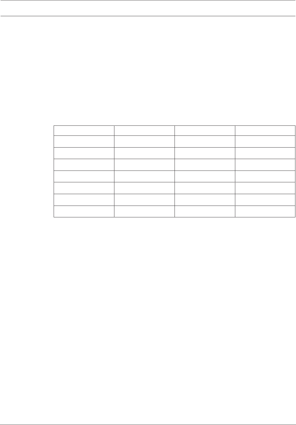
Decoding performance
Encoding Streams Resolution Max. bit rate
H.264 MP 2 12MPp20 20Mbps
H.264 4KUHD 2 2160p30 20Mbps
H.264 HD 6 1080p30 10Mbps
8 720p60 10Mbps
12 720p30 10Mbps
H.264 SD 30 4CIF/432p 6Mbps
60 4CIF/432p 2.5Mbps
Access security
The decoders offer various security levels for accessing the network, the unit, and the data
channels. System access is password-protected with two levels.
Malware resistance
VIDEOJETdecoder has been designed to be resistant to viruses and other malware. To
prevent security holes, the installed Bosch software limits transactions to operation and
maintenance and the embedded operating system is tailored to the needs. No other than
Microsoft and Bosch software is running on the decoder. Its firewall performs at the highest
security level and allows communication only for a minimum of needed services. All access is
password-protected, USB and other storage devices are disabled, and update files are
authenticated and encrypted, thus putting robustness against malicious software to the
highest degree.
Easy upgrade
Remotely upgrade the decoder whenever new firmware or software becomes available. This
ensures up-to-date products, thus protecting investment with little effort.

10 en | System overview VIDEOJET decoder 8000
2016.03 | V2 | DOC Installation manual Bosch Securtity Systems B.V.
Summary
VIDEOJET decoder8000 provides the following main functions:
– Video and audio reception over IP data networks
– H.264 or MPEG-4 decoding at up to 60frames per second
– Decoding of H.264 High Definition streams for up to six with 1080p30, or eight with
720p60, or twelve 720p30 streams, all at 10Mbps, at the same time
– Decoding of up to 30H.264 Standard Definition streams at up to 6Mbps at the same
time.
– Integrated Ethernet port (10/100/1000Base-T)
– Configuration and remote control of all internal functions via TCP/IP, also secured via
HTTPS
– Password protection to prevent unauthorized connection or configuration changes
– Convenient maintenance via uploads
– Flexible encryption of control and data channels
– Bidirectional audio (mono) via Mini DisplayPort DP1
– Audio encoding according to international standards G.711 and L16
VIDEOJET decoder 8000 System overview | en 11
Bosch Securtity Systems B.V. Installation manual 2016.03 | V2 | DOC
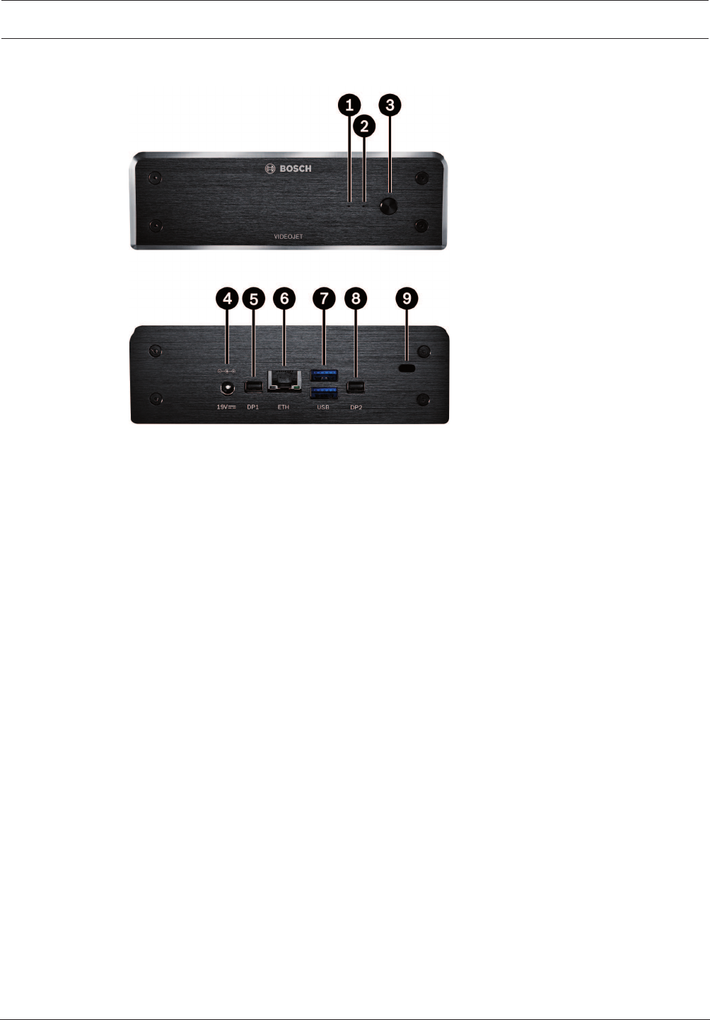
3.3 Connections, controls and displays
1SSD LED
lights orange on SSD activity
2Power LED
lights up blue when the unit is switched on
3Power switch
to turn the unit on or off
4DC power connector
for connecting the power supply unit that is included
5DisplayPort DP1
1 of 2 Mini DisplayPorts, also for audio transmission
6RJ45 socket ETH
for connecting to an Ethernet LAN (local network), 10/100/1000 MBit Base-T
72 ports USB
two dual USB 3.0
8DisplayPort DP2
1 of 2 Mini DisplayPorts
9Kensington lock
See also
– LEDs, page 19
12 en | Installation VIDEOJET decoder 8000
2016.03 | V2 | DOC Installation manual Bosch Securtity Systems B.V.
4 Installation
4.1 Preparations
VIDEOJET decoder8000 and the power supply unit are both intended for use indoors only.
Select a suitable location for installation that guarantees to meet the environmental
conditions.
Notice!
The ambient temperature for the unit must be between 0and+50°C (+32and+122°F). The
relative humidity must not exceed 90%.
The unit and the power supply unit generate heat during operation, so you should ensure that
there is adequate ventilation and enough clearance between both units and heat-sensitive
objects or equipment. Please note the maximum heat value of 221BTU/h per unit without the
power supply.
Please ensure the following installation conditions:
– Do not install the unit or the power supply unit close to heaters or other heat sources.
Avoid locations exposed to direct sunlight.
– All ventilation openings must be kept free from blockings. Do not stack several units one
on top of each other.
– Allow sufficient space for running cables.
– Ensure that both the unit and the power supply unit have adequate ventilation. Bear the
total heat output in mind, particularly when installing multiple units in a switch cabinet.
– When making connections, use only the cables supplied or use appropriate cables
immune to electromagnetic interference.
– Position and run all cables so that they are protected from damage, and provide adequate
cable strain relief where needed.
– Avoid impacts, blows, and severe vibrations that exceed the specification limits, as these
can irreparably damage the unit.
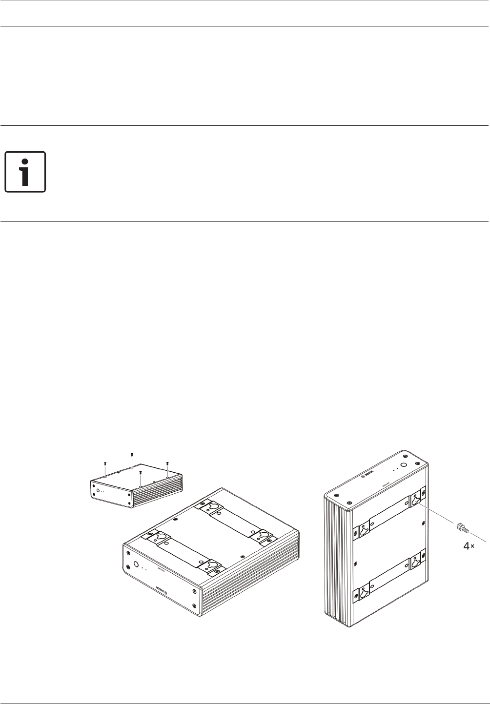
4.2 Mounting
The decoder comes with four stands. Place the unit upon an appropriate flat surface from
which it cannot fall down.
As an alternative, you can mount the decoder to an approved monitor using the supplied
mounting kit.

VIDEOJET decoder 8000 Installation | en 13
Bosch Securtity Systems B.V. Installation manual 2016.03 | V2 | DOC
!
Caution!
Injuries by falling equipment
The mounting location must be able to reliably hold the unit. The load-bearing capacity must
be adequate for four times the weight of the unit.
If mounting the unit to the back of a monitor, use only monitors with standard VESA mount.
When mounting the unit on the rear side of a monitor, ensure that there is adequate
ventilation and enough clearance between both units and walls or other monitors, especially
with several monitors mounted side by side on a wall.
1. Remove the four stands on the bottom of the decoder. Put the screws aside for step 3.
Retain the stands for future usage.
2. Place the mounting brackets supplied as shown in the picture. Make sure that the
keyholes point in the same direction.
3. Fasten the brackets with the screws.
4. Fasten the VESA mounting screws supplied to the monitor.
5. Hook the keyholes onto the VESA screw heads and slide the decoder down to secure.
Preferably, mount the decoder with connections facing downwards to ensure best
ventilation.
14 en | Connection VIDEOJET decoder 8000
2016.03 | V2 | DOC Installation manual Bosch Securtity Systems B.V.
5 Connection
5.1 Sequence of connections
Notice!
Do not connect the decoder to the power supply until all other connections have been made.
Otherwise the automatic assignment of the IP address will fail and a faulty monitor resolution
will be set. This may lead to serious damage of the unit.
5.2 Connecting monitors
You must connect a suitable monitor to the decoder. If mounting the unit to the back of a
monitor, use only monitors with standard VESA mount.
The unit provides two Mini DisplayPorts as monitor outputs which can be used at the same
time.
4Connect each monitor using the respective monitor cable or adapter.
VGA connections are not supported.
5.3 Establishing the network connection
You must connect the decoder to a 10/100/1000Base-T network using a standard UTP
category5 cable with RJ45 plugs.
4Connect the unit to the network via the RJ45 socket.
When the decoder is powered after finalizing all connections, the LEDs on the RJ45 socket
light up to indicate that the network connection has been set up correctly. Flashing green, the
left LED signals that data packages are being transmitted over the network.
See also
– LEDs, page 19
5.4 Connecting audio
The decoder has no dedicated audio port. Audio is transmitted digitally via monitor output
DP1. There is no audio transmission for monitor output DP2.
5.5 Connecting the power supply
Power is supplied via a separate power supply unit that is part of the delivery. It offers two
power cords, one for EU and one for US.
Notice!
Use only the power supply unit that is included, together with the suitable power cord.
Connect the unit to an earthed mains socket-outlet.
Do not connect the decoder to the power supply until all other connections have been made.
1. Connect the decoder to the power supply unit.
2. Select the suitable power cord and plug this into the power supply unit and then into the
mains.
The unit is now ready for use.
5.6 Power on/power off
VIDEOJET decoder8000 is equipped with a power switch on its front panel.

VIDEOJET decoder 8000 Connection | en 15
Bosch Securtity Systems B.V. Installation manual 2016.03 | V2 | DOC
The VIDEOJET decoder 8000 automatically starts up when connected to mains power. The
blue LED on the front next to the switch lights up. During the boot process, the orange LED
flashes.
1. Switch on the monitor in order to see the user interface after the boot-up procedure.
2. To switch off, press the power switch. The blue LED turns off.
3. Press the power switch again to switch on the unit.
All information regarding the functions and the operation can be found in the relevant
documentation of MonitorWall, Bosch Video Management System, or VideoClient.
See also
– LEDs, page 19
16 en | Configuration VIDEOJET decoder 8000
2016.03 | V2 | DOC Installation manual Bosch Securtity Systems B.V.
6 Configuration
This chapter is intended for the administrator of the video management system. The setup
process depends on the video management system in use. Refer to the corresponding
documentation for details. In this manual, the setup with the BoschVideoClient system is
explained as example.
6.1 Setting up the decoder with Configuration Manager
Before you can operate the unit within your network, it must have a valid IP address for your
network and a compatible subnet mask.
Notice!
As a default DHCP is enabled in the unit’s network settings.
With an active DHCP server in the network you must know the IP address assigned by the
DHCP server to operate the unit.
The following default address is preset at the factory: 192.168.0.1
For the latest version of the Configuration Manager, go to http://www.boschsecurity.com and
download it from the Software tab of the corresponding product page.
In Configuration Manager, the decoder currently is detected in the same way as other
hardware, various information is displayed, and further configuration options are provided. In
the following, the configuration pages found in the Configuration Manager for the decoder are
listed, and the different settings explained.
Notice!
Changes do not become effective until you click in the toolbar.
Find more information in the documentation for the Configuration Manager.
6.1.1 Unit Access tab
Identification
In this group, assign a unique name and ID for the decoder in order to make administering of
multiple units easier in larger installations.
Password
In this group, you can protect the decoder against unauthorized access.
The decoder works with two password levels. The service level is the highest level of
authorization. With this level of access, after entering the required password, users can use all
functions of the decoder and change all configuration settings. The user level enables users to
make and break connections or switch layouts, but does not provide access to configuration.
Device access (main tab My Devices only)
This group controls access from the Configuration Manager to the decoder. Here, you can
configure settings to determine which protocol and which HTTP port are used for
communication between the Configuration Manager and the decoder.
If the decoder is password-protected, the correct user name and password must be entered
here.
Version information
In this group, you can view the hardware, firmware versions and serial number of the decoder.

VIDEOJET decoder 8000 Configuration | en 17
Bosch Securtity Systems B.V. Installation manual 2016.03 | V2 | DOC
6.1.2 Advanced tab
In the Video windows group, you edit the default display of the cameos. Cameos are the
viewlets which show the video stream in your video management system.
Notice!
The settings in this area apply to all cameos. You cannot configure settings here for individual
cameos.
Ignore video aspect ratio
With this parameter you define the handling if the cameo and the video stream aspect ratio
are not matching. Choose Off to display the original video stream aspect ratio; unused cameo
space is blackened. Choose On to use the complete cameo; overhanging video is cut off.
Aspect ratio
Select the default aspect ratio for cameos. Choose the ratio that is appropriate for most of
your video sources.
Metadata
Define if you want to display metadata overlays in the video. Metadata overlays will only be
shown if provided with the connected video stream.
Video smoothing
Due to network jitter decoded videos might be jerky. You can improve the smoothness with
the disadvantage that the video display is delayed. The higher the selected value, the
smoother the video but the greater the time delay. Select 0(zero) to disable video smoothing.
Distance between cameos
Set your preferred distance between the cameos.
Reconnect on restart
If you enable this parameter the previous session is restored anytime you restart the decoder.
If Reconnect on restart is disabled connections must be manually reestablished after
restarting the decoder.
Number of decoders
Define the maximum number of cameos limiting the number of possible connections, for
example to match the licensed channels of your video management system.
Destination
Set the password to restrict connections between decoders and video sources. Only video
sources which have that password entered as Destination password, can setup a connection
to the decoder.
It can be used as a general password. Find more information in the documentation for the
video sources.
Display resolution
By default, Resolution adaptation is set to automatic mode. Thus, on start the optimum
resolution for the display device is selected.
The manual mode should only be used for project-specific adaptations by personnel qualified
by Bosch.
6.1.3 Network Access tab
In this area, you define the network settings for the decoder.
Device IP address
In this box, enter an IP address that is valid in the network.
18 en | Configuration VIDEOJET decoder 8000
2016.03 | V2 | DOC Installation manual Bosch Securtity Systems B.V.
Subnet mask
Enter an appropriate subnet mask for the IP address.
Gateway address
If required, enter an appropriate gateway address.
Notice!
A new IP address, or a new subnet mask or gateway address, does not become valid until the
decoder is restarted.
After entering all required addresses, it is necessary to restart the decoder:
1. In the toolbar, click .
2. Confirm the restart.
3. After restart, the software is available for use under the new addresses.
6.2 Integrating the decoder into the video system
In order to integrate the decoder into a video management system which only operates the
decoder, relevant settings can be made with the Configuration Manager.
1. Start the decoder.
2. Start Configuration Manager on a separate PC.
3. Configuration Manager automatically scans the network for compatible devices. The
software detects the decoder and lists it in the main tab Devices.
4. In the list of identified devices, right-click the entry for the decoder.
The pop-up menu appears.
5. Select the Add to System... command from the pop-up menu.
The Add Device to System dialog box is displayed.
6. You can select an existing group into which you want to integrate the decoder.
To create a new group, enter a name for the group.
You can also continue without selecting or creating a group.
7. Click OK.
8. Switch to the main tab My Devices.
The decoder appears in the list of devices assigned to the system.
6.3 Configuring the decoder with Video Client
For a detailed description to integrate the software in the VideoClient application, see the
VideoClient documentation.
Monitor wall tab
You can only set up a monitor wall if you have added decoders to your system. The available
decoders are listed in the Decoders box. Decoders that belong to a site are only listed if the
site is connected.
Note that this tab is not available if you have used direct logon.
1. Drag a decoder from the Decoders box to a free position on the monitor wall grid.
Alternatively, select a decoder and a free position and click .
2. Drag a decoder in the grid to a new position to rearrange the grid.
3. To free a position, select it and click . The decoder is removed from the grid and
listed in the Decoders box.
VIDEOJET decoder 8000 Troubleshooting | en 19
Bosch Securtity Systems B.V. Installation manual 2016.03 | V2 | DOC
7 Troubleshooting
7.1 Contact
If you are unable to resolve a malfunction, please contact your supplier or systems integrator,
or go directly to Bosch Security Systems Customer Service.
The following tables are intended to help you identify the causes of malfunctions and correct
them where possible.
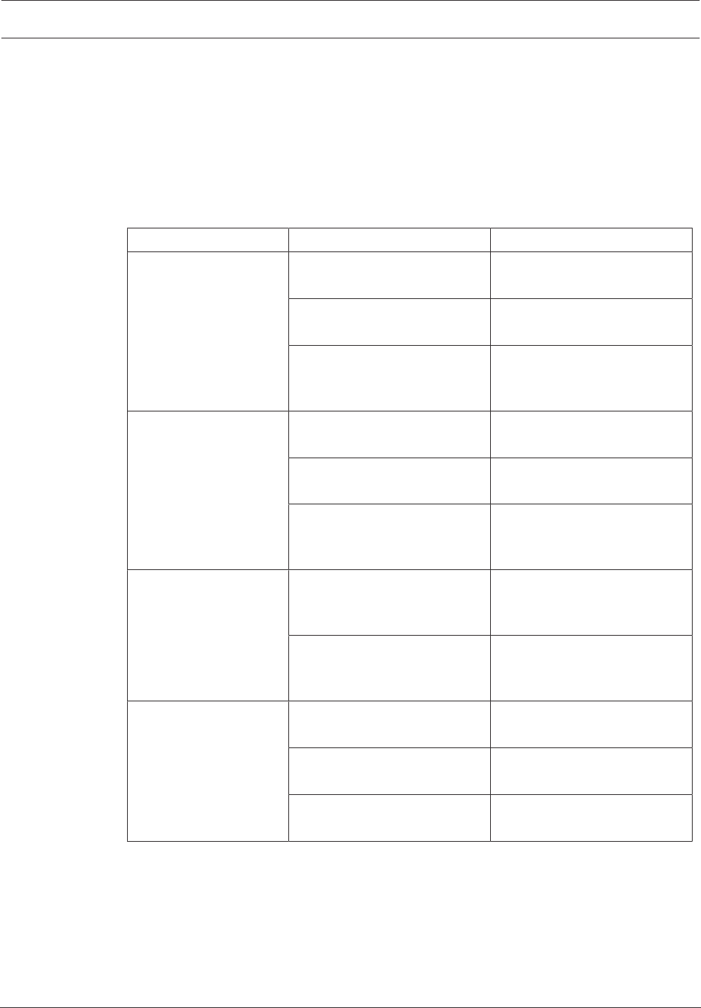
7.2 General malfunctions
Malfunction Possible causes Recommended solution
No image on the
monitor.
Monitor settings. Check the input selection at the
monitor.
Faulty cable connections. Check all cables, plugs and
connections.
Monitor fault. Connect another monitor to the
unit or use another monitor
connection.
No audio. Hardware fault. Check that all connected audio
units are operating correctly.
Faulty cable connections. Check all cables, plugs and
connections.
Wrong DP port used. Check that connection uses
DP1; DP2 does not support
audio.
The unit is not
operational after a
firmware upload.
Power failure during
programming by firmware file.
Have the unit checked by
Customer Service and replace
it, if necessary.
Incorrect firmware file. Have the unit checked by
Customer Service and replace
it, if necessary.
The power light is not lit. Unit not switched on. Press the main switch on the
front panel.
Unit not connected to the
power supply unit.
Check all cables, plugs and
connections.
Power supply unit not
connected to the mains outlet.
Check all cables, plugs and
connections.
7.3 LEDs
The unit has LEDs on its front and rear panels that show the operating status and can give
indications of possible malfunctions:
Find the following LEDs on the front panel:
Power LED
Off: The unit is switched off or not connected to the power supply.

20 en | Troubleshooting VIDEOJET decoder 8000
2016.03 | V2 | DOC Installation manual Bosch Securtity Systems B.V.
Lights up blue: The unit is switched on.
SSD LED
Off: The unit’s SSD is not accessed.
Flashes orange: The unit’s SSD is accessed.
Find the following LEDs on the rear panel:
RJ45 socket LEDs
Left LED: Off: LAN connection not established.
Green: LAN connection established.
Blinking green: LAN activity occurring.
Right LED: Off: 10Mbps data rate.
Green: 100Mbps data rate.
Yellow: 1000Mbps data rate.

VIDEOJET decoder 8000 Maintenance | en 21
Bosch Securtity Systems B.V. Installation manual 2016.03 | V2 | DOC
8 Maintenance
8.1 Updates
Firmware and software updates are carried out via the Configuration Manager application or
other management systems in use. Please refer to the relevant documentation.
8.2 Repairs
– Never open the housing of the unit. The unit does not contain any user-serviceable parts.
– Never open the housing of the power supply unit. The power supply unit does not contain
any user-serviceable parts.
– Ensure that all maintenance or repair work is carried out only by qualified personnel
(electrical engineers or network technology specialists). In case of doubt, contact your
dealer's technical service center.
22 en | Decommissioning VIDEOJET decoder 8000
2016.03 | V2 | DOC Installation manual Bosch Securtity Systems B.V.
9 Decommissioning
9.1 Transfer
VIDEOJET decoder8000 should only be passed on together with this installation manual.
9.2 Disposal
Your Bosch product is designed and manufactured with high-quality materials and
components which can be recycled and reused.
This symbol means that electrical and electronic equipment, at their end-of-life, should be
disposed of separately from your household waste.
In the European Union, there are separate collection systems for used electrical and electronic
products. Please dispose of this equipment at your local community waste collection/recycling
center.

VIDEOJET decoder 8000 Technical data | en 23
Bosch Securtity Systems B.V. Installation manual 2016.03 | V2 | DOC
10 Technical data
10.1 Electrical
Power supply Wide-range, external, included in the box
Input voltage 100 to 240VAC, 50/60 Hz
Power consumption Approx. 15W, 65W max
10.2 Mechanical
Dimensions (H × W × D) 47.3 × 150.6 × 186mm (1.862 × 5.929 × 7.323in), without stands
Weight Approx. 1.7kg (3.7lb)
VESA mount 100 × 100mm
(3.937 × 3.937in)
Video 2 × Mini DisplayPort, no VGA support
Audio Audio is transmitted digitally via monitor output DP1.
Front indicators 2 × LED (power, SSD)
Rear connectors 1 × DC power connector
2 × dual USB 3.0
1 × Ethernet port
2 × Mini DisplayPort
10.3 Environmental conditions
Operating temperature 0°C to +50°C (+32°F to +122°F)
Relative humidity 0 to 90% atmospheric humidity, non-condensing
Thermal value Approx. 51BTU/h, 221BTU/h max
10.4 Certifications and approvals
Safety IEC 60950
Electromagnetic
compatibility
EN55022
EN55024
FCC 47 CFR Chapter 1 Part 15
Approvals CE, UL
10.5 Standards
Video H.264 (ISO/IEC 14496-10), MPEG-4
Video data rates Up to 20Mbps per stream (MP)
GOP structure I, IP, IBBP
Monitor resolutions DP: 3840 × 2160 (UHD) at 60Hz
Audio G.711: 300Hz to 3.4kHz
L16 (reception only): 300Hz to 6.4kHz

24 en | Technical data VIDEOJET decoder 8000
2016.03 | V2 | DOC Installation manual Bosch Securtity Systems B.V.
Audio data rate G.711: 80kbps at 8kHz sampling rate
L16: 640kbps at 16kHz sampling rate
Signal-to-noise ratio >50dB
Ethernet 10/100/1000 Base-T, auto-sensing, half/full duplex, RJ45
Protocols IPv4, UDP, TCP, HTTP, HTTPS, RTP/RTCP, IGMP V2/V3, ICMP,
ARP, DHCP, APIPA (Auto-IP, link local address), NTP (SNTP),
digest authentication
Encryption TLS 1.0, SSL, 3DES, AES

VIDEOJET decoder 8000 Index | en 25
Bosch Securtity Systems B.V. Installation manual 2016.03 | V2 | DOC
Index
A
Audio connections 11, 14
C
Conventions 7
D
Danger 5
Decoding performance 9, 10
DHCP 16
E
Electromagnetic compatibility 7
I
Identification 7
Installation 5
Installation conditions 12
Installation location 12
L
Low Voltage Directive 7
M
Main functions 10
Maintenance 5, 21
N
Network 14
Network connection 11
O
Operation 5
P
Power supply 5, 14
Power switch 14
R
Regulations 7
Repair 5, 21
S
Safety 5
Serial number 7
Symbols 7

26 en | Index VIDEOJET decoder 8000
2016.03 | V2 | DOC Installation manual Bosch Securtity Systems B.V.
Bosch Sicherheitssysteme GmbH
Robert-Bosch-Ring 5
85630 Grasbrunn
Germany
www.boschsecurity.com
© Bosch Sicherheitssysteme GmbH, 2016
