Bose 311822 Transceiver Module User Manual MANUAL AND LABELING REQUIREMENTS
Bose Corporation Transceiver Module MANUAL AND LABELING REQUIREMENTS
Bose >
Manual
IR / 2.4GHz RF Modular Transceiver
Installation manual (draft v3)
1. Description
This drawing describes an RF / IR remote control transceiver module PCB. The
module is part of a panel of PCB’s defined by PT311822 and associated drawings.
The module consists of 3 separate circuits :
1) A 2.4GHz RF transceiver IC and etch antenna for use with an RF remote
2) An IR remote control transmitter
3) An IR remote control receiver
There is also a pair of LED for indication purposes
2. Cautions:
This transceiver module is ONLY to be installed in Bose Corporation devices.
This device complies with Part 15 of the FCC Rules. Operation is subject to the
following two conditions: (1) this device may not cause harmful interference, and (2)
this device must accept any interference received, including interference that may
cause undesired operation
Changes or modifications not expressly approved by Bose Corporation could void the
user’s authority to operate the equipment.”
NOTE: This equipment has been tested and found to comply with the limits for a
Class B digital device, pursuant to Part 15 of the FCC Rules. These limits are
designed to provide reasonable protection against harmful interference in a residential
installation. This equipment generates, uses and can radiate radio frequency energy
and, if not installed and used in accordance with the instructions, may cause harmful
interference to radio communications. However, there is no guarantee that
interference will not occur in a particular installation. If this equipment does cause
harmful interference to radio or television reception, which can be determined by
turning the equipment off and on, the user is encouraged to try to correct the
interference by one or more of the following measures:
− Reorient or relocate the receiving antenna.
− Increase the separation between the equipment and receiver.
− Connect the equipment into an outlet on a circuit different from that to which the
receiver is connected.
− Consult the dealer or an experienced radio/TV technician for help.

3. Markings
3.1 This module shall be identified with the following ID numbers on the PCB
silkscreen
FCC ID : A94311822
IC : 3232A-311822
3.2 End Product Labeling
The final end product which this module is used in must be labeled in a visible
area with the following:
"Contains FCC ID: A94311822 / IC:3232A-311822"
4. Connections
The following table describes the connections to the module made via connector
J800
Pin
# Name Description
1 IR_RCV_DATA IR receiver data output
2 IR_DRIVE IR LED supply
3 +3.3v Power supply
4 CC_DATA_IN RF transceiver IC serial data input
5 GND Ground
6 CC2500_CLCK RF transceiver IC serial clock
7 GND Ground
8 CC_DATA_OUT RF transceiver IC serial data output
9 GND Ground
10 MESSAGE_INT RF transceiver IC interrupt ouput line (to host micro)
11 PWR_RMT_LED2 Red LED (connect to ground via series R to light)
12 CC2500_CS RF transceiver IC chip select
13 PWR_RMT_LED1 Green LED (connect to ground via series R to light)
5. General Electrical specifications
5.1 Power supply 3.3v +/- 5%
5.2 Operational Temperature 0 ~ 45 C (non-condensing)
5.3 Display LED Current 1.3mA typical
5.4 IR Transmitter Current 150mA typical peak
6. 2.4GHz RF Transceiver
The RF transceiver uses a TI CC2500 low cost, low power RF transceiver IC to drive
a 50 ohm etch antenna via a simple balun and matching network. A switched coaxial
connector is provided for test purpose to measure the output power from the IC and
balun
6.1 Electrical Specification
For a detailed description of the CC2500 and the most recent electrical
specification see PT301591-001 (vendor part spec SWRS040C 08_05_04.pdf
available on TI web site).
The module shall use the following settings :
6.1.1 RF Output Power : +1dBm typical (measured at J801)
6.1.2 Useable Frequency Range: 2401.67 – 2482 MHz
6.1.3 Modulation 250kbaud GFSK with data whitening
6.1.4 Channel Spacing 333kHz
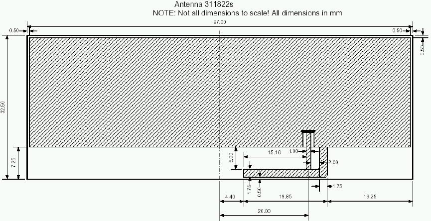
6.2 Antenna Specification
The RF module uses an etch antenna whose dimensions and position on the
board where determined assuming an ideal ground plane of approximately the
dimensions of the actual PCB – as shown below
7. IR Transmitter
Refer to PT256733 for detailed electrical specifications of the IR LED’s
8. IR Receiver
The module contains 2 IR receiver circuits. These are selected using a GPIO on the
CC2500 – controllable via the serial data bus for the IC
8.1 A narrow band (38kHz) IR receiver – Part #319144-038
8.2 A wide band IR receiver constructed from 2 narrow band IR receivers at 38kHz
and 56kHz (part # 319144-038 and 319147-156 respectively)