Bose 420128RM Wireless Audio Module User Manual 9 11 11005838 420128RM Theory of Op Install Manual v3
Bose Corporation Wireless Audio Module 9 11 11005838 420128RM Theory of Op Install Manual v3
Bose >
9 & 11_11005838_420128RM_Theory of Op Install Manual v3

Model 420128RM Wireless Link Module
External Interface Specification
2016/6/13
Introduction
Model 420128RM Wireless Link Module is for the low latency wireless link between console and
bass box or rear surround speaker or both.
This document shows how to connect the wireless module.
Features and Functions
• 2.4GHz, 5.2GHz, 5.8GHz, 5.2/5.8GHz dual band, 2.4/5.2/5.8GHz tri band
o All band usage is under active software control according to each regional and
country band plan assignments. Where the use of any band conflicts with local
regulations, the radio will be locked out of that band.
• 22Mbps data rate (15 MHz nominal channel bandwidth).
• Modulation - QPSK
• Antenna types –Inverted F with following gains:
2.4 GHz
5.2GHz
5.8GHz
Antenna-A
1.98 dBi
4.18 dBi
4.98 dBi
Antenna-B
2.2 dBi
5.02 dBi
5.56 dBi
• Target Power –
Band (GHz)
Target Power
2.4
3.08 dBm + 2dB
5.2
8.83 dBm + 2dB
5.8
9.31 dBm + 2dB
• One module design can be used for both source and sink
o Source : Central Unit (CU)
o Sink : Mobile Unit (MU)
• Bi-directional audio and data
• Up to four uncompressed stereo audio channels (max 7.1ch configuration)
• I2S for audio
o Input (Source) : 44.1kHz, 48kHz
o Output (Sink) : 48kHz
• I2C for control
1 of 10
Connection
Wireless (Module to Module)
• Point to point
• Point to multi point
Module to PCB
• 26 pin FFC
2 of 10
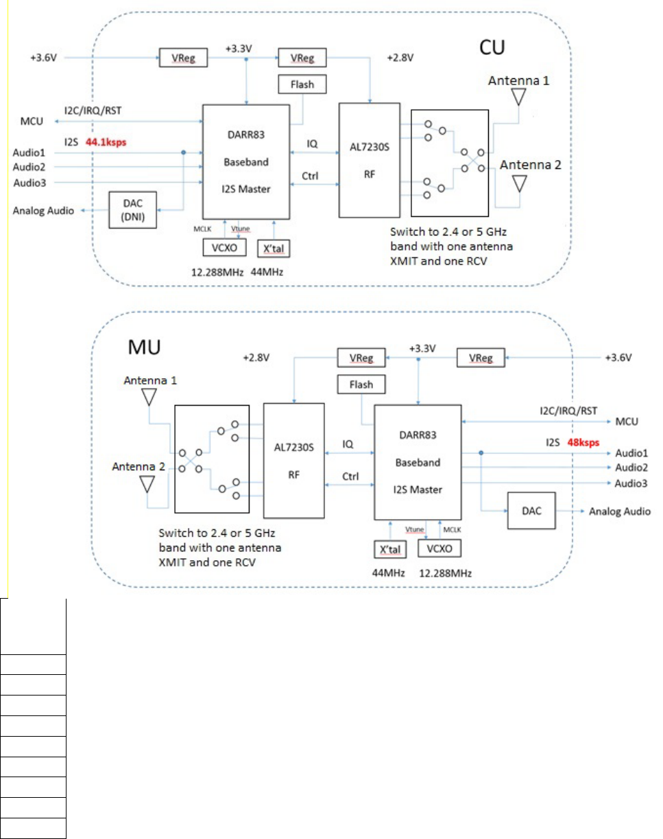
Block diagram
Bose module
Radio
Output
(MHz)
2412.0
2438.0
2464.0
5180.0
5210.0
5240.0
5736.0
5762.0
5814.0
3 of 10

FFC Connector pin assignment
Bose module
Pin#
Wireless Module
Console Main
Bassbox
Rear Right
Rear Left
Header
1
+3.6V to +5V
+3.6V
+3.6V
+3.6V
+3.6V
1
2
GND
GND
GND
GND
GND
2
3 MCLK 12.288MHz AUDIO_MCLK
MCLK
12.288MHz
MCLK
12.288MHz
MCLK 12.288MHz
3
4
nc
nc
nc
nc
nc
5
DAC_LEFT_P
nc
Analog_In_P
Analog_In_P
Analog_In_P
4
6
DAC_LEFT_N
nc
Analog_In_N
Analog_In_N
Analog_In_N
5
7
nc
nc
nc
nc
nc
8
nc
nc
nc
nc
nc
9
DARR83_GPIO_3
SYNC_LED
SYNC_LED
SYNC_LED
SYNC_LED
6
10
GND
GND
GND
GND
GND
11
GND
GND
GND
GND
GND
7
12
GND
GND
GND
GND
GND
13
DARR83_GPIO_24
MON_TXD
MON_TXD
MON_TXD
MON_TXD
8
14
DARR83_GPIO_14
RADIO_IRQ
RADIO_IRQ
RADIO_IRQ
RADIO_IRQ
9
15
GND
nc
nc
nc
nc
16
DAC_RST_L
nc
DAC_RST_L
DAC_RST_L
DAC_RST_L
10
17
DARR_RST_L
RADIO_RST_L
RADIO_RST_L
RADIO_RST_L
RADIO_RST_L
11
18
I2C_SCL_Slave
RADIO_SCL
RADIO_SCL
RADIO_SCL
RADIO_SCL
12
19
I2C_SDA_Slave
RADIO_SDA
RADIO_SDA
RADIO_SDA
RADIO_SDA
13
20
DARR83_GPIO_12
nc
nc
nc
nc
14
21
DARR83_GPIO_11
RADIO_DATA1
nc
RADIO_DATA1
RADIO_DATA1
15
22
DARR83_GPIO_10
AUDIO_LRCLK
AUDIO_LRCLK
AUDIO_LRCLK
AUDIO_LRCLK
16
23
GND
GND
GND
GND
GND
17
24
DARR83_GPIO_8
AUDIO_BCLK
AUDIO_BCLK
AUDIO_BCLK
AUDIO_BCLK
18
25
DARR83_GPIO_6
RADIO_DATA2
nc
nc
nc
19
26
DARR83_GPIO_5
RADIO_DATA3
RADIO_DATA3
nc
nc
20
• Pin# is for Flat Flex Cable connector
o Bose part # : 715435-26S2
o Hirose FH12-26S-0.5SH
o Side entry
o Bottom contact
• Console/BB/Rear board must use same connector and FFC must be opposite side contact.
• Header is dual row
4 of 10

Specification
System specification
Parameter
Value
Unit
Remarks
RF Characteristics
RF Frequency Range
2400 – 2483.5
5150 – 5250
5725 – 5875
MHz
MHz
MHz
2412, 2438, 2464 MHz
5180, 5210(5200 in Japan), 5240 MHz
5736, 5762, 5814 MHz
RF Bandwidth
22
MHz
RF TX power
3
9
9
dBm
dBm
dBm
2.4GHz
5.2GHz
5.8GHz
RF RX sensitivity
-83
-81
-81
dBm
dBm
dBm
2.4GHz
5.2GHz
5.8GHz
RF Antenna
2 Dual Band Etched F
2.4G/5G dual band etched antenna and
jumper and RF connector for external
antenna option
RF Connector
u.FL
Air Framing
Addressing
24
Bit
Data message size
32
Byte
Application dependent
CRC
16, 24 and 32
Bit
Control
Control interface
I2C
Data
Data Bandwidth
100
Kbps
Bi-directional wireless data channel
Data latency
5
ms
Audio
Audio interface
I2S
Standard, left, right justified selectable
Master clock
12.288
MHz
48kHz x 256
Number of stereo audio
output channels on
Mobile Unit
1, 2, 3 or 4
Max 4, only use 1 in MU(Receiver)
SW configure appropriate wireless burst
to single channel output
Number of stereo audio
output channels on
Central Unit
1, 2, 3 or 4
Max 4, only use 2 in CU(Console)
Rear L/R and Bass
Input Sample rate
44.1, 48 or 96
ksps
DARR83 must be slave mode to use SRC
Output Sample rate
48
ksps
Sample width
16 or 24
Bit
Latency
20
ms
Configurable from 10 to 23.6ms,
depending on the application.
Dynamic range
98
146
dB
dB
16bit 48ksps, A-weighted
24bit 48ksps, A-weighted
THD+N
-96
-143
dB
dB
16bit 48ksps
24bit 48ksps
5 of 10
Absolute Maximum Rating
Symbol
Parameter
Min
Max
Unit
Remarks
Vcc
Supply Voltage
3.5
3.8
5.2
V
V
DP0.1
DP1 or later
Recommended Operating Conditions
Symbol
Parameter
Min
Typ
Max
Unit
Remarks
Vcc
Supply Voltage
3.1
3.3
3.6
3.5
V
V
DP0.1
DP1 or later
Vcc ripple
Peak to Peak ripple
0
100
mV
DP0.1
Tamb
Operating Temp
-10
25
60
°C
Reset timing characteristics
Symbol
Parameter
Min
Typ
Max
Unit
Remarks
Tr
Rise time of Vcc
10
ms
Tf
Fall time of Vcc
10
ms
Treset
Reset signal pulse width
1
ms
Power consumption (Vcc=3.3V, 25°C)
Application
2.4GHz
5.2GHz
5.8GHz
Unit
MU
CU
MU
CU
MU
CU
Standby mode
21
21
21
21
21
21
mA
2 Stereo NACK
81
140
82
124
82
127
mA
TX continuous (Test)
390
300
300
mA
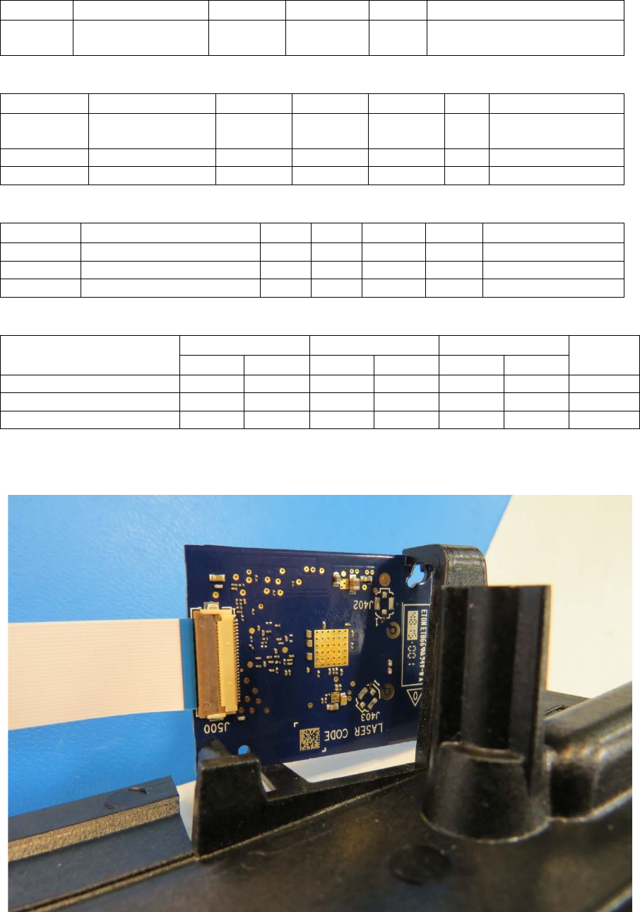
Module Photo
6 of 10
For 2.4G Device
NCC 警語
低功率電波輻射性電機管理辦法
第十二條經型式認證合格之低功率射頻電機,非經許可,公司、商號或使
用者均不得擅自變更頻率、加大功率或變更原設計之特性及功能。
第十四條低功率射頻電機之使用不得影響飛航安全及干擾合法通信;經發
現有干擾現象時,應立即停用,並改善至無干擾時方得繼續使用。
前項合法通信,指依電信規定作業之無線電信。低功率射頻電機須忍受合法通信
或工業、科學及醫療用電波輻射性電機設備之干擾
For 2.4G Device
NCC Warning Statement
Article 12
Without permission, any company, firm or user shall not alter the frequency, increase the power,
or change the characteristics and functions of the original design of the certified lower power
frequency electric machinery.
Article 14
The application of low power frequency electric machineries shall not affect the navigation safety
nor interfere a legal communication, if an interference is found, the service will be suspended until
improvement is made and the interference no longer exists
To reduce any potential for harmful interference to co-channel MSS operations
7 of 10
For 5G Device
NCC 警語
低功率電波輻射性電機管理辦法
第十二條經型式認證合格之低功率射頻電機,非經許可,公司、商號或使
用者均不得擅自變更頻率、加大功率或變更原設計之特性及功能。
第十四條低功率射頻電機之使用不得影響飛航安全及干擾合法通信;經發
現有干擾現象時,應立即停用,並改善至無干擾時方得繼續使用。
在5.25-5.35 秭赫頻帶內操作之無線資訊傳輸設備,限於室內使用。
前項合法通信,指依電信規定作業之無線電信。低功率射頻電機須忍受合法通信
或工業、科學及醫療用電波輻射性電機設備之干擾
For 5G Device
NCC Warning Statement
Article 12
Without permission, any company, firm or user shall not alter the frequency, increase the power,
or change the characteristics and functions of the original design of the certified lower power
frequency electric machinery.
Article 14
The application of low power frequency electric machineries shall not affect the navigation safety
nor interfere a legal communication, if an interference is found, the service will be suspended until
improvement is made and the interference no longer exists
Within the 5.25-5.35GHz band, U-NII devices will be restricted to indoor operations to reduce any
potential for harmful interference to co-channel MSS operations
CAUTION: Changes or modifications not expressly approved could void your authority to
use this equipment
8 of 10
FCC STATEMENT
This device complies with Part 15 of the FCC Rules. Operation to the following two
conditions: (1) This device may not cause harmful interference, and (2) this device must
accept any interference received, including interference that may cause undesired
operation
INDUSTRY CANADA STATEMENT
This device complies with Industry Canada licence-exempt RSS standard(s). Operation is
subject to the following two conditions: (1) this device may not cause interference, and (2)
this device must accept any interference, including interference that may cause undesired
operation of the device.
Le présent appareil est conforme aux CNR d'Industrie Canada applicables aux appareils
radio exempts de licence. L'exploitation est autorisée aux deux conditions suivantes : (1)
l'appareil ne doit pas produire de brouillage, et (2) l'utilisateur de l'appareil doit accepter
tout brouillage radioélectrique subi, même si le brouillage est susceptible d'en
compromettre le fonctionnement.
RF Exposure - Min. 20 cm separation distance required for this module.
2.4 GHz statement – The radio module only supports Channels 2412, 2438, 2464 MHz and does
not support Channel frequencies 2467 MHz or 2472 MHz.
5 GHz UNII statement – This module supports automatic discontinue transmission as described in
15.407(c):
“The device shall automatically discontinue transmission in case of either absence of information
to transmit or operational failure. These provisions are not intended to preclude the transmission
of control or signalling information or the use of repetitive codes used by certain digital
technologies to complete frame or burst intervals.”
When the module is configured as a “Master” device, it will transmit digitally encoded
audio data as fed from the host system via an I2C data bus. If this data is malformed as
indicated by an incorrect data checksum. Transmission ceases. When configured as a
“Slave” device, the only transmissions occur after the reception of a data packet from the
Master. Lack proper data reception, a single transmission of “Not Acknowldge” to inform
the master of the failure. Lacking pairing with a Master device, the module is in receive
only mode.
9 of 10
Frequency stability 15.407(g).
“Manufacturers of U-NII devices are responsible for ensuring frequency stability such that an
emission is maintained within the band of operation under all conditions of normal operation as
specified in the users manual.”
This is accomplished by through the use of a crystal controlled oscillator having a
frequency tolerance of 20 parts per million in accuracy. This frequency is verified at
manufacture to be within these tolerances.
Labeling - For a host manufacture’s using this certified modular, an additional permanent label
referring to the enclosed module: “Contains Transmitter Module FCC ID: A94410128RM and IC:
3232A-420128RM” or “Contains FCC ID: A94410128RM and IC: 3232A-420128RM” must be used.
The host OEM user manual must also contain clear instructions on how end users can find and/or
access the module and the FCC ID.
10 of 10