Bose Rf273139_01D TTH Operators Manual Military Rf273139 01D
User Manual: Bose Triport Tactical Headset Series 2 – Bose Product Support
Open the PDF directly: View PDF ![]() .
.
Page Count: 25

CLASS
RF DWG NO.
273139
REVISIONS
REV DESCRIPTION CHECK ENG DATE
01 ECN-36327:UPDATE FIGURES;
CHANGE NAME TO TTH, UPDATE
EARCUSHION SECTION
VAB AM 11/04
01A UPDATE TO INCLUDE TTH S2 AM 07/10
01B UPDATED TTHS2 TT BATT. LIFE TO 240
HRS. AM 09/10
01C UPDATED TTHS2 VOLT. RANGE AM 07/11
01D VARIOUS UPDATES AM 10/11
APPLICABLE DOCUMENTS:
DOC
LVL DRAFTER
A. MANGIAMELI DATE
02/05/04
FRAMINGHAM, MA 01701-9168
3 CHECKER
J. BROWN
02/27/04 DESCRIPTION MANUAL, OPERATING &
2 ENGINEER
A. MANGIAMELI
02/05/04 MAINTENANCE (TTH & TTH Series 2)
1 RLS TO PROD
SIZE
A FSCM
32108 CLASS
RF DWG NO.
273139 REV.
01D
SHT 1 OF 25
Framingham, MA 01701-9168 SIZE
A FSCM
32108 CLASS
RF DWG NO. 273139 SHEET
2 of 25 REV.
01D
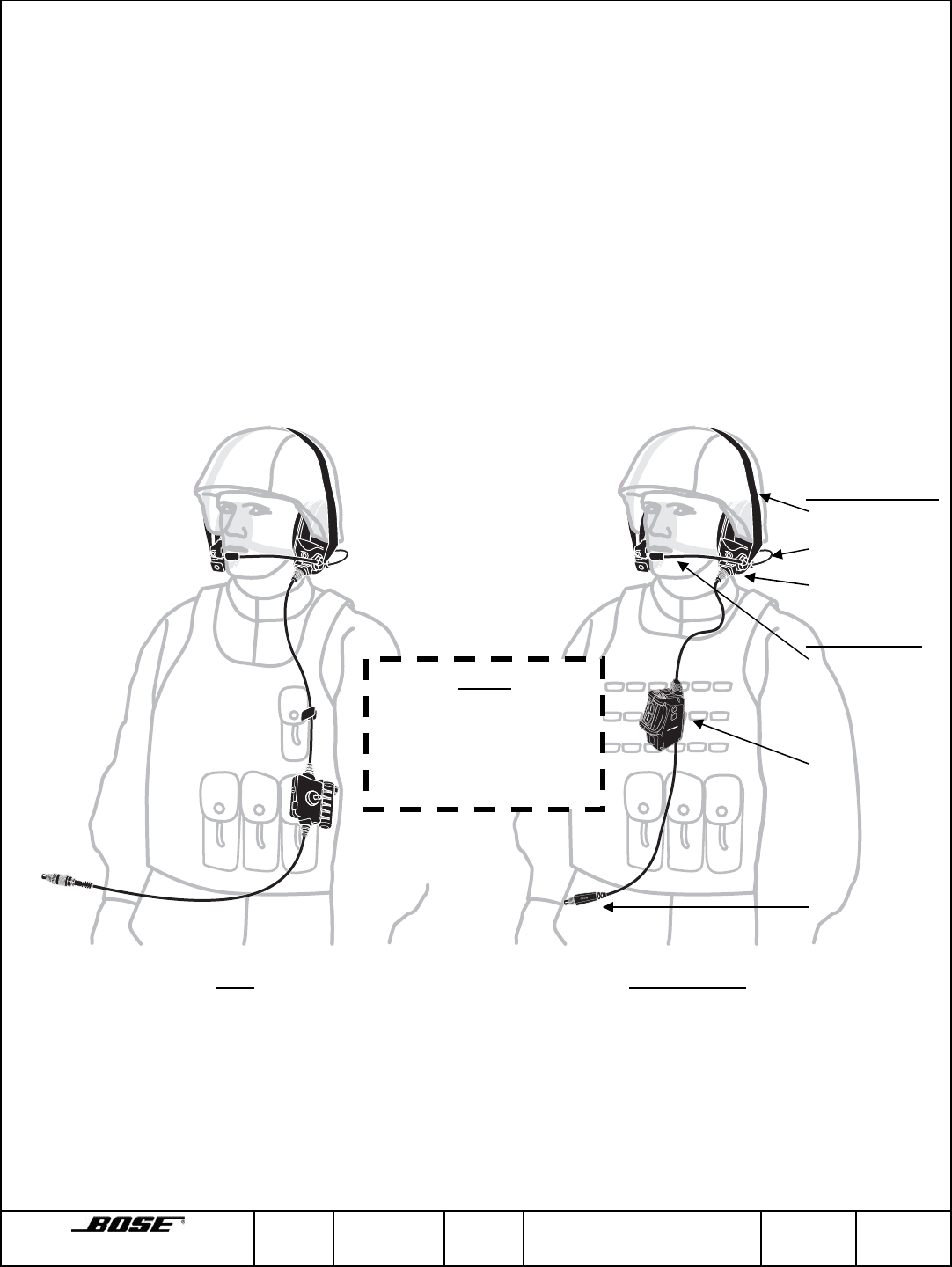
1. HEADSET FEATURES
The Bose® TriPort® Tactical Headsets (TTH & TTH Series 2) are active noise
reduction (ANR) communication headsets intended to be used by military
passengers of wheeled combat vehicles. The TTH headsets include an earcup
assembly (earcups and napeband) and a cable/microphone assembly. The
headsets adjust to fit various heads using adjustment overhead hook and loop straps
to ensure proper fit for noise attenuation. The cable/microphone can be installed on
either the left or right earcup.
In addition to passive attenuation each earcup contains an independent ANR
system. The ANR system reduces background noise within each earcup. The talk-
thru circuit (TTC) allows for local communication when the headset is either
connected or disconnected from the vehicle. The TTC is a user-selectable feature
and is powered via a single AA size battery in the control module and utilizes the
microphones on the front of each earcup. Each earcup has an independent TTC to
allow left/right localization.
TTH TTH Series 2
Earcup Assembly
• Overhead Strap
• Napeband
• Earcups
Cable/Mic Assy
• Noise-cancelling
microphone
• Control Module
• Vehicle Interface
Connector
NOTE
The control module
design is a key
differentiator between
TTH and TTH Series 2

Framingham, MA 01701-9168 SIZE
A FSCM
32108 CLASS
RF DWG NO. 273139 SHEET
3 of 25 REV.
01D
2. TECHNICAL INFORMATION
TTH TTH Series 2
Headset can be donned and
doffed without removing
helmet.
3 3
Cable/boom microphone
assembly is replaceable and
can be positioned on left or
right side.
3 3
Mono and stereo versions
available. 3 3
Weight (on head) 16 oz. maximum Same
Spring force (on head) 1.8 lbf. maximum Same
Push-to-talk (PTT) on the
control module 3-position (latched / off /
momentary) toggle type
switch
3-position (latched / off /
momentary) rocker type switch
Talk-through (TTC) User-selectable, Binaural,
up to 240 hours operational
time with one AA alkaline
battery
User-selectable, Binaural,
240 hours minimum
operational time with one AA
alkaline battery
ANR Power / Current Draw 5.5 to 32 VDC / 16 to 220 mA
Fail-safe operation allows 2-
way communications with
loss of voltage input or talk-
through power.
13.5 to 32 VDC / 38 mA Peak
except during turn-on
Fail-safe operation allows 2-
way communications with loss
of voltage input or talk-through
power.
Operating noise environment Up to 95dBA SPL Same
Earphone sensitivity 106 ± 3 dB SPL for a 0 ± 0.1
dBV input Same
Input Impedance 500 ± 10 ohms Same
Boom microphone 150 ± 22.5 ohm Impedance
-70 ± 4 dB sensitivity 150 ± 22.5 ohm Impedance
-70 ± 4 dB sensitivity
Dust proof
Temperature Rating -40oC to +65oC Operating
-57oC to +71oC Storage -40oC to +65oC Operating
-57oC to +71oC Storage
EMI Qualified for fields up to 50
V/m Qualified for fields up to 50
V/m with improved
performance for reduced audio
interference with the latest IED
jamming devices and other
electronics.
Attachment Clip Cable mounted Mounted on the control
module and compatible with
MOLLE webbing. Clip is
removable and may be
attached to either side of the
control module and rotated
into three different positions.

Framingham, MA 01701-9168 SIZE
A FSCM
32108 CLASS
RF DWG NO. 273139 SHEET
4 of 25 REV.
01D
3. HEADSET CONNECTORS AND CONTROLS
The connectors and controls for the TTH and TTH Series 2 headsets are integrated
into the cable/microphone assembly normally attached to the left earcup of the
headset. The assembly may be mounted on the right earcup if desired.
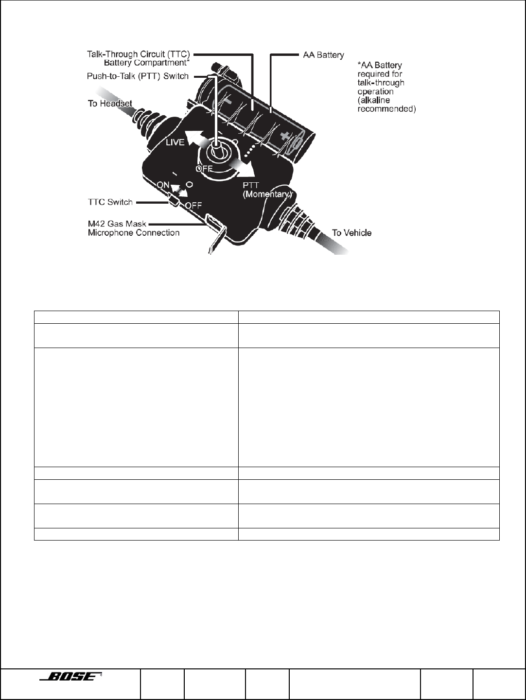
The control module on the cable/microphone assembly has a three-position push-to-
talk (PTT) switch as well as a two-position talk-thru circuit (TTC) switch as shown in
Figure 2.0b and 2.0c. The PTT switch is mounted on the face of the control module
and is spring loaded to the center (disabled) position with a momentary PTT position
and latched live intercom position. The control module may also be connected to the
communications microphones typically installed on protective masks. When the
external microphone connector is connected, the control module automatically
disengages the headset boom microphone to receive signals from the external
microphone.
Framingham, MA 01701-9168 SIZE
A FSCM
32108 CLASS
RF DWG NO. 273139 SHEET
5 of 25 REV.
01D
Figure 2.0b TTH Control Module Features
COMPONENT FUNCTION
Microphone Boom and Cable Assembly Transmits user’s voice into intercom or radio
channel
PTT Switch Used when transmitting on and listening to intercom
channel or radio. The latched position allows the
user to communicate on the vehicle intercom.
The OFF (center position allows the user to listen
only.
The Momentary (down) position allows the user to
communicate on the vehicle intercom and the
selected radio. Please note that these function
could vary by intercom. Please consult the intercom
manual.
Vehicle Interface Connector Provides quick-disconnect for operator.
TTC Switch Used to monitor ambient noise environment when
desired.
M42 Gas Mask Microphone Connection Allows M116/G microphone in the M42 gas mask to
be plugged into the headset.
Battery Compartment Contains AA alkaline battery to power TTC.
Framingham, MA 01701-9168 SIZE
A FSCM
32108 CLASS
RF DWG NO. 273139 SHEET
6 of 25 REV.
01D
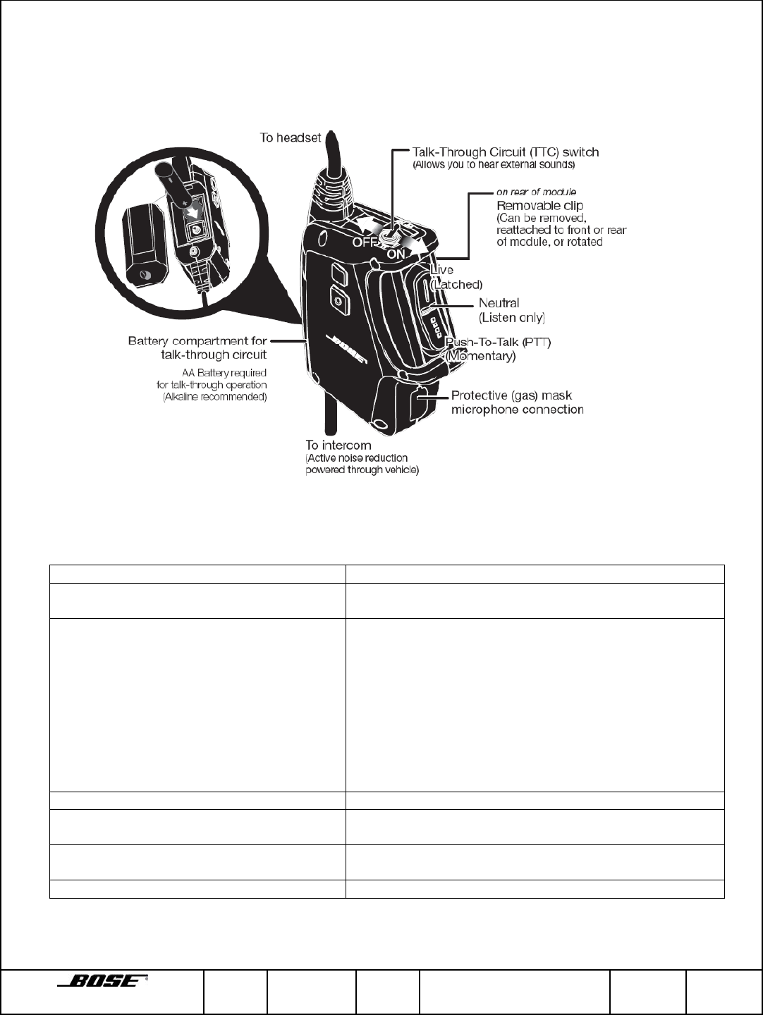
In addition to offering all of the same features as the TTH, the TTH Series
2 has been redesigned for better ergonomics with an integrated
attachment clip.
Figure 2.0c TTH Series 2 Control Module Features
COMPONENT FUNCTION
Microphone Boom and Cable Assembly Transmits user’s voice into intercom or radio
channel
PTT Switch Used when transmitting on and listening to intercom
channel or radio. The latched position allows the
user to communicate on the vehicle intercom.
The OFF (center position allows the user to listen
only.
The Momentary (down) position allows the user to
communicate on the vehicle intercom and the
selected radio. Please note that these function
could vary by intercom. Please consult the intercom
manual.
Vehicle Interface Connector Provides quick-disconnect for operator.
TTC Switch Used to monitor ambient noise environment when
desired.
M42 Gas Mask Microphone Connection Allows M116/G microphone in the M42 gas mask to
be plugged into the headset.
Battery Compartment Contains AA alkaline battery to power TTC.
Framingham, MA 01701-9168 SIZE
A FSCM
32108 CLASS
RF DWG NO. 273139 SHEET
7 of 25 REV.
01D
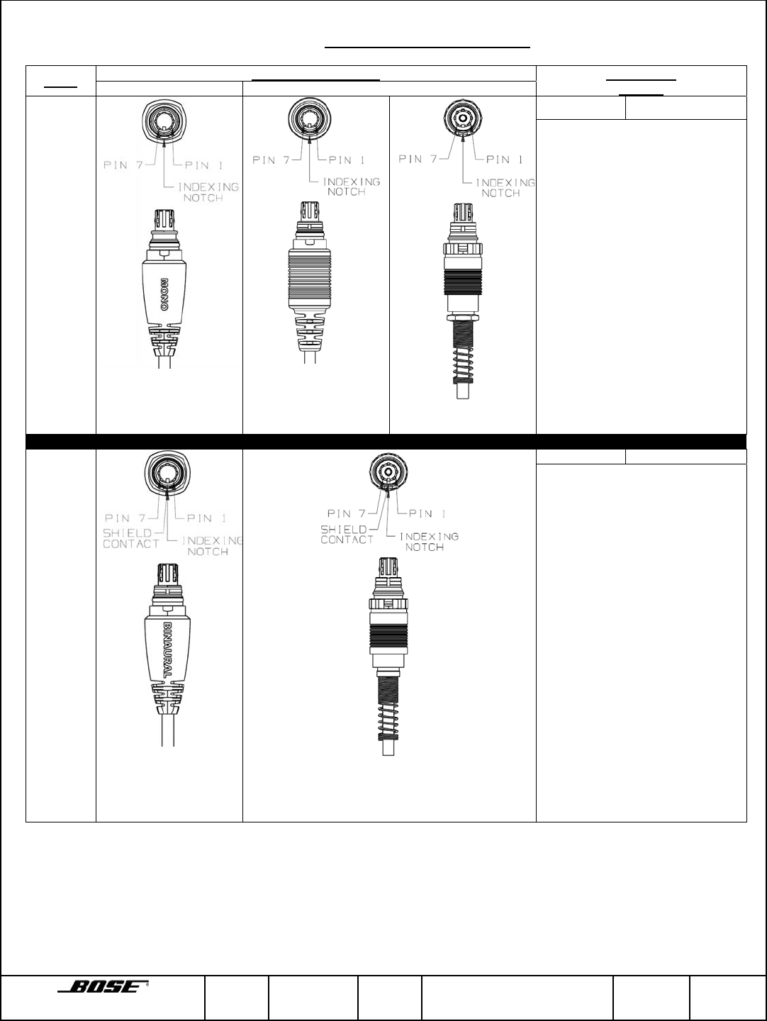
Vehicle Interface Connector
Desc. Physical Appearance Connection
Pin-out
TTH Series 2 TTH
Monaural
Prior to
Pin Function
1
2
3
4
5
6
7
Shield
PTT
Ground
(power and audio)
Boom mic
Ground**
Left/Right earcup
audio
Boom mic
Signal**
Power
Binaural
Pin Function
Shield
Contact
1
2
3
4
5
6
7
Shield
Right earcup
audio
PTT
Ground
(power and audio)
Boom mic
ground**
Left earcup
audio
Boom mic
signal
Power
**Mic ground must be connected to the power/phone ground (pin 3) in the
intercom for the microphone circuit to function.
Framingham, MA 01701-9168 SIZE
A FSCM
32108 CLASS
RF DWG NO. 273139 SHEET
8 of 25 REV.
01D
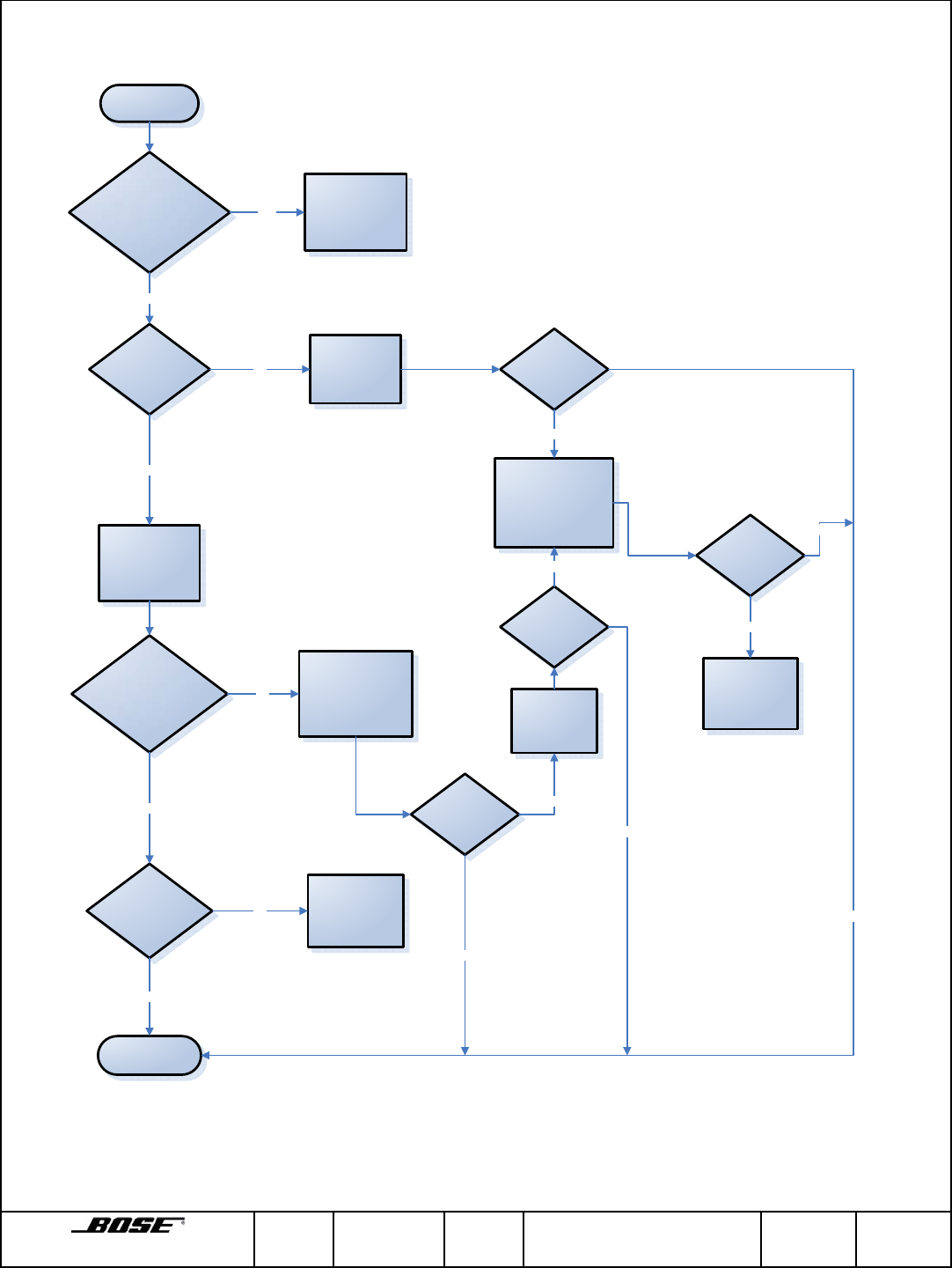
4. HEADSET TROUBLESHOOTING
START
PHYSICAL DAMAGE OR
DETERIORATION PRESENT?
CAN AUDIO BE
HEARD THRU TTC?
IS FAULT STILL
PRESENT?
MICROPHONE
TRANSMISSIONS RECEIVED
BY OTHERS?
CAN AUDIO BE
RECEIVED THRU
EARCUPS?
END
CONNECT HEADSET
TO KNOWN WORKING
INTERCOM/RADIO
REPLACE TTC
BATTERY
(pg 14)
IS FAULT STILL
PRESENT?
IS FAULT STILL
PRESENT?
SUBSTITUTE CABLE /
MICROPHONE ASSEMBLY
WITH KNOWN WORKING
ONE
(pg 13)
REPLACE EARCUP
ASSEMBLY
(pg 13)
ENSURE MICROPHONE
CABLE IS FIRMLY
CONNECTED BY
CHECKING RIBBON
CONNECTORS
(pg 13)
REFER TO HEADSET
INSPECTION TABLE
REPLACE EARCUP
ASSEMBLY
(pg 13)
YES
NO
YES
NO
YES
NO
YES
YES
YES
NO NO
NO
REPLACE BOOM
MICROPHONE
ASSEMBLY
(pg 17)
IS FAULT STILL
PRESENT?
YES
YES
NO
NO

Framingham, MA 01701-9168 SIZE
A FSCM
32108 CLASS
RF DWG NO. 273139 SHEET
9 of 25 REV.
01D
Headset Inspection Table
Component Condition Corrective Measures
Earcup Assembly Check for cracks and other visible damage to the
housing. Replace earcup assembly*
Napeband Check for visible damage. Replace earcup assembly*
Earcushions Check for visible cuts. Check that uniform
pressure does not cause bottoming against
earcup.
Replace earcushions.*
Cloth Scrim in Earcup Check for tears or excessively dirty. Replace scrim*
Cables Check for cuts, kinks, or frayed area on cable. Replace cable/mic assy*
Connectors Check for dents or other physical damage;
Corrosion buildup. Replace cable/mic assy*
Battery Compartment Check for leakage, dents, corrosion buildup or
other physical damage. Replace cable/mic assy*
Boom Microphpone Check for visible damage to microphone
assembly. Replace boom microphone *
TTC Microphones Check for visible damage or blockage of the metal
screens in front of the TTC microphones on the
front of each earcup.
Replace earcup assembly*
* Refer to applicable removal and replacement procedure.
Framingham, MA 01701-9168 SIZE
A FSCM
32108 CLASS
RF DWG NO. 273139 SHEET
10 of 25 REV.
01D
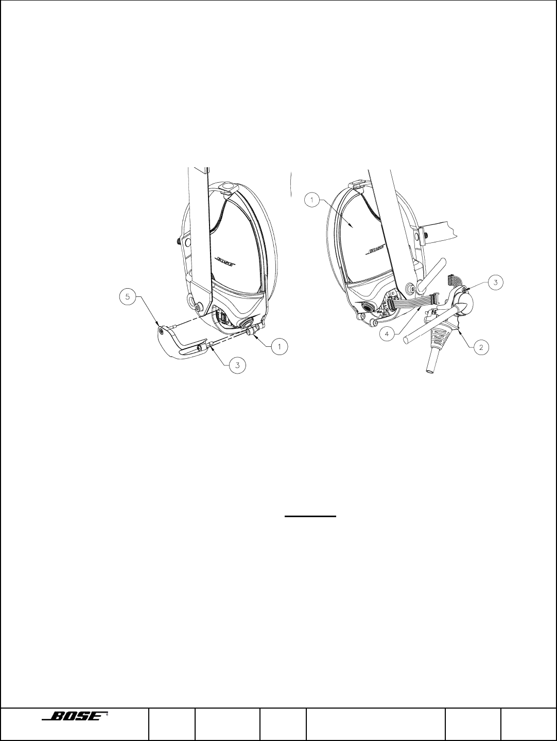
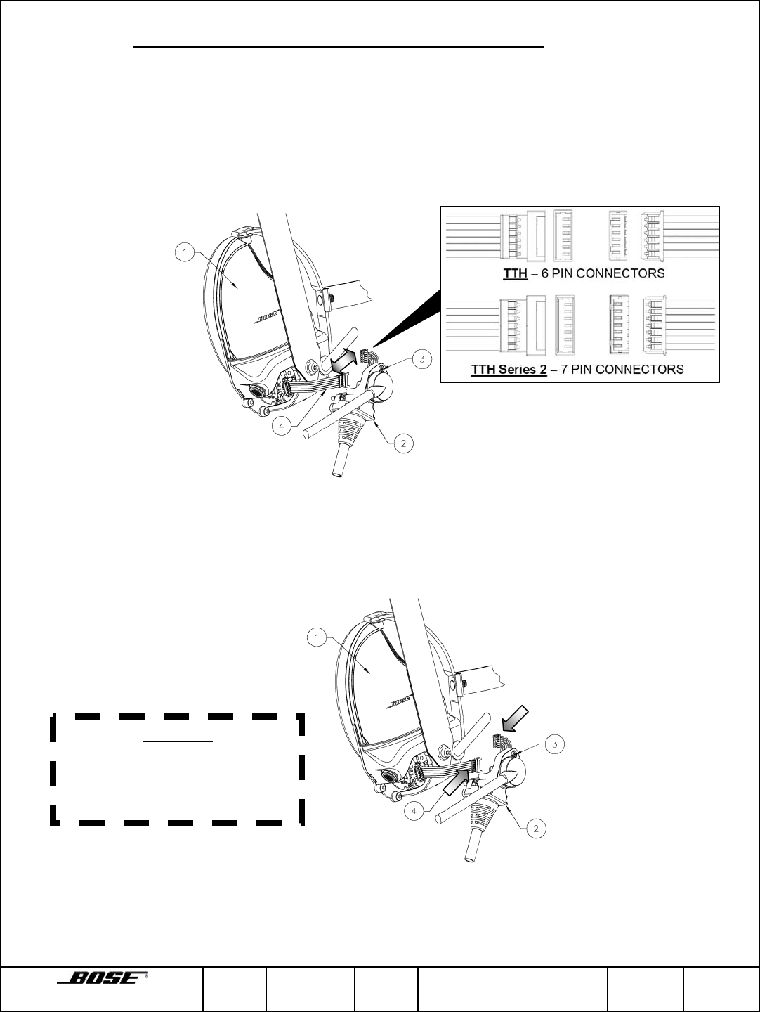
5. HEADSET COMPONENTS REMOVAL AND REPLACEMENT PROCEDURES
5.1 Moving Cable/Microphone Assembly to Opposite Earcup
a. Removal
1. Using cross-tipped screwdriver loosen three captive screws (3) securing
cable/microphone assembly (2) to earcup assembly (1) and the decorative cover
(5) to opposite earcup assembly (1).
2. Unplug connector connecting the cable/microphone assembly (2) to the jumper
cable coming off the earcup printed circuit board and remove the
cable/microphone assembly.
b. Replacement
1. Plug cable connector from the cable/microphone assembly (2) into the jumper
cable (4) coming off the earcup printed circuit board.
CAUTION
Ensure no wires are pinched during reassembly of the electronics cover
to the earcup assembly.
2. Using cross-tipped screwdriver, secure cable/microphone assembly (2) to the
earcup assembly (1).
3. Using cross-tipped screwdriver, secure decorative cover (5) to opposite earcup
assembly.
Framingham, MA 01701-9168 SIZE
A FSCM
32108 CLASS
RF DWG NO. 273139 SHEET
11 of 25 REV.
01D
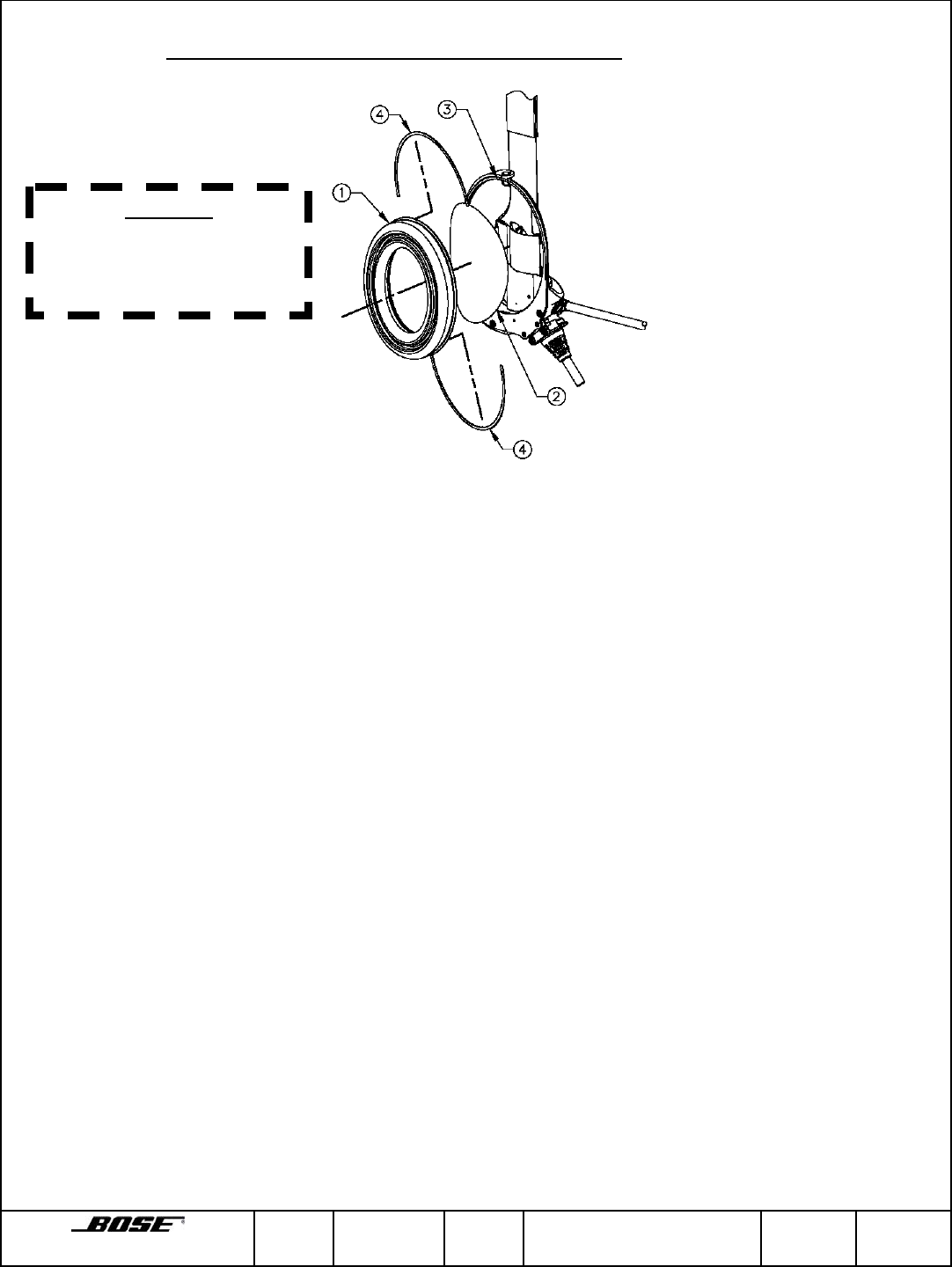
5.2 Earcushion and Scrim Removal and Replacement
Figure 4.2 Earcushion and Scrim Removal and Replacement
a. Removal
1. Remove earcushion (1) from earcup assembly (3) by inserting fingers inside
earcup between scrim (2) and earcushion and firmly pulling out. Remove any
excess tape residue from the earcup surface.
2. Remove scrim (2) after earcushion (1) is removed.
b. Replacement
1. Align scrim (2) and place over screen in earcup assembly (3).
2. Remove and discard release liners (4) from tape on earcushion assembly.
3. Align and set earcushion (1) on earcup assembly (3) and snap in place.
CAUTION
Do not attempt to remove
the earcushion by pulling on
the soft earcushion material.
Framingham, MA 01701-9168 SIZE
A FSCM
32108 CLASS
RF DWG NO. 273139 SHEET
12 of 25 REV.
01D
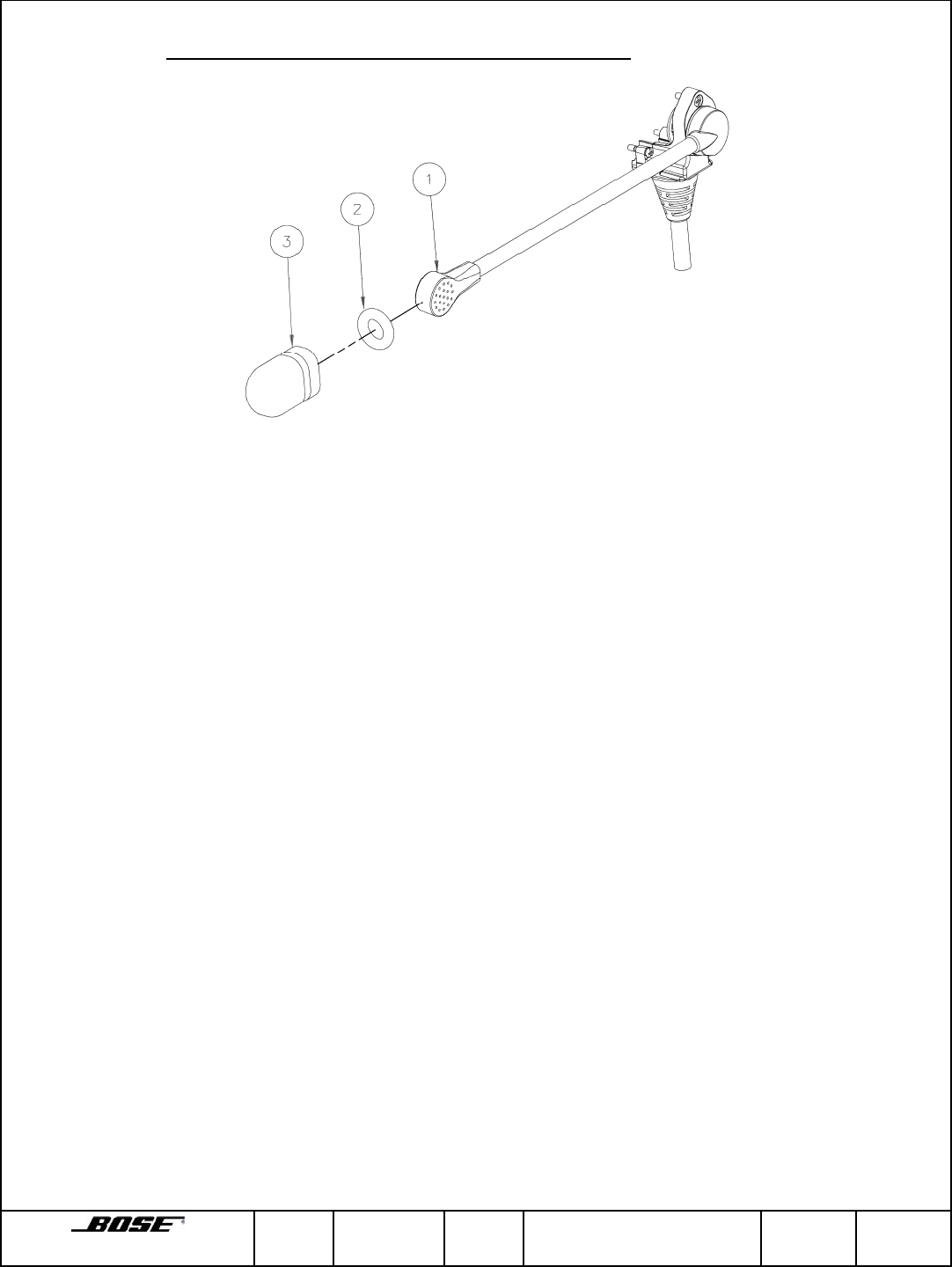
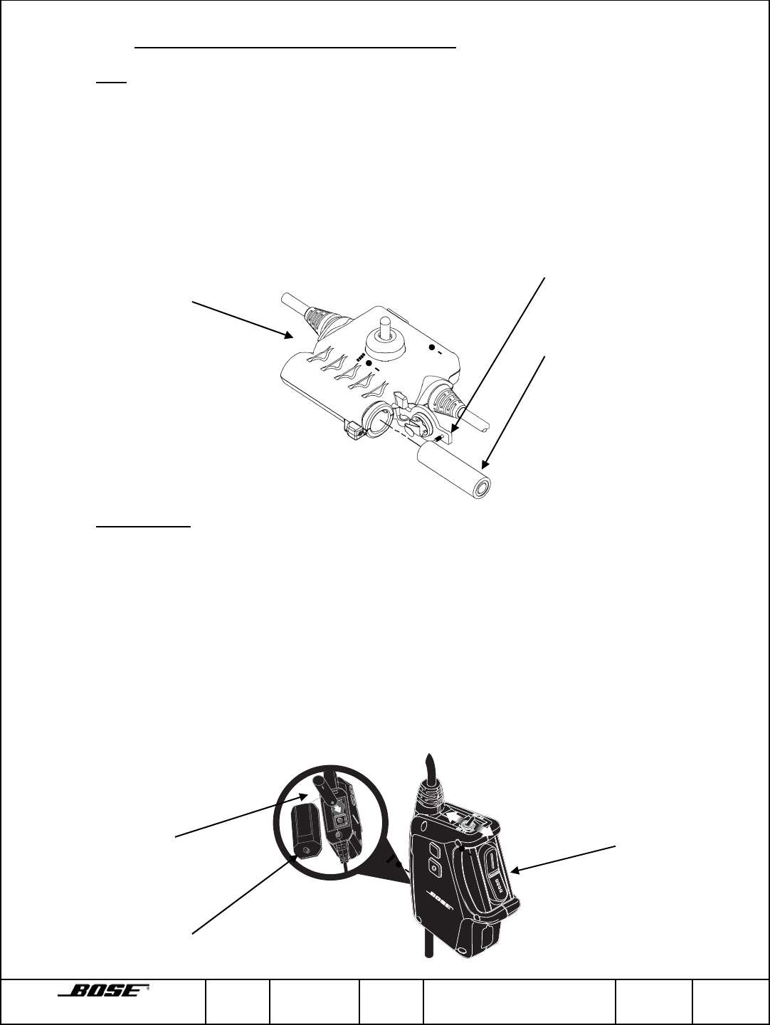
5.3 Windscreen and O-ring Removal and Replacement
Figure 4.3 Windscreens and O-ring Removal and Replacement
a. Removal
1. Grasp O-ring (2) between thumb and forefinger and slide O-ring (2) and
windscreen (3) off microphone (1).
2. Separate O-ring (2) from windscreen (3).
CAUTION
When placing windscreen/O-ring on microphone, be careful not to tear windscreen.
b. Replacement
1. Compress closed end of windscreen (3) and place inside O-ring (2) until O-ring is
midway on windscreen.
2. Slide O-ring (2) with windscreen (3) onto microphone (1) and adjust O-ring until
windscreen is secured.
Framingham, MA 01701-9168 SIZE
A FSCM
32108 CLASS
RF DWG NO. 273139 SHEET
13 of 25 REV.
01D
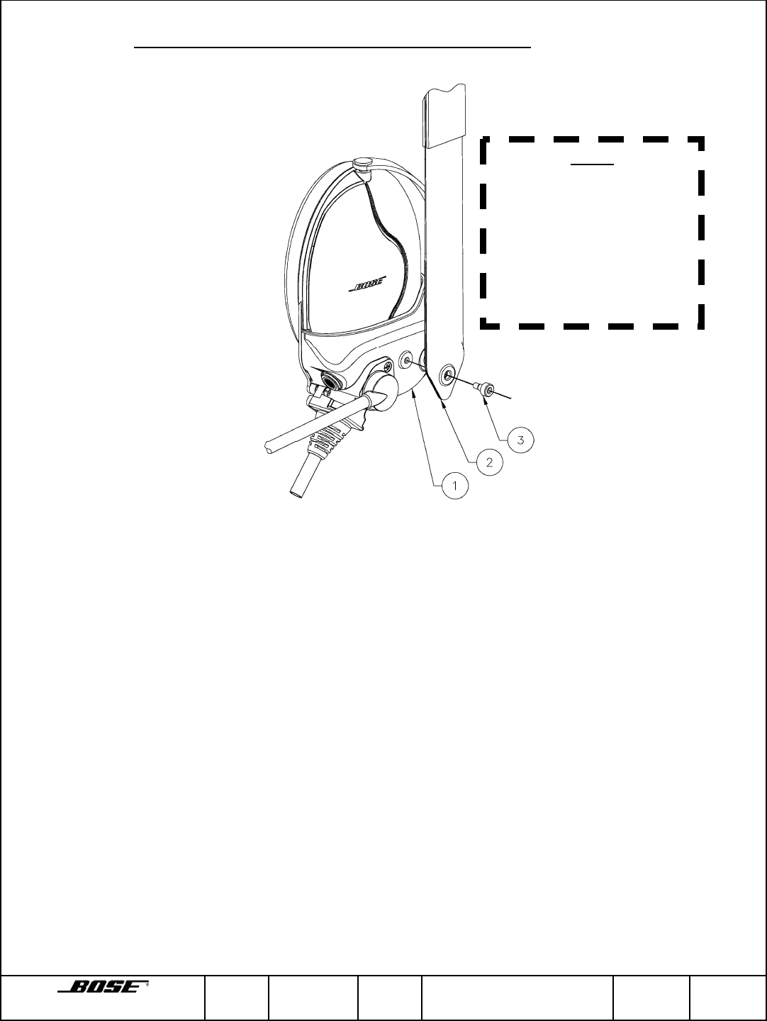
5.4 Overhead Strap Assembly Removal and Replacement
Figure 4.4 Overhead Strap Assembly Removal and Replacement
a. Removal
Using a hex (Allen type) wrench remove screw (3) securing overhead strap (2) to
earcup assembly (1).
b. Replacement
Place screw (3) through opening in end of overhead strap (2) and use a hex (Allen
type) wrench to secure to earcup assembly (1).
NOTE
The overhead strap
assembly consist of two
hook and loop strap
sections, hooks and loops.
When placing a single
strap at a time make sure
the replacing strap is the
same as the one being
r
e
m
o
v
ed
.
Framingham, MA 01701-9168 SIZE
A FSCM
32108 CLASS
RF DWG NO. 273139 SHEET
14 of 25 REV.
01D
5.5 Cable/Microphone Assembly Removal and Replacement
a. Removal
1. Using cross-tipped screwdriver loosen three captive screws (3) securing
cable/microphone assembly (2) to earcup assembly (1). Unplug connector
connecting the cable/microphone assembly (2) to the jumper cable coming off
the earcup printed circuit board and remove the cable/microphone assembly.
b. Replacement
1. Plug cable connector from the cable/microphone assembly (2) into the jumper
cable (4) coming off the earcup printed circuit board.
2. Using cross-tipped screwdriver, secure cable/microphone assembly (2) to the
earcup assembly (1).
CAUTION
Ensure no wires are pinched
during reassembly of the
cable/microphone assembly to
the earcup assembly.
Framingham, MA 01701-9168 SIZE
A FSCM
32108 CLASS
RF DWG NO. 273139 SHEET
15 of 25 REV.
01D
5.6 Alkaline Battery Removal and Replacement
a. TTH Battery Removal and Replacement
1. Using flat-tipped screwdriver, loosen the captive screw on the battery cover and
rotate to open the battery compartment.
2. Remove old battery and insert replacement battery positive end first into the
battery compartment.
3. Close battery cover and tighten screw using flat-tipped screwdriver.
b. TTH Series 2 Battery Removal and Replacement
1. Using flat-tipped screwdriver, loosen the captive screw on the battery cover and
rotate to open the battery compartment. Battery door is connected to the control
module via a stainless steel tether.
2. Remove old battery and insert replacement battery positive end first into the
battery compartment.
3. Close battery cover by inserting the tab on the battery cover into the slot in the
control module and rotating the battery cover closed.
4. Tighten screw using flat-tipped screwdriver.
Captive screw on
battery cover
+
-
Co
n
t
r
o
l M
odu
l
e
Observe Polarity
Captive screw on
battery cover +
-
Control Modu
le
Observe Polarity
Framingham, MA 01701-9168 SIZE
A FSCM
32108 CLASS
RF DWG NO. 273139 SHEET
16 of 25 REV.
01D
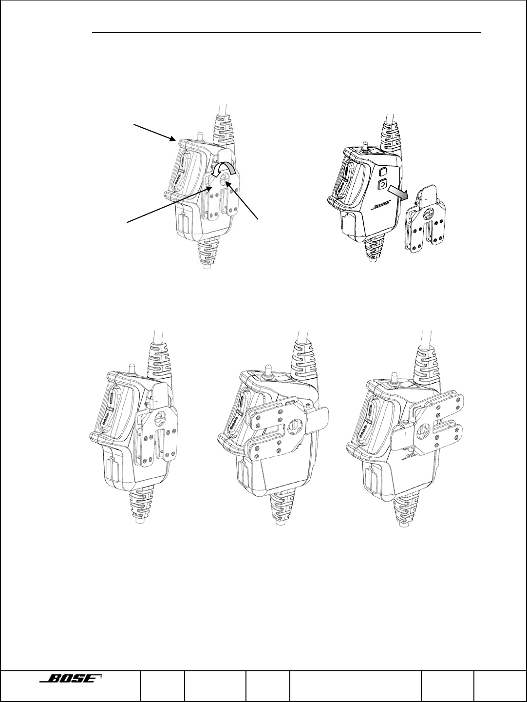
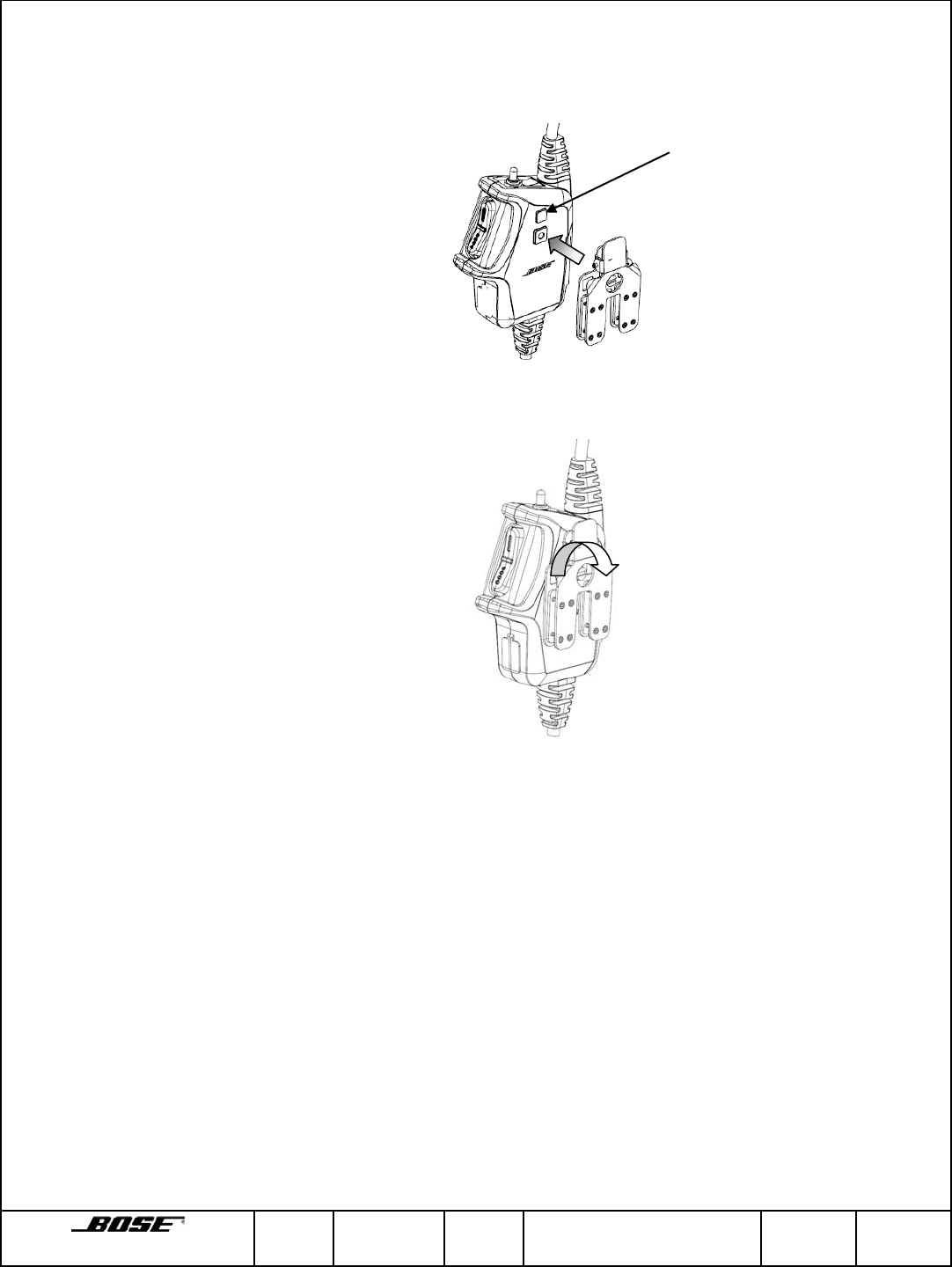
5.7 Attachment Clip Removed, Replacement or Adjustment (TTH Series 2 ONLY)
a. Removal
1. Using a flat-tipped screwdriver loosen the captive screw securing attachment clip
to the control module and remove clip from the control module.
b. Replacement and Adjustment
1. Attachment clip can be rotated into 3 different positions.
Position 1 Position 2 Position 3
Attachment clip
captive screw
Control Module
Attachment
Clip
Framingham, MA 01701-9168 SIZE
A FSCM
32108 CLASS
RF DWG NO. 273139 SHEET
17 of 25 REV.
01D
2. Position attachment clip on the control module in the desired orientation. Rotate
the attachment clip 90 degrees in either direction, lining up the square feature on
the control module with the square hold in the attachment clip.
3. Using flat-tipped screwdriver, secure attachment clip to the control module.
Attachment clip
alignment feature
Framingham, MA 01701-9168 SIZE
A FSCM
32108 CLASS
RF DWG NO. 273139 SHEET
18 of 25 REV.
01D
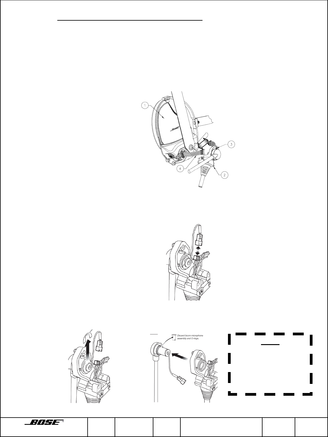
5.8 Boom Microphone Removal and Replacement
a. Removal
1. Using cross-tipped screwdriver loosen three captive screws (3) securing
cable/microphone assembly (2) to earcup assembly (1). Unplug connector
connecting the cable/microphone assembly (2) to the jumper cable coming off
the earcup printed circuit board and remove the cable/microphone assembly.
2. Unplug the 3-pin connector connecting the boom microphone to the cable
assembly.
3. Remove the e-ring securing the boom microphone in place and remove and
discard the boom microphone.
NOTE
Remove o-rings with
microphone assembly.
O-rings may remain in
barrel when
microphone assembly
is removed.
Framingham, MA 01701-9168 SIZE
A FSCM
32108 CLASS
RF DWG NO. 273139 SHEET
19 of 25 REV.
01D
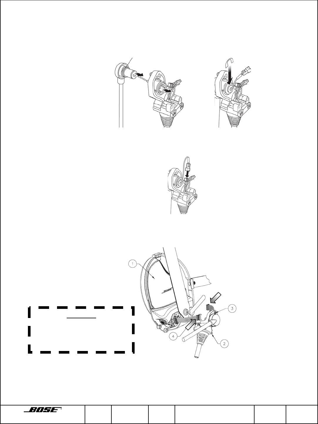
b. Replacement
1. Insert microphone through barrel of the plastic housing. Push replacement
microphone with 2 new o-rings into the barrel of the plastic housing and secure in
place with e-ring.
2. Plug 3-pin connector from the microphone assembly into the mating 3-pin
connector on the cable assembly. Ensure connectors are securely seated.
3. Plug cable connector from the cable/microphone assembly (2) into the jumper
cable (4) coming off the earcup printed circuit board.
4. Using cross-tipped screwdriver, secure cable/microphone assembly (2) to the
earcup assembly (1).
CAUTION
Ensure no wires are pinched
during reassembly of the
cable/microphone assembly to
the earcup assembly.

Framingham, MA 01701-9168 SIZE
A FSCM
32108 CLASS
RF DWG NO. 273139 SHEET
20 of 25 REV.
01D
Appendix A
Additional Technical Information
Framingham, MA 01701-9168 SIZE
A FSCM
32108 CLASS
RF DWG NO. 273139 SHEET
21 of 25 REV.
01D
Voltage Range
The headset shall operate in one of three different modes as a function of the
applied voltage. The operating modes shall be identified as “Unpowered”, “Low
Power” and “Intercom”, and each mode shall be active with the voltage applied at
the power contacts of the vehicle interface connector.
Operating Mode Voltage Range
TTH TTH Series 2
Unpowered 0.0 – 5.8 VDC 0.0 – 13.5V
Unpowered or Low Power 5.8 – 6.1 VDC --
Low Power 6.1 – 11.0 VDC --
Low Power or Intercom 11.0 – 13.5 VDC --
Intercom 13.5 – 32.0 VDC 13.5 – 32.0 VDC
Over Voltage
The headset shall survive and operate without malfunction when a pulse of
duration 100µs and potential 36V above ground is applied to the power line. The
pulse repetition rate shall not exceed 1 pulse every 10ms.
Ripple and noise
The headset shall operate through and reject power supply ripple up to 2.7V
peak to peak from 300 Hz to 4500 Hz. During exposure to ripple, the headset
shall not product any noise greater than 65 dB SPL.
Intercom Mode Operation (Standard Operating Mode)
When operating at Intercom Mode the headset shall have the following current
draw characteristics under any condition, except during turn-on:
Current Draw
TTH TTH Series 2
At least 40ma but less
than 220 mA peak Less than 38mA
peak
In Intercom Mode, the headset shall have the following functional characteristics:
Functional
Characteristics TTH TTH
Series 2
Active ANR 3 3
Selectable Talk-through 3 3
Powered Output Level 3 3
Powered Frequency
Response
3 3
Active microphone
preamplifier output
3Not
Applicable

Framingham, MA 01701-9168 SIZE
A FSCM
32108 CLASS
RF DWG NO. 273139 SHEET
22 of 25 REV.
01D
Low Power Mode Operation
When operating in Low Power Mode the headset shall have the following current
draw characteristics on the head in 85dBA red noise:
Current Draw
TTH TTH Series 2
Less than 16mA RMS
and less than 180mA
peak under any
condition, except
during turn-on
Less than 16mA
peak under any
condition, except
during turn-on
In Low Power Mode, the headset shall have the following functional
characteristics:
Functional
Characteristics TTH TTH
Series 2
Active ANR 3
Selectable Talk-through 3 3
Powered Output Level 3
Powered Frequency
Response
3
Inactive microphone
preamplifier output
3Not Applicable
Unpowered Mode Operation
When operating in Unpowered Mode the headset shall have the following current
draw characteristics on the head in 85dBA red noise:
Current Draw
TTH TTH Series 2
Less than 1mA RMS Less than 1mA RMS
In Unpowered Mode, the headset shall have the following functional
characteristics:
Functional
Characteristics TTH TTH
Series 2
Inactive ANR 3 3
Selectable Talk-through 3 3
Unpowered Output Level 3 3
Unpowered Frequency
Response
3 3
Inactive microphone
preamplifier output
3Not
Applicable

Framingham, MA 01701-9168 SIZE
A FSCM
32108 CLASS
RF DWG NO. 273139 SHEET
23 of 25 REV.
01D
PTT Switch
The PTT switch shall provide the following function at the vehicle interface
connector:
Switch Position Function
Up, latching PTT line (contact #2) connected to ground
(contact #3) through 470±5% ohms (power
dissipation in this resistor is less than 0.1W)
Center, latching PTT line (contact #2) open circuit
Down, momentary PTT line (contact #2) connected to ground
(contact #3) through 10 ohms maximum
The boom microphone output signal shall not be muted or disconnected from the
vehicle interface connector in any PTT mode. The vehicle interface connector
shall conform to the pinouts described in Section 3.0 of this document.
Input Impedance
The headset shall not cause damage to the intercom audio circuits under any
circumstances. The audio input impedance of the headset assembly shall be as
follows:
Power Mode Audio Input Impedance
Intercom and Low Power 500 ± 10% ohms
Unpowered No less than 10 ohms
Insulation resistance
The insulation resistance of the headset assembly between any interconnection
terminals and any exposed metal cover shall not be less than 10 Megaohms.
Dielectric withstanding voltage
The headset assembly shall withstand, without flashover or breakdown, the
application of a 100Vrms alternating potential of commercial line frequency for 10
seconds.
Crosstalk
The headset assembly shall provide at least 60dB of separation between the
transmit (mic) and the receive (audio input) as well as the transmit (mic) and
power lines.

Framingham, MA 01701-9168 SIZE
A FSCM
32108 CLASS
RF DWG NO. 273139 SHEET
24 of 25 REV.
01D
Microphone preamplifier output (TTH only)
This section is only applicable to TTH. The TTH Series 2 product design does
not include an integrated microphone preamplifier output circuit.
TTH ONLY: In the Intercom Mode the boom microphone preamplifier circuit shall
provide an output capable of driving 200mVrms into an unbalanced load of
150±10% ohm AC impedance and not less than 300 ohms DC resistance. The
preamplifier shall provide a gain of 24±1dB with any dynamic microphone. The
preamplifier shall have a flat frequency response between 300 to 4500 Hz.
Harmonic distortion shall be less than 5% for an output of 100mVrms in 24dB
gain mode. The preamplifier shall be bypassed in the Low Power and
Unpowered modes.
Microphone Impedance
The electrical impedance of the microphone at any frequency over the range of
400 to 6000 Hz shall be such that the output voltage shall remain -56±4 dBm @
1kHz re. 103 dBSPL when connected to a 150 ohm load impedance.
Talk-through circuit (TTC)
The headset shall incorporate a talk-through circuit to permit monitoring of the
ambient sound field and direction finding. When mounted on a simulated real
head fixture (mannequin), at 22oC, 50% RH the TTC shall produce gain of 0±
6dB when measured in the 500 Hz octave band and an acoustic frequency
response within 0± 8dB when measured in one octave frequencies between 300
and 4500 Hz and corrected for diffuse field response of the fixture.
The talk-through circuit shall limit direct earcup output to between 86dB(A) SPL
maximum and 72dB(A) minimum with the output corrected for the diffuse field
response of the fixture.
The headset assembly shall accept a number 15A (AA) battery per ANSI C18.1
for operation of the TTC. When exposed to 90 dB, 1kHz noise field with a fresh
battery, the TTC shall provide the following battery life:
TTH TTH Series 2
Battery
life 240 hrs
Minimum 240 hrs
Minimum
Audio Output Level
The headset at 22oC, 50% RH shall product an output level of 106±3dB SPL
corrected for the diffuse fields response of the fixture for a 0± 0.1dBV input audio
signal at 500Hz when in either the Intercom or Low Power Mode. With the
headset in the Unpowered Mode, the output level shall be 94±4dB SPL corrected
for the diffuse field response of the fixture in the octave around 500 Hz for a 0±
0.1dBV input audio signal.

Framingham, MA 01701-9168 SIZE
A FSCM
32108 CLASS
RF DWG NO. 273139 SHEET
25 of 25 REV.
01D
Harmonic Distortion
The harmonic distortion of the earphone assembly in Low Power and Intercom
Modes shall not exceed 5% for a 0± 0.1dBV input at 500 Hz and it shall not
exceed 10% with the input adjusted for an output of 100dB SPL at 500 Hz and
then swept from 300 Hz to 4500 Hz. The harmonic distortion of the earpohone
assembly in Unpowered Mode shall not exceed 5% for a -6± 0.1dBV input at 500
Hz and it shall not exceed 10% with the input adjusted for an output of 94dB SPL
at 500 Hz and then swept from 300 Hz to 4500 Hz.
Talk Through Circuit (TTC)
The headset shall incorporate a talk-through circuit to permit monitoring of the
ambient sound field and direction finding. When mounted on a simulated real
head fixture (mannequin), at 22oC, 50% RH the TTC shall produce gain of 0±
6dB when measured in the 500 Hz octave band and an acoustic frequency
response within 0± 8dB when measured in one octave frequencies between 300
and 4500 Hz and corrected for diffuse field response of the fixture.
The talk-through circuit shall limit direct earcup output to between 86dB(A) SPL
maximum and 72dB(A) minimum with the output corrected for the diffuse field
response of the fixture.
Boom Microphone Sensitivity
The dynamic boom microphone sensitivity shall be -56±4 dBm @ 1kHz re. 103dB
SPL.
