Boston Scientific Neuromodulation SC-5300 SCS Implant System Charger User Manual SCS Dr Covers
Boston Scientific Neuromodulation Corporation SCS Implant System Charger SCS Dr Covers
Contents
- 1. patient system handbook
- 2. patient trial handbook
- 3. manual insert
- 4. physician implant manual
- 5. physician lead manual
physician lead manual
Spinal Cord Stimulation System
LINEAR™ Lead
model SC2108
Lead Extension
model SC3108
Physician Lead Manual
9055095-001 Rev C

Physician Lead Manual
ii ©2003 by Advanced Bionics Corporation. All Rights Reserved.
CAUTION. Investigational device. Limited by federal law to
investigational use.
This device complies with part 15 of the FCC Rules. Operation is
subject to the following two conditions: (1) This device may not
cause harmful interference, and (2) This device must accept any
interference received including interference that may cause
undesired operation.
The Precision System components should be serviced only by
Advanced Bionics. Do not attempt to open or repair any of the
components. Unauthorized opening of or attempts to repair the
components will void the warranty.
Copyright
©2003 by Advanced Bionics Corporation. All Rights Reserved. Any
copying, reproduction or translation of all or part of the contents of
this document without the express written permission of Advanced
Bionics Corporation is strictly forbidden by the provisions of the law
of March 11th, 1957.
Guarantees
Advanced Bionics Corporation reserves the right to modify, without
prior notice, information relating to its products in order to improve
their reliability or operating capacity.
Registered Trademarks
Linear™, BionicNavigator™ and Precision™ are registered trademarks
of Advanced Bionics Corporation. Velcro® is a registered mark of
Velcro Industries, Manchester, New Hampshire. Other brands and
their products are trademarks or registered trademarks of their respec-
tive holders and should be noted as such.

Table of Contents
iii
Table of Contents
Introduction ............................................... 1
Manual Overview ...........................................................1
Product Description ..........................................................1
Lead ....................................................................... 1
Lead Extension .......................................................... 2
Indications for Use ...........................................................3
Contraindications ............................................................ 4
Safety Instructions ...................................... 5
Warnings ......................................................................5
Precautions ....................................................................5
Adverse Effects ............................................................... 6
Instructions for the Physician ...................... 8
Package Contents ...................................... 9
Lead Kit - Model SC 2108 ............................................... 9
Lead Extension Kit - Model SC 3108 .................................. 9
Sterilization and Handling ........................ 10
Sterilization ..................................................................10
Handling .....................................................................10
Storage ....................................................................... 11
Guidelines for Trial-phase Implantation .... 12
Pre-op Instructions ..........................................................12
Lead Placement ............................................................ 13
Connecting the OR Cable Assembly .................................15
Intraoperative Stimulation Testing ......................................18

iv
Physician’s Lead and Extension Manual
OPTION A: Temporary Lead Trial .................................... 18
OPTION B: Permanent Lead Trial ..................................... 20
Removing the Needle .............................................. 20
Anchoring the Lead ..................................................21
Tunneling And Connecting Extension ........................... 22
Connecting to the Trial Stimulator ............. 28
Guidelines for Permanent Implantation .... 30
Percutaneous Lead/Extension Removal ..............................30
Option A. Temporary Lead Removal ...........................30
Option B. Extension Removal ..................................... 31
IPG Implantation ...................................... 32
Tool Assembly .............................................................. 33
Tunneling The Lead ........................................................33
Connecting To the IPG ...................................................37
Dual Lead Connection .............................................. 37
Single Lead Connection ............................................37
Specifications and Technical Data ............. 40
Lead ........................................................................... 40
Lead Extension .............................................................. 41
Registration Information .......................... 42
Technical Service ...................................... 43
Limited Warranty ..................................... 44

Introduction
1
Introduction
Manual Overview
This manual provides basic information for the implantation and use
of the Advanced Bionics® Lead Model SC 2108 and Lead Extension
Model SC 3108. These products are designed to be percutaneously or
surgically implanted for use with the PrecisionTM Spinal Cord Stimu-
lation (SCS) System to aid in the management of chronic intractable
pain. Information on other system components and their operation can
be found in the Physician Systems Handbook.
General surgical guidelines are presented for temporary and perma-
nent implantation of leads and extensions.
Product Description
Lead
The lead functions as a component of the Precision system by deliver-
ing electrical stimulation to the nerve structures in the dorsal aspect of
the spinal cord, resulting in an inhibition of pain sensation.
Model SC 2108 has eight electrodes located near the distal end. Each
electrode is 3 mm in length and is spaced 1 mm from the adjacent
electrode. The lead body is made of medical grade polyurethane with
a stiffer proximal end to aid insertion into the connector. To aid in
intraoperative testing and positioning, a curved stylet is pre-inserted
2
Physician Lead Manual
into the lead. The lead can be connected to either an extension or
directly to an implantable pulse generator (IPG).
Lead Extension
Lead Extension Model SC 3108 is designed to connect the Lead
Model SC 2108 to the Advanced Bionics Precision implantable pulse
generator for spinal cord stimulation. The extension may be added to
Introduction
3
a lead to externalize the lead for a trial phase or to extend a lead when
a permanent IPG is implanted.
Indications for Use
The Lead Model SC 2108, when used in conjunction with Advanced
Bionics External Trial Stimulator Model SC 5100 or IPG Model SC
1100, is indicated for the management of chronic intractable pain of
the trunk and limbs utilizing spinal cord stimulation. The therapy is
generally most effective in patients who suffer neuropathic pain.
Careful patient selection, therefore, is an important factor in achieving
efficacious outcomes.
It is recommended that patients be screened for psychological factors
that could reduce the likelihood of therapeutic success. (Specific
information regarding patient selection is included in the Physician
Systems Handbook.) Most successful outcomes occur with the fol-
lowing:
• Identifiable pathology
• Pain of neuropathic origin

4
Physician Lead Manual
• Psychological screening
• Patient understanding of risks, benefits and limitations,
and a commitment to a successful therapy
• Successful externalized stimulation trial prior to accep-
tance of permanent IPG implantation
Contraindications
Patients contraindicated for permanent SCS therapy are those who:
• do not meet psychological selection criteria
• have failed trial stimulation
• are poor surgical risks
• are pregnant

Safety Instructions
5
Safety Instructions
Warnings
Pregnancy. The safety and/or effectiveness of neurostimulation dur-
ing pregnancy has not been established.
Diathermy. Shortwave, microwave and/or therapeutic ultrasound
diathermy are categorically contraindicated for SCS patients. The
energy generated by diathermy can be transferred through the stimu-
lator system, causing tissue damage at the lead site which may result
in severe injury or death.
Implanted Stimulation Devices. Spinal cord stimulators may
interfere with the operation of implanted sensing stimulators such as
pacemakers or cardioverter defibrillators. The effects of implanted
stimulation devices on neurostimulators is unknown.
Postural Changes. Patients should be advised that changes in pos-
ture or abrupt movements may cause decreases, or uncomfortable or
painful increases in the perceived stimulation level.
Electromagnetic Interference. Strong electromagnetic fields can
potentially turn the stimulator off, or cause uncomfortable or jolting
stimulation. Patients should be counseled to avoid or exercise care
around:
• Theft detectors or security screeners
• Power lines or power generators
• Electric steel furnaces and arc welders
• Large, magnetized stereo speakers
Precautions
MRI. Patients implanted with the Precision SCS system should not be
subjected to MRI. MRI exposure may result in dislodgement of
implanted components, heating of the neurostimulator, damage to the

6
Physician Lead Manual
device electronics and/or voltage induction through the leads and
stimulator causing an uncomfortable or “jolting” sensation.
Medical Devices/Therapies. The following medical therapies or
procedures may turn stimulation off or may cause permanent damage
to the implant, particularly if used in close proximity to the device:
• lithotripsy
• electrocautery
• external defibrillation
• radiation therapy
• ultrasonic scanning
• high-output ultrasound
If any of the above is required by medical necessity, refer to “Instruc-
tions for the Physician” on page 8. Ultimately, however, the device
may need to be explanted as a result of associated failure.
Automobiles and Other Equipment. Patients should not operate
automobiles, other motorized vehicles, or potentially dangerous
machinery/equipment with therapeutic stimulation turned on. Stimu-
lation must be turned off first. Sudden stimulation changes, if they
occur, may distract patients from attentive operation of the vehicle or
equipment.
Adverse Effects
Potential risks are involved with any surgery. In addition to those typ-
ically associated with surgery, possible risks of stimulation system
implantation include:
• Lead migration, resulting in undesirable changes in
stimulation and subsequent reduction in pain relief.
• System failure, which can occur at any time due to ran-
dom failure(s) of the components or the battery. These
events, which may include device failure, lead breakage,

Safety Instructions
7
hardware malfunctions, loose connections, electrical
shorts or open circuits and lead insulation breaches, can
result in ineffective pain control.
• Tissue reaction to implanted materials can occur.
• Possible surgical procedural risks are: infection, cere-
brospinal fluid (CSF) leakage and, although rare, epidu-
ral hemorrhage, seroma, hematoma, and paralysis.
• External sources of electromagnetic interference may
cause the device to malfunction and affect stimulation.
• Exposure to MRI can result in heating of tissue, image
artifacts, induced voltages in the neurostimulator and/or
leads, lead dislodgement.

8
Physician Lead Manual
Instructions for the Physician
Implanted Stimulation Devices. If other implanted devices are
indicated for the patient, careful screening is required to determine if
safe results can be achieved before permanently implementing con-
current electrical therapies.
Postural Changes. Depending on the activity level of the patient,
postural changes may affect stimulation intensity. Instruct patients to
keep the Remote Control at hand at all times, and ensure that they
understand how to adjust stimulation levels.
Medical Devices/Therapies. If the patient is required to undergo
lithotripsy, electrocautery, external defibrillation, radiation therapy,
ultrasonic scanning, or high-output ultrasound:
• Adjust stimulation to its lowest level before the proce-
dure or application, then turn off IPG.
• All equipment, including ground plates and paddles,
must be used as far away from the IPG as possible.
• Every effort should be taken to keep fields, including
current, radiation, or high-output ultrasonic beams,
away from the IPG.
• Equipment should be set to the lowest energy setting
clinically indicated.
• Instruct patients to confirm IPG functionality following
treatment by turning on the IPG and gradually increas-
ing stimulation to the desired level.

Package Contents
9
Package Contents
Lead Kit - Model SC 2108
(1) Lead
(1) Curved Stylet (pre-loaded in Lead)
(1) Straight Stylet
(2) Suture Sleeves
(1) Insertion Needle
(1) Lead Blank
(1) OR Cable Assembly
(2) Lead Position Labels—left and right (non-sterile)
(1) Manual
(1) Product Registration Form
(1) Temporary Patient Identification Card
Lead Extension Kit - Model SC 3108
(1) Lead Extension
(1) Skin Marker
(1) Hex Torque Wrench
(1) Tunneling Tool Assembly
(1) Manual
(1) Product Registration Form
(1) Temporary Patient Identification Card

10
Physician Lead Manual
Sterilization and Handling
Sterilization
The Advanced Bionics Lead Model SC 2108 and Lead Extension
Model SC 3108 and accessories (except for the Lead Position Labels)
were sterilized with ethylene oxide prior to shipment. Red lines on the
green tape located near the bottom of the inner tray cover indicates
exposure to the sterilization process.
Inspect the condition of the sterilization indicator and the sterile pack-
age before opening the package and using the contents. Do not use the
contents if the indicator lines are not red, if the package is broken or
torn, or if contamination is suspected because of a defective sterile
package seal.
• Do not use any component that shows signs of damage.
• Do not resterilize the package or the contents. Obtain a
sterile package from Advanced Bionics.
• Do not use if “Use Before” date is exceeded.
Note: The lead, lead extension and accessories are intended for
single use only.
Handling
The lead is designed to perform in the hostile environment of the
human body. Care must be taken to avoid damaging the lead with
sharp instruments or excessive force during surgery. The following
guidelines will help to ensure the longevity of components:
• Do not sharply bend or kink the lead or extension.
• Do not tie suture(s) directly to the lead or extension
body; use the provided suture sleeves.
• Avoid forcing the lead into the epidural space by care-
fully clearing a path using the lead blank.

Sterilization and Handling
11
• Avoid pulling an implanted lead taut; provide a stress
relief loop at the insertion site to minimize tension on
the lead.
• Avoid handling the lead with sharp instruments; use
only rubber-tipped forceps.
• Take care when using sharp instruments such as hemo-
stats or scalpels to prevent damaging the lead.
• Wipe off any body fluids from the lead connector end
before connecting it to any other component. Fluid con-
tamination of these connections could compromise the
integrity of the stimulation circuit.
• Wipe off any body fluids from the stylet before inserting
or reinserting it into the lead.
Storage
Store components between 5 °C and 40 °C (41 °F–104 °F) in an area
where they are not exposed to liquids or excessive moisture. Temper-
atures outside of the stated range can cause damage.
12
Physician Lead Manual
Guidelines for Trial-phase Implantation
This section details the recommended procedures for trial-phase tem-
porary implantation of the lead.
Pre-op Instructions
• Check that the sterile package is intact. (See “Steriliza-
tion” on page 10.)
• Ensure that a Trial Stimulator and Patient Trial Kit are
available for use following lead placement. Install a new
6 volt battery (included in the Patient Trial Kit) in the
Trial Stimulator.
• Be sure the Trial Stimulator and Remote Control stimu-
lation settings have been reset. Refer to the IPG manual
for links and resets.
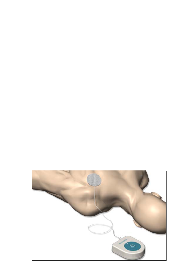
• If monopolar testing is anticipated, place the monopolar/
indifferent electrode (available separately) on the
patient’s shoulder or leg and run the cable to the Trial
Stimulator testing site before the patient is prepped and
draped.
Guidelines for Trial-phase Implantation
13
Lead Placement
Note: Fluoroscopic evaluation of the lead position during this
procedure will aid the physician in achieving an optimum pain
coverage location, and is recommended.
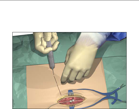
1. Position, prep and drape the patient in the usual accepted manner.
Inject a local anesthetic at the needle insertion site.
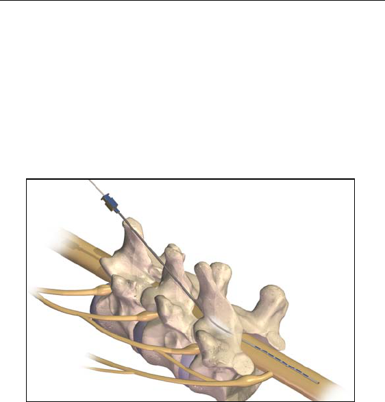
2. Insert the needle into the epidural space with the opening facing
up using an angle of 45° or less.
Use only the insertion needle provided in the Lead Kit. Other
needles may damage the lead. The stamped number on the
needle hub corresponds to the orientation of the bevel,
which must face up. Turning the bevel ventral (down) may
result in lead damage. An angle of more than 45º increases
the risk of lead damage.
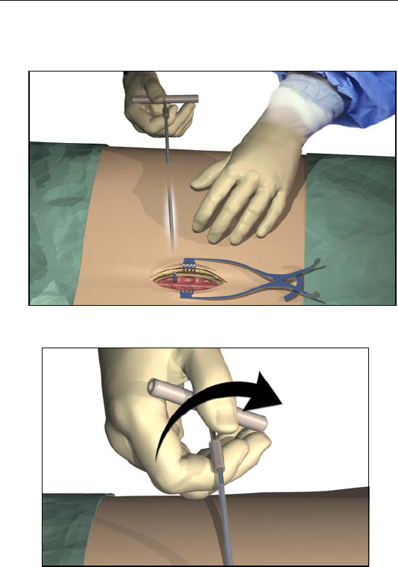
3. Remove the needle stylet and verify entry into the epidural space
using the standard technique.
14
Physician Lead Manual
4. OPTIONAL. Under fluoroscopic guidance, insert the lead blank
through the needle and into the epidural space. Advance the lead
blank to the target location, then withdraw the blank.
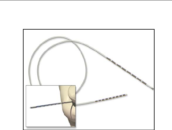
5. Slowly insert the lead, with stylet, through the needle (lead stylet
should extend completely to the tip of the lead).
6. Advance the lead to the appropriate vertebral level using fluoro-
scopic guidance. A sufficient length of lead (i.e., at least 10 cm,
or approximately three vertebrae) aids in lead stabilization.
To facilitate advancement and placement, the lead body may be
rotated.

Guidelines for Trial-phase Implantation
15
Connecting the OR Cable Assembly
The OR cable extension is designed for temporary connection to the
OR cable to facilitate stimulation testing outside of the sterile field.
After stimulation testing, the cable extension is typically removed and
the OR cable is connected directly to the Trial Stimulator for use dur-
ing the trial phase.
Do not immerse the OR cable connector or plug in water or
other liquids. The OR Cable Assembly is intended for one-
time only use; do not resterilize.
1. If two leads are being implanted, wrap the non-sterile 1-L and 2-
R labels around the cables at the Trial Stimulator to identify lead
connections.
2. Verify that the Trial Stimulator is off.
Always turn the Trial Stimulator off before connecting or
disconnecting the Cable Assemblies.
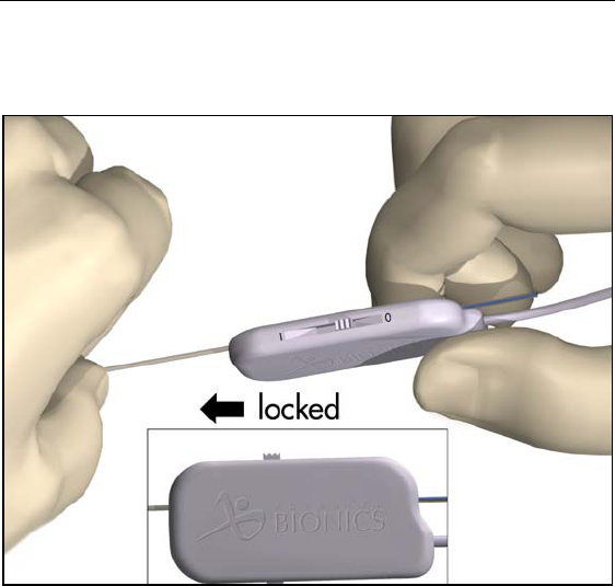
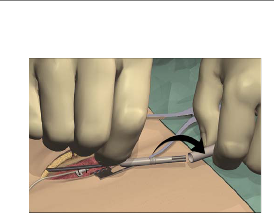
3. Check that the locking lever on the OR cable connector is in the
open position (0).
4. Slide the proximal end of the lead, with stylet, into the open port
on the OR cable connector.
16
Physician Lead Manual
5. Push the end of the lead into the port until it stops. Hold the lead
in place while sliding the locking lever to the “1” (locked) posi-
tion.
Note: Once the lead is secured in the connector, the stylet can be
manipulated in, but not removed from, the lead.
Guidelines for Trial-phase Implantation
17
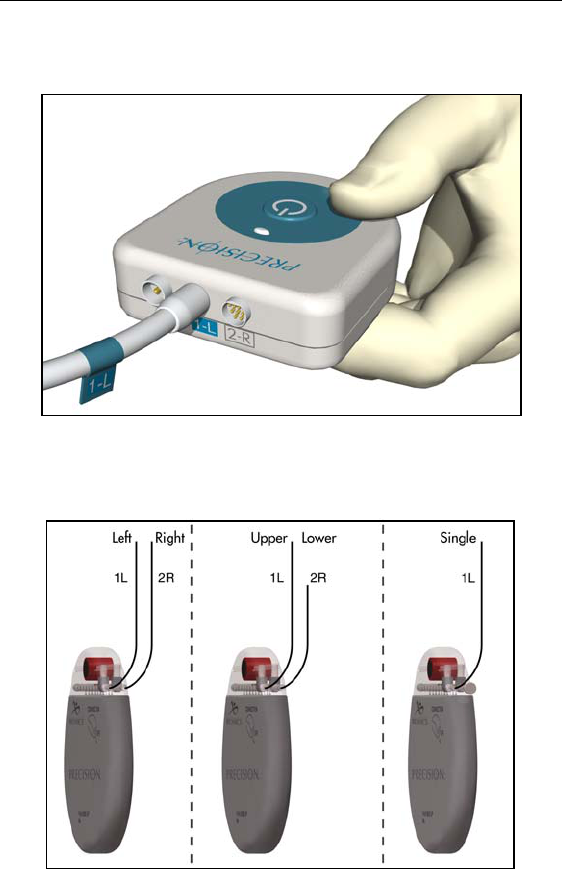
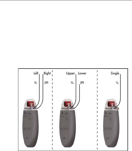
6. Plug the OR Cable Assembly into the Trial Stimulator socket(s)
labeled 1-L (left) and 2-R (right).
Superior (upper or left) leads connect to socket 1-L. Inferior
(lower or right) leads connect to socket 2-R. If only a single lead
is being used, connect it to 1-L.

18
Physician Lead Manual
Intraoperative Stimulation Testing
Note: The following steps are for procedural reference only. Please
refer to the Physician Systems Handbook for detailed
stimulation testing procedures and guidelines.
1. Test various electrode configurations to obtain paresthesia.
Note: If lead repositioning is necessary, turn stimulation off before
proceeding.
2. When the desired paresthesia is achieved:
• turn the Trial Stimulator off
• unlock each OR cable connector and disconnect from
the lead(s)
• slowly withdraw the stylet(s)
3. Record the lead position by capturing a fluoroscopic image to be
sure the leads have not moved. Retest if necessary. The image
can also be used for a position comparison at closure to ensure
that the leads did not move.
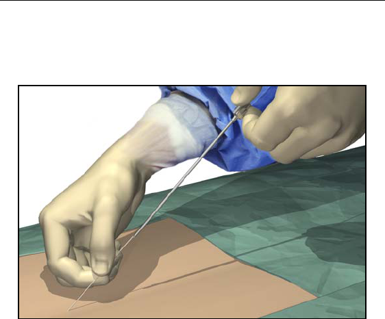
OPTION A: Temporary Lead Trial
1. Hold the lead distal to the needle hub to maintain lead position
during needle removal.
2. Carefully withdraw the insertion needle from the epidural space
by slowly pulling the needle up towards the proximal end of the
lead.
3. Continue to pull the needle back approximately one centimeter at
a time until the needle tip is exposed.
Guidelines for Trial-phase Implantation
19
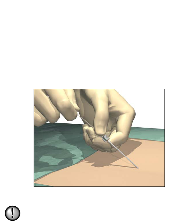
4. Once the needle tip is exposed, hold the lead as close to the per-
cutaneous exit site as possible, then carefully pull the needle
completely from the lead.
5. If desired, a small suture may be used to close the wound and sta-
bilize the lead. Place and tape a stress relief loop and dress the
wound.
6. Continue with “Connecting to the Trial Stimulator” on page 28.
20
Physician Lead Manual
OPTION B: Permanent Lead Trial
Removing the Needle
1. Cut down around the needle to access the supraspinous ligament.
2. Hold the lead distal to the needle hub to maintain lead position
during needle removal.
3. Carefully withdraw the insertion needle from the epidural space
by slowly pulling the needle up towards the proximal end of the
lead.
4. Continue to pull the needle back approximately one centimeter at
a time until the needle tip is exposed.
Guidelines for Trial-phase Implantation
21
5. Once the needle tip is exposed, hold the lead as close to the tip as
possible, then carefully pull the needle completely from the lead.
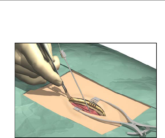
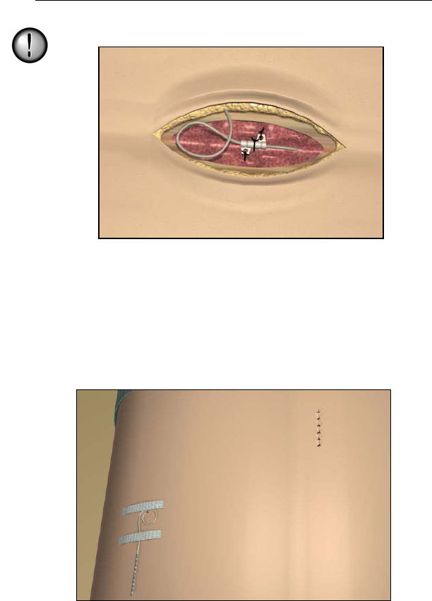
Anchoring the Lead
1. Place a suture through the supraspinous ligament or deep fascial
tissue.
2. Slide a suture sleeve over the lead and down to the supraspinous
ligament.
3. Ligate the sleeve onto the lead by tying a 2-0 silk or other nonab-
sorbable suture around the center groove of the sleeve to prevent
sliding.
Do not use polypropylene sutures as they may damage the
suture sleeve. Do not suture directly onto the lead or use a
hemostat on the lead body. This may damage the lead
insulation.
22
Physician Lead Manual
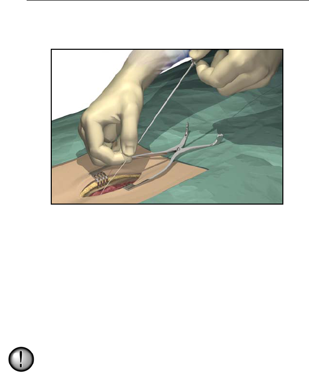
4. Suture the sleeve to the supraspinous ligament or deep fascia
through the suture sleeve holes.
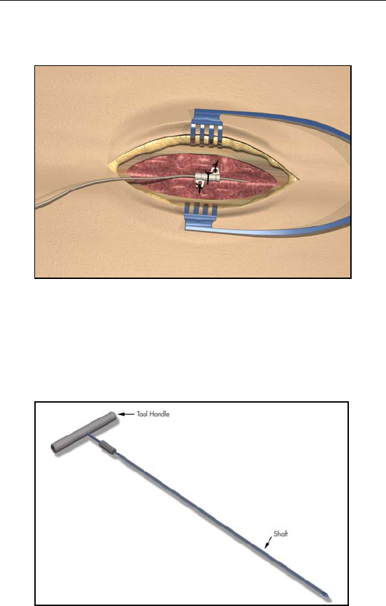
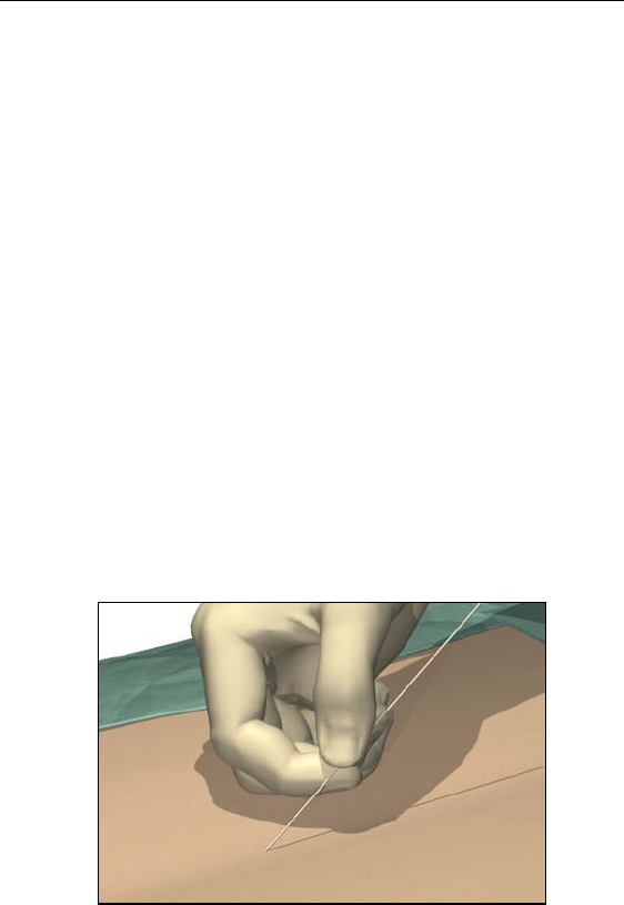
Tunneling And Connecting Extension
A tunneling tool and straw are provided with the Lead Extension Kit
to facilitate percutaneous tunneling of the lead or extension.
• Attach the tunneling tool handle to the shaft by turning
the locking mechanism clockwise.
Guidelines for Trial-phase Implantation
23
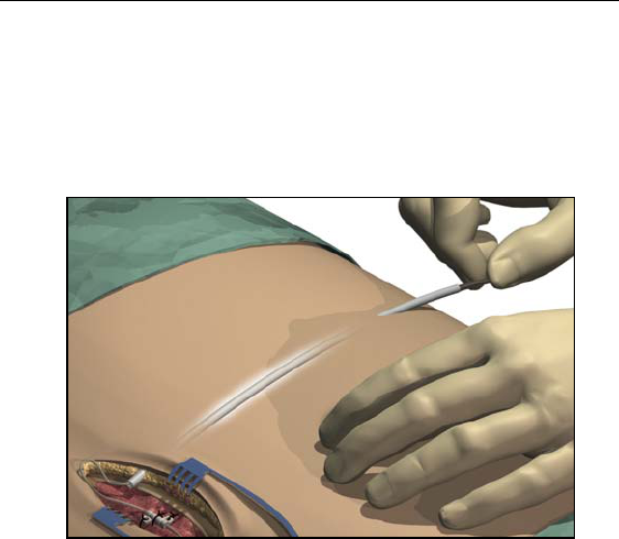
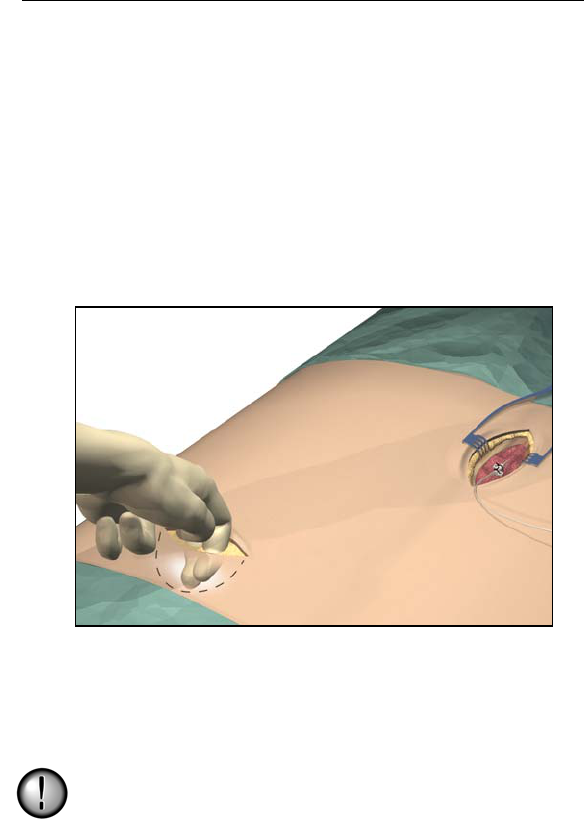
1. Mark the desired route of the tunnel.
2. Administer the appropriate local anesthetic along the tunneling
path.
3. Make a small incision at the desired exit site.
24
Physician Lead Manual
4. Create a subcutaneous tunnel from the exit site to the midline
incision until the straw is visible and accessible at the exit point.
5. Unscrew and remove the tool handle.
Guidelines for Trial-phase Implantation
25
6. Grasp the tip of the tool with one hand while holding the straw in
place with the other hand. Pull the tunneling tool shaft out
through the straw.
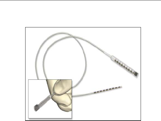
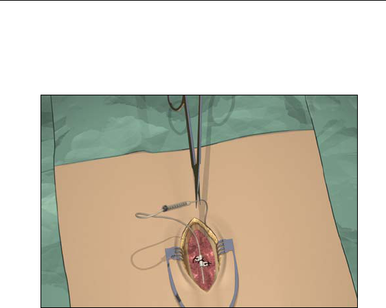
7. Push the lead or extension proximal ends through the straw, then
withdraw the straw.
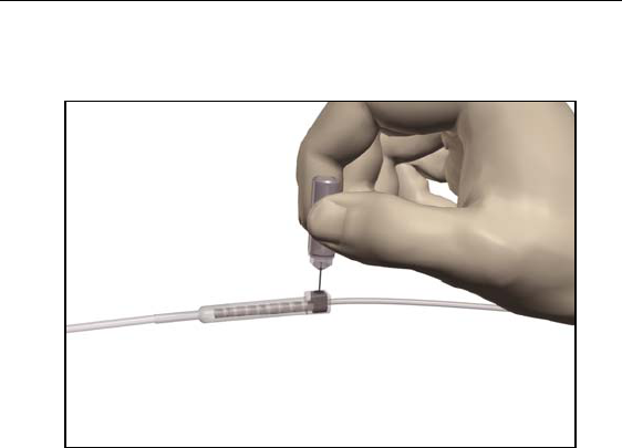
8. Wipe clean the proximal end of the lead, then insert the proximal
end into the extension connector until it stops and the last contact
disappears.
Note: If there appears to be an obstruction, use the torque wrench to
loosen (counterclockwise) the setscrew and/or gently rotate
the lead to help advance the proximal end.
26
Physician Lead Manual
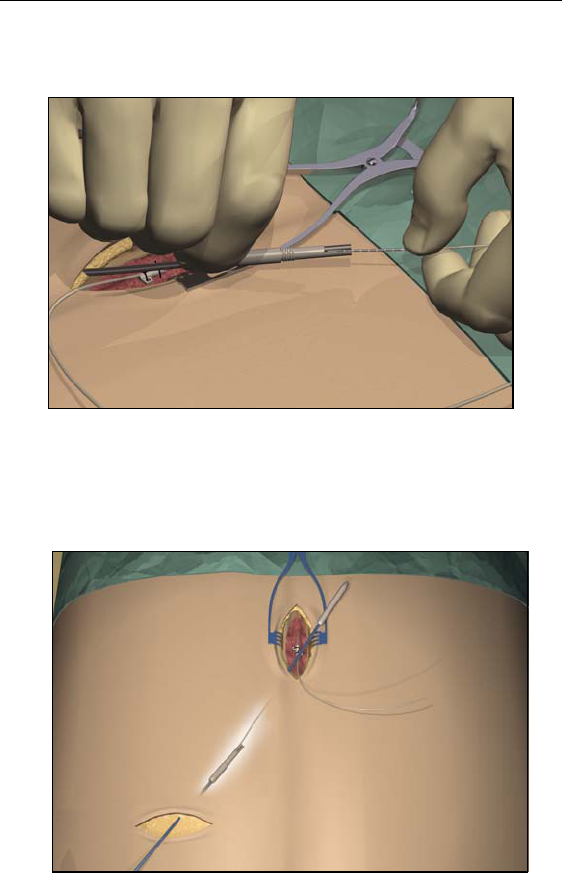
9. Using the torque wrench supplied, turn the extension connector
setscrew clockwise until it clicks, indicating lock.
Note: • Ensure the wrench is fully seated in the setscrew before
tightening.
•The wrench is torque-limited and cannot be overtightened.
10. Form an appropriately-sized pocket using blunt dissection on
either side of midline for coiled excess lead and extension con-
nectors.
11. Place a small loop at the lead for slack. If necessary, loosely tie a
suture around the lead-loop, but do not tighten onto the lead.
Guidelines for Trial-phase Implantation
27
Tightening sutures directly on the lead can damage the lead.
12. Carefully remove excess slack by gently pulling the extensions
from the exit wound.
13. Close the midline incision.
14. If desired, a small suture may be used to close the exit wound of
the extension. Place and tape a stress relief loop and dress the
wound.
28
Physician Lead Manual
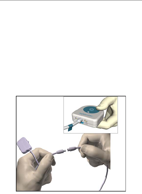
Connecting to the Trial Stimulator
1. Wipe fluids off the exposed lead connections.
2. Disconnect and discard the excess OR cable extension, unless
extra length is needed for trial use.
3. Connect the OR cable(s) to the lead(s) or lead extensions: Slide
the locking lever to “0,” fully insert the end of the extension into
the port, slide the locking lever to “1.”
4. Connect the cable labeled 1-L to the upper or left lead, and the
cable labeled 2-R to the lower or right lead. Labels are provided.
5. Connect the right and left-sided OR cables to the Trial Stimula-
tor, referencing the position labels previously fixed to the cables.
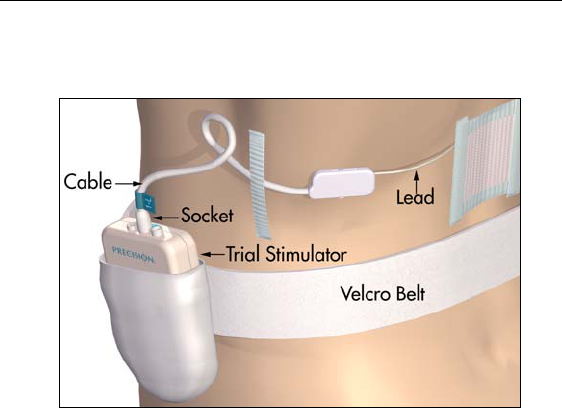
Connecting to the Trial Stimulator
29
6. Fit the Velcro® belt to the patient, cut off the excess length, and
place the Trial Stimulator in the belt pocket.
30
Physician Lead Manual
Guidelines for Permanent Implantation
This section details the procedures for
• tunneling the lead/extension as part of an IPG implant
• connection of lead/extension to the IPG
The Tunneling Tool Assembly used in this procedure is provided with
the Precision device as part of the IPG Kit.
Percutaneous Lead/Extension Removal
Before revising a trial system for chronic stimulation, the exposed
portion of the lead or extension must be removed. The method chosen
from the choices below will depend upon how the patient was pre-
pared for the trial phase.
Remove bandages and properly cleanse the exit site.
Option A. Temporary Lead Removal
1. Clip sutures if used to secure the trial lead(s) in place.
2. Remove the lead(s) completely and discard.
Guidelines for Permanent Implantation
31
Option B. Extension Removal
1. Open the midline incision to expose the lead and connector.
2. Cut the lead extension at the connector.
3. Pull the lead extension through the tunnel and away from body at
the externalized site.
4. Loosen the connector setscrew using the torque wrench provided.
Disconnect and remove the connector.
Note: Connect a new lead extension, if necessary, to reach the
selected IPG site.
32
Physician Lead Manual
IPG Implantation
1. Ensure that the area surrounding the lead entry site is incised to a
dimension that will accommodate the tunneling tool. Check that
the lead is securely sutured with the suture sleeve.
2. Select and mark the intended IPG site several inches away from
the previously externalized leads, and create an incision at the top
of the site.
3. Create a subcutaneous pocket no larger than the IPG outline at a
depth of up to 3/4 inch (2.0 cm) from the surface.
Note: • Using the template will help guide the correct pocket sizing.
It is important to keep the pocket small to reduce the
chances of patient twiddling and IPG flipping afforded by
larger pockets.
•Implant charging frequency or time will increase with
pocket depths greater than 3/4 inch (2.0 cm), and could
become ineffective at greater depths.
IPG Implantation
33
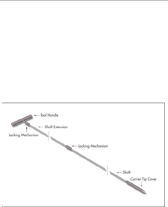
Tool Assembly
The tunneling tool provided with the IPG includes a shaft extender to
be used for up to two leads (with or without extensions).
1. Attach the handle to the tunneling tool shaft by turning the lock-
ing mechanism clockwise.
Note: For more length, attach the shaft extension to the handle, and
then attach the carrier shaft.
2. Thread the tip cover onto the tunneling tool and tighten by turn-
ing clockwise.
Tunneling The Lead
1. Mark the desired route of the tunnel.
2. Administer the appropriate local anesthetic along the tunneling
path.
34
Physician Lead Manual
Note: Check that the tunneling tool tip is securely threaded onto the
carrier.
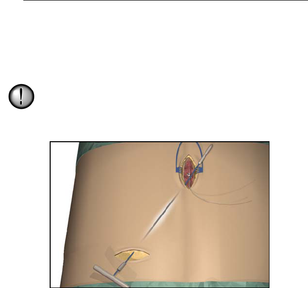
3. OPTIONAL. If necessary, bend the tool shaft to conform to the
patient’s body.
Do not bend locking joints.
4. Create a subcutaneous tunnel from the IPG site to the midline
incision.
Note: Deep tunneling is not recommended.
IPG Implantation
35
5. Once the tunneling tip is completely exposed at midline, press it
toward the shaft and turn it counterclockwise to remove it for
access to the carrier.
Note: You may feel the tip slide back before the cover begins to
unscrew.
36
Physician Lead Manual
6. Carefully position each lead or extension into the carrier shaft
and press the lead/extension into the groove.
Note: If necessary, swivel the carrier by pulling it away from the
handle and turning it to get better access to the cavities.
7. Gently pull the tunneling tool back through the tunnel.
IPG Implantation
37
8. Gently lift the lead(s) out of the locking groove(s).
9. Wipe off any fluids from the proximal end of the lead(s).
Connecting To the IPG
Before implanting the IPG, refer to the IPG Implant Manual.
Dual Lead Connection
• Superior (upper or left) leads connect to IPG port 1-L.
• Inferior (lower or right) leads connect to IPG port 2-R.
Single Lead Connection
• Connect a single lead to IPG port 1-L.
• Plug port 2-R with the connector plug supplied in the
IPG Kit.
38
Physician Lead Manual
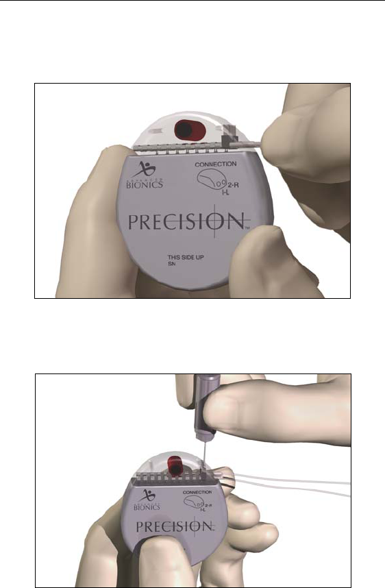
1. Fully insert the lead(s) into the IPG port(s). When the lead is
properly inserted, the lead will stop and the retention ring will be
located under the setscrew.
2. Pass the torque wrench through the slit in the septum located on
the top of the IPG header and tighten both set screws, one at a
time, until the torque wrench “clicks,” indicating lock.

IPG Implantation
39
Note: • If the connector plug is used in port 2-R, it is still necessary
to tighten the setscrew as described.
•The wrench is torque-limited and cannot be overtightened.
•Ensure that the lead is fully inserted before tightening the
setscrew to prevent lead damage.
3. Place the IPG in the subcutaneous pocket with “This Side Up”
facing anterior towards the skin.
4. Coil excess lead or extension under the IPG.
Note: To confirm good connections, check impedances.
5. Secure the IPG in the pocket by suturing through the holes in the
connector.
6. Close and dress the wound(s).

40
Physician Lead Manual
Specifications and Technical Data
Lead
Part Specifications
Model Number SC 2108
Lead Lengths 30, 50, 70 cm
Lead Shape In-line
Lead Diameter 1.3 mm
Number of Electrodes 8
Electrode Length 3 mm
Electrode Spacing 1 mm
Contact Material Platinum/Iridium
Insulation Material Polyurethane
Conductor Material MP35N
Conductor Resistance < 7 Ohms

Specifications and Technical Data
41
Lead Extension
Part Specifications
Model Number SC 3108
Extension Lengths 15, 25 cm
Extension Diameter 1.3 mm
Number of Contacts 8
Contact Material Platinum/Iridium, MP35N, Stainless Steel
Insulation Material Polyurethane, Silicone
Conductor Material MP35N
Conductor Resistance < 10 Ohms

42
Physician Lead Manual
Registration Information
In accordance with international practice and regulatory legislation in
some countries, a registration form is packed with each Advanced
Bionics Corporation lead/lead extension.
The purpose of this form is to maintain traceability of all products and
to secure warranty rights. It also allows the institution involved in the
evaluation or replacement of a specific implanted lead, accessory or
device to gain quick access to pertinent data from the manufacturer.
Fill out the registration form included in the package contents. Return
one copy to Advanced Bionics, keep one copy for patient records, and
provide one copy to the patient and physician.
Advanced Bionics Corporation
25129 Rye Canyon Loop
Valencia, California 91355
Attention: Customer Service Department

Technical Service
43
Technical Service
Advanced Bionics Corporation has highly trained service profession-
als located worldwide to assist you. The Technical Service Depart-
ment is available to provide technical consultation 24 hours a day.
In North America please call (866) 566-8913 to speak to a representa-
tive.

44
Physician Lead Manual
Limited Warranty
Advanced Bionics® Corporation warrants to the patient that the Lin-
ear Lead, Model SC 2108, and Extension, Model 3108, are free from
defects in workmanship and materials for a period of one (1) year
from the date of implantation.
A Lead or Extension that fails to function within normal tolerances
within (1) year from the date of surgery is covered under this Limited
Warranty. The liability of Advanced Bionics® under this warranty
shall be limited to: (a) replacement with a functionally equivalent
Lead or Extension; or (b) full credit equal to the original purchase
price to be applied towards the purchase of a new Lead or Extension.
Product claims under Advanced Bionics® Limited Warranty are sub-
ject to the following conditions and limitations:
1. The product registration card must be completed and returned to
Advanced Bionics® within 30 days of surgery in order to obtain
warranty rights.
2. The Lead or Extension must be returned to Advanced Bionics®
(or authorized agent) within 30 days of malfunction or discovery
of defect, and shall be the property of Advanced Bionics®.
3. The Lead or Extension must be implanted prior to the “use
before” date.
4. Failure of the Lead or Extension must be confirmed by Advanced
Bionics®. This warranty specifically excludes defects or malfunc-
tions caused by: (a) fire, floods, lightning, natural disasters, water
damage and other calamities commonly defined as “Acts of
God”; (b) accident, misuse, abuse, negligence, or the customer’s
failure to operate the Lead or Extension in accordance with man-
ufacturer's instructions; (c) unauthorized attempts to repair, main-
tain, or modify the equipment by the customer or any
unauthorized third party; or (d) attachment of any equipment not
supplied by Advanced Bionics® without prior approval.

Limited Warranty
45
a. This warranty does not include surgical accessories used
with the Linear Lead or Extension.
5. The decision as to product replacement or credit shall be made
solely at the discretion of Advanced Bionics®. For a replacement
Lead or Extension, the warranty will run only to the end of the
warranty period for the original Lead or Extension that was
replaced.
This warranty is in lieu of any other warranty, expressed or implied,
including any warranty of merchantability or fitness for intended use.
Except as expressly provided by this Limited Warranty, Advanced
Bionics® shall not be responsible or liable for any direct, consequen-
tial or incidental damages caused by device malfunction, failure or
defect, whether the claim is based on warranty, contract, tort or other-
wise.

CORPORATE HEADQUARTERS
Advanced Bionics®Corporation
12740 San Fernando Road, Sylmar, CA 91342
(800) 678-2575 in US and Canada
(818) 362-7588, (818) 362-5069 Fax
(800) 678-3575 TTY
www.advancedbionics.com
Email:info@advancedbionics.com
PAIN MANAGEMENT DIVISION
Advanced Bionics®Corporation
Mann Biomedical Park
25129 Rye Canyon Loop, Valencia, CA 91355
(661) 362-1400, (661) 1500 Fax
JUN03-080620-P ©2003 Advanced Bionics Corp. All rights reserved.
9055095 Rev C
IMAGINE the Possibilities®